Embed Size (px)
Citation preview
VX1000 Product Information

VX1000
2
Table of Contents
1 Overview ......................................................................................................................................................................................... 3 1.1 Introduction .................................................................................................................................................................................... 3 1.2 Overview of Advantages .............................................................................................................................................................. 3 1.3 Functions ........................................................................................................................................................................................ 3 1.4 Further Information ...................................................................................................................................................................... 4
2 System Overview ........................................................................................................................................................................... 5 2.1 Serial Target Interfaces ................................................................................................................................................................ 5 2.1.1 Supported Microcontrollers ......................................................................................................................................................... 5 2.2 Parallel and Gigabit Target Interfaces ....................................................................................................................................... 5 2.2.1 Supported Microcontrollers ......................................................................................................................................................... 5
3 Software Drivers for ECUs .......................................................................................................................................................... 6
4 Hardware Components ................................................................................................................................................................ 6 4.1 Base Modules ................................................................................................................................................................................. 6 4.1.1 VX1060 Serial Base Module ......................................................................................................................................................... 6 4.1.1.1 Component Overview ................................................................................................................................................................... 7 4.1.1.2 Technical Data ............................................................................................................................................................................... 7 4.1.2 VX1132 Base Module .................................................................................................................................................................... 7 4.1.2.1 Component Overview ................................................................................................................................................................... 8 4.1.2.2 Technical Data ............................................................................................................................................................................... 8 4.1.3 VX1135 Base Module .................................................................................................................................................................... 9 4.2 PODs.............................................................................................................................................................................................. 10 4.2.1 VX154x Serial PODs .................................................................................................................................................................... 10 4.2.2 VX145x Generic HSSL PODs ...................................................................................................................................................... 11 4.3 XPOD ............................................................................................................................................................................................. 12 4.3.1 VX1621A XPOD ............................................................................................................................................................................ 12 4.4 Network Hardware/Infrastructure Hardware ........................................................................................................................ 14 4.4.1 VX0312 Ethernet/CAN Interface .............................................................................................................................................. 14
5 Configuration and Update Tools ............................................................................................................................................... 15 5.1 VXconfig ........................................................................................................................................................................................ 15 5.2 VXupdate ...................................................................................................................................................................................... 15 5.3 CANape Plug-in ............................................................................................................................................................................ 15
V1.6 1/2018

VX1000
3
1 Overview
1.1 Introduction
The VX1000 System is a scalable solution with top performance for your measurement and calibration tasks. It can be used in the vehicle, both in the interior and in the engine compartment, on test benches and in the laboratory. Especially when developing ADAS ECUs, this allows you to handle raw data captured by high-resolution radar sensors in combination with XCP data, like object/tracking lists.
The system forms the interface between the ECU and a measurement and calibration tool such as CANape. For high data throughput with minimal impact on ECU run-time, data is accessed over the microcontroller-specific data trace and debug ports.
The VX1000 base module is connected to a PC over XCP on Ethernet. XCP on Ethernet is an OEM-independent ASAM standard that is widely used in the automotive industry. The VX1000 measurement hardware is connected to the ECU via a POD (Plug-On device). Depending on the available microcontroller interface, it is possible to use either the data trace or copying method for data acquisition.
Figure 1: Scalable measurement and calibration hardware for maximum data transfer rates
1.2 Overview of Advantages
> Powerful measurement and calibration access to internal ECU data with maximum transmission rates
> Very small POD to connect to the ECU debug interface
> Easy and quick integration into the ECU software
> No impact on ECU run-time with data trace measurement method
> Interface to numerous development tools by third-party suppliers via the standardized ASAM protocol XCP on Ethernet
> Special functions for engine controllers such as Calibration Wake-Up and Calibration RAM Supply
1.3 Functions
> Very high measurement data throughput of more than 100 MByte/s for XCP data and radar raw data with the data trace measurement method and up to 3 MByte/s with the copying method
> Measurement of fast signal cycles (up to 10 µs for data trace, up to 40 µs for copying method)
> Processing of measurement configurations with over 100,000 signals
> Precise generation of DAQ time stamps in the ECU
> ECU cold start measurement (First Loop DAQ)

VX1000
4
> Calibration of ECU parameters without address range limitations
> Calibration memory page switching
> Automatic overlays when calibrating parameters in flash memory
> Stimulation or bypassing with short latency times
> 100/1000 Mbit/s Ethernet connection to the PC
> Galvanically isolated power supply with wide input voltage range
> POD power supply via the VX1000 Base Module
> Optional: Flash programming, even for “brain-dead” ECUs
> Optional: 1 x FlexRay and up to 5 x CAN (FD) via XL Driver Library interface for CANape/CANalyzer/CANoe and custom applications
> PC tools for easy configuration and for software updates
1.4 Further Information
You will find more information on the Web at www.vector.com/VX1000. The Vector Download Center also contains a range of documents such as manuals, technical articles, case studies and updates.
The overview poster in format DIN A2 shows compatible system components for all supported microcontroller families. To download the poster (PDF).
Figure 2: All system components at a glance – the poster provides an overview from the base module through the cables and on to the POD and target

VX1000
5
2 System Overview
2.1 Serial Target Interfaces
Serial target interfaces are controller access points or debug interfaces at which the measurement data is acquired by means of DMA read/write accesses to the controller memory.
A VX154x Serial POD is used to connect the VX1000 Base Module to targets with serial target interfaces. This POD is characterized by its very compact dimensions and extremely small power output. The Serial POD is supplied as standard in a waterproof sealed, easy-to-mount housing. Alternatively, the Serial POD can also be installed without its housing directly inside the ECU. It is connected to the debug interface via a rigid-flex board of up to 10 cm in length which is available in various pin-out variants or which can be adapted to meet customer-specific requirements (including shape).
For use in the laboratory or vehicle interior, the POD is supplied with a 0.75 m or 2.5 m connecting cable tail for direct connection to the VX1000 Base Module. In the engine compartment, cable lengths of up to 10 m are possible thanks to the range of available cable options and extensions. To permit automotive use, the POD and cables are designed to withstand high temperatures and also possess waterproof plug-in connectors.
2.1.1 Supported Microcontrollers
Infineon
> TriCore TC1xxx (ED) via DAP
> TriCore AURIX TC2xx (ED) via DAP2 or HSCT
> TriCore AURIX TC3xx (ED) via DAP2 or HSCT
> XC2000 Family via DAP
NXP/STM
> PowerPC xPC5xxx via Nexus JTAG Class 2+ or Zipwire
Renesas
> RH850 via Nexus JTAG Class 2+
> V850E2 via Nexus JTAG Class 2+
2.2 Parallel and Gigabit Target Interfaces
This group of target interfaces includes all the data trace interfaces with parallel data bus or with multi gigabit transceivers that – after initial configuration – automatically make the measurement data available as a data stream.
A VX145x Generic HSSL POD is used to acquire the measurement data via this data trace interface. This POD is characterized by its compact dimensions and low power dissipation. For installation in the ECU, the POD can either be directly plugged into a data trace interface connector on the ECU PCB or can be attached via an up to 10 cm long, customer-specific, rigid-flex board. For laboratory applications, the POD is installed in an aluminum housing and is connected to the target interface via a rigid-flex board.
For connection to the base module, the POD has a 0.5 m long cable tail with watertight strain relief. The cable tail is then extended by a 2 m, 5 m or 8 m cable. To permit automotive use, the POD and cables are designed to withstand high temperatures, mechanical shocks and vibration and all cables have sealed connectors.
2.2.1 Supported Microcontrollers
Infineon
> TriCore AURIX TC2xx ED via Aurora
> TriCore AURIX TC3xx ED via Aurora
NXP/STM
> PowerPC xPC5xxx via Nexus AUX
> PowerPC MPC57xx via Nexus Aurora
VX1000
6
Renesas
> RH850 via Nexus Aurora
Texas Instruments
> TMS570 via RTP/DMM
3 Software Drivers for ECUs
For most applications, the VX1000 system requires a driver in the ECU application. This VX1000 Application Driver can be flexibly configured and offers many other selectable functions in addition to DAQ measurement data acquisition:
> Automatic detection of the VX1000 measurement equipment, to for example permit alternative operation of CCP or XCP on CAN together with the VX1000
> ECU cold start measurement
> Task- and core-synchronous page switching
> Bypassing with generation of a round-trip time histogram
> Real-time stimulation of parameters
> DAQ runtime measurement in the ECU for Serial POD
The VX1000 Application Driver is available via VX support ([email protected]). Here you will also find information and support for the custom integration of the driver in your project.
The driver is not designed for use in series ECUs or series software versions. A special version of the driver contains additional functions that make it unnecessary to remove the driver from series versions since execution of the driver functions is reliably suppressed. You can also obtain information on this subject from VX support.
4 Hardware Components
4.1 Base Modules
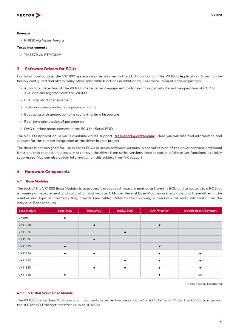
The task of the VX1000 Base Modules is to process the acquired measurement data from the ECU and to route it to a PC that is running a measurement and calibration tool such as CANape. Several Base Modules are available and these differ in the number and type of interfaces they provide (see table). Refer to the following subsections for more information on the individual Base Modules.
Base Module Serial POD HSSL POD HSSL2 POD CAN/FlexRay BroadR-Reach/Ethernet
VX1060 ●
VX1132B ● ●*
VX1132C ●
VX1132H ●
VX1132S ● ●*
VX1135A ● ● ● ●
VX1135C ● ● ●
VX1135D ● ● ● ●
VX1135E ● ● 2x
* = only FlexRay Monitoring
4.1.1 VX1060 Serial Base Module
The VX1060 Serial Base Module is a compact and cost-effective base module for VX154x Serial PODs. The XCP data rate over the 100 Mbit/s Ethernet interface is up to 10 MB/s.

VX1000
7
Figure 3: VX1060 Base Module and VX1543A Serial POD with housing
4.1.1.1 Component Overview
Base Module and accessories
Base Module VX1060 Serial Base Module
Power supply Laboratory cable Plug-in adapter Vehicle plug
Laboratory plug with 3-pin binder connector Vector wall power supply with 3-pin binder connector Vehicle plug with 3-pin binder connector
4.1.1.2 Technical Data
VX1060
Dimensions (LxWxH) 115 x 106 x 32 mm
Weight 330 g
Temperature range –40°C to +70°C
Input voltage 5.5 VDC to 50 VDC
Start-up voltage 7.5 VDC to 50 VDC
Power consumption typ. 250 mA @ 12V (without POD)
Standby consumption 70 mA @ 12V
4.1.2 VX1132 Base Module
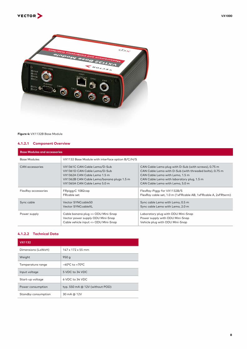
The VX1132 Base Module offers an XCP data rate over the 1000 Mbit/s Ethernet interface of up to 50 MB/s. It is available in four variants with different POD connectors. The variants VX1132B and VX1132S also provide four CAN channels and one FlexRay monitoring channel.
VX1000
8
Figure 4: VX1132B Base Module
4.1.2.1 Component Overview
Base Modules and accessories
Base Modules VX1132 Base Module with interface option B/C/H/S
CAN accessories VX1361C CAN Cable Lemo/D-Sub VX1361D CAN Cable Lemo/D-Sub VX1362A CAN Cable Lemo 1.5 m VX1362B CAN Cable Lemo/banana plugs 1.5 m VX1365A CAN Cable Lemo 5.0 m
CAN Cable Lemo plug with D-Sub (with screws), 0.75 m CAN Cable Lemo with D-Sub (with threaded bolts), 0.75 m CAN Cable Lemo with Lemo, 1.5 m CAN Cable Lemo with laboratory plug, 1.5 m CAN Cable Lemo with Lemo, 5.0 m
FlexRay accessories FRpiggyC 1082cap FRcable set
FlexRay-Piggy for VX1132B/S FlexRay cable set, 1.0 m (1xFRcable AB, 1xFRcable A, 2xFRterm)
Sync cable Vector SYNCcable50 Vector SYNCcableXL
Sync cable Lemo with Lemo, 0.5 m Sync cable Lemo with Lemo, 2.0 m
Power supply
Cable banana plug <> ODU Mini-Snap Vector power supply ODU Mini-Snap Cable vehicle input <> ODU Mini-Snap
Laboratory plug with ODU Mini-Snap Power supply with ODU Mini-Snap Vehicle plug with ODU Mini-Snap
4.1.2.2 Technical Data
VX1132
Dimensions (LxWxH) 147 x 172 x 55 mm
Weight 950 g
Temperature range –40°C to +70°C
Input voltage 5 VDC to 34 VDC
Start-up voltage 6 VDC to 34 VDC
Power consumption typ. 550 mA @ 12V (without POD)
Standby consumption 30 mA @ 12V

VX1000
9
4.1.3 VX1135 Base Module
Compared to the VX1132, the VX1135 Base Module offers a higher XCP data rate of up to 100 MB/s. It is also available in four variants with different POD connectors. All the available variants possess a target BroadR-Reach/Ethernet socket as well as five CAN channels and optionally a fully-featured FlexRay channel. Unlike at the VX1132, the CAN connectors are not designed as Lemo sockets but as D-Sub 9 sockets, as is also the FlexRay channel.
Figure 5: VX1135A Base Module
4.1.3.1 Component Overview
Base modules and accessories
Base Modules VX1135 Base Module with Interface Option A/C/D/E
CAN accessories VX1369E CAN adapter D-Sub9/Lemo(2x) CANcable 2Y
CAN adapter, D-Sub9 with Lemo, 0.1 m Y Cable, D-Sub9 CAN/CAN with 2x D-Sub9 CAN
FlexRay accessories FR/CANcable 2Y Y Cable, D-Sub9 FR/CAN with D-Sub9 FlexRay A&B and D-Sub9 CAN
Sync cable Vector SYNCcable50 Vector SYNCcableXL
Sync cable Lemo with Lemo, 0.5 m Sync cable Lemo with Lemo, 2.0 m
Power supply
Cable banana plug <> ODU Mini-Snap Vector power supply ODU Mini-Snap Cable vehicle input <> ODU Mini-Snap
Laboratory plug with ODU Mini-Snap Vector power supply with ODU Mini-Snap Vehicle plug with ODU Mini-Snap
4.1.3.2 Technical Data
VX1135
Dimensions (LxWxH) 147 x 172 x 55 mm
Weight 1050 g
Temperature range –40°C to +60°C
Input voltage 5 VDC to 34 VDC
Starting voltage 6 VDC to 34 VDC
Power consumption typ. 740 mA @ 12V (without POD)
Standby consumption 1 mA @ 12V

VX1000
10
4.2 PODs
4.2.1 VX154x Serial PODs
Despite their very compact design, the VX154x Serial PODs offer high-performance ECU connections using only a few pins.
Figure 6: VX1543A Serial POD
4.2.1.1 Performance Characteristics
Serial PODs
Target Controller xPC5xxx, V850, XC2000
TriCore Production Device (PD)
TriCore Emulation Device (ED) Data Trace
Measurement data throughput ≤ 1 MB/s ≤ 3 MB/s (TC1xxx) ≤ 5 MB/s (TC2xx, TC3xx)
≤ 5 MB/s (TC1xxED) ≤ 15 MB/s (TC2xx, TC3xx)
Impact on CPU run-time ≈ 4% per 1 MB/s ≈ 4% per 1 MB/s 0%
DAQ RAM requirement ø 3-6 bytes/signal ø 3-6 bytes/signal 0 bytes/3 EMEM tiles
DAQ signals 10,000 10,000 100,000
DAQ events 31 31 256
Minimum measurement interval ≈ 65 µs ≈ 18 µs ≈ 10 µs
Bypassing latency time ≤ 400 µs ≤ 400 µs –
4.2.1.2 Component Overview
PODs and cables
PODs VX1543A Serial POD VX1544A Serial POD VX1544B Serial POD
Target interfaces: DAP, JTAG; 1.2 V up to 5 V IO voltage Target interfaces: JTAG, Zipwire, HSCT; 3.3 V and 5 V IO voltage Target interfaces: DAP2; 3.3 V IO voltage
Cables for VX1543A
VX1349A.xx Serial POD Cables VX1348A Serial POD Cable 2.5 m VX1345A Serial Extension Cable 5.0 m VX1346A Serial Extension Cable 8.0 m VX1341F Serial POD Cable for VX1543 VX1342 Serial Cable 2.0 m VX1345 Serial Cable 5.0 m
Cable tail with connector Cable tail with connector Extension cable Extension cable Integrated device socket Connecting cable Connecting cable
Length: 0.75 m Length: 2.50 m Length: 5.00 m Length: 8.00 m Length: 0.20 m Length: 2.00 m Length: 5.00 m
Cables for VX1544x
VX1349B Serial POD Cable 0.75 m VX1348B Serial POD Cable 2.5 m VX1311B Serial2 Cable 50.A1.B1.A VX1311C Serial2 Cable 80.A1.B1.A VX1341G Serial POD Cable for VX1544 VX1311E Serial2 Cable 50.A1.A1.A VX1311F Serial2 Cable 80.A1.A1.A
Cable tail with connector Cable tail with connector Extension cable Extension cable Integrated device socket Connecting cable Connecting cable
Length: 0.75 m Length: 2.50 m Length: 5.00 m Length: 8.00 m Length: 0.20 m Length: 5.00 m Length: 8.00 m
VX1000
11
4.2.1.3 Technical Data
PODs and cables
VX1543A Serial POD
PCB dimensions (LxWxH) Housing dimensions (LxWxH) PCB weight Temperature range Power supply Power consumption
23 x 24 x 7 mm 53 x 27.5 x 16 mm 3 g –40°C to +115°C from base module typ.< 400 mW
VX1544x Serial POD PCB dimensions (LxWxH) Housing dimensions (LxWxH) PCB weight Temperature range Power supply Power consumption
23 x 24 x 8 mm 53 x 27.5 x 16 mm 3 g –40°C to +115°C from base module typ.< 400 mW
VX134x Serial Cable Temperature range Ingress protection Bending radius (min.)
–40°C to +125°C IP64 (plugged) 6 cm moving, 1.5 cm fixed
VX1311x Serial2 Cable
Temperature range Ingress protection Bending radius (min.)
–40°C to +125°C IP64 (plugged) 7 cm moving, 2 cm fixed
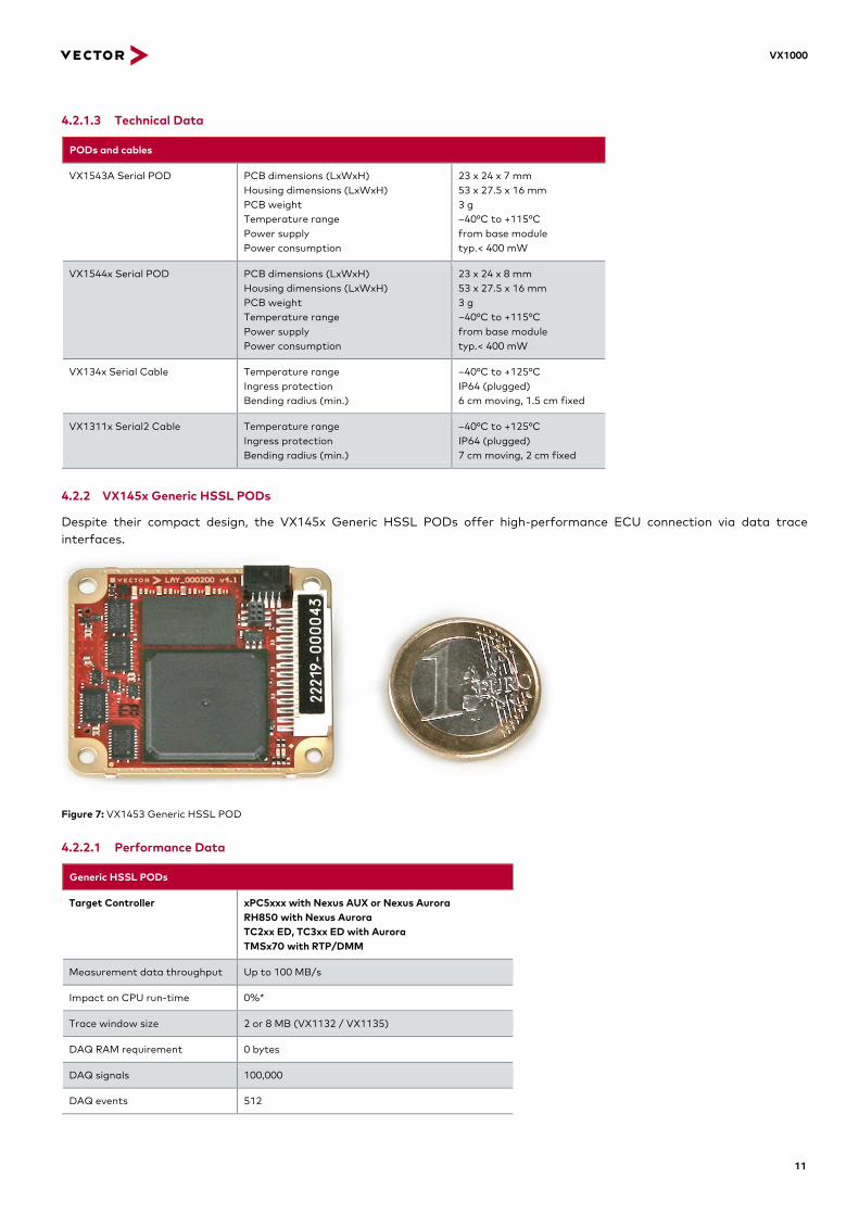
4.2.2 VX145x Generic HSSL PODs
Despite their compact design, the VX145x Generic HSSL PODs offer high-performance ECU connection via data trace interfaces.
Figure 7: VX1453 Generic HSSL POD
4.2.2.1 Performance Data
Generic HSSL PODs
Target Controller xPC5xxx with Nexus AUX or Nexus Aurora RH850 with Nexus Aurora TC2xx ED, TC3xx ED with Aurora TMSx70 with RTP/DMM
Measurement data throughput Up to 100 MB/s
Impact on CPU run-time 0%*
Trace window size 2 or 8 MB (VX1132 / VX1135)
DAQ RAM requirement 0 bytes
DAQ signals 100,000
DAQ events 512

VX1000
12
Minimum measurement interval 8 µs
Bypassing latency time ≈ 300 µs
*Depending on the configuration, data trace may slow down the processor. In such cases, a CPU impact of several percent is possible.
4.2.2.2 Component Overview
PODs and accessories
PODs VX1451 Generic HSSL POD VX1453 Generic HSSL POD
Target interfaces: Nexus AUX, RTP/DMM Target interfaces: Nexus Aurora
HSSL Cables (VX1451/VX1453) VX1379B/C/E.xx HSSL Pigtail VX1379D/F HSSL Panel Socket VX1372 HSSL Cable 2.0 m VX1375 HSSL Cable 5.0 m VX1376A HSSL Cable 5.0 m 3H 45°
Cable tail with socket Integrated device socket Connecting cable Connecting cable Cable, connector at one end, angled
Length: 0.50 m Length: 0.20 m Length: 2.00 m Length: 5.00 m Length: 5.00 m
HSSL2 Cable (only VX1453) VX1381E HSSL2 Pigtail 05.B1.D1.A VX1381B HSSL2 Cable 50.A1.A1.A VX1381C HSSL2 Cable 80.A1.A1.A
HSSL2 Cable tail HSSL2 Cable HSSL2 Cable
Length: 0.50 m Length: 5.00 m Length: 8.00 m
Evalboard Extension Kit for VX1451
Extension Kit for VX1451 VX1321A/B/C Target Flex Adapter VX1322 Samtec-50 Cable
Aluminum housing RTP/DMM/Nexus Target Cable, Mictor Nexus Target Cable, 50-pin, Samtec
Length: 0.25 m Length: 0.25 m
Evalboard Extension Kit for VX1453
Extension Kit for VX1453 VX1902.01x EEK Heads Aurora (NXP) VX1902.02x EEK Head Aurora (IFX)
Aluminum housing with Target Flex Board Variants: 850 MHz, 1.0 GHz, 1.2 GHz, 1.25 GHz; with/without housing Variants: with/without housing
4.2.2.3 Technical Data
PODs and cables
VX1451 Generic HSSL POD PCB dimensions (LxWxH) Housing dimensions (LxWxH) PCB weight Temperature range Power supply Power consumption
40 x 34.5 x 9 mm 92 x 63 x 26.4 mm 10 g –40°C to +105°C from base module typ. ~ 1.5 W
VX1453 Generic HSSL POD PCB dimensions (LxWxH) Housing dimensions (LxWxH) PCB weight Temperature range Power supply Power consumption
40 x 34.5 x 9.2 mm 95 x 46.5 x 25 mm 10 g –40°C to +105°C from base module typ. ~ 1.6 W (RAM deactivated)
VX137x HSSL Cable Temperature range Ingress protection Bending radius (min.)
–40°C to +105°C IP67 (plugged) 7 cm moving, 2 cm fixed
VX1381x HSSL2 Cable Temperature range Ingress protection Bending radius (min)
–40°C to +130°C IP67 (plugged) 7 cm moving, 1.5 cm fixed
4.3 XPOD
4.3.1 VX1621A XPOD
The VX1621A XPOD is a standalone measurement and calibration device that directly supports the standardized XCP protocol without the need of a VX1000 Base Module. The host connection is established via BroadR-Reach/Automotive Ethernet, which requires only a simple conductor pair. A conversion to standard Ethernet is performed using a media converter or BroadR-Reach network adapter such as the VX0312 Ethernet/CAN Interface or via the BroadR-Reach target interface of a VX1135 Base Module.
Thanks to its small dimensions and the available mounting concepts, the VX1621A XPOD is ideal for direct integration into an ECU.

VX1000
13
Figure 8: VX1621A XPOD
4.3.1.1 Performance Data
XPOD
Target Controller TriCore TC2xx Emulation Device (ED)
Measurement data throughput ≤ 5 MB/s
Impact on CPU run-time ≈ 4% per 1 MB/s
DAQ RAM requirement ø 3-6 bytes/signal in EMEM
DAQ signals 10,000
DAQ events 31
Minimum measurement interval ≈ 20 µs
Bypassing latency time –
4.3.1.2 Component Overview
POD and accessories
POD VX1621A XPOD
Accessories VX1325.02A Cable for XPOD VX1710.01A Mounting Frame for XPOD
BroadR-Reach/Power Cable, 0.2 m Mounting Frame for XPOD
4.3.1.3 Technical Data
POD and accessories
VX1621A
PCB dimensions (LxWxH) PCB weight Temperature range Power supply Power consumption, typical / standby
37 x 34.5 x 8.5 mm 10 g –40°C to +120°C from the ECU 1.4 W / < 15 mW
VX1710.01A Dimensions (LxWxH) Weight
39 x 36.5 x 3.5 mm 3 g
VX1000
14
4.4 Network Hardware/Infrastructure Hardware
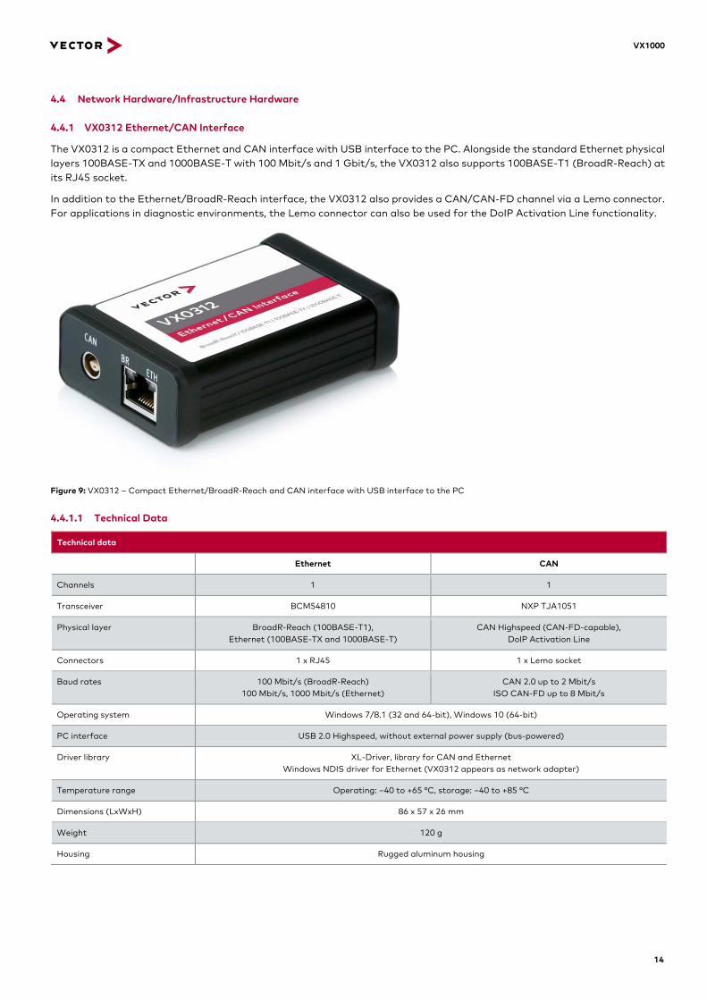
4.4.1 VX0312 Ethernet/CAN Interface
The VX0312 is a compact Ethernet and CAN interface with USB interface to the PC. Alongside the standard Ethernet physical layers 100BASE-TX and 1000BASE-T with 100 Mbit/s and 1 Gbit/s, the VX0312 also supports 100BASE-T1 (BroadR-Reach) at its RJ45 socket.
In addition to the Ethernet/BroadR-Reach interface, the VX0312 also provides a CAN/CAN-FD channel via a Lemo connector. For applications in diagnostic environments, the Lemo connector can also be used for the DoIP Activation Line functionality.
Figure 9: VX0312 – Compact Ethernet/BroadR-Reach and CAN interface with USB interface to the PC
4.4.1.1 Technical Data
Technical data
Ethernet CAN
Channels 1 1
Transceiver BCM54810 NXP TJA1051
Physical layer BroadR-Reach (100BASE-T1), Ethernet (100BASE-TX and 1000BASE-T)
CAN Highspeed (CAN-FD-capable), DoIP Activation Line
Connectors 1 x RJ45 1 x Lemo socket
Baud rates 100 Mbit/s (BroadR-Reach) 100 Mbit/s, 1000 Mbit/s (Ethernet)
CAN 2.0 up to 2 Mbit/s ISO CAN-FD up to 8 Mbit/s
Operating system Windows 7/8.1 (32 and 64-bit), Windows 10 (64-bit)
PC interface USB 2.0 Highspeed, without external power supply (bus-powered)
Driver library XL-Driver, library for CAN and Ethernet Windows NDIS driver for Ethernet (VX0312 appears as network adapter)
Temperature range Operating: –40 to +65 °C, storage: –40 to +85 °C
Dimensions (LxWxH) 86 x 57 x 26 mm
Weight 120 g
Housing Rugged aluminum housing

VX1000
15
5 Configuration and Update Tools
The VXtools are available free-of-charge for configuring and updating the VX1000 hardware. POD and Base Module can be configured either with the standalone VXtools or by the CANape plug-in. The created configurations can be saved on the PC, and it is easy to transfer them to other devices.
5.1 VXconfig
> Convenient configuration of all VX1000 components
> Access to all device parameters
> Processor-specific display of relevant parameters
> Plausibility check of the set parameters
> User guidance in setting the parameters
Figure 10: VXconfig – MPC5xxx-specific settings and plausibility check
5.2 VXupdate
> Easy device updates via update container
> One-button configuration
5.3 CANape Plug-in
> Integration of VXconfig in the CANape interface
> Automatic setting of many VX and XCP parameters
> VX-specific supplemental information in A2L Editor and measurement signal list

Get More Information Visit our website for: > News > Products > Demo software > Support > Training classes > Addresses www.vector.com