Embed Size (px)
Citation preview

Virtual Voltage Termination(VVT Technology)
A White Paper
inventuspower.com
An Introduction to Lithium-ion Battery Charging Algorithm
inventuspower.com 2
Virtual Voltage Termination
Table of ContentsIntroduction . . . . . . . . . . . . . . . . . . . . . . . . . . . . . . . . . . . . . . . 3
CC/CV Versus VVT Charging . . . . . . . . . . . . . . . . . . . . . . . . 3
The Effect of Impedance on Battery Charging . . . . . . . . .4
. . . . . . . . . . . . . . . . . . . . 6
. . . . . . . . . . . . . . . . . . . . 8
. 9
. 10
13
VVT and Cell Voltage Monitoring .
Charge Time, Power and Benefits
Conclusion . . . . . . . . . . . . . . . . . . . . . . . . . . . . . . . . . . . . . . .
Appendix A . . . . . . . . . . . . . . . . . . . . . . . . . . . . . . . . . . . . .
Appendix B . . . . . . . . . . . . . . . . . . . . . . . . . . . . . . . . . . . . . .
About Inventus Power . . . . . . . . . . . . . . . . . . . . . . . . . . . . 14
inventuspower.com 3
Virtual Voltage Termination
Introduction
The standard method for charging Lithium-ion (Li-ion) batteries is the constant current/constant voltage (CC/CV) method. It incorporates a two-step process of constant current (CC) followed by a constant voltage (CV) charge phase. In the first stage of the charging process, a constant current equal to or lower than the maximum charge rate for a particular cell is applied. This stage continues until the battery pack voltage approaches the preset threshold at the charger contacts. Once the charging voltage approaches the preset level, current begins to taper exponentially until a cutoff threshold is achieved.
Although CC/CV is widely used across the battery industry, it does have limitations. The charging voltage is fixed and typical chargers cannot compensate for changes of a resistive string within the battery pack. If faster charging is needed, for example, the constant charging current would need to be increased, inducing even greater internal losses.
Realizing the limitations of standard CC/CV chargers, Inventus Power™ has developed a patented method that compensates for internal battery resistance by creating two active modes, where the transition from the CC to the CV stage is controlled by a microprocessor allowing active control by monitoring actual cell voltage during the charging process.
This functionality is achieved without a requirement for additional feedback signals. This subsequently creates greater allowances for the input charging voltage.
Virtual Voltage Termination (VVT) Technology: An Introduction to Lithium-ion Battery Charging Algorithm explores the technology behind VVT and the opportunities it creates for faster charging or charging with less power consumption for a given application.
CC/CV Versus VVT Charging
A CC/CV charger uses its charger contacts as the charge voltage reference point. As shown in Figure 1, this reference point can be significantly different than the cell-stack voltage reference point inside the battery. This difference in voltage reference points can impact the charge performance of a battery.
The charger itself is essentially a voltage limited, current controlled source. When the maximum battery input voltage threshold is reached during the CC stage, the charger transitions into a voltage regulated, steady state CV stage. The current tapers off as the cells continue accepting charge. Once the current tapers to a predetermined level, usually a value of C/10 to C/20 of nominal battery pack capacity (C), the charge process is terminated.
The transition from CC to CV is passive or analog. The standard Li-ion battery charger receives no feedback on the relative state of charge of the cells as the battery management and protection circuitry present impedance between the charge terminals and the cells themselves.
The Inventus Power VVT charging algorithm eliminates the effect of resistive losses in the battery pack and charges the cell stack inside the battery pack.
inventuspower.com 4
Virtual Voltage Termination
At the CC/CV transition point, the relative state of charge is approximately 75% in this example. As the time axis indicates,charge time to obtain the remaining 25% of relative capacity requires a much longer period during the CV mode.
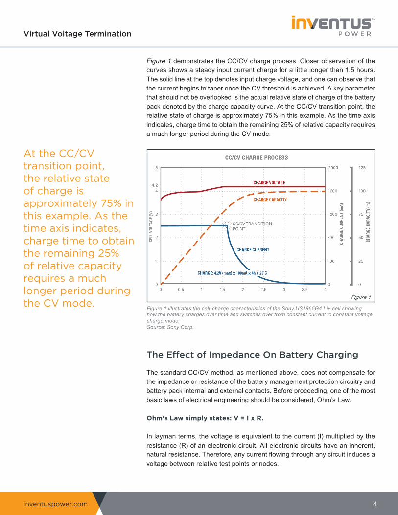
Figure 1 demonstrates the CC/CV charge process. Closer observation of the curves shows a steady input current charge for a little longer than 1.5 hours. The solid line at the top denotes input charge voltage, and one can observe that the current begins to taper once the CV threshold is achieved. A key parameter that should not be overlooked is the actual relative state of charge of the battery pack denoted by the charge capacity curve. At the CC/CV transition point, the relative state of charge is approximately 75% in this example. As the time axis indicates, charge time to obtain the remaining 25% of relative capacity requires a much longer period during the CV mode.
The Effect of Impedance On Battery Charging
The standard CC/CV method, as mentioned above, does not compensate for the impedance or resistance of the battery management protection circuitry and battery pack internal and external contacts. Before proceeding, one of the most basic laws of electrical engineering should be considered, Ohm’s Law.
Ohm’s Law simply states: V = I x R.
In layman terms, the voltage is equivalent to the current (I) multiplied by the resistance (R) of an electronic circuit. All electronic circuits have an inherent, natural resistance. Therefore, any current flowing through any circuit induces a voltage between relative test points or nodes.
Figure 1 illustrates the cell-charge characteristics of the Sony US1865G4 Li+ cell showing how the battery charges over time and switches over from constant current to constant voltage charge mode.Source: Sony Corp.
Figure 1
inventuspower.com 5
Virtual Voltage Termination
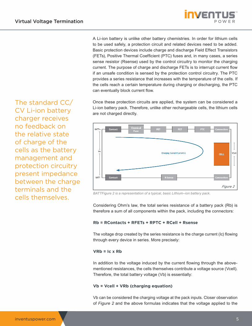
A Li-ion battery is unlike other battery chemistries. In order for lithium cells to be used safely, a protection circuit and related devices need to be added. Basic protection devices include charge and discharge Field Effect Transistors (FETs), Positive Thermal Coefficient (PTC) fuses and, in many cases, a series sense resistor (Rsense) used by the control circuitry to monitor the charging current. The purpose of charge and discharge FETs is to interrupt current flow if an unsafe condition is sensed by the protection control circuitry. The PTC provides a series resistance that increases with the temperature of the cells. If the cells reach a certain temperature during charging or discharging, the PTC can eventually block current flow.
Once these protection circuits are applied, the system can be considered a Li-ion battery pack. Therefore, unlike other rechargeable cells, the lithium cells are not charged directly.
The standard CC/CV Li-ion battery charger receives no feedback on the relative state of charge of the cells as the battery management and protection circuitry present impedance between the charge terminals and the cells themselves.
BATTFigure 2 is a representation of a typical, basic Lithium–ion battery pack.
Figure 2
Considering Ohm’s law, the total series resistance of a battery pack (Rb) is therefore a sum of all components within the pack, including the connectors:
Rb = RContacts + RFETs + RPTC + RCell + Rsense
The voltage drop created by the series resistance is the charge current (Ic) flowingthrough every device in series. More precisely:
VRb = Ic x Rb
In addition to the voltage induced by the current flowing through the above-mentioned resistances, the cells themselves contribute a voltage source (Vcell).Therefore, the total battery voltage (Vb) is essentially:
Vb = Vcell + VRb (charging equation)
Vb can be considered the charging voltage at the pack inputs. Closer observation of Figure 2 and the above formulas indicates that the voltage applied to the
inventuspower.com 6
Virtual Voltage Termination
cells being charged is lower than the input charging voltage since the battery resistance induces a voltage drop as well. As the current tapers during the CV stage, the cells slowly approach the input charging voltage potential.
In addition, as the battery charges, the cell and the PTC heat increase. This not only makes the voltage drop induced by the battery greater, but increases the overall losses. Due to limited power provided by the standard CC/CV charger, the charge time subsequently increases.
Another potential issue with CC/CV charging is the effect of unusually high resistance. If, for any reason (aging contacts, for example), the battery resistance becomes very high, the charger may not be able to charge the battery pack within the allocated time period. If full charging is needed, the charge time may become very long. Furthermore, the resistance stack up may induce charging oscillation and incomplete charging. An example of charging oscillation is provided in Appendix A.
VVT and Cell Voltage Monitoring
Although CC/CV is a solid method, widely used across the battery industry, it does have limitations. The charging voltage is fixed, and the charger cannot compensate for dynamic changes of a resistive string within the battery pack. If faster charging is needed, for example, the constant charging current would need to be increased, inducing even greater internal losses.
Realizing the limitations of standard CC/CV chargers, Inventus Power developed a method that compensates for internal battery resistance. This is achieved by creating two active modes, where the transition from the CC to the CV stage is controlled by the microprocessor. This active transition method was patented as VVT, or Virtual Voltage Termination technology.
The key for achieving active control is the ability to monitor actual cell voltage during the charging process without a requirement for additional feedback signals. This subsequently allows greater headroom for the input charging voltage. Active cell voltage measurement is obtained by momentary charge interruption, eliminating the effect of impedance. In order to explain the process more precisely, referencing Ohm’s Law is once again necessary:
By interrupting the charge current momentarily, the Ic effectively becomes 0. Therefore, considering the charging equation mentioned above:
Vb = Vcell + VRb
Vb = Vcell + Ic x Rb
Vb = Vcell + 0 x Rb
Vb = Vcell
The key for achievingactive control is the ability to monitor actual cell voltage during the charging process without a requirement for additional feedback signals.
inventuspower.com 7
Virtual Voltage Termination
As the derivation above describes, momentary interruption of the charge current allows the voltage at the battery inputs (Vb) to be equivalent to the voltage of the cells by eliminating the effect of battery resistance (Rb).
The key advantage of VVT is the active transition from the CC to the CV stage. Where the standard CC/CV charger can be considered analog, a VVT charger uses a microprocessor to monitor cell voltage levels and determine the point of transition. This active control of the charging process enables a longer duration of the CC stage and a more precise transition to CV.
Virtual measurement of the cell voltage allows the charger to optimize the input voltage threshold and extend the CC stage. Due to the impedance effect of the protection circuitry, the cell voltage never exceeds the optimal levels defined by the manufacturer. The CC process continues until the cell voltage approaches a predetermined level.
Once the cell voltage reaches the transition voltage level, the microprocessor reconfigures the regulation mode and transitions into the CV stage. The battery input charging voltage is reduced accordingly, and the charging current begins to taper in a similar manner to standard CC/CV charging.
Once the charge current tapers to a predetermined threshold, the charging process stops.The termination criterion is therefore equivalent to the standard CC/CV process.
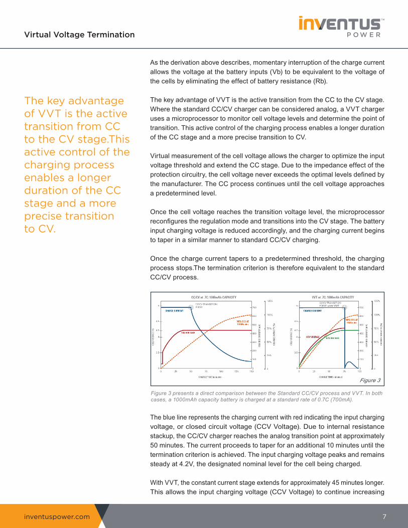
The blue line represents the charging current with red indicating the input charging voltage, or closed circuit voltage (CCV Voltage). Due to internal resistance stackup, the CC/CV charger reaches the analog transition point at approximately 50 minutes. The current proceeds to taper for an additional 10 minutes until the termination criterion is achieved. The input charging voltage peaks and remains steady at 4.2V, the designated nominal level for the cell being charged.
With VVT, the constant current stage extends for approximately 45 minutes longer. This allows the input charging voltage (CCV Voltage) to continue increasing
The key advantage of VVT is the active transition from CC to the CV stage.This active control of the charging process enables a longer duration of the CC stage and a more precise transitionto CV.
Figure 3 presents a direct comparison between the Standard CC/CV process and VVT. In both cases, a 1000mAh capacity battery is charged at a standard rate of 0.7C (700mA).
Figure 3
inventuspower.com 8
Virtual Voltage Termination
and compensate for the internal resistances. The key parameter to note in the VVT example is the green Virtual Voltage Termination 8 open circuit voltage or the OCV line. It denotes the actual cell voltage level measured by the charge interruption process. The cell voltage therefore never extends beyond the 4.2Vnominal threshold, as can be viewed by comparing the green OCV line of the VVT graph with the red CCV Voltage line of the CC/CV graph.
Once the transition to the CV stage occurs, the current taper process is significantly shorter. The overall charge is terminated in less than 100 minutes versus the 150 minutes with the CC/CV process. This is a clear indication of a more time efficient charging process.
Charge Time, Power and Benefits
The example in Figure 3 presents a case in which the VVT charging process was completed approximately 33% faster than with a comparable CC/CV charger, utilizing equivalent charging current.
Another benefit of VVT charging is that the microprocessor-based circuit allows for independent control of charge time and power. The charger can easily be configured to optimize either the charge time or the input power without requiring hardware modifications.
If charging time is not important, the VVT charging process can be modified to reduce the charging current level while still maintaining a comparable overall charge time to a CC/CV charger. Besides providing a more efficient charge, VVT allows for a less substantial input regulator and reduced overall charge power, as well as lowering the cost of a charging system. In other words, charge time comparable with CC/CV chargers can be achieved with lower input current and power.
By combining VVT with other microprocessor based technologies, OEMs can improve charging, fuel gauge accuracy and data transfer integration without the added costs and size of additional hardware. This method reduces components, complexity, and overall unit cost and provides built in design flexibility for next gen products.
VVT allows the charge time to stay consistent over the life of the battery pack regardless of degrading conditions or other component aging effects that can increase circuit impedance. This improves overall reliability and durability of a rechargeable device.
With VVT, the constant current stage extends for most of the chargingperiod, until the microprocessor senses nominal cell voltage and initiates the transition event.
inventuspower.com 9
Virtual Voltage Termination
Conclusion
VVT is essentially an improved CC/CV process. By eliminating the effect of resistive loses in the battery pack, the VVT charging algorithm charges the battery cell stack rather than the outside battery terminals. The charging algorithm therefore does not deviate from the industry-accepted method for Li-ion battery packs.
With VVT, the constant current stage extends for most of the charging period, until the microprocessor senses nominal cell voltage and initiates the transition event. The frequency of cell voltage sensing is adjusted in order to ensure a safe transition.
Once the transition to Constant Voltage mode occurs, the charge current proceeds to taper in a similar manner to standard CC/CV charging, only this taper period is much shorter in duration.
Charge termination is based on the same threshold as with industry standard chargers and could be adjusted easily based on vendor guidance and customer needs.
The major difference between CC/CV and VVT is only in the manner in which the transition threshold is determined. With CC/CV, the process is analog and cannot compensate for series resistance. This requires a long CV stage and yields less efficient charging. In addition, resistance changes as a result of reduced charge power during the CV stage can potentially induce charging instability.
With VVT, the transition is determined digitally. Once the cells reach the predetermined transition voltage, the charger reverts to the CV stage and it remains in this mode without a potential to revert back to the CC stage. VVT therefore capitalizes on the CC stage and yields a more efficient, faster charge cycle.
In summary, VVT is essentially an improved industry standard CC/CV process. It incorporates a microprocessor to actively transition between the CC and CV stages. Overall charge efficiency is therefore greatly improved while preserving a safe and effective charging process.
The major differencebetween CC/CV and VVT is only in the manner in which the transition threshold is determined. With CC/CV, the process is analog, with VVT, the transition is determined digitally
Inventus Power has received four patents for its VVT charging algorithm.
inventuspower.com 10
Virtual Voltage Termination
Appendix A: An Example of CC/CV Oscillation
The ChallengeOne of the rare side effects of CC/CV is the potential for oscillations due to the resistance effect and the battery not reaching full charge.
In this example, the customer was trying to charge a Li-ion battery in a system with high total resistance/impedance. The charger consisted of a cradle, which contained a CC/CV charger. The sub-system containing the rechargeable battery pack was placed in the cradle and would automatically start charging based on the battery voltage. The problem was that near the end of charge, the LED charge indication would start to oscillate, meaning that the charger was turning on and off repeatedly. Further, the customers observed that the battery was not meeting the expected run time.
The StudyOur investigation showed that the batteries were not receiving a full charge. At best, a battery would receive approximately 85% of its full charge. Further investigation showed the root cause was the excessive impedances in the charging system.
Our first step to solving this problem was to analyze the contributors to system impedance. The first lines of resistance, in this case, were the charging contacts in the cradle, which interfaced to the charging contacts on the sub-system. In addition to charging contacts, the system had internal coil spring connectors, which interfaced with the battery terminals. Furthermore, protection circuitry within the battery pack, consisting of protection transistors, thermal resistors and the cells themselves, added additional impedance. Some of these elements, such as the coil spring contacts, aged and the subsequent resistance increased. This created an ever-increasing voltage drop between the battery pack chargingnodes and the actual cells.
Please refer to Figure 1 for the following explanations and analysis:
inventuspower.com 11
Virtual Voltage Termination
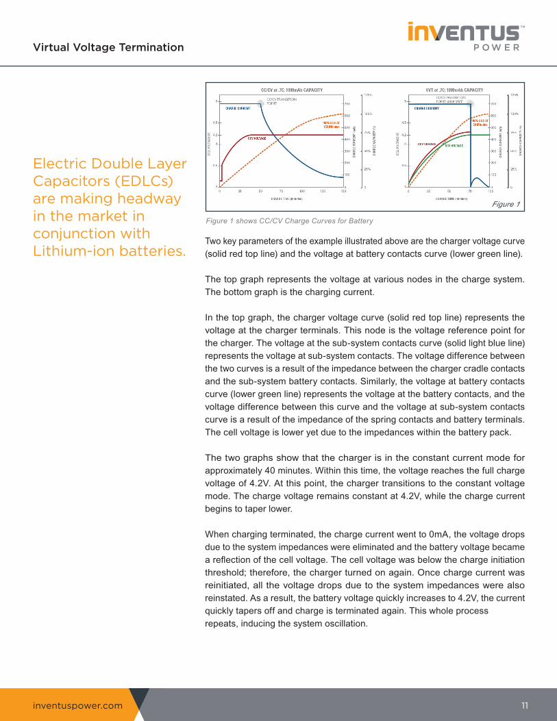
Two key parameters of the example illustrated above are the charger voltage curve (solid red top line) and the voltage at battery contacts curve (lower green line).
The top graph represents the voltage at various nodes in the charge system. The bottom graph is the charging current.
In the top graph, the charger voltage curve (solid red top line) represents the voltage at the charger terminals. This node is the voltage reference point for the charger. The voltage at the sub-system contacts curve (solid light blue line) represents the voltage at sub-system contacts. The voltage difference between the two curves is a result of the impedance between the charger cradle contacts and the sub-system battery contacts. Similarly, the voltage at battery contacts curve (lower green line) represents the voltage at the battery contacts, and the voltage difference between this curve and the voltage at sub-system contacts curve is a result of the impedance of the spring contacts and battery terminals. The cell voltage is lower yet due to the impedances within the battery pack.
The two graphs show that the charger is in the constant current mode for approximately 40 minutes. Within this time, the voltage reaches the full charge voltage of 4.2V. At this point, the charger transitions to the constant voltage mode. The charge voltage remains constant at 4.2V, while the charge current begins to taper lower.
When charging terminated, the charge current went to 0mA, the voltage drops due to the system impedances were eliminated and the battery voltage became a reflection of the cell voltage. The cell voltage was below the charge initiation threshold; therefore, the charger turned on again. Once charge current was reinitiated, all the voltage drops due to the system impedances were also reinstated. As a result, the battery voltage quickly increases to 4.2V, the current quickly tapers off and charge is terminated again. This whole processrepeats, inducing the system oscillation.
Electric Double Layer Capacitors (EDLCs) are making headway in the market in conjunction with Lithium-ion batteries.
Figure 1 shows CC/CV Charge Curves for Battery
Figure 1
inventuspower.com 12
Virtual Voltage Termination
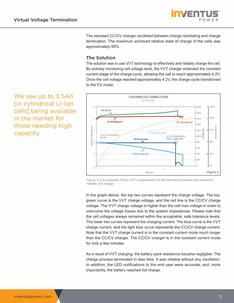
The standard CC/CV charger oscillated between charge reinitiating and charge termination. The maximum achieved relative state of charge of the cells was approximately 85%.
The SolutionThe solution was to use VVT technology to effectively and reliably charge the cell.By actively monitoring cell voltage level, the VVT charger extended the constant current stage of the charge cycle, allowing the cell to reach approximately 4.2V. Once the cell voltage reached approximately 4.2V, the charge cycle transitioned to the CV mode.
In the graph above, the top two curves represent the charge voltage. The top, green curve is the VVT charge voltage, and the red line is the CC/CV charge voltage. The VVT charge voltage is higher than the cell max voltage in order to overcome the voltage losses due to the system impedances. Please note that the cell voltages always remained within the acceptable, safe tolerance levels. The lower two curves represent the charging current. The blue curve is the VVT charge current, and the light blue curve represents the CC/CV charge current. Note that the VVT charge current is in the constant current mode much longer than the CC/CV charger. The CC/CV charger is in the constant current mode for only a few minutes.
As a result of VVT charging, the battery pack resistance became negligible. The charge process terminated in less time. It was reliable without any oscillation. In addition, the LED notifications to the end user were accurate, and, more importantly, the battery reached full charge.
We see up to 3.5Ah[in cylindrical Li-Ioncells] being availablein the market for those needing high capacity.
Figure 2 is an example of how VVT compensated for the internal resistance and enabled a reliable, full charge.
Figure 2
inventuspower.com 13
Virtual Voltage Termination
Appendix B: An Example of Charging with Less Power
The ChallengeIn this example, the customer had a requirement for a 4-bay Li-ion battery CC/CV charger with the following stipulations:
• Power Supply: Maximum allowed 100W power supply• Charge Duration: Allowed to charge in 4 hours max• Charge Current Per Battery: Allowed 1.1A / bay max
The customer indicated that the batteries did not need to be rapid charged, and that the 4-hour maximum charge time was acceptable. By implementing VVT charging technology, tests showed that the batteries could be fully charged within 4 hours with approximately 750mA maximum charge current.
The SolutionThe final design was a 4-bay Li-ion battery charger with VVT charge technology. One microcontroller independently controlled each charging bay, which eliminated the need for 4 integrated charging circuits. The maximum charge current was 750mA, enabling the batteries to charge within 4 hours. The input power supply could be reduced from a standard 100W power supply to a more cost-effective standard 72W power supply.
This was possible because the VVT charger could extend the CC stage and actively monitor the cell voltages, requiring less charging power. Thus, the system input power could be reduced by 40%.
The net result of the reduced input power adapter was a significant cost savings to the customer. Not only did VVT reduce project cost, but it also provided a less stressful charge for the cells and lower subsequent thermal side effects.

inventuspower.com 14
Virtual Voltage Termination
About Inventus Power
Inventus Power, founded in 1960, is the leading provider of advanced battery systems for global OEMs. We specialize in the design and manufacture of battery packs, chargers, and power supplies across a broad range of portable, motive & stationary applications.
With multi-country locations across four continents and manufacturing facilities in the U.S., Mexico, Brazil, China, & Malaysia, we are strategically positioned to support the needs of global brands.
From design & engineering to performance testing & mass production, Inventus Power provides accelerated end-to-end solutions. Our broad market/application expertise, technology agnostic approach, global footprint, and vertical integration allow us to deliver safe, reliable & innovative power solutions at an exceptional speed to market.
For more information, visit inventuspower.com.
IP_WP_VVT_041719_01


![Haemopathologia - users.atw.huusers.atw.hu/aokszote/download.php?fname=./02] PREKLINIKAI MODUL... · Normocytás • Microcytás - kis vvt-k • Macrocytás - nagyobb vvt-k Anaemiák](https://img.pdfslide.us/doc/110x75/5e1909169a6787782760e212/haemopathologia-usersatw-preklinikai-modul-normocyts-a-microcyts.jpg)