Embed Size (px)
Citation preview
Westinghouse
VVER-1000 Fuel Products
BackgroundThe Robust Westinghouse Fuel Assembly (RWFA) design has rapidly become the Westinghouse standard fuel product for the VVER-1000 units in Ukraine. The RWFA design is an evolution of Westinghouse´s previous VVER-1000 fuel design, WFA, which was first introduced as Lead Test Assemblies in South Ukraine Unit 3 in 2005.
Mechanical features and stronger materials were introduced in RWFA to avoid damage from mechanical interference during the core loading and unloading. The RWFA product has demonstrated excellent performance and reliability. Moreover, it is designed for the conditions following planned power uprates as well as load follow operation.
Westinghouse is also introducing a modified RFWA design for the Temelín nuclear power plant in the Czech Republic. The new design, which will be demonstrated in a Lead Test Assembly (LTA) program, will include fewer spacer grids for the assembly to be compatible with non-Westinghouse fuel, and material upgrades to further benefit the fuel economy and performance.
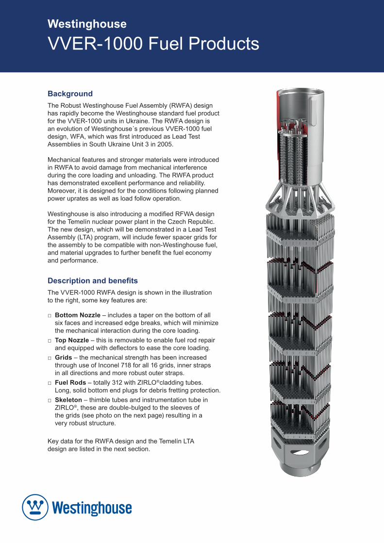
Description and benefitsThe VVER-1000 RWFA design is shown in the illustration to the right, some key features are:
□ Bottom Nozzle – includes a taper on the bottom of all six faces and increased edge breaks, which will minimize the mechanical interaction during the core loading.
□ Top Nozzle – this is removable to enable fuel rod repair and equipped with deflectors to ease the core loading.
□ Grids – the mechanical strength has been increased through use of Inconel 718 for all 16 grids, inner straps in all directions and more robust outer straps.
□ Fuel Rods – totally 312 with ZIRLO®cladding tubes. Long, solid bottom end plugs for debris fretting protection.
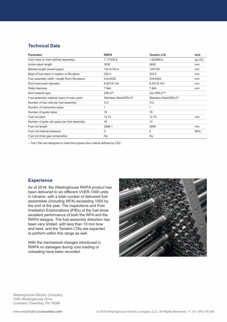
□ Skeleton – thimble tubes and instrumentation tube in ZIRLO®, these are double-bulged to the sleeves of the grids (see photo on the next page) resulting in a very robust structure.
Key data for the RWFA design and the Temelín LTA design are listed in the next section.
Westinghouse Electric Company1000 Westinghouse DriveCranberry Township, PA 16066
www.westinghousenuclear.com © 2018 Westinghouse Electric Company LLC. All Rights Reserved. 11.18 / SFE-18-026
Experience As of 2018, the Westinghouse RWFA product has been delivered to six different VVER-1000 units in Ukraine, with a total number of delivered fuel assemblies (including WFA) exceeding 1000 by the end of the year. The inspections and Post Irradiation Examinations (PIEs) of the fuel show excellent performance of both the WFA and the RWFA designs. The fuel assembly distortion has been very limited, with less than 10 mm bow and twist, and the Temelín LTAs are expected to perform within this range as well.
With the mechanical changes introduced in RWFA no damages during core loading or unloading have been recorded.
Technical Data
Parameter RWFA Temelín LTA UnitFuel mass (in fuel rod/fuel assembly) 1.77/550.8 1.83/569.6 kg UO2
Active stack length 3530 3650 mmBlanket length (lower/upper) 152.4/152.4 120/150 mmBase of fuel stack in relation to Rb-plane 228.4 203.5 mmFuel assembly width / length (from Rb-plane) 234/4520 234/4520 mmRod inner/outer diameter 8.001/9.144 8.001/9.144 mmPellet diameter 7.844 7.844 mmRod material type ZIRLO® Opt ZIRLO™ Fuel assembly material types of main parts Stainless Steel/ZIRLO® Stainless Steel/ZIRLO® Number of fuel rods per fuel assembly 312 312Number of instrument tubes 1 1Number of guide tubes 18 18Fuel rod pitch 12.75 12.75 mmNumber of grids (all types) per fuel assembly 16 13Fuel rod length 3898.1 3908 mmFuel rod internal pressure 2 2 MPaFuel rod inner gas composition He He
– The LTAs are designed to meet the bypass flow criteria defined by CEZ.
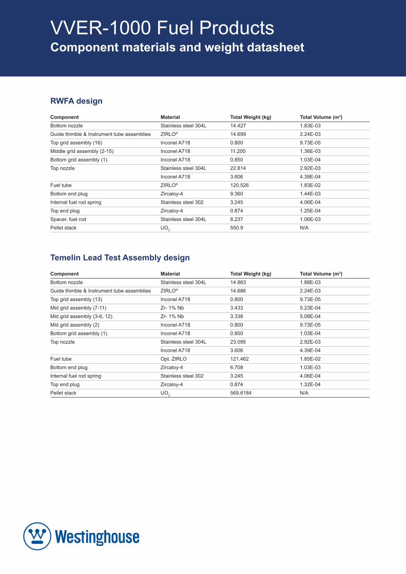
RWFA design
Component Material Total Weight (kg) Total Volume (m3)Bottom nozzle Stainless steel 304L 14.427 1.83E-03Guide thimble & Instrument tube assemblies ZIRLO® 14.699 2.24E-03Top grid assembly (16) Inconel A718 0.800 9.73E-05Middle grid assembly (2-15) Inconel A718 11.200 1.36E-03Bottom grid assembly (1) Inconel A718 0.850 1.03E-04Top nozzle Stainless steel 304L 22.814 2.92E-03
Inconel A718 3.606 4.39E-04Fuel tube ZIRLO® 120.526 1.83E-02Bottom end plug Zircaloy-4 9.360 1.44E-03Internal fuel rod spring Stainless steel 302 3.245 4.06E-04Top end plug Zircaloy-4 0.874 1.25E-04Spacer, fuel rod Stainless steel 304L 8.237 1.06E-03Pellet stack UO2 550.9 N/A
Temelín Lead Test Assembly design
Component Material Total Weight (kg) Total Volume (m3)Bottom nozzle Stainless steel 304L 14.863 1.88E-03Guide thimble & Instrument tube assemblies ZIRLO® 14.686 2.24E-03Top grid assembly (13) Inconel A718 0.800 9.73E-05Mid grid assembly (7-11) Zr- 1% Nb 3.433 5.23E-04Mid grid assembly (3-6, 12) Zr- 1% Nb 3.338 5.08E-04Mid grid assembly (2) Inconel A718 0.800 9.73E-05Bottom grid assembly (1) Inconel A718 0.850 1.03E-04Top nozzle Stainless steel 304L 23.095 2.92E-03
Inconel A718 3.606 4.39E-04Fuel tube Opt. ZIRLO 121.462 1.85E-02Bottom end plug Zircaloy-4 6.708 1.03E-03Internal fuel rod spring Stainless steel 302 3.245 4.06E-04Top end plug Zircaloy-4 0.874 1.32E-04Pellet stack UO2 569.6184 N/A
VVER-1000 Fuel Products Component materials and weight datasheet
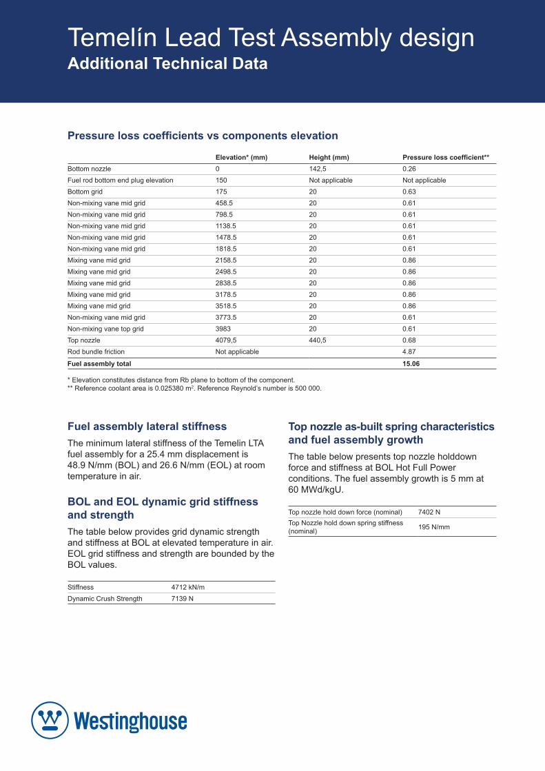
Pressure loss coefficients vs components elevation
Elevation* (mm) Height (mm) Pressure loss coefficient**Bottom nozzle 0 142,5 0.26Fuel rod bottom end plug elevation 150 Not applicable Not applicableBottom grid 175 20 0.63Non-mixing vane mid grid 458.5 20 0.61Non-mixing vane mid grid 798.5 20 0.61Non-mixing vane mid grid 1138.5 20 0.61Non-mixing vane mid grid 1478.5 20 0.61Non-mixing vane mid grid 1818.5 20 0.61Mixing vane mid grid 2158.5 20 0.86Mixing vane mid grid 2498.5 20 0.86Mixing vane mid grid 2838.5 20 0.86Mixing vane mid grid 3178.5 20 0.86Mixing vane mid grid 3518.5 20 0.86Non-mixing vane mid grid 3773.5 20 0.61Non-mixing vane top grid 3983 20 0.61Top nozzle 4079,5 440,5 0.68Rod bundle friction Not applicable 4.87
Fuel assembly total 15.06
* Elevation constitutes distance from Rb plane to bottom of the component.** Reference coolant area is 0.025380 m2. Reference Reynold’s number is 500 000.
Temelín Lead Test Assembly design Additional Technical Data
Fuel assembly lateral stiffnessThe minimum lateral stiffness of the Temelin LTA fuel assembly for a 25.4 mm displacement is 48.9 N/mm (BOL) and 26.6 N/mm (EOL) at room temperature in air.
BOL and EOL dynamic grid stiffness and strengthThe table below provides grid dynamic strength and stiffness at BOL at elevated temperature in air. EOL grid stiffness and strength are bounded by the BOL values.
Stiffness 4712 kN/mDynamic Crush Strength 7139 N
Top nozzle as-built spring charac teristics and fuel assembly growthThe table below presents top nozzle holddown force and stiffness at BOL Hot Full Power conditions. The fuel assembly growth is 5 mm at 60 MWd/kgU.
Top nozzle hold down force (nominal) 7402 NTop Nozzle hold down spring stiffness (nominal) 195 N/mm