Embed Size (px)
Citation preview
DYNAMICS OF MACHINES 10ME54
Dept of Mechanical Engineering, SJBIT Page 1
VTU QUESTION BANK SOLUTION
UNIT - 1
Static Force Analysis
1. Define equilibrium with respect to two force members and three force members.
(04 Marks)(June 2015)
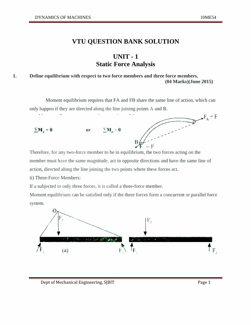
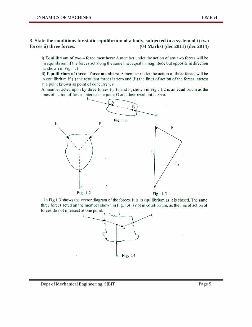
Moment equilibrium requires that FA and FB share the same line of action, which can
only happen if they are directed along the line joining points A and B.
Therefore, for any two-force member to be in equilibrium, the two forces acting on the
member must have the same magnitude, act in opposite directions and have the same line of
action, directed along the line joining the two points where these forces act.
ii) Three-Force Members:
If a subjected to only three forces, it is called a three-force member.
Moment equilibrium can be satisfied only if the three forces form a concurrent or parallel force
system.
DYNAMICS OF MACHINES 10ME54
Dept of Mechanical Engineering, SJBIT Page 2
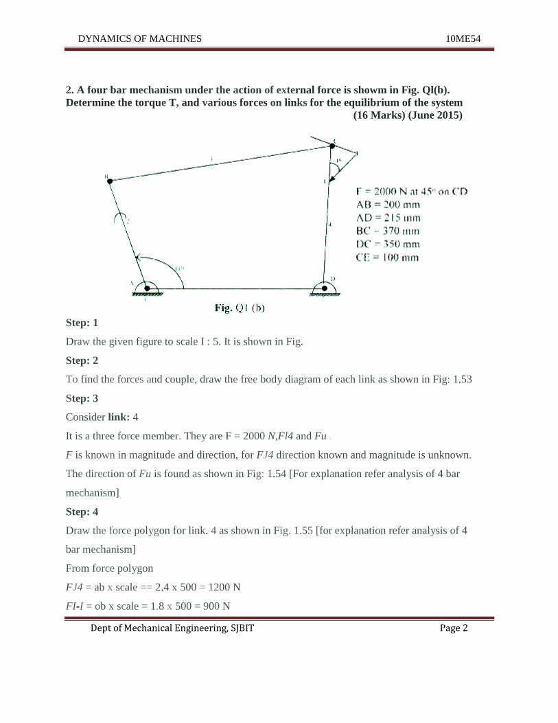
2. A four bar mechanism under the action of external force is showm in Fig. Ql(b).
Determine the torque T, and various forces on links for the equilibrium of the system
(16 Marks) (June 2015)
Step: 1
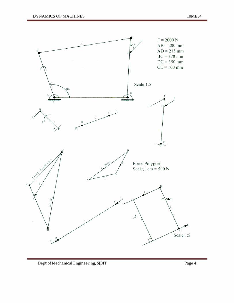
Draw the given figure to scale I : 5. It is shown in Fig.
Step: 2
To find the forces and couple, draw the free body diagram of each link as shown in Fig: 1.53
Step: 3
Consider link: 4
It is a three force member. They are F = 2000 N,Fl4 and Fu .
F is known in magnitude and direction, for FJ4 direction known and magnitude is unknown.
The direction of Fu is found as shown in Fig: 1.54 [For explanation refer analysis of 4 bar
mechanism]
Step: 4
Draw the force polygon for link. 4 as shown in Fig. 1.55 [for explanation refer analysis of 4
bar mechanism]
From force polygon
FJ4 = ab x scale == 2.4 x 500 = 1200 N
FI-I = ob x scale = 1.8 x 500 = 900 N
DYNAMICS OF MACHINES 10ME54
Dept of Mechanical Engineering, SJBIT Page 3
Step: 5
Consider link: 3
It is a two force member i.e., F43 and F23 For equilibrium these two forces are equal and
opposite and acts along axis of BC. But since F43and F34arte equal and opposite. F34 = F43=
F23 = 1200 N
Step: 6
Consider link: 2
It is a two force member i.e., F32and F,~ and a torque T2 .
F3~and F23 are equal and opposite Also for equilibrium F)2 and FI2 are equal and opposite as
shown in Fig Fl.I=F32=FI2= 1200N
Now. Torque, T1 = FJ2 h, where h = 3.96 x5 = 19.8 em = 198 mm
= 1200 x 198
= 237600 N mm
= 237.6 Nm(cw)
DYNAMICS OF MACHINES 10ME54
Dept of Mechanical Engineering, SJBIT Page 4
DYNAMICS OF MACHINES 10ME54
Dept of Mechanical Engineering, SJBIT Page 5
3. State the conditions for static equilibrium of a body, subjected to a system of i) two
forces ii) three forces. (04 Marks) (dec 2011) (dec 2014)
DYNAMICS OF MACHINES 10ME54
Dept of Mechanical Engineering, SJBIT Page 6
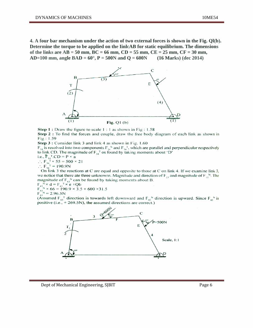
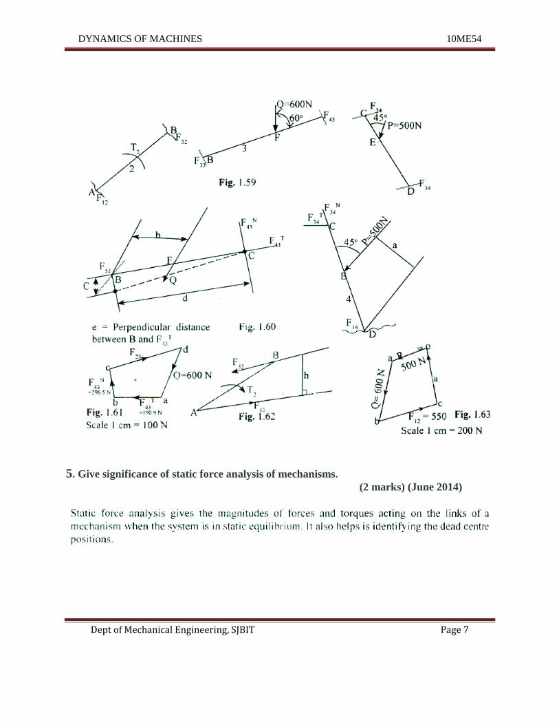
4. A four bar mechanism under the action of two external forces is shown in the Fig. Ql(b).
Determine the torque to be applied on the IinlcAB for static equilibrium. The dimensions
of the links are AB = 50 mm, BC = 66 mm, CD = 55 mm, CE = 25 mm, CF = 30 mm,
AD=100 mm, angle BAD = 60°, P = 500N and Q = 600N (16 Marks) (dec 2014)
DYNAMICS OF MACHINES 10ME54
Dept of Mechanical Engineering, SJBIT Page 7
5. Give significance of static force analysis of mechanisms.
(2 marks) (June 2014)
DYNAMICS OF MACHINES 10ME54
Dept of Mechanical Engineering, SJBIT Page 8
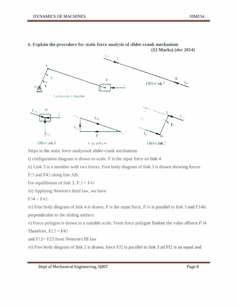
6. Explain the procedure for static force analysis of slider-crank mechanism
(12 Marks) (dec 2014)
Steps in the static force analysisof slider-crank mechanism
i) configuration diagram is drawn to scale. F is the input force on link 4
ii) Link 3 is a member with two forces. Free body diagram of link 3 is drawn showing forces
F:3 and F43 along line AB.
For equilibrium of link 3, F:3 = F4J
iii) Applying Newton's third law, we have
F34 = F43
iv) Free body diagram of link 4 is drawn. F is the input force, F34 is parallel to link 3 and F14is
perpendicular to the sliding surface.
v) Force polygon is drawn to a suitable scale. From force polygon findout the value afforce F34
Therefore, F23 = F43
and F12= F23 from Newton's III law
vi) Free body diagram of link 2 is drawn. force FJ2 is parallel to link 3 ad FI2 is an equal and
DYNAMICS OF MACHINES 10ME54
Dept of Mechanical Engineering, SJBIT Page 9
7. Explain principle of virtual work application to static force analysis
(06 Marks) (June13)
Another approach to force - analysis is based on the principle of virtual (imaginary) work. This
method is based on an energy balance of the system, which requires that the net change in
internal energy of a system during small displacement must be equal to the difference between
the work input to the system and the work output including the work dine against friction, if
any, Therefore if a system which is in equilibrium under the action of difference forces, is given
a small displacement from equilibrium, then the net change in the internal energy will be equal
will be equal to the work done on the system. In short the principle of virtual work can be stated
as "The work done during virtual displacement from the equilibrium is equal to zero.
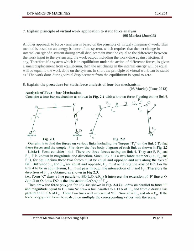
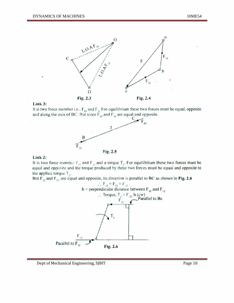
8. Explain the procedure for static force analysis of four bar mechanism.
(08 Marks) (June 2013)
DYNAMICS OF MACHINES 10ME54
Dept of Mechanical Engineering, SJBIT Page 10
DYNAMICS OF MACHINES 10ME54
Dept of Mechanical Engineering, SJBIT Page 11
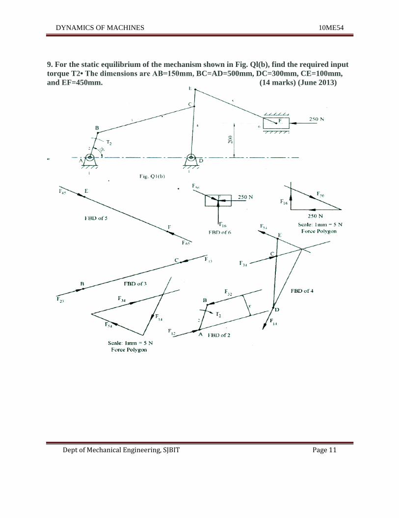
9. For the static equilibrium of the mechanism shown in Fig. Ql(b), find the required input
torque T2• The dimensions are AB=150mm, BC=AD=500mm, DC=300mm, CE=100mm,
and EF=450mm. (14 marks) (June 2013)
DYNAMICS OF MACHINES 10ME54
Dept of Mechanical Engineering, SJBIT Page 12
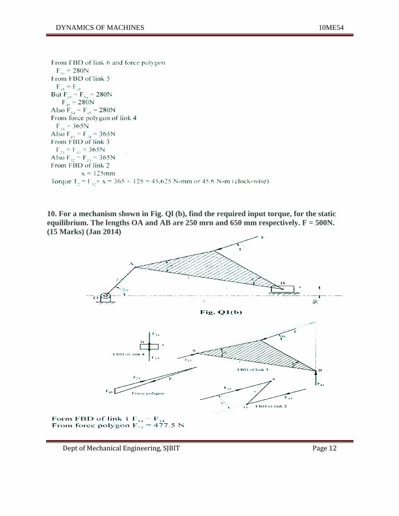
10. For a mechanism shown in Fig. Ql (b), find the required input torque, for the static
equilibrium. The lengths OA and AB are 250 mrn and 650 mm respectively. F = 500N.
(15 Marks) (Jan 2014)
DYNAMICS OF MACHINES 10ME54
Dept of Mechanical Engineering, SJBIT Page 13
F32= F23= 477.5N
From BD of link 2
x=144mm
Torque on link 2
T2 = F32X X = 477.5144=68.76 N-m
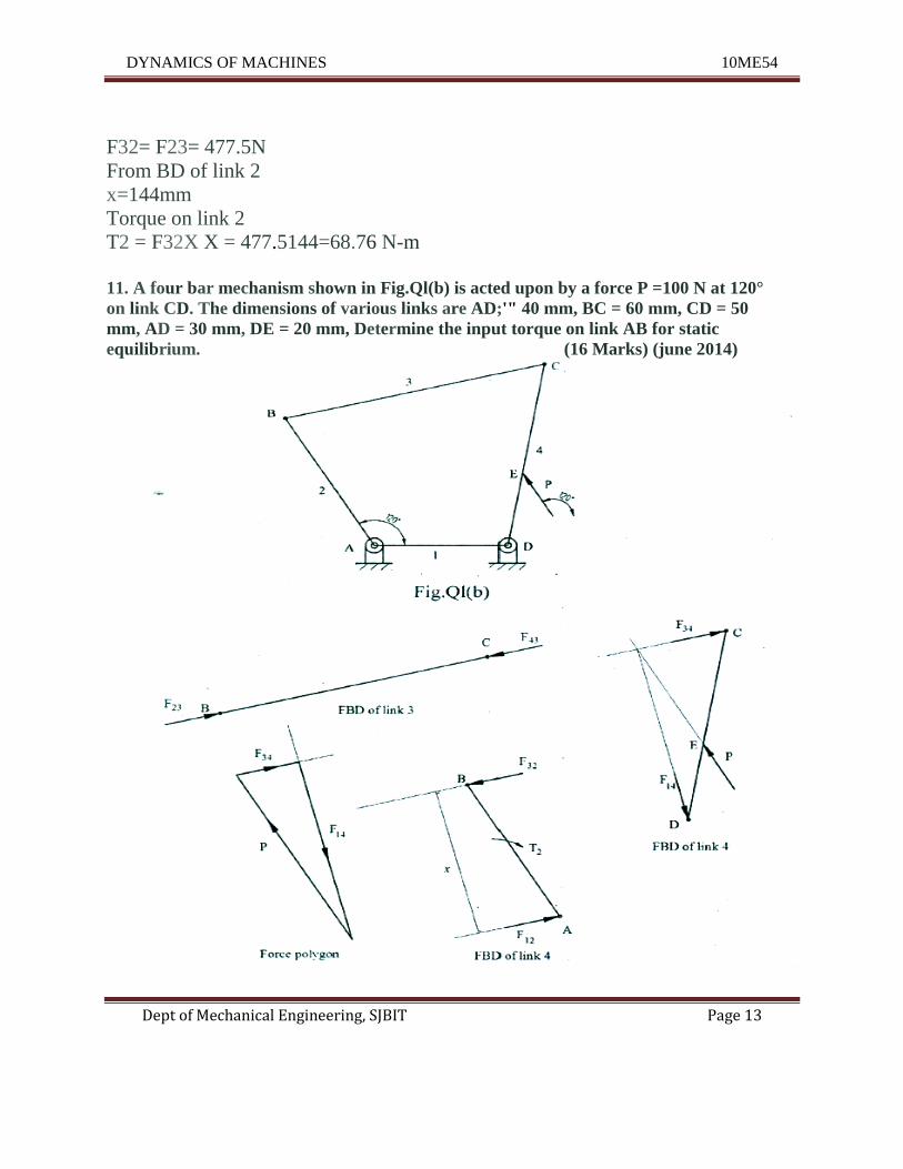
11. A four bar mechanism shown in Fig.Ql(b) is acted upon by a force P =100 N at 120°
on link CD. The dimensions of various links are AD;'" 40 mm, BC = 60 mm, CD = 50
mm, AD = 30 mm, DE = 20 mm, Determine the input torque on link AB for static
equilibrium. (16 Marks) (june 2014)
DYNAMICS OF MACHINES 10ME54
Dept of Mechanical Engineering, SJBIT Page 14
From FBD of link 3 F23= F43
From force polygon
'F'4 ~ 96.2N
F34= 27.7N
F43= F34= 27.7N
and F23= Fn = 27.7N
From FBD of link 4 x = 38.5 mm
Torque on link 2, T2 = F32X X = 27.738.5 = ·1066.45 N.mm(cw)
DYNAMICS OF MACHINES 10ME54
Dept of Mechanical Engineering, SJBIT Page 15
UNIT – 2
Dynamic Force Analysis
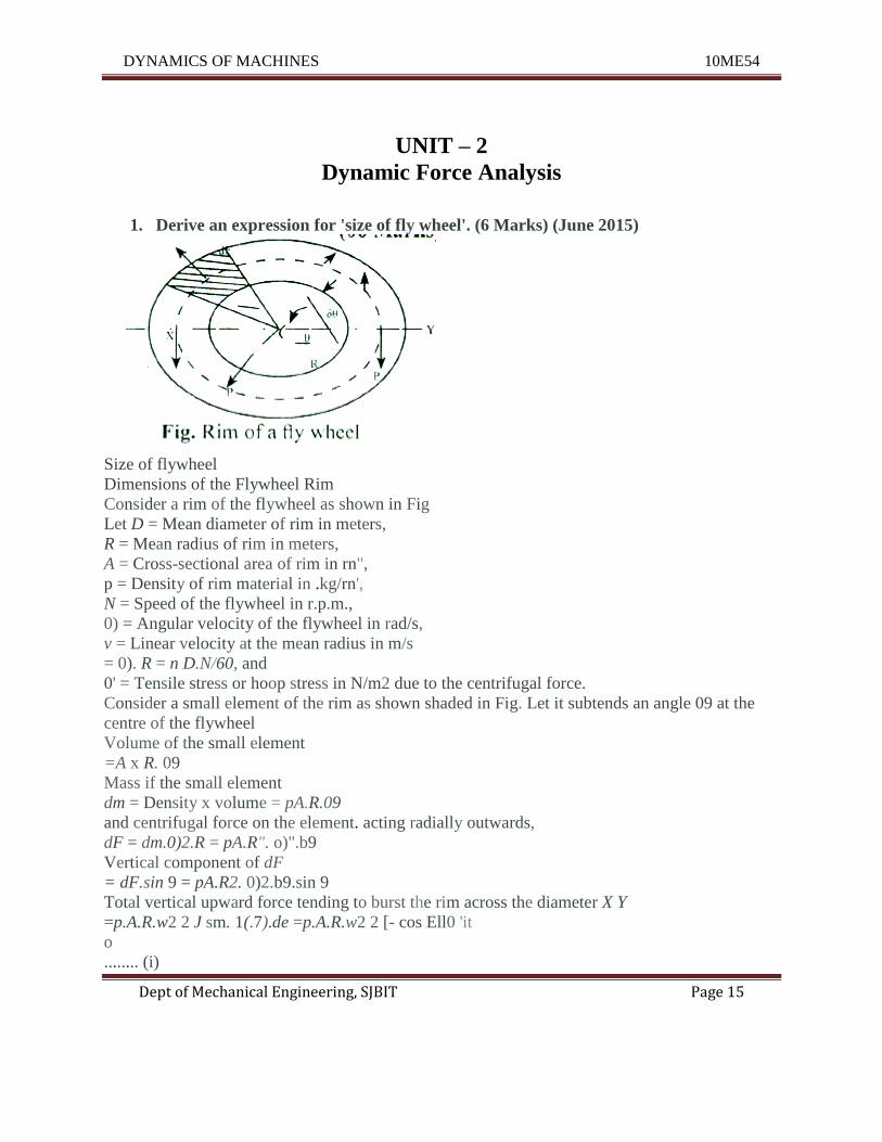
1. Derive an expression for 'size of fly wheel'. (6 Marks) (June 2015)
Size of flywheel
Dimensions of the Flywheel Rim
Consider a rim of the flywheel as shown in Fig
Let D = Mean diameter of rim in meters,
R = Mean radius of rim in meters,
A = Cross-sectional area of rim in rn",
p = Density of rim material in .kg/rn',
N = Speed of the flywheel in r.p.m.,
0) = Angular velocity of the flywheel in rad/s,
v = Linear velocity at the mean radius in m/s
= 0). R = n D.N/60, and
0' = Tensile stress or hoop stress in N/m2 due to the centrifugal force.
Consider a small element of the rim as shown shaded in Fig. Let it subtends an angle 09 at the
centre of the flywheel
Volume of the small element
=A x R. 09
Mass if the small element
dm = Density x volume = pA.R.09
and centrifugal force on the element. acting radially outwards,
dF = dm.0)2.R = pA.R". o)".b9
Vertical component of dF
= dF.sin 9 = pA.R2. 0)2.b9.sin 9
Total vertical upward force tending to burst the rim across the diameter X Y
=p.A.R.w2 2 J sm. 1(.7).de =p.A.R.w2 2 [- cos Ell0 'it
o
........ (i)
DYNAMICS OF MACHINES 10ME54
Dept of Mechanical Engineering, SJBIT Page 16
This vertical upward force will produce tensile stress or hoop stress (also called centrifugal
stress or circumferential stress), and it is resisted by 2P, such that
2P = 20'A (ii)
Equating.equations (i) and (ii),
2.pA.R2• 0)2= 20'A
O'=- p.A.R2. 0)2= p.v' (v = O).R)
V =if (ii'1
We know that mass of the rim,
m = Volume x density = 1tD.A.p
A=~
71.D.p ....... (iv)
From equations (Ui) and (iv), we may find the value of the mean radius and cross-sectional
area of the rim.
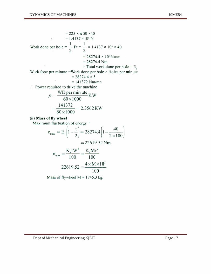
2. A punching machine is required to punch 5 holes per minute of 50 mm diameter in
40 mmthick plate. The ultimate shear strength of plate material of 22 5 MPa. The
punch hasastroke of 100 mm. Find the power of motor required of mean speed of
flywheel is 18 mls. If coefficient of fluctuation of speed is 4%, find mass of the
flywheel. (14 Marks)(June 2015)
s = 100 mm 't = 225 Nzmm? u
d = 50 mm t = 40mm v = 18 m/sec
K =4% s
(i) Power of motor
shearing force F = shearing stress x sheared area
= r x ndt
DYNAMICS OF MACHINES 10ME54
Dept of Mechanical Engineering, SJBIT Page 17
DYNAMICS OF MACHINES 10ME54
Dept of Mechanical Engineering, SJBIT Page 18
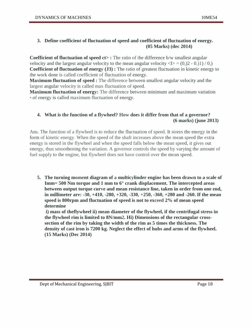
3. Define coefficient of fluctuation of speed and coefficient of fluctuation of energy.
(05 Marks) (dec 2014)
Coefficient of fluctuation of speed ct> : The ratio of the difference b/w smallest angular
velocity and the largest angular velocity to the mean angular velocity <I> = (0,)2 - 0,)1) / 0,)
Coefficient of fluctuation of energy (J3) : The ratio of greatest fluctuation in kinetic energy to
the work done is called coefficient of fluctuation of energy.
Maximum fluctuation of speed : The difference between smallest angular velocity and the
largest angular velocity is called max fluctuation of speed.
Maximum fluctuation of energy: The difference between minimum and maximum variation
•.of energy is called maximum fluctuation of energy.
4. What is the function of a flywheel? How does it differ from that of a governor?
(6 marks) (june 2013)
Ans. The function of a flywheel is to reduce the fluctuation of speed. It stores the energy in the
form of kinetic energy. When the speed of the shaft increases above the mean speed the extra
energy is stored in the flywheel and when the speed falls below the mean speed, it gives out
energy, thus smoothening the variation. A governor controls the speed by varying the amount of
fuel supply to the engine, but flywheel does not have control over the mean speed.
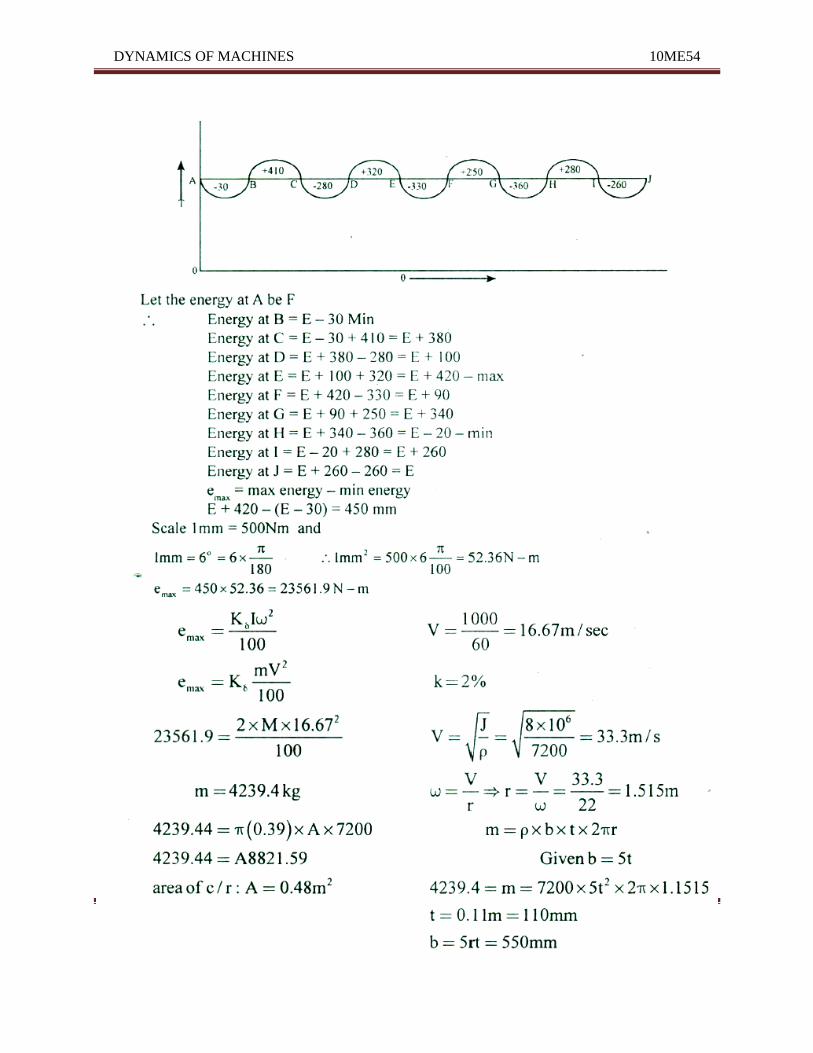
5. The turning moment diagram of a multicylinder engine has been drawn to a scale of
Imm= 500 Nm torque and 1 mm to 6° crank displacement. The intercepted areas
between output torque curve and mean resistance line, taken in order from one end,
in millimeter are: -30, +410, -280, +320, -330, +250, -360, +280 and -260. If the mean
speed is 800rpm and fluctuation of speed is not to exceed 2% of mean speed
determine
i) mass of theflywheel ii) mean diameter of the flywheel, if the centrifugal stress in
the flywheel rim is limited to 8N/mm2. Hi) Dimensions of the rectangular cross-
section of the rim by taking the width of the rim as 5 times the thickness. The
density of cast iron is 7200 kg. Neglect the effect of hubs and arms of the flywheel.
(15 Marks) (Dec 2014)
DYNAMICS OF MACHINES 10ME54
Dept of Mechanical Engineering, SJBIT Page 19
DYNAMICS OF MACHINES 10ME54
Dept of Mechanical Engineering, SJBIT Page 20
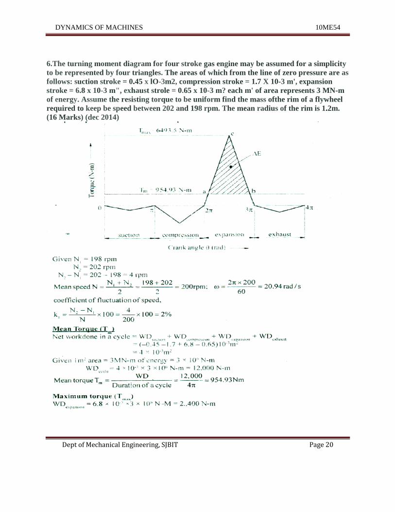
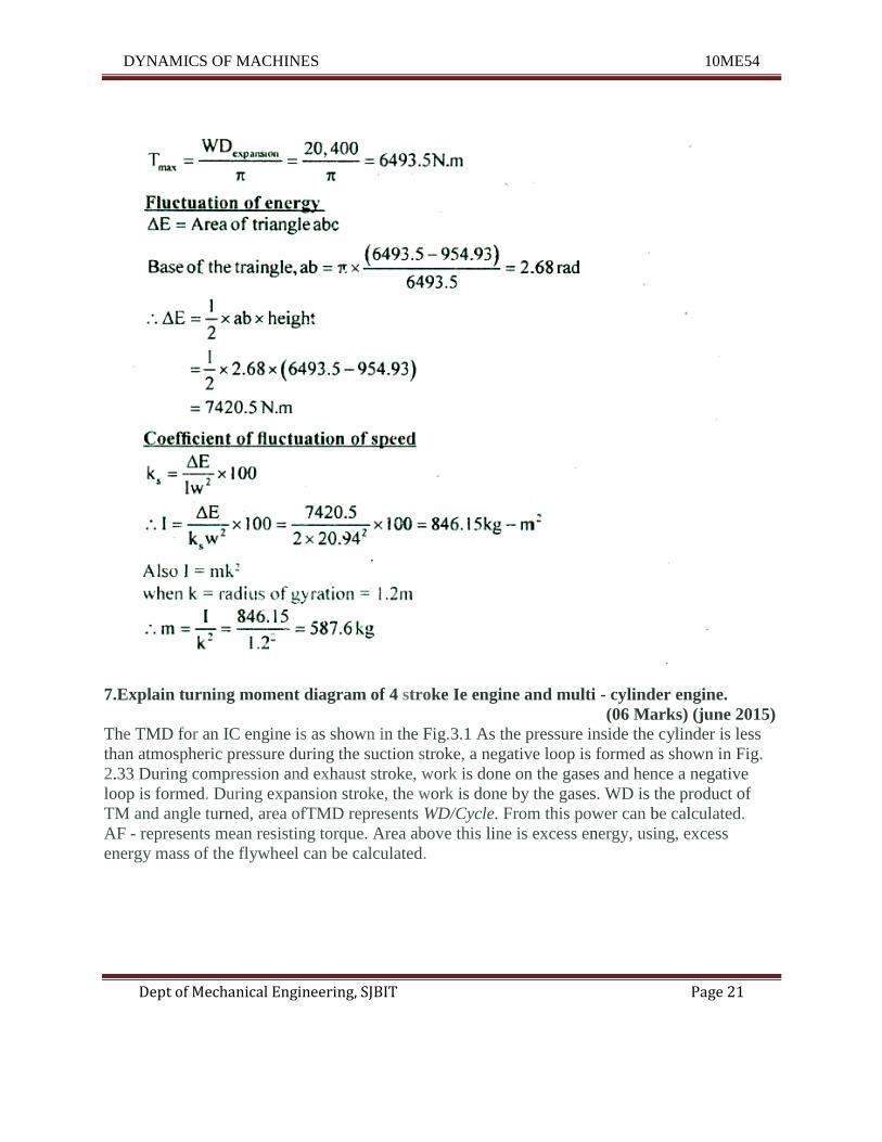
6.The turning moment diagram for four stroke gas engine may be assumed for a simplicity
to be represented by four triangles. The areas of which from the line of zero pressure are as
follows: suction stroke = 0.45 x lO-3m2, compression stroke = 1.7 X 10⁻³ m', expansion
stroke = 6.8 x 10⁻³ m", exhaust strole = 0.65 x 10⁻³ m? each m' of area represents 3 MN-m
of energy. Assume the resisting torque to be uniform find the mass ofthe rim of a flywheel
required to keep be speed between 202 and 198 rpm. The mean radius of the rim is 1.2m.
(16 Marks) (dec 2014)
DYNAMICS OF MACHINES 10ME54
Dept of Mechanical Engineering, SJBIT Page 21
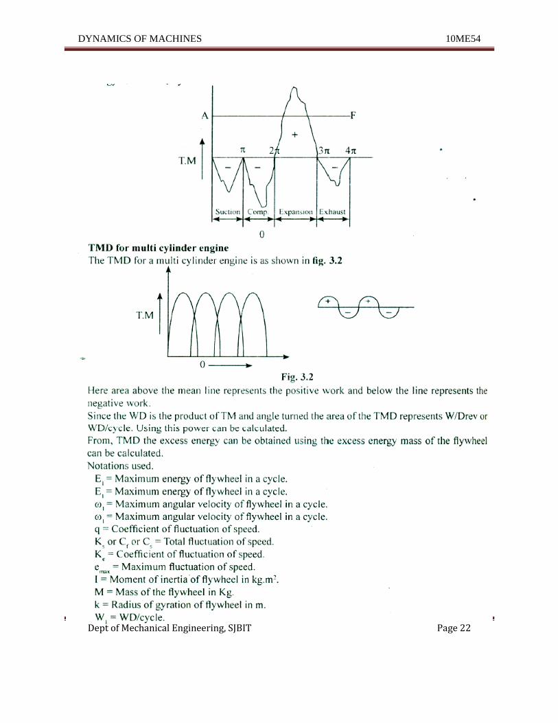
7.Explain turning moment diagram of 4 stroke Ie engine and multi - cylinder engine.
(06 Marks) (june 2015)
The TMD for an IC engine is as shown in the Fig.3.1 As the pressure inside the cylinder is less
than atmospheric pressure during the suction stroke, a negative loop is formed as shown in Fig.
2.33 During compression and exhaust stroke, work is done on the gases and hence a negative
loop is formed. During expansion stroke, the work is done by the gases. WD is the product of
TM and angle turned, area ofTMD represents WD/Cycle. From this power can be calculated.
AF - represents mean resisting torque. Area above this line is excess energy, using, excess
energy mass of the flywheel can be calculated.
DYNAMICS OF MACHINES 10ME54
Dept of Mechanical Engineering, SJBIT Page 22
DYNAMICS OF MACHINES 10ME54
Dept of Mechanical Engineering, SJBIT Page 23
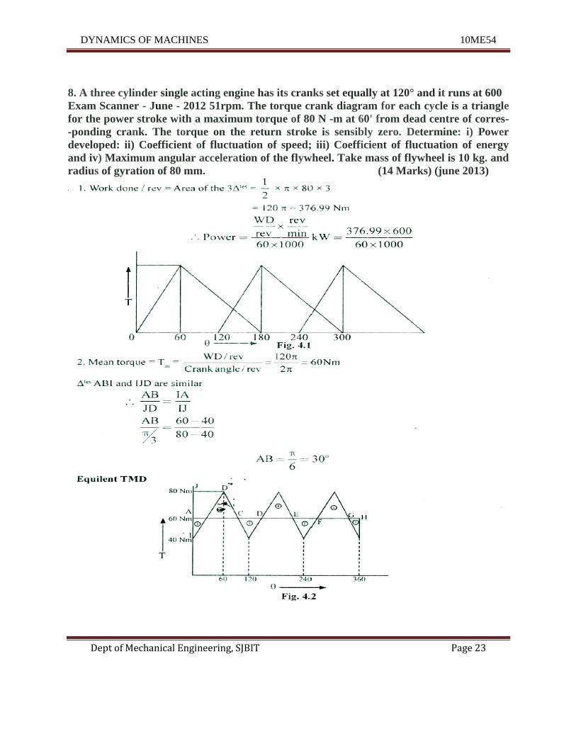
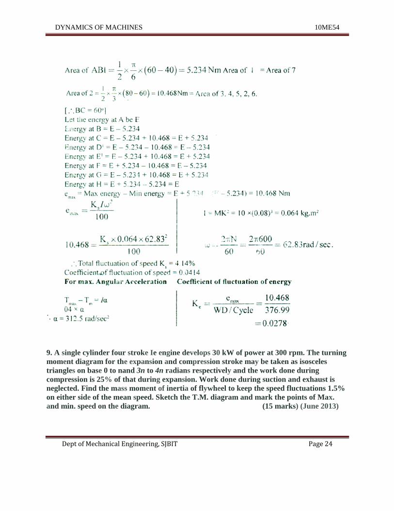
8. A three cylinder single acting engine has its cranks set equally at 120° and it runs at 600
Exam Scanner - June - 2012 51rpm. The torque crank diagram for each cycle is a triangle
for the power stroke with a maximum torque of 80 N -m at 60' from dead centre of corres-
-ponding crank. The torque on the return stroke is sensibly zero. Determine: i) Power
developed: ii) Coefficient of fluctuation of speed; iii) Coefficient of fluctuation of energy
and iv) Maximum angular acceleration of the flywheel. Take mass of flywheel is 10 kg. and
radius of gyration of 80 mm. (14 Marks) (june 2013)
DYNAMICS OF MACHINES 10ME54
Dept of Mechanical Engineering, SJBIT Page 24
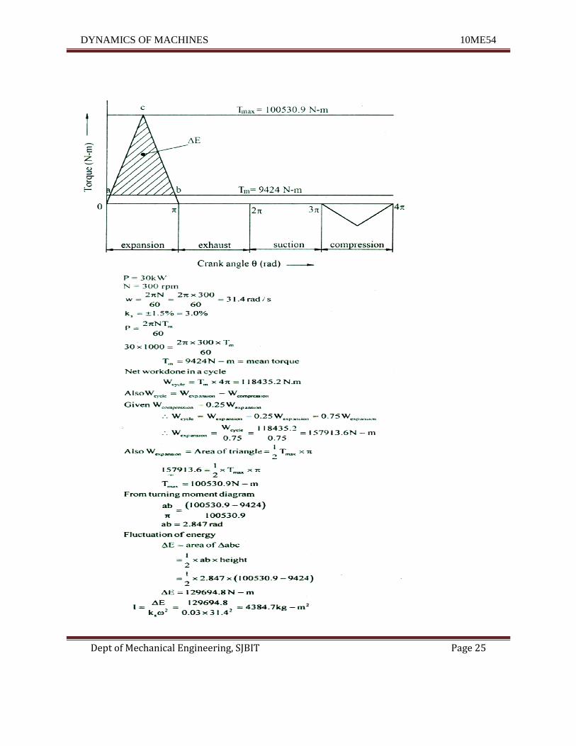
9. A single cylinder four stroke Ie engine develops 30 kW of power at 300 rpm. The turning
moment diagram for the expansion and compression stroke may be taken as isosceles
triangles on base 0 to nand 3n to 4n radians respectively and the work done during
compression is 25% of that during expansion. Work done during suction and exhaust is
neglected. Find the mass moment of inertia of flywheel to keep the speed fluctuations 1.5%
on either side of the mean speed. Sketch the T.M. diagram and mark the points of Max.
and min. speed on the diagram. (15 marks) (June 2013)
DYNAMICS OF MACHINES 10ME54
Dept of Mechanical Engineering, SJBIT Page 25
DYNAMICS OF MACHINES 10ME54
Dept of Mechanical Engineering, SJBIT Page 26
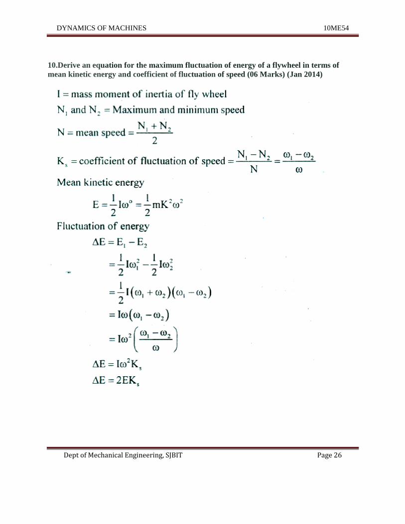
10.Derive an equation for the maximum fluctuation of energy of a flywheel in terms of
mean kinetic energy and coefficient of fluctuation of speed (06 Marks) (Jan 2014)
DYNAMICS OF MACHINES 10ME54
Dept of Mechanical Engineering, SJBIT Page 27
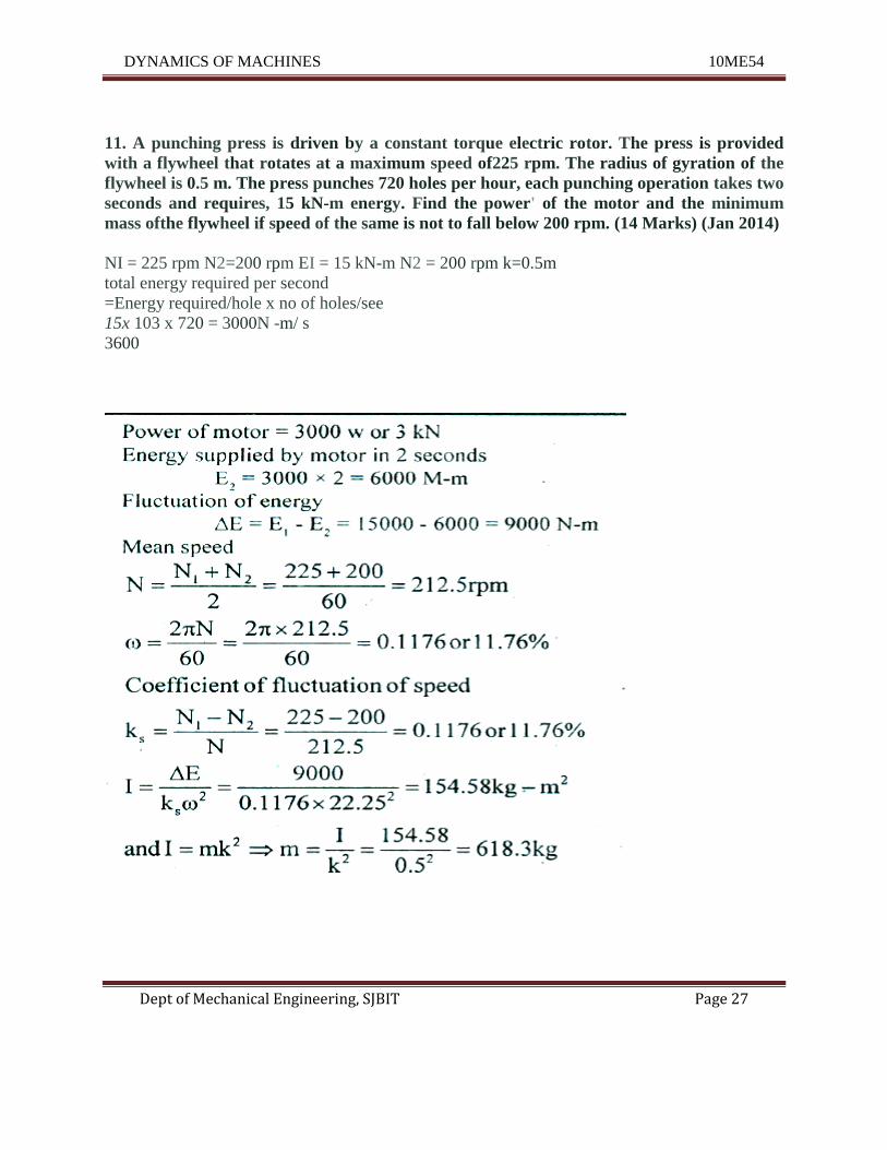
11. A punching press is driven by a constant torque electric rotor. The press is provided
with a flywheel that rotates at a maximum speed of225 rpm. The radius of gyration of the
flywheel is 0.5 m. The press punches 720 holes per hour, each punching operation takes two
seconds and requires, 15 kN-m energy. Find the power' of the motor and the minimum
mass ofthe flywheel if speed of the same is not to fall below 200 rpm. (14 Marks) (Jan 2014)
NI = 225 rpm N2=200 rpm EI = 15 kN-m N2 = 200 rpm k=0.5m
total energy required per second
=Energy required/hole x no of holes/see
15x 103 x 720 = 3000N -m/ s
3600
DYNAMICS OF MACHINES 10ME54
Dept of Mechanical Engineering, SJBIT Page 28
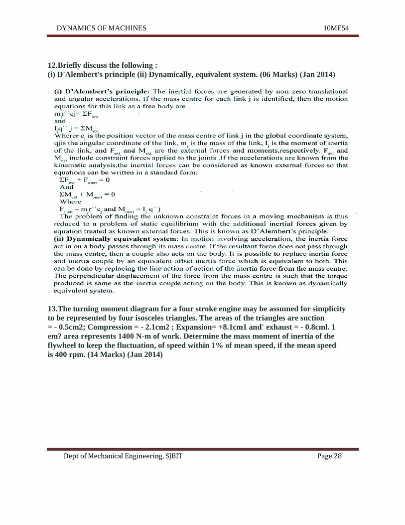
12.Briefly discuss the following :
(i) D'Alembert's principle (ii) Dynamically, equivalent system. (06 Marks) (Jan 2014)
13.The turning moment diagram for a four stroke engine may be assumed for simplicity
to be represented by four isosceles triangles. The areas of the triangles are suction
= - 0.5cm2; Compression = - 2.1cm2 ; Expansion= +8.1cm1 and' exhaust = - 0.8cml. 1
em? area represents 1400 N-m of work. Determine the mass moment of inertia of the
flywheel to keep the fluctuation, of speed within 1% of mean speed, if the mean speed
is 400 rpm. (14 Marks) (Jan 2014)
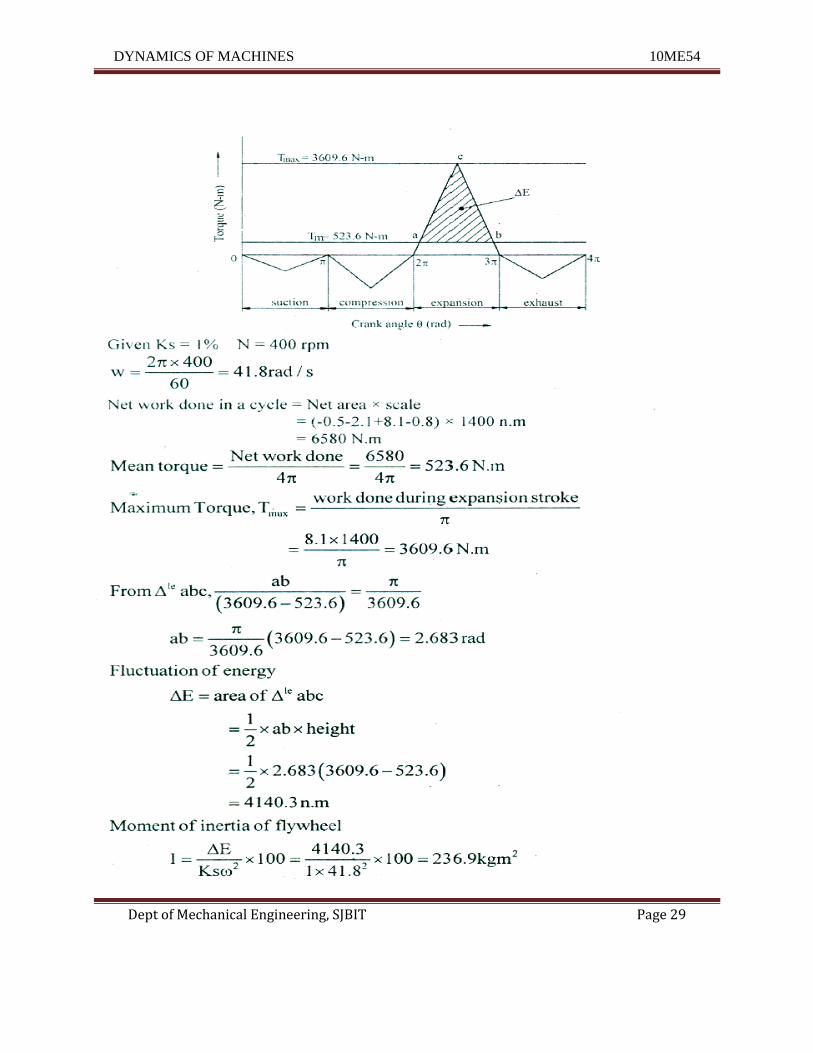
DYNAMICS OF MACHINES 10ME54
Dept of Mechanical Engineering, SJBIT Page 29
DYNAMICS OF MACHINES 10ME54
Dept of Mechanical Engineering, SJBIT Page 30
UNIT - 3
Friction and Belt Drives
1.State the laws of dynamic or kinetic friction (03 Marks) (June 2015)
Laws of Kinetic or Dynamic Friction
Following are the laws of kinetic or dynamic friction:
1. The force of friction always acts in a direction, opposite to that in which the body is moving.
2. The magnitude of the kinetic friction bear a constant ratio to the normal reaction between the
two surfaces. But this ratio is slightly less than that in case of limiting friction.
3. For moderate speeds, the force of friction remains constant. But it decreases slightly with the
increase of speed.
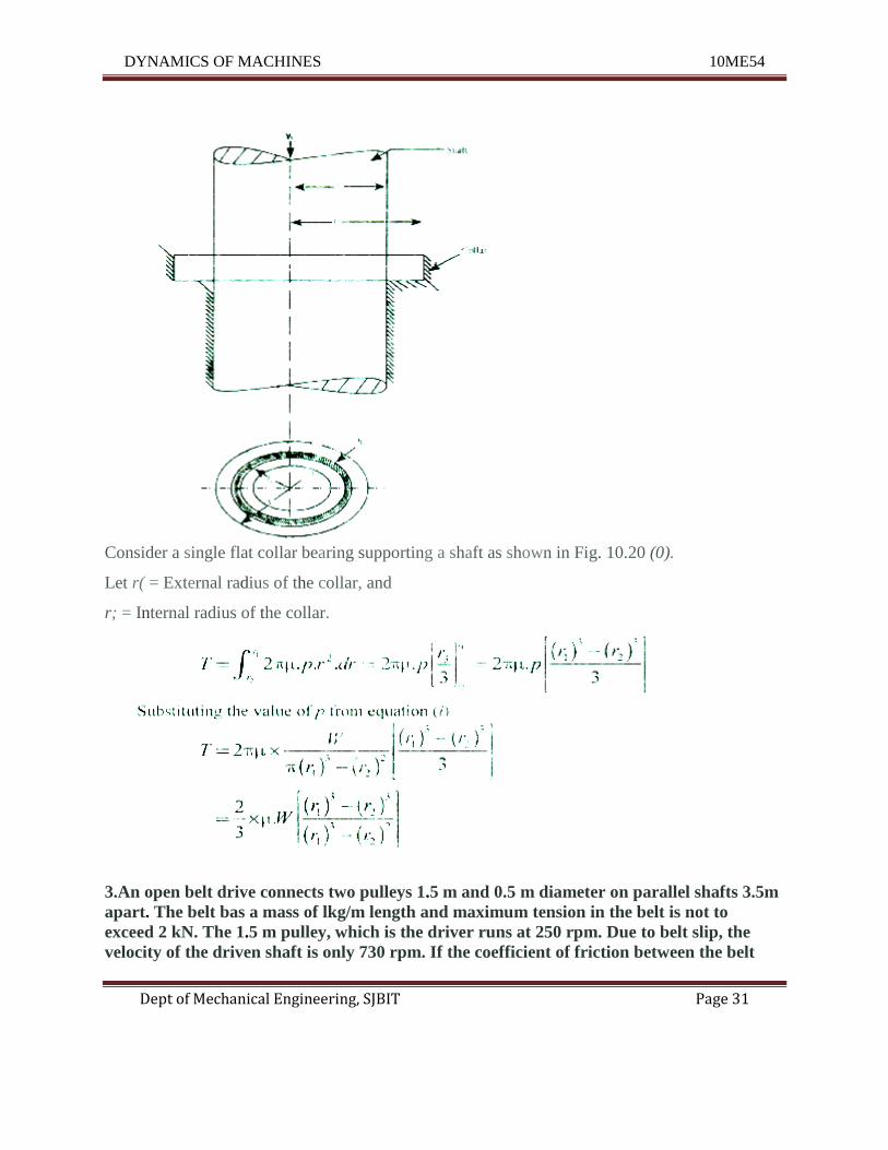
2.Derive an expression for frictional torque in a single collar bearing assuming uniform
pressure. (5 marks) (June 2015)
Single collar bearing:
DYNAMICS OF MACHINES 10ME54
Dept of Mechanical Engineering, SJBIT Page 31
Consider a single flat collar bearing supporting a shaft as shown in Fig. 10.20 (0).
Let r( = External radius of the collar, and
r; = Internal radius of the collar.
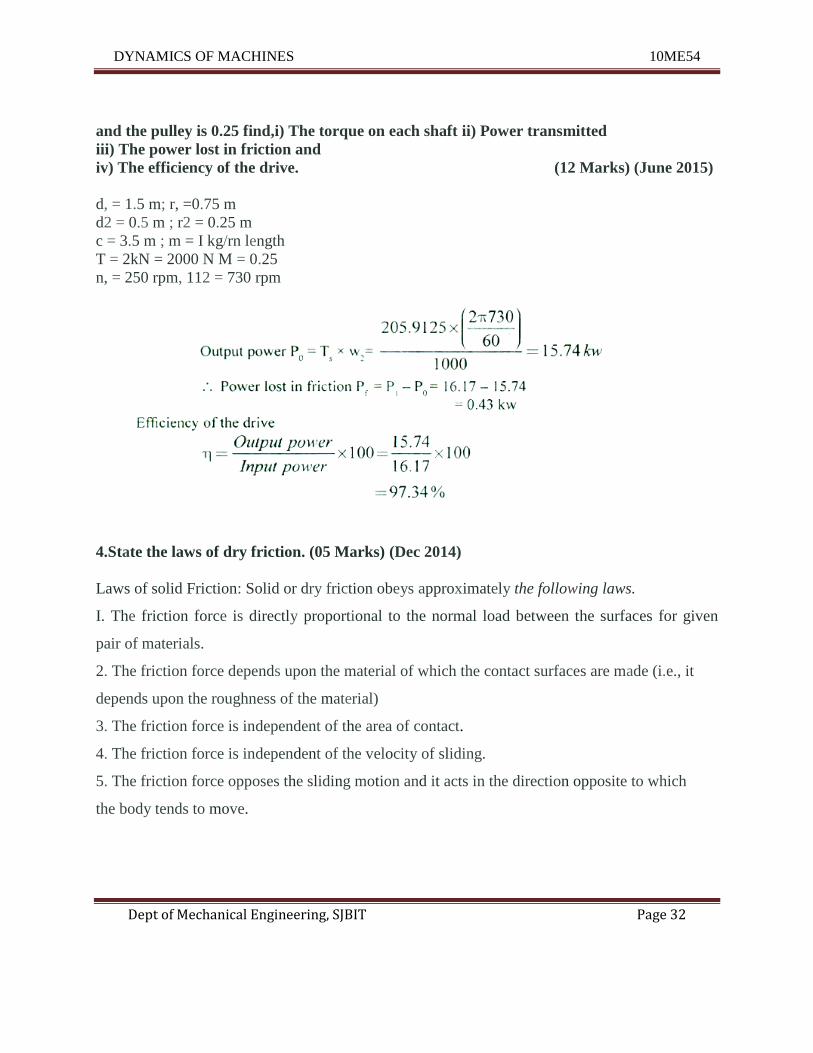
3.An open belt drive connects two pulleys 1.5 m and 0.5 m diameter on parallel shafts 3.5m
apart. The belt bas a mass of lkg/m length and maximum tension in the belt is not to
exceed 2 kN. The 1.5 m pulley, which is the driver runs at 250 rpm. Due to belt slip, the
velocity of the driven shaft is only 730 rpm. If the coefficient of friction between the belt
DYNAMICS OF MACHINES 10ME54
Dept of Mechanical Engineering, SJBIT Page 32
and the pulley is 0.25 find,i) The torque on each shaft ii) Power transmitted
iii) The power lost in friction and
iv) The efficiency of the drive. (12 Marks) (June 2015)
d, = 1.5 m; r, =0.75 m
d2 = 0.5 m ; r2 = 0.25 m
c = 3.5 m ; m = I kg/rn length
T = 2kN = 2000 N M = 0.25
n, = 250 rpm, 112 = 730 rpm
4.State the laws of dry friction. (05 Marks) (Dec 2014)
Laws of solid Friction: Solid or dry friction obeys approximately the following laws.
I. The friction force is directly proportional to the normal load between the surfaces for given
pair of materials.
2. The friction force depends upon the material of which the contact surfaces are made (i.e., it
depends upon the roughness of the material)
3. The friction force is independent of the area of contact.
4. The friction force is independent of the velocity of sliding.
5. The friction force opposes the sliding motion and it acts in the direction opposite to which
the body tends to move.
DYNAMICS OF MACHINES 10ME54
Dept of Mechanical Engineering, SJBIT Page 33
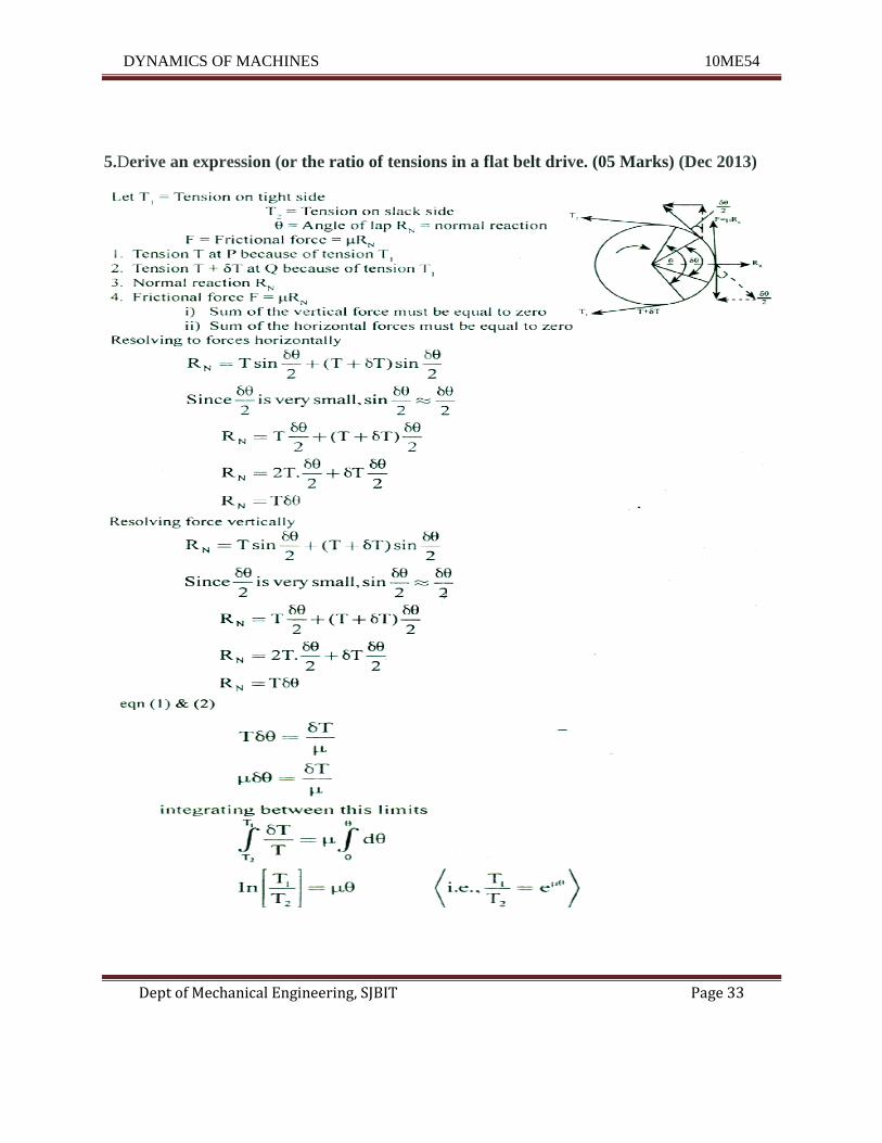
5.Derive an expression (or the ratio of tensions in a flat belt drive. (05 Marks) (Dec 2013)
DYNAMICS OF MACHINES 10ME54
Dept of Mechanical Engineering, SJBIT Page 34
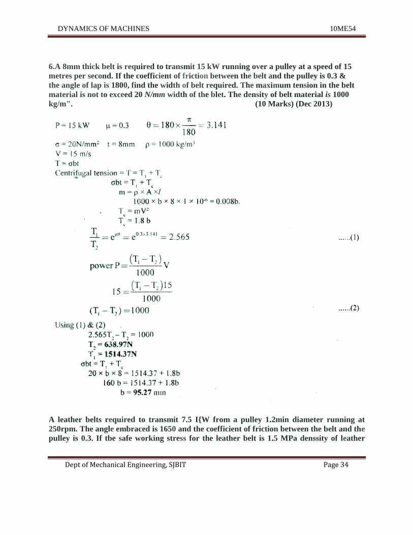
6.A 8mm thick belt is required to transmit 15 kW running over a pulley at a speed of 15
metres per second. If the coefficient of friction between the belt and the pulley is 0.3 &
the angle of lap is 1800, find the width of belt required. The maximum tension in the belt
material is not to exceed 20 N/mm width of the blet. The density of belt material is 1000
kg/m". (10 Marks) (Dec 2013)
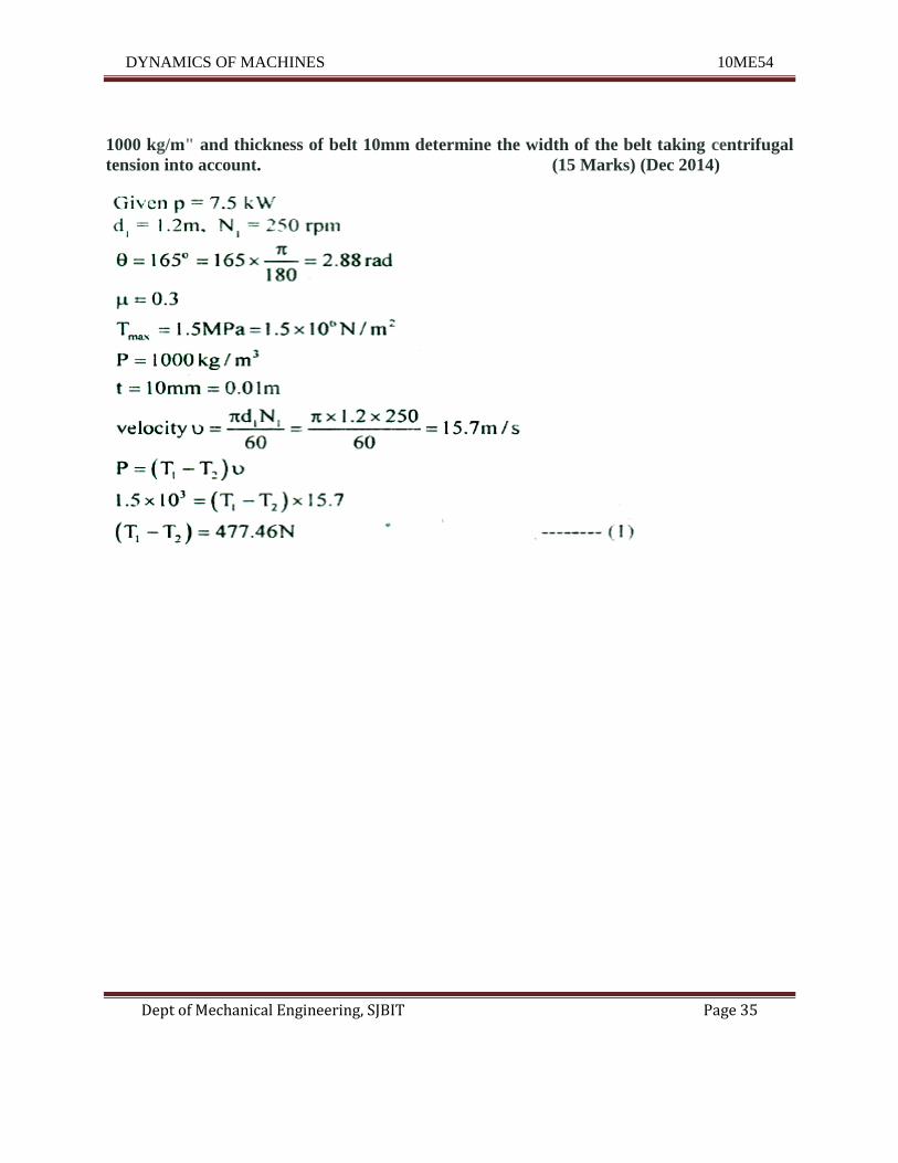
A leather belts required to transmit 7.5 I{W from a pulley 1.2min diameter running at
250rpm. The angle embraced is 1650 and the coefficient of friction between the belt and the
pulley is 0.3. If tbe safe working stress for the leather belt is 1.5 MPa denssity of leather
DYNAMICS OF MACHINES 10ME54
Dept of Mechanical Engineering, SJBIT Page 35
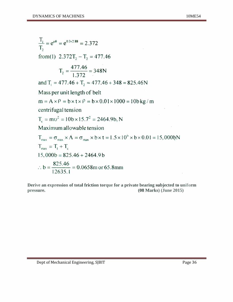
1000 kg/m" and thickness of belt 10mm determine the width of the belt taking centrifugal
tension into account. (15 Marks) (Dec 2014)
DYNAMICS OF MACHINES 10ME54
Dept of Mechanical Engineering, SJBIT Page 36
Derive an expression of total friction torque for a private bearing subjected to uniform
pressure. (08 Marks) (June 2015)
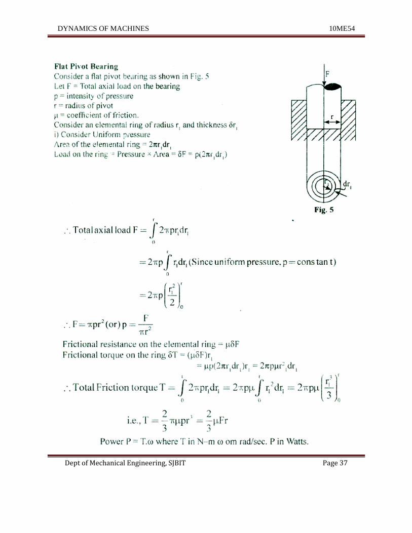
DYNAMICS OF MACHINES 10ME54
Dept of Mechanical Engineering, SJBIT Page 37
DYNAMICS OF MACHINES 10ME54
Dept of Mechanical Engineering, SJBIT Page 38
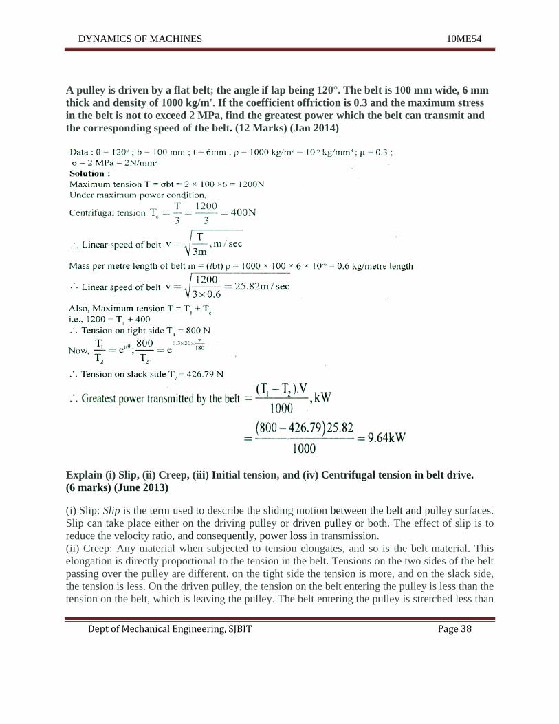
A pulley is driven by a flat belt; the angle if lap being 120°. The belt is 100 mm wide, 6 mm
thick and density of 1000 kg/m'. If the coefficient offriction is 0.3 and the maximum stress
in the belt is not to exceed 2 MPa, find the greatest power which the belt can transmit and
the corresponding speed of the belt. (12 Marks) (Jan 2014)
Explain (i) Slip, (ii) Creep, (iii) Initial tension, and (iv) Centrifugal tension in belt drive.
(6 marks) (June 2013)
(i) Slip: Slip is the term used to describe the sliding motion between the belt and pulley surfaces.
Slip can take place either on the driving pulley or driven pulley or both. The effect of slip is to
reduce the velocity ratio, and consequently, power loss in transmission.
(ii) Creep: Any material when subjected to tension elongates, and so is the belt material. This
elongation is directly proportional to the tension in the belt. Tensions on the two sides of the belt
passing over the pulley are different. on the tight side the tension is more, and on the slack side,
the tension is less. On the driven pulley, the tension on the belt entering the pulley is less than the
tension on the belt, which is leaving the pulley. The belt entering the pulley is stretched less than
DYNAMICS OF MACHINES 10ME54
Dept of Mechanical Engineering, SJBIT Page 39
the belt that is leaving the pulley. Hence, there is a gradual increase in the length of belt over the
surface of the pulley. This stretching results in relative motion between the belt and pulley
surfaces. This phenomenon is called creep. A similar effect is there on the driving pulley
as well. Creep results in loss of power and decrease in velocity ratio. (Hi) Initial tension: When
the belt drive is not running, the belt is kept under tension known as initial tension. When the
drive is set into motion, the tension on the tight side of the belt increases due to friction, and that
on the slack side decreases. Assum ing that the length of belt remains the same before and after
the drive was set into operation, the increase in tension on the tight side of the belt over the initial
tension should be same as the decrease in tension on the slack side of the belt. Let To = initial
tension in the belt when the drive is not running T = increase in tension on the tight side =
decrease in tension on the slack side.
(iv) Centrifugal tension: Part of belt which is in contact with the pulley surface undergoes
circular motion. Each element of belt which undergoes this motion experiences centrifugal force
which is directed radially outwards. The effect is same on both the driver and driven pulleys and
the net result is that the belt is subjected to an extra tension called the centrifugal tension.
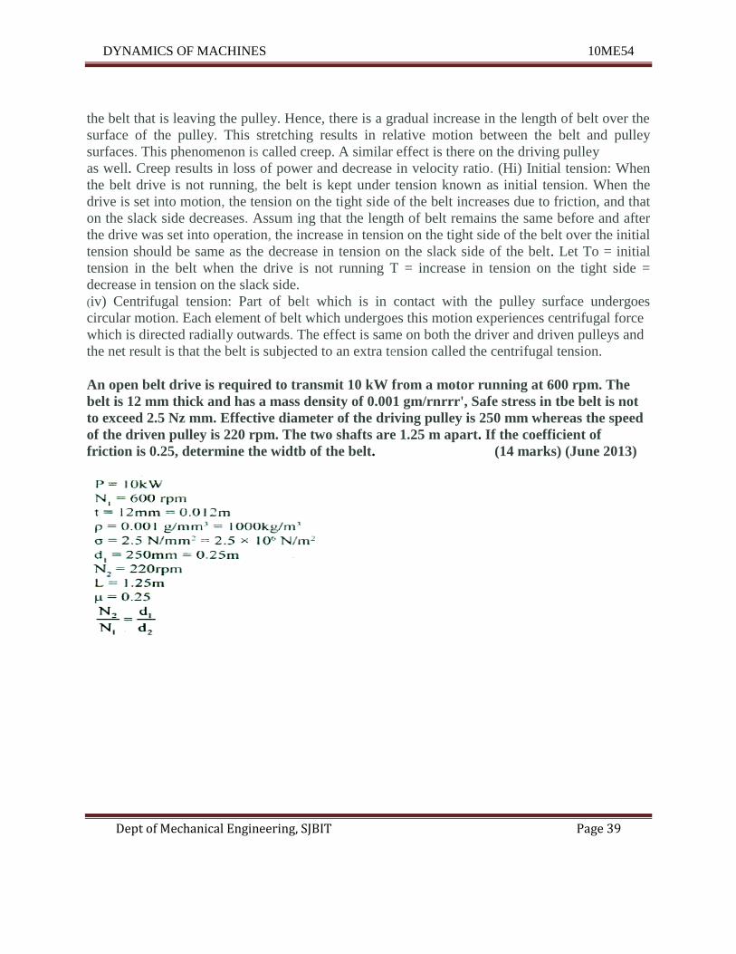
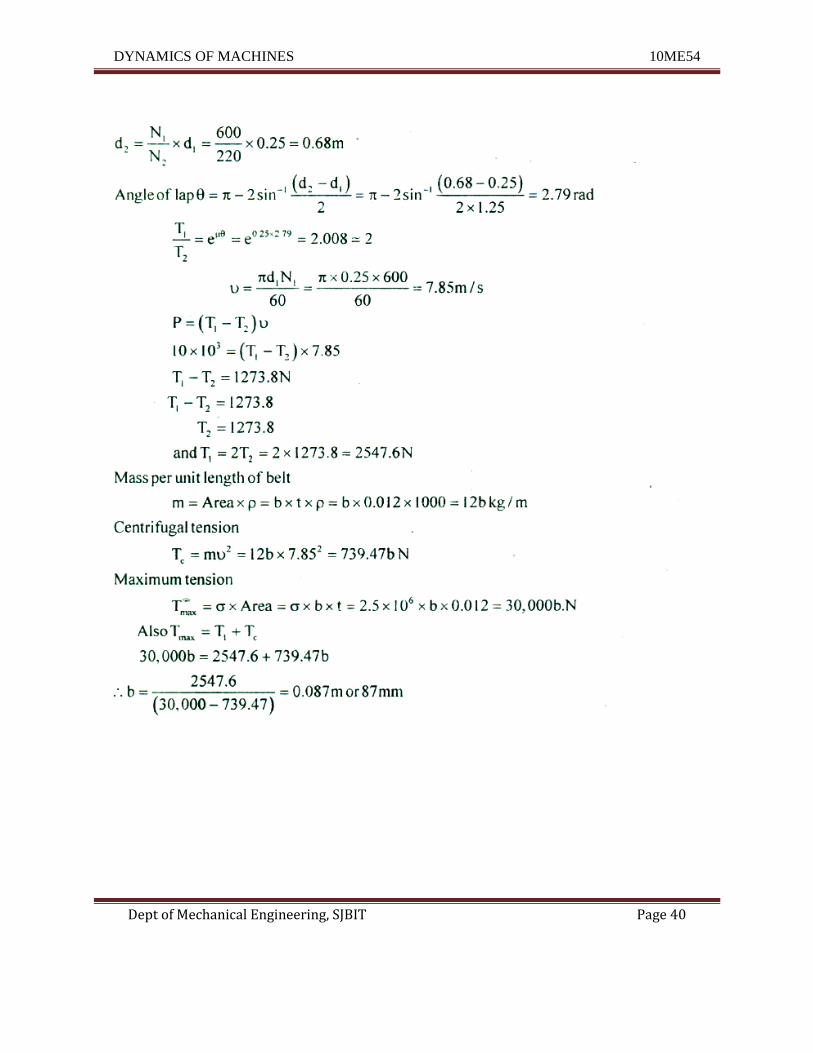
An open belt drive is required to transmit 10 kW from a motor running at 600 rpm. The
belt is 12 mm thick and has a mass density of 0.001 gm/rnrrr', Safe stress in tbe belt is not
to exceed 2.5 Nz mm. Effective diameter of the driving pulley is 250 mm whereas the speed
of the driven pulley is 220 rpm. The two shafts are 1.25 m apart. If the coefficient of
friction is 0.25, determine the widtb of the belt. (14 marks) (June 2013)
DYNAMICS OF MACHINES 10ME54
Dept of Mechanical Engineering, SJBIT Page 40
DYNAMICS OF MACHINES 10ME54
Dept of Mechanical Engineering, SJBIT Page 41
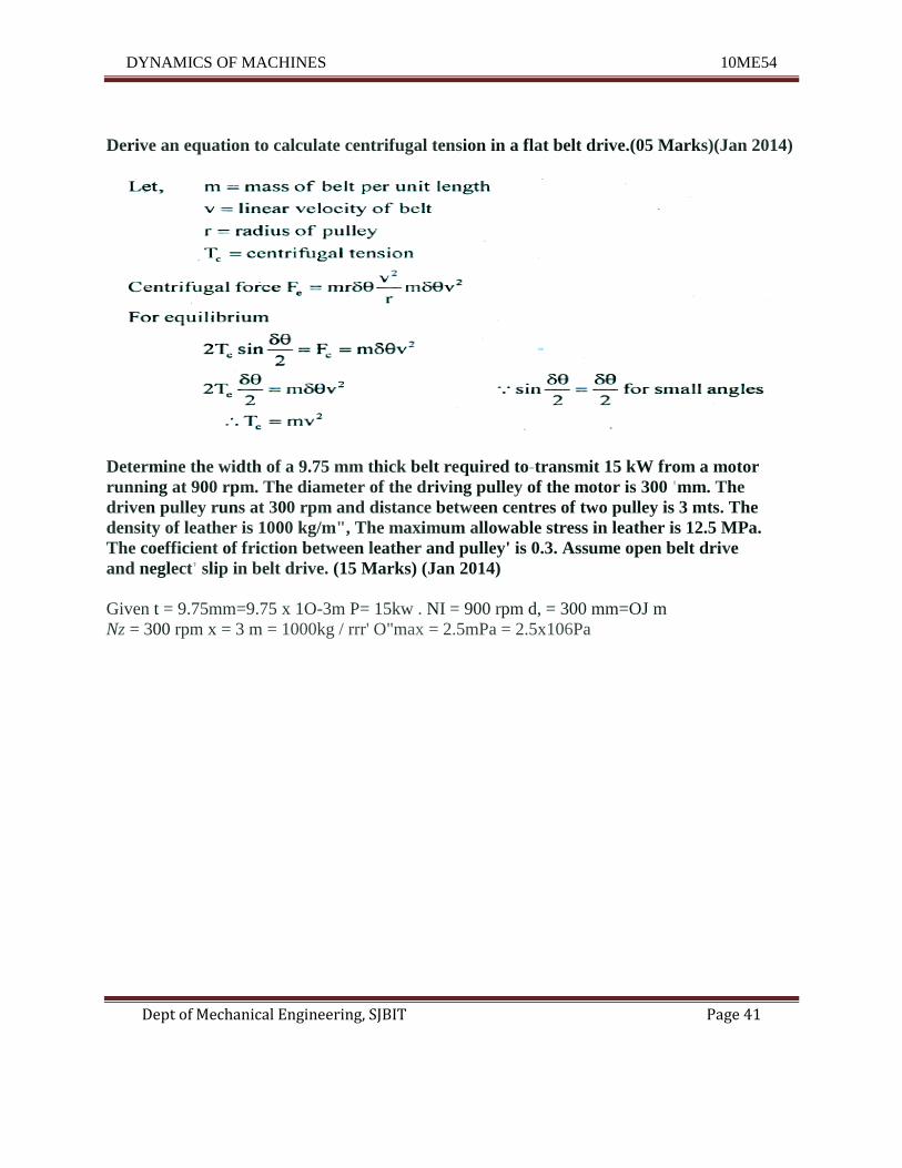
Derive an equation to calculate centrifugal tension in a flat belt drive.(05 Marks)(Jan 2014)
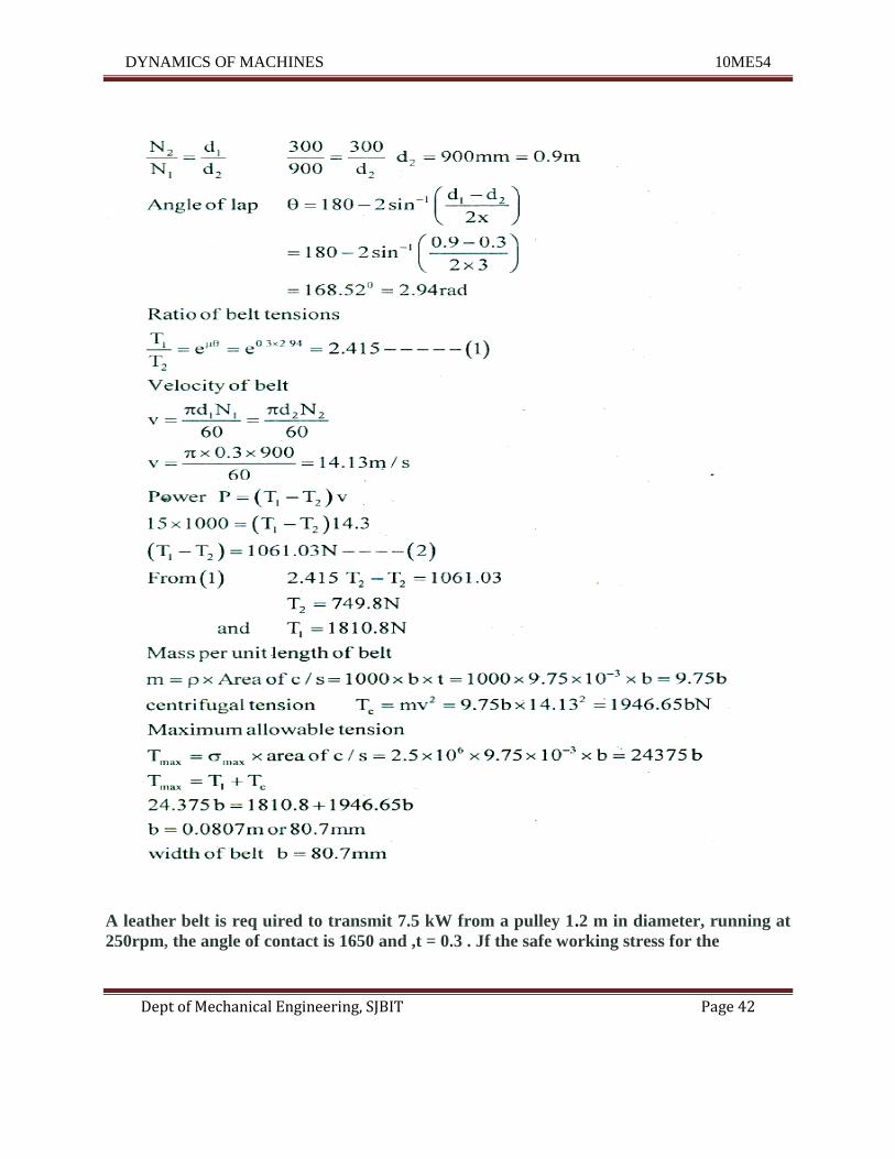
Determine the width of a 9.75 mm thick belt required to-transmit 15 kW from a motor
running at 900 rpm. The diameter of the driving pulley of the motor is 300 'mm. The
driven pulley runs at 300 rpm and distance between centres of two pulley is 3 mts. The
density of leather is 1000 kg/m", The maximum allowable stress in leather is 12.5 MPa.
The coefficient of friction between leather and pulley' is 0.3. Assume open belt drive
and neglect' slip in belt drive. (15 Marks) (Jan 2014)
Given t = 9.75mm=9.75 x 1O-3m P= 15kw . NI = 900 rpm d, = 300 mm=OJ m
Nz = 300 rpm x = 3 m = 1000kg / rrr' O"max = 2.5mPa = 2.5x10⁶Pa
DYNAMICS OF MACHINES 10ME54
Dept of Mechanical Engineering, SJBIT Page 42
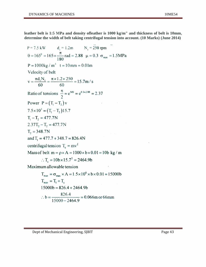
A leather belt is req uired to transmit 7.5 kW from a pulley 1.2 m in diameter, running at
250rpm, the angle of contact is 1650 and ,t = 0.3 . Jf the safe working stress for the
DYNAMICS OF MACHINES 10ME54
Dept of Mechanical Engineering, SJBIT Page 43
leather belt is 1:5 MPa and density ofleather is 1000 kg/m" and thickness of belt is 10mm,
determine the width of belt taking centrifugal tension into account. (10 Marks) (June 2014)
DYNAMICS OF MACHINES 10ME54
Dept of Mechanical Engineering, SJBIT Page 44
UNIT – 4
Balancing of Rotating Masses
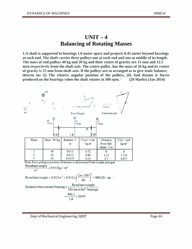
1.A shaft is supported in bearings 1.8 meter apart and projects 0.45 meter beyond bearings
at each end. The shaft carries three pulleys one at each end and one at middle of its length.
The mass of end pulleys 48 kg and 20 kg and their centre of gravity are 15 nun and 12.5
mrn respectively from the shaft axis. The centre pulley, has the mass of 56 kg and its centre
of gravity is 15 mm from shaft axis. If the pulleys are so arranged as to give static balance,
determ ine (i) The relative angular position of the pulleys, (ii) And dynam ic forces
produced on the bearings when the shaft rotates at 300 rpm. - (20 Marks) (Jan 2014)
DYNAMICS OF MACHINES 10ME54
Dept of Mechanical Engineering, SJBIT Page 45
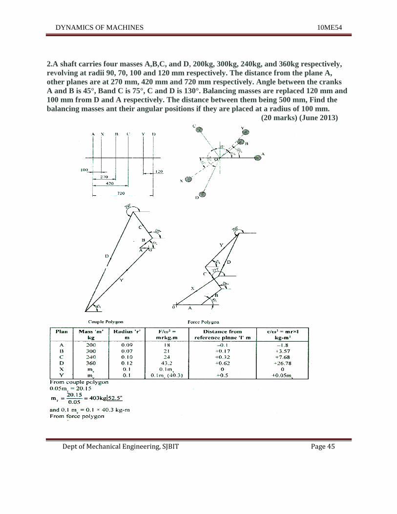
2.A shaft carries four masses A,B,C, and D, 200kg, 300kg, 240kg, and 360kg respectively,
revolving at radii 90, 70, 100 and 120 mm respectively. The distance from the plane A,
other planes are at 270 mm, 420 mm and 720 mm respectively. Angle between the cranks
A and B is 45°, Band C is 75°, C and D is 130°. Balancing masses are replaced 120 mm and
100 mm from D and A respectively. The distance between them being 500 mm, Find the
balancing masses ant their angular positions if they are placed at a radius of 100 mm.
(20 marks) (June 2013)
DYNAMICS OF MACHINES 10ME54
Dept of Mechanical Engineering, SJBIT Page 46
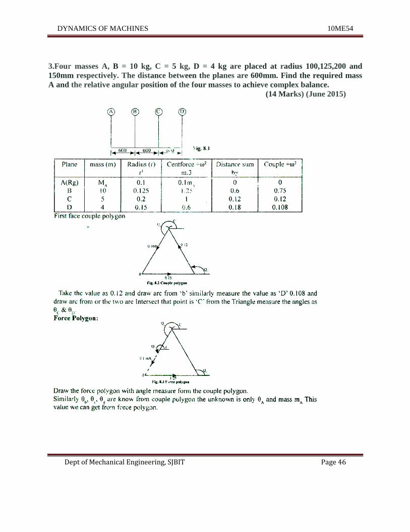
3.Four masses A, B = 10 kg, C = 5 kg, D = 4 kg are placed at radius 100,125,200 and
150mm respectively. The distance between the planes are 600mm. Find the required mass
A and the relative angular position of the four masses to achieve complex balance.
(14 Marks) (June 2015)
DYNAMICS OF MACHINES 10ME54
Dept of Mechanical Engineering, SJBIT Page 47
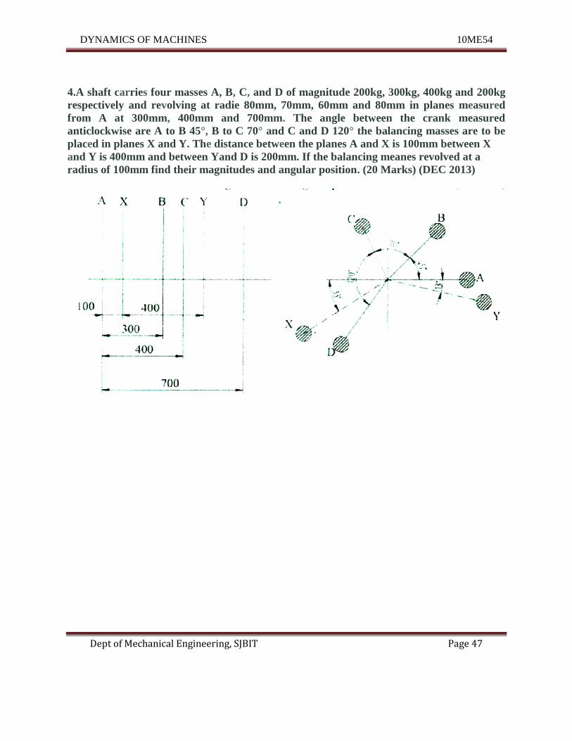
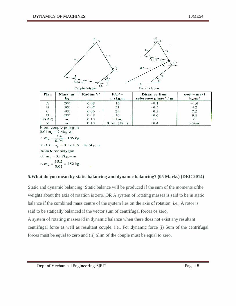
4.A shaft carries four masses A, B, C, and D of magnitude 200kg, 300kg, 400kg and 200kg
respectively and revolving at radie 80mm, 70mm, 60mm and 80mm in planes measured
from A at 300mm, 400mm and 700mm. The angle between the crank measured
anticlockwise are A to B 45°, B to C 70° and C and D 120° the balancing masses are to be
placed in planes X and Y. The distance between the planes A and X is 100mm between X
and Y is 400mm and between Yand D is 200mm. If the balancing meanes revolved at a
radius of 100mm find their magnitudes and angular position. (20 Marks) (DEC 2013)
DYNAMICS OF MACHINES 10ME54
Dept of Mechanical Engineering, SJBIT Page 48
5.What do you mean by static balancing and dynamic balancing? (05 Marks) (DEC 2014)
Static and dynamic balancing: Static balance will be produced if the sum of the moments ofthe
weights about the axis of rotation is zero. OR A system of rotating masses is said to be in static
balance if the combined mass centre of the system lies on the axis of rotation, i.e., A rotor is
said to be statically balanced if the vector sum of centrifugal forces os zero.
A system of rotating masses id in dynamic balance when there does not exist any resultant
centrifugal force as well as resultant couple. i.e., For dynamic force (i) Sum of the centrifugal
forces must be equal to zero and (ii) Slim of the couple must be equal to zero.
DYNAMICS OF MACHINES 10ME54
Dept of Mechanical Engineering, SJBIT Page 49
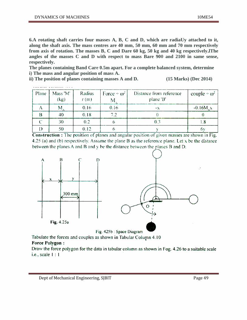
6.A rotating shaft carries four masses A, B, C and D, which are radiaUy attached to it,
along the shaft axis. The mass centres are 40 mm, 50 mm, 60 mm and 70 mm respectively
from axis of rotation. The masses B, C and Dare 60 kg, 50 kg and 40 kg respectively.lThe
angles of the masses C and D with respect to mass Bare 900 and 2100 in same sense,
respectively.
The planes containing Band Care 0.5m apart. For a complete balanced system, determine
i) The mass and angular position of mass A.
ii) The position of planes containing masses A and D. (15 Marks) (Dec 2014)
DYNAMICS OF MACHINES 10ME54
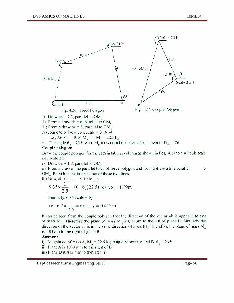
Dept of Mechanical Engineering, SJBIT Page 50
DYNAMICS OF MACHINES 10ME54
Dept of Mechanical Engineering, SJBIT Page 51
Explain the procedure for balancing several masses rotating in the same plane.
(5 marks) (June 2014)
Static balance: A system of rotating masses is said to be in static balance ifthe combined mass
center of the system lies on the axis of rotation.
Dynamic balance: A system of rotating masses is said to he in dynamic balance if there exists
neither any resultant centrifugal force nor any resultant couple when the system rotates.
Consider ant number of masses (say four) of magnitude '"I' m; mJ and m4 at distance of r., '2'
r3 and'4 from the axis of the routing shift. Let 91,92,9) and 94be the angle of these masses with
the horizontal line OX, as shown in Fig. 21.4 (a). Let these masses rotate about an axis through
o and perpendicular to the plane of paper. with a constant angular velocity of (i) rad/s.
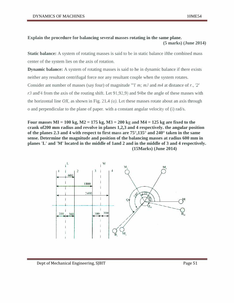
Four masses MI = 100 kg, M2 = 175 kg, M3 = 200 kg and M4 = 125 kg are fixed to the
crank of200 mm radius and revolve in planes 1,2,3 and 4 respectively. the angular position
of the planes 2.3 and 4 with respect to first mass are 75°,135° and 240° taken in the same
sense. Determine the magnitude and position of the balancing masses at radius 600 mm in
planes 'L' and 'M' located in the middle of 1and 2 and in the middle of 3 and 4 respectively.
(15Marks) (June 2014)
DYNAMICS OF MACHINES 10ME54
Dept of Mechanical Engineering, SJBIT Page 52
UNIT – 5
Balancing of Reciprocating Masses
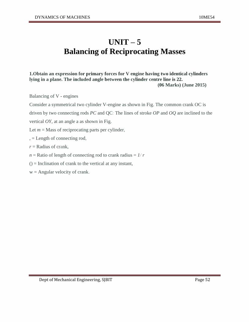
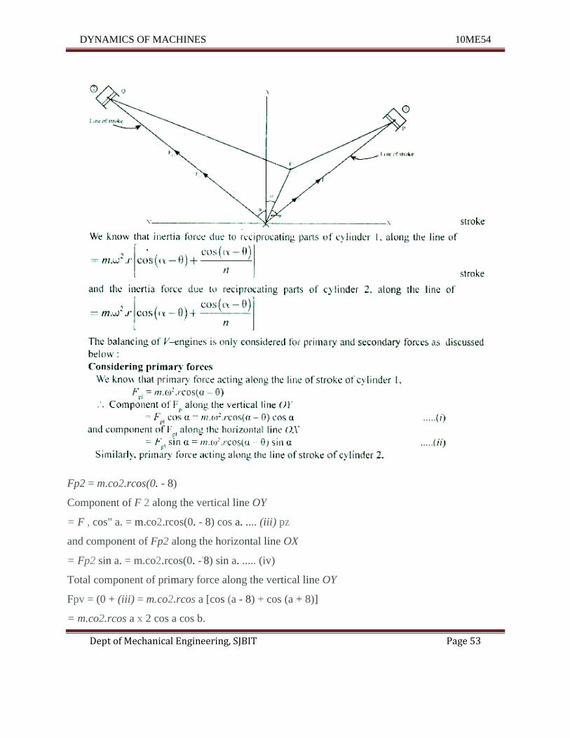
1.Obtain an expression for primary forces for V engine having two identical cylinders
lying in a plane. The included angle between the cylinder centre line is 22.
(06 Marks) (June 2015)
Balancing of V - engines
Consider a symmetrical two cylinder V-engine as shown in Fig. The common crank OC is
driven by two connecting rods PC and QC: The lines of stroke OP and OQ are inclined to the
vertical OY, at an angle a as shown in Fig.
Let m = Mass of reciprocating parts per cylinder,
, = Length of connecting rod,
r = Radius of crank,
n = Ratio of length of connecting rod to crank radius = 1/ r
() = Inclination of crank to the vertical at any instant,
w = Angular velocity of crank.
DYNAMICS OF MACHINES 10ME54
Dept of Mechanical Engineering, SJBIT Page 53
Fp2 = m.co2.rcos(0. - 8)
Component of F 2 along the vertical line OY
= F , cos" a. = m.co2.rcos(0. - 8) cos a. .... (iii) pz
and component of Fp2 along the horizontal line OX
= Fp2 sin a. = m.co2.rcos(0. -'8) sin a. ..... (iv)
Total component of primary force along the vertical line OY
Fpv = (0 + (iii) = m.co2.rcos a [cos (a - 8) + cos (a + 8)]
= m.co2.rcos a x 2 cos a cos b.
DYNAMICS OF MACHINES 10ME54
Dept of Mechanical Engineering, SJBIT Page 54
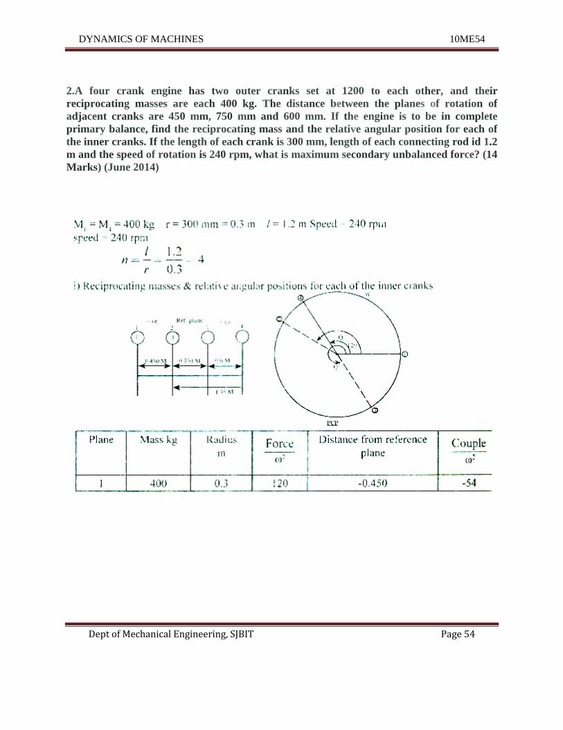
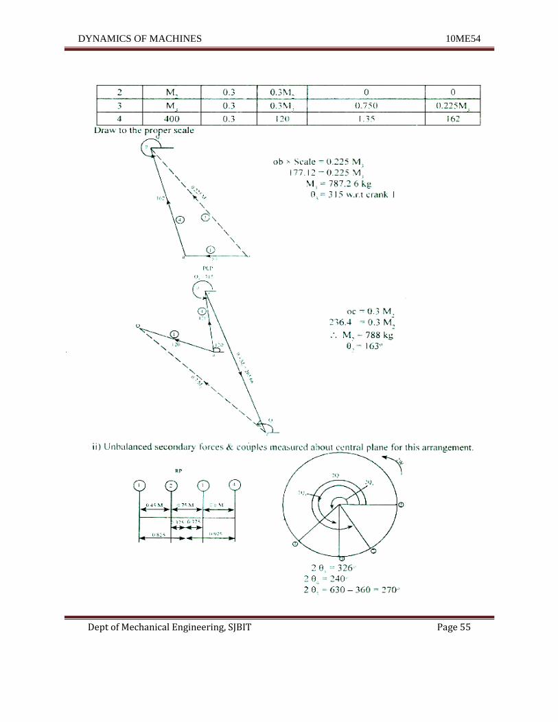
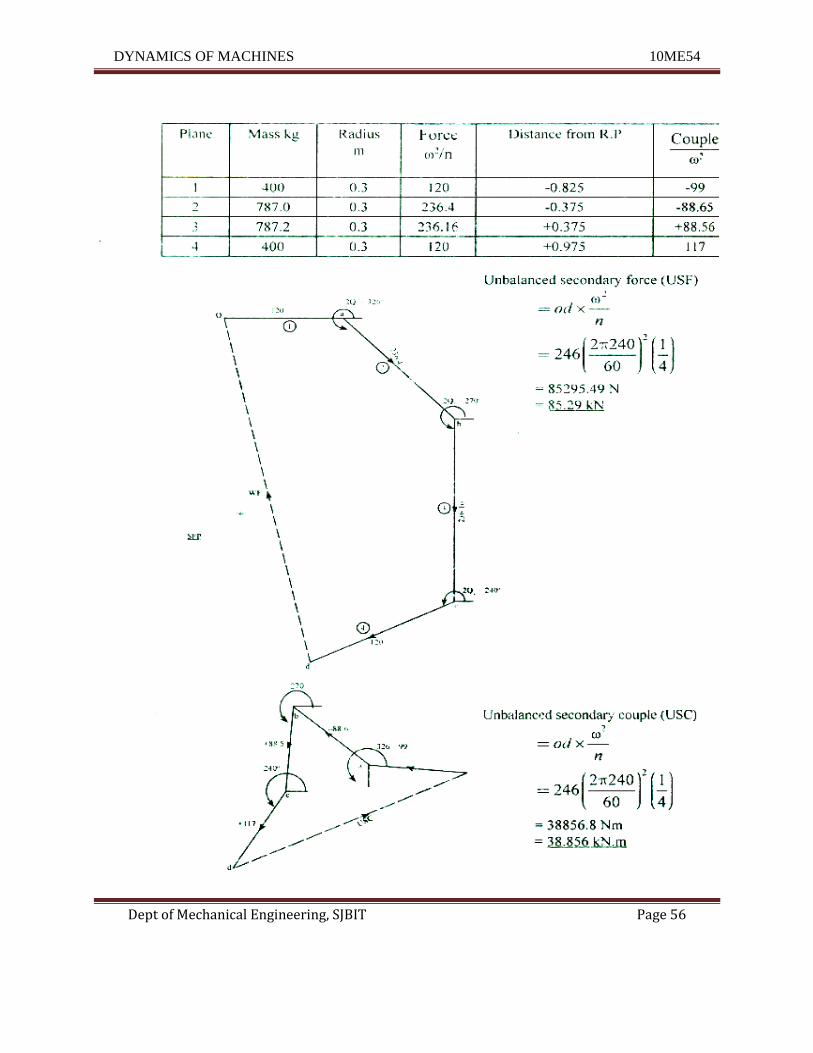
2.A four crank engine has two outer cranks set at 1200 to each other, and their
reciprocating masses are each 400 kg. The distance between the planes of rotation of
adjacent cranks are 450 mm, 750 mm and 600 mm. If the engine is to be in complete
primary balance, find the reciprocating mass and the relative angular position for each of
the inner cranks. If the length of each crank is 300 mm, length of each connecting rod id 1.2
m and the speed of rotation is 240 rpm, what is maximum secondary unbalanced force? (14
Marks) (June 2014)
DYNAMICS OF MACHINES 10ME54
Dept of Mechanical Engineering, SJBIT Page 55
DYNAMICS OF MACHINES 10ME54
Dept of Mechanical Engineering, SJBIT Page 56
DYNAMICS OF MACHINES 10ME54
Dept of Mechanical Engineering, SJBIT Page 57
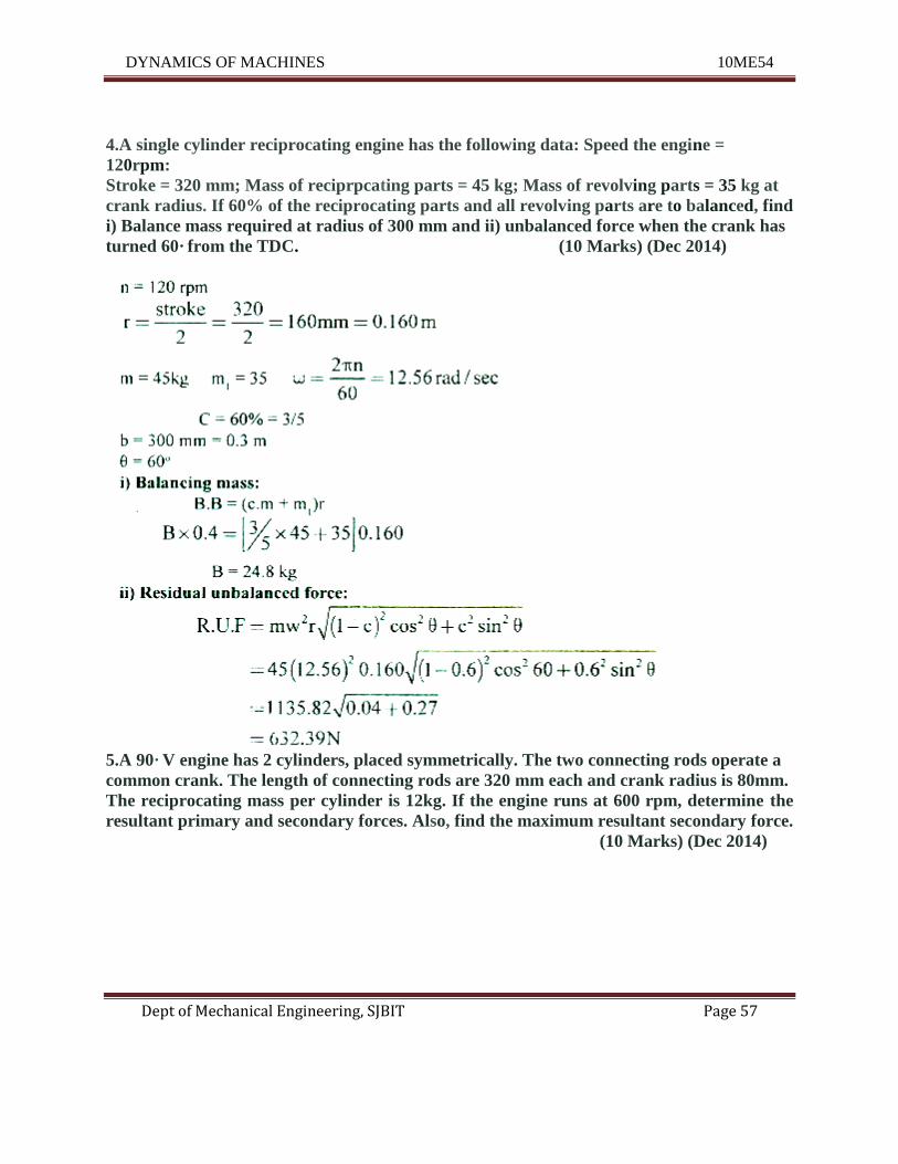
4.A single cylinder reciprocating engine has the following data: Speed the engine =
120rpm:
Stroke = 320 mm; Mass of reciprpcating parts = 45 kg; Mass of revolving parts = 35 kg at
crank radius. If 60% of the reciprocating parts and all revolving parts are to balanced, find
i) Balance mass required at radius of 300 mm and ii) unbalanced force when the crank has
turned 60· from the TDC. (10 Marks) (Dec 2014)
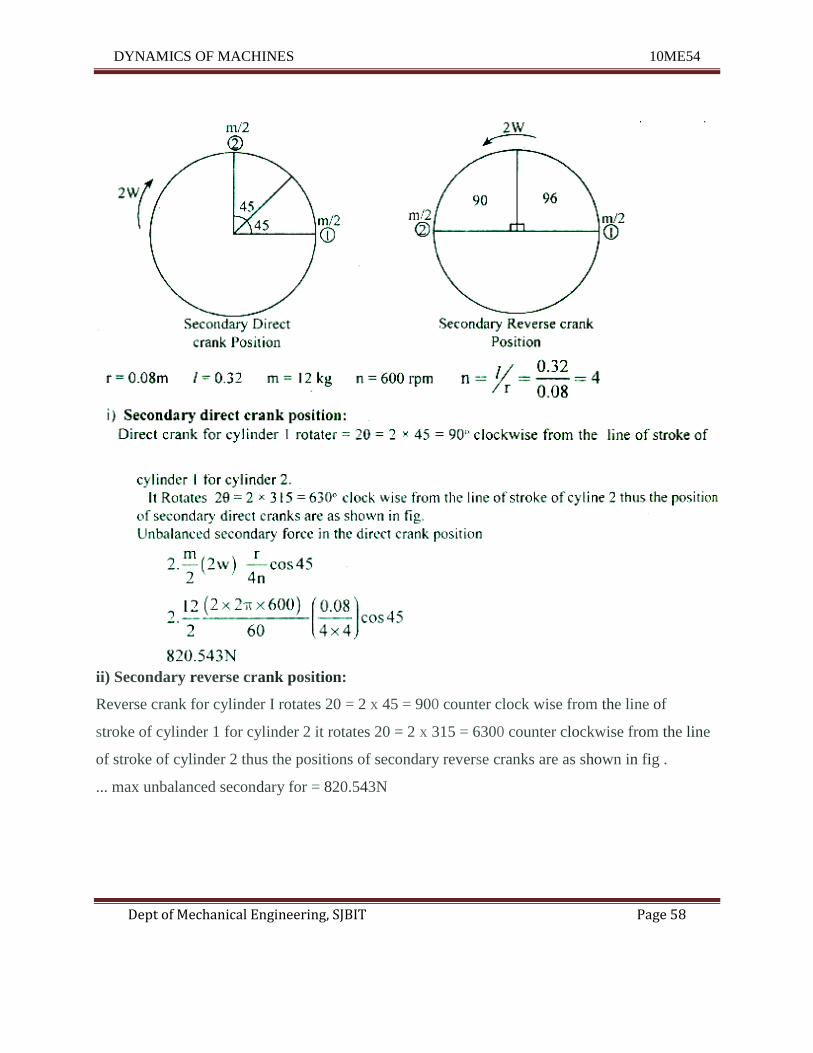
5.A 90· V engine has 2 cylinders, placed symmetrically. The two connecting rods operate a
common crank. The length of connecting rods are 320 mm each and crank radius is 80mm.
The reciprocating mass per cylinder is 12kg. If the engine runs at 600 rpm, determine the
resultant primary and secondary forces. Also, find the maximum resultant secondary force.
(10 Marks) (Dec 2014)
DYNAMICS OF MACHINES 10ME54
Dept of Mechanical Engineering, SJBIT Page 58
ii) Secondary reverse crank position:
Reverse crank for cylinder I rotates 20 = 2 x 45 = 900 counter clock wise from the line of
stroke of cylinder 1 for cylinder 2 it rotates 20 = 2 x 315 = 6300 counter clockwise from the line
of stroke of cylinder 2 thus the positions of secondary reverse cranks are as shown in fig .
... max unbalanced secondary for = 820.543N
DYNAMICS OF MACHINES 10ME54
Dept of Mechanical Engineering, SJBIT Page 59
6.Check the condition of primary and secondary balancing of 2 - cylinder and 3 - Cylinder
in line engine. (06 Marks) (June 2015)
A multi - cylinder engine with the cylinder centre 'lines in the same plane and on the centre line
of the crank shaft are known as In - line engines.
The following two conditions must be satisfied in order to give complete primary balance of
an engine.
1. The algebraic sum of the primary forces = O.
In other words the primary force polygon must close.
2. The algebraic sum of the couples about any point in the plane of the primary forces equal
to zero.
The algebraic sum of the couples about any point in the plane must be equal to zero.
In other words th! secondary couple polygon must close.
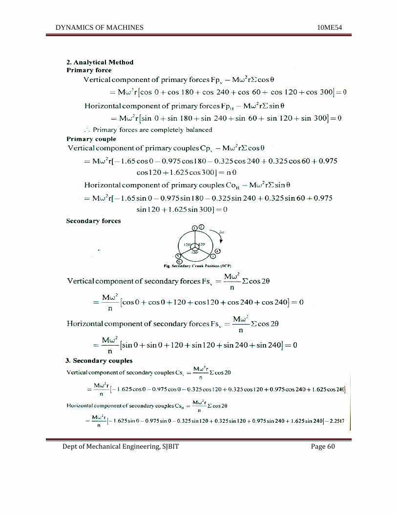
7.In an in line six cYlir der engine working on two stroke cycle, the cylinder centre lines are
spaced at 650 mm. In the end view, the cranks are 60° apart and. in the order 1-4-5-2-3-6.
The stroke of each piston is 400mm and the connecting rod length is 1m. The rotating part
is 100 Kg per crank and reciprocating mass is 250 kg/cylinder and operating speed is 240
rpm. Examine the engine for the balance for primary and secondary forces and couples.
(14 marks) (June 2015)
DYNAMICS OF MACHINES 10ME54
Dept of Mechanical Engineering, SJBIT Page 60
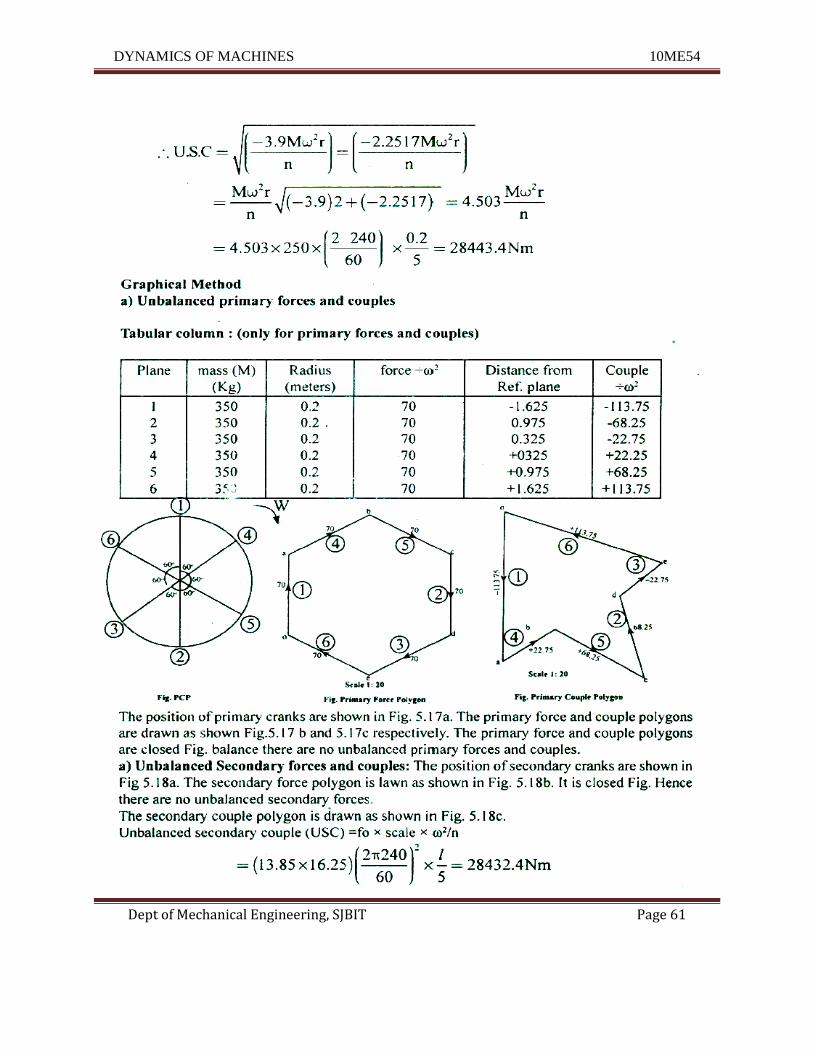
DYNAMICS OF MACHINES 10ME54
Dept of Mechanical Engineering, SJBIT Page 61
DYNAMICS OF MACHINES 10ME54
Dept of Mechanical Engineering, SJBIT Page 62
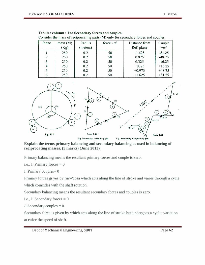
Explain the terms primary balancing and secondary balancing as used in balancing of
reciprocating masses. (5 marks) (June 2013)
Primary balancing means the resultant primary forces and couple is zero.
i.e., I: Primary forces = 0
I: Primary couples= 0
Primary forces gi yes by rnrw'cosa which acts along the line of stroke and varies through a cycle
which coincides with the shaft rotation.
Secondary balancing means the resultant secondary forces and couples is zero.
i.e., I: Secondary forces = 0
L Secondary couples = 0
Secondary force is given by which acts along the line of stroke but undergoes a cyclic variation
at twice the speed of shaft.
DYNAMICS OF MACHINES 10ME54
Dept of Mechanical Engineering, SJBIT Page 63
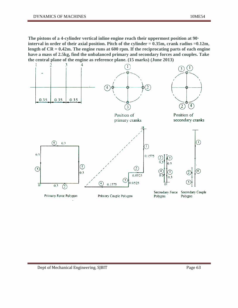
The pistons of a 4-cylinder vertical inline engine reach their uppermost position at 90·
interval in order of their axial position. Pitch of the cylinder = 0.35m, crank radius =0.12m,
length of CR = 0.42m. The engine runs at 600 rpm. If the reciprocating parts of each engine
have a mass of 2.5kg, find the unbalanced primary and secondary forces and couples. Take
the central plane of the engine as reference plane. (15 marks) (June 2013)
DYNAMICS OF MACHINES 10ME54
Dept of Mechanical Engineering, SJBIT Page 64
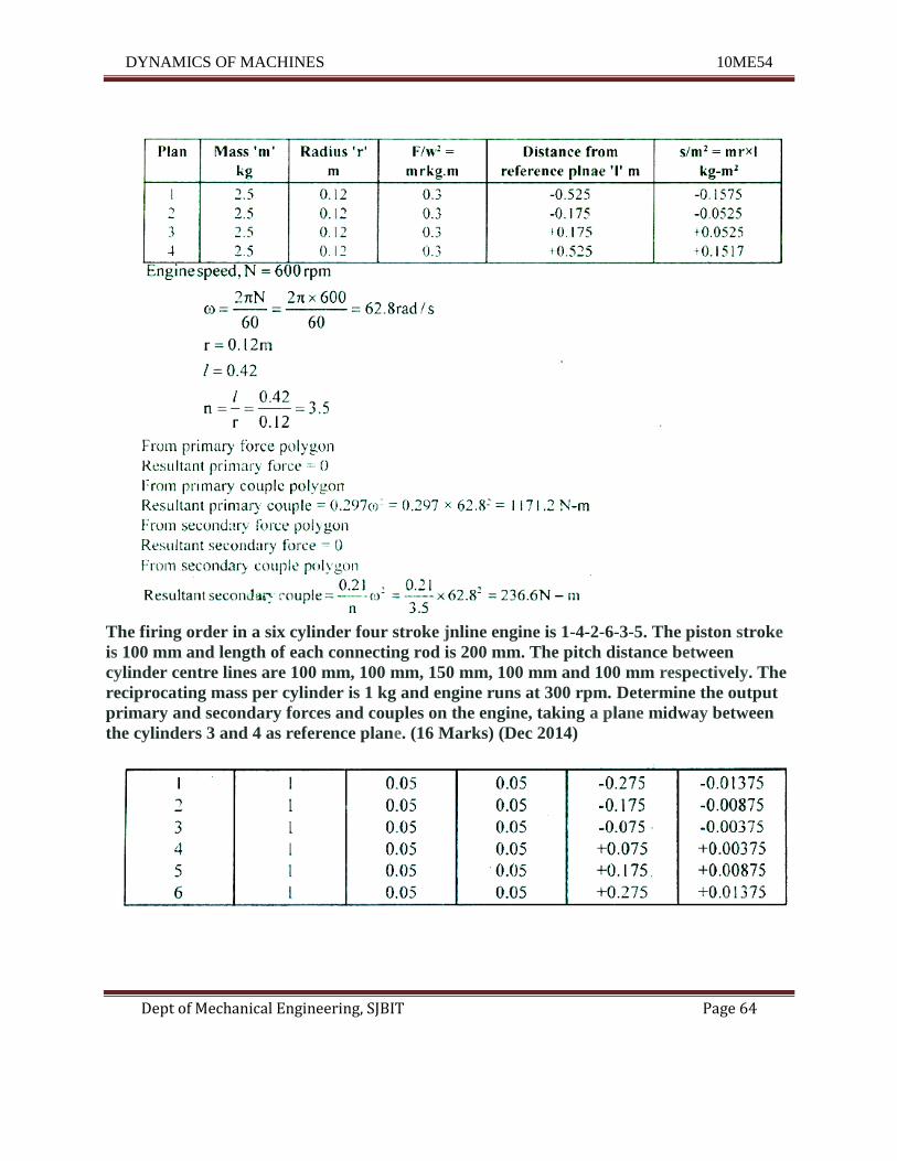
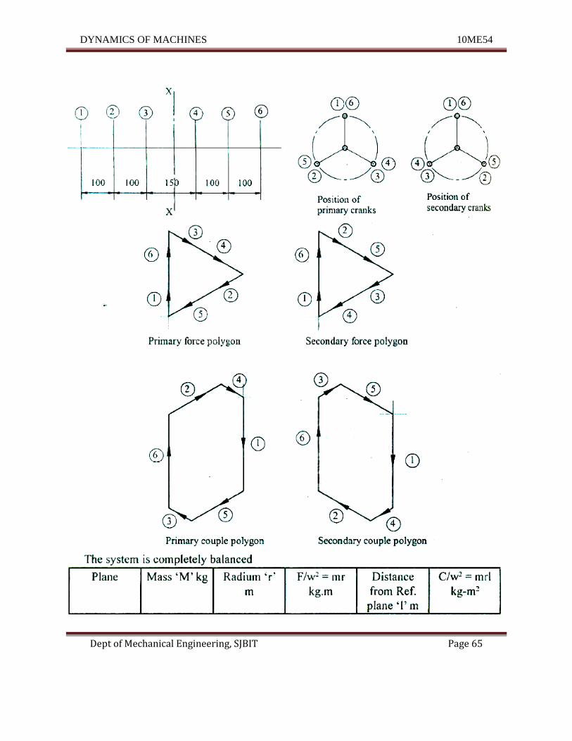
The firing order in a six cylinder four stroke jnline engine is 1-4-2-6-3-5. The piston stroke
is 100 mm and length of each connecting rod is 200 mm. The pitch distance between
cylinder centre lines are 100 mm, 100 mm, 150 mm, 100 mm and 100 mm respectively. The
reciprocating mass per cylinder is 1 kg and engine runs at 300 rpm. Determine the output
primary and secondary forces and couples on the engine, taking a plane midway between
the cylinders 3 and 4 as reference plane. (16 Marks) (Dec 2014)
DYNAMICS OF MACHINES 10ME54
Dept of Mechanical Engineering, SJBIT Page 65
DYNAMICS OF MACHINES 10ME54
Dept of Mechanical Engineering, SJBIT Page 66
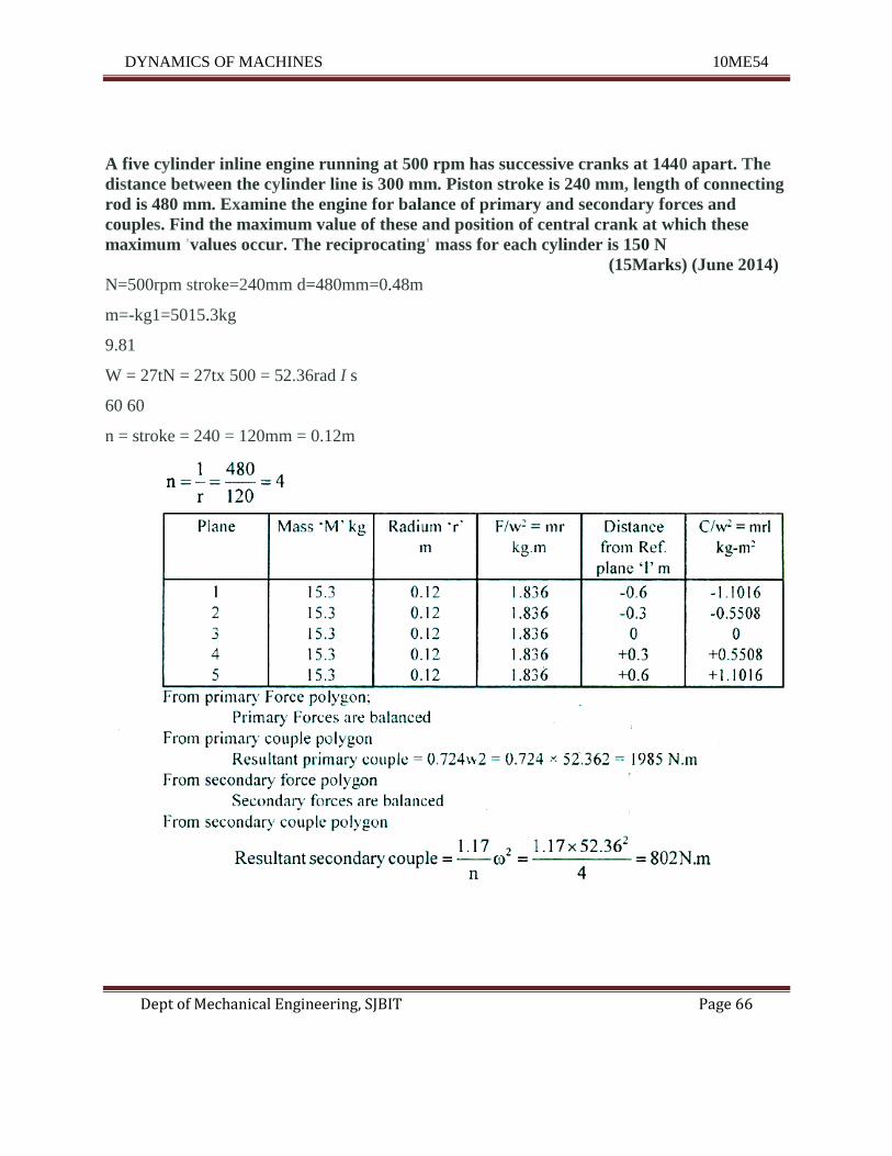
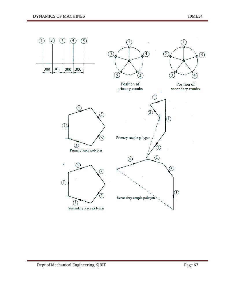
A five cylinder inline engine running at 500 rpm has successive cranks at 1440 apart. The
distance between the cylinder line is 300 mm. Piston stroke is 240 mm, length of connecting
rod is 480 mm. Examine the engine for balance of primary and secondary forces and
couples. Find the maximum value of these and position of central crank at which these
maximum 'values occur. The reciprocating' mass for each cylinder is 150 N
(15Marks) (June 2014)
N=500rpm stroke=240mm d=480mm=0.48m
m=-kg1=5015.3kg
9.81
W = 27tN = 27tx 500 = 52.36rad I s
60 60
n = stroke = 240 = 120mm = 0.12m
DYNAMICS OF MACHINES 10ME54
Dept of Mechanical Engineering, SJBIT Page 67
DYNAMICS OF MACHINES 10ME54
Dept of Mechanical Engineering, SJBIT Page 68
UNIT – 6
Governors
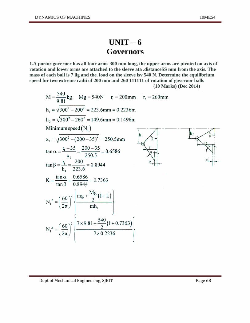
1.A portor governer has all four arms 300 mm long, the upper arms are pivoted on axis of
rotation and lower arms are attached to the sleeve ata .distanceSS mm from the axis. The
mass of each ball is 7 lig and the. load on the sleeve isv 540 N. Determine the equilibrium
speed for two extreme radii of 200 mm and 260 111111 of rotation of governor balls
(10 Marks) (Dec 2014)
DYNAMICS OF MACHINES 10ME54
Dept of Mechanical Engineering, SJBIT Page 69
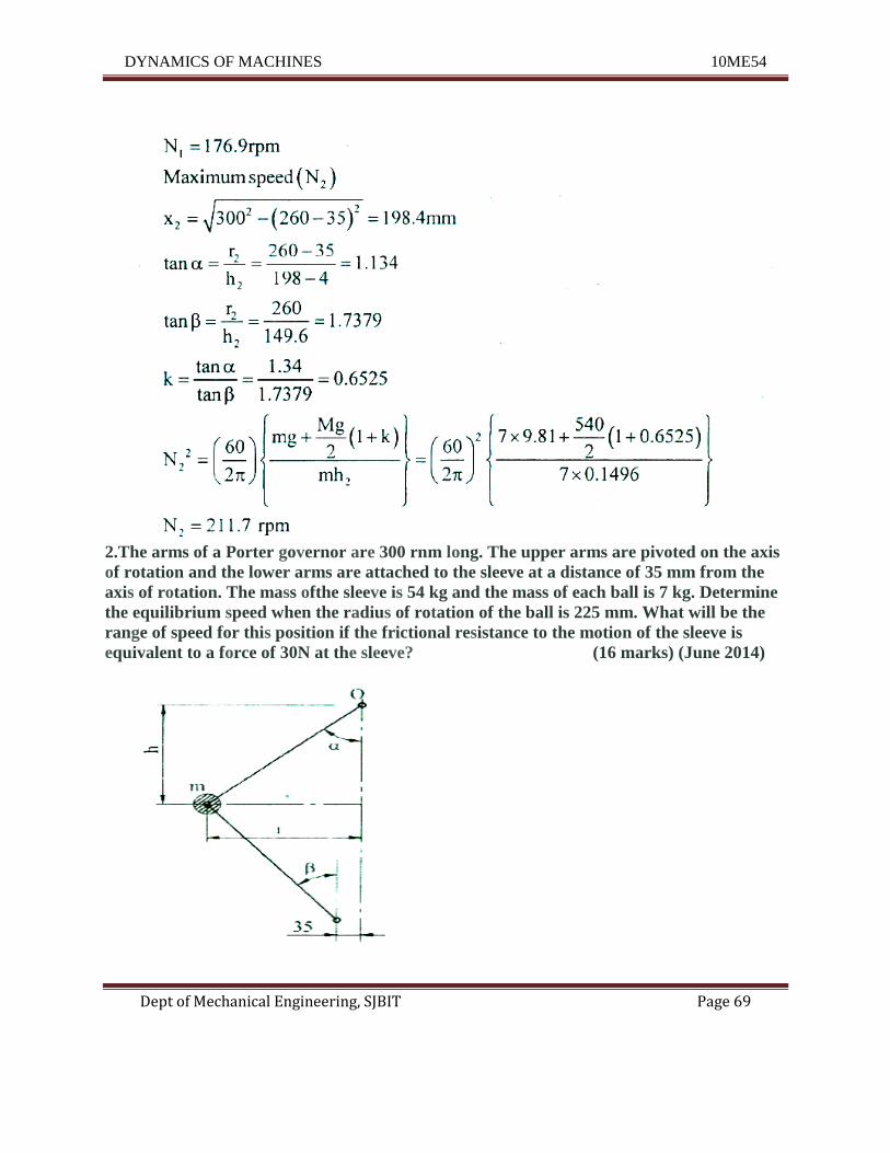
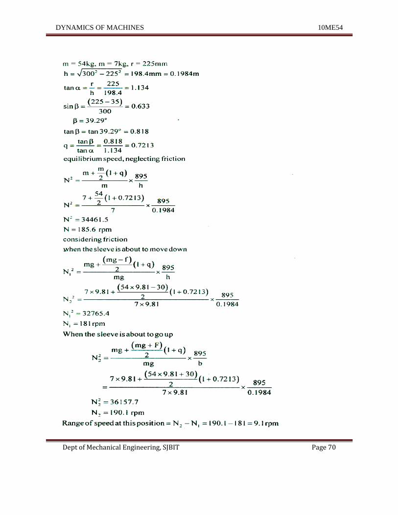
2.The arms of a Porter governor are 300 rnm long. The upper arms are pivoted on the axis
of rotation and the lower arms are attached to the sleeve at a distance of 35 mm from the
axis of rotation. The mass ofthe sleeve is 54 kg and the mass of each ball is 7 kg. Determine
the equilibrium speed when the radius of rotation of the ball is 225 mm. What will be the
range of speed for this position if the frictional resistance to the motion of the sleeve is
equivalent to a force of 30N at the sleeve? (16 marks) (June 2014)
DYNAMICS OF MACHINES 10ME54
Dept of Mechanical Engineering, SJBIT Page 70
DYNAMICS OF MACHINES 10ME54
Dept of Mechanical Engineering, SJBIT Page 71
3.Explain sensitiveness, isochronism, effect and power of a governor. (8 marks) (June 2013)
i) Sensitiveness : It is the ration of the difference between the maximum
equilibrium speed to the mean equilibrium speed.
IfN2 = Maximum equilibrium speed.
N I = Minimum Equilibrium speed.
N = Mean equilibrium speed.
ii) Governor effort: It is the mean force exerted on the sleeve to raise it or lower it for given
percentage change of speed.
iii) Governor power: It is the work done on the sleeve for a given percentage change speed. So
the Governor power us nothing but the product of mean effort and the distance through which
the sleeve moves. •
.'. Governor Power = Mean effort x Loft of the sleeve
iv) Isochronous Governor: A Governor is said to be isochronous if the equilibrium speed is
constant for all radii of rotation of the balls with in the working range.
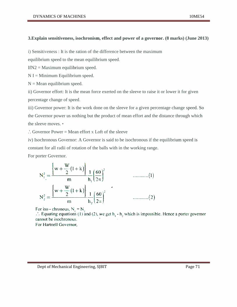
For porter Governor.
DYNAMICS OF MACHINES 10ME54
Dept of Mechanical Engineering, SJBIT Page 72
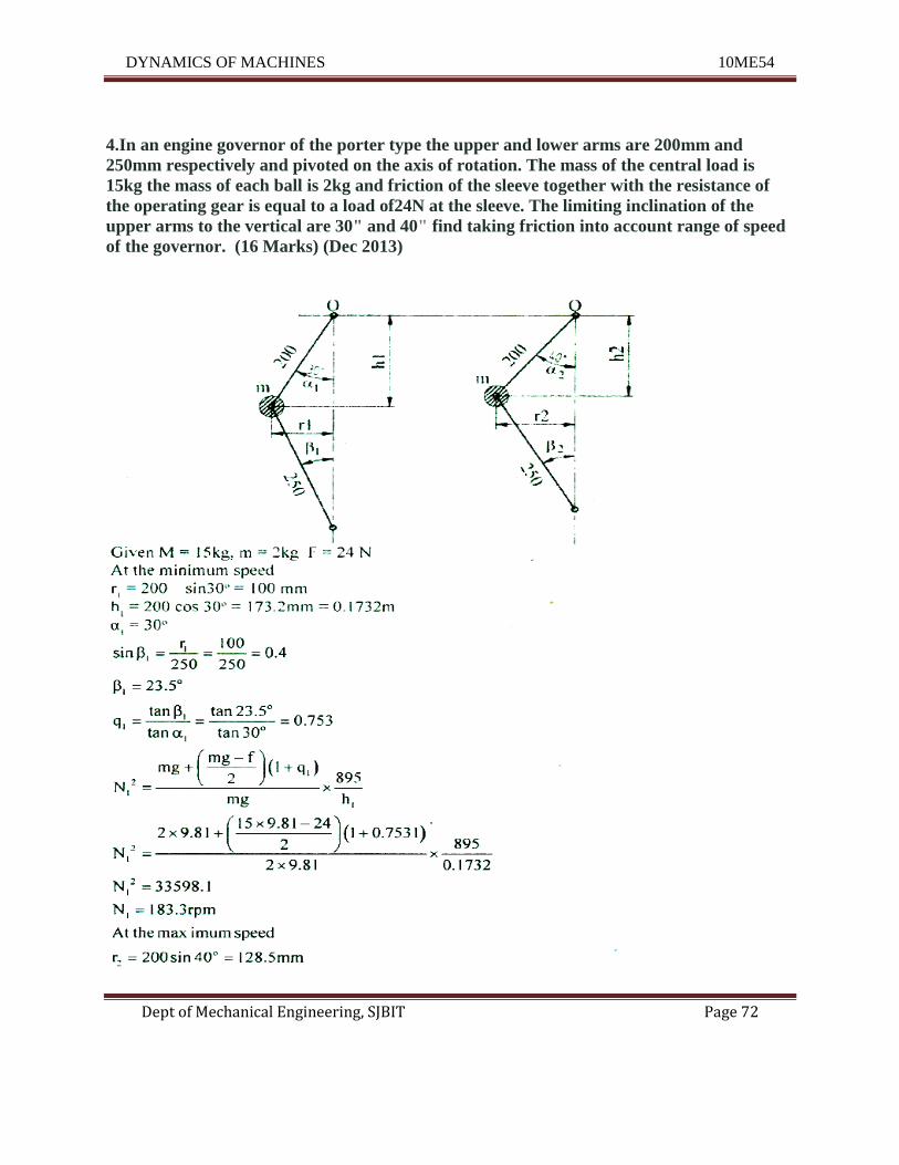
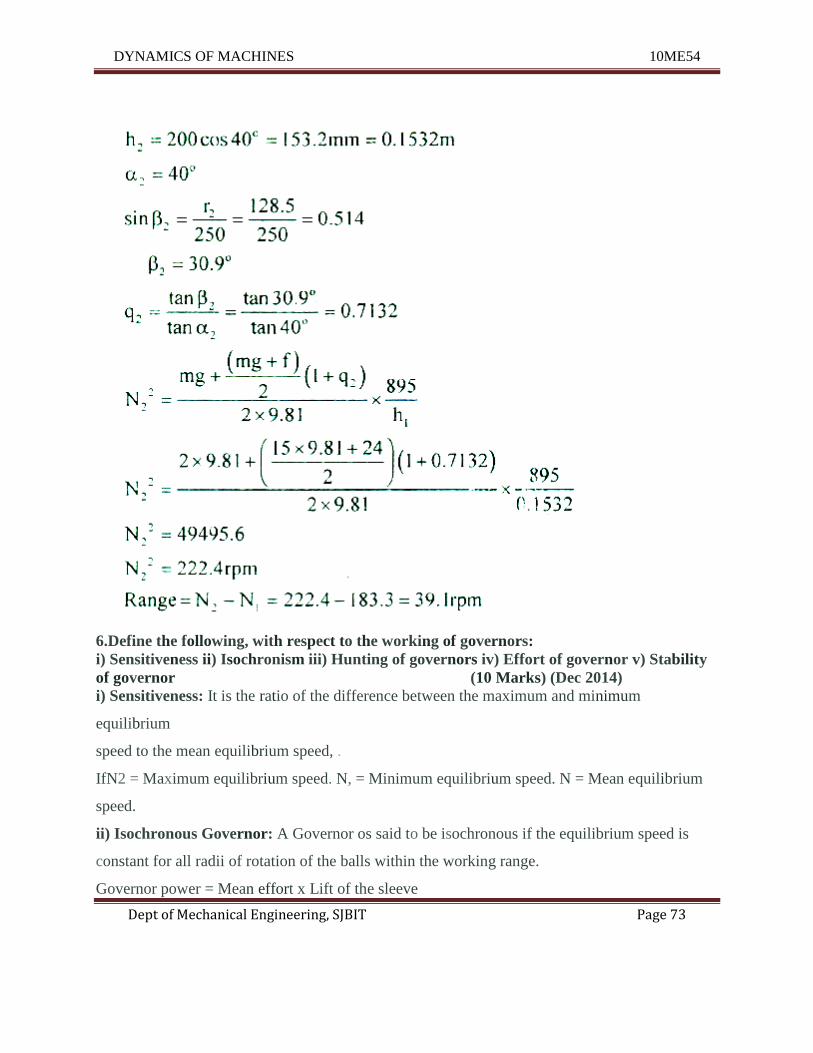
4.In an engine governor of the porter type the upper and lower arms are 200mm and
250mm respectively and pivoted on the axis of rotation. The mass of the central load is
15kg the mass of each ball is 2kg and friction of the sleeve together with the resistance of
the operating gear is equal to a load of24N at the sleeve. The limiting inclination of the
upper arms to the vertical are 30" and 40" find taking friction into account range of speed
of the governor. (16 Marks) (Dec 2013)
DYNAMICS OF MACHINES 10ME54
Dept of Mechanical Engineering, SJBIT Page 73
6.Define the following, with respect to the working of governors:
i) Sensitiveness ii) Isochronism iii) Hunting of governors iv) Effort of governor v) Stability
of governor (10 Marks) (Dec 2014)
i) Sensitiveness: It is the ratio of the difference between the maximum and minimum
equilibrium
speed to the mean equilibrium speed, .
IfN2 = Maximum equilibrium speed. N, = Minimum equilibrium speed. N = Mean equilibrium
speed.
ii) Isochronous Governor: A Governor os said to be isochronous if the equilibrium speed is
constant for all radii of rotation of the balls within the working range.
Governor power = Mean effort x Lift of the sleeve
DYNAMICS OF MACHINES 10ME54
Dept of Mechanical Engineering, SJBIT Page 74
iii) Hunting: If the speed of the engine controlled by the governor fluctuates continuously above
and below the mean speed, then the condition is said to be hinting. This is caused by too
sensitive governor. In actual practice hunting is impossible in an isochronous governor because
of the friction of the mechanism. Normally in an unstable governor hunting will occur and that
too to a great extent.
iv) Governor effort: It is the mean force exerted on the sleeve to raise it or lower it for a given
percentage change of speed.
v) Stability: A governor is said to be stable when for each speed within the working range, the
ball weights occupy a definite specified position. In other words, there is only one radius of
rotation of the governor balls for each equilibrium speed, i.e., For stable governor if the
equilibrium speed increases the radius of rotation of balls must also increase.
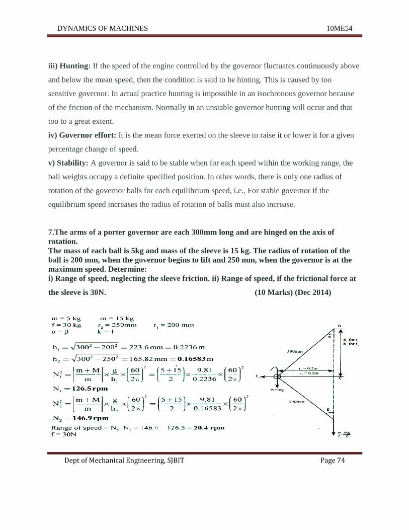
7.The arms of a porter governor are each 300mm long and are hinged on the axis of
rotation.
The mass of each ball is 5kg and mass of the sleeve is 15 kg. The radius of rotation of the
ball is 200 mm, when the governor begins to lift and 250 mm, when the governor is at the
maximum speed. Determine:
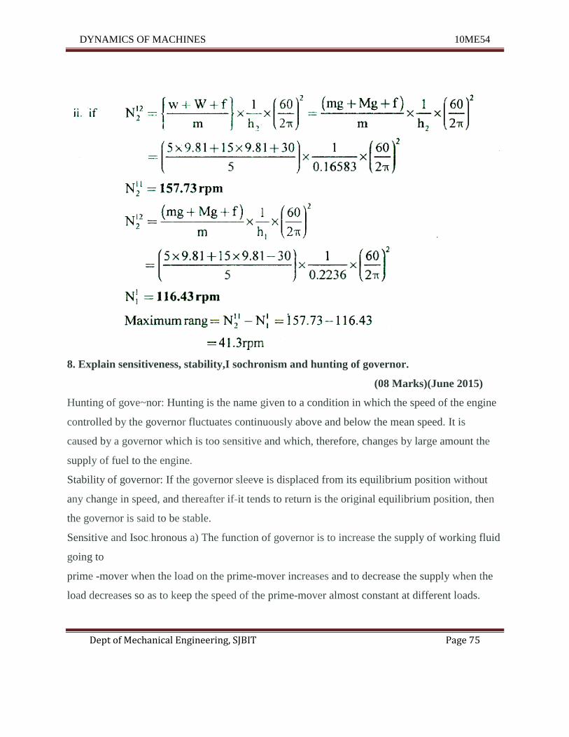
i) Range of speed, neglecting the sleeve friction. ii) Range of speed, if the frictional force at
the sleeve is 30N. (10 Marks) (Dec 2014)
DYNAMICS OF MACHINES 10ME54
Dept of Mechanical Engineering, SJBIT Page 75
8. Explain sensitiveness, stability,I sochronism and hunting of governor.
(08 Marks)(June 2015)
Hunting of gove~nor: Hunting is the name given to a condition in which the speed of the engine
controlled by the governor fluctuates continuously above and below the mean speed. It is
caused by a governor which is too sensitive and which, therefore, changes by large amount the
supply of fuel to the engine.
Stability of governor: If the governor sleeve is displaced from its equilibrium position without
any change in speed, and thereafter if-it tends to return is the original equilibrium position, then
the governor is said to be stable.
Sensitive and Isoc.hronous a) The function of governor is to increase the supply of working fluid
going to
prime -mover when the load on the prime-mover increases and to decrease the supply when the
load decreases so as to keep the speed of the prime-mover almost constant at different loads.
DYNAMICS OF MACHINES 10ME54
Dept of Mechanical Engineering, SJBIT Page 76
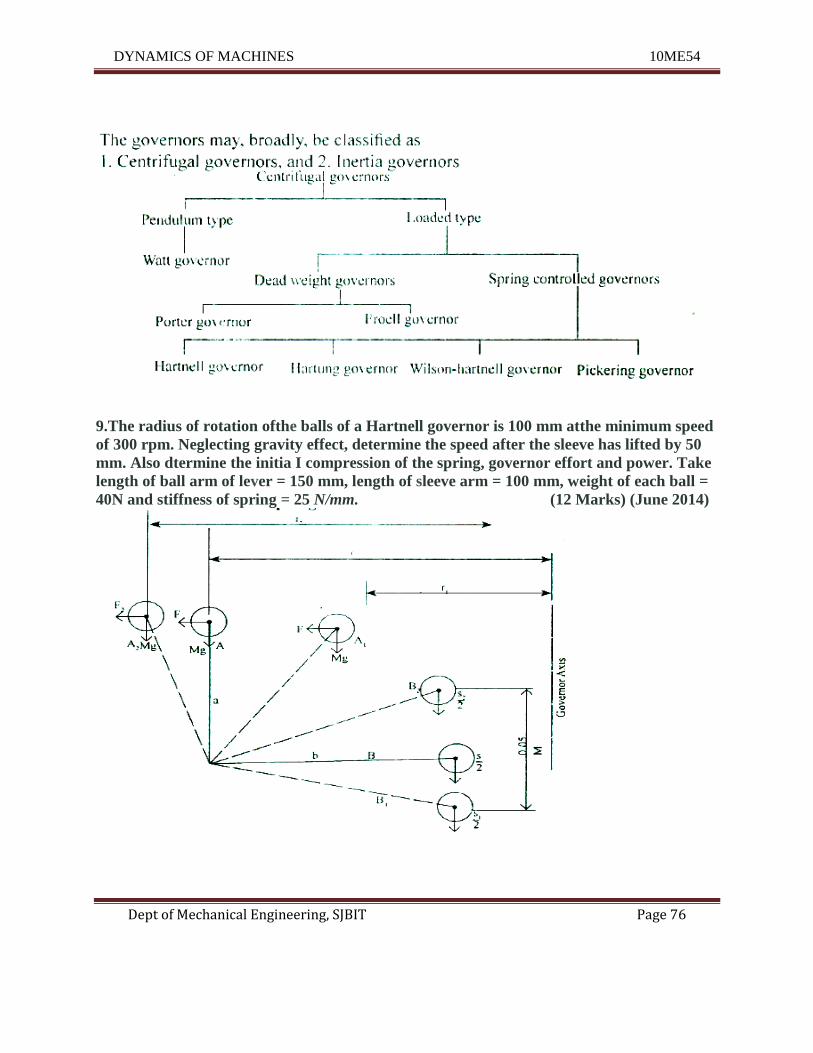
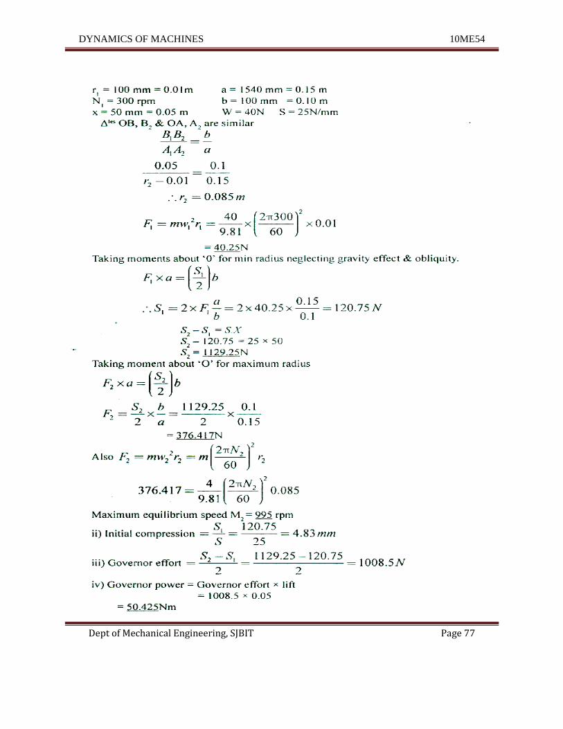
9.The radius of rotation ofthe balls of a Hartnell governor is 100 mm atthe minimum speed
of 300 rpm. Neglecting gravity effect, determine the speed after the sleeve has lifted by 50
mm. Also dtermine the initia I compression of the spring, governor effort and power. Take
length of ball arm of lever = 150 mm, length of sleeve arm = 100 mm, weight of each ball =
40N and stiffness of spring = 25 N/mm. (12 Marks) (June 2014)
DYNAMICS OF MACHINES 10ME54
Dept of Mechanical Engineering, SJBIT Page 77
DYNAMICS OF MACHINES 10ME54
Dept of Mechanical Engineering, SJBIT Page 78
UNIT – 7
Gyroscope
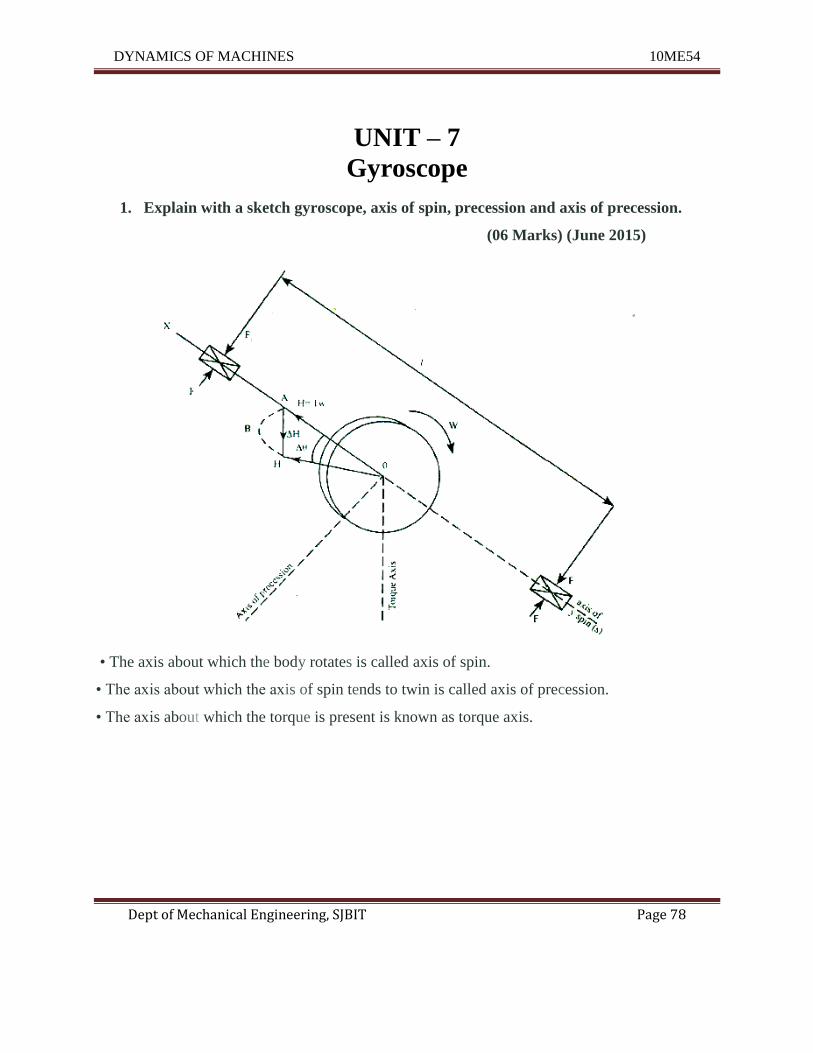
1. Explain with a sketch gyroscope, axis of spin, precession and axis of precession.
(06 Marks) (June 2015)
• The axis about which the body rotates is called axis of spin.
• The axis about which the axis of spin tends to twin is called axis of precession.
• The axis about which the torque is present is known as torque axis.
DYNAMICS OF MACHINES 10ME54
Dept of Mechanical Engineering, SJBIT Page 79
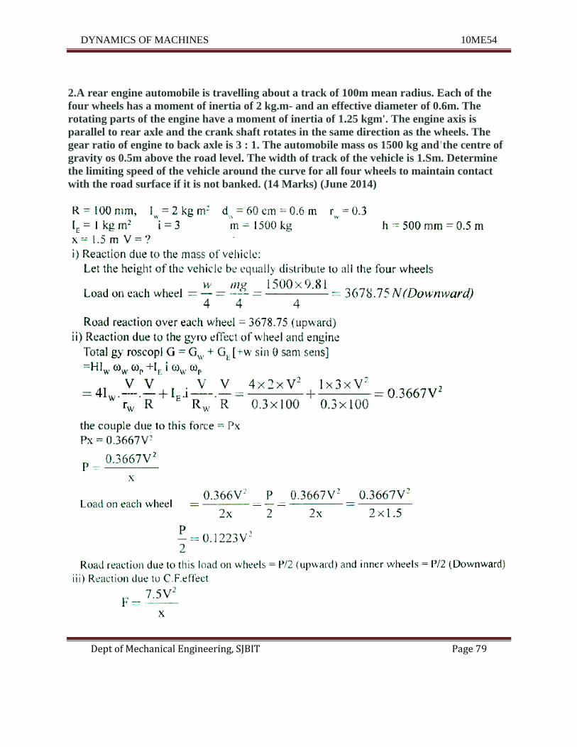
2.A rear engine automobile is travelling about a track of 100m mean radius. Each of the
four wheels has a moment of inertia of 2 kg.m- and an effective diameter of 0.6m. The
rotating parts of the engine have a moment of inertia of 1.25 kgm'. The engine axis is
parallel to rear axle and the crank shaft rotates in the same direction as the wheels. The
gear ratio of engine to back axle is 3 : 1. The automobile mass os 1500 kg and'the centre of
gravity os 0.5m above the road level. The width of track of the vehicle is 1.Sm. Determine
the limiting speed of the vehicle around the curve for all four wheels to maintain contact
with the road surface if it is not banked. (14 Marks) (June 2014)
DYNAMICS OF MACHINES 10ME54
Dept of Mechanical Engineering, SJBIT Page 80
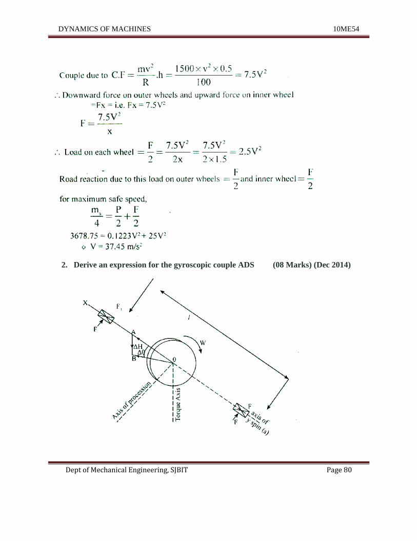
2. Derive an expression for the gyroscopic couple ADS (08 Marks) (Dec 2014)
DYNAMICS OF MACHINES 10ME54
Dept of Mechanical Engineering, SJBIT Page 81
Consider as disc keyed to or shaft which is rotating in bearing X & Y as shown in fig.
Axes S.P &T are mutually perpendicular to each other. Angular moment is Iw and by right hand
rule the angular momentum vector H is directed as shown in fig.
If the shaft is tilted or displaced through an angles tl9 about the axis 'P' the angular momentum
changes from Hto HI then tlH is change in angular moment to determine tlH draw on arc with '0'
is centre & OA as radius.
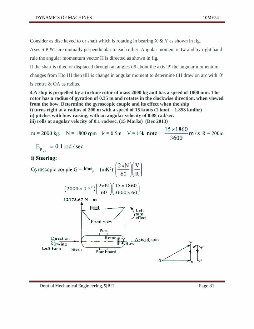
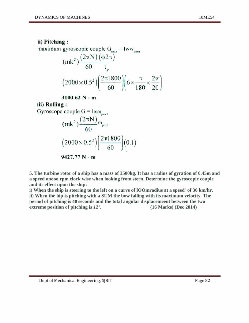
4.A ship is propelled by a turbine rotor of mass 2000 kg and has a speed of 1800 mm. The
rotor has a radius of gyration of 0.35 m and rotates in the clockwise direction, when viewed
from the bow. Determine the gyroscopic couple and its effect when the ship
i) turns right at a radius of 200 m with a speed of 15 knots (1 knot = 1.853 kmlhr)
ii) pitches with bow raising, with an angular velocity of 0.08 rad/sec.
iii) rolls at angular velocity of 0.1 rad/sec. (15 Marks) (Dec 2013)
DYNAMICS OF MACHINES 10ME54
Dept of Mechanical Engineering, SJBIT Page 82
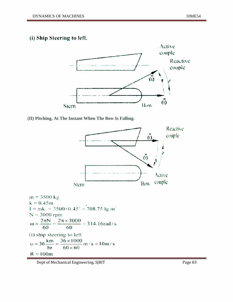
5. The turbine rotor of a ship has a mass of 3500kg. It has a radius of gyration of 0.45m and
a speed onooo rpm clock wise when looking from stern. Determine the gyroscopic couple
and its effect upon the ship:
i) When the ship is steering to the left on a curve of lOOmradius at a speed' of 36 km/hr.
li) When the hip is pitching with a SUM the bow falling with its maximum velocity. The
period of pitching is 40 seconds and the total angular displacemeent between the two
extreme position of pitching is 12°. (16 Marks) (Dec 2014)
DYNAMICS OF MACHINES 10ME54
Dept of Mechanical Engineering, SJBIT Page 83
(II) Pitching, At The Instant When The Bow Is Falling.
DYNAMICS OF MACHINES 10ME54
Dept of Mechanical Engineering, SJBIT Page 84
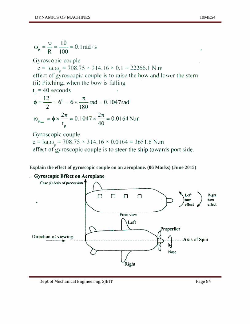
Explain the effect of gyroscopic couple on an aeroplane. (06 Marks) (June 2015)
DYNAMICS OF MACHINES 10ME54
Dept of Mechanical Engineering, SJBIT Page 85
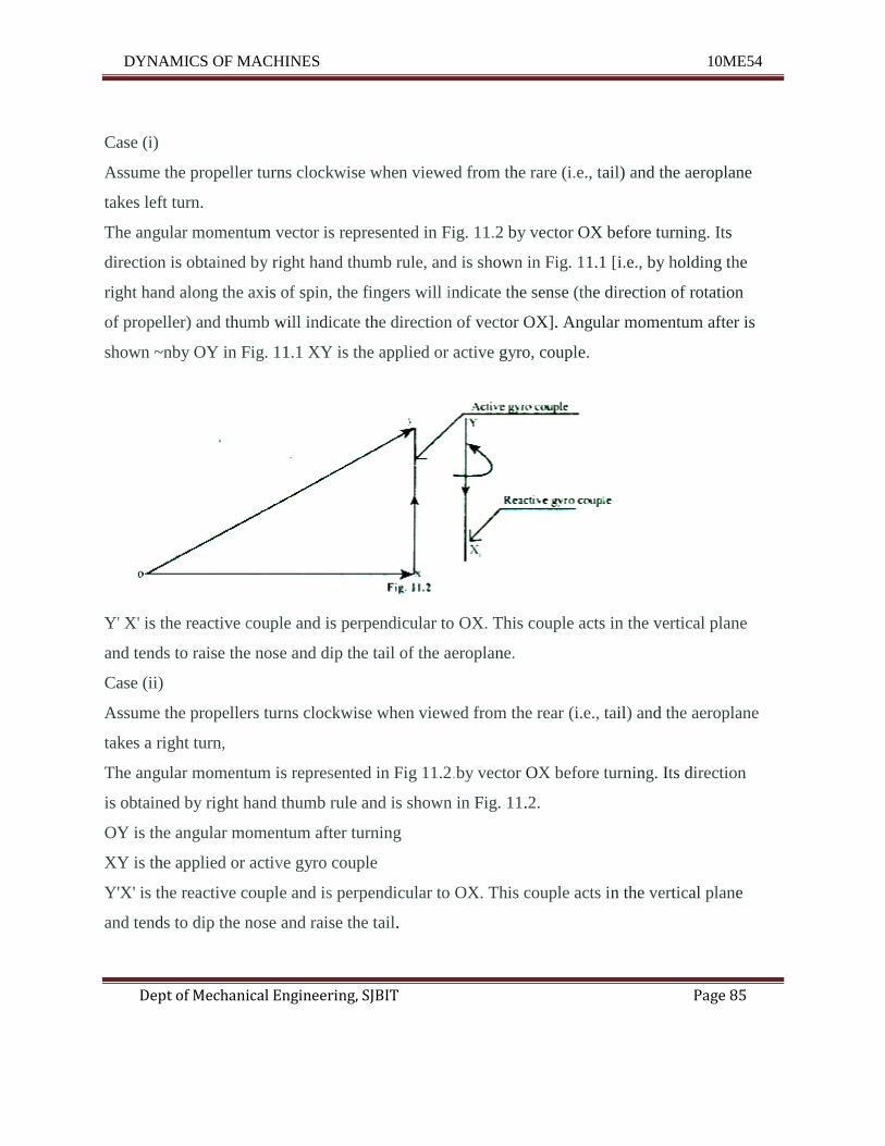
Case (i)
Assume the propeller turns clockwise when viewed from the rare (i.e., tail) and the aeroplane
takes left turn.
The angular momentum vector is represented in Fig. 11.2 by vector OX before turning. Its
direction is obtained by right hand thumb rule, and is shown in Fig. 11.1 [i.e., by holding the
right hand along the axis of spin, the fingers will indicate the sense (the direction of rotation
of propeller) and thumb will indicate the direction of vector OX]. Angular momentum after is
shown ~nby OY in Fig. 11.1 XY is the applied or active gyro, couple.
Y' X' is the reactive couple and is perpendicular to OX. This couple acts in the vertical plane
and tends to raise the nose and dip the tail of the aeroplane.
Case (ii)
Assume the propellers turns clockwise when viewed from the rear (i.e., tail) and the aeroplane
takes a right turn,
The angular momentum is represented in Fig 11.2.by vector OX before turning. Its direction
is obtained by right hand thumb rule and is shown in Fig. 11.2.
OY is the angular momentum after turning
XY is the applied or active gyro couple
Y'X' is the reactive couple and is perpendicular to OX. This couple acts in the vertical plane
and tends to dip the nose and raise the tail.
DYNAMICS OF MACHINES 10ME54
Dept of Mechanical Engineering, SJBIT Page 86
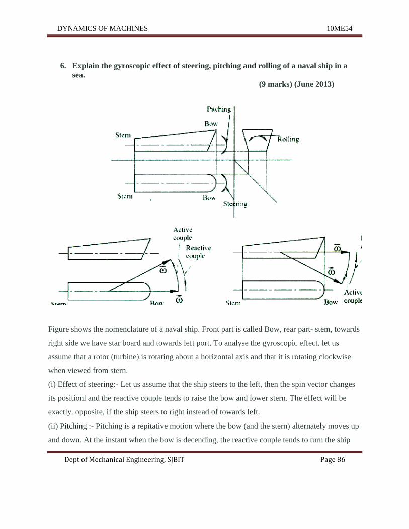
6. Explain the gyroscopic effect of steering, pitching and rolling of a naval ship in a
sea.
(9 marks) (June 2013)
Figure shows the nomenclature of a naval ship. Front part is called Bow, rear part- stem, towards
right side we have star board and towards left port. To analyse the gyroscopic effect. let us
assume that a rotor (turbine) is rotating about a horizontal axis and that it is rotating clockwise
when viewed from stern.
(i) Effect of steering:- Let us assume that the ship steers to the left, then the spin vector changes
its positionl and the reactive couple tends to raise the bow and lower stern. The effect will be
exactly. opposite, if the ship steers to right instead of towards left.
(ii) Pitching :- Pitching is a repitative motion where the bow (and the stern) alternately moves up
and down. At the instant when the bow is decending, the reactive couple tends to turn the ship
DYNAMICS OF MACHINES 10ME54
Dept of Mechanical Engineering, SJBIT Page 87
towards portside. Similarly, when the bow is ascending, the reactive couple tends to turn the
ship towards star board side.
(iii) Rolling :- In this particular case the axis of spin coincides with the axis of rolling (shown
in side view). Since there is no precession of spin axis there is no gyroscopic effect.
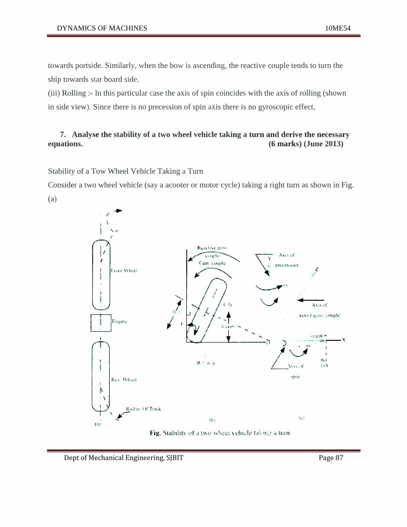
7. Analyse the stability of a two wheel vehicle taking a turn and derive the necessary
equations. (6 marks) (June 2013)
Stability of a Tow Wheel Vehicle Taking a Turn
Consider a two wheel vehicle (say a acooter or motor cycle) taking a right turn as shown in Fig.
(a)
DYNAMICS OF MACHINES 10ME54
Dept of Mechanical Engineering, SJBIT Page 88
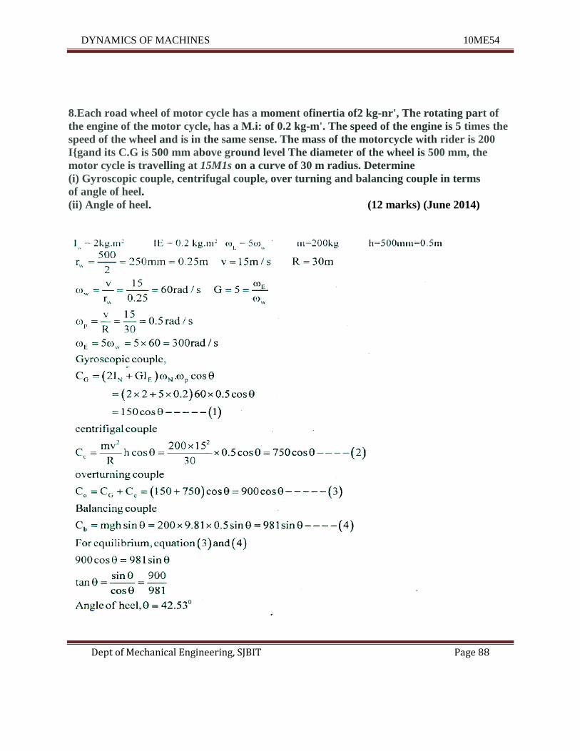
8.Each road wheel of motor cycle has a moment ofinertia of2 kg-nr', The rotating part of
the engine of the motor cycle, has a M.i: of 0.2 kg-m'. The speed of the engine is 5 times the
speed of the wheel and is in the same sense. The mass of the motorcycle with rider is 200
I{gand its C.G is 500 mm above ground level The diameter of the wheel is 500 mm, the
motor cycle is travelling at 15M1s on a curve of 30 m radius. Determine
(i) Gyroscopic couple, centrifugal couple, over turning and balancing couple in terms
of angle of heel.
(ii) Angle of heel. (12 marks) (June 2014)
DYNAMICS OF MACHINES 10ME54
Dept of Mechanical Engineering, SJBIT Page 89
UNIT – 8
Analysis of Cams
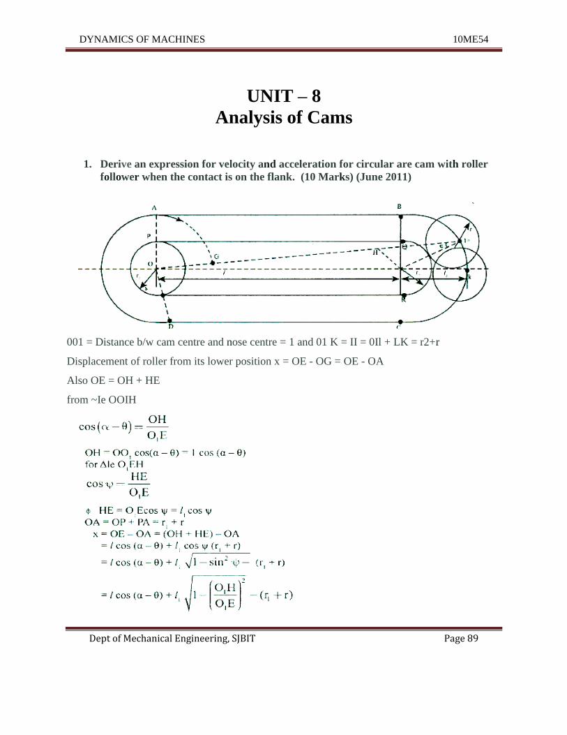
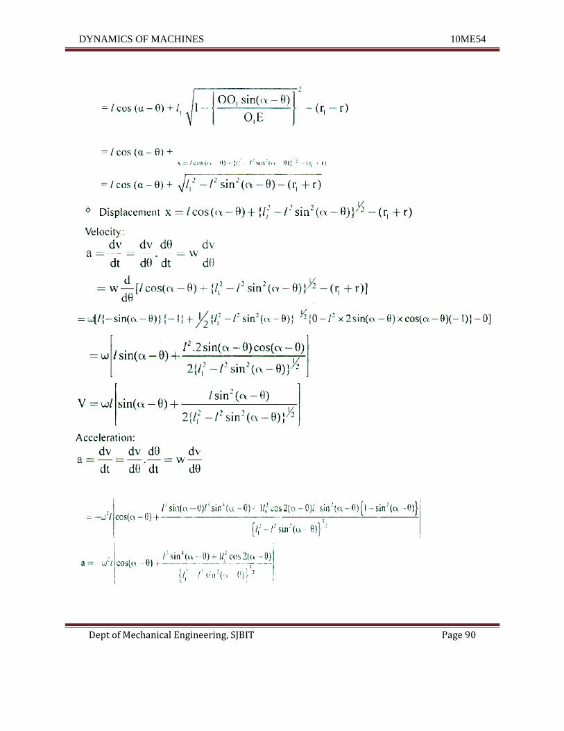
1. Derive an expression for velocity and acceleration for circular are cam with roller
follower when the contact is on the flank. (10 Marks) (June 2011)
001 = Distance b/w cam centre and nose centre = 1 and 01 K = II = 0Il + LK = r2+r
Displacement of roller from its lower position x = OE - OG = OE - OA
Also OE = OH + HE
from ~Ie OOIH
DYNAMICS OF MACHINES 10ME54
Dept of Mechanical Engineering, SJBIT Page 90
DYNAMICS OF MACHINES 10ME54
Dept of Mechanical Engineering, SJBIT Page 91
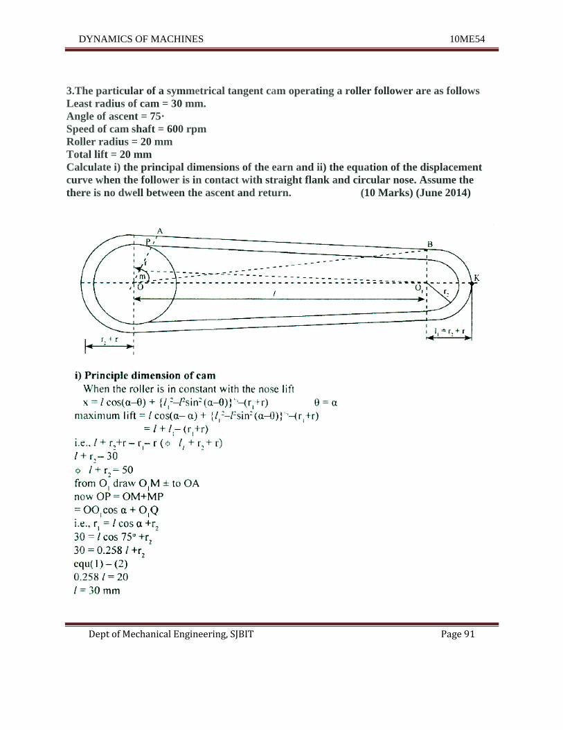
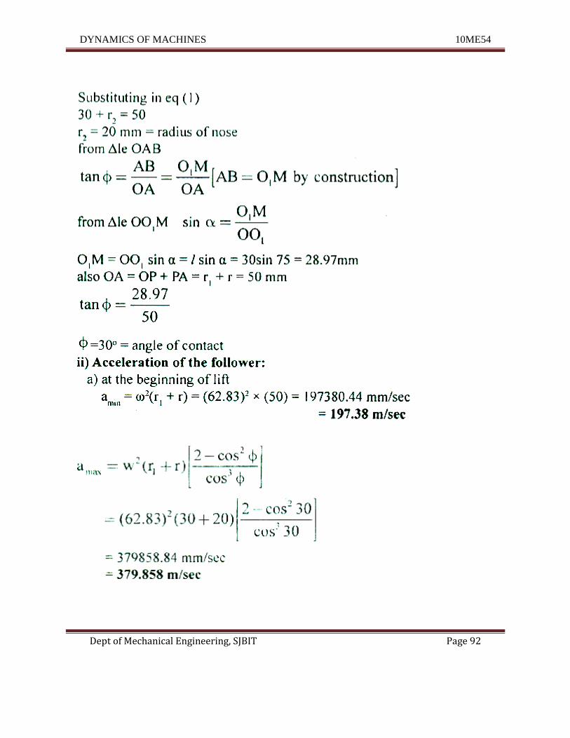
3.The particular of a symmetrical tangent cam operating a roller follower are as follows
Least radius of cam = 30 mm.
Angle of ascent = 75·
Speed of cam shaft = 600 rpm
Roller radius = 20 mm
Total lift = 20 mm
Calculate i) the principal dimensions of the earn and ii) the equation of the displacement
curve when the follower is in contact with straight flank and circular nose. Assume the
there is no dwell between the ascent and return. (10 Marks) (June 2014)
DYNAMICS OF MACHINES 10ME54
Dept of Mechanical Engineering, SJBIT Page 92
DYNAMICS OF MACHINES 10ME54
Dept of Mechanical Engineering, SJBIT Page 93
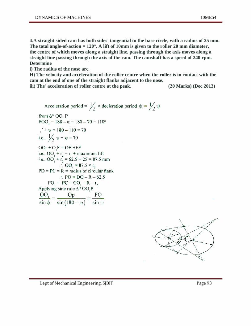
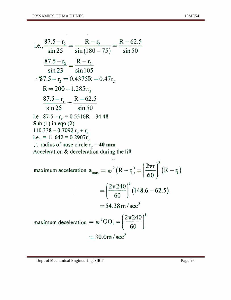
4.A straight sided cam has both sides' tangential to the base circle, with a radius of 25 mm.
The total angle-of-action = 120°. A lift of 10mm is given to the roller 20 mm diameter,
the centre of which moves along a straight line, passing through the axis moves along a
straight line passing through the axis of the cam. The camshaft has a speed of 240 rpm.
Determine
i) The radius of the nose arc.
H) The velocity and acceleration of the roller centre when the roller is in contact with the
cam at the end of one of the straight flanks adjacent to the nose.
iii) The' acceleration of roller centre at the peak. (20 Marks) (Dec 2013)
DYNAMICS OF MACHINES 10ME54
Dept of Mechanical Engineering, SJBIT Page 94
DYNAMICS OF MACHINES 10ME54
Dept of Mechanical Engineering, SJBIT Page 95
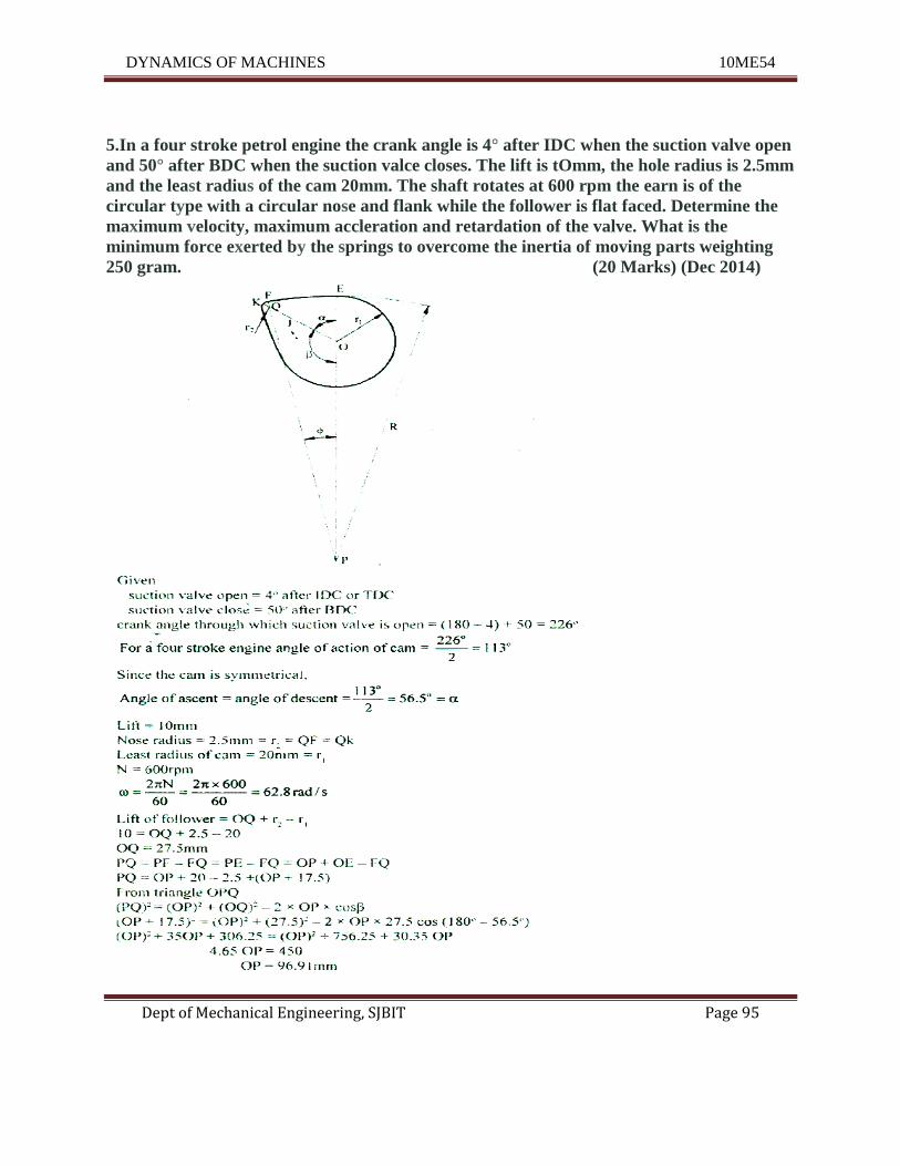
5.In a four stroke petrol engine the crank angle is 4° after IDC when the suction valve open
and 50° after BDC when the suction valce closes. The lift is tOmm, the hole radius is 2.5mm
and the least radius of the cam 20mm. The shaft rotates at 600 rpm the earn is of the
circular type with a circular nose and flank while the follower is flat faced. Determine the
maximum velocity, maximum accleration and retardation of the valve. What is the
minimum force exerted by the springs to overcome the inertia of moving parts weighting
250 gram. (20 Marks) (Dec 2014)
DYNAMICS OF MACHINES 10ME54
Dept of Mechanical Engineering, SJBIT Page 96
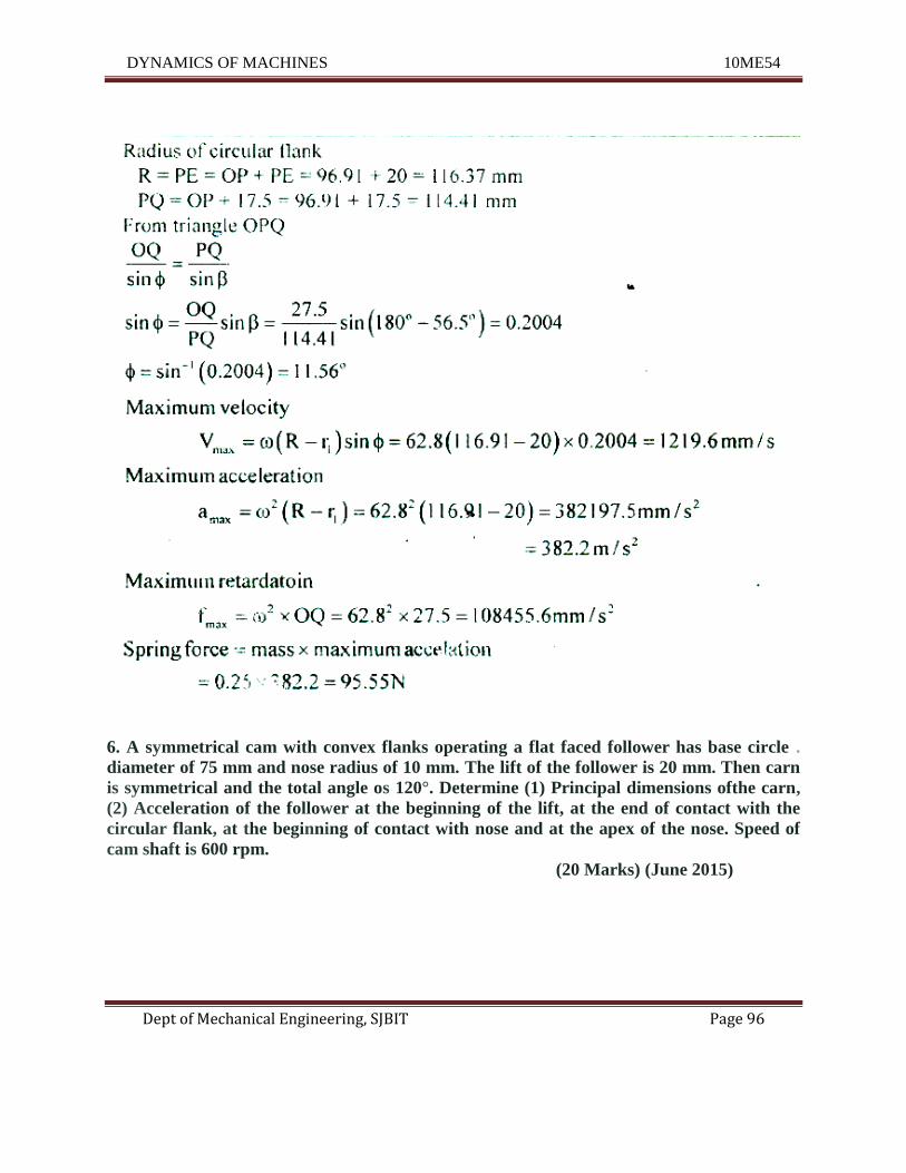
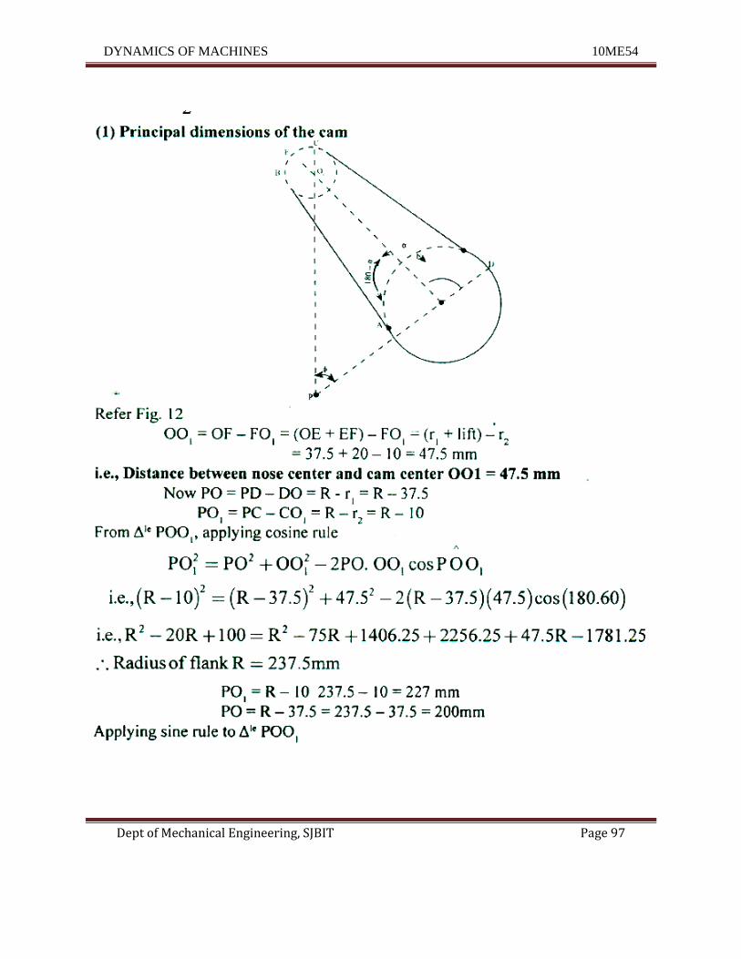
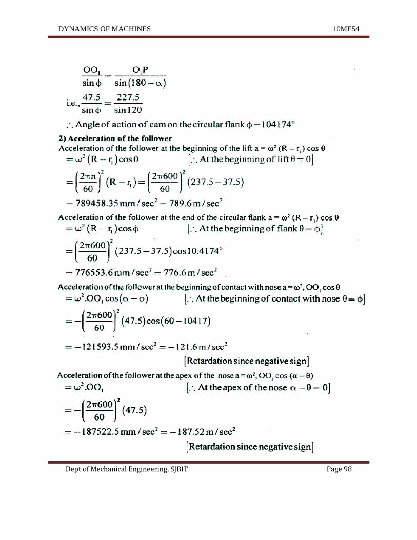
6. A symmetrical cam with convex flanks operating a flat faced follower has base circle .
diameter of 75 mm and nose radius of 10 mm. The lift of the follower is 20 mm. Then carn
is symmetrical and the total angle os 120°. Determine (1) Principal dimensions ofthe carn,
(2) Acceleration of the follower at the beginning of the lift, at the end of contact with the
circular flank, at the beginning of contact with nose and at the apex of the nose. Speed of
cam shaft is 600 rpm.
(20 Marks) (June 2015)
DYNAMICS OF MACHINES 10ME54
Dept of Mechanical Engineering, SJBIT Page 97
DYNAMICS OF MACHINES 10ME54
Dept of Mechanical Engineering, SJBIT Page 98
DYNAMICS OF MACHINES 10ME54
Dept of Mechanical Engineering, SJBIT Page 99
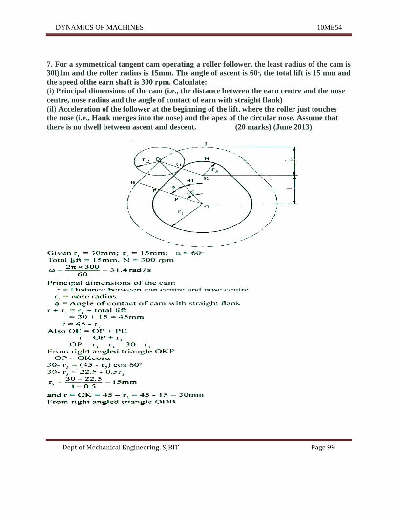
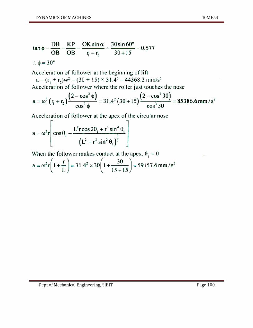
7. For a symmetrical tangent cam operating a roller follower, the least radius of the cam is
30l)1m and the roller radius is 15mm. The angle of ascent is 60·, the total lift is 15 mm and
the speed ofthe earn shaft is 300 rpm. Calculate:
(i) Principal dimensions of the cam (i.e., the distance between the earn centre and the nose
centre, nose radius and the angle of contact of earn with straight flank)
(il) Acceleration of the follower at the beginning of the lift, where the roller just touches
the nose (i.e., Hank merges into the nose) and the apex of the circular nose. Assume that
there is no dwell between ascent and descent. (20 marks) (June 2013)
DYNAMICS OF MACHINES 10ME54
Dept of Mechanical Engineering, SJBIT Page 100