Embed Size (px)
Citation preview
VTOP – an improved software for design optimization of prestressed concrete beams
S. Hernandez, D. Marcos, A. N. Fontan & J. Diaz School of Civil Engineering, University of Coruña, La Coruña, Spain
Abstract
Optimum tendon layout of prefabricated prestressed concrete beams was an early application of design optimization methodologies. However, most of the approaches found in the literature were not suitable to be implemented in real life bridge engineering. To fill the existing gap research has been conducted in past years by the authors to optimize prefabricated concrete beams formulating the problem in such a way that could be applied directly by bridge designers in beam and slab bridge decks. The software produced, labelled VTOP, contains the necessary capabilities for daily applications and possesses a user friendly graphical interface. This paper describes the problem formulation carried out and includes several examples to show the efficiency of the computer code implemented. Some of them are examples of single prefabricated concrete beams, and also an example showing the overall analysis of a bridge deck and the subsequent optimization of the prefabricated beam subjected to the internal forces produced by the external loading is included in the paper.
1 Beam and slab bridge decks
Beam and slab decks are used for a wide variety of modern bridges. Many highway overpasses or urban bridges are designed with such arrangement. While the upper slab is always made in concrete, beams can be of steel or concrete. Also concrete beams can be prefabricated or built at the bridge site at the same time than slab producing a monolithic deck. But this latter technique, while sometime common in past times, is rarely used nowadays. Currently concrete beams are made in factories by means of a delicate mixture of cement and aggregates that produces a material with quite high strength to compressive stresses. The design is completed with prestressed steel tendons that translate
Computer Aided Optimum Design in Engineering X 151
© 2007 WIT PressWIT Transactions on The Built Environment, Vol 91, www.witpress.com, ISSN 1743-3509 (on-line) doi:10.2495/OP070151

compressive forces to the concrete allowing this material to support future tensile stresses created by the bending moment originated by the external loads. Figure 1 shows two examples of beam and slab bridges, one having steel beams and other one with prefabricated concrete beams. In this paper only deck bridges built with concrete beams will be considered.
(a)
(b)
Figure 1: Beam and slab bridge decks. (a) Steel beams deck and (b) concrete beams deck.
2 Structural models of beam and slab decks
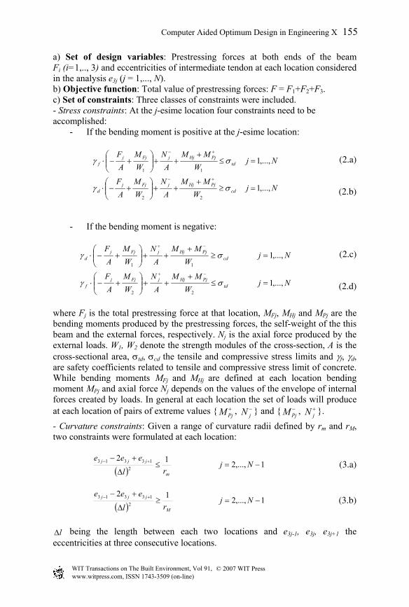
A computer picture of a beam and slab deck composed by a set of prefabricated prestressed concrete beams and an upper concrete slab is shown in Figure 2. This kind of structures needs to withstand traffic loads located at different points of the deck. Structural analysis aimed to proper dimensioning of the bridge requires create a structural model of the deck. Many approaches can be used for this purpose and it is very important to define one that can produce accurate results of the structural behaviour of the bridge and is also easy enough to be a tool for most bridge designers. This objective can be accommodated by defining a structural model composed of a two level grillage as indicated in this figure. In that grillage the top level of beams is an idealization of slab by two families of transversal and longitudinal beams. The bottom level of longitudinal elements idealizes the prefabricated beams. The set of vertical bars connecting both level of grillage are fictitious elements of great rigidity that make compatible the displacement restraints between beams and slab. With this arrangement, that represents very adequately the real behaviour of deck, the values of internal forces in slab and beams can be calculated. Bending deformation produced by external forces is supported by the deck an indicated in Figure 3. In that figure it can be observed that the total value of bending moment due to external loads is balanced not only by such kind on internal force in the slab and beams but also by a pair of compressive and tensile axial forces in slab and beam. That couple of axial forces is an important component in the internal equilibrium. Therefore the design of the prefabricated beams needs to take in account not only the bending moment but also the axial force described.
© 2007 WIT PressWIT Transactions on The Built Environment, Vol 91, www.witpress.com, ISSN 1743-3509 (on-line)
152 Computer Aided Optimum Design in Engineering X
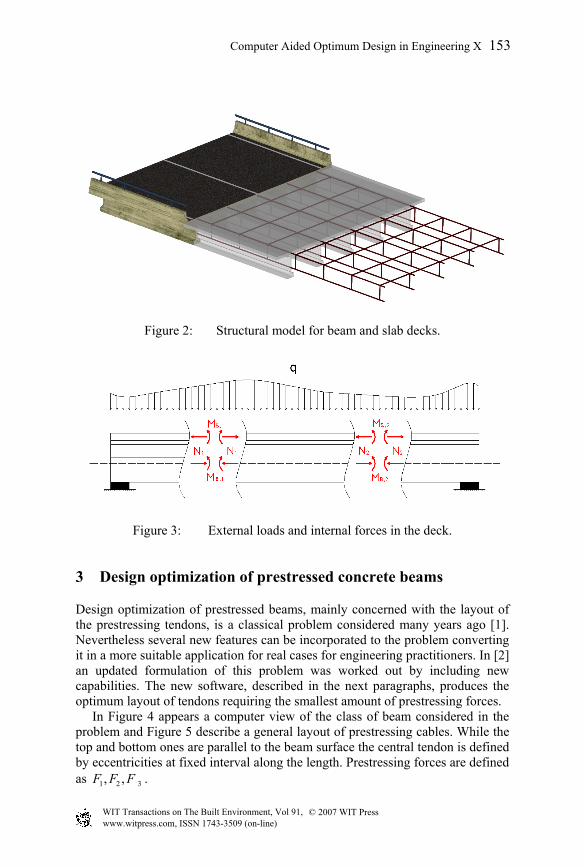
Figure 2: Structural model for beam and slab decks.
Figure 3: External loads and internal forces in the deck.
3 Design optimization of prestressed concrete beams
Design optimization of prestressed beams, mainly concerned with the layout of the prestressing tendons, is a classical problem considered many years ago [1]. Nevertheless several new features can be incorporated to the problem converting it in a more suitable application for real cases for engineering practitioners. In [2] an updated formulation of this problem was worked out by including new capabilities. The new software, described in the next paragraphs, produces the optimum layout of tendons requiring the smallest amount of prestressing forces. In Figure 4 appears a computer view of the class of beam considered in the problem and Figure 5 describe a general layout of prestressing cables. While the top and bottom ones are parallel to the beam surface the central tendon is defined by eccentricities at fixed interval along the length. Prestressing forces are defined as 1 2 3, ,F F F .
Computer Aided Optimum Design in Engineering X 153
© 2007 WIT PressWIT Transactions on The Built Environment, Vol 91, www.witpress.com, ISSN 1743-3509 (on-line)

Figure 4: Shape of prestressed concrete beams.
Figure 5: Prestressing forces and tendon eccentricities.
The problem tackled out incorporates four new features with regards to previous experiences. - Up to three prestressing tendons can be considered in the problem. - Two classes of prestressing losses can be included in the analysis. - Bending moment and axial force are taken in account in the problem. - A friendly graphical interface has been prepared to allow an easy use of the
computer code. Formulation of optimization problem is done as usual (3-7)
Min F(X) (1.a)subject to
gj (X)≤0 j=1,…,n. (1.b)
where:
© 2007 WIT PressWIT Transactions on The Built Environment, Vol 91, www.witpress.com, ISSN 1743-3509 (on-line)
154 Computer Aided Optimum Design in Engineering X
a) Set of design variables: Prestressing forces at both ends of the beam Fi (i=1,.., 3) and eccentricities of intermediate tendon at each location considered in the analysis e3j (j = 1,..., N). b) Objective function: Total value of prestressing forces: F = F1+F2+F3. c) Set of constraints: Three classes of constraints were included. - Stress constraints: At the j-esime location four constraints need to be accomplished:
- If the bending moment is positive at the j-esime location:
NjW
MMA
NWM
AF
NjW
MMA
NWM
AF
cdPjHjjFjj
d
tdPjHjjFjj
f
,...,1
,...,1
22
11
=≥+
++
+−⋅
=≤+
++
+−⋅
+−
+−
σγ
σγ (2.a)
(2.b)
- If the bending moment is negative:
NjW
MMA
NWM
AF
NjW
MMA
NWM
AF
tdPjHjjFjj
f
cdPjHjjFjj
d
,...,1
,...,1
22
11
=≤+
++
+−⋅
=≥+
++
+−⋅
−+
−+
σγ
σγ (2.c)
(2.d)
where Fj is the total prestressing force at that location, MFj, MHj and MPj are the bending moments produced by the prestressing forces, the self-weight of the this beam and the external forces, respectively. Nj is the axial force produced by the external loads. W1, W2 denote the strength modules of the cross-section, A is the cross-sectional area, σtd, σcd the tensile and compressive stress limits and γf, γd, are safety coefficients related to tensile and compressive stress limit of concrete. While bending moments MFj and MHj are defined at each location bending moment MPj and axial force Nj depends on the values of the envelope of internal forces created by loads. In general at each location the set of loads will produce at each location of pairs of extreme values { +
PjM , −jN } and { −
PjM , +jN }.
- Curvature constraints: Given a range of curvature radii defined by rm and rM, two constraints were formulated at each location:
( )1,...,212
213313 −=≤
∆
+− +− Njrl
eee
m
jjj
(3.a)
( )1,...,212
213313 −=≥
∆
+− +− Njrl
eee
M
jjj
(3.b)
l∆ being the length between each two locations and e3j-1, e3j, e3j+1 the
eccentricities at three consecutive locations.
Computer Aided Optimum Design in Engineering X 155
© 2007 WIT PressWIT Transactions on The Built Environment, Vol 91, www.witpress.com, ISSN 1743-3509 (on-line)
- Eccentricity constraints: If required by the user the values of the intermediate prestressing tendons can be fixed to constant values: e31, e3N at both ends and therefore the number of design variables is decreased by a number of two. It was mentioned earlier that prestressing loses were considered in the problem. In fact, forces F1j, F2j, F3j at location xj were defined by:
F1j = F1 e–axj F2j = F2 e
–axj F3j = F3 e–µxj 2Lx0 j ≤≤→
(4.a)
F1j = F1e–a(L–xj) F2j = F2 e
–a(L–xj) F3j = F3 e–µ(L–xj) Lx
2L
j ≤≤→
(4.b)
where a, b and µ = a(b+1) are coefficients associated with prestressing losses related with current prestressing technology. The formulation of problem given by expressions (2-4) is a nonlinear optimization problem. Nevertheless if the following changes in the design variables are made:
jjj eFY 33 ·= Nj ,...,1= 11 FYN =+ 22 FYN =+
FYN =+3 (5) The formulation becomes a linear problem that can be solved by numerical algorithms as SIMPLEX [8].
4 A software for optimal prestressing in concrete beams: VTOP
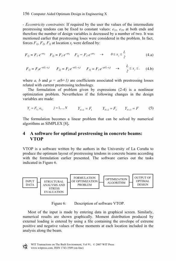
VTOP is a software written by the authors in the University of La Coruña to produce the optimum layout of prestressing tendons in concrete beams according with the formulation earlier presented. The software carries out the tasks indicated in Figure 6.
Figure 6: Description of software VTOP.
Most of the input is made by entering data in graphical screen. Similarly, numerical results are shown graphically. Moment distribution produced by external loading is entered by using a file containing the envelope of extreme positive and negative values of those moments at each location included in the analysis along the beam.
INPUT DATA
STRUCTURAL ANALYSIS AND
STRESS EVALUATION
FORMULATION OF OPTIMIZATION
PROBLEM
OPTIMIZATION ALGORITHM
OUTPUT OF OPTIMAL DESIGN
© 2007 WIT PressWIT Transactions on The Built Environment, Vol 91, www.witpress.com, ISSN 1743-3509 (on-line)
156 Computer Aided Optimum Design in Engineering X

Many graphical screens are provided to the user for entering data required for the analysis and optimization. Amount them: - Screen of cross-section beam data. - Screen of prestressing forces and overall layout - Screen of internal forces distribution. - Screen of set of constraints considered in the optimization problem. - Screen of optimal layout of tendons. - Screen of value of optimal prestressing forces. - Screen of set of active constrains at the optimum. Most of them will be shown in the following examples devoted to describe the capabilities of this computer code.
Figure 7: Cross-section of example 1.
5 Application examples
5.1 Beam subjected to isolated loads
In Figure 7 appears the cross section of the beam subjected to a couple of vertical loads and axial forces described in Figure 8. The remaining data defining the problem are:
Beam depth: 0.8 m; top flange width: 0.8 m; bottom flange width: 0.6 m. Beam length: L= 30 m.; Number of locations included in the analysis: 11. Concrete unit weight: 25 KN/m2. Compressive stress limit: 40 MPa; tensile stress limit: 0 MPa Prestressing losses coefficients; a=0.00225; b=0.55; bonding value: 0.03 m.
Computer Aided Optimum Design in Engineering X 157
© 2007 WIT PressWIT Transactions on The Built Environment, Vol 91, www.witpress.com, ISSN 1743-3509 (on-line)

Eccentricity of intermediate tendon at both ends: 0.2 m. Curvature radii limits: ± 20 m. Loads considered: Axial force: 35 KN; isolated loads at L/3 and 2L/3: 160 KN.
Figure 8: External loads considered.
Figure 9: Optimal tendon layout.
The layout of optimal tendons appears in Figure 9. It can be observed that the top tendon is not necessary for the set of loads considered. Also, numerical
© 2007 WIT PressWIT Transactions on The Built Environment, Vol 91, www.witpress.com, ISSN 1743-3509 (on-line)
158 Computer Aided Optimum Design in Engineering X
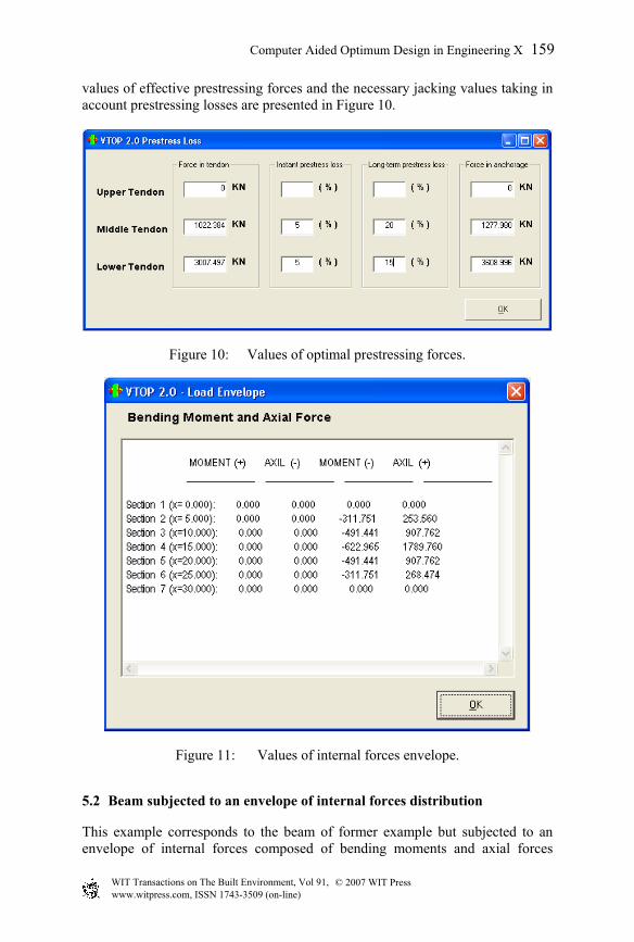
values of effective prestressing forces and the necessary jacking values taking in account prestressing losses are presented in Figure 10.
Figure 10: Values of optimal prestressing forces.
Figure 11: Values of internal forces envelope.
5.2 Beam subjected to an envelope of internal forces distribution
This example corresponds to the beam of former example but subjected to an envelope of internal forces composed of bending moments and axial forces
Computer Aided Optimum Design in Engineering X 159
© 2007 WIT PressWIT Transactions on The Built Environment, Vol 91, www.witpress.com, ISSN 1743-3509 (on-line)
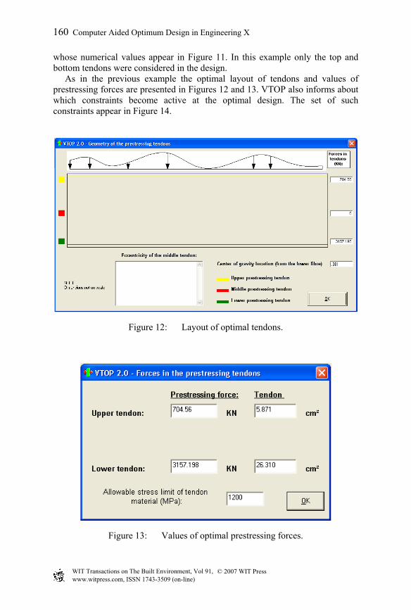
whose numerical values appear in Figure 11. In this example only the top and bottom tendons were considered in the design. As in the previous example the optimal layout of tendons and values of prestressing forces are presented in Figures 12 and 13. VTOP also informs about which constraints become active at the optimal design. The set of such constraints appear in Figure 14.
Figure 12: Layout of optimal tendons.
Figure 13: Values of optimal prestressing forces.
© 2007 WIT PressWIT Transactions on The Built Environment, Vol 91, www.witpress.com, ISSN 1743-3509 (on-line)
160 Computer Aided Optimum Design in Engineering X

Figure 14: Set of active constraints at optimum design.
(a)
(b)
Figure 15: Bridge deck and prefabricated beam. (a) Bridge deck and (b) Prefabricated beam.
Computer Aided Optimum Design in Engineering X 161
© 2007 WIT PressWIT Transactions on The Built Environment, Vol 91, www.witpress.com, ISSN 1743-3509 (on-line)
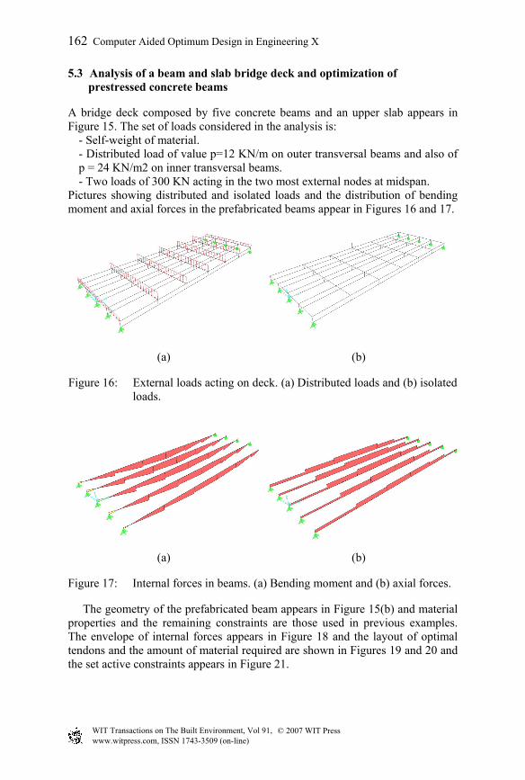
5.3 Analysis of a beam and slab bridge deck and optimization of prestressed concrete beams
A bridge deck composed by five concrete beams and an upper slab appears in Figure 15. The set of loads considered in the analysis is:
- Self-weight of material. - Distributed load of value p=12 KN/m on outer transversal beams and also of p = 24 KN/m2 on inner transversal beams. - Two loads of 300 KN acting in the two most external nodes at midspan.
Pictures showing distributed and isolated loads and the distribution of bending moment and axial forces in the prefabricated beams appear in Figures 16 and 17.
(a) (b)
Figure 16: External loads acting on deck. (a) Distributed loads and (b) isolated loads.
(a) (b)
Figure 17: Internal forces in beams. (a) Bending moment and (b) axial forces.
The geometry of the prefabricated beam appears in Figure 15(b) and material properties and the remaining constraints are those used in previous examples. The envelope of internal forces appears in Figure 18 and the layout of optimal tendons and the amount of material required are shown in Figures 19 and 20 and the set active constraints appears in Figure 21.
© 2007 WIT PressWIT Transactions on The Built Environment, Vol 91, www.witpress.com, ISSN 1743-3509 (on-line)
162 Computer Aided Optimum Design in Engineering X

Figure 18: Envelope of internal forces.
Figure 19: Layout of optimal prestressing tendon.
Figure 20: Amount of steel required for optimal tendons.
Computer Aided Optimum Design in Engineering X 163
© 2007 WIT PressWIT Transactions on The Built Environment, Vol 91, www.witpress.com, ISSN 1743-3509 (on-line)

Figure 21: Set of active constraints at optimum.
6 Conclusions
A few conclusions can be extracted from the work carried out: - Design of prestressing beam in a appropriate case for application of
structural optimization methodologies. - Optimum layout of prestressing tendons can be formulated as a linear
optimization problem. - User friendly software can help in introducing new design techniques. The
software VTOP, with its graphical interface makes easy to obtain the optimal solution of the problem studied.
References
[1] Kirch, U.: Optimized prestressing by Linear Programming. Int. J. Num. Meth. Eng., vol. 7, 1973,pp. 125-136
[2] Hernandez S. & Fontan A.N.: Practical Applications of Design Optimization. WIT Press, 2002.
[3] Arora, J.: Introduction to Optimum Design. Macgraw-Hill, 1989. [4] Hernandez S. (ed.): Advanced Techniques in the Optimum Design of
Structures. Computational Mechanics, 1993. [5] Kirch, U.: Structural Optimization. Springer Verlag, 1993. [6] Vanderplaats, G.N.: Numerical Optimization Techniques for Engineering
Design: With Applications. Macgraw-Hill, 1984. [7] Haftka, R.T., Gürdal, Z. & Kamat, M.P.: Elements of Structural
Optimization. Kluwer Academic Press, 1990. [8] Dantzig, G.: Linear Programming and Extensions. Princeton University
Press, 1963.
© 2007 WIT PressWIT Transactions on The Built Environment, Vol 91, www.witpress.com, ISSN 1743-3509 (on-line)
164 Computer Aided Optimum Design in Engineering X