Embed Size (px)
Citation preview

ENSKF VectoLub,
VTEC range
Operating manual
VTEC

ENPage 1
951-130-440, edition 06/2009
Imprint
The operating manual is part of the scope of supply of the SKF VectoLub modular minimal quantity lubrication system. The product will be named in the operating manual as the minimal quantity lubrication (MQL) VTEC system.
The manual has been edited in conformity with applicable standards and rules for technical documentation.
© Copyright
SKF reserves the right to make changes to adapt to technical improvement.
Reprinting or copying even of parts of this manual requires the permission of SKF.
ContentS
Contents
Imprint ............................................................. 1ontent ................................................................... Introduction .................................................... 3Notes on the Operating Manual .................. 3Safety instructions ......................................... 4Applications .................................................... 5Lubricants ....................................................... 5Delivery ........................................................... 6Transport and Storage .................................. 6Versions ........................................................... 7Design ............................................................. 8nction ............................................................. 10
Master module and slave module ......... 10Installation .................................................... 12
Setup ......................................................... 12Connection ................................................ 12
Lubricant inlet connection .......................... 12r inlet connection ......................................... 12Connection of the coaxial line to the outlet port 13Connection of the coaxial line to the projection block .............................................................. 14Electrical connection .................................. 15
General air solenoid valve and air solenoid valve for micropump ............................... 15Lubricant flow sensor GS304P .............. 15Pressure switch ........................................ 15
cropump flow rate adjustment ................... 16Adjustment with thumb wheel .............. 16Adjustment with metering ring ............. 16Neutralizing the micropump delivery ... 17
justment of the pneumatic pulse generator ... 17Carrier air pressure regulator .................... 17eeding and commissioning ......................... 19
Commissioning ......................................... 19Bleeding the unit .................................... 19Bleeding the micropump ........................ 19Switching out a nozzle ............................ 19
intenance ...................................................... 20ults ................................................................. 20are parts* ..................................................... 23acing out of service ..................................... 24
Temporary standstill ................................ 24Final standstill .......................................... 24
Service .......................................................... 26

EN Page 2
951-130-440, edition 06/2009
CLARATION DE CONFORMITÉ / COMFORMITY STATEMENT(Article/Article 4 paragraphe/section 2 directive Européenne/European guideline 98/37/CE)
Le fabricant / The manufacturer: SKF Lubrication Systems France SAS - rue Robert Amy - 49400 SAUMUR (FRANCE)Déclare que le matériel / states that the following material:
SKF VectoLub, external Minimal Quantity Lubrication, VTEC range
- fait l’objet d’une interdiction de mise en service avant que la machine dans laquelle il sera incorporé n’aura été declarée conforme aux dispositions de la directive 98/37/ce et a la lég-islation nationale la transposant / shall not be started before the machine to be fitted out was stated as conforming to the dispositions of the guideline 98/37/ce and thus to the relevant national guidelines,- est conforme aux dispositions des directives européennes suivantes / conforms with the dispositions f the following european guidelines :
- commentaires / further comments:
Certificat original, établi à/Original certificate, made in: SAUMUR (Maine & Loire - FRANCE) Date: 01 juillet 2005 Signataire/Signature Fonction/Function
Guillaume AMILIEN Responsable Développement / Product Development Manager
Conformity statement
Ce matériel est étudié pour être employé dans certaines limites de tension et installé selon les conditions précisées dans les documents accompagnant sa livraison. Son incorporation ou/et son assemblage doit être effectué conformément entre-autres aux règles EN60.439 "Équipement électrique des machines"./ The above-mentioned equipment was designed to be used within a defined voltage range, and under the conditions given in the literature provided in the delivery volume. The incorporation and/or assembly shall be performed in accordance with the rules EN60.439 "Electric machines equipment", among others.
N° 73/23/CEE (19/02/73) modifiée par la directive/modified through 93/68/CEE (22/07/93) N° 89/336/CEE (03/05/89) modifiée par la directive/modified through 93/68/CEE (22/07/93) pour les composants électriques et/ou électroniques/As far as electric and/or electronic components are concerned.

ENPage 3
951-130-440, edition 06/2009
Introduction
The VTEC system is remarkable in its opera-tional reliability and long service life. The lubrication system is made in conformity with the generally recognized rules of technology and the applicable safe working practices and the rules for accident prevention. Still hazards may be involved in its use, which can lead to injury of operators or other persons or damage the machine or other property.
To ensure trouble-free operation and prevent hazard, we kindly ask you to read the pres-ent manual carefully and observe the notes contained in it.
Notes on the Operating Manual
Text marked with this sign alerts to special hazards or work that must be performed with caution.
Keep the operating manual in a safe place so that it is always available wherever the system is in use.
This operating manual is part of the system, and it must be given to the operating company upon sale of the system.
Introduction

EN Page 4
951-130-440, edition 06/2009
Safety instructions
Please comply with the following safety instructions in order to prevent possible damage and to ensure that the VTEC system works properly.
Use the VTEC system only in technically perfect condition for its intended use. Be aware of hazards and observe the operating manual.
Especially errors that could affect safety must be resolved without delay.
Safety measures corresponding to the parameters of the lubricant supplied must be stipulated.
The safety mechanisms must not be damaged, dismantled, or in any way made inoperable, nor must they be replaced by parts which have not been expressly approved of by SKF.
The electrical connection and all interventions such as repairs, component replacement, etc. may be carried out only by properly qualified and instructed personnel.
If systems are improperly connected, substantial material or personal damage my be the consequence.
Repair work may be carried out only after a trained specialist has disconnected the system from power.
Working on VTEC systems under electrical voltage could lead to per-sonal injury.
Working on systems under pressure could lead to personal injury.
Unauthorized modifications to the VTEC system and the use of unau-thorized spare parts and aids are prohibited and disqualify the war-ranty.
Worn-out systems must be made inoperable and disposed of properly.
Safety instructions

ENPage 5
951-130-440, edition 06/2009
Applications
All products from SKF may be used only for their intended purpose as described in this brochure and in any instructions. If operating instructions are supplied with the products, they must be read and followed.
Not all lubricants are suitable for use in centralized lubrication systems. SKF does offer an inspection service to test customer supplied lubricant to determine if it can be used in a centralized system. SKF lubrica-tion systems or their components are not approved for use with gases, liquefied gases, pressurized gases in solution and fluids with a vapor pressure exceeding normal atmospheric pressure (1013 mbars) by more than 0,5 bar at their maximum permissible temperature.
Hazardous materials of any kind, especially the materials classified as hazardous by European Community Directive EC 67/548/EEC, Article 2, Par. 2, may only be used to fill SKF centralized lubrication systems and components and delivered and/or distrib-uted with the same after consulting with and receiving written approval from SKF.
The VTEC system works with pneumatic actu-ated micropumps and delivers lubricant to the lubrication point via projection nozzles. Other use or use beyond this purpose is considered unintended. SKF will not accept liability for damages resulting from such unintended use.
Only authorized lubricants for the system may be supplied. Unsuitable lubricants could lead to the system failing and possibly severe properly damage and personal injury.
Lubricants
The VTEC system can supply lubricants with the following effective viscosity:
mineral or synthetic oil, ecological oil, • with an effective viscosity between 10 and 400 mm2/s.
A list of authorized lubricants is available on the website: www.skf.com/lubrication. The lubricants recommended correspond in their composition to customary safety regulations, and they are suitable for use in MQL systems.
Whenever using other lubricants, keep in mind that there are lubricants which, although within the authorized limits, nevertheless are unsuitable for lubrication systems because of their characteristics. Consult the SKF Service center.
Keep in mind that lubricants are environ-mentally unfriendly substances and that their transport, storage and processing require that special safety measures be taken.
Applications

EN Page 6
951-130-440, edition 06/2009
Delivery
Upon receiving the package please check the items for possible damage, and ensure the package is complete by checking the supply papers.
Keep the packaging material until any and all problems have been clarified.
Transport and Storage
There are no restrictions on transportation by land, air and sea.
In general, the system should be stored in a dry and dust-free environment. The storage temperatures are between –10 °C and +40 °C.
Delivery

ENPage 7
951-130-440, edition 06/2009
Versions
The VTEC system is a modular system, which can comprise up to 8 modules. These modules corresponds to bases with various functions († page 8).
Every model of a VTEC unit has a codification, which the user has indicated when ordering.
In order to easy identify the current VTEC unit and to know its different functions, we suggest you to write down the unit codification given when the order has been placed. The table beside will help you to identify every module of the VTEC unit and the different functions.
The codification system is the same for every module. A module has a three-characters ref-erence. The first module is always the one with the lubricant and compressed air inlets.
The last three numbers of the codification cor-respond to the voltage key of the VTEC unit:
+ 428 : 230 V, 50/60 Hz + 429 : 115 V, 50/60 Hz + 924 : 24 V DC
VTEC . . . . . . . . . . . . . . . . . . . . . . . . + . . .
Versions
First character
A ............... base aloneB .............. base with pneumatic pulse generatorC ............... base with air solenoid valveD .............. base with pneumatic pulse generator + air solenoid valveE ............... base + GS304P aloneF ............... base + GS304P with pneumatic pulse generatorG ............... base + GS304P with air solenoid valveH .............. base + GS304P with pneumatic pulse generator + air solenoid valveI ................ base with general air solenoid valveJ ............... base alone (directly controlled by base ‘I’)K ............... base + GS304P alone (directly controlled by base ‘I’)
Second character
A ............... micropump, metering ring, flow rate 3 to 30 mm3/strokeB .............. micropump, thumb wheel, flow rate 3 to 30 mm3/strokeC ............... micropump, metering ring, stainless steel, flow rate 3 to 30 mm3/strokeD .............. micropump, thumb wheel, stainless steel, flow rate 3 to 30 mm3/strokeE ................ micropump, metering ring, flow rate 3 to 90mm3/strokeF ................ micropump, thumb wheel, flow rate 3 to 90mm3/strokeG ................ micropump, metering ring, stainless steel, flow rate 3 to 90 mm3/strokeH ............... micropump, thumb wheel, stainless steel, flow rate 3 to 90 mm3/strokeZ ............... no micropump (only with base ‘I’ – general air solenloid valve)
Third character
Z ............... no air monitoring M .............. air flow monitoring with manometerP ............... air flow monitoring with pressure switch

EN Page 8
951-130-440, edition 06/2009
Design
The VTEC unit is a modular lubrication system comprising up to 8 different modules. The unit is mounted on a standard fixing rail.
Figure 1 shows one model of a VTEC unit with 7 different modules. Every module has a base with different functions.
This is a front side view with the compressed air and lubricant inlets on the left side.
The VTEC unit has one lubricant inlet with quick-release connector, and two compressed air inlet with quick-release connector.
But only one air inlet port is used, the other being closed with a screw plug. The lower air inlet port is used when the first module has a “i” base (with a general air solenoid valve). The upper inlet port is used with every other bases.
Except the “I” base, with the general air sole-noid valve, all other bases work in the same way.
Every module has on the top an outlet port for coaxial hose - air and lubricant - with two quick-release connectors. The quick-release
connector for the capillary tube (lubricant) is located beneath the quick-release connector for the outer tube (air). The user can set the carrier air pressure with a pressure regulator. The air flow can be monitored either with a manometer or with a pressure switch.
A pneumatic micropump is mounted under every module. The user can adjust the flow rate of the pump with metering rings or with a thumb wheel.
A module can have up to three different addi-tional equipment on the front side:
a pneumatic pulse generator to adjust the • delivery frequency of the micropump
an air solenoid valve to control the air inlet • for the pneumatic micropump.
a flow sensor, type GS304P, to monitor the • oil flow of the module.
Every module can have one, two or three of the equipment, and even none. According to the equipment a module is “slave” or “master”.
Design

ENPage 9
951-130-440, edition 06/2009
Fig. 1 Overview of a VTEC unit
A standard fixing railB fixing clipsC manometer, general air monitoringC’ manometer, carrier air monitoringD coaxial outlet port (air and oil)E pressure switch, carrier air monitoringF carrier air pressure regulatorG air inlet port H air inlet port (module with a general air sole-noid valve)I Lubricant inletJ General air solenoid valveK Pneumatic pulse generatorL pneumatic micropump setting with thumb wheelM pneumatic micropump setting with metering ringN air solenoid valve - controls air of the micro-pumpO pneumatic pulse generator and an air solenoid valve (control of micropump) put together with a connection plateP base without additional equipment (A)Q oil flow sensor GS304P R base without additional equipment (J)
Design
Model: VTEC-IZM-BBM-CAZ-DBP-ABZ-HBM-JAZ+ 924
A B C D E F
G H I J K L M ON P R
C’
Q

EN Page 10
951-130-440, edition 06/2009
Fig. 2 Projection nozzle
Function
When the VTEC unit is switched on, it is sup-plied with compressed air (5 to 7 bars) and with lubricant (0,1 to 0,5 bar).
The lubricant flows through the different bases to the volumetric pneumatic micropump. The delivery frequency of the micropump( max. 3 stroke/s) is independently adjusted with either a pneumatic pulse generator or a solenoid valve, which is controlled via a control unit. The flow rate of the micropump can be adjusted with metering rings or with a thumb wheel.
The micropump delivers a metered quantity of lubricant, which goes through inner channel of the base to the coaxial outlet port. The lubri-cant flow can be monitored at the micropump outlet with a flow sensor type GS304P.
The compressed air also flows through the different bases and is divided in two ways in each of them. Some compressed air is supplied to the micropump to actuate it. The other part of the compressed air (called carrier air) is supplied to the coaxial outlet port and goes through the outer tube of the hose. The carrier air pressure of every base can be adjusted with a pressure regulator. This pressure can be also monitored by means of a manometer or a pressure switch.
The low-pressure carrier air and lubricant are simultaneously transported via the coaxial hose to the nozzle. The carrier air is swirled in the nozzle. As a result, the metered quantity of lubricant is broken down into microdroplets, which are transported by the carrier air to the friction point without causing any mist. The microdroplet size (200/600 μm) ensures a perfect lubricant coating without atomization.
Function
Master module and slave module
When a VTEC unit is seen from the front side (as on figure 1), the first module is on the left side with lubri-cant and air inlets – module position order from left to right.
When a module doesn’t have one (or several) of the control equipments (general air solenoid valve, air solenoid valve or pneumatic pulse generator) it will depend for this function on the module mounted upstream, which has the equipment(s). The upstream module with the equipment is called ‘master module’ and the other ‘slave module’.
Table 1 shows the different modules with their main functions according to their equipment.
1 2 3
carrier air1. lubricant2. turbulence zone3.

ENPage 11
951-130-440, edition 06/2009
Function
Table 1 Description of the different bases with their main equipment and functions.
Base alone (A) This base has no additional function. It is always used as slave of the master base positioned upstream.Base with a pneumatic pulse generator (B) The pulse generator adjusts the working frequency of the micropump. A base with an air solenoid valve,
positioned upstream, controls the air inlet, which actuates the micropump.Base with an air solenoid valve (C) The air solenoid valve controls the micropump. The micropump working frequency is adjusted by the
solenoid valve, which is controlled by a control unit.Base with a pneumatic pulse generator and an air solenoid valve (D)
The air solenoid valve controls the micropump and the pulse generator adjusts the working frequency of the micropump.
Base with only a flow sensor GS304P (E) The flow sensor GS304P monitors the lubricant outflow of the micropump. This base has no other addi-tional function. It is always used as slave of the master base positioned upstream.
Base with a flow sensor GS304P and a pneu-matic pulse generator (F)
The flow sensor GS304P monitors the lubricant outflow of the micropump. The pulse generator adjusts the working frequency of the micropump. A base with an air solenoid valve, positioned upstream, controls the air inlet, which actuates the micropump.
Base with a flow sensor GS304P and an air solenoid valve (G)
The flow sensor GS304P monitors the lubricant outflow of the micropump. The air solenoid valve controls the micropump. The micropump working frequency is adjusted by the solenoid valve, which is controlled by a control unit.
Base with a flow sensor GS304P, a pneumatic pulse generator and an air solenoid valve (H)
The flow sensor GS304P monitors the lubricant outflow of the micropump. The air solenoid valve controls the micropump and the pulse generator adjusts the working frequency of the micropump.
Base with general air solenoid valve (I) The air general solenoid valve controls the air inlet for the pneumatic micropumps as well as the carrier air inlet. This base is always master of the other bases which are placed downstream.
Base alone (J) This base has no additional function. This base has no additional function. It is always slave of a base with a solenoid valve for general air (I).
Base with only a flow sensor GS304P (K) The flow sensor GS304P monitors the lubricant outflow of the micropump. This base has no other addi-tional function. This base has no additional function. It is always slave of a base with a solenoid valve for general air (I).

EN Page 12
951-130-440, edition 06/2009
Fig. 3 Inlet ports
Air inlet connection
For the good function of a VTEC unit, the air pressure inlet shall not exceed 7 bars.
Compressed air is supplied to the VTEC unit via a Ø8 tube and a quick release coupling (2).
According to the base of the first module (with a general air solenoid valve as shown in fig. 3 or not), the quick-release connector for compressed air is not at the same place. The unused air inlet port is closed with a screw plug.
Insert the hose into the quick-release • coupling
Pull carefully on the hose to check it is cor-• rectly held by the coupling.
Installation
Setup
Before installing a VTEC unit, remove the packaging material as well as any transport safety devices (e.g. sealing plug in the open outlet).
The VTEC unit should be installed in a location that is protected from moisture and vibration, but should be readily accessible to ensure all further installation tasks can be performed easily.
The VTEC unit can be delivered either in a protective housing (option) or simply mounted on a standard fixing rail by means of the fixing clips on the backside.
Connection
The lubricant and compressed air inlet lines are connected to a VTEC unit on the first module (left side when unit seen from the front side as on Fig. 1), which has two quick-release connectors.
Lubricant inlet connection
Lubricant is supplied to the VTEC unit via a Ø8 tube and a quick release coupling (1).
Insert the hose into the quick-release • coupling
Pull carefully on the hose to check it is cor-• rectly held by the coupling.
Installation, inlets
1
2
3
Lubricant inlet1. air inlet (base with general air 2.
solenoid valve)air inlet (other bases)3.

ENPage 13
951-130-440, edition 06/2009
Pull out (ca. 10 cm) the capillary tube from • the coaxial line
Insert the capillary tube into the outlet port • and fit it to the lower quick-release connec-tor.
Pull slightly the capillary tube to check it is • correctly held.
The coaxial line may be only con-nected by authorized and trained specialists.
The coaxial line has first to be con-nected to the outlet port of the module, and then to the nozzle.
It is recommended to identify the coaxial line in accordance with the nozzle it supplies, e.g. with colors or with labels.
The coaxial line (from 1 to 5 m*) is connected to the module outlet port († fig. 4) by means of quick-release connectors. Every outlet port has two coaxial coupling († fig. 5).
The lower connector holds the capillary tube of the line. The upper connector (orange collar) holds the outer tube of the coaxial line. *) For greater line length, please contact the SKF service
center.
Installation, outlets
Connection of the coaxial line to the outlet port
Fig. 6
Insert the outer tube into the outlet port • and fit it to the upper quick-release connec-tor.
Pull slightly the outer tube to check it is • correctly held.
Fig. 7
Fig. 4
module
outlet port
Fig. 5 Crosssection view of the outlet port
1 3
42
upper quick-release connector1. lower quick-release connector2. outer tube of the coaxial line3. capillary tube of the coaxial line4.

EN Page 14
951-130-440, edition 06/2009
Installation, nozzles
1/ • Unscrew and remove the nozzle (1) from the end tube (rigid or articulated) (3). • Slip the capillary (7) into the quick connector (6) of the fixing block (5) until it is coming out of the end tube (3).
2/ • Insert the outer tube (8) of the coaxial hose (9) into the quick connector (6) of the fixing block (5). • Pull carefully the hose (9) to check that the outer tube (8) is correctly fixed. • Stretch the capillary tube (7) from the end tube (3) and cut it (15 to 25 mm out of the tube). Maintain the capillary tube otherwise it will retract.
3/ • Insert the capillary tube (7) into the quick connector (10) of the nozzle (1). • Pull carefully the capillary tube (9) to check it is correctly fixed.
4/ • Screw in and tighten the nozzle (1) onto the end tube (3).
The coaxial line may be only con-nected by authorized and trained specialists.
The coaxial line can be connected to the projection block only if it is already connected to the outlet port of the module.
The length of the coaxial line between the outlet port of the module and the nozzle has to be between 1 and 5 m. For greater length, please contact the SKF service center.
1 2 3 5 6 7 8 9
nozzle1. union end tube - nozzle2. end tube3. union fixing block - end tube4. fixing block5. quick-release connector6. capillary tube of the coaxial line7. outer tube of the coaxial line8. coaxial line9. quick-release connector10.
>15 to 25< mm10 Fig. 9
Fig. 10
Fig. 11
Fig. 84
Connection of the coaxial line to the projection block

ENPage 15
951-130-440, edition 06/2009
Lubricant flow sensor GS304P
Figure 14 shows the wiring diagram and the assignment of the cable leads or round con-nector pins for the flow sensor. For any other information about the electric connection, please refer to the technical data.
The lubricant flow sensor only works with direct current (voltage key +924)
Installation, electric connection
Fig. 14 GS304P flow sensor wiring diagram
Electrical connection
The VTEC system may be con-nected only by properly qualified and instructed personnel. Comply with the notes in this operating manual.
General air solenoid valve and air solenoid valve for micropump
Wiring depends on the operating voltage of the solenoid valve. The voltage key at the end of the VTEC number indicates the operating voltage.
The supply voltage on site must agree with the information on the codification of the VTEC unit. Check the fusing of the circuit. Use only the origi-nal fuse with the required ampere value. If other fuses are used, damage to property of personal injury may be the consequence.
VTEC unit with the following voltage keys: • +428 (230V AC, 50/60Hz) or • +429 (115V AC, 50/60Hz)
VTEC unit with the following voltage keys: • +924 (24V DC)
+�
��
Fig. 12 Solenoid valve wiring diagram
Fig. 13 Solenoid valve wiring diagram Pressure switch
Pressure switches are 2 leads on/off switches (oper-ating voltage 24 V DC)
Pin 1 (BN - brown): + 24 VPin 2 (WH- white): PNP/NC – opens in event of flowPin 3 (BU – blue): 0 VPin 4 (BK – black): PNP/NO – closes in event of flow
EN Page 16
951-130-440, edition 06/2009
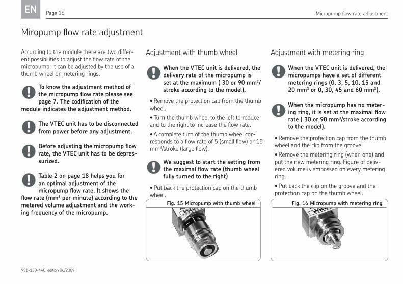
Fig. 16 Micropump with metering ringFig. 15 Micropump with thumb wheel
According to the module there are two differ-ent possibilities to adjust the flow rate of the micropump. It can be adjusted by the use of a thumb wheel or metering rings.
To know the adjustment method of the micropump flow rate please see page 7. The codification of the module indicates the adjustment method.
The VTEC unit has to be disconnected from power before any adjustment.
Before adjusting the micropump flow rate, the VTEC unit has to be depres-surized.
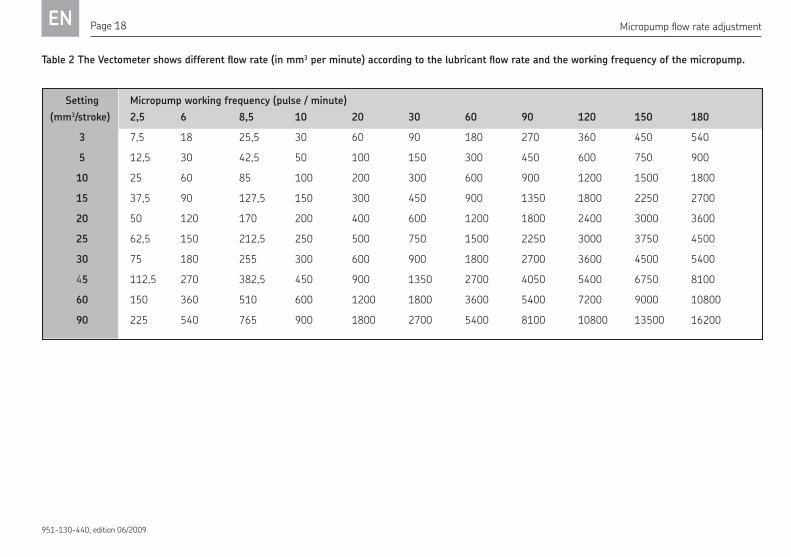
Table 2 on page 18 helps you for an optimal adjustment of the micropump flow rate. It shows the flow rate (mm3 per minute) according to the metered volume adjustment and the work-ing frequency of the micropump.
Micropump flow rate adjustment
Adjustment with thumb wheel
When the VTEC unit is delivered, the delivery rate of the micropump is set at the maximum ( 30 or 90 mm3/stroke according to the model).
Remove the protection cap from the thumb • wheel.
Turn the thumb wheel to the left to reduce • and to the right to increase the flow rate.
A complete turn of the thumb wheel cor-• responds to a flow rate of 5 (small flow) or 15 mm3/stroke (large flow).
We suggest to start the setting from the maximal flow rate (thumb wheel fully turned to the right)
Put back the protection cap on the thumb • wheel.
Adjustment with metering ring
When the VTEC unit is delivered, the micropumps have a set of different metering rings (0, 3, 5, 10, 15 and 20 mm3 or 0, 30, 45 and 60 mm3).
When the micropump has no meter-ing ring, it is set at the maximal flow rate ( 30 or 90 mm3/stroke according to the model).
Remove the protection cap from the thumb • wheel and the clip from the groove.
Remove the metering ring (when one) and • put the new metering ring. Figure of deliv-ered volume is embossed on every metering ring.
Put back the clip on the groove and the • protection cap on the thumb wheel.
Miropump flow rate adjustment

ENPage 17
951-130-440, edition 06/2009
Adjustment of the pneumatic pulse generator
Some modules might have a pneumatic pulse generator. With this pneumatic pulse generator it is possible to adjust the micropump working frequency of the module and of the following slave modules.
The frequency is indicated on the pulse gen-erator in pulses (piston stroke) per second.
Fig. 17 Pulse generator setting scale
Use a slotted screwdriver to adjust the • pneumatic pulse generator.
Micropump working frequency
Neutralizing the micropump delivery
The micropump lubricant outflow can be neu-tralized at any time.
For the micropump with adjustment of the flow rate with thumb wheel: fully turn the thumb wheel to the left.
For the micropump with adjustment of the flow rate with metering rings: replace the current metering ring (when there is one) by the ‘0’ metering ring.
The ‘0’ metering ring is very impor-tant in order to neutralize the micropump lubricant outflow. Do not lose it.
Carrier air pressure regulator1. counter nut2.
Carrier air pressure regulator
Every module has on the top a carrier air pressure regulator. According to the needs of the nozzle corresponding to this module, it is possible to increase or reduce this carrier air pressure.
Turn the regulator to the left (front view • of the module as in page 9) to build up the pressure and to the right to reduce it.
When the pressure regulator is com-pletely turned to the right, there is no more carrier air flow.
Loosen the counter nut to block the flow • regulator in order to prevent any accidental modification of the pressure.
1
2
Fig. 18 Pressure regulating valve
EN Page 18
951-130-440, edition 06/2009
Micropump flow rate adjustment
Table 2 The Vectometer shows different flow rate (in mm3 per minute) according to the lubricant flow rate and the working frequency of the micropump.
Setting Micropump working frequency (pulse / minute)
(mm3/stroke) 2,5 6 8,5 10 20 30 60 90 120 150 180
3 7,5 18 25,5 30 60 90 180 270 360 450 540
5 12,5 30 42,5 50 100 150 300 450 600 750 900
10 25 60 85 100 200 300 600 900 1200 1500 1800
15 37,5 90 127,5 150 300 450 900 1350 1800 2250 2700
20 50 120 170 200 400 600 1200 1800 2400 3000 3600
25 62,5 150 212,5 250 500 750 1500 2250 3000 3750 4500
30 75 180 255 300 600 900 1800 2700 3600 4500 5400
45 112,5 270 382,5 450 900 1350 2700 4050 5400 6750 8100
60 150 360 510 600 1200 1800 3600 5400 7200 9000 10800
90 225 540 765 900 1800 2700 5400 8100 10800 13500 16200

ENPage 19
951-130-440, edition 06/2009
Fig. 19 View of the last module
Bleeding and commissioning
Before starting the VTEC unit, check that all outer connections (reservoir, air supply, lube lines to the nozzles...) have been well mounted and tightened.
CommissioningBleed the VTEC unit before starting.• Set the micropump metered volume ac-•
cording to the needs.
To ensure the good function of the micropumps with thumb wheel, the minimal flow rate has to be above 7 mm3/stroke.
Set the micropump working frequency ac-• cording to the needs.
When the VTEC unit is in operation, you can adjust the carrier air pressure at any time with the air pressure regulator. With a higher flow rate, you get a finer atomization of the lubri-cant, and the lubrication is then more homo-geneous all over the surface to be lubricated.
If the carrier air pressure is to high, there will be a problem with the atomization. The lubricant particles would be too fine and may keep suspended in the air.
Commissioning
Bleeding
To correctly bleed a VTEC unit, first bleed the unit itself and the bleed the micropumps.
Bleeding the unit Unscrew and remove the screw plug, which •
is closing the lubricant duct of the last mod-ule of the VTEC unit.
Feed the unit with lubricant until it comes • out without air bubbles.
Put back and tighten the screw plug.•
Bleeding the micropumpSet all the micropumps to their maximal •
flow rate.Let the micropumps operate unit lubricant •
is coming out from the nozzles.
Screw plug closing the lubricant duct. Remove it to bleed
the unit.
Switching out a nozzle
A nozzle can be switched out at any time with-out disturbing the good function of the other nozzles fed by the VTEC unit.
ProcedureSwitch off the carrier air flow. Therefore •
turn the air pressure regulator fully to the right (air flow reduced to 0).
Switch off the lubricant flow. Therefore • adjust the micropump flow rate to 0 (with the ‘0’ metering ring, or turn the thumb wheel fully to the left).

EN Page 20
951-130-440, edition 06/2009
Maintenance
Maintenance work may be carried out only by qualified and trained specialists instructed to do so.
Maintenance work may be car- ried out only after a trained specialist has disconnected the VTEC unit from power. Working on VTEC systems under electrical voltage could lead to personal injury.
The lubrication system may be under pressure. Before extension work, changes, repairs, etc. it must be depressurized.
The VTEC units are for the most part main-tenance free. To ensure they work properly, however, please regularly check the following:
Regularly check the level of lubricant in the • reservoir and, if necessary, replace refill the reservoir.
Check the system regularly for external • damages and leaks.
All electrical connections and lines must be • checked regularly for damage and to ensure that they are firmly in place.
Any faults found must be properly rectified • before the system is activated again.
Maintenance
Faults
All interventions such as repairs, component replacement, etc. may be carried out only by properly qualified and instructed personnel.
Repair work may be carried out only after a trained specialist has discon nected the system from power. Working on systems under electrical volt-age could lead to personal injury.
The lubrication system may be under pressure. Before extension work, changes, repairs, etc. it must be depressurized.
Table 3 contains an overview of problems, which you can remedy yourself. You should contact SKF if the problem can not be rectified by taking measures described here.

ENPage 21
951-130-440, edition 06/2009
Problem Possible cause Remedy
No lubricant at the nozzle outlet
Problem with lubricant delivery Check the lubricant level in the reservoir and fill it if necessary
Check the tightness of the line reservoir/VTEC unit (connectors and hose). If necessary change the faulty part.
Unsuitable lubricant Empty the entire centralized lubrication system of unsuitable lubricant and fill it with new lubricant.The old lubricant must be properly disposed of.
The micropump does not deliver
See fault “pump does not work”
Faulty line outlet/nozzle Check the tightness of the connectors and the coaxial line. If necessary change the faulty part.
Reservoir stop cock closed Open the stop cock
No air at the nozzle outlet Problem of general air supply Check the tightness of the line air supply line/VTEC unit (connectors and hose). If necessary change the faulty part.
Check if the air supply line is correctly connected to the VTEC air inlet port.
The general air solenoid valve does not work or is shut off.
Check the electric connection of the solenoid valve
Check the good function of the solenoid valve with the manual control
Faulty carrier air pressure regulator or set to 0
Check the good function and the setting of the carrier air flow regulator
Faulty line outlet/nozzle Check the tightness of the connectors and the coaxial line. If necessary change the faulty part.
Check if the coaxial line is not bent
Faults
Table 3 shows different problems, which may occur, with the possible causes and the measures to be taken.

EN Page 22
951-130-440, edition 06/2009
Problem Possible cause Remedy
The micropump does not work
Wrong setting of the metered volume
Check the setting of the metered volume of the micropump
No air supply to the micro-pump
Check the good function of the general air solenoid valve or of the air solenoid valve of the micropump
• Check the electric connection of the solenoid valve• Check the good function of the solenoid valve with the manual control
The pulse generator is faulty or not correctly set
Check the good function and the setting of the pulse generator
Air in the micropump Adjust the flow rate of the micropump to the maximal and actuate the micropump till lubricant without air comes out.
Faults
ENPage 23
951-130-440, edition 06/2009
Spare parts
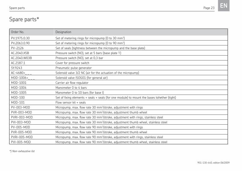
Spare parts*
Order No. Designation
PV.1975.0.30 Set of metering rings for micropump (0 to 30 mm3)PV.2063.0.90 Set of metering rings for micropump (0 to 90 mm3)PV-2126 Set of seals (tightness between the micropump and the base plate)AC.2040.X5B Pressure switch (NO), set at 5 bars (base plate ‘I’)AC.2040.W03B Pressure switch (NO), set at 0,3 barAC.2187.1 Cover for pressure switchSY.9243 Pneumatic pulse generatorAC-4680+_ _ _ Solenoid valve 3/2 NC (air for the actuation of the micropump)MOD-1006+_ _ _ Solenoid valve ISOG01 (for general air)MOD-1001 Carrier air flow regulatorMOD-1004 Manometer 0 to 4 barsMOD-1005 Manometer 0 to 10 bars (for base I)MOD-100 Set of fixing elements + seals + seals (for one module) to mount the bases tohether (tight)MOD-101 Flow sensor kit + sealsPV-003-MOD Micropump, max. flow rate 30 mm3/stroke, adjustment with ringsPVR-003-MOD Micropump, max. flow rate 30 mm3/stroke, adjustment thumb wheelPVRI-003-MOD Micropump, max. flow rate 30 mm3/stroke, adjustment with rings, stainless steelPVI-003-MOD Micropump, max. flow rate 30 mm3/stroke, adjustment thumb wheel, stainless steelPV-005-MOD Micropump, max. flow rate 90 mm3/stroke, adjustment with ringsPVR-005-MOD Micropump, max. flow rate 90 mm3/stroke, adjustment thumb wheelPVRI-005-MOD Micropump, max. flow rate 90 mm3/stroke, adjustment with rings, stainless steelPVI-005-MOD Micropump, max. flow rate 90 mm3/stroke, adjustment thumb wheel, stainless steel
*) Non-exhaustive list

EN Page 24
951-130-440, edition 06/2009
acing out of service
Temporary standstill
Comply with the instructions from the chapter Transport and Storage if the VTEC unit is to be at a standstill for a longer period of time.
Final standstill
If you want to bring the VTEC unit to a perma-nent standstill, please comply with the legal stipulations for disposal of grease containing components.
The system can also be taken back by SKF for disposal if the costs are covered.
Placing out of service

ENPage 25
951-130-440, edition 06/2009
Technical data
echnical data
VTEC systemNumber of modules . . . . . . . . . . . . . . . . . . . . . . . . . . . . . . . . . . . . . . . . . 1 to 8Min. air inlet . . . . . . . . . . . . . . . . . . . . . . . . . . . . . . . . . . . . . . . . . . . 800 Nl/min Dry and filtered air (5 μm)Air inlet pressure . . . . . . . . . . . . . . . . . . . . . . . . . . . . . . . . . . . . . . . 5 to 8 barsMicropump flow rateSmall flow:
Setting with metering ring . . . . . . . . . . . 3, 5, 10, 15, 20 and 30 mm3/strokeSetting with thumb wheel . . . . . . . . . . . . . . . . . . . . . . . . . 7 to 30 mm3/stroke
Large flow: Setting with metering ring . . . . . . . . . . . . . . . 30, 45, 60 and 90 mm3/strokeSetting with thumb wheel . . . . . . . . . . . . . . . . . . . . . . . . 30 to 90 mm3/stroke
Max. pump working frequency . . . . . . . . . . . . . . . . . . . . . . . . . . . . . . 3 strokes/sLubricant . . . . . . . . . . . . . . . . . . . . . . . . . . . . . . . . . . . mineral or synthetic oils ecological oilEffective viscosity . . . . . . . . . . . . . . . . . . . . . . . . . . . . . . . . . . 10 to 400 mm²/sService temperature . . . . . . . . . . . . . . . . . . . . . . . . . . . . . . . . . . . . 10 to 50 °CFixing rail . . . . . . . . . . . . . . . . . . . . . . . . . . . . . . . . . . . EN 50035 or EN 50022
General air solenoid valveDelivery rate (at 6 bars) . . . . . . . . . . . . . . . . . . . . . . . . . . . . . . . . . . 950 Nl/min Power supply . . . . . . . . . . . . . . . . . . . . . . . . . 115 V – 50/60 Hz – 2 VA (1,5 W) 230 V – 50/60 Hz – 2 VA (1,5 W) 24 V DC – 1,6 WProtection . . . . . . . . . . . . . . . . . . . . . . . . . . . . . . . . . . . . . . . . . . . . . . . . . . IP 65
Air solenoid valve (pump control)Delivery rate (at 6 bars) . . . . . . . . . . . . . . . . . . . . . . . . . . . . . . . . . . 150 Nl/min Power supply . . . . . . . . . . . . . . . . . . . . . . . . . . . . . . 115 V – 50/60 Hz – 2,5 W 230 V – 50/60 Hz – 2,5 W 24 V – 1 WProtection . . . . . . . . . . . . . . . . . . . . . . . . . . . . . . . . . . . . . . . . . . . . . . . . . . IP 65Mechanical life . . . . . . . . . . . . . . . . . . . . . . . . . . 1,5 × 10⁷ switching operations
Pneumatic pulse generatorDelivery rate (at 6 bars) . . . . . . . . . . . . . . . . . . . . . . . . . . . . . . . . . . 170 Nl/min Mechanical life . . . . . . . . . . . . . . . . . . . . . . . . . . . . 1 × 10⁷ switching operationsFrequency . . . . . . . . . . . . . . . . . . . . . . . . . . . . . . . . . . . . . . . . . . . 0,04 to 3 Hz
Pressure switchSwitching capacity . . . . . . . . . . . . . . . . . . . . . . . . . . . . . . . . . . . . . . . . . 100 VAProtection . . . . . . . . . . . . . . . . . . . . . . . . . . . . . . . . . . . . . . . . . . . . . . . . . . IP65Voltage max. . . . . . . . . . . . . . . . . . . . . . . . . . . . . . . . . . . . . . . . . . . . . . . . . 42 VMechanical life . . . . . . . . . . . . . . . . . . . . . . . . . . . . 1 × 10⁶ switching operations
Lubricant flow sensor GS304PSuitable for metered quantities from . . . . . . . . . . . . . . . . . . . . . 10 to 600 mm3 Max. Working frequency . . . . . . . . . . . . . . . . . . . . . . . . . . . . . . . . . 4 pulses/minLubricant viscosity . . . . . . . . . . . . . . . . . . . . . . . . . . . . . . . . . 10 to 400 mm²/sRated voltage . . . . . . . . . . . . . . . . . . . . . . . . . . . . . . . . . . . . . . . . . . . . . 24 V DC Load current IA . . . . . . . . . . . . . . . . . . . . . . . . . . . . . . . 500 mA max per output

EN Page 26
951-130-440, edition 06/2009
Services
NotesService
Please contact our sales offices or our interna-tional representatives if you have any ques-tions or problems.
You can find a list with current addresses on the Internet at:
www.skf.com/lubrication•


SKF Lubrication Systems France SASRue Robert Amy, B.P. 7013049404 SAUMUR cedex FRANCETel. +(33) 02 41 40 42 00 • Fax+(33) 02 41 40 42 42www.skf.com/lubrication 951-130-440-EN Edition 06/2009