Embed Size (px)
Citation preview
1
VSWR and Antenna Tuners
RF Mismatch
VSWR
Return Loss
Reflection CoefficientAntenna Tuners
Manual
Automatic
By Jack Tiley AD7FO
2
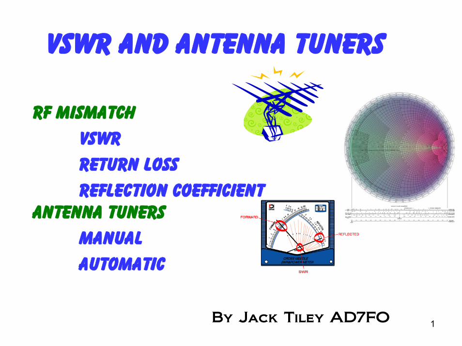
• In coaxial or open-wire line, current flowing in each of the two conductors travel in opposite directions.
• If the physical spacing between the two parallel conductors in an open-wire line is small in terms of wavelength, the phase difference between the currents will be very close to 180°.
• If the two currents also have equal amplitudes, the field generated by each conductor will cancel that generated by the other, and the line will not radiate energy, even if it is many wavelengths long.
VSWR and Antenna Tuners
3
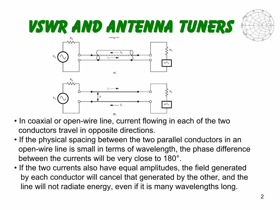
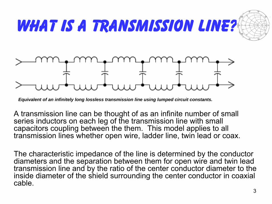
A transmission line can be thought of as an infinite number of small series inductors on each leg of the transmission line with smallcapacitors coupling between the them. This model applies to alltransmission lines whether open wire, ladder line, twin lead or coax.
The characteristic impedance of the line is determined by the conductor diameters and the separation between them for open wire and twin lead transmission line and by the ratio of the center conductor diameter to the inside diameter of the shield surrounding the center conductor in coaxial cable.
What is a Transmission line?
Equivalent of an infinitely long lossless transmission line using lumped circuit constants.
4
Importance of VSWR
• It is important that your transmitter operates into a matching impedance to prevent damage
• A common misconception is that your VSWR must be 1:1. A 1:1 VSWR implies a perfect match between the transmitter and the antenna system.
• It is possible to have a low VSWR and an antenna system that is a poor radiator.
• A dummy load may have a 1:1 match but it will not radiate your signal.
5
Many Ways To Express AnImpedance Mismatch
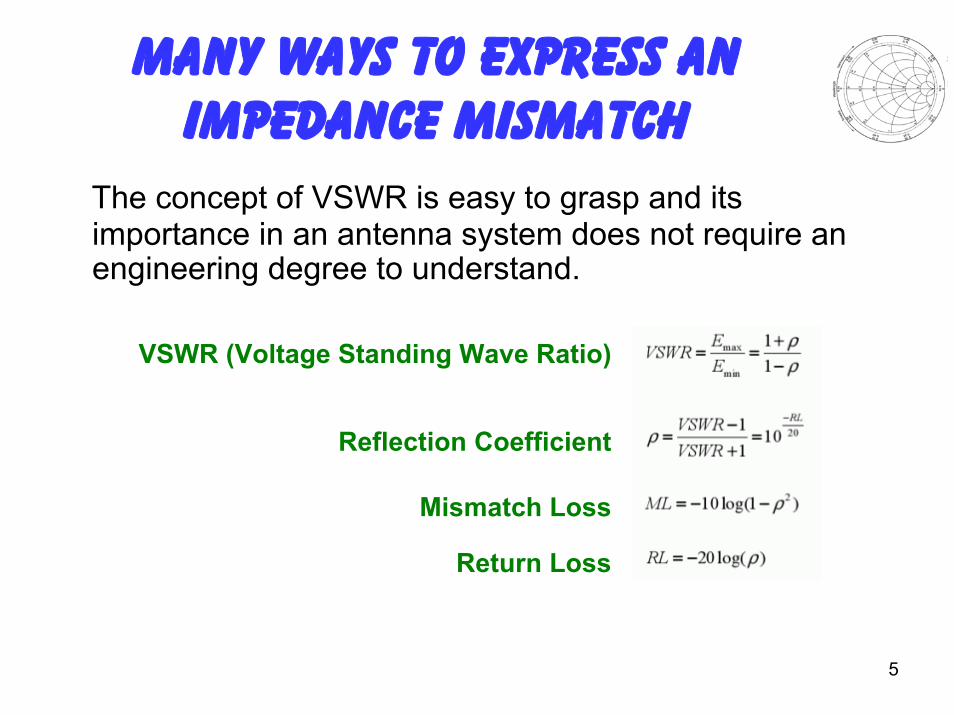
VSWR (Voltage Standing Wave Ratio)
Reflection Coefficient
Mismatch Loss
Return Loss
The concept of VSWR is easy to grasp and its importance in an antenna system does not require an engineering degree to understand.
6
VSWR Example calculation
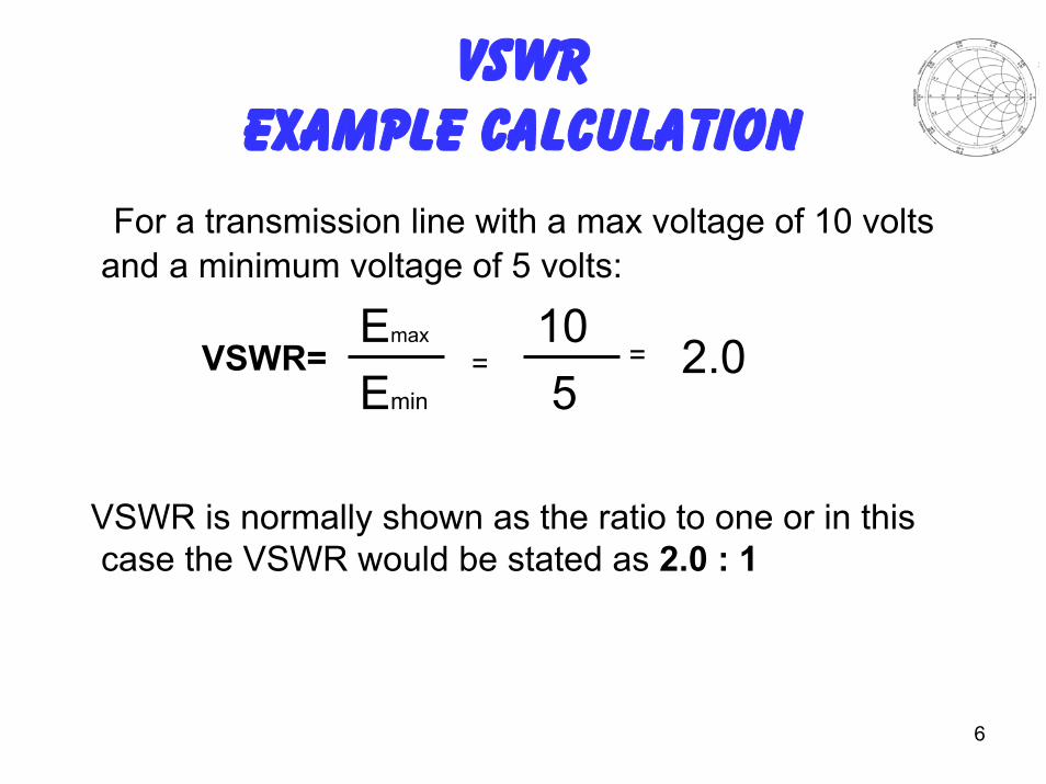
For a transmission line with a max voltage of 10 volts and a minimum voltage of 5 volts:
Emax 10Emin 5
VSWR is normally shown as the ratio to one or in this case the VSWR would be stated as 2.0 : 1
VSWR= = = 2.0
7
Reflection coefficient Example calculation
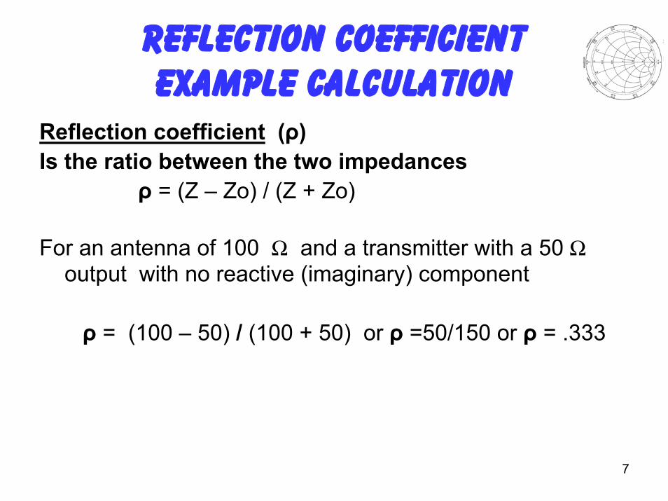
Reflection coefficient (ρ)Is the ratio between the two impedances
ρ = (Z – Zo) / (Z + Zo)
For an antenna of 100 Š and a transmitter with a 50 Šoutput with no reactive (imaginary) component
ρ = (100 – 50) / (100 + 50) or ρ =50/150 or ρ = .333
8
VSWR Using Reflectioncoefficient Example
For an antenna of 100 Š and a transmitter with a 50 Šoutput (with no reactive or imaginary component)
VSWR= (1+ p)/ (1- p)
VSWR= (1+.333) / (1-.333) or VSWR= 1.333/.667 or
VSWR= 2.00
VSWR is normally shown as the ratio to one or in this case the VSWR would be stated as 2.0 : 1
9
Return Loss Example
Return Loss Return Loss (RL) is the ratio of the forward power to the reflected power in dB. A perfect load would have infinite return loss meaning that no power would be returned to the source (transmitter). A short or open would have zero dB return loss meaning that there is zero db loss in the reflected signal relative to the forward signal meaning it was totally reflected back to the source (transmitter).
RL= -10 (log10 (ρ²))
For an antenna of 100 Š and a transmitter with a 50 Š output (with no reactive or imaginary component)
RL=-10 (log10 (.333²)) RL = -10 (log10 (.1109)) RL = -9.55dB
10
Mismatch Error Loss Example
For an antenna with a reflection coefficient of .333 (or a VSWR of 2.0 : 1)
Mismatch Loss = -10 (log (1- ρ²))Mismatch Loss = -10 (log (1- (.333)²))Mismatch Loss = -10 (log (1- .1109))Mismatch Loss = -10 (log (.8891))Mismatch Return Loss = -10 (-.0510)Mismatch Return Loss = .510 dB
11
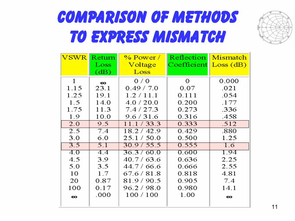
Comparison of Methods To Express Mismatch
12
The Ideal Situation
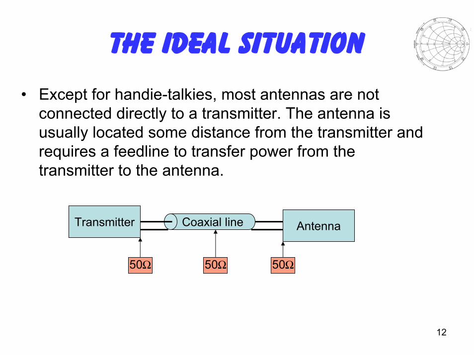
• Except for handie-talkies, most antennas are not connected directly to a transmitter. The antenna is usually located some distance from the transmitter and requires a feedline to transfer power from the transmitter to the antenna.
Transmitter Coaxial line Antenna
50Š 50Š 50Š
13
The Real World• In order to transfer maximum power into a load (Antenna
and Transmission line) impedance must match the generator (transmitter) impedance. Any difference, or mismatching, of these impedances would result in less than maximum power transfer to the antenna.
• In the case where the VSWR is 1:1 and the voltage and current will be constant over the whole length of the feedline. Any deviation from this situation will cause a "standing wave" of voltage and current to exist on the transmission line.
14
What Causes Standing Waves
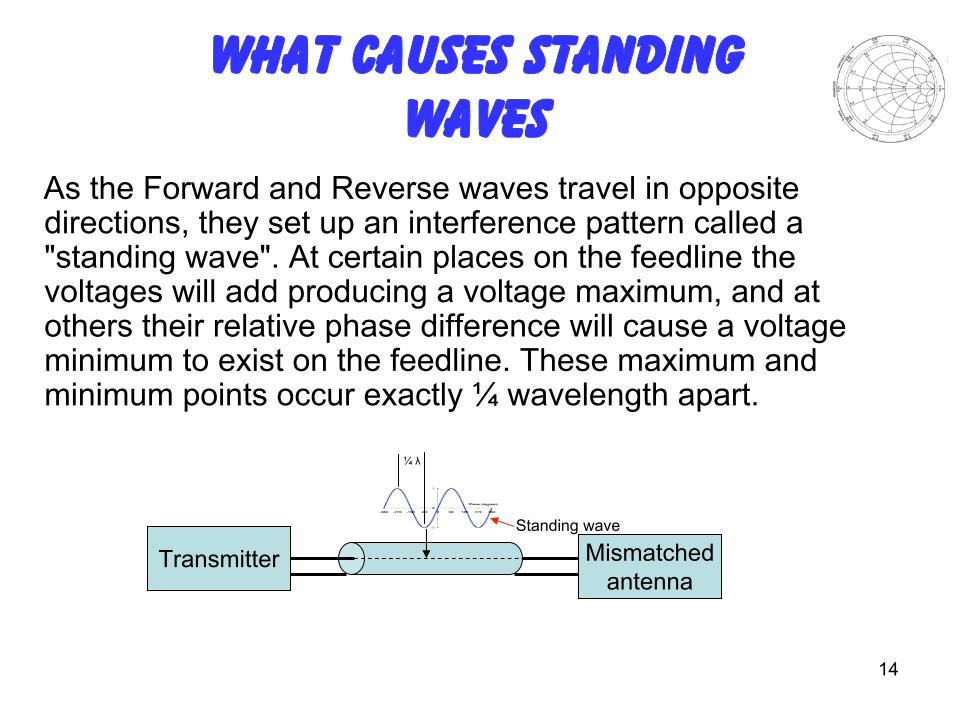
As the Forward and Reverse waves travel in opposite directions, they set up an interference pattern called a "standing wave". At certain places on the feedline the voltages will add producing a voltage maximum, and at others their relative phase difference will cause a voltage minimum to exist on the feedline. These maximum and minimum points occur exactly ¼ wavelength apart.
Transmitter Mismatchedantenna
Standing wave
¼ λ
15
What Causes Standing Waves
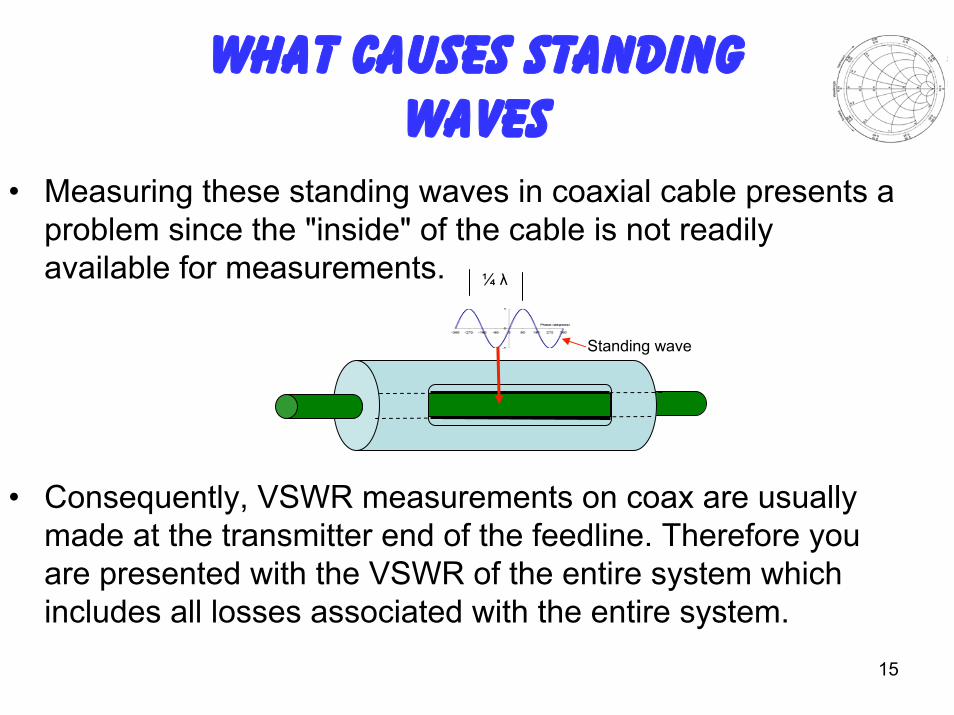
• Measuring these standing waves in coaxial cable presents a problem since the "inside" of the cable is not readily available for measurements.
• Consequently, VSWR measurements on coax are usually made at the transmitter end of the feedline. Therefore you are presented with the VSWR of the entire system which includes all losses associated with the entire system.
Standing wave
¼ λ
16
The Open or Shorted Line
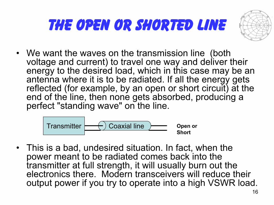
• We want the waves on the transmission line (both voltage and current) to travel one way and deliver their energy to the desired load, which in this case may be an antenna where it is to be radiated. If all the energy gets reflected (for example, by an open or short circuit) at the end of the line, then none gets absorbed, producing a perfect "standing wave" on the line.
• This is a bad, undesired situation. In fact, when the power meant to be radiated comes back into the transmitter at full strength, it will usually burn out the electronics there. Modern transceivers will reduce their output power if you try to operate into a high VSWR load.
Transmitter Coaxial line Open or Short
17
Long Feedlines Mask The load VSWR
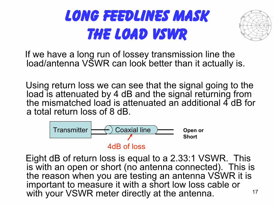
If we have a long run of lossey transmission line the load/antenna VSWR can look better than it actually is.
Using return loss we can see that the signal going to the load is attenuated by 4 dB and the signal returning from the mismatched load is attenuated an additional 4 dB for a total return loss of 8 dB.
Eight dB of return loss is equal to a 2.33:1 VSWR. This is with an open or short (no antenna connected). This is the reason when you are testing an antenna VSWR it is important to measure it with a short low loss cable or with your VSWR meter directly at the antenna.
Transmitter Coaxial line Open or Short
4dB of loss
18
Standing Waves
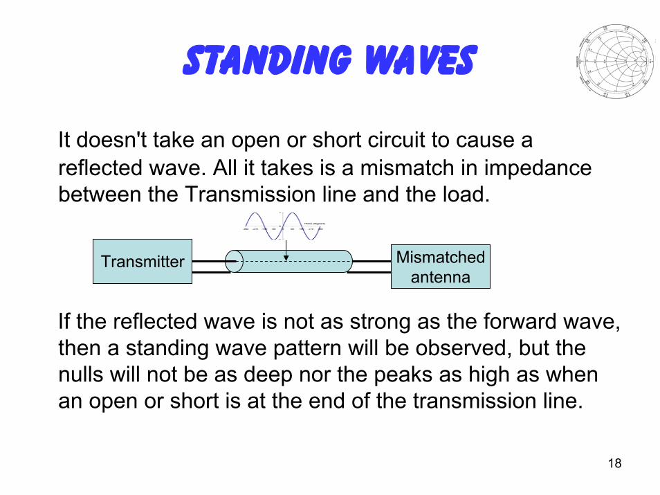
It doesn't take an open or short circuit to cause a reflected wave. All it takes is a mismatch in impedance between the Transmission line and the load.
If the reflected wave is not as strong as the forward wave, then a standing wave pattern will be observed, but the nulls will not be as deep nor the peaks as high as when an open or short is at the end of the transmission line.
Transmitter Mismatchedantenna
19
It Is Not That Simple
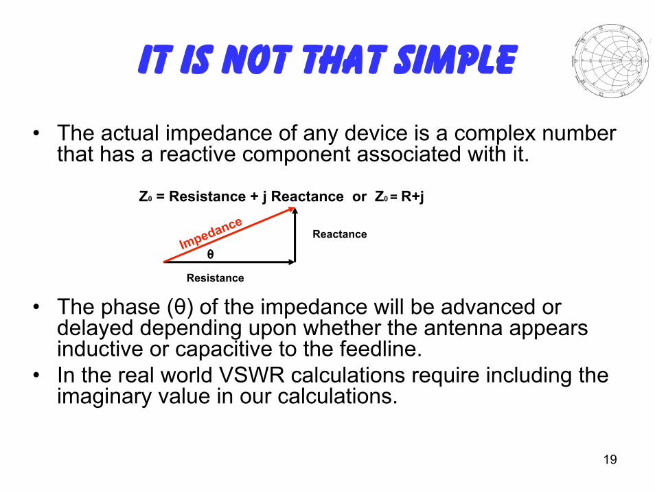
• The actual impedance of any device is a complex number that has a reactive component associated with it.
Z0 = Resistance + j Reactance or Z0 = R+j
• The phase (θ) of the impedance will be advanced or delayed depending upon whether the antenna appears inductive or capacitive to the feedline.
• In the real world VSWR calculations require including the imaginary value in our calculations.
Reactance
Resistance
θImpedance
20
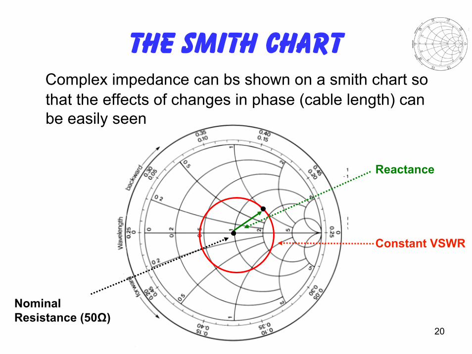
The Smith ChartComplex impedance can bs shown on a smith chart so that the effects of changes in phase (cable length) can be easily seen
Reactance
Constant VSWR
Nominal Resistance (50Ω)
21
The Full Reflection Coefficient Equation
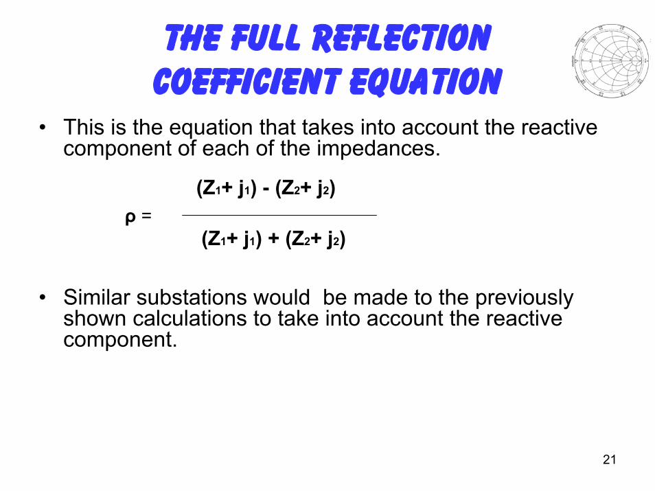
• This is the equation that takes into account the reactive component of each of the impedances.
ρ =
• Similar substations would be made to the previously shown calculations to take into account the reactive component.
(Z1+ j1) - (Z2+ j2)
(Z1+ j1) + (Z2+ j2)
22
Measuring VSWR
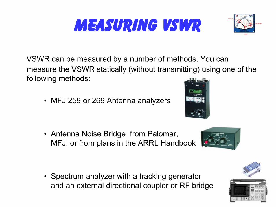
VSWR can be measured by a number of methods. You can measure the VSWR statically (without transmitting) using one of the following methods:
• MFJ 259 or 269 Antenna analyzers
• Antenna Noise Bridge from Palomar, MFJ, or from plans in the ARRL Handbook
• Spectrum analyzer with a tracking generator and an external directional coupler or RF bridge
23
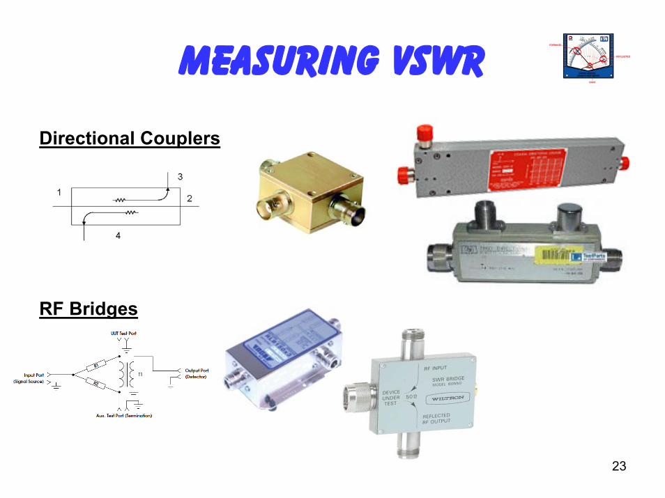
Measuring VSWR
Directional Couplers
RF Bridges
24
Measuring VSWR
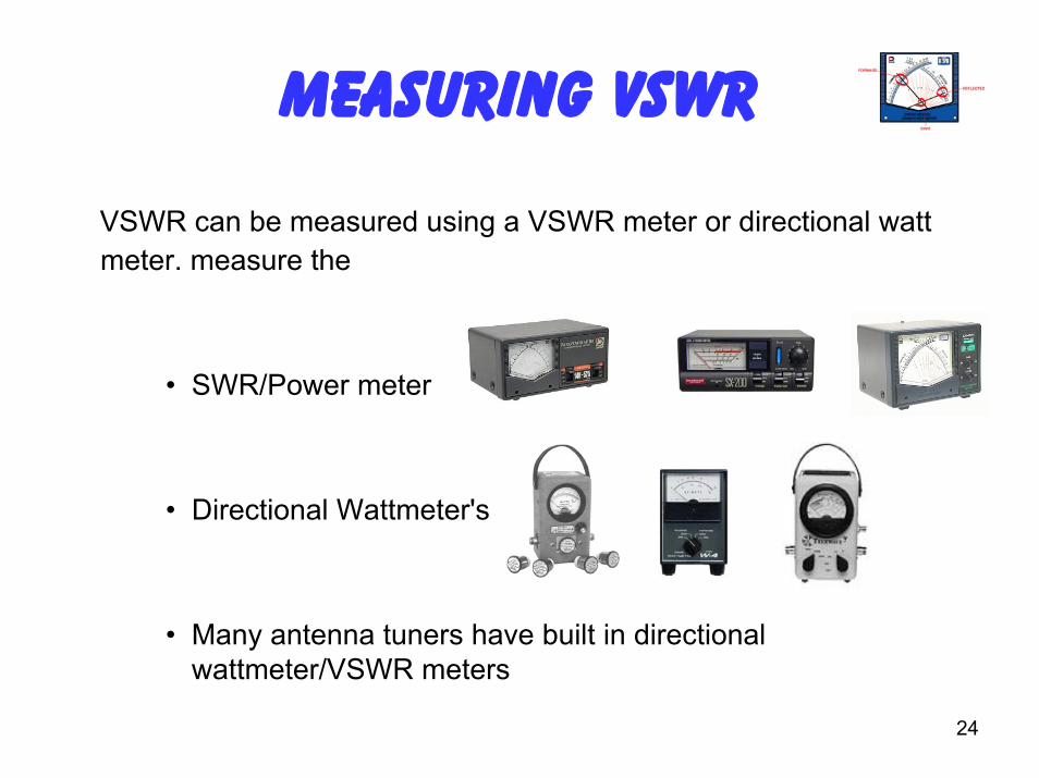
VSWR can be measured using a VSWR meter or directional watt meter. measure the
• SWR/Power meter
• Directional Wattmeter's
• Many antenna tuners have built in directional wattmeter/VSWR meters
25
Measuring VSWR
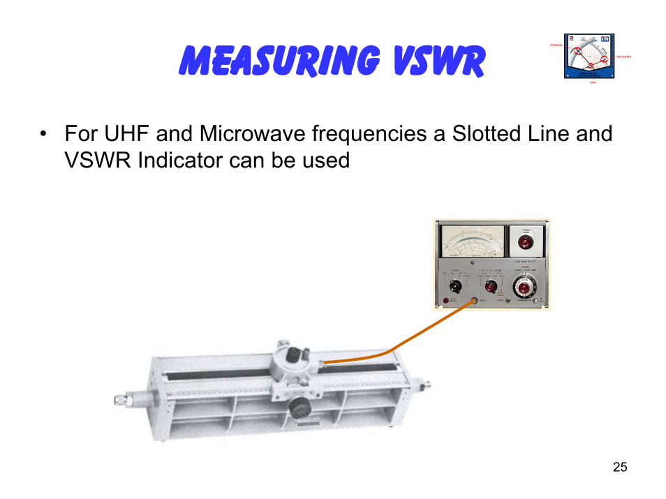
• For UHF and Microwave frequencies a Slotted Line and VSWR Indicator can be used
26
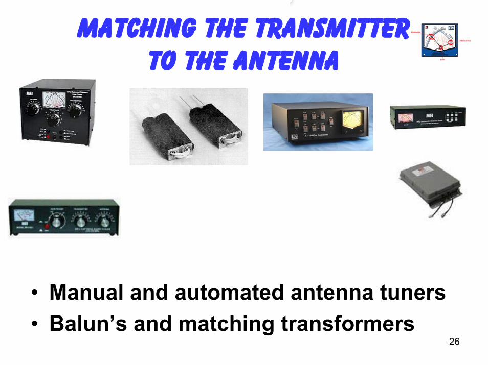
Matching The Transmitter To The Antenna
• Manual and automated antenna tuners • Balun’s and matching transformers
27
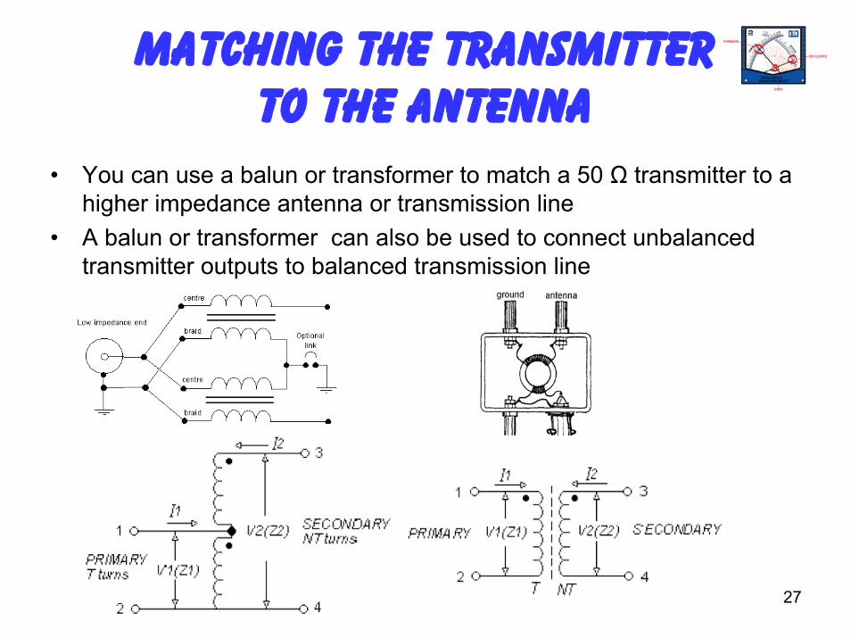
Matching The Transmitter To The Antenna
• You can use a balun or transformer to match a 50 Ω transmitter to a higher impedance antenna or transmission line
• A balun or transformer can also be used to connect unbalanced transmitter outputs to balanced transmission line
28
Antenna Tuners
• An antenna tuner, transmatch , doesn't really TUNE your antenna OR ANY PART OF IT!
• What an antenna tuner or transmatch does do, is transform the impedance at the antenna feed output at the radio to a value that your transceiver can handle, (typically 50 Ohms).
• When thinking about antenna tuners and SWR, it's important to remember that the tuner has no effect whatsoever on the SWR between itself and the antenna. It is the SWR between the transmitter and the tuner that is changed with the tuner controls.
29
Antenna Tuners
In layman's terms, all a tuner does is act as a kind of adjustable impedance transformer between the radio and the antenna. It takes whatever impedance the antenna system presents, up to the design limits of the tuner, and attempts to convert it back to 50 Ohms--or something reasonably close to that value for the transceiver. The transceiver will see a 50 Ohm impedance, and deliver it's maximum designed RF output.
30
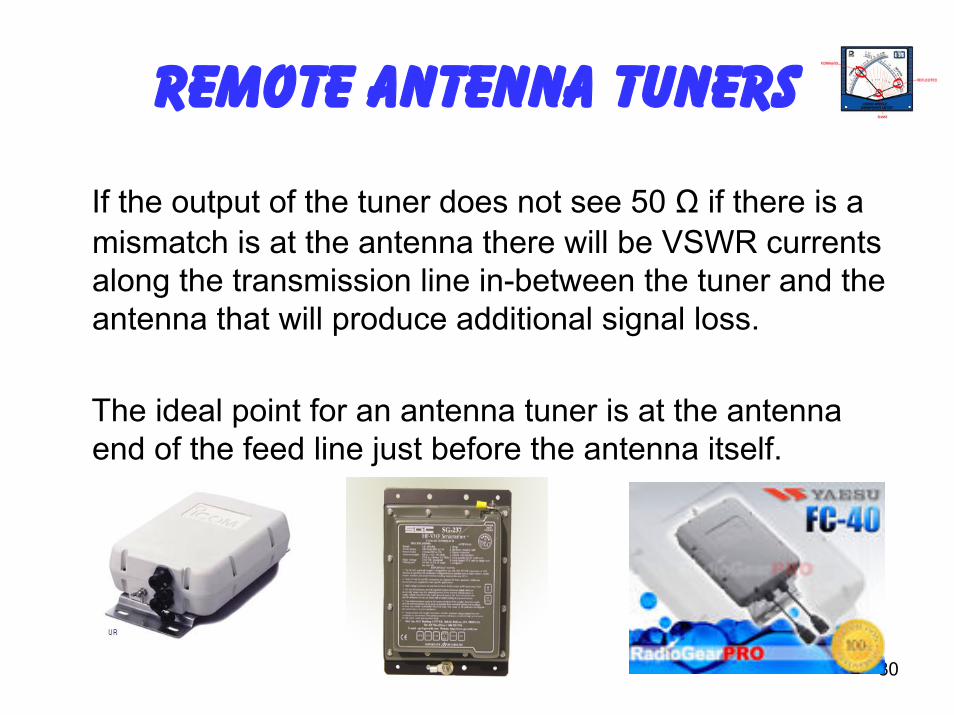
Remote Antenna Tuners
If the output of the tuner does not see 50 Ω if there is a mismatch is at the antenna there will be VSWR currents along the transmission line in-between the tuner and the antenna that will produce additional signal loss.
The ideal point for an antenna tuner is at the antenna end of the feed line just before the antenna itself.
31
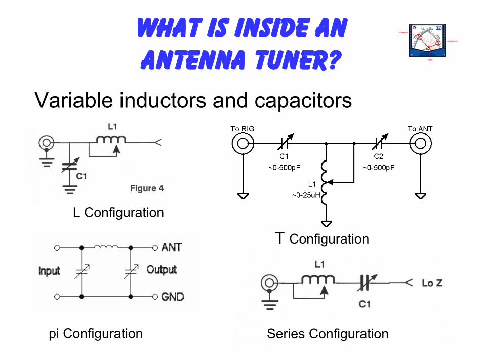
What Is Inside An Antenna Tuner?
Variable inductors and capacitors
L Configuration
Series Configuration
T Configuration
pi Configuration
32
Antenna Tuners are based upon lumped components as shown in the previous slide.
The website listed below has a detailed explanation of how an antenna tuner actually matches one complex impedance to another, including the equations for solving the components needed to accomplish the match.
http://en.wikipedia.org/wiki/Antenna_tuner
How does an Antenna Tuner work?
33
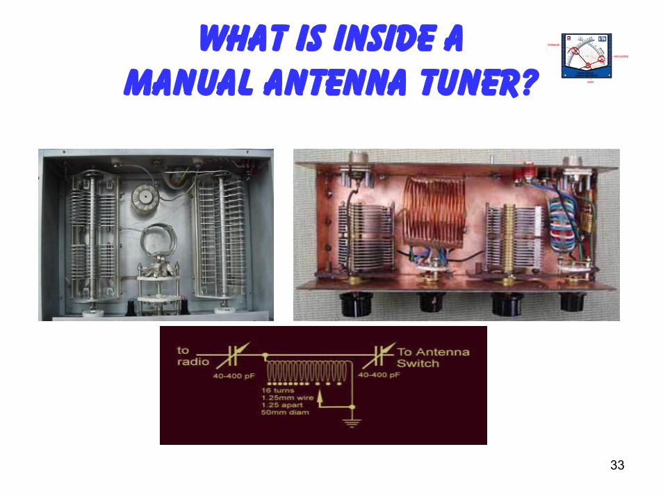
What Is Inside A Manual Antenna Tuner?
34
NOW LET'S LEARN TO Use the Antenna TUNER
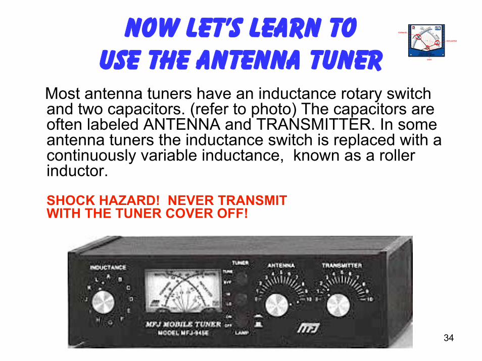
Most antenna tuners have an inductance rotary switch and two capacitors. (refer to photo) The capacitors are often labeled ANTENNA and TRANSMITTER. In some antenna tuners the inductance switch is replaced with a continuously variable inductance, known as a roller inductor.
SHOCK HAZARD! NEVER TRANSMIT WITH THE TUNER COVER OFF!
35
NOW LET'S LEARN TO Use the Antenna TUNER
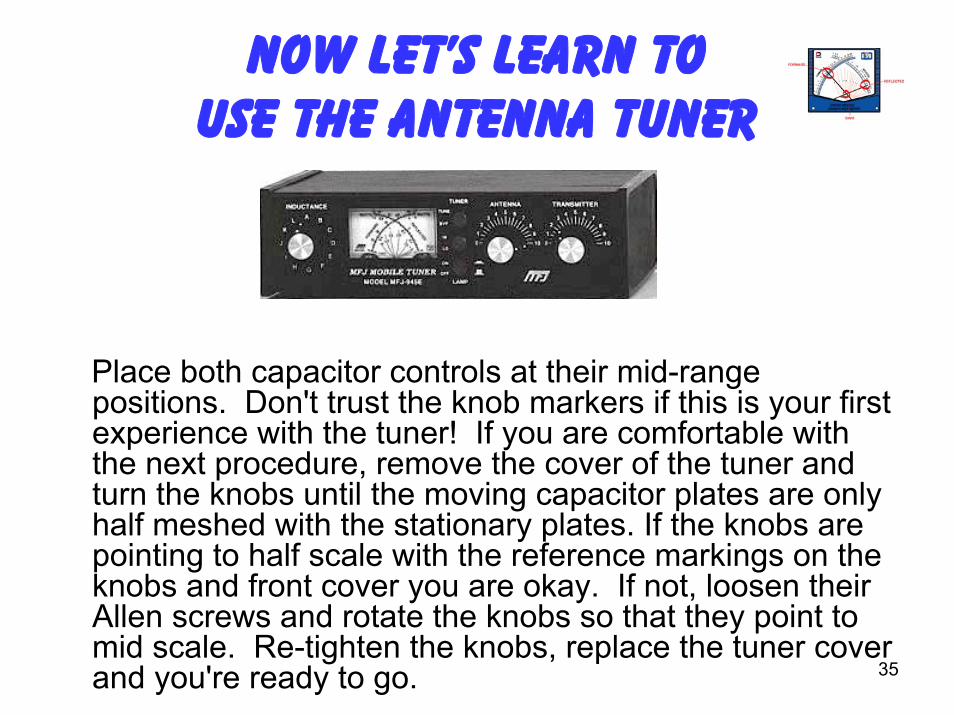
Place both capacitor controls at their mid-range positions. Don't trust the knob markers if this is your first experience with the tuner! If you are comfortable with the next procedure, remove the cover of the tuner and turn the knobs until the moving capacitor plates are only half meshed with the stationary plates. If the knobs are pointing to half scale with the reference markings on the knobs and front cover you are okay. If not, loosen their Allen screws and rotate the knobs so that they point to mid scale. Re-tighten the knobs, replace the tuner cover and you're ready to go.
36
Best Practice caution
• Play it safe and un-key before turning the inductor switch...un-key first....turn the switch...key up....repeat as needed until lowest SWR and maximum output. Be gentle to your radio; keep the key-down periods as short as possible. Depending on the impedance at the antenna input (and the overall design of the tuner) you may not be able to obtain a flat 1:1 SWR on all frequencies and bands. Any thing below a 2:1 or lower will work well.
• Also important to remember is that your SWR will change, go up, as you tune further away from the frequency you used to "trick" your radio! So re-check and re-tune as needed as you move around the band.
37
Using the Antenna Tuner
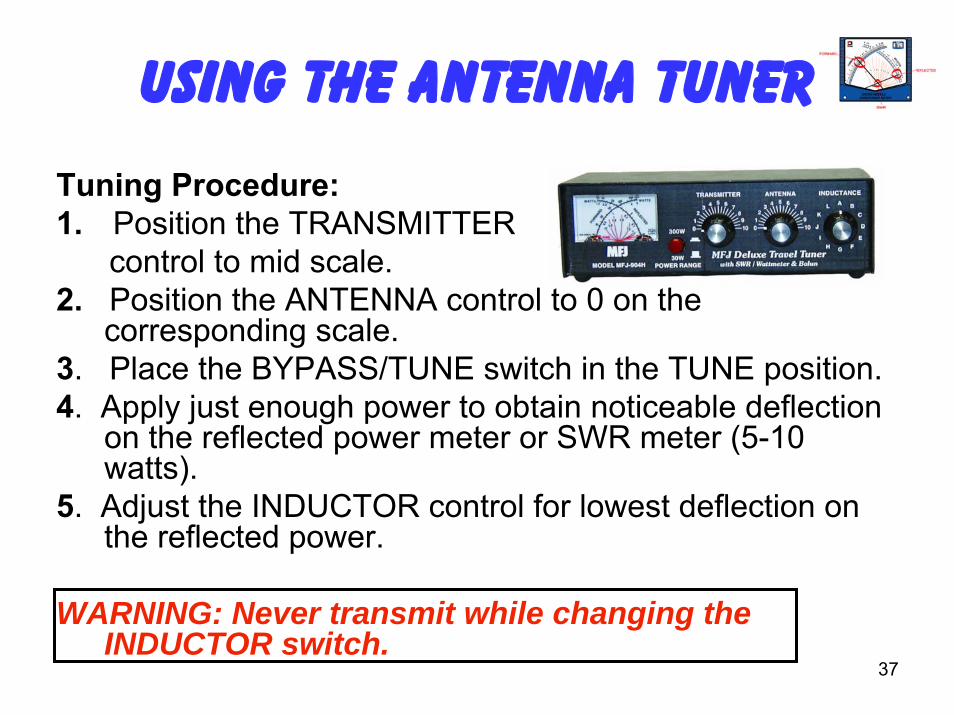
Tuning Procedure:1. Position the TRANSMITTER
control to mid scale.2. Position the ANTENNA control to 0 on the
corresponding scale.3. Place the BYPASS/TUNE switch in the TUNE position.4. Apply just enough power to obtain noticeable deflection
on the reflected power meter or SWR meter (5-10 watts).
5. Adjust the INDUCTOR control for lowest deflection on the reflected power.
WARNING: Never transmit while changing the INDUCTOR switch.
38
6. Carefully adjust the TRANSMITTER control for the lowest reflected power, then increase the ANTENNA control slightly and adjust the TRANSMITTER control for the lowest reflected power. Again, increase the ANTENNA control slightly and adjust the TRANSMITTER control for lowest reflected power. Repeat this process for lowest reflected power.Note: These controls interact. Go back and forth between these adjustments as many times as required until the lowest reflected power (best SWR) is obtained.
Using the Antenna Tuner
39
7. After the lowest reflected power (or SWR) is obtained in step 6, use the INDUCTOR switch to reduce the inductance one switch position (L is the lowest inductance setting and A is the highest inductance setting). Adjust the TRANSMITTER and ANTENNA controls for the lowest SWR. (A is the highest inductance setting). Tune for lowest SWR.
Note: Always use as little inductance as possible.8. After a low SWR is obtained, the transmitter power may
be increased to the maximum allowable for your Antenna Tuner
9. Note the antenna tuner settings so you can return to them the next time you operate on that frequency.
Using the Antenna Tuner
40
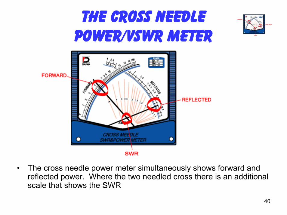
The Cross Needle Power/VSWR Meter
• The cross needle power meter simultaneously shows forward and reflected power. Where the two needled cross there is an additional scale that shows the SWR
41
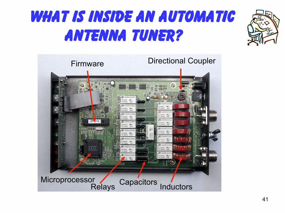
What is inside an Automatic Antenna Tuner?
Directional Coupler
InductorsMicroprocessor CapacitorsRelays
Firmware
42
Now that you have seen what it takes to set up a manual antenna tuner you will appreciate the automatic antenna tuner. An automatic antenna tuner automatically goes through the same process you would do with a manual antenna tuner. A microprocessor monitors the antenna VSWR and uses relays to switch in inductance and capacitance until a satisfactory VSWR is obtained. Typically less than 5 seconds
Many of today's automatic antenna tuners will store the frequency and settings so when you come back to that frequency the tuner can quickly go back to the previous settings making tune up very fast (1-2 seconds)
Automatic Tuners
43
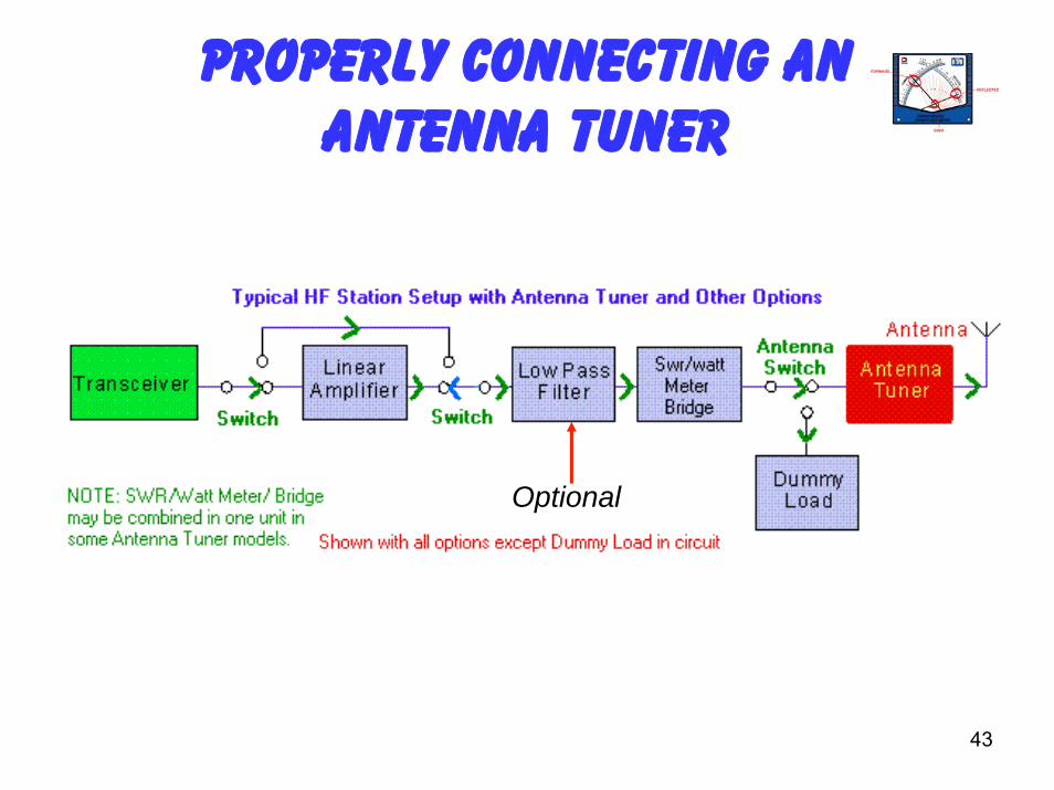
Properly Connecting An Antenna Tuner
Optional
44
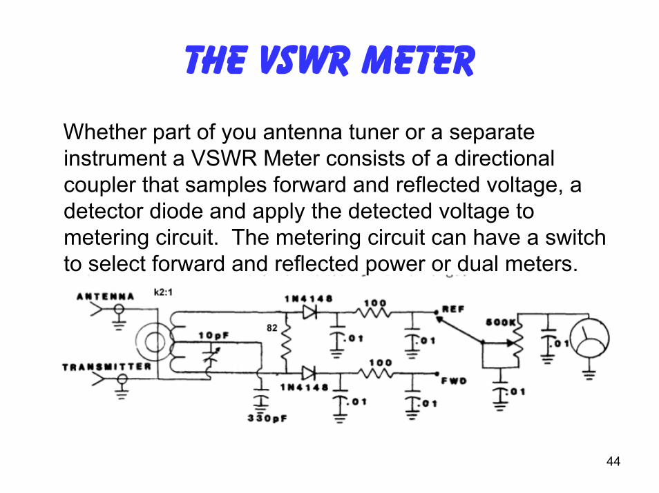
The VSWR Meter
Whether part of you antenna tuner or a separate instrument a VSWR Meter consists of a directional coupler that samples forward and reflected voltage, a detector diode and apply the detected voltage to metering circuit. The metering circuit can have a switch to select forward and reflected power or dual meters.
45
Any Questions?
Antenna tuner reference siteshttp://www.hamuniverse.com/tuner.html
http://www.hamuniverse.com/wc7iswr.html

46
Conversion Chart