Embed Size (px)
Citation preview
High-speed ADC techniques- overview and scaling issues -
Vladimir Stojanovic
06/14/2001 Vladimir Stojanovic 2
Outline
• High-Speed ADC applications
• Basic ADC performance metrics
• Architectures – overview
• ADCs in 90s
• Limiting factors
• Conclusion
06/14/2001 Vladimir Stojanovic 3
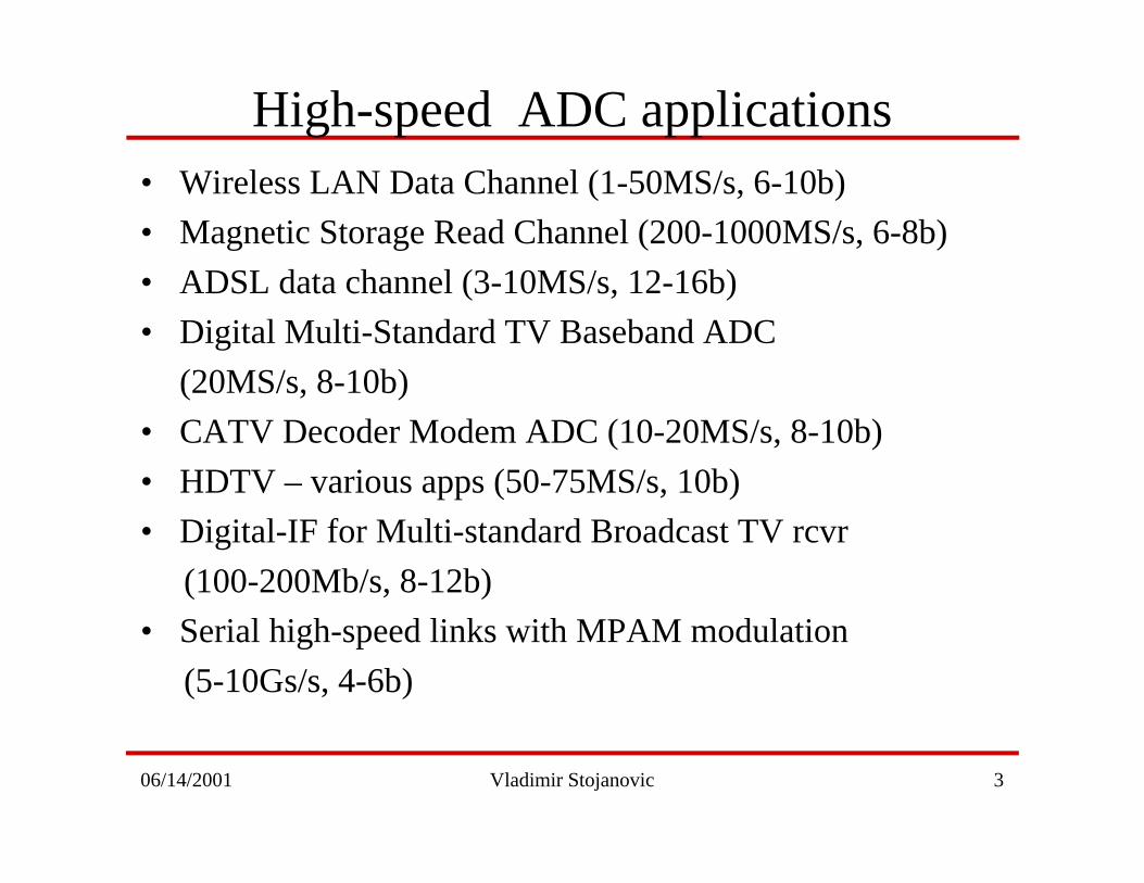
High-speed ADC applications• Wireless LAN Data Channel (1-50MS/s, 6-10b)
• Magnetic Storage Read Channel (200-1000MS/s, 6-8b)
• ADSL data channel (3-10MS/s, 12-16b)
• Digital Multi-Standard TV Baseband ADC
(20MS/s, 8-10b)
• CATV Decoder Modem ADC (10-20MS/s, 8-10b)
• HDTV – various apps (50-75MS/s, 10b)
• Digital-IF for Multi-standard Broadcast TV rcvr
(100-200Mb/s, 8-12b)
• Serial high-speed links with MPAM modulation
(5-10Gs/s, 4-6b)
06/14/2001 Vladimir Stojanovic 4
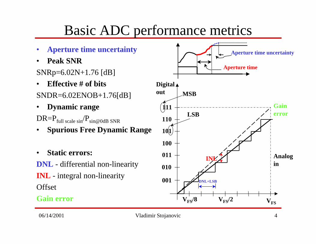
Basic ADC performance metrics• Aperture time uncertainty• Peak SNRSNRp=6.02N+1.76 [dB]
• Effective # of bitsSNDR=6.02ENOB+1.76[dB]
• Dynamic rangeDR=Pfull scale sin/Psin@0dB SNR
• Spurious Free Dynamic Range
• Static errors:DNL - differential non-linearity
INL - integral non-linearity
Offset
Gain error
Analog in
DNL+LSB
INL
Gain error
001
010
011
100
101
110
111
Digital out
VFSVFS/2VFS/8
MSB
LSB
Aperture time
Aperture time uncertainty
06/14/2001 Vladimir Stojanovic 5
Architectures
• Flash– Interpolation
– Averaging
• Folding– Folding and Interpolation
• Two-step– Subranging
– Flash
• Pipeline– Per-stage calibration
06/14/2001 Vladimir Stojanovic 6
pre-amplifier
comparator
1
1
1
1
0
0
0
0
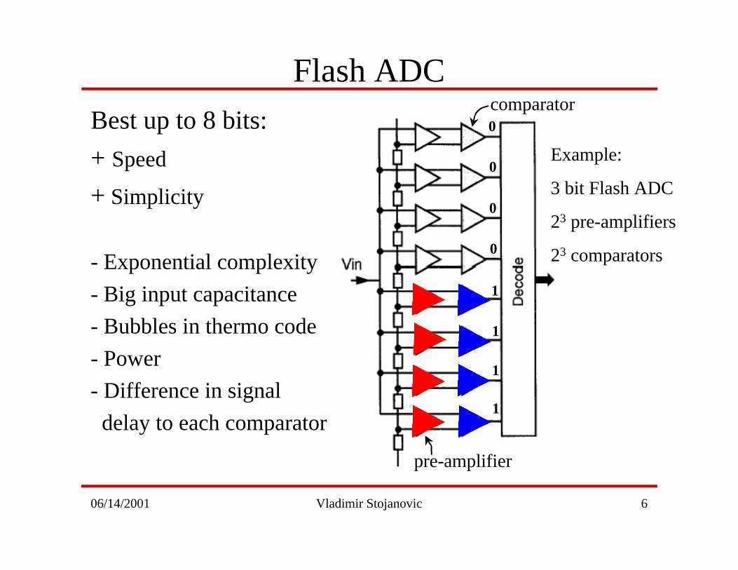
Flash ADC
Best up to 8 bits:
+ Speed
+ Simplicity
- Exponential complexity
- Big input capacitance
- Bubbles in thermo code
- Power
- Difference in signal
delay to each comparator
Example:
3 bit Flash ADC
23 pre-amplifiers
23 comparators
06/14/2001 Vladimir Stojanovic 7
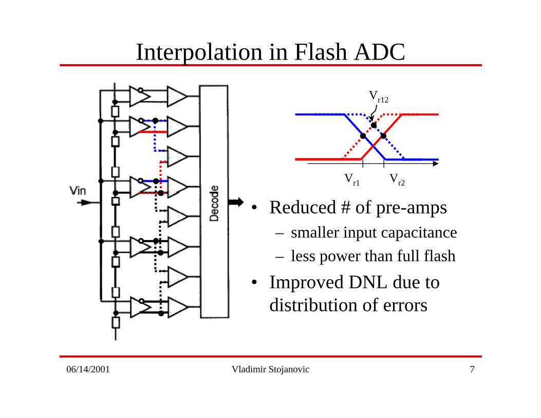
Interpolation in Flash ADC
Vr1 Vr2
Vr12
• Reduced # of pre-amps– smaller input capacitance
– less power than full flash
• Improved DNL due todistribution of errors
06/14/2001 Vladimir Stojanovic 8
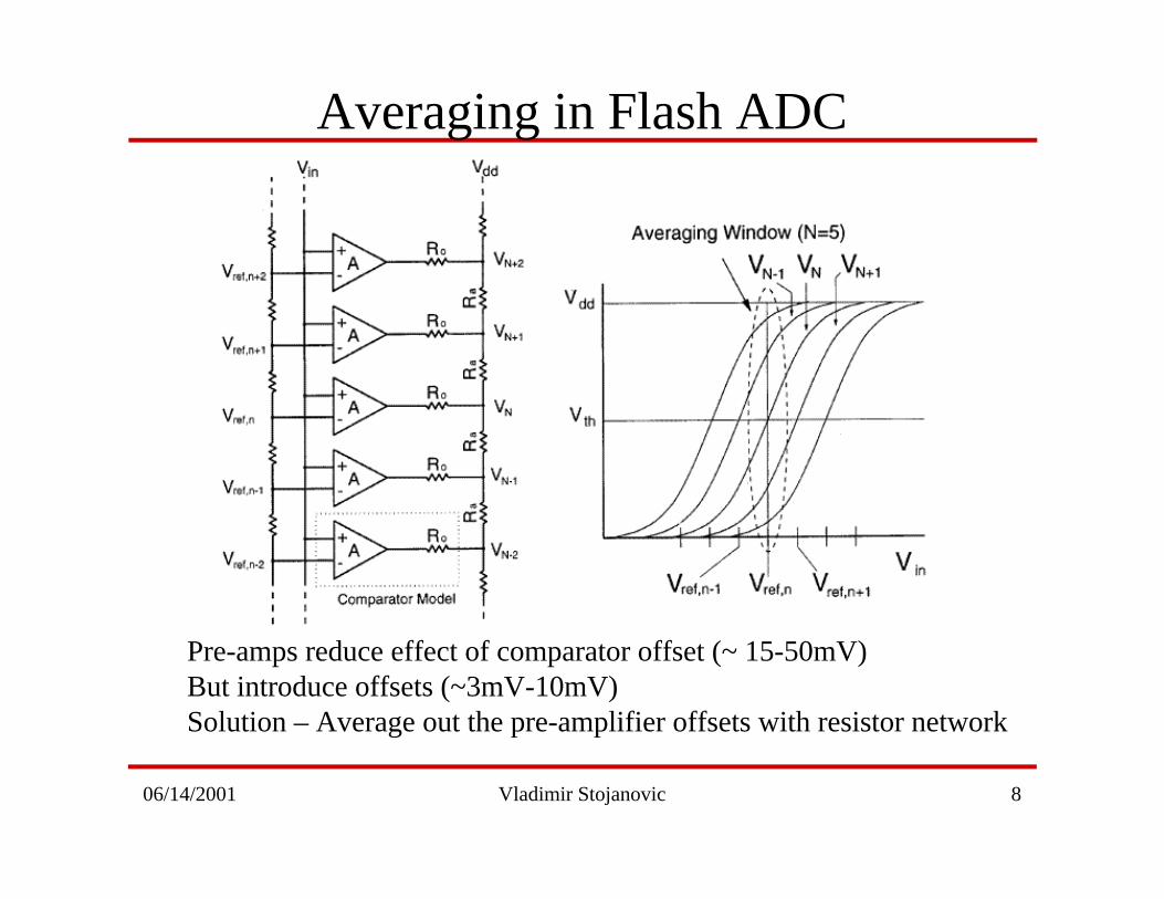
Averaging in Flash ADC
Pre-amps reduce effect of comparator offset (~ 15-50mV)But introduce offsets (~3mV-10mV)Solution – Average out the pre-amplifier offsets with resistor network
06/14/2001 Vladimir Stojanovic 9
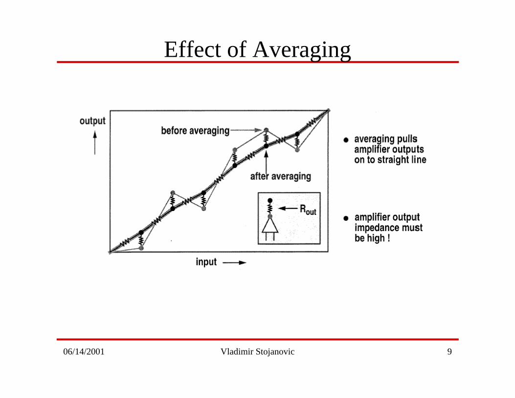
Effect of Averaging
06/14/2001 Vladimir Stojanovic 10
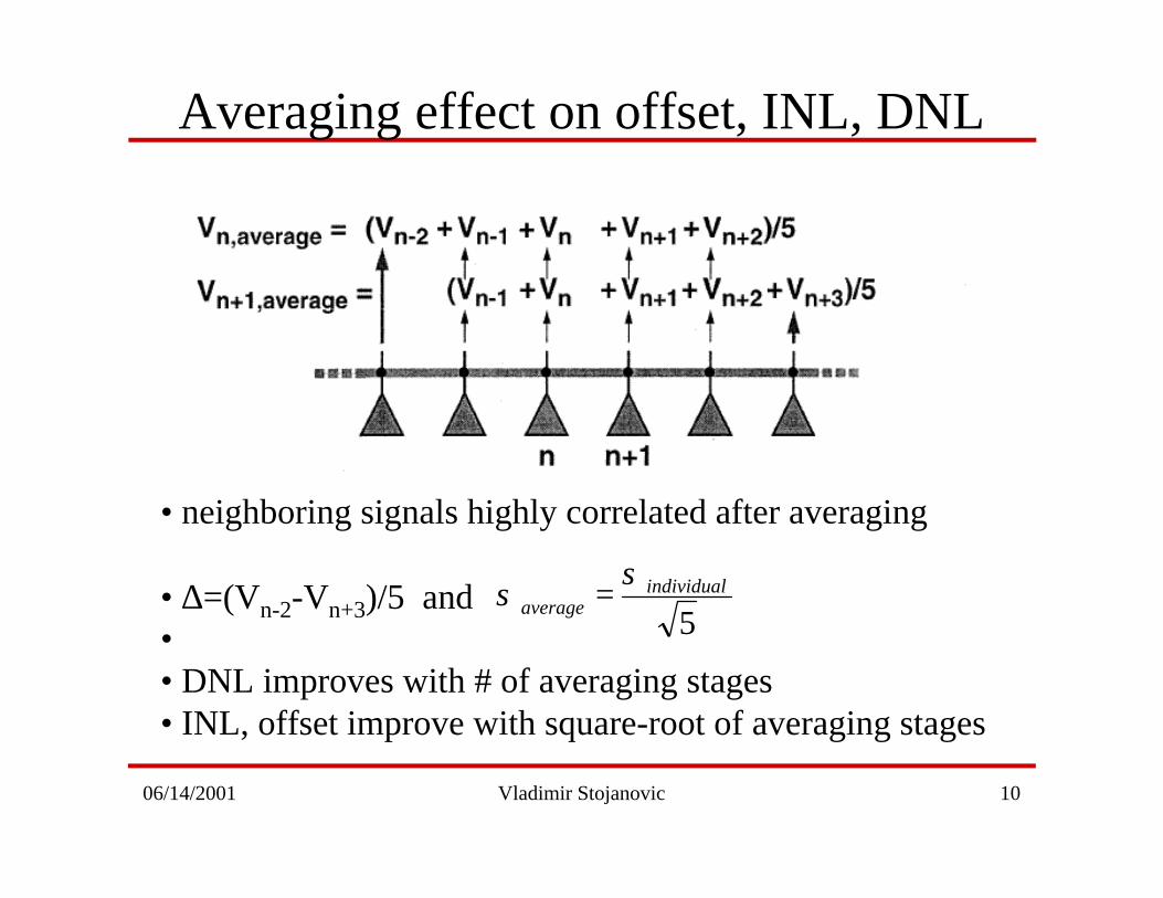
Averaging effect on offset, INL, DNL
• neighboring signals highly correlated after averaging
• ∆=(Vn-2-Vn+3)/5 and•• DNL improves with # of averaging stages• INL, offset improve with square-root of averaging stages
5individual
average
σσ =
06/14/2001 Vladimir Stojanovic 11
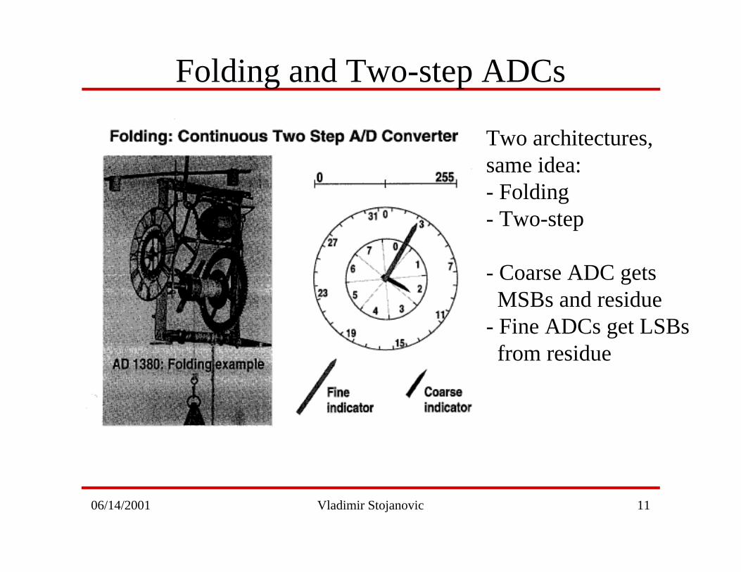
Folding and Two-step ADCs
Two architectures, same idea:- Folding- Two-step
- Coarse ADC gets MSBs and residue- Fine ADCs get LSBs from residue
06/14/2001 Vladimir Stojanovic 12
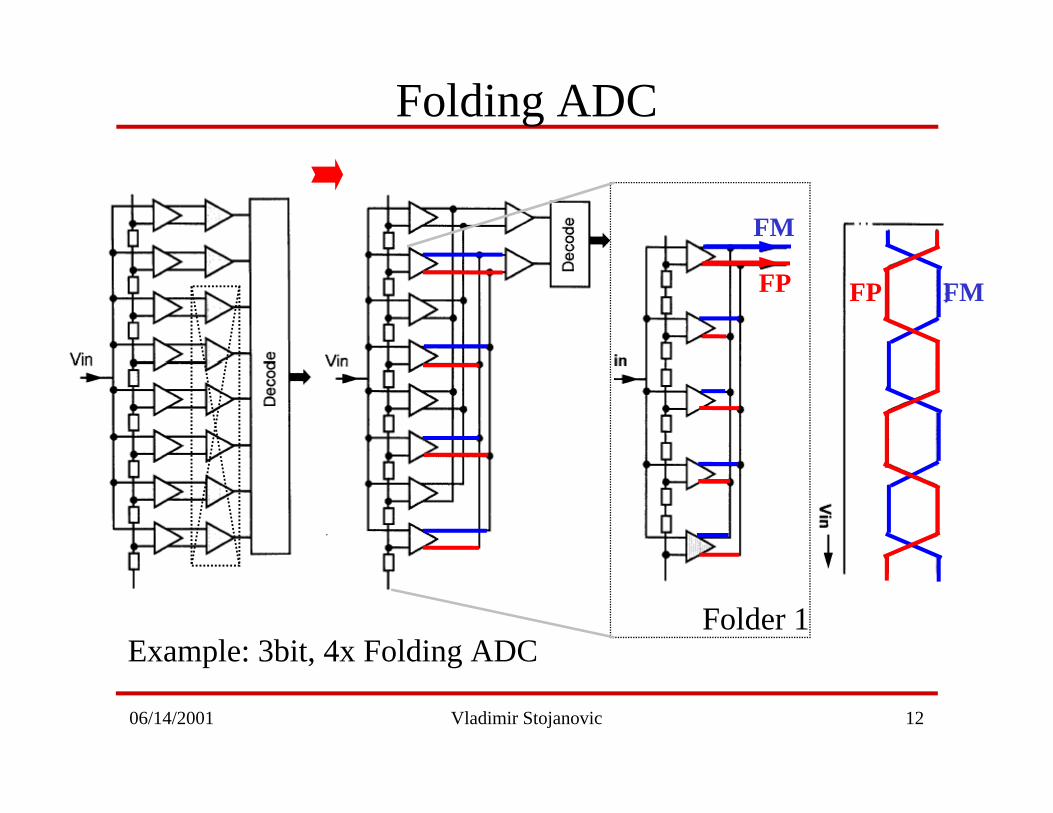
Folding ADC
FM
FP
Example: 3bit, 4x Folding ADCFolder 1
FMFP
06/14/2001 Vladimir Stojanovic 13
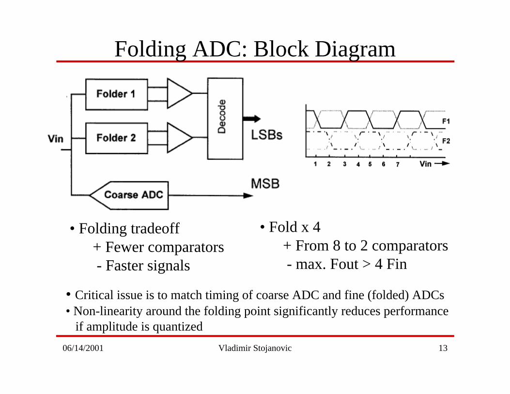
Folding ADC: Block Diagram
• Folding tradeoff+ Fewer comparators - Faster signals
• Fold x 4+ From 8 to 2 comparators - max. Fout > 4 Fin
• Critical issue is to match timing of coarse ADC and fine (folded) ADCs• Non-linearity around the folding point significantly reduces performance if amplitude is quantized
06/14/2001 Vladimir Stojanovic 14
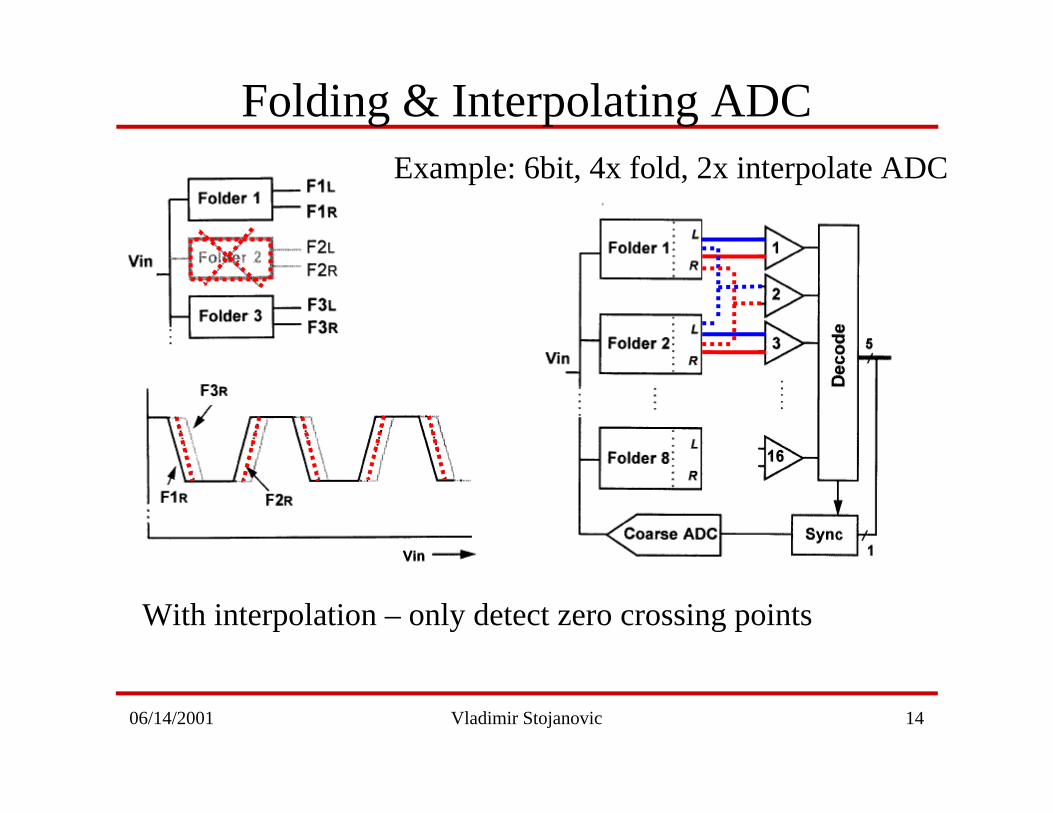
Folding & Interpolating ADC
With interpolation – only detect zero crossing points
Example: 6bit, 4x fold, 2x interpolate ADC
06/14/2001 Vladimir Stojanovic 15
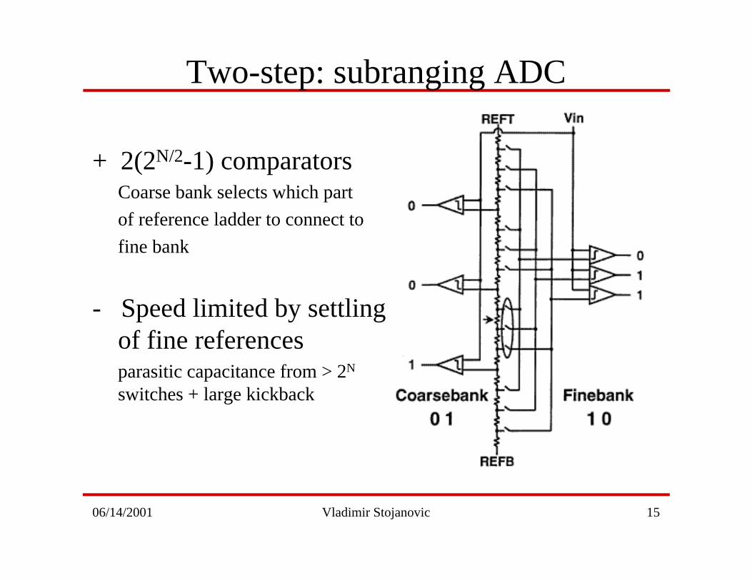
Two-step: subranging ADC
+ 2(2N/2-1) comparatorsCoarse bank selects which part
of reference ladder to connect to
fine bank
- Speed limited by settlingof fine referencesparasitic capacitance from > 2N
switches + large kickback
06/14/2001 Vladimir Stojanovic 16
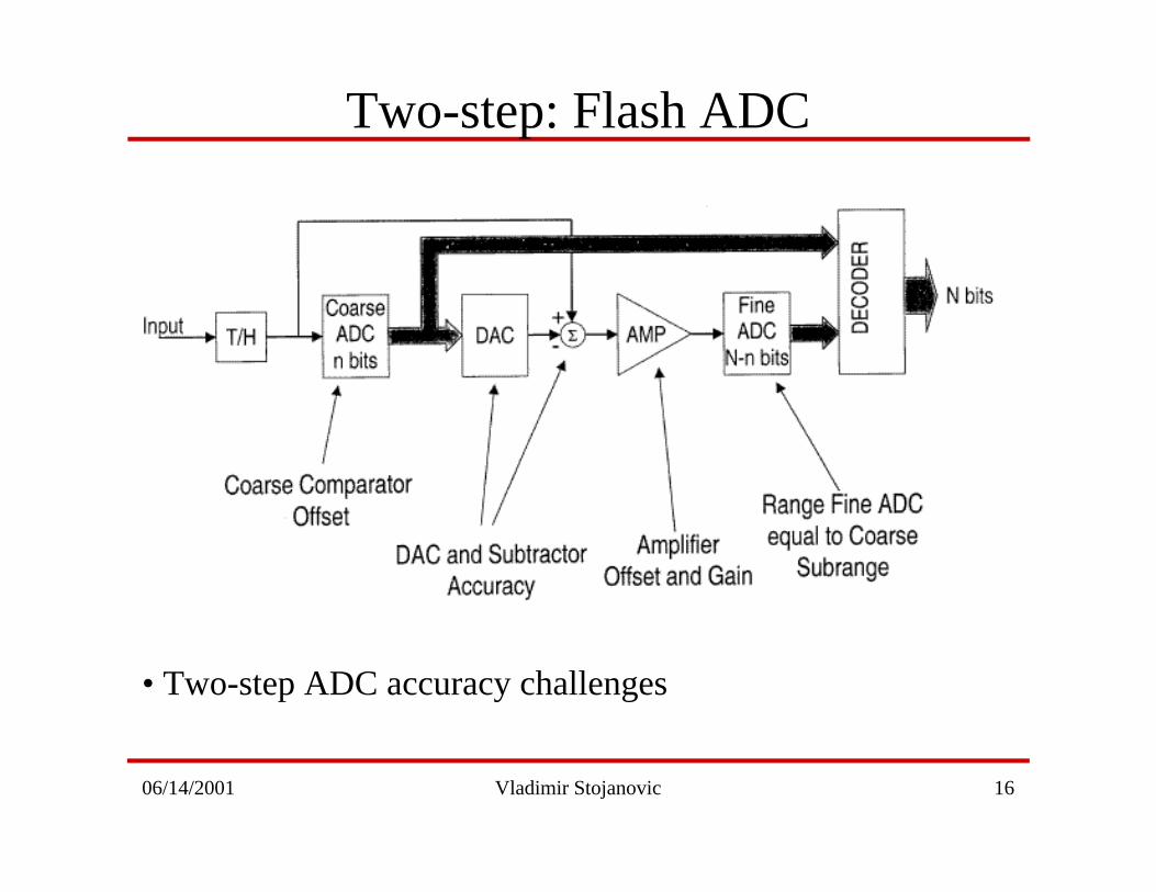
Two-step: Flash ADC
• Two-step ADC accuracy challenges
06/14/2001 Vladimir Stojanovic 17
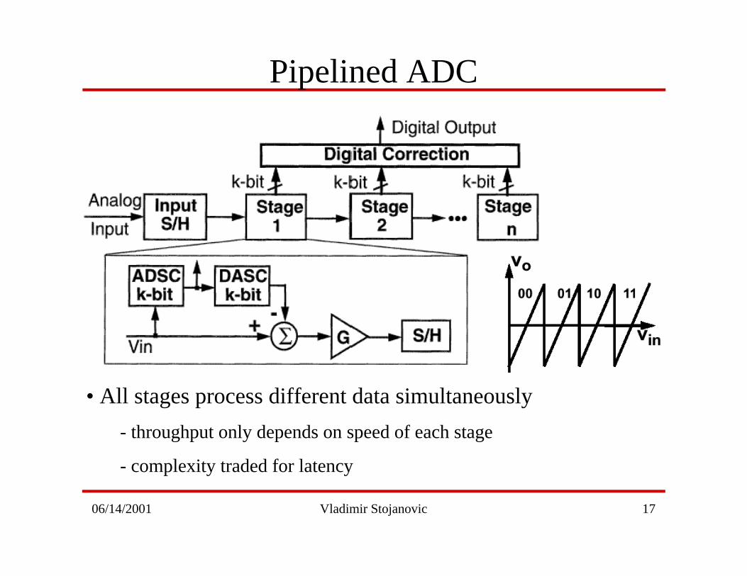
Pipelined ADC
• All stages process different data simultaneously
- throughput only depends on speed of each stage
- complexity traded for latency
06/14/2001 Vladimir Stojanovic 18
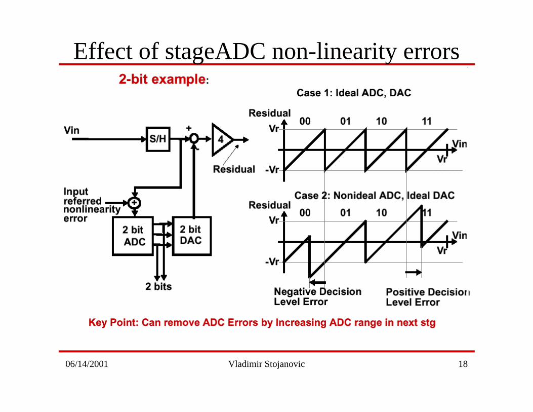
Effect of stageADC non-linearity errors
06/14/2001 Vladimir Stojanovic 19
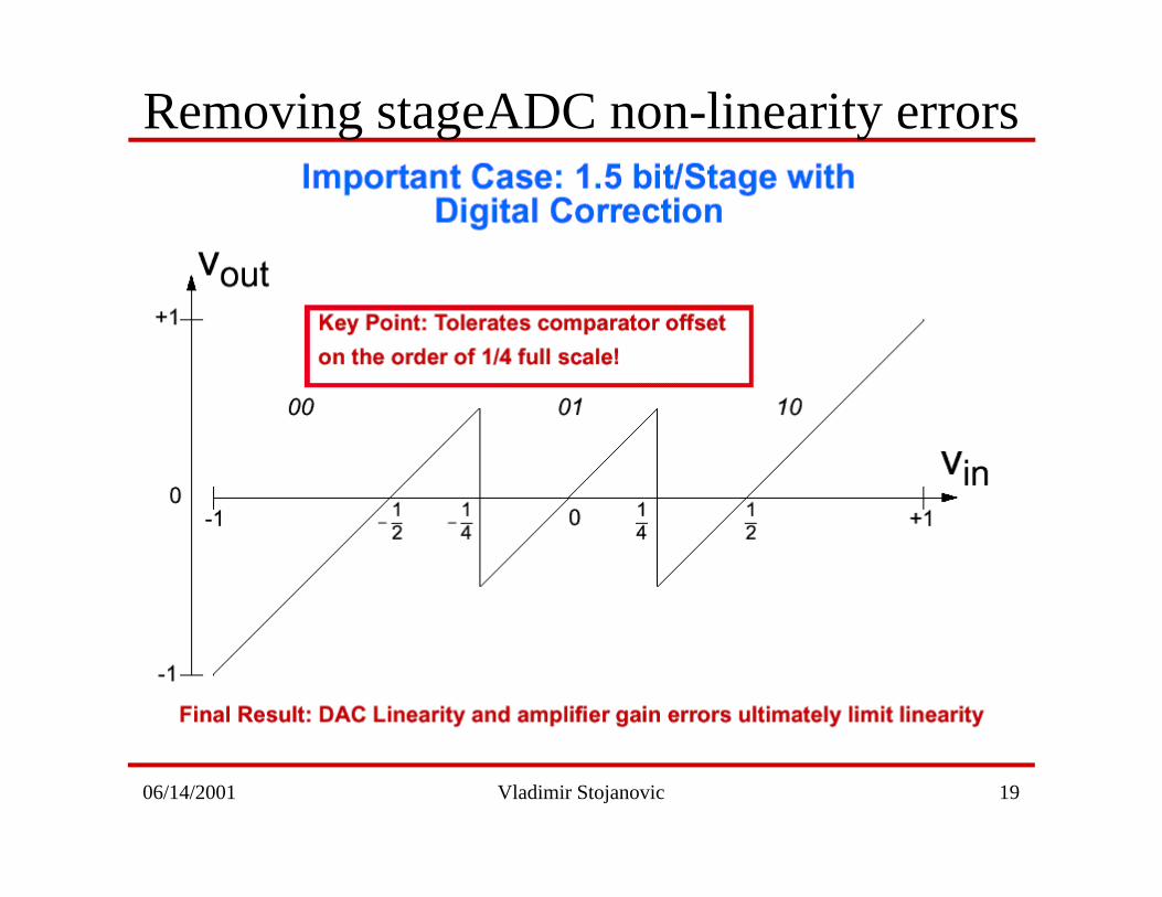
Removing stageADC non-linearity errors
06/14/2001 Vladimir Stojanovic 20
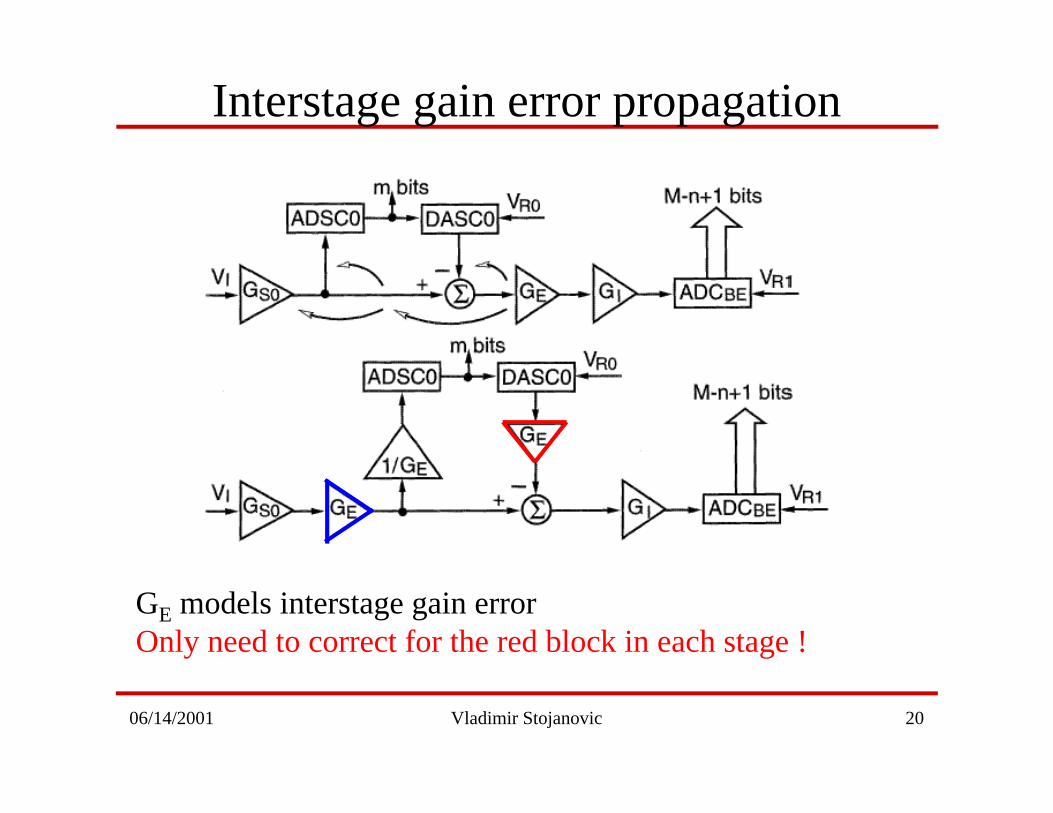
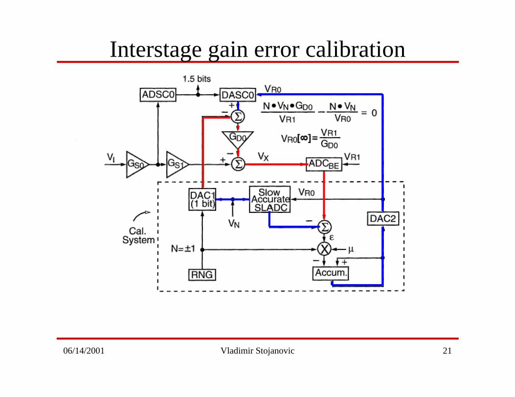
Interstage gain error propagation
GE models interstage gain errorOnly need to correct for the red block in each stage !
06/14/2001 Vladimir Stojanovic 21
Interstage gain error calibration
06/14/2001 Vladimir Stojanovic 22
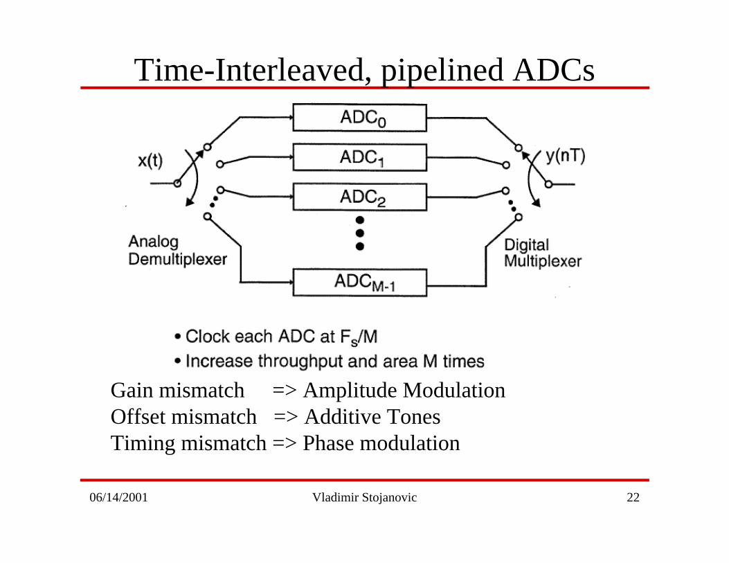
Time-Interleaved, pipelined ADCs
Gain mismatch => Amplitude ModulationOffset mismatch => Additive TonesTiming mismatch => Phase modulation
06/14/2001 Vladimir Stojanovic 23
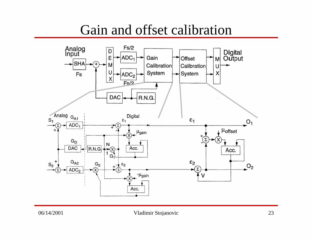
Gain and offset calibration
06/14/2001 Vladimir Stojanovic 24
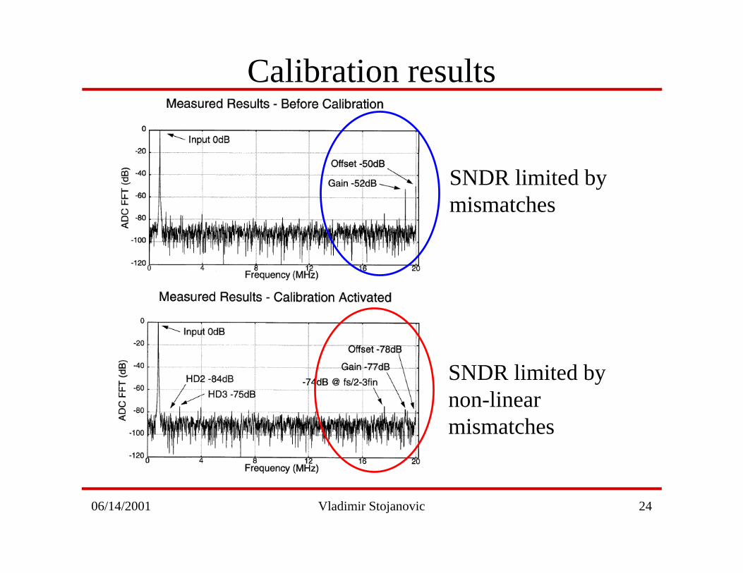
Calibration results
SNDR limited by mismatches
SNDR limited by non-linear mismatches
06/14/2001 Vladimir Stojanovic 25
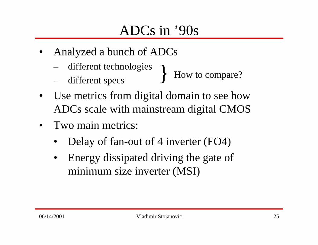
• Analyzed a bunch of ADCs– different technologies
– different specs
• Use metrics from digital domain to see howADCs scale with mainstream digital CMOS
• Two main metrics:
• Delay of fan-out of 4 inverter (FO4)
• Energy dissipated driving the gate ofminimum size inverter (MSI)
ADCs in ’90s
How to compare?}
06/14/2001 Vladimir Stojanovic 26
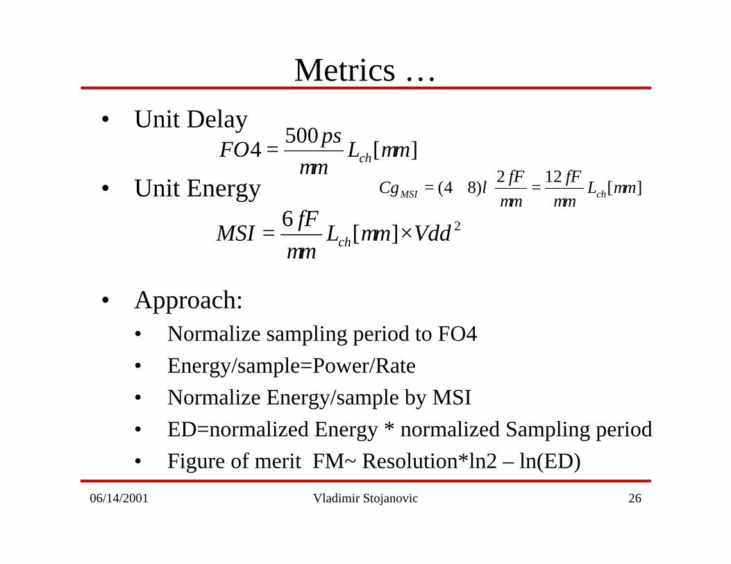
• Unit Delay
• Unit Energy
• Approach:• Normalize sampling period to FO4
• Energy/sample=Power/Rate
• Normalize Energy/sample by MSI
• ED=normalized Energy * normalized Sampling period
• Figure of merit FM~ Resolution*ln2 – ln(ED)
Metrics …
][500
4 mLm
psFO ch µ
µ=
][122
)84( mLm
fF
m
fFCg chMSI µ
µµλ =+=
2][6
VddmLm
fFMSI ch ×= µ
µ
06/14/2001 Vladimir Stojanovic 27
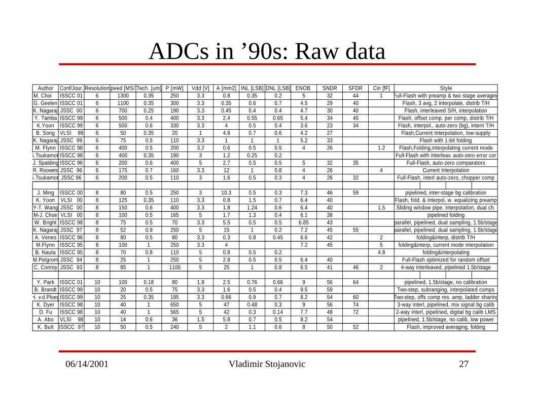
ADCs in ’90s: Raw dataAuthor Conf/Jour. ResolutionSpeed [MS/s]Tech. [um] P [mW] Vdd [V] A [mm2] INL [LSB] DNL [LSB] ENOB SNDR SFDR Cin [fF]
M. Choi ISSCC 01 6 1300 0.35 250 3.3 0.8 0.35 0.2 5 32 44 1G. Geelen ISSCC 01 6 1100 0.35 300 3.3 0.35 0.6 0.7 4.5 29 40K. Nagaraj JSSC 00 6 700 0.25 190 3.3 0.45 0.4 0.4 4.7 30 40Y. Tamba ISSCC 99 6 500 0.4 400 3.3 2.4 0.55 0.65 5.4 34 45K.Yoon ISSCC 99 6 500 0.6 330 3.3 4 0.5 0.4 3.6 23 34B. Song VLSI 99 6 50 0.35 20 1 4.8 0.7 0.6 4.2 27
K. Nagaraj JSSC 99 6 75 0.5 110 3.3 1 1 1 5.2 33M. Flynn ISSCC 98 6 400 0.5 200 3.2 0.6 0.5 0.5 4 26 1.2
S.TsukamotoISSCC 98 6 400 0.35 190 3 1.2 0.25 0.2J. Spalding ISSCC 96 6 200 0.6 400 5 2.7 0.5 0.5 5 32 35R. Roovers JSSC 96 6 175 0.7 160 3.3 12 1 0.8 4 26 4
S.TsukamotoJSSC 96 6 200 0.5 110 3 1.6 0.5 0.3 4 26 32
J. Ming ISSCC 00 8 80 0.5 250 3 10.3 0.5 0.3 7.3 46 59K. Yoon VLSI 00 8 125 0.35 110 3.3 0.8 1.5 0.7 6.4 40
Y-T. Wang JSSC 00 8 150 0.6 400 3.3 1.8 1.24 0.6 6.4 40 1.5M-J. Choe VLSI 00 8 100 0.5 165 5 1.7 1.3 0.4 6.1 38W. Bright ISSCC 98 8 75 0.5 70 3.3 5.5 0.5 0.5 6.85 43K. Nagaraj JSSC 97 8 52 0.9 250 5 15 1 0.2 7.2 45 55A. Venes ISSCC 96 8 80 0.5 80 3.3 0.3 0.8 0.45 6.6 42 2M.Flynn ISSCC 95 8 100 1 250 3.3 4 7.2 45 5B. Nauta ISSCC 95 8 70 0.8 110 5 0.8 0.5 0.2 4.8
M.Pelgrom JSSC 94 8 25 1 250 5 2.8 0.5 0.5 6.4 40C. Conroy JSSC 93 8 85 1 1100 5 25 1 0.8 6.5 41 46 2
Y. Park ISSCC 01 10 100 0.18 80 1.8 2.5 0.76 0.66 9 56 64B. Brandt ISSCC 99 10 20 0.5 75 3.3 1.6 0.5 0.4 9.5 59
H. v.d.PloegISSCC 99 10 25 0.35 195 3.3 0.66 0.9 0.7 8.2 54 60K. Dyer ISSCC 98 10 40 1 650 5 47 0.48 0.3 9 56 74D. Fu ISSCC 98 10 40 1 565 5 42 0.3 0.14 7.7 48 72
A. Abo VLSI 98 10 14 0.6 36 1.5 5.8 0.7 0.5 8.2 54K. Bult ISSCC 97 10 50 0.5 240 5 2 1.1 0.6 8 50 52
pipelined, 1.5b/stage, no calibration
4-way interleaved, pipelined 1.5b/stageFull-Flash optimized for random offset
StyleFull-Flash with preamp & two stage averaging
Flash, 3 avg, 2 interpolate, distrib T/H
Full-Flash, auto-zero comparators
Flash, interleaved S/H, interpolationFlash, offset comp. per comp, distrib T/HFlash, interpol., auto-zero (bg), intern T/H
Flash,Current Interpolation, low-supply
folding&interp, distrib T/Hfolding&interp, current mode interpolation
folding&interpolating
Flash, fold. & interpol, w. equalizing preampSliding window pipe. interpolation, dual ch.
pipelined foldingparallel, pipelined, dual sampling, 1.5b/stageparallel, pipelined, dual sampling, 1.5b/stage
Current InterpolationFull-Flash, interl auto-zero, chopper comp
pipelined, inter-stage bg calibration
Flash with 1-bit foldingFlash,Folding,interpolating current mode
Full-Flash with interleav. auto-zero error cor
pipelined, 1.5b/stage, no calib, low powerFlash, improved averaging, folding
Two-step, subranging, interpolated compsTwo-step, offs comp res. amp, ladder sharing
3-way interl, pipelined, mix signal bg calib2-way interl, pipelined, digital bg calib LMS
06/14/2001 Vladimir Stojanovic 28
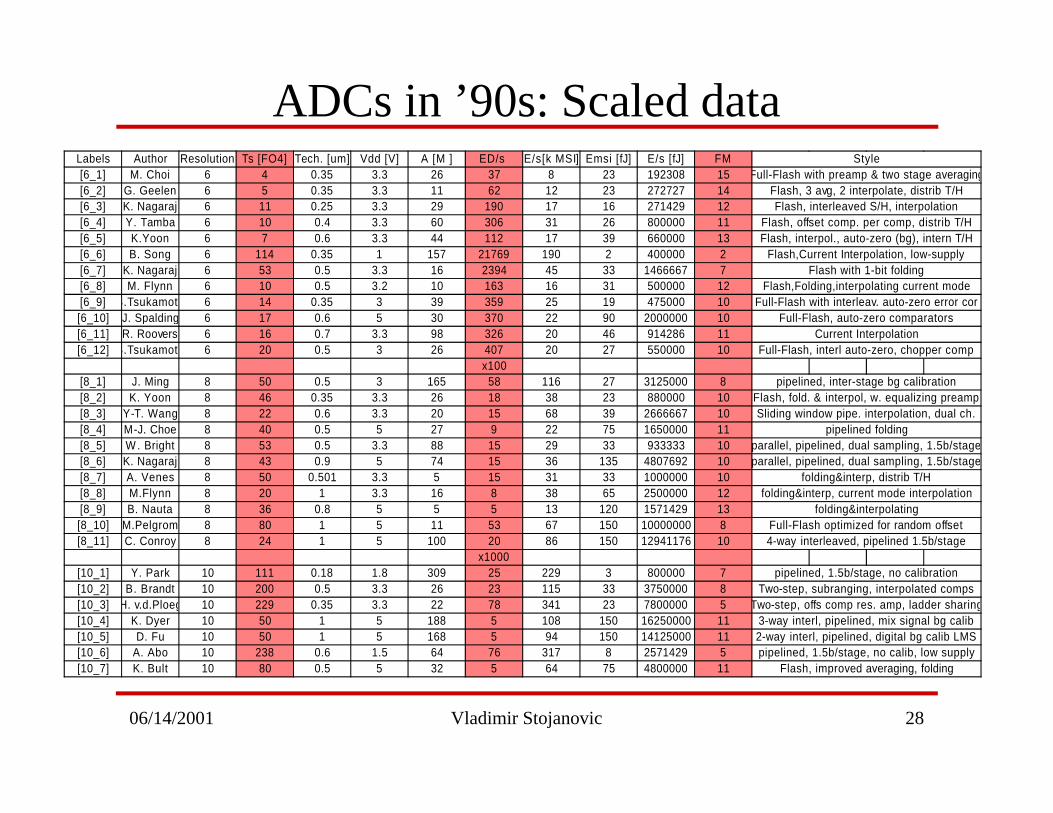
ADCs in ’90s: Scaled dataLabels Author Resolution Ts [FO4] Tech. [um] Vdd [V] A [M ] ED/s E/s[k MSI] Emsi [fJ] E/s [fJ] FM[6_1] M. Choi 6 4 0.35 3.3 26 37 8 23 192308 15[6_2] G. Geelen 6 5 0.35 3.3 11 62 12 23 272727 14[6_3] K. Nagaraj 6 11 0.25 3.3 29 190 17 16 271429 12[6_4] Y. Tamba 6 10 0.4 3.3 60 306 31 26 800000 11[6_5] K.Yoon 6 7 0.6 3.3 44 112 17 39 660000 13[6_6] B. Song 6 114 0.35 1 157 21769 190 2 400000 2[6_7] K. Nagaraj 6 53 0.5 3.3 16 2394 45 33 1466667 7[6_8] M. Flynn 6 10 0.5 3.2 10 163 16 31 500000 12[6_9] S.Tsukamoto 6 14 0.35 3 39 359 25 19 475000 10[6_10] J. Spalding 6 17 0.6 5 30 370 22 90 2000000 10[6_11] R. Roovers 6 16 0.7 3.3 98 326 20 46 914286 11[6_12] S.Tsukamoto 6 20 0.5 3 26 407 20 27 550000 10
x100[8_1] J. Ming 8 50 0.5 3 165 58 116 27 3125000 8[8_2] K. Yoon 8 46 0.35 3.3 26 18 38 23 880000 10[8_3] Y-T. Wang 8 22 0.6 3.3 20 15 68 39 2666667 10[8_4] M-J. Choe 8 40 0.5 5 27 9 22 75 1650000 11[8_5] W . Bright 8 53 0.5 3.3 88 15 29 33 933333 10[8_6] K. Nagaraj 8 43 0.9 5 74 15 36 135 4807692 10[8_7] A. Venes 8 50 0.501 3.3 5 15 31 33 1000000 10[8_8] M.Flynn 8 20 1 3.3 16 8 38 65 2500000 12[8_9] B. Nauta 8 36 0.8 5 5 5 13 120 1571429 13[8_10] M.Pelgrom 8 80 1 5 11 53 67 150 10000000 8[8_11] C. Conroy 8 24 1 5 100 20 86 150 12941176 10
x1000[10_1] Y. Park 10 111 0.18 1.8 309 25 229 3 800000 7[10_2] B. Brandt 10 200 0.5 3.3 26 23 115 33 3750000 8[10_3] H. v.d.Ploeg 10 229 0.35 3.3 22 78 341 23 7800000 5[10_4] K. Dyer 10 50 1 5 188 5 108 150 16250000 11[10_5] D. Fu 10 50 1 5 168 5 94 150 14125000 11[10_6] A. Abo 10 238 0.6 1.5 64 76 317 8 2571429 5[10_7] K. Bult 10 80 0.5 5 32 5 64 75 4800000 11
StyleFull-Flash with preamp & two stage averaging
Flash, 3 avg, 2 interpolate, distrib T/HFlash, interleaved S/H, interpolation
Flash, offset comp. per comp, distrib T/HFlash, interpol., auto-zero (bg), intern T/H
Flash,Current Interpolation, low-supplyFlash with 1-bit folding
Full-Flash, interl auto-zero, chopper comp
pipelined, inter-stage bg calibrationFlash, fold. & interpol, w. equalizing preamp
Flash,Folding,interpolating current modeFull-Flash with interleav. auto-zero error cor
Full-Flash, auto-zero comparatorsCurrent Interpolation
Sliding window pipe. interpolation, dual ch.pipelined folding
parallel, pipelined, dual sampling, 1.5b/stageparallel, pipelined, dual sampling, 1.5b/stage
folding&interp, distrib T/Hfolding&interp, current mode interpolation
folding&interpolatingFull-Flash optimized for random offset
Flash, improved averaging, folding
Two-step, offs comp res. amp, ladder sharing3-way interl, pipelined, mix signal bg calib2-way interl, pipelined, digital bg calib LMSpipelined, 1.5b/stage, no calib, low supply
4-way interleaved, pipelined 1.5b/stage
pipelined, 1.5b/stage, no calibrationTwo-step, subranging, interpolated comps
06/14/2001 Vladimir Stojanovic 29
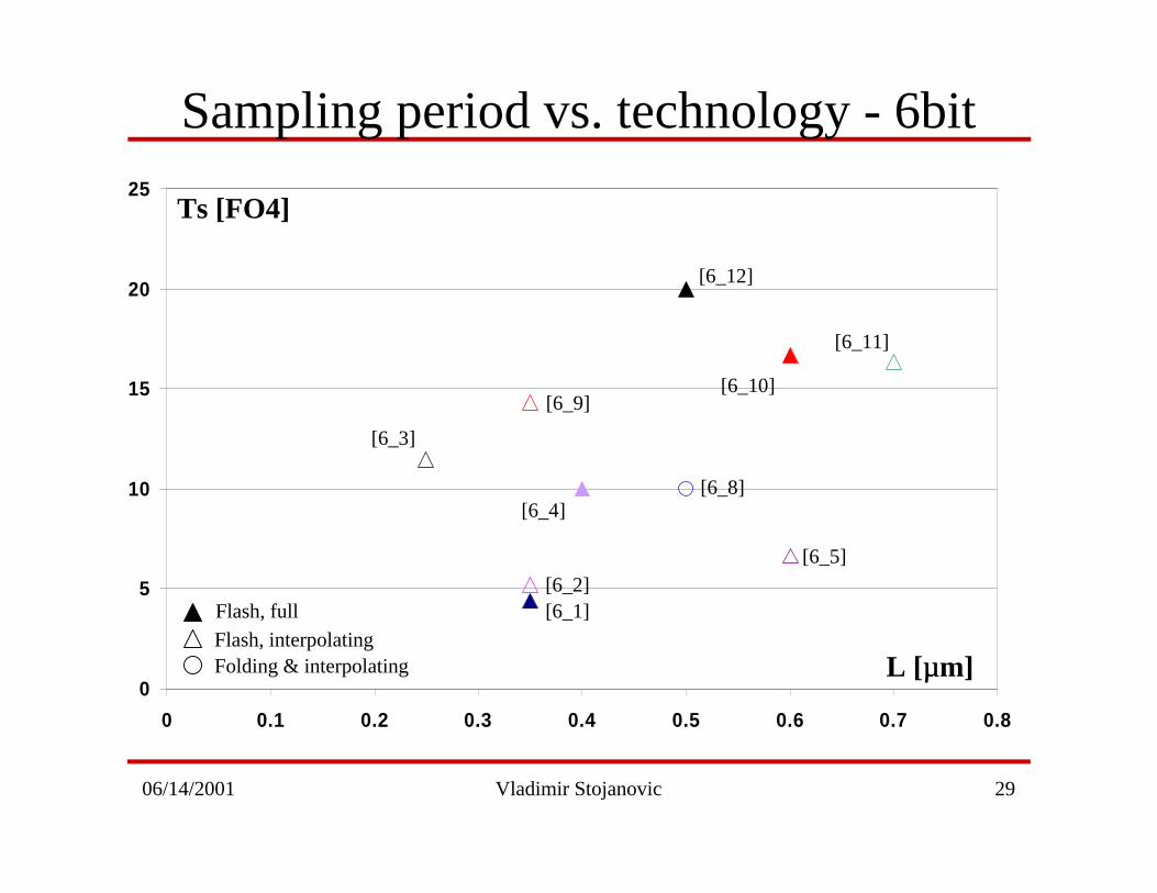
Sampling period vs. technology - 6bit
0
5
10
15
20
25
0 0.1 0.2 0.3 0.4 0.5 0.6 0.7 0.8
L [µµm]
Ts [FO4]
[6_3]
[6_1][6_2]
[6_4]
[6_9]
[6_8]
[6_12]
[6_5]
[6_10]
[6_11]
Flash, fullFlash, interpolatingFolding & interpolating
06/14/2001 Vladimir Stojanovic 30
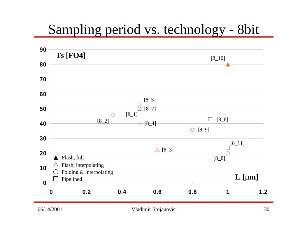
Sampling period vs. technology - 8bit
0
10
20
30
40
50
60
70
80
90
0 0.2 0.4 0.6 0.8 1 1.2
Flash, fullFlash, interpolatingFolding & interpolatingPipelined L [µµm]
Ts [FO4]
[8_2]
[8_8]
[8_3]
[8_4]
[8_5]
[8_9]
[8_10]
[8_11]
[8_6]
[8_7][8_1]
06/14/2001 Vladimir Stojanovic 31
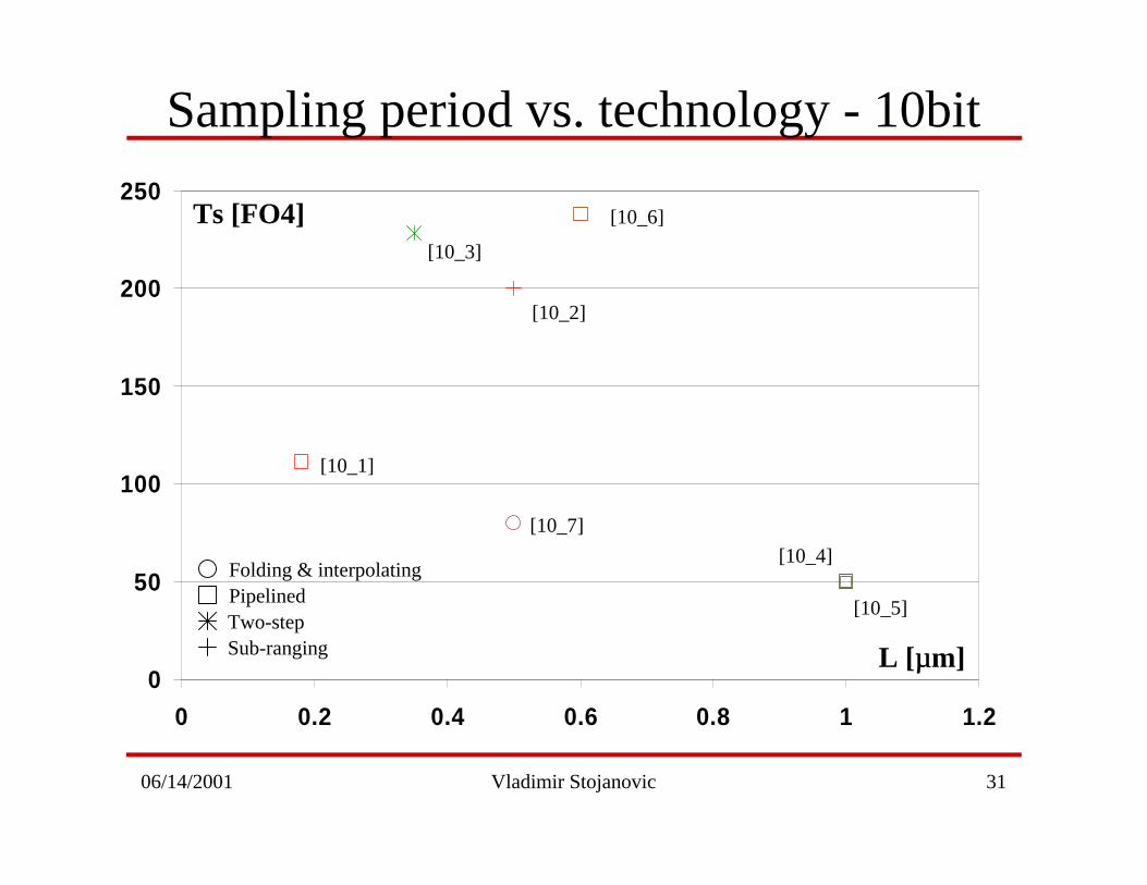
Sampling period vs. technology - 10bit
0
50
100
150
200
250
0 0.2 0.4 0.6 0.8 1 1.2
[10_1]
[10_7]
[10_2]
[10_5]
[10_3]
[10_4]
[10_6]
Folding & interpolatingPipelinedTwo-stepSub-ranging L [µµm]
Ts [FO4]
06/14/2001 Vladimir Stojanovic 32
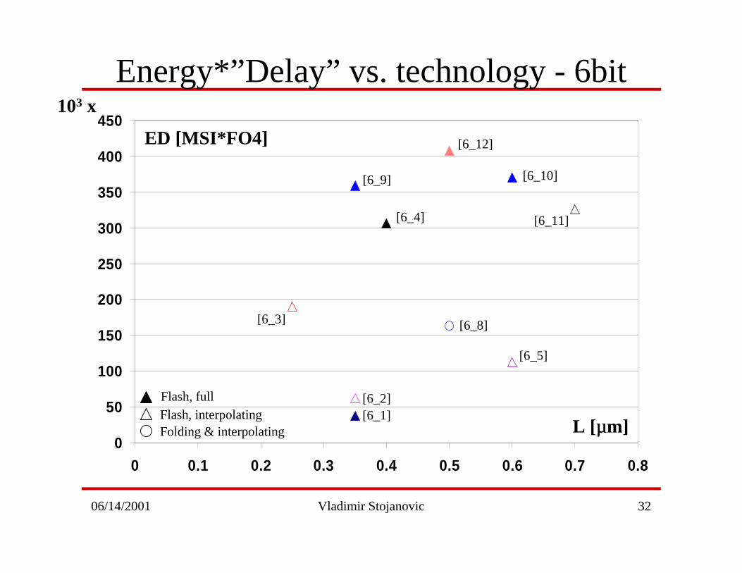
Energy*”Delay” vs. technology - 6bit
0
50
100
150
200
250
300
350
400
450
0 0.1 0.2 0.3 0.4 0.5 0.6 0.7 0.8
L [µµm]
ED [MSI*FO4]
103 x
Flash, fullFlash, interpolatingFolding & interpolating
[6_3]
[6_1][6_2]
[6_4]
[6_9]
[6_8]
[6_12]
[6_5]
[6_10]
[6_11]
06/14/2001 Vladimir Stojanovic 33
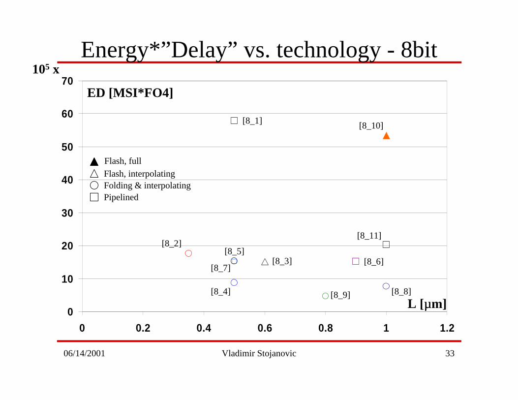
Energy*”Delay” vs. technology - 8bit
0
10
20
30
40
50
60
70
0 0.2 0.4 0.6 0.8 1 1.2
Flash, fullFlash, interpolatingFolding & interpolatingPipelined
[8_2]
[8_8]
[8_3]
[8_4]
[8_5]
[8_9]
[8_10]
[8_11]
[8_6][8_7]
[8_1]
L [µµm]
ED [MSI*FO4]
105 x
06/14/2001 Vladimir Stojanovic 34
0
10
20
30
40
50
60
70
80
90
0 0.2 0.4 0.6 0.8 1 1.2
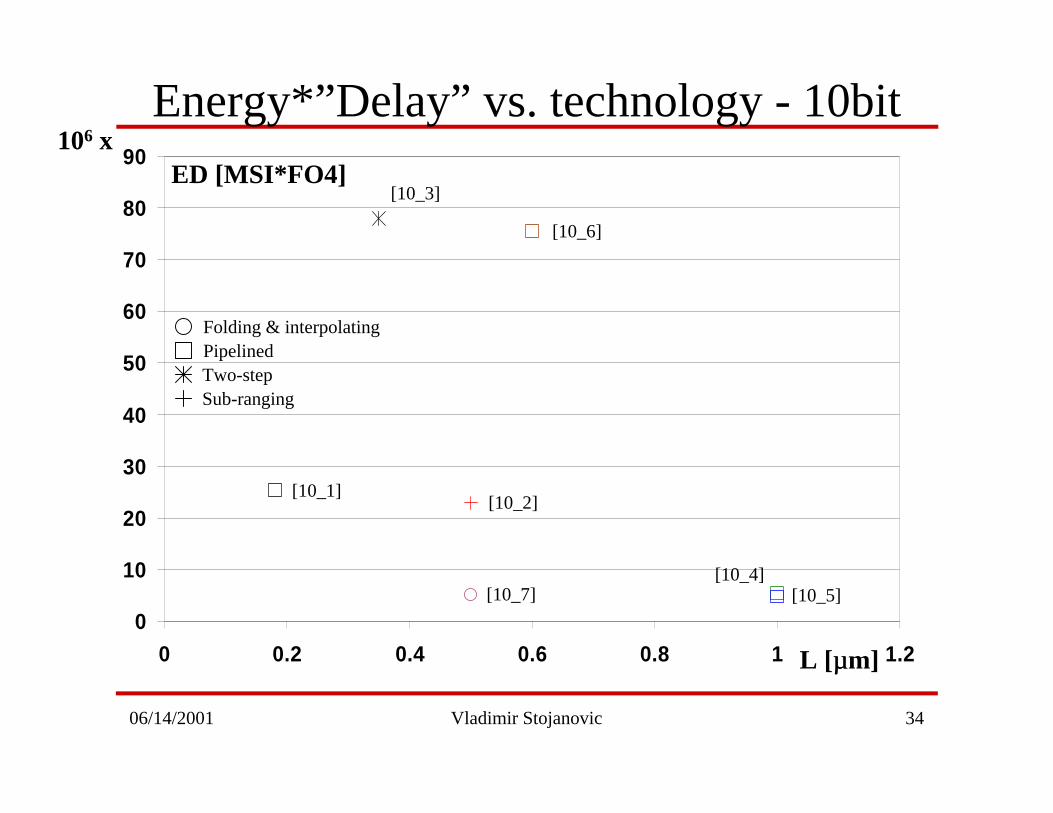
Energy*”Delay” vs. technology - 10bit
L [µµm]
ED [MSI*FO4]106 x
[10_1]
[10_7]
[10_2]
[10_5]
[10_3]
[10_4]
[10_6]
Folding & interpolatingPipelinedTwo-stepSub-ranging
06/14/2001 Vladimir Stojanovic 35
0
2
4
6
8
10
12
14
16
0 0.2 0.4 0.6 0.8 1 1.2
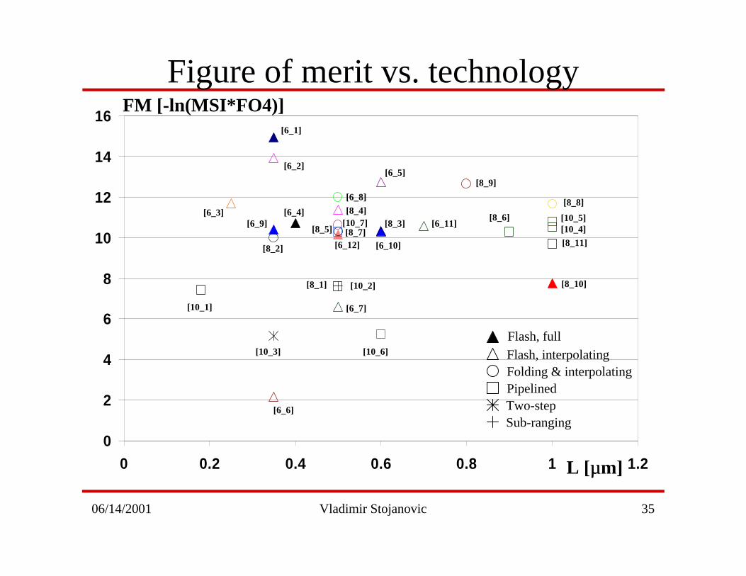
Figure of merit vs. technology
Flash, fullFlash, interpolatingFolding & interpolatingPipelinedTwo-stepSub-ranging
[10_1]
[10_7]
[10_2]
[10_5]
[10_3]
[10_4]
[10_6]
[6_8]
[8_4]
[6_12][8_7][8_5]
[6_6]
[6_7]
[6_10]
[8_3]
[8_1]
[8_2]
[8_9]
[8_6]
[8_8]
[8_11]
[8_10]
[6_1]
[6_2]
[6_3][6_9]
[6_4]
[6_5]
[6_11]
L [µµm]
FM [-ln(MSI*FO4)]
06/14/2001 Vladimir Stojanovic 36
Limiting factors
• Timing errors1. Sampling clock jitter
2. Limited rise/fall time of sampling clock
3. Skew of clock & input signal at different places on the chip
(1ps =100-200 µm on a die)
4. Signal-dependent delay
• Distortion errors1. Sampling comparators’ aperture time
2. Distortion in the linear part of the input amplifier
3. Changes in the reference voltage values & comparator offsets, also
kickback
4. Delays of analog signal and clock signal

06/14/2001 Vladimir Stojanovic 37
• Definition A:
• Definition B:
Timing Error performance limitations
)2(10log20 _ rmstinfSNR επ−=
Nin
ALSBtAf
2
212 =<∆π
inNrmst f23
1_ π
ε <
in
ENOB
rmst fπε
2
10 20/)76.102.6(
_
+−
<
0.1
0.4
2
7
27
B:εtrms [ps]
70.58
30.110
1426
4
2
N
278
5333
C:εtrms [ps]A:εtrms[ps]
For max fin=1GHz
• Definition C:
Taking into account both transmitter and receiver noiseand budgeting 50% for other noise
inLENOBrmst f2/_ 23
1
πε <
06/14/2001 Vladimir Stojanovic 38
Conclusion
• Future – very high speed ADCs• Digitally corrected interpolated Flash
• Time-Interleaved pipelined ADC with channel mismatchcalibration
• Big problem – timing errors• Most of all jitter – after all it is Gaussian noise limit
• Jitter is less of a problem for digital datacommunications
• Spectrum allocation limitations for wireless
• Most of ADCs need not be very, very high speed
06/14/2001 Vladimir Stojanovic 39
References6 bit Converters[6_1] M. Choi and A. Abidi “ A 6b 1.3GSample/s A/D Converter in 0.35µm CMOS,” ISSCC 2001, paper 8.1 [6_2] G. Geelen “ A 6b 1.1GSample/s CMOS A/D Converter,” ISSCC 2001, paper 8.2 [6_3] K. Nagaraj et al. “ Dual Mode A/D Converter,” JSSC 2000, December, vol. 35, no. 12, pp. 1760-68[6_4] Y. Tamba and K. Yamakido “ A CMOS 6b 500MSample/s ADC for a Hard Disk Drive Read Channel,” ISSCC 1999, paper 18.5 [6_5] K. Yoon et al. “ A 6b 500MSample/s CMOS Flash ADC with a Background Interpolated Auto-Zeroing Technique,” ISSCC 1999, paper 18.6[6_6] B. Song et al. “ A 1V 50MHz Current-Interpolating CMOS ADC,” VLSI Symposium 1999, paper 8.3[6_7] K. Nagaraj et al. “ Efficient 6-b A/D Converter Using a 1-bit Folding Front End,” JSSC 1999, August, vol. 34, no. 8, pp. 1056-62[6_8] M. P. Flynn and B. Sheahan “ A 400MSample/s 6b CMOS Folding and Interpolating ADC,” ISSCC 1998, paper 9.7[6_9] S. Tsukamoto et al. “ A CMOS 6b 400MSample/s ADC with Error Correction,” ISSCC 1998, paper 9.8[6_10] J. Spalding and D. Dalton “ A 200MSample/s 6b Flash ADC in 0.6um CMOS,” ISSCC 1996, paper 19.5[6_11] R. Roovers and M. S. J. Steyaert “ A 175Ms/s, 6 b, 160 mW, 3.3 V CMOS A/D Converter,” JSSC 1996, July, vol. 31, no. 7, pp. 938-44 [6_12] S. Tsukamoto et al. “ A CMOS 6-bit, 200Msample/s, 3 V-Supply A/D Converter for a PRML Read Channel LSI,” JSSC 1996, November, vol.31, no. 11, pp. 1831-36
8 bit Converters[8_1] J. Ming and S. H. Lewis “ An 8b 80MSample/s Pipelined ADC with Background Calibration,” ISSCC 2000, paper 2.5[8_2] K. Yoon et al. “ An 8-bit 125Ms/s CMOS Folding ADC for Gigabit Ethernet LSI,” VLSI Symposium 2000, paper 16.2[8_3] Y. Wang and B. Razavi “ An 8-bit 150-MHz CMOS A/D Converter,” JSSC 2000, March, vol. 35, no. 3, pp. 308-17[8_4] M. Choe et al. “ An 8b 100MSample/s CMOS Pipelined Folding ADC,” VLSI Symposium 1999, paper 8.4
06/14/2001 Vladimir Stojanovic 40
References …[8_5] W. Bright “ 8b 75MSample/s 70mW Parallel Pipelined ADC Incorporating Double Sampling,” ISSCC 1998, paper 9.5[8_6] K. Nagaraj et al. “ A 250-mW, 8-b, 52-Msample/s, Parallel-Pipelined A/D Converter with Reduced Number of Amplifiers,” JSSC 1997, March, vol. 32, no. 3, pp. 312-20[8_7] A. G. W. Venes and R. J. van de Plassche “An 80MHz 80mW 8b CMOS Folding A/D Converter with Distributed T/H Preprocessing,” ISSCC 1996, paper 19.4 [8_8] M. P. Flynn and D. J. Allstot “ CMOS Folding ADCs with Current-Mode Interpolation,” ISSCC 1995, paper 16.2[8_9] B. Nauta and A. G. W. Venes “A 70MSample/s 110mW 8b CMOS Folding Interpolating A/D Converter,” ISSCC 1995, paper 16.3 [8_10] M. Pelgrom et al. “ A 25-Ms/s 8-bit CMOS A/D Converter for Embedded Application,” JSSC 1994, August, vol. 29, no. 8, pp. 879-86[8_11] C. Conroy et al. “ An 8-bit 85MS/s Parallel-Pipeline A/D Converter in 1-um CMOS,” JSSC 1993, April, vol. 28, no. 4, pp. 447-54
10 bit Converters[10_1] Y. Park et al. “ A 10b 100MSample/s CMOS Piplined ADC with 1.8V Power Supply,” ISSCC 2001, paper 8.3[10_2] B. Brandt and J. Lutsky “ A 75mW 10b 20MSample/s CMOS Subranging ADC with 59dB SNDR,” ISSCC 1999, paper 18.4[10_3] H. van der Ploeg and R. Remmers “ A 3.3V 10b 25MSample/s Two-Step ADC in 0.35um CMOS,” ISSCC 1999, paper 18.2 [10_4] K. Dyer et al. “ Analog Background Calibration of a 10b 40MSample/s Parallel Pipelined ADC,” ISSCC 1998, paper 9.3[10_5] D. Fu et al. “ Digital Background Calibration of a 10b 40MSample/s Parallel Pipelined ADC,” ISSCC 1998, paper 9.2[10_6] A. M. Abo and P. R. Gray “A 1.5V, 10-bit, 14MS/s CMOS Pipeline Analog-to-Digital Converter,” VLSI Symposium 1998, paper 14.2[10_7] K. Bult et al. “ A 170mW 10b 50MSample/s CMOS ADC in 1mm2,” ISSCC 1997, paper 8.3