Embed Size (px)
Citation preview
VSR BLASTER® air cannonsfor pneumatic activation of bulk materialsin silos and processing plants
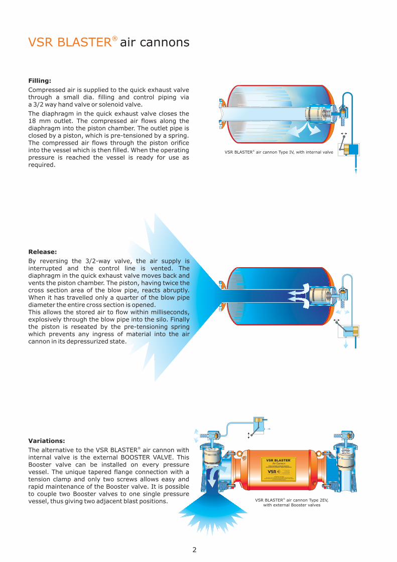
VSR BLASTER air cannonwith external Booster valves
® Type 2EV,
VSR BLASTER air cannon with internal valve® Type IV,
Release:
By reversing the 3/2-way valve, the air supply isinterrupted and the control line is vented. Thediaphragm in the quick exhaust valve moves back andvents the piston chamber. The piston, having twice thecross section area of the blow pipe, reacts abruptly.When it has travelled only a quarter of the blow pipediameter the entire cross section is opened.This allows the stored air to flow within milliseconds,explosively through the blow pipe into the silo. Finallythe piston is reseated by the pre-tensioning springwhich prevents any ingress of material into the aircannon in its depressurized state.
VSR BLASTER® air cannons
Filling:
Compressed air is supplied to the quick exhaust valvethrough a small dia. filling and control piping viaa 3/2 way hand valve or solenoid valve.
The diaphragm in the quick exhaust valve closes the18 mm outlet. The compressed air flows along thediaphragm into the piston chamber. The outlet pipe isclosed by a piston, which is pre-tensioned by a spring.The compressed air flows through the piston orificeinto the vessel which is then filled. When the operatingpressure is reached the vessel is ready for use asrequired.
Variations:
The alternative to the VSR BLASTER air cannon withinternal valve is the external BOOSTER VALVE. ThisBooster valve can be installed on every pressurevessel. The unique tapered flange connection with atension clamp and only two screws allows easy andrapid maintenance of the Booster valve. It is possibleto couple two Booster valves to one single pressurevessel, thus giving two adjacent blast positions.
®
2

High temperature application: riser duct with changeable nozzle system
Design advantages:
�
�
�
�
�
�
The superior effect of the VSR BLASTER air cannon is achieved by the unrestricted flow of compressed air fromthe pressure vessel to the discharge pipe.
The big piston with twice the diameter of the blowing pipe effects an extremely high piston lifting speed. With apiston travel of a quarter of the blowing pipe diameter, the ring orifice is fully opened for direct inflow. In thisway, the explosive air expansion is achieved.
Quick exhausting of the piston chamber is done by a large ¾ ” quick exhaust valve with a Viton diaphragm whichis specially developed and directly positioned at the piston chamber.
Maintenance work on the piston can be carried out without dismounting the vessel by simply removing therear cap.
A spring pushes the piston immediately back and prevents material and dust from penetrating into the vessel.An impact area at the piston absorbs the recoil.
Filling and control are carried out through a small 8x1 mm piping which is easily to be installed. Severalcontrol valves can be housed in protective control boxes in easily accessible places. No electric cables have to beconnected to the air cannons.
®
�
Typical problems and solutions
3
Funneling Ratholing Bridging Arching
VSR BLASTER air cannons in a cement plant (Foto: Krupp Polysius)®
Effect:
The VSR BLASTER air cannon instantaneously expells an explosion charge of compressed air directly into thecritical areas of silos, hoppers and heat exchangers. This explosive blast of energy destroys the materialadhesion and static friction resulting in a free flow under normal gravity.Air is discharged directly into the material from a straight nozzle or alternatively via a fan shaped head or isobaricsword nozzle in order to spread or concentrate the effort in specific areas.
®
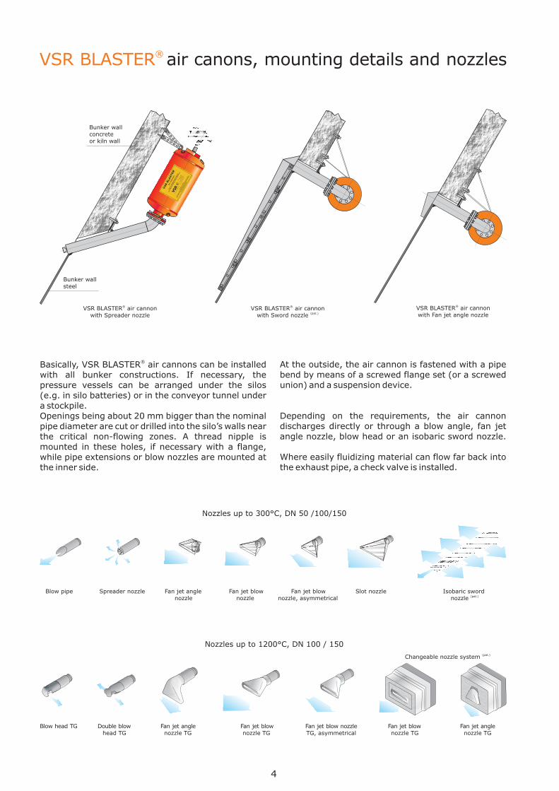
Blow head Double blow et angle Fan jet blow Fan jet blow nozzleTG Fan j Fan jet blow Fan jet anglehead TG nozzle TG nozzle TG TG, asymmetrical nozzle TG nozzle TG
Changeable nozzle system (pat.)
Blow pipe Spreader nozzle Fan jet angle Fan jet blow Fan jet blow Slot nozzle Isobaric swordnozzle nozzle nozzle, asymmetrical nozzle (pat.)
VSR BLASTER air cannonwith Fan jet angle nozzle
®VSR BLASTER air cannonwith Sword nozzle (pat.)
®VSR BLASTER air cannonwith Spreader nozzle
®
VSR BLASTER® air canons, mounting details and nozzles
Basically, VSR BLASTER air cannons can be installedwith all bunker constructions. If necessary, thepressure vessels can be arranged under the silos(e.g. in silo batteries) or in the conveyor tunnel undera stockpile.Openings being about 20 mm bigger than the nominalpipe diameter are cut or drilled into the silo’s walls nearthe critical non-flowing zones. A thread nipple ismounted in these holes, if necessary with a flange,while pipe extensions or blow nozzles are mounted atthe inner side.
® At the outside, the air cannon is fastened with a pipebend by means of a screwed flange set (or a screwedunion) and a suspension device.
Depending on the requirements, the air cannondischarges directly or through a blow angle, fan jetangle nozzle, blow head or an isobaric sword nozzle.
Where easily fluidizing material can flow far back intothe exhaust pipe, a check valve is installed.
4
Bunker wallsteel
Bunker wallconcreteor kiln wall
Nozzles up to 300°C, DN 50 /100/150
Nozzles up to 1200°C, DN 100 / 150
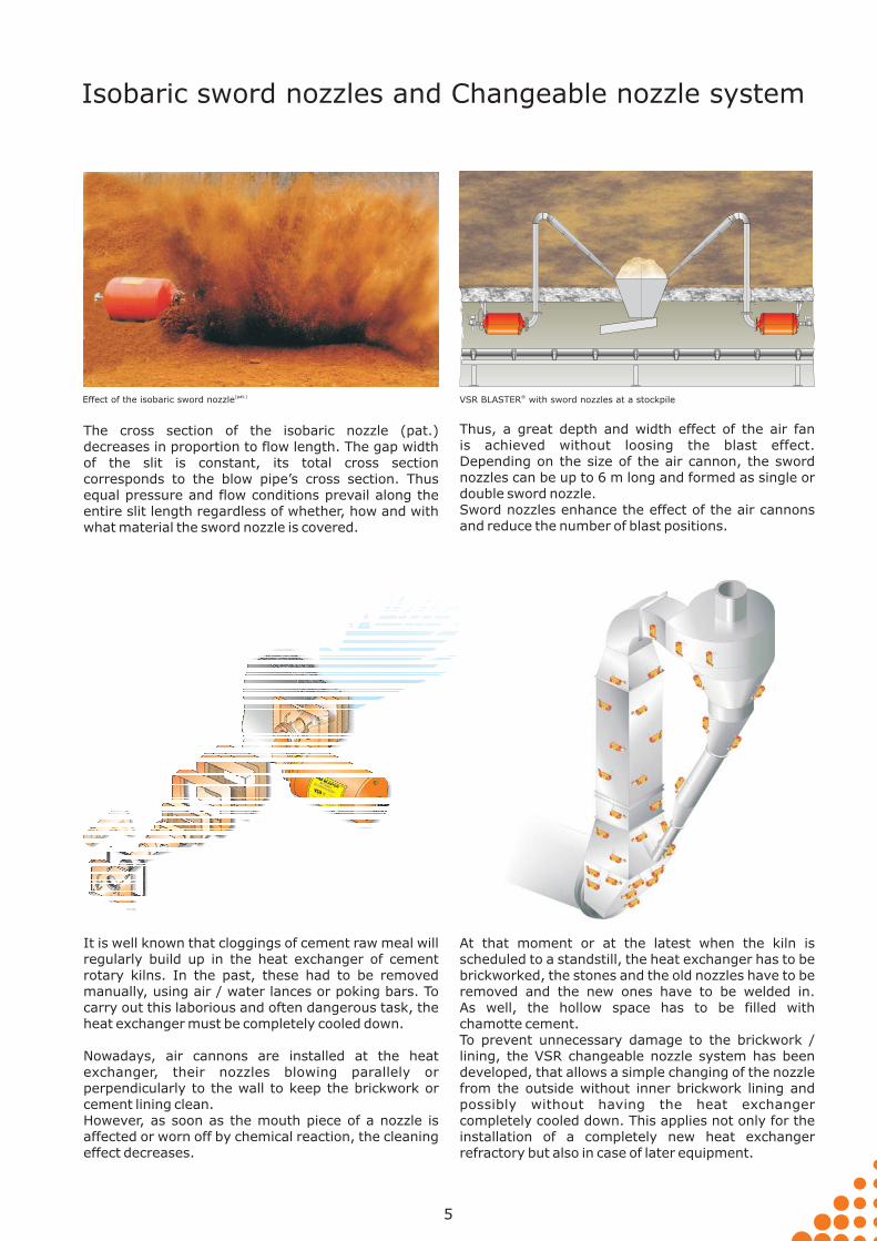
It is well known that cloggings of cement raw meal willregularly build up in the heat exchanger of cementrotary kilns. In the past, these had to be removedmanually, using air / water lances or poking bars. Tocarry out this laborious and often dangerous task, theheat exchanger must be completely cooled down.
Nowadays, air cannons are installed at the heatexchanger, their nozzles blowing parallely orperpendicularly to the wall to keep the brickwork orcement lining clean.However, as soon as the mouth piece of a nozzle isaffected or worn off by chemical reaction, the cleaningeffect decreases.
At that moment or at the latest when the kiln isscheduled to a standstill, the heat exchanger has to bebrickworked, the stones and the old nozzles have to beremoved and the new ones have to be welded in.As well, the hollow space has to be filled withchamotte cement.To prevent unnecessary damage to the brickwork /lining, the VSR changeable nozzle system has beendeveloped, that allows a simple changing of the nozzlefrom the outside without inner brickwork lining andpossibly without having the heat exchangercompletely cooled down. This applies not only for theinstallation of a completely new heat exchangerrefractory but also in case of later equipment.
VSR BLASTER with sword nozzles at a stockpile®Effect of the isobaric sword nozzle(pat.)
Thus, a great depth and width effect of the air fanis achieved without loosing the blast effect.Depending on the size of the air cannon, the swordnozzles can be up to 6 m long and formed as single ordouble sword nozzle.Sword nozzles enhance the effect of the air cannonsand reduce the number of blast positions.
The cross section of the isobaric nozzle (pat.)decreases in proportion to flow length. The gap widthof the slit is constant, its total cross sectioncorresponds to the blow pipe’s cross section. Thusequal pressure and flow conditions prevail along theentire slit length regardless of whether, how and withwhat material the sword nozzle is covered.
5
Isobaric sword nozzles and Changeable nozzle system

In general, fill and control tubes not longer than 10 m of stainless steel or copper ø 8x1 are used, with simpleapplications even polyamid tubes. Cutting ring couplings have to be used to prevent any reduction of the crosssection. The hand valves and solenoid valves can be mounted in groups together with an air service device in awell accessible location. Normally, the solenoid valves will be contained in a protective steel cabinet.
The solenoid valves are controlled by push buttons,or generally by an electronic cycle control that allowsa fully automatic operation. In the simplest form,solenoid valves with adjustable operating time andsubsequent interval cycle card are used.A more universal operation, primarily for largersystems, is permitted by using electronic ormicroprocessor control units. Air cannons should besecured against unauthorized refilling (e.g. duringmaintenance works).
For reasons of safety and effectiveness, in most casesthe air cannons are blown off individually. It is best torelease them in a cycle one after the other frombottom to top.The actuation frequency depends on the problem.They can be fired every minute or once per hour, shift,day or week.
The firing is initiated by hand lever valves or solenoidvalves with auxiliary manual actuation.
Pneumatic control
6
4-10 bar
Ø8x1
1/2”
Internet: www.vsr-industrietechnik.de E-mail: [email protected]
VSR Industrietechnik GmbH
Am Alten Schacht 6
D- 47198 Duisburg
/ -
/ -
Tel. +49 (0) 20 66 99 66 30
Fax +49 (0) 20 66 99 66 62
Internet: www.vsr-industrietechnik.de E-mail: [email protected]
VSR Industrietechnik GmbH
Am Alten Schacht 6
D- 47198 Duisburg
/ -
/ -
Tel. +49 (0) 20 66 99 66 30
Fax +49 (0) 20 66 99 66 62
Solenoid valve casewith pressure control and safety aerating
Electronic S7 control unit for large systems
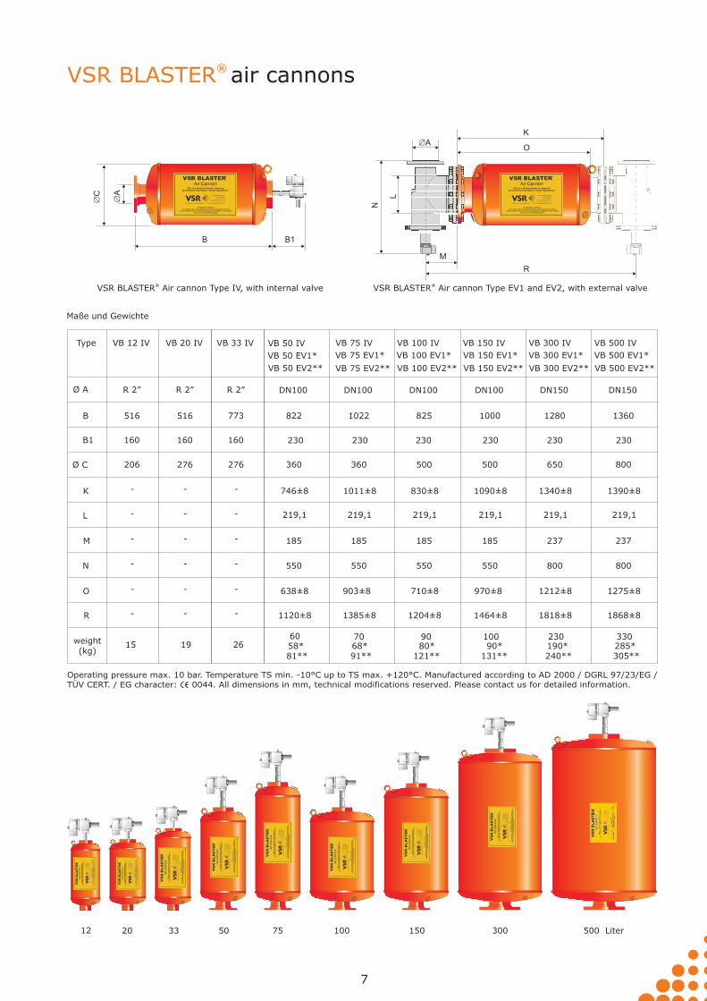
Operating pressure max. 10 bar. Temperature TS min. -10°C up to TS max. +120°C. Manufactured according to AD 2000 / DGRL 97/23/EG /TÜV CERT. / EG character: 0044. Please contact us for detailed information.All dimensions in mm, technical modifications reserved.
VSR BLASTER Air cannon Type EV1 and EV2, with external valve®VSR BLASTER Air cannon Type IV, with internal valve®
VSR BLASTER® air cannons
12 20 50 75 100 150 300 500 Liter33
�A
�C
B B1
�AO
N
K
L
M
R
7
Maße und Gewichte
Ø A
Type
B
B1
Ø C
K
L
M
R
N
O
weight(kg)
230 230 230 230
DN100
825
500
830±8
219,1
185
1204±8
550
710±8
DN100
1000
500
1090±8
219,1
185
1464±8
550
970±8
DN150
1280
650
1340±8
219,1
237
1818±8
800
1212±8
DN150
1360
800
VB 100 IV VB 150 IV VB 300 IV VB 500 IV
VB 100 EV1* VB 150 EV1* VB 300 EV1* VB 500 EV1*
1390±8
219,1
237
1868±8
800
1275±8
R 2”
516
206
160
-
-
-
-
-
-
VB 12 IV
15
160
R 2”
516
276
-
-
-
-
-
-
VB 20 IV
1990 100 230 330
VB 100 EV2** VB 150 EV2** VB 300 EV2** VB 500 EV2**
80* 90* 190* 285*58*
VB 75 EV1*
68*
230
DN100
1022
360
1011±8
219,1
185
1385±8
550
903±8
VB 75 IV
70
VB 75 EV2**
91** 121** 131** 240** 305**
VB 50 EV1*
230
DN100
822
360
746±8
219,1
185
1120±8
550
638±8
VB 50 IV
60
VB 50 EV2**
81**
160
R 2”
773
276
-
-
-
-
-
-
VB 33 IV
26
Guarantee of EffectVSR BLASTER air cannon systems, when installed according to our individual recommendations, are guaranteed toperform to the customer's satisfaction, or the components may be returned for full credit within a period to be agreed upon.
®
Low Noise level
Simple Installation and Operation
Accident prevention
The noise of the expanding compressed air is almostcompletely absorbed by the bulk material.
The air cannon is mounted with only a few pipe fittingsat the bunker. It will be connected to the compressedair system by means of a 3/2 way valve and can becontrolled by an automatic, electronic control panel.
The VSR BLASTER air cannons meet the pressurevessel safety regulations. There is absolutely nodanger to the bunker itself nor to its contents. Due tothe low volume of compressed air and the use of asparkless valve, there is no danger of initiating anexplosion (e.g. in case of coal dust).
Inert gas, e.g. nitrogen, can be used instead ofcompressed air. Recommendations of the authorizedassociations for silo safety are available.
®
Working medium
High temperature and Pressurized vessels
Low Energy consumption
In most cases, compressed air as supplied by astandard system will be the adequate working medium.
If compressed air is not acceptable in the process,inert gas can be used.
Since the air cannon operates intermittently, itconsumes only a fraction of the energy needed forconventional pneumatic fluidization systems.
The VSR BLASTER air cannons operate in a pressurerange of 4-10 bar with increasing effectiveness. Often,a pressure of 6 bar is sufficient. The operating intervalscan be reduced to less than 5 seconds (if necessary),while often only a few blasts per day are needed.
VSR BLASTER air cannons can be used in hightemperature and pressurized vessels (up to 1100° Cand 6 bar), when special arrangements are provided.
®
®
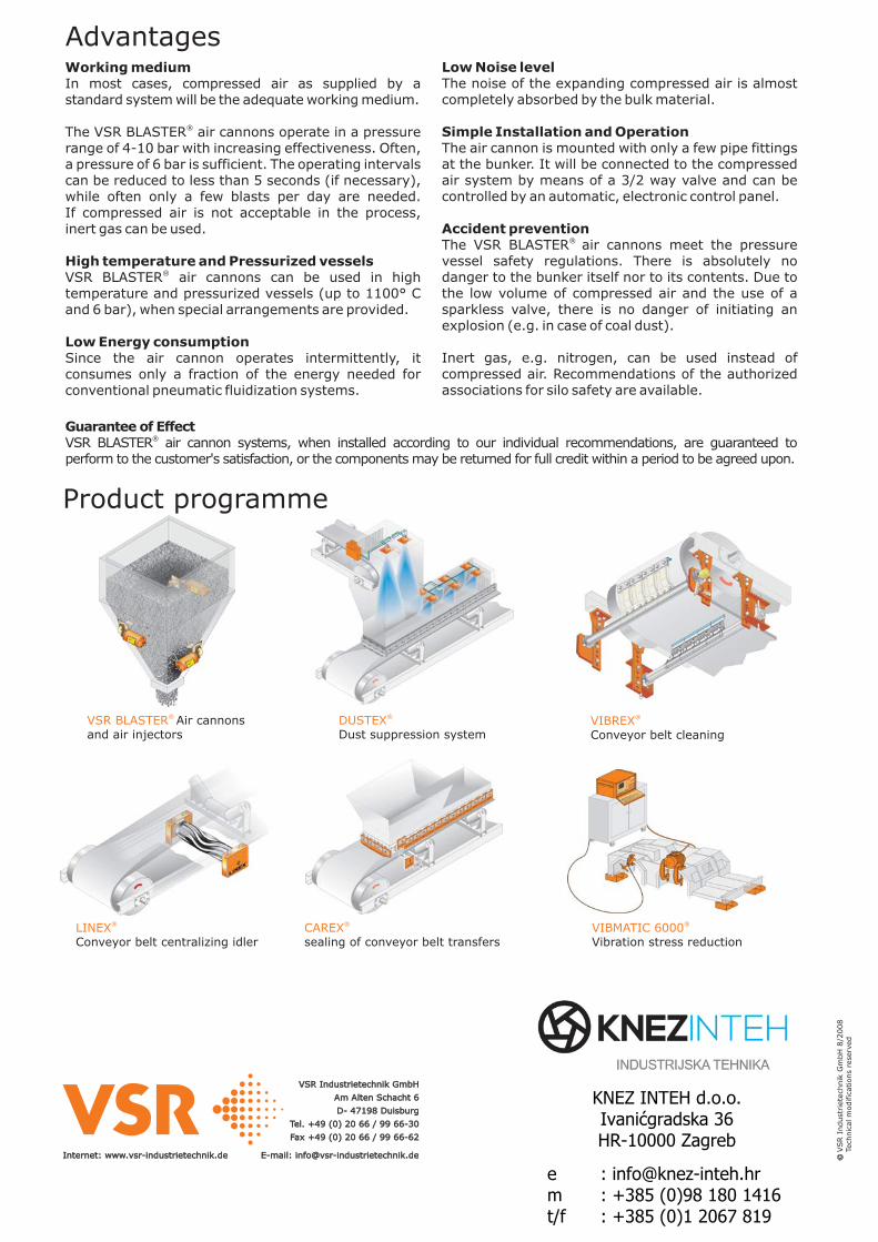
VIBMATIC 6000®
Vibration stress reductionCAREX®
sealing of conveyor belt transfersLINEX®
Conveyor belt centralizing idler
VIBREX®
Conveyor belt cleaningDUSTEX®
Dust suppression systemVSR BLASTER® Air cannonsand air injectors
Product programme
VSR
Indust
riete
chnik
Gm
bH
8/2
008
Tech
nic
alm
odific
ations
rese
rved
Internet: www.vsr-industrietechnik.de E-mail: [email protected]: www.vsr-industrietechnik.de E-mail: [email protected]
VSR Industrietechnik GmbH
Am Alten Schacht 6
D- 47198 Duisburg
Tel. +49 (0) 20 66 / 99 66-30
Fax +49 (0) 20 66 / 99 66-62
VSR Industrietechnik GmbH
Am Alten Schacht 6
D- 47198 Duisburg
Tel. +49 (0) 20 66 / 99 66-30
Fax +49 (0) 20 66 / 99 66-62
Advantages
KNEZ INTEH d.o.o.Ivanićgradska 36HR-10000 Zagreb
e : [email protected] m : +385 (0)98 180 1416 t/f : +385 (0)1 2067 819