Embed Size (px)
Citation preview
570 IEEE TRANSACTIONS ON MULTIMEDIA, VOL. 5, NO. 4, DECEMBER 2003
VSculpt : A Distributed Virtual SculptingEnvironment for Collaborative Design
Frederick W. B. Li, Rynson W. H. Lau, Member, IEEE, and Frederick F. C. Ng
Abstract—A collaborative virtual sculpting system supports ateam of geographically separated designers/engineers connectedby networks to participate in designing three-dimensional (3-D)virtual engineering tools or sculptures. It encourages internationalcollaboration at a minimal cost. However, in order for the systemto be useful, two factors need to be addressed: intuitiveness andreal-time interaction. Although a lot of effort has been put intodeveloping virtual sculpting environments, only limited work ad-dresses collaborative virtual sculpting. This is because in orderto support real-time collaborative virtual sculpting, many chal-lenging issues need to be addressed. In this paper, we propose a col-laborative virtual sculpting framework, called VSculpt . Throughadapting some techniques we developed earlier and integratingthem with some techniques developed here, the proposed frame-work provides a real-time intuitive environment for collaborativedesign. In particular, it addresses issues on efficient rendering andtransmission of deformable objects, intuitive object deformationusing theCyberGloveand concurrent object deformation by mul-tiple clients. We demonstrate and evaluate the performance of theproposed framework through a number of experiments.
Index Terms—Collaborative environments, deformable objectrendering, distributed collaboration, virtual sculpting.
I. INTRODUCTION
W ITH THE introduction of distributed virtual environ-ments, we may now interact and work with each other
via a local network or through the internet, without physicallytravel. This encourages collaborative work from internationalparticipants living at different geographical locations. In [1]and [2], we proposed a framework to support distributedvirtual walkthrough over the Internet, in which progressivemultiresolution modeling, caching and prefetching mecha-nisms were used to minimize the amount of data sent over thenetwork. However, the system does not support collaborationnor interaction among the participants.
In this paper, we present a framework for distributed vir-tual sculpting, calledVSculpt . The objective of this workis to develop a distributed design environment in which ageographically separated team can manipulate and visualizecomplex sculpting work together through the internet. Theproposed framework will reduce the cost and turnaround timeof the product design process in manufacturing or in sculpting
Manuscript received August 4, 2001; revised July 17, 2002. This work wassupported in part by a DAG grant from City University of Hong Kong underProject 7100153 and by a CERG grant from the Research Grants Council ofHong Kong under Project CityU 1080/00E). The associate editor coordinatingthe review of this paper and approving it for publication was Prof. RyoichiKomiya.
The authors are with the Department of Computer Science, City Universityof Hong Kong, Kowloon, Hong Kong (e-mail: [email protected]).
Digital Object Identifier 10.1109/TMM.2003.814795
artwork. However, in order to develop such a collaborativeenvironment, many challenging issues need to be addressed,including real-time processing, rendering, and efficient trans-mission of deformable objects. An intuitive sculpting methodis also needed to allow the user to deform an object with hands.In addition, synchronization techniques and control mecha-nisms are needed so that multiple clients may perform objectsculpting simultaneously. As will be discussed in Section II,research work on collaborative virtual sculpting is very limited,due to the many unsolved issues. In fact, we are not aware ofany systems that support interactive collaborative sculpting.We developVSculpt to address the above issues. The maincontributions of this paper include
• a framework to support interactive collaborative sculptingin a distributed environment, by adapting some of the tech-niques we developed earlier and integrating them withtechniques proposed here;
• a data structure for progressive transmission of de-formable objects.
• a technique to support concurrent editing of a virtual ob-ject by multiple clients;
• a communication protocol to support synchronized trans-mission and object deformation.
The rest of this paper is organized as follows. Section IIgives a survey on related work. Section III gives an overviewof VSculpt and its architecture. Section IV summarizes ourdeformable NURBS rendering method. Section V shows howthe data structures of a deformable object may be organizedfor progressive transmission. Section VI introduces the idea ofediting region and proposes a locking mechanism to supportcollaborative sculpting. It also shows the client–server and theclient–client interactions. Section VII presents some perfor-mance results of our prototype system and evaluates the newmethod. Finally, Section VIII briefly concludes the paper.
II. RELATED WORK
Several frameworks and application systems have beenproposed to support distributed virtual environments. TheyincludeDIVE [3], SIMNET [4], NPSNET [5], MASSIVE [6],VLNET [7], andCOVEN [8]. These systems mainly addressissues on user interaction, data replication and optimizationof data transmission in order to support various applicationsincluding visualization, simulation, training and entertainment.
Systems developed to support virtual sculpting are mainlyfor use in a single user environment. Galyean and Hughesdeveloped a voxel based technique for virtual sculpting [9].Using a three-dimensional (3-D) tracker, a user may edit a
1520-9210/03$17.00 © 2003 IEEE
LI et al.: VSculpt : DISTRIBUTED VIRTUAL SCULPTING ENVIRONMENT 571
volumetric object by removing/clearing some voxels. Theresultant voxel data is then converted to a polygon mesh usingthe marching-cube algorithm. Another system isTHRED(Two Handed Refining Editor) [10] developed by Shawet al.to incorporate both hands, each tracked by a 3-D tracker, inediting polygonal surfaces. While the dominant hand selectsand manipulates vertices, the less dominant hand sets the posi-tion and orientation of the scene and the level of subdivision ofthe surface. Kameyama [11] proposed a Virtual Clay ModelingSystem. The system uses a special input device with a 3-Dtracker and a tactile sensor. The tactile sensor is made of arraysof pressure sensors and is covered by a soft rubber pad. Bypushing at the tactile sensor, the user may deform an objectusing his/her hands. Because the resulting object is in the formof grid surface data, it must be converted to a solid modelbefore it can be used in a design or manufacturing system. The3DIVS [12] and the two-handed direct manipulation interface[13] are design environments that allow a user, when wearing apair of PINCH gloves, to use both hands to manipulate virtualobjects. Users can perform a variety of actions by applyingdifferent PINCH gestures.
Effort to develop distributed systems for collaborative virtualsculpting is very limited. In [14], Nishinoet al. proposed amethod for sharing interactive deformation in collaborative3-D modeling. In the method, the object for virtual sculptingis modeled by implicit surfaces. Each client has its ownreplica of the object. A client can edit the object only ifit can obtain an update right of the object from a centralserver. While a client is sculpting the object, it broadcasts theupdate parameters to all the participating clients to update theircopies of the object. However, due to the cost of tessellation,the object is not retessellated as it is deforming. After theclient finishes the sculpting, it releases the update right byacknowledging the server. In [15], Anupam and Bajaj proposeda collaborative geometric and scientific design environmentcalledShastra. Each participant works on a shared hierarchicaldesigngraphofobjects.Thismethodenablesdirect collaborationby partitioning the design graph into zones. In regulated mode,when a particular user is responsible for a zone, other usersare denied to access that zone. In unregulated mode, a usercan manipulate a “hot spot” in the design graph by gaininga prior exclusive control on a FIFO manner. InCOVEN[8], the concept of “interaction agent” is introduced, whichis shared by several participants to manage a collaborativeinteraction situation. However, it is only a conceptual ideaand no concrete solution is available.
There are several limitations in existing distributed sculptingsystems. First, they use a central server to control and grant theediting right to the clients. This central server may become abottleneck and degrade both the performance and the interac-tivity of the whole sculpting environment. Second, they do notsupport concurrent sculpting of the same object. However, insome design applications, it is desirable for multiple users toedit the same object together. Finally, these systems totally relyon the client machines to perform the rendering task. Althoughit can save both the workload of the server and the amount ofdata transmitted through the network, the expensive retessella-tion process may seriously affect the performance of the system.
Alternatively, some systems simply do not perform the retessel-lation process, sacrificing the quality of the output images.
VSculpt addresses these three problems through the intro-duction of a distributed object locking mechanism, the editingregion, and a distributed rendering and transmission techniquefor deformable objects. We will describe these in details later inthe paper.
III. A RCHITECTURAL OVERVIEW OF VSculpt
A. Overview ofVSculpt
In VSculpt , each object is modeled using NURBS surfaces.Although polygon meshes are widely used in object modeling,the vertex data is very often large in size and therefore time con-suming for transmission. This reduces the interactivity of col-laborative sculpting where model updates are sent over the net-work frequently. NURBS surfaces, however, can be representedin a much more compact form, and they can be deformed simplyby changing the positions of the control points. However, as aNURBS surface deforms, we need to retessellate it into poly-gons for rendering. Because retessellation is a very expensivetask, we adapt our real-time NURBS rendering method [16],[17] here to accelerate the rendering of deforming objects in theclient machines. Initially, we tessellate the NURBS surfaces ofeach object into a polygon model and compute all the defor-mation coefficients. These data structures are then packed intoa linear data structure, calledNURBS stream, to facilitate effi-cient rendering and progressive transmission. Details of this canbe found in Sections IV and V.
When some users want to initiate collaborative sculpting, theyfirst identify the object for sculpting and the corresponding ob-ject server will distribute the object to all the relevant client ma-chines in the form of a NURBS stream. In order for the user tobe able to sculpt the object in an intuitive manner, we adapt ourvirtual sculpting technique here [18] to allow direct object mod-ification with the user’s own hands. Each user participate in thecollaborative sculpting will wear one or a pair ofCyberGloves.EachCyberGlove1 is basically an electronic glove that capturesthe user’s hand and finger gesture. The system will map theCy-berGloveto the object for sculpting, so that the user may deformthe object by flexing the hand(s). In order to provide a moreflexible environment for sculpting, aray-projectiontechnique isused to allow the user to dynamically change the mapping be-tween theCyberGloveand the object surface. TheCyberGlovecan be mapped to the whole object to allow coarse deformationor to only a small region of the object to allow fine deformation.Details of this can be found in Section VI.
When a user selects a region of the object for deformation, thecontrol points that affect the shape of this region are determined.As the user flexes the hand(s) to deform the region, the new posi-tions of the control points will be distributed to all participatingclients in the form of update messages. When a client receivesan update message, it can update the data structures to reflectthe change in object shape. In the case when a NURBS surface
1CyberGloveis a trademark of Immersion Corporation, San Jose, CA 95131USA.
572 IEEE TRANSACTIONS ON MULTIMEDIA, VOL. 5, NO. 4, DECEMBER 2003
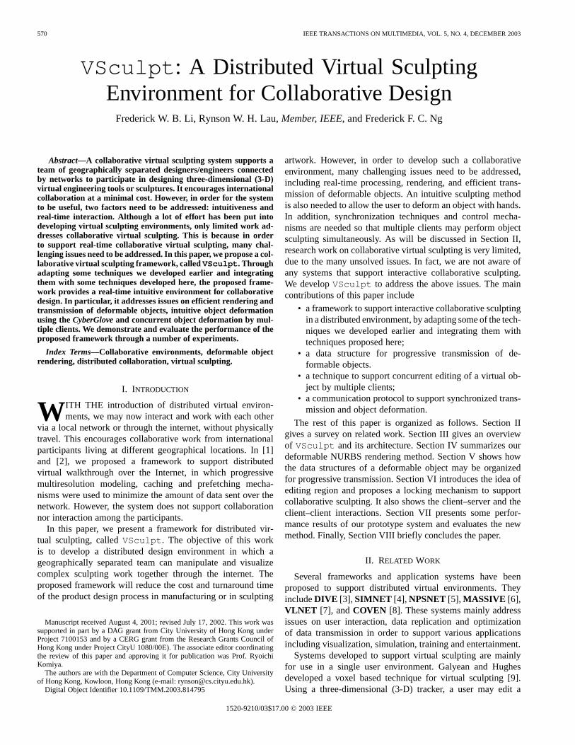
Fig. 1. Main components ofVSculpt .
needs to be refined and the refinement information is not avail-able locally, the client may either compute it locally or requestthe server for it. Details of the client–server and client–clientcommunications can be found in Sections VI-B and VI-C.
B. Architecture ofVSculpt
VSculpt is based on a hybrid model which merges theclient–server and the peer-to-peer architectures. Every par-ticipant can be a server or a client. Anobject serveris theowner of deformable objects for sculpting. It is responsiblefor constructing the NURBS stream of each object. A clientequipped with aCyberGlovemay modify the shape of an objectand broadcasts the updated control points to all the clientsincluding the object server. Fig. 1 shows the main componentsof VSculpt .
The server module consists of four main processes. TheServer Managercoordinates all other components at the serverand handles all clients’ requests and updates. TheModel Pre-processorcomputes a polygon model and a set of deformationcoefficients for each deformable object. The data are then sentto the Model Serializer, which constructs a NURBS streamfrom the polygon model and the set of deformation coefficients.The NURBS stream is then stored in the database for latertransmission to the clients upon their requests. Finally, theNetwork Agenthandles all the communications between theserver and the clients, including object requests and objectupdates.
The client also consists of four main processes. TheClientManagercoordinates all components at the client and handlesall user inputs. It is responsible for requesting the NURBSstreams from the server to construct the relevant data structuresand then passes the information to the graphics engine to bemaintained there. TheVirtual Sculpting Managergeneratesa parametric hand surface for theCyberGloveand performsvirtual sculpting based on the user’s hand gesture. The updatedcontrol points of the deforming object are then sent to thegraphics engine via the client manager. TheNetwork Agenthandles all the communications between the client and theserver, including object requests and object updates. It alsosends update messages to other clients. Finally, theGraphics
Engine is responsible for maintaining and updating all theobject models downloaded, including deformable models. Itgenerates output images for display in every frame.
IV. RENDERING OFDEFORMING OBJECTS
In our earlier work, we developed a technique for efficientrendering of deformable NURBS surfaces [16], [17]. The basicidea of this method is to maintain two data structures of eachsurface, the surface model and a polygon model representingthe surface model. As the surface deforms, the polygon model isnot regenerated through tessellation. Instead, it is incrementallyupdated to represent the deforming surface. There are two tech-niques fundamental to our method:incremental polygon modelupdatingandresolution refinement.
A. Incremental Polygon Model Updating
In this technique, we incrementally update a precomputedpolygon model to represent each deforming surface. To showhow it works, we consider the polygonal representation of a sur-face obtained by evaluating the surface equation with some dis-crete parametric values. If a control point is moved to
with a displacement vector , the incrementaldifference between the two polygonal representations of the sur-face before and after the control point movement is as follows:
(1)where and are the polygon models of the sur-face before and after the control point movement, respectively.
is called thedeformation coefficientdefined as follows:
(2)
The deformation coefficient is a constant for each par-ticular pair of . Hence, if the resolution of the polygonmodel representing the surface remains unchanged before and
LI et al.: VSculpt : DISTRIBUTED VIRTUAL SCULPTING ENVIRONMENT 573
after the deformation, we may precompute the deformation co-efficients and update the polygon model incrementally as shownin (1). This technique is very efficient since we need to performonly one vector addition and one scalar-vector multiplication oneach affected vertex of the polygon model. Another advantageis that the performance of the method is independent of the sur-face complexity.
B. Resolution Refinement
When a surface deforms, its curvature is also changed. If thecurvature is increased or decreased by a large amount during thedeformation, the resolution of the polygon model may becometoo coarse or higher than necessary to represent the deformingsurface, respectively. To overcome this problem, we proposeda resolution refinementtechnique to refine the resolution of thepolygon model and to compute new deformation coefficientsincrementally according to the change in the surface curvature.
A NURBS surface is first converted into a set of Bézierpatches using knot insertion [19]. Each Bézier patch is thensubdivided into a polygon model by applying the de Casteljausubdivision formula [20] to the Bernstein polynomials in both
and directions. For example, in, we have
(3)
where and ,. are the homogeneous Bézier
points with , are the weights, and is the degree ofthe surface. The direction has similar recursion.
If we compute the difference of (3) before and after the de-formation and then simplify it, we get a de Casteljau formula asfollows:
(4)
for , . Equation (4) indicates thatthe deformation coefficients can be generated incrementally bythe de Casteljau subdivision formula.
Hence, if the resolution of the polygon model needs to beincreased, the new deformation coefficients can be calculatedfrom adjacent deformation coefficients stored at existing ver-tices using the de Casteljau formula. To achieve a better perfor-mance, we implemented this based on the Horner’s formula, ofaverage complexity as opposed to when based onthe de Casteljau’s formula.
V. DEFORMABLE OBJECTTRANSMISSION
In our deformable NURBS rendering method, we maintain apolygon model of each deformable object in a quadtree struc-ture. The algorithms for this pointer-based tree structure are re-cursive in nature. In addition, the navigation methods associatedwith these algorithms are often restricted to preorder, inorderor postorder tree traversal. If an operation, such as the crackprevention process in our rendering method, requires informa-tion from neighboring nodes for the comparison of subdivisionlevels, an additional tree traversal operation is needed to locate
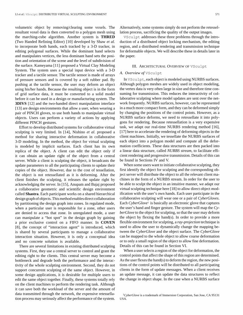
Fig. 2. Z-ordering indexing scheme.
the neighboring node starting from the root node, unless extrapointers are provided to link each node to its neighboring nodes.To overcome this limitation, we propose a new linear data struc-ture, calledNURBS streams, which are used to maintain andtransmit the precomputed polygon models of the NURBS sur-faces.
A NURBS stream is based on the linear quadtree structureproposed by [21] using the z-ordering indexing scheme [22].It allows constant navigation time between any node pairs andsupports progressive transmission. Fig. 2 illustrates the z-or-dering indexing scheme for a linear quadtree. It shows a top viewof the two possible spatial organizations of a parent nodewithits child nodes , , and . A quadtree isassumed to start from level 1, i.e., the root node. Each quadtreenode is assigned with an unique index. When assigning an indexto a node, if the child node is residing at an odd level, we applythe spatial organization shown in Fig. 2(a); otherwise, we applythe one shown in Fig. 2(b).
A. Indexing Scheme
A linear quadtree is a pointerless scheme to store a genericquadtree in the form of a linear array of nodes. The quadtreenodes are ordered by both the z-ordering indexing scheme andtheir residing quadtree levels. Each potential node, whether itexists or not, is assigned with a static and unique index. Forexample, the index of the root node is “0” and a node residing ata deeper quadtree level has a greater index value. Given a nodeof index , we can determine the following:
Parent node index (5)
Child node indices (6)
Node level (7)
Western neighbor (8)
Eastern neighbor (9)
Northern neighbor (10)
Southern neighbor (11)
where is the 2D location of the node in the grid ofnodes at a particular level. and are the precomputedlists, called distance vectors, that give the horizontal and ver-tical index differences for pairs of neighboring nodes at level,respectively.
574 IEEE TRANSACTIONS ON MULTIMEDIA, VOL. 5, NO. 4, DECEMBER 2003
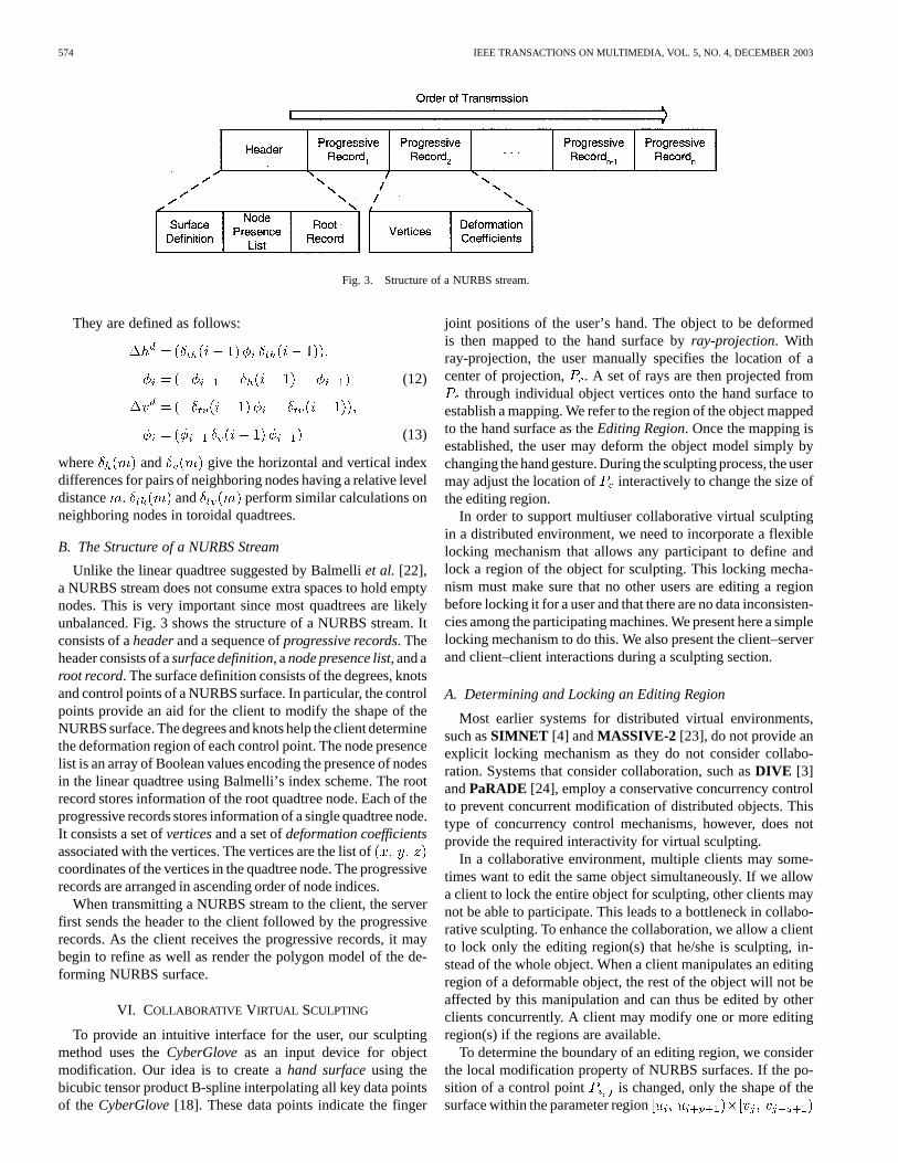
Fig. 3. Structure of a NURBS stream.
They are defined as follows:
(12)
(13)
where and give the horizontal and vertical indexdifferences for pairs of neighboring nodes having a relative leveldistance . and perform similar calculations onneighboring nodes in toroidal quadtrees.
B. The Structure of a NURBS Stream
Unlike the linear quadtree suggested by Balmelliet al. [22],a NURBS stream does not consume extra spaces to hold emptynodes. This is very important since most quadtrees are likelyunbalanced. Fig. 3 shows the structure of a NURBS stream. Itconsists of aheaderand a sequence ofprogressive records. Theheader consists of asurface definition, anode presence list, and aroot record. The surface definition consists of the degrees, knotsand control points of a NURBS surface. In particular, the controlpoints provide an aid for the client to modify the shape of theNURBS surface. The degrees and knots help the client determinethe deformation region of each control point. The node presencelist is an array of Boolean values encoding the presence of nodesin the linear quadtree using Balmelli’s index scheme. The rootrecord stores information of the root quadtree node. Each of theprogressive records stores information of a single quadtree node.It consists a set ofverticesand a set ofdeformation coefficientsassociated with the vertices. The vertices are the list ofcoordinates of the vertices in the quadtree node. The progressiverecords are arranged in ascending order of node indices.
When transmitting a NURBS stream to the client, the serverfirst sends the header to the client followed by the progressiverecords. As the client receives the progressive records, it maybegin to refine as well as render the polygon model of the de-forming NURBS surface.
VI. COLLABORATIVE VIRTUAL SCULPTING
To provide an intuitive interface for the user, our sculptingmethod uses theCyberGloveas an input device for objectmodification. Our idea is to create ahand surfaceusing thebicubic tensor product B-spline interpolating all key data pointsof the CyberGlove[18]. These data points indicate the finger
joint positions of the user’s hand. The object to be deformedis then mapped to the hand surface byray-projection. Withray-projection, the user manually specifies the location of acenter of projection, . A set of rays are then projected from
through individual object vertices onto the hand surface toestablish a mapping. We refer to the region of the object mappedto the hand surface as theEditing Region. Once the mapping isestablished, the user may deform the object model simply bychanging the hand gesture. During the sculpting process, the usermay adjust the location of interactively to change the size ofthe editing region.
In order to support multiuser collaborative virtual sculptingin a distributed environment, we need to incorporate a flexiblelocking mechanism that allows any participant to define andlock a region of the object for sculpting. This locking mecha-nism must make sure that no other users are editing a regionbefore locking it for a user and that there are no data inconsisten-cies among the participating machines. We present here a simplelocking mechanism to do this. We also present the client–serverand client–client interactions during a sculpting section.
A. Determining and Locking an Editing Region
Most earlier systems for distributed virtual environments,such asSIMNET [4] andMASSIVE-2 [23], do not provide anexplicit locking mechanism as they do not consider collabo-ration. Systems that consider collaboration, such asDIVE [3]andPaRADE [24], employ a conservative concurrency controlto prevent concurrent modification of distributed objects. Thistype of concurrency control mechanisms, however, does notprovide the required interactivity for virtual sculpting.
In a collaborative environment, multiple clients may some-times want to edit the same object simultaneously. If we allowa client to lock the entire object for sculpting, other clients maynot be able to participate. This leads to a bottleneck in collabo-rative sculpting. To enhance the collaboration, we allow a clientto lock only the editing region(s) that he/she is sculpting, in-stead of the whole object. When a client manipulates an editingregion of a deformable object, the rest of the object will not beaffected by this manipulation and can thus be edited by otherclients concurrently. A client may modify one or more editingregion(s) if the regions are available.
To determine the boundary of an editing region, we considerthe local modification property of NURBS surfaces. If the po-sition of a control point is changed, only the shape of thesurface within the parameter region
LI et al.: VSculpt : DISTRIBUTED VIRTUAL SCULPTING ENVIRONMENT 575
(a)
(b)
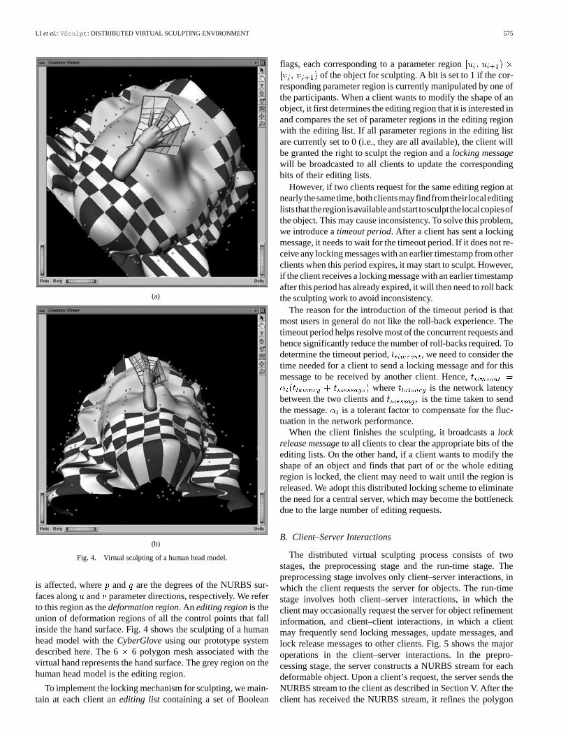
Fig. 4. Virtual sculpting of a human head model.
is affected, where and are the degrees of the NURBS sur-faces along and parameter directions, respectively. We referto this region as thedeformation region. An editing regionis theunion of deformation regions of all the control points that fallinside the hand surface. Fig. 4 shows the sculpting of a humanhead model with theCyberGloveusing our prototype systemdescribed here. The 6 6 polygon mesh associated with thevirtual hand represents the hand surface. The grey region on thehuman head model is the editing region.
To implement the locking mechanism for sculpting, we main-tain at each client anediting list containing a set of Boolean
flags, each corresponding to a parameter regionof the object for sculpting. A bit is set to 1 if the cor-
responding parameter region is currently manipulated by one ofthe participants. When a client wants to modify the shape of anobject, it first determines the editing region that it is interested inand compares the set of parameter regions in the editing regionwith the editing list. If all parameter regions in the editing listare currently set to 0 (i.e., they are all available), the client willbe granted the right to sculpt the region and alocking messagewill be broadcasted to all clients to update the correspondingbits of their editing lists.
However, if two clients request for the same editing region atnearly thesametime,bothclientsmayfindfromtheir localeditingliststhattheregionisavailableandstarttosculptthelocalcopiesofthe object. This may cause inconsistency. To solve this problem,we introduce atimeout period. After a client has sent a lockingmessage, it needs to wait for the timeout period. If it does not re-ceive any locking messages with an earlier timestamp from otherclients when this period expires, it may start to sculpt. However,if the client receives a locking message with an earlier timestampafter this period has already expired, it will then need to roll backthe sculpting work to avoid inconsistency.
The reason for the introduction of the timeout period is thatmost users in general do not like the roll-back experience. Thetimeout period helps resolve most of the concurrent requests andhence significantly reduce the number of roll-backs required. Todetermine the timeout period, , we need to consider thetime needed for a client to send a locking message and for thismessage to be received by another client. Hence,
where is the network latencybetween the two clients and is the time taken to sendthe message. is a tolerant factor to compensate for the fluc-tuation in the network performance.
When the client finishes the sculpting, it broadcasts alockrelease messageto all clients to clear the appropriate bits of theediting lists. On the other hand, if a client wants to modify theshape of an object and finds that part of or the whole editingregion is locked, the client may need to wait until the region isreleased. We adopt this distributed locking scheme to eliminatethe need for a central server, which may become the bottleneckdue to the large number of editing requests.
B. Client–Server Interactions
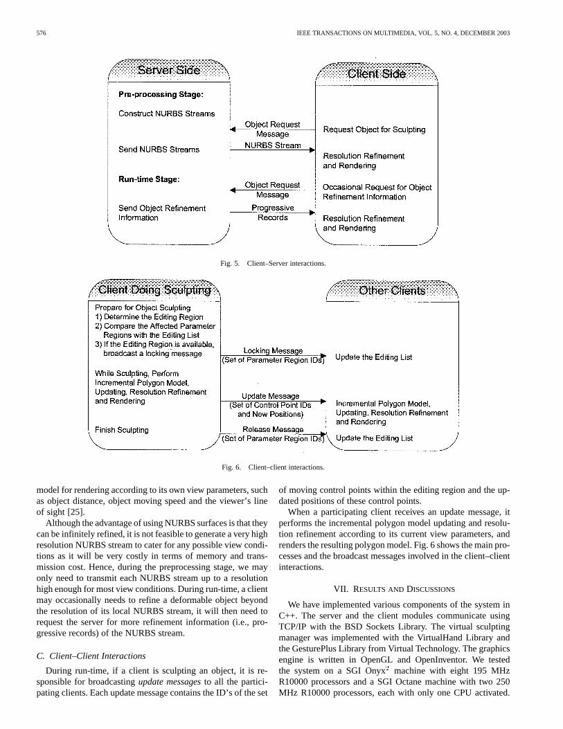
The distributed virtual sculpting process consists of twostages, the preprocessing stage and the run-time stage. Thepreprocessing stage involves only client–server interactions, inwhich the client requests the server for objects. The run-timestage involves both client–server interactions, in which theclient may occasionally request the server for object refinementinformation, and client–client interactions, in which a clientmay frequently send locking messages, update messages, andlock release messages to other clients. Fig. 5 shows the majoroperations in the client–server interactions. In the prepro-cessing stage, the server constructs a NURBS stream for eachdeformable object. Upon a client’s request, the server sends theNURBS stream to the client as described in Section V. After theclient has received the NURBS stream, it refines the polygon
576 IEEE TRANSACTIONS ON MULTIMEDIA, VOL. 5, NO. 4, DECEMBER 2003
Fig. 5. Client–Server interactions.
Fig. 6. Client–client interactions.
model for rendering according to its own view parameters, suchas object distance, object moving speed and the viewer’s lineof sight [25].
Although the advantage of using NURBS surfaces is that theycan be infinitely refined, it is not feasible to generate a very highresolution NURBS stream to cater for any possible view condi-tions as it will be very costly in terms of memory and trans-mission cost. Hence, during the preprocessing stage, we mayonly need to transmit each NURBS stream up to a resolutionhigh enough for most view conditions. During run-time, a clientmay occasionally needs to refine a deformable object beyondthe resolution of its local NURBS stream, it will then need torequest the server for more refinement information (i.e., pro-gressive records) of the NURBS stream.
C. Client–Client Interactions
During run-time, if a client is sculpting an object, it is re-sponsible for broadcastingupdate messagesto all the partici-pating clients. Each update message contains the ID’s of the set
of moving control points within the editing region and the up-dated positions of these control points.
When a participating client receives an update message, itperforms the incremental polygon model updating and resolu-tion refinement according to its current view parameters, andrenders the resulting polygon model. Fig. 6 shows the main pro-cesses and the broadcast messages involved in the client–clientinteractions.
VII. RESULTS AND DISCUSSIONS
We have implemented various components of the system inC++. The server and the client modules communicate usingTCP/IP with the BSD Sockets Library. The virtual sculptingmanager was implemented with the VirtualHand Library andthe GesturePlus Library from Virtual Technology. The graphicsengine is written in OpenGL and OpenInventor. We testedthe system on a SGI Onyxmachine with eight 195 MHzR10000 processors and a SGI Octane machine with two 250MHz R10000 processors, each with only one CPU activated.
LI et al.: VSculpt : DISTRIBUTED VIRTUAL SCULPTING ENVIRONMENT 577
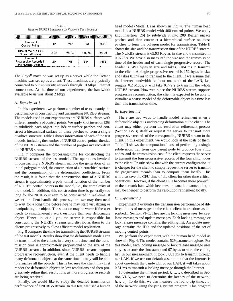
TABLE ISIZES OFNURBS STREAMS FORVARIOUS TEST MODELS
The Onyx machine was set up as a server while the Octanemachine was set up as a client. These machines are physicallyconnected to our university network through 10 Mbps Ethernetconnections. At the time of our experiments, the bandwidthavailable to us was about 2 Mbps.
A. Experiment 1
In this experiment, we perform a number of tests to study theperformance in constructing and transmitting NURBS streams.The models used in our experiments are NURBS surfaces withdifferent numbers of control points. We apply knot insertion [26]to subdivide each object into Bézier surface patches and con-struct a hierarchical surface on these patches to form a singlequadtree structure. Table I shows information of each of the testmodels, including the number of NURBS control points, the sizeof the NURBS stream and the number of progressive records inthe NURBS stream.
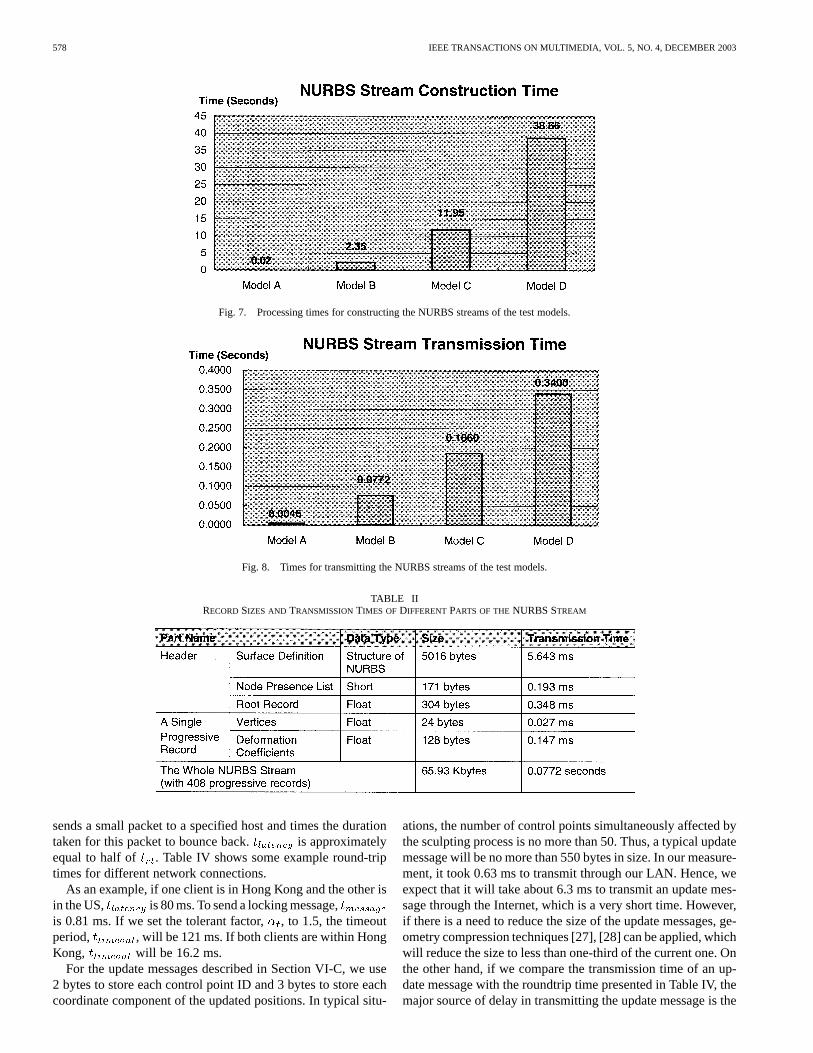
Fig. 7 compares the processing time for constructing theNURBS streams of the test models. The operations involvedin constructing a NURBS stream include the generation of aninitial polygon model, the construction of a hierarchical surfaceand the computation of the deformation coefficients. Fromthe result, it is found that the construction time of a NURBSstream is approximately a polynomial function of the numberof NURBS control points in the model, i.e., the complexity ofthe model. In addition, this construction time is generally toolong for the NURBS stream to be constructed in real-time. Ifwe let the client handle this process, the user may then needto wait for a long time before he/she may start visualizing ormanipulating the object. The situation may be worse if the userneeds to simultaneously work on more than one deformableobject. Hence, inVSculpt , the server is responsible forconstructing the NURBS streams and distributes them to theclients progressively to allow efficient model replication.
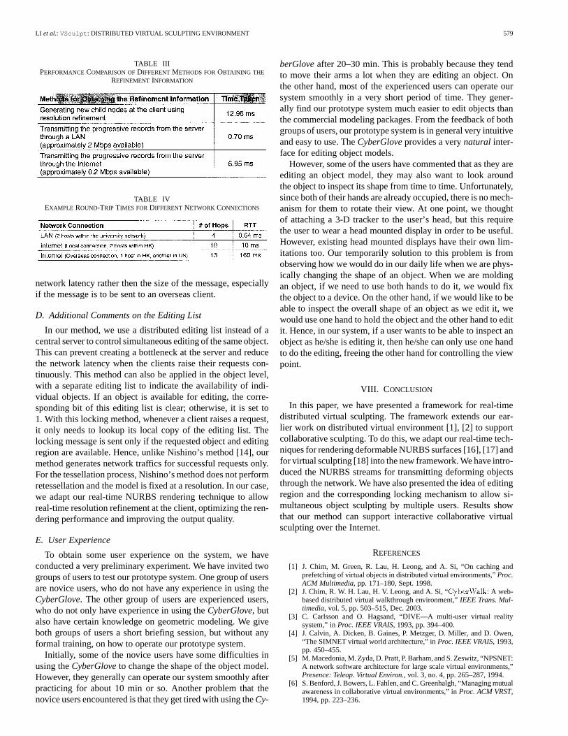
Fig. 8 compares the time for transmitting the NURBS streamsof the test models. Results show that the deformable models canbe transmitted to the clients in a very short time, and the trans-mission time is approximately proportional to the size of theNURBS streams. In addition, since NURBS streams supportprogressive reconstruction, even if the client needs to handlemany deformable objects at the same time, it may still be ableto visualize all the objects. This is because the client may firstrender the deformable objects in low resolutions and then pro-gressively refine their resolutions as more progressive recordsare being received.
Finally, we would like to study the detailed transmissionperformance of a NURBS stream. In this test, we used a human
head model (Model B) as shown in Fig. 4. The human headmodel is a NURBS model with 400 control points. We applyknot insertion [26] to subdivide it into 289 Bézier surfacepatches and then construct a hierarchical surface on thesepatches to form the polygon model for transmission. Table IIshows the size and the transmission time of the NURBS stream.The NURBS stream is 65.93 Kbytes in size and transmitted in0.0772 s. We have also measured the size and the transmissiontime of the header and of each single progressive record. Theheader is 5491 bytes in size and takes 6.184 ms to transmitto the client. A single progressive record is 152 bytes in sizeand takes 0.174 ms to transmit to the client. If we assume thatthe Internet bandwidth is about one-tenth of the LAN, i.e.,roughly 0.2 Mbps, it will take 0.772 s to transmit the wholeNURBS stream. However, since the NURBS stream supportsprogressive reconstruction, the client is expected to be able tovisualize a coarse model of the deformable object in a time lessthan this transmission time.
B. Experiment 2
There are two ways to handle model refinement when adeformable object is undergoing deformation at the client. Theclient may either perform the resolution refinement process(Section IV-B) itself or request the server to transmit moreprogressive records of the corresponding NURBS stream to theclient. In this experiment, we would look at the costs of them.Table III shows the computational cost of performing a singlesubdivision, i.e., from one parent node to produce four childnodes, and the transmission cost if the client requests the serverto transmit the four progressive records of the four child nodesto the client. Results show that with the current configuration, itis cheaper for the client to simply request the server to transmitthe progressive records than to compute them locally. Thiswill also save the CPU time of the client for other time criticaloperations. However, if the client CPU becomes more powerfulor the network bandwidth becomes too small, at some point, itmay be cheaper to perform the resolution refinement locally.
C. Experiment 3
Experiment 3 evaluates the transmission performance of dif-ferent kinds of messages in the client–client interactions as de-scribed in Section VI-C. They are the locking messages, lock re-lease messages and update messages. Each locking message orlock release message contains the editing list. An update mes-sage contains the ID’s and the updated positions of the set ofmoving control points.
We perform the experiment with the human head model asshown in Fig. 4. The model contains 529 parameter regions. Forthis model, each locking message or lock release message uses4 bytes to store the timestamp and 67 bytes to store the editinglist. In our measurement, it took 0.081 ms to transmit throughour LAN. If we use our default assumption that the Internet isabout one-tenth the bandwidth of our LAN, it will takes about0.81 ms to transmit a locking message through the Internet.
To determine the timeout period, , described in Sec-tion VI-A, we need to determine the latency of the network,
. To do this, we can measure the round-trip time,,of the network using theping system program. This program
578 IEEE TRANSACTIONS ON MULTIMEDIA, VOL. 5, NO. 4, DECEMBER 2003
Fig. 7. Processing times for constructing the NURBS streams of the test models.
Fig. 8. Times for transmitting the NURBS streams of the test models.
TABLE IIRECORDSIZES AND TRANSMISSIONTIMES OF DIFFERENTPARTS OF THENURBS STREAM
sends a small packet to a specified host and times the durationtaken for this packet to bounce back. is approximatelyequal to half of . Table IV shows some example round-triptimes for different network connections.
As an example, if one client is in Hong Kong and the other isin the US, is 80 ms. To send a locking message,is 0.81 ms. If we set the tolerant factor,, to 1.5, the timeoutperiod, , will be 121 ms. If both clients are within HongKong, will be 16.2 ms.
For the update messages described in Section VI-C, we use2 bytes to store each control point ID and 3 bytes to store eachcoordinate component of the updated positions. In typical situ-
ations, the number of control points simultaneously affected bythe sculpting process is no more than 50. Thus, a typical updatemessage will be no more than 550 bytes in size. In our measure-ment, it took 0.63 ms to transmit through our LAN. Hence, weexpect that it will take about 6.3 ms to transmit an update mes-sage through the Internet, which is a very short time. However,if there is a need to reduce the size of the update messages, ge-ometry compression techniques [27], [28] can be applied, whichwill reduce the size to less than one-third of the current one. Onthe other hand, if we compare the transmission time of an up-date message with the roundtrip time presented in Table IV, themajor source of delay in transmitting the update message is the
LI et al.: VSculpt : DISTRIBUTED VIRTUAL SCULPTING ENVIRONMENT 579
TABLE IIIPERFORMANCECOMPARISON OFDIFFERENTMETHODS FOROBTAINING THE
REFINEMENT INFORMATION
TABLE IVEXAMPLE ROUND-TRIP TIMES FORDIFFERENTNETWORK CONNECTIONS
network latency rather then the size of the message, especiallyif the message is to be sent to an overseas client.
D. Additional Comments on the Editing List
In our method, we use a distributed editing list instead of acentral server to control simultaneous editing of the same object.This can prevent creating a bottleneck at the server and reducethe network latency when the clients raise their requests con-tinuously. This method can also be applied in the object level,with a separate editing list to indicate the availability of indi-vidual objects. If an object is available for editing, the corre-sponding bit of this editing list is clear; otherwise, it is set to1. With this locking method, whenever a client raises a request,it only needs to lookup its local copy of the editing list. Thelocking message is sent only if the requested object and editingregion are available. Hence, unlike Nishino’s method [14], ourmethod generates network traffics for successful requests only.For the tessellation process, Nishino’s method does not performretessellation and the model is fixed at a resolution. In our case,we adapt our real-time NURBS rendering technique to allowreal-time resolution refinement at the client, optimizing the ren-dering performance and improving the output quality.
E. User Experience
To obtain some user experience on the system, we haveconducted a very preliminary experiment. We have invited twogroups of users to test our prototype system. One group of usersare novice users, who do not have any experience in using theCyberGlove. The other group of users are experienced users,who do not only have experience in using theCyberGlove, butalso have certain knowledge on geometric modeling. We giveboth groups of users a short briefing session, but without anyformal training, on how to operate our prototype system.
Initially, some of the novice users have some difficulties inusing theCyberGloveto change the shape of the object model.However, they generally can operate our system smoothly afterpracticing for about 10 min or so. Another problem that thenovice users encountered is that they get tired with using theCy-
berGloveafter 20–30 min. This is probably because they tendto move their arms a lot when they are editing an object. Onthe other hand, most of the experienced users can operate oursystem smoothly in a very short period of time. They gener-ally find our prototype system much easier to edit objects thanthe commercial modeling packages. From the feedback of bothgroups of users, our prototype system is in general very intuitiveand easy to use. TheCyberGloveprovides a verynatural inter-face for editing object models.
However, some of the users have commented that as they areediting an object model, they may also want to look aroundthe object to inspect its shape from time to time. Unfortunately,since both of their hands are already occupied, there is no mech-anism for them to rotate their view. At one point, we thoughtof attaching a 3-D tracker to the user’s head, but this requirethe user to wear a head mounted display in order to be useful.However, existing head mounted displays have their own lim-itations too. Our temporarily solution to this problem is fromobserving how we would do in our daily life when we are phys-ically changing the shape of an object. When we are moldingan object, if we need to use both hands to do it, we would fixthe object to a device. On the other hand, if we would like to beable to inspect the overall shape of an object as we edit it, wewould use one hand to hold the object and the other hand to editit. Hence, in our system, if a user wants to be able to inspect anobject as he/she is editing it, then he/she can only use one handto do the editing, freeing the other hand for controlling the viewpoint.
VIII. C ONCLUSION
In this paper, we have presented a framework for real-timedistributed virtual sculpting. The framework extends our ear-lier work on distributed virtual environment [1], [2] to supportcollaborative sculpting. To do this, we adapt our real-time tech-niques for rendering deformable NURBS surfaces [16], [17] andfor virtual sculpting [18] into the new framework. We have intro-duced the NURBS streams for transmitting deforming objectsthrough the network. We have also presented the idea of editingregion and the corresponding locking mechanism to allow si-multaneous object sculpting by multiple users. Results showthat our method can support interactive collaborative virtualsculpting over the Internet.
REFERENCES
[1] J. Chim, M. Green, R. Lau, H. Leong, and A. Si, “On caching andprefetching of virtual objects in distributed virtual environments,”Proc.ACM Multimedia, pp. 171–180, Sept. 1998.
[2] J. Chim, R. W. H. Lau, H. V. Leong, and A. Si, “CyberWalk: A web-based distributed virtual walkthrough environment,”IEEE Trans. Mul-timedia, vol. 5, pp. 503–515, Dec. 2003.
[3] C. Carlsson and O. Hagsand, “DIVE—A multi-user virtual realitysystem,” inProc. IEEE VRAIS, 1993, pp. 394–400.
[4] J. Calvin, A. Dicken, B. Gaines, P. Metzger, D. Miller, and D. Owen,“The SIMNET virtual world architecture,” inProc. IEEE VRAIS, 1993,pp. 450–455.
[5] M. Macedonia, M. Zyda, D. Pratt, P. Barham, and S. Zeswitz, “NPSNET:A network software architecture for large scale virtual environments,”Presence: Teleop. Virtual Environ., vol. 3, no. 4, pp. 265–287, 1994.
[6] S. Benford, J. Bowers, L. Fahlen, and C. Greenhalgh, “Managing mutualawareness in collaborative virtual environments,” inProc. ACM VRST,1994, pp. 223–236.
580 IEEE TRANSACTIONS ON MULTIMEDIA, VOL. 5, NO. 4, DECEMBER 2003
[7] I. Pandzic, T. Capin, E. Lee, N. Thalmann, and D. Thalmann, “A flexiblearchitecture for virtual humans in networked collaborative virtual envi-ronments,” inProc. Eurographics’97, vol. 16, Sept. 1997, pp. 177–188.
[8] C. Babskiet al., “The COVEN Project: Exploring applicative, technicaland usage dimensions of collaborative virtual environments,”Presence:Teleop. Virtual Environ., vol. 8, no. 2, pp. 218–236, 1999.
[9] T. Galyean and J. Hughes, “Sculpting: An interactive volumetricmodeling technique,” inProc. ACM SIGGRAPH’91, vol. 25, 1991, pp.267–274.
[10] C. Shaw and M. Green, “THRED: A two-handed design system,”Mul-timedia Syst. J., vol. 5, pp. 126–139, Mar. 1997.
[11] K. Kameyama, “Virtual clay modeling system,” inProc. ACM VRST,Sept. 1997, pp. 197–200.
[12] F. Kuester, M. Duchaineau, B. Hamann, K. Joy, and A. Uva, “3DIVS:3-dimensional immersive virtual sculpting,” inProc. Workshop on NewParadigms in Information Visualization and Manipulation, Nov. 1999,pp. 92–96.
[13] L. Cutler, B. Fröhlich, and P. Hanrahan, “Two-handed direct manipula-tion on the responsive workbench,” inProc. ACM Symp. Interactive 3DGraphics, Apr. 1997, pp. 107–114.
[14] H. Nishino, K. Utsumiya, A. Sakamoto, K. Yoshida, and K. Korida, “Amethod for sharing interactive deformations in collaborative 3D mod-eling,” in Proc. ACM VRST, Dec. 1999, pp. 116–123.
[15] V. Anupam and C. Bajaj, “Shastra: Multimedia collaborative design en-vironment,”IEEE Multimedia, vol. 1, no. 2, pp. 39–49, 1994.
[16] F. Li, R. Lau, and M. Green, “Interactive rendering of deformingNURBS surfaces,” inProc. Eurographics’97, vol. 16, Sept. 1997, pp.47–56.
[17] F. Li and R. Lau, “Incremental polygonization of deforming NURBSsurfaces,”J. Graph. Tools, vol. 4, no. 4, pp. 37–50, 1999.
[18] J. Wong, R. Lau, and L. Ma, “Virtual 3D sculpting,”J. VisualizationComput. Animation, vol. 11, no. 3, pp. 155–166, 2000.
[19] E. Cohen, T. Lyche, and R. Riesenfeld, “Discrete B-splines and sub-division techniques in computer-aided geometric design and computergraphics,”Comput. Graph. Image Process., vol. 14, Oct. 1980.
[20] P. de Casteljau, “Courbes et surfaces à pôles,”S. A. André Citroen, 1959.[21] I. Gargantini, “An effective way to represent quadtrees,”Commun.
ACM, vol. 25, pp. 905–910, Dec. 1982.[22] L. Balmelli, J. Kovacevic, and M. Vetterli, “Quadtrees for embedded
surface visualization: Constraints and efficient data structures,” inProc.IEEE ICIP, vol. 2, Oct. 1999, pp. 487–491.
[23] C. Greenhalgh and S. Benford, “A multicast network architecture forlarge scale collaborative virtual environments,” inProc. . Eur. Conf.Multimedia Applications, Services and Techniques (ECMAST ’97), May1997, pp. 113–128.
[24] D. Roberts and P. Sharkey, “Maximizing concurrency and scalability ina consistent, causal, distributed virtual reality system, whilst minimizingthe effect of network delays,” inProc. IEEE Workshop on EnablingTechnology: Infrastructure for Collaborative Enterprise (WETICE ’97),1997, pp. 161–166.
[25] R. Lau, D. To, and M. Green, “An adaptive multi-resolution modelingtechnique based on viewing and animation parameters,”Proc. IEEEVRAIS, pp. 20–27, 1997.
[26] L. Piegl and W. Tiller,The NURBS Book. Berlin, Germany: Springer-Verlag, 1995.
[27] P. Alliez and M. Desbrun, “Progressive compression for lossless trans-mission of triangle meshes,” inProc. ACM SIGGRAPH’01, Aug. 2001,pp. 195–202.
[28] A. Khodakovsky, P. Schröder, and W. Sweldens, “Progressive geometrycompression,” inProc. ACM SIGGRAPH’00, July 2000, pp. 271–278.
Frederick W. B. Li received both the B.A. (Honors)in Computing Studies and M.Phil. degrees fromthe Hong Kong Polytechnic University in 1994 and1998, respectively, and the Ph.D. degree in computergraphics from the City University of Hong Kong in2001.
He is currently the Research Manager of the“Web-based 3D collaborative engine” project fundedby the Hong Kong Government Innovation andTechnology Fund, Pacific Century CyberWorks(PCCW), and Sun Microsystems. His research
interests include surface modeling, virtual reality, computer animation andcomputer networking.
Rynson W. H. Lau (M’88) received a (top) first classhonors degree in computer systems engineering in1988 from the University of Kent, Canterbury, U.K.,and the Ph.D. degree in computer graphics in 1992from the University of Cambridge, U.K.
He is currently an Associate Professor at the CityUniversity of Hong Kong. Prior to joining the uni-versity in 1998, he taught at the Hong Kong Poly-technic University. From 1992 to 1993, he worked atthe University of York, U.K., on a defense project onimage processing. His research interests are in com-
puter graphics, virtual reality and multimedia systems.Dr. Lau is a member of the IEEE Computer Society and the ACM.
Frederick F. C. Ng received the B.A. degree(Honors) in computing studies from the Hong KongPolytechnic University in 1998.
He is currently a Research Student with theComputer Science Department, City University ofHong Kong. His research interests include computergraphics and distributed virtual environments.