Embed Size (px)
DESCRIPTION
VMware vsan
Citation preview
VMware® Virtual SAN™ Design and Sizing GuideT E C H N I C A L M A R K E T I N G D O C U M E N TAT I O NV 1 . 0 / M A R C H 2 0 1 4
VMware Virtual SAN Design and Sizing Guide
T E C H N I C A L W H I T E P A P E R / 2
Table of Contents
Introduction . . . . . . . . . . . . . . . . . . . . . . . . . . . . . . . . . . . . . . . . . . . . . . . . . . . . . . . . . . . . . . . . . . 3
1.1 VMware Virtual SAN . . . . . . . . . . . . . . . . . . . . . . . . . . . . . . . . . . . . . . . . . . . . . . . . . . . . . . .3
1.2 Virtual SAN Datastore Characteristics and Sizing . . . . . . . . . . . . . . . . . . . . . . . . . . . . .3
1.2.1 Disk Groups . . . . . . . . . . . . . . . . . . . . . . . . . . . . . . . . . . . . . . . . . . . . . . . . . . . . . . . . . .3
1.2.2 Virtual SAN Datastore . . . . . . . . . . . . . . . . . . . . . . . . . . . . . . . . . . . . . . . . . . . . . . . . .4
1.2.3 Objects and Components . . . . . . . . . . . . . . . . . . . . . . . . . . . . . . . . . . . . . . . . . . . . . .4
1.3 Virtual SAN Datastore Sizing Considerations . . . . . . . . . . . . . . . . . . . . . . . . . . . . . . . . .5
1.3.1 Number of Failures to Tolerate . . . . . . . . . . . . . . . . . . . . . . . . . . . . . . . . . . . . . . . . .5
1.4 Design Considerations . . . . . . . . . . . . . . . . . . . . . . . . . . . . . . . . . . . . . . . . . . . . . . . . . . . . .6
1.4.1 Multiple Disk Groups . . . . . . . . . . . . . . . . . . . . . . . . . . . . . . . . . . . . . . . . . . . . . . . . . . .6
1.4.2 Flash Capacity Sizing . . . . . . . . . . . . . . . . . . . . . . . . . . . . . . . . . . . . . . . . . . . . . . . . . .6
1.4.3 Memory and CPU . . . . . . . . . . . . . . . . . . . . . . . . . . . . . . . . . . . . . . . . . . . . . . . . . . . . . 7
1.4.4 Network . . . . . . . . . . . . . . . . . . . . . . . . . . . . . . . . . . . . . . . . . . . . . . . . . . . . . . . . . . . . . . 7
1.4.5 Installation Media . . . . . . . . . . . . . . . . . . . . . . . . . . . . . . . . . . . . . . . . . . . . . . . . . . . . .8
1.5 Size-Calculating Formulas . . . . . . . . . . . . . . . . . . . . . . . . . . . . . . . . . . . . . . . . . . . . . . . . . .9
1.5.1 Cluster Capacity . . . . . . . . . . . . . . . . . . . . . . . . . . . . . . . . . . . . . . . . . . . . . . . . . . . . . .9
1.5.2 Objects . . . . . . . . . . . . . . . . . . . . . . . . . . . . . . . . . . . . . . . . . . . . . . . . . . . . . . . . . . . . . .9
1.5.3 Components . . . . . . . . . . . . . . . . . . . . . . . . . . . . . . . . . . . . . . . . . . . . . . . . . . . . . . . . . .9
1.5.4 Swap . . . . . . . . . . . . . . . . . . . . . . . . . . . . . . . . . . . . . . . . . . . . . . . . . . . . . . . . . . . . . . . .10
1.5.5 Usable Capacity . . . . . . . . . . . . . . . . . . . . . . . . . . . . . . . . . . . . . . . . . . . . . . . . . . . . . .10
Conclusion . . . . . . . . . . . . . . . . . . . . . . . . . . . . . . . . . . . . . . . . . . . . . . . . . . . . . . . . . . . . . . . . . . 11
Acknowledgments . . . . . . . . . . . . . . . . . . . . . . . . . . . . . . . . . . . . . . . . . . . . . . . . . . . . . . . . . . . . 11
About the Author . . . . . . . . . . . . . . . . . . . . . . . . . . . . . . . . . . . . . . . . . . . . . . . . . . . . . . . . . . . . 11
T E C H N I C A L W H I T E P A P E R / 3
VMware Virtual SAN Design and Sizing Guide
Introduction1.1 VMware Virtual SANVMware® Virtual SAN™ is a new hypervisor-converged, software-defined storage platform that is fully integrated with VMware vSphere®. Virtual SAN aggregates locally attached disks of hosts that are members of a vSphere cluster, to create a distributed shared storage solution. Virtual SAN enables the rapid provisioning of storage within VMware vCenter™ as part of virtual machine creation and deployment operations.
Virtual SAN is a hybrid disk system that leverages both flash-based devices, to provide optimal performance, and magnetic disks, to provide capacity and persistent data storage. This delivers enterprise performance and a resilient storage platform.
The distributed datastore of Virtual SAN is an object-store file system that leverages the vSphere Storage Policy Based Management (SPBM) framework to deliver application-centric storage services and capabilities that are centrally managed through vSphere virtual machine storage policies.
This document focuses on the definitions, sizing guidelines, and characteristics of the Virtual SAN distributed datastore.
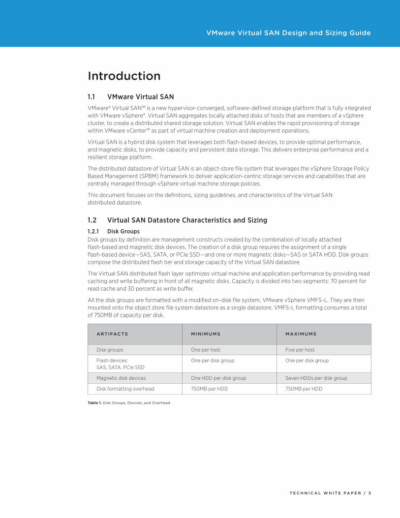
1.2 Virtual SAN Datastore Characteristics and Sizing1.2.1 Disk GroupsDisk groups by definition are management constructs created by the combination of locally attached flash-based and magnetic disk devices. The creation of a disk group requires the assignment of a single flash-based device—SAS, SATA, or PCIe SSD—and one or more magnetic disks—SAS or SATA HDD. Disk groups compose the distributed flash tier and storage capacity of the Virtual SAN datastore.
The Virtual SAN distributed flash layer optimizes virtual machine and application performance by providing read caching and write buffering in front of all magnetic disks. Capacity is divided into two segments: 70 percent for read cache and 30 percent as write buffer.
All the disk groups are formatted with a modified on-disk file system, VMware vSphere VMFS-L. They are then mounted onto the object store file system datastore as a single datastore. VMFS-L formatting consumes a total of 750MB of capacity per disk.
ARTIFACTS MINIMUMS MAXIMUMS
Disk groups One per host Five per host
Flash devices: SAS, SATA, PCIe SSD
One per disk group One per disk group
Magnetic disk devices One HDD per disk group Seven HDDs per disk group
Disk formatting overhead 750MB per HDD 750MB per HDD
Table 1. Disk Groups, Devices, and Overhead
T E C H N I C A L W H I T E P A P E R / 4
VMware Virtual SAN Design and Sizing Guide
1.2.2 Virtual SAN DatastoreThe Virtual SAN distributed datastore capacity is determined by aggregating the disk groups situated across multiple hosts that are members of a vSphere cluster and by the size of the magnetic disks. Disk groups consist of a combination of flash-based devices and magnetic disks pooled together, but only the usable capacity of the magnetic disks counts toward the total capacity of the Virtual SAN datastore. The capacity of the flash-based devices is specifically dedicated to the caching layer of Virtual SAN.
1.2.3 Objects and Components
Objects
In Virtual SAN, an object is defined based on an individual storage block device that is compatible with SCSI semantics. Conceptually, an object can also be thought of as “volumes,” the term used in Amazon EC2 and OpenStack. In Virtual SAN, the only supported objects are virtual machine files such as VMDKs.
In Virtual SAN, each object that resides on the Virtual SAN datastore comprises multiple components, which are distributed across hosts that are members of a vSphere cluster. Objects are assigned storage performance and availability services requirements through the virtual machine storage policies feature. Based on applying defined performance and availability requirements to ones specific to each object, components are distributed throughout a vSphere cluster onto physical disk devices.
OBJECT TYPES DEFINITIONS
VM home Location where all virtual machine configuration files reside: .vmx, log files, and others
Swap Unique storage object created only when virtual machines are powered on
VMDK Virtual machine disk files
Delta/Snapshot Unique storage object created only for virtual machine snapshots
Table 2. Virtual SAN Objects and Definitions
Components
In Virtual SAN, objects comprise components that are distributed across hosts in a vSphere cluster. These components are stored in distinctive combinations of disk groups within the Virtual SAN distributed datastore. Components are transparently assigned caching and buffering capacity from flash-based devices, with their data “at rest” on the magnetic disks. Virtual SAN 5.5 currently supports a maximum of 3,000 components per host.
Objects greater than 255GB in capacity automatically are divided into multiple components. In addition, if the number-of-disk-stripes-per-object capability is increased beyond the default value of one, each stripe is a separate component. For every component created in Virtual SAN, an additional 2MB of disk capacity is consumed for metadata.
Witness components—those that contain only object metadata—are part of every storage object. A witness serves as a tiebreaker, to avoid split-brain behavior when availability decisions are made in the Virtual SAN cluster. Each Virtual SAN witness component also consumes 2MB of capacity.
T E C H N I C A L W H I T E P A P E R / 5
VMware Virtual SAN Design and Sizing Guide
1.3 Virtual SAN Datastore Sizing ConsiderationsThe Virtual SAN storage solution is designed to deliver capacity, availability, and performance capabilities to virtual machines. Users must understand how these storage capabilities affect consumption of storage capacity in Virtual SAN. The number-of-failures-to-tolerate capability has the biggest impact.
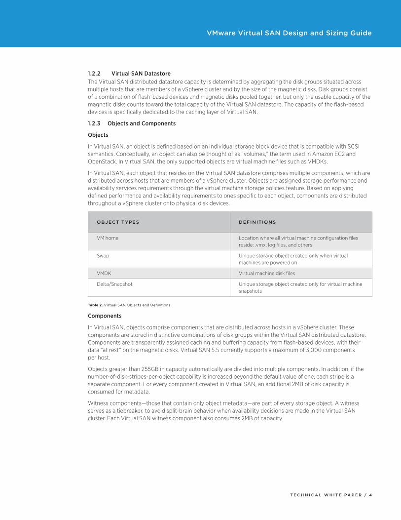
1.3.1 Number of Failures to TolerateThe number-of-failures-to-tolerate policy setting is an availability capability that can be applied to all virtual machines or individual VMDKs. This policy plays an important role when planning and sizing storage capacity for Virtual SAN. Based on the availability requirements of a virtual machine, the setting defined in a virtual machine storage policy can lead to the consumption of as many as four times the capacity of the virtual machine or individual disks.
For example, if the number of failures to tolerate is set to 1, two replica mirror copies of the virtual machine or individual VMDKs are created across the cluster. If the number is set to 2, three mirror copies are created; if the number is set to 3, four copies are created. Figures 1 through 4 illustrate the layout of the virtual machine objects, based on the number of failures to tolerate.
Figure 1. Number of Failures to Tolerate 1 = 2 Full Copies of Data + 1 Witness
Figure 2. Number of Failures to Tolerate 2 = 3 Full Copies of Data + 2 Witnesses
T E C H N I C A L W H I T E P A P E R / 6
VMware Virtual SAN Design and Sizing Guide
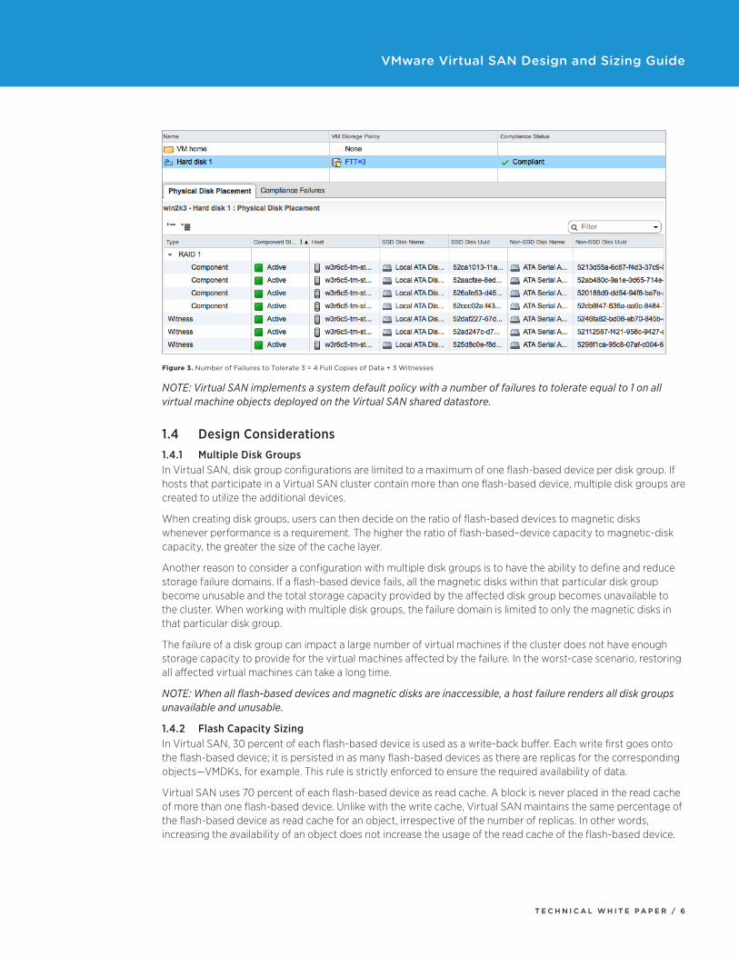
Figure 3. Number of Failures to Tolerate 3 = 4 Full Copies of Data + 3 Witnesses
NOTE: Virtual SAN implements a system default policy with a number of failures to tolerate equal to 1 on all virtual machine objects deployed on the Virtual SAN shared datastore.
1.4 Design Considerations1.4.1 Multiple Disk GroupsIn Virtual SAN, disk group configurations are limited to a maximum of one flash-based device per disk group. If hosts that participate in a Virtual SAN cluster contain more than one flash-based device, multiple disk groups are created to utilize the additional devices.
When creating disk groups, users can then decide on the ratio of flash-based devices to magnetic disks whenever performance is a requirement. The higher the ratio of flash-based–device capacity to magnetic-disk capacity, the greater the size of the cache layer.
Another reason to consider a configuration with multiple disk groups is to have the ability to define and reduce storage failure domains. If a flash-based device fails, all the magnetic disks within that particular disk group become unusable and the total storage capacity provided by the affected disk group becomes unavailable to the cluster. When working with multiple disk groups, the failure domain is limited to only the magnetic disks in that particular disk group.
The failure of a disk group can impact a large number of virtual machines if the cluster does not have enough storage capacity to provide for the virtual machines affected by the failure. In the worst-case scenario, restoring all affected virtual machines can take a long time.
NOTE: When all flash-based devices and magnetic disks are inaccessible, a host failure renders all disk groups unavailable and unusable.
1.4.2 Flash Capacity SizingIn Virtual SAN, 30 percent of each flash-based device is used as a write-back buffer. Each write first goes onto the flash-based device; it is persisted in as many flash-based devices as there are replicas for the corresponding objects—VMDKs, for example. This rule is strictly enforced to ensure the required availability of data.
Virtual SAN uses 70 percent of each flash-based device as read cache. A block is never placed in the read cache of more than one flash-based device. Unlike with the write cache, Virtual SAN maintains the same percentage of the flash-based device as read cache for an object, irrespective of the number of replicas. In other words, increasing the availability of an object does not increase the usage of the read cache of the flash-based device.
T E C H N I C A L W H I T E P A P E R / 7
VMware Virtual SAN Design and Sizing Guide
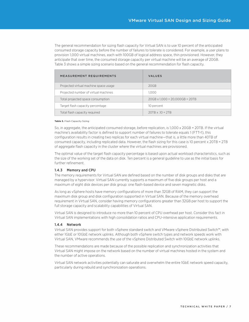
The general recommendation for sizing flash capacity for Virtual SAN is to use 10 percent of the anticipated consumed storage capacity before the number of failures to tolerate is considered. For example, a user plans to provision 1,000 virtual machines, each with 100GB of logical address space, thin provisioned. However, they anticipate that over time, the consumed storage capacity per virtual machine will be an average of 20GB. Table 3 shows a simple sizing scenario based on the general recommendation for flash capacity.
MEASUREMENT REQUIREMENTS VALUES
Projected virtual machine space usage 20GB
Projected number of virtual machines 1,000
Total projected space consumption 20GB x 1,000 = 20,000GB = 20TB
Target flash capacity percentage 10 percent
Total flash capacity required 20TB x .10 = 2TB
Table 3. Flash Capacity Sizing
So, in aggregate, the anticipated consumed storage, before replication, is 1,000 x 20GB = 20TB. If the virtual machine’s availability factor is defined to support number of failures to tolerate equals 1 (FTT=1), this configuration results in creating two replicas for each virtual machine—that is, a little more than 40TB of consumed capacity, including replicated data. However, the flash sizing for this case is 10 percent x 20TB = 2TB of aggregate flash capacity in the cluster where the virtual machines are provisioned.
The optimal value of the target flash capacity percentage is based upon actual workload characteristics, such as the size of the working set of the data on disk. Ten percent is a general guideline to use as the initial basis for further refinement.
1.4.3 Memory and CPUThe memory requirements for Virtual SAN are defined based on the number of disk groups and disks that are managed by a hypervisor. Virtual SAN currently supports a maximum of five disk groups per host and a maximum of eight disk devices per disk group: one flash-based device and seven magnetic disks.
As long as vSphere hosts have memory configurations of more than 32GB of RAM, they can support the maximum disk group and disk configuration supported in Virtual SAN. Because of the memory overhead requirement in Virtual SAN, consider having memory configurations greater than 32GB per host to support the full storage capacity and scalability capabilities of Virtual SAN.
Virtual SAN is designed to introduce no more than 10 percent of CPU overhead per host. Consider this fact in Virtual SAN implementations with high consolidation ratios and CPU-intensive application requirements.
1.4.4 NetworkVirtual SAN provides support for both vSphere standard switch and VMware vSphere Distributed Switch™, with either 1GbE or 10GbE network uplinks. Although both vSphere switch types and network speeds work with Virtual SAN, VMware recommends the use of the vSphere Distributed Switch with 10GbE network uplinks.
These recommendations are made because of the possible replication and synchronization activities that Virtual SAN might impose on the network based on the number of virtual machines hosted in the system and the number of active operations.
Virtual SAN network activities potentially can saturate and overwhelm the entire 1GbE network speed capacity, particularly during rebuild and synchronization operations.
T E C H N I C A L W H I T E P A P E R / 8
VMware Virtual SAN Design and Sizing Guide
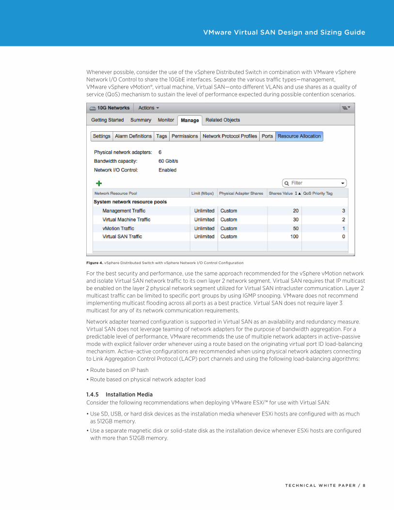
Whenever possible, consider the use of the vSphere Distributed Switch in combination with VMware vSphere Network I/O Control to share the 10GbE interfaces. Separate the various traffic types—management, VMware vSphere vMotion®, virtual machine, Virtual SAN—onto different VLANs and use shares as a quality of service (QoS) mechanism to sustain the level of performance expected during possible contention scenarios.
Figure 4. vSphere Distributed Switch with vSphere Network I/O Control Configuration
For the best security and performance, use the same approach recommended for the vSphere vMotion network and isolate Virtual SAN network traffic to its own layer 2 network segment. Virtual SAN requires that IP multicast be enabled on the layer 2 physical network segment utilized for Virtual SAN intracluster communication. Layer 2 multicast traffic can be limited to specific port groups by using IGMP snooping. VMware does not recommend implementing multicast flooding across all ports as a best practice. Virtual SAN does not require layer 3 multicast for any of its network communication requirements.
Network adapter teamed configuration is supported in Virtual SAN as an availability and redundancy measure. Virtual SAN does not leverage teaming of network adapters for the purpose of bandwidth aggregation. For a predictable level of performance, VMware recommends the use of multiple network adapters in active–passive mode with explicit failover order whenever using a route based on the originating virtual port ID load-balancing mechanism. Active–active configurations are recommended when using physical network adapters connecting to Link Aggregation Control Protocol (LACP) port channels and using the following load-balancing algorithms:
•RoutebasedonIPhash
•Routebasedonphysicalnetworkadapterload
1.4.5 Installation MediaConsider the following recommendations when deploying VMware ESXi™ for use with Virtual SAN:
•UseSD,USB,orharddiskdevicesastheinstallationmediawheneverESXihostsareconfiguredwithasmuchas 512GB memory.
•Useaseparatemagneticdiskorsolid-statediskastheinstallationdevicewheneverESXihostsareconfiguredwith more than 512GB memory.
T E C H N I C A L W H I T E P A P E R / 9
VMware Virtual SAN Design and Sizing Guide
1.5 Size-Calculating FormulasSizing for Virtual SAN can be approached in several ways. In this section, we will start with a given hardware configuration; after taking into account certain policy settings, we will then ascertain how much actual space is available for virtual machines. This is useful when determining how much usable capacity is available in a preconfigured Virtual SAN cluster.
The following scenario lists the assumptions that will be used as the basis for all of the sizing calculations in this section:
•Numberofhostspercluster(Hst) = 8
•Numberofdiskgroups(DskGrp) = 5
•Numberofdisksperdiskgroup(DskPerDskGrp) = 7
•Sizeofdisks(SzHDD) = 4,000GB
•Numberoffailurestotolerate(ftt) = 1
•Numberofvirtualmachines(VMs) = 800
•Numberofdiskspervirtualmachine(NumOfVMDK) = 1
•Memorypervirtualmachine(vmSwp) = 10GB
1.5.1 Cluster CapacityVirtual SAN raw storage capacity calculations can be performed using the following formula:
•Formula: Hst x NumDskGrpPerHst x NumDskPerDskGrp x SzHDD = y
•Example: 8 x 5 x 7 x 4,000GB = 1,120,000GB = 1,120TB
1.5.2 ObjectsThe number of objects is based on the virtual machine files, which include virtual machine home, virtual machine swap file, VMDKs, and snapshots.
•Formula: VMs x [VMnamespace + vmSwap + NumOfVMDK] = y
•Example: 800 x [1 + 1 + 1] = 2,400 Objects
NOTE: Snapshots count as individual objects in Virtual SAN. In this scenario, however, virtual machines were not identified as using snapshots; therefore, snapshots are calculated as part of the equation.
1.5.3 ComponentsThe number of objects per virtual machine, in addition to their performance and availability requirements, dictates the number of components that will be created. As mentioned earlier, Virtual SAN currently supports a maximum of 3,000 components per host. The following formula can be used to calculate the number of components per virtual machine. It accounts for the replicas and witnesses created based on the Failures to Tolerate setting. The resulting number of components is nominally split across all the hosts in the cluster.
•Formula: Object x [ftt x 2 + 1] = y
•Example: 2,400 x (1 x 2 + 1) = 7,200 components = average 900 components per host
NOTE: If the number-of-disk-stripes-per-object capability is increased beyond the default value of 1, each stripe is a separate component. In this scenario, however, the number of disk stripes is kept at the default value of 1, so it does not affect the calculation.
T E C H N I C A L W H I T E P A P E R / 1 0
VMware Virtual SAN Design and Sizing Guide
1.5.4 SwapA certain amount of raw capacity will be consumed by virtual machine swap space. Virtual SAN always stores swap space with two replicas, regardless of the Failures to Tolerate setting:
•Formula: ClusterCapacity – (VMs x vmSwp x 2)
•Example: 1,120,000GB – (800 x 10GB x 2) = 1,120,000 – 16,000 = 1,104,000GB Disk Capacity
1.5.5 Usable CapacityVirtual SAN usable capacity is the amount of capacity that can be used to store the VMDK files of all virtual machines. It is determined by subtracting the Virtual SAN overhead from the disk capacity and then dividing the remaining amount by the number of failures to tolerate plus 1:
•Formula: (DiskCapacity – DskGrp x DskPerDskGrp x Hst x VSANoverhead )/(ftt+1)
•Example: (1,104,000GB – 280GB)/(ftt+1) = 1,103,720GB/(2) = 551,860GB Usable Capacity
NOTE: As a general guideline, 1GB of storage capacity per disk will be calculated as the combination of Virtual SAN components and VMFS metadata overheard (VSANoverhead).
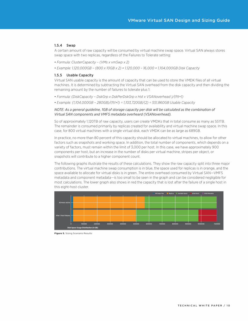
So of approximately 1,120TB of raw capacity, users can create VMDKs that in total consume as many as 551TB. The remainder is consumed primarily by replicas created for availability and virtual machine swap space. In this case, for 800 virtual machines with a single virtual disk, each VMDK can be as large as 689GB.
In practice, no more than 80 percent of this capacity should be allocated to virtual machines, to allow for other factors such as snapshots and working space. In addition, the total number of components, which depends on a variety of factors, must remain within the limit of 3,000 per host. In this case, we have approximately 900 components per host, but an increase in the number of disks per virtual machine, stripes per object, or snapshots will contribute to a higher component count.
The following graphs illustrate the results of these calculations. They show the raw capacity split into three major contributions. The virtual machine swap consumption is in blue, the space used for replicas is in orange, and the space available to allocate for virtual disks is in green. The entire overhead consumed by Virtual SAN—VMFS metadata and component metadata—is too small to be seen in the graph and can be considered negligible for most calculations. The lower graph also shows in red the capacity that is lost after the failure of a single host in this eight-host cluster.
All Hosts Active
After 1 Host Failures
0 100000 200000 300000 400000 500000 600000 700000 800000 900000 1000000 1120000
VM Swap Files
Disk Space Usage Distribution (in GB)
Replicas Available Space failed Hosts VSAN Metadata
Figure 5. Sizing Scenario Results
T E C H N I C A L W H I T E P A P E R / 1 1
VMware Virtual SAN Design and Sizing Guide
ConclusionVMware Virtual SAN is a hypervisor-converged platform that delivers a shared datastore by combining compute and storage resources of VMware vSphere hosts in a vSphere cluster while providing a much simpler storage management experience for the user. It is a storage solution designed by VMware to make software-defined storage a reality for its customers. Because certain factors must be taken into account when sizing and designing a Virtual SAN cluster, this paper has presented much of what must be considered to successfully deploy a Virtual SAN configuration.
AcknowledgmentsI would like to thank Jorge Guerra, Christian Dickmann, and Christos Karamanolis of VMware R&D, whose deep knowledge and understanding of Virtual SAN was leveraged throughout this paper. I would also like to thank Charu Chaubal, group manager of the Storage and Availability Technical Marketing team; Kiran Madnani, senior product line manager of storage technologies products; and Wade Holmes, senior technical marketing architect within the Storage and Availability Technical Marketing team, for their contributions and for reviewing this paper.
About the Author Rawlinson Rivera is a senior architect in the Cloud Infrastructure Technical Marketing group at VMware. His focus is on storage virtualization, software-defined storage technologies, and integration aspects of VMware products and solutions with the OpenStack framework. Previously he was an architect in the VMware Cloud Infrastructure and Management Professional Services organization, focused on vSphere and cloud enterprise architectures for VMware Fortune 100 and 500 customers.
Rawlinson is among the first VMware Certified Design Experts (VCDX#86) and is the author of multiple books based on VMware and other technologies.
Follow Rawlinson’s blogs:
•http://blogs.vmware.com/vsphere/storage
•http://www.punchingclouds.com
Follow Rawlinson on Twitter:
•@PunchingClouds

VMware, Inc. 3401 Hillview Avenue Palo Alto CA 94304 USA Tel 877-486-9273 Fax 650-427-5001 www .vmware .comCopyright © 2014 VMware, Inc . All rights reserved . This product is protected by U .S . and international copyright and intellectual property laws . VMware products are covered by one or more patents listed at http://www .vmware .com/go/patents . VMware is a registered trademark or trademark of VMware, Inc . in the United States and/or other jurisdictions . All other marks and names mentioned herein may be trademarks of their respective companies . Item No: VMW-TMD-VSAN-Dsgn-Szng-Guide-USLET-101 Docsource: OIC - 14VM004 .11


![Oracle VM Server for SPARC 3.3 Reference Manual · ldm set-vhba timeout=seconds vHBA-name domain-name ldm add-vsan [-q] iport-path vSAN-name domain-name ldm remove-vsan vSAN-name](https://img.pdfslide.us/doc/110x75/5f98fbe69e2b5815e22b3dd2/oracle-vm-server-for-sparc-33-reference-manual-ldm-set-vhba-timeoutseconds-vhba-name.jpg)