Embed Size (px)
Citation preview

VRV 5 S-seriesJoin us to create a sustainable future
Lower CO2 equivalent and market-leading efficiencies
Offering like-for-like R-410A flexibility
Industry-leading real life efficiencies
ErP 2021COMPLIANT
Variable Refrigerant Temperature
Lower CO2 equivalents
CO

www.daikin.eu/building-a-circular-economy
Determined to reduce our environmental footprint, we aim to be CO₂-neutral by 2050. A circular economy, innovation and smart use – these are the stepping stones on our path.
The time to act is now. Join us in creating a sustainable future for HVAC-R.
2
Creating a sustainable future
together
Thanks to the shift to R-32 we stay ahead of the F-gas regulation phase-down targets. In times where the VRV market is growing fast, this enables us to do our business in a sustainable way, while securing future growth.
› Lower Global Warming Potential (GWP): only 1/3rd of R-410A
› Lower refrigerant charge: 10% less compared to R-410A
› Higher energy efficiency › Single component refrigerant, easy to handle and recycle
Advantages of R-32
Daikin has the ambition to bring you:- the most sustainable system;- easy and versatile to install;- with credible data.
With people in mind
potential global warming impact
-71%
3
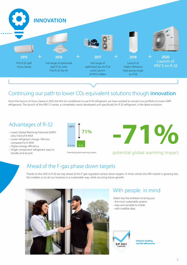
2013First R-32 splitUruru Sarara
2017
Full range of optimised Sky Air R-32
units Launch of HFO chillers
2016
Full range of optimised Split R-32 units
First R-32 Sky Air
2018
Launch of Daikin Altherma
heat pump range on R-32
2020Launch of
VRV 5 on R-32
71%100%
Potential global warming impact
R-410A R-32
Ahead of the F-gas phase down targets
Industry-leading real life efficienciesErP 2021
COMPLIANT
+ + + +
INNOVATION
Since the launch of Ururu Sarara in 2013, the first air conditioner to use R-32 refrigerant, we have worked to convert our portfolio to lower GWP refrigerants. The launch of the VRV 5 S-series, a completely newly developed unit specifically for R-32 refrigerant, is the latest evolution.
Continuing our path to lower CO2 equivalent solutions though innovation
4
CO
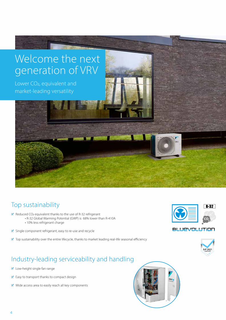
Welcome the next generation of VRVLower CO2, equivalent and market-leading versatility
ErP 2021COMPLIANT
Top sustainability Reduced CO2 equivalent thanks to the use of R-32 refrigerant
• R-32 Global Warming Potential (GWP) is 68% lower than R-410A • 10% less refrigerant charge
Single component refrigerant, easy to re-use and recycle
Top sustainability over the entire lifecycle, thanks to market leading real-life seasonal efficiency
Industry-leading serviceability and handling Low-height single fan range
Easy to transport thanks to compact design
Wide access area to easily reach all key components
5
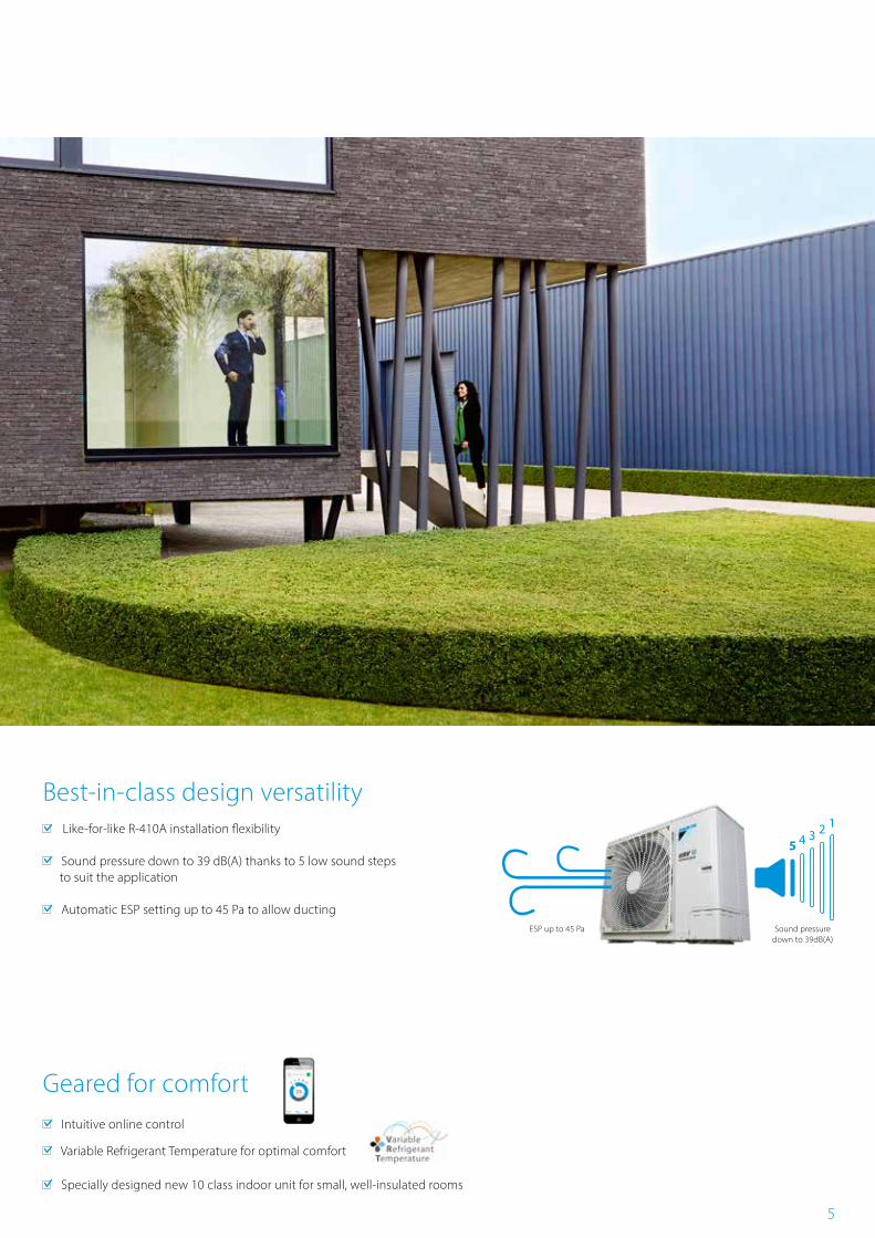
5 4 3 2 1
Best-in-class design versatility Like-for-like R-410A installation flexibility
Sound pressure down to 39 dB(A) thanks to 5 low sound steps to suit the application
Automatic ESP setting up to 45 Pa to allow ducting
Geared for comfort Intuitive online control
Variable Refrigerant Temperature for optimal comfort
Specially designed new 10 class indoor unit for small, well-insulated rooms
Sound pressure down to 39dB(A)
ESP up to 45 Pa
6
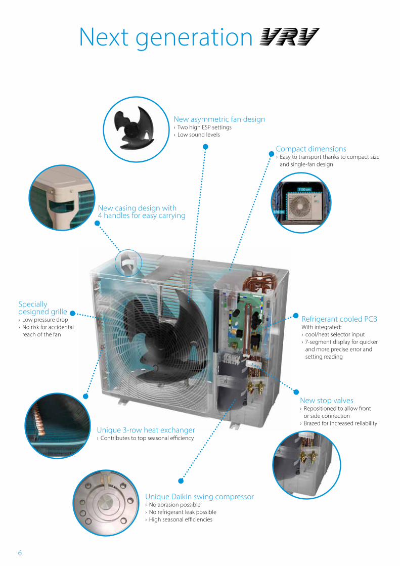
New casing design with 4 handles for easy carrying
New asymmetric fan design › Two high ESP settings › Low sound levels
Refrigerant cooled PCBWith integrated: › cool/heat selector input › 7-segment display for quicker and more precise error and setting reading
Unique Daikin swing compressor › No abrasion possible › No refrigerant leak possible › High seasonal efficiencies
New stop valves › Repositioned to allow front or side connection
› Brazed for increased reliabilityUnique 3-row heat exchanger › Contributes to top seasonal efficiency
Compact dimensions › Easy to transport thanks to compact size and single-fan design
Next generation
Specially designed grille › Low pressure drop › No risk for accidental reach of the fan
7
RXYSA-AV/AY1
Outdoor unit RXYSA4AV1 RXYSA5AV1 RXYSA6AV1 RXYSA4AY1 RXYSA5AY1 RXYSA6AY1Capacity range HP 4 5 6 4 5 6Cooling capacity Prated,c kW 12.1 14.0 15.5 12.1 14.0 15.5Heating capacity Prated,h kW 8.4 9.7 10.7 8.4 9.7 10.7
Max. 6°CWB kW 14.2 16.0 18.0 14.2 16.0 18.0Recommended combination 3xFXSA25 +
1xFXSA324xFXSA32 2xFXSA32 +
2xFXSA403xFXSA25 +
1xFXSA324xFXSA32 2xFXSA32 +
2xFXSA40ηs,c % 324.5 306.1 301.0 312.5 294.8 289.9ηs,h % 200.5 185.7 183.6 193.1 178.8 176.8SEER 8.2 7.7 7.6 7.9 7.4 7.3SCOP 5.1 4.7 4.7 4.9 4.5 4.5Maximum number of connectable indoor units 64 (1)Indoor index connection
Min. 50 62.5 70 50 62.5 70Nom. 100 125 140 100 125 140Max. 130 162.5 182 130 162.5 182
Dimensions Unit HeightxWidthxDepth mm 870x1,100x460Weight Unit kg 103 102Sound power level Cooling Nom. dBA 67 68.1 69 67 68.1 69
Heating Nom. dBA 68 69.2 70 68 69.2 70Sound pressure level Cooling Nom. dBA 49 51 51 49 51 51
Heating Nom. dBA 50 52 52 50 52 52Operation range Cooling Min.~Max. °CDB -5.0 ~ 46.0
Heating Min.~Max. °CWB -20.0 ~ 15.5Refrigerant Type/GWP R-32/675
Charge kg/TCO2Eq 3.4 / 2.3Piping connections Liquid OD mm 9.52
Gas OD mm 15.9Total piping length
system Actual m 300
Height Difference
OU-IU Outdoor unit in highest position
m 50
Indoor unit in highest position
m 40
Power supply Phase/Frequency/Voltage Hz/V 1~/50/220-240 3~/50/380-415Current - 50Hz Maximum fuse amps (MFA) A 32 16
*Note: blue cells contain preliminary data
(1) Actual number of units depends on the indoor unit type and the connection ratio restriction for the system (being 50% <= 130%)
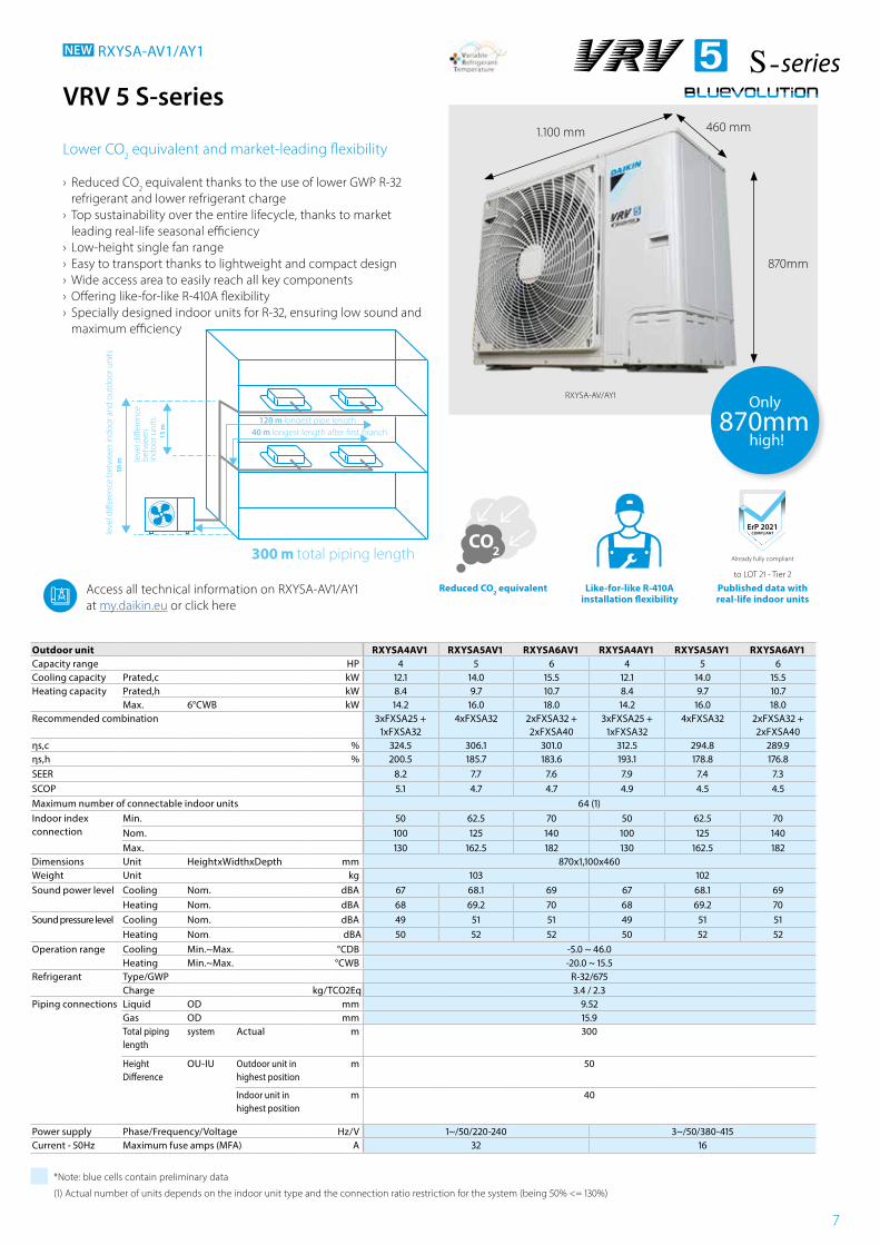
VRV 5 S-series
Lower CO2 equivalent and market-leading flexibility
› Reduced CO2 equivalent thanks to the use of lower GWP R-32 refrigerant and lower refrigerant charge
› Top sustainability over the entire lifecycle, thanks to market leading real-life seasonal efficiency
› Low-height single fan range › Easy to transport thanks to lightweight and compact design › Wide access area to easily reach all key components › Offering like-for-like R-410A flexibility › Specially designed indoor units for R-32, ensuring low sound and maximum efficiency
NEW RXYSA-AV1/AY1
870mm
Only870mm
high!
Access all technical information on RXYSA-AV1/AY1 at my.daikin.eu or click here
Already fully compliant
to LOT 21 - Tier 2
ErP 2021COMPLIANT
Published data with real-life indoor units
Reduced CO2 equivalent Like-for-like R-410A installation flexibility
CO
1.100 mm 460 mm
leve
l di�
eren
ce b
etw
een
indo
or a
nd o
utdo
or u
nits
leve
l di�
eren
ce
betw
een
indo
or u
nits
50 m
15 m 40 m longest length after �rst branch
120 m longest pipe length
300 m total piping length
8
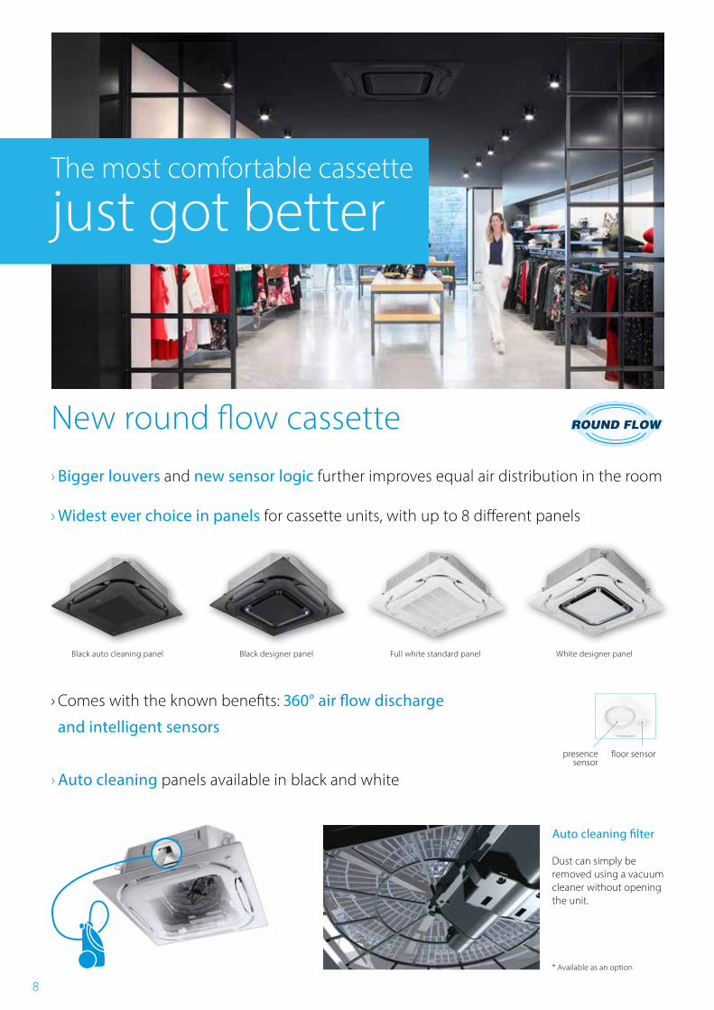
New round flow cassette
› Bigger louvers and new sensor logic further improves equal air distribution in the room
› Widest ever choice in panels for cassette units, with up to 8 different panels
› Comes with the known benefits: 360° air flow discharge
and intelligent sensors
› Auto cleaning panels available in black and white
The most comfortable cassette
just got better
Black designer panel Full white standard panel White designer panelBlack auto cleaning panel
presence sensor
floor sensor
Dust can simply be removed using a vacuum cleaner without opening the unit.
* Available as an option
Auto cleaning filter
9
Indoor unit FXFA 20A 25A 32A 40A 50A 63A 80A 100A 125ACooling capacity Total capacity Nom. kW 2.20 2.80 3.60 4.50 5.60 7.10 9.00 11.20 14.00Heating capacity Total capacity Nom. kW 2.5 3.2 4.0 5.0 6.3 8.0 10.0 12.5 16.0 Power input - 50Hz Cooling Nom. kW 0.04 0.05 0.06 0.09 0.12 0.19
Heating Nom. kW 0.04 0.05 0.06 0.09 0.11 0.18Dimensions Unit HeightxWidthxDepth mm 204x840x840 246x840x840 288x840x840Weight Unit kg 19 20 21 24 26Casing Material Galvanised steel plateDecoration panel Model Standard panels: BYCQ140E - white with grey louvers / BYCQ140EW - full white / BYCQ140EB - black
Auto cleaning panels BYCQ140EGF - white / BYCQ140EGFB - blackDesigner panels: BYCQ140EP - white / BYCQ140EPB - black
Dimensions HeightxWidthxDepth mm Standard panels: 50x950x950 / Auto cleaning panels: 130x950x950 / Designer panels: 50x950x950Weight kg Standard panels: 5.4 / Auto cleaning panels: 10.3 / Designer panels: 5.4
Fan Air flow rate - 50Hz
Cooling Low/High m³/min 8.8/12.5 9.5/13.6 10.5/15.0 10.5/16.5 12.4/22.8 12.4/26.5 19.9/33.0Heating Low/High m³/min 8.8/12.5 9.5/13.6 10.5/15.0 10.5/16.5 12.4/22.8 12.4/26.5 19.9/33.0
Air filter Type Resin netSound power level Cooling High dBA 49 51 53 55 60 61Sound pressure level
Cooling Low/Nom./High dBA 28.0/29.0/31.0 29.0/31.0/33.0 30.0/33.0/35.0 30.0/34.0/38.0 30.0/37.0/43.0 36.0/41.0/45.0Heating Low/Nom./High dBA 28.0/29.0/31.0 29.0/31.0/33.0 30.0/33.0/35.0 30.0/34.0/38.0 30.0/37.0/43.0 36.0/41.0/45.0
Refrigerant Type/GWP R-32 / 675Piping connections Liquid OD mm 6.35 9.52
Gas OD mm 9.52 12.7 15.9Drain VP25 (O.D. 32 / I.D. 25)
Power supply Phase/Frequency/Voltage Hz/V 1~/50/60/220-240/220Current - 50Hz Maximum fuse amps (MFA) (1) A 16Control systems Infrared remote control BRC7FA532F (2)
Wired remote control BRC1H52W/S/K
(1) MFA is used to select the circuit breaker and the ground fault circuit interrupter (earth leakage circuit breaker). For more detailed information on each combination, please refer to the electrical data drawing
*Note: blue cells contain preliminary data
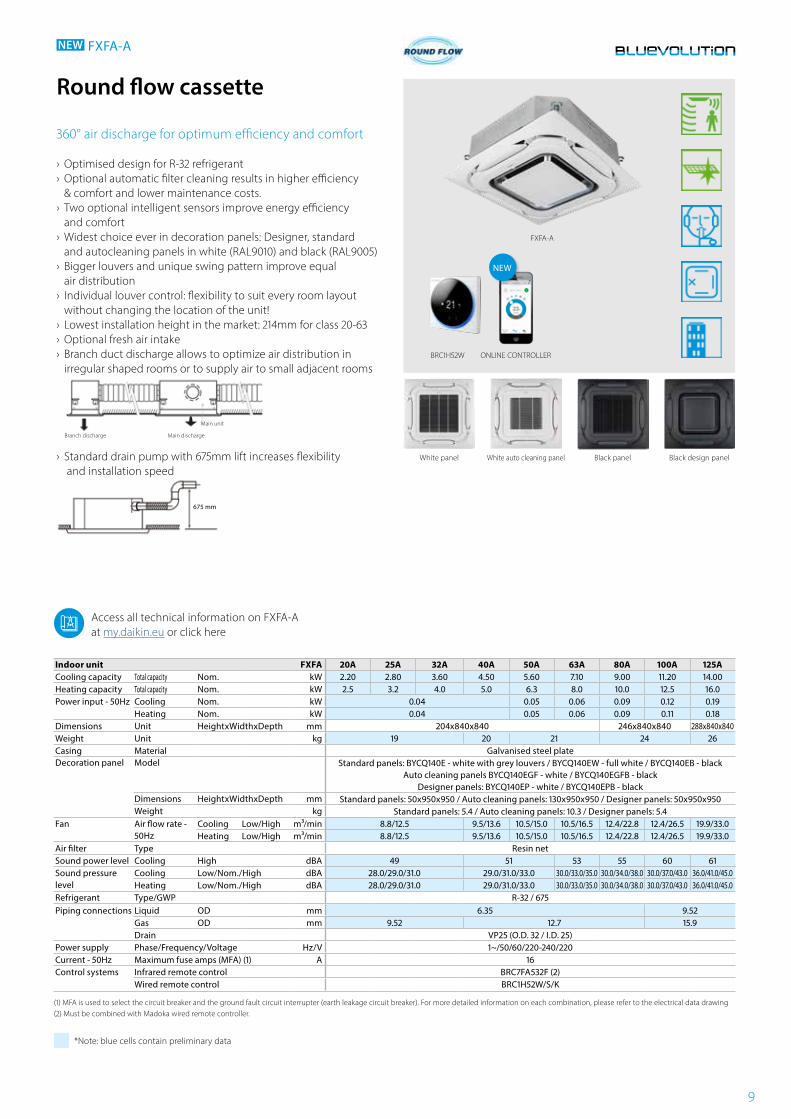
Round flow cassette
360° air discharge for optimum efficiency and comfort
› Optimised design for R-32 refrigerant › Optional automatic filter cleaning results in higher efficiency & comfort and lower maintenance costs.
› Two optional intelligent sensors improve energy efficiency and comfort
› Widest choice ever in decoration panels: Designer, standard and autocleaning panels in white (RAL9010) and black (RAL9005)
› Bigger louvers and unique swing pattern improve equal air distribution
› Individual louver control: flexibility to suit every room layout without changing the location of the unit!
› Lowest installation height in the market: 214mm for class 20-63 › Optional fresh air intake › Branch duct discharge allows to optimize air distribution in irregular shaped rooms or to supply air to small adjacent rooms
›
Branch discharge Main discharge
Main unit
Standard drain pump with 675mm lift increases flexibility and installation speed
675 mm
NEW FXFA-A
ONLINE CONTROLLERBRC1H52W
Black design panelWhite auto cleaning panel Black panel
FXFA-A
White panel
Access all technical information on FXFA-A at my.daikin.eu or click here
NEW
(2) Must be combined with Madoka wired remote controller.
10
11
BRC1H52W
FXZA-A
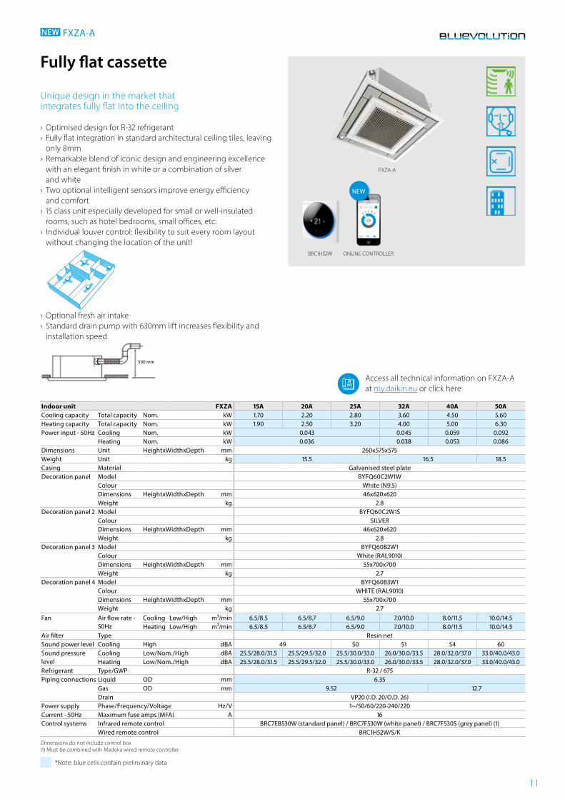
Indoor unit FXZA 15A 20A 25A 32A 40A 50ACooling capacity Total capacity Nom. kW 1.70 2.20 2.80 3.60 4.50 5.60Heating capacity Total capacity Nom. kW 1.90 2.50 3.20 4.00 5.00 6.30Power input - 50Hz Cooling Nom. kW 0.043 0.045 0.059 0.092
Heating Nom. kW 0.036 0.038 0.053 0.086Dimensions Unit HeightxWidthxDepth mm 260x575x575Weight Unit kg 15.5 16.5 18.5Casing Material Galvanised steel plateDecoration panel Model BYFQ60C2W1W
Colour White (N9.5)Dimensions HeightxWidthxDepth mm 46x620x620Weight kg 2.8
Decoration panel 2 Model BYFQ60C2W1SColour SILVERDimensions HeightxWidthxDepth mm 46x620x620Weight kg 2.8
Decoration panel 3 Model BYFQ60B2W1Colour White (RAL9010)Dimensions HeightxWidthxDepth mm 55x700x700Weight kg 2.7
Decoration panel 4 Model BYFQ60B3W1Colour WHITE (RAL9010)Dimensions HeightxWidthxDepth mm 55x700x700Weight kg 2.7
Fan Air flow rate - 50Hz
Cooling Low/High m³/min 6.5/8.5 6.5/8.7 6.5/9.0 7.0/10.0 8.0/11.5 10.0/14.5Heating Low/High m³/min 6.5/8.5 6.5/8.7 6.5/9.0 7.0/10.0 8.0/11.5 10.0/14.5
Air filter Type Resin netSound power level Cooling High dBA 49 50 51 54 60Sound pressure level
Cooling Low/Nom./High dBA 25.5/28.0/31.5 25.5/29.5/32.0 25.5/30.0/33.0 26.0/30.0/33.5 28.0/32.0/37.0 33.0/40.0/43.0Heating Low/Nom./High dBA 25.5/28.0/31.5 25.5/29.5/32.0 25.5/30.0/33.0 26.0/30.0/33.5 28.0/32.0/37.0 33.0/40.0/43.0
Refrigerant Type/GWP R-32 / 675Piping connections Liquid OD mm 6.35
Gas OD mm 9.52 12.7Drain VP20 (I.D. 20/O.D. 26)
Power supply Phase/Frequency/Voltage Hz/V 1~/50/60/220-240/220Current - 50Hz Maximum fuse amps (MFA) A 16Control systems Infrared remote control BRC7EB530W (standard panel) / BRC7F530W (white panel) / BRC7F530S (grey panel) (1)
Wired remote control BRC1H52W/S/K
Dimensions do not include control box (1) Must be combined with Madoka wired remote controller.
*Note: blue cells contain preliminary data
Fully flat cassette
Unique design in the market that integrates fully flat into the ceiling
› Optimised design for R-32 refrigerant › Fully flat integration in standard architectural ceiling tiles, leaving only 8mm
› Remarkable blend of iconic design and engineering excellence with an elegant finish in white or a combination of silver and white
› Two optional intelligent sensors improve energy efficiency and comfort
› 15 class unit especially developed for small or well-insulated rooms, such as hotel bedrooms, small offices, etc.
› Individual louver control: flexibility to suit every room layout without changing the location of the unit!
› Optional fresh air intake › Standard drain pump with 630mm lift increases flexibility and installation speed
500 mm
NEW FXZA-A
Access all technical information on FXZA-A at my.daikin.eu or click here
ONLINE CONTROLLER
NEW
12
www.youtube.com/DaikinEuropeCombination table
BAE20A62 BAE20A82 BAE20A102
Heigth (mm) 210
Width (mm) 830 1,030 1,230
Depth (mm) 188
SpecificationsSplit / Sky Air VRV
FDXM-F9 FXDA-A/FXDQ-A3
25 35 50 60 15 20 25 32 40 50 63
BAE20A62
BAE20A82
BAE20A102
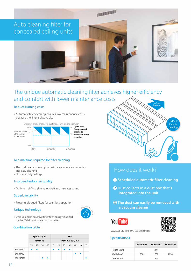
The unique automatic cleaning filter achieves higher efficiency and comfort with lower maintenance costs Reduce running costs
› Automatic filter cleaning ensures low maintenance costs because the filter is always clean
Minimal time required for filter cleaning
› The dust box can be emptied with a vacuum cleaner for fast and easy cleaning
› No more dirty ceilings
Improved indoor air quality
› Optimum airflow eliminates draft and insulates sound
Superb reliability
› Prevents clogged filters for seamless operation
Unique technology
› Unique and innovative filter technology inspired by the Daikin auto cleaning cassette
Auto cleaning filter for concealed ceiling units
UNIQUEPatents
pending
airflow direction
Efficiency profile change for duct indoor unit during operation
start 6 months 12 months
Gradual loss of efficiency due to dirty filter
100%
0%
Up to 20% Energy saved thanks to automatic filter cleaning
How does it work?
1 Scheduled automatic filter cleaning 2 Dust collects in a dust box that’s
integrated into the unit
3 The dust can easily be removed with a vacuum cleaner
13
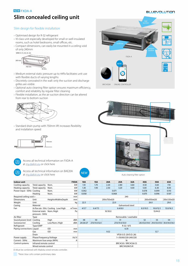
FXDA-A
Indoor unit FXDA 10A 15A 20A 25A 32A 40A 50A 63ACooling capacity Total capacity Nom. kW 1.10 1.70 2.20 2.80 3.60 4.50 5.60 7.10Heating capacity Total capacity Nom. kW 1.30 1.90 2.50 3.20 4.00 5.00 6.30 8.00Power input - 50Hz Cooling Nom. kW 0.062 0.071 0.078 0.099 0.110
Heating Nom. kW 0.058 0.068 0.075 0.096 0.107Required ceiling void > mm 240Dimensions Unit HeightxWidthxDepth mm 200x750x620 200x950x620 200x1,150x620Weight Unit kg 22.5 22.0 26.0 29.0Casing Material Galvanised steelFan Air flow rate - 50Hz Cooling Low/High m³/min 4/5.7 6.4/7.5 6.4/8.0 8.5/10.5 10.0/12.5 13.0/16.5
External static pressure - 50Hz
Nom./High Pa 10/30.0 15/44.0
Air filter Type Removable / washableSound power level Cooling High dBA 48 50 51 52 53 54Sound pressure level Cooling Low/Nom./High dBA 24/26/27 27.0/31.0/32.0 27.0/31.0/33.0 28.0/32.0/34.0 29.0/33.0/35.0 30.0/34.0/36.0Refrigerant Type/GWP R-32 / 675Piping connections Liquid OD mm 6.35
Gas OD mm 9.52 12.7Drain VP20 (I.D. 20/O.D. 26)
Power supply Phase/Frequency/Voltage Hz/V 1~/50/60/220-240/220Current - 50Hz Maximum fuse amps (MFA) A 16Control systems Infrared remote control BRC4C65 / BRC4C66 (1)
Wired remote control BRC1H52W/S/K
(1) Must be combined with Madoka wired remote controller.
*Note: blue cells contain preliminary data
Slim concealed ceiling unit
Slim design for flexible installation
› Optimised design for R-32 refrigerant › 10 class unit especially developed for small or well-insulated rooms, such as hotel bedrooms, small offices, etc.
› Compact dimensions, can easily be mounted in a ceiling void of only 240mm
›
200 mm
700 mm50 mm
SERIE A (15, 20, 25, 32)
Medium external static pressure up to 44Pa facilitates unit use with flexible ducts of varying lengths
› Discretely concealed in the wall: only the suction and discharge grilles are visible
› Optional auto cleaning filter option ensures maximum efficiency, comfort and reliability by regular filter cleaning
› Flexible installation, as the air suction direction can be altered from rear to bottom suction
› Standard drain pump with 750mm lift increases flexibility and installation speed
750 mm
NEW FXDA-A
outblow
rear suction
bottom suction
Auto cleaning filter option
Access all technical information on FXDA-A at my.daikin.eu or click here
Access all technical information on BAE20A at my.daikin.eu or click here
BRC1H52W ONLINE CONTROLLER
NEW
NEW
14
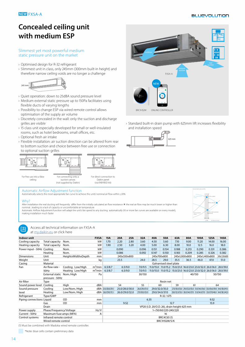
FXSA-A
Indoor unit FXSA 15A 20A 25A 32A 40A 50A 63A 80A 100A 125A 140ACooling capacity Total capacity Nom. kW 1.70 2.20 2.80 3.60 4.50 5.60 7.10 9.00 11.20 14.00 16.00Heating capacity Total capacity Nom. kW 1.90 2.50 3.20 4.00 5.00 6.30 8.00 10.0 12.5 16.0 18.0Power input - 50Hz Cooling Nom. kW 0.090 0.096 0.151 0.154 0.188 0.213 0.290 0.331 0.386
Heating Nom. kW 0.086 0.092 0.147 0.150 0.183 0.209 0.285 0.326 0.382Dimensions Unit HeightxWidthxDepth mm 245x550x800 245x700x800 245x1,000x800 245x1,400x800 245x1,550x800Weight Unit kg 23.5 24.0 28.5 29.0 35.5 36.5 46.0 47.0 51.0Casing Material Galvanised steel plateFan Air flow rate -
50HzCooling Low/High m³/min 6.5/8.7 6.5/9.0 7.0/9.5 11.0/15.0 11.0/15.2 15.0/21.0 16.0/23.0 23.0/32.0 26.0/36.0 28.0/39.0Heating Low/High m³/min 6.5/8.7 6.5/9.0 7.0/9.5 11.0/15.0 11.0/15.2 15.0/21.0 16.0/23.0 23.0/32.0 26.0/36.0 28.0/39.0
External static pressure - 50Hz
Nom./High Pa 30/150 40/150 50/150
Air filter Type Resin netSound power level Cooling High dBA 54 55 60 59 61 64Sound pressure level
Cooling Low/Nom./High dBA 25.0/28.0/29.5 25.0/28.0/30.0 26.0/29.0/31.0 29.0/32.0/35.0 27.0/30.0/33.0 29.0/32.0/35.0 31.0/34.0/36.0 33.0/36.0/39.0 34.0/38.0/41.5Heating Low/Nom./High dBA 26.0/29.0/31.5 26.0/29.0/32.0 27.0/30.0/33.0 29.0/34.0/37.0 28.0/32.0/35.0 30.0/34.0/37.0 31.0/34.0/37.0 33.0/37.0/40.0 34.0/38.5/42.0
Refrigerant Type/GWP R-32 / 675Piping connections Liquid OD mm 6.35 9.52
Gas OD mm 9.52 12.7 15.9Drain VP20 (I.D. 20/O.D. 26), drain height 625 mm
Power supply Phase/Frequency/Voltage Hz/V 1~/50/60/220-240/220Current - 50Hz Maximum fuse amps (MFA) A 16Control systems Infrared remote control BRC4C65 (1)
Wired remote control BRC1H52W/S/K
(1) Must be combined with Madoka wired remote controller.
*Note: blue cells contain preliminary data
Concealed ceiling unit with medium ESP
Slimmest yet most powerful medium static pressure unit on the market
› Optimised design for R-32 refrigerant › Slimmest unit in class, only 245mm (300mm built-in height) and therefore narrow ceiling voids are no longer a challenge
›
245 mm
Quiet operation: down to 25dBA sound pressure level › Medium external static pressure up to 150Pa facilitates using flexible ducts of varying lengths
› Possibility to change ESP via wired remote control allows optimisation of the supply air volume
› Discretely concealed in the wall: only the suction and discharge grilles are visible
› 15 class unit especially developed for small or well-insulated rooms, such as hotel bedrooms, small offices, etc.
› Optional fresh air intake › Flexible installation: air suction direction can be altered from rear to bottom suction and choice between free use or connection to optional suction grilles
////////////////////////////////////////// ////////////////////////////////////////////////////////////////////////////////////
For free use into a false ceiling
For connecting onto a suction canvas
(not supplied by Daikin)
For direct connection to Daikin panel
(via EKBYBSD kit)
NEW FXSA-A
outblow
bottom suction
rear suction
› Standard built-in drain pump with 625mm lift increases flexibility and installation speed
625 mm
Automatic Airflow Adjustment functionAutomatically selects the most appropriate fan curve to achieve the units’ nominal air flow within ±10%
Why?After installation the real ducting will frequently differ from the initially calculated air flow resistance the real air flow may be much lower or higher than nominal , leading to a lack of capacity or uncomfortable air temperatureAutomatic Airflow Adjustment function will adapt the unit’s fan speed to any ducting automatically (10 or more fan curves are available on every model), making installation much faster
Access all technical information on FXSA-A at my.daikin.eu or click here
±
External static pressure (Pa)
Fan characteristic curves
Duct resistance curves
Air flow (rated)
Air flow (m3/min)
Air flow (with automatic adjustment)
Air flow (actual)
BRC1H52W ONLINE CONTROLLER
NEW
15
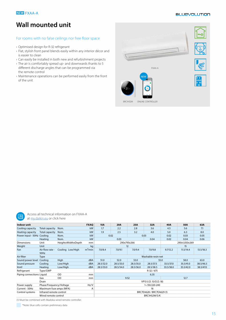
FXAA-A
Indoor unit FXAQ 15A 20A 25A 32A 40A 50A 63ACooling capacity Total capacity Nom. kW 1.7 2.2 2.8 3.6 4.5 5.6 7.1Heating capacity Total capacity Nom. kW 1.9 2.5 3.2 4.0 5.0 6.3 8.0Power input - 50Hz Cooling Nom. kW 0.02 0.03 0.02 0.03 0.05
Heating Nom. kW 0.03 0.04 0.02 0.04 0.06Dimensions Unit HeightxWidthxDepth mm 290x795x266 290x1,050x269Weight Unit kg 12 15Fan Air flow rate -
50HzCooling Low/High m³/min 7.0/8.4 7.0/9.1 7.0/9.4 7.0/9.8 9.7/12.2 11.5/14.4 13.5/18.3
Air filter Type Washable resin netSound power level Cooling High dBA 51.0 52.0 53.0 55.0 58.0 63.0Sound pressure level
Cooling Low/High dBA 28.5/32.0 28.5/33.0 28.5/35.0 28.5/37.5 33.5/37.0 35.5/41.0 38.5/46.5Heating Low/High dBA 28.5/33.0 28.5/34.0 28.5/36.0 28.5/38.5 33.5/38.0 35.5/42.0 38.5/47.0
Refrigerant Type/GWP R-32 / 675Piping connections Liquid OD mm 6.35
Gas OD mm 9.52 12.7Drain VP13 (I.D. 15/O.D. 18)
Power supply Phase/Frequency/Voltage Hz/V 1~/50/220-240Current - 50Hz Maximum fuse amps (MFA) A 16Control systems Infrared remote control BRC7EA628 / BRC7EA629 (1)
Wired remote control BRC1H52W/S/K
(1) Must be combined with Madoka wired remote controller.
*Note: blue cells contain preliminary data
Wall mounted unit
For rooms with no false ceilings nor free floor space
› Optimised design for R-32 refrigerant › Flat, stylish front panel blends easily within any interior décor and is easier to clean
› Can easily be installed in both new and refurbishment projects › The air is comfortably spread up- and downwards thanks to 5 different discharge angles that can be programmed via the remote control
› Maintenance operations can be performed easily from the front of the unit
NEW FXAA-A
Access all technical information on FXAA-A at my.daikin.eu or click here
BRC1H52W ONLINE CONTROLLER
NEW
16
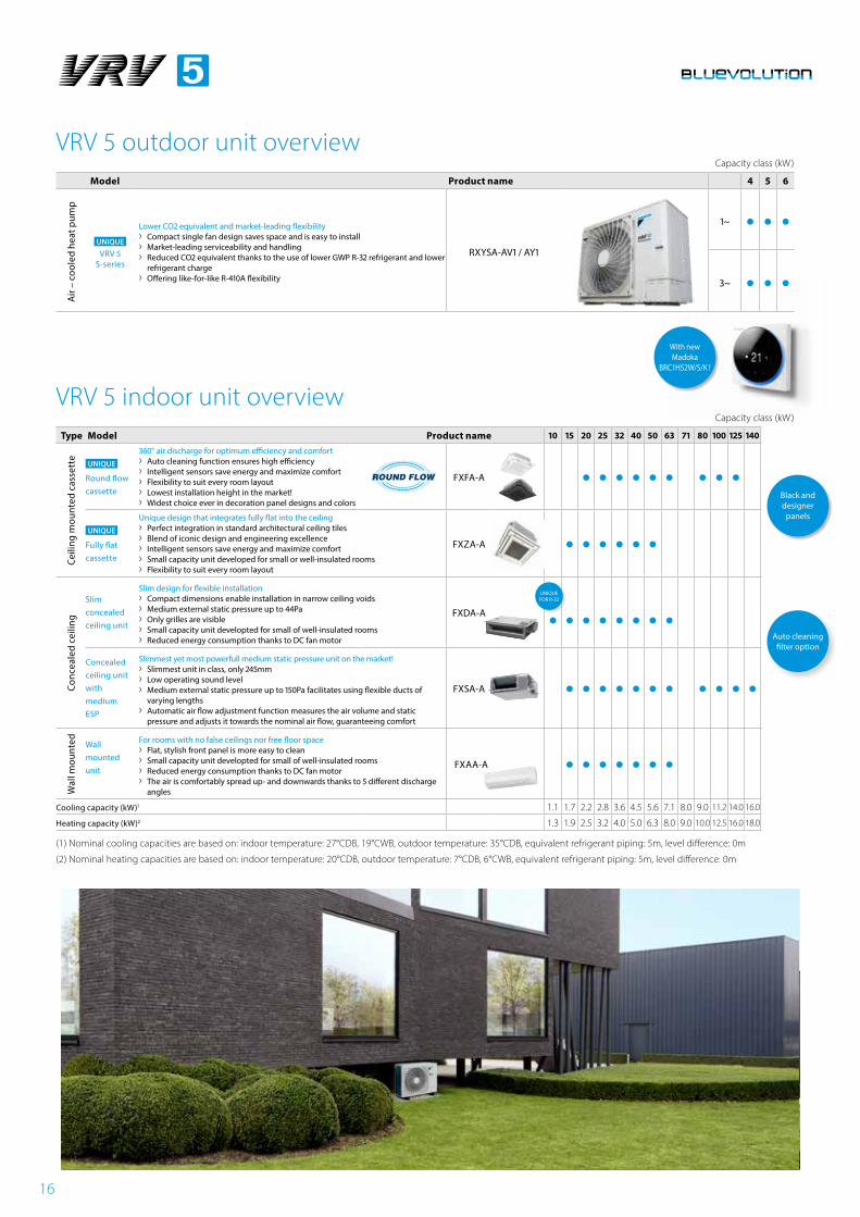
VRV 5 outdoor unit overviewCapacity class (kW)
Model Product name 4 5 6
Air
– co
oled
hea
t pum
p
UNIQUE
VRV 5 S-series
Lower CO2 equivalent and market-leading flexibility › Compact single fan design saves space and is easy to install › Market-leading serviceability and handling › Reduced CO2 equivalent thanks to the use of lower GWP R-32 refrigerant and lower
refrigerant charge › Offering like-for-like R-410A flexibility
RXYSA-AV1 / AY1
1~
3~
VRV 5 indoor unit overviewCapacity class (kW)
Type Model Product name 10 15 20 25 32 40 50 63 71 80 100 125 140
Ceili
ng m
ount
ed c
asse
tte
UNIQUE
Round flow cassette
360° air discharge for optimum efficiency and comfort › Auto cleaning function ensures high efficiency › Intelligent sensors save energy and maximize comfort › Flexibility to suit every room layout › Lowest installation height in the market! › Widest choice ever in decoration panel designs and colors
FXFA-A
UNIQUE
Fully flat cassette
Unique design that integrates fully flat into the ceiling › Perfect integration in standard architectural ceiling tiles › Blend of iconic design and engineering excellence › Intelligent sensors save energy and maximize comfort › Small capacity unit developed for small or well-insulated rooms › Flexibility to suit every room layout
FXZA-A
Conc
eale
d ce
iling
Slim concealed ceiling unit
Slim design for flexible installation › Compact dimensions enable installation in narrow ceiling voids › Medium external static pressure up to 44Pa › Only grilles are visible › Small capacity unit developted for small of well-insulated rooms › Reduced energy consumption thanks to DC fan motor
FXDA-A
Concealed ceiling unit with medium ESP
Slimmest yet most powerfull medium static pressure unit on the market! › Slimmest unit in class, only 245mm › Low operating sound level › Medium external static pressure up to 150Pa facilitates using flexible ducts of
varying lengths › Automatic air flow adjustment function measures the air volume and static
pressure and adjusts it towards the nominal air flow, guaranteeing comfort
FXSA-A
Wal
l mou
nted
Wall mounted unit
For rooms with no false ceilings nor free floor space › Flat, stylish front panel is more easy to clean › Small capacity unit developted for small of well-insulated rooms › Reduced energy consumption thanks to DC fan motor › The air is comfortably spread up- and downwards thanks to 5 different discharge
angles
FXAA-A
Cooling capacity (kW)1 1.1 1.7 2.2 2.8 3.6 4.5 5.6 7.1 8.0 9.0 11.2 14.0 16.0
Heating capacity (kW)2 1.3 1.9 2.5 3.2 4.0 5.0 6.3 8.0 9.0 10.0 12.5 16.0 18.0
(1) Nominal cooling capacities are based on: indoor temperature: 27°CDB, 19°CWB, outdoor temperature: 35°CDB, equivalent refrigerant piping: 5m, level difference: 0m
(2) Nominal heating capacities are based on: indoor temperature: 20°CDB, outdoor temperature: 7°CDB, 6°CWB, equivalent refrigerant piping: 5m, level difference: 0m
Auto cleaning filter option
UNIQUE FOR R-32
Black and designer
panels
With new Madoka
BRC1H52W/S/K !
17
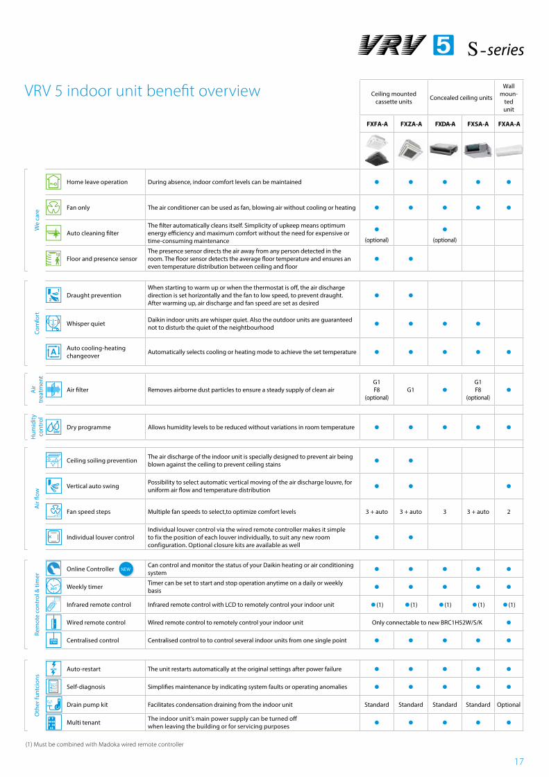
Ceiling mounted cassette units Concealed ceiling units
Wall moun-
ted unit
FXFA-A FXZA-A FXDA-A FXSA-A FXAA-A
We
care
Home leave operation During absence, indoor comfort levels can be maintained
Fan only The air conditioner can be used as fan, blowing air without cooling or heating
Auto cleaning filterThe filter automatically cleans itself. Simplicity of upkeep means optimum energy efficiency and maximum comfort without the need for expensive or time-consuming maintenance
(optional)
(optional)
Floor and presence sensorThe presence sensor directs the air away from any person detected in the room. The floor sensor detects the average floor temperature and ensures an even temperature distribution between ceiling and floor
Com
fort
Draught preventionWhen starting to warm up or when the thermostat is off, the air discharge direction is set horizontally and the fan to low speed, to prevent draught. After warming up, air discharge and fan speed are set as desired
Whisper quiet Daikin indoor units are whisper quiet. Also the outdoor units are guaranteed not to disturb the quiet of the neightbourhood
Auto cooling-heating changeover Automatically selects cooling or heating mode to achieve the set temperature
Air
trea
tmen
t
Air filter Removes airborne dust particles to ensure a steady supply of clean airG1F8
(optional)G1
G1F8
(optional)
Hum
idity
co
ntro
l
Dry programme Allows humidity levels to be reduced without variations in room temperature
Air
flow
Ceiling soiling prevention The air discharge of the indoor unit is specially designed to prevent air being blown against the ceiling to prevent ceiling stains
Vertical auto swing Possibility to select automatic vertical moving of the air discharge louvre, for uniform air flow and temperature distribution
Fan speed steps Multiple fan speeds to select,to optimize comfort levels 3 + auto 3 + auto 3 3 + auto 2
Individual louver controlIndividual louver control via the wired remote controller makes it simple to fix the position of each louver individually, to suit any new room configuration. Optional closure kits are available as well
Rem
ote
cont
rol &
tim
er
Online Controller Can control and monitor the status of your Daikin heating or air conditioning system
Weekly timer Timer can be set to start and stop operation anytime on a daily or weekly basis
Infrared remote control Infrared remote control with LCD to remotely control your indoor unit (1) (1) (1) (1) (1)
Wired remote control Wired remote control to remotely control your indoor unit Only connectable to new BRC1H52W/S/K Centralised control Centralised control to to control several indoor units from one single point
Oth
er fu
ntci
ons
Auto-restart The unit restarts automatically at the original settings after power failure Self-diagnosis Simplifies maintenance by indicating system faults or operating anomalies Drain pump kit Facilitates condensation draining from the indoor unit Standard Standard Standard Standard Optional
Multi tenant The indoor unit’s main power supply can be turned off when leaving the building or for servicing purposes
VRV 5 indoor unit benefit overview
(1) Must be combined with Madoka wired remote controller
NEW
18
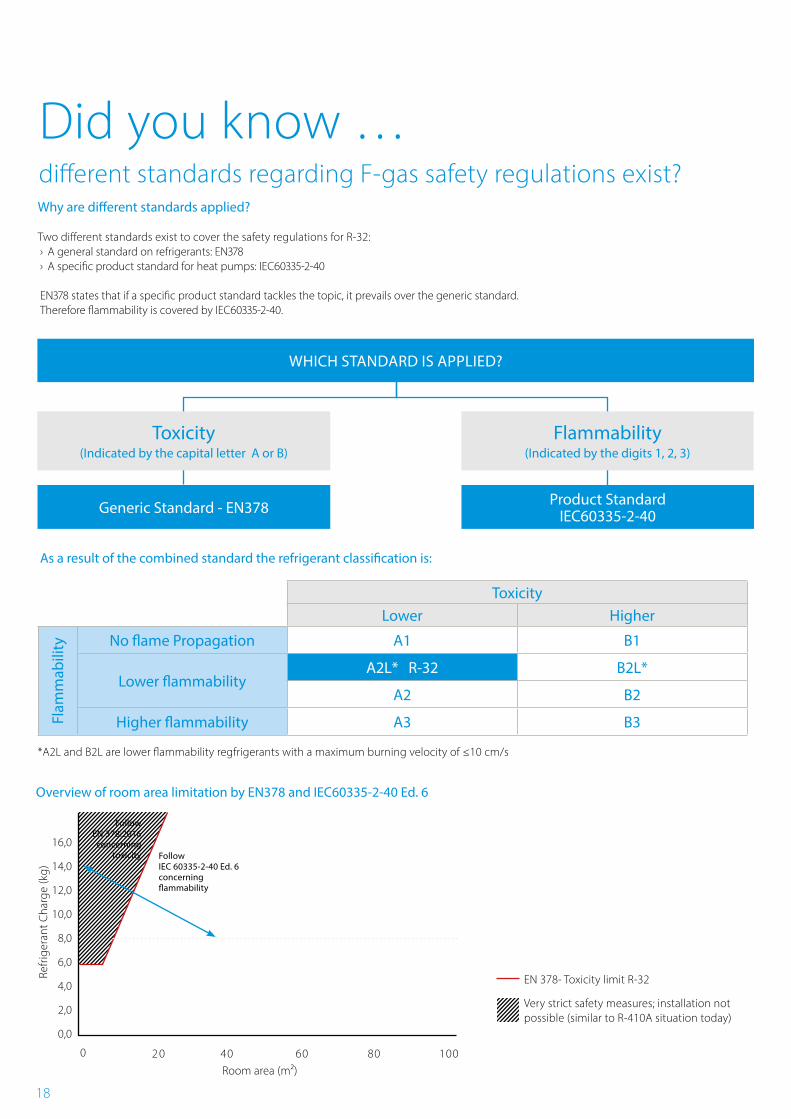
Did you know …different standards regarding F-gas safety regulations exist?
› A general standard on refrigerants: EN378 › A specific product standard for heat pumps: IEC60335-2-40
EN378 states that if a specific product standard tackles the topic, it prevails over the generic standard.Therefore flammability is covered by IEC60335-2-40.
ToxicityLower Higher
No flame Propagation A1 B1
Lower flammabilityA2L* R-32 B2L*
A2 B2
Higher flammability A3 B3
As a result of the combined standard the refrigerant classification is:
Overview of room area limitation by EN378 and IEC60335-2-40 Ed. 6
Refri
gera
nt C
harg
e (k
g)
16,0
14,0
12,0
10,0
8,0
6,0
4,0
2,0
0,0
2 0 40 60 80 100Room area (m2)
Follow EN 378:2016
concerning toxicity Follow
IEC 60335-2-40 Ed. 6concerning flammability
EN 378- Toxicity limit R-32
Very strict safety measures; installation not possible (similar to R-410A situation today)
0
Toxicity(Indicated by the capital letter A or B)
Flammability(Indicated by the digits 1, 2, 3)
Product StandardIEC60335-2-40Generic Standard - EN378
*A2L and B2L are lower flammability regfrigerants with a maximum burning velocity of ≤10 cm/s
Flam
mab
ility
WHICH STANDARD IS APPLIED?
Two different standards exist to cover the safety regulations for R-32:
Why are different standards applied?
19
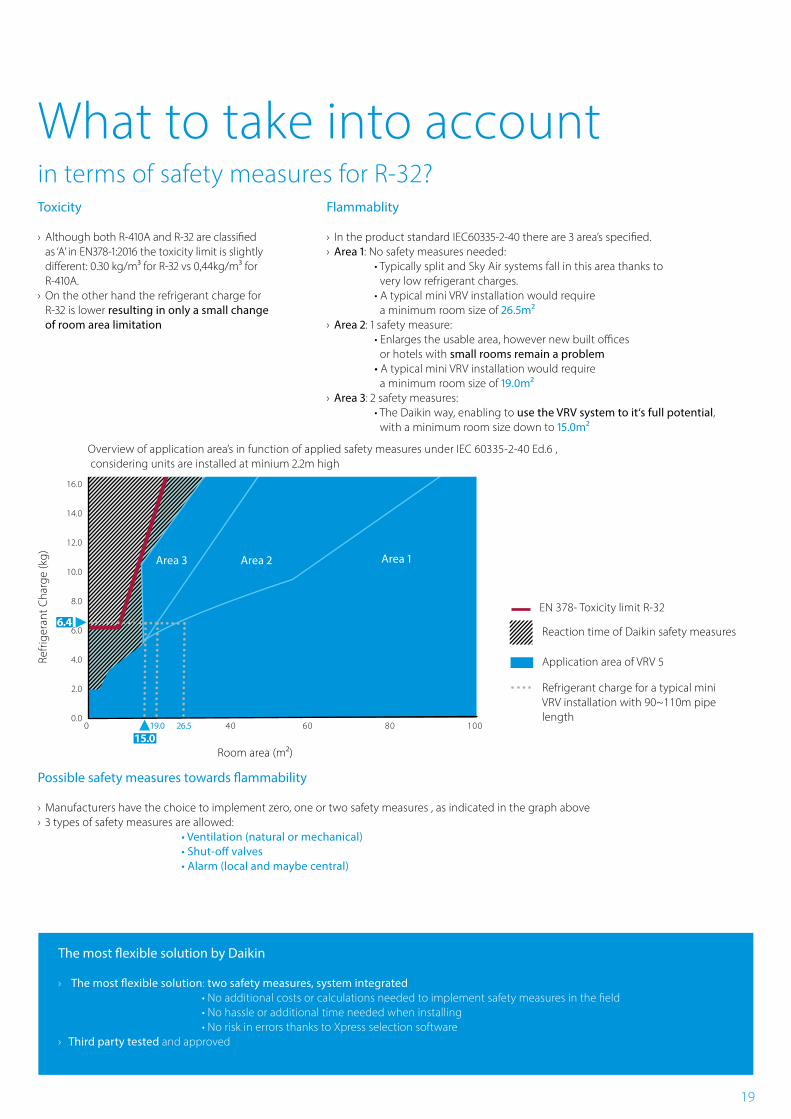
What to take into accountin terms of safety measures for R-32?Toxicity
› Although both R-410A and R-32 are classified as ‘A’ in EN378-1:2016 the toxicity limit is slightly different: 0.30 kg/m³ for R-32 vs 0,44kg/m³ for R-410A.
› On the other hand the refrigerant charge for R-32 is lower resulting in only a small change of room area limitation
Possible safety measures towards flammability
› Manufacturers have the choice to implement zero, one or two safety measures , as indicated in the graph above › 3 types of safety measures are allowed: • Ventilation (natural or mechanical) • Shut-off valves • Alarm (local and maybe central)
The most flexible solution by Daikin
› The most flexible solution: two safety measures, system integrated • No additional costs or calculations needed to implement safety measures in the field • No hassle or additional time needed when installing • No risk in errors thanks to Xpress selection software
› Third party tested and approved
Refri
gera
nt C
harg
e (k
g)
Room area (m2)
EN 378- Toxicity limit R-32
Reaction time of Daikin safety measures
Application area of VRV 5
16.0
14.0
12.0
10.0
8.0
6.0
4.0
2.0
0.00 40 60 80 10026.519.0
15.0
Area 1Area 3 Area 2
Flammablity
› In the product standard IEC60335-2-40 there are 3 area’s specified. › Area 1: No safety measures needed: • Typically split and Sky Air systems fall in this area thanks to very low refrigerant charges. • A typical mini VRV installation would require a minimum room size of 26.5m²
› Area 2: 1 safety measure: • Enlarges the usable area, however new built offices or hotels with small rooms remain a problem • A typical mini VRV installation would require a minimum room size of 19.0m²
› Area 3: 2 safety measures: • The Daikin way, enabling to use the VRV system to it‘s full potential, with a minimum room size down to 15.0m²
Refrigerant charge for a typical mini VRV installation with 90~110m pipe length
Overview of application area’s in function of applied safety measures under IEC 60335-2-40 Ed.6 , considering units are installed at minium 2.2m high
Area 3
6.4
20
Technical drawings
Outdoor unitsRXYSA-AV1/AY1 21
FXFA-A 24
FXZA-A 26
FXDA-A 27
FXSA-A 29
FXAA-A 32
21
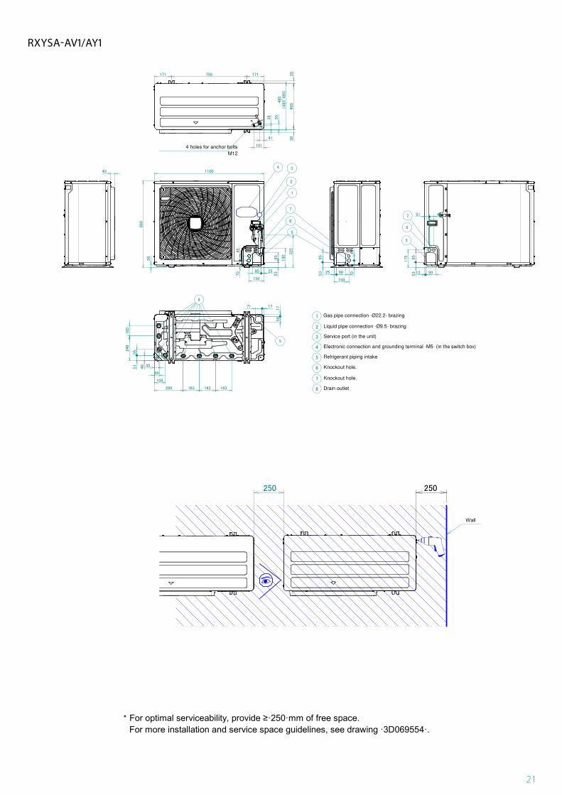
**
250 250
For more installation and service space guidelines, see drawing ·3D069554·.For optimal serviceability, provide ≥·250·mm of free space.
Wall
RZA-D
3D120935
171 758
485
(480~490)
30171
460
30
40
26
1100
259053
95
45
50
109
289 163 163 163
1771
17
58
46
51
59246
103
53
95
25 90
150
70
45
12 9953
95
175
51 45
1
2
3
4
5
6
7
8
Service port (in the unit)
Electronic connection and grounding terminal ·M5· (in the switch box)
Refrigerant piping intake
Drain outlet
34
5
5
6
7
Knockout hole.
Knockout hole.
4 holes for anchor bolts
M12
5
8
70
45
150
6
7
869
190
325
1
2
41
101
36 55
Gas pipe connection ·Ø22.2· brazing
Liquid pipe connection ·Ø9.5· brazing
RZA-D
3D120937
RXYSA-AV1/AY1
22
100 or more
100 or more
100 or more
100 or more
100 or more
100 or more
100 or more
100 or more
100 or more
100 or more
100 or more
100 or more
100 or more
100 or more
1000 or more
1000 or more300 or more
300 or more
200 or more
1000 or more
1000 or more
200 or more
150 or more
150 or more 150 or more
300 or more
500 or more
500 or more
500 or less
500 or less
500 or less
500 or less
500 or less
1000
or m
ore
1000
or m
ore
1000
or m
ore
1000 or more
1000
or m
ore
1000
or m
ore
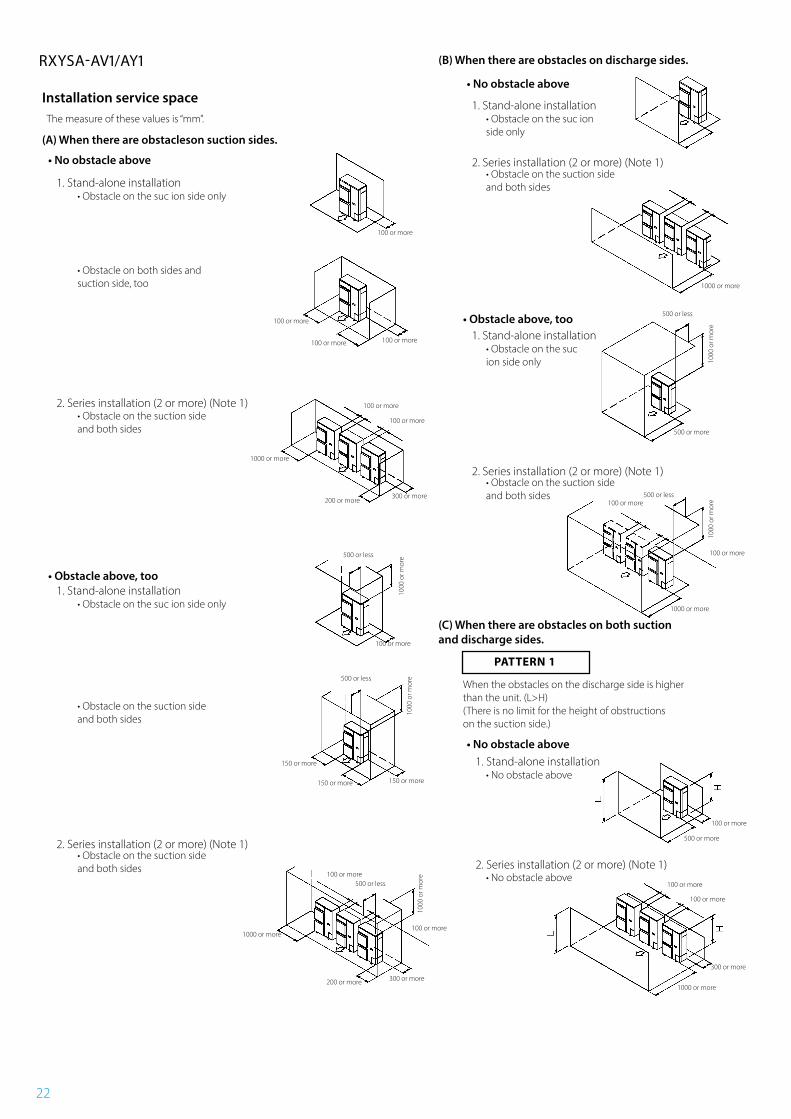
• Obstacle above, too
• Obstacle above, too
Installation service spaceThe measure of these values is “mm”.
(A) When there are obstacleson suction sides.
• No obstacle above
• No obstacle above
1. Stand-alone installation• Obstacle on the suc ion side only
1. Stand-alone installation• Obstacle on the suc ion side only
• Obstacle on both sides and suction side, too
2. Series installation (2 or more) (Note 1)
2. Series installation (2 or more) (Note 1)
2. Series installation (2 or more) (Note 1)
• Obstacle on the suction side and both sides
• Obstacle on the suction side and both sides
• Obstacle on the suction side and both sides
1. Stand-alone installation• Obstacle on the suc ion side only
1. Stand-alone installation• Obstacle on the suc ion side only
(B) When there are obstacles on discharge sides.
(C) When there are obstacles on both suction and discharge sides.
• Obstacle on the suction side and both sides
When the obstacles on the discharge side is higher than the unit. (L>H)(There is no limit for the height of obstructions on the suction side.)
2. Series installation (2 or more) (Note 1)• Obstacle on the suction side and both sides
• No obstacle above1. Stand-alone installation
• No obstacle above
2. Series installation (2 or more) (Note 1)• No obstacle above
RXYSA-AV1/AY1
PATTERN 1
23
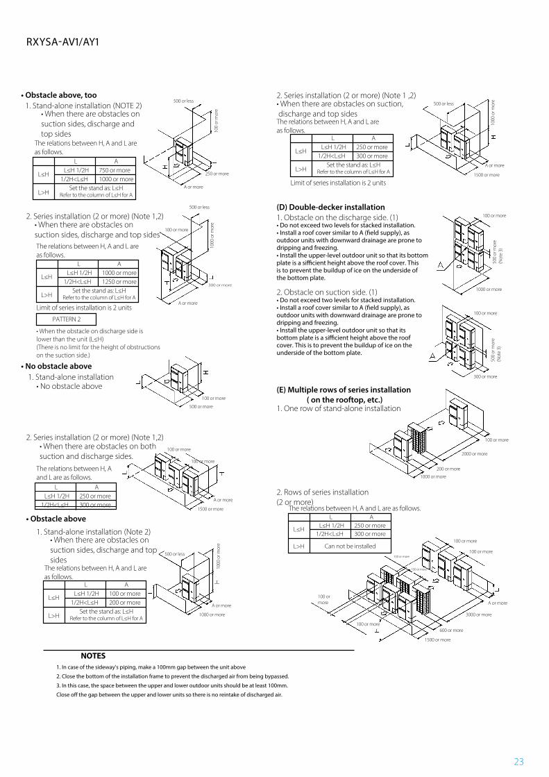
• Obstacle above, too1. Stand-alone installation (NOTE 2)
2. Series installation (2 or more) (Note 1 ,2)
2. Series installation (2 or more) (Note 1,2)
• When there are obstacles on suction sides, discharge and top sides
The relations between H, A and L are as follows.
The relations between H, A and L are as follows.
• When there are obstacles on suction sides, discharge and top sidesThe relations between H, A and L are as follows.
• When the obstacle on discharge side is lower than the unit (L≤H)(There is no limit for the height of obstructions on the suction side.)
• No obstacle above
• No obstacle above1. Stand-alone installation
2. Series installation (2 or more) (Note 1,2)• When there are obstacles on both suction and discharge sides.
The relations between H, A and L are as follows.
• Obstacle above
1. Stand-alone installation (Note 2)• When there are obstacles on suction sides, discharge and top sides
The relations between H, A and L are as follows.
Limit of series installation is 2 units
Limit of series installation is 2 units
L A
L≤H
L>H
L≤H 1/2H1/2H<L≤H
1000 or more1250 or more
Set the stand as: L≤HRefer to the column of L≤H for A
L AL≤H 1/2H
1/2H<L≤H250 or more300 or more
PATTERN 2
L A
L≤H
L>H
L≤H 1/2H1/2H<L≤H
100 or more200 or more
Set the stand as: L≤HRefer to the column of L≤H for A
500 or less
500 or less
500 or less
500 or less
100
or m
ore
500
or m
ore
(Not
e 3)
1000
or m
ore
500
or m
ore
(Not
e 3)
1000
or m
ore
1000
or m
ore
1000 or more
250 or more 1500 or more
100 or more
1000 or more
1500 or more
300 or more
100 or more
100 or more
100 or more
200 or more
600 or more
2000 or more
1000 or more
1500 or more
3000 or more
300 or more
100 or more
100 or more
100 or more
100 or more
100 or more
100 or more
100 or more
A or more
A or more
A or more
A or more
A or more
A or more
500 or more
100 or more
100 or more
L A
L≤H
L>H
L≤H 1/2H1/2H<L≤H
750 or more1000 or more
Set the stand as: L≤HRefer to the column of L≤H for A
• When there are obstacles on suction, discharge and top sides
L A
L≤H
L>H
L≤H 1/2H1/2H<L≤H
250 or more300 or more
Set the stand as: L≤HRefer to the column of L≤H for A
(D) Double-decker installation1. Obstacle on the discharge side. (1)
2. Obstacle on suction side. (1)
2. Rows of series installation(2 or more)
• Do not exceed two levels for stacked installation.• Install a roof cover similar to A (�eld supply), as outdoor units with downward drainage are prone todripping and freezing.• Install the upper-level outdoor unit so that its bottomplate is a si�cient height above the roof cover. Thisis to prevent the buildup of ice on the underside of the bottom plate.
• Do not exceed two levels for stacked installation.• Install a roof cover similar to A (�eld supply), as outdoor units with downward drainage are prone todripping and freezing.• Install the upper-level outdoor unit so that its bottom plate is a si�cient height above the roof cover. This is to prevent the buildup of ice on the underside of the bottom plate.
(E) Multiple rows of series installation ( on the rooftop, etc.)1. One row of stand-alone installation
The relations between H, A and L are as follows.L A
L≤H
L>H
L≤H 1/2H1/2H<L≤H
250 or more300 or more
Can not be installed
NOTES1. In case of the sideway’s piping, make a 100mm gap between the unit above
2. Close the bottom of the installation frame to prevent the discharged air from being bypassed.
3. In this case, the space between the upper and lower outdoor units should be at least 100mm.
Close o� the gap between the upper and lower units so there is no reintake of discharged air.
RXYSA-AV1/AY1
24
35
210
C
5
ARROW VIEW C
340
0-67
5
4 - M8 M10
1 243
950
950
87 6
AB
213
Ø75
10
DETAIL A
780
710420
9
420
DETAIL B
121.5350
9554.5
54.5
81 100 100 85
96.5
DETAIL B
350121.5
DETAIL A
FCAG100/125/140BVEBFCAHG71/100/125/140HVEBFXFQ80/100/125BVEB
81 100 100 85
8010
010
080
54.554.5 96.5
25.4
121.
535
0
95
6753
121.
5 25.4
350
8010
010
080
96.5
96.5
53
FCAG35/50/60/71BVEBFXFQ20/25/32/40/50/63BVEB
FCAG100/125/140BVEBFCAHG71/100/125/140HVEBFXFQ80/100/125BVEB
A
B
860-910
860-
910
35
10° 10°
256(*3)(*2) (*1)
·1500· or more·2000· or more
·4000· or more
Ceiling-mounted lightingOther unitAir fan
(*1)Not applicable to recessed lighting.(*2)Required space for entering with vacuum cleaner tube.(*3)Make sure the decoration panel discharge outlet is not blocked.
·1500· or more·200· or more
·200· or more
·1500· or more
·1500· or more
·1500· or more
Required installation spaceIf a discharge outlet is closed up with the "sealing member" option kit, then the required
installation space on that (closed up) side is ·500·mm instead of ·1500·mm.
Air suction grille
Installation direction
Dust opening
PipingPiping 10987654321
Corner decoration cover
Knockout hole.Drain hose
Drain pipe connection
Liquid pipe connection portGas pipe connection port
Air suction grilleAir discharge outletTransmission wiring intake holePower supply wiring intake
Item Name
Opposite side
Opposite side·2· places
·2· placesCeiling opening
Suspension position
Ceili
ng o
peni
ngSusp
ensi
on p
ositi
on
·300· or less
See note ·3·.
See
note
·3·.
See note ·3·. See note ·3·.
Requ
ired
inst
alla
tion
spac
e·2
700·
or m
ore
See note ·5·. Drain side
Piping side
Opposite side·2· places
Opposite side·2· places
677
Suspension bolt
Adj
usta
ble
OR 330280
190
230
AA
4090
255
FCAG35/50/60/71BVEBFXFQ20/25/32/40/50/63BVEB
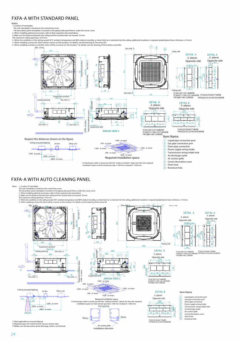
1. Location of nameplateThe unit nameplate is located on the control box cover.The decoration panel nameplate is located on the piping-side panel frame, under the corner cover.2. When installing optional accessories, refer to their respective documentation.3. Make sure the distance between the ceiling and the cassette does not exceed ·35·mm.The maximum ceiling opening is ·910·mm.4. When the conditions in the ceiling exceed 30°C ambient temperature and 80% relative humidity, or when fresh air is inducted into the ceiling, additional insulation is required (polyethylene foam, thickness ≥·10·mm). 5. When installing a sensor kit, there will be a sensor on this location. For details, see the drawing of the sensor kit.
Notes
55 840 55
840
FXFQ-B
2D121658
FXFA-A WITH AUTO CLEANING PANEL
35
210
C
5
ARROW VIEW C
340
0-67
5
4 - M8 M10
1 243
950
950
87 6
AB
213
Ø75
10
DETAIL A
780
710420
9
420
DETAIL B
121.5350
9554.5
54.5
81 100 100 85
96.5
DETAIL B
350121.5
DETAIL A
FCAG100/125/140BVEBFCAHG71/100/125/140HVEBFXFQ80/100/125BVEB
81 100 100 85
8010
010
080
54.554.5 96.5
25.4
121.
535
0
95
6753
121.
5 25.4
350
8010
010
080
96.5
96.5
53
FCAG35/50/60/71BVEBFXFQ20/25/32/40/50/63BVEB
FCAG100/125/140BVEBFCAHG71/100/125/140HVEBFXFQ80/100/125BVEB
A
B
860-910
860-
910
35
10° 10°
256(*3)(*2) (*1)
·1500· or more·2000· or more
·4000· or more
Ceiling-mounted lightingOther unitAir fan
(*1)Not applicable to recessed lighting.(*2)Required space for entering with vacuum cleaner tube.(*3)Make sure the decoration panel discharge outlet is not blocked.
·1500· or more·200· or more
·200· or more
·1500· or more
·1500· or more
·1500· or more
Required installation spaceIf a discharge outlet is closed up with the "sealing member" option kit, then the required
installation space on that (closed up) side is ·500·mm instead of ·1500·mm.
Air suction grille
Installation direction
Dust opening
PipingPiping 10987654321
Corner decoration cover
Knockout hole.Drain hose
Drain pipe connection
Liquid pipe connection portGas pipe connection port
Air suction grilleAir discharge outletTransmission wiring intake holePower supply wiring intake
Item Name
Opposite side
Opposite side·2· places
·2· placesCeiling opening
Suspension position
Ceili
ng o
peni
ngSusp
ensi
on p
ositi
on
·300· or less
See note ·3·.
See
note
·3·.
See note ·3·. See note ·3·.
Requ
ired
inst
alla
tion
spac
e·2
700·
or m
ore
See note ·5·. Drain side
Piping side
Opposite side·2· places
Opposite side·2· places
677
Suspension bolt
Adj
usta
ble
OR 330280
190
230
AA
4090
255
FCAG35/50/60/71BVEBFXFQ20/25/32/40/50/63BVEB
1. Location of nameplateThe unit nameplate is located on the control box cover.The decoration panel nameplate is located on the piping-side panel frame, under the corner cover.2. When installing optional accessories, refer to their respective documentation.3. Make sure the distance between the ceiling and the cassette does not exceed ·35·mm.The maximum ceiling opening is ·910·mm.4. When the conditions in the ceiling exceed 30°C ambient temperature and 80% relative humidity, or when fresh air is inducted into the ceiling, additional insulation is required (polyethylene foam, thickness ≥·10·mm). 5. When installing a sensor kit, there will be a sensor on this location. For details, see the drawing of the sensor kit.
Notes
55 840 55
840
FXFQ-B
2D121658
Item Name1
23
4
5
67
89
10
35 35
130
C
5
ARROW VIEW C
340
0-67
517
510
40 280
330
110 15
0
4 - M8 M10
1 243
950
950
87 6
AB
213
Ø75
10
A
DETAIL A
780
710
860-910
420
860-
910
9
420
B
DETAIL B
121.5350
9554.5
54.5
81 100 100 85
96.5
DETAIL B
350121.5
DETAIL A
81 100 100 85
8010
010
080
54.554.5 96.5
25.4
121.
535
0
95
6753
121.
5 25.4
350
8010
010
080
96.5
96.5
6753
·300· or less
Suspension position
Ceiling opening See note ·3·.
Susp
ensi
on p
ositi
on
Ceili
ng o
peni
ngSe
e no
te ·3
·.
·1500· or more·200· or more
·200· or more
·1500· or more
·1500· or more
·1500· or more
Required installation space·1500· or more
·2000· or more·4000· or more
If a discharge outlet is closed up with the "sealin g member" option kit, then the requiredinstallation space on that (closed up) side is ·500·mm instead of ·1500·mm.
Respect the distances shown on the �gure.Ceiling-mounted lighting Other unitAir fan
See note ·5·.
See note ·6·.
Drain side
Piping side
Opposite side·2· places
Opposite side·2· places
FCAG35/50/60/71BVEBFXFQ20/25/32/40/50/63BVEB
FCAG100/125/140BVEBFCAHG71/100/125/140HVEBFXFQ80/100/125BVEB
FCAG100/125/140BVEBFCAHG71/100/125/140HVEBFXFQ80/100/125BVEB
FCAG35/50/60/71BVEBFXFQ20/25/32/40/50/63BVEB
Opposite side·2· places
Opposite side·2· places
Gas pipe connection portLiquid pipe connection port
Drain pipe connection
Air suction grille
Drain hoseKnockout hole.
Power supply wiring intakeTransmission wiring intake holeAir discharge outlet
Corner decoration cover
See note ·3·. See note ·3·.
Requ
ired
inst
alla
tion
spac
e
Adj
usta
ble
Suspension boltOR
55 55840
1. Location of nameplate The unit nameplate is located on the control box cover. The decoration panel nameplate is located on the piping-side panel frame, under the corner cover.2. When installing optional accessories, refer to their respective documentation.3. Make sure the distance between the ceiling and the cassette does not exceed ·35·mm.The maximum ceiling opening is ·910·mm.4. When the conditions in the ceiling exceed 30°C ambient temperature and 80% relative humidity, or when fresh air is inducted into the ceiling, additional insulation is required (polyethylene foam, thickness ≥·10·mm)5. When installing a sensor kit, there will be a sensor on this location. For details, see the drawing of the sensor kit.6. When installing a wireless controller, there will be a receiver on this location. For details, see the drawing of the wireless controller.
Notes
840
·270
0· o
r mor
e
AA
FXFQ-B
2D121655
2D121655
FXFA-A WITH STANDARD PANEL
25
Item Name1
2
3
4
5
6
7
8
9
10
35 35
172
C
5
ARROW VIEW C
340
0-67
5
4 - M8 M10
1 243
950
950
87 6
AB
213
Ø75
10
DETAIL A
780
710
420
9
420
DETAIL B
121.5350
9554.5
54.5
81 100 100 85
96.5
DETAIL B
350121.5
DETAIL A
81 100 100 85
8010
010
080
54.554.5 96.5
25.4
121.
535
0
95
6753
121.
5 25.4
350
8010
010
080
96.5
96.5
6753
·300· or less
Suspension position
Ceiling opening See note ·3·.
Susp
ensi
on p
ositi
on
Ceili
ng o
peni
ngSe
e no
te ·3
·.
·1500· or more·200· or more
·200· or more
·1500· or more
·1500· or more
·1500· or more
Required installation space
·1500· or more·2000· or more
·4000· or more
If a discharge outlet is closed up with the "sealing member" option kit, then the requiredinstallation space on that (closed up) side is ·500·mm instead of ·1500·mm.
Respect the distances shown on the �gure.Ceiling-mounted lighting Other unitAir fan
See note ·5·.
See note ·6·.
Drain side
Piping side
Opposite side·2· places
Opposite side·2· places
FCAG35/50/60/71BVEBFXFQ20/25/32/40/50/63BVEBFCAG100/125/140BVEB
FCAHG71/100/125/140HVEBFXFQ80/100/125BVEB
FCAG100/125/140BVEBFCAHG71/100/125/140HVEBFXFQ80/100/125BVEB
FCAG35/50/60/71BVEBFXFQ20/25/32/40/50/63BVEB
Opposite side·2· places
Opposite side·2· places
Gas pipe connection portLiquid pipe connection port
Drain pipe connection
Drain hoseKnockout hole.
Power supply wiring intakeTransmission wiring intake holeAir discharge outlet
Corner decoration cover
See note ·3·. See note ·3·.
Requ
ired
inst
alla
tion
spac
e
Adj
usta
ble
Suspension boltOR
A
B
860-910
860-
910
Flat grille assembly
152
192
280330
217 A
A
45
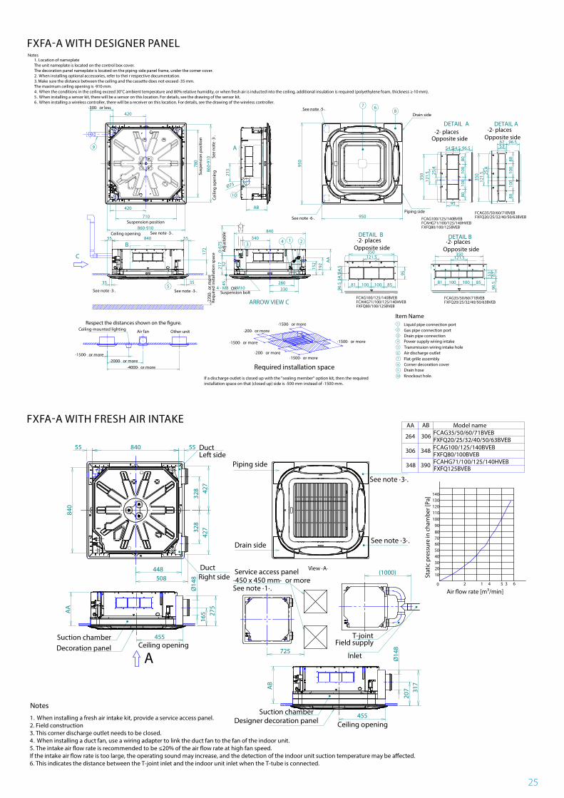
1. Location of nameplateThe unit nameplate is located on the control box cover.The decoration panel nameplate is located on the piping-side panel frame, under the corner cover.2. When installing optional accessories, refer to thei r respective documentation.3. Make sure the distance between the ceiling and the cassette does not exceed ·35·mm.The maximum ceiling opening is ·910·mm.4. When the conditions in the ceiling exceed 30°C ambient temperature and 80% relative humidity, or when fresh air is inducted into the ceiling, additional insulation is required (polyethylene foam, thickness ≥·10·mm). 5. When installing a sensor kit, there will be a sensor on this location. For details, see the drawing of the sensor kit.6. When installing a wireless controller, there will be a receiver on this location. For details, see the drawing of the wireless controller.
Notes
55 840 55840
·270
0· o
r mor
e
52
FXFQ-B
2D121703
Notes
1. When installing a fresh air intake kit, provide a service access panel.2. Field construction3. This corner discharge outlet needs to be closed.4. When installing a duct fan, use a wiring adapter to link the duct fan to the fan of the indoor unit.5. The intake air �ow rate is recommended to be ≤20% of the air �ow rate at high fan speed.If the intake air �ow rate is too large, the operating sound may increase, and the detection of the indoor unit suction temperature may be a�ected.6. This indicates the distance between the T-joint inlet and the indoor unit inlet when the T-tube is connected.
328
328
427
427
448508
840
Duct
Duct
Left side
Right side
Piping side
Drain side
See note ·3·.
See note ·3·.
84055 55
Decoration panelSuction chamber
Ceiling opening
A
654 32 10
140130120110100908070605040302010
Air �ow rate [m³/min]
Stat
ic p
ress
ure
in c
ham
ber [
Pa]
725
·450 x 450 mm· or moreSee note ·1·.
(1000)
Field supply
Inlet
Service access panel
T-joint455
Ø14
816
5 275
AA
AB
348
390
Model name
FCAG100/125/140BVEB
FCAHG71/100/125/140HVEB
306 FCAG35/50/60/71BVEB
View ·A·
FXFQ20/25/32/40/50/63BVEB
FXFQ125BVEB
FXFQ80/100BVEB
Suction chamber
Ceiling opening
Ø14
8
Designer decoration panel
AB
AA
306
348
264
317
207
455
FXFQ-B
3D121741
FXFA-A WITH DESIGNER PANEL
FXFA-A WITH FRESH AIR INTAKE
26
FXZA-A
FXZA-A
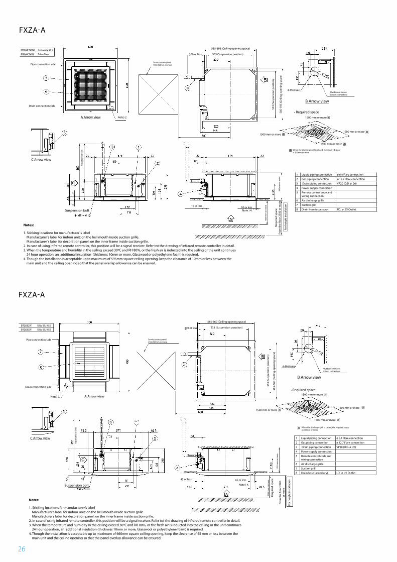
Notes:
1. Sticking locations for manufacturer`s label Manufacturer`s label for indoor unit: on the bell mouth inside suction grille. Manufacturer`s label for decoration panel: on the inner frame inside suction grille.2. In case of using infrared remote controller, this position will be a signal receiver. Refer tot the drawing of infrared remote controller in detail.3. When the temperature and humidity in the ceiling exceed 30ºC and RH 80%, or the fresh air is inducted into the ceiling or the unit continues 24 hour operation, an additional insulation (thickness 10mm or more, Glasswool or polyethylene foam) is required.4. Though the installation is acceptable up to maximum of 595mm square ceiling opening, keep the clearance of 10mm or less between the main unit and the ceiling opening so that the panel overlap allowance can be ensured.
Decoration panel
Pipe connection side
Drain connection side
Note) 2.
Adju
stab
le (0
-630
)
C Arrow view
A Arrow view
Suspension bolt
B Arrow view
300 or less
10 or lessNote ) 4.
1500 mm or more
1500 mm or more
1500 mm or more
1500 mm or more
1500
mm
or m
ore
300
mm
or m
ore
Service access panel450x450mm or more
533 (Suspension position)
585-595 (Ceiling opening space)
Outdoor air intake (direct connection)
• Required space
Requ
ired
spac
e 53
3 (S
uspe
nsio
n po
sitio
n)
585-
595
(Cei
ling
open
ing
spac
e)
4-M4 Hole
When the discharge grill is closed, the required space is 200mm or more
From
the
�oor
250
0 or
mor
e
For h
eigh
t ins
talla
tion
3D082052
10 or less
FXZQ-AFresh white N9.5BYFQ60C2W1W
BYFQ60C2W1S Daikin Silver
1 Liquid piping connection ø 6.4 Flare connection
2 Gas piping connection ø 12.7 Flare connection
3 Drain piping connection VP20 (O.D. ø 26)
4 Power supply connection
5 Remote control code and wiring connection
6 Air discharge grille
7 Suction grill
8 Drain hose (accessory) I.D. ø 25 Outlet
Notes:
1. Sticking locations for manufacturer’s label Manufacturer’s label for indoor unit: on the bell mouth inside suction grille. Manufacturer’s label for decoration panel: on the inner frame inside suction grille.2. In case of using infrared remote controller, this position will be a signal receiver. Refer tot the drawing of infrared remote controller in detail.3. When the temperature and humidity in the ceiling exceed 30ºC and RH 80%, or the fresh air is inducted into the ceiling or the unit continues 24 hour operation, an additional insulation (thickness 10mm or more, Glasswool or polyethylene foam) is required.4. Though the installation is acceptable up to maximum of 660mm square ceiling opening, keep the clearance of 45 mm or less between the main unit and the ceiling opening so that the panel overlap allowance can be ensured.
Decoration panel
Pipe connection side
Drain connection side
Note) 2.
Adju
stab
le (0
-645
)
C Arrow view
A Arrow view
Suspension bolt
B Arrow view
300 or less
45 or less 45 or less
Note ) 4.
1500 mm or more
1500 mm or more
1500 mm or more
1500 mm or more
1500
mm
or m
ore
295
mm
or m
ore
Service access panel450x450mm or more
533 (Suspension posotion)
585-660 (Ceiling opening space)
Outdoor air intake(direct connection)
• Required space
Requ
ired
spac
e 53
3 (S
uspe
nsio
n po
sotio
n)
585-
660
(Cei
ling
open
ing
spac
e)
4-M4 Hole
When the discharge grill is closed, the required space is 200mm or more
From
the
�oor
250
0 or
mor
e
For h
eigh
t ins
talla
tion
3D082161A
1 Liquid piping connection ø 6.4 Flare connection
2 Gas piping connection ø 12.7 Flare connection
3 Drain piping connection VP20 (O.D. ø 26)
4 Power supply connection
5 Remote control code and wiring connection
6 Air discharge grille
7 Suction grill
8 Drain hose (accessory) I.D. ø 25 Outlet
27
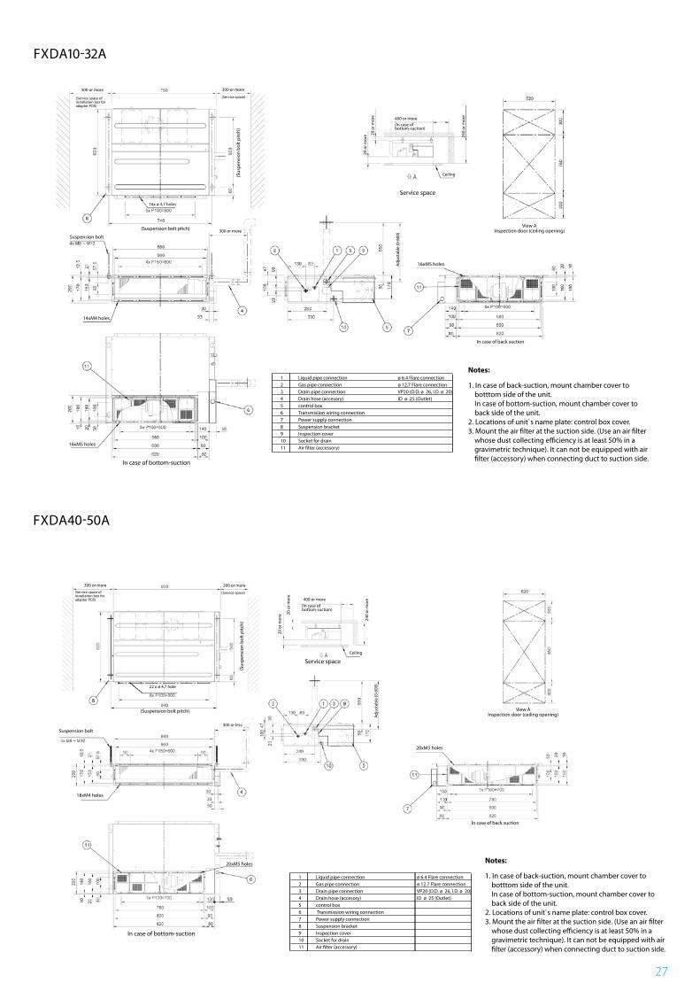
FXDA10-32A
FXDA40-50A
FXDQ15-32A
1 Liquid pipe connection ø 6.4 Flare connection2 Gas pipe connection ø 12.7 Flare connection3 Drain pipe connection VP20 (O.D. ø 26, I.D. ø 20)4 Drain hose (accesory) ID ø 25 (Outlet)5 control box6 Transmisiion wiring connection7 Power supply connection8 Suspension bracket9 Inspection cover 10 Socket for drain11 Air �lter (accessory)
In case of bottom-suction
In case of back suction
14xM4 holes
16xM5 holes
Suspension bolt
(Suspension bolt pitch)
16x ø 4,7 holes
300 or more(S
usp
ensi
on b
olt p
itch)
300 or more300 or more
400 or more
20 o
r mor
e 240
or m
ore
Ceiling
Service space
20 o
r mor
e
(Service space)
16xM5 holesAdj
usta
ble
(0-6
00)
View AInspection door (ceiling opening)
(In case of bottom-suction)
(Service space ofinstallation box foradapter PCB)
3D081435
Notes:
1. In case of back-suction, mount chamber cover to botttom side of the unit. In case of bottom-suction, mount chamber cover to back side of the unit.2. Locations of unit`s name plate: control box cover.3. Mount the air �lter at the suction side. (Use an air �lter whose dust collecting e�ciency is at least 50% in a gravimetric technique). It can not be equipped with air �lter (accessory) when connecting duct to suction side.
FXDQ40-50A
1 Liquid pipe connection ø 6.4 Flare connection2 Gas pipe connection ø 12.7 Flare connection3 Drain pipe connection VP20 (O.D. ø 26, I.D. ø 20)4 Drain hose (accesory) ID ø 25 (Outlet)5 control box6 Transmission wiring connection7 Power supply connection8 Suspension bracket9 Inspection cover 10 Socket for drain11 Air �lter (accessory)
In case of bottom-suction
In case of back suction
18xM4 holes
Suspension bolt
(Suspension bolt pitch)
22 x ø 4,7 hole
300 or less
(Sus
pen
sion
bol
t pitc
h)
300 or more300 or more
400 or more
20 o
r mor
e
240
or m
ore
Ceiling
Service space
20 o
r mor
e
(Service space)
20xM5 holes
Adj
usta
ble
(0-6
00)
View AInspection door (ceiling opening)
(In case of bottom-suction)
(Service space ofinstallation box foradapter PCB)
3D081436
Notes:
1. In case of back-suction, mount chamber cover to botttom side of the unit. In case of bottom-suction, mount chamber cover to back side of the unit.2. Locations of unit`s name plate: control box cover.3. Mount the air �lter at the suction side. (Use an air �lter whose dust collecting e�ciency is at least 50% in a gravimetric technique). It can not be equipped with air �lter (accessory) when connecting duct to suction side.
20xM5 holes
28
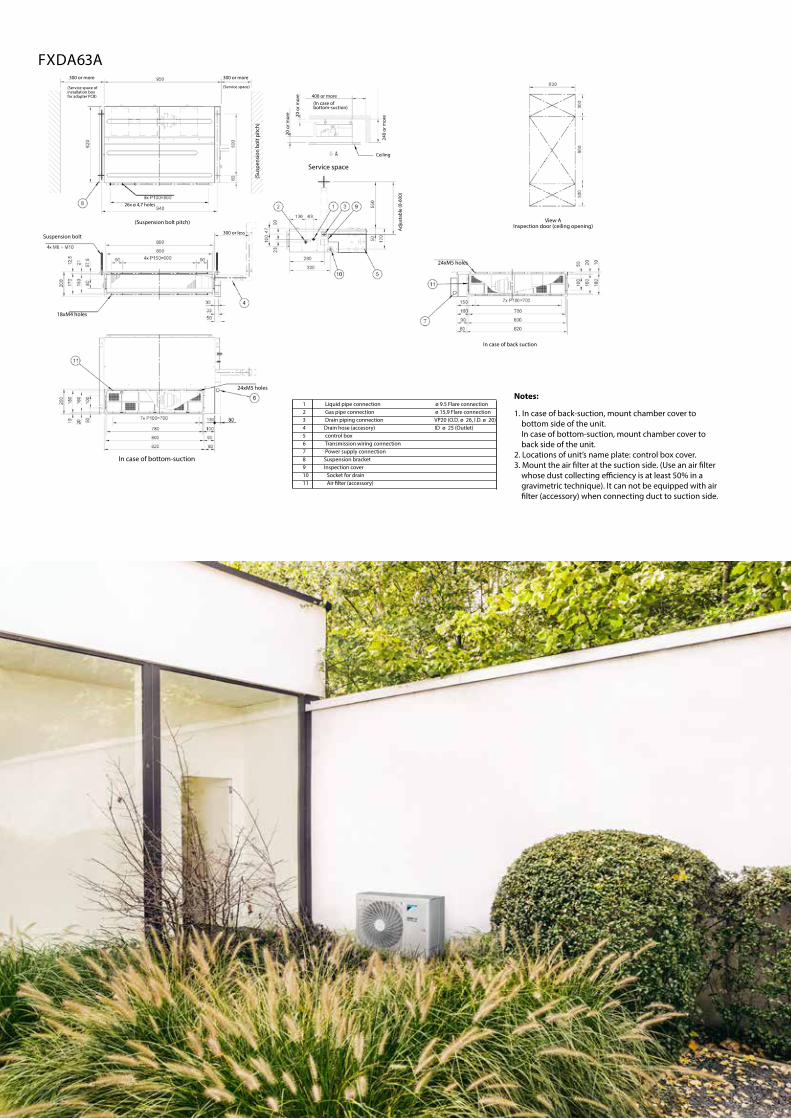
FXDQ63A
1 Liquid pipe connection ø 9.5 Flare connection2 Gas pipe connection ø 15,9 Flare connection3 Drain piping connection VP20 (O.D. ø 26, I.D. ø 20)4 Drain hose (accesory) ID ø 25 (Outlet)5 control box6 Transmission wiring connection7 Power supply connection8 Suspension bracket9 Inspection cover 10 Socket for drain11 Air �lter (accessory)
In case of bottom-suction
In case of back suction
18xM4 holes
24xM5 holes
Suspension bolt
(Suspension bolt pitch)
26x ø 4,7 holes
300 or less
(Sus
pens
ion
bolt
pitc
h)
300 or more300 or more
400 or more
20 o
r mor
e
240
or m
ore
Ceiling
Service space
20 o
r mor
e
(Service space)
24xM5 holes
Adju
stab
le (0
-600
)
View AInspection door (ceiling opening)
(In case of bottom-suction)
(Service space ofinstallation box for adapter PCB)
3D081441
Notes:
1. In case of back-suction, mount chamber cover to bottom side of the unit. In case of bottom-suction, mount chamber cover to back side of the unit.2. Locations of unit’s name plate: control box cover.3. Mount the air �lter at the suction side. (Use an air �lter whose dust collecting e�ciency is at least 50% in a gravimetric technique). It can not be equipped with air �lter (accessory) when connecting duct to suction side.
126 P.C.D.
ARROW VIEW A
ARROW VIEW A
Knockout hole.
500 or moreService space
300
or m
ore
Serv
ice
spac
e
Item Name Description
Liquid pipe connection port
Gas pipe connection port
Drain pipe connection
Wiring connection
Power supply connection
Drain outlet
Air filter
Air suction side
Air discharge side
Nameplate
Ø6.35 flared connection
Ø12.70 flared connection
VP20 (OD Ø26, ID Ø20)
VP20 (OD Ø26, ID Ø20)
//
////
Fresh air intake position
Suspension bolt
Suspension position
Susp
ensi
on p
ositi
on
KE
KDKF
KK
4-M4 (CLASS 2)
140
Ø100( )
170 550 69
4034250
65100
178
245
38 109
322802x140=
365
130
2x65
=
25 800
301KJ KC KH
5011
0
210
179.2 50
KG
95 210
145 150 145504
2604x65=588
630
KA
KB
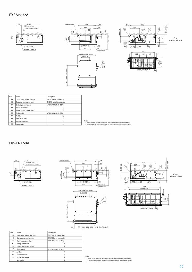
1. When installing optional accessories, refer to their respective documentation.
2. The ceiling depth varies according to the documentation of the specific system.
Notes
KA
KB
KC
KD
KE
KF
KG
KH
KJ
KK
FXSQ15-32A
3D094888A
FXDA63A
126 P.C.D.
ARROW VIEW A
ARROW VIEW A
Knockout hole.
500 or moreService space
300
or m
ore
Serv
ice
spac
e
5- Ø 4.7 HOLE
140
170 Ø100( )
4-M4 (CLASS 2)
492
700
65100
178
245
50
69
40
38 109
4203x140=515
32
130
2x65
=
25 800301
179 50 5011
0
210
630
3906x65=738
42 155 130 130 120
5904x145=654
95 210
Item Name Description
Liquid pipe connection port
Gas pipe connection port
Drain pipe connection
Wiring connection
Power supply connection
Drain outlet
Air filter
Air suction side
Air discharge side
Nameplate
Ø6.35 flared connection
Ø12.70 flared connection
VP20 (OD Ø26, ID Ø20)
VP20 (OD Ø26, ID Ø20)
//
////
Fresh air intake position
Suspension bolt
Suspension position
Susp
ensi
on p
ositi
on
KC KE
KDKF
KG
KHKJ
KA
KB
KK
1. When installing optional accessories, refer to their respective documentation.
2. The ceiling depth varies according to the documentation of the specific system.
Notes
KA
KB
KC
KD
KE
KF
KG
KH
KJ
KK
FXSQ40-50A
3D094919A
29
126 P.C.D.
ARROW VIEW A
ARROW VIEW A
Knockout hole.
500 or moreService space
300
or m
ore
Serv
ice
spac
e
Item Name Description
Liquid pipe connection port
Gas pipe connection port
Drain pipe connection
Wiring connection
Power supply connection
Drain outlet
Air filter
Air suction side
Air discharge side
Nameplate
Ø6.35 flared connection
Ø12.70 flared connection
VP20 (OD Ø26, ID Ø20)
VP20 (OD Ø26, ID Ø20)
//
////
Fresh air intake position
Suspension bolt
Suspension position
Susp
ensi
on p
ositi
on
KE
KDKF
KK
4-M4 (CLASS 2)
140
Ø100( )
170 550 69
4034250
65100
178
245
38 109
322802x140=
365
130
2x65
=
25 800
301KJ KC KH
5011
0
210
179.2 50
KG
95 210
145 150 145504
2604x65=588
630
KA
KB
1. When installing optional accessories, refer to their respective documentation.
2. The ceiling depth varies according to the documentation of the specific system.
Notes
KA
KB
KC
KD
KE
KF
KG
KH
KJ
KK
FXSQ15-32A
3D094888A
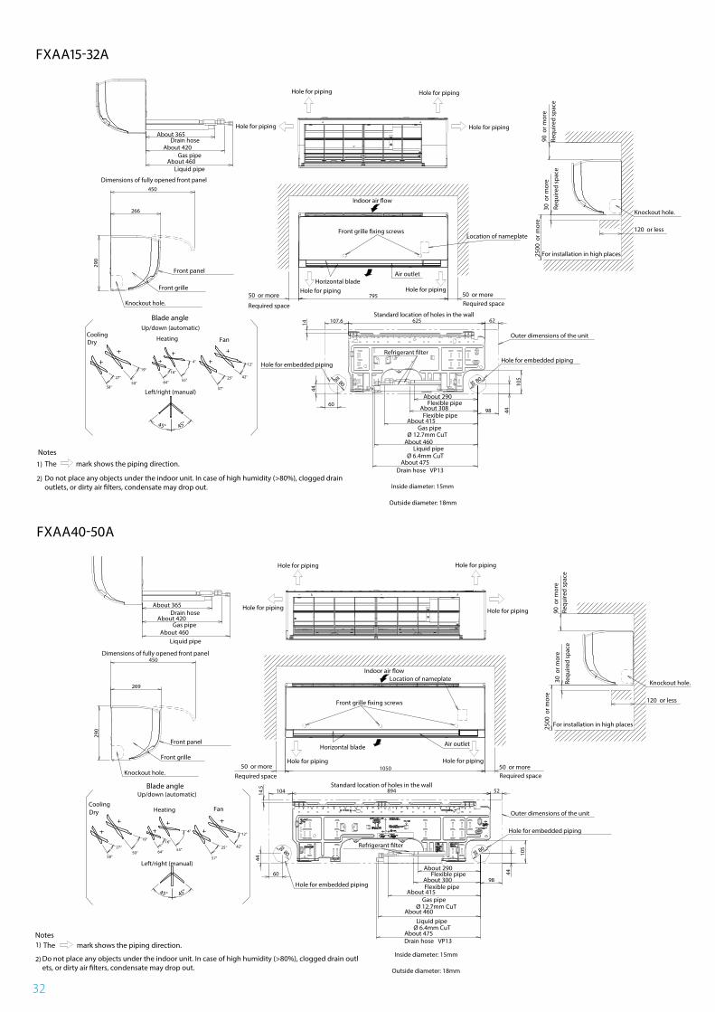
FXSA15-32A
126 P.C.D.
ARROW VIEW A
ARROW VIEW A
Knockout hole.
500 or moreService space
300
or m
ore
Serv
ice
spac
e
5- Ø 4.7 HOLE
140
170 Ø100( )
4-M4 (CLASS 2)
492
700
65100
178
245
50
69
40
38 109
4203x140=515
32
130
2x65
=
25 800301
179 50 5011
0
210
630
3906x65=738
42 155 130 130 120
5904x145=654
95 210
Item Name Description
Liquid pipe connection port
Gas pipe connection port
Drain pipe connection
Wiring connection
Power supply connection
Drain outlet
Air filter
Air suction side
Air discharge side
Nameplate
Ø6.35 flared connection
Ø12.70 flared connection
VP20 (OD Ø26, ID Ø20)
VP20 (OD Ø26, ID Ø20)
//
////
Fresh air intake position
Suspension bolt
Suspension position
Susp
ensi
on p
ositi
on
KC KE
KDKF
KG
KHKJ
KA
KB
KK
1. When installing optional accessories, refer to their respective documentation.
2. The ceiling depth varies according to the documentation of the specific system.
Notes
KA
KB
KC
KD
KE
KF
KG
KH
KJ
KK
FXSQ40-50A
3D094919A
FXSA40-50A
30
126 P.C.D.
ARROW VIEW A
ARROW VIEW A
Knockout hole.
500 or moreService space
300
or m
ore
Serv
ice
spac
e
170 Ø100( )
4 x M4 (CLASS 2)
65100
178
24514
0
50792
1000 6940
38 109
7305x146=815
32 5011
0
210
130
2x65
=
301
80025
179 50
71511x65=
1038
630
42 135 125 98 117 135 125 100 8-Ø4.7 HOLE
8906x145=954
95 210
Item Name Description
Liquid pipe connection port
Gas pipe connection port
Drain pipe connection
Wiring connection
Power supply connection
Drain outlet
Air filter
Air suction side
Air discharge side
Nameplate
Ø9.52 flared connection
Ø15.90 flared connection
VP20 (OD Ø26, ID Ø20)
VP20 (OD Ø26, ID Ø20)
//
////
Fresh air intake position
Suspension bolt
Suspension position
Susp
ensi
on p
ositi
on
KC KE
KDKF
KGKG
KHKJ
KA
KB
KK
1. When installing optional accessories, refer to their respective documentation.
2. The ceiling depth varies according to the documentation of the specific system.
Notes
KA
KB
KC
KD
KE
KF
KG
KH
KJ
KK
FXSQ63-80A
3D094916A
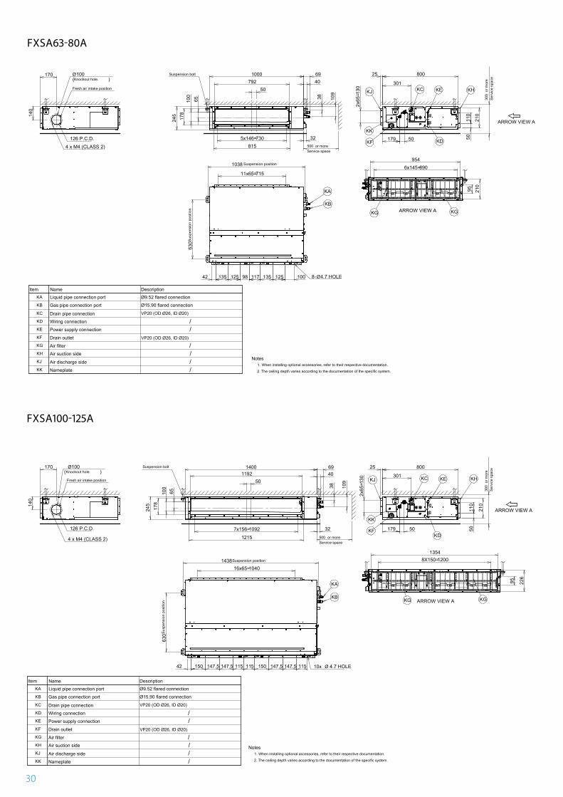
FXSA63-80A
170
140
Ø100( )
126 P.C.D.
4 x M4 (CLASS 2)
65100
245
178
501192
1400 6940
38 109
32
1215
10927x156= 179 50
301
80025
130
2x65
=
5011
0
210
104016x65=1438
630
42 150 147.5 147.5 115 115 150 147.5 147.5 115 10x Ø 4.7 HOLE
ARROW VIEW A
ARROW VIEW A
12008X150=1354
95 226
Knockout hole.
500 or moreService space
300
or m
ore
Serv
ice
spac
e
Item Name Description
Liquid pipe connection port
Fresh air intake position
Suspension bolt
KC KE
KDKF
KGKG
KHKJ
KA
KB
KK
Gas pipe connection port
Drain pipe connection
Wiring connection
Power supply connection
Drain outlet
Air filter
Air suction side
Air discharge side
Nameplate
Ø9.52 flared connection
Ø15.90 flared connection
Suspension position
VP20 (OD Ø26, ID Ø20)
VP20 (OD Ø26, ID Ø20)
Susp
ensi
on p
ositi
on
//
////
1. When installing optional accessories, refer to their respective documentation.
2. The ceiling depth varies according to the documentation of the specific system.
Notes
KA
KB
KC
KD
KE
KF
KG
KH
KJ
KK
FXSQ100-125A
3D094917A
FXSA100-125A
31
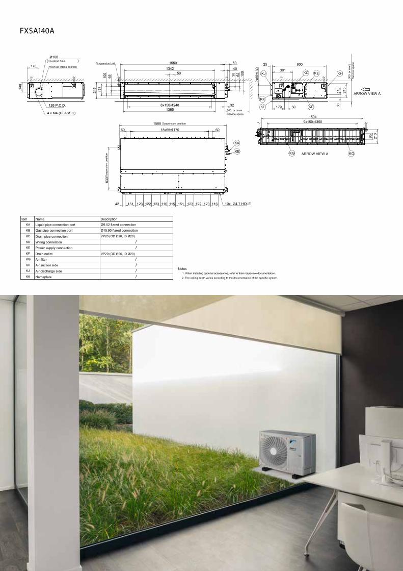
170
140
Ø100( )
126 P.C.D.
4 x M4 (CLASS 2)
40
38 62 109 301
80025
130
2x65
=
5011
0
210
10x Ø4.7 HOLE
ARROW VIEW A
ARROW VIEW A
Item Name Description
Liquid pipe connection port
Knockout hole.
500 or moreService space
300
or m
ore
Serv
ice
spac
e
Fresh air intake position
501342
1550 69
65100
178
245
Suspension bolt
12488x156=1365
32 179 50
KC KE
KDKF
KGKG
KHKJ
KA
KB
KK
Gas pipe connection port
Drain pipe connection
Wiring connection
Power supply connection
Drain outlet
Air filter
Air suction side
Air discharge side
Nameplate
Ø9.52 flared connection
Ø15.90 flared connection
Suspension position
VP20 (OD Ø26, ID Ø20)
VP20 (OD Ø26, ID Ø20)
60 117018x65= 60
1588
630S
uspe
nsio
n po
sitio
n
42 151 123 122 123 116 115 151 123 122 123 116
95 210
13509x150=1504
//
////
1. When installing optional accessories, refer to their respective documentation.
2. The ceiling depth varies according to the documentation of the specific system.
Notes
KA
KB
KC
KD
KE
KF
KG
KH
KJ
KK
FXSQ140A
3D094928A
FXSA140A
32
290
450
894 52104
44
Requ
ired
spac
e90
or m
ore
30 o
r mor
e
Requ
ired
spac
e
2500
or m
ore
120 or less
50 or moreRequired space
50 or more
Required space
Horizontal blade
1050
Indoor air �ow
Front grille �xing screws
Dimensions of fully opened front panel
14.5
98
� 80
105
60
44
�80
Outer dimensions of the unit
Standard location of holes in the wall
Hole for embedded piping
Hole for embedded piping
The mark shows the piping direction.
Do not place any objects under the indoor unit. In case of high humidity (>80%), clogged drain outlets, or dirty air �lters, condensate may drop out.
1)
2)
Notes
Refrigerant �lter
Liquid pipe
Liquid pipe
Gas pipeØ 12.7mm CuT
Ø 6.4mm CuT
Drain hose VP13
Inside diameter: 15mm
Outside diameter: 18mm
Knockout hole.
Knockout hole.
Flexible pipe
Flexible pipe
Front grille
Front panel Air outlet
Blade angleUp/down (automatic)
CoolingDry Heating Fan
27°
58°50°
19°
64°
16°
55°
4°
57°
25° 42°
12°
Left/right (manual)
Location of nameplate269
Hole for piping
Hole for piping
Hole for piping
Hole for piping
Hole for pipingHole for piping
45° 45° About 415
About 290
About 300
About 460
About 475
Gas pipe About 460
Drain hose About 420
About 365
For installation in high places
FXAQ40-50A
3D111369
FXAA40-50A
290
450
625 62107.6
44
Requ
ired
spac
e90
or m
ore
30 o
r mor
e
Requ
ired
spac
e
2500
or m
ore
120 or less
50 or moreRequired space
50 or more
Required space
Horizontal blade
795
Indoor air �ow
Front grille �xing screws
Dimensions of fully opened front panel
14
98
� 80
105
60
44
�80
Outer dimensions of the unit
Standard location of holes in the wall
Hole for embedded pipingHole for embedded piping
The mark shows the piping direction.
Do not place any objects under the indoor unit. In case of high humidity (>80%), clogged drainoutlets, or dirty air �lters, condensate may drop out.
1)
2)
Notes
Refrigerant �lter
Drain hose
Gas pipe
Liquid pipe
Liquid pipe
Gas pipeØ 12.7mm CuT
Ø 6.4mm CuT
Drain hose VP13
Inside diameter: 15mm
Outside diameter: 18mm
Knockout hole.
Knockout hole.
Flexible pipe
Flexible pipe
Front grille
Front panel Air outlet
29
Blade angleUp/down (automatic)
CoolingDry Heating Fan
27°
58°50°
19°
64°
16°
55°
4°
57°
25° 42°
12°
Left/right (manual)
45° 45°
266
Hole for piping Hole for piping
Hole for piping
Hole for pipingHole for piping
Hole for piping
Location of nameplate
About 475
About 460
About 415
About 308
About 290
About 365
About 420
About 460
For installation in high places
FXAQ15-32A
3D111370
FXAA15-32A
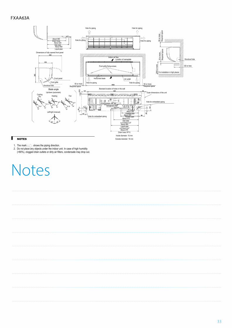
Notes
33
FXAQ63A
3D111368
NOTES
1. The mark shows the piping direction. 2. Do not place any objects under the indoor unit. In case of high humidity(>80%), clogged drain outlets or dirty air filters, condensate may drop out.
About 365
About 420
About 460Liquid pipe
Dimensions of fully opened front panel
Gas pipe
Drain hose
Hole for piping Hole for piping
Hole for piping Hole for piping
Location of nameplate
Standard location of holes in the wall
Horizontal blade
Hole for piping
Hole for embedded piping
Front panel
50 or moreRequired space
Up/down (automatic)
Heating
Left/right (manual)
Fan
Blade angle
Front grilleKnockout hole
CoolingDry
Required space
Outer dimensions of the unit
Hole for embedded piping
50 or more
Knockout hole
Requ
ired s
pace
Requ
ired s
pace
90 or
mor
e30
or m
ore
2500
or m
ore 120 or less
For installation in high places
Air outlet
Hole for piping
USE TAPE MEASURE AS SHOWN
Position the end oftape measure at
HOLE FOR CONCRETE WALL HOLE FOR CONCRETE WALL
PIPING HOLE CENTER: 90 mm DOWN
100mm TOUNIT RIGHTSIDE FACE
Liquid pipe end
TO UNIT OUTLINE
UNIT WIDTH: 1050 mm
IF FIXINGUNIT TOTHIS PLATEWITH SCREWFIX THISPLATE TOTHE WALLWITH SCREW
UNIT HEIGHT: 290 mm
525mm TO THE RIGHT AND LEFT145mm UP AND DOWN
Gas pipe end
unit center
PLACE A LEVEL125mm TO UNITLEFT
SIDE FACE
PIPING HOLE CENTER83mm TO THE LEFT
PIPING HOLECENTER100mm TOTHE RIGHT
About 290Flexible pipeFlexible pipe
About 300
About 415
About 460
About 475
Liquid pipeø 9.5mm CuT
Gas pipeø 15.9mm CuT
Drain hose VP13Inside diameter: 15 mm
Outside diameter: 18 mm
Refrigerant filter
Indoor air flow
Front grille fixing screws
FXAA63A

Notes
34

Notes
35

www.daikin.eu/building-a-circular-economy
Through innovation › Equip our VRV 5 range with the lower GWP refrigerant R-32
› Offer high real-world seasonal efficiencies › Deploy unique auto cleaning filters to maximise efficiency 24/7
Through a circular economy › Embrace Certified Reclaimed Refrigerant Allocation to reuse more refrigerant
› Increase recovered refrigerant returns › Reuse refrigerant for maintenance with our refrigerant recycling machine
Determined to reduce our environmental footprint, we aim to be CO₂-neutral by 2050.A circular economy, innovation and smart use – these are the stepping stones on our path. The time to act is now. Join us in creating a sustainable future for HVAC-R.
Through smart use › Rigorously follow up on energy consumption via the Daikin Cloud Service
› Factor in experts’ advice to continuously optimise system efficiency
› Enable predictive maintenance to ensure optimum operation and uptime
› Prevent energy waste with smart key cards and sensors
Creating a sustainable future together
Sowing the seeds of climate protection with Daikin
FSC
ECPEN20 -210A 25/02/2020
The present publication is drawn up by way of information only and does not constitute an offer binding upon Daikin Europe N.V. Daikin Europe N.V. has compiled the content of this publication to the best of its knowledge. No express or implied warranty is given for the completeness, accuracy, reliability or fitness for particular purpose of its content and the products and services presented therein. Specifications are subject to change without prior notice. Daikin Europe N.V. explicitly rejects any liability for any direct or indirect damage, in the broadest sense, arising from or related to the use and/or interpretation of this publication. All content is copyrighted by Daikin Europe N.V.
Printed on non-chlorinated paper. Prepared by La Movida.
Daikin Europe N.V. Naamloze Vennootschap Zandvoordestraat 300 · 8400 Oostende · Belgium · www.daikin.eu · BE 0412 120 336 · RPR Oostende (Publisher)