Embed Size (px)
Citation preview
Vrije Universiteit Brussel
Design of a hydroformed metal blade for vertical-axis wind turbinesDominguez Fernandez, Diego; Pröhl, Marco; De Troyer, Tim; Werner, Markus; Runacres,MarkPublished in:Journal of Renewable and Sustainable Energy
DOI:10.1063/1.4928949
Publication date:2015
Document Version:Accepted author manuscript
Link to publication
Citation for published version (APA):Dominguez Fernandez, D., Pröhl, M., De Troyer, T., Werner, M., & Runacres, M. (2015). Design of ahydroformed metal blade for vertical-axis wind turbines. Journal of Renewable and Sustainable Energy, 7,[043135]. https://doi.org/10.1063/1.4928949
General rightsCopyright and moral rights for the publications made accessible in the public portal are retained by the authors and/or other copyright ownersand it is a condition of accessing publications that users recognise and abide by the legal requirements associated with these rights.
• Users may download and print one copy of any publication from the public portal for the purpose of private study or research. • You may not further distribute the material or use it for any profit-making activity or commercial gain • You may freely distribute the URL identifying the publication in the public portalTake down policyIf you believe that this document breaches copyright please contact us providing details, and we will remove access to the work immediatelyand investigate your claim.
Download date: 10. Nov. 2021

Design of a hydroformed metal blade for vertical-axis wind turbines
Diego Domınguez Fernandez,1, 2 Marco Prohl,3 Tim De Troyer,2 Markus Werner,3 and
Mark C. Runacres2
1)Area de Ingenierıa Aeroespacial, Universidad de Leon, Campus de Vegazana s/n,
24071 Leon, Spain
2)Department of Engineering Technology, Vrije Universiteit Brussel, Pleinlaan 2,
1050 Brussels, Belgiuma)
3)Fraunhofer Institute for Machine Tools and Forming Technology IWU,
Reichenhainer Straße 88, 09126 Chemnitz, Germany
(Dated: 29 July 2015)
Vertical-axis wind turbines (VAWTs) have experienced a renewed impulse during the
last few years, with important research efforts focused on them. This work explores
whether the global profitability of VAWTs can be improved through improved man-
ufacturing techniques. We studied how large-series production techniques from the
sheet-metal industry can be used to create blades of H-type Darrieus turbines. Blade
size and shape were determined via aerodynamic and structural analyses. The pro-
posed solution is based on the use of hydroforming manufacturing techniques with
metal sheets. Our estimations show that with the positive effects of a large-scale use
and production (economies of scale), such metal blades have a 90% reduction poten-
tial in their production costs compared to fibre-reinforced ones for single turbines.
Keywords: Vertical-axis wind turbines, blade manufacturing, cost analysis
a)Electronic mail: [email protected]
1
I. INTRODUCTION
Horizontal axis wind turbines (HAWTs) have been the focus of most of the wind energy
related research during the last few decades and represent the major portion of the installed
capacity. However, research work on vertical-axis wind turbines (VAWTs) continued in
parallel, usually focused in the small scale, where different configurations and approaches
have been proposed. It has been stated that VAWTs are suitable for electricity generation in
the conditions where traditional HAWTs are unable to give reasonable efficiencies, such as
turbulent winds with strong variations of the wind direction. Another important advantage
is the fact that VAWTs are omnidirectional, accepting wind from any direction without
any yawing mechanism1. Recent research has also shown that it is possible to increase the
global performance of VAWTs by erecting them in tight arrays with alternating directions
of rotation. A column of co-rotating VAWTs was estimated to provide a power increase of
50% to 100%, compared to the same number of isolated VAWTs2, confirming the validity of
the concept previously suggested by Dabiri 3 . In this manner, farms of VAWTs can achieve
a higher power output per unit land area (W/m2) and consequently a smaller footprint than
equivalent HAWT farms. Other options to increase the power output of VAWTs, such as
inlet guide-vanes4,5 have also been explored.
Yet despite all the recent advances, VAWTs are economically not yet competitive against
HAWTs6, due to their lower power coefficients. In this work we therefore focus on ways to
improve their global profitability, by investigating the use of low cost production technologies
together with the choice of the materials used for blade production. The blades of H-type
VAWTs, also known as giromills, are particularly suited to low-cost production, because of
their simple shape (no taper, no twist).
For a new blade with equal aerodynamic performance compared to existing blades, de-
creasing the manufacturing cost is a straightforward way to improve the return on invest-
ment. A low manufacturing cost is typically achieved by using large-series production tech-
nologies. It has recently been suggested that large farms of closely-spaced VAWTs could
achieve better power densities than the classic existing HAWT farms2,3. The market uptake
of this insight would require the use of very large volumes of turbines (and blades), thereby
increasing the need for large-series production technologies.
Of course, the choice of a manufacturing process that is suited for large-series production
2
strongly depends on the material to be used. Most wind turbine blades are currently made
of fibre-reinforced composites, which are quite costly (up to 30% of the whole turbine cost7).
Metal is sometimes used as an internal structural component in the blades of large HAWTs;
some small wind turbines have extruded aluminium blades. We argue that the use of metal
could facilitate the production process of the turbine blades, and would additionally have
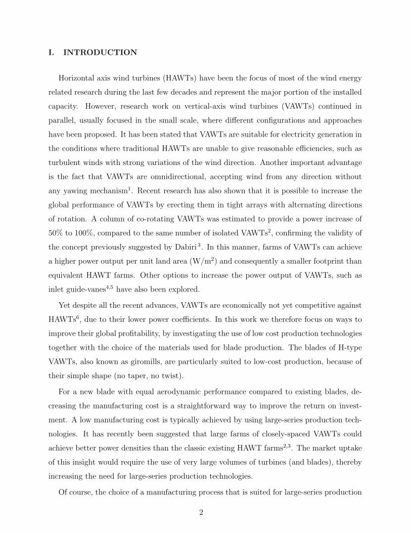
advantages with respect to issues like robustness, sustainability and recycling. The workflow
leading to the such a blade is represented in Fig. 1. If metal blades are to gain a larger share
of the market, they should lead to a decrease in the cost of energy by offering (at least) equal
aerodynamic performance, decreased cost (materials, manufacturing process) and increased
sustainability (energy for production, recycling, lifetime).
The aerodynamic performance of the blade is determined by its external shape and, to
a lesser degree, its surface roughness. In Sect. II we discuss the overall dimensioning of the
rotor and the aerodynamic design of the blades, including the profile choice. In Sect. III we
investigate the structural aspects of the metal blade, in particular deformation, stress and
fatigue. In Sect. IV we propose suitable production techniques so that, at sufficiently large
production volumes, metal blades are significantly cheaper than composite blades.
FIG. 1. Workflow followed for the analysis and development of the low-cost blades.
II. AERODYNAMIC ANALYSIS OF VAWT BLADES
A. Selected method
The aerodynamics of a VAWT is quite different from a HAWT (see e.g. Manwell, Mc-
Gowan, and Rogers 8) and in general more complicated. The relative motion of the blades
3
with respect to the freestream velocity can cause dynamic stall, particularly at low tip-speed
ratios. The struts have a significant influence both on the performance of the turbine and
the pattern of the resulting flow. Tip-vortices further add to the complexity of the flow
pattern.
As a result, the flow field is fully three-dimensional with complex flow structures, and it
represents a challenging aerodynamic problem9.
Many authors have made predictions of turbine performance by means of Computational
Fluid Dynamcics (CFD), with mixed results. When 2D simulations are conducted the
results usually overestimate by about a 100% the power coefficient of the turbine5,10,11.
Higher accuracy can be achieved with 3D models11 and/or Large Eddy Simulations (LES)
turbulence models12, but the observed errors were still over 30% for a wide range of tip-
speed ratios. These methods are computationally much more expensive, making them hard
to integrate into the design process.
Apart from CFD, the numerical simulations of VAWT aerodynamics is often done using
either vortex models or stream tube models. A nice overview of different methods to study
Darrieus turbines is given in Jin et al. 13 . Vortex models14 typically achieve good accuracy
but still require a considerable computational effort. The most advanced stream tube model
is the Double Multiple Stream Tube (DMST) model15,16. Such models are relatively easy
to calculate, while still offering a reasonably good prediction of the turbine’s performance17.
Therefore, they have been widely used and are adopted here for the overall performance
estimates, while CFD is used for 2D and 3D blade aerodynamics calculations.
B. Design parameters of the rotor
The dimensioning of the rotor is the first choice to be made when designing a wind
turbine. The rotor size determines the maximum attainable power and is one of the main
factors contributing to the investment cost of the turbine. The rotor size of the prototype
is chosen to be representative of existing VAWTs while small enough to keep the research
and development costs under control.
The maximum blade length will also be limited by the manufacturing technique. In case
of hydroforming (see Section IV), the current limit is set by the machine table of the press
and lies around 5 m for a blade segment. Also, for the field tests we wish to retrofit the
4
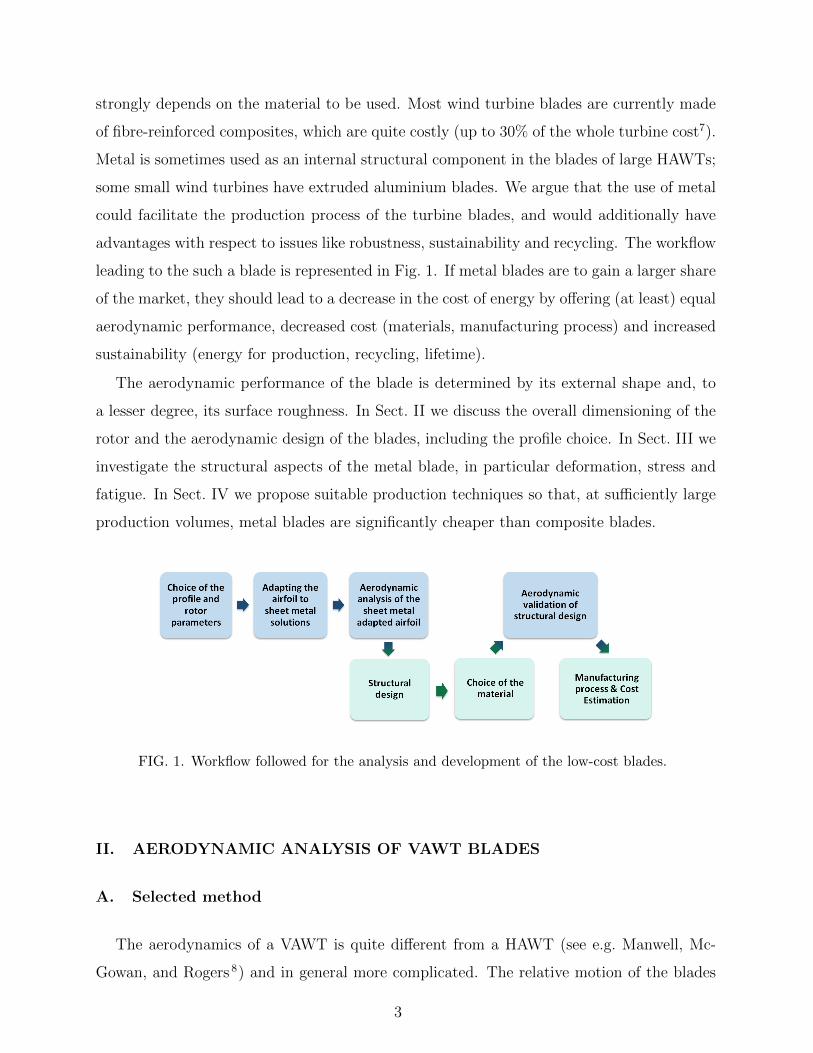
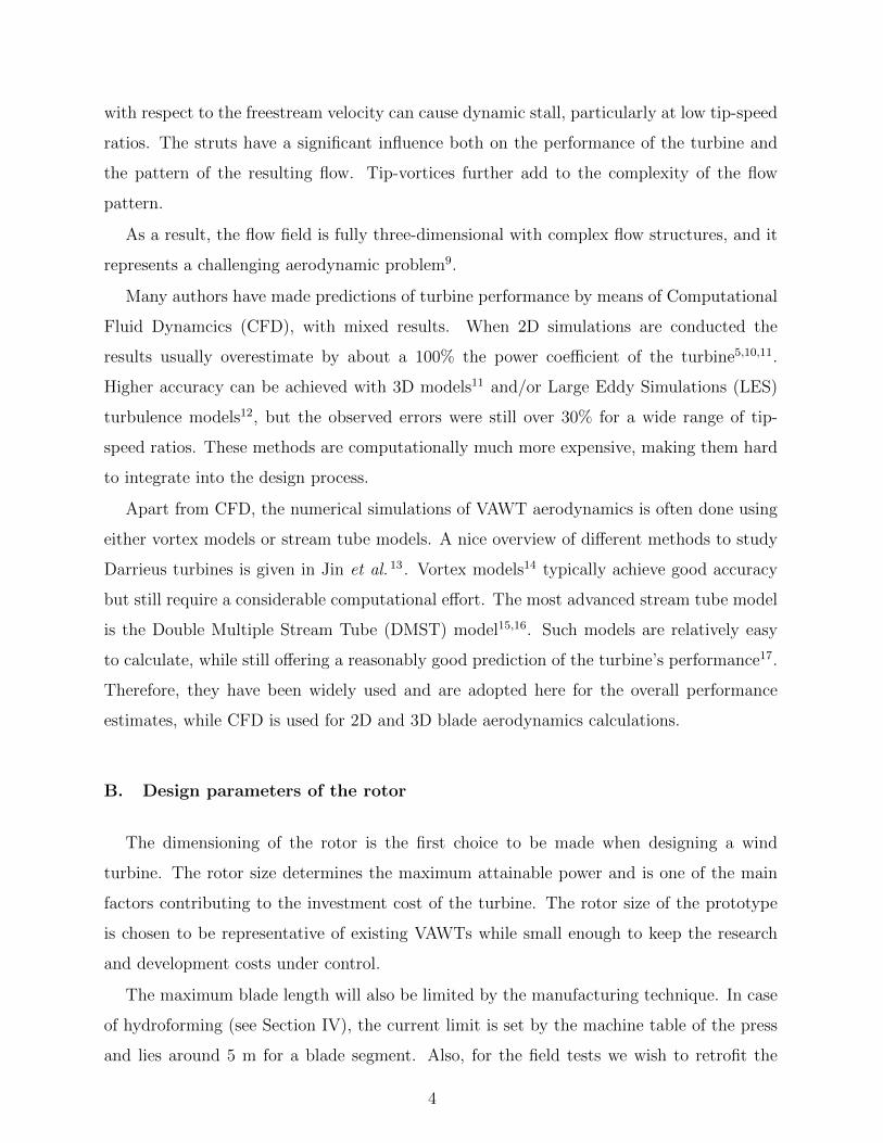
TABLE I. Main characteristics of a 1 kW demonstrator turbine.
Diameter 2.4 m
Blade length 3.0 m
Blade chord 180 mm
Max. angular speed 240 rpm
blades onto an existing turbine, which has a rotor diameter of 2.4 m and a length of 3 m,
with a 180 mm blade chord. The chord length and tip-speed ratio were chosen to optimise
the power coefficient. This of course depends on the profile of the adopted aerofoil (see
below). Together with the constraint on the centrifugal forces, the design tip-speed ratio
sets the maximum angular velocity. A DMST-simulation based on the S2027-aerofoil (see
below) and for a Reynolds number of 7×10⁵ predicts a maximum power coefficient of 0.48 at
a tip-speed ratio of 3.25. (Of course the true CP will be lower, as the presented values have
not been corrected for tip effects, drag of the struts, friction losses and generator efficiency.)
This leads to a wind turbine with an estimated rated power of 1 kW, with the dimensioning
summarised in Table I.
Tip-speed ratio (-)2 3 4 5
Po
we
r co
eff
icie
nt
(-)
0
0.1
0.2
0.3
0.4
0.5
FIG. 2. Power coefficient CP as a function of tip-speed ratio, calculated with a DMST model for
a Reynolds number of 7 × 10⁵.
A large number of profiles have been suggested for adoption in VAWT rotors, see e.g.
the classic SANDIA report18. It has also been suggested19 that mildly asymmetric profiles
5
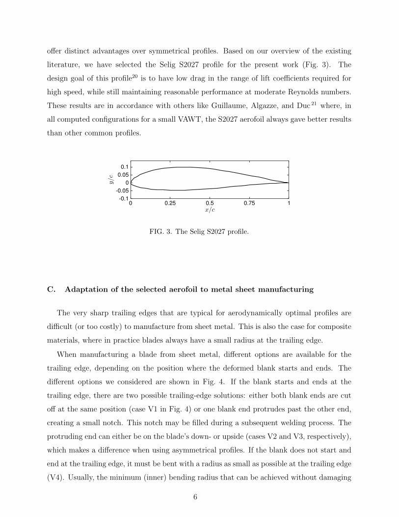
offer distinct advantages over symmetrical profiles. Based on our overview of the existing
literature, we have selected the Selig S2027 profile for the present work (Fig. 3). The
design goal of this profile20 is to have low drag in the range of lift coefficients required for
high speed, while still maintaining reasonable performance at moderate Reynolds numbers.
These results are in accordance with others like Guillaume, Algazze, and Duc 21 where, in
all computed configurations for a small VAWT, the S2027 aerofoil always gave better results
than other common profiles.
x/c0 0.25 0.5 0.75 1
y/c
-0.1
-0.05
0
0.05
0.1
FIG. 3. The Selig S2027 profile.
C. Adaptation of the selected aerofoil to metal sheet manufacturing
The very sharp trailing edges that are typical for aerodynamically optimal profiles are
difficult (or too costly) to manufacture from sheet metal. This is also the case for composite
materials, where in practice blades always have a small radius at the trailing edge.
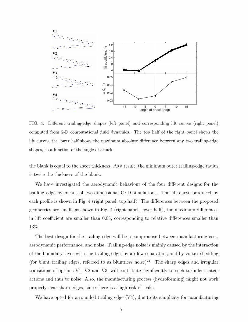
When manufacturing a blade from sheet metal, different options are available for the
trailing edge, depending on the position where the deformed blank starts and ends. The
different options we considered are shown in Fig. 4. If the blank starts and ends at the
trailing edge, there are two possible trailing-edge solutions: either both blank ends are cut
off at the same position (case V1 in Fig. 4) or one blank end protrudes past the other end,
creating a small notch. This notch may be filled during a subsequent welding process. The
protruding end can either be on the blade’s down- or upside (cases V2 and V3, respectively),
which makes a difference when using asymmetrical profiles. If the blank does not start and
end at the trailing edge, it must be bent with a radius as small as possible at the trailing edge
(V4). Usually, the minimum (inner) bending radius that can be achieved without damaging
6
V1
V2
V3
V4
angle of attack (deg)-15 -10 -5 0 5 10 15
lift
co
eff
icie
nt
(-)
-0.4
0
0.4
0.8
1.2
angle of attack (deg)-15 -10 -5 0 5 10 15
∆ C
L (
-)0.02
0.03
0.04
0.05
FIG. 4. Different trailing-edge shapes (left panel) and corresponding lift curves (right panel)
computed from 2-D computational fluid dynamics. The top half of the right panel shows the
lift curves, the lower half shows the maximum absolute difference between any two trailing-edge
shapes, as a function of the angle of attack.
the blank is equal to the sheet thickness. As a result, the minimum outer trailing-edge radius
is twice the thickness of the blank.
We have investigated the aerodynamic behaviour of the four different designs for the
trailing edge by means of two-dimensional CFD simulations. The lift curve produced by
each profile is shown in Fig. 4 (right panel, top half). The differences between the proposed
geometries are small: as shown in Fig. 4 (right panel, lower half), the maximum differences
in lift coefficient are smaller than 0.05, corresponding to relative differences smaller than
13%.
The best design for the trailing edge will be a compromise between manufacturing cost,
aerodynamic performance, and noise. Trailing-edge noise is mainly caused by the interaction
of the boundary layer with the trailing edge, by airflow separation, and by vortex shedding
(for blunt trailing edges, referred to as bluntness noise)22. The sharp edges and irregular
transitions of options V1, V2 and V3, will contribute significantly to such turbulent inter-
actions and thus to noise. Also, the manufacturing process (hydroforming) might not work
properly near sharp edges, since there is a high risk of leaks.
We have opted for a rounded trailing edge (V4), due to its simplicity for manufacturing
7
and the expected absence of turbulent noise. No further edge machining is required, and
there are no appreciable aerodynamic differences. Moreover, design V4 allows for an inner
reinforcement by folding in part of the sheet where the two edges meet and welding it
against the profile on both the intrados and the extrados. As the trailing-edge thickness is
comparable to the thickness of the boundary layer (between 6 mm at 5 m/s and 4.7 mm
at 25 m/s using flat-plate boundary layer theory23), a certain degree of tonal noise is to
be expected. However, when upscaling the prototype to larger chord lengths, the profile
becomes comparatively sharper (as the manufacturing constraints do not change) so that
the production of tonal noise is expected to decrease.
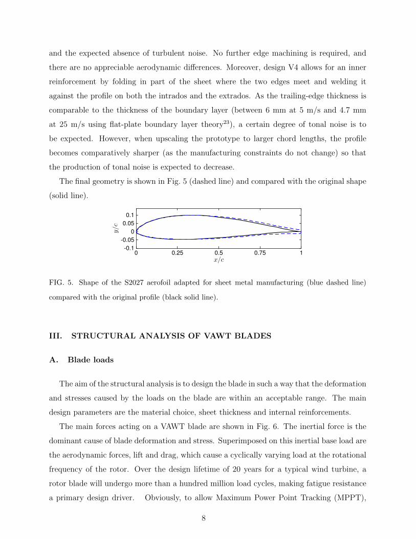
The final geometry is shown in Fig. 5 (dashed line) and compared with the original shape
(solid line).
x/c0 0.25 0.5 0.75 1
y/c
-0.1
-0.05
0
0.05
0.1
FIG. 5. Shape of the S2027 aerofoil adapted for sheet metal manufacturing (blue dashed line)
compared with the original profile (black solid line).
III. STRUCTURAL ANALYSIS OF VAWT BLADES
A. Blade loads
The aim of the structural analysis is to design the blade in such a way that the deformation
and stresses caused by the loads on the blade are within an acceptable range. The main
design parameters are the material choice, sheet thickness and internal reinforcements.
The main forces acting on a VAWT blade are shown in Fig. 6. The inertial force is the
dominant cause of blade deformation and stress. Superimposed on this inertial base load are
the aerodynamic forces, lift and drag, which cause a cyclically varying load at the rotational
frequency of the rotor. Over the design lifetime of 20 years for a typical wind turbine, a
rotor blade will undergo more than a hundred million load cycles, making fatigue resistance
a primary design driver. Obviously, to allow Maximum Power Point Tracking (MPPT),
8
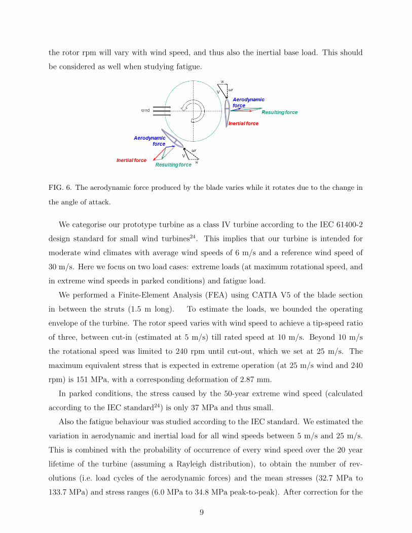
the rotor rpm will vary with wind speed, and thus also the inertial base load. This should
be considered as well when studying fatigue.
FIG. 6. The aerodynamic force produced by the blade varies while it rotates due to the change in
the angle of attack.
We categorise our prototype turbine as a class IV turbine according to the IEC 61400-2
design standard for small wind turbines24. This implies that our turbine is intended for
moderate wind climates with average wind speeds of 6 m/s and a reference wind speed of
30 m/s. Here we focus on two load cases: extreme loads (at maximum rotational speed, and
in extreme wind speeds in parked conditions) and fatigue load.
We performed a Finite-Element Analysis (FEA) using CATIA V5 of the blade section
in between the struts (1.5 m long). To estimate the loads, we bounded the operating
envelope of the turbine. The rotor speed varies with wind speed to achieve a tip-speed ratio
of three, between cut-in (estimated at 5 m/s) till rated speed at 10 m/s. Beyond 10 m/s
the rotational speed was limited to 240 rpm until cut-out, which we set at 25 m/s. The
maximum equivalent stress that is expected in extreme operation (at 25 m/s wind and 240
rpm) is 151 MPa, with a corresponding deformation of 2.87 mm.
In parked conditions, the stress caused by the 50-year extreme wind speed (calculated
according to the IEC standard24) is only 37 MPa and thus small.
Also the fatigue behaviour was studied according to the IEC standard. We estimated the
variation in aerodynamic and inertial load for all wind speeds between 5 m/s and 25 m/s.
This is combined with the probability of occurrence of every wind speed over the 20 year
lifetime of the turbine (assuming a Rayleigh distribution), to obtain the number of rev-
olutions (i.e. load cycles of the aerodynamic forces) and the mean stresses (32.7 MPa to
133.7 MPa) and stress ranges (6.0 MPa to 34.8 MPa peak-to-peak). After correction for the
9
mean stress through the Goodman approximation, which is a conservative estimate25, and
given the material properties as described in Section III C, we found that the Miner’s rule
accumulated damage24 was only 0.08, and thus well below 1.
Assessing the impact of the fluctuating inertial loads due to variations in rotor rpm is more
subtle. One needs to know the time scales of wind speed variations, the rotor inertia and the
time constant of the MPPT control architecture. However, we can safely neglect small wind-
speed variations (with small stress fluctuations) on the same ground as the above-studied
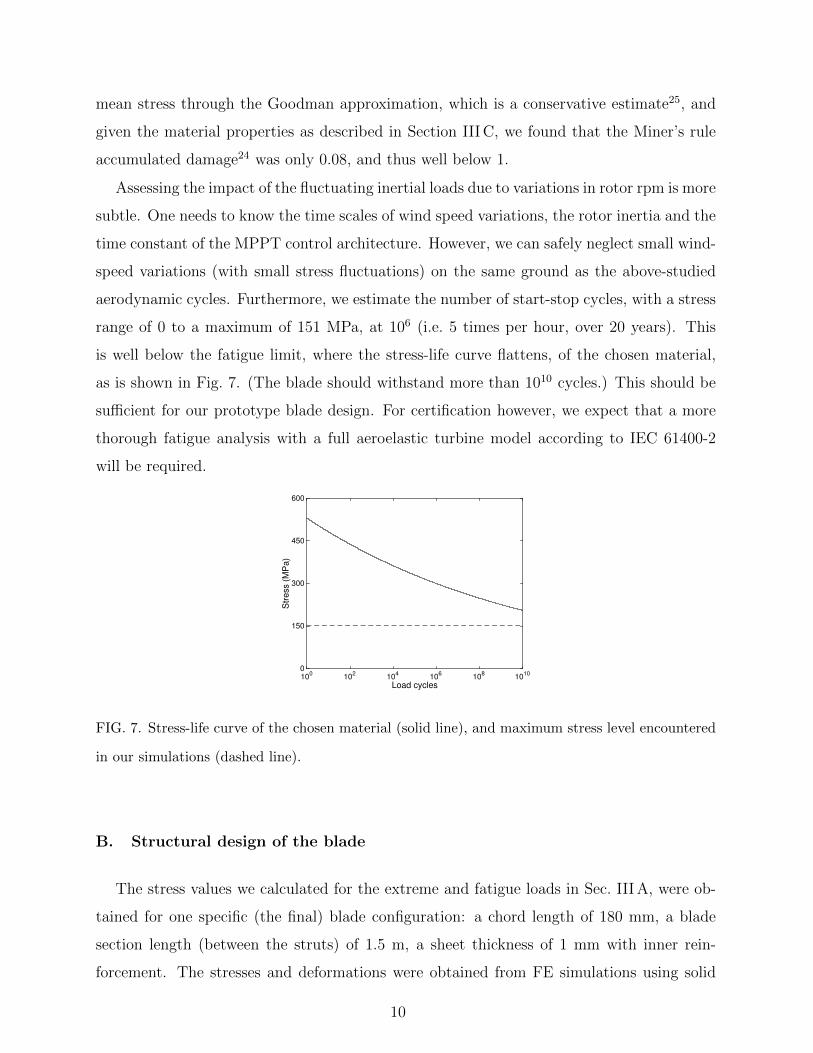
aerodynamic cycles. Furthermore, we estimate the number of start-stop cycles, with a stress
range of 0 to a maximum of 151 MPa, at 106 (i.e. 5 times per hour, over 20 years). This
is well below the fatigue limit, where the stress-life curve flattens, of the chosen material,
as is shown in Fig. 7. (The blade should withstand more than 1010 cycles.) This should be
sufficient for our prototype blade design. For certification however, we expect that a more
thorough fatigue analysis with a full aeroelastic turbine model according to IEC 61400-2
will be required.
Load cycles10
010
210
410
610
810
10
Str
ess (
MP
a)
0
150
300
450
600
FIG. 7. Stress-life curve of the chosen material (solid line), and maximum stress level encountered
in our simulations (dashed line).
B. Structural design of the blade
The stress values we calculated for the extreme and fatigue loads in Sec. III A, were ob-
tained for one specific (the final) blade configuration: a chord length of 180 mm, a blade
section length (between the struts) of 1.5 m, a sheet thickness of 1 mm with inner rein-
forcement. The stresses and deformations were obtained from FE simulations using solid
10
elements. It is important to realise that these stress and deformation levels depend critically
on the blade configuration, as we will illustrate now. We simulate different configurations
for rated conditions (10 m/s wind speed, 240 rpm), where the load is just shy of 90% of
the maximum load. To test a multitude of different configuration, we used shell elements
to speed up the FE computations. The precise values of deformation and stress will differ
slightly from those of Sec. III A.
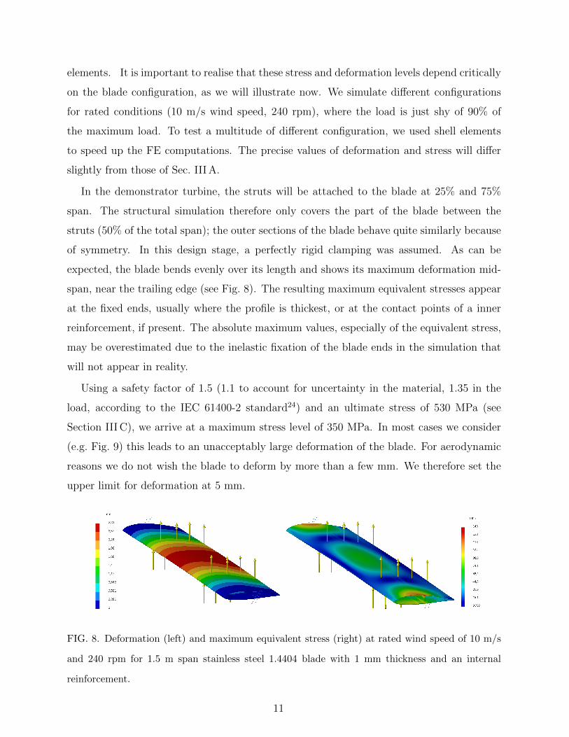
In the demonstrator turbine, the struts will be attached to the blade at 25% and 75%
span. The structural simulation therefore only covers the part of the blade between the
struts (50% of the total span); the outer sections of the blade behave quite similarly because
of symmetry. In this design stage, a perfectly rigid clamping was assumed. As can be
expected, the blade bends evenly over its length and shows its maximum deformation mid-
span, near the trailing edge (see Fig. 8). The resulting maximum equivalent stresses appear
at the fixed ends, usually where the profile is thickest, or at the contact points of a inner
reinforcement, if present. The absolute maximum values, especially of the equivalent stress,
may be overestimated due to the inelastic fixation of the blade ends in the simulation that
will not appear in reality.
Using a safety factor of 1.5 (1.1 to account for uncertainty in the material, 1.35 in the
load, according to the IEC 61400-2 standard24) and an ultimate stress of 530 MPa (see
Section III C), we arrive at a maximum stress level of 350 MPa. In most cases we consider
(e.g. Fig. 9) this leads to an unacceptably large deformation of the blade. For aerodynamic
reasons we do not wish the blade to deform by more than a few mm. We therefore set the
upper limit for deformation at 5 mm.
FIG. 8. Deformation (left) and maximum equivalent stress (right) at rated wind speed of 10 m/s
and 240 rpm for 1.5 m span stainless steel 1.4404 blade with 1 mm thickness and an internal
reinforcement.
11
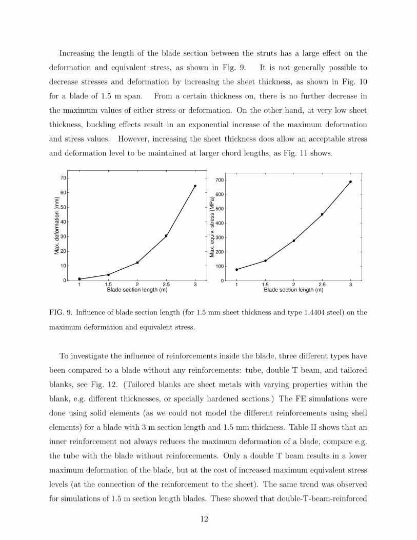
Increasing the length of the blade section between the struts has a large effect on the
deformation and equivalent stress, as shown in Fig. 9. It is not generally possible to
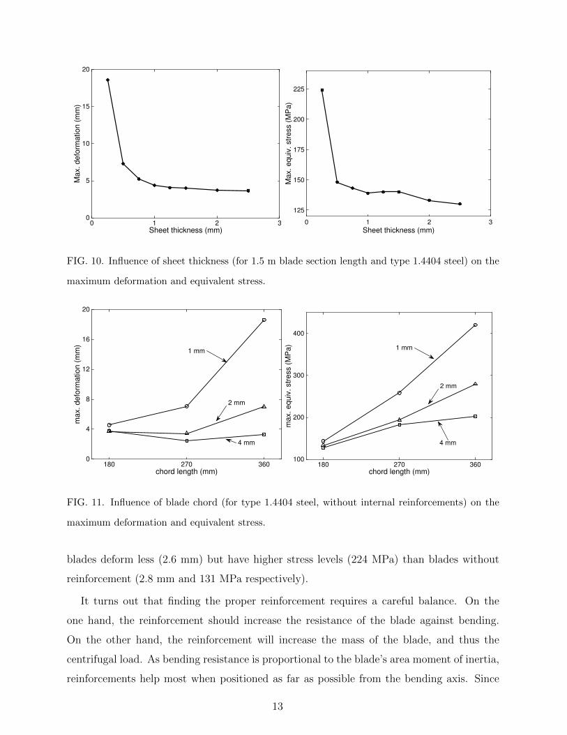
decrease stresses and deformation by increasing the sheet thickness, as shown in Fig. 10
for a blade of 1.5 m span. From a certain thickness on, there is no further decrease in
the maximum values of either stress or deformation. On the other hand, at very low sheet
thickness, buckling effects result in an exponential increase of the maximum deformation
and stress values. However, increasing the sheet thickness does allow an acceptable stress
and deformation level to be maintained at larger chord lengths, as Fig. 11 shows.
Blade section length (m)1 1.5 2 2.5 3
Ma
x.
de
form
atio
n (
mm
)
0
10
20
30
40
50
60
70
Blade section length (m)1 1.5 2 2.5 3
Max. equiv
. str
ess (
MP
a)
0
100
200
300
400
500
600
700
FIG. 9. Influence of blade section length (for 1.5 mm sheet thickness and type 1.4404 steel) on the
maximum deformation and equivalent stress.
To investigate the influence of reinforcements inside the blade, three different types have
been compared to a blade without any reinforcements: tube, double T beam, and tailored
blanks, see Fig. 12. (Tailored blanks are sheet metals with varying properties within the
blank, e.g. different thicknesses, or specially hardened sections.) The FE simulations were
done using solid elements (as we could not model the different reinforcements using shell
elements) for a blade with 3 m section length and 1.5 mm thickness. Table II shows that an
inner reinforcement not always reduces the maximum deformation of a blade, compare e.g.
the tube with the blade without reinforcements. Only a double T beam results in a lower
maximum deformation of the blade, but at the cost of increased maximum equivalent stress
levels (at the connection of the reinforcement to the sheet). The same trend was observed
for simulations of 1.5 m section length blades. These showed that double-T-beam-reinforced
12
Sheet thickness (mm)0 1 2 3
Ma
x.
de
form
atio
n (
mm
)
0
5
10
15
20
Sheet thickness (mm)0 1 2 3
Max. equiv
. str
ess (
MP
a)
125
150
175
200
225
FIG. 10. Influence of sheet thickness (for 1.5 m blade section length and type 1.4404 steel) on the
maximum deformation and equivalent stress.
chord length (mm)180 270 360
ma
x.
de
form
atio
n (
mm
)
0
4
8
12
16
20
1 mm
2 mm
4 mm
chord length (mm)180 270 360
max. equiv
. str
ess (
MP
a)
100
200
300
400
1 mm
2 mm
4 mm
FIG. 11. Influence of blade chord (for type 1.4404 steel, without internal reinforcements) on the
maximum deformation and equivalent stress.
blades deform less (2.6 mm) but have higher stress levels (224 MPa) than blades without
reinforcement (2.8 mm and 131 MPa respectively).
It turns out that finding the proper reinforcement requires a careful balance. On the
one hand, the reinforcement should increase the resistance of the blade against bending.
On the other hand, the reinforcement will increase the mass of the blade, and thus the
centrifugal load. As bending resistance is proportional to the blade’s area moment of inertia,
reinforcements help most when positioned as far as possible from the bending axis. Since
13
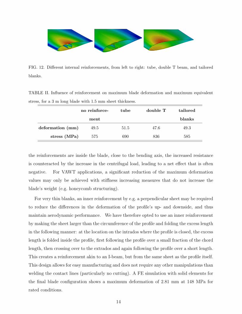
FIG. 12. Different internal reinforcements, from left to right: tube, double T beam, and tailored
blanks.
TABLE II. Influence of reinforcement on maximum blade deformation and maximum equivalent
stress, for a 3 m long blade with 1.5 mm sheet thickness.
no reinforce-
ment
tube double T tailored
blanks
deformation (mm) 49.5 51.5 47.6 49.3
stress (MPa) 575 690 836 585
the reinforcements are inside the blade, close to the bending axis, the increased resistance
is counteracted by the increase in the centrifugal load, leading to a net effect that is often
negative. For VAWT applications, a significant reduction of the maximum deformation
values may only be achieved with stiffness increasing measures that do not increase the
blade’s weight (e.g. honeycomb structuring).
For very thin blanks, an inner reinforcement by e.g. a perpendicular sheet may be required
to reduce the differences in the deformation of the profile’s up- and downside, and thus
maintain aerodynamic performance. We have therefore opted to use an inner reinforcement
by making the sheet larger than the circumference of the profile and folding the excess length
in the following manner: at the location on the intrados where the profile is closed, the excess
length is folded inside the profile, first following the profile over a small fraction of the chord
length, then crossing over to the extrados and again following the profile over a short length.
This creates a reinforcement akin to an I-beam, but from the same sheet as the profile itself.
This design allows for easy manufacturing and does not require any other manipulations than
welding the contact lines (particularly no cutting). A FE simulation with solid elements for
the final blade configuration shows a maximum deformation of 2.81 mm at 148 MPa for
rated conditions.
14
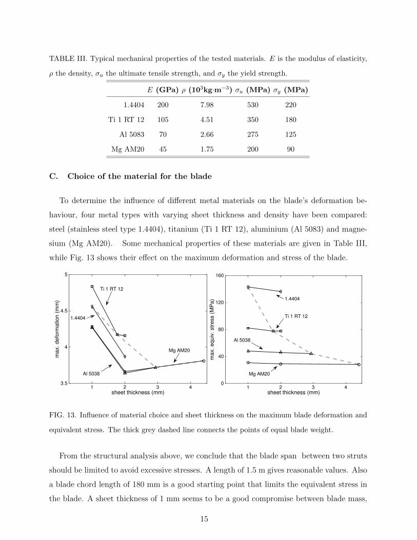
TABLE III. Typical mechanical properties of the tested materials. E is the modulus of elasticity,
ρ the density, σu the ultimate tensile strength, and σy the yield strength.
E (GPa) ρ (103kg·m−3) σu (MPa) σy (MPa)
1.4404 200 7.98 530 220
Ti 1 RT 12 105 4.51 350 180
Al 5083 70 2.66 275 125
Mg AM20 45 1.75 200 90
C. Choice of the material for the blade
To determine the influence of different metal materials on the blade’s deformation be-
haviour, four metal types with varying sheet thickness and density have been compared:
steel (stainless steel type 1.4404), titanium (Ti 1 RT 12), aluminium (Al 5083) and magne-
sium (Mg AM20). Some mechanical properties of these materials are given in Table III,
while Fig. 13 shows their effect on the maximum deformation and stress of the blade.
sheet thickness (mm)1 2 3 4
max. defo
rmation (
mm
)
3.5
4
4.5
5
Mg AM20
Al 5038
Ti 1 RT 12
1.4404
sheet thickness (mm)1 2 3 4
max. equiv
. str
ess (
MP
a)
0
40
80
120
160
1.4404
Ti 1 RT 12
Al 5038
Mg AM20
FIG. 13. Influence of material choice and sheet thickness on the maximum blade deformation and
equivalent stress. The thick grey dashed line connects the points of equal blade weight.
From the structural analysis above, we conclude that the blade span between two struts
should be limited to avoid excessive stresses. A length of 1.5 m gives reasonable values. Also
a blade chord length of 180 mm is a good starting point that limits the equivalent stress in
the blade. A sheet thickness of 1 mm seems to be a good compromise between blade mass,
15
deformation and equivalent stress. An inner reinforcement helps maintain an aerodynamic
shape of the profile. Stresses and deformation can be brought down by using Mg AM20
rather than steel type 1.4404 (albeit with a lesser material strength). The possibility of
using magnesium will be considered in the future, especially as Mg AM20 sheet metal is
expected to become cheaper.
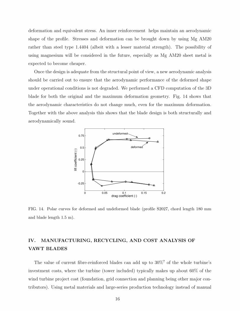
Once the design is adequate from the structural point of view, a new aerodynamic analysis
should be carried out to ensure that the aerodynamic performance of the deformed shape
under operational conditions is not degraded. We performed a CFD computation of the 3D
blade for both the original and the maximum deformation geometry. Fig. 14 shows that
the aerodynamic characteristics do not change much, even for the maximum deformation.
Together with the above analysis this shows that the blade design is both structurally and
aerodynamically sound.
drag coefficient (-)0 0.05 0.1 0.15 0.2
lift
co
eff
icie
nt
(-)
-0.25
0
0.25
0.5
0.75undeformed
deformed
FIG. 14. Polar curves for deformed and undeformed blade (profile S2027, chord length 180 mm
and blade length 1.5 m).
IV. MANUFACTURING, RECYCLING, AND COST ANALYSIS OF
VAWT BLADES
The value of current fibre-reinforced blades can add up to 30%7 of the whole turbine’s
investment costs, where the turbine (tower included) typically makes up about 60% of the
wind turbine project cost (foundation, grid connection and planning being other major con-
tributors). Using metal materials and large-series production technology instead of manual
16

TABLE IV. Comparison of metal forming processes. We used CNC bending, roll forming, and
hydroforming for the manufacturing of the blade.
CNC
bending
swing
folding
roll
rounding
roll
forming
profile
bending
extrusion hydro-
forming
eligibility for low quantities + + + – + + +
eligibility for high quanti-
ties
– 0 – ++ – + +
variability (sizes) + + + – – – –
investment cost + + + – + – –
state of the art process ++ ++ + ++ + ++ +
repeating accuracy + + + + – ++ ++
future potential (complex
profiles)
– 0 – ++ / + ++
processes of composites, offers a potentially large cost reduction. Moreover, metal blades
are easier to recycle, reducing the total life-cycle impact of turbine blades.
Apart from the differences in material and manufacturing costs between metal and com-
posite blades that will be described below, also recycling issues distinguish these materials.
A full Life-Cycle Assessment (LCA) of metal blades and composite blades is beyond the
scope of this paper. Yet some general conclusions can be drawn from the vast number of
LCAs of entire turbines available in the literature, see e.g. Haapala and Prempreeda 26 for
a specific comparison of two turbines with composite blades and a steel tower, or Dolan
and Heath 27 for a summary of multiple LCA studies. Both steel and composites have the
greatest (negative) impact at the level of raw material extraction and production. With
respect to end-of-life treatment however, steel can be successfully recycled (losses of 10%
are common) while composites are typically only used for landfill. Without more mature
recycling techniques for composites, steel is advantageous from a cradle-to-grave perspective.
A. Choice of the manufacturing technology
Several metal forming methods were compared using criteria like eligibility for low and
high quantities, size variability, repeating accuracy, invest and process cost as well as their
potential for more complex rotor designs (Table IV).
When comparing such manufacturing processes, one has to consider four main factors
that affect the production cost:
17
• General production parameters (e.g. quantity, lot sizes, production rates, makespan
or production life cycle, depreciation time, interest rates),
• Investment costs such as machines, tooling, research and development (R&D), han-
dling equipment,
• Material costs (depending on the specific alloy and the usage of semi-finished products,
process specific rate of material use),
• Process costs (e.g. machine and man-hour rates for the manufacturing process).
Usually, the necessary equipment and machines for the production of blades is already
available at contract manufacturers. Therefore the investment cost is often the part-specific
tooling and the development and engineering of a production process. Depending on the
number of parts that will be produced over the makespan of the part, their contribution to
a part’s production cost varies widely.
The focus in this paper is on straight H-type VAWT blades with constant cross section,
as a first step. Such blades are currently made as extruded aluminium parts or from fibre-
reinforced composite materials. For such easy-to-manufacture blades, certainly in small to
medium quantities, manufacturing processes should be based on flexible tooling technology
without part-specific milled dies. Therefore we have chosen bending by Computer Numerical
Control (CNC) as the optimal manufacturing process for the preform of the blade prototypes.
In the long run, we work towards large-series production technologies that can be extended
towards more complex rotor designs (curved blade axes, varying cross sections, surface
structuring). Therefore, we have opted for a combination of roll forming and hydroforming
for the series production technology.
Hydroforming always requires some type of preform, usually a straight or bent closed
profile or tube, that is then formed with a high pressure (HP) medium (mainly liquid or gas,
depending on the forming temperature) from the inside to the outside in a die of the final
geometry. Processes that are technically suitable to produce such preforms for our case are
CNC bending (resulting in an edgy preform profile) and roll forming (round profile).
The hydroforming process is controled by several parameters: the HP fluid’s inner pres-
sure for forming the part (this depends on the material strength and thickness), the press
closing force to keep the press closed (against the internal pressure), and the axial sealing
18
force to prevent leakage at the part’s ends. The hydroforming process itself contains four
main steps:
• placing the preform in the opened press, and closing the press,
• pushing sealing stamps slightly into the profile ends, and filling the part with fluid
while evacuating the remaining air,
• building up the press closing and the axial sealing forces while increasing the pressure
of the fluid; this is the actual forming step,
• gradually releasing the internal pressure and the forces, opening the press and removing
the formed part.
Due to the forming operations, stresses are induced in the material that can remain
after the forming. The highest forming stresses for our design occur at the trailing edge,
given the small curvature of the profile there. These stresses are not expected to cause
durability issues, as the trailing edge is not very stressed. The load-bearing parts of the
blade are much less curved and thus less prone to residual stresses. Yet, should future
findings indicate that durability is affected, one could always envisage a post-forming heat
treatment step to alleviate the stresses.
B. Cost benefits of metal blades
A large benefit of using metal materials is their low price per kilogram compared to
fibre-reinforced materials. While Glass-Fibre-Reinforced Plastic (GFRP) can reach a cost
of 7-8 e/kg (and Carbon-Fibre-Reinforced Plastics even 30-50 e/kg), steel alloys are well
below that value7. Stainless steel sheet metals that may be considered for the prototype
turbine usually cost between 4 e/kg and 5 e/kg and large series car-industry steels like
DP600 are just under ∼ 1 e/kg but have to be treated against corrosion. Our 3 m long
blade prototype (with sheet thickness of 1 mm) will weigh around 10 kg, resulting in a
material cost of 40-50 e. This is about the same cost as for a GFRP blade, since such a
blade would only weigh around 5-6 kg. CFRP would be substantially lighter but much more
expensive (at around 200 e).
19
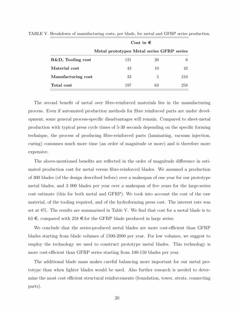
TABLE V. Breakdown of manufacturing costs, per blade, for metal and GFRP series production.
Cost in e
Metal prototypes Metal series GFRP series
R&D, Tooling cost 121 20 6
Material cost 43 10 42
Manufacturing cost 33 5 210
Total cost 197 63 258
The second benefit of metal over fibre-reinforced materials lies in the manufacturing
process. Even if automated production methods for fibre reinforced parts are under devel-
opment, some general process-specific disadvantages will remain. Compared to sheet-metal
production with typical press cycle times of 5-30 seconds depending on the specific forming
technique, the process of producing fibre-reinforced parts (laminating, vacuum injection,
curing) consumes much more time (an order of magnitude or more) and is therefore more
expensive.
The above-mentioned benefits are reflected in the order of magnitude difference in esti-
mated production cost for metal versus fibre-reinforced blades. We assumed a production
of 300 blades (of the design described before) over a makespan of one year for our prototype
metal blades, and 3 000 blades per year over a makespan of five years for the large-series
cost estimate (this for both metal and GFRP). We took into account the cost of the raw
material, of the tooling required, and of the hydroforming press cost. The interest rate was
set at 8%. The results are summarised in Table V. We find that cost for a metal blade is to
63 e, compared with 258 e for the GFRP blade produced in large series.
We conclude that the series-produced metal blades are more cost-efficient than GFRP
blades starting from blade volumes of 1500-2000 per year. For low volumes, we suggest to
employ the technology we used to construct prototype metal blades. This technology is
more cost-efficient than GFRP series starting from 100-150 blades per year.
The additional blade mass makes careful balancing more important for our metal pro-
totype than when lighter blades would be used. Also further research is needed to deter-
mine the most cost efficient structural reinforcements (foundation, tower, struts, connecting
parts).
20

V. CONCLUSIONS
In this paper we show that it is possible to build metal blades for small and medium-
sized wind turbines that are competitive with fibre-reinforced composite blades. The main
parameters influencing the blade’s aerodynamic performance (operational parameters of the
turbine, profile geometry) have been identified and evaluated taking into account structural
effects (sheet thickness, inner reinforcements, materials, fatigue behaviour). The result is
a first demonstrator blade and a basis for future potential through large-series production
(e.g. for the use of magnesium, when its availability and level of examination increases and
price decreases in the coming years).
The demonstrator blade (see Fig. 15) is 3 m in length (with 1.5 m bending length, which
is the distance between the two struts) at a chord of 180 mm, made of stainless steel in 1.0
mm sheet thickness and with a perpendicular sheet as inner reinforcement. This blade has
a moderate deformation and a tolerable stress level combined with a minimum amount of
material and associated manufacturing costs.
FIG. 15. Prototype rotor prepared for the field tests.
Through the use of mass production technology and performance optimization in a farm
of counter-rotating turbines, it is possible to achieve as good a turbine performance as
can be achieved with traditional composite blades while improving overall profitability and
21
sustainability.
VI. ACKNOWLEDGEMENTS
This work was performed in the context of the EFB-lead HyBlade project in the COR-
NET framework. The support of the German AIF association and the Belgian “Agency for
Innovation by Science and Technology in Flanders (IWT)” is gratefully acknowledged.
REFERENCES
1M. M. Aslam Bhutta, N. Hayat, A. U. Farooq, Z. Ali, S. R. Jamil, and Z. Hussain,
Renewable and Sustainable Energy Reviews 16, 1926 (2012).
2K. Duraisamy and V. Lakshminarayan, in Proceedings of the 32nd AIAA Applied Aerody-
namics Conference (AIAA, Atlanta, GA, 2014) pp. 1–17.
3J. O. Dabiri, Journal of renewable and sustainable energy 3 (2011).
4W. T. Chong, A. Fazlizan, S. C. Poh, K. C. Pan, W. P. Hew, and F. B. Hsiao, Applied
Energy 112, 601 (2013).
5R. Nobile, M. Vahdati, J. F. Barlow, and A. Mewburn-Crook, Journal of Wind Engineering
and Industrial Aerodynamics 125, 168 (2014).
6K. Pope, T. Dincer, and G. F. Naterer, Renewable Energy 35, 2102 (2010).
7E. Hau, Wind Turbines - Fundamentals, Technologies, Application (Springer-Verlag,
Berlin, 2013).
8F. Manwell, J. McGowan, and A. Rogers, Wind Energy Explained, 2nd ed. (John Wiley
& Sons, Chichester, 2009).
9M. Nini, V. Motta, G. Bindolino, and A. Guardone, Three-dimensional simulation of a
complete Vertical Axis Wind Turbine using overlapping grids (Journal of Computational
and Applied Mathematics, in Press, 2014).
10M. R. Castelli, A. Englaro, and E. Benini, Energy 36, 4919 (2011).
11R. Howell, N. Qin, J. Edwards, and N. Durrani, Renewable Energy 35, 412 (2010).
12C. Li, S. Zhu, Y. l. Xu, and Y. Xiao, Renewable Energy 51, 317 (2013).
13X. Jin, G. Zhao, K. Gao, and W. Ju, Renewable and Sustainable Energy Reviews 42, 212
(2015).
22
14J. H. Strickland, B. Webster, and T. Nguyen, Journal of Fluids Engineering 101, 500
(1979).
15I. Paraschivoiu and F. Delclaux, Journal of energy 7, 250 (1983).
16I. Paraschivoiu, Journal of energy 7, 610 (1983).
17M. Islam, D. S.-K. Ting, and A. Fartaj, Renewable and Sustainable Energy Reviews 12,
1087 (2008).
18R. E. Sheldahl and P. C. Klimas, “Aerodynamic characteristics of seven symmetrical airfoil
sections through 180-degree angle of attack for use in aerodynamic analysis of vertical axis
wind turbines.” Tech. Rep. SAND81-2114 (Sandia National Laboratories, 1981).
19M. H. Mohamed, Performance investigation of H-rotor Darrieus turbine with new airfoil
shapes (Energy (47), 2012) pp. 522–530.
20M. S. Selig, in Proceedings of the AIAA 23rd Aerospace Sciences Meeting (American In-
stitute of Aeronautics and Astronautics, Reno, 1985).
21C. Guillaume, S. Algazze, and E. Duc, Economic feasibility of wind turbines for individual
households (EWEA, Marseille, 2009).
22M. F. Barone, “Survey of techniques for reduction of wind turbine blade trailing edge
noise,” Tech. Rep. SAND2011-5252 (Sandia National Laboratories, 2011).
23Y. A. Cengel and J. M. Cimbala, Essentials of fluid mechanics: fundamentals and appli-
cations (McGraw-Hill Higher Education, 2006).
24International Electrotechnical Commission, 61400-2:2013: Design requirements for small
wind turbines, IEC (2013).
25N. E. Dowling, “Mean stress effects in stress-life and strain-life fatigue,” Tech. Rep. SAE
Technical Paper 2004-01-2227 (Society of Autmotive Engineers, 2004).
26K. R. Haapala and P. Prempreeda, International Journal of Sustainable Manufacturing 3,
170 (2014).
27S. L. Dolan and G. A. Heath, Journal of Industrial Ecology 16, S136 (2012).
23