Embed Size (px)
Citation preview

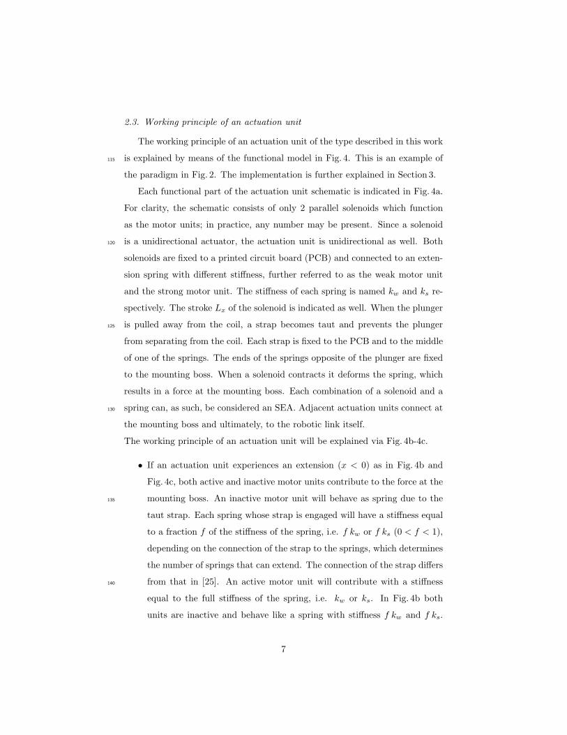
Vrije Universiteit Brussel
A muscle-like recruitment actuator with modular redundant actuation units for soft roboticsMathijssen, Glenn; Schultz, Joshua; Vanderborght, Bram; Bicchi, Antonio
Published in:Robotics and Autonomous Systems
DOI:10.1016/j.robot.2015.06.010
Publication date:2015
License:Unspecified
Document Version:Accepted author manuscript
Link to publication
Citation for published version (APA):Mathijssen, G., Schultz, J., Vanderborght, B., & Bicchi, A. (2015). A muscle-like recruitment actuator withmodular redundant actuation units for soft robotics. Robotics and Autonomous Systems, 74(Part A), 40-50.https://doi.org/10.1016/j.robot.2015.06.010
General rightsCopyright and moral rights for the publications made accessible in the public portal are retained by the authors and/or other copyright ownersand it is a condition of accessing publications that users recognise and abide by the legal requirements associated with these rights.
• Users may download and print one copy of any publication from the public portal for the purpose of private study or research. • You may not further distribute the material or use it for any profit-making activity or commercial gain • You may freely distribute the URL identifying the publication in the public portalTake down policyIf you believe that this document breaches copyright please contact us providing details, and we will remove access to the work immediatelyand investigate your claim.
Download date: 01. Dec. 2021
A muscle-like recruitment actuator with
modular redundant actuation units for soft robotics
Glenn Mathijssena,d,, Joshua Schultzb,c,Bram Vanderborghta, Antonio Bicchib,d
aDepartment of Mechanical Engineering, Vrije Universiteit Brussel (VUB), B-1050Brussels, Belgium
bDepartment of Advanced Robotics, Istituto Italiano di Tecnologia (IIT), 16163 Genova,GE, Italy
cDepartment of Mechanical Engineering, the University of Tulsa, Tulsa, OK 74104, USAdBioengineering and Robotics Research Center, Centro E. Piaggio, Universit di Pisa, 56112
Pisa, PI, Italy
Abstract
Human muscles contrast sharply with traditional robot actuators in that they
consist of several motor units, connected in series and parallel, which can be
progressively recruited, or brought into the active state. Some roboticists have
explored this idea in robotic actuators, striving for improvements such as the
ability to withstand partial damage, inexpensive repeatability by discrete open
loop control, the potential of modular actuators, etc. The down side of this is
that these systems become rather complex or rely on less widely used actuation
techniques such as piezo-actuators or SMAs to produce a compact implementa-
tion. In this paper, we present a novel design of a modular redundant actuation
unit which can be combined in various combinations to form compliant actuators
with varying characteristics. The actuation unit consists of discretely activated
solenoids with an integrated compliant coupling. This paper presents the work-
ing principle and discusses the physical implementation in detail. Failure of a
single motor unit will merely lead to a loss in performance rather than failure
of the actuator. Since each motor unit is discrete, neither power electronics
nor control require analog signals. Isometric experiments display the actuation
∗Corresponding authorEmail address: [email protected] (Glenn Mathijssen)
Preprint submitted to Robotics and Autonomous Systems October 22, 2014
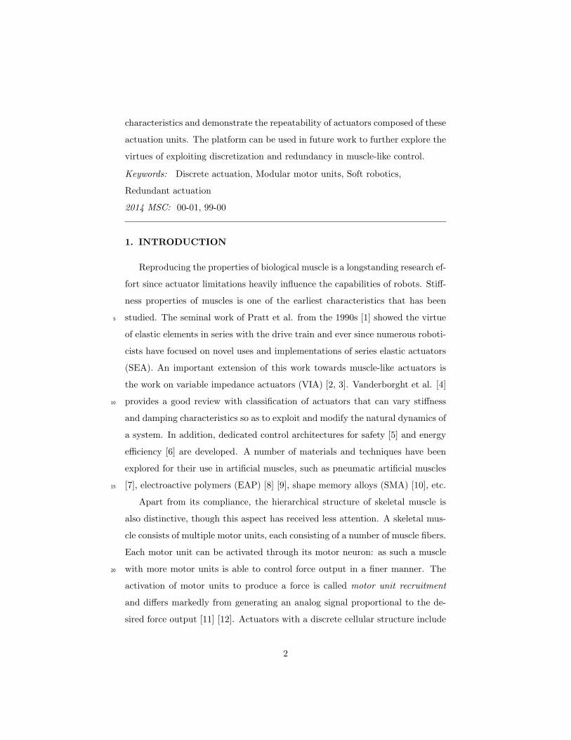
characteristics and demonstrate the repeatability of actuators composed of these
actuation units. The platform can be used in future work to further explore the
virtues of exploiting discretization and redundancy in muscle-like control.
Keywords: Discrete actuation, Modular motor units, Soft robotics,
Redundant actuation
2014 MSC: 00-01, 99-00
1. INTRODUCTION
Reproducing the properties of biological muscle is a longstanding research ef-
fort since actuator limitations heavily influence the capabilities of robots. Stiff-
ness properties of muscles is one of the earliest characteristics that has been
studied. The seminal work of Pratt et al. from the 1990s [1] showed the virtue5
of elastic elements in series with the drive train and ever since numerous roboti-
cists have focused on novel uses and implementations of series elastic actuators
(SEA). An important extension of this work towards muscle-like actuators is
the work on variable impedance actuators (VIA) [2, 3]. Vanderborght et al. [4]
provides a good review with classification of actuators that can vary stiffness10
and damping characteristics so as to exploit and modify the natural dynamics of
a system. In addition, dedicated control architectures for safety [5] and energy
efficiency [6] are developed. A number of materials and techniques have been
explored for their use in artificial muscles, such as pneumatic artificial muscles
[7], electroactive polymers (EAP) [8] [9], shape memory alloys (SMA) [10], etc.15
Apart from its compliance, the hierarchical structure of skeletal muscle is
also distinctive, though this aspect has received less attention. A skeletal mus-
cle consists of multiple motor units, each consisting of a number of muscle fibers.
Each motor unit can be activated through its motor neuron: as such a muscle
with more motor units is able to control force output in a finer manner. The20
activation of motor units to produce a force is called motor unit recruitment
and differs markedly from generating an analog signal proportional to the de-
sired force output [11] [12]. Actuators with a discrete cellular structure include
2
the work of Dittrich [13], MacNair [14] and Huston et al. [15]. Both of these
works present a type of actuator that is made up of numerous sub-actuators.25
This redundancy increases the robustness of these actuators. Failure of an elec-
tromechanical component will only lead to a loss in performance instead of a
loss of a complete degree of freedom (DOF), since the remaining undamaged
units can continue to perform the task.The cellular structure opens the possi-
bility for modularity in the actuators which represents an untried frontier in30
engineering. In Mathijssen et al. [16] the series-parallel elastic actuation con-
cept was proposed whereby multiple springs in parallel can be variably recruited
by multiple dephased intermittent mechanisms and only one motor. Cho et al.
[17] introduced and validated a segmented cellular architecture of SMA wires.
Ueda et. al [18] focused on distributed stochastic control of an actuator system35
consisting of many cellular SMA units. Schultz and Ueda [19] validated their
multilayer strain amplification mechanism on a camera positioning mechanism
based on piezo actuators. For mathematical simplicity, each active element of
the actuator in Schultz and Ueda’s actuator was identical and interchangeable.
Most mechatronic devices composed of modular units are in the context of40
self-organizing systems [20] [21], distributed manipulation [22] or modular ac-
tuators for multi-DOF systems [23]. Using modular components to precisely
configure the actuation system for a particular performance characteristic for a
given joint axis has been less studied. Most actuators are size selected rather
than built-to-order. This work presents a modular actuation unit which can be45
combined in series and parallel combinations. Each actuation unit contains 12
motor units which can be discretely activated similarly to motor units in the
human body. Since this actuation unit is based on activation of individual mo-
tor units, it generates contractions under the motor unit recruitment paradigm.
This paper begins to explore the idea that the central nervous system deliber-50
ately chooses activation patterns with motor units of different characteristics
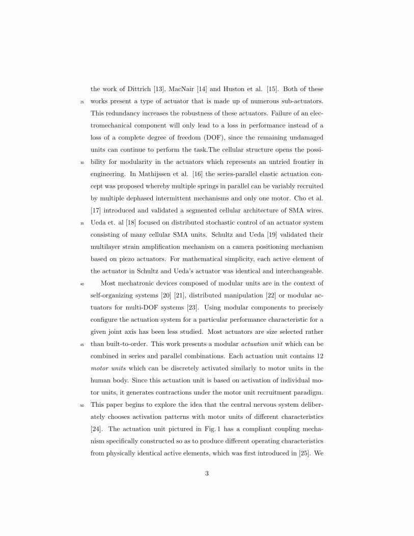
[24]. The actuation unit pictured in Fig. 1 has a compliant coupling mecha-
nism specifically constructed so as to produce different operating characteristics
from physically identical active elements, which was first introduced in [25]. We
3
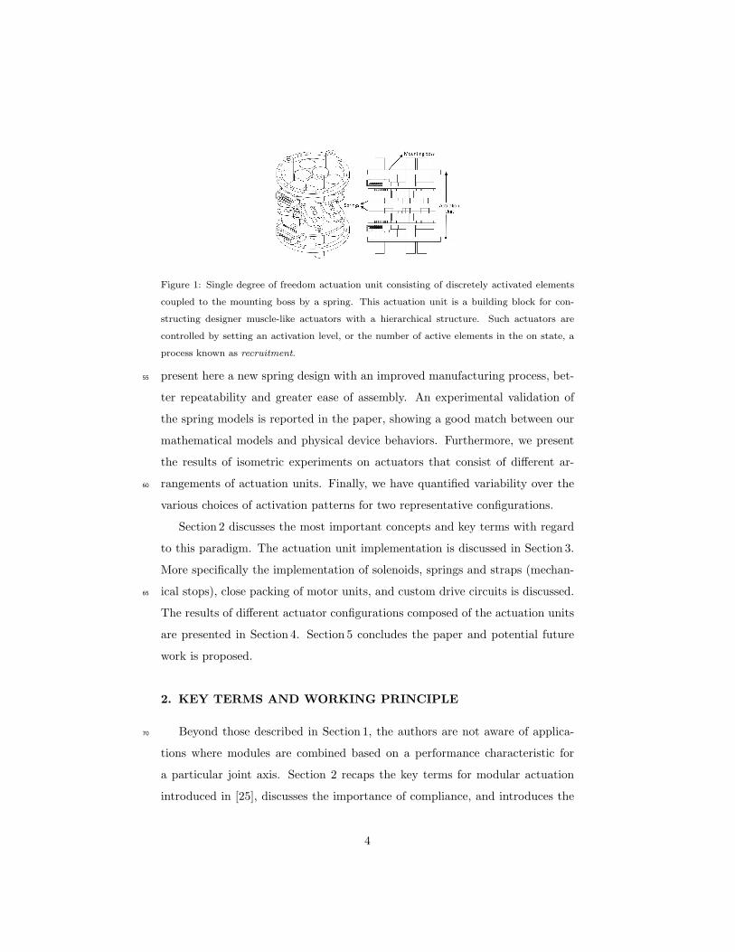
Figure 1: Single degree of freedom actuation unit consisting of discretely activated elements
coupled to the mounting boss by a spring. This actuation unit is a building block for con-
structing designer muscle-like actuators with a hierarchical structure. Such actuators are
controlled by setting an activation level, or the number of active elements in the on state, a
process known as recruitment.
present here a new spring design with an improved manufacturing process, bet-55
ter repeatability and greater ease of assembly. An experimental validation of
the spring models is reported in the paper, showing a good match between our
mathematical models and physical device behaviors. Furthermore, we present
the results of isometric experiments on actuators that consist of different ar-
rangements of actuation units. Finally, we have quantified variability over the60
various choices of activation patterns for two representative configurations.
Section 2 discusses the most important concepts and key terms with regard
to this paradigm. The actuation unit implementation is discussed in Section 3.
More specifically the implementation of solenoids, springs and straps (mechan-
ical stops), close packing of motor units, and custom drive circuits is discussed.65
The results of different actuator configurations composed of the actuation units
are presented in Section 4. Section 5 concludes the paper and potential future
work is proposed.
2. KEY TERMS AND WORKING PRINCIPLE
Beyond those described in Section 1, the authors are not aware of applica-70
tions where modules are combined based on a performance characteristic for
a particular joint axis. Section 2 recaps the key terms for modular actuation
introduced in [25], discusses the importance of compliance, and introduces the
4
functional model of the actuation unit shown in Fig. 1.
2.1. Key terms modular actuation75
The following terms are introduced or borrowed (with some license) from
biology, and their specific meanings in the context of this paper delineated:
• Cellular [26] muscle-like actuator: a motion or force producing device
composed of more than one actuation unit and containing more than one
motor unit.80
• Actuation unit: this is a manufacturing distinction. It refers to the
smallest possible unit that can be conveniently added, removed or recon-
figured to adjust the muscle-like actuator’s characteristics.
• Motor unit [11]: this is computational or communication distinction.
It refers to the collection of force-producing devices that can be indepen-85
dently activated or deactivated by a single communication line.
Actuation units’ and motor units’ physical boundaries may coincide, but
are not required to. Several paradigms are delineated in [25]. A schematic of
the paradigm implemented in this paper is shown in Fig. 2a and Fig. 2b. Each
actuation unit consists of multiple motor units, which can be activated inde-90
pendently. The implementation, to be described in Section 3, has each motor
unit corresponding to one solenoid in series with a compliant element. Each
actuation unit has multiple solenoids in parallel.
2.2. Compliance enables discretization
Skeletal muscle fibers are arranged in parallel in sufficient numbers to gener-95
ate the required force. A single muscle fiber does not necessarily run the entire
length of the muscle, so series connections are also important [27]. The same
reasoning is valid for modular actuators where actuation units are connected in
series and parallel. The compliance between these units is indispensable to the
operation of a modular actuator. This can be understood by a thought exper-100
iment: take two units tied together in parallel with no compliant interface but
5
Actuation Unit
Spring Element
(a) A muscle-like actuator consisting
of modular actuation units.
Inactive
Active: strong
motor unit
Active: weak
motor unit
(b) Each actuation unit has multiple active ele-
ments, e.g. solenoids, each controlled by a signal
line.
Figure 2: Visualization of the paradigm implemented in this paper. Each actuation unit
consists of multiple motor units. The signal lines to inactive motor units have been omitted
for clarity.
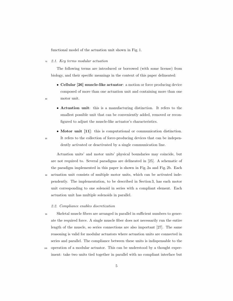
instead a rigid end cap. The contraction of one unit would then result in the
same contraction of the other unit. Any other case would violate the compat-
ibility condition of mechanics of materials [28]. This is indicated in Fig. 3. By
connecting a contractile unit (analogous to a muscle fiber) through a compli-105
ant connection, rather than a rigid one, the compatibility condition is satisfied.
Instead of requiring displacements to be equal, the compliant material imposes
a mathematical relationship between displacement and the force contribution
of that fiber. In skeletal muscle, the fibers are instead connected together by
endomysial connective tissue [27], which is elastic. In modular actuation units,110
this elastic force-displacement relationship can be exploited and specified so as
to obtain desirable properties for the muscle-like actuator as a whole.
Figure 3: The compliant element is crucial to allow different contraction patterns amongst
actuation units. The three most left configurations do not include a compliant element. The
third figure indicates the inconsistency, which is resolved by the compliant element in the
fourth figure.
6
2.3. Working principle of an actuation unit
The working principle of an actuation unit of the type described in this work
is explained by means of the functional model in Fig. 4. This is an example of115
the paradigm in Fig. 2. The implementation is further explained in Section 3.
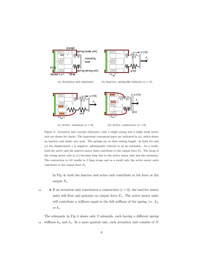
Each functional part of the actuation unit schematic is indicated in Fig. 4a.
For clarity, the schematic consists of only 2 parallel solenoids which function
as the motor units; in practice, any number may be present. Since a solenoid
is a unidirectional actuator, the actuation unit is unidirectional as well. Both120
solenoids are fixed to a printed circuit board (PCB) and connected to an exten-
sion spring with different stiffness, further referred to as the weak motor unit
and the strong motor unit. The stiffness of each spring is named kw and ks re-
spectively. The stroke Lx of the solenoid is indicated as well. When the plunger
is pulled away from the coil, a strap becomes taut and prevents the plunger125
from separating from the coil. Each strap is fixed to the PCB and to the middle
of one of the springs. The ends of the springs opposite of the plunger are fixed
to the mounting boss. When a solenoid contracts it deforms the spring, which
results in a force at the mounting boss. Each combination of a solenoid and a
spring can, as such, be considered an SEA. Adjacent actuation units connect at130
the mounting boss and ultimately, to the robotic link itself.
The working principle of an actuation unit will be explained via Fig. 4b-4c.
• If an actuation unit experiences an extension (x < 0) as in Fig. 4b and
Fig. 4c, both active and inactive motor units contribute to the force at the
mounting boss. An inactive motor unit will behave as spring due to the135
taut strap. Each spring whose strap is engaged will have a stiffness equal
to a fraction f of the stiffness of the spring, i.e. f kw or f ks (0 < f < 1),
depending on the connection of the strap to the springs, which determines
the number of springs that can extend. The connection of the strap differs
from that in [25]. An active motor unit will contribute with a stiffness140
equal to the full stiffness of the spring, i.e. kw or ks. In Fig. 4b both
units are inactive and behave like a spring with stiffness f kw and f ks.
7
coil
PCB
mounting
boss
plunger
spring (weak unit)
spring (strong unit)
LxStroke Strap
(a) Actuation unit schematic.
L
a
x
x=0
(b) Inactive: spring-like behavior (x < 0).
Lx
a
x
x ( )
(c) Active: extension (x < 0).
Lx
x ( )
a
x
(d) Active: contraction (x > 0).
Figure 4: Actuation unit concept schematic; only a single strong and a single weak motor
unit are shown for clarity. The important conceptual parts are indicated in (a), which shows
an inactive unit under zero load. The springs are at their resting length. In both (b) and
(c) the displacement x is negative, subsequently referred to as an extension. As a result,
both the active and the inactive motor units contribute to the output force Fa. The strap of
the strong motor unit in (c) becomes limp due to the active motor unit and the extension.
The contraction in (d) results in 2 limp straps and as a result only the active motor units
contribute to the output force Fa.
In Fig. 4c both the inactive and active unit contribute to the force at the
output Fa.
• If an actuation unit experiences a contraction (x > 0), the inactive motor145
units will float and generate no output force Fa. The active motor units
will contribute a stiffness equal to the full stiffness of the spring, i.e. kw
or ks
The schematic in Fig. 4 shows only 2 solenoids, each having a different spring
stiffness kw and ks. In a more general case, each actuation unit consists of N150
8
motor units, of which N2
motor units have a spring stiffness ks and N2
motor
units have a spring stiffness kw. All solenoids are identical; functionally they
act as a displacement source. The characteristics of the spring element a given
solenoid is connected to determines whether it is a strong or weak motor unit.
The spring path to the mounting boss is stiffer for the strong motor unit than155
for the weak, resulting in a higher force for the same solenoid displacement. It
is easy to generalize this concept to actuators which posses finite numbers of
actuation levels greater than 2; there would simply be more grades of stiffness.
Ideally, the geometry is chosen such that
kweak = r kstrong, r ∈ R/Q, 0 < r < 1 (1)
where kweak and kstrong are effective spring constants from the active material to160
the load and r is an irrational proportionality constant. For the actuation units
described in this paper the aim was r = 1/√2. This prevents the contribution
of small numbers of strong motor units from being identical to that of larger
numbers of weak motor units, conserving a greater richness of potential control
inputs while producing only a modest reduction in blocked force.165
The output force of an actuation unit Fa depends on how many and which
type of motor units (weak or strong) are activated. The number of active motor
units is named M , and the number of strong and weak active motor units Ms
and Mw, respectively. Fa also depends on the displacement x of the mounting
boss and the stroke of the solenoid Lx. Taken together, Fa can be described by170
Eq. (2). For x ≥ 0 Eq. (2) consists of 1 term, which represents the contribution
of the active motor units. The inactive motor units do not contribute since the
straps are not taut for x ≥ 0, which is the case in Fig. 4c and Fig. 4d. The
additional term in Eq. (2) for x < 0 represents the contribution of the inactive
motor units. Since the straps are taut here, the extra factor f must be taken175
9
into account.
F =
(Lx − x) (Mw kw +Ms ks), x ≥ 0
(Lx − x) (Mw kw +Ms ks) − x(
(N2−Mw) f kw + (N
2−Ms) f ks
)
, x < 0
(2)
It should be noted that selecting a specific activation pattern also results in
a change in stiffness of the actuator. Depending on which motor units (strong
or weak) and how many are activated, and which straps and how many are
taut, the stiffness of the actuator will change. Rigorous study of this property180
is beyond the scope of this article and will be addressed in a future work.
3. ACTUATION UNIT IMPLEMENTATION
In this section the physical implementation of the actuation units is dis-
cussed. The general schematic of an actuation unit, discussed in the previous
Section 2.3, consists of one PCB and N solenoids with N2
strong and N2
weak185
motor units. As defined in Section 2.1, the term actuation unit is a manufac-
turing distinction. In this work, two PCBs with 6 solenoids each (3 weak and
3 strong motor units) are combined to form an actuation unit. The mounting
boss corresponding to each PCB is fixed to the adjacent actuation unit. The
following main parts of an actuation unit will be discussed in the subsections190
hereafter: solenoids which should be arranged optimally, springs and straps,
and the custom drive circuit.
3.1. Solenoids
The contractile element of the motor unit is a miniature solenoid; each ac-
tuation unit contains twelve. This solenoid is produced by the Line Electric195
Company, S. Glastonbury, CT, USA, and claims to be “the world’s smallest
solenoid”. The form factor of this solenoid is the same as a TO-5 transistor
package and is particularly suited to the construction of compact actuation
units. Performance specifications of the solenoid are listed in Table 1. Each
10
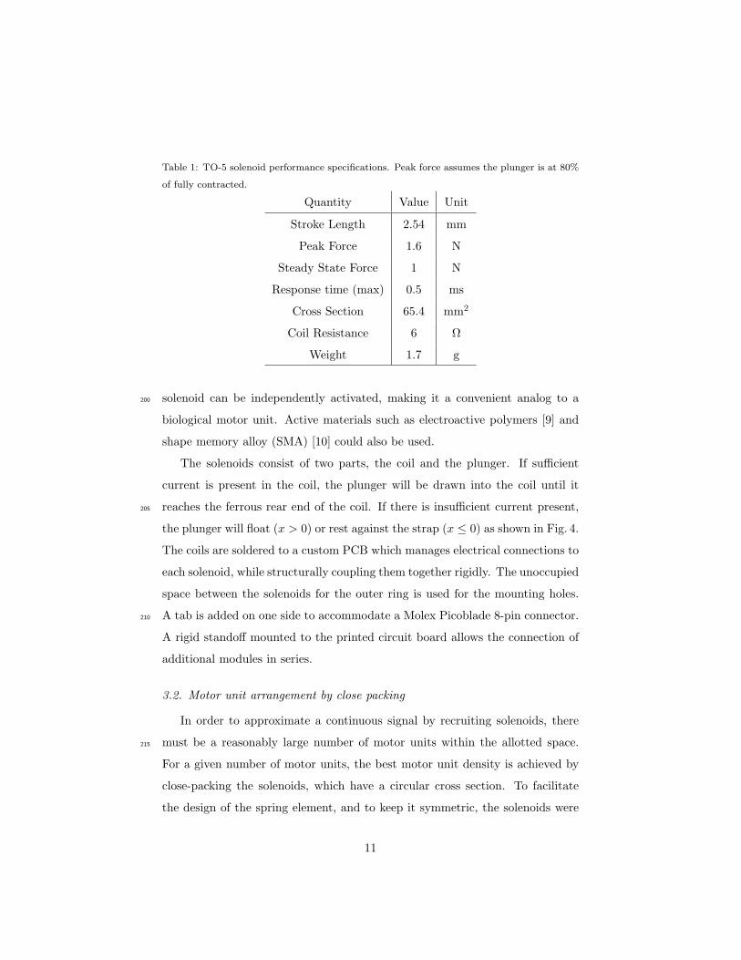
Table 1: TO-5 solenoid performance specifications. Peak force assumes the plunger is at 80%
of fully contracted.
Quantity Value Unit
Stroke Length 2.54 mm
Peak Force 1.6 N
Steady State Force 1 N
Response time (max) 0.5 ms
Cross Section 65.4 mm2
Coil Resistance 6 Ω
Weight 1.7 g
solenoid can be independently activated, making it a convenient analog to a200
biological motor unit. Active materials such as electroactive polymers [9] and
shape memory alloy (SMA) [10] could also be used.
The solenoids consist of two parts, the coil and the plunger. If sufficient
current is present in the coil, the plunger will be drawn into the coil until it
reaches the ferrous rear end of the coil. If there is insufficient current present,205
the plunger will float (x > 0) or rest against the strap (x ≤ 0) as shown in Fig. 4.
The coils are soldered to a custom PCB which manages electrical connections to
each solenoid, while structurally coupling them together rigidly. The unoccupied
space between the solenoids for the outer ring is used for the mounting holes.
A tab is added on one side to accommodate a Molex Picoblade 8-pin connector.210
A rigid standoff mounted to the printed circuit board allows the connection of
additional modules in series.
3.2. Motor unit arrangement by close packing
In order to approximate a continuous signal by recruiting solenoids, there
must be a reasonably large number of motor units within the allotted space.215
For a given number of motor units, the best motor unit density is achieved by
close-packing the solenoids, which have a circular cross section. To facilitate
the design of the spring element, and to keep it symmetric, the solenoids were
11
placed in two concentric rings, with the strong motor units in the outer ring, and
the weak ones in the inner ring. This is advantageous from a power standpoint,220
because the stronger motor units will require more current. Placing them on
the outside will better allow them to dissipate heat. This is not a biologically
inspired arrangement; the situation in biology is much more complicated and is
motivated by additional factors not represented in this design, such as routing
of nerves and blood vessels. In fact, the individual muscle fibers from various225
motor units are interspersed with one another [29].
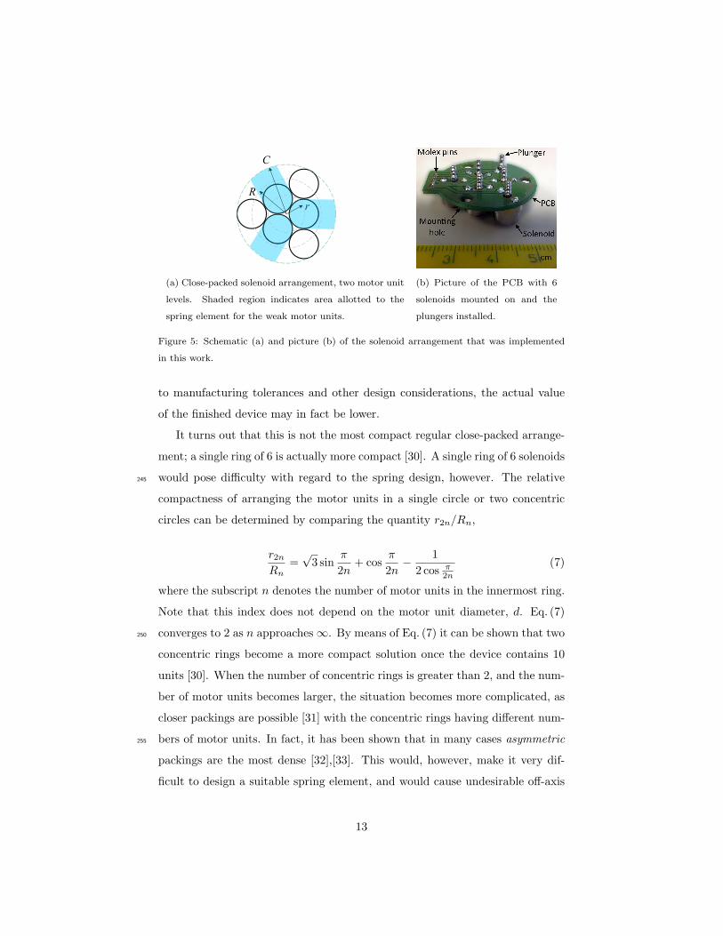
The smallest non-trivial example contains 6 motor units: 3 strong and 3
weak motor units. This arrangement is illustrated in Fig. 5a. The centroids of
the inner ring of solenoids lie on a circle of radius r, and the centroids of the
outer ring of solenoids lie on a circle of radius R. The circumscribing circle of230
the outermost ring, of radius C, represents the minimum theoretical radius of
any actuator of this type. They can be calculated from the number of solenoids
as follows:
r =d
2 sin πn
(3)
R =d√3
2+ r cos
π
n(4)
C = R+d
2(5)
where d denotes the diameter of the solenoid, and n denotes the number of
solenoids in the inner ring. Thus the motor unit density per unit area for this235
configuration, σ, can be calculated as:
σ =n
πC2. (6)
This can be used as a metric to evaluate the relative merits of a given muscle-like
solution and helps the designer answer the following question: Is the actuator
getting larger in order to increase the control resolution or the actuator maxi-
mum force? It should be noted that Eq. (6) is only a theoretical value, and due240
12
r
R
C
R
r
(a) Close-packed solenoid arrangement, two motor unit
levels. Shaded region indicates area allotted to the
spring element for the weak motor units.
(b) Picture of the PCB with 6
solenoids mounted on and the
plungers installed.
Figure 5: Schematic (a) and picture (b) of the solenoid arrangement that was implemented
in this work.
to manufacturing tolerances and other design considerations, the actual value
of the finished device may in fact be lower.
It turns out that this is not the most compact regular close-packed arrange-
ment; a single ring of 6 is actually more compact [30]. A single ring of 6 solenoids
would pose difficulty with regard to the spring design, however. The relative245
compactness of arranging the motor units in a single circle or two concentric
circles can be determined by comparing the quantity r2n/Rn,
r2nRn
=√3 sin
π
2n+ cos
π
2n− 1
2 cos π2n
(7)
where the subscript n denotes the number of motor units in the innermost ring.
Note that this index does not depend on the motor unit diameter, d. Eq. (7)
converges to 2 as n approaches ∞. By means of Eq. (7) it can be shown that two250
concentric rings become a more compact solution once the device contains 10
units [30]. When the number of concentric rings is greater than 2, and the num-
ber of motor units becomes larger, the situation becomes more complicated, as
closer packings are possible [31] with the concentric rings having different num-
bers of motor units. In fact, it has been shown that in many cases asymmetric255
packings are the most dense [32],[33]. This would, however, make it very dif-
ficult to design a suitable spring element, and would cause undesirable off-axis
13
bending and possible alignment issues in manufacturing and operation.
The space within the envelope (be it a circle of radius C or otherwise) cir-
cumscribing the motor units but not occupied by the solenoids themselves is260
not necessarily wasted space. In some cases, this space could be used for drive
electronics, sensing, or computational elements, making the device more of an
integrated solution.
3.3. Springs and straps
The spring element is not simply a series elastic element, but rather is crucial265
to the operation of the device, as it allows some solenoids to be active and others
inactive at the same time. As alluded to in Section 2.2, the spring element
serves several functions: it combines the various efforts of the motor units at
the output, presents a compliant interface with the environment, and since
the solenoids correspond to a displacement source, determines which solenoids270
correspond to strong motor units and which correspond to weak motor units.
The selection of this spring element represents a significant engineering chal-
lenge, because it must accomplish the following objectives. It must:
• Not significantly decrease the strain rate ǫ of the actuator.
• Not interfere mechanically with other motor units when transitioned be-275
tween the active and inactive states.
• Be able to be manufactured without using exotic or costly manufacturing
techniques.
• Fit within (or at least not greatly exceed the dimensions of) the circum-
scribing circle of radius C, described in Section 3.2.280
Each of these objectives becomes more difficult to accomplish with decreasing
size. To maximize the strain rate, the spring element should be as thin as
possible in the actuation direction. The following Sections 3.3.1 and 3.3.2 report
on two custom made designs based on different manufacturing techniques: a wire
form spring and a leaf spring. The wire form spring was presented in [25]. In285
14
Section 3.3.1 the connection issues of the lobes to form the wire form spring are
discussed as well. In Section 3.3.2 the leaf spring, an improved spring design, is
introduced and the characterization experiments are reported. In Section 3.3.3
the implementation of the straps is delineated.
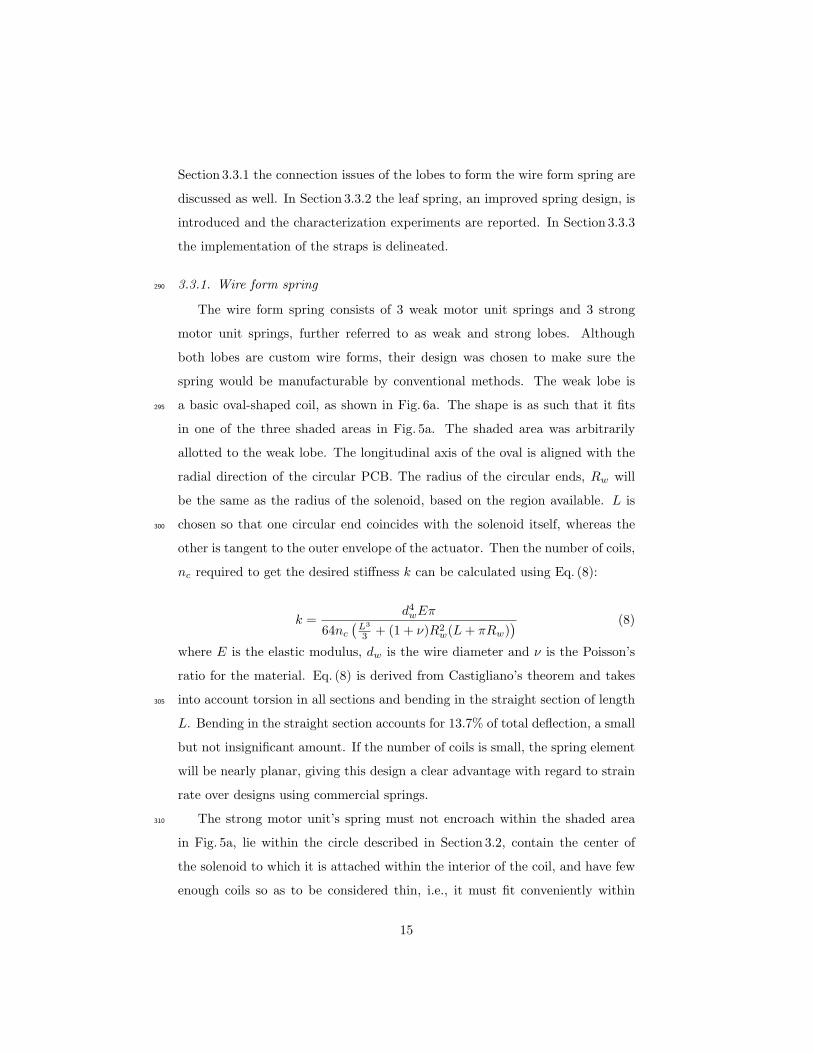
3.3.1. Wire form spring290
The wire form spring consists of 3 weak motor unit springs and 3 strong
motor unit springs, further referred to as weak and strong lobes. Although
both lobes are custom wire forms, their design was chosen to make sure the
spring would be manufacturable by conventional methods. The weak lobe is
a basic oval-shaped coil, as shown in Fig. 6a. The shape is as such that it fits295
in one of the three shaded areas in Fig. 5a. The shaded area was arbitrarily
allotted to the weak lobe. The longitudinal axis of the oval is aligned with the
radial direction of the circular PCB. The radius of the circular ends, Rw will
be the same as the radius of the solenoid, based on the region available. L is
chosen so that one circular end coincides with the solenoid itself, whereas the300
other is tangent to the outer envelope of the actuator. Then the number of coils,
nc required to get the desired stiffness k can be calculated using Eq. (8):
k =d4wEπ
64nc
(
L3
3+ (1 + ν)R2
w(L+ πRw)) (8)
where E is the elastic modulus, dw is the wire diameter and ν is the Poisson’s
ratio for the material. Eq. (8) is derived from Castigliano’s theorem and takes
into account torsion in all sections and bending in the straight section of length305
L. Bending in the straight section accounts for 13.7% of total deflection, a small
but not insignificant amount. If the number of coils is small, the spring element
will be nearly planar, giving this design a clear advantage with regard to strain
rate over designs using commercial springs.
The strong motor unit’s spring must not encroach within the shaded area310
in Fig. 5a, lie within the circle described in Section 3.2, contain the center of
the solenoid to which it is attached within the interior of the coil, and have few
enough coils so as to be considered thin, i.e., it must fit conveniently within
15
the remaining available space. The natural shape to fit the space is an oval,
but with the longitudinal axis perpendicular to the radial direction rather than315
aligned with it.
(a) 1 weak and 1 strong lobe.
Manufactured in 1 piece.
(b) 3 pairs of 1 weak and
1 strong lobe, connected to-
gether to form the spring.
(c) Picture of the wire
form spring.
Figure 6: Drawings and a picture of the wire form spring introduced in [25].
The spring constant relationships are described by Eq. (8), with Rw and L
free parameters, as well as the oval’s center, that can be used to select spring
performance subject to the constraints. A numerical constrained optimization
was conducted to determine the values that give the coil geometry with the320
minimum number of coils for the desired stiffness. The result, not surprisingly,
is a circle (L = 0) tangent to the outer boundary circle and the boundaries of
the shaded region (Rw = 5.58mm). The required nc is 1.6.
The selected wire diameter is 25AWG or 0.455mm. This resulted in a theo-
retical strong lobe stiffness of 0.1926 Nmm
and a weak lobe stiffness of 0.1352 Nmm
.325
The deflection predicted by Eq. (8) agrees with that predicted by finite element
methods within 19%, indicating that the model described by Eq. (8) is useful
for constructing a spring element that a spring element that will give close to
the maximum holding force of the solenoid without overheating. The custom
wire forms are provided by the Active Spring Company, Sibley’s Green, United330
Kingdom.
One disadvantage is that the complete wire form spring (with 6 lobes) cannot
be manufactured in a single piece, in a single operation. In this implementation
3 wire forms, each containing one strong lobe and one weak lobe need to be
16
connected. This was done by M1 screws and a precisely manufactured clamp,335
and later by a micro welding process. Although feasible and validated empir-
ically, both techniques are unreliable and significantly increase the complexity
of the wire form spring. The clamp needs to be of high precision since the wire
diameter is small and is fastened by M1 screws. The micro welding degrades
the metallurgical qualities of the springs. Furthermore, the repeatability of the340
manufacturing process (including the connection) is rather low and clear differ-
ences could be observed. Finally, the adjustment cost to produce a variant of
the wire form spring is relatively high. The aforementioned issues motivated us
to search for modifications that would improve manufacturing consistency and
efficiency of the process. Therefor, the next Section 3.3.2 discusses a new spring345
design that solves the encountered issues of the wire form spring.
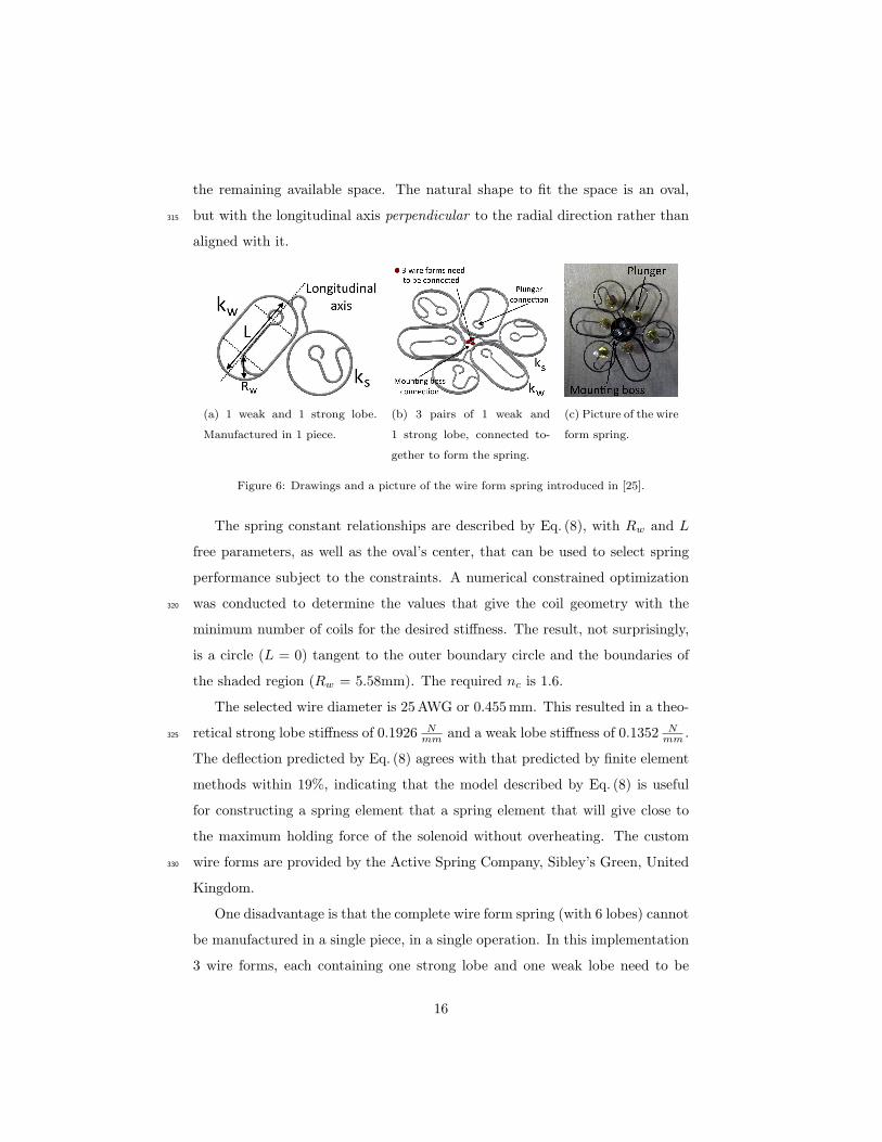
3.3.2. Novel leaf spring
The general idea is to have a central hub, from which 6 beams emanate
toward each solenoid. The spring, with 6 lobes, is laser–cut in a single piece out
of a thin spring steel sheet. This process proved to be highly repeatable and350
precise. Furthermore, the laser cutting technique allows for easy connection to
the straps, mounting boss and plungers as indicated in Fig. 7b. The challenge is
to make the beams compliant enough, since the actuator diameter is small and
thus the beams cannot be long, increasing the bending stiffness. Furthermore,
the space is limited so the lobes cannot bend back and forth many times in355
the plane. In order to retain the same compact solenoid arrangement, a drop-
in replacement for the wire spring was required, placing additional constraints
on the design. Appropriate stiffness and extension can, however, be achieved
by laser cutting U-shaped lobes out of a 0.1mm thin 1.413 Chromium-nickel
austenitic stainless spring steel plate (AISI 301). A schematic and picture are360
shown in Fig. 7. The precise lasers of Raytech, Brugge, Belgium allowed for a
lobe width w of 2.4mm. The density ρ of AISI 301 steel is 7900 kg/m3, elastic
modulus E of 189GPa, yield strength σy of 1072MPa and tensile strength σt of
1309MPa. A schematic of the leaf spring design and illustration of the lengths
17
(a) Leaf spring schematic in-
dicating the design parame-
ters.
(b) Picture of the leaf spring
indicating the connections
to plungers and mounting
boss.
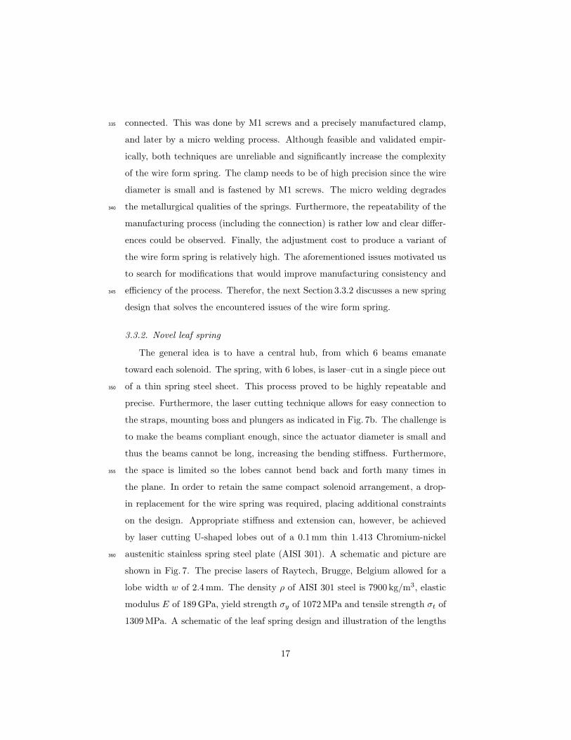
Figure 7: Leaf spring design with 6 U-shaped lobes cut out of a 0.1mm spring steel sheet.
of the weak and strong U-shaped lobes, Lw1, Lw2, Ls1 and Ls2, is shown in365
Fig. 7a.
The analytical model to calculate the force produced by a lobe Flobe as a
function of the extension ∆x, consists of standard beam bending of both of the
legs of the spring as shown in Eq. (9). It is assumed that the vertical force Flobe
applied at the plunger connection and the bend of the U-shape. Euler-Bernoulli
bending in the straight sections is assumed, and deformations in the curved
sections are neglected.
Flobe = ∆x3E I
L13
+∆x3E I
L23
(9)
As noted in Table 1, the maximum steady state force of the TO-5 solenoid
is 1N when fully contracted. Over a stroke length of 2.54mm this results in a
maximum linear spring stiffness of 0.39N/mm. A safety factor of 3 is included
to account for potential friction in the system. The turn of the U-shaped lobe is370
slightly larger than the PCB to allow for connection to the straps. Taking into
account these goals and geometrical constraints, the parameters of the strong
and weak lobe were tuned which resulted in the following specifications:
• Strong lobe: w=2.4mm, Ls1=9.9mm, Ls2=7.5mm. Theoretical stiffness:
0.13N/mm.375
18
0 0.5 1 1.5 2 2.50
0.2
0.4
0.6
0.8
1
Extension (mm)
Out
put f
orce
(N
)
Exp: 3 strongExp: 3 weakTheory: 3 strongTheory: 3 weak
(a) Leaf spring w = 2.4mm.
0
100
200
300
400
500
600
w = 2.4 mm
Stif
fnes
s k s &
kw
(N
/m)
Exp: 3 weakTheory: 3 weakExp: 3 strongTheory: 3 strong
0
0.5
1
1.5
2
w = 2.4 mm
Rat
io: k
s/ kw
ExperimentTheory
(b) Compare linear stiffness and stiffness
ratio theoretically and experimentally.
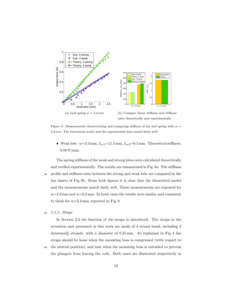
Figure 8: Measurements characterizing and comparing stiffness of the leaf spring with w =
2.4mm. The theoretical model and the experimental data match fairly well.
• Weak lobe: w=2.4mm, Lw1=11.5mm, Lw2=9.1mm. Theoretical stiffness:
0.08N/mm.
The spring stiffness of the weak and strong lobes were calculated theoretically
and verified experimentally. The results are summarized in Fig. 8a. The stiffness
profile and stiffness ratio between the strong and weak lobe are compared in the380
bar charts of Fig. 8b. From both figures it is clear that the theoretical model
and the measurements match fairly well. These measurements are repeated for
w=2.8mm and w=3.2mm. In both cases the results were similar and consistent
to those for w=2.4mm, reported in Fig. 8.
3.3.3. Straps385
In Section 2.3 the function of the straps is introduced. The straps in the
actuation unit presented in this work are made of 4 strand braid, including 3
dyneema R© strands, with a diameter of 0.25mm. As explained in Fig. 4 the
straps should be loose when the mounting boss is compressed (with respect to
the neutral position), and taut when the mounting boss is extended to prevent390
the plungers from leaving the coils. Both cases are illustrated respectively in
19
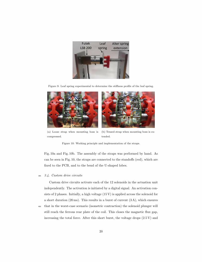
Figure 9: Leaf spring experimental to determine the stiffness profile of the leaf spring.
(a) Loose strap when mounting boss is
compressed.
(b) Tensed strap when mounting boss is ex-
tended.
Figure 10: Working principle and implementation of the straps.
Fig. 10a and Fig. 10b. The assembly of the straps was performed by hand. As
can be seen in Fig. 10, the straps are connected to the standoffs (red), which are
fixed to the PCB, and to the bend of the U-shaped lobes.
3.4. Custom drive circuits395
Custom drive circuits activate each of the 12 solenoids in the actuation unit
independently. The activation is initiated by a digital signal. An activation con-
sists of 2 phases. Initially, a high voltage (15V) is applied across the solenoid for
a short duration (20ms). This results in a burst of current (3A), which ensures
that in the worst-case scenario (isometric contraction) the solenoid plunger will400
still reach the ferrous rear plate of the coil. This closes the magnetic flux gap,
increasing the total force. After this short burst, the voltage drops (2.5V) and
20
a steady state current of 0.5A ensures the plunger is held in the solenoid coil
while avoiding overheating of the coil.
The custom drive circuits are activated and deactivated by means of digital405
I/O lines of the National Instruments USB-6501 DAQ modules. One actuation
unit requires 12 digital I/O lines to independently control the 12 solenoids. The
DAQ modules can be controlled by a Labview interface or matlab code.
4. EXPERIMENTAL VALIDATION OF ACTUATION UNITS
The aim of this Section 4 is to study the isometric output force of the ac-410
tuation units in several representative configurations. More specifically, a chain
of 4 units in series (further referred to as 1x4 actuator) will be compared to
a bundle of 2 parallel chains of 2 actuation units (further referred to as 2x2
actuator). A study on the repeatability of the output force as a function of the
activation patterns is presented as well.415
4.1. Experimental set-up and activation graph
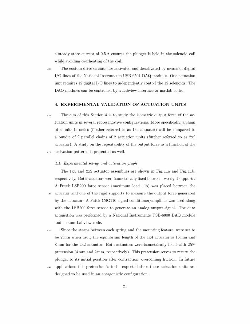
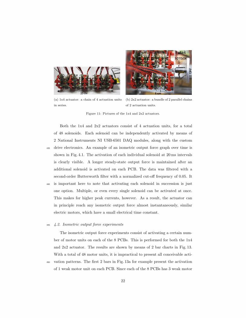
The 1x4 and 2x2 actuator assemblies are shown in Fig. 11a and Fig. 11b,
respectively. Both actuators were isometrically fixed between two rigid supports.
A Futek LSB200 force sensor (maximum load 1 lb) was placed between the
actuator and one of the rigid supports to measure the output force generated420
by the actuator. A Futek CSG110 signal conditioner/amplifier was used along
with the LSB200 force sensor to generate an analog output signal. The data
acquisition was performed by a National Instruments USB-6000 DAQ module
and custom Labview code.
Since the straps between each spring and the mounting feature, were set to425
be 2mm when taut, the equilibrium length of the 1x4 actuator is 16mm and
8mm for the 2x2 actuator. Both actuators were isometrically fixed with 25%
pretension (4mm and 2mm, respectively). This pretension serves to return the
plunger to its initial position after contraction, overcoming friction. In future
applications this pretension is to be expected since these actuation units are430
designed to be used in an antagonistic configuration.
21
(a) 1x4 actuator: a chain of 4 actuation units
in series.
(b) 2x2 actuator: a bundle of 2 parallel chains
of 2 actuation units.
Figure 11: Pictures of the 1x4 and 2x2 actuators.
Both the 1x4 and 2x2 actuators consist of 4 actuation units, for a total
of 48 solenoids. Each solenoid can be independently activated by means of
2 National Instruments NI USB-6501 DAQ modules, along with the custom
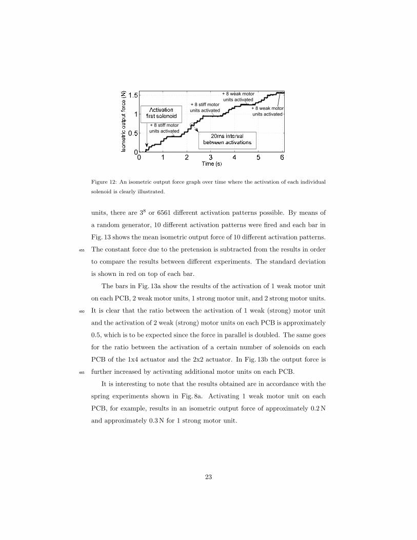
drive electronics. An example of an isometric output force graph over time is435
shown in Fig. 4.1. The activation of each individual solenoid at 20ms intervals
is clearly visible. A longer steady-state output force is maintained after an
additional solenoid is activated on each PCB. The data was filtered with a
second-order Butterworth filter with a normalized cut-off frequency of 0.05. It
is important here to note that activating each solenoid in succession is just440
one option. Multiple, or even every single solenoid can be activated at once.
This makes for higher peak currents, however. As a result, the actuator can
in principle reach any isometric output force almost instantaneously, similar
electric motors, which have a small electrical time constant.
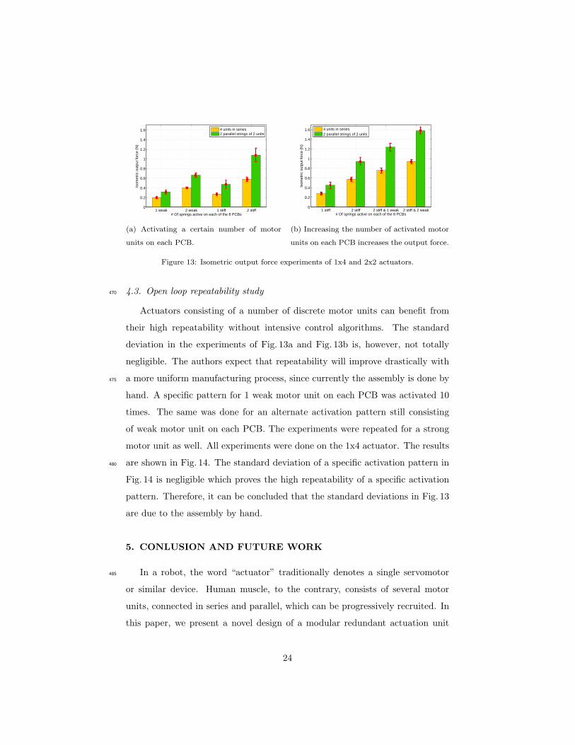
4.2. Isometric output force experiments445
The isometric output force experiments consist of activating a certain num-
ber of motor units on each of the 8 PCBs. This is performed for both the 1x4
and 2x2 actuator. The results are shown by means of 2 bar charts in Fig. 13.
With a total of 48 motor units, it is impractical to present all conceivable acti-
vation patterns. The first 2 bars in Fig. 13a for example present the activation450
of 1 weak motor unit on each PCB. Since each of the 8 PCBs has 3 weak motor
22
0 1 20
0
1
1
20
+ 8 stiff motor
units activated
+ 8 stiff motor
units activated
+ 8 weak motor
units activated
+ 8 weak motor
units activated
Figure 12: An isometric output force graph over time where the activation of each individual
solenoid is clearly illustrated.
units, there are 38 or 6561 different activation patterns possible. By means of
a random generator, 10 different activation patterns were fired and each bar in
Fig. 13 shows the mean isometric output force of 10 different activation patterns.
The constant force due to the pretension is subtracted from the results in order455
to compare the results between different experiments. The standard deviation
is shown in red on top of each bar.
The bars in Fig. 13a show the results of the activation of 1 weak motor unit
on each PCB, 2 weak motor units, 1 strong motor unit, and 2 strong motor units.
It is clear that the ratio between the activation of 1 weak (strong) motor unit460
and the activation of 2 weak (strong) motor units on each PCB is approximately
0.5, which is to be expected since the force in parallel is doubled. The same goes
for the ratio between the activation of a certain number of solenoids on each
PCB of the 1x4 actuator and the 2x2 actuator. In Fig. 13b the output force is
further increased by activating additional motor units on each PCB.465
It is interesting to note that the results obtained are in accordance with the
spring experiments shown in Fig. 8a. Activating 1 weak motor unit on each
PCB, for example, results in an isometric output force of approximately 0.2N
and approximately 0.3N for 1 strong motor unit.
23
1 weak 2 weak 1 stiff 2 stiff0
0.2
0.4
0.6
0.8
1
1.2
1.4
1.6
# Of springs active on each of the 8 PCBs
Isom
etric
out
put f
orce
(N
)
4 units in series2 parallel strings of 2 units
(a) Activating a certain number of motor
units on each PCB.
1 stiff 2 stiff 2 stiff & 1 weak 2 stiff & 2 weak0
0.2
0.4
0.6
0.8
1
1.2
1.4
1.6
# Of springs active on each of the 8 PCBs
Isom
etric
out
put f
orce
(N
)
4 units in series2 parallel strings of 2 units
(b) Increasing the number of activated motor
units on each PCB increases the output force.
Figure 13: Isometric output force experiments of 1x4 and 2x2 actuators.
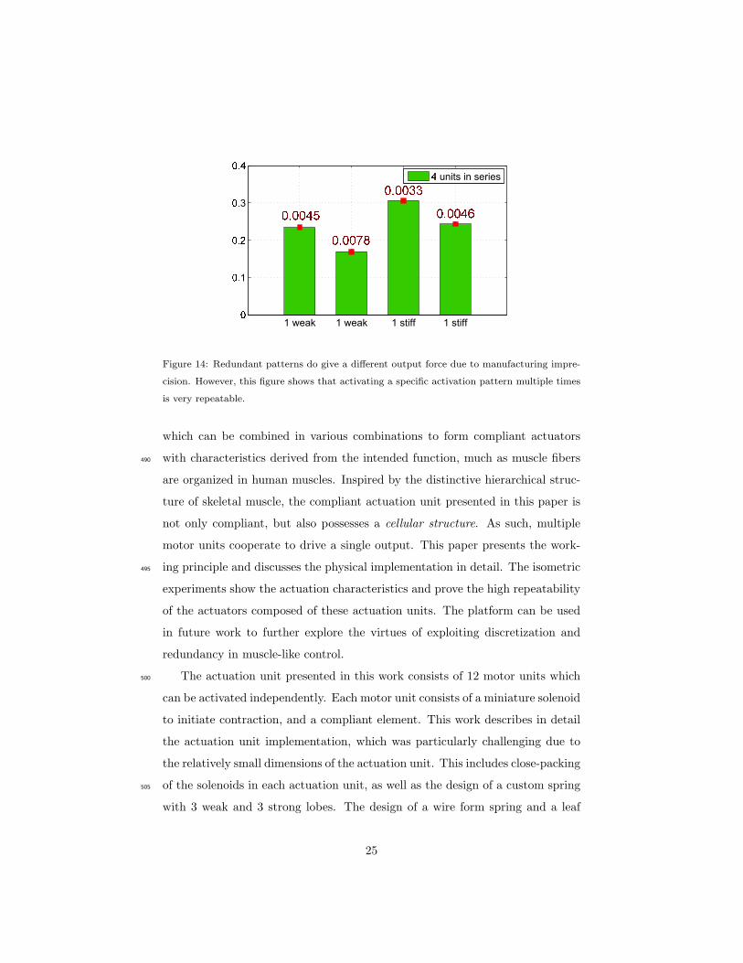
4.3. Open loop repeatability study470
Actuators consisting of a number of discrete motor units can benefit from
their high repeatability without intensive control algorithms. The standard
deviation in the experiments of Fig. 13a and Fig. 13b is, however, not totally
negligible. The authors expect that repeatability will improve drastically with
a more uniform manufacturing process, since currently the assembly is done by475
hand. A specific pattern for 1 weak motor unit on each PCB was activated 10
times. The same was done for an alternate activation pattern still consisting
of weak motor unit on each PCB. The experiments were repeated for a strong
motor unit as well. All experiments were done on the 1x4 actuator. The results
are shown in Fig. 14. The standard deviation of a specific activation pattern in480
Fig. 14 is negligible which proves the high repeatability of a specific activation
pattern. Therefore, it can be concluded that the standard deviations in Fig. 13
are due to the assembly by hand.
5. CONLUSION AND FUTURE WORK
In a robot, the word “actuator” traditionally denotes a single servomotor485
or similar device. Human muscle, to the contrary, consists of several motor
units, connected in series and parallel, which can be progressively recruited. In
this paper, we present a novel design of a modular redundant actuation unit
24
1 weak 1 weak 1 stiff 1 stiff
1
3
units in series
33333
Figure 14: Redundant patterns do give a different output force due to manufacturing impre-
cision. However, this figure shows that activating a specific activation pattern multiple times
is very repeatable.
which can be combined in various combinations to form compliant actuators
with characteristics derived from the intended function, much as muscle fibers490
are organized in human muscles. Inspired by the distinctive hierarchical struc-
ture of skeletal muscle, the compliant actuation unit presented in this paper is
not only compliant, but also possesses a cellular structure. As such, multiple
motor units cooperate to drive a single output. This paper presents the work-
ing principle and discusses the physical implementation in detail. The isometric495
experiments show the actuation characteristics and prove the high repeatability
of the actuators composed of these actuation units. The platform can be used
in future work to further explore the virtues of exploiting discretization and
redundancy in muscle-like control.
The actuation unit presented in this work consists of 12 motor units which500
can be activated independently. Each motor unit consists of a miniature solenoid
to initiate contraction, and a compliant element. This work describes in detail
the actuation unit implementation, which was particularly challenging due to
the relatively small dimensions of the actuation unit. This includes close-packing
of the solenoids in each actuation unit, as well as the design of a custom spring505
with 3 weak and 3 strong lobes. The design of a wire form spring and a leaf
25

spring are discussed in detail.
Two representative actuator configurations are evaluated experimentally, a
chain of 4 units in series and a bundle of 2 parallel chains of 2 actuation units.
Numerous other configurations are conceivable. The experiments corroborate510
the working principle and analytical models of the actuation units. Study of the
repeatability of the output force as a function of the activation patterns showed
high repeatability of the muscle-like actuator.
This actuator module has applications in humanoid robotics, rehabilitation
robotics, and gives roboticists the ability to produce “designer muscles” by515
combining these units in serial and parallel combinations to achieve specific
properties. They are particularly useful in areas where high redundancy is
needed, such as aerospace applications.
Future work includes refinement of the prototype, further miniaturization,
and investigation of discrete-amplitude control strategies for force, displacement,520
and stiffness.
6. Acknowlegdement
This work was supported by ERC-291166-SOFTHANDS and ERC-337596-
SPEAR. Glenn Mathijssen is funded by PhD Fellowship of the Research Foun-
dation - Flanders (FWO).525
The authors would like to thank Phil Hudson, Marco Migliorini, Gianluca
Pane, Manuel Catalano, Nikos Tsagarakis and Stefano Cordasco for invaluable
design suggestions and manufacturing support. The authors would like to thank
Tom Van der Hoeven as well for his help with the experiments.
References530
[1] G. A. Pratt, M. M. Williamson, Series elastic actuators, in: IEEE/RSJ In-
ternational Conference on Intelligent Robots and Systems (IROS): Human
Robot Interaction and Cooperative Robots, Vol. 1, 1995, pp. 399–406.
26
[2] R. Filippini, S. Sen, A. Bicchi, Toward soft robots you can depend on,
IEEE Robotics & Automation Magazine 10 (3) (2008) 31–41.535
[3] A. Jafari, N. G. Tsagarakis, D. G. Caldwell, A novel intrinsically energy ef-
ficient actuator with adjustable stiffness (awas), IEEE/ASME Transactions
on Mechatronics 18 (1) (2013) 355–365.
[4] B. Vanderborght, A. Albu-Schaffer, A. Bicchi, E. Burdet, D. Caldwell,
R. Carloni, M. Catalano, O. Eiberger, W. Friedl, G. Gowrishankar,540
M. Garabini, M. Grebenstein, G. Grioloi, S. Haddadin, M. Laffranchi,
H. Hoppner, A. Jafari, D. Lefeber, F. Petit, S. Stramigioli, N. Tsagarakis,
M. Van Damme, R. Van Ham, L. V. Visser, S. Wolf, Variable Impedance
Actuators: a Review, Robotics and Autonomous Systems 61 (12) (2014)
1601–11614.545
[5] A. Bicchi, G. Tonietti, M. Bavaro, M. Piccigallo, Variable stiffness actuators
for fast and safe motion control, International Journal of Robotics Research
(2005) 527–536.
[6] B. Vanderborght, B. Verrelst, R. Van Ham, M. Van Damme, P. Beyl,
D. Lefeber, Development of a compliance controller to reduce energy con-550
sumption for bipedal robots, Autonomous Robots 24 (4) (2008) 419–434.
[7] D. Villegas, M. Van Damme, B. Vanderborght, P. Beyl, D. Lefeber, Third-
generation pleated pneumatic artificial muscles for robotic applications:
Development and comparison with mckibben muscle, Advanced Robotics
26 (11-12) (2012) 1205–1227.555
[8] P. Brochu, Q. Pei, Advances in dielectric elastomers for actuators and arti-
ficial muscles, Macromolecular Rapid Communications 31 (1) (2010) 10–36.
[9] F. Carpi, R. Kornbluh, P. Sommer-Larsen, G. Alici, Electroactive polymer
actuators as artificial muscles: are they ready for bioinspired applications?,
Bioinspiration & biomimetics 6 (4) (2011) 045006.560
27
[10] E. Torres-Jara, K. Gilpin, J. Karges, R. Wood, D. Rus, Composable flexible
small actuators built from thin shape memory alloy sheets, IEEE Robotics
& Automation Magazine 17 (4) (2010) 78–87.
[11] R. Enoka, Neuromechanics of Human Movement, 3rd Edition, Human Ki-
netics, Champaign, IL, 2002.565
[12] E. Henneman, Relation between size of neurons and their susceptibility to
discharge, Science 126 (3287) (1957) 1345–1347.
[13] K. Dittrich, Patent EADS Deutschland GmbH, Ottobrunn, DE: Cellular
actuator device and methods of making and using the same (2006).
[14] D. MacNair, J. Ueda, Dynamic cellular actuator arrays and the expanded570
fingerprint method for dynamic modeling, Robotics and Autonomous Sys-
tems 62 (7) (2014) 1060 – 1072.
[15] D. Huston, B. Esser, G. Spencer, D. Burns, E. Kahn, Hierarchical actuator
systems, Proceedings of SPIE 5762 (2005) 311–319.
[16] G. Mathijssen, D. Lefeber, B. Vanderborght, Variable recruitment of par-575
allel elastic elements: Series-parallel elastic actuators (spea) with dephased
mutilated gears, IEEE Transactions on Mechatronics (in press) PP (2014)
1–9.
[17] K. Cho, H. Asada, Architecture design of a multiaxis cellular actuator array
using segmented binary control of shape memory alloy, IEEE Transactions580
on Robotics 22 (4) (2006) 831–843.
[18] J. Ueda, L. Odhner, H. H. Asada, Broadcast Feedback of Stochastic Cellular
Actuators Inspired by Biological Muscle Control, The International Journal
of Robotics Research 26 (11-12) (2007) 1251–1265.
[19] J. A. Schultz, J. Ueda, Nested piezoelectric cellular actuators for a bio-585
logically inspired camera positioning mechanism, IEEE Transactions on
Robotics 29 (5) (2013) 1125–1138.
28
[20] Z. Butler, D. Rus, Distributed planning and control for modular robots with
unit-compressible modules, The International Journal of Robotics Research
22 (9) (2003) 699–715.590
[21] C. J. Paredis, H. Benjamin Brown, P. K. Khosla, A rapidly deployable
manipulator system, Robotics and Autonomous Systems 21 (3) (1997) 289–
304.
[22] H. Oyobe, Y. Hori, Object conveyance system magic carpet? consisting
of 64 linear actuators-object position feedback control with object posi-595
tion estimation, in: IEEE/ASME International Conference on Advanced
Intelligent Mechatronics (AIM), Como, 2001, pp. 1307–1312.
[23] M. G. Catalano, G. Grioli, M. Garabini, F. Bonomo, M. Mancinit,
N. Tsagarakis, A. Bicchi, Vsa-cubebot: A modular variable stiffness plat-
form for multiple degrees of freedom robots, in: IEEE International Con-600
ference on Robotics and Automation (ICRA), 2011, pp. 5090–5095.
[24] H. Milner-brown, R. Stein, R. Yemm, The orderly recruitment of human
motor units during voluntary isometric contractions, Journal of Physiology
230 (2) (1973) 359–370.
[25] J. Schultz, G. Mathijssen, B. Vanderborght, A. Bicchi, Toward motor-unit-605
recruitment actuators for soft robotics, in: RAS and EMBS International
Conference on Biomedical Robotics and Biomechatronics (BioRob), 2014,
pp. 887–892.
[26] J. Ueda, T. W. Secord, H. H. Asada, Large effective-strain piezoelectric
actuators using nested cellular architecture with exponential strain ampli-610
fication mechanisms, IEEE/ASME Transactions on Mechatronics 15 (5)
(2010) 770–782.
[27] R. Lieber, J. Friedn, Functional and clinical significance of skeletal muscle
architecture, Muscle & nerve 23 (2000) 1647–1666.
29
[28] J. M. Gere, B. J. Goodno, Mechanics of Materials, 8th Edition, Cengage615
Learning, Stamford, CT, 2013.
[29] L. Edstrom, E. Kugelberg, Histochemical composition, distribution of fibres
and fatiguability of single motor units. Anterior tibial muscle of the rat.,
Journal of neurology, neurosurgery, and psychiatry 31 (5) (1968) 424–33.
[30] S. G. Laney, Symmetrical close packing of cylindrical objects, in: IEEE620
Systems and Information Engineering Design Symposium, 2014, p. (pagi-
nation not yet knwon).
[31] D. Neal, H. Asada, Bipolar piezoelectric buckling actuators, IEEE/ASME
Transactions on Mechatronics 19 (1) (2014) 9–19.
[32] M. Goldberg, Packing of 14, 16, 17 and 20 circles in a circle, Mathematics625
Magazine 44 (3) (1971) 134–139.
[33] G. Reis, Dense packing of equal circles within a circle, Mathematics Mag-
azine 48 (1) (1975) 33–37.
30