Embed Size (px)
Citation preview

VREF-399 User Manual
Manual Revision (2010/01/15)
Board Revision C
Symmetric Researchwww.symres.com
FREE WEB VERSION - PARTIAL CIRCUIT DIAGRAMS

Contents
1 Introduction 3
2 Getting started 52.1 Overview . . . . . . . . . . . . . . . . . . . . . . . . . . . . . . . . . . . . . 52.2 Do’s and Don’ts . . . . . . . . . . . . . . . . . . . . . . . . . . . . . . . . . 6
3 Theory of operation 73.1 Overall design . . . . . . . . . . . . . . . . . . . . . . . . . . . . . . . . . . . 73.2 Operating tolerances . . . . . . . . . . . . . . . . . . . . . . . . . . . . . . . 8
4 Calibration 104.1 Production calibration . . . . . . . . . . . . . . . . . . . . . . . . . . . . . . 104.2 Calibration tags . . . . . . . . . . . . . . . . . . . . . . . . . . . . . . . . . . 11
5 Specifications 125.1 Specifications table . . . . . . . . . . . . . . . . . . . . . . . . . . . . . . . . 135.2 Short term noise . . . . . . . . . . . . . . . . . . . . . . . . . . . . . . . . . 145.3 Long term noise . . . . . . . . . . . . . . . . . . . . . . . . . . . . . . . . . . 155.4 Thermal response . . . . . . . . . . . . . . . . . . . . . . . . . . . . . . . . . 16
6 Circuit Diagrams 17
7 Examples and Experiments 207.1 Connector options . . . . . . . . . . . . . . . . . . . . . . . . . . . . . . . . 217.2 Measuring the outputs . . . . . . . . . . . . . . . . . . . . . . . . . . . . . . 227.3 Negative voltages . . . . . . . . . . . . . . . . . . . . . . . . . . . . . . . . . 237.4 Potentiometer usage . . . . . . . . . . . . . . . . . . . . . . . . . . . . . . . 247.5 Differential applications . . . . . . . . . . . . . . . . . . . . . . . . . . . . . 257.6 A/D converter calibration . . . . . . . . . . . . . . . . . . . . . . . . . . . . 26
8 Frequently Asked Questions 27
9 Extra supplies 299.1 Small parts for cables etc . . . . . . . . . . . . . . . . . . . . . . . . . . . . 30
2

Chapter 1
Introduction
The Symmetric Research VREF-399 is a precision voltage reference suitable for generallab use and applications such as the DC calibration of high resolution A/D converters.The primary goal of the reference is to provide excellent long term stability with the samevoltages returned from one power on cycle to the next. No trim pots have been used toavoid the stability problems they introduce.
Six fixed output voltages are available on individual banana jacks. Each of the voltagesis approximately one volt apart, with a calibration tag included for each system. Thereference as a whole is floating. Any one of the outputs may be taken as ground, with theother outputs then distributed positive or negative from the grounded output.
The system only requires power from a wall transformer and connections to the referencejacks for use. Among the leading features of the VREF-399 are:
• LM399 heater stabilized buried zener design• Excellent short and long term stability• Six floating outputs in 1 volt increments• All outputs buffered with low noise op amps• Easy to use banana jacks for test leads and banana plugs• Perfect for calibrating 24 bit A/D systems• General lab usage includes potentiometer and sensor excitation• Test leads and wall transformer included
We hope the VREF-399 is a useful tool for your applications
3

Typical VREF-399 usage photo:
Figure 1.1: VREF-399 for A/D calibration
One popular VREF-399 application is for calibrating precision A/D converters.In the photo above, the reference is connected to an SR USB4CH 24 bit A/Dsystem. With the reference voltages you can measure the counts per volt, and
with multiple jacks one volt apart you can also test linearity.
Because the reference is floating, generating a negative voltage is as easy as apositive. Just reverse the leads. If grounding is necessary, simply connect any
one of the banana jacks to the desired ground. The other jacks are thendistributed positive and negative from the ground point.
Besides being used as a reference, the system can be used as an excitationvoltage for sensors like potentiometers. Each of the VREF-399 banana jacks is
capable of supplying 10ma of current while remaining within specifications. Theoutputs are also tolerant of capacitive loads without oscillation.
4

Chapter 2
Getting started
The VREF-399 is easy to use. The following covers the steps.
2.1 Overview
Installation requires just plugging it in! The wall transformer should be plugged intowall power and its 2.1mm plug into the back of the VREF-399. Use only 12 vdc 500maunregulated floating wall transformers as supplied with the system. Once plugged in, thegreen LED on the top panel will light up showing power has been applied. After a shortwarm up period, the VREF-399 is ready to use. Simply connect to any two banana jacksto get a constant voltage. The size of the voltage depends on which two jacks are selected.The further apart the jacks, the larger the constant voltage.
The VREF-399 is based on a National Semiconductor LM399 voltage reference. Thisreference provides excellent long and short term stability by using a temperature controlledburied zener. Usually the heater will stabilized in a minute or two, but a warm up periodof a half hour is best for the most precise results. The core LM399 reference voltage isscaled and buffered to provide the output voltages on the 6 banana jacks. Each jack isapproximately 1 volt from the next.
Because the system is floating, you can designate any one jack as ground. Then all theother jacks are measured relative to the jack taken as ground. For example, if banana jack1 is taken as ground, then the voltage between jack 1 and 3 is +2 volts.
The Examples and Experiments chapter reviews several typical applications.
5
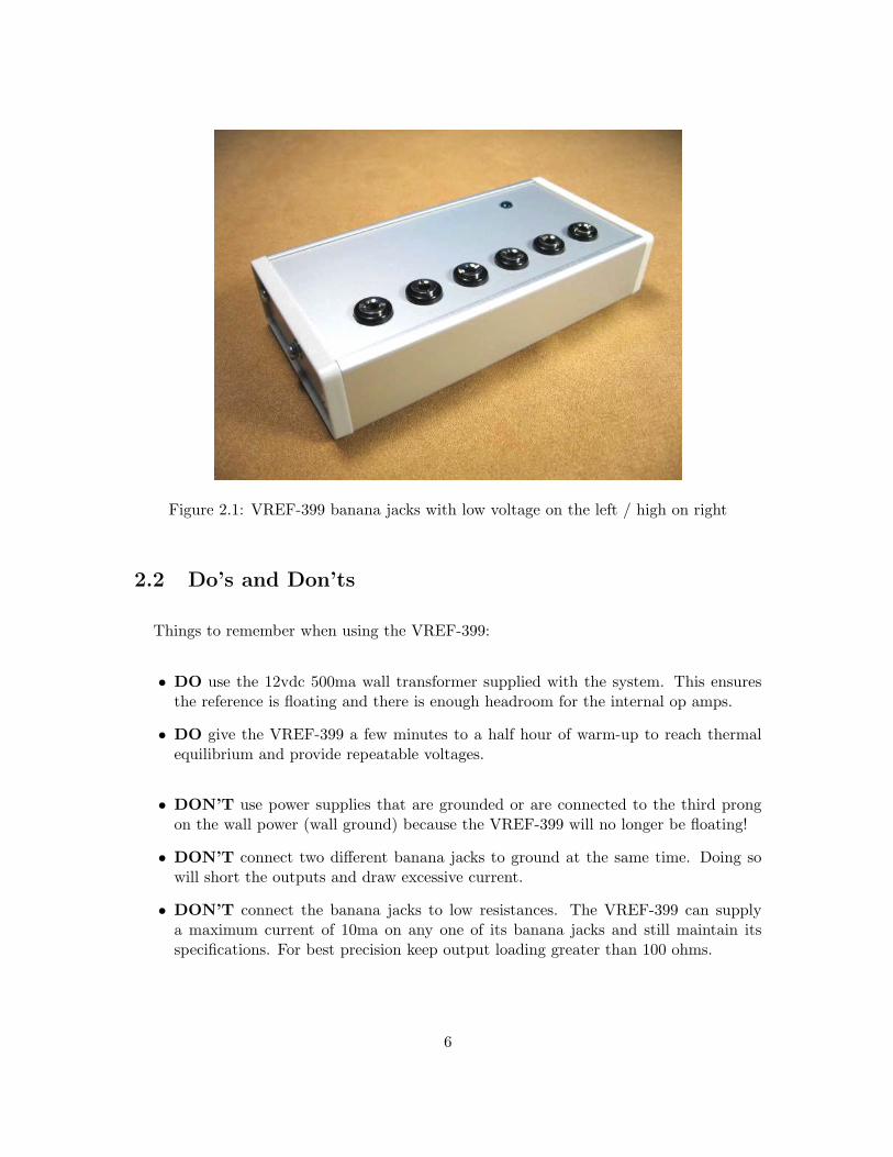
Figure 2.1: VREF-399 banana jacks with low voltage on the left / high on right
2.2 Do’s and Don’ts
Things to remember when using the VREF-399:
• DO use the 12vdc 500ma wall transformer supplied with the system. This ensuresthe reference is floating and there is enough headroom for the internal op amps.
• DO give the VREF-399 a few minutes to a half hour of warm-up to reach thermalequilibrium and provide repeatable voltages.
• DON’T use power supplies that are grounded or are connected to the third prongon the wall power (wall ground) because the VREF-399 will no longer be floating!
• DON’T connect two different banana jacks to ground at the same time. Doing sowill short the outputs and draw excessive current.
• DON’T connect the banana jacks to low resistances. The VREF-399 can supplya maximum current of 10ma on any one of its banana jacks and still maintain itsspecifications. For best precision keep output loading greater than 100 ohms.
6

Chapter 3
Theory of operation
3.1 Overall design
The core of the VREF-399 is comprised of a precision LM399 reference followed by a resistorladder to generate multiple voltages. The LM399 is a lab grade semiconductor referencewith a nominal 7 volt output, and is generally thought of as one of the best semiconductorreferences available. Its heater stabilized buried zener design guarantees the same voltagefrom one power on cycle to the next. While other semiconductor reference technologiessuch as bandgap references offer lower power consumption, they cannot match the LM399for repeatable performance and stability without hysteresis.
Following the LM399 is a resistor ladder which generates the multiple core VREF-399outputs which are further op amp buffered for the top panel banana jacks. The design firstreduces the LM399 output to 5 volts, and this is applied to a ladder of 5 equal resistorsto generate the 1 volt increments. Precision metal thin film resistors are used, with theessential circuit shown in Figure 3.1 on the following page. The dark arrowheads representeach output buffer and banana jack, and (V 1 . . . V 5) are the voltages between adjacentpairs of jacks.
Note the circuit fragment does not show any ground connection. The VREF-399 is floatingand can be reference to any ground desired. Any single one of the banana jacks canbe connected to your system ground, and then the remaining jacks will be distributedpositive and negative from that ground referenced point. This allows for very flexibleusage depending on the application. The op amp output buffering can supply 10ma perjack, isolating the core resistor ladder from user applications.
The design does not include any trim pots that could compromise thermal or long termstability. The concept is to accept any initial tolerances, record the outputs, and then tohave their values be the same from one power on cycle to next in any thermal environment.The advantages of this repeatability make avoiding the uncertainty of trim pots worth not
7

being trimmed to exactly 1 volt increments. A calibration tag is included with each systemreporting the banana jack voltages at the time of production. The initial tolerances andthe deviations from 1 volt increments are discussed in the next section.
Figure 3.1: VREF-399 output voltages
3.2 Operating tolerances
Although the core LM399 reference is extremely stable with respect to temperature andtime, its initial voltage tolerance is accurate only to within 5% across different parts. Thismeans the 5 volts shown across the resistor ladder in the circuit fragment above may varyfrom 4.75 to 5.25 volts depending on the LM399 in your unit. Any given VREF-399 willhave a voltage somewhere in this range between its highest and lowest banana jack thatwill not change with time or temperature.
Since the resistors in the ladder all have the same value, this also means the initial 5%LM399 uncertainty will result in 0.95 to 1.05 volts between any pair of adjacent bananajacks. This 5% initial overall tolerance is reported as Vjacks in the Specifications table, andis the primary contribution to deviation from exactly 1 volt increments between the jacks.
A much smaller deviation from 1 volt increments is contributed by the tolerances of theresistor ladder itself. Precision resistors with 0.05% initial tolerance are used. This means
8

the voltage between one adjacent pair of jacks to the next will be the same to within 0.05%.For example, if the LM399 voltage across the resistor ladder was 5 volts, then the nominalincrements between the jacks would be exactly 1 volt assuming perfect resistors. Resistortolerances would affect this value from one adjacent pair of jacks to the next to be between0.9995 and 1.0005 volts.
Once you determine the voltage between one pair of jacks, the value between other adjacentpairs will deviate by at most 0.05% = 500 ppm or 500 microvolts. This variation in voltagefrom one adjacent pair of jacks to the next is reported as ∆Vjacks in the Specificationstable. The exact voltages for a particular VREF-399 are reported on the calibration tag.
9
Chapter 4
Calibration
4.1 Production calibration
The VREF-399 is calibrated at the time of manufacturing. The calibration procedure is asfollows:
• An HP34401A 6 digit voltmeter is used for voltage measurement• The VREF-399 is powered from a 12v 500ma wall transformer (110vac/60Hz)• Both the VREF-399 and HP34401A are given a one hour warm up period• Voltage measurements are then taken referenced from the lowest banana jack• The same measurements are taken with the HP34401A voltmeter leads reversed• Measurements are repeated three times at one hour intervals• Results are averaged and a calibration tag is then included with the system
No other record of the calibration is provided with the system. If you loose your calibrationtag, follow steps similar to the above to recalibrate the system. You may also wish to writeout custom tags for particular applications, measuring the voltages with respect to variousjacks grounded. Blank tags are on the following page. Symmetric Research also attemptsto keep calibration information for shipped systems on record. Contact us and we may beable to help.
10
4.2 Calibration tags
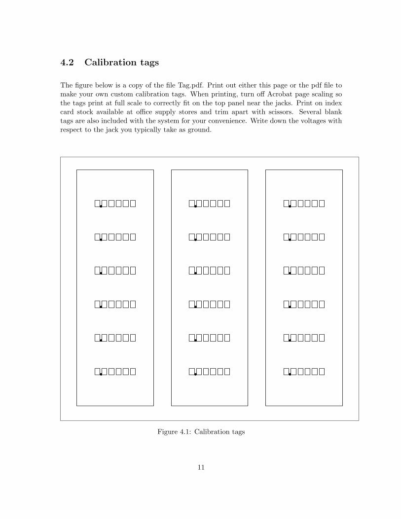
The figure below is a copy of the file Tag.pdf. Print out either this page or the pdf file tomake your own custom calibration tags. When printing, turn off Acrobat page scaling sothe tags print at full scale to correctly fit on the top panel near the jacks. Print on indexcard stock available at office supply stores and trim apart with scissors. Several blanktags are also included with the system for your convenience. Write down the voltages withrespect to the jack you typically take as ground.
Figure 4.1: Calibration tags
11

Chapter 5
Specifications
The table on the following page lists the leading VREF-399 specifications. Several of theperformance parameters are also discussed in the Theory of operation chapter. A few ofthe primary analog components used in the design are listed in the small table below.Component specification sheets are also included with the distribution CDROM.
Voltage reference = LM399H (National Semiconductor 5%)
Resistor ladder = RG1608N-1.0K-W-T1 (Susumu RG 0.05%)
Output opamps = OPA2277UA (Texas Instruments)
12

5.1 Specifications table
VREF-399 Specs
Parameter Comment Min Typ Max Units
Reference:
Vjacks 0.95 1 1.05 V
∆Vjacks variation one pair to next 0.05 %
Noise floor short term 5 µV
LM399 thermal stability long term 0.3 2 ppm per ◦C
R ladder thermal stability long term 10 ppm per ◦C
Output characteristics:
Output current (1) maximum 10 mA
Voltage drop 10ma, 100 ohm load 20 µV
Capacitive loading without oscillation 10 µF
Power supply:
Voltage (2) 14.7 17 30 Vdc
Current initial turn on 140 200 mA
Current (3) operating 60 mA
Warm-up time 0.5 hour
General:
Temp range 0 70 ◦C
Dimensions 2.5 x 5 inches
Figure 5.1: VREF-399 specifications table
(1) If more than 10ma is drawn from a banana jack, the output voltage may begin to drop and no longerremain constant, falling out of spec. Outputs are short circuit protected with current limiting at approxi-mately 35ma.
(2) Use only wall transformers that are floating and NOT connected to ground via the third wall prong asthis would compromise the floating nature of the VREF-399. Also note the 12vdc 500ma unregulated walltransformer supplied with the system will normally provide 17 volts when loaded with the normal 60maoperating current drain of the VREF-399.
(3) Normal power supply current is achieved about 2 minutes after the device is turned on. The LM399heater normally consumes around 30mA and maintains a temperature of 90◦C, almost the temp of boilingwater. At lower ambient temps the LM399 heater will require more power to maintain 90◦C, while at higherambient temps it will require less.
13

5.2 Short term noise
Work underway . . .
short term noise plot
Figure 5.2: VREF-399 short term noise
14

5.3 Long term noise
Work underway . . .
long term noise plot
Figure 5.3: VREF-399 long term noise
15

5.4 Thermal response
Work underway . . .
thermal response plot
Figure 5.4: VREF-399 thermal response
16

Chapter 6
Circuit Diagrams
FREE WEB VERSION - PARTIAL CIRCUIT DIAGRAMS
This free web copy of the User Manual includes only the Circuit Overview and connectorassignments. Complete circuit diagrams are provided only with purchase of the product.Install the CDROM that came with the product shipment for the full User Manual withcomplete diagrams. Customers who need an update or have lost their original CDROMmay obtain copies of the full User Manual by emailing Symmetric Research.
Use the Adobe Acrobat reader View/Rotate View/Clockwise command to present thediagrams horizontally on the screen.
Circuit Overview . . . . . . . . . . . . . . . . . . . . . . . . . . . . . . . . . . . . . . . . . . . . . . . . . . . . . . . . . . . . 18Banana jacks . . . . . . . . . . . . . . . . . . . . . . . . . . . . . . . . . . . . . . . . . . . . . . . . . . . . . . . . . . . . . . . . 19
17

A A
B B
C C
D D
E E
44
33
22
11
SR V
REF-
399
BLOC
K DI
AGRA
M OV
ERVI
EW
OUTP
UT B
UFFE
RS
SCHE
MATI
C PA
GES
3-5
(200
)
LOW
NOIS
E OP
A227
7 BU
FFER
SOU
TPUT
S IN
1 V
OLT
INCR
EMEN
TSLM
399
WITH
HEA
TER
(100
)
SCHE
MATI
C PA
GE 2
PREC
ISIO
N RE
FERE
NCE
(300
)
BANA
NA J
ACK
FOR
EACH
OUT
PUT
6 OU
TPUT
S AV
AILA
BLE
OUTP
UT C
ONNE
CTOR
S
FLOA
TING
OUT
PUTS
SCHE
MATI
C PA
GE 6
SERI
AL N
UMBE
R AN
D CA
LIBR
ATIO
N ST
ORAG
E
SCHE
MATI
C PA
GE 1
0
(400
)
EEPR
OM
2.1m
m PO
WER
CONN
ECTO
R
SCHE
MATI
C PA
GES
7-9
POWE
R SU
PPLY
(900
)
12 V
DC 5
00ma
FLO
ATIN
G WA
LL T
RANS
FORM
ER R
EQUI
RED
LINE
AR R
EGUL
ATIO
N FO
R LO
W NO
ISE
FACT
ORY
USE
ONLY
VR
EF
-399
.DS
N, (
c) S
ymm
etric
Res
earc
h, 2
007
C
01 O
VE
RV
IEW
A
110
Wed
nesd
ay, N
ovem
ber 0
7, 2
007
Titl
e
Siz
eD
ocum
ent N
umbe
rR
ev
Dat
e:S
heet
of
18

A A
B B
C C
D D
E E
44
33
22
11
REFE
RENC
E OU
TPUT
BAN
ANA
JACK
S
ALL
OUTP
UTS
FLOA
TING
FROM
OUT
PUT
BUFF
ERS
VR
EF
-399
.DS
N, (
c) S
ymm
etric
Res
earc
h, 2
007
C
06 A
NA
OU
TP
UT
CO
NN
EC
TO
R
A
610
Wed
nesd
ay, N
ovem
ber 0
7, 2
007
Titl
e
Siz
eD
ocum
ent N
umbe
rR
ev
Dat
e:S
heet
of
VB
RE
F5
VB
RE
F4
VB
RE
F2
VB
RE
F1
VB
RE
F0
VB
RE
F3
VB
RE
F0
VB
RE
F1
VB
RE
F2
VB
RE
F3
VB
RE
F4
VB
RE
F5J3
05B
AN
AN
A J
AC
K1
J304
BA
NA
NA
JA
CK
1
J303
BA
NA
NA
JA
CK
1
J302
BA
NA
NA
JA
CK
1
J301
BA
NA
NA
JA
CK
1
J300
BA
NA
NA
JA
CK
1
J311
BR
AC
KE
T F
RO
NT
PA
NE
L1
J310
BR
AC
KE
T B
AC
K P
AN
EL
1
19

Chapter 7
Examples and Experiments
The following are some examples of how to use the VREF-399:
. Connector options ways to connect to the banana jacks
. Measuring the outputs using a Fluke meter to measure the reference
. Negative voltages how to use the floating outputs
. Potentiometer usage providing excitation voltages for sensors
. Differential applications noise reduction with differential signals
. A/D converter calibration calibrating differential A/D inputs
20

7.1 Connector options
There are several ways to use the VREF-399 banana jacks. The best one to use depends onthe equipment you are working with. The following photos show some of the possibilities.
Figure 7.1: VREF-399 with banana plugs installed
Figure 7.2: VREF-399 with alligator leads installed
21
7.2 Measuring the outputs
The six constant voltages on the banana jacks range from 0 to 5 volts in increments ofapproximately 1 volt. With no trim pots, the system has excellent long term stability. Butin return, the output voltages are not trimmed to integral values such as 3.00000 volts andmay have values such as 2.98786 volts. A measurement of the voltages is done at the timeof production, and the results are printed out on a calibration tag.
You can repeat the calibration yourself if you have access to a precision voltmeter. Meterssuch as the Fluke 170 series are also acceptable for many applications. Uncertainty in theinitial absolute voltage at any banana jack is a different issue than the long term stability.With the VREF-399 as its source, an A/D converter should return the same count resultseach time a calibration is performed.
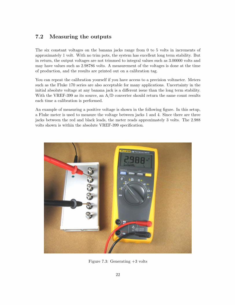
An example of measuring a positive voltage is shown in the following figure. In this setup,a Fluke meter is used to measure the voltage between jacks 1 and 4. Since there are threejacks between the red and black leads, the meter reads approximately 3 volts. The 2.988volts shown is within the absolute VREF-399 specification.
Figure 7.3: Generating +3 volts
22

7.3 Negative voltages
Besides positive voltages, the VREF-399 can also generate negative voltages. Because thereference is floating and not tied to a system ground, any of the jacks can be taken asground.
The figure below shows the setup for providing a constant minus 3 volts. Even though theFluke meter is floating, the jack with black test lead could be connected to your systemground because the VREF-399 is not ground referenced either. With the red test lead ona lower jack a negative voltage is supplied. You can see the meter does not read exactlyminus three volts, but is within the accuracy specification. What you will find is exactlythe same -2.988 voltage is returned from one power on to the next.
Figure 7.4: Generating -3 volts
23

7.4 Potentiometer usage
The VREF-399 can be used with a 10 turn potentiometer to generate small increments involtage for testing at low voltages.
Work underway . . .
24

7.5 Differential applications
The VREF-399 is perfect for use with systems having differential inputs. Differential con-nections are very effective techniques for dealing with ground loop currents and noise.
Work underway . . .
25

7.6 A/D converter calibration
The physical quantity intrinsically measured by most A/D systems is voltage, where acorresponding digital count value is returned to the computer. Low input voltages returna low count value, and as the voltage grows so does the count value.
The relationship between an input voltage and the output counts is referred to as the DCCalibration of the A/D system, and is commonly modeled by a straight line with a slopeand offset. Determining the slope and offset of this line is the goal of calibration. Deviationsfrom a straight line characterize the nonlinearity of the system.
The VREF-399 can be used to perform A/D calibration by supplying several constantvoltages. For each voltage, acquire some data and then use the (voltage,count) pairs to fitthe best possible straight line. The resulting line will relate any particular output count toan input voltage.
Because the VREF-399 is an independent stand alone reference, it provides an absolutecalibration standard. With its buried zener design and heated thermal stabilization, theLM399 reference is considered one of the best semiconductor references available and willprovide repeatable measurements.
Work underway . . .
26

Chapter 8
Frequently Asked Questions
The following FAQ may help if you have general questions about the VREF-399.
What is a buried zener ?
Common zener diodes have their junction exposed to the surface of the siliconsubstrate. For such diodes, surface currents and oxidation compromise theshort term noise and long term stability of the diode. Buried zeners place thejunction below the substrate surface to avoid these effects. The technique workswell, with buried zeners recognized as one of the best semiconductor referencetechnologies available. The performance of a buried zener is further enhancedwhen thermally stabilized as with the LM399.
What kind of power supplies can I use for the VREF-399 ?
Be sure to use a standard unregulated wall transformer that is connected to wallpower with only two prongs as is supplied with the system. If you use a powersupply that is grounded to the third prong on the wall socket, or other form ofsystem ground, then the VREF-399 will be referenced to that ground and nolonger be floating.
Can I really ground any of the six banana jacks ?
Yes. You can connect any one of the six banana jacks to your system ground.The remaining jacks will then be at approximately 1 volt increments positiveand negative from the grounded jack. Do not ground more than one jack at atime. Doing so shorts jacks together drawing excessive current.
27

I have lost my calibration tag, what can I do ?
The best approach is to re-measure the voltage at each jack and write a newcalibration tag. See the Calibration tags section for blank tags. SR attemptsto maintain calibration records. Contact us by email if you need help. Theproduct serial number will be required.
What affects voltage accuracy ?
For precise measurements at microvolt levels, the main culprit compromisingaccuracy is voltage drops due to wiring. The feedback point for the op ampsdriving the jacks is placed exactly at the banana jacks.
Drawing 10ma from a jack will not effect the voltage at the jack to withinspecifications. However, if you connect to the jacks through long wires, andthen draw 10ma, the voltages at the ends of your wires will be off by the amountdictated by Ohm’s law. In those cases, keep your wires short and draw as littlecurrent as possible.
Typically 24 gauge stranded wire has a resistance of approximately 20 ohmsper 1000 feet. So, a one foot length with a resistance of 0.02 ohms and a10ma current would have a V = IR = 0.0002 voltage drop. Depending on theapplication, this may represent a significant error. Clearly with 100 feet of wirethe error becomes even larger.
For ease of use, the VREF-399 does not have separate Kelvin connections. TheKelvin points are at the banana jacks, and voltages are maintained at thosepoints with the specified accuracy.
Besides voltage drops due to wiring, sometimes thermocouple effects betweenmetal junctions is a concern. One way to address such problems is to makedifferential measurements and ensure the same number of thermocouples occurin each side of the differential pair. See the Differential applications section.
Are the voltage increments between jacks exactly 1 volt ?
No. They are only approximately one volt apart, where approximately meansto within the specified absolute accuracy.
To avoid problems with long term drift, the VREF-399 does not have any trimpots. The goal of the device is to provide the same voltages at the bananajacks from one power on to the next over long periods of time. Use the produc-tion calibration info supplied with the system to scale A/D counts and similarmeasurements into exact counts/volt etc.
28
Chapter 9
Extra supplies
Extra basic supplies such as cable and connectors may be required depending on theVREF-399 application. SR can often provide such supplies on request, however manycustomers may want to purchase such parts directly from suppliers themselves. This chap-ter lists a few typical parts and vendors. The list is only representative with many othersuppliers providing equally good products.
DigiKeywww.digikey.com1(800)344-4539
Mouser Electronicswww.mouser.com1(800)346-6873
JDR Microdeviceswww.jdr.com1(800)538-5000
Abbreviations used below:
MFG = ManufacturerDK = DigiKeyMO = MouserJDR = JDR Microdevices
29
9.1 Small parts for cables etc
Some of the more common parts used in VREF-399 applications are as follows:
Alligator clips
MFG part number = Mueller BU-30DK part number = 314-1010-ND
MFG part number = Silvertronic 501793MO part number = 835-501793
The Mueller BU-30 clip has a good spring and strong teeth. The connection is wire crimp,which should also be soldered for low resistance. Making cables with these clips requiresskill, but they result in inexpensive connections of good quality that are easy to use. TheSilvertronic part is equivalent to the Mueller.
Johnson banana plugs
MFG part number = Johnson (Emerson) 108-753-001DK part number = J149-NDMO part number = 530-108-0753-1
These uninsulated banana plugs have a 6-32 screw in the end. When plugged into VREF-399banana jacks, they provide screw terminal connections.
Solder terminal lugs for Johnson banana plugs
MFG part number = Keystone 7329DK part number = 7329K-NDMO part number = 534-7329
The Keystone solder lugs are useful for making screw terminal connections to the Johnsonbanana plugs. It is also easy to clip alligators onto these lugs when they have no wire solderedon. The lugs listed above are flat. Lugs with internal tooth lock washer holes are also availablefor even more secure connection.
Pomona test leads
MFG part number = Pomona 5519ADK part number = 501-1004-NDMO part number = 565-5519A
To use these test leads with the VREF-399 you must trim or cut away the banana pluginsulating shroud. Do this with a utility knife or razor blade carefully cutting away theplastic shroud.
30

Twisted pair shielded cable
MFG part number = Belden 9501MO part number = 566-9501-100
Twisted pair provides reasonable powerline noise immunity. This Belden cable also has a foilshield and is jacketed. There are a large number of cable types available. The above is onlyone example.
Potentiometers, 10 turn, 10K ohm
MFG part number = Vishay (Sfernice) 53411103MO part number = 594-53411103
MFG part number = Bourns 3540 seriesDK part number = 3540S-1-103-ND
A 10 turn pot is a simple and reasonably accurate sensor to use when testing the VREF-399.There are many manufacturers of 10 turn pots. A 10K ohm unit will not draw excessivecurrent from the VREF output.
Wall transformers
MFG part number = XiconMO part number = 412-112054 (12vdc 500ma 2.1mm plug, 110vac input ** US)
Don’t use switching regulated wall transformers with the VREF-399. They will introduceconsiderable high frequency noise into the system. Use only floating unregulated linear walltransformer. Be sure to use a 12 volt 500ma unit. 9 volt units are not acceptable. Do notdaisy chain the wall transformer to other equipment creating unexpected ground connections.
2.1mm power plug
MFG part number = CUI Inc PP3-002ADK part number = CP3-1000A
MFG part number = KobiconnMO part number = 1710-2131
These are discrete wire power plugs suitable for soldering wires to. They are useful forconnecting batteries and other custom power sources to the VREF-399. Use these instead ofchopping the plug off your wall transformer.
31

Batteries, 12 volt lead acid
MFG part number = BB Battery BP1.2-12-T1 (12v 1.2Ah)DK part number = 522-1007-ND
MFG part number = Power Sonic (12v 1.4Ah)MO part number = 547-PS-1212
These are small lead acid batteries. Running the VREF-399 from batteries may be of interestfor the ultimate in a floating reference. A 1.2 Ah battery would have enough power to run theVREF-399 continuously for approximately 1.2/0.060 = 20 hours. Enough time to do somereasonable work. Lead acid batteries are rechargeable.
32

Getting Technical Help
Answers to many general questions as well as resources such as application notes can befound on our web site. If you have additional technical questions, please email us:
General product information: www.symres.comSR technical help email address: [email protected]
33

Trees are greenYakima, Washington, May 2006
VREF-399 User Manual
Copyright c©, Symmetric Research, 2006, 2010
This material can only be reproduced in whole or part with the written permission ofSymmetric Research
No guarantee of suitability for any application is made with this documentAll liabilities are the responsibility of the user
Email: [email protected] Web: www.symres.com
34