Embed Size (px)
Citation preview
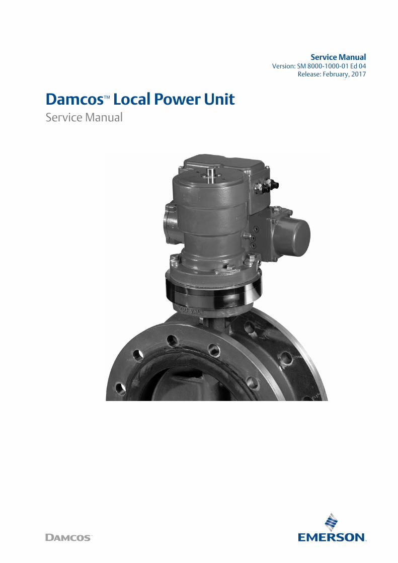
Service ManualVersion: SM 8000-1000-01 Ed 04
Release: February, 2017
Damcos™ Local Power UnitService Manual
The content of this publication are presented for information purposes only, and while effort has been made to ensure their accuracy, they are not to be construedas warranties or guarantees, expressed or implied, regarding the products or services described herein or their use or applicability. All sales are governed by ourterms and conditions, which are available upon request. We reserve the right to modify or improve the designs or specifications of our products at any time with-out notice. Damcos A/S accepts no responsibility for any errors that may appear in this publication. As each system may be configured for each delivery, the content and illustrations in this manual may differ from your system.
Copyright © Damcos A/S, 2017Service Manual for LPU in English
Damcos LPU: Table of Contents Service ManualFebruary 2017 SM 8000-100-01 Ed 04
Table of ContentsAbbreviation and Denomination . . . . . . . . . . . . . . . . . . . . . . . . . . . . . . . . . 7
Safety . . . . . . . . . . . . . . . . . . . . . . . . . . . . . . . . . . . . . . . . . . . . . . . . . . . . . . . . 9Warning Levels Used in Manuals . . . . . . . . . . . . . . . . . . . . . . . . . . . . . . . . . . . . . 10
General Service Instructions for LPU . . . . . . . . . . . . . . . . . . . . . . . . . . . . . 13General Considerations . . . . . . . . . . . . . . . . . . . . . . . . . . . . . . . . . . . . . . . . . . . . . 14LPU and Optional Equipment . . . . . . . . . . . . . . . . . . . . . . . . . . . . . . . . . . . . . . . . 16
LPU-S Overview . . . . . . . . . . . . . . . . . . . . . . . . . . . . . . . . . . . . . . . . . . . . . . 19Overview LPU-S . . . . . . . . . . . . . . . . . . . . . . . . . . . . . . . . . . . . . . . . . . . . . . . . . . . . 20
LPU-S-Ex Overview . . . . . . . . . . . . . . . . . . . . . . . . . . . . . . . . . . . . . . . . . . . . 23Overview LPU-S-Ex . . . . . . . . . . . . . . . . . . . . . . . . . . . . . . . . . . . . . . . . . . . . . . . . . 24
LPU-S-Ex-ia Overview . . . . . . . . . . . . . . . . . . . . . . . . . . . . . . . . . . . . . . . . . . 27Overview LPU-S-Ex-ia . . . . . . . . . . . . . . . . . . . . . . . . . . . . . . . . . . . . . . . . . . . . . . . 28
LPU-D Overview . . . . . . . . . . . . . . . . . . . . . . . . . . . . . . . . . . . . . . . . . . . . . . 31Overview LPU-D. . . . . . . . . . . . . . . . . . . . . . . . . . . . . . . . . . . . . . . . . . . . . . . . . . . . 32
LPU-D-Ex Overview . . . . . . . . . . . . . . . . . . . . . . . . . . . . . . . . . . . . . . . . . . . 35Overview LPU-D-Ex . . . . . . . . . . . . . . . . . . . . . . . . . . . . . . . . . . . . . . . . . . . . . . . . 36
LPU-D-Ex-ia Overview . . . . . . . . . . . . . . . . . . . . . . . . . . . . . . . . . . . . . . . . . 39Overview LPU-D-Ex-ia . . . . . . . . . . . . . . . . . . . . . . . . . . . . . . . . . . . . . . . . . . . . . . 40
Troubleshooting Guide LPU . . . . . . . . . . . . . . . . . . . . . . . . . . . . . . . . . . . . 43Fault Finding List LPU . . . . . . . . . . . . . . . . . . . . . . . . . . . . . . . . . . . . . . . . . . . . . . . 45LPU-S frequently restarting in open position . . . . . . . . . . . . . . . . . . . . . . . . . . . 47Motor not running and is hot . . . . . . . . . . . . . . . . . . . . . . . . . . . . . . . . . . . . . . . . 49Motor not running and is Cold . . . . . . . . . . . . . . . . . . . . . . . . . . . . . . . . . . . . . . . 49Motor not stopping . . . . . . . . . . . . . . . . . . . . . . . . . . . . . . . . . . . . . . . . . . . . . . . . 50Pump rendering too low (or no) pressure in one or both directions . . . . . . . 51Solenoid valve not working . . . . . . . . . . . . . . . . . . . . . . . . . . . . . . . . . . . . . . . . . . 52Actuator only running in one direction (the unit can either only open or only close) . . . . . . . . . . . . . . . . . . . . . . . . . . . 53Noise from pump, but only at low pressure . . . . . . . . . . . . . . . . . . . . . . . . . . . . 54
3
Service Manual Damcos LPU: Table of ContentsSM 8000-100-01 Ed 04 February 2017
Noise from pump, but only at high pressure . . . . . . . . . . . . . . . . . . . . . . . . . . . 55Noise from pump at both high and low pressure. . . . . . . . . . . . . . . . . . . . . . . . 55Motor running hot, LPU is operating normally . . . . . . . . . . . . . . . . . . . . . . . . . . 56LPU-D not maintaining pressure on actuator . . . . . . . . . . . . . . . . . . . . . . . . . . . 57Spring actuator only partly closing or not starting to close . . . . . . . . . . . . . . . 58Emergency operation by key giving oil spillage through breather valve . . . . 59Emergency operation by key not possible, hydraulically locked. . . . . . . . . . . 59Emergency operation by hand pump giving oil spillage through breather valve 59Emergency operation by hand pump not possible . . . . . . . . . . . . . . . . . . . . . . 60Pump not rendering sufficient oil at high pressure (“valve running too slowly”) 61Pump not rendering sufficient oil at low pressure (“valve running too slowly”) 61Motor running for a short time and stopsHigh pressure on the port to which oil is led . . . . . . . . . . . . . . . . . . . . . . . . . . . . 62Motor running for a short time and stops . . . . . . . . . . . . . . . . . . . . . . . . . . . . . . 62Motor ”diving” in RPM in end position . . . . . . . . . . . . . . . . . . . . . . . . . . . . . . . . 63Motor ”diving” in RPM as spring actuator opens . . . . . . . . . . . . . . . . . . . . . . . . 63Oil spillage, generally . . . . . . . . . . . . . . . . . . . . . . . . . . . . . . . . . . . . . . . . . . . . . . . 64Oil in electronic connection box . . . . . . . . . . . . . . . . . . . . . . . . . . . . . . . . . . . . . . 64Oil spillage from breather valve. . . . . . . . . . . . . . . . . . . . . . . . . . . . . . . . . . . . . . . 64Unit drawing too much current. . . . . . . . . . . . . . . . . . . . . . . . . . . . . . . . . . . . . . . 65Too little tank volume for operating actuator . . . . . . . . . . . . . . . . . . . . . . . . . . 66LPU cannot raise pressure after hand pump operation (but no problems after remote operation) . . . . . . . . . . . . . . . . . . . . . . . . . . . . . 67LPU leaking from bleeder valve when hand pump is mounted . . . . . . . . . . . . 68Spring actuator do not close by emergency hand pump operation . . . . . . . . 69LPU-Ex motor do not run . . . . . . . . . . . . . . . . . . . . . . . . . . . . . . . . . . . . . . . . . . . . 70LPU-Ex has to be bulkhead mounted because of too little space or zone 0 at ac-tuator . . . . . . . . . . . . . . . . . . . . . . . . . . . . . . . . . . . . . . . . . . . . . . . . . . . . . . . . . . . . . 71Position indicator errors . . . . . . . . . . . . . . . . . . . . . . . . . . . . . . . . . . . . . . . . . . . . . 72
Operating LPU-S 2 . . . . . . . . . . . . . . . . . . . . . . . . . . . . . . . . . . . . . . . . . . . . 73
Operating LPU-D 2a . . . . . . . . . . . . . . . . . . . . . . . . . . . . . . . . . . . . . . . . . . . 75
Emergency Operation of LPU V.2 . . . . . . . . . . . . . . . . . . . . . . . . . . . . . . . . 77
Speed adjustment for Actuator on LPU (v.2) . . . . . . . . . . . . . . . . . . . . . . 83
Pump pressure adjustment for LPU . . . . . . . . . . . . . . . . . . . . . . . . . . . . . . 85
4
Damcos LPU: Table of Contents Service ManualFebruary 2017 SM 8000-100-01 Ed 04
Refill of Oil in LPU . . . . . . . . . . . . . . . . . . . . . . . . . . . . . . . . . . . . . . . . . . . . . 87
Replace Pump in LPU . . . . . . . . . . . . . . . . . . . . . . . . . . . . . . . . . . . . . . . . . . 93
Replace DPCV in LPU . . . . . . . . . . . . . . . . . . . . . . . . . . . . . . . . . . . . . . . . . . 97
Replace release valve in LPU . . . . . . . . . . . . . . . . . . . . . . . . . . . . . . . . . . . . 99
Setup new P-net LPU circuit board . . . . . . . . . . . . . . . . . . . . . . . . . . . . . 101
Setup new P-net LPU circuit board in VIEW ver. 3.16 . . . . . . . . . . . . . . 103
Replace Printed Circuit Board . . . . . . . . . . . . . . . . . . . . . . . . . . . . . . . . . . 105
Replace Solenoid Valve in LPU-D . . . . . . . . . . . . . . . . . . . . . . . . . . . . . . . 107
Replace pressure switch . . . . . . . . . . . . . . . . . . . . . . . . . . . . . . . . . . . . . . 109
LPU Technical Data . . . . . . . . . . . . . . . . . . . . . . . . . . . . . . . . . . . . . . . . . . . 111Technical Data . . . . . . . . . . . . . . . . . . . . . . . . . . . . . . . . . . . . . . . . . . . . . . . . . . . . 113
LPU Power Control System . . . . . . . . . . . . . . . . . . . . . . . . . . . . . . . . . . . . 119LPU Power Control Description . . . . . . . . . . . . . . . . . . . . . . . . . . . . . . . . . . . . . 121Operation LPU-S . . . . . . . . . . . . . . . . . . . . . . . . . . . . . . . . . . . . . . . . . . . . . . . . . . 123Operating LPU-D . . . . . . . . . . . . . . . . . . . . . . . . . . . . . . . . . . . . . . . . . . . . . . . . . . 124LPU with LED Position Indicator . . . . . . . . . . . . . . . . . . . . . . . . . . . . . . . . . . . . . 125
LPU P-NET System . . . . . . . . . . . . . . . . . . . . . . . . . . . . . . . . . . . . . . . . . . . 129LPU P-Net Description . . . . . . . . . . . . . . . . . . . . . . . . . . . . . . . . . . . . . . . . . . . . . 131PCB Diagram for Local Control . . . . . . . . . . . . . . . . . . . . . . . . . . . . . . . . . . . . . . 132PCB Diagram for Stand Alone Unit. . . . . . . . . . . . . . . . . . . . . . . . . . . . . . . . . . . 133
Hydraulic Hand Pump . . . . . . . . . . . . . . . . . . . . . . . . . . . . . . . . . . . . . . . . 135Technical Data . . . . . . . . . . . . . . . . . . . . . . . . . . . . . . . . . . . . . . . . . . . . . . . . . . . . 137Hydraulic Diagram for Direct Mounted LPU Handpump . . . . . . . . . . . . . . . . 138Hydraulic Diagram for Bulkhead Mounted LPU Handpump . . . . . . . . . . . . . 139
Index . . . . . . . . . . . . . . . . . . . . . . . . . . . . . . . . . . . . . . . . . . . . . . . . . . . . . . . 141
5

Service Manual Damcos LPU: Table of ContentsSM 8000-100-01 Ed 04 February 2017
6
Damcos LPU: Abbreviation and Denomination Service ManualFebruary 2017 SM 8000-100-01 Ed 04
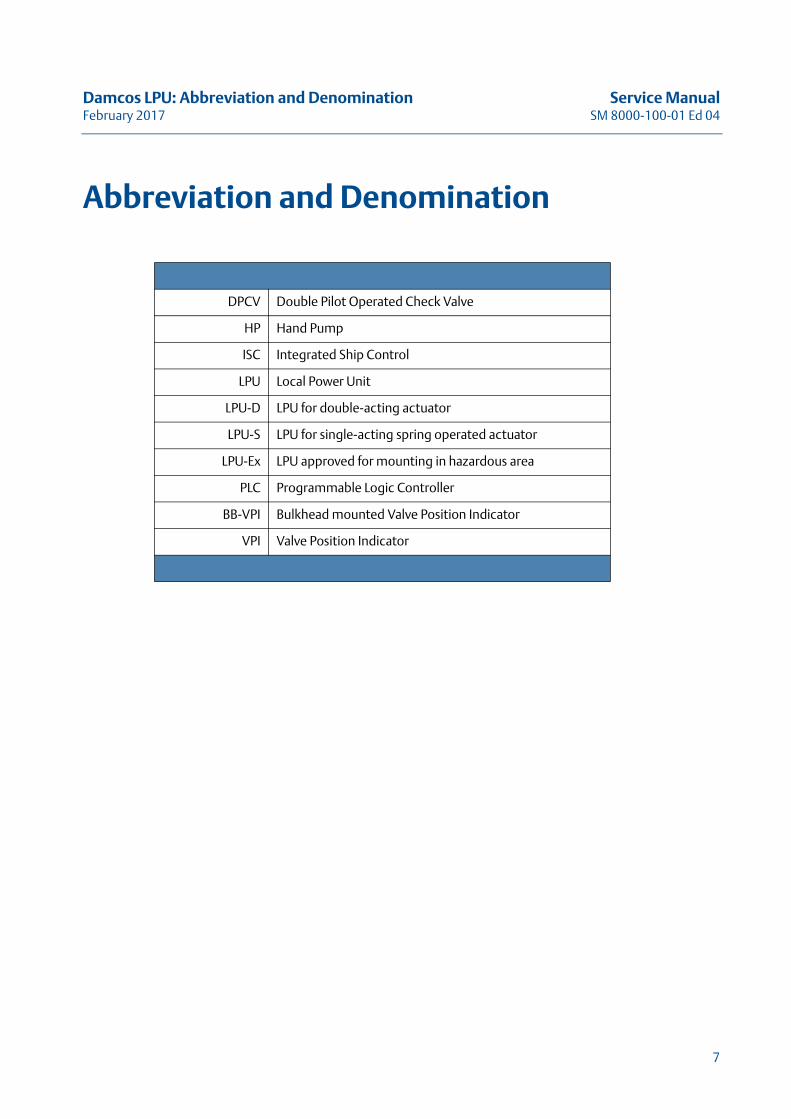
Abbreviation and Denomination
DPCV Double Pilot Operated Check Valve
HP Hand Pump
ISC Integrated Ship Control
LPU Local Power Unit
LPU-D LPU for double-acting actuator
LPU-S LPU for single-acting spring operated actuator
LPU-Ex LPU approved for mounting in hazardous area
PLC Programmable Logic Controller
BB-VPI Bulkhead mounted Valve Position Indicator
VPI Valve Position Indicator
7

Service Manual Damcos LPU: Abbreviation and DenominationSM 8000-100-01 Ed 04 February 2017
8
Damcos LPU: Safety Service ManualFebruary 2017 SM 8000-100-01 Ed 04
SafetyA description of issues concerning
personal safety when handling
DamcosTM VRC
9
Service Manual Damcos LPU: SafetySM 8000-100-01 Ed 04 February 2017
Warning Levels Used in ManualsThe following warning levels are used in the documentation of Damcos A/S for the safety of people and equipment.
Warning! Indicates a potentially hazardous situation which, if not avoided, could result in death or serious injury.
Caution! Indicates a potentially hazardous situation which, if not avoided, may result in prop-erty damage.
Note! Indicates important information regarding the product.
WarningsAll personnel that handles Damcos LPU shall take part of and understand the following information prior to handling the system. See warnings on next page.
10
Damcos LPU: Safety Service ManualFebruary 2017 SM 8000-100-01 Ed 04
11

Service Manual Damcos LPU: SafetySM 8000-100-01 Ed 04 February 2017
12
Damcos LPU: General Service Instructions for LPU Service ManualFebruary 2017 SM 8000-100-01 Ed 04
General Service Instructions for LPUThis Chapter Describes the General Requirements
and Service Recommendations for the LPU
13
Service Manual Damcos LPU: General Service Instructions for LPUSM 8000-100-01 Ed 04 February 2017
General ConsiderationsImportant notes on LPU equipment and systems:
• use original spare parts and tools • use lifting facilities and transport equipment• use handling instructions• electrical cables are only to be connected by qualified personnel
Note! Read Safety chapter before handling any equipment!
Bleeder valve positions on LPUIt is extremely important that bleeder valve position is correctly chosen when mounting LPU with actuator on pipe. Other positions are plugged when not used! This is normally done at installation.
Note! The choice of bleeder valve position is always selected at the highest point on LPU or actu-ator tank!
For KC/KF/KFR bleed valve on top of actuator has no connection to LPU tank and must always be present!
See next page for illustrated examples.
14
Damcos LPU: General Service Instructions for LPU Service ManualFebruary 2017 SM 8000-100-01 Ed 04
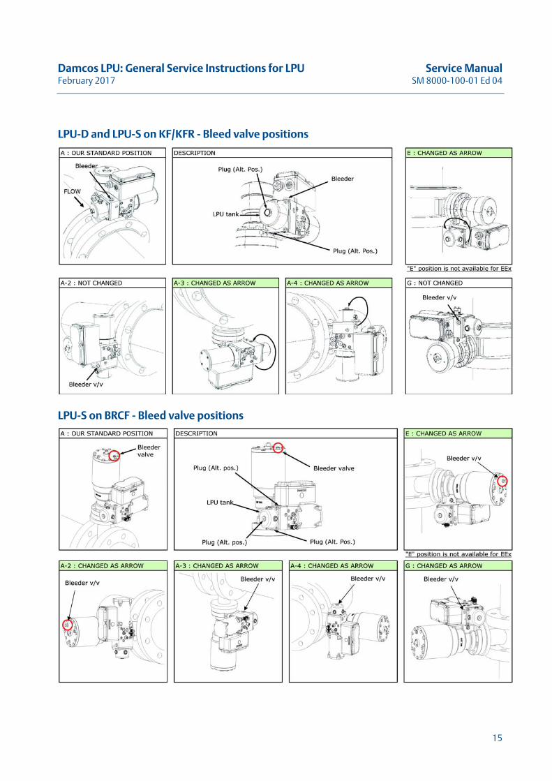
LPU-D and LPU-S on KF/KFR - Bleed valve positions
LPU-S on BRCF - Bleed valve positions
15
Service Manual Damcos LPU: General Service Instructions for LPUSM 8000-100-01 Ed 04 February 2017
LPU and Optional EquipmentThe LPU can be equipped with additional equipment, such as switches, indicators etc. Further more the LPU can be bulkhead mounted, mounted with blocks or otherwise mounted in respect to cus-tomer requirements and system. Always check your specific system drawings and documents for correct information. This manual is a guide on how to perform the service parts of your system. For further information please contact Emerson service engineer or appointed agent.
DescriptionThe LPU offers installation in both safe and hazardous area in two basic versions:
• LPU-S (fail safe) for single acting actuator• LPU-D (fail set) for double acting actuator
Depending on safety zone requirements the LPU’s can be of Ex or Ex-ia, designed to meet the requirements for mounting in hazardous areas. Be sure to use the designated equipment and spare parts when performing service on your system.The LPU system is designed to be controlled by two electrically different types of controls:
• Power controlled• P-NET® bus controlled
The LPU can also be used as a stand-alone system.
LPU with an LED Position IndicatorLPU (except the Ex version) with an IP 68 LED indicator, showing clear RED or GREEN light when the valve is CLOSED respectively OPEN is available in Power controlled and P-NET controlled LPU systems. This may especially be useful if LPU is operated from a local hand pump, were the LPU is mounted in a distance so the indication of the actuator is not visible. The LED must be supplied with 24 VDC.
LPU MountingThe LPU can be mounted in the following ways:
• Direct mounting on BRC 250 - 16000, BRCF 250 - 16000, KC 65 - 400 and KF 65-250.• Mounting on BRC 052, 072 and 092 is via inter-mediate block and with external position indica-
tion cable.• Mounting on BRCF Fail Open and KF Fail Open is via special intermediate block.• Mounting on BRC 125 and BRCF 125 has to be bulkhead mounted or supported otherwise.• LPU may be bulk-head mounted via a standard B-block. - It is possible to use a B-block with inte-
grated VPI, (please see illustration). No external indication cable.When decided on mounting method the pipe dimensions has to be considered as well.
16
Damcos LPU: General Service Instructions for LPU Service ManualFebruary 2017 SM 8000-100-01 Ed 04
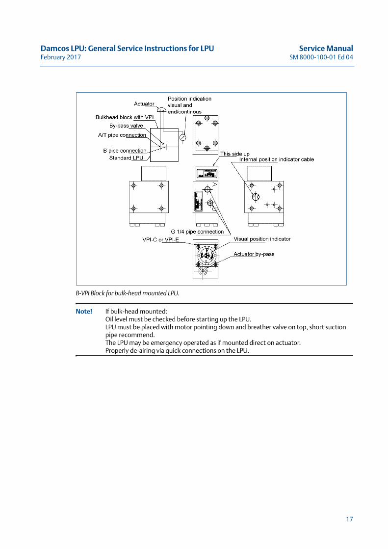
B-VPI Block for bulk-head mounted LPU.
Note! If bulk-head mounted:Oil level must be checked before starting up the LPU. LPU must be placed with motor pointing down and breather valve on top, short suction pipe recommend.The LPU may be emergency operated as if mounted direct on actuator.Properly de-airing via quick connections on the LPU.
17
Service Manual Damcos LPU: General Service Instructions for LPUSM 8000-100-01 Ed 04 February 2017
18
Damcos LPU: LPU-S Overview Service ManualFebruary 2017 SM 8000-100-01 Ed 04
LPU-S OverviewThis Chapter Describes the LPU-S with
Overview and Handling Instructions
19
Service Manual Damcos LPU: LPU-S OverviewSM 8000-100-01 Ed 04 February 2017
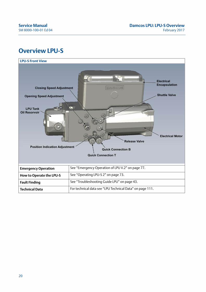
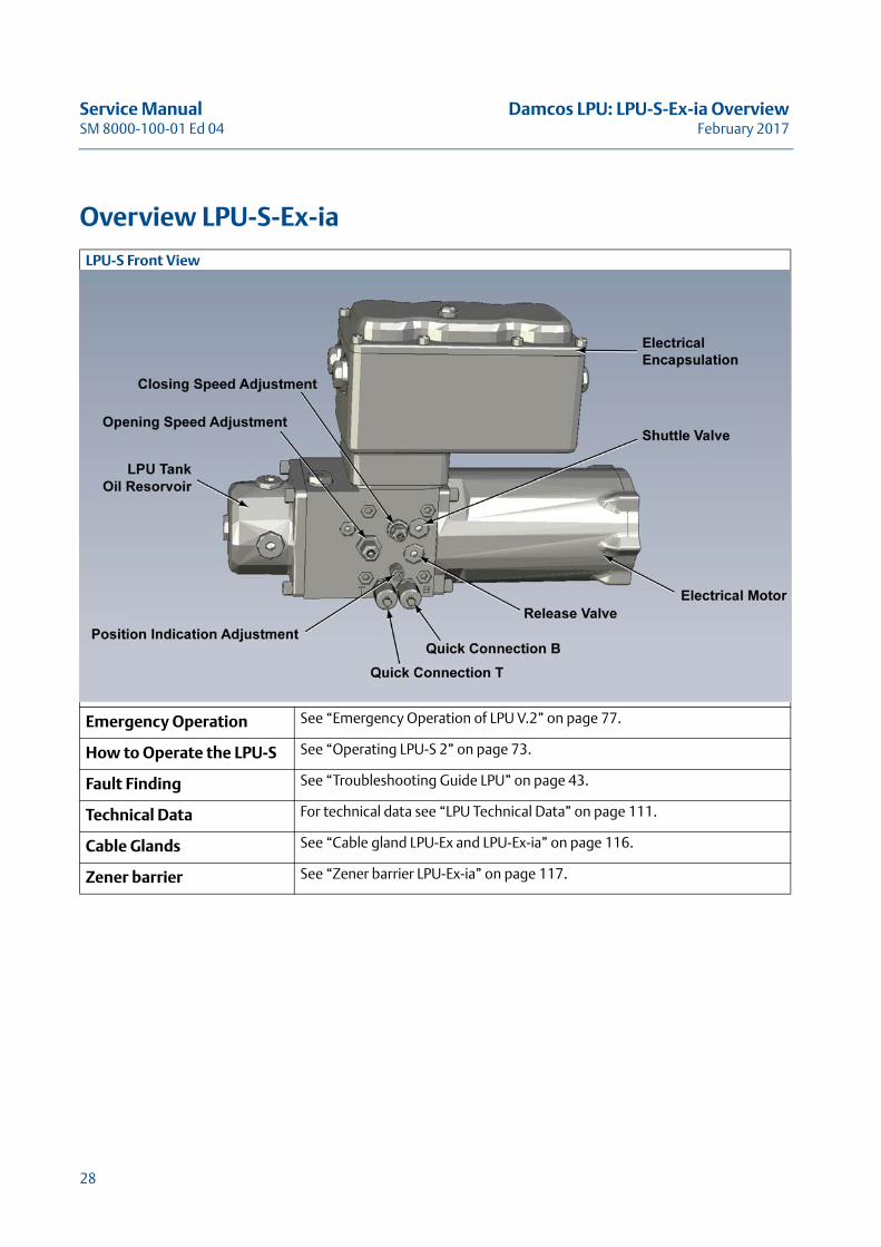
Overview LPU-S
LPU-S Front View
Emergency Operation See “Emergency Operation of LPU V.2” on page 77.
How to Operate the LPU-S See “Operating LPU-S 2” on page 73.
Fault Finding See “Troubleshooting Guide LPU” on page 43.
Technical Data For technical data see “LPU Technical Data” on page 111.
20
Damcos LPU: LPU-S Overview Service ManualFebruary 2017 SM 8000-100-01 Ed 04
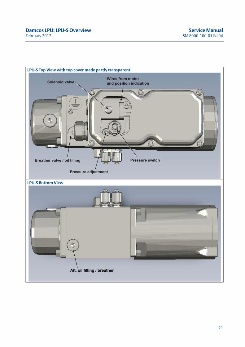
LPU-S Top View with top cover made partly transparent.
LPU-S Bottom View
21

Service Manual Damcos LPU: LPU-S OverviewSM 8000-100-01 Ed 04 February 2017
22
Damcos LPU: LPU-S-Ex Overview Service ManualFebruary 2017 SM 8000-100-01 Ed 04
LPU-S-Ex OverviewThis Chapter Describes the LPU-S-Ex with
Overview and Handling Instructions
23
Service Manual Damcos LPU: LPU-S-Ex OverviewSM 8000-100-01 Ed 04 February 2017
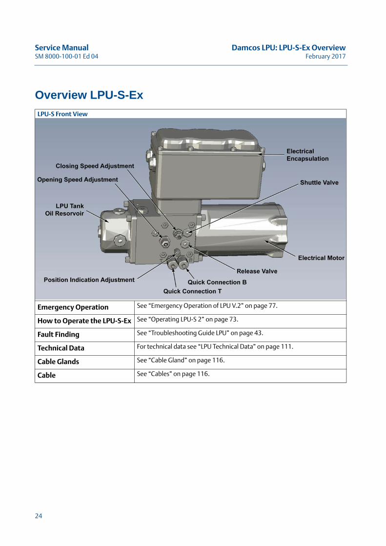
Overview LPU-S-Ex
LPU-S Front View
Emergency Operation See “Emergency Operation of LPU V.2” on page 77.
How to Operate the LPU-S-Ex See “Operating LPU-S 2” on page 73.
Fault Finding See “Troubleshooting Guide LPU” on page 43.
Technical Data For technical data see “LPU Technical Data” on page 111.
Cable Glands See “Cable Gland” on page 116.
Cable See “Cables” on page 116.
24
Damcos LPU: LPU-S-Ex Overview Service ManualFebruary 2017 SM 8000-100-01 Ed 04
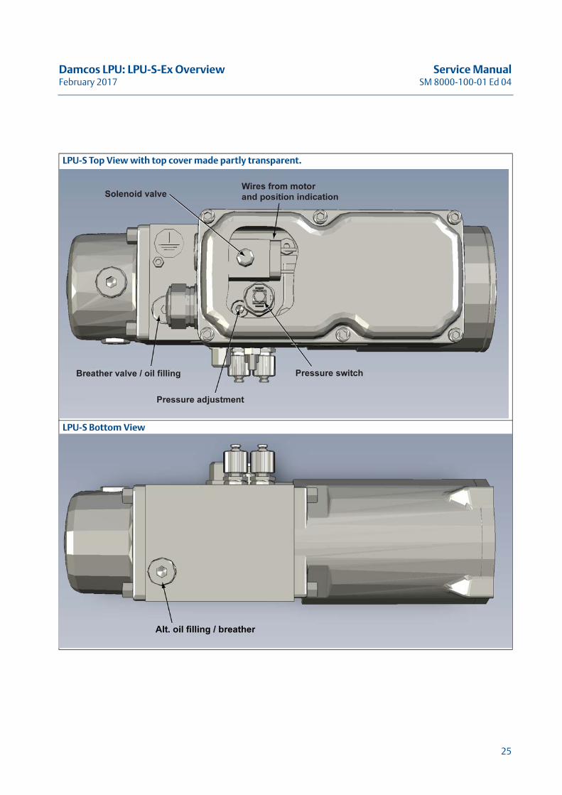
LPU-S Top View with top cover made partly transparent.
LPU-S Bottom View
25

Service Manual Damcos LPU: LPU-S-Ex OverviewSM 8000-100-01 Ed 04 February 2017
26
Damcos LPU: LPU-S-Ex-ia Overview Service ManualFebruary 2017 SM 8000-100-01 Ed 04
LPU-S-Ex-ia OverviewThis Chapter Describes the LPU-S-Ex-ia with
Overview and Handling Instructions
27
Service Manual Damcos LPU: LPU-S-Ex-ia OverviewSM 8000-100-01 Ed 04 February 2017
Overview LPU-S-Ex-ia
LPU-S Front View
Emergency Operation See “Emergency Operation of LPU V.2” on page 77.
How to Operate the LPU-S See “Operating LPU-S 2” on page 73.
Fault Finding See “Troubleshooting Guide LPU” on page 43.
Technical Data For technical data see “LPU Technical Data” on page 111.
Cable Glands See “Cable gland LPU-Ex and LPU-Ex-ia” on page 116.
Zener barrier See “Zener barrier LPU-Ex-ia” on page 117.
28
Damcos LPU: LPU-S-Ex-ia Overview Service ManualFebruary 2017 SM 8000-100-01 Ed 04
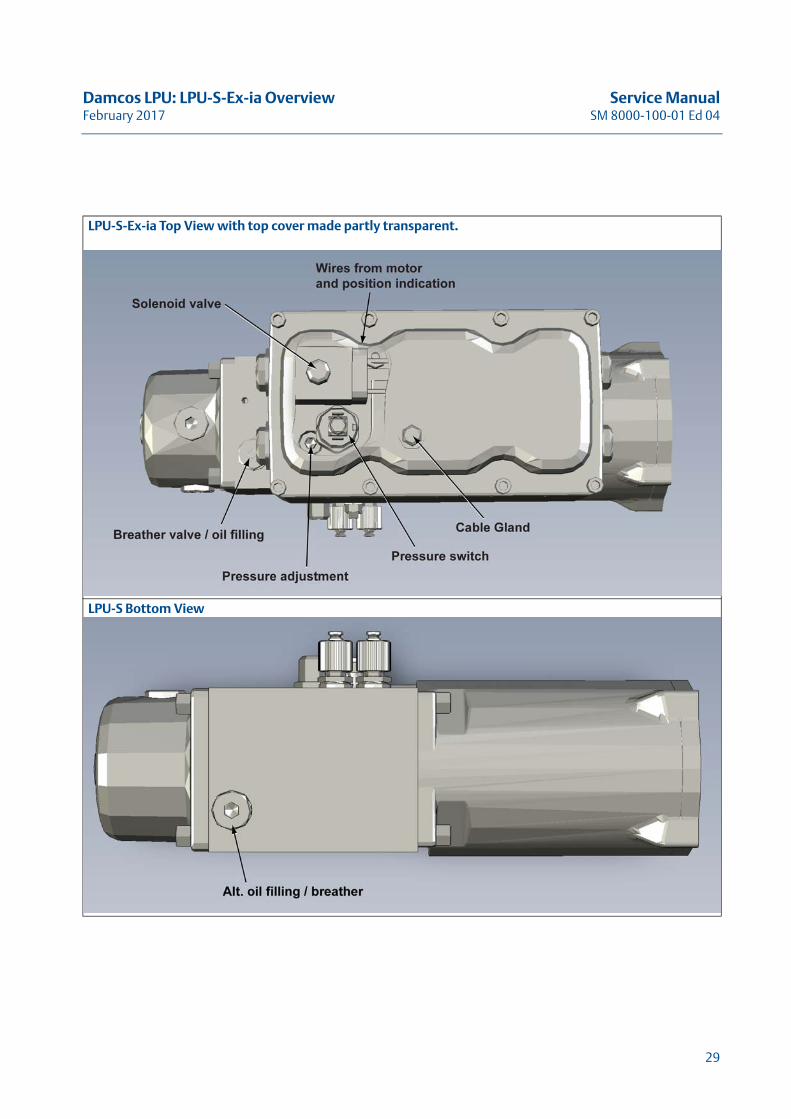
LPU-S-Ex-ia Top View with top cover made partly transparent.
LPU-S Bottom View
29

Service Manual Damcos LPU: LPU-S-Ex-ia OverviewSM 8000-100-01 Ed 04 February 2017
30
Damcos LPU: LPU-D Overview Service ManualFebruary 2017 SM 8000-100-01 Ed 04
LPU-D OverviewThis Chapter Describes the LPU-D with
Overview and Handling Instructions
31
Service Manual Damcos LPU: LPU-D OverviewSM 8000-100-01 Ed 04 February 2017
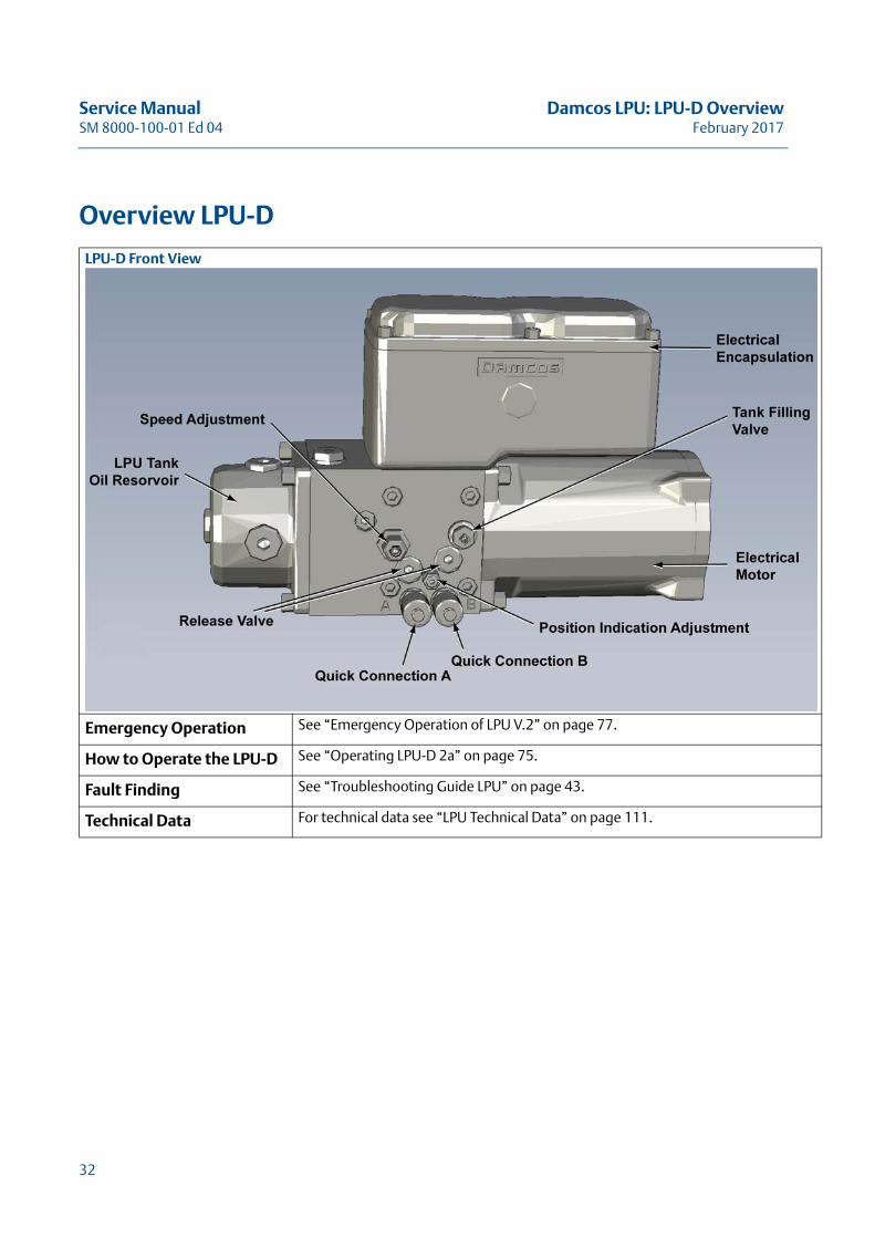
Overview LPU-D
LPU-D Front View
Emergency Operation See “Emergency Operation of LPU V.2” on page 77.
How to Operate the LPU-D See “Operating LPU-D 2a” on page 75.
Fault Finding See “Troubleshooting Guide LPU” on page 43.
Technical Data For technical data see “LPU Technical Data” on page 111.
32
Damcos LPU: LPU-D Overview Service ManualFebruary 2017 SM 8000-100-01 Ed 04
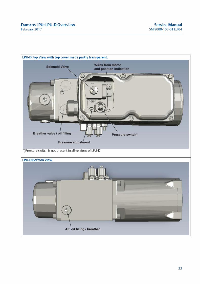
LPU-D Top View with top cover made partly transparent.
*)Pressure switch is not present in all versions of LPU-D!
LPU-D Bottom View
33

Service Manual Damcos LPU: LPU-D OverviewSM 8000-100-01 Ed 04 February 2017
34
Damcos LPU: LPU-D-Ex Overview Service ManualFebruary 2017 SM 8000-100-01 Ed 04
LPU-D-Ex OverviewThis Chapter Describes the LPU-D-EX with
Overview and Handling Instructions
35
Service Manual Damcos LPU: LPU-D-Ex OverviewSM 8000-100-01 Ed 04 February 2017
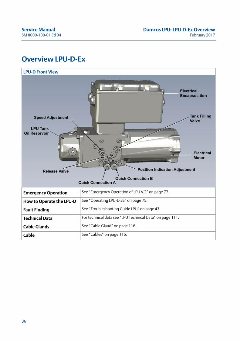
Overview LPU-D-Ex
LPU-D Front View
Emergency Operation See “Emergency Operation of LPU V.2” on page 77.
How to Operate the LPU-D See “Operating LPU-D 2a” on page 75.
Fault Finding See “Troubleshooting Guide LPU” on page 43.
Technical Data For technical data see “LPU Technical Data” on page 111.
Cable Glands See “Cable Gland” on page 116.
Cable See “Cables” on page 116.
36
Damcos LPU: LPU-D-Ex Overview Service ManualFebruary 2017 SM 8000-100-01 Ed 04
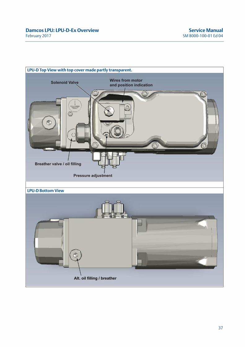
LPU-D Top View with top cover made partly transparent.
LPU-D Bottom View
37

Service Manual Damcos LPU: LPU-D-Ex OverviewSM 8000-100-01 Ed 04 February 2017
38
Damcos LPU: LPU-D-Ex-ia Overview Service ManualFebruary 2017 SM 8000-100-01 Ed 04
LPU-D-Ex-ia OverviewThis Chapter Describes the LPU-D-Ex-ia with
Overview and Handling Instructions
39
Service Manual Damcos LPU: LPU-D-Ex-ia OverviewSM 8000-100-01 Ed 04 February 2017
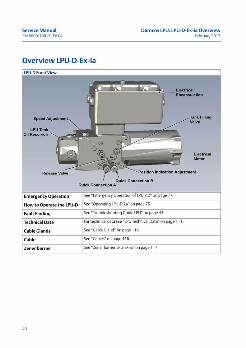
Overview LPU-D-Ex-ia
LPU-D Front View
Emergency Operation See “Emergency Operation of LPU V.2” on page 77.
How to Operate the LPU-D See “Operating LPU-D 2a” on page 75.
Fault Finding See “Troubleshooting Guide LPU” on page 43.
Technical Data For technical data see “LPU Technical Data” on page 111.
Cable Glands See “Cable Gland” on page 116.
Cable See “Cables” on page 116.
Zener barrier See “Zener barrier LPU-Ex-ia” on page 117.
40
Damcos LPU: LPU-D-Ex-ia Overview Service ManualFebruary 2017 SM 8000-100-01 Ed 04
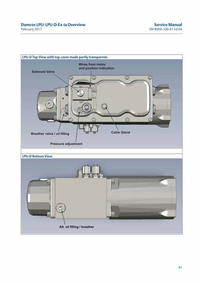
LPU-D Top View with top cover made partly transparent.
LPU-D Bottom View
41

Service Manual Damcos LPU: LPU-D-Ex-ia OverviewSM 8000-100-01 Ed 04 February 2017
42
Damcos LPU: Troubleshooting Guide LPU Service ManualFebruary 2017 SM 8000-100-01 Ed 04
Troubleshooting Guide LPUThis Chapter Describes how to Identify
and Correct minor Problems for LPU
43

Service Manual Damcos LPU: Troubleshooting Guide LPUSM 8000-100-01 Ed 04 February 2017
44
Damcos LPU: Troubleshooting Guide LPU Service ManualFebruary 2017 SM 8000-100-01 Ed 04
Fault Finding List LPU
ACTUATOR CONNECTED PROBLEM“Actuator only running in one direction (the unit can either only open or only close)” on page 53“LPU-D not maintaining pressure on actuator” on page 57“Spring actuator only partly closing or not starting to close” on page 58“Too little tank volume for operating actuator” on page 66“Spring actuator do not close by emergency hand pump operation” on page 69
ELECTRICAL PROBLEM“Unit drawing too much current” on page 65
EMERGENCY OPERATION“Emergency operation by key giving oil spillage through breather valve” on page 59“Emergency operation by key not possible, hydraulically locked” on page 59“Emergency operation by hand pump giving oil spillage through breather valve” on page 59“Emergency operation by hand pump not possible” on page 60“Spring actuator do not close by emergency hand pump operation” on page 69
LPU-D“LPU-D not maintaining pressure on actuator” on page 57
LPU-Ex“LPU-Ex motor do not run” on page 70“LPU-Ex has to be bulkhead mounted because of too little space or zone 0 at actuator” on page 71
LPU-S“LPU-S frequently restarting in open position” on page 47
MOTOR“LPU-Ex motor do not run” on page 70“Motor not running and is hot” on page 49“Motor not running and is Cold” on page 49“Motor not stopping” on page 50“Motor running hot, LPU is operating normally” on page 56“Motor running for a short time and stops High pressure on the port to which oil is led” on page 62“Motor running for a short time and stops” on page 62“Motor ”diving” in RPM in end position ” on page 63“Motor ”diving” in RPM as spring actuator opens” on page 63
OIL LEAKAGE“LPU leaking from bleeder valve when hand pump is mounted” on page 68“Oil spillage, generally” on page 64“Oil in electronic connection box” on page 64“Oil spillage from breather valve” on page 64
45
Service Manual Damcos LPU: Troubleshooting Guide LPUSM 8000-100-01 Ed 04 February 2017
POSITION INDICATOR“Position indicator errors” on page 72
PUMP“Pump rendering too low (or no) pressure in one or both directions” on page 51“Noise from pump, but only at low pressure” on page 54“Noise from pump, but only at high pressure” on page 55“Noise from pump at both high and low pressure” on page 55“Pump not rendering sufficient oil at high pressure (“valve running too slowly”)” on page 61“Pump not rendering sufficient oil at low pressure (“valve running too slowly”)” on page 61
PRESSURE“Pump rendering too low (or no) pressure in one or both directions” on page 51“LPU-D not maintaining pressure on actuator” on page 57“LPU cannot raise pressure after hand pump operation (but no problems after remote operation)” on page 67
SOLENOID VALVE“Solenoid valve not working” on page 52
46
Damcos LPU: Troubleshooting Guide LPU Service ManualFebruary 2017 SM 8000-100-01 Ed 04
LPU-S frequently restarting in open positionAction: Place pressure gauge on quick connection B.
Read maximum pressure and observe if pressure drops when motor stops.
Then if: 1. Pressure is raised to approx. 150 bar, but drops to 95 - 105 bar before motor is restarted.Goto “Leakage in the hydraulic system between check valve and actuator or in actuator” on page 47.
2. Pressure is raised to approx. 150 bar and motor stops, but is restarted before pressure drops below 115 bar. Goto “Fault on pressure switch or wires, possibly on printed circuit board” on page 47.
3. Pressure is raised to below 120 bar and drops to 90 - 110 bar before motor is restarted. Goto “Large leakage in the hydraulic system, or misadjusted safety valve” on page 48.
1. Leakage in the hydraulic system between check valve and actuator or in actuator
Action: Mount hand pump, pressure gauge is already mounted (see above), and open actuator fully by hand pump.
Then if: • Pressure remains constantLeakage in solenoid valve or leakage at check valve in valve block:
– Check for leakage in solenoid valve.– Check valve in valve block for external leakage, e.g. at pressure switch or closing speed adjust-
ment. Check for external leakage and if no leakage is found replace solenoid valve or check valve.
• Pressure dropsLeakage in bypass valve at actuator, release valve, shuttle valve, emergency valve or actuator.
– Check o-rings on emergency slide and shuttle valve, possibly replace release valve or shuttle valve if shuttle valve is version with internal slide.
– Check that bypass valve in actuator is closed.– Possibly dismount LPU from actuator and check if actuator has leakage, internal or external.
2. Fault on pressure switch or wires, possibly on printed circuit board
Action: Wires to pressure switch are dismounted from pressure switch and connected to each others, simu-lating high pressure.
Caution! For LPU power these wires are supplied by 230 V. When the LPU is energized, the motor must run for 7 - 12 seconds, then stop, and not start until the wires are disconnected from each other.
Pressure Switch is electrically measured fully pressurized for short breaks (loose connections). Pres-sure gauge is mounted on quick connection for B and pressure is read when pressure switch breaks.
Then if: • Pressure switch breaks above 105 bar
47
Service Manual Damcos LPU: Troubleshooting Guide LPUSM 8000-100-01 Ed 04 February 2017
– Pressure switch is adjusted, so that pressure switch breaks by falling pressure at 100 ±5 bar. Pressure switch must close below 125 bar by rising pressure.
• Short breaks of pressure switch
– Replace pressure switch! See “Replace pressure switch” on page 109.• Pressure switch breaks below 105 bar, no short breaks
– Check electrical connections from pressure switch. If no other faults are detected, replace printed circuit board. See “Replace Printed Circuit Board” on page 105.
3. Large leakage in the hydraulic system, or misadjusted safety valve
Action: Mount hand pump, actuator is fully opened by hand pump, pressure gauge is mounted.
Then if: • Pressure remains constantLeakage in solenoid valve, quick connection B or external leakage, e.g. at pressure switch. Possi-bly too low adjusted pressure at pump relief valve (pump safety valve).
– Check for external leakage, if no leakage, adjust pump pressure (see “Pump pressure adjust-ment for LPU” on page 85). If this cannot be adjusted any higher, check internal sealings and flow reducing valve (opening speed adjustment).
– Replace solenoid valve (see “Replace Solenoid Valve in LPU-D” on page 107), flow reducing valve or sealings. Then safety valve is readjusted to 150 bar (see “Pump pressure adjustment for LPU” on page 85).
Note! If oil has too low viscosity or is very hot this might be the reason for a too low pressure.
• Pressure dropsLeakage in actuator, or possibly bypass valve, release valve, emergency valve or shuttle valve.
– Check o-rings on shuttle valve and emergency valve, possibly replace release valve, see “Replace release valve in LPU” on page 99.
– Check for external leakage.
48
Damcos LPU: Troubleshooting Guide LPU Service ManualFebruary 2017 SM 8000-100-01 Ed 04
Motor not running and is hotAction: Check that electrical connections to motor and capacitor are OK! Open bypass to release possible
pressure on pump and try to run the motor with opened bypass.
Then if: • Motor is running, but stops when bypass is closed.Incorrectly connected motor or fault on motor or wires.
– Low supply voltage.– Defective flow reducing valve, see “Motor ”diving” in RPM in end position ” on page 63.
• Motor is not running at all, even though bypass is opened.
– Disconnect current to LPU for measurement of resistance from N to CL and from N to OP on printed circuit board (the easiest way is to disconnect the capacitor). Resistance must be 15 . The capacitor can on rare occasions be defective.If connections and resistance are OK, the pump has stuck. New pump set is then mounted, see “Replace Pump in LPU” on page 93. Reason for defective pump should be found, e.g. insufficient quantity of oil, no stop of motor, impurities in oil etc.
Note! For LPU-Ex the temperature cut-off box might have interrupted power to motor due to too high motor temperature. If this is the case the motor needs time to cool down, then 24 V to LPU-Ex is interrupted for 10 seconds and LPU-Ex should be ready to run again.
Motor not running and is ColdAction: • Check that there is 220 - 230 V AC over “N” and “open” or “close”, respectively when trying to
operate.
• Check that electrical connections to motor are OK. If the black wire is not connected, motor can-not run.
• Dismount the motor wires. Check the resistance on the printed circuit board from “N” to the centre motor wire, and from “open” and “close”, respectively to the two other motor connec-tions. There must not be a measurable resistance.
• Check the resistance in the motor itself, there must be approximately 15 . between the black wire and each of the others. If the resistance differs widely, the motor is to be replaced.
Note! For LPU-Ex the temperature cut-off box will interrupt power to motor if 24 V is not present or bounces when it is connected.
49
Service Manual Damcos LPU: Troubleshooting Guide LPUSM 8000-100-01 Ed 04 February 2017
Motor not stoppingAction: • The pressure on B-port is measured.
If the pressure is below 120 bar, while motor is running, see “Pump rendering too low (or no) pressure in one or both directions” on page 51.
• Wires to the pressure switch are dismounted and connected to each others, simulating high pressure.
Caution! LPU-Power wires are supplied by 230 V. When LPU terminal (“open”) is energized in the relevant direction, motor must stop after 7 - 12 seconds.LPU-S-power must not be restarted before wires are disconnected.LPU-D-power must not be restarted before power is disconnected and reconnected again.
• If pressure switch is correctly connected, and the pressure is correct, check that pressure switch is closing as required. Pressure switches must close at maximum 125 bar and break between 95 to 105 bar.Adjust and if necessary replace pressure switches, see “Replace pressure switch” on page 109.
LPU-D-P-NetIf motor does not stop at all, the printed circuit board must be replaced, see “Replace Printed Circuit Board” on page 105.If the motor runs longer than normal, but then stops, the fault should be found in the position indica-tor, the calibration of the analogue indicator or setup of extra time in circuit board. Check, that the position signal is really “0” or “100”.
LPU-S-P-NetIf motor does not stop at all and pressure on B-port is above 125 bar, the printed circuit board must be replaced, see “Replace Printed Circuit Board” on page 105. If the motor runs longer than normal, but then stops, the fault should be found in the position indica-tor, the pressure switch, the calibration of the analogue indicator or setup of extra time in circuit board. Check that the position signal really is “100”.
LPU Power ControlCheck that the pressure switch is correctly connected. See “Pump rendering too low (or no) pressure in one or both directions” on page 51.
50
Damcos LPU: Troubleshooting Guide LPU Service ManualFebruary 2017 SM 8000-100-01 Ed 04
Pump rendering too low (or no) pressure in one or both directions
Action: • Check that solenoid valve is clicking at connection. If not see “Solenoid valve not working” on page 52.
• If pump does not render any pressure at all check oil level. Mount a plug giving a possibility of connecting compressed air instead of breather valve and pressurize tank with maximum 2.5 bar, while the pump is running. If air pressure in tank does not solve the problem, or if the pump renders pressure (but too low), hand pump with pressure gauge is mounted and actuator is fully opened by hand pump.
LPU-DIf no opening pressure check that by-pass for tank filling (in front of LPU) is closed.
LPU-PowerCheck that power supply is connected to terminal “open” and that terminal “close” is not connected.
If pressure remains constantly lowAt too low pressure in one direction (LPU-S) or both directions (LPU-D) the safety valve is adjusted according to instruction (see “Pump pressure adjustment for LPU” on page 85). If higher pressure cannot be obtained, there is a possible leakage in the solenoid valve, or at DPCV-slide (LPU-D), or at clearance between pump stator and rotor.De-airing the flow reducing valve may be necessary, see “Pump not rendering sufficient oil at low pressure (“valve running too slowly”)” on page 61.
If pressure drops quicklyLeakage in bypass valve (actuator), shuttle or emergency valve (LPU-S) or release valve. Check o-rings on valves and if necessary replace release valve (see “Replace release valve in LPU” on page 99) or shuttle valve.
51
Service Manual Damcos LPU: Troubleshooting Guide LPUSM 8000-100-01 Ed 04 February 2017
Solenoid valve not workingAction: • Check that solenoid valve is energized (230 V on terminals “N” and “SV”).
• If coil is energized, but solenoid valve does not work, the resistance of the coil is measured (LPU-D). The coil must have a resistance of approximate 520 for LPU-D. Due to a diode bridge resis-tance cannot be measured for LPU-S coil. Another way to check the coil is to loosen it and try to lift the coil when energized. If coil does not work, it is replaced.
• If coil works, the valve is to be replaced. See “Replace Solenoid Valve in LPU-D” on page 107.
52
Damcos LPU: Troubleshooting Guide LPU Service ManualFebruary 2017 SM 8000-100-01 Ed 04
Actuator only running in one direction (the unit can either only open or only close)
LPU-DIf LPU-D can close, but not open check by-pass valve for oil filling. Check that solenoid valve is pow-ered and working and that free travel of solenoid valve slide is OK.
LPU-SIf actuator can close, but not open see “Pump rendering too low (or no) pressure in one or both direc-tions” on page 51. If actuator can open, but not close, see “Spring actuator only partly closing or not starting to close” on page 58.
Note! BRCF and KF can always be closed by opening bypass valve at actuator. KFR can be closed opening bypass valve and lifting valve for emergency operation by hand pump.
53
Service Manual Damcos LPU: Troubleshooting Guide LPUSM 8000-100-01 Ed 04 February 2017
Noise from pump, but only at low pressureAction: Adjust speed from maximum to minimum (see “Speed adjustment for Actuator on LPU (v.2)” on
page 83). If possible, place key on emergency operation shaft of the actuator and hold against rotat-ing direction (i.e. operating pressure must be approximate 30 bar) (only possible for BRC 125, 250, 500).
Warning! Beware of huge force, actuator cannot be stopped by hand!
Then if: • Sound disappearsToo low compression of O-ring on motor shaft, so that rotor is vibrating on coupling. Replace O-ring.
• Sound is unchangedA pump piston is operating too tightly and does not follow the ball bearing curve during move-ment. At relatively high pressure it is pressed out hydraulically. The sound can disappear at start-ing-up. Otherwise pump is dismounted and pistons and rotor are checked for coverings or burrs.
Note! If pump rotor has to be replaced the stator version has to be checked (check placement and number of expanding plugs). If stator versions are different both rotor and stator must be exchanged (complete pump set, see “Replace Pump in LPU” on page 93).
54
Damcos LPU: Troubleshooting Guide LPU Service ManualFebruary 2017 SM 8000-100-01 Ed 04
Noise from pump, but only at high pressureReason: • Air in the pump if actuator has not been properly de-aired. Check oil level in tank.
• Too small tank volume for large actuators or long pipes in system.
• Piston in pump is sticking. A pump piston is operating too tightly and does not follow the ball bearing curve during move-ment. At relatively high pressure it is pressed out hydraulically. The sound can disappear at start-ing-up. Otherwise pump is dismounted and pistons and rotor are checked for coverings or burrs.
Note! If pump rotor has to be replaced the stator version has to be checked (check placement and number of expanding plugs). If stator versions are different both rotor and stator must be exchanged (complete pump set, see “Replace Pump in LPU” on page 93).
Noise from pump at both high and low pressureReason: Motor and pump are not co-axial, pump stator is not mounted firmly in the block.
Action: • Check steering pins between blocks.
• Dismount pump and check that remounted stator is perpendicular to valve block. See “Replace Pump in LPU” on page 93 for more information.
55
Service Manual Damcos LPU: Troubleshooting Guide LPUSM 8000-100-01 Ed 04 February 2017
Motor running hot, LPU is operating normally
Caution! Motor is designed for 25% duty cycle only.
Action: • LPU-S Observe that LPU does not restart. If it is restarting frequently, the motor is running hot. See“LPU-S frequently restarting in open position” on page 47.
• Measure the supply voltage (220 - 230 V AC) to LPU.If it differs widely from the required voltage, the voltage must be modified.
• Measure the resistance over the motor windings, on the terminal (easiest with disconnected capacitor). There must be approximately 15 between “N” and “OPEN” and “CLOSE” respec-tively.If this resistance is not observed, the motor is to be replaced.
• The mechanical resistance of the motor can be too high.If it cannot be turned easily with the fingers, it is to be replaced.
• The mechanical resistance of the pump can be too high, if ball bearing is blocked.Dismount valve block and pump rotor as to change pump (see “Replace Pump in LPU” on page 93) and check if ball bearing can rotate freely.
56
Damcos LPU: Troubleshooting Guide LPU Service ManualFebruary 2017 SM 8000-100-01 Ed 04
LPU-D not maintaining pressure on actuator
Pressure drops only on 1 port• Leakage in check valves for DPCV or release valve.
Change check valves for DPCV.
• A leakage in actuator might give pressure drop on only one port. Replace the seal set in actuator with a new one.
Pressure drops on both portsLeakage in bypass valve (actuator) or actuator.
• Check bypass valve, possibly replace release valve (see “Replace release valve in LPU” on page 99).
• Check actuator.
57
Service Manual Damcos LPU: Troubleshooting Guide LPUSM 8000-100-01 Ed 04 February 2017
Spring actuator only partly closing or not starting to closeAction: Check that throttle valve for adjustment of closing speed is not blocked.
Open bypass while motor is not operated.
Then if: • Spring actuator closesSolenoid valve coil is still energized while valve is required to be closed! This might be due to that valve has been opened by hand pump or filter below pressure switch is blocked or too fast closing speed so that emergency valve has no pressure and is closing before actuator is closed. If this is the case then:
– repeat opening and closing command (by remote operation) for LPU. If closing does not function check that the power for the solenoid valve is turned off. If not check relay in control cabinet (power controlled with separately connected solenoid valve), or on printed circuit board (P-Net). Else remove coil from solenoid valve. Check filter below pressure switch (valve must be closed). Adjust closing speed valve to fully closed, open it 1 revolution and check again. If the actuator now closes closing speed can be increased step by step. If closing speed cannot be sufficient then B-line between LPU and actuator is checked for blocks that can throttle oil flow.
• Spring actuator remains openThe fault is to be found outside the LPU.For KFR push button for emergency operation might be blocked. Valve is sticking, or fault on spring actuator.
58
Damcos LPU: Troubleshooting Guide LPU Service ManualFebruary 2017 SM 8000-100-01 Ed 04
Emergency operation by key giving oil spillage through breather valve
Reason: When valve is emergency operated by key, oil is pumped from actuator to LPU tank and further on to the actuator. If the oil flow from LPU tank to actuator gives more than 3 bar pressure drop, the oil can be pressed through the breather valve instead of back to actuator.
Action: Carrying out emergency operation at the same opening and closing speed to which the valve is set at remote operation can solve the problem.
Caution! Avoid replacement of breather valve with plug, as this might result in too high pressure at motor shaft sealing.
Emergency operation by key not possible, hydraulically locked
Reason: Bypass not active or bypass valve is blocked.
Action: Open bypass valve and keep it opened during emergency operation. If emergency operation is still locked - bypass valve is to be dismounted and checked. If bore contains dirt, it has to be removed.
Emergency operation by hand pump giving oil spillage through breather valve
Reason: Tank pressure in LPU is too high. The pressure drop over quick connections due to very fast operation or defective or not properly connected quick connections. If LPU is bulkhead mounted the pressure drop might be in piping as well if they are long or if the inside diameter is narrow. If oil cannot return to the hand pump tank, an LPU-S may be opened without problems. When valve closes again, the LPU tank overflows.When LPU’s closed system is filled with oil, the exceeding oil is let out through the breather valve to prevent overpressure in the LPU.
59
Service Manual Damcos LPU: Troubleshooting Guide LPUSM 8000-100-01 Ed 04 February 2017
Emergency operation by hand pump not possibleReason: • Hand pump is building up pressure, but actuator is not moving
– Slide for shuttle valve is sticking, so that change over to emergency operation cannot take place (LPU-S).
– Outlet from actuator blocked so that return oil cannot pass.– Fault on quick connections, so that check valve in hand pump quick connection is not open-
ing.• Hand pump is pumping oil, but cannot build up pressure
– Leakage in DPCV (LPU-D), bypass valve, release valve, emergency valve (LPU-S) or actuator• After a few strokes, hand pump is not pumping oil
– Insufficient oil in hand pump tank
60
Damcos LPU: Troubleshooting Guide LPU Service ManualFebruary 2017 SM 8000-100-01 Ed 04
Pump not rendering sufficient oil at high pressure (“valve running too slowly”)
Reason: LPU is built up, so that oil quantity from pump, independent of adjusted speed, is reduced to approx-
imate 240 cm3/min from pressure exceeding 75 bar. If flow is considerably below this quantity, see “Pump rendering too low (or no) pressure in one or both directions” on page 51.The pressure should only exceed 65 bar for a few seconds, when breaking valve away or closing valve.
Pump not rendering sufficient oil at low pressure (“valve running too slowly”)
Action: • Check adjustment of opening and closing speed (see “Speed adjustment for Actuator on LPU (v.2)” on page 83).
• While pump is running at high pressure in end position, valve housing for speed adjustment is loosened by a 19 mm wrench (must be turned maximum 3 turns, as there is full pump pressure below housing), until airless oil is running from it. Then valve housing is tightened, and pump flow is checked again. If pump flow is still not OK, dismount adjusting screw for speed control, check with a screw driver that the ball bearing behind this can be moved back and forth by press-ing it. Check mobility of the piston in valve housing for speed adjustment.
• Dismount tank and check if filter in suction pipe is blocked.
• Dismount tank and valve block, check the mobility of the bearing, and observe if any pistons in rotor are sticking. Stator is dismounted (pressed out from the tan side), and blown through, to remove plugging, if any, in the longitudinal holes.
• Remounting of stator: stator must be pressed in until direction pin is below surface of block. When seated correctly, the free stator length is approximate 19 mm. Do not use metal hammer directly on the stator. (See “Replace Pump in LPU” on page 93).
61
Service Manual Damcos LPU: Troubleshooting Guide LPUSM 8000-100-01 Ed 04 February 2017
Motor running for a short time and stopsHigh pressure on the port to which oil is led
Action: Mount pressure gauge on quick connection on return oil from actuator (LPU-D). At the same time check that actuator is moving.
Then if: • High pressure on return oil. Actuator is not moving, or is hardly movingDPCV does not open check valve for return oil. Check slide, sealings and check-valves for DPCV.
• Low pressure on return oil. Actuator is running, but not to end positionOperating pressure for actuator too high due to blocking in return, could be dirt in holes near the port surface or in actuator.
• Low pressure on return oil. Actuator is not moving, or is hardly movingOperating pressure for actuator too high due to blocking in return, could be dirt in holes near the port surface or in actuator.Fault in actuator, valve (requires a too high torque or more than 7 seconds before breaking away from the seat), or choice of actuator for the valve in question.
Motor running for a short time and stopsReason: Pressure switch does not break, or fault on control print.
Action: • Try dismounting a wire for the pressure switch in question. LPU shall then operate as long as ter-minal is energized. If not so, there is a fault on the printed circuit board which is then replaced (see “Replace Printed Circuit Board” on page 105).
• Control card receives a signal for stop of motor from pressure switch. For LPU-S and LPU-D-Power, pressure switch connections and adjustment are to be checked. Pressure switch is possi-bly replaced (see “Replace pressure switch” on page 109).
62
Damcos LPU: Troubleshooting Guide LPU Service ManualFebruary 2017 SM 8000-100-01 Ed 04
Motor ”diving” in RPM in end position Reason: Voltage too low, pump relief valve misadjusted, defective flow reducing valve (the displacement of
the pump is not reduced at high pressure), fault in motor, or faulty connection of motor. Possibly fault in capacitor/connection.
Action: • Check voltage over the terminals during operation. If it is considerably below 220 V AC, the fault is to be found here. Take corrective measures. (LPU can operate down to 185V at 60 Hz, but such a low voltage is an indication of something being wrong).
• Check connection of motor.
• Check connection of capacitor.
• Check the maximum pressure (connect a pressure gauge to the quick connection pressurised). Possibly adjust relief valve to 150 bar.
• Dismount adjusting screw for speed control, check with a screwdriver that the ball bearing behind this can be moved back and forth by pressing it.
Motor ”diving” in RPM as spring actuator opensReason: Voltage too low, mechanical resistance in ball bearing around pump, faulty connected motor or fault
in capacitor.
63
Service Manual Damcos LPU: Troubleshooting Guide LPUSM 8000-100-01 Ed 04 February 2017
Oil spillage, generallyAvoid starting motor until the correct level in tank has been ensured. After elimination of faults, replenish tank with the correct oil for the specific system.
Oil in electronic connection boxAction: • At a large oil volume in electric connection box: Avoid starting the motor until having ensured
that the oil level in tank is OK.
• Check pressure switch and solenoid valve for visible leakage, possibly by starting pump.
• For LPU-S, leakage at pressure switch or solenoid valve will result in a pressure drop, so that the LPU motor / pump restarts if this function is engaged.
• Possible leakage from safety valve cannot be positively identified, until electronic connection box has been dismounted.
• Leakage from actuator, led through the position indicator can occur at leakage from actuator to indicator. In special cases, oil may even be led through the power/bus cables from one LPU to the next.
• At leaking shaft seal on the electrical motor, the oil can run through motor and up in electronic connection box.
• After repair of defects, the tank is replenished with the correct oil for the specific system.
Oil spillage from breather valve• Oil spillage at emergency operation: see “Emergency operation by key giving oil spillage through
breather valve” on page 59 or “Emergency operation by hand pump giving oil spillage through breather valve” on page 59.
• Oil spillage during operation when motor is changing direction: Compressed air in actuator. Actuator is to be de-aired.Especially linear actuators (KC, KF and KFR) may have to be loosened from valve to be able to close completely before de-airing of actuator.
• Oil spillage when BRCF closes: Possibly air in actuator, actuator is to be de-aired. Breather valve shall only be placed in BRCF or in LPU, not in both. Breather valve to be placed at highest possible tank level. Too fast closing of actuator giving a high return pressure at closing letting oil out of breather valve. Adjust closing speed to slower closing.
• Oil spillage when KF or KFR closes: Possibly air in actuator, actuator is to be de-aired. Breather valve must always be placed on top of KFR, and in LPU, where breather valve has to be placed at highest possible tank level. Too fast closing of actuator giving a high return pressure at closing letting oil out of breather valve. Adjust closing speed to slower closing.
• Oil spillage at temperature rise in LPU-system: Oil tank overfilled or too great expansion at heat-ing up, dependent on oil volume. At a large oil spillage due to heating up, an extended tank should be used.
64
Damcos LPU: Troubleshooting Guide LPU Service ManualFebruary 2017 SM 8000-100-01 Ed 04
Unit drawing too much currentReason: • Mechanical resistance in motor
• Mechanical resistance in pump
• Too small winding resistance in motor meaning a 110 V motor has been used instead of 230 V motor
• Too high or too low supply voltage
• Too low frequency
• Faulty electrical connection of motor
• Defective capacitor
65
Service Manual Damcos LPU: Troubleshooting Guide LPUSM 8000-100-01 Ed 04 February 2017
Too little tank volume for operating actuator
LPU• Incorrect oil filling and de-airing of actuator. Check oil filling.
• Too high compressibility of oil in pipes between hand pump and LPU or between LPU and actua-tor. Try more carefully de-airing of piping. It might be necessary to use an expansion tank at LPU. Expansion tank at hand pump is not allowed as it gives risk of oil spillage at breather valve.
LPU-SNo connection from LPU-tank and hand pump tank to actuator tank/spring chamber. Hand pump tank and LPU tank need tank connection to actuator to maintain constant oil volume in system for mix of emergency and remote operation.
For large actuators Oil compression by pressurizing actuator needs more oil than a standard tank can give. Use pressure tank for LPU. This is the case for e.g. BRC/BRCF 16000, BRC 32000, BRCF 4000 HT, BRCF 8000 HT, KC 325 and KC 400.
66
Damcos LPU: Troubleshooting Guide LPU Service ManualFebruary 2017 SM 8000-100-01 Ed 04
LPU cannot raise pressure after hand pump operation (but no problems after remote operation)
Reason: • Leakage from LPU to hand pump.
– Portable hand pump must be disconnected. – Make sure that by-pass at possible bulkhead hand pump is closed. – Try to operate valve in the selected direction by hand pump first, then by LPU. If LPU can raise
pressure now, the DPCV valve slide has too high friction. If problem is not solved DPCV is leak-ing due to defect non return valve or slide is sticking.
67
Service Manual Damcos LPU: Troubleshooting Guide LPUSM 8000-100-01 Ed 04 February 2017
LPU leaking from bleeder valve when hand pump is mounted
Reason: For LPU-S• Bad T-connection from LPU to hand pump:
– Check piping and connections. – Check that no by-pass valve is placed in T-side of hand pump, as free T-flow is essential for
function of hand pump.
For LPU-D• At remote operating LPU is compressing oil in piping for hand pump or, when bulkhead mounted
LPU, for actuator. The oil volume needed for compressing this oil is depending on oil volume in pipes and proper de-airing. This oil volume will be taken from hand pump tank and cannot be returned because of DPCV in hand pump.
– If de-airing of piping is OK a pressure tank at LPU has to be mounted.
Caution! Pressure tank at hand pump is not allowed.
68
Damcos LPU: Troubleshooting Guide LPU Service ManualFebruary 2017 SM 8000-100-01 Ed 04
Spring actuator do not close by emergency hand pump operation
Reason: • Spring actuators will not close by changing bulkhead hand pump to close, as there will be no pressure rise to open the DPCV.
– Close actuator through by-pass valve at hand pump or actuator instead. Close by-pass valve when the actuator is fully closed.
For KFR
If KFR is emergency opened at the actuator, an opening operation followed by closing the actuator is necessary. Opening operation can be made by hand pump or remote control.
69
Service Manual Damcos LPU: Troubleshooting Guide LPUSM 8000-100-01 Ed 04 February 2017
LPU-Ex motor do not runReason: LPU-Ex-motors contain temperature sensors that have to be reset manually. After motor cut-off by
temperature sensors they have to be reset by turning off 24 V power for at least 10 sec.If this don’t solve the problem, see “Motor not running and is hot” on page 49 and “Motor not run-ning and is Cold” on page 49.
70
Damcos LPU: Troubleshooting Guide LPU Service ManualFebruary 2017 SM 8000-100-01 Ed 04
LPU-Ex has to be bulkhead mounted because of too little space or zone 0 at actuator
Like other LPU’s LPU-Ex can be bulkhead mounted by means of BB-block or BB-VPI, but then needs an intrinsically safe position indicator. All LPU-Ex can be delivered with integrated intrinsically safe outlet for position indicator (ia) to solve the problem.
Note! For LPU-Ex with ia-outlet the hole for DPI in LPU must contain a special plug to ensure that flameproof enclosure of LPU-Ex is maintained. This plug is delivered with ia-parts and must always be used for ia-versions.
71
Service Manual Damcos LPU: Troubleshooting Guide LPUSM 8000-100-01 Ed 04 February 2017
Position indicator errorsFault: • ON/OFF position indicator is not functioning correctly:
– Check the control cable connections. – Check the function of the position indicator, measured on the position indicator wire connec-
tion. Possibly replace position indicator.• Analogue position indicator cannot be calibrated
– Disconnect the wires from the position indicator, check the adjustment of the potentiometer,
and possibly re-adjust the indicator according to the relevant instruction(*.• Analogue position indicator not functioning correctly
For power controlled LPU:
– Check supply voltage at 4 - 20 mA transmitter which has to be 15 - 27 VDC. – Disconnect the wires from the position indicator. – Check the adjustment of the potentiometer, and possibly re-adjust the indicator according to
the relevant instruction(*. – Check the function of the potentiometer, measured on the indicator. – Check the cable entry in cable glands. Shield has to be connected in both ends. If the indicator
and cable mounting is OK, replace the printed circuit board (see “Replace Printed Circuit Board” on page 105). Otherwise replace the position indicator.
*) 300-350 Ohm between the "closed" and the "wiper" connection, while the valve is fully closed.
72
Damcos LPU: Operating LPU-S 2 Service ManualFebruary 2017 SM 8000-100-01 Ed 04
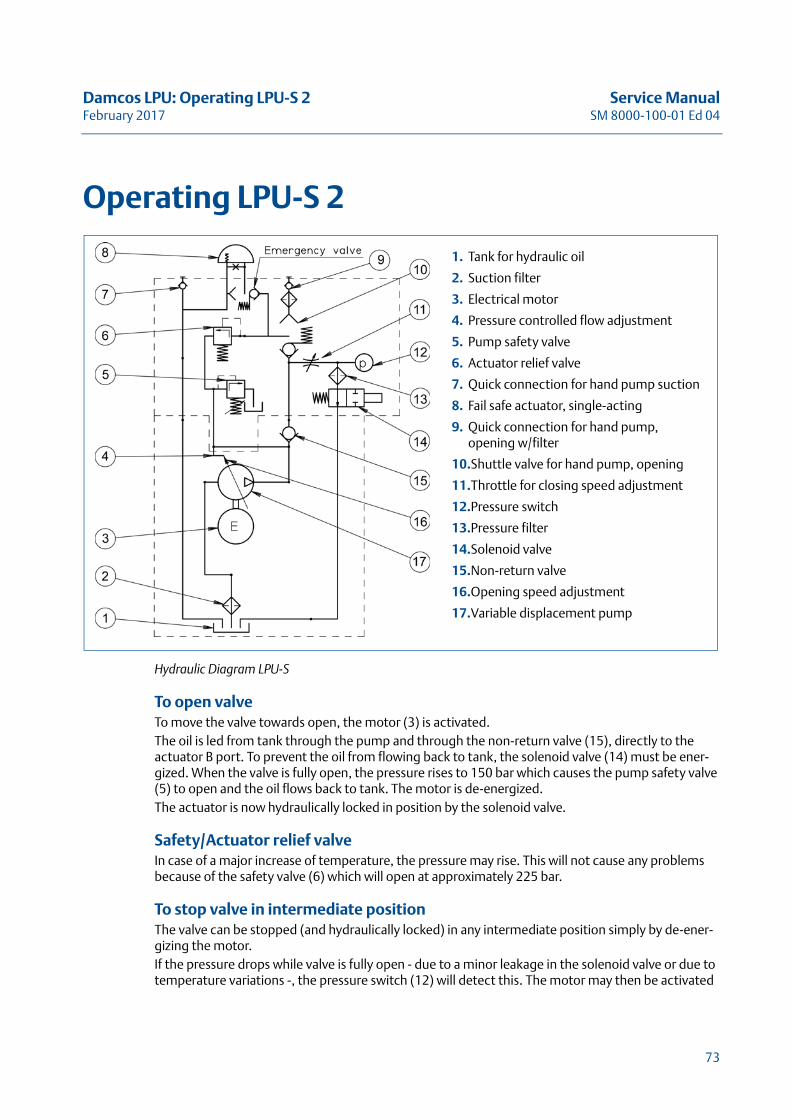
Operating LPU-S 2
Hydraulic Diagram LPU-S
To open valveTo move the valve towards open, the motor (3) is activated. The oil is led from tank through the pump and through the non-return valve (15), directly to the actuator B port. To prevent the oil from flowing back to tank, the solenoid valve (14) must be ener-gized. When the valve is fully open, the pressure rises to 150 bar which causes the pump safety valve (5) to open and the oil flows back to tank. The motor is de-energized. The actuator is now hydraulically locked in position by the solenoid valve.
Safety/Actuator relief valveIn case of a major increase of temperature, the pressure may rise. This will not cause any problems because of the safety valve (6) which will open at approximately 225 bar.
To stop valve in intermediate positionThe valve can be stopped (and hydraulically locked) in any intermediate position simply by de-ener-gizing the motor.If the pressure drops while valve is fully open - due to a minor leakage in the solenoid valve or due to temperature variations -, the pressure switch (12) will detect this. The motor may then be activated
1. Tank for hydraulic oil
2. Suction filter
3. Electrical motor
4. Pressure controlled flow adjustment
5. Pump safety valve
6. Actuator relief valve
7. Quick connection for hand pump suction
8. Fail safe actuator, single-acting
9. Quick connection for hand pump, opening w/filter
10.Shuttle valve for hand pump, opening
11.Throttle for closing speed adjustment
12.Pressure switch
13.Pressure filter
14.Solenoid valve
15.Non-return valve
16.Opening speed adjustment
17.Variable displacement pump
73
Service Manual Damcos LPU: Operating LPU-S 2SM 8000-100-01 Ed 04 February 2017
for some seconds in order to keep up the pressure, and prevent the valve from leaving the open posi-tion. - This may take place automatically.
Close valveTo move the valve towards closed, the solenoid valve is de-energized. The springs then move the actuator, pressing the oil back from the actuator B port, through the throttle valve (11) and the sole-noid valve (14) to the LPU tank.
Note! For power controlled LPU please see also “Operation LPU-S” on page 123.
74
Damcos LPU: Operating LPU-D 2a Service ManualFebruary 2017 SM 8000-100-01 Ed 04
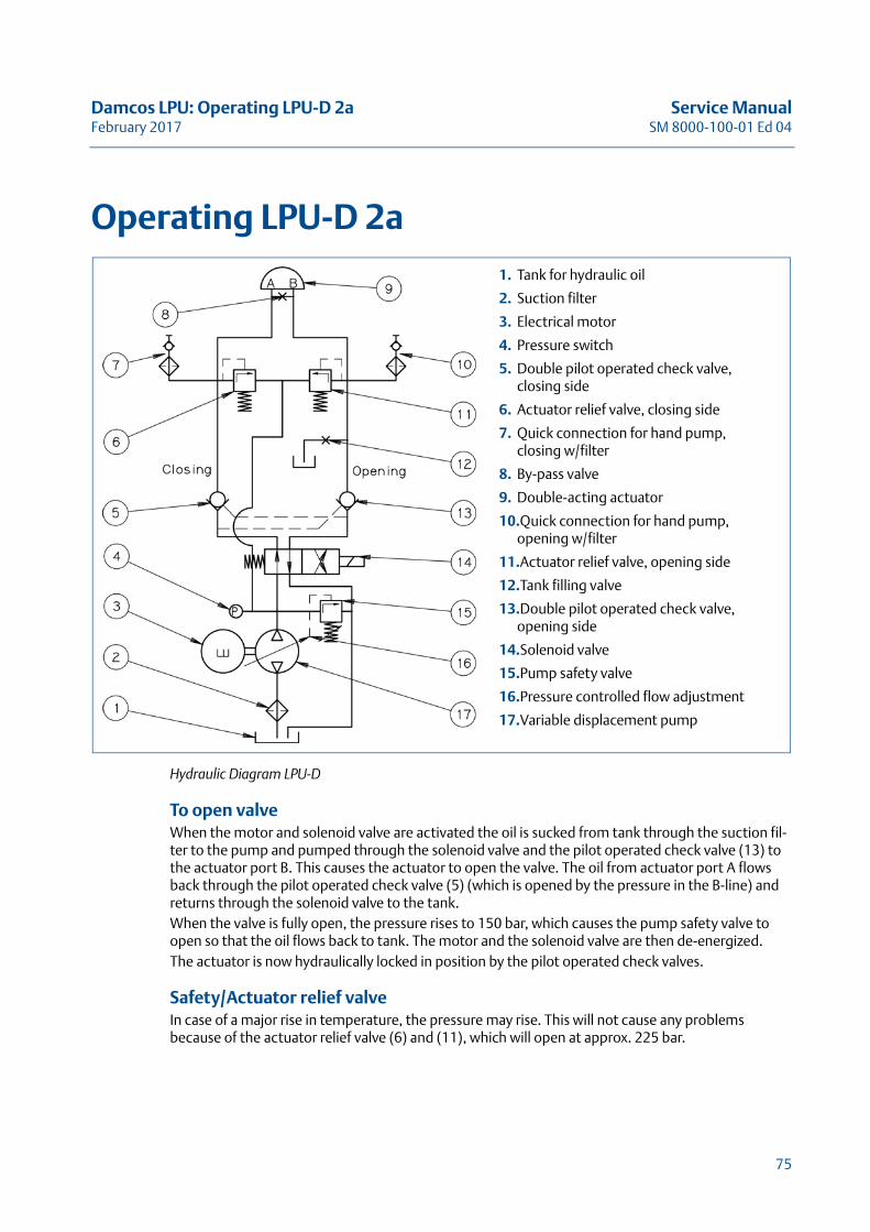
Operating LPU-D 2a
Hydraulic Diagram LPU-D
To open valveWhen the motor and solenoid valve are activated the oil is sucked from tank through the suction fil-ter to the pump and pumped through the solenoid valve and the pilot operated check valve (13) to the actuator port B. This causes the actuator to open the valve. The oil from actuator port A flows back through the pilot operated check valve (5) (which is opened by the pressure in the B-line) and returns through the solenoid valve to the tank. When the valve is fully open, the pressure rises to 150 bar, which causes the pump safety valve to open so that the oil flows back to tank. The motor and the solenoid valve are then de-energized.The actuator is now hydraulically locked in position by the pilot operated check valves.
Safety/Actuator relief valveIn case of a major rise in temperature, the pressure may rise. This will not cause any problems because of the actuator relief valve (6) and (11), which will open at approx. 225 bar.
1. Tank for hydraulic oil
2. Suction filter
3. Electrical motor
4. Pressure switch
5. Double pilot operated check valve, closing side
6. Actuator relief valve, closing side
7. Quick connection for hand pump, closing w/filter
8. By-pass valve
9. Double-acting actuator
10.Quick connection for hand pump, opening w/filter
11.Actuator relief valve, opening side
12.Tank filling valve
13.Double pilot operated check valve, opening side
14.Solenoid valve
15.Pump safety valve
16.Pressure controlled flow adjustment
17.Variable displacement pump
75
Service Manual Damcos LPU: Operating LPU-D 2aSM 8000-100-01 Ed 04 February 2017
Close valveClosing the valve follows exact the same procedure, except that the solenoid valve is not activated which causes the ports A and B to be reversed.When the motor is running the direction of oil- flow is solely determined by the activation of the sole-noid valve.
Note! For power controlled LPU please see also “Operating LPU-D” on page 124.
76
Damcos LPU: Emergency Operation of LPU V.2 Service ManualFebruary 2017 SM 8000-100-01 Ed 04
Emergency Operation of LPU V.2For all operations: When the hand pump is disconnected and the by-pass valve is closed, the remote control is allowed to operate the system again.
Note! For LPUv.2 emergency operation with hydraulic hand pump, a hand pump unit with reser-voir can be used. To avoid overfilling of the LPU, both quick connections have to be mounted.
Note! To close emergency opened actuator by remote, open the actuator first to release shuttle valve and then close.
LPU with LED Position IndicatorLPU (except Ex version) with IP 68 LED indicator will show clear red or green light when the valve is closed respectively open.
77
Service Manual Damcos LPU: Emergency Operation of LPU V.2SM 8000-100-01 Ed 04 February 2017
Firmly mounted hand pumpWith a firmly mounted hand pump the following applies:
Emergency open a fail-open LPU1. Open by-pass at the actuator or at the firmly mounted hand pump until the valve has reached
the desired position. Then close by-pass valve again.2. If the actuator has been closed by remote control and power is still on “the keep closed” function
is activated and the LPU may start up trying to keep the actuator closed. You have to disconnect power or remove close-command before manual operation is started.
The valve will now stay in position until operated with hand pump again or by remote control.
Emergency closing a fail-close actuator1. Open by-pass at the actuator or at the firmly mounted hand pump until the valve has reached
the desired position. Then close by-pass valve again.2. If the actuator has been opened by remote control and power is still on, “the keep open” func-
tion is activated and the LPU may start up trying to keep the actuator open. You have to discon-nect power or remove open-command before manual operation is started.
The valve will now stay in position until operated with hand pump again or by remote control.
Emergency closing a fail-open LPUorEmergency opening of actuator
1. Turn the directional valve at the hand pump to position “OPEN”2. Operate hand pump until the valve has reached the desired position.
The valve will now stay in position until operated with hand pump again or by remote control.
Emergency closing of a double acting actuator1. Turn the directional valve at the hand pump to position “CLOSE”2. Operate hand pump until the valve has reached the desired position.
The valve will now stay in position until operated with hand pump again or by remote control.
78
Damcos LPU: Emergency Operation of LPU V.2 Service ManualFebruary 2017 SM 8000-100-01 Ed 04
LPU-D
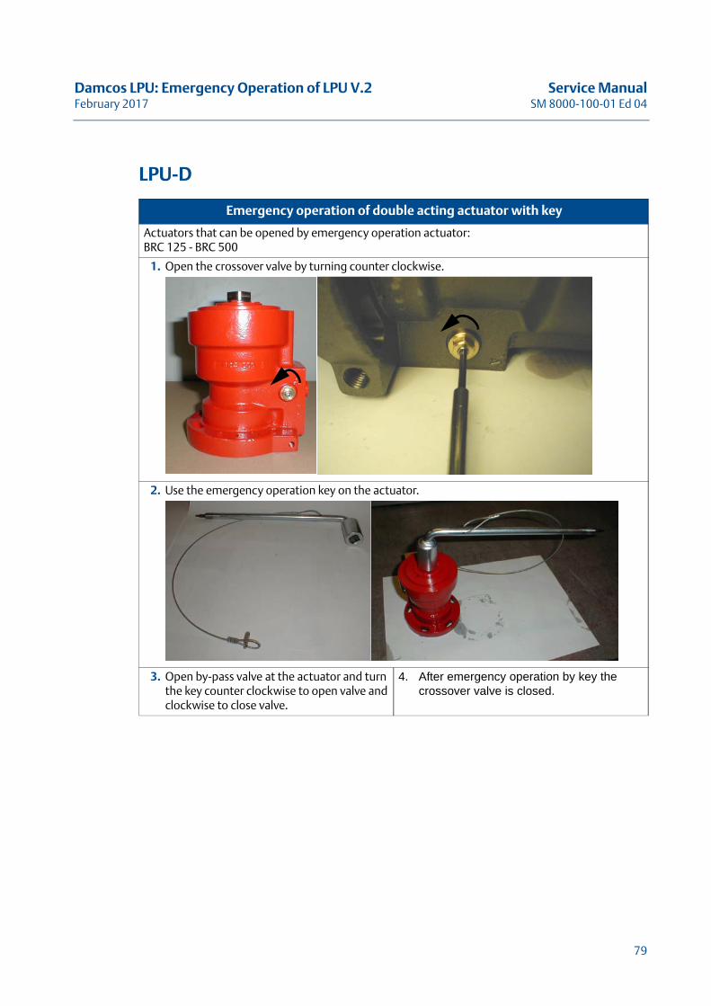
Emergency operation of double acting actuator with key
Actuators that can be opened by emergency operation actuator:BRC 125 - BRC 500
1. Open the crossover valve by turning counter clockwise.
2. Use the emergency operation key on the actuator.
3. Open by-pass valve at the actuator and turn the key counter clockwise to open valve and clockwise to close valve.
4. After emergency operation by key the crossover valve is closed.
79
Service Manual Damcos LPU: Emergency Operation of LPU V.2SM 8000-100-01 Ed 04 February 2017
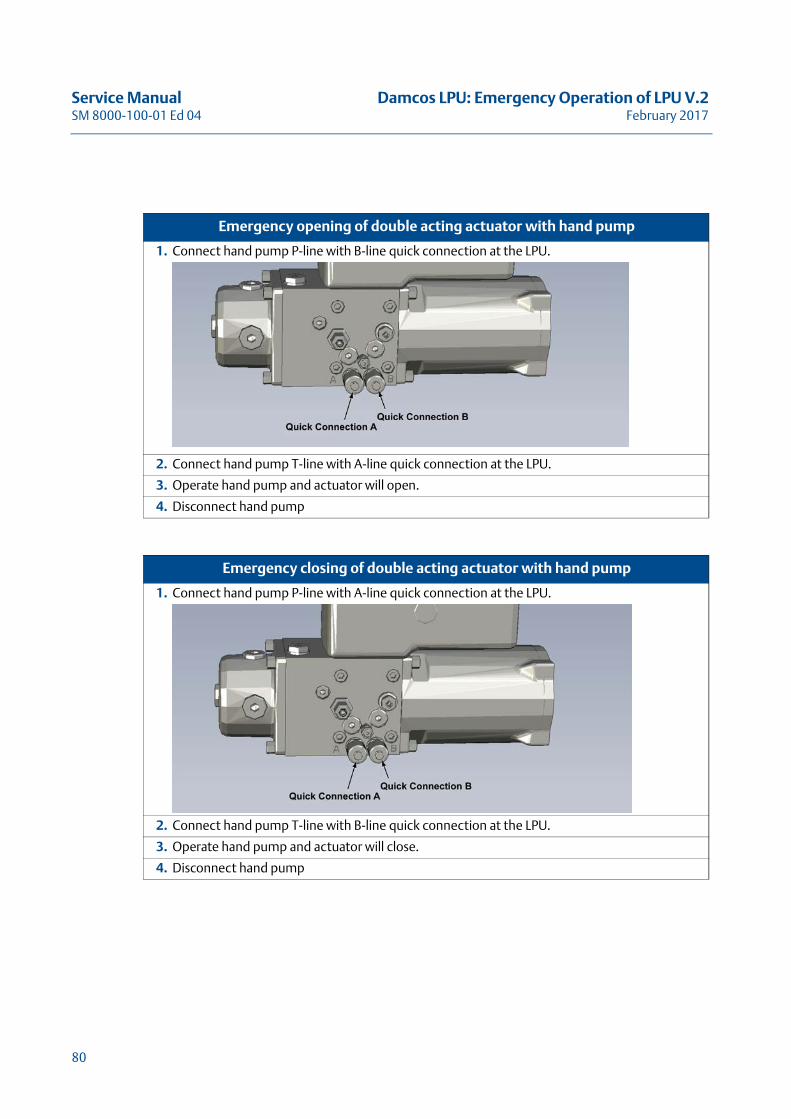
Emergency opening of double acting actuator with hand pump
1. Connect hand pump P-line with B-line quick connection at the LPU.
2. Connect hand pump T-line with A-line quick connection at the LPU.
3. Operate hand pump and actuator will open.
4. Disconnect hand pump
Emergency closing of double acting actuator with hand pump
1. Connect hand pump P-line with A-line quick connection at the LPU.
2. Connect hand pump T-line with B-line quick connection at the LPU.
3. Operate hand pump and actuator will close.
4. Disconnect hand pump
80

Damcos LPU: Emergency Operation of LPU V.2 Service ManualFebruary 2017 SM 8000-100-01 Ed 04
LPU-S
Note! This procedure applies to fail-close actuators.For Fail-open actuators please contact Emerson Process Management.
Emergency opening of single acting actuator with hand pump
1. Connect hand pump P-line with B-line quick connection at the LPU.
2. Connect hand pump T-line with T-line quick connection at the LPU.With suction to T and pressure to B the shuttle valve will change over and prevents the oil from flowing to tank.
3. Operate hand pump and actuator will open.
4. Disconnect hand pump
Emergency closing of single acting fail-close actuator
1. Open cross-over valve on actuator and let it stay open until the required position is reached.
2. When the valve is fully closed, the shuttle valve will be reset.
Emergency opening of single acting fail-open actuator
1. Open cross-over valve on actuator and let it stay open until the required position is reached.
2. When the valve is fully closed, the shuttle valve will be reset.
81
Service Manual Damcos LPU: Emergency Operation of LPU V.2SM 8000-100-01 Ed 04 February 2017
82
Damcos LPU: Speed adjustment for Actuator on LPU (v.2) Service ManualFebruary 2017 SM 8000-100-01 Ed 04
Speed adjustment for Actuator on LPU (v.2)
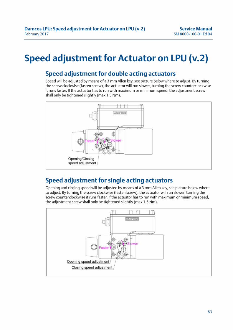
Speed adjustment for double acting actuatorsSpeed will be adjusted by means of a 3 mm Allen key, see picture below where to adjust. By turning the screw clockwise (fasten screw), the actuator will run slower, turning the screw counterclockwise it runs faster. If the actuator has to run with maximum or minimum speed, the adjustment screw shall only be tightened slightly (max 1.5 Nm).
Speed adjustment for single acting actuatorsOpening and closing speed will be adjusted by means of a 3 mm Allen key, see picture below where to adjust. By turning the screw clockwise (fasten screw), the actuator will run slower, turning the screw counterclockwise it runs faster. If the actuator has to run with maximum or minimum speed, the adjustment screw shall only be tightened slightly (max 1.5 Nm).
83
Service Manual Damcos LPU: Speed adjustment for Actuator on LPU (v.2)SM 8000-100-01 Ed 04 February 2017
84
Damcos LPU: Pump pressure adjustment for LPU Service ManualFebruary 2017 SM 8000-100-01 Ed 04
Pump pressure adjustment for LPU
Warning! Parts inside housing of LPU are connected to 230 Volts, please do not touch these parts without power supply securely OFF.
1. The pressure gauge is mounted on quick connection B (nearest to the motor) of the LPU. For LPU-D the adjustment can also be carried out with the pressure gauge on quick connection A, and thus the LPU shall only receive a ”Close”-command during adjustment.
2. Adjustment of the pump pressure is carried out with a 5 mm Allen key with ball head. The adjust-ment screw is placed near the pressure switch (the one near the LPU-front in LPU-D).
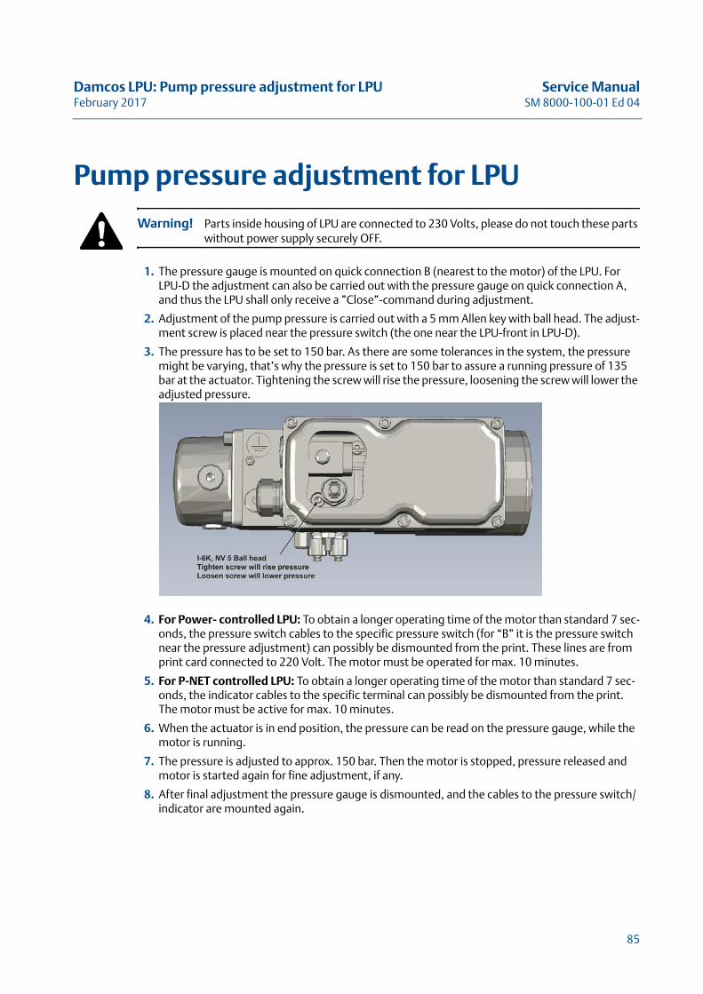
3. The pressure has to be set to 150 bar. As there are some tolerances in the system, the pressure might be varying, that’s why the pressure is set to 150 bar to assure a running pressure of 135 bar at the actuator. Tightening the screw will rise the pressure, loosening the screw will lower the adjusted pressure.
4. For Power- controlled LPU: To obtain a longer operating time of the motor than standard 7 sec-onds, the pressure switch cables to the specific pressure switch (for “B” it is the pressure switch near the pressure adjustment) can possibly be dismounted from the print. These lines are from print card connected to 220 Volt. The motor must be operated for max. 10 minutes.
5. For P-NET controlled LPU: To obtain a longer operating time of the motor than standard 7 sec-onds, the indicator cables to the specific terminal can possibly be dismounted from the print. The motor must be active for max. 10 minutes.
6. When the actuator is in end position, the pressure can be read on the pressure gauge, while the motor is running.
7. The pressure is adjusted to approx. 150 bar. Then the motor is stopped, pressure released and motor is started again for fine adjustment, if any.
8. After final adjustment the pressure gauge is dismounted, and the cables to the pressure switch/indicator are mounted again.
85
Service Manual Damcos LPU: Pump pressure adjustment for LPUSM 8000-100-01 Ed 04 February 2017
86
Damcos LPU: Refill of Oil in LPU Service ManualFebruary 2017 SM 8000-100-01 Ed 04
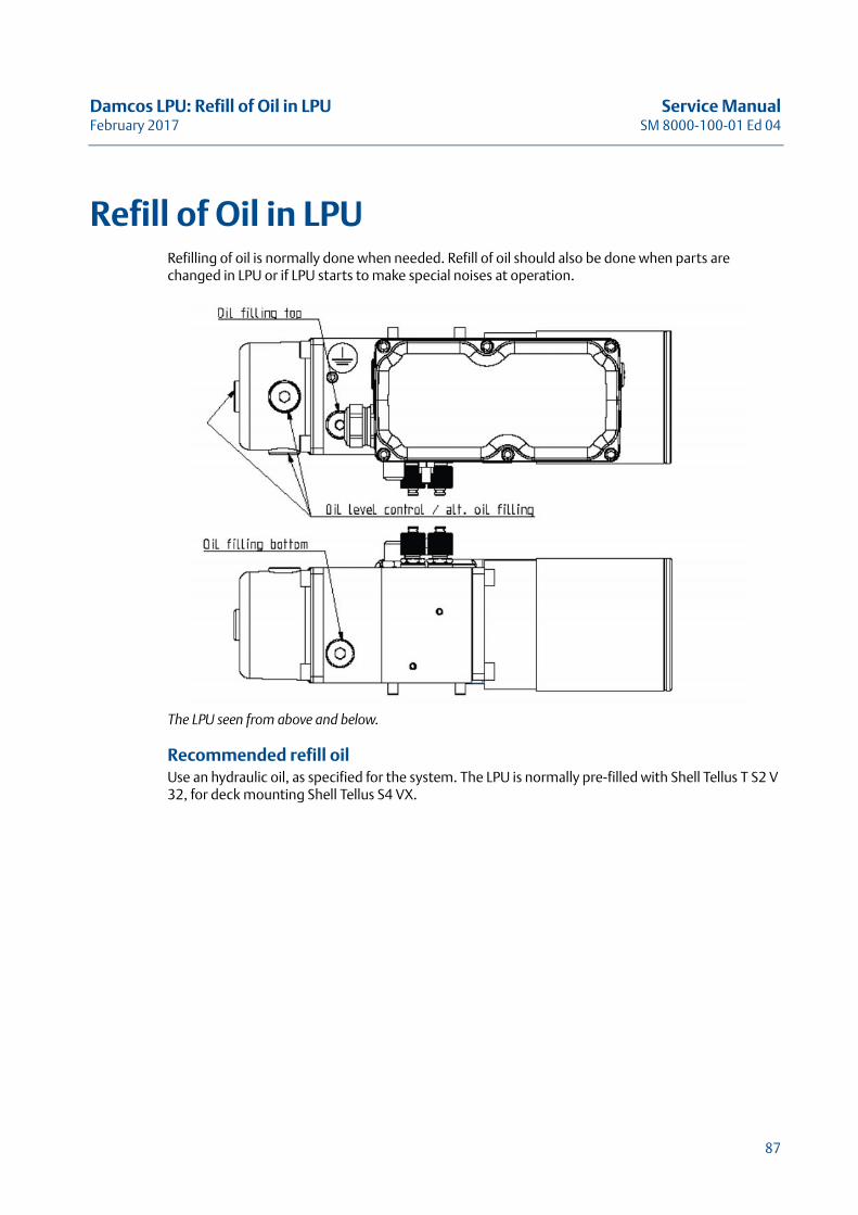
Refill of Oil in LPURefilling of oil is normally done when needed. Refill of oil should also be done when parts are changed in LPU or if LPU starts to make special noises at operation.
The LPU seen from above and below.
Recommended refill oil Use an hydraulic oil, as specified for the system. The LPU is normally pre-filled with Shell Tellus T S2 V 32, for deck mounting Shell Tellus S4 VX.
87
Service Manual Damcos LPU: Refill of Oil in LPUSM 8000-100-01 Ed 04 February 2017
Procedures
LPU without pressurised reservoir using direct level control 1. Remove the breather valve, placed on top or bottom of the LPU or end of oil tank, depending on
the LPU mounting direction, see picture on page 87. For LPU-S on BRCF the breather valve might be placed on top of BRCF.
2. Oil level must be max 15 mm below breather valve or plug in LPU. For LPU-S on BRCF oil level in LPU tank must be above suction pipe at fully opened actuator.
3. If oil level is low, fill the reservoir with hydraulic oil as specified for the system. Oil filling may be done directly through the hole for breather valve or with a hand pump.
4. LPU-S hand pump filling: Apply pressure from hand pump directly to T-quick connection of the LPU. See “LPU-S mounted on BRCF oil filling with hand pump” on page 90alt.LPU-D hand pump filling: Open stop valve at front of LPU and apply pressure from hand pump directly to B-quick connection. Close stop valve after filling. See “LPU-D Oil Filling Instruction with hand pump” on page 91.
5. Remount the breather valve.
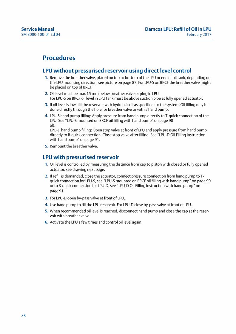
LPU with pressurised reservoir1. Oil level is controlled by measuring the distance from cap to piston with closed or fully opened
actuator, see drawing next page.
2. If refill is demanded, close the actuator, connect pressure connection from hand pump to T-quick connection for LPU-S, see “LPU-S mounted on BRCF oil filling with hand pump” on page 90 or to B-quick connection for LPU-D, see “LPU-D Oil Filling Instruction with hand pump” on page 91.
3. For LPU-D open by-pass valve at front of LPU.
4. Use hand pump to fill the LPU reservoir. For LPU-D close by-pass valve at front of LPU.
5. When recommended oil level is reached, disconnect hand pump and close the cap at the reser-voir with breather valve.
6. Activate the LPU a few times and control oil level again.
88
Damcos LPU: Refill of Oil in LPU Service ManualFebruary 2017 SM 8000-100-01 Ed 04
LPU with permanently mounted hand pumpIf the LPU is mounted with a permanently mounted hand pump, the oil level control has to be done in the LPU and in the hand pump, as malfunction is possible in an empty hand pump.
89
Service Manual Damcos LPU: Refill of Oil in LPUSM 8000-100-01 Ed 04 February 2017
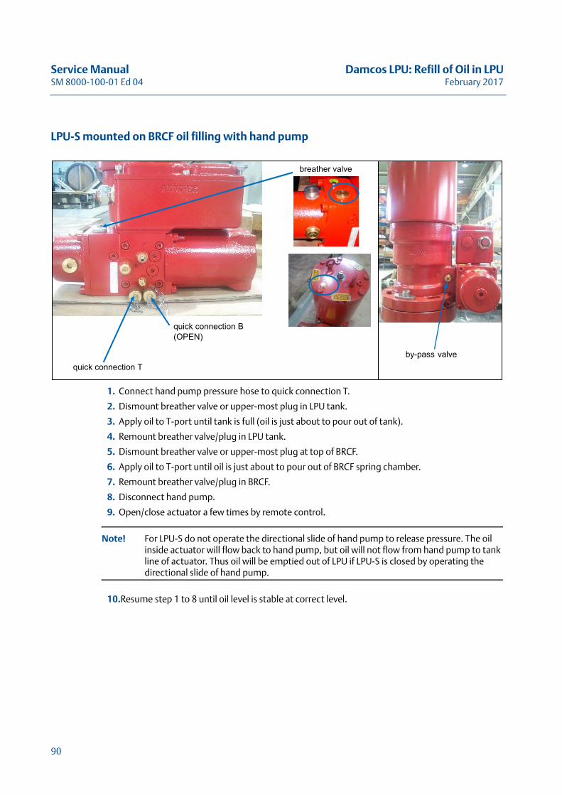
LPU-S mounted on BRCF oil filling with hand pump
1. Connect hand pump pressure hose to quick connection T.
2. Dismount breather valve or upper-most plug in LPU tank.
3. Apply oil to T-port until tank is full (oil is just about to pour out of tank).
4. Remount breather valve/plug in LPU tank.
5. Dismount breather valve or upper-most plug at top of BRCF.
6. Apply oil to T-port until oil is just about to pour out of BRCF spring chamber.
7. Remount breather valve/plug in BRCF.
8. Disconnect hand pump.
9. Open/close actuator a few times by remote control.
Note! For LPU-S do not operate the directional slide of hand pump to release pressure. The oil inside actuator will flow back to hand pump, but oil will not flow from hand pump to tank line of actuator. Thus oil will be emptied out of LPU if LPU-S is closed by operating the directional slide of hand pump.
10.Resume step 1 to 8 until oil level is stable at correct level.
breather valve
quick connection B(OPEN)
quick connection Tby-pass valve
90
Damcos LPU: Refill of Oil in LPU Service ManualFebruary 2017 SM 8000-100-01 Ed 04
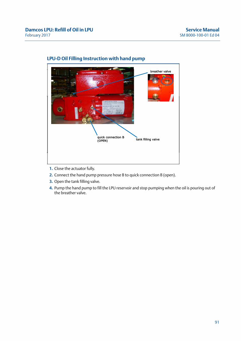
LPU-D Oil Filling Instruction with hand pump
1. Close the actuator fully.
2. Connect the hand pump pressure hose B to quick connection B (open).
3. Open the tank filling valve.
4. Pump the hand pump to fill the LPU reservoir and stop pumping when the oil is pouring out of the breather valve.
breather valve
tank filling valvequick connection B(OPEN)
breather valve
tank filling valvequick connection B(OPEN)
91
Service Manual Damcos LPU: Refill of Oil in LPUSM 8000-100-01 Ed 04 February 2017
92
Damcos LPU: Replace Pump in LPU Service ManualFebruary 2017 SM 8000-100-01 Ed 04
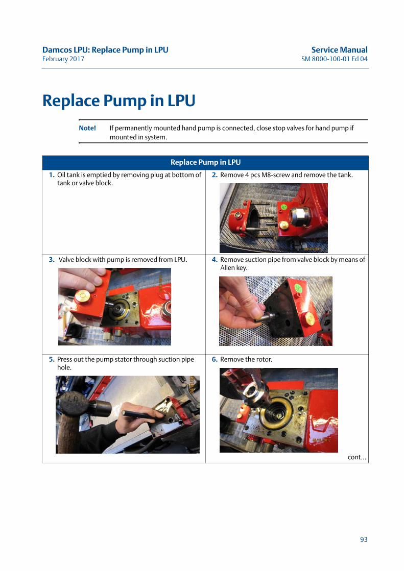
Replace Pump in LPU
Note! If permanently mounted hand pump is connected, close stop valves for hand pump if mounted in system.
Replace Pump in LPU
1. Oil tank is emptied by removing plug at bottom of tank or valve block.
2. Remove 4 pcs M8-screw and remove the tank.
3. Valve block with pump is removed from LPU. 4. Remove suction pipe from valve block by means of Allen key.
5. Press out the pump stator through suction pipe hole.
6. Remove the rotor.
cont...
93
Service Manual Damcos LPU: Replace Pump in LPUSM 8000-100-01 Ed 04 February 2017
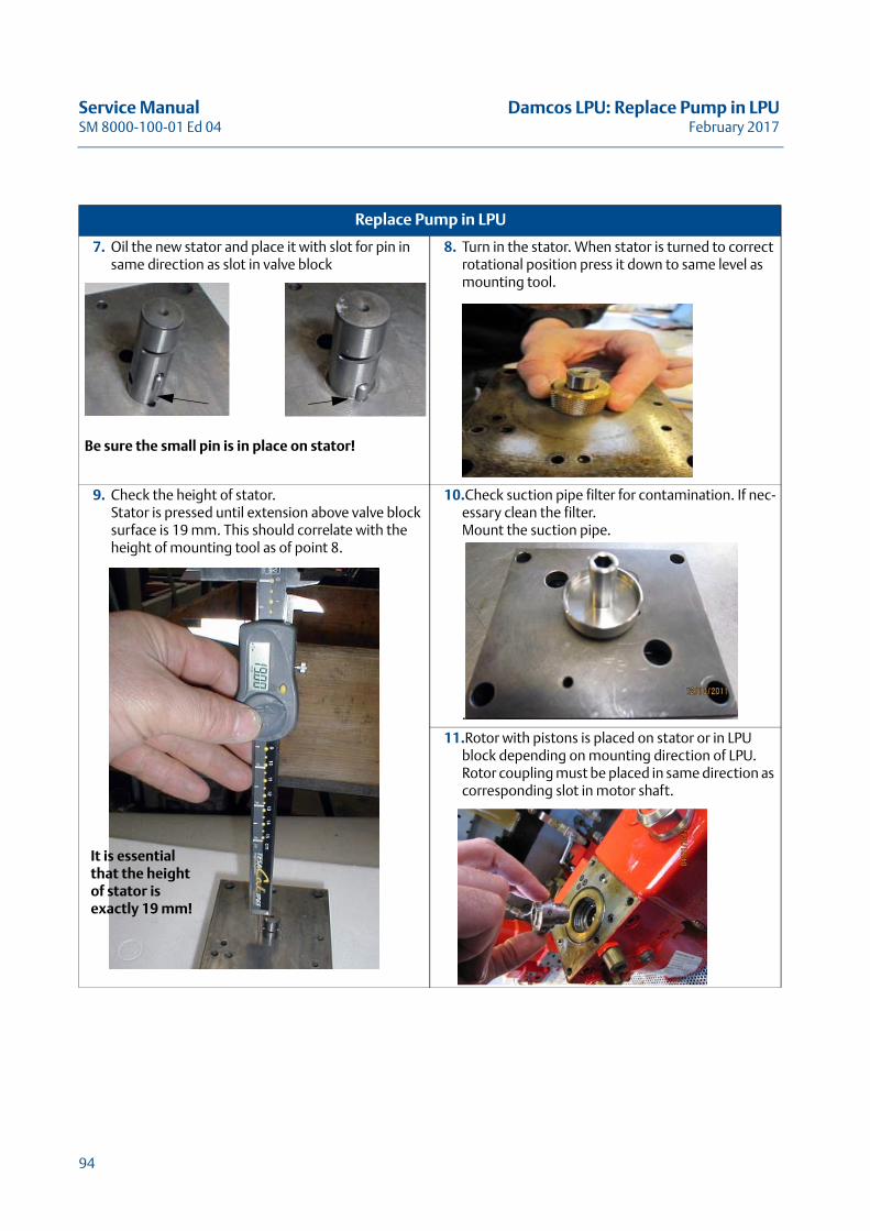
7. Oil the new stator and place it with slot for pin in same direction as slot in valve block
Be sure the small pin is in place on stator!
8. Turn in the stator. When stator is turned to correct rotational position press it down to same level as mounting tool.
9. Check the height of stator.Stator is pressed until extension above valve block surface is 19 mm. This should correlate with the height of mounting tool as of point 8.
10.Check suction pipe filter for contamination. If nec-essary clean the filter.Mount the suction pipe.
.
11.Rotor with pistons is placed on stator or in LPU block depending on mounting direction of LPU. Rotor coupling must be placed in same direction as corresponding slot in motor shaft.
Replace Pump in LPU
It is essential that the height of stator is exactly 19 mm!
94
Damcos LPU: Replace Pump in LPU Service ManualFebruary 2017 SM 8000-100-01 Ed 04
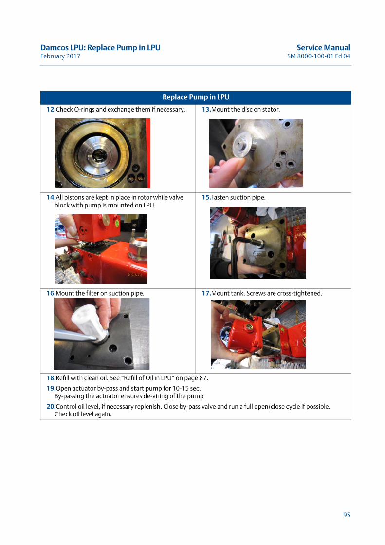
12.Check O-rings and exchange them if necessary. 13.Mount the disc on stator.
14.All pistons are kept in place in rotor while valve block with pump is mounted on LPU.
15.Fasten suction pipe.
16.Mount the filter on suction pipe. 17.Mount tank. Screws are cross-tightened.
18.Refill with clean oil. See “Refill of Oil in LPU” on page 87.
19.Open actuator by-pass and start pump for 10-15 sec. By-passing the actuator ensures de-airing of the pump
20.Control oil level, if necessary replenish. Close by-pass valve and run a full open/close cycle if possible. Check oil level again.
Replace Pump in LPU
95

Service Manual Damcos LPU: Replace Pump in LPUSM 8000-100-01 Ed 04 February 2017
96
Damcos LPU: Replace DPCV in LPU Service ManualFebruary 2017 SM 8000-100-01 Ed 04
Replace DPCV in LPUReplace DPCV in LPU
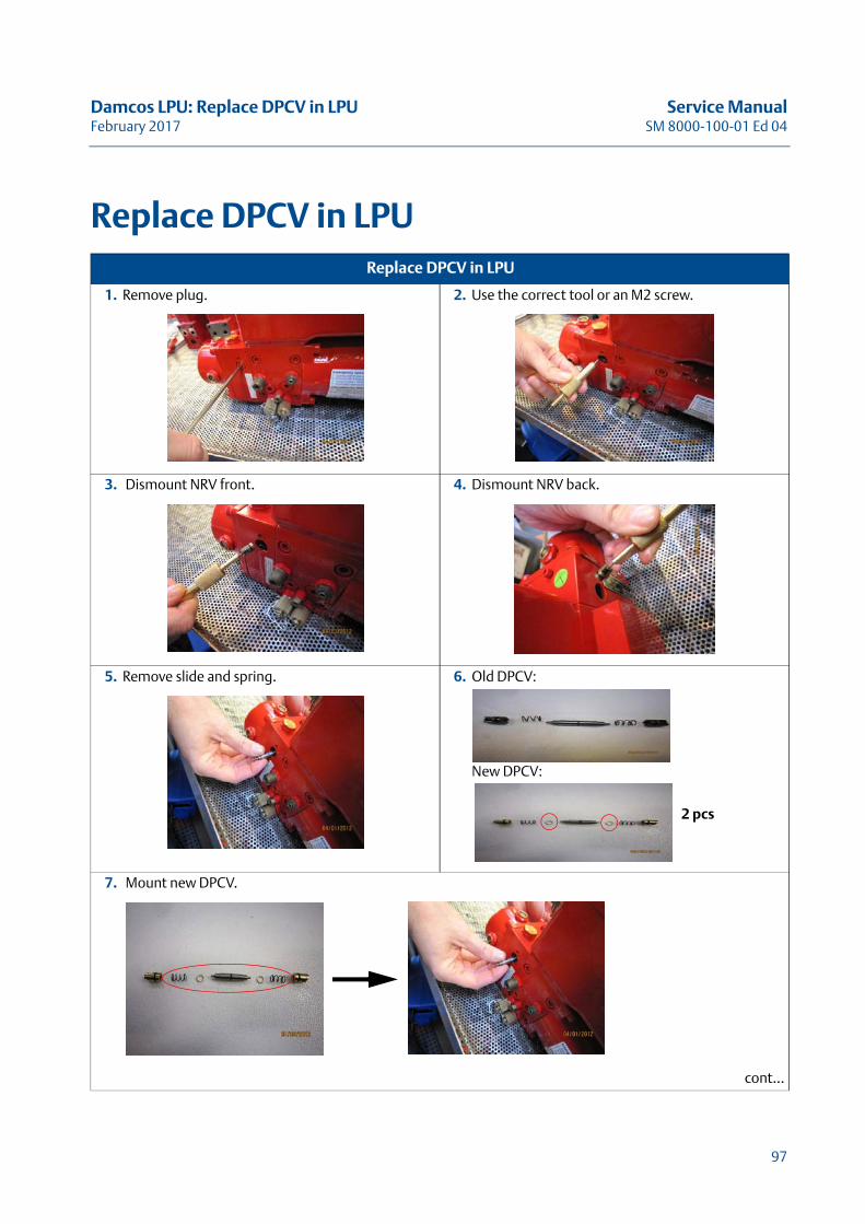
1. Remove plug. 2. Use the correct tool or an M2 screw.
3. Dismount NRV front. 4. Dismount NRV back.
5. Remove slide and spring. 6. Old DPCV:
New DPCV:
7. Mount new DPCV.
cont...
2 pcs
97
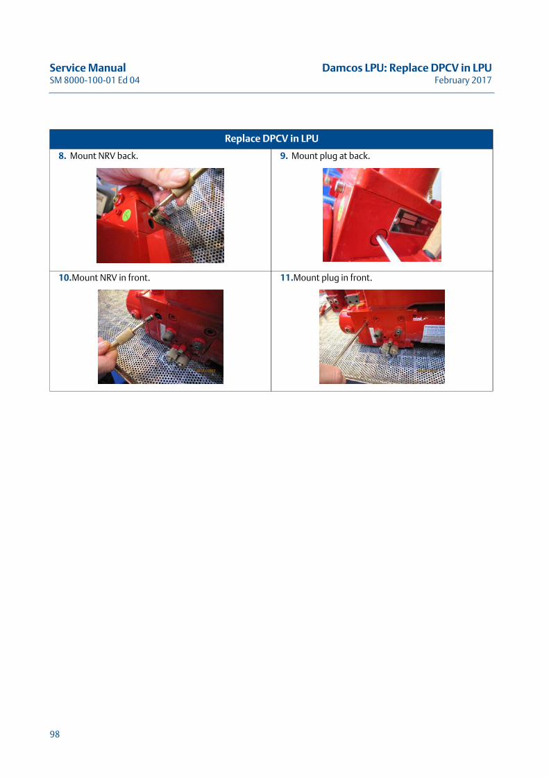
Service Manual Damcos LPU: Replace DPCV in LPUSM 8000-100-01 Ed 04 February 2017
8. Mount NRV back. 9. Mount plug at back.
10.Mount NRV in front. 11.Mount plug in front.
Replace DPCV in LPU
98
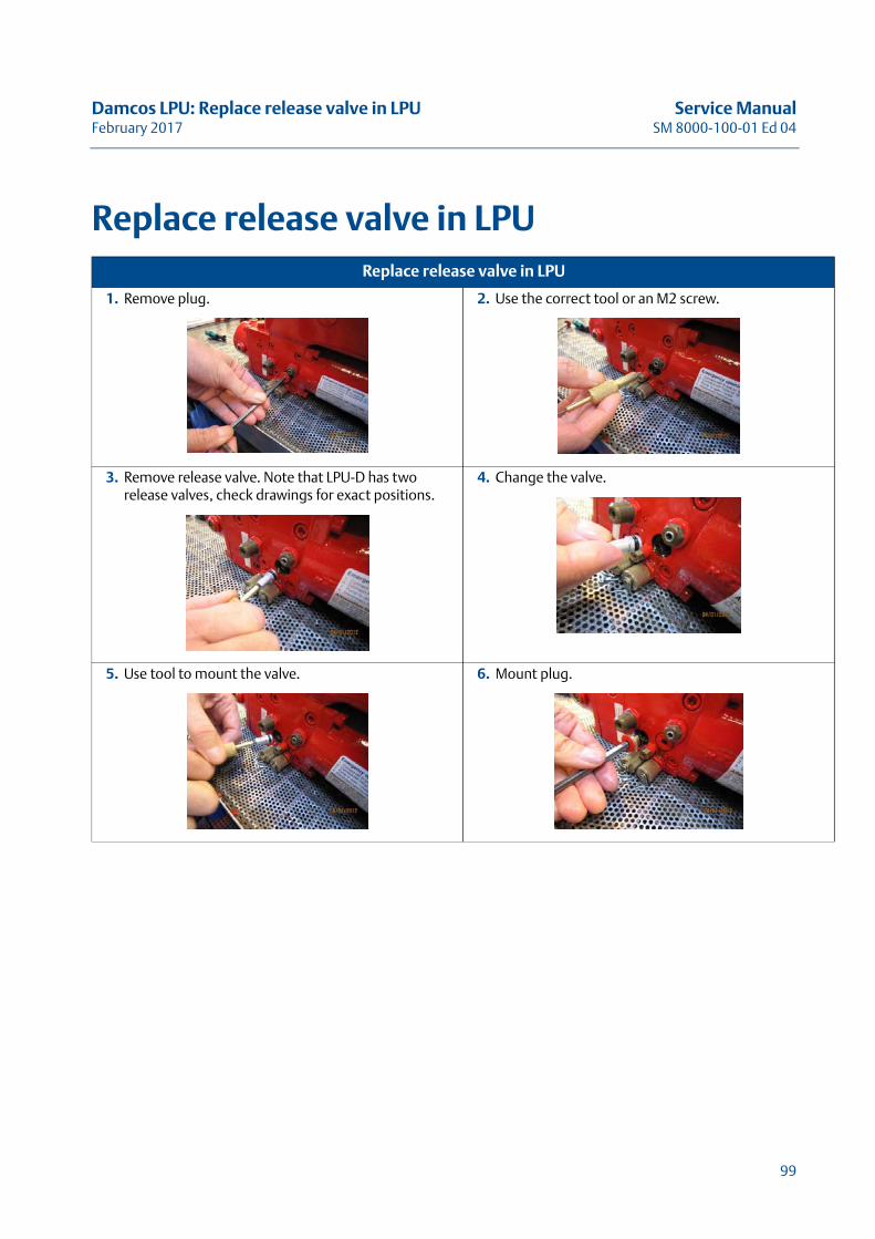
Damcos LPU: Replace release valve in LPU Service ManualFebruary 2017 SM 8000-100-01 Ed 04
Replace release valve in LPUReplace release valve in LPU
1. Remove plug. 2. Use the correct tool or an M2 screw.
3. Remove release valve. Note that LPU-D has two release valves, check drawings for exact positions.
4. Change the valve.
5. Use tool to mount the valve. 6. Mount plug.
99

Service Manual Damcos LPU: Replace release valve in LPUSM 8000-100-01 Ed 04 February 2017
100
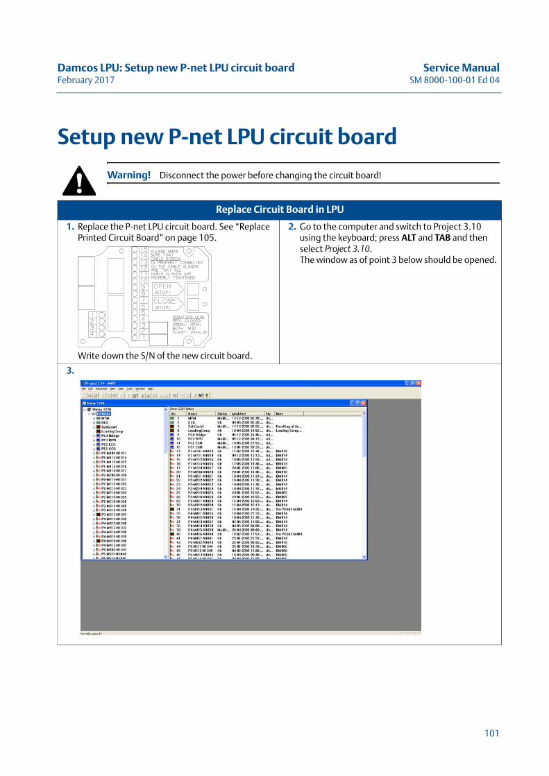
Damcos LPU: Setup new P-net LPU circuit board Service ManualFebruary 2017 SM 8000-100-01 Ed 04
Setup new P-net LPU circuit board
Warning! Disconnect the power before changing the circuit board!
Replace Circuit Board in LPU
1. Replace the P-net LPU circuit board. See “Replace Printed Circuit Board” on page 105.
Write down the S/N of the new circuit board.
2. Go to the computer and switch to Project 3.10 using the keyboard; press ALT and TAB and then select Project 3.10.The window as of point 3 below should be opened.
3.
101
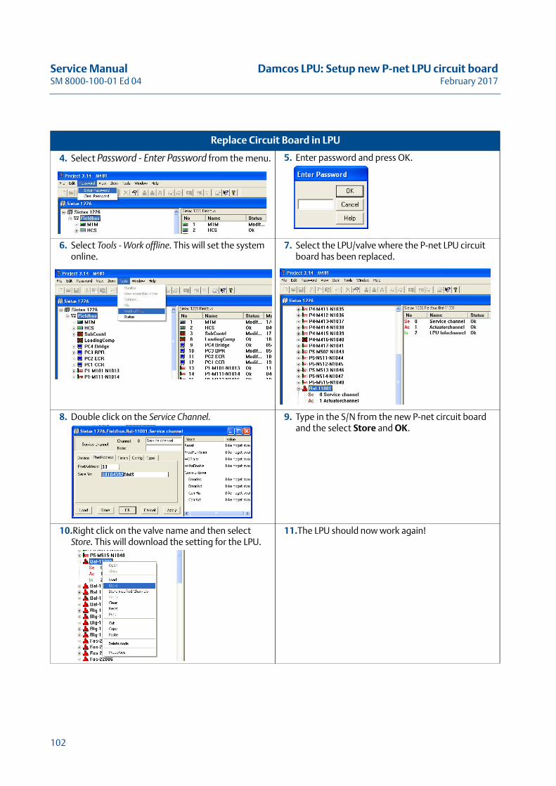
Service Manual Damcos LPU: Setup new P-net LPU circuit boardSM 8000-100-01 Ed 04 February 2017
4. Select Password - Enter Password from the menu.
5. Enter password and press OK.
6. Select Tools - Work offline. This will set the system online.
7. Select the LPU/valve where the P-net LPU circuit board has been replaced.
8. Double click on the Service Channel. 9. Type in the S/N from the new P-net circuit board and the select Store and OK.
10.Right click on the valve name and then select Store. This will download the setting for the LPU.
11.The LPU should now work again!
Replace Circuit Board in LPU
102
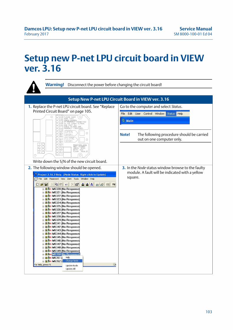
Damcos LPU: Setup new P-net LPU circuit board in VIEW ver. 3.16 Service ManualFebruary 2017 SM 8000-100-01 Ed 04
Setup new P-net LPU circuit board in VIEW ver. 3.16
Warning! Disconnect the power before changing the circuit board!
Setup New P-net LPU Circuit Board in VIEW ver. 3.16
1. Replace the P-net LPU circuit board. See “Replace Printed Circuit Board” on page 105.
Write down the S/N of the new circuit board.
Go to the computer and select Status.
Note! The following procedure should be carried out on one computer only.
2. The following window should be opened. 3. In the Node status window browse to the faulty module. A fault will be indicated with a yellow square.
103
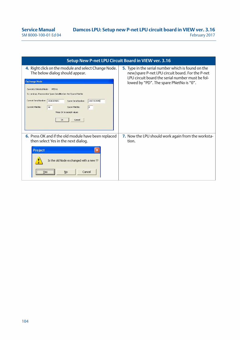
Service Manual Damcos LPU: Setup new P-net LPU circuit board in VIEW ver. 3.16SM 8000-100-01 Ed 04 February 2017
4. Right click on the module and select Change Node. The below dialog should appear.
5. Type in the serial number which is found on the new/spare P-net LPU circuit board. For the P-net LPU circuit board the serial number must be fol-lowed by “PD”. The spare PNetNo is “0”.
6. Press OK and if the old module have been replaced then select Yes in the next dialog.
7. Now the LPU should work again from the worksta-tion.
Setup New P-net LPU Circuit Board in VIEW ver. 3.16
104
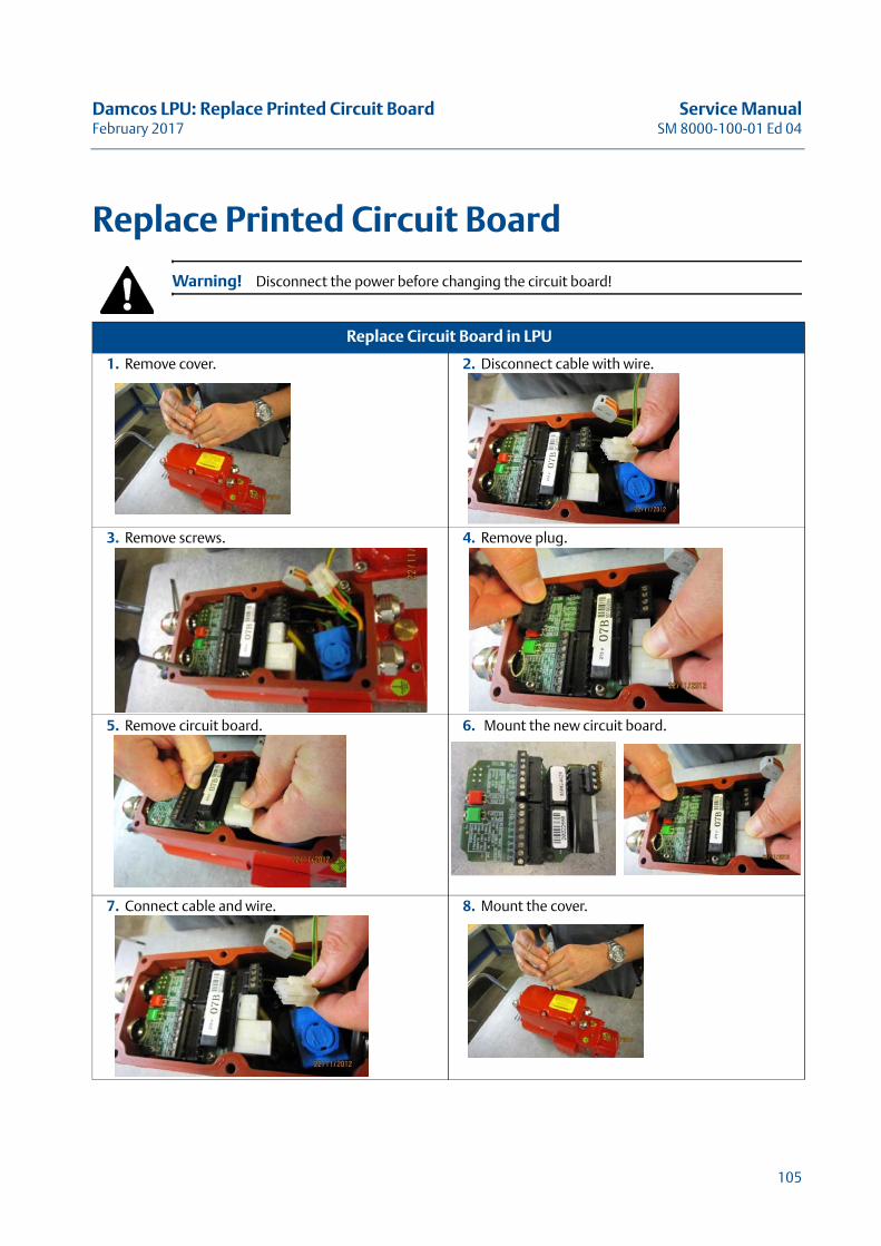
Damcos LPU: Replace Printed Circuit Board Service ManualFebruary 2017 SM 8000-100-01 Ed 04
Replace Printed Circuit Board
Warning! Disconnect the power before changing the circuit board!
Replace Circuit Board in LPU
1. Remove cover. 2. Disconnect cable with wire.
3. Remove screws. 4. Remove plug.
5. Remove circuit board. 6. Mount the new circuit board.
7. Connect cable and wire. 8. Mount the cover.
105

Service Manual Damcos LPU: Replace Printed Circuit BoardSM 8000-100-01 Ed 04 February 2017
106
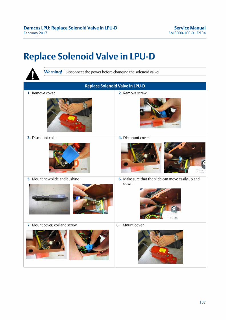
Damcos LPU: Replace Solenoid Valve in LPU-D Service ManualFebruary 2017 SM 8000-100-01 Ed 04
Replace Solenoid Valve in LPU-D
Warning! Disconnect the power before changing the solenoid valve!
Replace Solenoid Valve in LPU-D
1. Remove cover. 2. Remove screw.
3. Dismount coil. 4. Dismount cover.
5. Mount new slide and bushing. 6. Make sure that the slide can move easily up and down.
7. Mount cover, coil and screw. 8. Mount cover.
107

Service Manual Damcos LPU: Replace Solenoid Valve in LPU-DSM 8000-100-01 Ed 04 February 2017
108
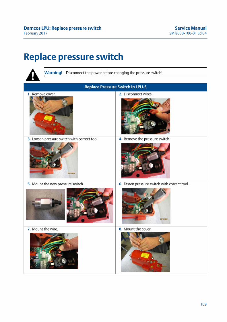
Damcos LPU: Replace pressure switch Service ManualFebruary 2017 SM 8000-100-01 Ed 04
Replace pressure switch
Warning! Disconnect the power before changing the pressure switch!
Replace Pressure Switch in LPU-S
1. Remove cover. 2. Disconnect wires.
3. Loosen pressure switch with correct tool. 4. Remove the pressure switch.
5. Mount the new pressure switch. 6. Fasten pressure switch with correct tool.
7. Mount the wire. 8. Mount the cover.
109

Service Manual Damcos LPU: Replace pressure switchSM 8000-100-01 Ed 04 February 2017
110
Damcos LPU: LPU Technical Data Service ManualFebruary 2017 SM 8000-100-01 Ed 04
LPU Technical DataThis Chapter Describes the Local Power Unit
with Technical Data
111

Service Manual Damcos LPU: LPU Technical DataSM 8000-100-01 Ed 04 February 2017
112
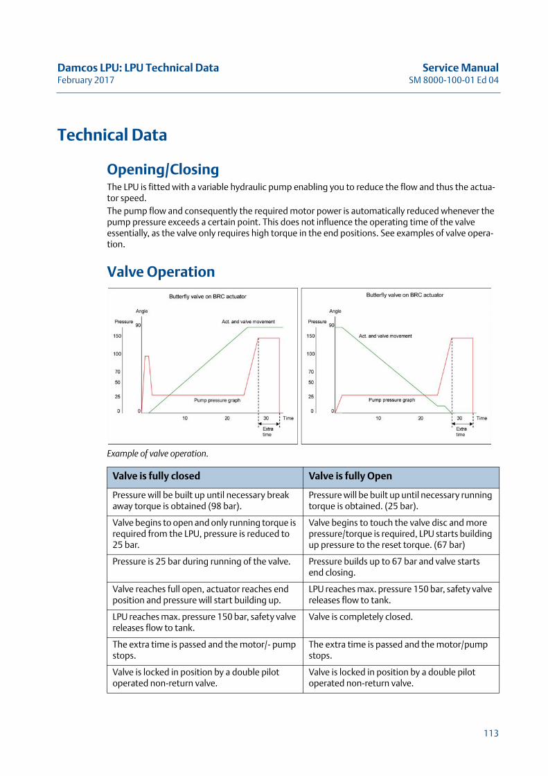
Damcos LPU: LPU Technical Data Service ManualFebruary 2017 SM 8000-100-01 Ed 04
Technical Data
Opening/ClosingThe LPU is fitted with a variable hydraulic pump enabling you to reduce the flow and thus the actua-tor speed.The pump flow and consequently the required motor power is automatically reduced whenever the pump pressure exceeds a certain point. This does not influence the operating time of the valve essentially, as the valve only requires high torque in the end positions. See examples of valve opera-tion.
Valve Operation
Example of valve operation.
Valve is fully closed Valve is fully Open
Pressure will be built up until necessary break away torque is obtained (98 bar).
Pressure will be built up until necessary running torque is obtained. (25 bar).
Valve begins to open and only running torque is required from the LPU, pressure is reduced to 25 bar.
Valve begins to touch the valve disc and more pressure/torque is required, LPU starts building up pressure to the reset torque. (67 bar)
Pressure is 25 bar during running of the valve. Pressure builds up to 67 bar and valve starts end closing.
Valve reaches full open, actuator reaches end position and pressure will start building up.
LPU reaches max. pressure 150 bar, safety valve releases flow to tank.
LPU reaches max. pressure 150 bar, safety valve releases flow to tank.
Valve is completely closed.
The extra time is passed and the motor/- pump stops.
The extra time is passed and the motor/pump stops.
Valve is locked in position by a double pilot operated non-return valve.
Valve is locked in position by a double pilot operated non-return valve.
113
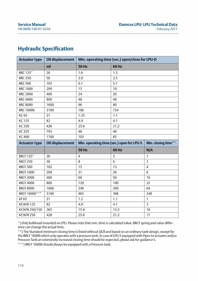
Service Manual Damcos LPU: LPU Technical DataSM 8000-100-01 Ed 04 February 2017
Hydraulic Specification
*) Only bulkhead mounted on LPU. Please note that min. time is calculated value. BRCF spring and value differ-ence can change the actual time.**) The Standard minimum closing time is listed without QCB and based on an ordinary tank design, except for the BRCF 16000 which only operates with a pressure tank. In case of LPU-S equipped with Pipes to actuator and/or Pressure Tank an extensively increased closing time should be expected, please ask for guidance’s.***) BRCF 16000 should always be equipped with a Pressure tank.
Actuator type Oil displacement Min. operating time (sec.) open/close for LPU-D
ml 50 Hz 60 Hz
BRC 125* 26 1.6 1.3
BRC 250 50 3.0 2.5
BRC 500 102 6.1 5.1
BRC 1000 209 13 10
BRC 2000 400 24 20
BRC 4000 800 48 40
BRC 8000 1600 96 80
BRC 16000 3100 186 154
KC 65 21 1.35 1.1
KC 125 82 4.9 4.1
KC 250 428 25.6 21.2
KC 325 793 48 40
KC 400 1700 102 85
Actuator type Oil displacement Min. operating time (sec.) open for LPU-S Min. closing time**
50 Hz 60 Hz N/A
BRCF 125* 26 4 3 1
BRCF 250 50 8 6 2
BRCF 500 102 15 13 4
BRCF 1000 209 31 26 8
BRCF 2000 400 60 50 16
BRCF 4000 800 120 100 32
BRCF 8000 1600 240 200 64
BRCF 16000*** 3100 465 388 248
KF 65 21 1.2 1.1 1
KF/KFR 125 82 4.9 4.1 3
KF/KFR 250/150 265 15.9 13.2 10
KF/KFR 250 428 25.6 21.2 17
114
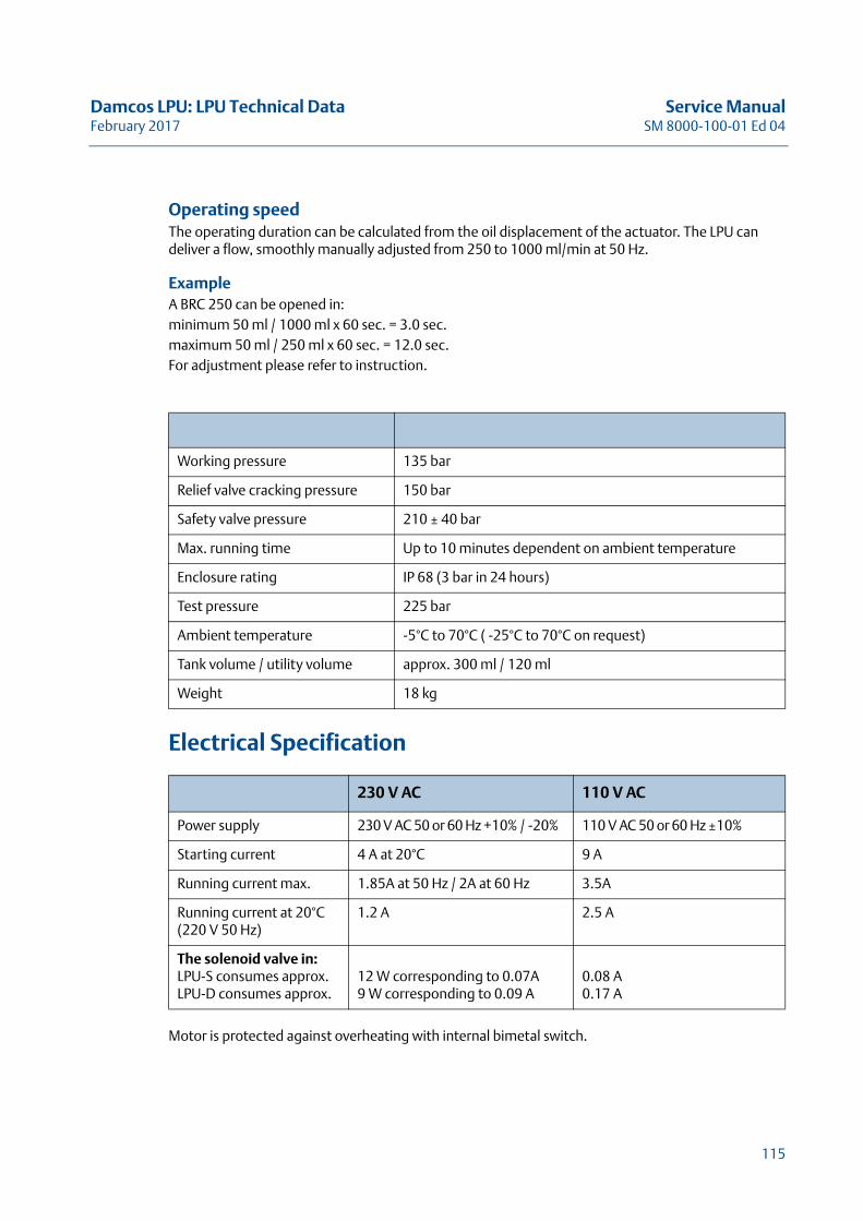
Damcos LPU: LPU Technical Data Service ManualFebruary 2017 SM 8000-100-01 Ed 04
Operating speedThe operating duration can be calculated from the oil displacement of the actuator. The LPU can deliver a flow, smoothly manually adjusted from 250 to 1000 ml/min at 50 Hz.
ExampleA BRC 250 can be opened in:minimum 50 ml / 1000 ml x 60 sec. = 3.0 sec.maximum 50 ml / 250 ml x 60 sec. = 12.0 sec.For adjustment please refer to instruction.
Electrical Specification
Motor is protected against overheating with internal bimetal switch.
Working pressure 135 bar
Relief valve cracking pressure 150 bar
Safety valve pressure 210 ± 40 bar
Max. running time Up to 10 minutes dependent on ambient temperature
Enclosure rating IP 68 (3 bar in 24 hours)
Test pressure 225 bar
Ambient temperature -5°C to 70°C ( -25°C to 70°C on request)
Tank volume / utility volume approx. 300 ml / 120 ml
Weight 18 kg
230 V AC 110 V AC
Power supply 230 V AC 50 or 60 Hz +10% / -20% 110 V AC 50 or 60 Hz ±10%
Starting current 4 A at 20°C 9 A
Running current max. 1.85A at 50 Hz / 2A at 60 Hz 3.5A
Running current at 20°C (220 V 50 Hz)
1.2 A 2.5 A
The solenoid valve in:LPU-S consumes approx.LPU-D consumes approx.
12 W corresponding to 0.07A9 W corresponding to 0.09 A
0.08 A0.17 A
115
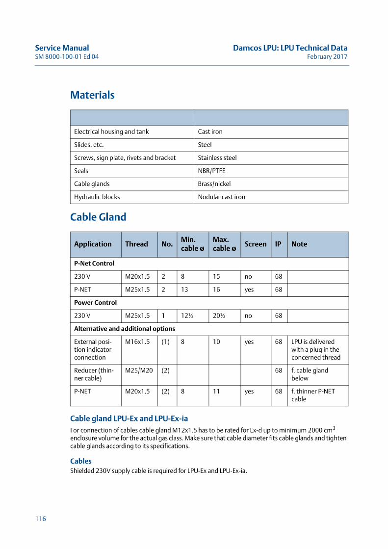
Service Manual Damcos LPU: LPU Technical DataSM 8000-100-01 Ed 04 February 2017
Materials
Cable Gland
Cable gland LPU-Ex and LPU-Ex-iaFor connection of cables cable gland M12x1.5 has to be rated for Ex-d up to minimum 2000 cm3 enclosure volume for the actual gas class. Make sure that cable diameter fits cable glands and tighten cable glands according to its specifications.
CablesShielded 230V supply cable is required for LPU-Ex and LPU-Ex-ia.
Electrical housing and tank Cast iron
Slides, etc. Steel
Screws, sign plate, rivets and bracket Stainless steel
Seals NBR/PTFE
Cable glands Brass/nickel
Hydraulic blocks Nodular cast iron
Application Thread No.Min. cable ø
Max. cable ø Screen IP Note
P-Net Control
230 V M20x1.5 2 8 15 no 68
P-NET M25x1.5 2 13 16 yes 68
Power Control
230 V M25x1.5 1 12½ 20½ no 68
Alternative and additional options
External posi-tion indicator connection
M16x1.5 (1) 8 10 yes 68 LPU is delivered with a plug in the concerned thread
Reducer (thin-ner cable)
M25/M20 (2) 68 f. cable gland below
P-NET M20x1.5 (2) 8 11 yes 68 f. thinner P-NET cable
116

Damcos LPU: LPU Technical Data Service ManualFebruary 2017 SM 8000-100-01 Ed 04
Zener barrier LPU-Ex-iaThe internal zener-barrier is built-in in the top cover and holds an Ex-d cable gland. The 24 VDC power supply to the LPU must be connected 0 to ground.
117

Service Manual Damcos LPU: LPU Technical DataSM 8000-100-01 Ed 04 February 2017
118
Damcos LPU: LPU Power Control System Service ManualFebruary 2017 SM 8000-100-01 Ed 04
LPU Power Control SystemThis Chapter describes LPU Power Control System
and Technical Data
119

Service Manual Damcos LPU: LPU Power Control SystemSM 8000-100-01 Ed 04 February 2017
120
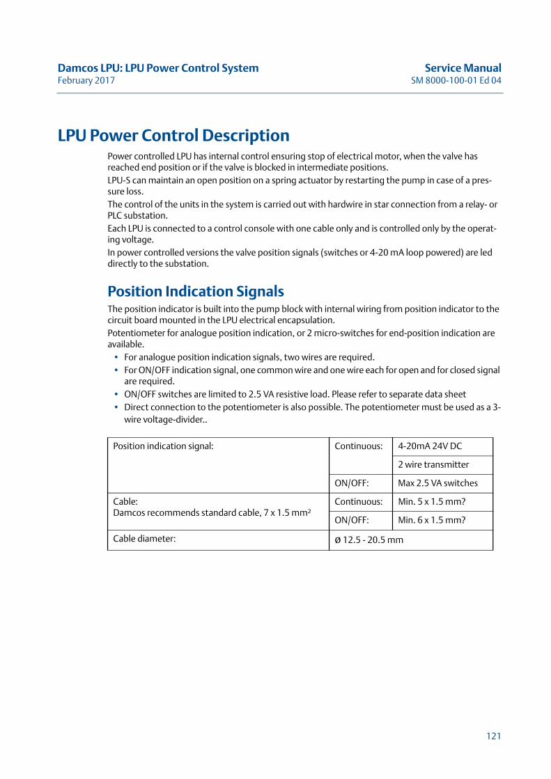
Damcos LPU: LPU Power Control System Service ManualFebruary 2017 SM 8000-100-01 Ed 04
LPU Power Control DescriptionPower controlled LPU has internal control ensuring stop of electrical motor, when the valve has reached end position or if the valve is blocked in intermediate positions.LPU-S can maintain an open position on a spring actuator by restarting the pump in case of a pres-sure loss.The control of the units in the system is carried out with hardwire in star connection from a relay- or PLC substation.Each LPU is connected to a control console with one cable only and is controlled only by the operat-ing voltage.In power controlled versions the valve position signals (switches or 4-20 mA loop powered) are led directly to the substation.
Position Indication SignalsThe position indicator is built into the pump block with internal wiring from position indicator to the circuit board mounted in the LPU electrical encapsulation.Potentiometer for analogue position indication, or 2 micro-switches for end-position indication are available.
• For analogue position indication signals, two wires are required. • For ON/OFF indication signal, one common wire and one wire each for open and for closed signal
are required. • ON/OFF switches are limited to 2.5 VA resistive load. Please refer to separate data sheet• Direct connection to the potentiometer is also possible. The potentiometer must be used as a 3-
wire voltage-divider..
Position indication signal: Continuous: 4-20mA 24V DC
2 wire transmitter
ON/OFF: Max 2.5 VA switches
Cable:Damcos recommends standard cable, 7 x 1.5 mm²
Continuous: Min. 5 x 1.5 mm?
ON/OFF: Min. 6 x 1.5 mm?
Cable diameter: ø 12.5 - 20.5 mm
121
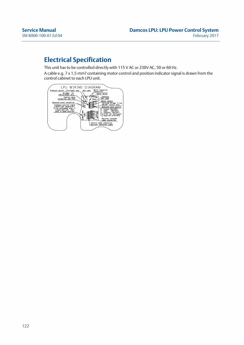
Service Manual Damcos LPU: LPU Power Control SystemSM 8000-100-01 Ed 04 February 2017
Electrical SpecificationThis unit has to be controlled directly with 115 V AC or 230V AC, 50 or 60 Hz.A cable e.g. 7 x 1,5 mm? containing motor control and position indicator signal is drawn from the control cabinet to each LPU unit.
122
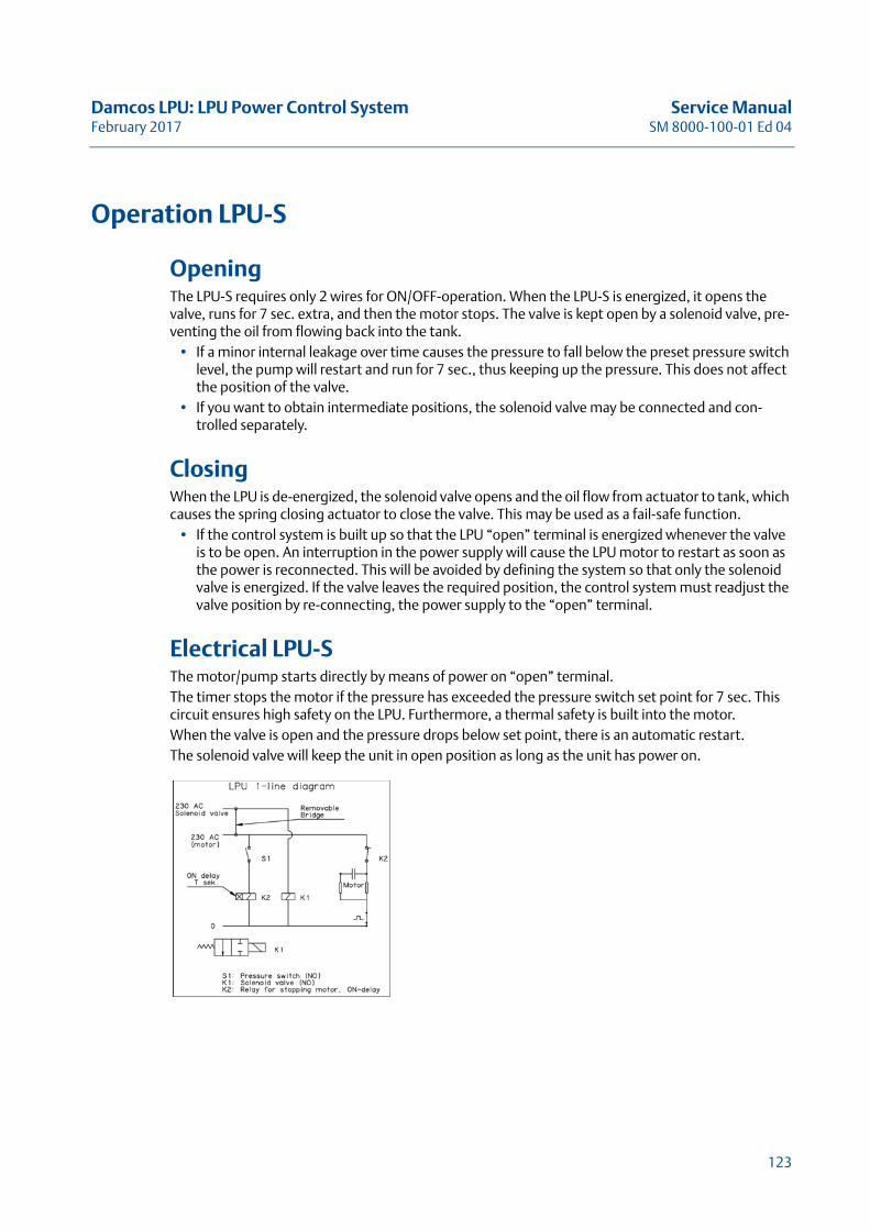
Damcos LPU: LPU Power Control System Service ManualFebruary 2017 SM 8000-100-01 Ed 04
Operation LPU-S
Opening The LPU-S requires only 2 wires for ON/OFF-operation. When the LPU-S is energized, it opens the valve, runs for 7 sec. extra, and then the motor stops. The valve is kept open by a solenoid valve, pre-venting the oil from flowing back into the tank.
• If a minor internal leakage over time causes the pressure to fall below the preset pressure switch level, the pump will restart and run for 7 sec., thus keeping up the pressure. This does not affect the position of the valve.
• If you want to obtain intermediate positions, the solenoid valve may be connected and con-trolled separately.
ClosingWhen the LPU is de-energized, the solenoid valve opens and the oil flow from actuator to tank, which causes the spring closing actuator to close the valve. This may be used as a fail-safe function.
• If the control system is built up so that the LPU “open” terminal is energized whenever the valve is to be open. An interruption in the power supply will cause the LPU motor to restart as soon as the power is reconnected. This will be avoided by defining the system so that only the solenoid valve is energized. If the valve leaves the required position, the control system must readjust the valve position by re-connecting, the power supply to the “open” terminal.
Electrical LPU-SThe motor/pump starts directly by means of power on “open” terminal.The timer stops the motor if the pressure has exceeded the pressure switch set point for 7 sec. This circuit ensures high safety on the LPU. Furthermore, a thermal safety is built into the motor.When the valve is open and the pressure drops below set point, there is an automatic restart.The solenoid valve will keep the unit in open position as long as the unit has power on.
123
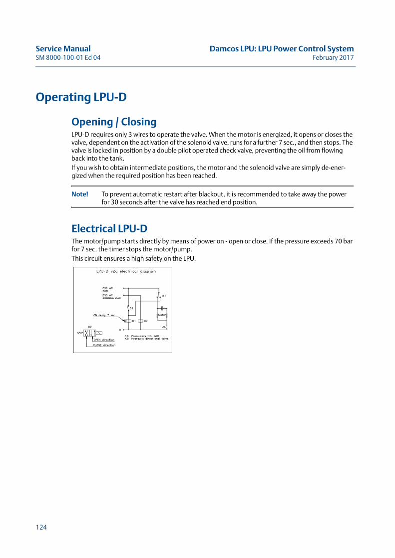
Service Manual Damcos LPU: LPU Power Control SystemSM 8000-100-01 Ed 04 February 2017
Operating LPU-D
Opening / ClosingLPU-D requires only 3 wires to operate the valve. When the motor is energized, it opens or closes the valve, dependent on the activation of the solenoid valve, runs for a further 7 sec., and then stops. The valve is locked in position by a double pilot operated check valve, preventing the oil from flowing back into the tank.If you wish to obtain intermediate positions, the motor and the solenoid valve are simply de-ener-gized when the required position has been reached.
Note! To prevent automatic restart after blackout, it is recommended to take away the power for 30 seconds after the valve has reached end position.
Electrical LPU-DThe motor/pump starts directly by means of power on - open or close. If the pressure exceeds 70 bar for 7 sec. the timer stops the motor/pump.This circuit ensures a high safety on the LPU.
124
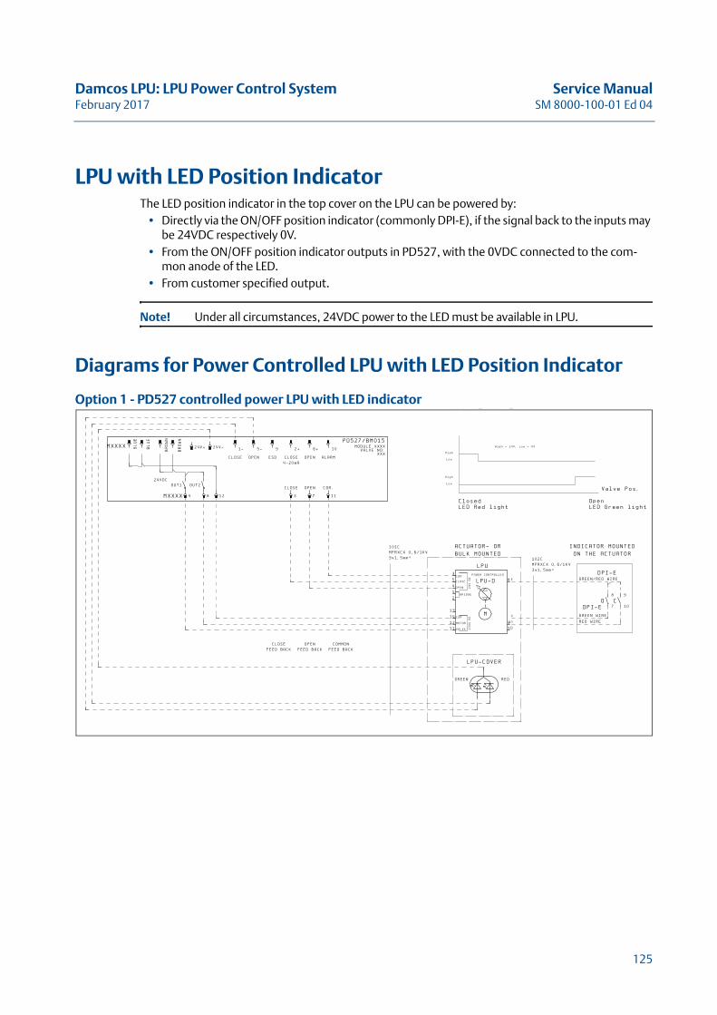
Damcos LPU: LPU Power Control System Service ManualFebruary 2017 SM 8000-100-01 Ed 04
LPU with LED Position IndicatorThe LED position indicator in the top cover on the LPU can be powered by:
• Directly via the ON/OFF position indicator (commonly DPI-E), if the signal back to the inputs may be 24VDC respectively 0V.
• From the ON/OFF position indicator outputs in PD527, with the 0VDC connected to the com-mon anode of the LED.
• From customer specified output.
Note! Under all circumstances, 24VDC power to the LED must be available in LPU.
Diagrams for Power Controlled LPU with LED Position Indicator
Option 1 - PD527 controlled power LPU with LED indicator
��(�*5/�-�(���� ������.� .�����
���
����� / ��
/ ��
��.��
/���
/���
���
����� �
��.8
���
+
��.�
��
��
� ���
(�
����
,
���
� ���
3����/��4
�8
� ���
���-!�
� ���
�
)8
����
����
*
����
3����/��4
�-
� ��
���0
��
������
3����/��4
�-��
������-9)5�4.
,:�9(!!;
�� '
$%
�� '
$%
�<$="> ���">�<� '&
����
�
��������� �����
� ���
����
�
(
�
��
��
��
���
���
.� .�
��.���
��-.���
��
/��7��
�
�-
,
+
��
��������
/� 4�������
��7���
�������
�����.�
�� '�?���.9� $%�?�-.
+
,
�-
�-��
������-9)5�4.
�:�9(!!;
7���5������
7�������
������
�����
��"� ���7�""��<� '&
�����
.�<@"��$=0
��������������
�����������
�+
*�
,
�-
125
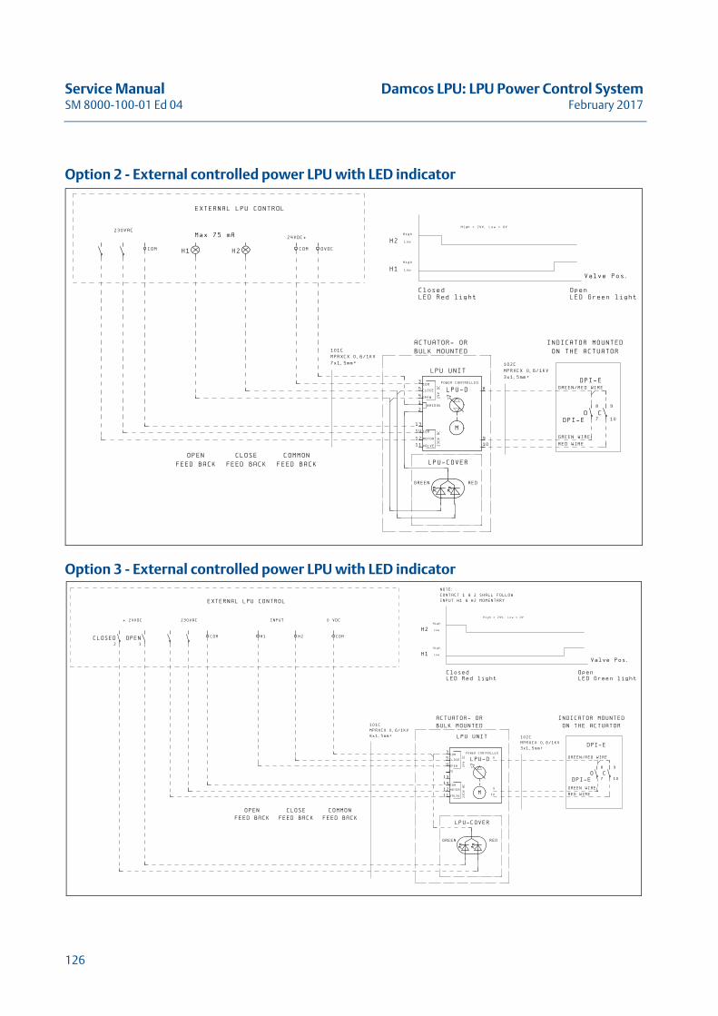
Service Manual Damcos LPU: LPU Power Control SystemSM 8000-100-01 Ed 04 February 2017
Option 2 - External controlled power LPU with LED indicator
Option 3 - External controlled power LPU with LED indicator
��-.��
���
����� � �������
��:�*(�!�
��
����
3����/��4
��
� ���
3����/��4
��.��8
���
������
3����/��4
�.��
�-��
������-9)5�4.
*:�9(!!;
��
��
�� '
$%
�� '
$%
�<$="> ���">�<� '&
����
�
��������� �����
� ���
����
�
(
�
��
��
��
���
���
.� .�
��.���
��-.���
��
/��7��
�
�-
,
+
��������
/� 4�������
��7���
������
�����.�
�� '�?���.9� $%�?�-.
�-��
������-9)5�4.
�:�9(!!;
7���5������
7�������
������
�����
��"� ���7�""��<� '&
�����
.�<@"��$=0
��������������
�����������
�+
*�
,
�-
� �����
8���.��
�����
��-.��
����� � �������
���
����
3����/��4
��
����
��
� ���
3����/��4
-�.��
���
������
3����/��4
�-��
������-9)5�4.
+:�9(!!;
��
��
�� '
$%
�� '
$%
����
��������A������ �3� ���
��������A����������2
�<$="> ���">�<� '&
����
�
��������� �����
� ���
����
�
(
�
��
��
��
��
���
���
.� .�
��.���
��-.���
��
��������
/� 4�������
��7���
������
�����.�
�� '�?���.9� $%�?�-.
+
,
�-
�-��
������-9)5�4.
�:�9(!!;
7���5������
7�������
������
�����
��"� ���7�""��<� '&
�����
.�<@"��$=0
��������������
�����������
�+
*�
,
�-
126
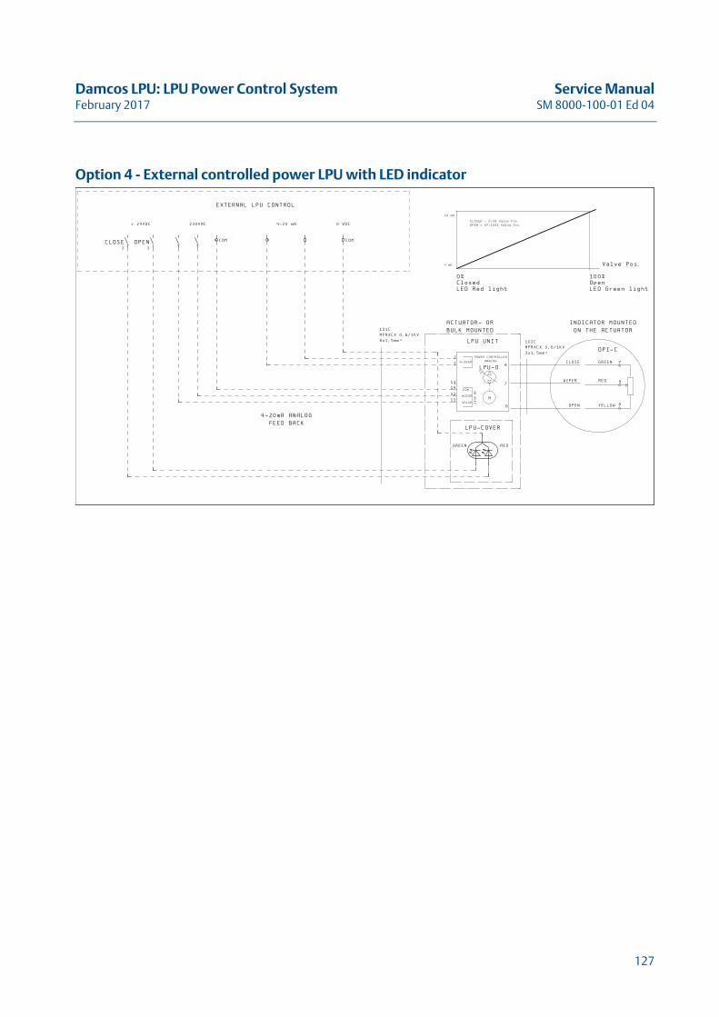
Damcos LPU: LPU Power Control System Service ManualFebruary 2017 SM 8000-100-01 Ed 04
Option 4 - External controlled power LPU with LED indicator
� ����
8���.��
�����
��-.��
����� � �������
���
���-�!�
���-!����� �7
3����/��4
-�.��
���
�-��
������-9)5�4.
+:�9(!!;
�-�!�
��!�
-B�<$="> ���">�<� '&
���-!�
���
���
.� .� ��-.���
��������� ��
��� �7
����
�
�
�
��
��
��
��
+
*
)
��������
/� 4�������
��7���
������
�����.�
� �����?�-��B�.�<@"��$=0
�����?�,*��--B�.�<@"��$=0
�-��
������-9)5�4.
�:�9(!!;
� ���
�����
����
�--B��"� ���7�""��<� '&
�����
7���
��
2� ��
.�<@"��$=0
��������������
�����������
*
,
+
127

Service Manual Damcos LPU: LPU Power Control SystemSM 8000-100-01 Ed 04 February 2017
128
Damcos LPU: LPU P-NET System Service ManualFebruary 2017 SM 8000-100-01 Ed 04
LPU P-NET SystemThis chapter describes P-NET LPU system
and Technical Data
129

Service Manual Damcos LPU: LPU P-NET SystemSM 8000-100-01 Ed 04 February 2017
130
Damcos LPU: LPU P-NET System Service ManualFebruary 2017 SM 8000-100-01 Ed 04
LPU P-Net DescriptionThe P-NET controlled LPU can be used as a stand-alone unit without being connected to P-NET. In this case it is controlled from external inputs/outputs connected to simple push buttons, lamps or e.g. a PLC (Programmable Logistic Controller).The LPU has built-in internal push-buttons and LEDs to be used for commissioning/test of the unit.Whether the LPU is controlled by the P-NET or by external inputs/outputs, the built-in microproces-sor controls and manages the actual control. This ensures an optimal control of the LPU, which is never overloaded.
Position Indication Input SignalsThe position indicator is built into the pump block with internal wiring from position indicator to the circuit board mounted in the LPU electrical encapsulation (except for KFR). Potentiometer for ana-logue position indication or 2 micro-switches for end-position indication are available.The P-NET LPU is to be configured either to position indicator type ON/OFF or analogue.
LPU with LED Position IndicatorThe LED indicator is powered from the 24VDC supply for the LPU electronics, via the internal position indicator output relays in LPU circuit board. LED indicator can be used with either ON/OFF or ANALOG position indicator as desired. With analog position indicator, the LED will change status over at 3% open valve and 97% open valve.
131
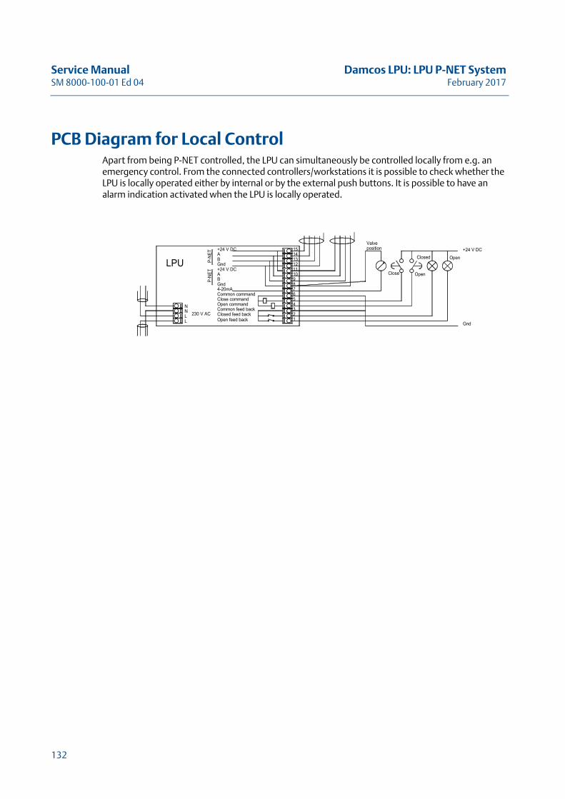
Service Manual Damcos LPU: LPU P-NET SystemSM 8000-100-01 Ed 04 February 2017
PCB Diagram for Local ControlApart from being P-NET controlled, the LPU can simultaneously be controlled locally from e.g. an emergency control. From the connected controllers/workstations it is possible to check whether the LPU is locally operated either by internal or by the external push buttons. It is possible to have an alarm indication activated when the LPU is locally operated.
LL
NN
LPU
4-20mA
Closed feed backOpen feed back
Common feed back
Common commandClose commandOpen command
230 V AC
P-NE
T
B
Gnd
P-NE
T
AB
+24 V DCGnd
A+24 V DC
Close
7
12
5
34
6
13
8
109
1112
1415
Valveposition
Gnd
Open
Closed Open+24 V DC
132
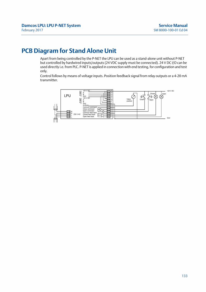
Damcos LPU: LPU P-NET System Service ManualFebruary 2017 SM 8000-100-01 Ed 04
PCB Diagram for Stand Alone UnitApart from being controlled by the P-NET the LPU can be used as a stand-alone unit without P-NET but controlled by hardwired inputs/outputs (24 VDC supply must be connected). 24 V DC I/O can be used directly i.e. from PLC. P-NET is applied in connection with end testing, for configuration and test only.Control follows by means of voltage inputs. Position feedback signal from relay outputs or a 4-20 mA transmitter.
NLL
N
LPU
Gnd
Open feed back
Common feed backClosed feed back
Common commandClose commandOpen command
230 V AC
4-20mA
P-NE
T
A
P-N
ET
B
+24 V DC
BGnd
A
+24 V DC
8
21
7
3456
Valveposition
14
10111213
9
15
Close
Gnd
OpenClosed
Open
+24 V DC
133

Service Manual Damcos LPU: LPU P-NET SystemSM 8000-100-01 Ed 04 February 2017
134
Damcos LPU: Hydraulic Hand Pump Service ManualFebruary 2017 SM 8000-100-01 Ed 04
Hydraulic Hand PumpThis Chapter Describes the Hydraulic Hand Pump
with Technical Data
135

Service Manual Damcos LPU: Hydraulic Hand PumpSM 8000-100-01 Ed 04 February 2017
136
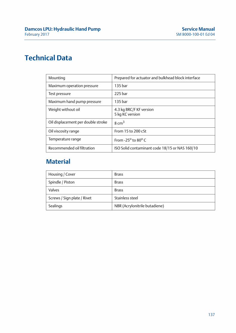
Damcos LPU: Hydraulic Hand Pump Service ManualFebruary 2017 SM 8000-100-01 Ed 04
Technical Data
Material
Mounting Prepared for actuator and bulkhead block interface
Maximum operation pressure 135 bar
Test pressure 225 bar
Maximum hand pump pressure 135 bar
Weight without oil 4.3 kg BRC/F KF version5 kg KC version
Oil displacement per double stroke 8 cm3
Oil viscosity range From 15 to 200 cSt
Temperature range From -25o to 80o C
Recommended oil filtration ISO Solid contaminant code 18/15 or NAS 160/10
Housing / Cover Brass
Spindle / Piston Brass
Valves Brass
Screws / Sign plate / Rivet Stainless steel
Sealings NBR (Acrylonitrile butadiene)
137
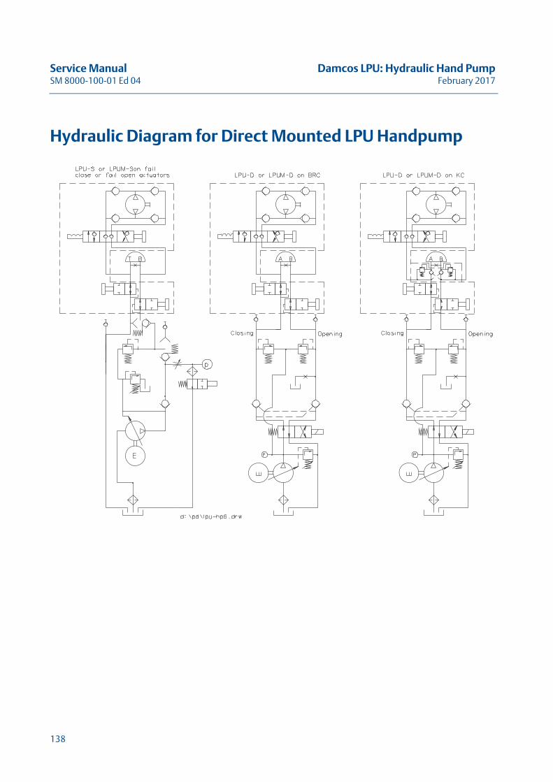
Service Manual Damcos LPU: Hydraulic Hand PumpSM 8000-100-01 Ed 04 February 2017
Hydraulic Diagram for Direct Mounted LPU Handpump
138
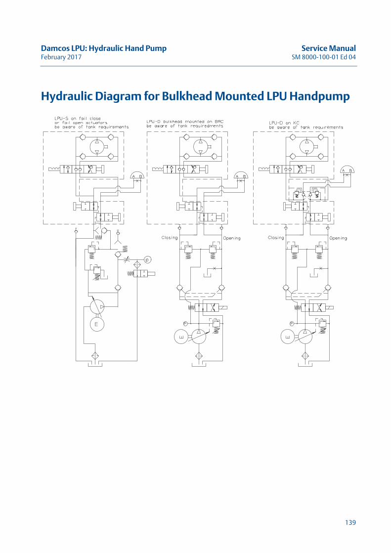
Damcos LPU: Hydraulic Hand Pump Service ManualFebruary 2017 SM 8000-100-01 Ed 04
Hydraulic Diagram for Bulkhead Mounted LPU Handpump
139

Service Manual Damcos LPU: Hydraulic Hand PumpSM 8000-100-01 Ed 04 February 2017
140
Damcos LPU: Index Service ManualFebruary 2017 SM 8000-100-01 Ed 04
IndexAActuator only running in one direction .............. 53Actuator speed adjustment on LPU ................... 83
BBleeder valve positions .................................... 14
CCheck of oil level ............................................. 88
DDPCV replacement in LPU ................................ 97
EEmergency operation
by hand pump giving oil spillage through breath-er valve........................................ 59
by hand pump not possible ........................ 60by key giving oil spillage through breather valve
59by key not possible, hydraulically locked ...... 59
Emergency Operation of LPU V.2 ...................... 77
FFault finding LPU............................................. 45Firmly mounted hand pump
Emergency operation ................................ 78
GGeneral Considerations ................................... 14
HHand pump.................................................. 137
Hydraulic Diagram .................................. 138High pressure on the port to which oil is led ....... 62Hydraulic Diagram for Bulkhead Mounted LPU Handpump .......................................................... 139Hydraulic Diagram for Direct Mounted LPU Handpump .......................................................... 138
LLED Position Indicator...................................... 16LPU
Electrical Specification............................. 115Hydraulic Specification ............................ 114
Materials ................................................ 116Mounting ................................................. 16Operating speed ..................................... 115Technical data ........................................ 113
LPU and Optional Equipment ............................ 16LPU cannot raise pressure after hand pump operation ......................................................................67LPU leaking from bleeder valve ......................... 68LPU Power Control Description ....................... 121LPU-D ............................................................ 32
Emergency operation ................................ 79LPU-D not maintaining pressure on actuator....... 57LPU-D-Ex ........................................................ 36LPU-D-Ex-ia .................................................... 40LPU-EEx has to be bulk mounted because of too littlespace or zone 0 at actuator............................... 71LPU-Ex motor do not run .................................. 70LPU-S ............................................................. 20
Emergency operation ................................ 81LPU-S frequently restarting............................... 47LPU-S-Ex......................................................... 24LPU-S-Ex-ia ..................................................... 28
MMotor ”diving” in RPM as spring actuator opens .. 63Motor ”diving” in RPM in end position................ 63Motor not running........................................... 49Motor not running on LPU-Ex ............................ 70Motor not stopping ......................................... 50Motor running for a short time and stops ........... 62Motor running hot........................................... 49
LPU is operating normally........................... 56
NNoise from pump
at both high and low pressure ..................... 55only at high pressure ................................. 55only at low pressure................................... 54
OOil and refilling instruction ............................... 87Oil in electronic connection box ........................ 64Oil in LPU........................................................ 87Oil level check................................................. 88Oil spillage from breather valve ......................... 64Oil spillage through breather valve
at emergency operation by hand pump ....... 59
141
Service Manual Damcos LPU: IndexSM 8000-100-01 Ed 04 February 2017
at emergency operation with key................ 59Oil spillage, generally ...................................... 64Operating LPU-D 2a ........................................ 75Operating LPU-S 2a ......................................... 73Operating speed........................................... 115Overview
LPU-D...................................................... 32LPU-D-Ex ................................................. 36LPU-D-Ex-ia .............................................. 40LPU-S ...................................................... 20LPU-S-Ex .................................................. 24LPU-S-Ex-ia............................................... 28
PPersonal safety ................................................. 9P-net LPU circuit board setup ......................... 101P-net LPU circuit board setup in VIEW ver 3.16 . 103Position indicator errors .................................. 72Power controlled LPU .................................... 121Pressure not maintained on actuator via LPU-D .. 57Pressure switch replacement in LPU ................ 109Printed circuit board replacement in LPU ......... 105Pump generating
noise at high pressure ............................... 55Pump generating noise
at high and low pressure ............................ 55at low pressure ......................................... 54
Pump not rendering sufficient oilat high pressure........................................ 61at low pressure ......................................... 61
Pump pressure adjustment for LPU ................... 85Pump rendering no pressure ............................ 51Pump rendering too low pressure ..................... 51Pump replacement in LPU................................ 93
RRecommended refill oil ................................... 87Refill of Oil in LPU............................................ 87Release valve replacement in LPU ..................... 99Replace DPCV in LPU ....................................... 97Replace pressure switch in LPU ....................... 109Replace Printed Circuit Board in LPU................ 105Replace Pump in LPU....................................... 93Replace release valve in LPU ............................. 99Replace Solenoid Valve in LPU-D ..................... 107
SSafety.............................................................. 9Setup new P-net LPU circuit board .................. 101Setup new P-net LPU circuit board in VIEW ver. 3.16
103Solenoid valve not working .............................. 52Solenoid valve replacement in LPU-D............... 107Speed adjustment for actuator on LPU v.2.......... 83Speed adjustment for double acting actuators.... 83Speed adjustment for single acting actuators ..... 83Spring actuator
do not close by emergency hand pump ....... 69not starting to close .................................. 58only partly closing ..................................... 58
TTechnical Data .............................................. 137
LPU ....................................................... 113Too little tank volume for operating actuator ..... 66Trouble-shooting ............................................ 45
UUnit drawing too much current ......................... 65
VValve Operation ............................................ 113Valve running too slowly .................................. 61
WWarning Levels ............................................... 10Warning messages .......................................... 10
142

©2017 Emerson. All rights reserved.
The Emerson logo is a trademark and service mark of Emerson Electric Co. Damcos and theDamcos logotype are trademarks of Damcos A/S, Rosemount and the Rosemount logotypeare registered trademarks of Rosemount Inc. Damcos A/S is a member of the Emerson ProcessManagement family of companies. All other marks are the property of their respective owners.
The contents of this publication are presented for information purposes only, and while efforthas been made to ensure their accuracy, they are not to be construed as warranties or guaran-tees, expressed or implied, regarding the products or services described herein or their use orapplicability. Standard Terms and Conditions of Sale can be issued by contacting Damcos A/S.We reserve the right to modify or improve the designs and specifications of our products atany time without notice. Damcos A/S accepts no responsibility for any errors that may appear in this publication.
Emerson Automation SolutionsDamcos A/SAaderupvej 41DK-4700 NadstvedT +45 5578 7200F +45 5578 7272www.Emerson.com/marine


![[Final] LPU](https://img.pdfslide.us/doc/110x75/577cdffe1a28ab9e78b27636/final-lpu.jpg)