Embed Size (px)
Citation preview
A Transformative Approachto Power Optimization
in Data Centers
by Virtual Power Systems
®
4
6
7
8
10
12
14
15
17
19
20
1.0 INTRODUCTION
2.0 DATA CENTER POWER PROVISIONING
2.1 AVAILABILITY CONSIDERATIONS
2.2 CAPACITY CONSIDERATIONS IN FLUCTUATING IT LOAD
3.0 INTRODUCTION TO ICE
4.0 PEAK SHAVING WITH THE USE OF STORED ENERGY
4.1 PEAK SHAVING WITH THE USE OF ALTERNATE SOURCE OF ENERGY
4.2 DYNAMIC REDUNDANCY
5.0 TOTAL COST OF OWNERSHIP [TCO] CONSIDERATIONS
6.0 CONCLUSION
REFERENCES
www.virtualpowersystems.com
CONTENTS
A Transformative Approach to Power Optimization in Data Centers
4
6
7
9
10
11
12
13
14
15
16
17
FIGURE 1 DATA CENTER MONTHLY COSTS
FIGURE 2 SIMPLIFIED DATA CENTER POWER DISTRIBUTION HIERARCHY
FIGURE 3 2N CONFIGURATION POWER SETUP IN A TIER 3/4 DATA CENTER
FIGURE 4 LARGE COLOCATION DATA CENTER
FIGURE 5 ICE SYSTEM STACK
FIGURE 6 ICE ABSTRACTION FOR SOFTWARE DEFINED DATA CENTER
FIGURE 7 CONCEPT OF PEAK SHAVING
FIGURE 8 ICE SOFTWARE AND HARDWARE SETUP
FIGURE 9 CHARACTERIZATION OF PEAKS
FIGURE 10 2N REDUNDANT DATA CENTER CAN NOW HAVE EXTRA
CAPACITY FOR LOWER PRIORITY RACKS
FIGURE 11 REMEDIATION DURING FAILURE, IMPACTING ONLY LOWER
SLA RACKS
FIGURE 12 POWER UTILIZATION IN A RACK OF A LARGE COLO
www.virtualpowersystems.com
FIGURE INDEX
A Transformative Approach to Power Optimization in Data Centers
Recently, the IT industry has made tremendous progress in delivering services with ease and
scale. Cloud computing and Infrastructure as a Service can provision IT infrastructure in the
blink of an eye. Software Defined Data Centers allow self-serviced users to deploy services and
workload in seconds. These advancements, although revolutionary in nature, are putting
tremendous pressure on Data Centers to scale, and the most constrained commodity in Data
Centers is power.
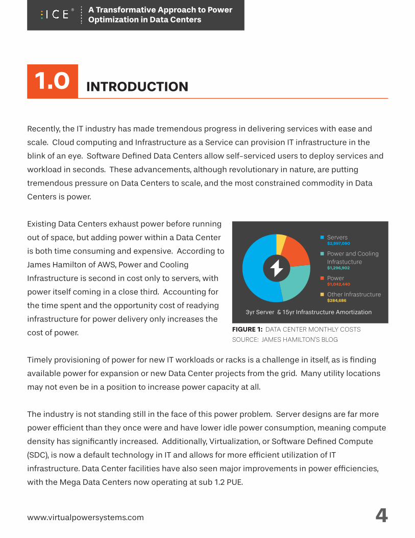
Existing Data Centers exhaust power before running
out of space, but adding power within a Data Center
is both time consuming and expensive. According to
James Hamilton of AWS, Power and Cooling
Infrastructure is second in cost only to servers, with
power itself coming in a close third. Accounting for
the time spent and the opportunity cost of readying
infrastructure for power delivery only increases the
cost of power.
Timely provisioning of power for new IT workloads or racks is a challenge in itself, as is finding
available power for expansion or new Data Center projects from the grid. Many utility locations
may not even be in a position to increase power capacity at all.
The industry is not standing still in the face of this power problem. Server designs are far more
power efficient than they once were and have lower idle power consumption, meaning compute
density has significantly increased. Additionally, Virtualization, or Software Defined Compute
(SDC), is now a default technology in IT and allows for more efficient utilization of IT
infrastructure. Data Center facilities have also seen major improvements in power efficiencies,
with the Mega Data Centers now operating at sub 1.2 PUE.
3yr Server & 15yr Infrastructure Amortization
Servers$2,997,090
Power and Cooling Infrastucture$1,296,902
Power$1,042,440
Other Infrastructure$284,686
FIGURE 1: DATA CENTER MONTHLY COSTS
SOURCE: JAMES HAMILTON’S BLOG
www.virtualpowersystems.com 4
1.0 INTRODUCTION
A Transformative Approach to Power Optimization in Data Centers
Such progress has helped drive efficiency in power utilization, but has not been able to improve
the power capacity utilization levels across the Data Center. The power infrastructure is still
over-provisioned and designed to serve peak loads. Current architectures entail rigid and static
allocation of power and power back-ups, locking and undermining power capacity and thus
lowering power utilization.
The problem of underutilization of capacity is not a new phenomenon in Data Centers and has
been successfully addressed in other non-power areas. Virtualization has increased the
productivity in server capacity and hence prevented server sprawl. The Software definition of
infrastructure is a key arena in the search to unlock lost capacity. Power infrastructure, which is
dominated by Hardware and Hardware vendors, has failed to make the same strides in Software
Defined Power® as it has in Hardware.
A fortuitous outcome of capacity repatriation with virtualization or software defined
infrastructure has been an increased level of automation and intelligence to infrastructure
management. This masks the increasing complexity of systems and architecture and enables
more efficient scaling and operations.
This paper defines a comprehensive approach to employing Software Defined Power to resolve
the power capacity problem across Data Centers. It begins with a description of current 2N
Redundant Data Centers that highlights where capacity is constrained. After this is an overview
of ICE (Intelligent Control of Energy) Hardware and Software solutions followed by the use cases
that demonstrate how locked capacity can be released using said solutions. We believe that the
methods described will optimize power capacity use by IT equipment when weighed empirically
to account for service levels and high availability requirements. The attendant improvement in
levels of automation and intelligent management of Data Centers will be a subject of separate
paper.
www.virtualpowersystems.com 5
A Transformative Approach to Power Optimization in Data Centers
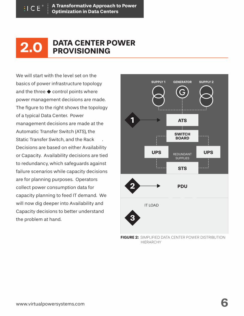
FIGURE 2: SIMPLIFIED DATA CENTER POWER DISTRIBUTION HIERARCHY
We will start with the level set on the
basics of power infrastructure topology
and the three control points where
power management decisions are made.
The figure to the right shows the topology
of a typical Data Center. Power
management decisions are made at the
Automatic Transfer Switch (ATS), the
Static Transfer Switch, and the Rack .
Decisions are based on either Availability
or Capacity. Availability decisions are tied
to redundancy, which safeguards against
failure scenarios while capacity decisions
are for planning purposes. Operators
collect power consumption data for
capacity planning to feed IT demand. We
will now dig deeper into Availability and
Capacity decisions to better understand
the problem at hand. 3
2
1
PDU
IT LOAD
STS
SWITCHBOARD
ATS
GENERATOR SUPPLY 2SUPPLY 1
UPSUPS REDUNDANTSUPPLIES
www.virtualpowersystems.com 6
2.0 DATA CENTER POWERPROVISIONING
G
A Transformative Approach to Power Optimization in Data Centers
2.1
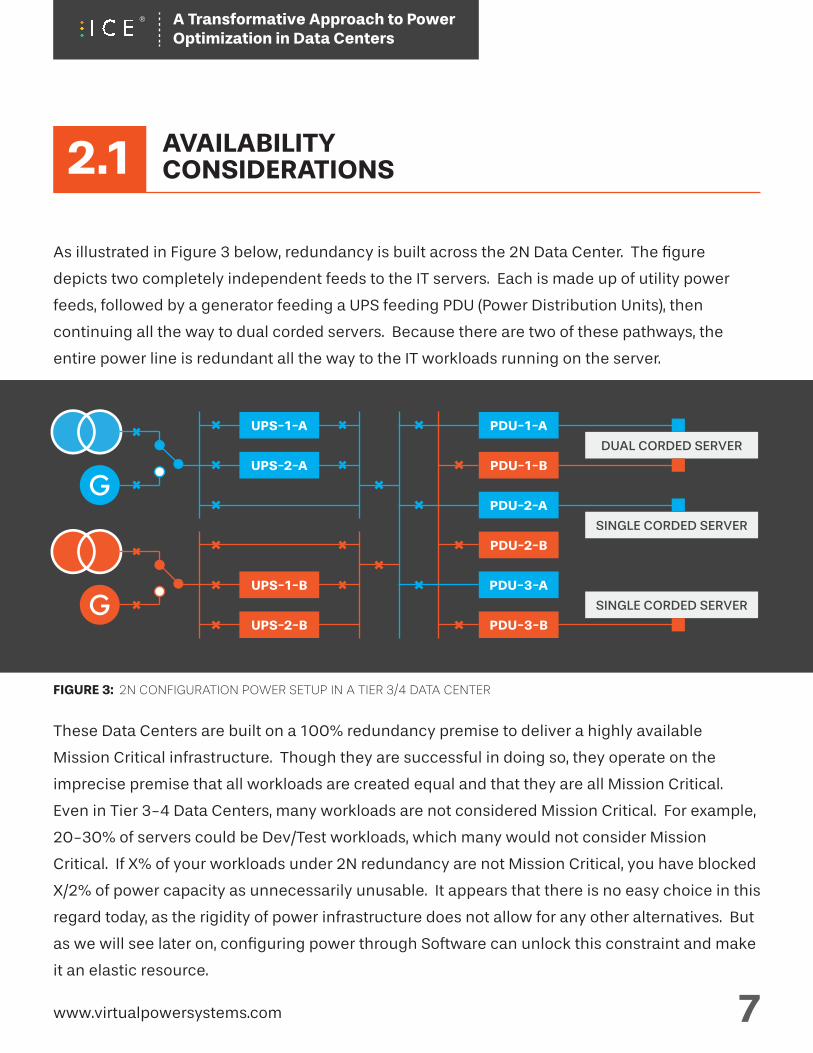
As illustrated in Figure 3 below, redundancy is built across the 2N Data Center. The figure
depicts two completely independent feeds to the IT servers. Each is made up of utility power
feeds, followed by a generator feeding a UPS feeding PDU (Power Distribution Units), then
continuing all the way to dual corded servers. Because there are two of these pathways, the
entire power line is redundant all the way to the IT workloads running on the server.
These Data Centers are built on a 100% redundancy premise to deliver a highly available
Mission Critical infrastructure. Though they are successful in doing so, they operate on the
imprecise premise that all workloads are created equal and that they are all Mission Critical.
Even in Tier 3-4 Data Centers, many workloads are not considered Mission Critical. For example,
20-30% of servers could be Dev/Test workloads, which many would not consider Mission
Critical. If X% of your workloads under 2N redundancy are not Mission Critical, you have blocked
X/2% of power capacity as unnecessarily unusable. It appears that there is no easy choice in this
regard today, as the rigidity of power infrastructure does not allow for any other alternatives. But
as we will see later on, configuring power through Software can unlock this constraint and make
it an elastic resource.
FIGURE 3: 2N CONFIGURATION POWER SETUP IN A TIER 3/4 DATA CENTER
PDU-1-A
DUAL CORDED SERVER
SINGLE CORDED SERVER
SINGLE CORDED SERVER
PDU-1-B
PDU-2-A
PDU-2-B
PDU-3-A
PDU-3-B
UPS-1-A
UPS-2-A
UPS-1-B
UPS-2-B
www.virtualpowersystems.com 7
AVAILABILITYCONSIDERATIONS
G
G
A Transformative Approach to Power Optimization in Data Centers
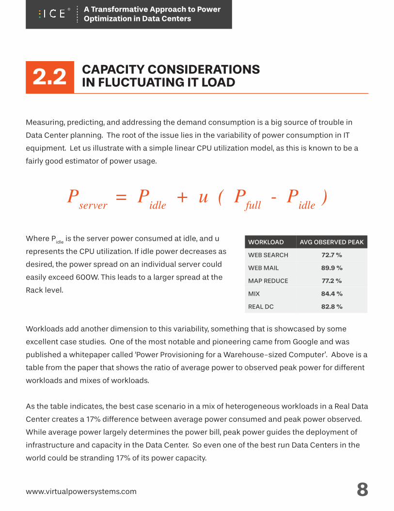
Measuring, predicting, and addressing the demand consumption is a big source of trouble in
Data Center planning. The root of the issue lies in the variability of power consumption in IT
equipment. Let us illustrate with a simple linear CPU utilization model, as this is known to be a
fairly good estimator of power usage.
Pserver = Pidle + u ( Pfull - Pidle )
Where Pidle
is the server power consumed at idle, and u
represents the CPU utilization. If idle power decreases as
desired, the power spread on an individual server could
easily exceed 600W. This leads to a larger spread at the
Rack level.
Workloads add another dimension to this variability, something that is showcased by some
excellent case studies. One of the most notable and pioneering came from Google and was
published a whitepaper called ‘Power Provisioning for a Warehouse-sized Computer’. Above is a
table from the paper that shows the ratio of average power to observed peak power for different
workloads and mixes of workloads.
As the table indicates, the best case scenario in a mix of heterogeneous workloads in a Real Data
Center creates a 17% difference between average power consumed and peak power observed.
While average power largely determines the power bill, peak power guides the deployment of
infrastructure and capacity in the Data Center. So even one of the best run Data Centers in the
world could be stranding 17% of its power capacity.
www.virtualpowersystems.com 8
AVG OBSERVED PEAK
72.7 %
89.9 %
77.2 %
84.4 %
82.8 %
WORKLOAD
WEB SEARCH
WEB MAIL
MAP REDUCE
MIX
REAL DC
2.2 CAPACITY CONSIDERATIONSIN FLUCTUATING IT LOAD
A Transformative Approach to Power Optimization in Data Centers
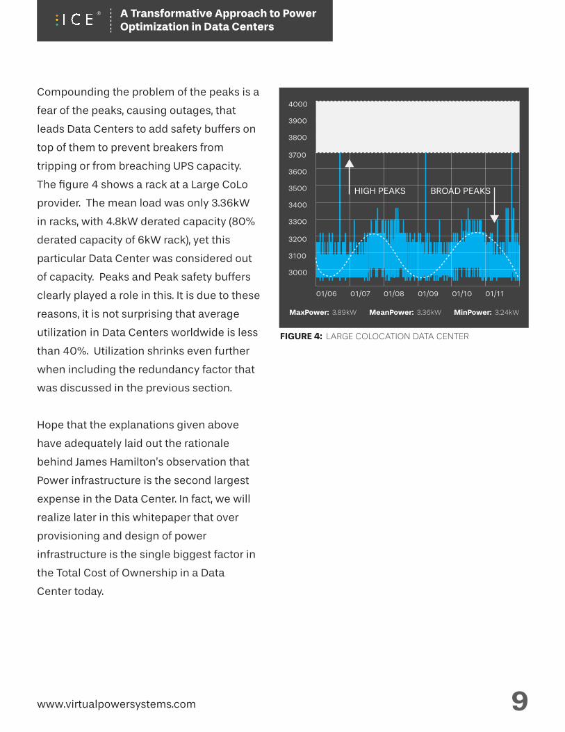
Compounding the problem of the peaks is a
fear of the peaks, causing outages, that
leads Data Centers to add safety buffers on
top of them to prevent breakers from
tripping or from breaching UPS capacity.
The figure 4 shows a rack at a Large CoLo
provider. The mean load was only 3.36kW
in racks, with 4.8kW derated capacity (80%
derated capacity of 6kW rack), yet this
particular Data Center was considered out
of capacity. Peaks and Peak safety buffers
clearly played a role in this. It is due to these
reasons, it is not surprising that average
utilization in Data Centers worldwide is less
than 40%. Utilization shrinks even further
when including the redundancy factor that
was discussed in the previous section.
Hope that the explanations given above
have adequately laid out the rationale
behind James Hamilton’s observation that
Power infrastructure is the second largest
expense in the Data Center. In fact, we will
realize later in this whitepaper that over
provisioning and design of power
infrastructure is the single biggest factor in
the Total Cost of Ownership in a Data
Center today.
www.virtualpowersystems.com 9
BROAD PEAKSHIGH PEAKS
01/06
3000
3100
3200
3300
3400
3500
3600
3700
3800
3900
4000
01/07 01/08 01/09 01/10 01/11
SAFETY BUFFER
FIGURE 4: LARGE COLOCATION DATA CENTER
MaxPower: 3.89kW MeanPower: 3.36kW MinPower: 3.24kW
A Transformative Approach to Power Optimization in Data Centers
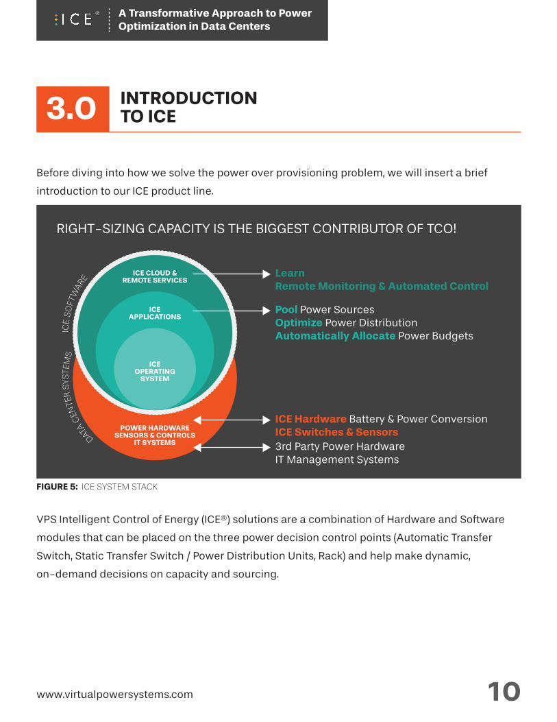
Before diving into how we solve the power over provisioning problem, we will insert a brief
introduction to our ICE product line.
VPS Intelligent Control of Energy (ICE®) solutions are a combination of Hardware and Software
modules that can be placed on the three power decision control points (Automatic Transfer
Switch, Static Transfer Switch / Power Distribution Units, Rack) and help make dynamic,
on-demand decisions on capacity and sourcing.
www.virtualpowersystems.com 10
3.0 INTRODUCTIONTO ICE
RIGHT-SIZING CAPACITY IS THE BIGGEST CONTRIBUTOR OF TCO!
POWER HARDWARE SENSORS & CONTROLS
IT SYSTEMS
ICE CLOUD &REMOTE SERVICES
ICEAPPLICATIONS
ICEOPERATING
SYSTEM
ICE
SO
FTW
ARE
DATA
CEN
TER
SYS
TEM
S
LearnRemote Monitoring & Automated Control
Pool Power SourcesOptimize Power DistributionAutomatically Allocate Power Budgets
ICE Hardware Battery & Power ConversionICE Switches & Sensors3rd Party Power HardwareIT Management Systems
FIGURE 5: ICE SYSTEM STACK
A Transformative Approach to Power Optimization in Data Centers
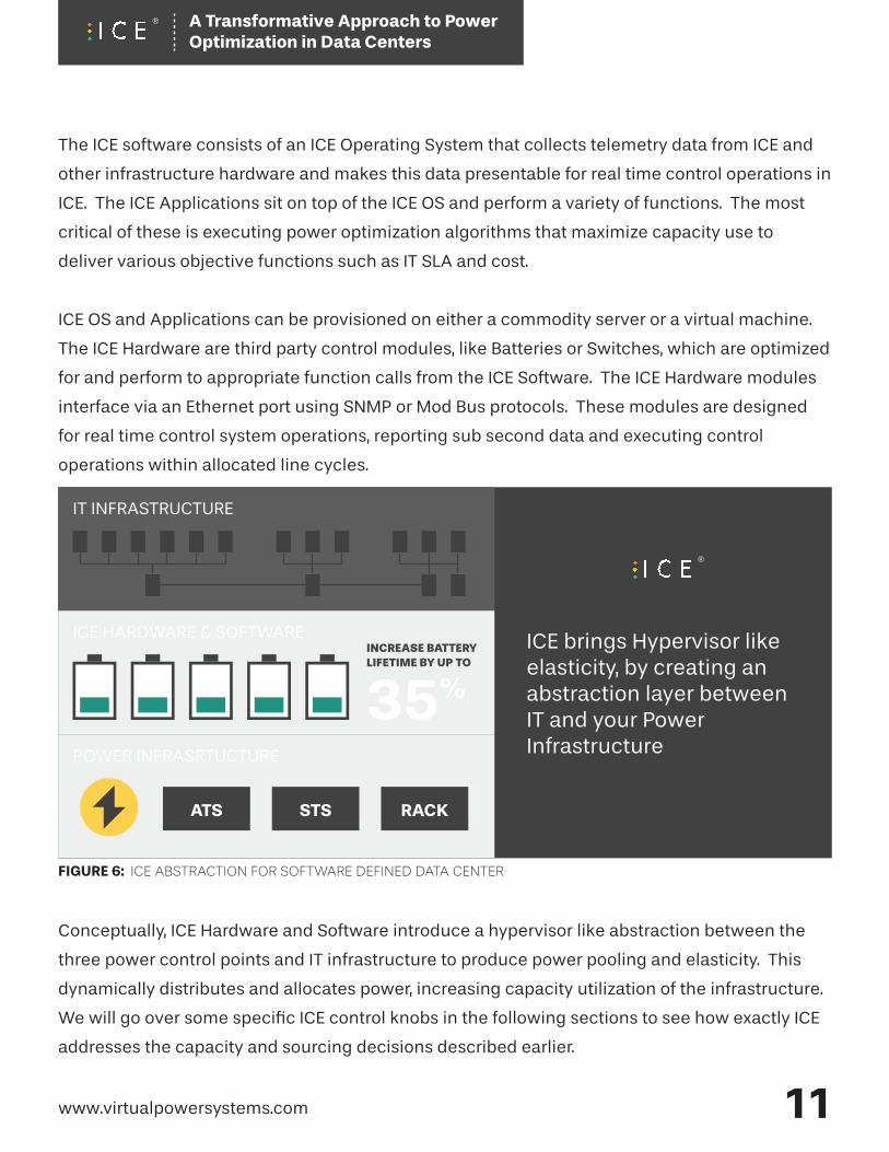
ICE brings Hypervisor like elasticity, by creating an abstraction layer between IT and your Power Infrastructure
ATS STS RACK
The ICE software consists of an ICE Operating System that collects telemetry data from ICE and
other infrastructure hardware and makes this data presentable for real time control operations in
ICE. The ICE Applications sit on top of the ICE OS and perform a variety of functions. The most
critical of these is executing power optimization algorithms that maximize capacity use to
deliver various objective functions such as IT SLA and cost.
ICE OS and Applications can be provisioned on either a commodity server or a virtual machine.
The ICE Hardware are third party control modules, like Batteries or Switches, which are optimized
for and perform to appropriate function calls from the ICE Software. The ICE Hardware modules
interface via an Ethernet port using SNMP or Mod Bus protocols. These modules are designed
for real time control system operations, reporting sub second data and executing control
operations within allocated line cycles.
Conceptually, ICE Hardware and Software introduce a hypervisor like abstraction between the
three power control points and IT infrastructure to produce power pooling and elasticity. This
dynamically distributes and allocates power, increasing capacity utilization of the infrastructure.
We will go over some specific ICE control knobs in the following sections to see how exactly ICE
addresses the capacity and sourcing decisions described earlier.
www.virtualpowersystems.com 11
IT INFRASTRUCTURE
ICE HARDWARE & SOFTWARE
POWER INFRASRTUCTURE
35%
INCREASE BATTERY LIFETIME BY UP TO
FIGURE 6: ICE ABSTRACTION FOR SOFTWARE DEFINED DATA CENTER
A Transformative Approach to Power Optimization in Data Centers
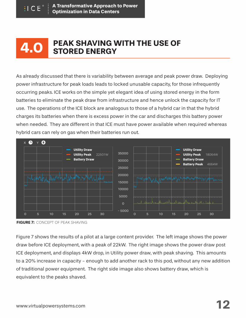
As already discussed that there is variability between average and peak power draw. Deploying
power infrastructure for peak loads leads to locked unusable capacity, for those infrequently
occurring peaks. ICE works on the simple yet elegant idea of using stored energy in the form
batteries to eliminate the peak draw from infrastructure and hence unlock the capacity for IT
use. The operations of the ICE block are analogous to those of a hybrid car in that the hybrid
charges its batteries when there is excess power in the car and discharges this battery power
when needed. They are different in that ICE must have power available when required whereas
hybrid cars can rely on gas when their batteries run out.
Figure 7 shows the results of a pilot at a large content provider. The left image shows the power
draw before ICE deployment, with a peak of 22kW. The right image shows the power draw post
ICE deployment, and displays 4kW drop, in Utility power draw, with peak shaving. This amounts
to a 20% increase in capacity - enough to add another rack to this pod, without any new addition
of traditional power equipment. The right side image also shows battery draw, which is
equivalent to the peaks shaved.
www.virtualpowersystems.com 12
4.0 PEAK SHAVING WITH THE USE OFSTORED ENERGY
0
5000
- 5000
10000
15000
20000
25000
30000
35000
X
0 5 10 15 20 25 30 0 5 10 15 20 25 30
FIGURE 7: CONCEPT OF PEAK SHAVING
Utility Draw
Utility Peak 18064W
Battery Draw
Battery Peak 4664W
Utility Draw
Utility Peak 22501W
Battery Draw
Y
A Transformative Approach to Power Optimization in Data Centers
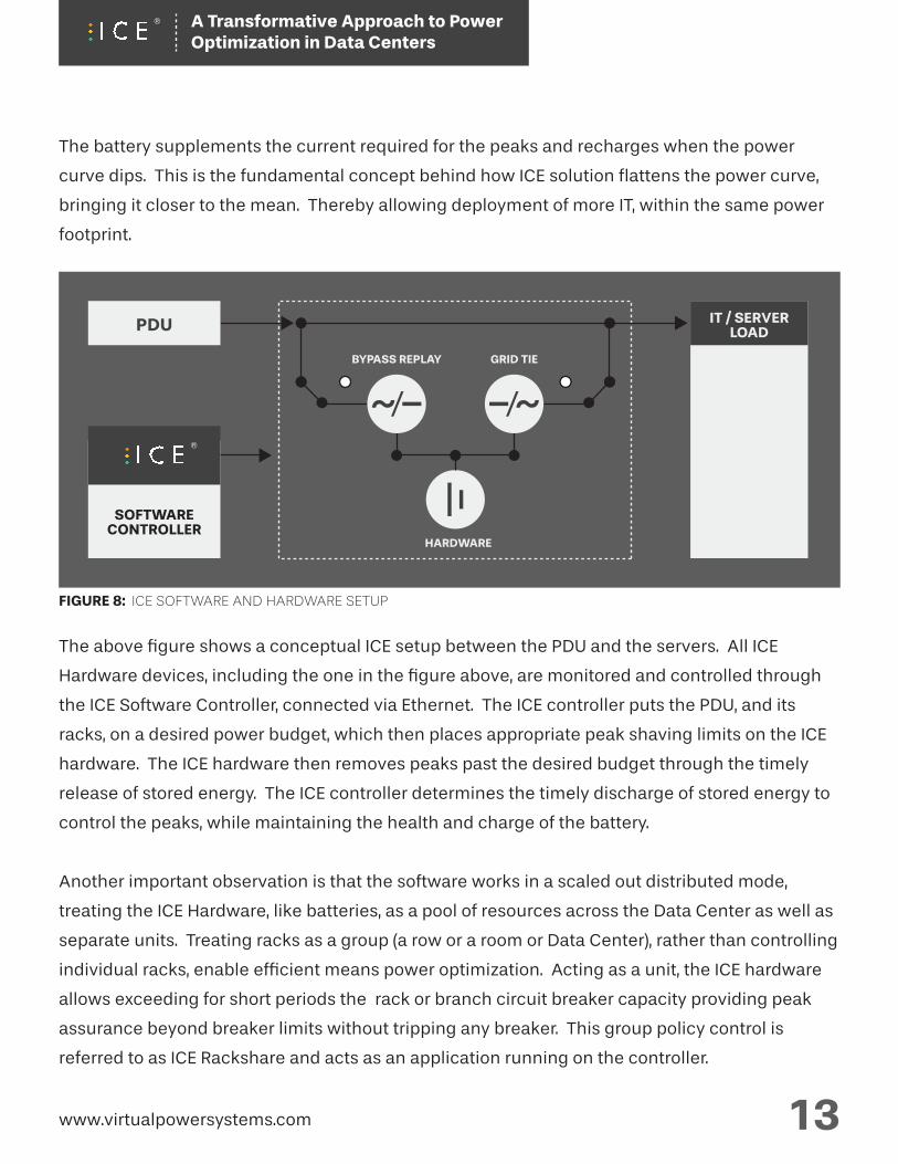
The battery supplements the current required for the peaks and recharges when the power
curve dips. This is the fundamental concept behind how ICE solution flattens the power curve,
bringing it closer to the mean. Thereby allowing deployment of more IT, within the same power
footprint.
The above figure shows a conceptual ICE setup between the PDU and the servers. All ICE
Hardware devices, including the one in the figure above, are monitored and controlled through
the ICE Software Controller, connected via Ethernet. The ICE controller puts the PDU, and its
racks, on a desired power budget, which then places appropriate peak shaving limits on the ICE
hardware. The ICE hardware then removes peaks past the desired budget through the timely
release of stored energy. The ICE controller determines the timely discharge of stored energy to
control the peaks, while maintaining the health and charge of the battery.
Another important observation is that the software works in a scaled out distributed mode,
treating the ICE Hardware, like batteries, as a pool of resources across the Data Center as well as
separate units. Treating racks as a group (a row or a room or Data Center), rather than controlling
individual racks, enable efficient means power optimization. Acting as a unit, the ICE hardware
allows exceeding for short periods the rack or branch circuit breaker capacity providing peak
assurance beyond breaker limits without tripping any breaker. This group policy control is
referred to as ICE Rackshare and acts as an application running on the controller.
www.virtualpowersystems.com 13
FIGURE 8: ICE SOFTWARE AND HARDWARE SETUP
IT / SERVERLOAD
SOFTWARECONTROLLER
HARDWARE
GRID TIEBYPASS REPLAY
PDU
A Transformative Approach to Power Optimization in Data Centers
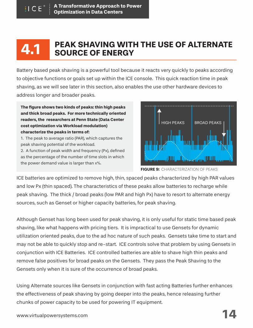
The figure shows two kinds of peaks: thin high peaks
and thick broad peaks. For more technically oriented
readers, the researchers at Penn State (Data Center
cost optimization via Workload modulation)
characterize the peaks in terms of:
1. The peak to average ratio (PAR), which captures the
peak shaving potential of the workload.
2. A function of peak width and frequency (Px), defined
as the percentage of the number of time slots in which
the power demand value is larger than x%.
4.1Battery based peak shaving is a powerful tool because it reacts very quickly to peaks according
to objective functions or goals set up within the ICE console. This quick reaction time in peak
shaving, as we will see later in this section, also enables the use other hardware devices to
address longer and broader peaks.
ICE batteries are optimized to remove high, thin, spaced peaks characterized by high PAR values
and low Px (thin spaced). The characteristics of these peaks allow batteries to recharge while
peak shaving. The thick / broad peaks (low PAR and high Px) have to resort to alternate energy
sources, such as Genset or higher capacity batteries, for peak shaving.
Although Genset has long been used for peak shaving, it is only useful for static time based peak
shaving, like what happens with pricing tiers. It is impractical to use Gensets for dynamic
utilization oriented peaks, due to the ad hoc nature of such peaks. Gensets take time to start and
may not be able to quickly stop and re-start. ICE controls solve that problem by using Gensets in
conjunction with ICE Batteries. ICE controlled batteries are able to shave high thin peaks and
remove false positives for broad peaks on the Gensets. They pass the Peak Shaving to the
Gensets only when it is sure of the occurrence of broad peaks.
Using Alternate sources like Gensets in conjunction with fast acting Batteries further enhances
the effectiveness of peak shaving by going deeper into the peaks, hence releasing further
chunks of power capacity to be used for powering IT equipment.
FIGURE 9: CHARACTERIZATION OF PEAKS
www.virtualpowersystems.com 14
BROAD PEAKSHIGH PEAKS
PEAK SHAVING WITH THE USE OF ALTERNATE SOURCE OF ENERGY
A Transformative Approach to Power Optimization in Data Centers
400kW
400kW
BREAKER CAPACITY
BREAKER CAPACITY
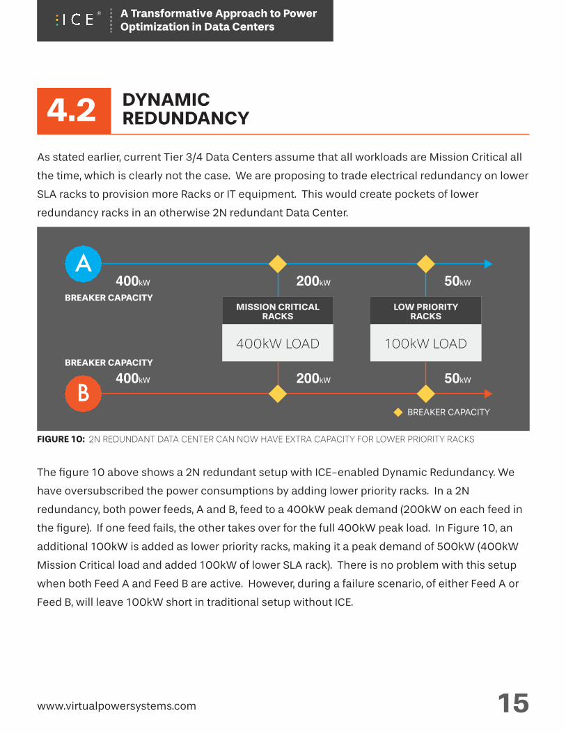
4.2As stated earlier, current Tier 3/4 Data Centers assume that all workloads are Mission Critical all
the time, which is clearly not the case. We are proposing to trade electrical redundancy on lower
SLA racks to provision more Racks or IT equipment. This would create pockets of lower
redundancy racks in an otherwise 2N redundant Data Center.
The figure 10 above shows a 2N redundant setup with ICE-enabled Dynamic Redundancy. We
have oversubscribed the power consumptions by adding lower priority racks. In a 2N
redundancy, both power feeds, A and B, feed to a 400kW peak demand (200kW on each feed in
the figure). If one feed fails, the other takes over for the full 400kW peak load. In Figure 10, an
additional 100kW is added as lower priority racks, making it a peak demand of 500kW (400kW
Mission Critical load and added 100kW of lower SLA rack). There is no problem with this setup
when both Feed A and Feed B are active. However, during a failure scenario, of either Feed A or
Feed B, will leave 100kW short in traditional setup without ICE.
DYNAMICREDUNDANCY
www.virtualpowersystems.com 15
A
B200kW
200kW
BREAKER CAPACITY
FIGURE 10: 2N REDUNDANT DATA CENTER CAN NOW HAVE EXTRA CAPACITY FOR LOWER PRIORITY RACKS
100kW LOAD
LOW PRIORITYRACKS
400kW LOAD
MISSION CRITICALRACKS
50kW
50kW
A Transformative Approach to Power Optimization in Data Centers
A
400kW400kW
400kW
BREAKER CAPACITY
BREAKER CAPACITY
0kW
BREAKER CAPACITY
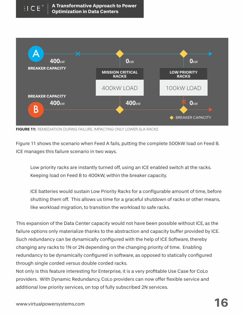
FIGURE 11: REMEDIATION DURING FAILURE, IMPACTING ONLY LOWER SLA RACKS
100kW LOAD
LOW PRIORITYRACKS
400kW LOAD
MISSION CRITICALRACKS
0kW
0kW
Figure 11 shows the scenario when Feed A fails, putting the complete 500kW load on Feed B.
ICE manages this failure scenario in two ways.
Low priority racks are instantly turned off, using an ICE enabled switch at the racks.
Keeping load on Feed B to 400kW, within the breaker capacity.
ICE batteries would sustain Low Priority Racks for a configurable amount of time, before
shutting them off. This allows us time for a graceful shutdown of racks or other means,
like workload migration, to transition the workload to safe racks.
This expansion of the Data Center capacity would not have been possible without ICE, as the
failure options only materialize thanks to the abstraction and capacity buffer provided by ICE.
Such redundancy can be dynamically configured with the help of ICE Software, thereby
changing any racks to 1N or 2N depending on the changing priority of time. Enabling
redundancy to be dynamically configured in software, as opposed to statically configured
through single corded versus double corded racks.
Not only is this feature interesting for Enterprise, it is a very profitable Use Case for CoLo
providers. With Dynamic Redundancy, CoLo providers can now offer flexible service and
additional low priority services, on top of fully subscribed 2N services.
www.virtualpowersystems.com 16
B
A Transformative Approach to Power Optimization in Data Centers
UP TO 50% REDUCTIONIN COST / WATT
$76k SAVED PER RACK OVER DC LIFETIMEDerrived from APC Whitepaper #6Determining Total Cost of Ownership
5.0
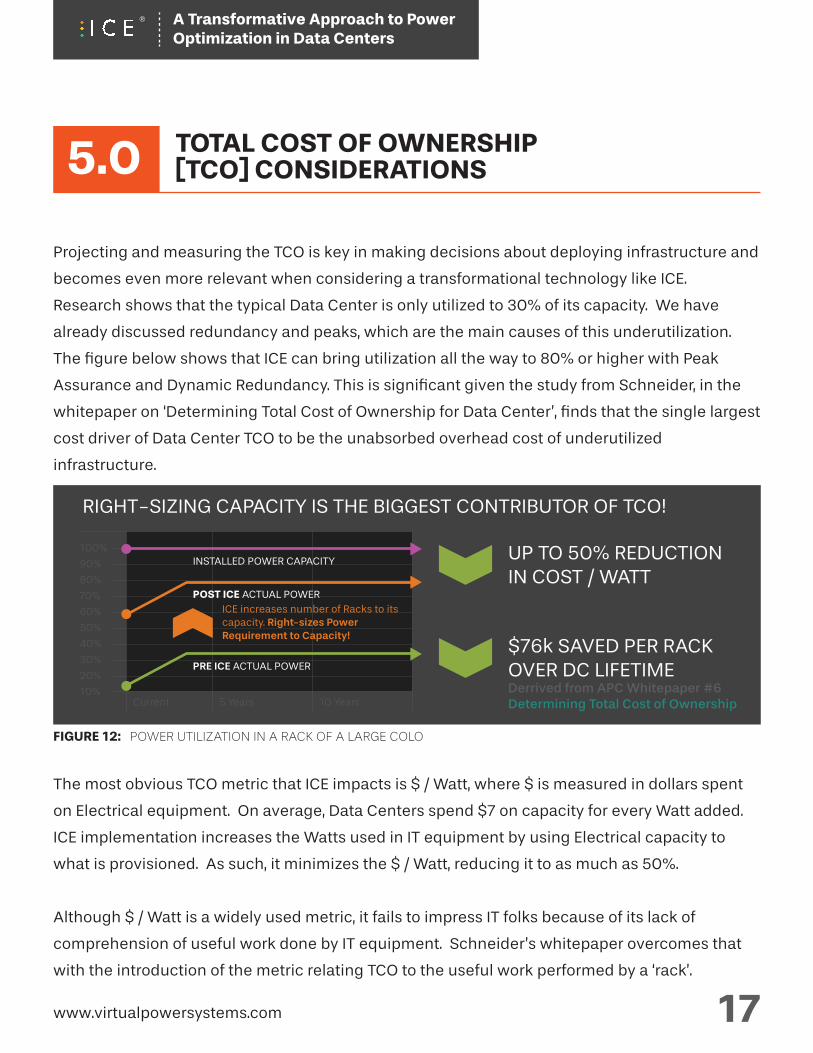
Projecting and measuring the TCO is key in making decisions about deploying infrastructure and
becomes even more relevant when considering a transformational technology like ICE.
Research shows that the typical Data Center is only utilized to 30% of its capacity. We have
already discussed redundancy and peaks, which are the main causes of this underutilization.
The figure below shows that ICE can bring utilization all the way to 80% or higher with Peak
Assurance and Dynamic Redundancy. This is significant given the study from Schneider, in the
whitepaper on ‘Determining Total Cost of Ownership for Data Center’, finds that the single largest
cost driver of Data Center TCO to be the unabsorbed overhead cost of underutilized
infrastructure.
The most obvious TCO metric that ICE impacts is $ / Watt, where $ is measured in dollars spent
on Electrical equipment. On average, Data Centers spend $7 on capacity for every Watt added.
ICE implementation increases the Watts used in IT equipment by using Electrical capacity to
what is provisioned. As such, it minimizes the $ / Watt, reducing it to as much as 50%.
Although $ / Watt is a widely used metric, it fails to impress IT folks because of its lack of
comprehension of useful work done by IT equipment. Schneider’s whitepaper overcomes that
with the introduction of the metric relating TCO to the useful work performed by a ‘rack’.
FIGURE 12: POWER UTILIZATION IN A RACK OF A LARGE COLO
5 YearsCurrent 10 Years
TOTAL COST OF OWNERSHIP[TCO] CONSIDERATIONS
RIGHT-SIZING CAPACITY IS THE BIGGEST CONTRIBUTOR OF TCO!
www.virtualpowersystems.com 17
100%
90%
80%
70%
60%
50%
40%
30%
10%
20%
ICE increases number of Racks to its capacity. Right-sizes Power Requirement to Capacity!
INSTALLED POWER CAPACITY
PRE ICE ACTUAL POWER
POST ICE ACTUAL POWER
A Transformative Approach to Power Optimization in Data Centers
Since the only unit of work in a Data Center is IT equipment hosted in a rack, expressing facility
infrastructure in terms of ‘Racks’ is gaining wide acceptance. The Total Cost of Ownership of a
Rack in a Data Center is approximately $120k over the Data Center depreciation lifecycle
(usually 10 years). The ‘Right-sized use of the systems to the actual requirement’ was found to
be the biggest TCO factor, saving $76,400 per rack over 10 years. Assuming that there are 15
servers in each rack, this amounts to $2000 per server. Since the average server costs $4000,
this corresponds to 50% of the server’s cost, a substantial savings delivered in the area that
Schneider rightly identifies as the biggest TCO factor.
www.virtualpowersystems.com 18
A Transformative Approach to Power Optimization in Data Centers
6.0We hope that this paper has thoroughly described how VPS’ Intelligent Control of Energy (ICE®)
solutions provide a flexible Software defined solution to the problem of stranded power capacity
in Data Centers. Below is a brief summary of its main points.
Power Infrastructure today is over provisioned, yet most Data Centers are running out of power.
This is due to the fact that power capacity is locked and unusable due to Peaks in power
consumption and Redundancy for High Availability. A significant part of such power capacity
can be unlocked through Software defined Power.
ICE unlocks unusable power capacity and increases power utilization levels. This allows existing
Data Centers to stack more workload in their existing power footprint. New Data Centers can
build smaller power footprints with existing workload plans.
ICE unlocks such capacity in two ways.
1. By the use of Stored Energy (Battery / Genset).
2. Controlling Redundancy only as needed. Software plays a critical role in managing both
these approaches.
The optimal use of power capacity, or right-sizing the provisioned capacity, delivers significant
reduction in Total Cost of Ownership.
In essence, ICE uses a systematic approach to overcome the limitations imposed by uncertainty
about the current and the future operations, likely failure scenarios, and lack of precise controls.
It delivers the most cost optimized solution for the Data Center through a variety of control
knobs.
CONCLUSION
www.virtualpowersystems.com 19
A Transformative Approach to Power Optimization in Data Centers
Power provisioning for a warehouse-sized computer
Xiaobo Fan, Wolf-Dietrich Weber, and Luiz Andre Barroso - ISCA: 2007
Cost of Power in Large-Scale Data Centers
James Hamilton: 2008
Data Center Cost Optimization Via Workload Modulation Under Real-World Electricity
Pricing
Cheng Wang, Bhuvan Urgaonkar, Qian Wang, George Kesidis, and Anand Sivasubramaniam -
Cornell University Library: 2013
Determining Total Cost of Ownership for Data Center and Network Room Infrastructure
http://www.schneider-electric.com/au/en/download/document/APC_CMRP-5T9PQG_EN
REFERENCES
www.virtualpowersystems.com 20
A Transformative Approach to Power Optimization in Data Centers