Embed Size (px)
Citation preview
ON2 TECHNOLOGIES, INC.
VP6 BITSTREAM &
DECODER
SPECIFICATION
August 17, 2006
Document version: 1.02
© On2 Technologies Inc 2006
On2 Technologies, Inc. 21 Corporate Drive, Suite 103 Clifton Park, NY 12065 www.on2.com
VP6 Bitstream & Decoder Specif ication COMPANY CONFIDENTIAL
August 17, 2006 © On2 Technologies Inc 2006 2
Contents
1 Introduction......................................................................................................................... 7
2 VP6 Algorithm Fundamentals ............................................................................................ 7
3 Nomenclature...................................................................................................................... 8
4 Frame Types ....................................................................................................................... 9
5 Coding Profiles ................................................................................................................... 9
6 Data Partitioning ............................................................................................................... 10
7 Entropy Coding................................................................................................................. 10
7.1 Contexts ..................................................................................................................... 11
7.2 Huffman Decoder....................................................................................................... 11
7.3 BoolCoder.................................................................................................................. 15
8 Bitstream Map................................................................................................................... 16
9 Frame Header.................................................................................................................... 23
10 Mode Decoding .......................................................................................................... 27
11 Motion Vectors........................................................................................................... 37
11.1 Decoding a Motion Vector......................................................................................... 38
11.2 Motion Vector Probability Updates ........................................................................... 42
11.3 Prediction Loop Filtering........................................................................................... 44
11.4 Filtering For Fractional Pixel Motion Compensation ................................................ 47
11.5 Support For Unrestricted Motion Vectors.................................................................. 53
12 Scan Orders ................................................................................................................ 53
12.1 Default Scan Order .................................................................................................... 54
12.2 Custom Scan Order .................................................................................................... 55
13 DCT Coefficient Token Set and Decoding ................................................................ 56
13.1 DCT Token Huffman Tree......................................................................................... 60
13.2 DC Decoding ............................................................................................................. 61
13.3 AC Decoding ............................................................................................................. 67
VP6 Bitstream & Decoder Specif ication COMPANY CONFIDENTIAL
August 17, 2006 © On2 Technologies Inc 2006 3
13.4 Decoding Huffman EOB and DC 0 Runs .................................................................. 80
14 DC Prediction............................................................................................................. 81
15 Inverse Quantization................................................................................................... 82
16 Inverse DCT Transform ............................................................................................. 83
17 Frame Reconstruction................................................................................................. 85
17.1 Intra Coded Blocks .................................................................................................... 86
17.2 Zero Vectors .............................................................................................................. 86
17.3 Full Pixel Aligned Vectors......................................................................................... 86
17.4 Fractional Pixel Aligned Vectors............................................................................... 87
18 Document Revision History ....................................................................................... 88
VP6 Bitstream & Decoder Specif ication COMPANY CONFIDENTIAL
August 17, 2006 © On2 Technologies Inc 2006 4
List of Tables
Table 1 Frame Header ............................................................................................................. 23
Table 2 IntraHeader Definition ............................................................................................... 24
Table 3 InterHeader Definition ............................................................................................... 26
Table 4 Coding Modes ............................................................................................................ 27
Table 5 Mode Availability Values for Dimension 1 of Mode Probability Vector .................. 29
Table 6 ProbabilitySituation Table.......................................................................................... 30
Table 7 Bitstream Section : Mode Probability Updates .......................................................... 30
Table 8 Mode Probability Updates Section............................................................................. 30
Table 9 ModeProbUpdateVector............................................................................................. 33
Table 10 Block Coding Mode Signaling ................................................................................. 37
Table 11 Decoding a Motion Vector Component ................................................................... 39
Table 12 Probability data structures used in decoding motion vectors ................................... 39
Table 13 Motion Vector Tree Probability Coding .................................................................. 42
Table 14 Short MV Tree Node updates................................................................................... 43
Table 15 Long motion vector bit probability updates ............................................................. 44
Table 16 Custom scan order bands.......................................................................................... 55
Table 17 Scan Order Update ................................................................................................... 56
Table 18 Token Set and Extrabits ........................................................................................... 57
Table 19 Special DCT Tokens ................................................................................................ 58
Table 20 DC & AC Coding Tree Node Probability Values .................................................... 60
Table 21 DC Node Contexts Dimension 1 Index.................................................................... 61
Table 22 DC Coding Tree Plane Probability Updates............................................................. 61
Table 23 DC Coding Tree Node Updates................................................................................ 62
Table 24 DC Coding Tree Update Structure ........................................................................... 62
Table 25 DC Node Plane......................................................................................................... 63
Table 26 DC Node Contexts ................................................................................................... 63
Table 27 DCNodeEqs Dimension 3 ........................................................................................ 64
Table 28 AC Prob Plane Index................................................................................................ 67
Table 29 AC Prob Prec Index................................................................................................. 67
Table 30 AC Prob Band Index ................................................................................................ 68
Table 31 Plane AC Coding Tree Probability Updates............................................................. 68
Table 32 Plane AC Coding Tree Plane Probability Updates................................................... 68
Table 33 AC Coding Tree Band Probability Updates ............................................................. 69
Table 34 AC Coding Tree Node Probability Updates............................................................. 69
Table 35 AC Coding Tree Update........................................................................................... 70
Table 36 AC Huffman Prob Band Index................................................................................. 73
VP6 Bitstream & Decoder Specif ication COMPANY CONFIDENTIAL
August 17, 2006 © On2 Technologies Inc 2006 5
Table 37 ZRL Band Index....................................................................................................... 76
Table 38 ZRL Node Index....................................................................................................... 76
Table 39 Updates to ZRL Probabibilities Band ...................................................................... 77
Table 40 Updates to ZeroRunNodes ....................................................................................... 77
Table 41 Updates to ZeroRunNode Probability ...................................................................... 78
VP6 Bitstream & Decoder Specif ication COMPANY CONFIDENTIAL
August 17, 2006 © On2 Technologies Inc 2006 6
List of Figures
Figure 1 VP6 Bitstream........................................................................................................... 16
Figure 2 Single Stream -- Macroblock Info ............................................................................ 17
Figure 3 Bool Coded – Multi-Stream Macroblock Info .......................................................... 18
Figure 4 Huffman Coded -- Multi-Stream Macroblock Info................................................... 19
Figure 5 Coefficient Probability Updates................................................................................ 20
Figure 6 Encode Macroblock Prediction Information............................................................. 21
Figure 7 Macroblock's Coefficients ........................................................................................ 22
Figure 8 Block Coefficients .................................................................................................... 22
Figure 9 Mode Probability Update Magnitude Tree ............................................................... 33
Figure 10 Mode decoding decision tree .................................................................................. 35
Figure 11 Short MV Component Magnitude Decoding Tree.................................................. 40
Figure 12 Prediction Loop Filtering of 8x8 Block Boundaries ............................................... 45
Figure 13 Extension of the reconstruction buffer to create UMV borders .............................. 53
Figure 14 Default zig-zag scan order ..................................................................................... 54
Figure 15 Binary Coding Tree for DC & AC Tokens ............................................................. 59
Figure 16 AC Zero run length binary tree ............................................................................... 75
Figure 17 Huffman EOB Run Lengths.................................................................................... 81
VP6 Bitstream & Decoder Specif ication COMPANY CONFIDENTIAL
August 17, 2006 © On2 Technologies Inc 2006 7
1 INTRODUCTION
This document specifies the format of the VP6 compressed video bitstream created by On2
Technologies Inc. It is accompanied by a set of C programming language source code files
that together form a fully operational reference implementation of a VP6 decoder.
VP6 is a leading edge video compression algorithm that uses motion compensated prediction,
Discrete Cosine Transform (DCT) coding of the prediction error signal and context
dependent entropy coding techniques based on Huffman and arithmetic principles. Section 2
gives a list of the main features.
Throughout the document various notational devices are used to convey meaning when
describing the format and operation of the bitstream and decoder. These are outlined in
Section 3.
Sections 4 to 6 detail various structural aspects of the bitstream and data formats. This is
followed by a description of the two entropy algorithms used in the decoder in Section 7.
The description of the bitstream begins in Section 8 with a set of diagrams that show the top-
level building blocks and their relative order. The remaining sections, 9 to17, give the
detailed low-level syntactic and semantic descriptions of all aspects of the bitstream and the
interpretation of the bitstream.
A final section provides the document revision history.
All ambiguities between the algorithm described in this document and the accompanying
reference software should be resolved in favor of the reference software.
2 VP6 ALGORITHM FUNDAMENTALS
VP6 is a leading edge video compression algorithm having the following features:
� YUV 4:2:0 image format
� Macro-block (MB) based coding (MB is 16x16 luma plus two 8x8 chroma)
� ¼ pixel accuracy motion compensated prediction
� 8x8 DCT transform
� 64-level linear quantizer
� Prediction loop filter
� Frame variable quantization level
� Scaling on output after decode
� Two entropy coding strategies: Huffman & Binary Arithmetic (BoolCoder)
� Extensive context-based entropy coding strategy
VP6 Bitstream & Decoder Specif ication COMPANY CONFIDENTIAL
August 17, 2006 © On2 Technologies Inc 2006 8
3 NOMENCLATURE
In the tables in this document that outline the bitstream format the following method has been
Similar to the definitions used in the C programming language, the following operators are
used throughout this document:
+ Addition
- Subtraction (as a binary operator) or negation (as a unary operator).
× Multiplication
÷ Division
++ Increment: e.g. x++ represents x = x + 1
-- Decrement: e.g. x++ represents x = x - 1
Sign( )
Abs( )
|| Logical OR
&& Logical AND
! Logical NOT
> Greater than
>= Greater than or equal to
< Less than
<= Less than or equal to
== Equal to
!= Not equal to
& Bitwise AND
| Bitwise OR
>> Shift right with sign extension
<< Shift left with zero fill
= Assignment operator

VP6 Bitstream & Decoder Specif ication COMPANY CONFIDENTIAL
August 17, 2006 © On2 Technologies Inc 2006 9
Tables that outline the format of the bitstream refer to the following operators to indicate how
bits are stored in the bitstream (in the ‘Type’ column):
� R(x) indicates a sequence of x-bits written directly to the bitstream as a sequence of raw
bits,
� B(x) indicates a single bit encoded using the BoolCoder with node probability x,
� b(x) indicates a sequence of x-bits encoded using the BoolCoder with a fixed node
probability of 128 for each bit,
� T indicates a multi-bit syntax element that is encoded using the BoolCoder with reference
to a specified decision tree and corresponding set of node probabilities.
These operators are also referred to in the pseudo-code segments. The BoolCoder will be
described in the Section 7.3.
4 FRAME TYPES
VP6 defines only two frame types, intra-coded and inter-coded.
Intra, or I-frames, may be reconstructed from their compressed representation with no
reference to other frames in the sequence. I-frames provide entry points into the bitstream that
do not require preceding frames to be decoded providing a method of fast random access.
Inter, prediction or P-frames, are encoded differentially with respect to a previously encoded
reference frame in the sequence. This reference frame may either be the reconstruction of the
immediately previous frame in the sequence or a stored previous frame known as the Golden
Frame, described below.
The alternative prediction, or Golden Frame, is a frame buffer that by default holds the last
decoded I-frame but it may be updated at any time. A flag in the frame header indicates to the
decoder whether or not to update the Golden Frame buffer.
To update the Golden frame the current frame is first decoded and then copied in its entirety
(including any UMV border (see Section 11.5)) into the Golden frame buffer.
It should be noted that VP6 makes no use of backward or bi-directional prediction.
Specifically, there is no equivalent to the MPEG B-frame.
5 CODING PROFILES
Certain techniques used within the codec require significant computational resources that
may not be available on low-end or even higher end processors for the very largest image
formats. In an attempt to reflect this two profiles are defined, Simple and Advanced. Each
frame header contains a flag, VpProfile, which indicates the profile that was used to code it.
In both profiles the BoolCoder is used for encoding block and macro-block coding mode
decisions and motion vectors in the first data partition.
When encoding in Simple Profile the DCT tokens are encoded in a second data partition,
indicated in the bitstream by setting the MultiStream flag in the frame header. Furthermore,
VP6 Bitstream & Decoder Specif ication COMPANY CONFIDENTIAL
August 17, 2006 © On2 Technologies Inc 2006 10
to reduce computational complexity both the prediction loop-filter and bi-cubic prediction
filter are disabled.
When using Advanced Profile the second partition is optional depending on the MultiStream
flag in the frame header. Where it is absent, all encoded data appears a single partition
encoded using the BoolCoder. The second partition may be encoded using either the Huffman
or BoolCoder entropy schemes. In addition, the use of the prediction loop-filter is optionally
enabled, depending on a flag in the frame header, and the prediction filter type may be
dynamically switched between bi-linear and bi-cubic variants.
In either profile where the second partition is present the UseHuffman flag in the frame
header signifies whether the data is encoded using the Huffman or BoolCoder entropy
schemes.
6 DATA PARTITIONING
A compressed frame is represented in the bitstream as a short header together with either one
or two further partitions output as a contiguous stream of bytes. The second partition is
optional, an encoder signals its presence or otherwise by setting the MultiStream flag as
appropriate in the frame header (see Section 9).
The two partitions may use different entropy coding methods as follows:
� Partition 1: Always encoded using the BoolCoder,
� Partition 2: Encoded with either the BoolCoder or the Huffman coder.
If the second partition is used the value Buff2Offset in the frame header gives the offset from
the start of the compressed frame buffer to the first byte of the partition.
The decision as to whether one or two data partitions are used is an encoder decision and is
indicated by the flag in the frame header.
7 ENTROPY CODING
There are two alternative entropy coding strategies, the Huffman Coder and the BoolCoder.
The Huffman coder is a very computationally efficient method that is well suited to speed
optimization and has reasonable compression performance. It is typically used in very high
data-rate scenarios on low to mid-range processors because it can handle the large volume of
tokens more efficiently than the BoolCoder.
The BoolCoder is a simplified binary arithmetic coder allowing tokens to be encoded with
fractions of a bit. It is much more efficient in terms of compression performance than the
Huffman coder, but this comes with a significantly increased computational complexity.
Both the Huffman coder and BoolCoder use binary decision trees to represent multi-bit
syntax elements. In each case the tree is traversed as a sequence of branch decisions is read
from the bitstream until a leaf node is reached. Each leaf node has an associated syntax
element.
VP6 Bitstream & Decoder Specif ication COMPANY CONFIDENTIAL
August 17, 2006 © On2 Technologies Inc 2006 11
The difference between the two schemes lies in the way that a branch decision is encoded at
each node in the tree. The Huffman coder encodes a whole bit to indicate which way to
branch, 0 for left, 1 for right. However, the BoolCoder associates a probability value with
each node (referred to as the Node Probability), being the probability of taking the left (or
zero) branch. By doing so the BoolCoder can achieve sub-bit decision costs.
Whereas the Huffman coder is completely specified by the binary decision tree, the
BoolCoder additionally requires the definition of a set of Node Probabilities. Node
probabilities are specified as an array of values, specified in order as the tree is traversed in
depth-first order.
Node probabilities are represented on a linear 8-bit scale: 0 represents probability 0, 255
represents probability 1. However, the value 0 is explicitly forbidden, so the valid range is as
follows:
1 <= Node Probability <= 255
7.1 Contexts
Contexts are used throughout the code as a way of reducing the amount of statistical
information that has to be encoded in to the bitstream. It reflects the fact that there is often
significant statistical correlation of coding parameters in various scenarios -- for blocks that
are spatially adjacent, for example. By using information already available at the decoder
weighting may be applied to a set of baseline probabilities to adapt them better to the current
coding environment. This results in more efficient entropy coding.
To illustrate the concept, consider the case of the MB coding mode -- there are ten
possibilities (see Table 4). By counting the occurrence of each coding mode over several clips
representing different source material encoded at various data-rates a baseline set of mode
probabilities can be established. This set may be hard-coded in to both encoder and decoder.
So, CODE_INTRA and CODE_INTER_PLUS_MV may account for 5% and 65% of the
tokens respectively, say.
However, we may also observe that if both the blocks to the left and above a particular block
are coded with mode CODE_INTRA, then the probability that this block too is coded with
mode CODE_INTRA rises to 85% and the probability of it being encoded with mode
CODE_INTER_PLUS_MV falls to only 3%. The context in this case is the coding mode of
the two adjacent blocks.
By using this conditional probability distribution, derived from a baseline distribution with
respect to a defined context, we achieve more efficient entropy coding.
7.2 Huffman Decoder
In order to decode a syntax element the Huffman decoder traverses a specified binary tree, at
each node branching to either the left or right child-node as dictated by the next bit read from
the bitstream (0 indicates left, 1 indicates right).
Traversal stops when a leaf node is encountered; each leaf node corresponds to a particular
syntax element.
VP6 Bitstream & Decoder Specif ication COMPANY CONFIDENTIAL
August 17, 2006 © On2 Technologies Inc 2006 12
A Huffman tree is constructed from a set of leaf node probabilities using a standard algorithm
that is much documented. Rather than encoding leaf node probabilities, however, VP6
encodes instead a set of Node Probabilities (defined in Section 7) to be compatible with the
way the BoolCoder trees are encoded.
When Huffman coding is signaled, therefore, the decoder must translate the Node
Probabilities in to a set of leaf-node probabilities that can then be used to create the Huffman
tree. The leaf-node probability is calculated as the product of the individual node probabilities
as the tree is traversed from its root to the leaf node, with appropriate normalization.
There are two sections in the bitstream that involve such conversions, and they are outlined in
Sections 13.1 and 13.3.3.2.
7.2.1 Creating A Huffman Tree
In order to create a Huffman tree for a set of N symbols the corresponding set of symbol
probabilities is required. Let the ith symbol, Si, have an associated probability Pi , specified in
the range 1-255 (see Section 7).
The first step is to sort the symbols in to ascending probability order, maintaining the relative
order of symbols having equal probabilities. This set specifies the leaf nodes of the tree.
To complete the tree the (N-1) internal nodes are created, at each step replacing the two least
probable nodes in the list with one new node that has the two least probable nodes as
children. The procedure can be summarized as follows (pseudo-code can be found at the end
of the sub-section):
• Create a new node and set its left and right children to be the least probable and
second least probable nodes in the list, respectively,
• Set the new node probability to the sum of the probability of its children, i.e.
NewNodeProb = PLeftChild + PRightChild,
• Remove the two child nodes from the sort list,
• Insert the new node in to the sort list in a position that maintains the ascending
probability order, i.e. at a position immediately before the first node with node
probability greater than or equal to its own node probability.
After this process is repeated (N-1) times the only node left in the sort list is the root node of
the Huffman tree. By traversing the tree from root to leaf node, appending a 0 for each left
and 1 for each right branch taken a codeword is generated for a symbol.
In order to decode a symbol the tree is traversed from the root, taking left or right branches
depending on whether a 0 or 1 is read from the bitstream, until a leaf node is reached. The
symbol corresponding to this leaf node is the decoded symbol.
VP6 Bitstream & Decoder Specif ication COMPANY CONFIDENTIAL
August 17, 2006 © On2 Technologies Inc 2006 13
The following data structure represents a node in the tree. A leaf node is represented by a
node where Symbol is not set to -1 and the Left and Right child indices are both set to –1:
HUFF_NODE
{
Symbol // Decoded Symbol for leaf node, -1 for internal node
Prob // Huffman node probability
Left // Index of Left Child in the sort list
Right // Index of Right Child in the sort list
}
VP6 Bitstream & Decoder Specif ication COMPANY CONFIDENTIAL
August 17, 2006 © On2 Technologies Inc 2006 14
The following pseudo-code outlines the process of building a Huffman tree
from a set of symbols and their associated probabilities:
Inputs : N : Number of symbols
S[N] : List of N symbol identifiers
P[N] : List of N symbol probabilities
VP6_CreateHuffmanTree
{
HUFF_NODE SortList[2N-1];
for ( i=0; i<N; i++ )
{
SortList[i].Symbol = S[i]
SortList[i].Prob = P[i]
SortList[i].Left = -1
SortList[i].Right = -1
}
Sort SortList into ascending probability order maintaining
relative order of nodess having equal probability
for ( i=0; i<N-1; i++ )
{
L = 2*i // Least probable node
R = L+1 // Second least probable node
SortList[N+i].Symbol = -1 // Merged node
SortList[N+i].Prob = SortList[L].NodeProb + SortList[R].NodeProb
SortList[N+i].Left = L
SortList[N+i].Right = R
Sort nodes in SortList between positions R+1 and N+i (inclusive)
in to ascending probability order maintaining relative order of
nodes having equal probability
}
// Huffman tree root node is at position 2*N-2 in SortList
}
To decode a symbol the following procedure is followed:
Input : N : Number of symbols/leaf nodes in tree
HUFF_NODE SortList[2N-1] : VP6_CreateHuffmanTree created tree
VP6_HuffmanDecodeSymbol
{
NextNode = 2*N-2 // Root node
while ( SortList[NextNode].Symbol == -1 )
{
if ( R(1)==0 )
NextNode = SortList[NextNode].Left
Else
NextNode = SortList[NextNode].Right
}
DecodedSymbol = SortList[NextNode].Symbol
}
VP6 Bitstream & Decoder Specif ication COMPANY CONFIDENTIAL
August 17, 2006 © On2 Technologies Inc 2006 15
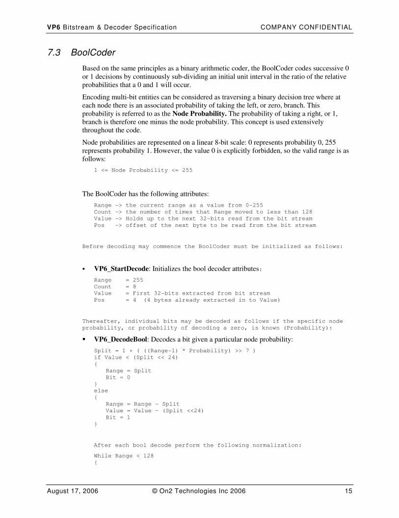
7.3 BoolCoder
Based on the same principles as a binary arithmetic coder, the BoolCoder codes successive 0
or 1 decisions by continuously sub-dividing an initial unit interval in the ratio of the relative
probabilities that a 0 and 1 will occur.
Encoding multi-bit entities can be considered as traversing a binary decision tree where at
each node there is an associated probability of taking the left, or zero, branch. This
probability is referred to as the Node Probability. The probability of taking a right, or 1,
branch is therefore one minus the node probability. This concept is used extensively
throughout the code.
Node probabilities are represented on a linear 8-bit scale: 0 represents probability 0, 255
represents probability 1. However, the value 0 is explicitly forbidden, so the valid range is as
follows:
1 <= Node Probability <= 255
The BoolCoder has the following attributes:
Range -> the current range as a value from 0-255
Count -> the number of times that Range moved to less than 128
Value -> Holds up to the next 32-bits read from the bit stream
Pos -> offset of the next byte to be read from the bit stream
Before decoding may commence the BoolCoder must be initialized as follows:
� VP6_StartDecode: Initializes the bool decoder attributes:
Range = 255
Count = 8
Value = First 32-bits extracted from bit stream
Pos = 4 (4 bytes already extracted in to Value)
Thereafter, individual bits may be decoded as follows if the specific node
probability, or probability of decoding a zero, is known (Probability):
� VP6_DecodeBool: Decodes a bit given a particular node probability:
Split = 1 + ( ((Range-1) * Probability) >> 7 )
if Value < (Split << 24)
{
Range = Split
Bit = 0
}
else
{
Range = Range - Split
Value = Value – (Split <<24)
Bit = 1
}
After each bool decode perform the following normalization:
While Range < 128
{
VP6 Bitstream & Decoder Specif ication COMPANY CONFIDENTIAL
August 17, 2006 © On2 Technologies Inc 2006 16
Range *= 2
Value *= 2
Count --
if Count == 0
{
// Bits = extract byte from bitstream at position Pos
Value = Value | Bits
Pos ++
Count = 8
}
}
Return Bit
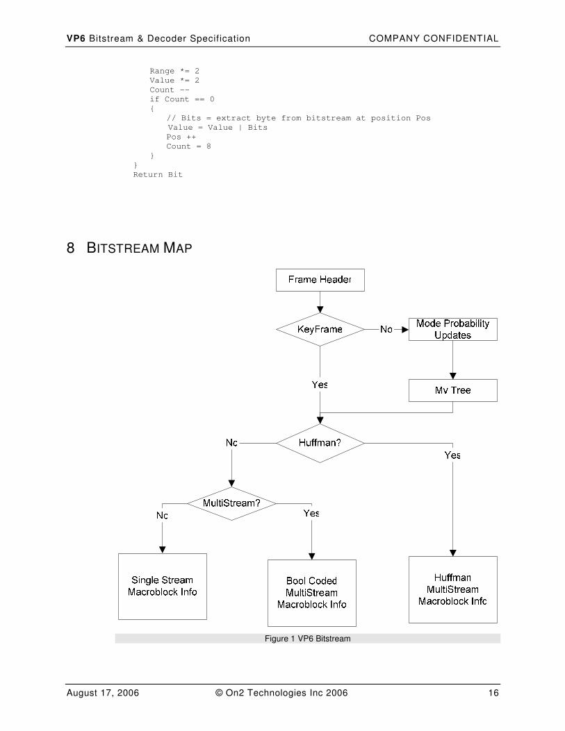
8 BITSTREAM MAP
Figure 1 VP6 Bitstream
VP6 Bitstream & Decoder Specif ication COMPANY CONFIDENTIAL
August 17, 2006 © On2 Technologies Inc 2006 17
Please refer to the following sections for more information:
• Frame Header (See Section 9).
• Mode Probability Updates (See Section 10).
• Mv Tree (See Section 11).
• Single Stream Macroblock Info (See Figure 2).
• Bool Coded MultiStream Macroblock Info (See Figure 3).
• Huffman MultiStream Macroblock Info (See Figure 4).
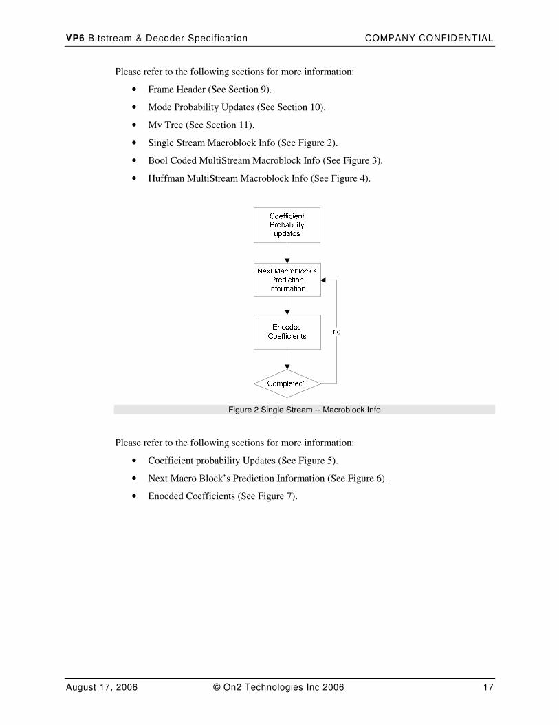
Figure 2 Single Stream -- Macroblock Info
Please refer to the following sections for more information:
• Coefficient probability Updates (See Figure 5).
• Next Macro Block’s Prediction Information (See Figure 6).
• Enocded Coefficients (See Figure 7).
VP6 Bitstream & Decoder Specif ication COMPANY CONFIDENTIAL
August 17, 2006 © On2 Technologies Inc 2006 18
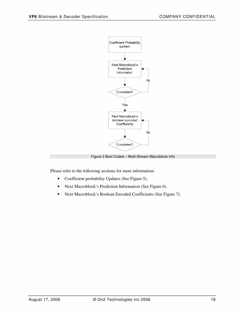
Figure 3 Bool Coded – Multi-Stream Macroblock Info
Please refer to the following sections for more information:
• Coefficient probability Updates (See Figure 5).
• Next Macroblock’s Prediction Information (See Figure 6).
• Next Macroblock’s Boolean Encoded Coefficients (See Figure 7).
VP6 Bitstream & Decoder Specif ication COMPANY CONFIDENTIAL
August 17, 2006 © On2 Technologies Inc 2006 19
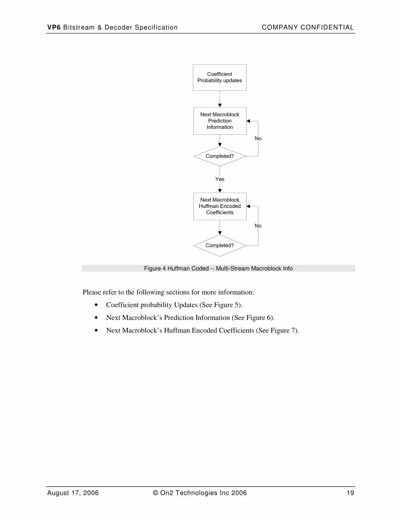
Coefficient Probability updates
Next Macroblock Prediction Information
Next Macroblock Huffman Encoded
Coefficients
Completed?
Completed?
Yes
No
No
Figure 4 Huffman Coded -- Multi-Stream Macroblock Info
Please refer to the following sections for more information:
• Coefficient probability Updates (See Figure 5).
• Next Macroblock’s Prediction Information (See Figure 6).
• Next Macroblock’s Huffman Encoded Coefficients (See Figure 7).
VP6 Bitstream & Decoder Specif ication COMPANY CONFIDENTIAL
August 17, 2006 © On2 Technologies Inc 2006 20
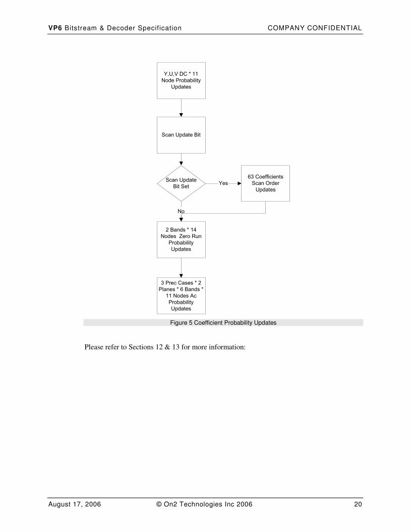
Y,U,V DC * 11
Node Probability
Updates
Scan Update
Bit Set
63 Coefficients
Scan Order
Updates
2 Bands * 14
Nodes Zero Run
Probability
Updates
3 Prec Cases * 2
Planes * 6 Bands *
11 Nodes Ac
Probability
Updates
No
Yes
Scan Update Bit
Figure 5 Coefficient Probability Updates
Please refer to Sections 12 & 13 for more information:
VP6 Bitstream & Decoder Specif ication COMPANY CONFIDENTIAL
August 17, 2006 © On2 Technologies Inc 2006 21
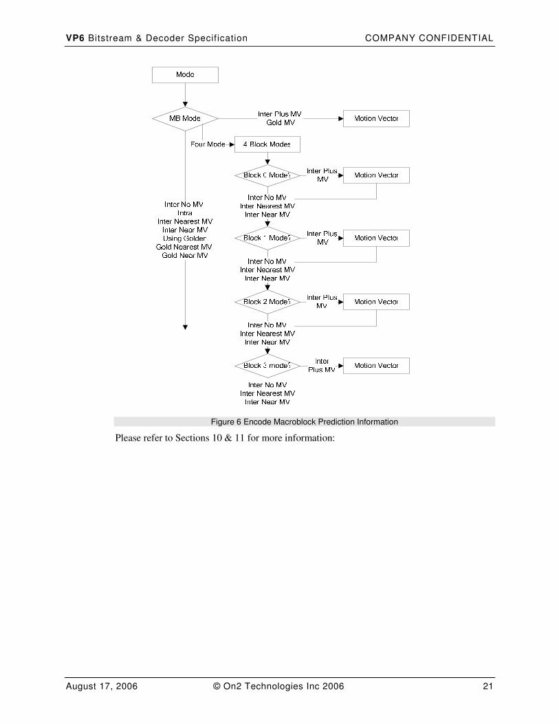
Figure 6 Encode Macroblock Prediction Information
Please refer to Sections 10 & 11 for more information:
VP6 Bitstream & Decoder Specif ication COMPANY CONFIDENTIAL
August 17, 2006 © On2 Technologies Inc 2006 22
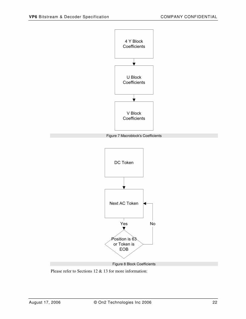
4 Y Block
Coefficients
U Block
Coefficients
V Block
Coefficients
Figure 7 Macroblock's Coefficients
DC Token
Next AC Token
Position is 63
or Token is
EOB
Yes No
Figure 8 Block Coefficients
Please refer to Sections 12 & 13 for more information:
VP6 Bitstream & Decoder Specif ication COMPANY CONFIDENTIAL
August 17, 2006 © On2 Technologies Inc 2006 23
9 FRAME HEADER
The initial bytes of the compressed frame define a header containing the following:
Field Type Notes
FrameType R(1) 0 for I-Frame, 1 for P-Frame.
DctQMask R(6) Quantizer setting for the frame.
MultiStream R(1) 0 for One partition, 1 for two partitions.
IntraHeader || InterHeader See tables
2 & 3
If FrameType==0 : IntraHeader
If FrameType==1 : InterHeader
UseHuffman b(1) 0 for BoolCoder, 1 for Huffman Coder for 2nd
data
partition.
Table 1 Frame Header
FrameType. An individual frame is encoded as either as an I- or P-frame. An I-frame, or
intra-frame, is an atomic unit meaning that it can be completely decoded without reference to
any previously decoded frame. A P-frame, or inter-frame, is coded differentially with respect
to a prediction frame that is constructed from previously decoded reference frames and is not
therefore an atomic unit. Each MB in the prediction frame is formed by using Motion
Compensation, unless the MB is coded in intra-mode in which case no prediction is required.
Two reference frames are defined: the last reconstructed frame and a previously decoded
frame known as the Golden Frame.
It should be noted that VP6 makes no use of backward or bi-directional prediction.
Specifically, there is no equivalent to the MPEG B-frame.
DctQMask. VP6 uses a 64 level linear quantizer, the particular quantizer level for a frame
being specified as a 6-bit index, DctQMask, into a table that specifies the corresponding bin-
width. The value 63 represents the most accurate quantizer level, 0 represents the least
accurate. Intermediate values are specified to give very roughly linear changes in data rate.
MultiStream. The MultiStream flag indicates whether the bitstream is split between one (0)
or two (1) partitions. The bitstream may optionally be split between two partitions, in
addition to the frame header. The first partition contains coding mode information and motion
vectors, the second partition contains the tokenized, quantized, DCT coded prediction error
information.
UseHuffman. When using two bitstream partitions (MultiStream set to 1) the second
partition may optionally use Huffman (1) rather than Boolean Coding (0) techniques. This
can help to reduce the computational load in both encoder and decoder at high data rates on
low to medium power processors.
Field Type Notes
Vp3VersionNo R(5) Version of encoder used to encode frame.

VP6 Bitstream & Decoder Specif ication COMPANY CONFIDENTIAL
August 17, 2006 © On2 Technologies Inc 2006 24
VpProfile R(2) 0 Simple, 3 Advanced (1 and 2 undefined)
(Reserved) R(1) Currently unused; always 0
Buff2Offset R(16) Offset to 2nd
partition. If (MultiStream == 1) ||
(SIMPLE_PROFILE == 1).
VFragments b(8) Number of rows of 8x8 blocks in un-scaled decoded
image.
HFragments b(8) Number of cols of 8x8 blocks in un-scaled decoded
image.
OutputVFragments b(8) Number of rows of 8x8 blocks in scaled output image.
OutputHFragments b(8) Number of cols of 8x8 blocks in scaled output image.
ScalingMode b(2) Mode to use for scaling decoded image.
AutoSelectPMFlag b(1) ADVANCED _PROFILE (VpProfile == 3) only:
0 Prediction filter type is fixed and will be specified,
1 Auto-select bi-cubic or bi-linear prediction filter.
PredictionFilterVarThresh b(5) If AutoSelectPMFlag == 1 only:
Threshold on prediction filter variance.
PredictionFilterMvSizeThresh b(3) If AutoSelectPMFlag == 1 only:
Threshold on MV size to use prediction filter for.
BiCubicOrBiLinearFiltFlag b(1) If AutoSelectPMFlag == 0 only:
0 Use Bi-linear prediction filter,
1 Use Bi-Cubic prediction filter.
PredictionFilterAlpha b(4) Vp3VersionNo == 8 (VP6.2) only:
Selector to choose bicubic filter
coefficients
Table 2 IntraHeader Definition
Vp3VersionNo. Identifies the bitstream as being compliant with a particular VPx decoder
format. The values 6,7, and 8 represent VP6.0, VP6.1, and VP6.2 bitsreams, respectively. The
decoder should check this field to ensure that it can decode the bitstream.
VpProfile. Two coding profiles are currently defined, SIMPLE and ADVANCED, each
specifying the use of a set of coding tools.
Reserved. This bit has no meaning when decoding the bitstream. It remains for historical
reasons, and must be consumed during decoding.
Buff2Offset. Specifies the offset of the second bitstream partition from the start of the frame
buffer in bytes. Only present if MultiStream flag indicates that two bitstream partitions are
being used.
VFragments. The vertical coded height of the frame in 8x8 block units. If image is 240
pixels high, VFragments will be 30.
VP6 Bitstream & Decoder Specif ication COMPANY CONFIDENTIAL
August 17, 2006 © On2 Technologies Inc 2006 25
HFragments. The horizontal coded width of the frame in 8x8 block units. If image is 320
pixels wide, HFragments will be 40.
OutputVFragments. The vertical decoded height of the frame as it should be scaled on
output in 8x8 block units. See definition of ScalingMode below.
OutputHFragments. The horizontal decoded width of the frame as it should be scaled on
output in 8x8 block units. See definition of ScalingMode below.
ScalingMode. Internally a frame may be encoded at a different resolution to the eventual size
that it is presented on output from the decoder. There are four ways to scale the frame on
output MAINTAIN_ASPECT_RATIO, SCALE_TO_FIT, CENTER, OTHER.
AutoSelectPMFlag. Indicates what filter type will be used to generate interpolated sub-pixel
motion compensated prediction blocks; Bi-linear and Bi-cubic filters are defined. Value 0
indicates that filter type is fixed and will be specified in field BiCubicOrBiLinearFiltFlag.
Value 1 turns on automatic selection of filter type using the two thresholds
PredictionFilterVarThresh and PredictionFilterMvSizeThresh. Present only if frame coded
using Advanced Profile.
PredictionFilterVarThresh. Variance threshold at or above which the bi-cubic motion-
compensated interpolation filter will be used, otherwise bi-linear filter is used. Value 0
indicates that the bi-cubic filter will always be used. Present only if AutoSelectPMFlag is 1.
PredictionFilterMvSizeThresh. Used to set largest MV magnitude at which the bi-cubic
filter is used, otherwise bi-linear filter is used. Largest MV component, in whole pixel units,
for use of bi-cubic filter is (1 << (PredictionFilterMvSizeThresh – 1)). Present only if
AutoSelectPMFlag is 1.
BiCubicOrBiLinearFiltFlag. Selects specific filter type for producing interpolated sub-pixel
motion compensated prediction blocks. Present only if AutoSelectPMFlag is 0.
PredictionFilterAlpha. Specifies the index into the BicubicFilterSet table to use when
retrieving filter coeffiecients. In general, these coeffiecents control the sharpness of the filter.
Present only if Vp3VersionNo == 8 (VP6.2 bitstreams only)
Field Type Notes
Buff2Offset R(16) Offset to 2nd
partition. If (MultiStream == 1) ||
(SIMPLE_PROFILE == 1).
RefreshGoldenFrame b(1) 0 Do not update the Golden Frame with this frame,
1 Decoded frame should become new Golden Frame.
UseLoopFilter b(1) ADVANCED_PROFILE only:
0 Disable the loop-filter, 1 Enable the loop-filter.
LoopFilterSelector b(1) UseLoopFilter==1 only:
0 Basic loop filter, 1 De-ringing loop-filter (see
below).
AutoSelectPMFlag b(1) If Vp3VersionNo == 8 (VP6.2)
and ADVANCED _PROFILE (VpProfile == 3) only:
0 Prediction filter type is fixed and will be specified,
1 Auto-select bi-cubic or bi-linear prediction filter.
VP6 Bitstream & Decoder Specif ication COMPANY CONFIDENTIAL
August 17, 2006 © On2 Technologies Inc 2006 26
PredictionFilterVarThresh b(5) If Vp3VersionNo == 8 (VP6.2)
and AutoSelectPMFlag == 1 only:
Threshold on prediction filter variance.
PredictionFilterMvSizeThresh b(3) If Vp3VersionNo == 8 (VP6.2)
and AutoSelectPMFlag == 1 only:
Threshold on MV size to use prediction filter for.
BiCubicOrBiLinearFiltFlag b(1) If Vp3VersionNo == 8 (VP6.2)
and AutoSelectPMFlag == 0 only:
0 Use Bi-linear prediction filter,
1 Use Bi-Cubic prediction filter.
PredictionFilterAlpha b(4) Vp3VersionNo == 8 (VP6.2) only:
Selector to choose bicubic filter
coefficients
Table 3 InterHeader Definition
Buff2Offset. Specifies the offset of the second bitstream partition from the start of the frame
buffer in bytes. Only present if MultiStream flag indicates that two bitstream partitions are
being used.
RefreshGoldenFrame. Flag indicating whether the current frame, once fully decoded,
should be used to update the alternative prediction frame known as the Golden Frame. If set
to 1 the decoded frame becomes the new Golden Frame. Otherwise the existing Golden
Frame persists.
UseLoopFilter. Flags whether the loop-filter should be used for this frame. Present only if
frame coded using Advanced Profile.
LoopFilterSelector. Selects which loop filter to use for this frame, 0 indicates use of a basic
de-blocking filter, 1 indicates use of a more complex de-blocking & de-ringing filter. Present
only if UseLoopFilter set to 1.
Note: Although supported by the bitstream the de-ringing version of the loop-filter is NOT
currently defined in the VP6 decoder specification. Therefore, at the current time it is
mandated that where the loop-filter is used the field LoopFilterSelector must be set to the
value 0.
AutoSelectPMFlag. Indicates what filter type will be used to generate interpolated sub-pixel
motion compensated prediction blocks; Bi-linear and Bi-cubic filters are defined. Value 0
indicates that filter type is fixed and will be specified in field BiCubicOrBiLinearFiltFlag.
Value 1 turns on automatic selection of filter type using the two thresholds
PredictionFilterVarThresh and PredictionFilterMvSizeThresh. Present only if frame coded
using Advanced Profile. Present only in VP6.2 bitstreams (Vp3VersionNo == 8).
PredictionFilterVarThresh. Variance threshold at or above which the bi-cubic motion-
compensated interpolation filter will be used, otherwise bi-linear filter is used. Value 0
indicates that the bi-cubic filter will always be used. Present only if AutoSelectPMFlag is 1.
Present only in VP6.2 bitstreams (Vp3VersionNo == 8).
PredictionFilterMvSizeThresh. Used to set largest MV magnitude at which the bi-cubic
filter is used, otherwise bi-linear filter is used. Largest MV component, in whole pixel units,
VP6 Bitstream & Decoder Specif ication COMPANY CONFIDENTIAL
August 17, 2006 © On2 Technologies Inc 2006 27
for use of bi-cubic filter is (1 << (PredictionFilterMvSizeThresh – 1)). Present only if
AutoSelectPMFlag is 1. Present only in VP6.2 bitstreams (Vp3VersionNo == 8).
BiCubicOrBiLinearFiltFlag. Selects specific filter type for producing interpolated sub-pixel
motion compensated prediction blocks. Present only if AutoSelectPMFlag is 0. Present only
in VP6.2 bitstreams (Vp3VersionNo == 8).
PredictionFilterAlpha. Specifies the index into the BicubicFilterSet table to use when
retrieving filter coeffiecients. In general, these coeffiecents control the sharpness of the filter.
Present only if Vp3VersionNo == 8 (VP6.2 bitstreams only).
10 MODE DECODING
For I-frames each MB is implicitly encoded in intra-mode so no signaling of mode is
required.
For P-frames, each MB in the frame has an associated Coding Mode indicating to the decoder
the method by which the MB prediction, if any, is constructed. VP6 defines ten possible
coding modes.
Coding Mode Prediction Frame MV
CODE_INTER_NO_MV Previous frame reconstruction. Fixed: (0,0).
CODE_INTRA None. None.
CODE_INTER_PLUS_MV Previous frame reconstruction. Newly calculated MV.
CODE_INTER_NEAREST_MV Previous frame reconstruction. Same MV as Nearest
block.
CODE_INTER_NEAR_MV Previous frame reconstruction. Same MV as Near block.
CODE_USING_GOLDEN Golden Frame. Fixed: (0,0).
CODE_GOLDEN_MV Golden Frame. Newly calculated MV.
CODE_INTER_FOURMV Previous frame reconstruction. Each of the four luma-
blocks has associated MV.
CODE_GOLD_NEAREST_MV Golden Frame. Same MV as Nearest
block.
CODE_GOLD_NEAR_MV Golden Frame. Same MV as Near block.
Table 4 Coding Modes
CODE_INTRA mode uses no prediction, each of its six blocks is forward DCT encoded after
the fixed value 128 is subtracted from each sample value (this improves DCT accuracy).
The nine remaining modes use motion compensation to derive a prediction for the MB. Two
parameters specify the best match for a MB (or block for mode CODE_INTER_FOURMV),
a motion vector and an indication of which reference frame the vector refers to (either the
VP6 Bitstream & Decoder Specif ication COMPANY CONFIDENTIAL
August 17, 2006 © On2 Technologies Inc 2006 28
previous reconstructed frame or the Golden frame). The motion vector is specified in ¼ pixel
units (i.e. ¼ sample precision for luma and 1/8 sample precision for chroma).
The maximum magnitude of a MV component is 31 ¾ whole pixels (127 in units of ¼ pixel).
If a MB has coding mode CODE_INTER_FOURMV then each of its four Y-blocks will be
coded independently, each having an associated coding mode from a reduced set that
excludes intra or any of the Golden Frame modes. In this case the motion vector for the two
chroma blocks is computed by averaging the four Y vectors (rounding away from zero).
In certain circumstances it is much more efficient to specify that a MB has the same MV as
one of its nearest neighbors, rather than coding a new MV. For this reason VP6 defines the
concept of the Nearest Motion Vector and Near Motion Vector, as the first 2 non (0,0)
MVs encountered when traversing, in order, a list of the twelve spatially nearest decoded
macroblock neighbors (the list is described by offsets from the present macroblock defined in
the array NearMacroblocks below), that are encoded with reference to the same prediction
frame as the current block. If no such blocks exist in the list then Nearest and Near MVs are
undefined.
So, for example, the coding mode CODE_GOLD_NEAREST_MV implies that the MV for
the current MB should be set to the same vector as that specified for the Nearest block that
used the Golden Frame prediction frame.
In the following table the pairs of data values refer to {row, column} offsets in MacroBlock
units:
NearMacroBlocks[12] =
{
{ -1, 0 },
{ 0, -1 },
{ -1, -1 },
{ -1, 1 },
{ -2, 0 },
{ 0, -2 },
{ -1, -2 },
{ -2, -1 },
{ -2, 1 },
{ -1, 2 },
{ -2, -2 },
{ -2, 2 }
}
The BoolCoder is used to decode coding modes using a two dimensional contextual table as
follows:
probXmitted [3][20]
This table should be maintained by the decoder. It contains probabilities that any of the 10
modes will be the next mode decoded in the bitstream given the following situations:
The first dimension of this probXmitted array is indexed by contextual information
regarding whether or not all of the modes are available for use as follows:
VP6 Bitstream & Decoder Specif ication COMPANY CONFIDENTIAL
August 17, 2006 © On2 Technologies Inc 2006 29
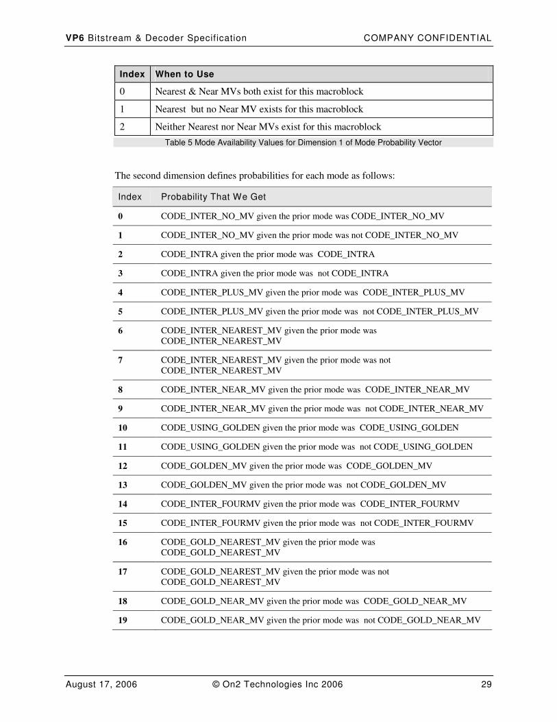
Index When to Use
0 Nearest & Near MVs both exist for this macroblock
1 Nearest but no Near MV exists for this macroblock
2 Neither Nearest nor Near MVs exist for this macroblock
Table 5 Mode Availability Values for Dimension 1 of Mode Probability Vector
The second dimension defines probabilities for each mode as follows:
Index Probability That We Get
0 CODE_INTER_NO_MV given the prior mode was CODE_INTER_NO_MV
1 CODE_INTER_NO_MV given the prior mode was not CODE_INTER_NO_MV
2 CODE_INTRA given the prior mode was CODE_INTRA
3 CODE_INTRA given the prior mode was not CODE_INTRA
4 CODE_INTER_PLUS_MV given the prior mode was CODE_INTER_PLUS_MV
5 CODE_INTER_PLUS_MV given the prior mode was not CODE_INTER_PLUS_MV
6 CODE_INTER_NEAREST_MV given the prior mode was
CODE_INTER_NEAREST_MV
7 CODE_INTER_NEAREST_MV given the prior mode was not
CODE_INTER_NEAREST_MV
8 CODE_INTER_NEAR_MV given the prior mode was CODE_INTER_NEAR_MV
9 CODE_INTER_NEAR_MV given the prior mode was not CODE_INTER_NEAR_MV
10 CODE_USING_GOLDEN given the prior mode was CODE_USING_GOLDEN
11 CODE_USING_GOLDEN given the prior mode was not CODE_USING_GOLDEN
12 CODE_GOLDEN_MV given the prior mode was CODE_GOLDEN_MV
13 CODE_GOLDEN_MV given the prior mode was not CODE_GOLDEN_MV
14 CODE_INTER_FOURMV given the prior mode was CODE_INTER_FOURMV
15 CODE_INTER_FOURMV given the prior mode was not CODE_INTER_FOURMV
16 CODE_GOLD_NEAREST_MV given the prior mode was
CODE_GOLD_NEAREST_MV
17 CODE_GOLD_NEAREST_MV given the prior mode was not
CODE_GOLD_NEAREST_MV
18 CODE_GOLD_NEAR_MV given the prior mode was CODE_GOLD_NEAR_MV
19 CODE_GOLD_NEAR_MV given the prior mode was not CODE_GOLD_NEAR_MV
VP6 Bitstream & Decoder Specif ication COMPANY CONFIDENTIAL
August 17, 2006 © On2 Technologies Inc 2006 30
Table 6 ProbabilitySituation Table
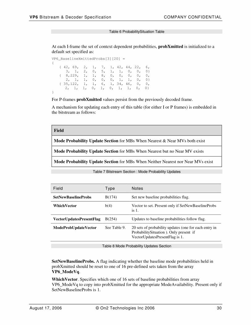
At each I-frame the set of context dependent probabilities, probXmitted is initialized to a
default set specified as:
VP6_BaselineXmittedProbs[3][20] =
{
{ 42, 69, 2, 1, 7, 1, 42, 44, 22, 6,
3, 1, 2, 0, 5, 1, 1, 0, 0, 0}
{ 8,229, 1, 1, 8, 0, 0, 0, 0, 0,
2, 1, 1, 0, 0, 0, 1, 1, 0, 0}
{ 35,122, 1, 1, 6, 1, 34, 46, 0, 0,
2, 1, 1, 0, 1, 0, 1, 1, 0, 0}
}
For P-frames probXmitted values persist from the previously decoded frame.
A mechanism for updating each entry of this table (for either I or P frames) is embedded in
the bitstream as follows:
Field
Mode Probability Update Section for MBs When Nearest & Near MVs both exist
Mode Probability Update Section for MBs When Nearest but no Near MV exists
Mode Probability Update Section for MBs When Neither Nearest nor Near MVs exist
Table 7 Bitstream Section : Mode Probability Updates
Field Type Notes
SetNewBaselineProbs B(174) Set new baseline probabilities flag.
WhichVector b(4) Vector to set. Present only if SetNewBaselineProbs
is 1.
VectorUpdatesPresentFlag B(254) Updates to baseline probabilities follow flag.
ModeProbUpdateVector See Table 9. 20 sets of probability updates (one for each entry in
ProbabilitySituation ). Only present if
VectorUpdatesPresentFlag is 1.
Table 8 Mode Probability Updates Section
SetNewBaselineProbs. A flag indicating whether the baseline mode probabilities held in
probXmitted should be reset to one of 16 pre-defined sets taken from the array
VP6_ModeVq.
WhichVector. Specifies which one of 16 sets of baseline probabilities from array
VP6_ModeVq to copy into probXmitted for the appropriate ModeAvailability. Present only if
SetNewBaselineProbs is 1.

VP6 Bitstream & Decoder Specif ication COMPANY CONFIDENTIAL
August 17, 2006 © On2 Technologies Inc 2006 31
VectorUpdatesPresentFlag. Indicates whether updates to the baseline probabilities follow.
ModeProbUpdateVector. 20 sets of probability updates (one for each entry in
ProbabilitySituation ). Only present if Vector UpdatesPresentFlag is 1.)
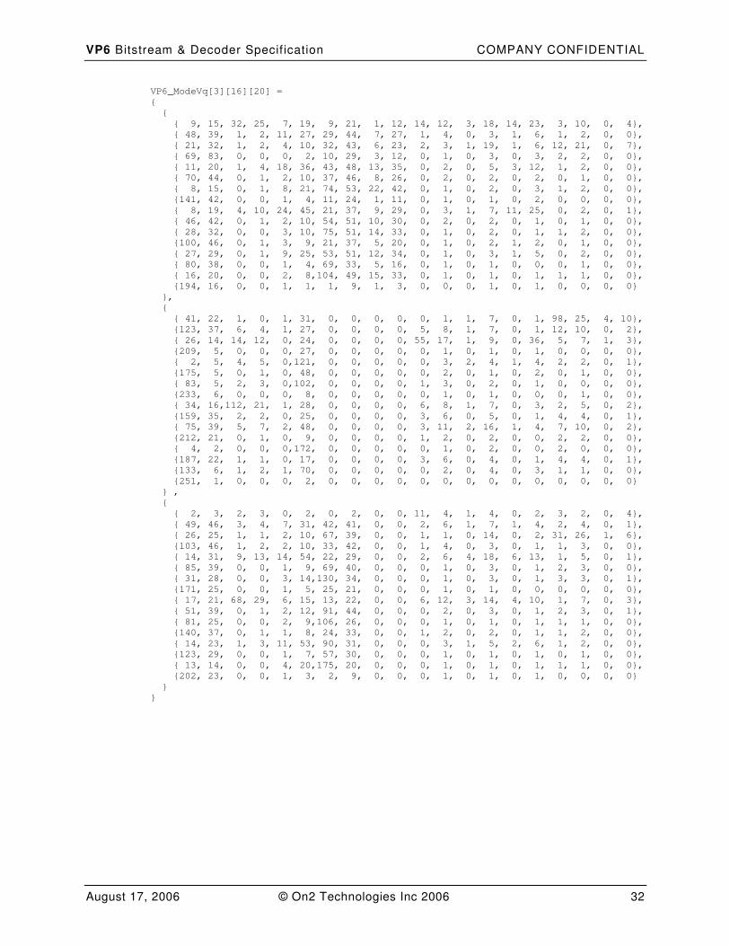
Note: VP6_modeVq is a 3 dimensional index the first dimension is the ModeAvailability
(Nearest & Near MVs both exist , Nearest but no Near MV exists , Neither Nearest nor Near
MV exists). WhichVector is an index into the second dimension of this array. The 20
element vector specified by whichVector is copied into the probXmitted table for the
appropriate ModeAvailability.
VP6 Bitstream & Decoder Specif ication COMPANY CONFIDENTIAL
August 17, 2006 © On2 Technologies Inc 2006 32
VP6_ModeVq[3][16][20] =
{
{
{ 9, 15, 32, 25, 7, 19, 9, 21, 1, 12, 14, 12, 3, 18, 14, 23, 3, 10, 0, 4},
{ 48, 39, 1, 2, 11, 27, 29, 44, 7, 27, 1, 4, 0, 3, 1, 6, 1, 2, 0, 0},
{ 21, 32, 1, 2, 4, 10, 32, 43, 6, 23, 2, 3, 1, 19, 1, 6, 12, 21, 0, 7},
{ 69, 83, 0, 0, 0, 2, 10, 29, 3, 12, 0, 1, 0, 3, 0, 3, 2, 2, 0, 0},
{ 11, 20, 1, 4, 18, 36, 43, 48, 13, 35, 0, 2, 0, 5, 3, 12, 1, 2, 0, 0},
{ 70, 44, 0, 1, 2, 10, 37, 46, 8, 26, 0, 2, 0, 2, 0, 2, 0, 1, 0, 0},
{ 8, 15, 0, 1, 8, 21, 74, 53, 22, 42, 0, 1, 0, 2, 0, 3, 1, 2, 0, 0},
{141, 42, 0, 0, 1, 4, 11, 24, 1, 11, 0, 1, 0, 1, 0, 2, 0, 0, 0, 0},
{ 8, 19, 4, 10, 24, 45, 21, 37, 9, 29, 0, 3, 1, 7, 11, 25, 0, 2, 0, 1},
{ 46, 42, 0, 1, 2, 10, 54, 51, 10, 30, 0, 2, 0, 2, 0, 1, 0, 1, 0, 0},
{ 28, 32, 0, 0, 3, 10, 75, 51, 14, 33, 0, 1, 0, 2, 0, 1, 1, 2, 0, 0},
{100, 46, 0, 1, 3, 9, 21, 37, 5, 20, 0, 1, 0, 2, 1, 2, 0, 1, 0, 0},
{ 27, 29, 0, 1, 9, 25, 53, 51, 12, 34, 0, 1, 0, 3, 1, 5, 0, 2, 0, 0},
{ 80, 38, 0, 0, 1, 4, 69, 33, 5, 16, 0, 1, 0, 1, 0, 0, 0, 1, 0, 0},
{ 16, 20, 0, 0, 2, 8,104, 49, 15, 33, 0, 1, 0, 1, 0, 1, 1, 1, 0, 0},
{194, 16, 0, 0, 1, 1, 1, 9, 1, 3, 0, 0, 0, 1, 0, 1, 0, 0, 0, 0}
},
{
{ 41, 22, 1, 0, 1, 31, 0, 0, 0, 0, 0, 1, 1, 7, 0, 1, 98, 25, 4, 10},
{123, 37, 6, 4, 1, 27, 0, 0, 0, 0, 5, 8, 1, 7, 0, 1, 12, 10, 0, 2},
{ 26, 14, 14, 12, 0, 24, 0, 0, 0, 0, 55, 17, 1, 9, 0, 36, 5, 7, 1, 3},
{209, 5, 0, 0, 0, 27, 0, 0, 0, 0, 0, 1, 0, 1, 0, 1, 0, 0, 0, 0},
{ 2, 5, 4, 5, 0,121, 0, 0, 0, 0, 0, 3, 2, 4, 1, 4, 2, 2, 0, 1},
{175, 5, 0, 1, 0, 48, 0, 0, 0, 0, 0, 2, 0, 1, 0, 2, 0, 1, 0, 0},
{ 83, 5, 2, 3, 0,102, 0, 0, 0, 0, 1, 3, 0, 2, 0, 1, 0, 0, 0, 0},
{233, 6, 0, 0, 0, 8, 0, 0, 0, 0, 0, 1, 0, 1, 0, 0, 0, 1, 0, 0},
{ 34, 16,112, 21, 1, 28, 0, 0, 0, 0, 6, 8, 1, 7, 0, 3, 2, 5, 0, 2},
{159, 35, 2, 2, 0, 25, 0, 0, 0, 0, 3, 6, 0, 5, 0, 1, 4, 4, 0, 1},
{ 75, 39, 5, 7, 2, 48, 0, 0, 0, 0, 3, 11, 2, 16, 1, 4, 7, 10, 0, 2},
{212, 21, 0, 1, 0, 9, 0, 0, 0, 0, 1, 2, 0, 2, 0, 0, 2, 2, 0, 0},
{ 4, 2, 0, 0, 0,172, 0, 0, 0, 0, 0, 1, 0, 2, 0, 0, 2, 0, 0, 0},
{187, 22, 1, 1, 0, 17, 0, 0, 0, 0, 3, 6, 0, 4, 0, 1, 4, 4, 0, 1},
{133, 6, 1, 2, 1, 70, 0, 0, 0, 0, 0, 2, 0, 4, 0, 3, 1, 1, 0, 0},
{251, 1, 0, 0, 0, 2, 0, 0, 0, 0, 0, 0, 0, 0, 0, 0, 0, 0, 0, 0}
} ,
{
{ 2, 3, 2, 3, 0, 2, 0, 2, 0, 0, 11, 4, 1, 4, 0, 2, 3, 2, 0, 4},
{ 49, 46, 3, 4, 7, 31, 42, 41, 0, 0, 2, 6, 1, 7, 1, 4, 2, 4, 0, 1},
{ 26, 25, 1, 1, 2, 10, 67, 39, 0, 0, 1, 1, 0, 14, 0, 2, 31, 26, 1, 6},
{103, 46, 1, 2, 2, 10, 33, 42, 0, 0, 1, 4, 0, 3, 0, 1, 1, 3, 0, 0},
{ 14, 31, 9, 13, 14, 54, 22, 29, 0, 0, 2, 6, 4, 18, 6, 13, 1, 5, 0, 1},
{ 85, 39, 0, 0, 1, 9, 69, 40, 0, 0, 0, 1, 0, 3, 0, 1, 2, 3, 0, 0},
{ 31, 28, 0, 0, 3, 14,130, 34, 0, 0, 0, 1, 0, 3, 0, 1, 3, 3, 0, 1},
{171, 25, 0, 0, 1, 5, 25, 21, 0, 0, 0, 1, 0, 1, 0, 0, 0, 0, 0, 0},
{ 17, 21, 68, 29, 6, 15, 13, 22, 0, 0, 6, 12, 3, 14, 4, 10, 1, 7, 0, 3},
{ 51, 39, 0, 1, 2, 12, 91, 44, 0, 0, 0, 2, 0, 3, 0, 1, 2, 3, 0, 1},
{ 81, 25, 0, 0, 2, 9,106, 26, 0, 0, 0, 1, 0, 1, 0, 1, 1, 1, 0, 0},
{140, 37, 0, 1, 1, 8, 24, 33, 0, 0, 1, 2, 0, 2, 0, 1, 1, 2, 0, 0},
{ 14, 23, 1, 3, 11, 53, 90, 31, 0, 0, 0, 3, 1, 5, 2, 6, 1, 2, 0, 0},
{123, 29, 0, 0, 1, 7, 57, 30, 0, 0, 0, 1, 0, 1, 0, 1, 0, 1, 0, 0},
{ 13, 14, 0, 0, 4, 20,175, 20, 0, 0, 0, 1, 0, 1, 0, 1, 1, 1, 0, 0},
{202, 23, 0, 0, 1, 3, 2, 9, 0, 0, 0, 1, 0, 1, 0, 1, 0, 0, 0, 0}
}
}
VP6 Bitstream & Decoder Specif ication COMPANY CONFIDENTIAL
August 17, 2006 © On2 Technologies Inc 2006 33
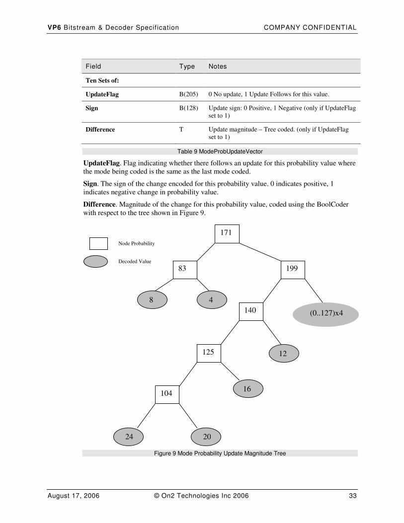
Field Type Notes
Ten Sets of:
UpdateFlag B(205) 0 No update, 1 Update Follows for this value.
Sign B(128) Update sign: 0 Positive, 1 Negative (only if UpdateFlag
set to 1)
Difference T Update magnitude – Tree coded. (only if UpdateFlag
set to 1)
Table 9 ModeProbUpdateVector
UpdateFlag. Flag indicating whether there follows an update for this probability value where
the mode being coded is the same as the last mode coded.
Sign. The sign of the change encoded for this probability value. 0 indicates positive, 1
indicates negative change in probability value.
Difference. Magnitude of the change for this probability value, coded using the BoolCoder
with respect to the tree shown in Figure 9.
Figure 9 Mode Probability Update Magnitude Tree
171
199
140
125
104
83
(0..127)x4
4 8
12
16
24 20
Node Probability
Decoded Value
VP6 Bitstream & Decoder Specif ication COMPANY CONFIDENTIAL
August 17, 2006 © On2 Technologies Inc 2006 34
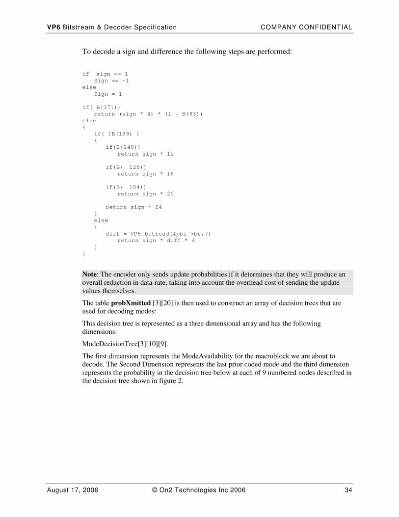
To decode a sign and difference the following steps are performed:
if sign == 1
Sign == -1
else
Sign = 1
if( B(171))
return (sign * 4) * (1 + B(83))
else
{
if( !B(199) )
{
if(B(140))
return sign * 12
if(B( 125))
return sign * 16
if(B( 104))
return sign * 20
return sign * 24
}
else
{
diff = VP6_bitread(&pbi->br,7)
return sign * diff * 4
}
}
Note: The encoder only sends update probabilities if it determines that they will produce an
overall reduction in data-rate, taking into account the overhead cost of sending the update
values themselves.
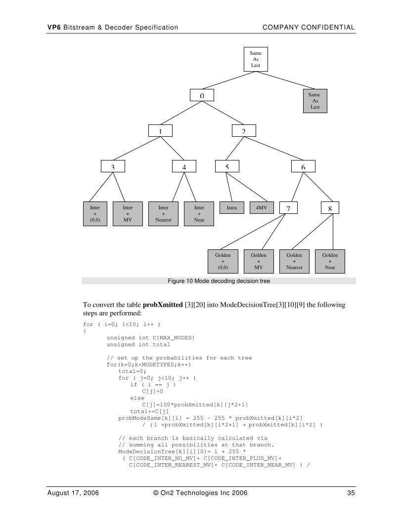
The table probXmitted [3][20] is then used to construct an array of decision trees that are
used for decoding modes:
This decision tree is represented as a three dimensional array and has the following
dimensions:
ModeDecisionTree[3][10][9].
The first dimension represents the ModeAvailability for the macroblock we are about to
decode. The Second Dimension represents the last prior coded mode and the third dimension
represents the probability in the decision tree below at each of 9 numbered nodes described in
the decision tree shown in figure 2.
VP6 Bitstream & Decoder Specif ication COMPANY CONFIDENTIAL
August 17, 2006 © On2 Technologies Inc 2006 35
Figure 10 Mode decoding decision tree
To convert the table probXmitted [3][20] into ModeDecisionTree[3][10][9] the following
steps are performed:
for ( i=0; i<10; i++ )
{
unsigned int C[MAX_MODES]
unsigned int total
// set up the probabilities for each tree
for(k=0;k<MODETYPES;k++)
total=0;
for ( j=0; j<10; j++ )
if ( i == j )
C[j]=0
else
C[j]=100*probXmitted[k][j*2+1]
total+=C[j]
probModeSame[k][i] = 255 - 255 * probXmitted[k][i*2]
/ ( 1 +probXmitted[k][i*2+1] + probXmitted[k][i*2] )
// each branch is basically calculated via
// summing all possibilities at that branch.
ModeDecisionTree[k][i][0]= 1 + 255 *
( C[CODE_INTER_NO_MV]+ C[CODE_INTER_PLUS_MV]+
C[CODE_INTER_NEAREST_MV]+ C[CODE_INTER_NEAR_MV] ) /
0
1 2
5 6 3 4
Inter
+
Nearest
Intra 4MV 7 8 Inter
+
Near
Golden
+
(0,0)
Golden
+
MV
Golden
+
Nearest
Golden
+
Near
Same
As
Last
Same
As
Last
Inter
+
(0,0)
Inter
+
MV
VP6 Bitstream & Decoder Specif ication COMPANY CONFIDENTIAL
August 17, 2006 © On2 Technologies Inc 2006 36
( 1 + total);
ModeDecisionTree[k][i][1]= 1 + 255 *
( C[CODE_INTER_NO_MV]+ C[CODE_INTER_PLUS_MV] ) /
( 1 + C[CODE_INTER_NO_MV]+ C[CODE_INTER_PLUS_MV]+
C[CODE_INTER_NEAREST_MV]+ C[CODE_INTER_NEAR_MV])
ModeDecisionTree[k][i][2]= 1 + 255 *
(C[CODE_INTRA]+ C[CODE_INTER_FOURMV]) /
(1 + C[CODE_INTRA]+ C[CODE_INTER_FOURMV]+
C[CODE_USING_GOLDEN]+C[CODE_GOLDEN_MV]+
C[CODE_GOLD_NEAREST_MV]+ C[CODE_GOLD_NEAR_MV])
ModeDecisionTree[k][i][3]= 1 + 255 *
(C[CODE_INTER_NO_MV]) /
(1 +C[CODE_INTER_NO_MV]+ C[CODE_INTER_PLUS_MV])
ModeDecisionTree[k][i][4]= 1 + 255 *
(C[CODE_INTER_NEAREST_MV]) /
(1 + C[CODE_INTER_NEAREST_MV]+ C[CODE_INTER_NEAR_MV])
ModeDecisionTree[k][i][5]= 1 + 255 *
(C[CODE_INTRA]) /
( 1 + C[CODE_INTRA]+ C[CODE_INTER_FOURMV])
ModeDecisionTree[k][i][6]= 1 + 255 *
( C[CODE_USING_GOLDEN] + C[CODE_GOLDEN_MV] ) /
(1 +C[CODE_USING_GOLDEN]+ C[CODE_GOLDEN_MV]+
C[CODE_GOLD_NEAREST_MV]+ C[CODE_GOLD_NEAR_MV])
ModeDecisionTree[k][i][7]= 1 + 255 *
( C[CODE_USING_GOLDEN]) /
( 1 + C[CODE_USING_GOLDEN]+ C[CODE_GOLDEN_MV])
ModeDecisionTree[k][i][8]= 1 + 255 *
( C[CODE_GOLD_NEAREST_MV]) /
( 1 + C[CODE_GOLD_NEAREST_MV]+ C[CODE_GOLD_NEAR_MV])
}
}
}
The function VP6_DecodeMode decodes the coding mode for a MB by traversing the
decision tree defined in Figure 10. At the root node the decision made is whether the mode is
the same as that of the last coded MB. Thereafter -- if not the same as the last MB -- at each
node the decision to go down the left or right path is dictated by the next bit read from the
bitstream by the BoolCoder. The node probabilities are stored in an array, the node number in
the figure indicating the index at which the value for that node can be found.
This process is described using the following steps:
if ( B((probModeSame[type][lastmode]) )
mode = lastmode;
else
*Stats = ModeDecisionTree[type][lastmode]
if ( B((Stats[0]) )
if ( B((Stats[2]) )
if ( B((Stats[6]) )
if(B(Stats[8]))
mode = CODE_GOLD_NEAR_MV
else
mode = CODE_GOLD_NEAREST_MV
else
if(B(Stats[7])
VP6 Bitstream & Decoder Specif ication COMPANY CONFIDENTIAL
August 17, 2006 © On2 Technologies Inc 2006 37
mode = CODE_GOLDEN_MV
else
mode = CODE_USING_GOLDEN
else
mode = CODE_INTRA;
if ( B((Stats[5]) )
mode = CODE_INTER_FOURMV;
else
if ( B((Stats[1]) )
If (B((Stats[4])
Mode = CODE_INTER_NEAR_MV
else
mode = CODE_INTER_NEAREST_MV
else
if (B((Stats[3]))
mode = CODE_INTER_PLUS_MV
else
mode = CODE_INTER_NO_MV
return mode;
In the case where the MB is coded using mode CODE_INTER_FOURMV the specific
coding mode for each of the four blocks comes from a reduced set of four modes. In this case
the mode is coded as a fixed two bit codeword using the BoolCoder and a probability of 128
for each bit. The codewords are as follows:
Block Coding Mode Code
CODE_INTER_NO_MV 00
CODE_INTER_PLUS_MV 01
CODE_INTER_NEAREST_MV 10
CODE_INTER_NEAR_MV 11
Table 10 Block Coding Mode Signaling
11 MOTION VECTORS
VP6 supports ten MacroBlock coding modes (see Section 10) of which three are used for
explicitly coding “new” motion vectors:
• CODE_INTER_PLUS_MV : A new motion vector is coded with reference to the
previous frame reconstruction.
• CODE_GOLDEN_MV : A new motion vector is coded with reference to the Golden
frame reconstruction
• CODE_INTER_FOURMV : A different mode may to be specified for each of the
luma blocks from a subset of those available at the MacroBlock level (see Table 10).
Each block coded with mode CODE_INTER_PLUS_MV will have its own explicitly
coded motion vector.
VP6 Bitstream & Decoder Specif ication COMPANY CONFIDENTIAL
August 17, 2006 © On2 Technologies Inc 2006 38
A further six modes use implicit motion vectors
• CODE_INTER_NO_MV : Use the motion vector (0,0) applied to the previous frame
reconstruction.
• CODE_INTER_NEAREST_MV : Use the motion vector from a previously coded
nearest MacroBlock applied to the previous frame reconstruction.
• CODE_INTER_NEAR_MV :: Use the motion vector from a previously coded near
MacroBlock applied to the previous frame reconstruction
• CODE_USING_GOLDEN : Use the motion vector (0,0) applied to the Golden frame
reconstruction.
• CODE_GOLD_NEAREST_MV: Use the motion vector from a previously coded
nearest MacroBlock applied to the Golden frame reconstruction.
• CODE_GOLD_NEAR_MV: Use the motion vector from a previously coded near
MacroBlock applied to the Golden frame reconstruction.
A definition of nearest and near MacroBlocks and details of how these are derived can be
found in Section 10.
New motion vectors are coded differentially with respect to the motion vector of the nearest
MacroBlock that uses the same reference frame (either the previous frame reconstruction or
the Golden frame), if such a MacroBlock exists and it is either immediately to the left of or
immediately above the current MacroBlock. Otherwise, new motion vectors are coded
absolutely (this can be thought of as differential coded with respect to the vector (0,0)).
11.1 Decoding a Motion Vector
Each new motion vector comprises an x-component and a y-component. Each of these is
categorized as either a short vector or a long vector.
• A short vector is defined as a vector with a length that is less than 8 in ¼ pixel units.
• A long vector is defined as a vector with a length that is greater than or equal to 8
and less than or equal to 127 in ¼ pixel units.
Different entropy strategies are used for coding short vectors and long vectors.
VP6 Bitstream & Decoder Specif ication COMPANY CONFIDENTIAL
August 17, 2006 © On2 Technologies Inc 2006 39
When decoding a motion vector the X component is decoded first followed by the Y
component. The process of decoding a vector component is defined in the following table.
Field Type Notes
IsVectorShort B(x)
ShortVector T Only present if ( IsVectorShort == 1)
LongVector 7*B(x) Only present if (If IsVectorShort == 0)
LongVectorBit3 B(x) Only present if (IsVectorShort == 0) and if any of bits 4 to
7 are non-zero.
ReadSignBit B(x)
Table 11 Decoding a Motion Vector Component
IsVectorShort. A flag that defines whether the vector is a long vector or a short vector.
ShortVector. Only present if the vector is a short vector (IsVectorShort == 1). The short
vector is decoded by traversing a BoolCoded tree (see Figure 11)
LongVector. Only present if (IsVectorShort == 0). Bits 0 to 7 of a long vector (excluding bit
3) are read in the following order: 0,1,2,7,6,5,4.
LongVectorBit3: Only present if (IsVectorShort == 0) and at least one of bits 4 to 7 was
non-zero. Bit 3 is implicitly set to 1 if bits 4 to 7 are all zero as we already know that this is
not a short vector (i.e. its magnitude is >= 8).
ReadSignBit: The sign bit for the vector. If the sign bit is 1 then negate the vector (vector = -
vector).
For the purposes of description the following table defines data structures that are used to
hold the probability values that are used when decoding motion vector components.
Data Structure Notes
IsMvShortProbs[2] Stores the probabilities used to decode IsVectorShort for the x and
y components. (x=0, y=1)
ShortMvProbs[2][7] Stores the tree node probabilities used to decode short motion vector
components for x and y. (x=0, y=1 in first index)
MvSizeProbs[2][8] Stores the probabilities needed to decode long motion vector
components for x and y. (x=0, y=1 in first index)
MvSignProbs[2] Stores the probabilities used to decode the sign bit for the x and y
components. (x=0, y=1)
Table 12 Probability data structures used in decoding motion vectors
The default values for the data structures defined in Table 12 are as follows. Note that the
first index in each table specifies x or y where x=0 and y =1;
Default_IsMvShortProbs[2] = { 162, 164 } // x,y
Default_ShortMvProbs [2][7] =
VP6 Bitstream & Decoder Specif ication COMPANY CONFIDENTIAL
August 17, 2006 © On2 Technologies Inc 2006 40
{
{ 225, 146, 172, 147, 214, 39, 156 }, // x
{ 204, 170, 119, 235, 140, 230, 228 } // y
}
Default_MvSizeProbs [2][8]=
{
{ 247, 210, 135, 68, 138, 220, 239, 246 }, // x
{ 244, 184, 201, 44, 173, 221, 239, 253 } // y
}
Default_MvSignProbs[2] = { 128, 128 } // x,y
Figure 11 illustrates the BoolCoder tree used to decode short motion vectors. The node
probabilities are defined in ShortMvProbs.
Figure 11 Short MV Component Magnitude Decoding Tree
>3
>1 >5
>4 >6 >0 >2
0 1 2 3 4 5 6 7
VP6 Bitstream & Decoder Specif ication COMPANY CONFIDENTIAL
August 17, 2006 © On2 Technologies Inc 2006 41
The following Pseudo code segment is provided to further clarify the process of decoding the
X and Y motion vector components.
// Loop twice. Once for the X vector (i = 0) and
// once for the Y (i = 1)
For ( i == 0; i < 2; i++ )
{
Vector = 0
// Is the vector a short motion vector
If ( B( IsMvShortProbs[i] ) )
{
// Traverse the short vector tree
If ( B( ShortMvProbs[i][0] ) )
{
Vector += (1 << 2)
If ( B( ShortMvProbs[i][4] ) )
{
Vector += (1 << 1)
Vector += B( ShortMvProbs[i][6] )
}
Else
Vector += B( ShortMvProbs[i][5] )
}
Else
{
If ( B( ShortMvProbs[i][1] ) )
{
Vector += (1 << 1)
Vector += B( ShortMvProbs[i][3] )
}
Else
Vector = B( ShortMvProbs[i][2] )
}
}
Else
{
// Read bit 0,1,2, 7, 6, 5, 4 of the Long vector
Vector[i] = B( MvSizeProbs[i][0] )
Vector[i] += B( MvSizeProbs[i][1] ) << 1
Vector[i] += B( MvSizeProbs[i][2] ) << 2
Vector[i] += B( MvSizeProbs[i][7] ) << 7
Vector[i] += B( MvSizeProbs[i][6] ) << 6
Vector[i] += B( MvSizeProbs[i][5] ) << 5
Vector[i] += B( MvSizeProbs[i][4] ) << 4
// Note : Bit 3 is implicit if none of
// the higher order bits are
if (Vector[i] & 0xF0 )
Vector[i] += B( MvSizeProbs[i][3] ) << 3
else
Vector[i] += 0x08
}
SignBit = B(MvSignProbs[i])
If (SignBit)
Vector[i] = -Vector[i]
}
VP6 Bitstream & Decoder Specif ication COMPANY CONFIDENTIAL
August 17, 2006 © On2 Technologies Inc 2006 42
11.2 Motion Vector Probability Updates
Vp6 allows per frame updates to the probability values used to decode motion vector
components. For inter frames updates are applied in respect of the probability values used in
the previous frame. However, when an intra frame is decoded all the probability values must
all be reset to their defaults.
The following tables define how these updates are decoded. In all cases the updates are 7 bit
numbers. To convert these numbers to valid probabilities they must be modified as follows.
NewProbability = DecodedValue << 1
If (NewProbability == 0)
NewProbability = 1
Field Type Notes
XShortVecProbUpdateFlag B(x)
XshortVecProbability b(7) Only present if (XShortVecProbUpdateFlag == 1)
XsignProbUpdateFlag B(x)
XsignProbability b(7) Only present if (XsignProbUpdateFlag == 1)
YshortVecProbUpdateFlag B(x)
YshortVecProbability b(7) Only present if (YShortVecProbUpdateFlag == 1)
YsignProbUpdateFlag B(x)
YsignProbability b(7) Only present if (YsignProbUpdateFlag == 1)
ShortVecXTreeNodeProbs See Table 14
ShortVecYTreeNodeProbs See Table 14
LongVecXBitProbs See Table 15
LongVecYBitProbs See Table 15
Table 13 Motion Vector Tree Probability Coding
XShortVecProbUpdateFlag. A flag indicating whether an update to the x entry of
IsMvShortProbs follows.
XShortVecProbability. A new entry for x in IsMvShortProbs.
XSignProbUpdateFlag. Flag indicating whether an update to the x entry of MvSignProbs
follows.
XSignProbability. A new entry for x in MvSignProbs.
YShortVecProbUpdateFlag. A flag indicating whether an update to the y entry of
IsMvShortProbs follows.
YShortVecProbability. A new entry for y in IsMvShortProbs.
VP6 Bitstream & Decoder Specif ication COMPANY CONFIDENTIAL
August 17, 2006 © On2 Technologies Inc 2006 43
YSignProbUpdateFlag. Flag indicating whether an update to the y entry of MvSignProbs
follows.
YSignProbability. A new entry for y in MvSignProbs.
ShortVecXTreeNodeProbs. Set of seven new node probabilities for decoding the x-
component magnitude of a short MV (see Figure 11 and Table 14).
ShortVecYTreeNodeProbs. Set of seven new node probabilities for decoding the y-
component magnitude of a short MV (see Figure 11 and Table 14).
LongVecXTreeNodeProbs. Set of probabilities that each of the eight bits of the magnitude
of the x-component of a long MV is zero (see Table 15).
LongVecYTreeNodeProbs. Set of probabilities that each of the eight bits of the magnitude
of the y-component of a long MV is zero (see Table 15).
The following constant data structures define the probabilities used to decode BoolCoded bits
in Table 13.
UpdateIsMvShortProbabilities[2] = { 237, 231 } // x, y
UpdateMvSignProbabilities[2] = { 246, 243 } // x, y
Field Type Notes
Seven Sets of: 0 to 6
NodeProbFollows B(x)
NodeTreeNodeProb b(7) Present only if (NodeProbFollows == 1).
Table 14 Short MV Tree Node updates
NodeProbFollows. Flag indicating whether an update follows to the ‘nth’ entry in
ShortMvProbs for the current motion vector component (x or y).
NewTreeNodeProb. The updated entry in ShortMvProbs for the current moition vector
component (x or y). See note on converting 7bit values to 8 bit probabilities at the top of this
section.
The following constant data structure defines the probabilities used to decode the BoolCoded
bits in Table 14.
UpdateShortVectorNodeProbabilities[2][7] =
{
{253, 253, 254, 254, 254, 254, 254}, // x
{245, 253, 254, 254, 254, 254, 254} // y
}
VP6 Bitstream & Decoder Specif ication COMPANY CONFIDENTIAL
August 17, 2006 © On2 Technologies Inc 2006 44
Field Type Notes
Eight Sets of: Bit order (0, 1, 2, 7, 6, 5, 4, 3):
BitProbFollows B(x) Flag indicating whether new bit probability for
component follows.
BitProb b(7) New value for the bit probability. Present only if
BitProbFollows is 1.
Table 15 Long motion vector bit probability updates
BitProbFollows. Flag indicating whether an update follows to the ‘nth’ entry in
MvSizeProbs for the current motion vector component (x or y).
BitProb. The updated entry in MvSizeProbs for the current motion vector component (x or
y). See note on converting 7bit values to 8 bit probabilities at the top of this section.
The following constant data structure defines the probabilities used to decode BitProbFollows
in Table 15.
UpdateLongVectorBitProbabilities[2][8]
{
{254, 254, 254, 254, 254, 250, 250, 252}, // x
{254, 254, 254, 254, 254, 251, 251, 254} // y
}
11.3 Prediction Loop Filtering
Whilst VP6 does not have a traditional reconstruction buffer loop filter, it does support
filtering of the pixels adjacent to 8x8 block boundaries in the prediction frame (previous
frame or golden frame reconstruction as appropriate), as part of the process for creating a
prediction block for non-zero motion vectors. As with traditional loop filters this helps to
reduce blocking artifacts, but the filtering is not carried out in place within the reconstruction
buffer. Rather, the output is copied into a separate temporary buffer. This is done before any
filtering required for fractional pixel motion compensation (see Section 11.4).
The prediction Loop filter is disabled in Simple Profile (see Section 5). In other profiles it is
enabled if the UseLoopFilter flag in the frame header is set to 1 (see Section 9).
If the prediction block defined by a motion vector straddles an 8x8 block boundary in the
prediction frame then a de-blocking and/or de-ringing filter is applied to the pixels adjacent to
the boundary to reduce any discontinuities (see Figure 12).
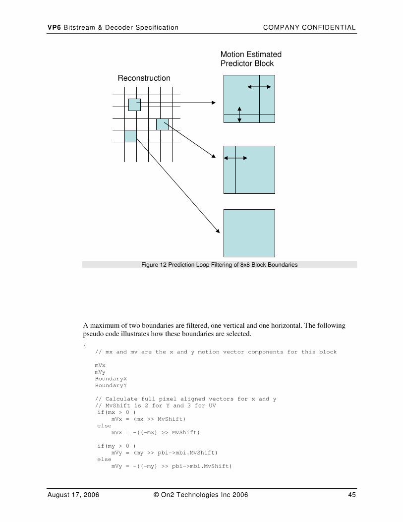
VP6 Bitstream & Decoder Specif ication COMPANY CONFIDENTIAL
August 17, 2006 © On2 Technologies Inc 2006 45
Figure 12 Prediction Loop Filtering of 8x8 Block Boundaries
A maximum of two boundaries are filtered, one vertical and one horizontal. The following
pseudo code illustrates how these boundaries are selected.
{
// mx and mv are the x and y motion vector components for this block
mVx
mVy
BoundaryX
BoundaryY
// Calculate full pixel aligned vectors for x and y
// MvShift is 2 for Y and 3 for UV
if(mx > 0 )
mVx = (mx >> MvShift)
else
mVx = -((-mx) >> MvShift)
if(my > 0 )
mVy = (my >> pbi->mbi.MvShift)
else
mVy = -((-my) >> pbi->mbi.MvShift)
Reconstruction
Motion Estimated Predictor Block
VP6 Bitstream & Decoder Specif ication COMPANY CONFIDENTIAL
August 17, 2006 © On2 Technologies Inc 2006 46
// calculate block border position for x
BoundaryX = (8 – (mVx & 7))&7
// calculate block border position for y
BoundaryY = (8 - (mVy & 7))&7
}
The values of BoundaryX and BoundaryY are the offsets in x and y of the edges that should
be filtered from the top left hand corner of the 8x8 region pointed to by the whole pixel
aligned vectors mVx and mVy.
Two filter options are defined:
� A deringing filter: has de-blocking & de-ringing characteristics (This option is not
currently supported by the decoder (see Table 3)
� A deblocking filter: has only de-blocking characteristic.
The deblocking loop filter comprises a 4-tap filter (1, -3, 3, -1) and a quantizer dependant
bounding function applied across the horizontal and vertical block boundaries as illustrated
by the following pseudo code. The limit values used by the bounding function are defined in
a table indexed by the current quantizer level (see DctQMask in Table 1).
// Quantizer level dependent limit values
PredictionLoopFilterLimitValues [64] =
{
30, 25, 20, 20, 15, 15, 14, 14,
13, 13, 12, 12, 11, 11, 10, 10,
9, 9, 8, 8, 7, 7, 7, 7,
6, 6, 6, 6, 5, 5, 5, 5,
4, 4, 4, 4, 3, 3, 3, 3,
2, 2, 2, 2, 2, 2, 2, 2,
2, 2, 2, 2, 2, 2, 2, 2,
1, 1, 1, 1, 1, 1, 1, 1
}
// Function to clamp values to the integer range 0 to 255
Clamp0To255( Input )
{
If ( Input < 0 )
Return 0
Else if ( Input > 255 )
Return 255
Else
Return Input
}
// Function to convert a signed value to an absolute value
abs ( SignedVal )
{
if ( SignedVal < 0 )
return –SignedVal
else
return SignedVal
}
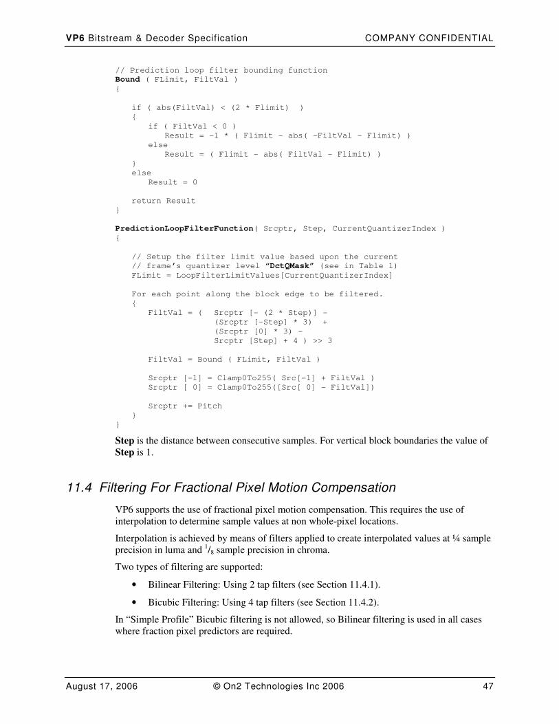
VP6 Bitstream & Decoder Specif ication COMPANY CONFIDENTIAL
August 17, 2006 © On2 Technologies Inc 2006 47
// Prediction loop filter bounding function
Bound ( FLimit, FiltVal )
{
if ( abs(FiltVal) < (2 * Flimit) )
{
if ( FiltVal < 0 )
Result = -1 * ( Flimit - abs( -FiltVal - Flimit) )
else
Result = ( Flimit - abs( FiltVal - Flimit) )
}
else
Result = 0
return Result
}
PredictionLoopFilterFunction( Srcptr, Step, CurrentQuantizerIndex )
{
// Setup the filter limit value based upon the current
// frame’s quantizer level “DctQMask” (see in Table 1)
FLimit = LoopFilterLimitValues[CurrentQuantizerIndex]
For each point along the block edge to be filtered.
{
FiltVal = ( Srcptr [- (2 * Step)] -
(Srcptr [-Step] * 3) +
(Srcptr [0] * 3) -
Srcptr [Step] + 4 ) >> 3
FiltVal = Bound ( FLimit, FiltVal )
Srcptr [-1] = Clamp0To255( Src[-1] + FiltVal )
Srcptr [ 0] = Clamp0To255([Src[ 0] - FiltVal])
Srcptr += Pitch
}
}
Step is the distance between consecutive samples. For vertical block boundaries the value of
Step is 1.
11.4 Filtering For Fractional Pixel Motion Compensation
VP6 supports the use of fractional pixel motion compensation. This requires the use of
interpolation to determine sample values at non whole-pixel locations.
Interpolation is achieved by means of filters applied to create interpolated values at ¼ sample
precision in luma and 1/8 sample precision in chroma.
Two types of filtering are supported:
• Bilinear Filtering: Using 2 tap filters (see Section 11.4.1).
• Bicubic Filtering: Using 4 tap filters (see Section 11.4.2).
In “Simple Profile” Bicubic filtering is not allowed, so Bilinear filtering is used in all cases
where fraction pixel predictors are required.
VP6 Bitstream & Decoder Specif ication COMPANY CONFIDENTIAL
August 17, 2006 © On2 Technologies Inc 2006 48
In Advanced Profile the decoder uses criteria specified by the encoder in the frame header
(see Table 2) to select at the block level between bicubic and bilinear filtering.
AutoSelectPMFlag . Where this flag is set to 0 the decoder must use Bilinear or bicubic
filtering exclusively as specified by the BiCubicOrBilinearFiltFlag. Where this flag is set to
1 the filter choice is defined by the prediction block variance and motion vector size.
PredictionFilterMvSizeThresh. This field specifies a motion vector size threshold. Where
the magnitude of either the x or the y component of a vector is greater than the threshold
value the decoder must use the Bilinear filtering method. The field value is converted to a
threshold in ¼ pixel units as follows.
// has a non zero threshold been specified
if ( PredictionFilterMvSizeThresh > 0 )
{
FilterMvSizeThresh = (1 << (FilterMvSizeThresh - 1)) << 2
}
// No motion vector length restriction
Else
FilterMvSizeThresh = ((MAX_MV_EXTENT >> 1) + 1) << 2
PredictionFilterVarThresh. This field is used to specify a prediction block variance
threshold that is used to select between bilinear and bicubic filtering. The threshold is only
tested in cases where bicubic filtering is allowed and the magnitude of both the x and the y
motion vector components is less than the size threshold specified above. A value of zero for
this field indicates that the decoder should not apply a variance threshold test and should use
the bicubic filtering method. In cases where this field is non-zero, bicubic filtering is used if
the measured variance of the prediction block is greater than a threshold number computed as
follows:-
FilterVarThresh = (PredictionFilterMvSizeThresh << 5)
The variance test is applied before filtering to create a fractional pixel prediction block, hence
the prediction block variance is calculated using an 8x8 whole sample aligned region of the
appropriate reconstruction buffer (either the previous frame or golden frame). The whole
sample aligned vectors used to define the top left hand corner of this region are calculated as
follows:-
// Mvshift is 2 for luma blocks and 3 for chroma blocks
WholeSampleAlignedX = (MvX >> MvShift)
WholeSampleAlignedY = (MvY >> MvShift)
For performance reasons the variance calculation does not consider all the points in the
prediction block. Rather it computes the variance based upon 16 sample points (every other
sample in every other row) as illustrated in the following pseudo code.
Var16Point ( DataPtr, Stride )
{
DiffPtr = DataPtr
XSum = 0
XXSum = 0
for ( i=0; i<4; i+=2 )
{
// Examine alternate pixel locations.
XSum += DiffPtr[0]
XXSum += DiffPtr[0] * DiffPtr[0]
XSum += DiffPtr[2]
XXSum += DiffPtr[2] * DiffPtr[2]
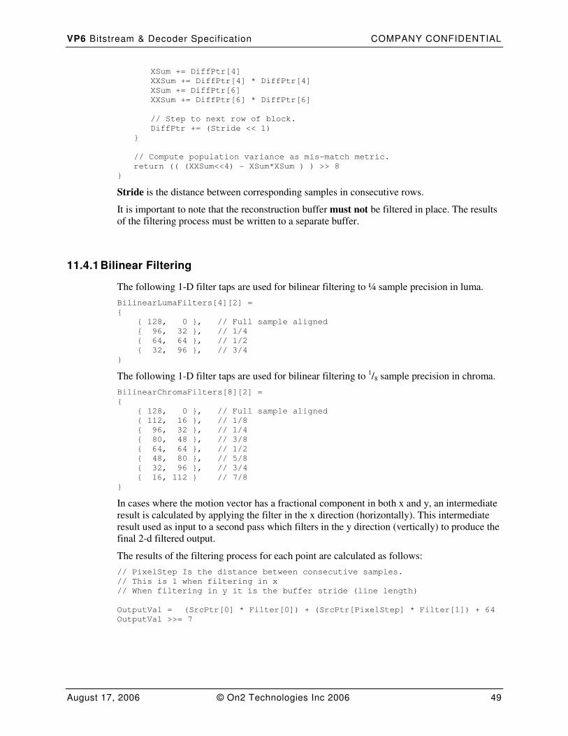
VP6 Bitstream & Decoder Specif ication COMPANY CONFIDENTIAL
August 17, 2006 © On2 Technologies Inc 2006 49
XSum += DiffPtr[4]
XXSum += DiffPtr[4] * DiffPtr[4]
XSum += DiffPtr[6]
XXSum += DiffPtr[6] * DiffPtr[6]
// Step to next row of block.
DiffPtr += (Stride << 1)
}
// Compute population variance as mis-match metric.
return (( (XXSum<<4) - XSum*XSum ) ) >> 8
}
Stride is the distance between corresponding samples in consecutive rows.
It is important to note that the reconstruction buffer must not be filtered in place. The results
of the filtering process must be written to a separate buffer.
11.4.1 Bilinear Filtering
The following 1-D filter taps are used for bilinear filtering to ¼ sample precision in luma.
BilinearLumaFilters[4][2] =
{
{ 128, 0 }, // Full sample aligned
{ 96, 32 }, // 1/4
{ 64, 64 }, // 1/2
{ 32, 96 }, // 3/4
}
The following 1-D filter taps are used for bilinear filtering to 1/8 sample precision in chroma.
BilinearChromaFilters[8][2] =
{
{ 128, 0 }, // Full sample aligned
{ 112, 16 }, // 1/8
{ 96, 32 }, // 1/4
{ 80, 48 }, // 3/8
{ 64, 64 }, // 1/2
{ 48, 80 }, // 5/8
{ 32, 96 }, // 3/4
{ 16, 112 } // 7/8
}
In cases where the motion vector has a fractional component in both x and y, an intermediate
result is calculated by applying the filter in the x direction (horizontally). This intermediate
result used as input to a second pass which filters in the y direction (vertically) to produce the
final 2-d filtered output.
The results of the filtering process for each point are calculated as follows:
// PixelStep Is the distance between consecutive samples.
// This is 1 when filtering in x
// When filtering in y it is the buffer stride (line length)
OutputVal = (SrcPtr[0] * Filter[0]) + (SrcPtr[PixelStep] * Filter[1]) + 64
OutputVal >>= 7
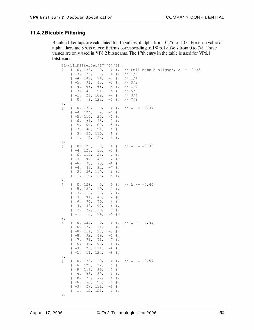
VP6 Bitstream & Decoder Specif ication COMPANY CONFIDENTIAL
August 17, 2006 © On2 Technologies Inc 2006 50
11.4.2 Bicubic Filtering
Bicubic filter taps are calculated for 16 values of alpha from -0.25 to -1.00. For each value of
alpha, there are 8 sets of coefficients corresponding to 1/8 pel offsets from 0 to 7/8. These
values are only used in VP6.2 bitstreams. The 17th entry in the table is used for VP6.1
bitstreams.
BicubicFilterSet[17][8][4] =
{ { 0, 128, 0, 0 }, // Full sample aligned, A ~= -0.25
{ -3, 122, 9, 0 }, // 1/8
{ -4, 109, 24, -1 }, // 1/4
{ -5, 91, 45, -3 }, // 3/8
{ -4, 68, 68, -4 }, // 1/2
{ -3, 45, 91, -5 }, // 5/8
{ -1, 24, 109, -4 }, // 3/4
{ 0, 9, 122, -3 }, // 7/8
},
{ { 0, 128, 0, 0 }, // A ~= -0.30
{ -4, 124, 9, -1 },
{ -5, 110, 25, -2 },
{ -6, 91, 46, -3 },
{ -5, 69, 69, -5 },
{ -3, 46, 91, -6 },
{ -2, 25, 110, -5 },
{ -1, 9, 124, -4 },
},
{ { 0, 128, 0, 0 }, // A ~= -0.35
{ -4, 123, 10, -1 },
{ -6, 110, 26, -2 },
{ -7, 92, 47, -4 },
{ -6, 70, 70, -6 },
{ -4, 47, 92, -7 },
{ -2, 26, 110, -6 },
{ -1, 10, 123, -4 },
},
{ { 0, 128, 0, 0 }, // A ~= -0.40
{ -5, 124, 10, -1 },
{ -7, 110, 27, -2 },
{ -7, 91, 48, -4 },
{ -6, 70, 70, -6 },
{ -4, 48, 92, -8 },
{ -2, 27, 110, -7 },
{ -1, 10, 124, -5 },
},
{ { 0, 128, 0, 0 }, // A ~= -0.45
{ -6, 124, 11, -1 },
{ -8, 111, 28, -3 },
{ -8, 92, 49, -5 },
{ -7, 71, 71, -7 },
{ -5, 49, 92, -8 },
{ -3, 28, 111, -8 },
{ -1, 11, 124, -6 },
},
{ { 0, 128, 0, 0 }, // A ~= -0.50
{ -6, 123, 12, -1 },
{ -9, 111, 29, -3 },
{ -9, 93, 50, -6 },
{ -8, 72, 72, -8 },
{ -6, 50, 93, -9 },
{ -3, 29, 111, -9 },
{ -1, 12, 123, -6 },
},
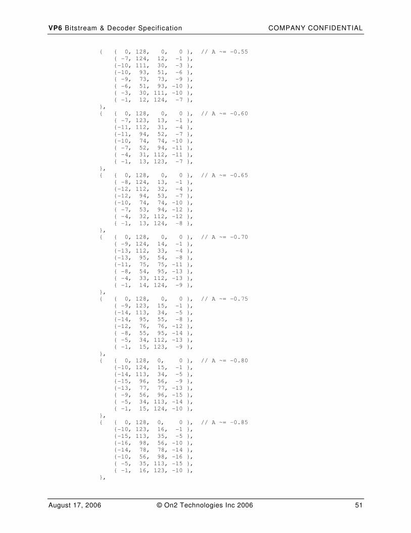
VP6 Bitstream & Decoder Specif ication COMPANY CONFIDENTIAL
August 17, 2006 © On2 Technologies Inc 2006 51
{ { 0, 128, 0, 0 }, // A ~= -0.55
{ -7, 124, 12, -1 },
{-10, 111, 30, -3 },
{-10, 93, 51, -6 },
{ -9, 73, 73, -9 },
{ -6, 51, 93, -10 },
{ -3, 30, 111, -10 },
{ -1, 12, 124, -7 },
},
{ { 0, 128, 0, 0 }, // A ~= -0.60
{ -7, 123, 13, -1 },
{-11, 112, 31, -4 },
{-11, 94, 52, -7 },
{-10, 74, 74, -10 },
{ -7, 52, 94, -11 },
{ -4, 31, 112, -11 },
{ -1, 13, 123, -7 },
},
{ { 0, 128, 0, 0 }, // A ~= -0.65
{ -8, 124, 13, -1 },
{-12, 112, 32, -4 },
{-12, 94, 53, -7 },
{-10, 74, 74, -10 },
{ -7, 53, 94, -12 },
{ -4, 32, 112, -12 },
{ -1, 13, 124, -8 },
},
{ { 0, 128, 0, 0 }, // A ~= -0.70
{ -9, 124, 14, -1 },
{-13, 112, 33, -4 },
{-13, 95, 54, -8 },
{-11, 75, 75, -11 },
{ -8, 54, 95, -13 },
{ -4, 33, 112, -13 },
{ -1, 14, 124, -9 },
},
{ { 0, 128, 0, 0 }, // A ~= -0.75
{ -9, 123, 15, -1 },
{-14, 113, 34, -5 },
{-14, 95, 55, -8 },
{-12, 76, 76, -12 },
{ -8, 55, 95, -14 },
{ -5, 34, 112, -13 },
{ -1, 15, 123, -9 },
},
{ { 0, 128, 0, 0 }, // A ~= -0.80
{-10, 124, 15, -1 },
{-14, 113, 34, -5 },
{-15, 96, 56, -9 },
{-13, 77, 77, -13 },
{ -9, 56, 96, -15 },
{ -5, 34, 113, -14 },
{ -1, 15, 124, -10 },
},
{ { 0, 128, 0, 0 }, // A ~= -0.85
{-10, 123, 16, -1 },
{-15, 113, 35, -5 },
{-16, 98, 56, -10 },
{-14, 78, 78, -14 },
{-10, 56, 98, -16 },
{ -5, 35, 113, -15 },
{ -1, 16, 123, -10 },
},
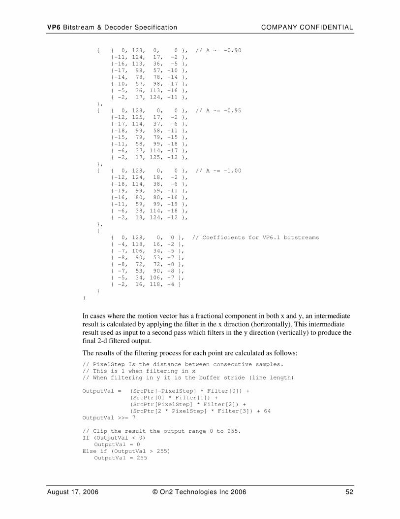
VP6 Bitstream & Decoder Specif ication COMPANY CONFIDENTIAL
August 17, 2006 © On2 Technologies Inc 2006 52
{ { 0, 128, 0, 0 }, // A ~= -0.90
{-11, 124, 17, -2 },
{-16, 113, 36, -5 },
{-17, 98, 57, -10 },
{-14, 78, 78, -14 },
{-10, 57, 98, -17 },
{ -5, 36, 113, -16 },
{ -2, 17, 124, -11 },
},
{ { 0, 128, 0, 0 }, // A ~= -0.95
{-12, 125, 17, -2 },
{-17, 114, 37, -6 },
{-18, 99, 58, -11 },
{-15, 79, 79, -15 },
{-11, 58, 99, -18 },
{ -6, 37, 114, -17 },
{ -2, 17, 125, -12 },
},
{ { 0, 128, 0, 0 }, // A ~= -1.00
{-12, 124, 18, -2 },
{-18, 114, 38, -6 },
{-19, 99, 59, -11 },
{-16, 80, 80, -16 },
{-11, 59, 99, -19 },
{ -6, 38, 114, -18 },
{ -2, 18, 124, -12 },
},
{
{ 0, 128, 0, 0 }, // Coefficients for VP6.1 bitstreams
{ -4, 118, 16, -2 },
{ -7, 106, 34, -5 },
{ -8, 90, 53, -7 },
{ -8, 72, 72, -8 },
{ -7, 53, 90, -8 },
{ -5, 34, 106, -7 },
{ -2, 16, 118, -4 }
}
}
In cases where the motion vector has a fractional component in both x and y, an intermediate
result is calculated by applying the filter in the x direction (horizontally). This intermediate
result used as input to a second pass which filters in the y direction (vertically) to produce the
final 2-d filtered output.
The results of the filtering process for each point are calculated as follows:
// PixelStep Is the distance between consecutive samples.
// This is 1 when filtering in x
// When filtering in y it is the buffer stride (line length)
OutputVal = (SrcPtr[-PixelStep] * Filter[0]) +
(SrcPtr[0] * Filter[1]) +
(SrcPtr[PixelStep] * Filter[2]) +
(SrcPtr[2 * PixelStep] * Filter[3]) + 64
OutputVal >>= 7
// Clip the result the output range 0 to 255.
If (OutputVal < 0)
OutputVal = 0
Else if (OutputVal > 255)
OutputVal = 255
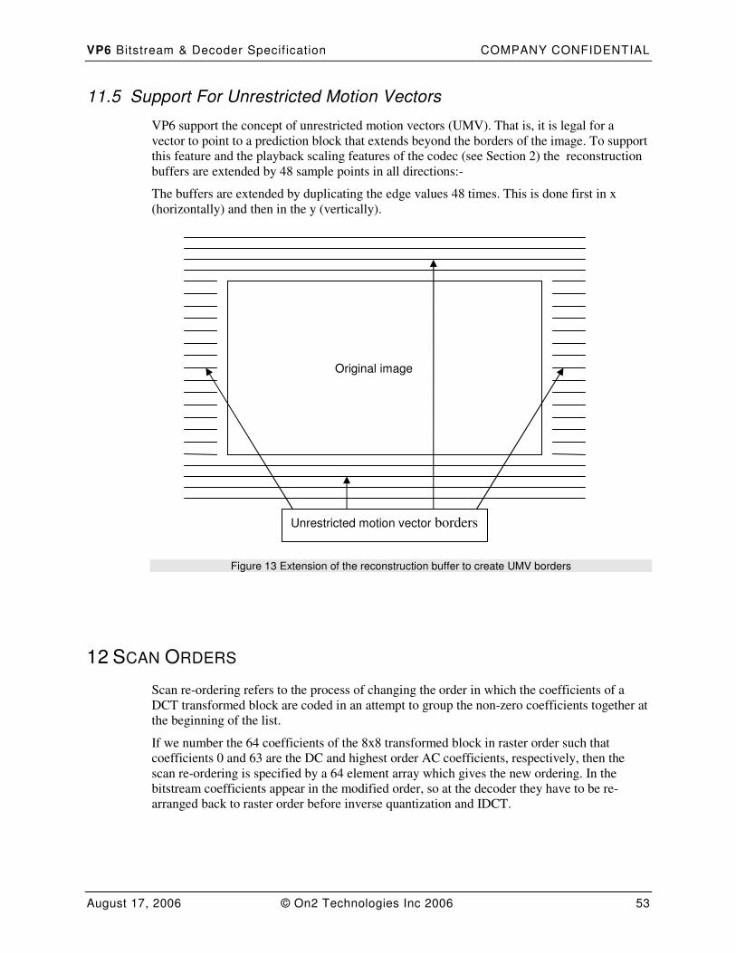
VP6 Bitstream & Decoder Specif ication COMPANY CONFIDENTIAL
August 17, 2006 © On2 Technologies Inc 2006 53
11.5 Support For Unrestricted Motion Vectors
VP6 support the concept of unrestricted motion vectors (UMV). That is, it is legal for a
vector to point to a prediction block that extends beyond the borders of the image. To support
this feature and the playback scaling features of the codec (see Section 2) the reconstruction
buffers are extended by 48 sample points in all directions:-
The buffers are extended by duplicating the edge values 48 times. This is done first in x
(horizontally) and then in the y (vertically).
Figure 13 Extension of the reconstruction buffer to create UMV borders
12 SCAN ORDERS
Scan re-ordering refers to the process of changing the order in which the coefficients of a
DCT transformed block are coded in an attempt to group the non-zero coefficients together at
the beginning of the list.
If we number the 64 coefficients of the 8x8 transformed block in raster order such that
coefficients 0 and 63 are the DC and highest order AC coefficients, respectively, then the
scan re-ordering is specified by a 64 element array which gives the new ordering. In the
bitstream coefficients appear in the modified order, so at the decoder they have to be re-
arranged back to raster order before inverse quantization and IDCT.
Original image
Unrestricted motion vector borders
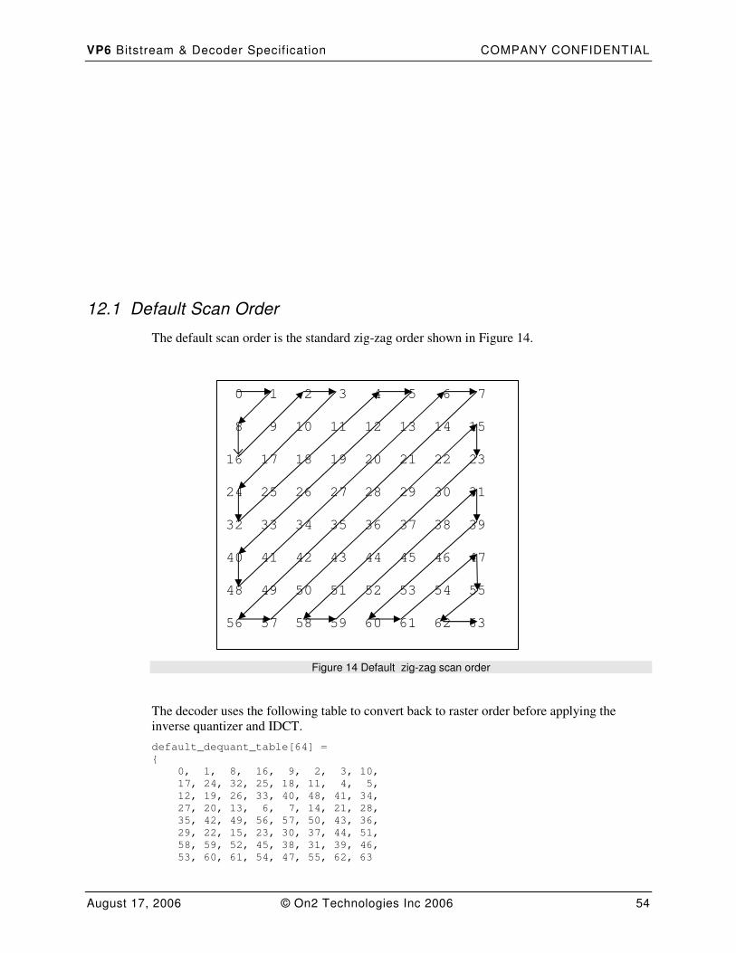
VP6 Bitstream & Decoder Specif ication COMPANY CONFIDENTIAL
August 17, 2006 © On2 Technologies Inc 2006 54
12.1 Default Scan Order
The default scan order is the standard zig-zag order shown in Figure 14.
Figure 14 Default zig-zag scan order
The decoder uses the following table to convert back to raster order before applying the
inverse quantizer and IDCT.
default_dequant_table[64] =
{
0, 1, 8, 16, 9, 2, 3, 10,
17, 24, 32, 25, 18, 11, 4, 5,
12, 19, 26, 33, 40, 48, 41, 34,
27, 20, 13, 6, 7, 14, 21, 28,
35, 42, 49, 56, 57, 50, 43, 36,
29, 22, 15, 23, 30, 37, 44, 51,
58, 59, 52, 45, 38, 31, 39, 46,
53, 60, 61, 54, 47, 55, 62, 63
0 1 2 3 4 5 6 7
8 9 10 11 12 13 14 15
16 17 18 19 20 21 22 23
24 25 26 27 28 29 30 31
32 33 34 35 36 37 38 39
40 41 42 43 44 45 46 47
48 49 50 51 52 53 54 55
56 57 58 59 60 61 62 63
VP6 Bitstream & Decoder Specif ication COMPANY CONFIDENTIAL
August 17, 2006 © On2 Technologies Inc 2006 55
}
12.2 Custom Scan Order
In addition to the default scan orders specified above VP6 supports the use of per frame
custom scan orders. The use of custom scan orders is an encoder decision and is signaled to
the decoder using the ScanOrderUpdateFlag (see Table 17).
If ScanOrderUpdateFlag indicates that there is no custom scan-order for a frame, the scan
order must be reset to the default.
For intra-coded frames the scan order is first set to the appropriate default. This default is
then updated using delta information encoded in the bitstream. For inter-coded frames deltas
are applied to the custom scan order used in the previous frame rather than to the one of the
default scan orders.
In all scan orders the first DCT coefficient is always the DC coefficient.
All references below to specific AC coefficients refer to their position in the standard zig-zag
scan order as shown in Figure 14. For example AC2 would refer to the second AC coefficient
in ziz-zag order that corresponds to coefficient 8 in the original raster order.
Custom scan order updates are read as part of the functional block “Coefficient Probability
Updates” (see Figure 2-Figure 5).
The 63 AC positions (numbered 1 to 63) in the modified scan order are split into 16 bands as
follows:
Band Number Positions
0 1
1 2 to 4
2 5 to 10
3 11 to 12
4 13 to 15
5 16 to 19
6 20 to 21
7 22 to 26
8 27 to 28
9 29 to 34
10 35 to 36
11 37 to 42
12 43 to 48
13 49 to 53
14 54 to 57
15 58 to 63
Table 16 Custom scan order bands
VP6 Bitstream & Decoder Specif ication COMPANY CONFIDENTIAL
August 17, 2006 © On2 Technologies Inc 2006 56
To specify a custom scan order, each AC coefficient (in zig zag order) is assigned to one of
the above bands. Within each band the coefficients are then sorted into ascending order based
upon the original zig-zag scan order.
For example, if AC7 and AC21 are labeled as belonging to band 3, then AC7 will be assigned
position 11 and AC21 position 12 in the modified scan order.
The following table describes the way custom scan order deltas are coded in the bitstream.
Field Type Notes
ScanOrderUpdateFlag b(1) Indicates whether scan-order update
follows.
63 Sets of:
CoeffBandUpdateFlag B(x) Flag indicating whether the
coefficient’s band has changed
NewCoeffBand b(4) The new band for the coefficient.
Table 17 Scan Order Update
ScanOrderUpdateFlag. Indicates whether or not a set of scan-order updates follow: (1) yes
(0) no.
CoeffBandUpdateFlag. A flag indicating whether or not a coefficient’s band has been
updated: (1) yes (0) no. Present only if ScanOrderUpdateFlag is 1.
NewCoeffBand. 4-bit band specifier for the coefficient. Present only if both
ScanOrderUpdateFlag and CoeffBandUpdateFlag are 1.
The following table gives the probabilities used for decoding CoeffBandUpdateFlag for
each of the AC coefficients in standard zig-zag order.
CoeffBandUpdateFlagProbs[64] =
{
NA, 132, 132, 159, 153, 151, 161, 170,
164, 162, 136, 110, 103, 114, 129, 118,
124, 125, 132, 136, 114, 110, 142, 135,
134, 123, 143, 126, 153, 183, 166, 161,
171, 180, 179, 164, 203, 218, 225, 217,
215, 206, 203, 217, 229, 241, 248, 243,
253, 255, 253, 255, 255, 255, 255, 255,
255, 255, 255, 255, 255, 255, 255, 255
}
The first entry in the table is a dummy entry for the DC coefficient. This always appears at
the start of the scan order and is never updated in the bitstream.
13 DCT COEFFICIENT TOKEN SET AND DECODING
Quantized DCT coefficients have a range of twelve bits plus sign (-2048, 2047) and are
represented by the following set of twelve tokens:
VP6 Bitstream & Decoder Specif ication COMPANY CONFIDENTIAL
August 17, 2006 © On2 Technologies Inc 2006 57
Index
Token Min Max #Extra Bits (incl. sign)
Arithmetic Encoding the Extra Bits
0 ZERO_TOKEN 0 0 *
1 ONE_TOKEN 1 1 1 B(128)
2 TWO_TOKEN 2 2 1 B(128)
3 THREE_TOKEN 3 3 1 B(128)
4 FOUR_TOKEN 4 4 1 B(128)
5 DCT_VAL_CATEGORY1 5 6 2 B(159), B(128)
6 DCT_VAL_CATEGORY2 7 10 3 B(165), B(145), B(128)
7 DCT_VAL_CATEGORY3 11 18 4 B(173), B(148), B(140), B(128)
8 DCT_VAL_CATEGORY4 19 34 5 B(176), B(155), B(140), B(135),
B(128)
9 DCT_VAL_CATEGORY5 35 66 6 B(180), B(157), B(141), B(134),
B(130), B(128)
10 DCT_VAL_CATEGORY6 67 2114 12 B(254), B(254), B(243), B(230),
B(196), B(177), B(153), B(140),
B(133), B(129), B(128)
11 DCT_EOB_TOKEN N/A N/A **
Table 18 Token Set and Extrabits
For each token the min-value represents the smallest value that can be encoded using that
token and the number of extra-bits reflects the range of values that the token can represent,
with the most significant bit of the magnitude sent first followed in turn by each subsequent
less significant bit. The last extrabit encoded is always the sign bit. In the arithmetic encoding
the extra bits are each encoded with differing probabilities as specified by the final column in
table 1. In Huffman encodings these bits are just pumped on to the bitstream.
For example, the token DCT_VAL_CATEGORY3 represents the eight numbers whose
magnitude is in the range (11,18) inclusive. This requires three bits for magnitude, plus one to
indicate sign giving a total of four extra-bits. The value –17 has the four extra-bits
represented by the Hex value 0xD (sign is LSB, magnitude coded as 17-11=6), so is encoded
by the token DCT_VAL_CATEGORY3 followed by the four bits 0xD.
In addition two tokens listed above are sometimes used to decode more than a single
coefficient. The table below describes these uses.
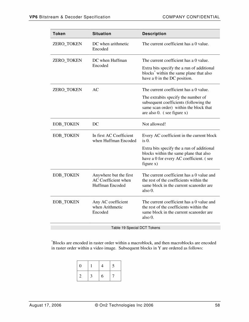
VP6 Bitstream & Decoder Specif ication COMPANY CONFIDENTIAL
August 17, 2006 © On2 Technologies Inc 2006 58
Token Situation Description
ZERO_TOKEN DC when arithmetic
Encoded
The current coefficient has a 0 value.
ZERO_TOKEN DC when Huffman
Encoded
The current coefficient has a 0 value.
Extra bits specify the a run of additional
blocks* within the same plane that also
have a 0 in the DC position.
ZERO_TOKEN AC The current coefficient has a 0 value.
The extrabits specify the number of
subsequent coefficients (following the
same scan order) within the block that
are also 0. ( see figure x)
EOB_TOKEN DC Not allowed!
EOB_TOKEN In first AC Coefficient
when Huffman Encoded
Every AC coefficient in the current block
is 0.
Extra bits specify the a run of additional
blocks within the same plane that also
have a 0 for every AC coefficient. ( see
figure x)
EOB_TOKEN Anywhere but the first
AC Coefficient when
Huffman Encoded
The current coefficient has a 0 value and
the rest of the coefficients within the
same block in the current scanorder are
also 0.
EOB_TOKEN Any AC coefficient
when Arithmetic
Encoded
The current coefficient has a 0 value and
the rest of the coefficients within the
same block in the current scanorder are
also 0.
Table 19 Special DCT Tokens
*Blocks are encoded in raster order within a macroblock, and then macroblocks are encoded
in raster order within a video image. Subsequent blocks in Y are ordered as follows:
0 1 4 5
2 3 6 7
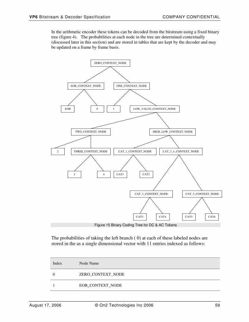
VP6 Bitstream & Decoder Specif ication COMPANY CONFIDENTIAL
August 17, 2006 © On2 Technologies Inc 2006 59
In the arithmetic encoder these tokens can be decoded from the bitstream using a fixed binary
tree (figure 4). The probabilities at each node in the tree are determined contextually
(discussed later in this section) and are stored in tables that are kept by the decoder and may
be updated on a frame by frame basis.
ZERO_CONTEXT_NODE
EOB_CONTEXT_NODE ONE_CONTEXT_NODE
LOW_VALUE_CONTEXT_NODE
HIGH_LOW_CONTEXT_NODE TWO_CONTEXT_NODE
THREE_CONTEXT_NODE CAT_3_4_CONTEXT_NODE
CAT_5_CONTEXT_NODE
CAT_1_CONTEXT_NODE
CAT_3_CONTEXT_NODE
EOB 0 1
2
3 4 CAT1 CAT2
CAT3 CAT4 CAT5 CAT6
Figure 15 Binary Coding Tree for DC & AC Tokens
The probabilities of taking the left branch ( 0) at each of these labeled nodes are
stored in the as a single dimensional vector with 11 entries indexed as follows:
Index Node Name
0 ZERO_CONTEXT_NODE
1 EOB_CONTEXT_NODE
VP6 Bitstream & Decoder Specif ication COMPANY CONFIDENTIAL
August 17, 2006 © On2 Technologies Inc 2006 60
2 ONE_CONTEXT_NODE
3 LOW_VAL_CONTEXT_NODE
4 TWO_CONTEXT_NODE
5 THREE_CONTEXT_NODE
6 HIGH_LOW_CONTEXT_NODE
7 CAT_ONE_CONTEXT_NODE
8 CAT_THREEFOUR_CONTEXT_NODE
9 CAT_THREE_CONTEXT_NODE
10 CAT_FIVE_CONTEXT_NODE
Table 20 DC & AC Coding Tree Node Probability Values
13.1 DCT Token Huffman Tree
In Figure 15 Binary Coding Tree for DC & AC Tokens a tree is specified for decoding DCT
coefficient tokens. This tree along with a set of probabilities which correspond to the
probabilities of taking the 0 branch at each node in the tree is converted to a set of Huffman
probabilities as follows:
Input: NodeProb[] : Set of 11 Node Probabilities.
Output: HuffProb[] : Set of 12 Huffman Probabilities.
DCTTokenBoolTreeToHuffProbs
{
HuffProb[DCT_EOB_TOKEN] = (NodeProb[0] * NodeProb[1] ) >> 8
HuffProb[ZERO_TOKEN] = (NodeProb[0] * (255 - NodeProb[1])) >> 8
Prob = 255 - NodeProb[0]
HuffProb[ONE_TOKEN] = (Prob * NodeProb[2]) >> 8
Prob = (Prob*(255 - NodeProb[2])) >> 8
Prob1 = (Prob * NodeProb[3]) >> 8
HuffProb[TWO_TOKEN] = (Prob1 * NodeProb[4]) >> 8
Prob1 = (Prob1 * (255 - NodeProb[4])) >> 8
HuffProb[THREE_TOKEN] = (Prob1 * NodeProb[5] ) >> 8
HuffProb[FOUR_TOKEN] = (Prob1 * (255 - NodeProb[5])) >> 8
Prob = (Prob * (255 - NodeProb[3])) >> 8
Prob1 = (Prob * NodeProb[6]) >> 8
HuffProb[DCT_VAL_CATEGORY1] = (Prob1 * NodeProb[7] ) >> 8
HuffProb[DCT_VAL_CATEGORY2] = (Prob1 * (255 - NodeProb[7])) >> 8
VP6 Bitstream & Decoder Specif ication COMPANY CONFIDENTIAL
August 17, 2006 © On2 Technologies Inc 2006 61
Prob = (Prob * (255 - NodeProb[6])) >> 8
Prob1 = (Prob * NodeProb[8]) >> 8
HuffProb[DCT_VAL_CATEGORY3] = (Prob1 * NodeProb[9] ) >> 8
HuffProb[DCT_VAL_CATEGORY4] = (Prob1 * (255 - NodeProb[9])) >> 8
Prob = (Prob * (255 - NodeProb[8])) >> 8
HuffProb[DCT_VAL_CATEGORY5] = (Prob * NodeProb[10] ) >> 8
HuffProb[DCT_VAL_CATEGORY6] = (Prob * (255 - NodeProb[10])) >> 8
}
13.2 DC Decoding
For Dc the decoder must maintain a 2 dimensional array of probabilities:
DCProbs[2][11]
The first dimension of this array is indexed by colour plane as follows:
Index Description
0 Y colour plane
1 U or V colour plane
Table 21 DC Node Contexts Dimension 1 Index
The second dimension of this array corresponds to one probability for each entry in Table:
DC & AC Coding Tree Node Probability Values.
At each key frame ( I frame) every probability value in this array of DC Probabilities is set to
128.
The DCProbs array persists from a keyframe (I Frame) to each subsequent interframe ( P
frame).
Updates to this Baseline set of probabilities are made on each frame, and are described in the
bitstream section described in Table 22 DC Coding Tree Plane Probability Updates.
Field
DC Coding Tree Node Updates for Y
DC Coding Tree Node Updates for UV
Table 22 DC Coding Tree Plane Probability Updates
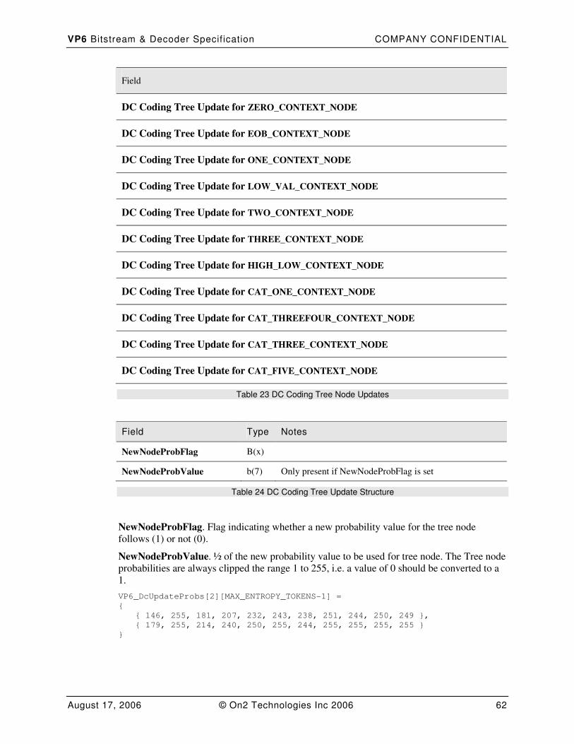
VP6 Bitstream & Decoder Specif ication COMPANY CONFIDENTIAL
August 17, 2006 © On2 Technologies Inc 2006 62
Field
DC Coding Tree Update for ZERO_CONTEXT_NODE
DC Coding Tree Update for EOB_CONTEXT_NODE
DC Coding Tree Update for ONE_CONTEXT_NODE
DC Coding Tree Update for LOW_VAL_CONTEXT_NODE
DC Coding Tree Update for TWO_CONTEXT_NODE
DC Coding Tree Update for THREE_CONTEXT_NODE
DC Coding Tree Update for HIGH_LOW_CONTEXT_NODE
DC Coding Tree Update for CAT_ONE_CONTEXT_NODE
DC Coding Tree Update for CAT_THREEFOUR_CONTEXT_NODE
DC Coding Tree Update for CAT_THREE_CONTEXT_NODE
DC Coding Tree Update for CAT_FIVE_CONTEXT_NODE
Table 23 DC Coding Tree Node Updates
Field Type Notes
NewNodeProbFlag B(x)
NewNodeProbValue b(7) Only present if NewNodeProbFlag is set
Table 24 DC Coding Tree Update Structure
NewNodeProbFlag. Flag indicating whether a new probability value for the tree node
follows (1) or not (0).
NewNodeProbValue. ½ of the new probability value to be used for tree node. The Tree node
probabilities are always clipped the range 1 to 255, i.e. a value of 0 should be converted to a
1.
VP6_DcUpdateProbs[2][MAX_ENTROPY_TOKENS-1] =
{
{ 146, 255, 181, 207, 232, 243, 238, 251, 244, 250, 249 },
{ 179, 255, 214, 240, 250, 255, 244, 255, 255, 255, 255 }
}
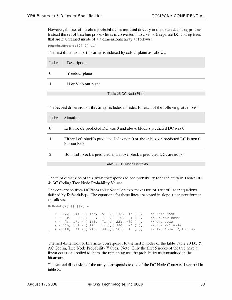
VP6 Bitstream & Decoder Specif ication COMPANY CONFIDENTIAL
August 17, 2006 © On2 Technologies Inc 2006 63
However, this set of baseline probabilities is not used directly in the token decoding process.
Instead the set of baseline probabilities is converted into a set of 6 separate DC coding trees
that are maintained inside of a 3 dimensional array as follows:
DcNodeContexts[2][3][11]
The first dimension of this array is indexed by colour plane as follows:
Index Description
0 Y colour plane
1 U or V colour plane
Table 25 DC Node Plane
The second dimension of this array includes an index for each of the following situations:
Index Situation
0 Left block’s predicted DC was 0 and above block’s predicted DC was 0
1 Either Left block’s predicted DC is non 0 or above block’s predicted DC is non 0
but not both
2 Both Left block’s predicted and above block’s predicted DCs are non 0
Table 26 DC Node Contexts
The third dimension of this array corresponds to one probability for each entry in Table: DC
& AC Coding Tree Node Probability Values.
The conversion from DCProbs to DcNodeContexts makes use of a set of linear equations
defined by DcNodeEqs. The equations for these lines are stored in slope + constant format
as follows:
DcNodeEqs[5][3][2] =
{
{ { 122, 133 },{ 133, 51 },{ 142, -16 } }, // Zero Node
{ { 0, 1 },{ 0, 1 },{ 0, 1 } }, // UNUSED DUMMY
{ { 78, 171 },{ 169, 71 },{ 221, -30 } }, // One Node
{ { 139, 117 },{ 214, 44 },{ 246, -3 } }, // Low Val Node
{ { 168, 79 },{ 210, 38 },{ 203, 17 } }, // Two Node (2,3 or 4)
}
The first dimension of this array corresponds to the first 5 nodes of the table Table 20 DC &
AC Coding Tree Node Probability Values. Note: Only the first 5 nodes of the tree have a
linear equation applied to them, the remaining use the probability as transmitted in the
bitstream.
The second dimension of the array corresponds to one of the DC Node Contexts described in
table X.
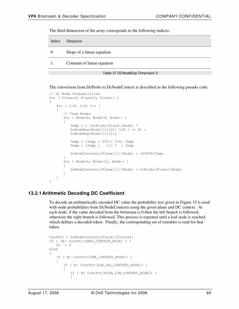
VP6 Bitstream & Decoder Specif ication COMPANY CONFIDENTIAL
August 17, 2006 © On2 Technologies Inc 2006 64
The third dimension of the array corresponds to the following indices:
Index Situation
0 Slope of a linear equation
1 Constant of linear equation
Table 27 DCNodeEqs Dimension 3
The conversion from DcProbs to DcNodeContext is described in the following pseudo code:
// DC Node Probabilities
for ( Plane=0; Plane<2; Plane++ )
{
for ( i=0; i<3; i++ )
{
// Tree Nodes
for ( Node=0; Node<5; Node++ )
{
Temp = ( (DcProbs[Plane][Node] *
DcNodeEqs[Node][i][0]+ 128 ) >> 8) +
DcNodeEqs[Node][i][1];
Temp = (Temp > 255)? 255: Temp
Temp = (Temp < 1)? 1 : Temp
DcNodeContexts[Plane][i][Node] = (UINT8)Temp
}
for ( Node=5; Node<11; Node++ )
{
DcNodeContexts[Plane][i][Node] = DcProbs[Plane][Node]
}
}
}
13.2.1 Arithmetic Decoding DC Coefficient
To decode an arithmetically encoded DC value the probability tree given in Figure 15 is used
with node probabilities from DcNodeContexts using the given plane and DC context. At
each node, if the value decoded from the bitstream is 0 then the left branch is followed,
otherwise the right branch is followed. This process is repeated until a leaf node is reached
which defines a decoded token. Finally, the corresponding set of extrabits is read for that
token.
ContPtr = DcNodeContexts[Plane][Context]
if ( !B( ContPtr[ZERO_CONTEXT_NODE] ) )
Dc = 0
else
{
if ( B( ContPtr[ONE_CONTEXT_NODE]) )
{
if ( B( ContPtr[LOW_VAL_CONTEXT_NODE]) )
{
if ( B( ContPtr[HIGH_LOW_CONTEXT_NODE]) )
{
VP6 Bitstream & Decoder Specif ication COMPANY CONFIDENTIAL
August 17, 2006 © On2 Technologies Inc 2006 65
if ( B( ContPtr[CAT_THREEFOUR_CONTEXT_NODE]) )
if( B( ContPtr[CAT_FIVE_CONTEXT_NODE])
token = DCT_VAL_CATEGORY6
else
token = DCT_VAL_CATEGORY5
else
if( B( ContPtr[CAT_THREE_CONTEXT_NODE]) )
token = DCT_VAL_CATEGORY4
else
token = DCT_VAL_CATEGORY3
}
else
{
if(B( ContPtr[CAT_ONE_CONTEXT_NODE])
token = DCT_VAL_CATEGORY2
else
token = DCT_VAL_CATEGORY1
}
value = TokenSetExtrabits[token].Min
BitsCount = TokenSetExtrabits[token].ExtraBits - 1
do
{
value += B(TokenSetExtrabits[token].Probs[BitsCount])
<<BitsCount)
BitsCount --
}
while( BitsCount >= 0)
SignBit = b(1)
Dc = ((value ^ -SignBit) + SignBit)
}
else
{
if ( B( ContPtr[TWO_CONTEXT_NODE]) )
{
if ( B( ContPtr[THREE_CONTEXT_NODE]))
token = FOUR_TOKEN
else
token = THREE_TOKEN
}
else
{
token = TWO_TOKEN
}
SignBit = b(1)
Dc = ((token ^ -SignBit) + SignBit)
}
}
else
{
SignBit = b(1)
Dc =((1 ^ -SignBit) + SignBit)
}
}
This code uses a nomenclature TokenSetExtrabits[row].Field which is a direct translation of
Table 18 Token Set and Extrabits. Field Probs refers to an array made from concatenating
the choices in field Arithmetic Encoding the Extra Bits, Min refers to the min field in the
table, and extra bits referes to the field marked # of extrabits.
Note : Decoding the dc requires that the contextual information regarding whether the blocks
immediately to the left of and above the current block have 0 or non 0 dc values.
VP6 Bitstream & Decoder Specif ication COMPANY CONFIDENTIAL
August 17, 2006 © On2 Technologies Inc 2006 66
The EOB token is explicitly forbidden from occurring in the DC position so there is no need
to encode the decision that differentiates between EOB and 0, the token may immediately be
assumed to be the ZERO_TOKEN.
13.2.2 Huffman Decoding DC Values
If Huffman coding of the DC tokens has been used then the function ConvertBoolTrees is
used to produce the Huffman decoding tree directly from the BoolCoder tree DCProb[2][20].
The result is stored as a set of probabilities for the dc in :
DcHuffProbs[2][12]
The first dimension of this array is indexed in the same way as Table 25 DC Node Plane.
The second dimension of this array is indexed by the token index as in Table 18 Token Set
and Extrabits.
These probabilities are then converted into a standard Huffman tree and are stored into the
array:
DcHuffTree[2]
The first dimension of this array is indexed in the same way as Table 25 DC Node Plane.
It should be noted that a 0 in the DC position when huffman encoded is accompanied by
extrabits that specify the number of additional blocks* within the same plane that also have a
0 in the DC position.
Pseudo Code for decoding DC in a given plane (Y or UV) follows:
if ( CurrentDcRunLen[Plane] > 0 )
{
-- CurrentDcRunLen[Plane]
}
else
{
token = DecodeBitsUsingHuffman(DcHuffTree[Plane])
value = TokenSetExtrabits[token].Min
if(token == ZERO_TOKEN)
{
Decode DC Zero Run as per 13.4 Decoding Huffman EOB and DC 0 Runs
CurrentDcRunLen[Plane] = DC Run Length
}
else
{
if(token <=FOUR_TOKEN)
{
SignBit = R(1)
}
else if(token <=DCT_VAL_CATEGORY5)
{
value += R(token-4)
SignBit = R(1)
}
else
{
value += R(11)
SignBit = R(1)
}
Dc = ((value ^ -SignBit) + SignBit)

VP6 Bitstream & Decoder Specif ication COMPANY CONFIDENTIAL
August 17, 2006 © On2 Technologies Inc 2006 67
}
}
13.3 AC Decoding
To decode ac coefficients the decoder must maintain a 4 dimensional set of probabilities:
AcProbs[2][3][6][11]
At each key frame ( I frame) every probability value in this array of AC Probabilities is set to
128. The ACProbs array persists from a keyframe (I Frame) to each subsequent interframe (P
frame).
The first dimension of the AcProbs is indexed by the plane that the block we are encoding is
in as follows:
Index Description
0 Y colour plane
1 U or V colour plane
Table 28 AC Prob Plane Index
The second Dimension of the AcProbs is indexed by the following context situations:
Index Situation
0 preceding decoded coefficient ( in current scan order) for the current block was 0
1 preceding decoded coefficient ( in current scan order) for the current block was 1
2 preceding decoded coefficient ( in current scan order) for the current block was
greater than 1
Table 29 AC Prob Prec Index
VP6 Bitstream & Decoder Specif ication COMPANY CONFIDENTIAL
August 17, 2006 © On2 Technologies Inc 2006 68
The third dimension of the AcProbs is indexed by the band that the coefficient is in as follows
Index Situation
0 Coefficient 1
1 Coefficients 2 – 4
2 Coefficients 5 – 10
3 Coefficients 11 – 21
4 Coefficients 22 – 36
5 Coefficients 37 – 63
Table 30 AC Prob Band Index
The fourth dimension of AcProbs is indexed by the context nodes as Table 20 DC & AC
Coding Tree Node Probability Values.
This entire table is updateable in the bitstream as follows:
Field
Ac Coding Tree Plane Updates for Preceding Case 0
Ac Coding Tree Plane Updates for Preceding Case 1
Ac Coding Tree Plane Updates for Preceding Case 2
Table 31 Plane AC Coding Tree Probability Updates
Field
AC Coding Tree Band Updates for Y
AC Coding Tree Band Updates for UV
Table 32 Plane AC Coding Tree Plane Probability Updates
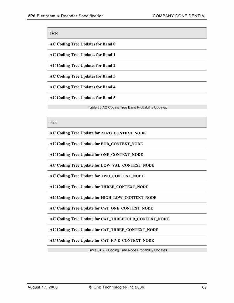
VP6 Bitstream & Decoder Specif ication COMPANY CONFIDENTIAL
August 17, 2006 © On2 Technologies Inc 2006 69
Field
AC Coding Tree Updates for Band 0
AC Coding Tree Updates for Band 1
AC Coding Tree Updates for Band 2
AC Coding Tree Updates for Band 3
AC Coding Tree Updates for Band 4
AC Coding Tree Updates for Band 5
Table 33 AC Coding Tree Band Probability Updates
Field
AC Coding Tree Update for ZERO_CONTEXT_NODE
AC Coding Tree Update for EOB_CONTEXT_NODE
AC Coding Tree Update for ONE_CONTEXT_NODE
AC Coding Tree Update for LOW_VAL_CONTEXT_NODE
AC Coding Tree Update for TWO_CONTEXT_NODE
AC Coding Tree Update for THREE_CONTEXT_NODE
AC Coding Tree Update for HIGH_LOW_CONTEXT_NODE
AC Coding Tree Update for CAT_ONE_CONTEXT_NODE
AC Coding Tree Update for CAT_THREEFOUR_CONTEXT_NODE
AC Coding Tree Update for CAT_THREE_CONTEXT_NODE
AC Coding Tree Update for CAT_FIVE_CONTEXT_NODE
Table 34 AC Coding Tree Node Probability Updates
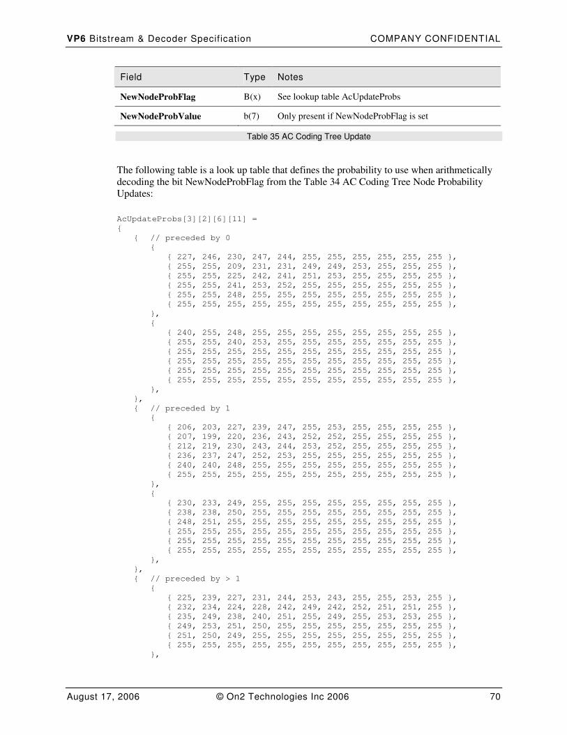
VP6 Bitstream & Decoder Specif ication COMPANY CONFIDENTIAL
August 17, 2006 © On2 Technologies Inc 2006 70
Field Type Notes
NewNodeProbFlag B(x) See lookup table AcUpdateProbs
NewNodeProbValue b(7) Only present if NewNodeProbFlag is set
Table 35 AC Coding Tree Update
The following table is a look up table that defines the probability to use when arithmetically
decoding the bit NewNodeProbFlag from the Table 34 AC Coding Tree Node Probability
Updates:
AcUpdateProbs[3][2][6][11] =
{
{ // preceded by 0
{
{ 227, 246, 230, 247, 244, 255, 255, 255, 255, 255, 255 },
{ 255, 255, 209, 231, 231, 249, 249, 253, 255, 255, 255 },
{ 255, 255, 225, 242, 241, 251, 253, 255, 255, 255, 255 },
{ 255, 255, 241, 253, 252, 255, 255, 255, 255, 255, 255 },
{ 255, 255, 248, 255, 255, 255, 255, 255, 255, 255, 255 },
{ 255, 255, 255, 255, 255, 255, 255, 255, 255, 255, 255 },
},
{
{ 240, 255, 248, 255, 255, 255, 255, 255, 255, 255, 255 },
{ 255, 255, 240, 253, 255, 255, 255, 255, 255, 255, 255 },
{ 255, 255, 255, 255, 255, 255, 255, 255, 255, 255, 255 },
{ 255, 255, 255, 255, 255, 255, 255, 255, 255, 255, 255 },
{ 255, 255, 255, 255, 255, 255, 255, 255, 255, 255, 255 },
{ 255, 255, 255, 255, 255, 255, 255, 255, 255, 255, 255 },
},
},
{ // preceded by 1
{
{ 206, 203, 227, 239, 247, 255, 253, 255, 255, 255, 255 },
{ 207, 199, 220, 236, 243, 252, 252, 255, 255, 255, 255 },
{ 212, 219, 230, 243, 244, 253, 252, 255, 255, 255, 255 },
{ 236, 237, 247, 252, 253, 255, 255, 255, 255, 255, 255 },
{ 240, 240, 248, 255, 255, 255, 255, 255, 255, 255, 255 },
{ 255, 255, 255, 255, 255, 255, 255, 255, 255, 255, 255 },
},
{
{ 230, 233, 249, 255, 255, 255, 255, 255, 255, 255, 255 },
{ 238, 238, 250, 255, 255, 255, 255, 255, 255, 255, 255 },
{ 248, 251, 255, 255, 255, 255, 255, 255, 255, 255, 255 },
{ 255, 255, 255, 255, 255, 255, 255, 255, 255, 255, 255 },
{ 255, 255, 255, 255, 255, 255, 255, 255, 255, 255, 255 },
{ 255, 255, 255, 255, 255, 255, 255, 255, 255, 255, 255 },
},
},
{ // preceded by > 1
{
{ 225, 239, 227, 231, 244, 253, 243, 255, 255, 253, 255 },
{ 232, 234, 224, 228, 242, 249, 242, 252, 251, 251, 255 },
{ 235, 249, 238, 240, 251, 255, 249, 255, 253, 253, 255 },
{ 249, 253, 251, 250, 255, 255, 255, 255, 255, 255, 255 },
{ 251, 250, 249, 255, 255, 255, 255, 255, 255, 255, 255 },
{ 255, 255, 255, 255, 255, 255, 255, 255, 255, 255, 255 },
},

VP6 Bitstream & Decoder Specif ication COMPANY CONFIDENTIAL
August 17, 2006 © On2 Technologies Inc 2006 71
{
{ 243, 244, 250, 250, 255, 255, 255, 255, 255, 255, 255 },
{ 249, 248, 250, 253, 255, 255, 255, 255, 255, 255, 255 },
{ 253, 255, 255, 255, 255, 255, 255, 255, 255, 255, 255 },
{ 255, 255, 255, 255, 255, 255, 255, 255, 255, 255, 255 },
{ 255, 255, 255, 255, 255, 255, 255, 255, 255, 255, 255 },
{ 255, 255, 255, 255, 255, 255, 255, 255, 255, 255, 255 },
},
},
}
The first dimension of this table is indexed by the values in Table 29 AC Prob Prec Index.
The second dimension is indexed by the Table 28 AC Prob Plane Index.
The third dimension is indexed by the Table 30 AC Prob Band Index.
The fourth dimension of this array corresponds to one probability for each entry in Table 20
DC & AC Coding Tree Node Probability Values.
13.3.1 Decoding Arithmetic Encoded AC Coefficients
Decoding AC requires all 4 pieces of contextual information listed above ; whether the
preceding coefficient in the block was 0, 1 or > 1, what plane the block is in, and the band of
the current coefficient. The set of probabilities that correspond to these 4 pieces of context
stored in ACProbs act as the binary decoding node probabilities for decoding an AC tokens
using the tree given in Figure 15.
At each node, if the value decoded from the bitstream is 0 then the left branch is followed,
otherwise the right branch is followed. This process is repeated until a leaf node is reached
which defines a decoded token. Finally, the corresponding set of extrabits is read for that
token.
Note: the decoded value of the DC coefficient is used as contextual information for the first
AC coefficient.
If a ZERO_TOKEN is encountered in AC it is followed by a run of zeros that is coded using
using the BoolCoder according to Section 7.3.
If the previously decoded AC token in the block was the ZERO_TOKEN then the next token
to be decoded can be neither ZERO_TOKEN nor EOB_TOKEN. In this case the first
decision in the tree is not required to be decoded, we can implicitly assume that the
ZERO_CONTEXT_NODE decision is a 1.
Following is pseudocode for decoding AC coefficients of a block using the arithmetic
encoder.
Set CoeffData to 64 0’s
if(dc == 0)
Prec = 0
Else if (dc == 1)
Prec = 1
Else
Prec = 2
EncodedCoeffs = 1
do
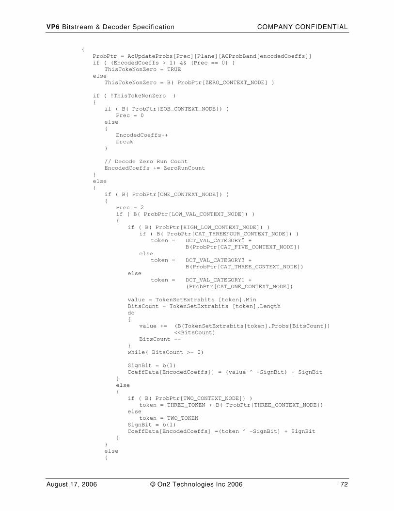
VP6 Bitstream & Decoder Specif ication COMPANY CONFIDENTIAL
August 17, 2006 © On2 Technologies Inc 2006 72
{
ProbPtr = AcUpdateProbs[Prec][Plane][ACProbBand[encodedCoeffs]]
if ( (EncodedCoeffs > 1) && (Prec == 0) )
ThisTokeNonZero = TRUE
else
ThisTokeNonZero = B( ProbPtr[ZERO_CONTEXT_NODE] )
if ( !ThisTokeNonZero )
{
if ( B( ProbPtr[EOB_CONTEXT_NODE]) )
Prec = 0
else
{
EncodedCoeffs++
break
}
// Decode Zero Run Count
EncodedCoeffs += ZeroRunCount
}
else
{
if ( B( ProbPtr[ONE_CONTEXT_NODE]) )
{
Prec = 2
if ( B( ProbPtr[LOW_VAL_CONTEXT_NODE]) )
{
if ( B( ProbPtr[HIGH_LOW_CONTEXT_NODE]) )
if ( B( ProbPtr[CAT_THREEFOUR_CONTEXT_NODE]) )
token = DCT_VAL_CATEGORY5 +
B(ProbPtr[CAT_FIVE_CONTEXT_NODE])
else
token = DCT_VAL_CATEGORY3 +
B(ProbPtr[CAT_THREE_CONTEXT_NODE])
else
token = DCT_VAL_CATEGORY1 +
(ProbPtr[CAT_ONE_CONTEXT_NODE])
value = TokenSetExtrabits [token].Min
BitsCount = TokenSetExtrabits [token].Length
do
{
value += (B(TokenSetExtrabits[token].Probs[BitsCount])
<<BitsCount)
BitsCount --
}
while( BitsCount >= 0)
SignBit = b(1)
CoeffData[EncodedCoeffs]] = (value ^ -SignBit) + SignBit
}
else
{
if ( B( ProbPtr[TWO_CONTEXT_NODE]) )
token = THREE_TOKEN + B( ProbPtr[THREE_CONTEXT_NODE])
else
token = TWO_TOKEN
SignBit = b(1)
CoeffData[EncodedCoeffs] =(token ^ -SignBit) + SignBit
}
}
else
{
VP6 Bitstream & Decoder Specif ication COMPANY CONFIDENTIAL
August 17, 2006 © On2 Technologies Inc 2006 73
Prec = 1
SignBit = b(1)
CoeffData[EncodedCoeffs] = (1 ^ -SignBit) + SignBit
}
EncodedCoeffs ++
}
} while (EncodedCoeffs < BLOCK_SIZE)
EncodedCoeffs --
Finished:
13.3.2 Decoding Huffman Encoded AC Coefficients
One complication for decoding Huffman coefficients is that if an EOB token is encountered
in ac coefficient 1 extra bits are used to specify the number of additional blocks within the
same plane that also have a 0 for every AC coefficient. ( see 13 DCT Coefficient Token Set)
Decoding Huffman encoded AC coefficients requires the use of 24 sepearate Huffman trees
stored in a 3 dimensional array:
AcHuffTree[2][3][4]
The first dimension of the AcProbs is indexed by the plane that the block we are encoding is
see Table 28 AC Prob Plane Index.
The second Dimension of the AcProbs is indexed by Table 29 AC Prob Prec Index
The third dimension of the AcProbs is indexed by the band that the coefficient is in as
follows:
Index Situation
0 Coefficient 1
1 Coefficients 2 – 4
2 Coefficients 5 – 10
3 Coefficients 11 – 63
Table 36 AC Huffman Prob Band Index
These trees are derived from the probabilities in AcProbs[2][3][0-3][11] the first 4 bands of
ACProbs using the as follows:
// AC
for ( Prec = 0; Prec < 3; Prec++ )
{
for ( Plane = 0; Plane < 2; Plane++ )
{

VP6 Bitstream & Decoder Specif ication COMPANY CONFIDENTIAL
August 17, 2006 © On2 Technologies Inc 2006 74
for ( Band = 0; Band < 4; Band++ )
{
BoolTreeToHuffCodes ( AcProbs[Plane][Prec][Band],
AcHuffProbs[Prec][Plane][Band] )
BuildHuffTree ( AcHuffTree[Prec][Plane][Band],
AcHuffProbs[Prec][Plane][Band], 12 )
}
}
}
Once these Huffman trees have been created, coefficients are decoded using the following
pseudo code:
Set CoeffData to 64 0’s
if(dc == 0)
Prec = 0
Else if (dc == 1)
Prec = 1
Else
Prec = 2
EncodedCoeffs = 1
if (CurrentAc1RunLen[Plane] > 0 )
{
-- CurrentAc1RunLen[Plane]
goto Finished
}
do
{
Band = VP6_CoeffToHuffBand[EncodedCoeffs]
token = DecodeBitsUsingHuffman (AcHuffTree[Prec][Plane][Band])
value = TokenSetExtrabits [token].Min
if(token == ZERO_TOKEN)
{
// Huffman Decode Zero Run Length
Prec =0
EncodedCoeffs += ZeroRun Length
continue
}
if(token == DCT_EOB_TOKEN)
{
if ( EncodedCoeffs == 1 )
{
// Decode DCT EOB Run as per 13.4
CurrentAc1RunLen[Plane] = EOB Token Run - 1
}
goto Finished;
}
if(token <=FOUR_TOKEN)
SignBit = R(1)
else if(token <=DCT_VAL_CATEGORY5)
{
value += R( (token-4))
SignBit = R(1)
}
else
{
value += R( 11)
SignBit = R(1)
}
CoeffData[EncodedCoeffs] = (value ^ -SignBit) + SignBit
Prec = (value>1)? 2 : 1
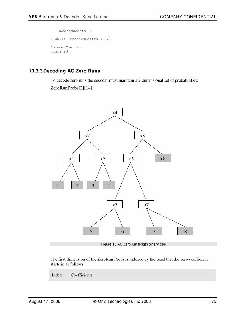
VP6 Bitstream & Decoder Specif ication COMPANY CONFIDENTIAL
August 17, 2006 © On2 Technologies Inc 2006 75
EncodedCoeffs ++
} while (EncodedCoeffs < 64)
EncodedCoeffs—-
Finished:
13.3.3 Decoding AC Zero Runs
To decode zero runs the decoder must maintain a 2 dimensional set of probabilities:
ZeroRunProbs[2][14].
Figure 16 AC Zero run length binary tree
The first dimension of the ZeroRun Probs is indexed by the band that the zero coefficient
starts in as follows
Index Coefficients
>4
>2 >8
>6 >8 >1 >3
>5 >7
5 6 7 8
1 2 3 4
VP6 Bitstream & Decoder Specif ication COMPANY CONFIDENTIAL
August 17, 2006 © On2 Technologies Inc 2006 76
0 Coefficients 1-5
1 Coefficients 6 – 63
Table 37 ZRL Band Index
The second dimension of the probability table is indexed by the node within Figure
16 AC Zero run length binary tree or the bit within the extrabits encoded if the run
length value is > 8 as follows:
Index Run Length
0 Probability of Run Length > 4
1 Probability of Run Length > 2
2 Probability of Run Length > 1
3 Probability of Run Length > 3
4 Probability of Run Length > 8
5 Probability of Run Length > 6
6 Probability of Run Length > 5
7 Probability of Run Length > 7
8 Probability of bit ( Run Length -9 ) & 1
9 Probability of bit (( Run Length – 9) >> 1 ) & 1
10 Probability of bit (( Run Length – 9) >> 2 ) & 1
11 Probability of bit (( Run Length – 9) >> 3 ) & 1
12 Probability of bit (( Run Length – 9) >> 4 ) & 1
13 Probability of bit (( Run Length – 9) >> 5 ) & 1
Table 38 ZRL Node Index
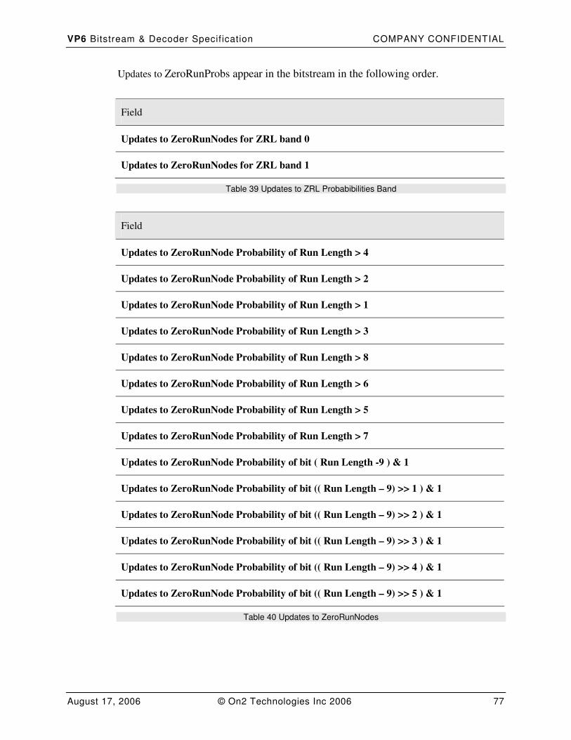
VP6 Bitstream & Decoder Specif ication COMPANY CONFIDENTIAL
August 17, 2006 © On2 Technologies Inc 2006 77
Updates to ZeroRunProbs appear in the bitstream in the following order.
Field
Updates to ZeroRunNodes for ZRL band 0
Updates to ZeroRunNodes for ZRL band 1
Table 39 Updates to ZRL Probabibilities Band
Field
Updates to ZeroRunNode Probability of Run Length > 4
Updates to ZeroRunNode Probability of Run Length > 2
Updates to ZeroRunNode Probability of Run Length > 1
Updates to ZeroRunNode Probability of Run Length > 3
Updates to ZeroRunNode Probability of Run Length > 8
Updates to ZeroRunNode Probability of Run Length > 6
Updates to ZeroRunNode Probability of Run Length > 5
Updates to ZeroRunNode Probability of Run Length > 7
Updates to ZeroRunNode Probability of bit ( Run Length -9 ) & 1
Updates to ZeroRunNode Probability of bit (( Run Length – 9) >> 1 ) & 1
Updates to ZeroRunNode Probability of bit (( Run Length – 9) >> 2 ) & 1
Updates to ZeroRunNode Probability of bit (( Run Length – 9) >> 3 ) & 1
Updates to ZeroRunNode Probability of bit (( Run Length – 9) >> 4 ) & 1
Updates to ZeroRunNode Probability of bit (( Run Length – 9) >> 5 ) & 1
Table 40 Updates to ZeroRunNodes
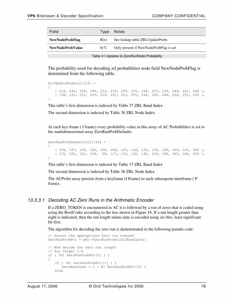
VP6 Bitstream & Decoder Specif ication COMPANY CONFIDENTIAL
August 17, 2006 © On2 Technologies Inc 2006 78
Field Type Notes
NewNodeProbFlag B(x) See lookup table ZRLUpdateProbs
NewNodeProbValue b(7) Only present if NewNodeProbFlag is set
Table 41 Updates to ZeroRunNode Probability
The probability used for decoding zrl probabilities node field NewNodeProbFlag is
determined from the following table.
ZrlUpdateProbs[2][14] =
{
{ 219, 246, 238, 249, 232, 239, 249, 255, 248, 253, 239, 244, 241, 248 },
{ 198, 232, 251, 253, 219, 241, 253, 255, 248, 249, 244, 238, 251, 255 },
}
This table’s first dimension is indexed by Table 37 ZRL Band Index
The second dimension is indexed by Table 38 ZRL Node Index.
At each key frame ( I frame) every probability value in this array of AC Probabilities is set to
the multidimensional array ZeroRunProbDefaults.
ZeroRunProbDefaults[2][14] =
{
{ 198, 197, 196, 146, 198, 204, 169, 142, 130, 136, 149, 149, 191, 249 },
{ 135, 201, 181, 154, 98, 117, 132, 126, 146, 169, 184, 240, 246, 254 },
}
This table’s first dimension is indexed by Table 37 ZRL Band Index
The second dimension is indexed by Table 38 ZRL Node Index
The ACProbs array persists from a keyframe (I Frame) to each subsequent interframe ( P
frame).
13.3.3.1 Decoding AC Zero Runs in the Arithmetic Encoder
If a ZERO_TOKEN is encountered in AC it is followed by a run of zeros that is coded using
using the BoolCoder according to the tree shown in Figure 16. If a run length greater than
eight is indicated, then the run length minus nine is encoded using six-bits, least significant
bit first.
The algorithm for decoding the zero run is demonstrated in the following pseudo code:
// Select the appropriate Zero run context
ZeroRunProbPtr = pbi->ZeroRunProbs[ZrlBand[pos]]
// Now decode the zero run length
// Run lenght 1-4
if ( !B( ZeroRunProbPtr[0] ) )
{
if ( !B( ZeroRunProbPtr[1] ) )
ZeroRunCount = 1 + B( ZeroRunProbPtr[2] )
else
VP6 Bitstream & Decoder Specif ication COMPANY CONFIDENTIAL
August 17, 2006 © On2 Technologies Inc 2006 79
ZeroRunCount = 3 + B( ZeroRunProbPtr[3] )
}
// Run length 5-8
else if ( !B( ZeroRunProbPtr[4] ) )
{
if ( !B( ZeroRunProbPtr[5] ) )
ZeroRunCount = 5 + B( ZeroRunProbPtr[6] )
else
ZeroRunCount = 7 + B( ZeroRunProbPtr[7] )
}
// Run length > 8
else
{
ZeroRunCount = B( ZeroRunProbPtr[8] )
ZeroRunCount += B( ZeroRunProbPtr[9] ) << 1
ZeroRunCount += B( ZeroRunProbPtr[10] ) << 2
ZeroRunCount += B( ZeroRunProbPtr[11] ) << 3
ZeroRunCount += B( ZeroRunProbPtr[12] ) << 4
ZeroRunCount += B( ZeroRunProbPtr[13] ) << 5
ZeroRunCount += 9
}
13.3.3.2 Decoding Huffman AC Zero Runs
To decode Huffman zero runs the decoder must maintain 2 zero run Huffman trees:
ZeroHuffTree[2].
The following tree is specified for decoding run lengths of zeros at DC position and EOB
tokens at the first AC position. This is converted to a set of Huffman probabilities as follows:
Input: NodeProb[] : Set of 8 Node Probabilities.
Output: HuffProb[] : Set of 9 Huffman Probabilities.
ZRLBoolTreeToHuffProbs
{
Prob = (NodeProb[0] * NodeProb[1]) >> 8
HuffProb[0] = (Prob * NodeProb[2]) >> 8
HuffProb[1] = (Prob * (255 - NodeProb[2])) >> 8
Prob = (NodeProb[0] * 255 - NodeProb[1])) >> 8
HuffProb[2] = (Prob * NodeProb[3]) >> 8
HuffProb[3] = (Prob * 255 - NodeProb[3])) >> 8
Prob = (255 - NodeProb[0]) * NodeProb[4]) >> 8
Prob = (Prob * NodeProb[5]) >> 8
HuffProb[4] = (Prob * NodeProb[6]) >> 8
HuffProb[5] = (Prob * 255 - NodeProb[6])) >> 8
Prob = ((255 - NodeProb[0]) * NodeProb[4]) >> 8
Prob = (Prob * (255 - NodeProb[5])) >> 8
HuffProb[6] = (Prob * NodeProb[7]) >> 8
HuffProb[7] = (Prob * (255 - NodeProb[7])) >> 8
Prob = ((255 - NodeProb[0]) * (255 - NodeProb[4])) >> 8
HuffProb[8] = Prob
}
VP6 Bitstream & Decoder Specif ication COMPANY CONFIDENTIAL
August 17, 2006 © On2 Technologies Inc 2006 80
These trees are converted from the trees ZeroRunProb in Section 13.3.3 Decoding AC
Zero Runs via the following pseudocode.
for ( i = 0; i < ZRL_BANDS; i++ )
{
ZRLBoolTreeToHuffCodes(ZeroRunProbs[i], ZeroHuffProbs[i] )
VP6_BuildHuffTree (ZeroHuffTree[i], ZeroHuffProbs[i])
}
These trees are then used to decode zero runs through generic Huffman decoding as is
demonstrated below:
// Read zero run-length
ZrlBand = ZrlBand[EncodedCoeffs]
ZrlToken = DecodeBitsUsingHuffman (ZeroHuffTree[ZrlBand])
if ( ZrlToken<8 )
EncodedCoeffs += ZrlToken
else
EncodedCoeffs += 8 + R(6)
13.4 Decoding Huffman EOB and DC 0 Runs
To decode Huffman EOB Runs use the Tree shown in Figure 17 Huffman EOB Run
Lengths and Huffman DC 0 Run Lengths.
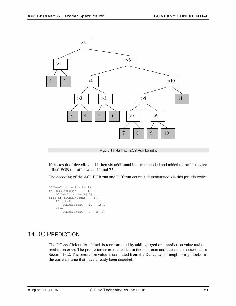
VP6 Bitstream & Decoder Specif ication COMPANY CONFIDENTIAL
August 17, 2006 © On2 Technologies Inc 2006 81
Figure 17 Huffman EOB Run Lengths
If the result of decoding is 11 then six additional bits are decoded and added to the 11 to give
a final EOB run of between 11 and 75.
The decoding of the AC1 EOB run and DC0 run count is demonstrated via this pseudo code:
EOBRunCount = 1 + R( 2)
if (EOBRunCount == 3 )
EOBRunCount += R( 2)
else if (EOBRunCount == 4 )
if ( R(1) )
EOBRunCount = 11 + R( 6)
else
EOBRunCount = 7 + R( 2)
14 DC PREDICTION
The DC coefficient for a block is reconstructed by adding together a prediction value and a
prediction error. The prediction error is encoded in the bitstream and decoded as described in
Section 13.2. The prediction value is computed from the DC values of neighboring blocks in
the current frame that have already been decoded.
>2
>6
2 1
>1
>5 >3
>4
3 4 5 6 >9 >7
>8
7 8 9 10
>10
11

VP6 Bitstream & Decoder Specif ication COMPANY CONFIDENTIAL
August 17, 2006 © On2 Technologies Inc 2006 82
For a particular block the DC values of up to two particular immediate neighbors contribute
to the prediction. The two blocks concerned are the blocks immediately to the left of and
immediately above the current block.
The DC value of a neighboring block only contributes to the prediction of the DC value for a
particular block if all of the following conditions are satisfied:
• The neighboring block exists; there is no left neighbor for blocks at the left edge and
no above neighbor for blocks at the top edge of the frame,
• The neighboring block was predicted from the same reference frame as the block
being predicted (last frame reconstruction or golden frame),
• Inter-coded blocks can only be predicted by neighboring inter-coded blocks and
intra-coded blocks can only be predicted by neighboring intra-coded blocks.
There are three scenarios:
• If both neighboring blocks are available the prediction is computed as the arithmetic
average of their DC values, truncated towards zero (values may be negative),
• If only one neighboring block is available, its DC value is used as the predictor,
• If neither neighboring block is available, the last decoded DC value for a block
predicted from the same reference frame is used as the predictor. At the beginning of
each frame this last decoded DC value is set to zero for each prediction frame type.
This is summarized in the following table:
Left
Available
Above
Available
Predictor
NO NO Last decoded DC value for a block with the same
prediction frame
NO YES A
YES NO L
YES YES (L + A + Sign(L+A) ) / 2
15 INVERSE QUANTIZATION
Each motion predicted 8x8 block (see Section 11) of a video frame is transformed by the
encoder to a set of 64 coefficients via the discrete cosine transform. These 64 coefficients are
then quantized by means of 2 separate uniform scalar quantizers : 1 for the DC coefficient,
and 1 for all 63 of the AC coefficients.
Reversing the uniform scalar quantizer involves performing integer multiplication on each of
its 64 coefficients. The quantization value (multiplicand) for DC is determined by indexing
the table DcQuantizationTable by the value DctQMask (from table Table 1). Likewise the
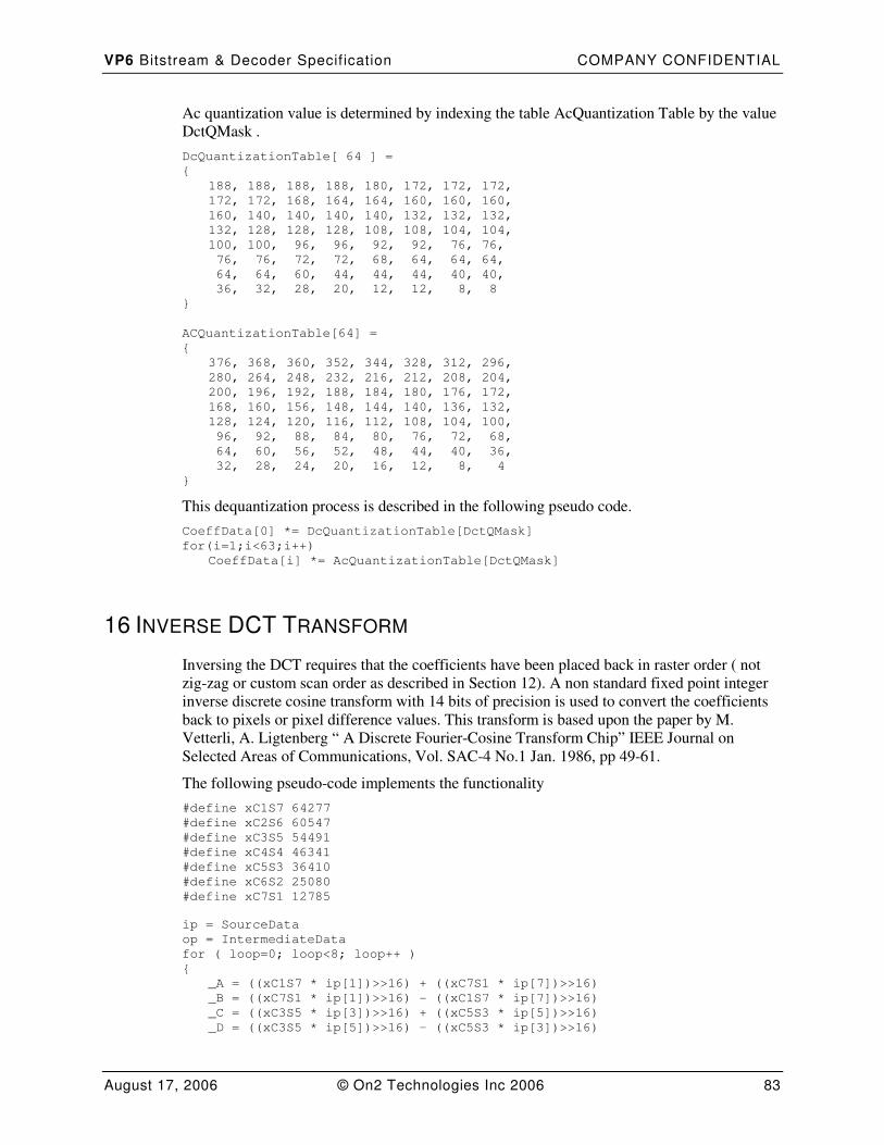
VP6 Bitstream & Decoder Specif ication COMPANY CONFIDENTIAL
August 17, 2006 © On2 Technologies Inc 2006 83
Ac quantization value is determined by indexing the table AcQuantization Table by the value
DctQMask .
DcQuantizationTable[ 64 ] =
{
188, 188, 188, 188, 180, 172, 172, 172,
172, 172, 168, 164, 164, 160, 160, 160,
160, 140, 140, 140, 140, 132, 132, 132,
132, 128, 128, 128, 108, 108, 104, 104,
100, 100, 96, 96, 92, 92, 76, 76,
76, 76, 72, 72, 68, 64, 64, 64,
64, 64, 60, 44, 44, 44, 40, 40,
36, 32, 28, 20, 12, 12, 8, 8 }
ACQuantizationTable[64] =
{
376, 368, 360, 352, 344, 328, 312, 296,
280, 264, 248, 232, 216, 212, 208, 204,
200, 196, 192, 188, 184, 180, 176, 172,
168, 160, 156, 148, 144, 140, 136, 132,
128, 124, 120, 116, 112, 108, 104, 100,
96, 92, 88, 84, 80, 76, 72, 68,
64, 60, 56, 52, 48, 44, 40, 36,
32, 28, 24, 20, 16, 12, 8, 4
}
This dequantization process is described in the following pseudo code.
CoeffData[0] *= DcQuantizationTable[DctQMask]
for(i=1;i<63;i++)
CoeffData[i] *= AcQuantizationTable[DctQMask]
16 INVERSE DCT TRANSFORM
Inversing the DCT requires that the coefficients have been placed back in raster order ( not
zig-zag or custom scan order as described in Section 12). A non standard fixed point integer
inverse discrete cosine transform with 14 bits of precision is used to convert the coefficients
back to pixels or pixel difference values. This transform is based upon the paper by M.
Vetterli, A. Ligtenberg “ A Discrete Fourier-Cosine Transform Chip” IEEE Journal on
Selected Areas of Communications, Vol. SAC-4 No.1 Jan. 1986, pp 49-61.
The following pseudo-code implements the functionality
#define xC1S7 64277
#define xC2S6 60547
#define xC3S5 54491
#define xC4S4 46341
#define xC5S3 36410
#define xC6S2 25080
#define xC7S1 12785
ip = SourceData
op = IntermediateData
for ( loop=0; loop<8; loop++ )
{
_A = ((xC1S7 * ip[1])>>16) + ((xC7S1 * ip[7])>>16)
_B = ((xC7S1 * ip[1])>>16) - ((xC1S7 * ip[7])>>16)
_C = ((xC3S5 * ip[3])>>16) + ((xC5S3 * ip[5])>>16)
_D = ((xC3S5 * ip[5])>>16) – ((xC5S3 * ip[3])>>16)
VP6 Bitstream & Decoder Specif ication COMPANY CONFIDENTIAL
August 17, 2006 © On2 Technologies Inc 2006 84
_Ad = ((xC4S4 * (_A - _C))>>16)
_Bd = ((xC4S4 * (_B - _D))>>16)
_Cd = _A + _C
_Dd = _B + _D
_E = ((xC4S4 * (ip[0] + ip[4]))>>16)
_F = ((xC4S4 * (ip[0] - ip[4]))>>16)
_G = ((xC2S6 * ip[2])>>16) + ((xC6S2 * ip[6])>>16)
_H = ((xC6S2 * ip[2])>>16) – ((xC2S6 * ip[6])>>16)
_Ed = _E - _G
_Gd = _E + _G
_Add = _F + _Ad
_Bdd = _Bd - _H
_Fd = _F - _Ad
_Hd = _Bd + _H
op[0] = _Gd + _Cd
op[7] = _Gd - _Cd
op[1] = _Add + _Hd
op[2] = _Add - _Hd
op[3] = _Ed + _Dd
op[4] = _Ed - _Dd
op[5] = _Fd + _Bdd
op[6] = _Fd - _Bdd
ip += 8
op+=8
}
VP6 Bitstream & Decoder Specif ication COMPANY CONFIDENTIAL
August 17, 2006 © On2 Technologies Inc 2006 85
ip = IntermediateData
op = OutputData
for ( loop=0; loop<8; loop++ )
{
_A = ((xC1S7 * ip[1*8])>>16) + ((xC7S1 * ip[7*8])>>16)
_B = ((xC7S1 * ip[1*8])>>16) - ((xC1S7 * ip[7*8])>>16)
_C = ((xC3S5 * ip[3*8])>>16) + ((xC5S3 * ip[5*8])>>16)
_D = ((xC3S5 * ip[5*8])>>16) – ((xC5S3 * ip[3*8])>>16)
_Ad = ((xC4S4 * (_A - _C))>>16)
_Bd = ((xC4S4 * (_B - _D)>>16)
_Cd = _A + _C
_Dd = _B + _D
_E = ((xC4S4 * (ip[0] + ip[4*8]))>>16)
_F = ((xC4S4 * (ip[0] - ip[4*8]))>>16)
_G = ((xC2S6 * ip[2*8])>>16) + ((xC6S2 * ip[6*8])>>16)
_H = ((xC6S2 * ip[2*8])>>16) – ((xC2S6 * ip[6*8])>>16)
_Ed = _E - _G
_Gd = _E + _G
_Add = _F + _Ad
_Bdd = _Bd - _H
_Fd = _F - _Ad
_Hd = _Bd + _H
op[0*8] = ((_Gd + _Cd ) >> 4)
op[7*8] = ((_Gd - _Cd ) >> 4)
op[1*8] = ((_Add + _Hd ) >> 4)
op[2*8] = ((_Add - _Hd ) >> 4)
op[3*8] = ((_Ed + _Dd ) >> 4)
op[4*8] = ((_Ed - _Dd ) >> 4)
op[5*8] = ((_Fd + _Bdd ) >> 4)
op[6*8] = ((_Fd - _Bdd ) >> 4)
ip++ // next column
op++
}
17 FRAME RECONSTRUCTION
Frame reconstruction is the process of re-building a reconstructed image by combining a
prediction signal and a prediction error signal.
In VP6 the following cases need to be considered.
• Reconstruction of Intra coded blocks (no prediction signal present).
• Reconstruction of Inter coded blocks which have a zero (0,0) motion vector.
• Reconstruction of Inter coded blocks that have a motion vector that is full pixel
aligned in both x and y.
• Reconstruction of Inter coded blocks the have a motion vector in one or both of x and
y that is not full pixel aligned
Note that this section deals only with the process of recombining the prediction signal and the
fully decoded prediction error signal. It does not consider DC prediction (see Section 14) as
this occurs before the IDCT.
VP6 Bitstream & Decoder Specif ication COMPANY CONFIDENTIAL
August 17, 2006 © On2 Technologies Inc 2006 86
17.1 Intra Coded Blocks
Intra coded frames and blocks are coded without any reference to any previous frame.
However, prior to encoding the value 128 is subtracted from all data samples, so this needs to
be added back in as part of the reconstruction process.
Intra block reconstruction can be summarized by the following pseudo code:
For each sample in the block
{
OutputValue = InputValue + 128
// Clip to the range 0-255
If ( OutputValue < 0 )
OutputValue = 0
Else If ( OutputValue > 255 )
OutputValue = 255
}
17.2 Zero Vectors
Zero motion vector prediction is a simplified case of motion compensation where each
sample is predicted by the sample at the same position in either the previous frame
reconstruction (mode CODE_INTER_NO_MV ) or the golden frame reconstruction (mode
CODE_USING_GOLDEN (See Section 10)).
No filtering is carried out on the prediction block and the reconstruction process can be
summarized by the following pseudo code:
For each sample in the block
{
OutputValue = PredictedValue + PrecitionError
// Clip to the range 0-255
If ( OutputValue < 0 )
OutputValue = 0
Else If ( OutputValue > 255 )
OutputValue = 255
}
17.3 Full Pixel Aligned Vectors
Reconstruction with a non-zero but full pixel aligned motion vectors involves combining the
prediction error signal with sample values from a set of points in either the previous or golden
frame reconstruction, that are offset by the given x and y from the samples that are being
reconstructed.
VP6 Bitstream & Decoder Specif ication COMPANY CONFIDENTIAL
August 17, 2006 © On2 Technologies Inc 2006 87
It is worth noting that a motion vector that is full pixel aligned for Y may be fractional
sample aligned for U and V, in which case the U and V blocks for the macro block will need
to be handled differently (see Section 17.4).
When using Advanced Profile and where the UseLoopFilter bit in the frame header is set to
1 (see Table 3), the issue is further complicated by prediction loop filtering (see Section
11.3). When the prediction loop filter is being used, the samples that will form the prediction
block are copied to and filtered in a temporary buffer and this temporary buffer is then used
as the source for prediction values. Prediction loop filtering MUST NOT update the
reconstruction buffer.
The process of reconstruction following on from any mandated prediction loop filtering can
be summarized by the following pseudo code:
For each sample in the block
{
OutputValue = PredictionValue + PrecitionError
// Clip to the range 0-255
If ( OutputValue < 0 )
OutputValue = 0
Else If ( OutputValue > 255 )
OutputValue = 255
}
17.4 Fractional Pixel Aligned Vectors
In order to reconstruct using a fractional pixel aligned vector it is necessary to filter a set of
sample points from either the previous frame or golden frame reconstruction buffer to
produce a new interpolated set of samples (see Section 11.4).
In Simple Profile the filtering is always Bilinear (see Section 11.4.1).
In Advanced profile the original full pixel aligned set of samples from which the fractional
points will be derived may first need to be filtered using the prediction loop filter to smooth
block discontinuities (see Section 11.3). The interpolation stage may use either a bilinear or a
bicubic filter (see Sections 11.4.1 and 11.4.2).
Having created a set of filtered, fractional pixel prediction points, the reconstruction then
proceeds as described below.
For each sample in the block
{
OutputValue = PredictionValue + PrecitionError
// Clip to the range 0-255
If ( OutputValue < 0 )
OutputValue = 0
Else If ( OutputValue > 255 )
OutputValue = 255
}
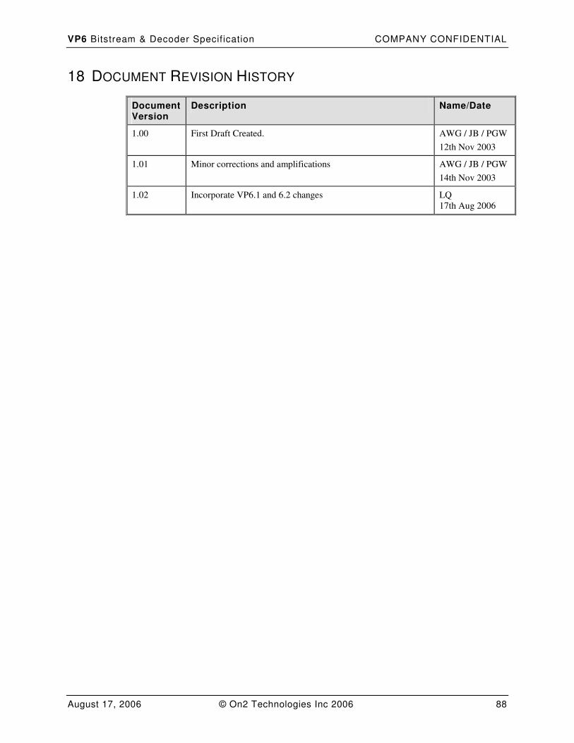
VP6 Bitstream & Decoder Specif ication COMPANY CONFIDENTIAL
August 17, 2006 © On2 Technologies Inc 2006 88
18 DOCUMENT REVISION HISTORY
Document Version
Description Name/Date
1.00 First Draft Created. AWG / JB / PGW
12th Nov 2003
1.01 Minor corrections and amplifications AWG / JB / PGW
14th Nov 2003
1.02 Incorporate VP6.1 and 6.2 changes LQ
17th Aug 2006