Embed Size (px)
Citation preview
VOYAGE DATA RECORDER
VR-5000
(Serial number 1001 or greater)
I
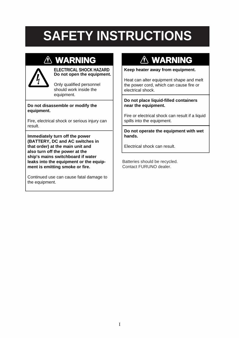
WARNINGELECTRICAL SHOCK HAZARDDo not open the equipment.
Only qualified personnelshould work inside theequipment.
Do not disassemble or modify theequipment.
Fire, electrical shock or serious injury canresult.
Immediately turn off the power (BATTERY, DC and AC switches inthat order) at the main unit and also turn off the power at the ship's mains switchboard if waterleaks into the equipment or the equip-ment is emitting smoke or fire.
Continued use can cause fatal damage tothe equipment.
WARNINGKeep heater away from equipment.
Heat can alter equipment shape and meltthe power cord, which can cause fire orelectrical shock.
Do not place liquid-filled containersnear the equipment.
Fire or electrical shock can result if a liquidspills into the equipment.
Do not operate the equipment with wethands.
Electrical shock can result.
SAFETY INSTRUCTIONS
Batteries should be recycled.Contact FURUNO dealer.
II
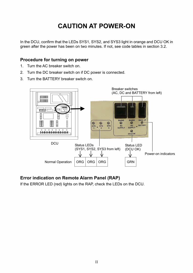
CAUTION AT POWER-ON
In the DCU, confirm that the LEDs SYS1, SYS2, and SYS3 light in orange and DCU OK in green after the power has been on two minutes. If not, see code tables in section 3.2.
Procedure for turning on power 1. Turn the AC breaker switch on.
2. Turn the DC breaker switch on if DC power is connected.
3. Turn the BATTERY breaker switch on.
Error indication on Remote Alarm Panel (RAP) If the ERROR LED (red) lights on the RAP, check the LEDs on the DCU.
Normal Operation ORG ORG ORG GRN
Breaker switches (AC, DC and BATTERY from left)
Status LEDs (SYS1, SYS2, SYS3 from left)
Power-on indicators
Status LED (DCU OK)
DCU
III
CONTENTS INTRODUCTION ................................................................................................................................... IV
SPECIFICATIONS..................................................................................................................................V
SYSTEM CONFIGURATION ..............................................................................................................VIII
Chapter 1 OPERATION ................................................................................................................... 1.1
1.1 OVERVIEW............................................................................................................................. 1.1
1.2 OPERATING PROCEDURE................................................................................................... 1.5
1.3 OPERATION ON REMOTE ALARM PANEL .......................................................................... 1.6
1.4 LED STATUS........................................................................................................................... 1.7
1.5 COPY OF VDR INFORMATION ............................................................................................. 1.7
1.6 HOW TO REMOVE DRU...................................................................................................... 1.8
Chapter 2 MAINTENANCE ............................................................................................................. 2.1
2.1 ROUTINE CHECK .................................................................................................................. 2.1
2.2 REPLACEMENT OF BATTERY.............................................................................................. 2.1
2.3 REPLACING ACOUSTIC BEACON ....................................................................................... 2.3
Chapter 3 TROUBLESHOOTING ................................................................................................... 3.1
3.1 GENERAL TROUBLE FINDING............................................................................................. 3.1
3.2 OPERATING STATUS ............................................................................................................ 3.2
Chapter 4 LOCATION OF PARTS .................................................................................................. 4.1
Chapter 5 SERIAL INTERFACE (IEC 61162-1).............................................................................. 5.1
Declaration of Conformity
IV
INTRODUCTION Word to the Owner
Thank you for purchasing this FURUNO Voyage Data Recorder. We are confident you will discover why FURUNO has become synonymous with quality and reliability.
What is a VDR?
The VR-5000 is a Voyage Data Recorder (VDR) which records various data and events encountered aboard ship. The purpose of the VDR is to help investigators locate the causes of marine incidents.
The revised SOLAS Chapter V requires the installation of VDR’s on passenger ships of 150 GT and above on all voyages and other ships of 3000 GT and above on international voyages and for newly built ships on and after 1 July, 2002.
Composition The basic VR-5000 consists of a Data Collection Unit (DCU), a Data Recording Unit (DRU) and microphones to record bridge audio. The DCU contains the Data Processor Unit, interface modules and backup batteries. It collects data from sensors as required by the IMO and IEC standards. The DCU processes the incoming data and information in the order of occurrence while old data is overwritten with new data for storage in the DRU for a 12 h period. The batteries supply power to the DCU to record bridge audio for 2 h in case of a main ship’s power failure.
The flash memory in the DRU stores the data coming from the DCU. All essential navigation and status data including bridge conversation, VHF communications, and radar images are recorded. The data can be retrieved by using playback software for investigation after an incident. The DRU components are embodied in the protective capsule. The capsule ensures survival and recovery of the recorded data after an incident. An acoustical pinger helps locate the DRU underwater.
FEATURES
• Reliable and fast data exchange between DCU and DRU via a single IEEE1394 cable.
• Easy commissioning and maintenance by PC downloading/uploading
• 12-hour recording of normal sensor loading in standard memory
• UTC time tagged for system synchronization and easy data retrieval
• Choice of flash memory capacity in the data recording unit
• Removable hard disk (HD) for storage and retrieval of data
• Meets IMO A.861 (20), IEC 61996 and other relevant standards.
V
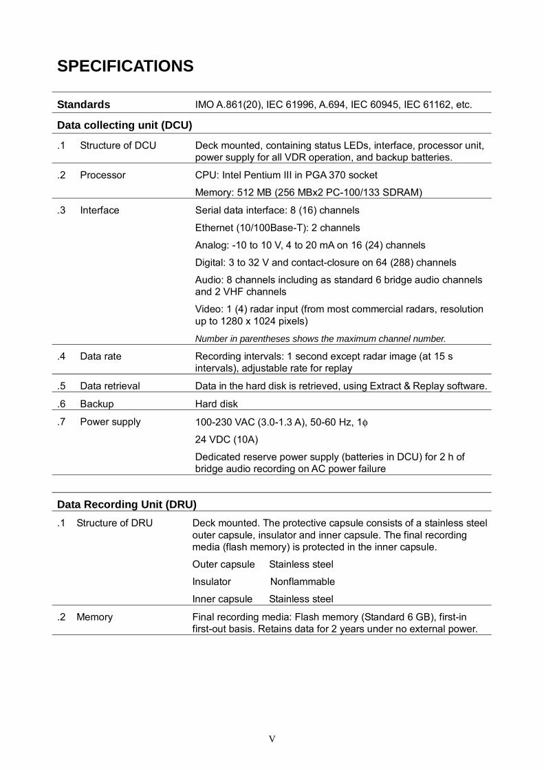
SPECIFICATIONS
Standards IMO A.861(20), IEC 61996, A.694, IEC 60945, IEC 61162, etc.
Data collecting unit (DCU)
.1 Structure of DCU Deck mounted, containing status LEDs, interface, processor unit, power supply for all VDR operation, and backup batteries.
.2 Processor CPU: Intel Pentium III in PGA 370 socket
Memory: 512 MB (256 MBx2 PC-100/133 SDRAM)
.3 Interface Serial data interface: 8 (16) channels
Ethernet (10/100Base-T): 2 channels
Analog: -10 to 10 V, 4 to 20 mA on 16 (24) channels
Digital: 3 to 32 V and contact-closure on 64 (288) channels
Audio: 8 channels including as standard 6 bridge audio channels and 2 VHF channels
Video: 1 (4) radar input (from most commercial radars, resolution up to 1280 x 1024 pixels)
Number in parentheses shows the maximum channel number.
.4 Data rate Recording intervals: 1 second except radar image (at 15 s intervals), adjustable rate for replay
.5 Data retrieval Data in the hard disk is retrieved, using Extract & Replay software.
.6 Backup Hard disk
.7 Power supply 100-230 VAC (3.0-1.3 A), 50-60 Hz, 1φ
24 VDC (10A)
Dedicated reserve power supply (batteries in DCU) for 2 h of bridge audio recording on AC power failure
Data Recording Unit (DRU) .1 Structure of DRU Deck mounted. The protective capsule consists of a stainless steel
outer capsule, insulator and inner capsule. The final recording media (flash memory) is protected in the inner capsule.
Outer capsule Stainless steel
Insulator Nonflammable
Inner capsule Stainless steel
.2 Memory Final recording media: Flash memory (Standard 6 GB), first-in first-out basis. Retains data for 2 years under no external power.
VI
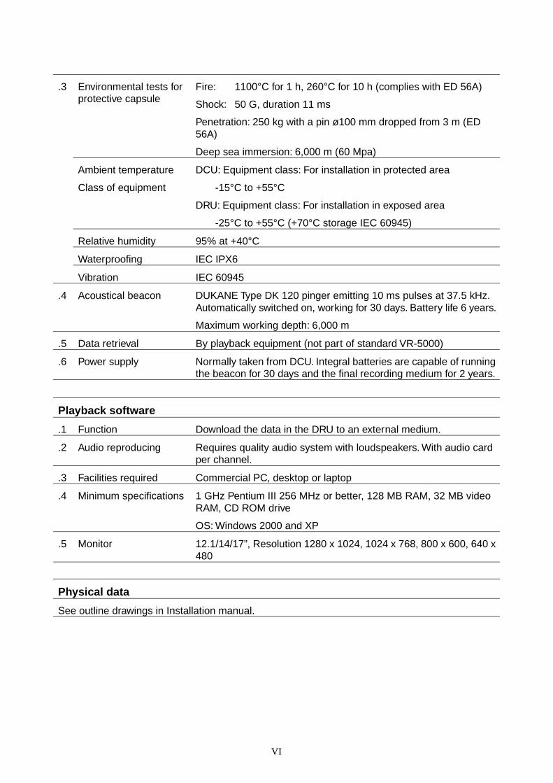
.3 Environmental tests for protective capsule
Fire: 1100°C for 1 h, 260°C for 10 h (complies with ED 56A)
Shock: 50 G, duration 11 ms
Penetration: 250 kg with a pin ø100 mm dropped from 3 m (ED 56A)
Deep sea immersion: 6,000 m (60 Mpa)
Ambient temperature
Class of equipment
DCU: Equipment class: For installation in protected area
-15°C to +55°C
DRU: Equipment class: For installation in exposed area
-25°C to +55°C (+70°C storage IEC 60945)
Relative humidity 95% at +40°C
Waterproofing IEC IPX6
Vibration IEC 60945
.4 Acoustical beacon DUKANE Type DK 120 pinger emitting 10 ms pulses at 37.5 kHz. Automatically switched on, working for 30 days. Battery life 6 years.
Maximum working depth: 6,000 m
.5 Data retrieval By playback equipment (not part of standard VR-5000)
.6 Power supply Normally taken from DCU. Integral batteries are capable of running the beacon for 30 days and the final recording medium for 2 years.
Playback software
.1 Function Download the data in the DRU to an external medium.
.2 Audio reproducing Requires quality audio system with loudspeakers. With audio card per channel.
.3 Facilities required Commercial PC, desktop or laptop
.4 Minimum specifications 1 GHz Pentium III 256 MHz or better, 128 MB RAM, 32 MB video RAM, CD ROM drive
OS: Windows 2000 and XP
.5 Monitor 12.1/14/17”, Resolution 1280 x 1024, 1024 x 768, 800 x 600, 640 x 480
Physical data
See outline drawings in Installation manual.
VII
MANUFACTURER’S DECLARATION Quality assurance
Furuno Electric Co., Ltd. Markets a wide range of industrial equipment and systems for aviation electronics, land survey and factory controls, and comprehensive range of marine electronic equipment and systems. Furuno is certified to ISO 9001 by Lloyd’s Register Quality Assurance Limited.
X-Radiation
None of this equipment gives rise to a dose rate >5 µJ/kgh (0,5 mrem/h) at 50 mm.
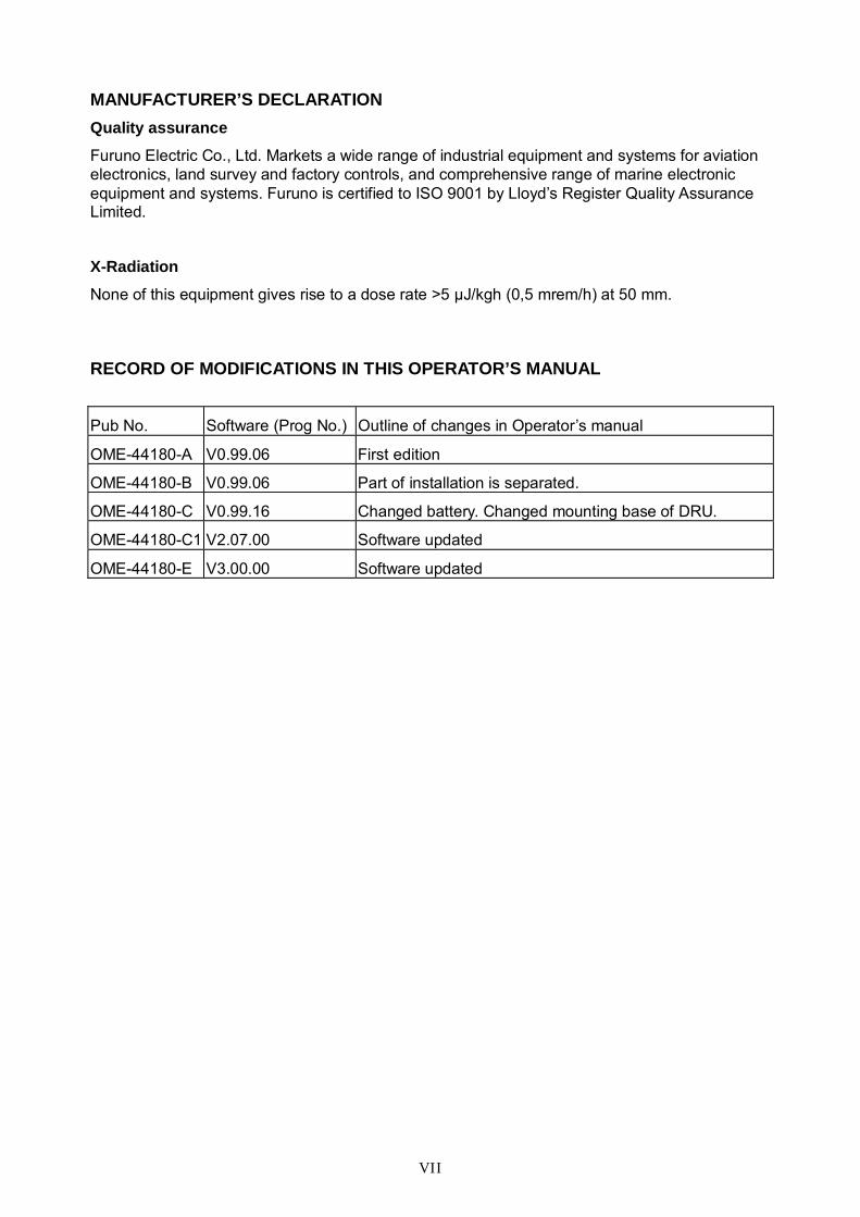
RECORD OF MODIFICATIONS IN THIS OPERATOR’S MANUAL
Pub No. Software (Prog No.) Outline of changes in Operator’s manual
OME-44180-A V0.99.06 First edition
OME-44180-B V0.99.06 Part of installation is separated.
OME-44180-C V0.99.16 Changed battery. Changed mounting base of DRU.
OME-44180-C1 V2.07.00 Software updated
OME-44180-E V3.00.00 Software updated
VIII
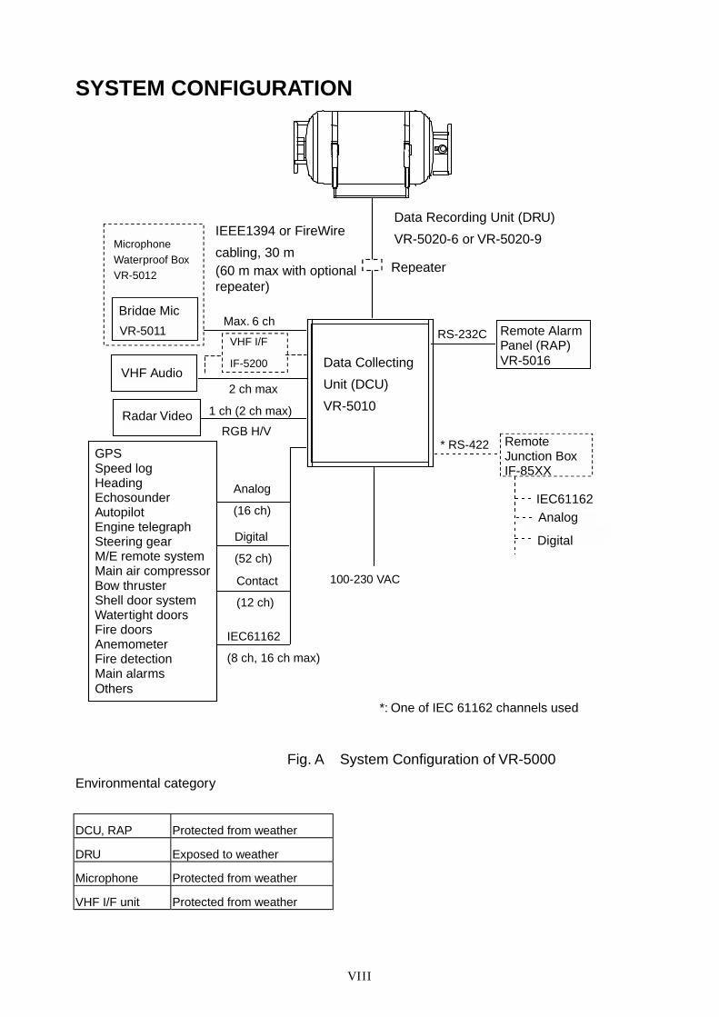
SYSTEM CONFIGURATION
100-230 VAC
Fig. A System Configuration of VR-5000
Environmental category
DCU, RAP Protected from weather
DRU Exposed to weather
Microphone Protected from weather
VHF I/F unit Protected from weather
IEEE1394 or FireWire
cabling, 30 m (60 m max with optional repeater)
Repeater
Data Recording Unit (DRU)
VR-5020-6 or VR-5020-9
GPS Speed log Heading Echosounder Autopilot Engine telegraph Steering gear M/E remote system Main air compressor Bow thruster Shell door system Watertight doors Fire doors Anemometer Fire detection Main alarms Others
Data Collecting
Unit (DCU)
VR-5010
Analog
(16 ch)
Digital
(52 ch)
Contact
(12 ch)
IEC61162
(8 ch, 16 ch max)
*: One of IEC 61162 channels used
Max. 6 ch
2 ch max
RGB H/V
1 ch (2 ch max)
RS-232C
* RS-422
Bridge Mic
VHF Audio
Radar Video
Remote Alarm Panel (RAP) VR-5016
Remote Junction Box IF-85XX
IEC61162 Analog
Digital
VHF I/F
IF-5200
VR-5011
Microphone Waterproof Box VR-5012
-1.1-
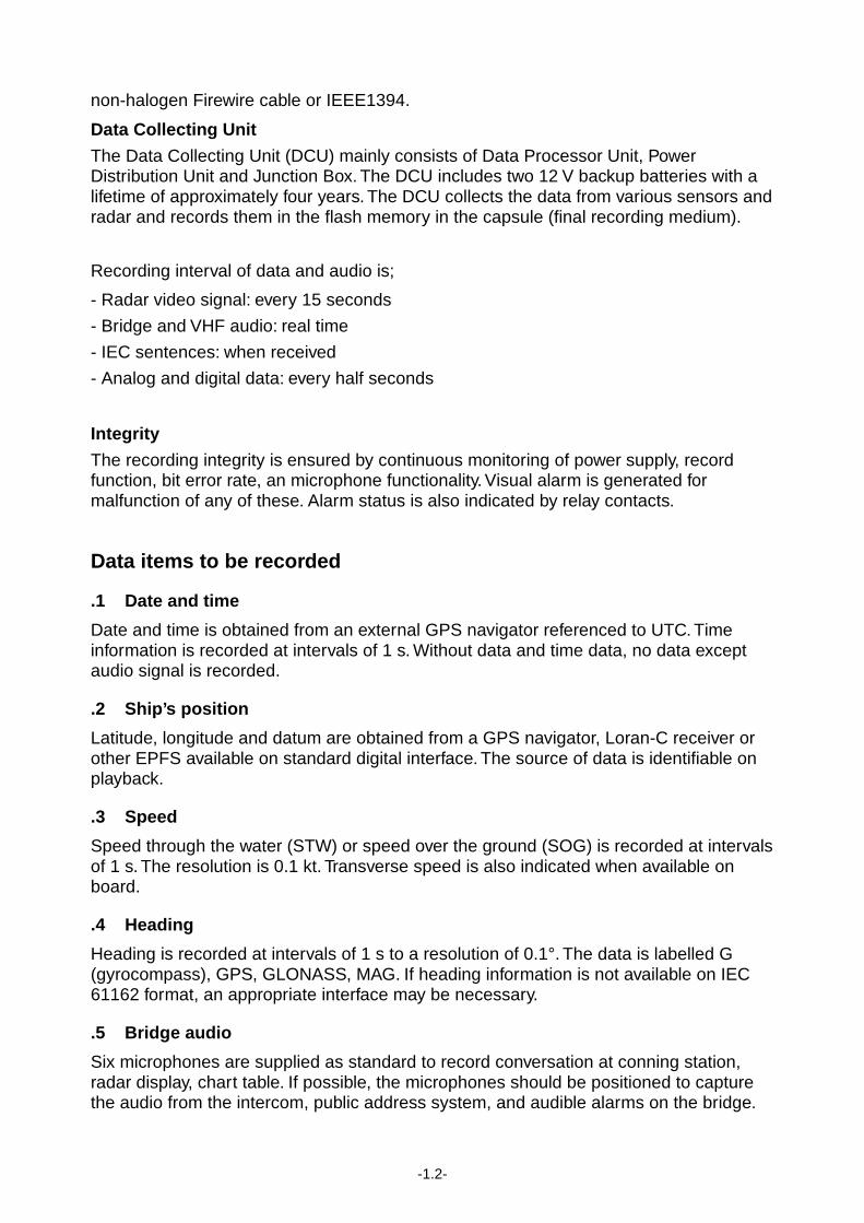
Chapter 1 OPERATION 1.1 OVERVIEW The VR-5000 consists of Data Collecting Unit or DCU, Data Recording Unit or DRU, and bridge microphone units. The VDR system continuously store data from the past 12 hours onto the Flash Memory in the capsule, erasing the oldest data stored as new data is recorded. The data to be recorded includes;
Parameters to be recorded IEC 61162 formatter Notes
.1 Date and time ZDA or RMC
.2 Own ship position GNS, DTM
.3 Speed VBW
.4 Heading HDT
.5 Bridge audio
.6 VHF communication audio
.7 Radar images RGB H/V
.8 Echosounder DPT
.9 IMO mandatory alarms ALR
.10 Rudder order and response RSA, HTM
.11 Engine order and response RPM, XDR
.12 Hull (door) openings status XDR
.13 Watertight and fire doors status XDR
.14 Acceleration and hull stress if available XDR, ALR
.15 Wind speed and direction if available MWV
Power Supply precaution
If ship’s mains power source (100-230 VAC) and emergency source fail, the VR-5000 continues to record bridge audio for 2 h from backup batteries.
Continuity of storing data
The VR-5000 should be provided with power to store data for 12 h on first-in, first-out basis. Recording is only terminated with a key under the following circumstances:
a) During essential maintenance while the vessel is in port.
b) When the vessel is laid-up.
c) In case of emergency, when the HD is removed.
Data Recording Unit
The Data Recording Unit is housed in a highly visible protective capsule which can withstand a fire of 1100°C for 1 hour and deep-sea pressure of 6000 m.
The underwater acoustic beacon (pinger) on the capsule automatically transmits 10 ms pulses at 37.5 kHz for at least 30 days when it is submerged in water. The expected life of the beacon is 6 years. The DRU is connected to the Data Collecting Unit (DCU) with a
-1.2-
non-halogen Firewire cable or IEEE1394.
Data Collecting Unit
The Data Collecting Unit (DCU) mainly consists of Data Processor Unit, Power Distribution Unit and Junction Box. The DCU includes two 12 V backup batteries with a lifetime of approximately four years. The DCU collects the data from various sensors and radar and records them in the flash memory in the capsule (final recording medium).
Recording interval of data and audio is;
- Radar video signal: every 15 seconds
- Bridge and VHF audio: real time
- IEC sentences: when received
- Analog and digital data: every half seconds
Integrity
The recording integrity is ensured by continuous monitoring of power supply, record function, bit error rate, an microphone functionality. Visual alarm is generated for malfunction of any of these. Alarm status is also indicated by relay contacts.
Data items to be recorded
.1 Date and time
Date and time is obtained from an external GPS navigator referenced to UTC. Time information is recorded at intervals of 1 s. Without data and time data, no data except audio signal is recorded.
.2 Ship’s position
Latitude, longitude and datum are obtained from a GPS navigator, Loran-C receiver or other EPFS available on standard digital interface. The source of data is identifiable on playback.
.3 Speed
Speed through the water (STW) or speed over the ground (SOG) is recorded at intervals of 1 s. The resolution is 0.1 kt. Transverse speed is also indicated when available on board.
.4 Heading
Heading is recorded at intervals of 1 s to a resolution of 0.1°. The data is labelled G (gyrocompass), GPS, GLONASS, MAG. If heading information is not available on IEC 61162 format, an appropriate interface may be necessary.
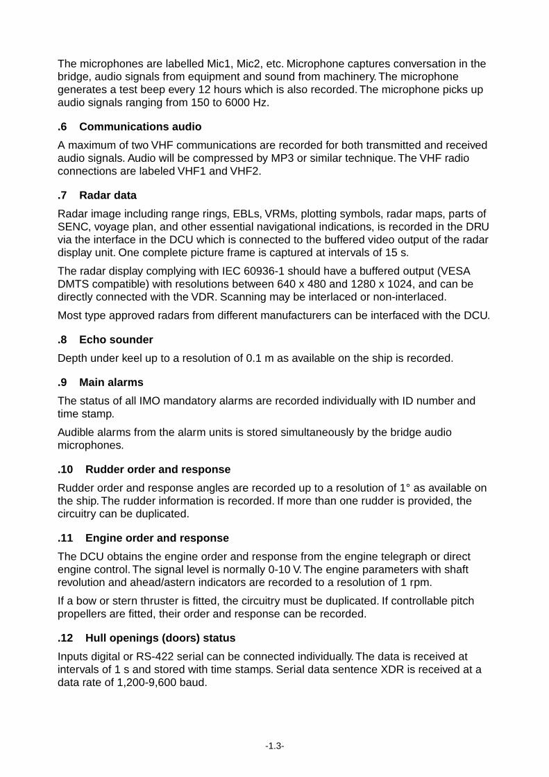
.5 Bridge audio
Six microphones are supplied as standard to record conversation at conning station, radar display, chart table. If possible, the microphones should be positioned to capture the audio from the intercom, public address system, and audible alarms on the bridge.
-1.3-
The microphones are labelled Mic1, Mic2, etc. Microphone captures conversation in the bridge, audio signals from equipment and sound from machinery. The microphone generates a test beep every 12 hours which is also recorded. The microphone picks up audio signals ranging from 150 to 6000 Hz.
.6 Communications audio
A maximum of two VHF communications are recorded for both transmitted and received audio signals. Audio will be compressed by MP3 or similar technique. The VHF radio connections are labeled VHF1 and VHF2.
.7 Radar data
Radar image including range rings, EBLs, VRMs, plotting symbols, radar maps, parts of SENC, voyage plan, and other essential navigational indications, is recorded in the DRU via the interface in the DCU which is connected to the buffered video output of the radar display unit. One complete picture frame is captured at intervals of 15 s.
The radar display complying with IEC 60936-1 should have a buffered output (VESA DMTS compatible) with resolutions between 640 x 480 and 1280 x 1024, and can be directly connected with the VDR. Scanning may be interlaced or non-interlaced.
Most type approved radars from different manufacturers can be interfaced with the DCU.
.8 Echo sounder
Depth under keel up to a resolution of 0.1 m as available on the ship is recorded.
.9 Main alarms
The status of all IMO mandatory alarms are recorded individually with ID number and time stamp.
Audible alarms from the alarm units is stored simultaneously by the bridge audio microphones.
.10 Rudder order and response
Rudder order and response angles are recorded up to a resolution of 1° as available on the ship. The rudder information is recorded. If more than one rudder is provided, the circuitry can be duplicated.
.11 Engine order and response
The DCU obtains the engine order and response from the engine telegraph or direct engine control. The signal level is normally 0-10 V. The engine parameters with shaft revolution and ahead/astern indicators are recorded to a resolution of 1 rpm.
If a bow or stern thruster is fitted, the circuitry must be duplicated. If controllable pitch propellers are fitted, their order and response can be recorded.
.12 Hull openings (doors) status
Inputs digital or RS-422 serial can be connected individually. The data is received at intervals of 1 s and stored with time stamps. Serial data sentence XDR is received at a data rate of 1,200-9,600 baud.
-1.4-
.13 Watertight and fire door status
The DCU obtains the IMO mandatory watertight and fire door status signals. The inputs, digital or RS-422 serial data are recorded individually with time stamps. Serial data sentence XDR is received at a data rate of 1,200-9,600 baud.
.14 Acceleration and hull stresses
The DCU obtains signals from appropriate hull stress and response monitoring devices. The inputs are recorded individually and stored with time stamps. Serial data sentence XDR is received at a data rate of 1,200-9,600 baud.
.15 Wind speed and direction
The DCU obtains the signal from appropriate wind speed and direction sensor. The inputs are recorded individually and stored with time stamps. Serial data sentence XDR is received at a data rate of 1,200-9,600 baud.
-1.5-
1.2 OPERATING PROCEDURE The VDR comes with three keys for the protection against any unauthorized access. The key must be kept securely after installation.
Three keys are used;
1) To open the front door of the Data Collecting Unit to gain access to the power switch,
2) To open the door of the removal hard disk (HD).
3) To turn on/off power to and remove the HD.
1.2.1 Recording
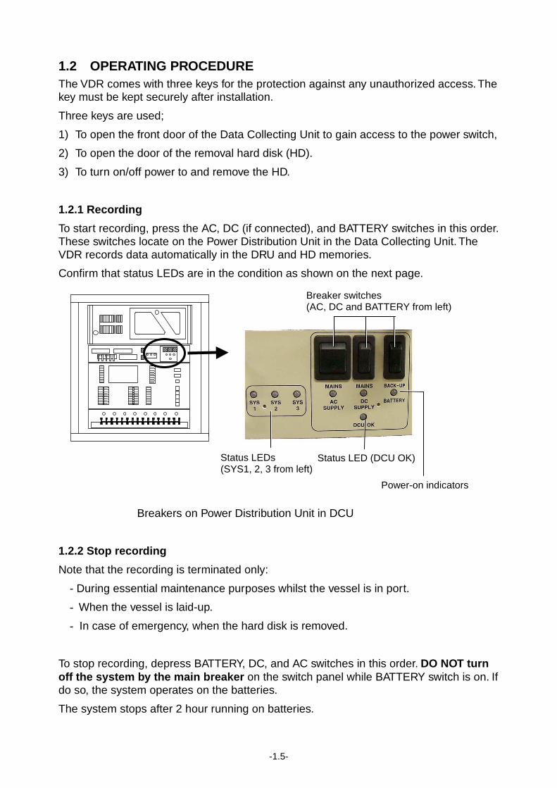
To start recording, press the AC, DC (if connected), and BATTERY switches in this order. These switches locate on the Power Distribution Unit in the Data Collecting Unit. The VDR records data automatically in the DRU and HD memories.
Confirm that status LEDs are in the condition as shown on the next page.
Breakers on Power Distribution Unit in DCU
1.2.2 Stop recording
Note that the recording is terminated only:
- During essential maintenance purposes whilst the vessel is in port.
- When the vessel is laid-up.
- In case of emergency, when the hard disk is removed.
To stop recording, depress BATTERY, DC, and AC switches in this order. DO NOT turn off the system by the main breaker on the switch panel while BATTERY switch is on. If do so, the system operates on the batteries.
The system stops after 2 hour running on batteries.
Breaker switches (AC, DC and BATTERY from left)
Status LEDs (SYS1, 2, 3 from left)
Power-on indicators
Status LED (DCU OK)
-1.6-
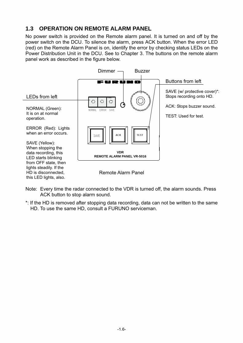
1.3 OPERATION ON REMOTE ALARM PANEL No power switch is provided on the Remote alarm panel. It is turned on and off by the power switch on the DCU. To silence the alarm, press ACK button. When the error LED (red) on the Remote Alarm Panel is on, identify the error by checking status LEDs on the Power Distribution Unit in the DCU. See to Chapter 3. The buttons on the remote alarm panel work as described in the figure below.
Remote Alarm Panel
Note: Every time the radar connected to the VDR is turned off, the alarm sounds. Press
ACK button to stop alarm sound.
*: If the HD is removed after stopping data recording, data can not be written to the same HD. To use the same HD, consult a FURUNO serviceman.
LEDs from left NORMAL (Green): It is on at normal operation. ERROR (Red): Lightswhen an error occurs. SAVE (Yellow): When stopping the data recording, this LED starts blinking from OFF state, then lights steadily. If the HD is disconnected, this LED lights, also.
Dimmer Buzzer
Buttons from left SAVE (w/ protective cover)*:Stops recording onto HD. ACK: Stops buzzer sound. TEST: Used for test.
VDR REMOTE ALARM PANEL VR-5016
-1.7-
1.4 LED STATUS
The LEDs on the Power Distribution Unit (PDU) operates as follows. Table 1.1 Status of LEDs
LEDs Status Remarks AC Green Presence of AC mains DC Green Presence of DC supply if connected BATTERY Green
(Blinking) Presence of DC from reserve battery (During charging)
DCU OK Green Normal operation of DCU processor (Red: NG) SYS 1 to 3 Orange No error
When the system diagnostic detects an error, the DCU OK lamp lights in red and SYS 1 to SYS 3 shows error details. See Chapter 3 for error codes.
1.5 COPY OF VDR INFORMATION
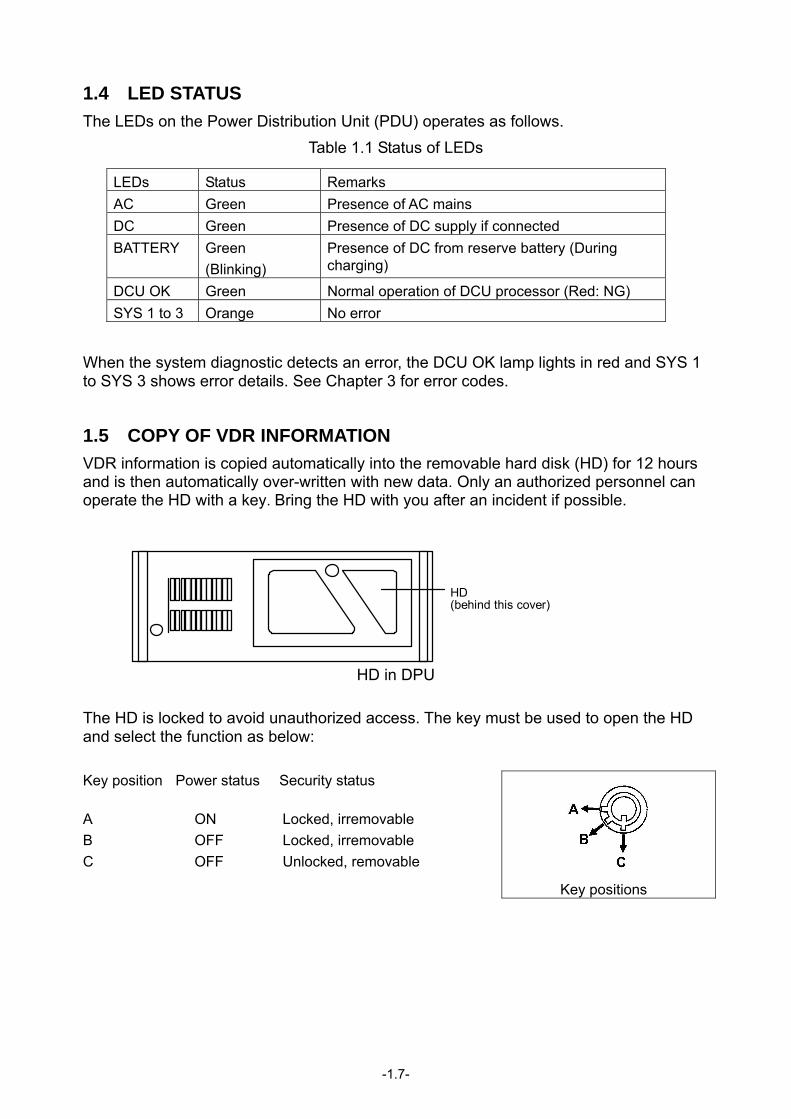
VDR information is copied automatically into the removable hard disk (HD) for 12 hours and is then automatically over-written with new data. Only an authorized personnel can operate the HD with a key. Bring the HD with you after an incident if possible.
HD in DPU The HD is locked to avoid unauthorized access. The key must be used to open the HD and select the function as below: Key position Power status Security status A ON Locked, irremovable B OFF Locked, irremovable C OFF Unlocked, removable
Key positions
HD (behind this cover)
-1.8-
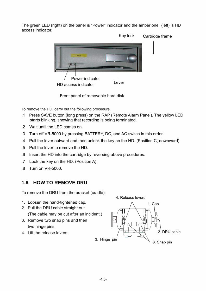
The green LED (right) on the panel is “Power” indicator and the amber one (left) is HD access indicator.
HD access indicator
Front panel of removable hard disk
To remove the HD, carry out the following procedure. .1 Press SAVE button (long press) on the RAP (Remote Alarm Panel). The yellow LED
starts blinking, showing that recording is being terminated.
.2 Wait until the LED comes on.
.3 Turn off VR-5000 by pressing BATTERY, DC, and AC switch in this order.
.4 Pull the lever outward and then unlock the key on the HD. (Position C, downward)
.5 Pull the lever to remove the HD.
.6 Insert the HD into the cartridge by reversing above procedures.
.7 Look the key on the HD. (Position A)
.8 Turn on VR-5000.
1.6 HOW TO REMOVE DRU To remove the DRU from the bracket (cradle); 1. Loosen the hand-tightened cap. 2. Pull the DRU cable straight out.
(The cable may be cut after an incident.) 3. Remove two snap pins and then
two hinge pins. 4. Lift the release levers.
2. DRU cable
1. Cap
3. Hinge pin 3. Snap pin
4. Release levers
Key lock Cartridge frame
Lever Power indicator
-2.1-
Chapter 2 MAINTENANCE Periodic checks and maintenance are important for proper operation of any electronic systems. This chapter contains maintenance instructions to be followed to obtain optimum performance and the longest possible life of the equipment. This chapter, except for 2.1 Routine check, is provided for a qualified personnel.
WARNINGELECTRICAL SHOCK HAZARDDo not open the equipment.
Only qualified personnelshould work inside theequipment.
Do not disassemble or modify theequipment.
Fire, electrical shock or serious injury canresult.
2.1 ROUTINE CHECK Periodically, carry out the following checks.
.1 Examine the cables for signs of damage, such as chafing, cuts or nicks.
.2 Check that all connections are tight. 2.2 REPLACEMENT OF BATTERY Every four years, the back-up battery must be replaced with new one by a qualified service engineer. Battery Type: VR-5015, requiring 2 pcs.
Code Number: 004-379-620 WARNING
- Do not attempt to dismantle the battery. If accidental skin/eye contact is made with the battery fluid, wash the affected area/part immediately with liberal amounts of clean fresh water and seek IMMEDIATE medical attention.
- DO NOT INCINERATE batteries as they are liable to rupture if placed into a fire. Batteries, that have reached the end of their service life, must be disposed in accordance with the local regulation.
- Touching electrically conductive parts might result in an electric shock. Be sure to wear rubber gloves before inspection or maintenance work.
- Mixing batteries with different capacity, different ages and different manufactures is liable to cause damage to the battery itself and/or the associated equipment.
- To obtain maximum life, batteries should never be shorted in a discharge state.
-2.2-
Note that the batteries should be recycled. Contact FURUNO dealer.
To replace the batteries;
.1 Open the front cover with the key.
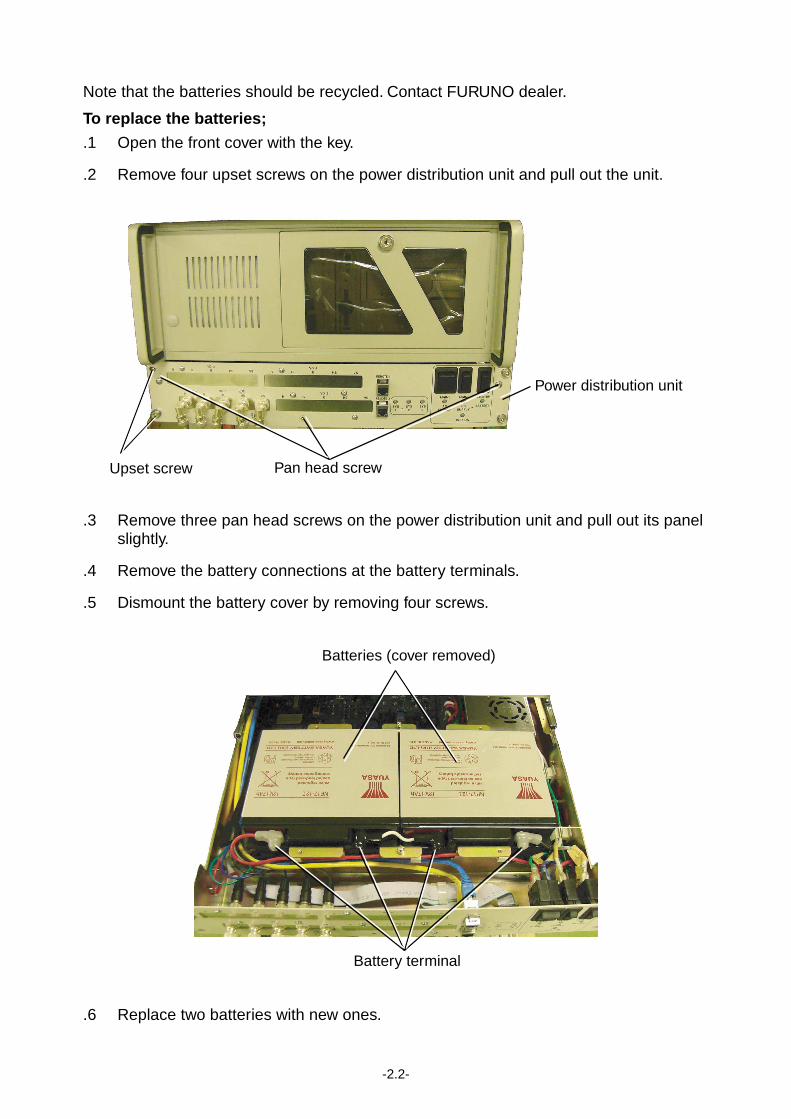
.2 Remove four upset screws on the power distribution unit and pull out the unit.
Upset screw Pan head screw
Power distribution unit
.3 Remove three pan head screws on the power distribution unit and pull out its panel slightly.
.4 Remove the battery connections at the battery terminals.
.5 Dismount the battery cover by removing four screws.
Batteries (cover removed)
Battery terminal
.6 Replace two batteries with new ones.
-2.3-
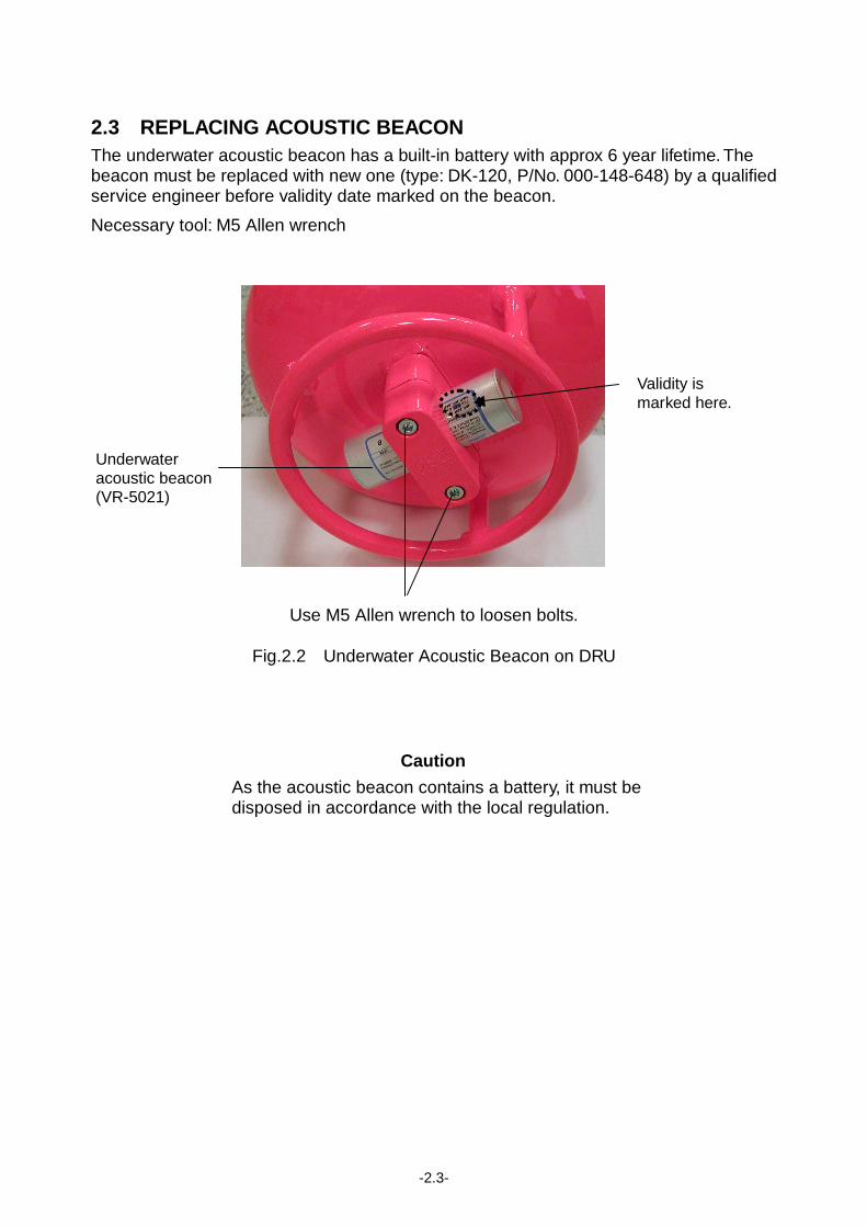
2.3 REPLACING ACOUSTIC BEACON The underwater acoustic beacon has a built-in battery with approx 6 year lifetime. The beacon must be replaced with new one (type: DK-120, P/No. 000-148-648) by a qualified service engineer before validity date marked on the beacon.
Necessary tool: M5 Allen wrench
Use M5 Allen wrench to loosen bolts.
Fig.2.2 Underwater Acoustic Beacon on DRU
Caution
As the acoustic beacon contains a battery, it must be disposed in accordance with the local regulation.
Validity is marked here.
Underwater acoustic beacon (VR-5021)
-3.1-
Chapter 3 TROUBLESHOOTING
This chapter provides information on possible causes of problems you may experience with your VDR. If you still have a problem after referring to the table, contact your local dealer or national distributor for further advice. Always provide the product serial number.
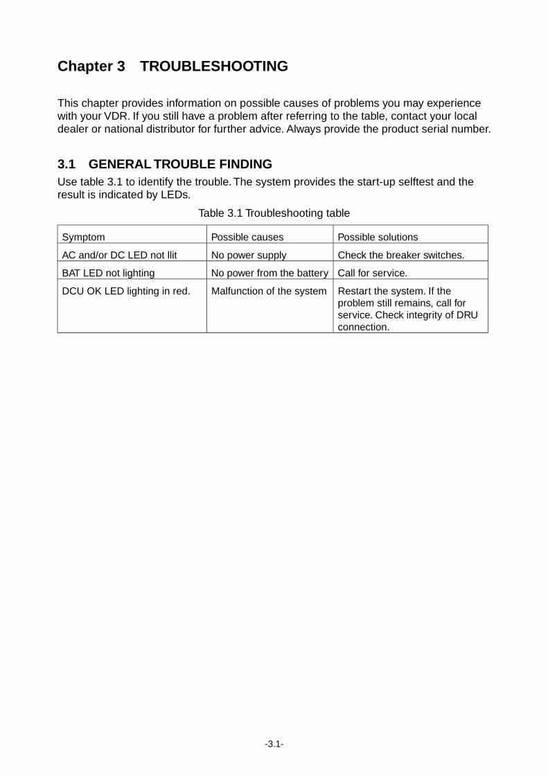
3.1 GENERAL TROUBLE FINDING Use table 3.1 to identify the trouble. The system provides the start-up selftest and the result is indicated by LEDs.
Table 3.1 Troubleshooting table
Symptom Possible causes Possible solutions
AC and/or DC LED not llit No power supply Check the breaker switches.
BAT LED not lighting No power from the battery Call for service.
DCU OK LED lighting in red. Malfunction of the system Restart the system. If the problem still remains, call for service. Check integrity of DRU connection.
-3.2-
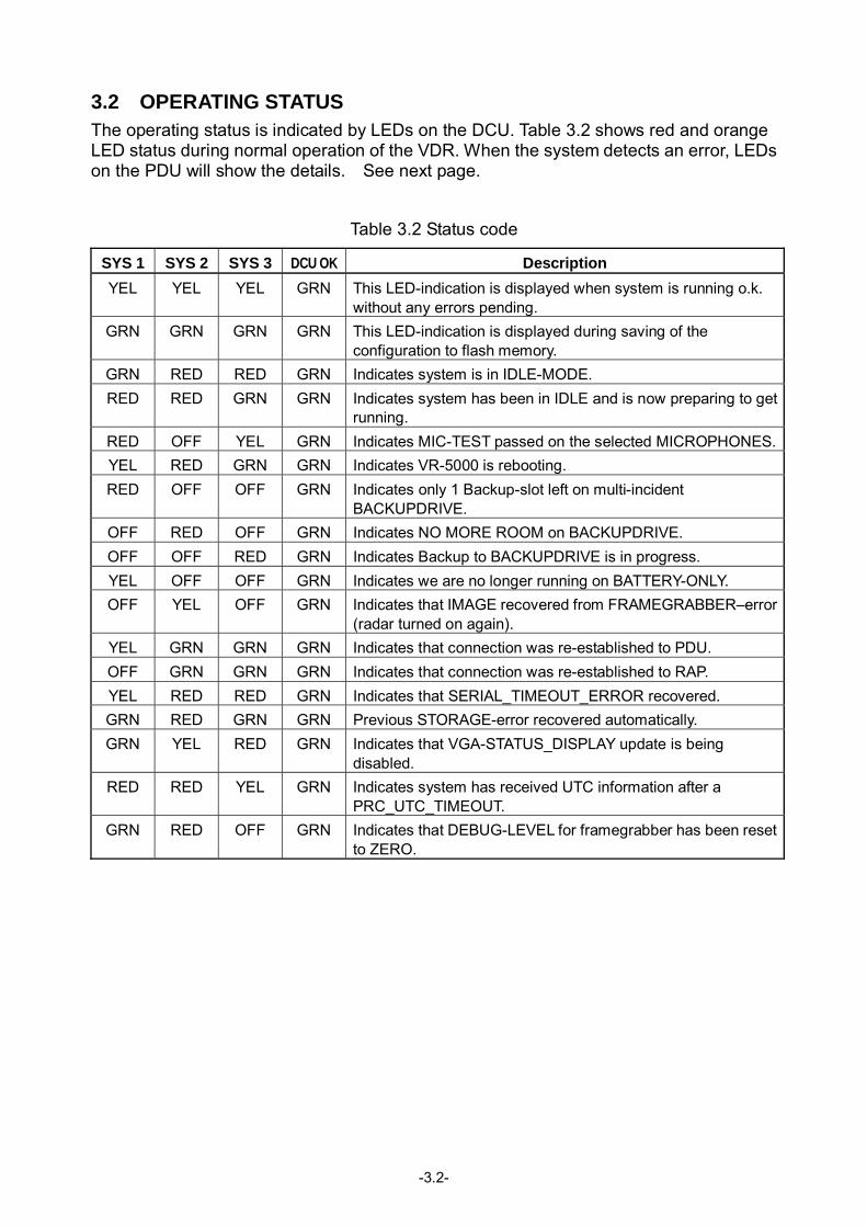
3.2 OPERATING STATUS The operating status is indicated by LEDs on the DCU. Table 3.2 shows red and orange LED status during normal operation of the VDR. When the system detects an error, LEDs on the PDU will show the details. See next page.
Table 3.2 Status code
SYS 1 SYS 2 SYS 3 DCU OK Description YEL YEL YEL GRN This LED-indication is displayed when system is running o.k.
without any errors pending. GRN GRN GRN GRN This LED-indication is displayed during saving of the
configuration to flash memory. GRN RED RED GRN Indicates system is in IDLE-MODE. RED RED GRN GRN Indicates system has been in IDLE and is now preparing to get
running. RED OFF YEL GRN Indicates MIC-TEST passed on the selected MICROPHONES.YEL RED GRN GRN Indicates VR-5000 is rebooting. RED OFF OFF GRN Indicates only 1 Backup-slot left on multi-incident
BACKUPDRIVE. OFF RED OFF GRN Indicates NO MORE ROOM on BACKUPDRIVE. OFF OFF RED GRN Indicates Backup to BACKUPDRIVE is in progress. YEL OFF OFF GRN Indicates we are no longer running on BATTERY-ONLY. OFF YEL OFF GRN Indicates that IMAGE recovered from FRAMEGRABBER–error
(radar turned on again). YEL GRN GRN GRN Indicates that connection was re-established to PDU. OFF GRN GRN GRN Indicates that connection was re-established to RAP. YEL RED RED GRN Indicates that SERIAL_TIMEOUT_ERROR recovered. GRN RED GRN GRN Previous STORAGE-error recovered automatically. GRN YEL RED GRN Indicates that VGA-STATUS_DISPLAY update is being
disabled. RED RED YEL GRN Indicates system has received UTC information after a
PRC_UTC_TIMEOUT. GRN RED OFF GRN Indicates that DEBUG-LEVEL for framegrabber has been reset
to ZERO.
-3.3-
SYS 1 SYS 2 SYS 3 DCU OK Code Name
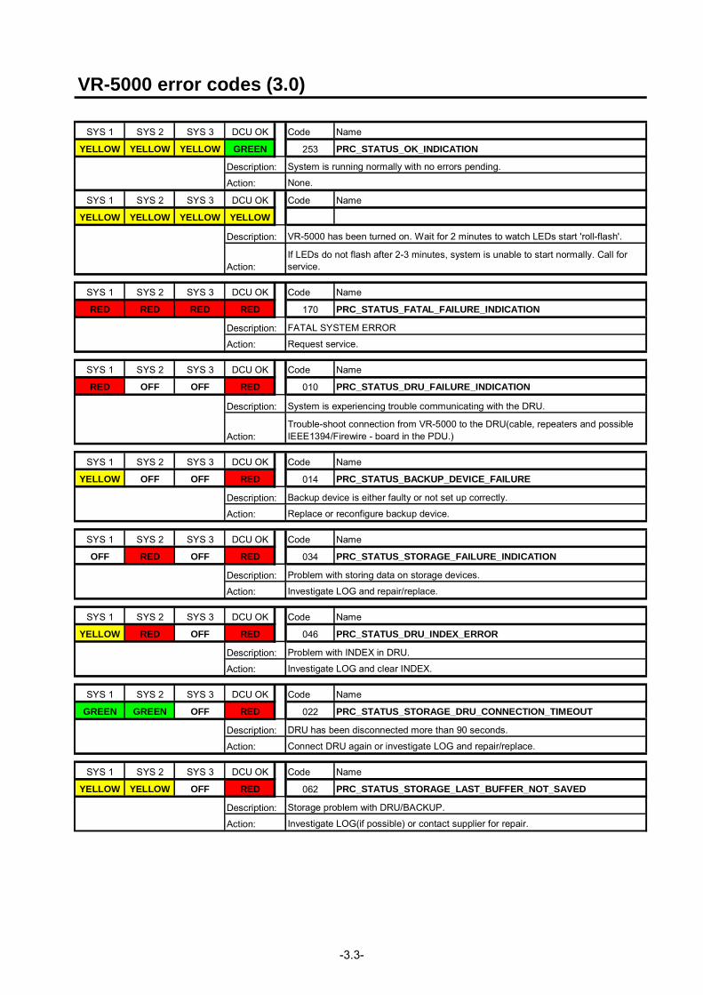
YELLOW YELLOW YELLOW GREEN 253 PRC_STATUS_OK_INDICATION
SYS 1 SYS 2 SYS 3 DCU OK Code Name
YELLOW YELLOW YELLOW YELLOW
SYS 1 SYS 2 SYS 3 DCU OK Code Name
RED RED RED RED 170 PRC_STATUS_FATAL_FAILURE_INDICATION
SYS 1 SYS 2 SYS 3 DCU OK Code Name
RED OFF OFF RED 010 PRC_STATUS_DRU_FAILURE_INDICATION
SYS 1 SYS 2 SYS 3 DCU OK Code Name
YELLOW OFF OFF RED 014 PRC_STATUS_BACKUP_DEVICE_FAILURE
SYS 1 SYS 2 SYS 3 DCU OK Code Name
OFF RED OFF RED 034 PRC_STATUS_STORAGE_FAILURE_INDICATION
SYS 1 SYS 2 SYS 3 DCU OK Code Name
YELLOW RED OFF RED 046 PRC_STATUS_DRU_INDEX_ERROR
SYS 1 SYS 2 SYS 3 DCU OK Code Name
GREEN GREEN OFF RED 022 PRC_STATUS_STORAGE_DRU_CONNECTION_TIMEOUT
SYS 1 SYS 2 SYS 3 DCU OK Code Name
YELLOW YELLOW OFF RED 062 PRC_STATUS_STORAGE_LAST_BUFFER_NOT_SAVED
VR-5000 error codes (3.0)
Description: System is running normally with no errors pending.
Action: None.
Description: VR-5000 has been turned on. Wait for 2 minutes to watch LEDs start 'roll-flash'.
Action:If LEDs do not flash after 2-3 minutes, system is unable to start normally. Call forservice.
Description: FATAL SYSTEM ERROR
Action: Request service.
Description: System is experiencing trouble communicating with the DRU.
Action:Trouble-shoot connection from VR-5000 to the DRU(cable, repeaters and possibleIEEE1394/Firewire - board in the PDU.)
Description: Backup device is either faulty or not set up correctly.
Action: Replace or reconfigure backup device.
Description: Problem with storing data on storage devices.
Action: Investigate LOG and repair/replace.
Description: Problem with INDEX in DRU.
Action: Investigate LOG and clear INDEX.
Description: DRU has been disconnected more than 90 seconds.
Action: Connect DRU again or investigate LOG and repair/replace.
Description: Storage problem with DRU/BACKUP.
Action: Investigate LOG(if possible) or contact supplier for repair.
-3.4-
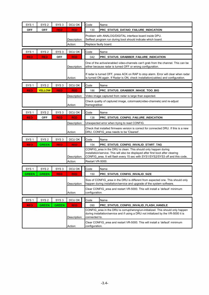
SYS 1 SYS 2 SYS 3 DCU OK Code Name
OFF OFF RED RED 130 PRC_STATUS_DATAIO_FAILURE_INDICATION
SYS 1 SYS 2 SYS 3 DCU OK Code Name
RED RED OFF RED 042 PRC_STATUS_GRABBER_FAILURE_INDICATION
SYS 1 SYS 2 SYS 3 DCU OK Code Name
RED YELLOW RED RED 186 PRC_STATUS_GRABBER_IMAGE_TOO_BIG
SYS 1 SYS 2 SYS 3 DCU OK Code Name
RED OFF RED RED 138 PRC_STATUS_CONFIG_FAILURE_INDICATION
SYS 1 SYS 2 SYS 3 DCU OK Code Name
RED GREEN RED RED 154 PRC_STATUS_CONFIG_INVALID_START_TAG
SYS 1 SYS 2 SYS 3 DCU OK Code Name
GREEN GREEN RED RED 150 PRC_STATUS_CONFIG_INVALID_SIZE
SYS 1 SYS 2 SYS 3 DCU OK Code Name
RED GREEN GREEN RED 090 PRC_STATUS_CONFIG_INVALID_FLASH_HANDLE
Description:Problem with ANALOG/DIGITAL interface board inside DPU.Selftest program run during boot should indicate which board.
Action: Replace faulty board.
Description:One of the active/enabled video-channels can't grab from the channel. This can beeither because radar is turned OFF or wrong configuration.
Action:If radar is turned OFF, press ACK on RAP to stop alarm. Error will clear when radaris turned ON again. If Radar is ON, check installation(cables) and configuration.
Description: Video image captured from radar is large than expected.
Action:Check quality of captured image, colormask(video-channels) and re-adjustframegrabber.
Description: Unexpected error when trying to read CONFIG.
Action:Check that installed firmware version is correct for connected DRU. If this is a newDRU, CONFIG_area needs to be 'Cleared'.
Description:
CONFIG_area in the DRU is clean. This should only happen duringinstallation/service. This will also be displayed after first boot after clearingCONFIG_area. It will flash every 15 sec with SYS1/SYS2/SYS3 off and this code.
Action: Restart VR-5000.
Description:Size of CONFIG_area in the DRU is different from expected one. This should onlyhappen during installation/service and upgrade of the system software.
Action:Clear CONFIG_area and restart VR-5000. This will install a ’default’ minimumconfiguration.
Description:
CONFIG_area in the DRU is corrupt/wrong/un-initialized. This should only happenduring installation/service and if using a DRU not initialized by the VR-5000 it isconnected to.
Action:Clear CONFIG_area and restart VR-5000. This will install a ’default’ minimumconfiguration.
-3.5-
SYS 1 SYS 2 SYS 3 DCU OK Code Name
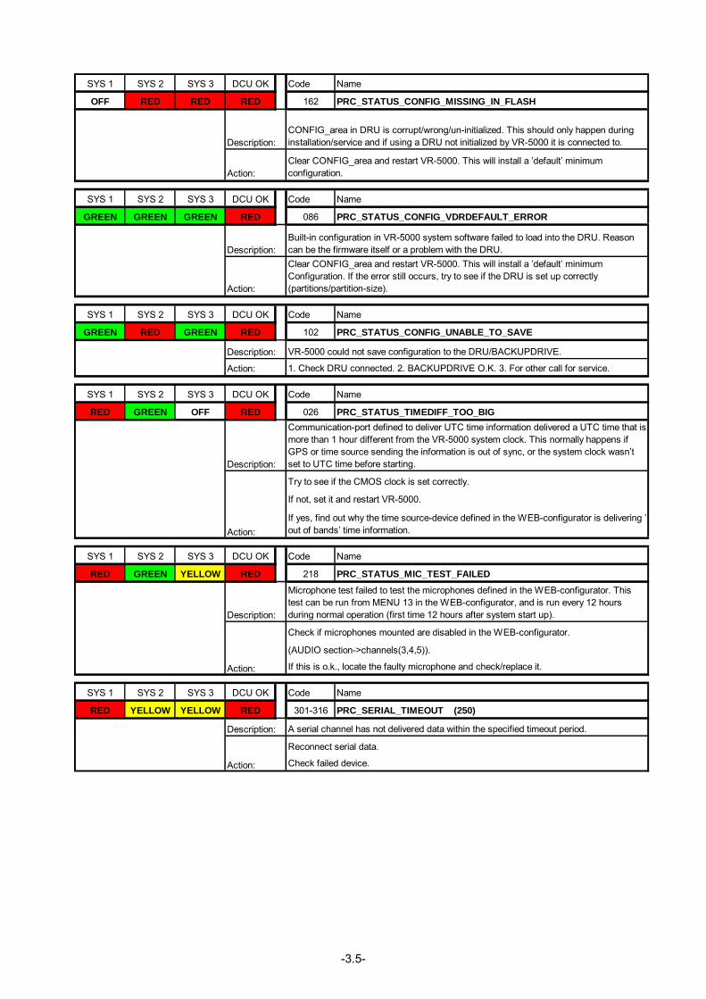
OFF RED RED RED 162 PRC_STATUS_CONFIG_MISSING_IN_FLASH
SYS 1 SYS 2 SYS 3 DCU OK Code Name
GREEN GREEN GREEN RED 086 PRC_STATUS_CONFIG_VDRDEFAULT_ERROR
SYS 1 SYS 2 SYS 3 DCU OK Code Name
GREEN RED GREEN RED 102 PRC_STATUS_CONFIG_UNABLE_TO_SAVE
SYS 1 SYS 2 SYS 3 DCU OK Code Name
RED GREEN OFF RED 026 PRC_STATUS_TIMEDIFF_TOO_BIG
SYS 1 SYS 2 SYS 3 DCU OK Code Name
RED GREEN YELLOW RED 218 PRC_STATUS_MIC_TEST_FAILED
SYS 1 SYS 2 SYS 3 DCU OK Code Name
RED YELLOW YELLOW RED 301-316 PRC_SERIAL_TIMEOUT (250)
Description: A serial channel has not delivered data within the specified timeout period.
Action:
Reconnect serial data.
Check failed device.
Action:
Description:
Microphone test failed to test the microphones defined in the WEB-configurator. Thistest can be run from MENU 13 in the WEB-configurator, and is run every 12 hoursduring normal operation (first time 12 hours after system start up).
Check if microphones mounted are disabled in the WEB-configurator.
(AUDIO section->channels(3,4,5)).
If this is o.k., locate the faulty microphone and check/replace it.
Description:
Communication-port defined to deliver UTC time information delivered a UTC time that ismore than 1 hour different from the VR-5000 system clock. This normally happens ifGPS or time source sending the information is out of sync, or the system clock wasn’tset to UTC time before starting.
Action:
Try to see if the CMOS clock is set correctly.
If not, set it and restart VR-5000.
If yes, find out why the time source-device defined in the WEB-configurator is delivering ’out of bands’ time information.
Description: VR-5000 could not save configuration to the DRU/BACKUPDRIVE.
Action: 1. Check DRU connected. 2. BACKUPDRIVE O.K. 3. For other call for service.
Description:Built-in configuration in VR-5000 system software failed to load into the DRU. Reasoncan be the firmware itself or a problem with the DRU.
Action:
Clear CONFIG_area and restart VR-5000. This will install a ’default’ minimumConfiguration. If the error still occurs, try to see if the DRU is set up correctly(partitions/partition-size).
Description:CONFIG_area in DRU is corrupt/wrong/un-initialized. This should only happen duringinstallation/service and if using a DRU not initialized by VR-5000 it is connected to.
Action:Clear CONFIG_area and restart VR-5000. This will install a ’default’ minimumconfiguration.
-3.6-
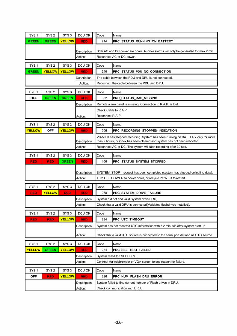
SYS 1 SYS 2 SYS 3 DCU OK Code Name
GREEN GREEN YELLOW RED 214 PRC_STATUS_RUNNING_ON_BATTERY
SYS 1 SYS 2 SYS 3 DCU OK Code Name
GREEN YELLOW YELLOW RED 246 PRC_STATUS_PDU_NO_CONNECTION
Description:
Action:
SYS 1 SYS 2 SYS 3 DCU OK Code Name
OFF GREEN GREEN RED 082 PRC_STATUS_RAP_MISSING
SYS 1 SYS 2 SYS 3 DCU OK Code Name
YELLOW OFF YELLOW RED 206 PRC_RECORDING_STOPPED_INDICATION
SYS 1 SYS 2 SYS 3 DCU OK Code Name
RED RED GREEN RED 106 PRC_STATUS_SYSTEM_STOPPED
SYS 1 SYS 2 SYS 3 DCU OK Code Name
RED YELLOW RED RED 238 PRC_SYSTEM_DRIVE_FAILURE
SYS 1 SYS 2 SYS 3 DCU OK Code Name
RED RED YELLOW RED 234 PRC_UTC_TIMEOUT
SYS 1 SYS 2 SYS 3 DCU OK Code Name
YELLOW GREEN YELLOW RED 254 PRC_SELFTEST_FAILED
SYS 1 SYS 2 SYS 3 DCU OK Code Name
OFF RED YELLOW RED 226 PRC_NUM_FLASH_DRU_ERROR
Description: System failed to find correct number of Flash drives in DRU.
Action: Check communication with DRU.
Description: System failed the SELFTEST.
Action: Connect via webbrowser or VGA screen to see reason for failure.
Description: System has not received UTC information within 2 minutes after system start up.
Action: Check that a valid UTC source is connected to the serial port defined as UTC source.
Description: System did not find valid System drive(DRU).
Action: Check that a valid DRU is connected(Validated flashdrives installed).
Description: SYSTEM_STOP - request has been completed (system has stopped collecting data).
Action: Turn OFF POWER to power down, or recycle POWER to restart
Description:VR-5000 has stopped recording. System has been running on BATTERY only for morethan 2 hours, or index has been cleared and system has not been rebooted.
Action: Reconnect AC or DC. The system will start recording after 30 sec.
The cable between the PDU and DPU is not connected.
Reconnect the cable between the PDU and DPU.
Description: Remote alarm panel is missing. Connection to R.A.P. is lost.
Action:
Check Cable to R.A.P.
Reconnect R.A.P.
Description: Both AC and DC power are down. Audible alarms will only be generated for max 2 min.
Action: Reconnect AC or DC power.
-4.1-
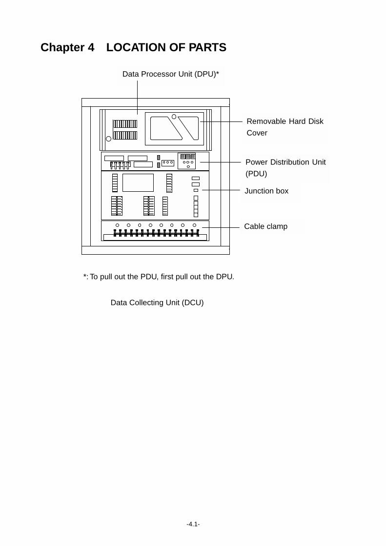
Chapter 4 LOCATION OF PARTS
*: To pull out the PDU, first pull out the DPU.
Data Collecting Unit (DCU)
Data Processor Unit (DPU)*
Removable Hard Disk
Cover
Power Distribution Unit
(PDU)
Junction box
Cable clamp
-4.2-
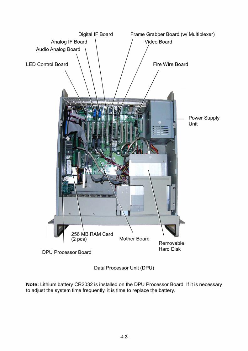
Digital IF Board Frame Grabber Board (w/ Multiplexer) Analog IF Board Video Board Audio Analog Board LED Control Board Fire Wire Board
Data Processor Unit (DPU)
Note: Lithium battery CR2032 is installed on the DPU Processor Board. If it is necessary to adjust the system time frequently, it is time to replace the battery.
Mother Board
Power Supply Unit
Removable Hard Disk
256 MB RAM Card(2 pcs)
DPU Processor Board
-4.3-
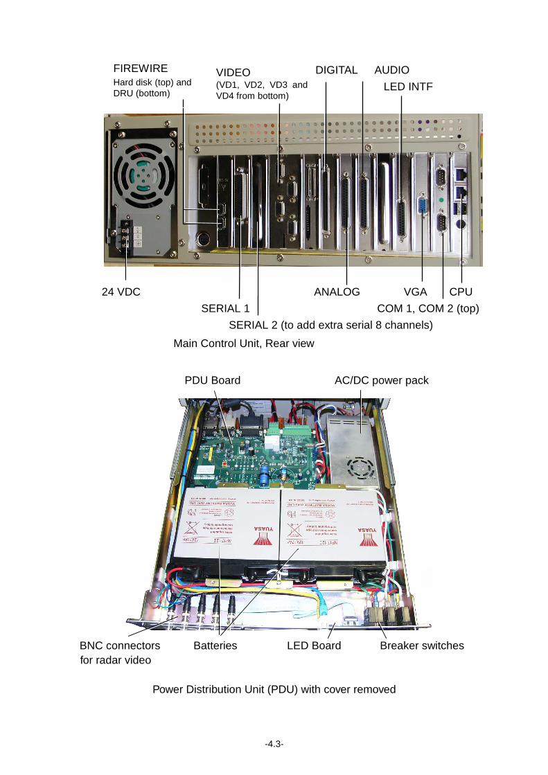
DIGITAL AUDIO
LED INTF
24 VDC ANALOG VGA CPU SERIAL 1 COM 1, COM 2 (top)
SERIAL 2 (to add extra serial 8 channels)
Main Control Unit, Rear view
PDU Board AC/DC power pack
BNC connectors Batteries LED Board Breaker switches for radar video
Power Distribution Unit (PDU) with cover removed
FIREWIRE Hard disk (top) and DRU (bottom)
VIDEO (VD1, VD2, VD3 andVD4 from bottom)
-4.4-
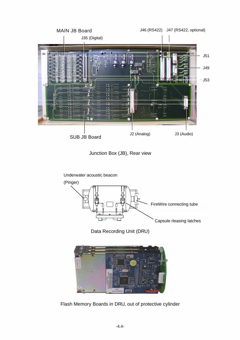
MAIN JB Board
SUB JB Board
Junction Box (JB), Rear view
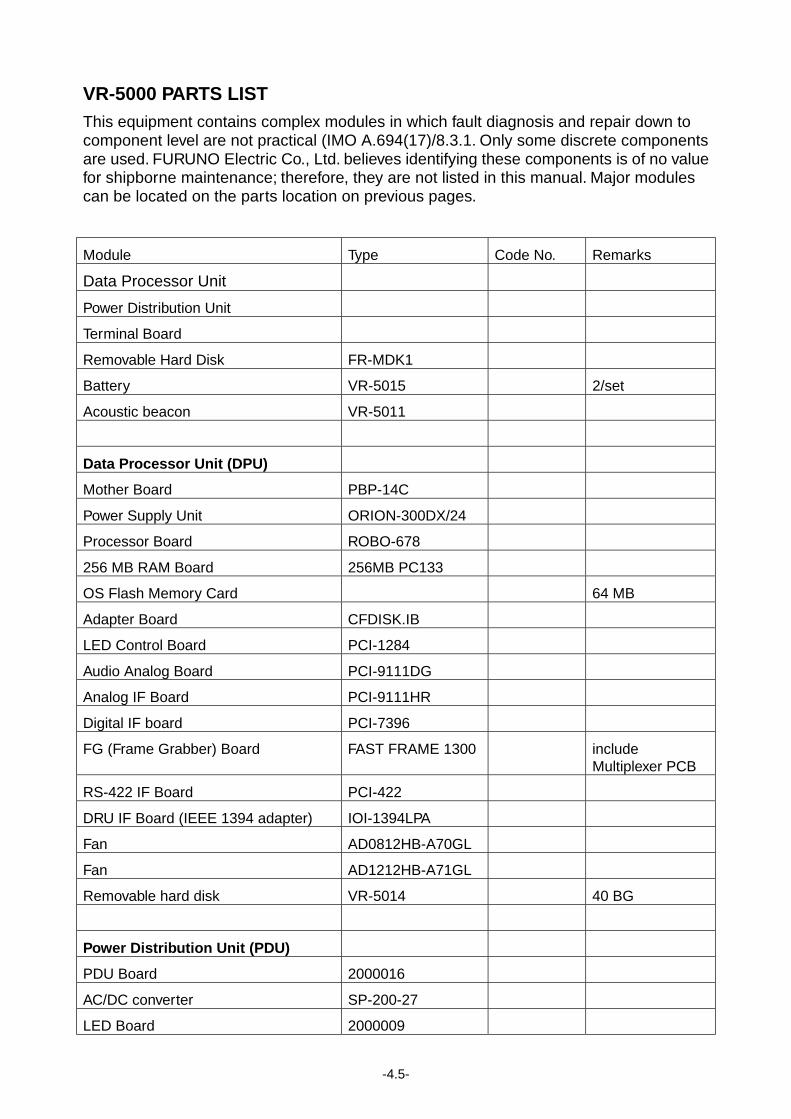
Capsule rleasing latches
Underwater acoustic beacon (Pinger)
FireWire connecting tube
Data Recording Unit (DRU)
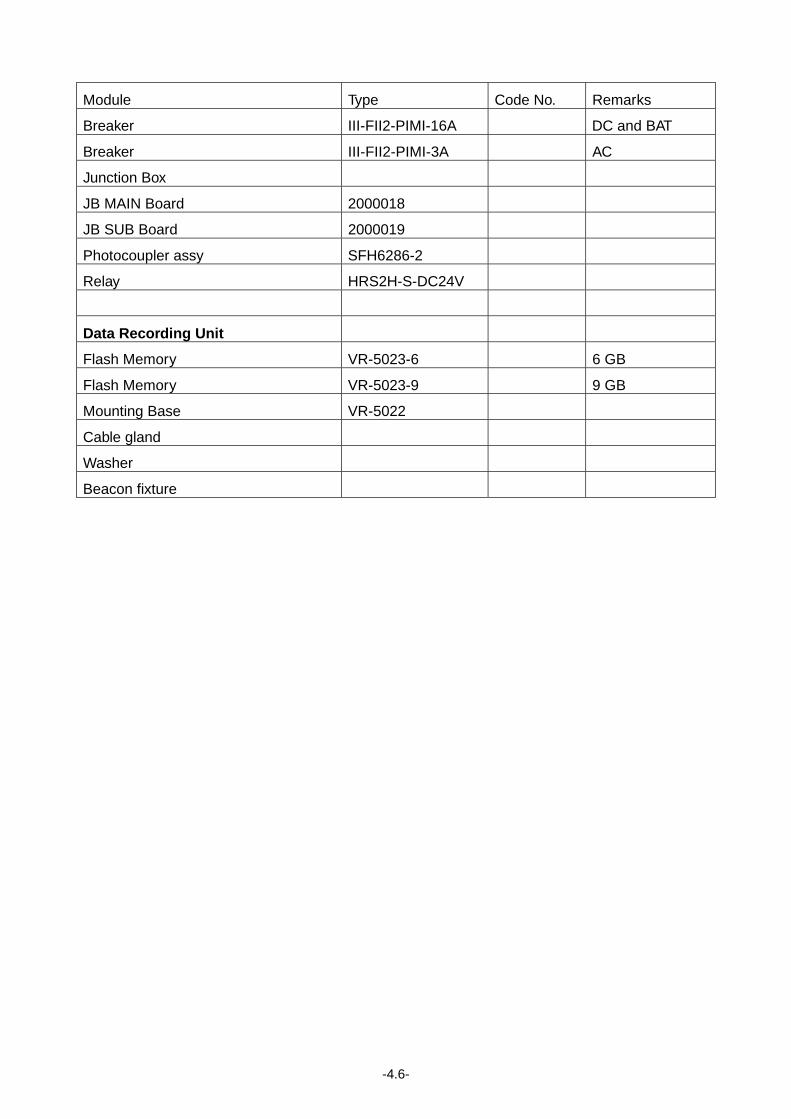
Flash Memory Boards in DRU, out of protective cylinder
J46 (RS422) J47 (RS422, optional)
J51
J49
J53
J35 (Digital)
J2 (Analog) J3 (Audio)
-4.5-
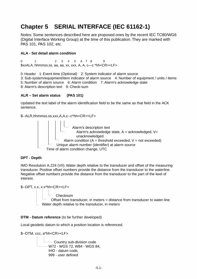
VR-5000 PARTS LIST This equipment contains complex modules in which fault diagnosis and repair down to component level are not practical (IMO A.694(17)/8.3.1. Only some discrete components are used. FURUNO Electric Co., Ltd. believes identifying these components is of no value for shipborne maintenance; therefore, they are not listed in this manual. Major modules can be located on the parts location on previous pages.
Module Type Code No. Remarks
Data Processor Unit
Power Distribution Unit
Terminal Board
Removable Hard Disk FR-MDK1
Battery VR-5015 2/set
Acoustic beacon VR-5011
Data Processor Unit (DPU)
Mother Board PBP-14C
Power Supply Unit ORION-300DX/24
Processor Board ROBO-678
256 MB RAM Board 256MB PC133
OS Flash Memory Card 64 MB
Adapter Board CFDISK.IB
LED Control Board PCI-1284
Audio Analog Board PCI-9111DG
Analog IF Board PCI-9111HR
Digital IF board PCI-7396
FG (Frame Grabber) Board FAST FRAME 1300 include Multiplexer PCB
RS-422 IF Board PCI-422
DRU IF Board (IEEE 1394 adapter) IOI-1394LPA
Fan AD0812HB-A70GL
Fan AD1212HB-A71GL
Removable hard disk VR-5014 40 BG
Power Distribution Unit (PDU)
PDU Board 2000016
AC/DC converter SP-200-27
LED Board 2000009
-4.6-
Module Type Code No. Remarks
Breaker III-FII2-PIMI-16A DC and BAT
Breaker III-FII2-PIMI-3A AC
Junction Box
JB MAIN Board 2000018
JB SUB Board 2000019
Photocoupler assy SFH6286-2
Relay HRS2H-S-DC24V
Data Recording Unit
Flash Memory VR-5023-6 6 GB
Flash Memory VR-5023-9 9 GB
Mounting Base VR-5022
Cable gland
Washer
Beacon fixture
-5.1-
Chapter 5 SERIAL INTERFACE (IEC 61162-1) Notes: Some sentences described here are proposed ones by the recent IEC TC80/WG6 (Digital Interface Working Group) at the time of this publication. They are marked with PAS 101, PAS 102, etc. ALA - Set detail alarm condition 0 1 2 3 4 5 6 7 8 9 $xxALA, hhmmss.ss, aa, aa, xx, xxx, A, A, c—c *hh<CR><LF> 0: Header 1: Event time (Optional) 2: System indicator of alarm source 3: Sub-system/equipment/item indicator of alarm source 4: Number of equipment / units / items 5: Number of alarm source 6: Alarm condition 7: Alarm’s acknowledge state 8: Alarm’s description text 9: Check-sum ALR – Set alarm status (PAS 101) Updated the text label of the alarm identification field to be the same as that field in the ACK sentence. $--ALR,hhmmss.ss,xxx,A,A,c--c*hh<CR><LF>
Alarm’s description text Alarm’s acknowledge state, A = acknowledged, V= unacknowledged
Alarm condition (A = threshold exceeded, V = not exceeded) Unique alarm number (identifier) at alarm source Time of alarm condition change, UTC DPT - Depth IMO Resolution A.224 (VII). Water depth relative to the transducer and offset of the measuring transducer. Positive offset numbers provide the distance from the transducer to the waterline. Negative offset numbers provide the distance from the transducer to the part of the keel of interest. $--DPT, x.x, x.x*hh<CR><LF> Checksum Offset from transducer, in meters = distance from transducer to water-line Water depth relative to the transducer, in meters DTM - Datum reference (to be further developed) Local geodetic datum to which a position location is referenced. $--DTM, ccc, a*hh<CR><LF> Country sub-division code W72 - WGS 72, W84 - WGS 84, IHO - datum code, 999 - user defined
-5.2-
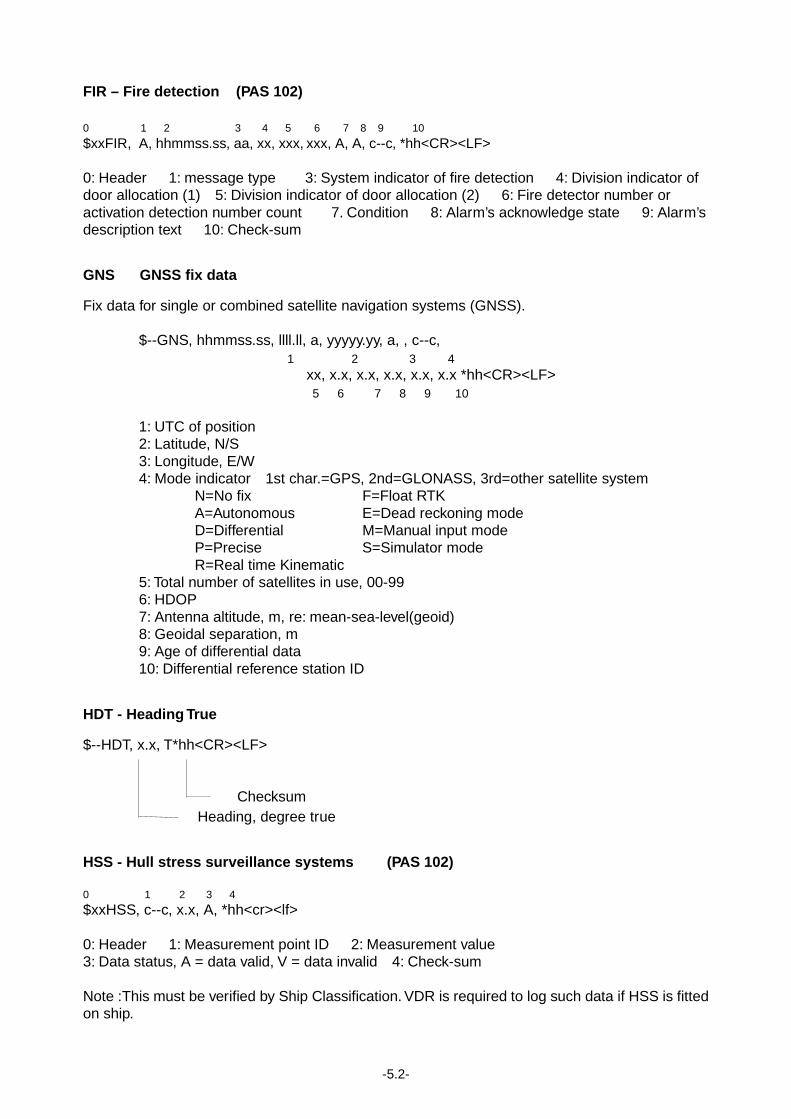
FIR – Fire detection (PAS 102)
0 1 2 3 4 5 6 7 8 9 10
$xxFIR, A, hhmmss.ss, aa, xx, xxx, xxx, A, A, c--c, *hh<CR><LF> 0: Header 1: message type 3: System indicator of fire detection 4: Division indicator of door allocation (1) 5: Division indicator of door allocation (2) 6: Fire detector number or activation detection number count 7. Condition 8: Alarm’s acknowledge state 9: Alarm’s description text 10: Check-sum GNS GNSS fix data Fix data for single or combined satellite navigation systems (GNSS). $--GNS, hhmmss.ss, llll.ll, a, yyyyy.yy, a, , c--c, 1 2 3 4 xx, x.x, x.x, x.x, x.x, x.x *hh<CR><LF> 5 6 7 8 9 10 1: UTC of position 2: Latitude, N/S 3: Longitude, E/W 4: Mode indicator 1st char.=GPS, 2nd=GLONASS, 3rd=other satellite system N=No fix F=Float RTK A=Autonomous E=Dead reckoning mode D=Differential M=Manual input mode P=Precise S=Simulator mode R=Real time Kinematic 5: Total number of satellites in use, 00-99 6: HDOP 7: Antenna altitude, m, re: mean-sea-level(geoid) 8: Geoidal separation, m 9: Age of differential data 10: Differential reference station ID HDT - Heading True $--HDT, x.x, T*hh<CR><LF> Checksum Heading, degree true HSS - Hull stress surveillance systems (PAS 102)
0 1 2 3 4
$xxHSS, c--c, x.x, A, *hh<cr><lf> 0: Header 1: Measurement point ID 2: Measurement value 3: Data status, A = data valid, V = data invalid 4: Check-sum Note :This must be verified by Ship Classification. VDR is required to log such data if HSS is fitted on ship.
-5.3-
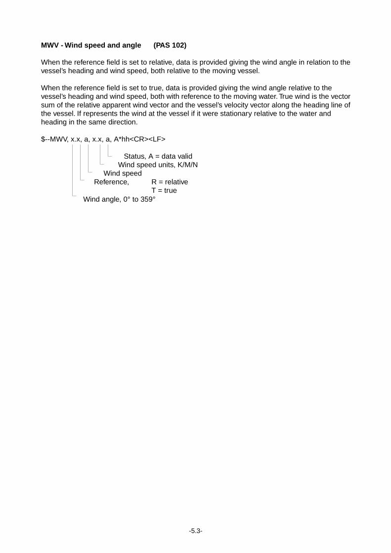
MWV - Wind speed and angle (PAS 102) When the reference field is set to relative, data is provided giving the wind angle in relation to the vessel’s heading and wind speed, both relative to the moving vessel. When the reference field is set to true, data is provided giving the wind angle relative to the vessel’s heading and wind speed, both with reference to the moving water. True wind is the vector sum of the relative apparent wind vector and the vessel’s velocity vector along the heading line of the vessel. If represents the wind at the vessel if it were stationary relative to the water and heading in the same direction. $--MWV, x.x, a, x.x, a, A*hh<CR><LF> Status, A = data valid Wind speed units, K/M/N Wind speed Reference, R = relative T = true Wind angle, 0° to 359°
-5.4-
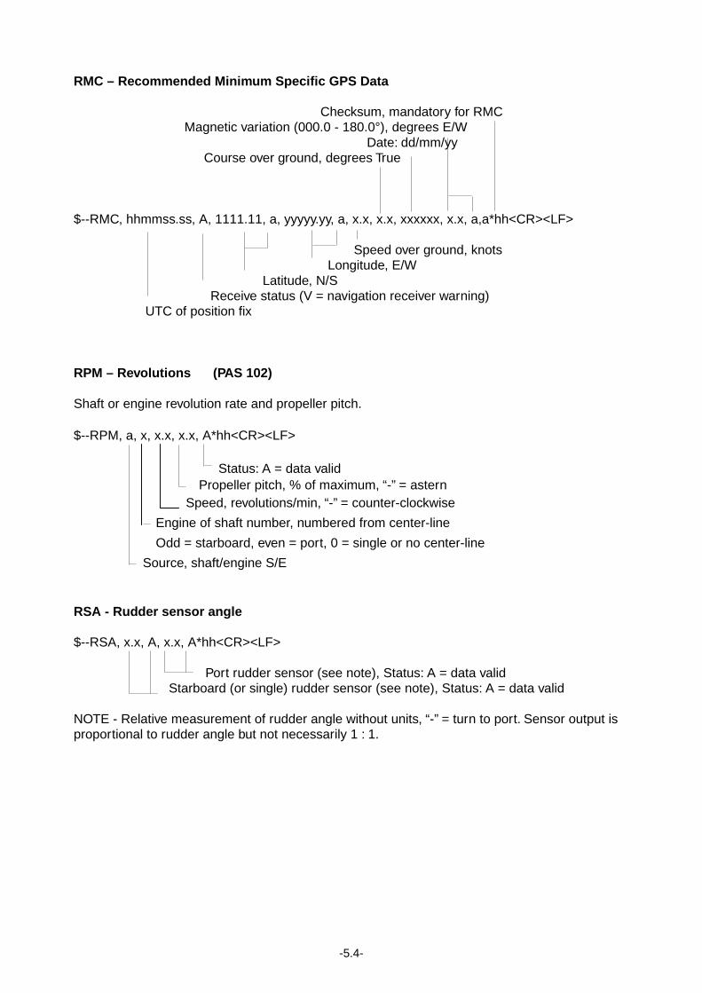
RMC – Recommended Minimum Specific GPS Data
Checksum, mandatory for RMC Magnetic variation (000.0 - 180.0°), degrees E/W Date: dd/mm/yy Course over ground, degrees True $--RMC, hhmmss.ss, A, 1111.11, a, yyyyy.yy, a, x.x, x.x, xxxxxx, x.x, a,a*hh<CR><LF> Speed over ground, knots Longitude, E/W Latitude, N/S Receive status (V = navigation receiver warning) UTC of position fix RPM – Revolutions (PAS 102) Shaft or engine revolution rate and propeller pitch. $--RPM, a, x, x.x, x.x, A*hh<CR><LF> Status: A = data valid Propeller pitch, % of maximum, “-” = astern Speed, revolutions/min, “-” = counter-clockwise
Engine of shaft number, numbered from center-line
Odd = starboard, even = port, 0 = single or no center-line
Source, shaft/engine S/E RSA - Rudder sensor angle $--RSA, x.x, A, x.x, A*hh<CR><LF> Port rudder sensor (see note), Status: A = data valid Starboard (or single) rudder sensor (see note), Status: A = data valid NOTE - Relative measurement of rudder angle without units, “-” = turn to port. Sensor output is proportional to rudder angle but not necessarily 1 : 1.
-5.5-
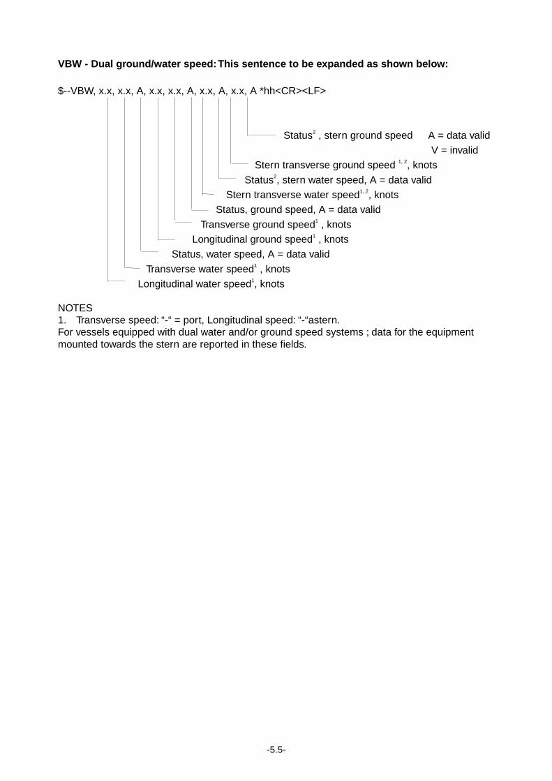
VBW - Dual ground/water speed: This sentence to be expanded as shown below: $--VBW, x.x, x.x, A, x.x, x.x, A, x.x, A, x.x, A *hh<CR><LF>
Status2 , stern ground speed A = data valid
V = invalid
Stern transverse ground speed 1, 2, knots
Status2, stern water speed, A = data valid
Stern transverse water speed1, 2, knots
Status, ground speed, A = data valid
Transverse ground speed1 , knots
Longitudinal ground speed1 , knots
Status, water speed, A = data valid
Transverse water speed1 , knots
Longitudinal water speed1, knots NOTES 1. Transverse speed: “-“ = port, Longitudinal speed: “-“astern. For vessels equipped with dual water and/or ground speed systems ; data for the equipment mounted towards the stern are reported in these fields.
-5.6-
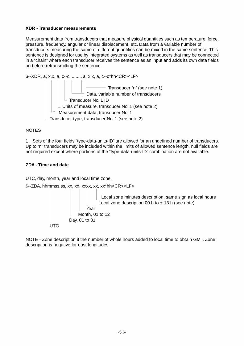
XDR - Transducer measurements Measurement data from transducers that measure physical quantities such as temperature, force, pressure, frequency, angular or linear displacement, etc. Data from a variable number of transducers measuring the same of different quantities can be mixed in the same sentence. This sentence is designed for use by integrated systems as well as transducers that may be connected in a “chain” where each transducer receives the sentence as an input and adds its own data fields on before retransmitting the sentence. $--XDR, a, x.x, a, c--c, ........ a, x.x, a, c--c*hh<CR><LF> Transducer “n” (see note 1) Data, variable number of transducers Transducer No. 1 ID Units of measure, transducer No. 1 (see note 2) Measurement data, transducer No. 1 Transducer type, transducer No. 1 (see note 2) NOTES 1 Sets of the four fields “type-data-units-ID” are allowed for an undefined number of transducers. Up to “n” transducers may be included within the limits of allowed sentence length, null fields are not required except where portions of the “type-data-units-ID” combination are not available.
ZDA - Time and date
UTC, day, month, year and local time zone.
$--ZDA. hhmmss.ss, xx, xx, xxxx, xx, xx*hh<CR><LF> Local zone minutes description, same sign as local hours Local zone description 00 h to ± 13 h (see note) Year Month, 01 to 12 Day, 01 to 31 UTC
NOTE - Zone description if the number of whole hours added to local time to obtain GMT. Zone description is negative for east longitudes.

The paper used in this manualis elemental chlorine free.
FURUNO Authorized Distributor/DealerFURUNO Authorized Distributor/Dealer
9-52 Ashihara-cho,9-52 Ashihara-cho,Nishinomiya 662-8580, JAPANNishinomiya 662-8580, JAPAN
Telephone :Telephone : 0798-65-21110798-65-2111FaxFax 0798-65-42000798-65-4200::
FIRST EDITION :FIRST EDITION : APR.APR. 20032003Printed in JapanPrinted in JapanAll rights reserved.All rights reserved.EE ::AUG.AUG. 24, 200524, 2005
Pub. No.Pub. No. OME-44180OME-44180*00014820303**00014820303**00014820303**00014820303*(( TATATATA )) VR-5000VR-5000
* 0 0 0 1 4 8 2 0 3 0 3 ** 0 0 0 1 4 8 2 0 3 0 3 *
*OME44180E00**OME44180E00**OME44180E00**OME44180E00*
* O M E 4 4 1 8 0 E 0 0 ** O M E 4 4 1 8 0 E 0 0 *