Embed Size (px)
Citation preview

Vortok Rotorrail
Maintenance Free Switch Roller Systems Rotorrail is manufactured under licence from Mazzi Technology S.R.L.
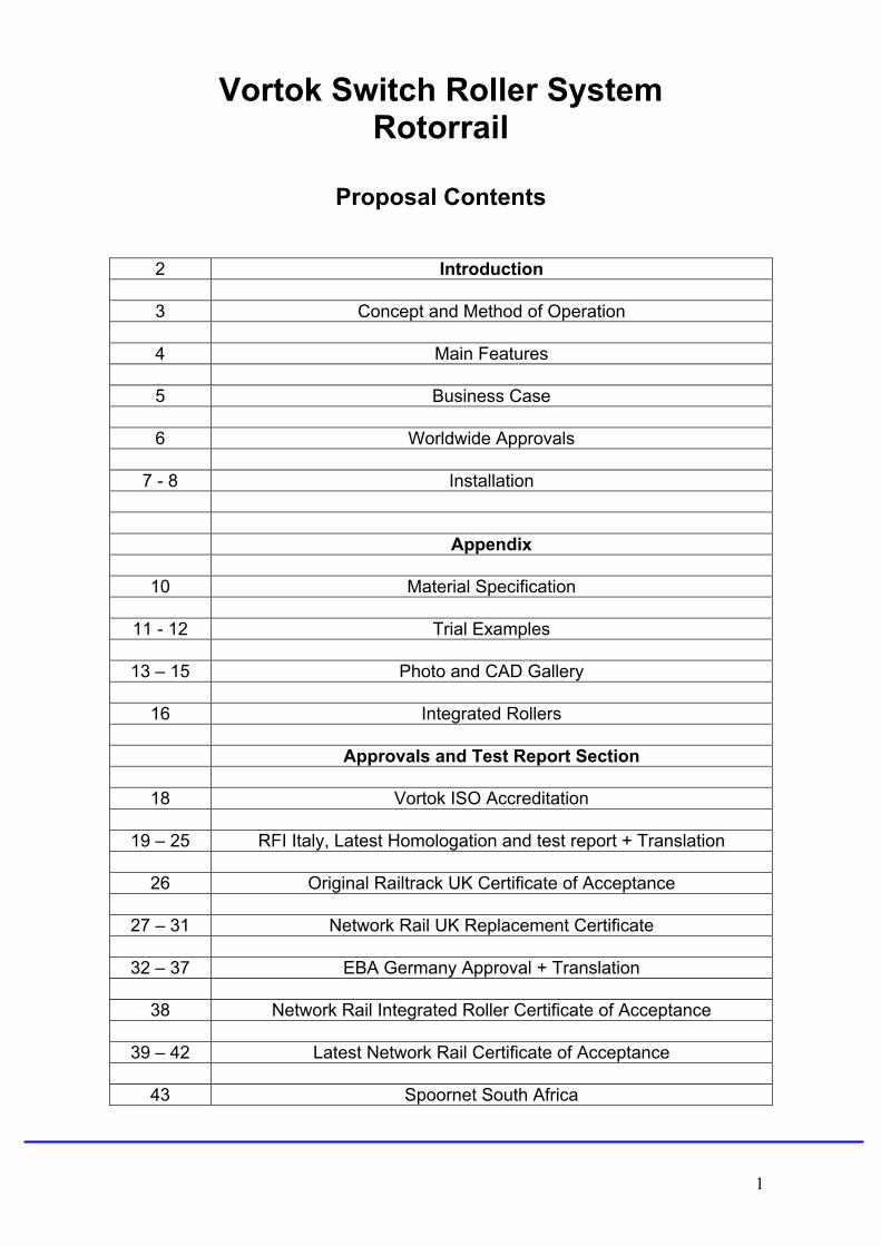
Vortok Switch Roller System Rotorrail
Proposal Contents
2 Introduction
3 Concept and Method of Operation
4 Main Features
5 Business Case
6 Worldwide Approvals
7 - 8 Installation Appendix
10 Material Specification
11 - 12 Trial Examples
13 – 15 Photo and CAD Gallery
16 Integrated Rollers Approvals and Test Report Section
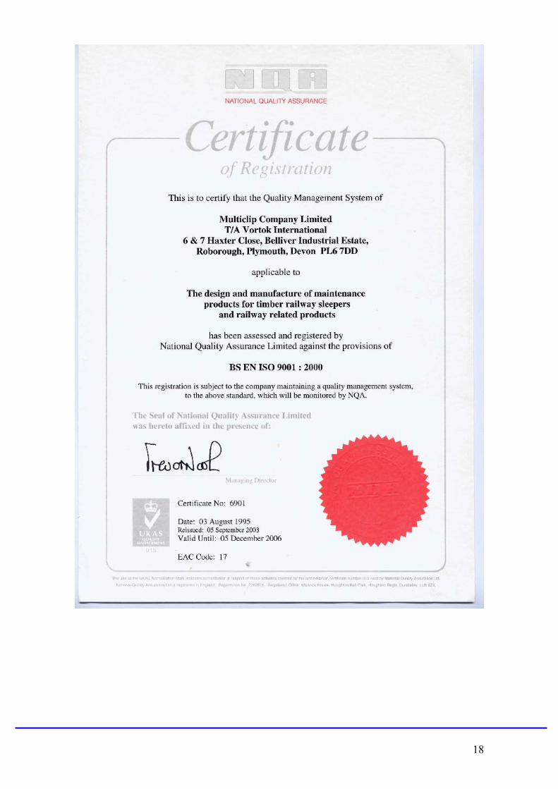
18 Vortok ISO Accreditation
19 – 25 RFI Italy, Latest Homologation and test report + Translation
26 Original Railtrack UK Certificate of Acceptance
27 – 31 Network Rail UK Replacement Certificate
32 – 37 EBA Germany Approval + Translation
38 Network Rail Integrated Roller Certificate of Acceptance
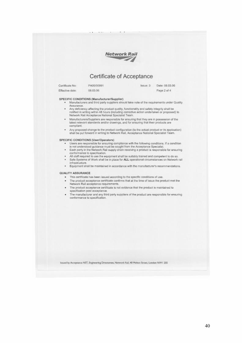
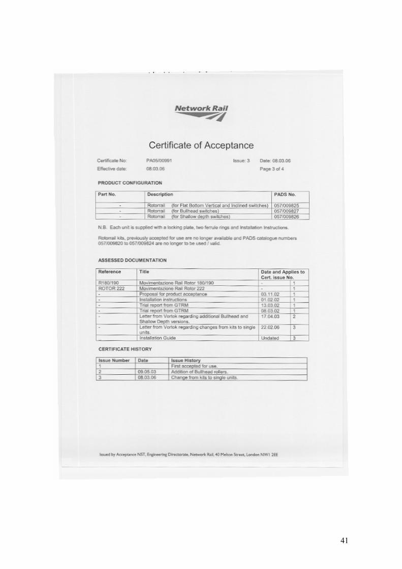
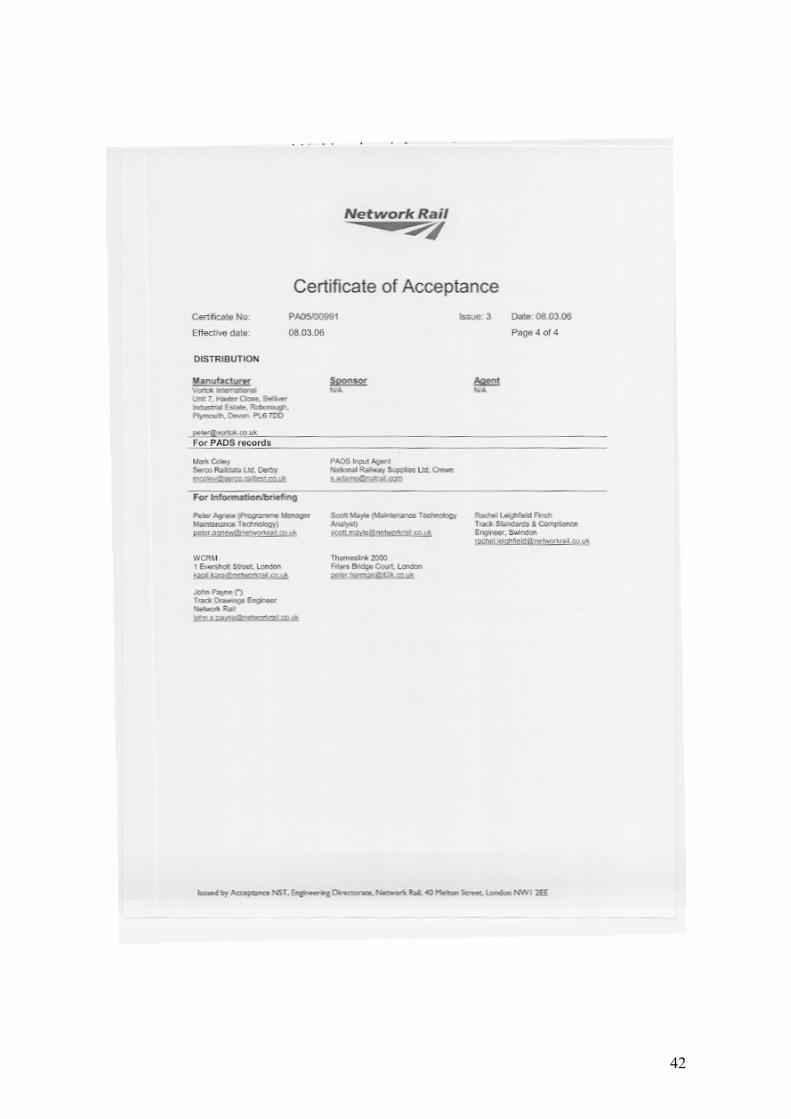
39 – 42 Latest Network Rail Certificate of Acceptance
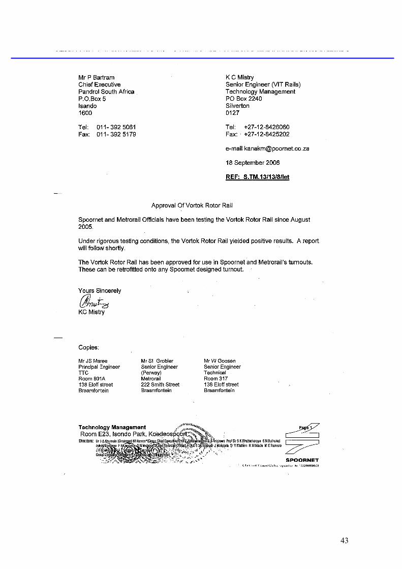
43 Spoornet South Africa 1
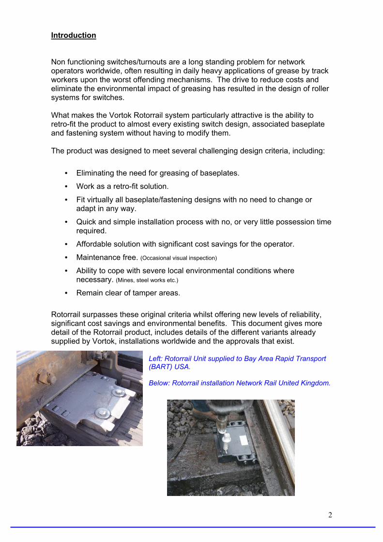
Introduction Non functioning switches/turnouts are a long standing problem for network operators worldwide, often resulting in daily heavy applications of grease by track workers upon the worst offending mechanisms. The drive to reduce costs and eliminate the environmental impact of greasing has resulted in the design of roller systems for switches. What makes the Vortok Rotorrail system particularly attractive is the ability to retro-fit the product to almost every existing switch design, associated baseplate and fastening system without having to modify them. The product was designed to meet several challenging design criteria, including:
• Eliminating the need for greasing of baseplates.
• Work as a retro-fit solution.
• Fit virtually all baseplate/fastening designs with no need to change or adapt in any way.
• Quick and simple installation process with no, or very little possession time required.
• Affordable solution with significant cost savings for the operator.
• Maintenance free. (Occasional visual inspection)
• Ability to cope with severe local environmental conditions where necessary. (Mines, steel works etc.)
• Remain clear of tamper areas. Rotorrail surpasses these original criteria whilst offering new levels of reliability, significant cost savings and environmental benefits. This document gives more detail of the Rotorrail product, includes details of the different variants already supplied by Vortok, installations worldwide and the approvals that exist.
Left: Rotorrail Unit supplied to Bay Area Rapid Transport (BART) USA. Below: Rotorrail installation Network Rail United Kingdom.
2

Concept and Method of Operation The principle of the Rotorrail is very simple, to reduce friction to such an extent that the switch operates reliably without the need for heavy, or indeed any, greasing. The Rotorrail system uses rollers cantilevered over the side of the baseplate structure. The switching blade only takes the mass of the traffic when it is touching the running or stock rail. In this position, the foot of the switch blade is touching, and transfers the wheel load to, the original chair surface. When one side of the switch is closed the matching switch blade is open and takes no wheel load. The Rotorrail unit is positioned so that the first roller is just touching the foot of the switch blade in the closed position and thus the unit is not taking any load.
Rotorrail unit shown in this “ready” mode with the switch blade in the closed position. When the switch is operated the closed blade moves away from the stock rail and immediately rides up onto the first roller. The roller is designed to lift the switch blade, typically by 4mm, and as soon as the switch
blade is lifted most of the drag / friction associated with greased systems disappears. The actuation mechanism only has to act against the rolling resistance and any flexure of the switch blade. Rotorrail unit shown in the “actuated” mode with the switchblade in the open position. The switch blade is now free to travel to its fully open position. The opposite matching blade will of course now move from the open position, supported initially on the Rotor Rail, to the closed position, where it drops off the roller onto the chair surface ready to take traffic load. The Structure of the Rotorrail takes support from the baseplate and uses the existing fixings. By using the existing fixings and being designed around the existing baseplate structure the Rotorrail can be installed very quickly, each unit taking less than 5 minutes to install. 3
Main Features. The unique method of positioning the rollers cantilevered over the side of
the baseplate structure, taking support from it, enables the system to be easily designed/adapted for virtually all baseplate designs.
The above also allows a rail network to rapidly install on both new and
importantly retro fit to existing turnouts without changes to baseplate or fastenings at all.
Maintenance free with no greasing required. The specially hardened type
sealed rollers are lubricated and sealed for life, therefore offering immediate labour savings by eliminating the need to grease.
No adjustments. The units require no vertical adjustment as they work on
a fixed height lift and therefore cannot be incorrectly set by track workers. The system will fit onto, and use, the existing baseplate screws, no special
fixings required at all. Vastly improved reliability of switch performance and reduction in the wear
and tear. Potential energy savings as motor power can be turned down and motor
life extended. Simple installation. Whether fitting to new turnouts or existing systems in
track the installation process takes no more than 10 minutes per unit requiring no possession of the line.
Not prone in any way to damage from tamping machines.
Ability to choose problem baseplates where it is obvious the rail is in heavy
contact with the riser plate and prone to sticking. In the unlikely event of damage or failure the units can be replaced within
minutes.
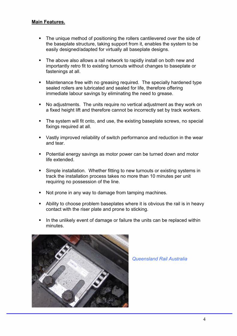
Queensland Rail Australia
4
Business Case The Vortok Rotorrails have an initial purchase cost and an associated installation cost, the latter being particularly small due to the quick installation time. Once installed, they are maintenance free, and therefore free from ongoing costs*. Rotorrails are designed to remove problems, and therefore costs, from the operators network:
Grease Application Costs. This is often a daily occurrence requiring teams of track workers spending many hours a week greasing the baseplates.
Grease Removal/Cleaning Costs. Grease attracts dirt, which in turn renders the grease that builds up on the baseplate useless by forming a hardened paste. This requires cleaning before being re-greased.
Switch Failure Cost. What is the cost to the operator of traffic that has to be stopped until the switch is loosened?
The above are immediate cost savings upon installation, however it is also worth bearing in mind that additional ongoing hidden savings will benefit the operator.
Power Savings. The actuation motors can be turned down to save power as the switchblades will require less force to move them.
Extended Motor Life. This reduction to the level power required by the motor to move the switchblade should extend its working life.
Reduction to Wear and Tear. The wear and tear to the switch is reduced dramatically as the switchblade now has a much smoother movement.
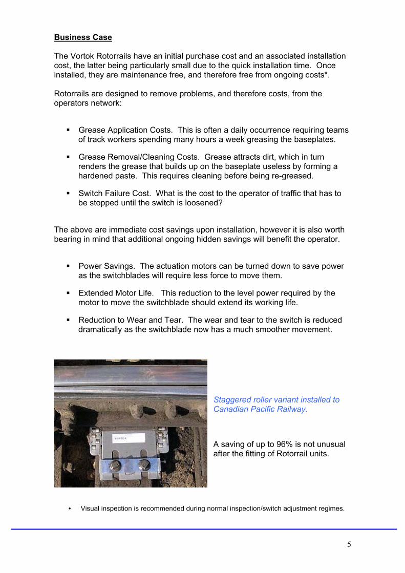
Staggered roller variant installed to Canadian Pacific Railway.
A saving of up to 96% is not unusual after the fitting of Rotorrail units.
• Visual inspection is recommended during normal inspection/switch adjustment regimes.
5

Approvals. Rotorrails were originally designed by Mazzi Technology S.R.I. in Italy. Vortok International now design and manufacture Rotorrail units under licence for the global market outside of Italy and Spain. The original homologation for Rotorrail came from FS in Italy in 1999 after extensive trials. Italy now has several thousand units in operation with a sub 1% failure rate. Vortok first began the design and development of Rotorrails to the in 2000. The trials in the UK were undertaken by Railtrack, now Network Rail, and full product acceptance after successful trials was granted in 2003. There are over 1,700 Rotorrails in operation in the UK and the performance has been so successful that an additional acceptance certificate has been awarded for different variants in 2006. Copies of the latest approval certificates etc are to be found in the appendix, including; RFI Italy, EBA Germany and Network Rail in the UK. Since the awards were made in Italy and the UK thousands of Rotorrail units have been manufactured and successfully installed worldwide, including: Germany USA Canada Ireland Sweden Denmark Portugal Finland South Africa Australia Italy and Spain (Mazzi Technology)
Examples of trials are contained in the appendix, and currently extended trials are being undertaken in: France Germany - Private networks such as mining and power Morocco Norway USA Malaysia
6
China
Installation. As mentioned the Rotorrail units are ideally suited for retro-fitting to existing turnouts. The process is simple, takes just a few minutes per unit and can often
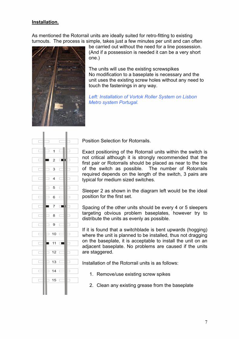
be carried out without the need for a line possession. (And if a possession is needed it can be a very short one.) The units will use the existing screwspikes No modification to a baseplate is necessary and the unit uses the existing screw holes without any need to touch the fastenings in any way. Left: Installation of Vortok Roller System on Lisbon Metro system Portugal.
Position Selection for Rotorrails. Exact positioning of the Rotorrail units within the switch is not critical although it is strongly recommended that the first pair or Rotorrails should be placed as near to the toe of the switch as possible. The number of Rotorrails required depends on the length of the switch, 3 pairs are typical for medium sized switches. Sleeper 2 as shown in the diagram left would be the ideal position for the first set. Spacing of the other units should be every 4 or 5 sleepers targeting obvious problem baseplates, however try to distribute the units as evenly as possible. If it is found that a switchblade is bent upwards (hogging) where the unit is planned to be installed, thus not dragging on the baseplate, it is acceptable to install the unit on an adjacent baseplate. No problems are caused if the units are staggered. Installation of the Rotorrail units is as follows:
1. Remove/use existing screw spikes
2. Clean any existing grease from the baseplate
2
3
4
5
6
7
8
9
10
11
12
13
14
15
7
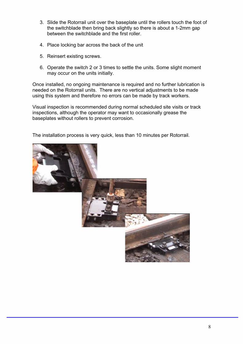
3. Slide the Rotorrail unit over the baseplate until the rollers touch the foot of the switchblade then bring back slightly so there is about a 1-2mm gap between the switchblade and the first roller.
4. Place locking bar across the back of the unit 5. Reinsert existing screws.
6. Operate the switch 2 or 3 times to settle the units. Some slight moment
may occur on the units initially. Once installed, no ongoing maintenance is required and no further lubrication is needed on the Rotorrail units. There are no vertical adjustments to be made using this system and therefore no errors can be made by track workers. Visual inspection is recommended during normal scheduled site visits or track inspections, although the operator may want to occasionally grease the baseplates without rollers to prevent corrosion. The installation process is very quick, less than 10 minutes per Rotorrail.
8
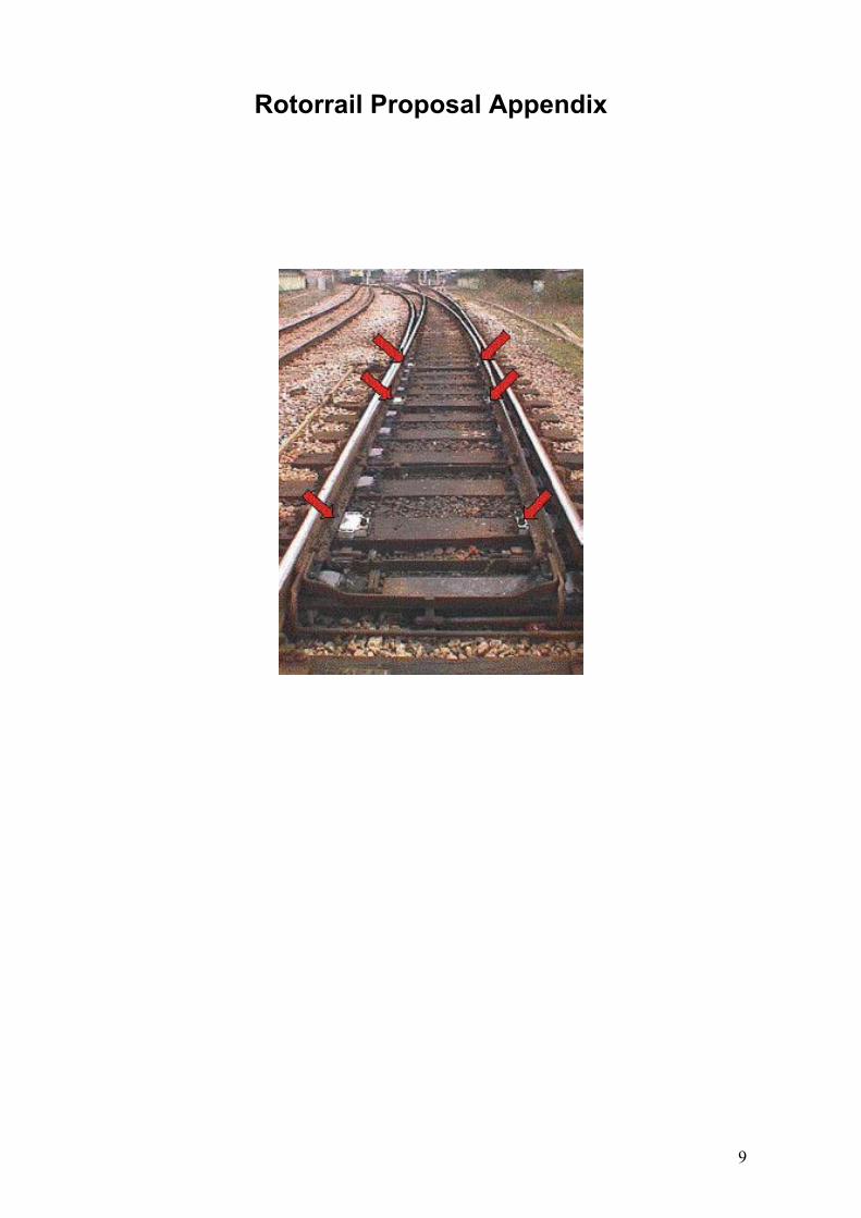
Rotorrail Proposal Appendix
9

Material Specifications The Rotorrail units are manufactured from stainless steel grade 316 as this grade offers good anti-corrosive properties and strength. Some discolouration may occur from contact with the baseplate but this is not corrosion. The rollers themselves are manufactured from case hardened steel, rotating on hardened steel shafts and are sealed for life. (080A15 Grade) Where the Rotorrails are to be used in an excessively corrosive environment such as areas with high levels of coal dust, the 440C stainless steel grade is used to manufacture the rollers as this has better anti-corrosion properties. 316 Grade Stainless Steel used for the main body of Rotorrail units. (Industry standard grade description.*) 316 grade stainless steel is the standard is the standard molybdenum-bearing grade, second in importance to 304 amongst the austenitic stainless steels. The molybdenum-bearing gives 316 grade better overall corrosion resistant properties than 304, particularly higher resistance to pitting and corrosion in chloride environments. This steel has excellent forming and welding characteristics. It is readily brake or roll formed into a variety of parts for applications in the industrial, architectural and transportation fields. It also has outstanding welding characteristics. 440C Stainless Steel used as the alternative to Case Hardened Steel when used in corrosive environments. (Industry standard grade description.*) In the hardened condition this material has a Martensite + Carbide structure. It is capable of attaining, after heat treatment, the highest strength, hardness (51 – 61 Rc) and wear resistance of all the stainless steel alloys. Its very high carbon content is responsible for these characteristics and the 440C grade is particularly suited to applications such as ball bearings, valve parts and of course rollers. The stainless steel is optimised for high hardness, it has good resistance to the atmosphere, fresh water, food stuffs, alkalines and acids. The corrosive resistance of grade 440C approximately matches that of grade 304 in many environments. 440C stainless steel is used in a wide variety of industries including bearing manufacture, aerospace applications, surgical instruments etc. Vortok are happy to advise as to the best material to use for the roller if uncertain.
*Source: Azom.com
10
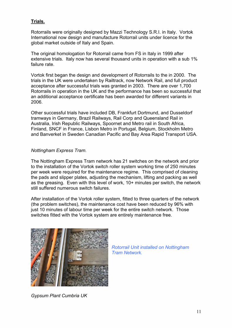
Trials. Rotorrails were originally designed by Mazzi Technology S.R.I. in Italy. Vortok International now design and manufacture Rotorrail units under licence for the global market outside of Italy and Spain. The original homologation for Rotorrail came from FS in Italy in 1999 after extensive trials. Italy now has several thousand units in operation with a sub 1% failure rate. Vortok first began the design and development of Rotorrails to the in 2000. The trials in the UK were undertaken by Railtrack, now Network Rail, and full product acceptance after successful trials was granted in 2003. There are over 1,700 Rotorrails in operation in the UK and the performance has been so successful that an additional acceptance certificate has been awarded for different variants in 2006. Other successful trials have included DB, Frankfurt Dortmund, and Dusseldorf tramways in Germany, Brazil Railways, Rail Corp and Queensland Rail in Australia, Irish Republic Railways, Spoornet and Metro rail in South Africa, Finland, SNCF in France, Lisbon Metro in Portugal, Belgium, Stockholm Metro and Banverket in Sweden Canadian Pacific and Bay Area Rapid Transport USA. Nottingham Express Tram. The Nottingham Express Tram network has 21 switches on the network and prior to the installation of the Vortok switch roller system working time of 250 minutes per week were required for the maintenance regime. This comprised of cleaning the pads and slipper plates, adjusting the mechanism, lifting and packing as well as the greasing. Even with this level of work, 10+ minutes per switch, the network still suffered numerous switch failures. After installation of the Vortok roller system, fitted to three quarters of the network (the problem switches), the maintenance cost have been reduced by 96% with just 10 minutes of labour time per week for the entire switch network. Those switches fitted with the Vortok system are entirely maintenance free.
Rotorrail Unit installed on Nottingham Tram Network.
Gypsum Plant Cumbria UK
11
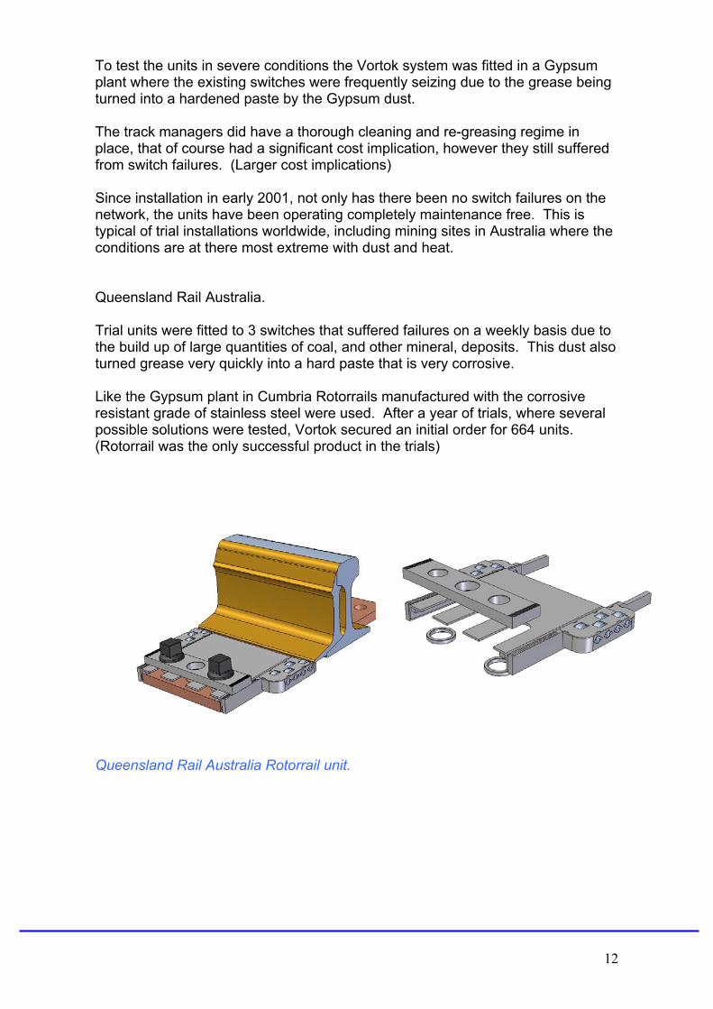
To test the units in severe conditions the Vortok system was fitted in a Gypsum plant where the existing switches were frequently seizing due to the grease being turned into a hardened paste by the Gypsum dust. The track managers did have a thorough cleaning and re-greasing regime in place, that of course had a significant cost implication, however they still suffered from switch failures. (Larger cost implications) Since installation in early 2001, not only has there been no switch failures on the network, the units have been operating completely maintenance free. This is typical of trial installations worldwide, including mining sites in Australia where the conditions are at there most extreme with dust and heat. Queensland Rail Australia. Trial units were fitted to 3 switches that suffered failures on a weekly basis due to the build up of large quantities of coal, and other mineral, deposits. This dust also turned grease very quickly into a hard paste that is very corrosive. Like the Gypsum plant in Cumbria Rotorrails manufactured with the corrosive resistant grade of stainless steel were used. After a year of trials, where several possible solutions were tested, Vortok secured an initial order for 664 units. (Rotorrail was the only successful product in the trials)
Queensland Rail Australia Rotorrail unit.
12
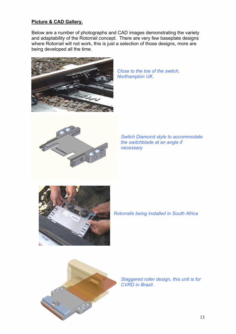
Picture & CAD Gallery. Below are a number of photographs and CAD images demonstrating the variety and adaptability of the Rotorrail concept. There are very few baseplate designs where Rotorrail will not work, this is just a selection of those designs, more are being developed all the time.
Close to the toe of the switch, Northampton UK.
Switch Diamond style to accommodate the switchblade at an angle if necessary
Rotorrails being installed in South Africa
Staggered roller design, this unit is for CVRD in Brazil.
13
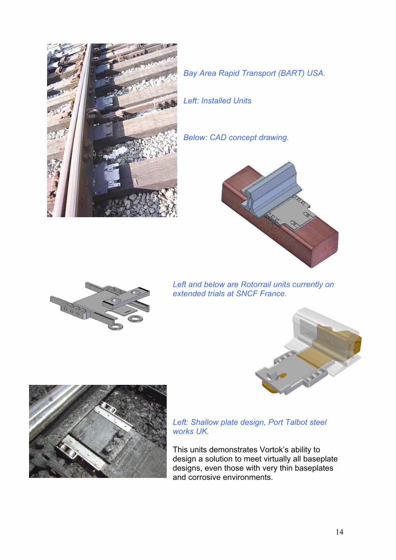
Bay Area Rapid Transport (BART) USA. Left: Installed Units Below: CAD concept drawing.
Left and below are Rotorrail units currently on extended trials at SNCF France.
Left: Shallow plate design, Port Talbot steel works UK. This units demonstrates Vortok’s ability to design a solution to meet virtually all baseplate designs, even those with very thin baseplates and corrosive environments.
14
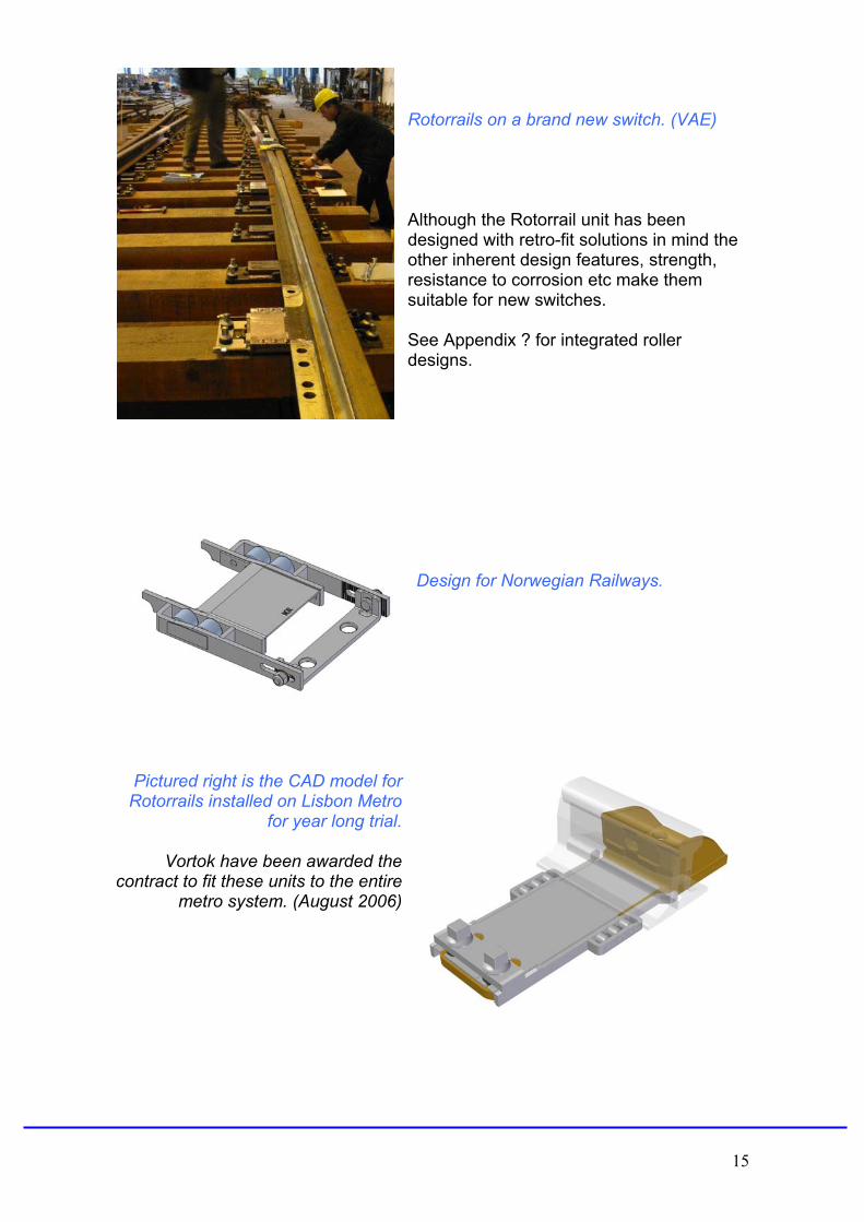
Rotorrails on a brand new switch. (VAE) Although the Rotorrail unit has been designed with retro-fit solutions in mind the other inherent design features, strength, resistance to corrosion etc make them suitable for new switches. See Appendix ? for integrated roller designs.
Design for Norwegian Railways.
Pictured right is the CAD model for Rotorrails installed on Lisbon Metro
for year long trial.
Vortok have been awarded the contract to fit these units to the entire
metro system. (August 2006)
15
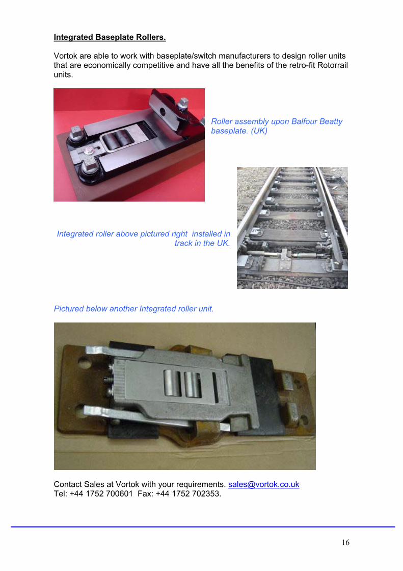
Integrated Baseplate Rollers. Vortok are able to work with baseplate/switch manufacturers to design roller units that are economically competitive and have all the benefits of the retro-fit Rotorrail units.
Roller assembly upon Balfour Beatty baseplate. (UK)
Integrated roller above pictured right installed in
track in the UK. Pictured below another Integrated roller unit.
Contact Sales at Vortok with your requirements. [email protected] Tel: +44 1752 700601 Fax: +44 1752 702353.
16
ISO Accreditation, Approvals and Test Reports
17
18
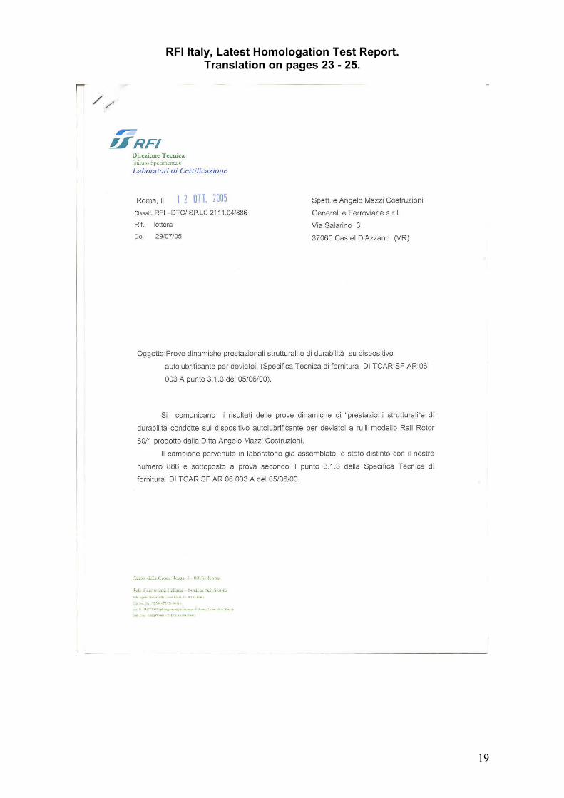
RFI Italy, Latest Homologation Test Report. Translation on pages 23 - 25.
19
20
21
22
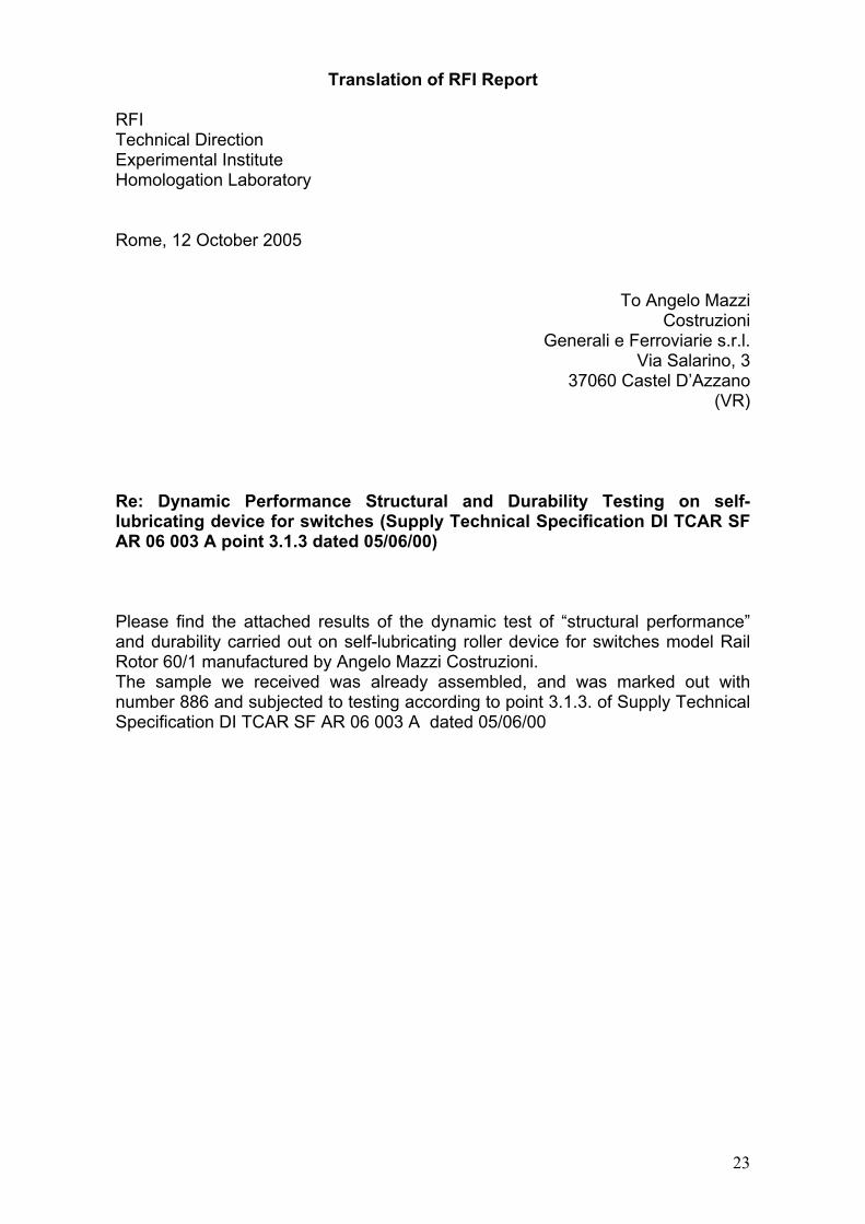
Translation of RFI Report RFI Technical Direction Experimental Institute Homologation Laboratory Rome, 12 October 2005
To Angelo Mazzi
Costruzioni Generali e Ferroviarie s.r.l.
Via Salarino, 3 37060 Castel D’Azzano
(VR) Re: Dynamic Performance Structural and Durability Testing on self-lubricating device for switches (Supply Technical Specification DI TCAR SF AR 06 003 A point 3.1.3 dated 05/06/00) Please find the attached results of the dynamic test of “structural performance” and durability carried out on self-lubricating roller device for switches model Rail Rotor 60/1 manufactured by Angelo Mazzi Costruzioni. The sample we received was already assembled, and was marked out with number 886 and subjected to testing according to point 3.1.3. of Supply Technical Specification DI TCAR SF AR 06 003 A dated 05/06/00
23
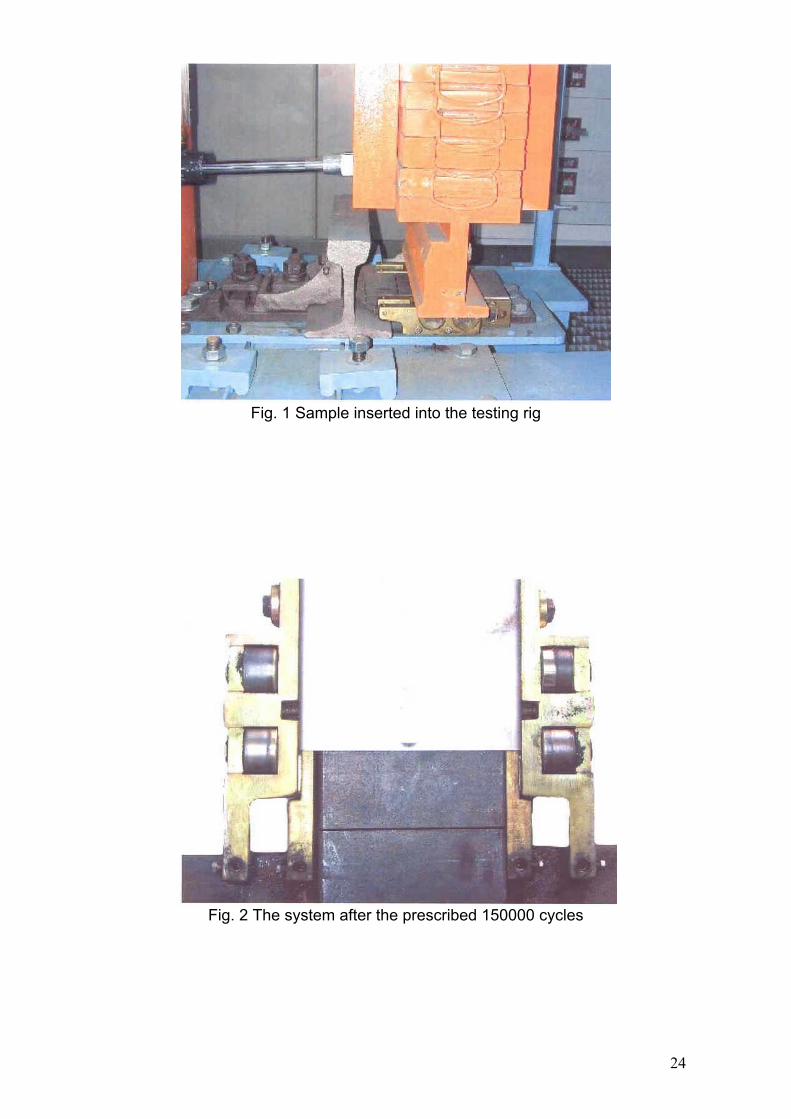
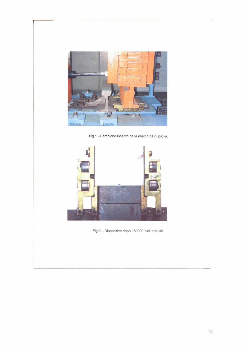
Fig. 1 Sample inserted into the testing rig
Fig. 2 The system after the prescribed 150000 cycles
24
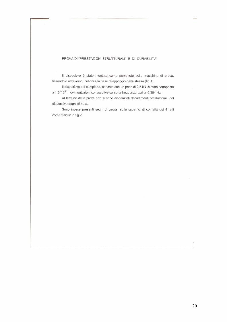
“STRUCTURAL PERFORMANCE” AND DURABILITY TEST The system was mounted as received on the testing machine, and bolted down to the supporting surface (fig. 1). The sample device, loaded with a weight of 2.5 kN, was subjected to 1.5*105 cycles, with a frequency of 0.384 Hz. At the end the test, no significant performance decay of the system was noticed. On the contrary, there are some wear signs on the surface contacting the four rollers as shown in Fig. 2. CONCLUSIONS The tested sample, subjected to the dynamic cycles prescribed by Supply Technical Specification DI TCAR SF AR 06 003 A point 3.1.3 dated 05/06/00, successfully passed the test.
Lab Technician Head of the Homologation Laboratory Campanari Florio Ing. Giovanni
25
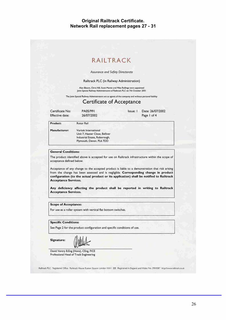
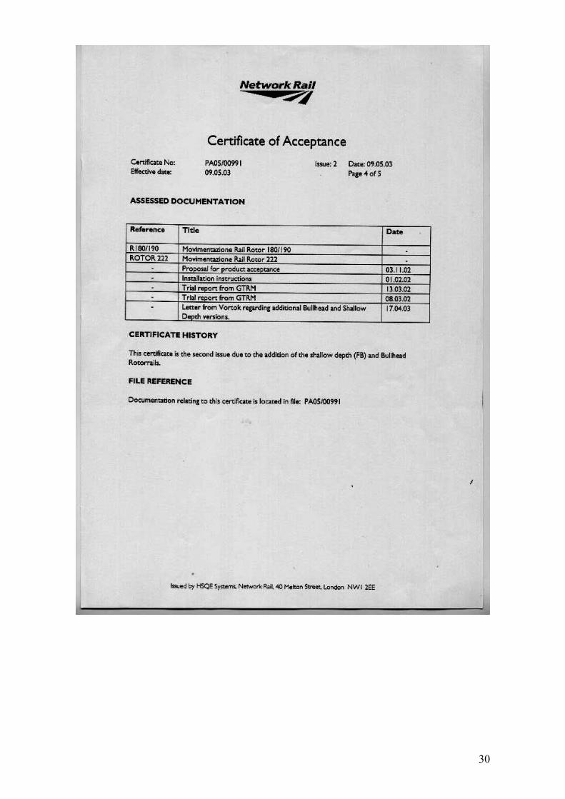
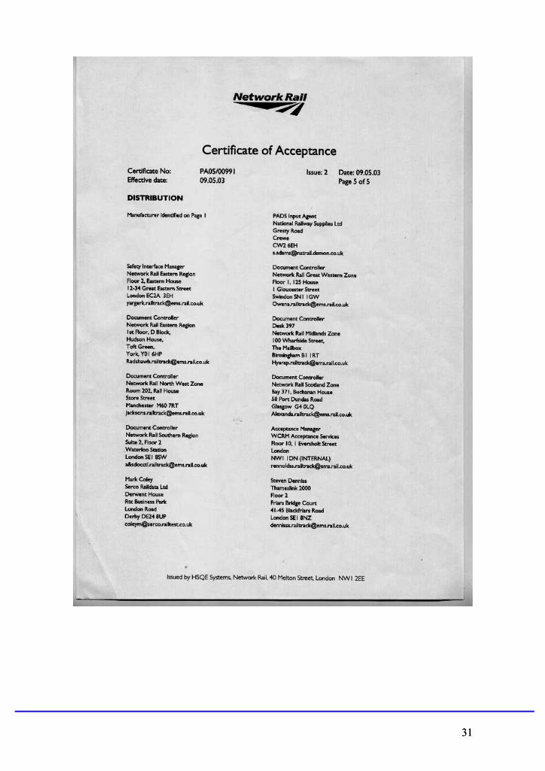
Original Railtrack Certificate. Network Rail replacement pages 27 - 31
26
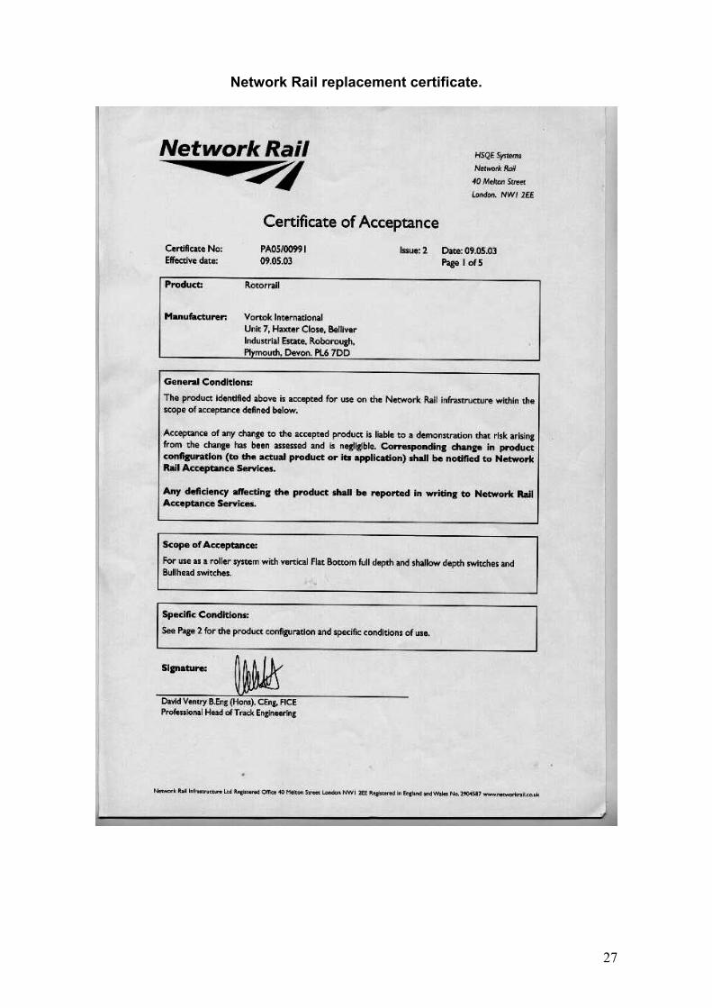
Network Rail replacement certificate.
27
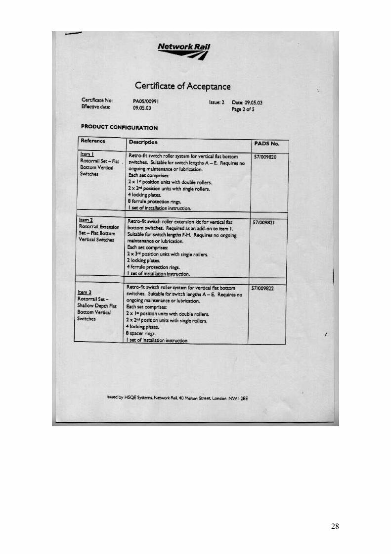
28
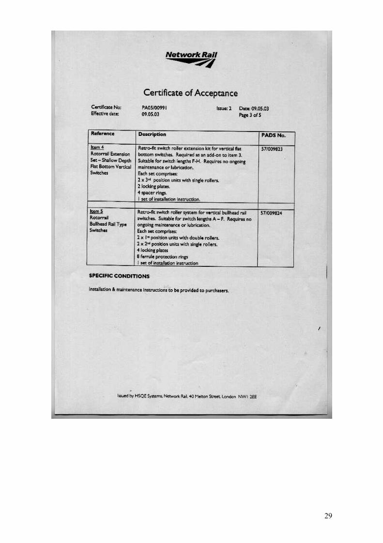
29
30
31 31
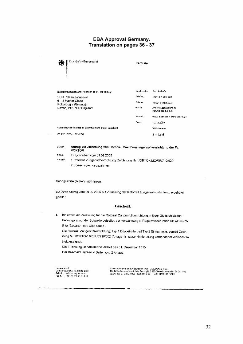
EBA Approval Germany. Translation on pages 36 - 37
32
33

34
35

Translation of EBA’s letter 15.12.2005 Application for Homologation of Rotorrail Switch Tongue Rollers of VORTOK Your letter dated 09.09.2005. Attachments: 1 Rotorrail Switch Tongue Roller Drawing No. Vortok MC/RR/710/002 2 Compliance Signs Dear Sir or Madam, With reference to your application of 09.09.2005 we hereby give you our CONFIRMATION
1. I grant the permission for the Rotorrail Switch Tongue Roller System, affixed to the slide plate and its fastenings , to be used in standard switches acc. To DB regulations „constructions for the permanent way“. The Rotorrail Switch Tongue Roller System, Type 1 double rollers and type 2 single roller, acc. To drawing No. VORTOK MC/RR/710/002 (attachment 1) is suitable for retrofitting existing switches in track.
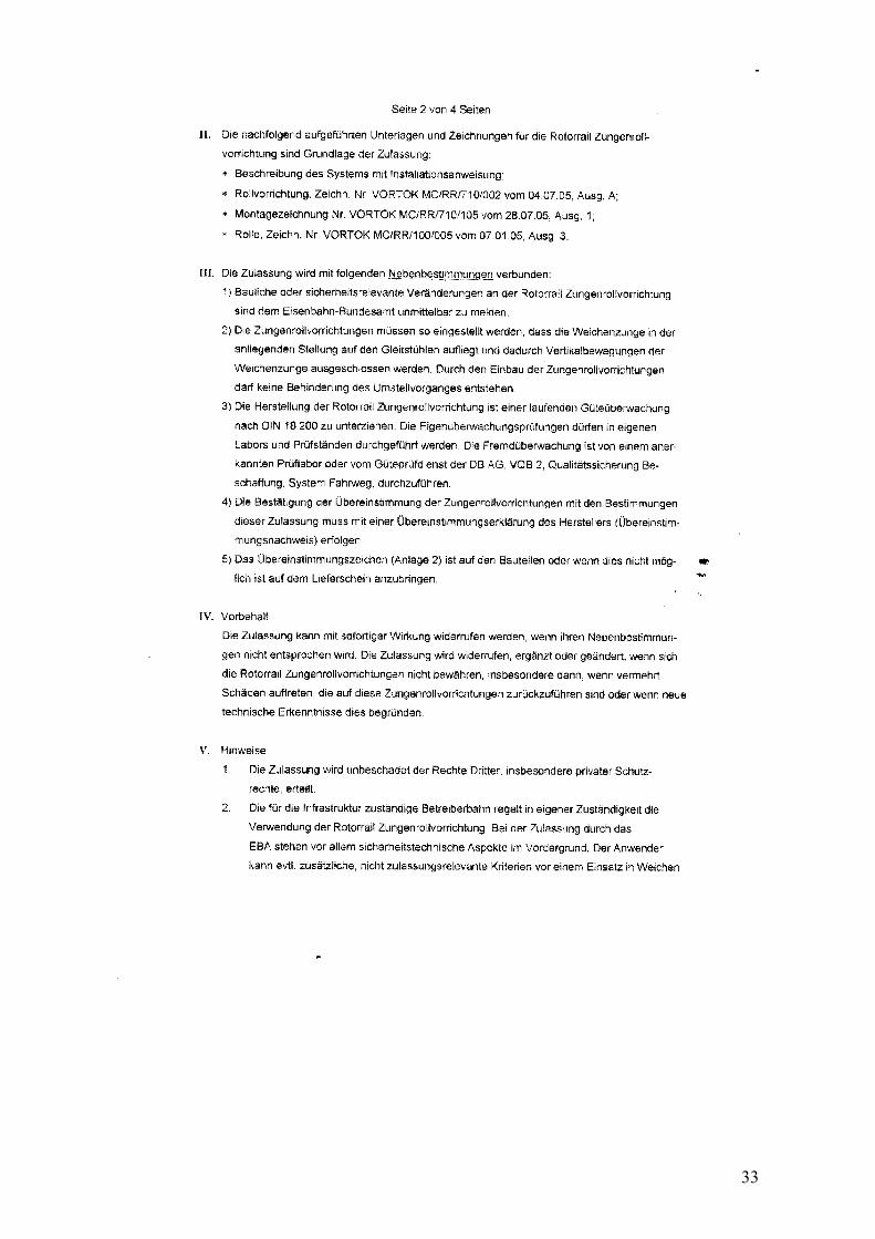
The permission is limited to 31.12.2010. This permission comprises 2 pages and 2 attachments. II. the following supplements and drawings are the basis of our permission:
• Description of the system plus instructions for installation • Roller system, drawing no. VORTOK MC/RR/710/002 of 04.07.05, edition
A • Installation drawing No. VORTOK MC/RR/710/105 of 28.07.05, edition 1 • Roller, drawing No. VORTOK MC/RR/100/005 of 07.01.05, edition 3
III. the permission is valid in combination with the following sub-regulations:
• Any changes to the construction or security-relevant changes to the Rotorrail Switch tongue roller system must be communicated to EBA without any delay
• The switch tongue roller systems have to be adjusted such that the rail tongue when attached to the stock rail must rest on the base plate and thus no vertical movement of the tongue is prevented. By installing the roller system there must be no impediment in moving the tongue.
• Manufacture of the Rotorrail system is subject to a permanent quality control acc. To DIN 18200. Self monitoring may be done by internal laboratory and testing arrays. External monitoring has to be done by an approved laboratory or by quality control service of DB AG, VQB 2, Quality Control Procurement, System Track.
• Confirmation of conformity of switch tongue rollers with the regulations of this approval must be done by means of a Declaration of Conformity of manufacturer.
• The Sign (attachment 2) has to be affixed to the parts or, if not possible, must be attached to the delivery note.
IV. Reservation The approval may be revoked with immediate effect if the sub-regulations are not complied with. The approval will be revoked, supplemented or modified if the
36
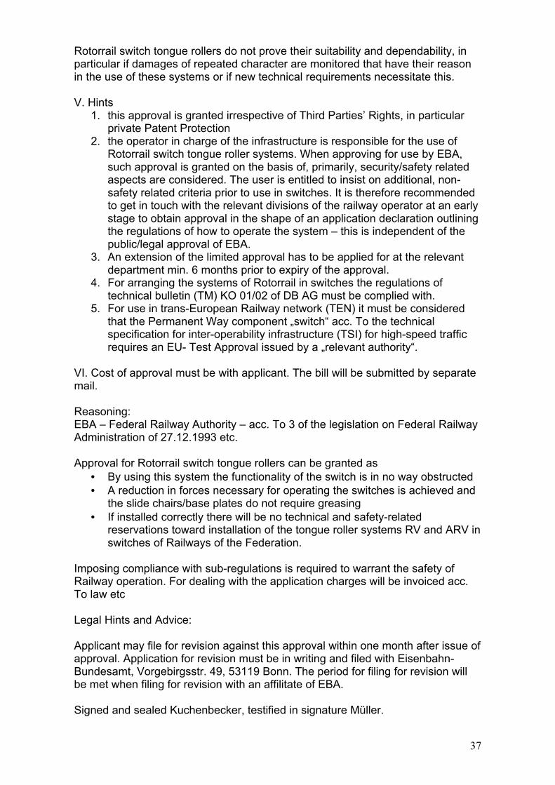
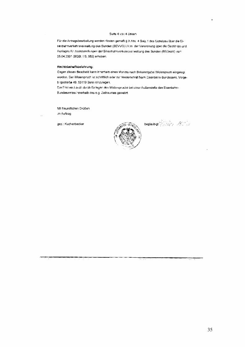
Rotorrail switch tongue rollers do not prove their suitability and dependability, in particular if damages of repeated character are monitored that have their reason in the use of these systems or if new technical requirements necessitate this. V. Hints
1. this approval is granted irrespective of Third Parties’ Rights, in particular private Patent Protection
2. the operator in charge of the infrastructure is responsible for the use of Rotorrail switch tongue roller systems. When approving for use by EBA, such approval is granted on the basis of, primarily, security/safety related aspects are considered. The user is entitled to insist on additional, non-safety related criteria prior to use in switches. It is therefore recommended to get in touch with the relevant divisions of the railway operator at an early stage to obtain approval in the shape of an application declaration outlining the regulations of how to operate the system – this is independent of the public/legal approval of EBA.
3. An extension of the limited approval has to be applied for at the relevant department min. 6 months prior to expiry of the approval.
4. For arranging the systems of Rotorrail in switches the regulations of technical bulletin (TM) KO 01/02 of DB AG must be complied with.
5. For use in trans-European Railway network (TEN) it must be considered that the Permanent Way component „switch“ acc. To the technical specification for inter-operability infrastructure (TSI) for high-speed traffic requires an EU- Test Approval issued by a „relevant authority“.
VI. Cost of approval must be with applicant. The bill will be submitted by separate mail. Reasoning: EBA – Federal Railway Authority – acc. To 3 of the legislation on Federal Railway Administration of 27.12.1993 etc. Approval for Rotorrail switch tongue rollers can be granted as
• By using this system the functionality of the switch is in no way obstructed • A reduction in forces necessary for operating the switches is achieved and
the slide chairs/base plates do not require greasing • If installed correctly there will be no technical and safety-related
reservations toward installation of the tongue roller systems RV and ARV in switches of Railways of the Federation.
Imposing compliance with sub-regulations is required to warrant the safety of Railway operation. For dealing with the application charges will be invoiced acc. To law etc Legal Hints and Advice: Applicant may file for revision against this approval within one month after issue of approval. Application for revision must be in writing and filed with Eisenbahn-Bundesamt, Vorgebirgsstr. 49, 53119 Bonn. The period for filing for revision will be met when filing for revision with an affilitate of EBA. Signed and sealed Kuchenbecker, testified in signature Müller.
37
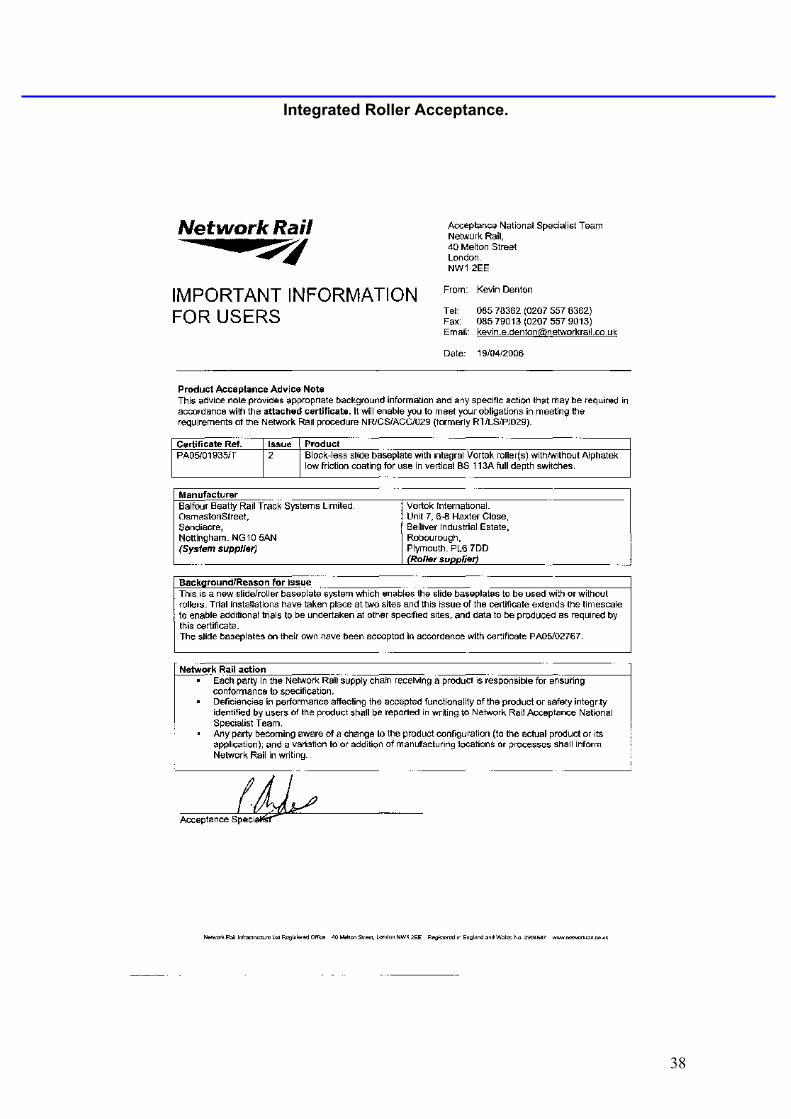
Integrated Roller Acceptance.
38
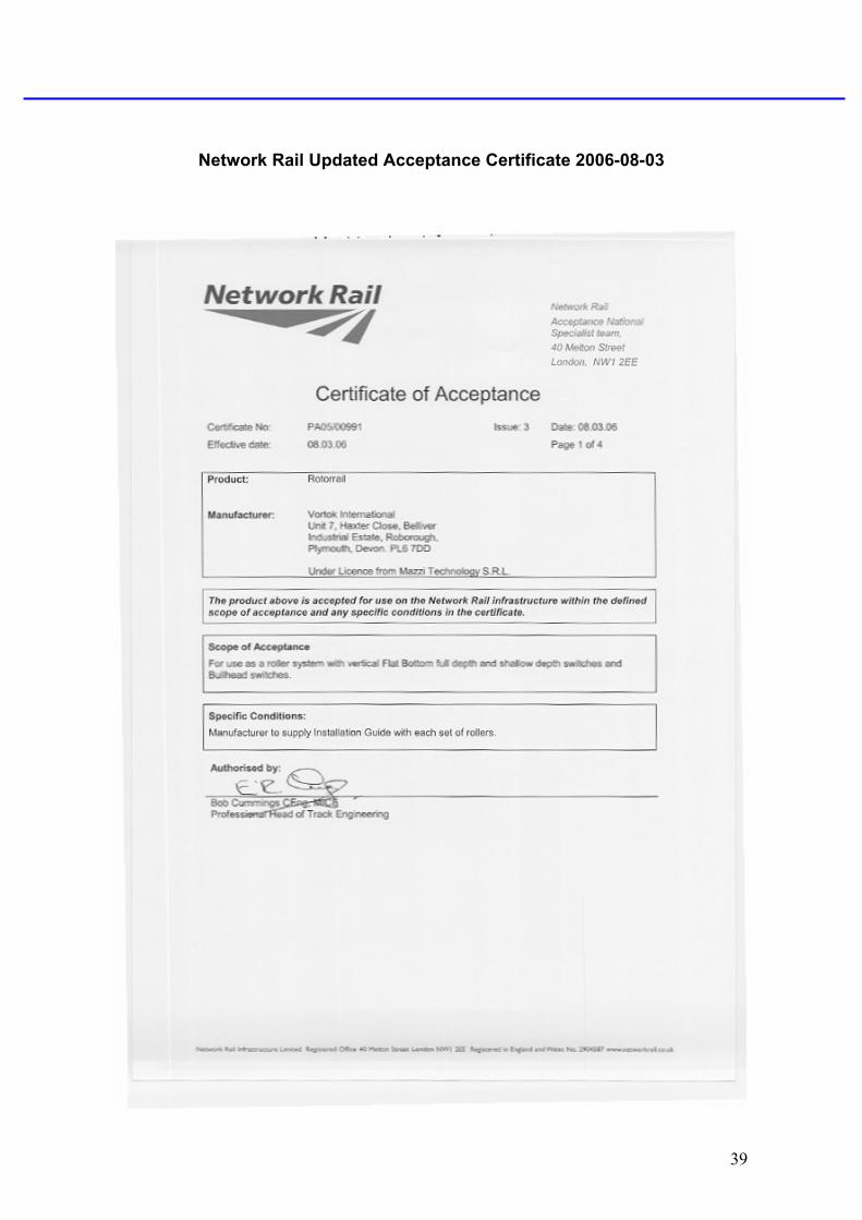
Network Rail Updated Acceptance Certificate 2006-08-03
39
40
41
42
43


![VORTOK INTERNATIONAL - Rail Signalling Products Profile Brochure_AW[1].pdf · (Train Protection & Warning System) in the UK, the Balise Mount System ... for use in 3rd rail areas](https://img.pdfslide.us/doc/110x75/5ab048937f8b9a5d0a8e9380/vortok-international-rail-signalling-profile-brochureaw1pdftrain-protection.jpg)