Embed Size (px)
Citation preview
172-65410MA-02 (EF73 Vortex Flowmeter) 26 May 2011
Vortex Flowmeter EF73
Copyright © 2009 by TLV CO., LTD. All rights reserved
Rev 2-2009
ISO 9001/ ISO 14001
Kakogawa, Japan is approved by LRQA LTD. to ISO 9001/14001
172-65410MA-02 EF73 Vortex Flowmeter
2
Contents
Contents.............................................................................................................. 2
1 Safety Instructions........................................................................................ 4 1.1 Correct Usage ........................................................................................................4 1.2 Dangers and Notes ................................................................................................4 1.3 Operational Safety .................................................................................................4 1.4 Installation, Commissioning and Operation............................................................5 1.5 Repairs, Dangerous Chemicals .............................................................................5 1.6 Technical Improvements ........................................................................................5
2 System Description ...................................................................................... 6 2.1 EF73 Measuring System........................................................................................6
3 Mounting and Installation............................................................................. 7 3.1 Transport................................................................................................................7 3.2 Degree of Protection ..............................................................................................7 3.3 Installation Conditions ............................................................................................8
3.3.1 Inlet and Outlet Sections .............................................................................. 8 3.3.2 Installation Orientation................................................................................ 10 3.3.3 Pipeline Heat Insulation.............................................................................. 11 3.3.4 Minimum Maintenance Space .................................................................... 11 3.3.5 Other Considerations ................................................................................. 12
3.4 Mounting the Flowmeter.......................................................................................13 3.5 Mounting the Transmitter (Remote Version) ........................................................14 3.6 Electronics Housing / Display (Mounting/Rotating) ..............................................15
4 Electrical Connection ................................................................................. 16 4.1 Connecting the Transmitter..................................................................................16 4.2 Wiring Diagrams...................................................................................................17 4.3 Connecting the Remote Version ..........................................................................18
5 Operation..................................................................................................... 19 5.1 Display and Operating Elements..........................................................................19 5.2 Select Functions and Change Parameters ..........................................................20
6 Technical Data............................................................................................. 21 6.1 Technical Data at a Glance..................................................................................21
6.1.1 Application.................................................................................................. 21 6.1.2 Function and System Design ..................................................................... 21 6.1.3 Input ........................................................................................................... 21 6.1.4 Output......................................................................................................... 22 6.1.5 Power Supply ............................................................................................. 23 6.1.6 Performance Characteristics ...................................................................... 23 6.1.7 Mechanical Construction ............................................................................ 26 6.1.8 Human Interface......................................................................................... 26
6.2 Remote Transmitter Dimensions..........................................................................26 6.3 EF73 Dimensions – Flangeless Connection ........................................................27 6.4 EF73 Dimensions – Flanged Connection.............................................................28 6.5 Dimensions of Flow Conditioner (optional) ..........................................................30
7 Commissioning ........................................................................................... 32 7.1 Function Check ....................................................................................................32 7.2 Commissioning.....................................................................................................32
7.2.1 Switching on the Measuring Device ........................................................... 32
EF73 Vortex Flowmeter 172-65410MA-02
3
7.2.2 “Commissioning” Quick Setup .................................................................... 32
8 Device Functions ........................................................................................ 35 8.1 Function Matrix .................................................................................................... 35 8.2 Descriptions of Functions .................................................................................... 36
8.2.1 Group MEASURED VALUES ..................................................................... 36 8.2.2 Group SYSTEM UNITS .............................................................................. 39 8.2.3 Group QUICK SETUP ................................................................................ 42 8.2.4 Group OPERATION ................................................................................... 43 8.2.5 Group USER INTERFACE ......................................................................... 44 8.2.6 Group TOTALIZERS 1 and 2 ..................................................................... 48 8.2.7 Group HANDLING TOTALIZERS............................................................... 50 8.2.8 Group CURRENT OUTPUT ....................................................................... 50 8.2.9 Group FREQUENCY (PULSE) OUTPUT ................................................... 53 8.2.10 Information on the Response of the Status Output................................... 66 8.2.11 Group HANDLING COMMUNICATION.................................................... 67 8.2.12 Group PROCESS PARAMETER.............................................................. 69 8.2.13 Group FLOW COMPUTER....................................................................... 71 8.2.14 Sample values for the functions: TEMPERATURE VALUE, DENSITY
VALUE and EXPANSION COEFFICIENT................................................ 78 8.2.15 Group SYSTEM PARAMETER................................................................. 79 8.2.16 Group SENSOR DATA............................................................................. 80 8.2.17 Group SUPERVISION .............................................................................. 82 8.2.18 Group SIMULATION................................................................................. 84 8.2.19 Group SENSOR VERSION ...................................................................... 85 8.2.20 Group AMPLIFIER VERSION................................................................... 85 8.2.21 Group ADVANCED DIAGNOSIS (optional).............................................. 85
9 Installing and Removing Electronics Boards ........................................... 90
10 Error Message Display ................................................................................ 92
11 Troubleshooting .......................................................................................... 93 11.1 Troubleshooting Instructions ............................................................................. 93 11.2 System Error Messages .................................................................................... 94 11.3 Process Error Messages ................................................................................... 98 11.4 Process Errors Without Messages .................................................................... 98 11.5 Response of Outputs to Errors........................................................................ 100
12 Factory Settings ........................................................................................ 101
13 Flow Rate Data........................................................................................... 102 13.1 Flow Rate for Saturated Steam ....................................................................... 102 13.2 Flow Rate for Air or Water ............................................................................... 103
14 Product Warranty....................................................................................... 104
15 Service........................................................................................................ 105
172-65410MA-02 EF73 Vortex Flowmeter
4
1 Safety Instructions
1.1 Correct Usage
• EF73 measuring system is used to measure the flow of saturated steam, superheated steam, air and water. Do not use to measure the flow of toxic, flammable or otherwise hazardous fluids. Use this system only as intended.
• The primarily measured variables are volume flow and temperature. From these values, the device can use stored data on density and enthalpy to calculate and output information such as mass flow and heat flow.
• The manufacturer assumes no liability for damage or other accidents caused by incorrect use of the instrument.
1.2 Dangers and Notes
All instruments are designed to meet state-of-the-art safety requirements, have been tested, and have left the factory in a condition in which they are safe to operate. The devices comply with the applicable standards and regulations in accordance with EN 61010 “Protection Measures for Electrical Equipment for Measurement, Control, Regulation and Laboratory Procedures”. They can, however, be a source of danger if used incorrectly or for anything other than the designated use. Consequently, always pay particular attention to the safety instructions indicated in these Operating Instructions by the following symbols: Warning! “Warning” indicates an action or procedure that, if not performed correctly, can result in injury or a safety hazard. Comply strictly with the instructions and proceed with care. Caution! “Caution” indicates an action or procedure that, if not performed correctly, can result in incorrect operation or destruction of the device. Comply strictly with the instructions. Note! “Note” indicates an action or procedure that, if not performed correctly, can have an indirect effect on operation or trigger an unexpected response on the part of the device.
1.3 Operational Safety
• The EF73 measuring system complies with the general safety requirements in accordance with EN 61010 and the EMC requirements of EN 61326/A1 and NAMUR recommendations NE 21 and NE 43.
• Housing ingress protection IP 67 to EN 60529. • A comprehensive self-monitoring feature of the measuring system ensures
high operational safety. In cases of error, the current output assumes a predefined response, the signal of the pulse output is set to the fall-back value of 0 Hz. The appropriate error messages are shown on the LCD.
• On power failure, the configuration data of the measuring system remain in the EEPROM (without batteries). The totalizer remains on the value last shown.
Note!
Warning!
Caution!
EF73 Vortex Flowmeter 172-65410MA-02
5
1.4 Installation, Commissioning and Operation
• Mounting, electrical installation, commissioning and maintenance of the device must be carried out by trained, qualified specialists authorized to perform such work by the operator of the facility. The specialist must have read and understand this manual before carrying out its instructions.
• The device may only be operated by personnel who are authorized and trained by the operator of the facility. Strict compliance with the instructions in these Operating Instructions is mandatory.
• In the case of special fluids (incl. fluids for cleaning), TLV will be happy to assist in clarifying the material resistance properties of wetted parts. However, the user is responsible for the choice of wetted materials as regards their in-process resistance to corrosion; the manufacturer refuses to accept liability..
• The installer must ensure that the measuring system is correctly wired in accordance with the wiring diagrams.
There is no longer any contact protection once the housing cover is removed.
• Observe all local regulations governing the opening and repair of electrical devices.
1.5 Repairs, Dangerous Chemicals
The following procedures must be carried out before an EF73 is sent to TLV for repair: Note: References to use with hazardous fluids are for customers having
special permission and a signed contract with TLV for hazardous use. • A note must be enclosed with the instrument, containing a description of the
fault, the application and the chemical and physical properties of the fluid being measured.
• Remove all fluid residues that may be present. Pay special attention to the gasket grooves and crevices where fluid may be present. This is especially important if the fluid is dangerous to health, e.g. flammable, toxic, caustic, carcinogenic, etc.
• No instrument should be returned to TLV without all dangerous material being removed first.
Incomplete cleaning of the device may result in waste disposal requirements or cause harm to personnel (burns, etc.). Any costs arising from this will be charged to the operator of the device.
1.6 Technical Improvements
The manufacturer reserves the right to modify technical data without prior notice. Your local TLV Distributor or Sales Office will supply you with all current information and any updates to this manual.
Warning!
172-65410MA-02 EF73 Vortex Flowmeter
6
2 System Description
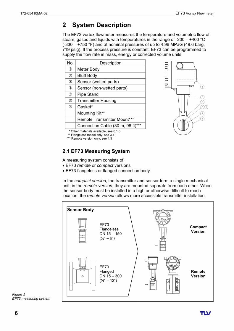
The EF73 vortex flowmeter measures the temperature and volumetric flow of steam, gases and liquids with temperatures in the range of -200 – +400 °C (-330 – +750 °F) and at nominal pressures of up to 4.96 MPaG (49.6 barg, 719 psig). If the process pressure is constant, EF73 can be programmed to supply the flow rate in mass, energy or corrected volume units.
No. Description
Meter Body
Bluff Body
Sensor (wetted parts)
Sensor (non-wetted parts)
Pipe Stand
Transmitter Housing
Gasket*
Mounting Kit**
Remote Transmitter Mount***
Connection Cable (30 m, 98 ft)*** * Other materials available, see 6.1.6
** Flangeless model only, see 3.4 *** Remote version only, see 4.3
2.1 EF73 Measuring System
A measuring system consists of: • EF73 remote or compact versions • EF73 flangeless or flanged connection body In the compact version, the transmitter and sensor form a single mechanical unit; in the remote version, they are mounted separate from each other. When the sensor body must be installed in a high or otherwise difficult to reach location, the remote version allows more accessible transmitter installation.
Sensor Body
EF73 Flangeless DN 15 – 150 (½” – 6”)
Compact Version
EF73 Flanged DN 15 – 300 (½” – 12”)
Remote Version
Figure 1 EF73 measuring system
EF73 Vortex Flowmeter 172-65410MA-02
7
3 Mounting and Installation
3.1 Transport
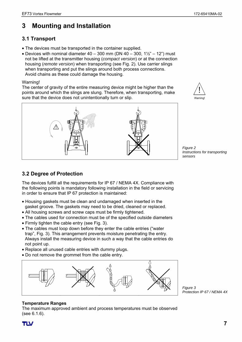
• The devices must be transported in the container supplied. • Devices with nominal diameter 40 – 300 mm (DN 40 – 300, 1½” – 12”) must
not be lifted at the transmitter housing (compact version) or at the connection housing (remote version) when transporting (see Fig. 2). Use carrier slings when transporting and put the slings around both process connections. Avoid chains as these could damage the housing.
Warning! The center of gravity of the entire measuring device might be higher than the points around which the slings are slung. Therefore, when transporting, make sure that the device does not unintentionally turn or slip.
E
3.2 Degree of Protection
The devices fulfill all the requirements for IP 67 / NEMA 4X. Compliance with the following points is mandatory following installation in the field or servicing in order to ensure that IP 67 protection is maintained:
• Housing gaskets must be clean and undamaged when inserted in the gasket groove. The gaskets may need to be dried, cleaned or replaced.
• All housing screws and screw caps must be firmly tightened. • The cables used for connection must be of the specified outside diameters • Firmly tighten the cable entry (see Fig. 3). • The cables must loop down before they enter the cable entries (“water
trap”, Fig. 3). This arrangement prevents moisture penetrating the entry. Always install the measuring device in such a way that the cable entries do not point up.
• Replace all unused cable entries with dummy plugs. • Do not remove the grommet from the cable entry.
Temperature Ranges The maximum approved ambient and process temperatures must be observed (see 6.1.6).
Figure 3 Protection IP 67 / NEMA 4X
Warning!
Figure 2 Instructions for transporting sensors
172-65410MA-02 EF73 Vortex Flowmeter
8
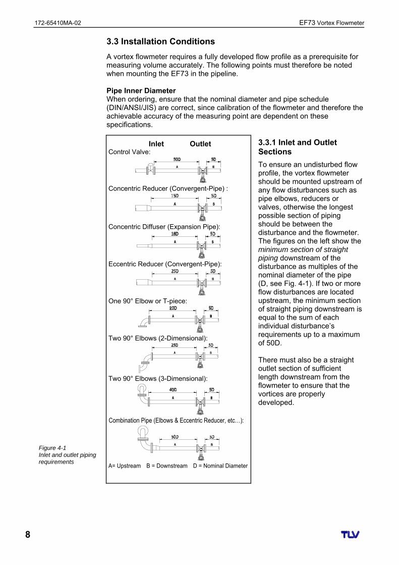
3.3 Installation Conditions
A vortex flowmeter requires a fully developed flow profile as a prerequisite for measuring volume accurately. The following points must therefore be noted when mounting the EF73 in the pipeline. Pipe Inner Diameter When ordering, ensure that the nominal diameter and pipe schedule (DIN/ANSI/JIS) are correct, since calibration of the flowmeter and therefore the achievable accuracy of the measuring point are dependent on these specifications.
Inlet Outlet Control Valve:
Concentric Reducer (Convergent-Pipe) :
Concentric Diffuser (Expansion Pipe):
Eccentric Reducer (Convergent-Pipe):
One 90° Elbow or T-piece:
Two 90° Elbows (2-Dimensional):
Two 90° Elbows (3-Dimensional):
Combination Pipe (Elbows & Eccentric Reducer, etc…):
A= Upstream B = Downstream D = Nominal Diameter
3.3.1 Inlet and Outlet Sections
To ensure an undisturbed flow profile, the vortex flowmeter should be mounted upstream of any flow disturbances such as pipe elbows, reducers or valves, otherwise the longest possible section of piping should be between the disturbance and the flowmeter. The figures on the left show the minimum section of straight piping downstream of the disturbance as multiples of the nominal diameter of the pipe (D, see Fig. 4-1). If two or more flow disturbances are located upstream, the minimum section of straight piping downstream is equal to the sum of each individual disturbance’s requirements up to a maximum of 50D. There must also be a straight outlet section of sufficient length downstream from the flowmeter to ensure that the vortices are properly developed.
Figure 4-1 Inlet and outlet piping requirements
EF73 Vortex Flowmeter 172-65410MA-02
9
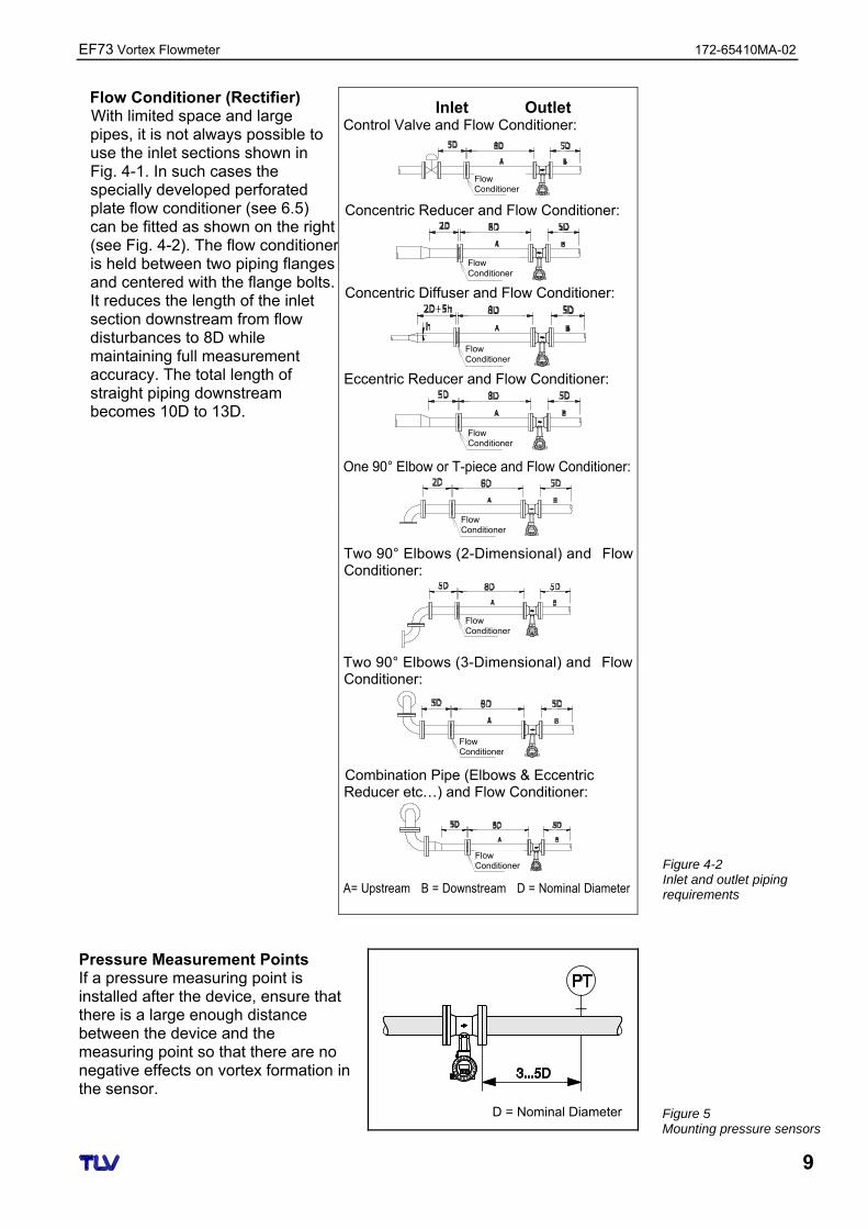
Flow Conditioner (Rectifier) With limited space and large pipes, it is not always possible to use the inlet sections shown in Fig. 4-1. In such cases the specially developed perforated plate flow conditioner (see 6.5) can be fitted as shown on the right (see Fig. 4-2). The flow conditioner is held between two piping flanges and centered with the flange bolts. It reduces the length of the inlet section downstream from flow disturbances to 8D while maintaining full measurement accuracy. The total length of straight piping downstream becomes 10D to 13D.
Inlet Outlet Control Valve and Flow Conditioner:
Concentric Reducer and Flow Conditioner:
Concentric Diffuser and Flow Conditioner:
Eccentric Reducer and Flow Conditioner:
One 90° Elbow or T-piece and Flow Conditioner:
Two 90° Elbows (2-Dimensional) and Flow Conditioner:
Two 90° Elbows (3-Dimensional) and Flow Conditioner:
Combination Pipe (Elbows & Eccentric Reducer etc…) and Flow Conditioner:
A= Upstream B = Downstream D = Nominal Diameter
Pressure Measurement Points If a pressure measuring point is installed after the device, ensure that there is a large enough distance between the device and the measuring point so that there are no negative effects on vortex formation in the sensor.
D = Nominal Diameter
Figure 5 Mounting pressure sensors
Figure 4-2 Inlet and outlet piping requirements
Flow Conditioner
Flow Conditioner
Flow Conditioner
Flow Conditioner
Flow Conditioner
Flow Conditioner
Flow Conditioner
Flow Conditioner
172-65410MA-02 EF73 Vortex Flowmeter
10
A EscE- +
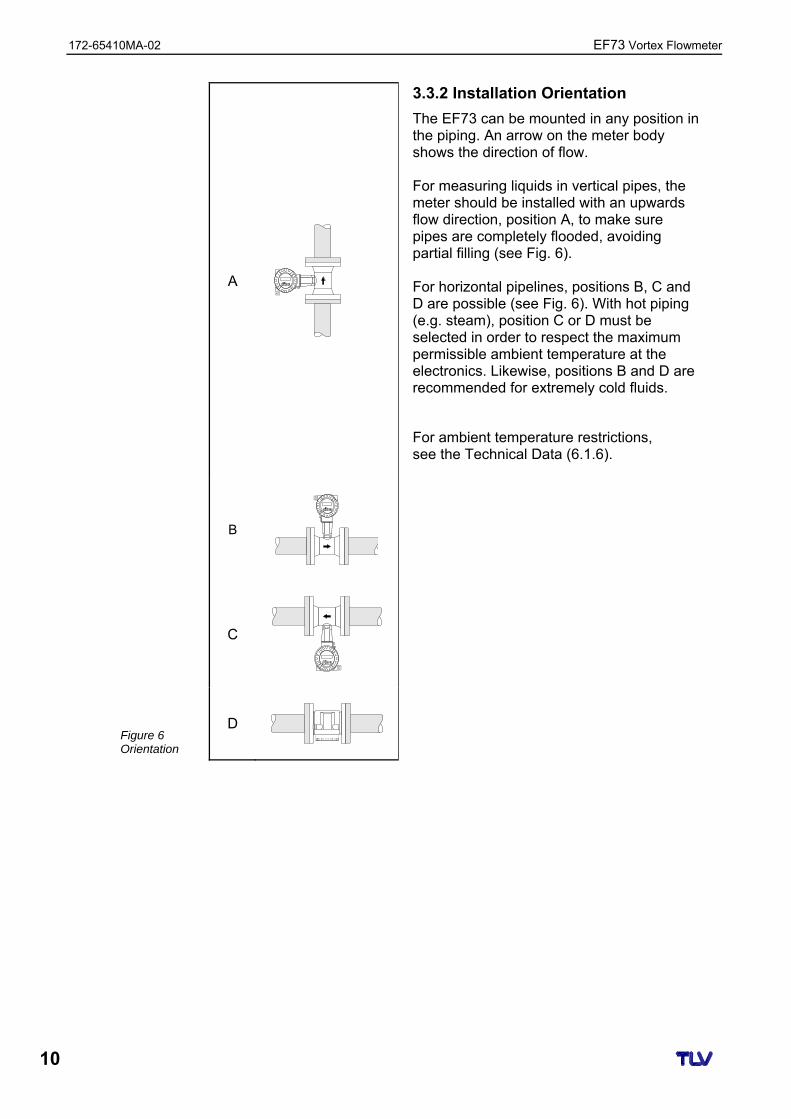
3.3.2 Installation Orientation
The EF73 can be mounted in any position in the piping. An arrow on the meter body shows the direction of flow. For measuring liquids in vertical pipes, the meter should be installed with an upwards flow direction, position A, to make sure pipes are completely flooded, avoiding partial filling (see Fig. 6). For horizontal pipelines, positions B, C and D are possible (see Fig. 6). With hot piping (e.g. steam), position C or D must be selected in order to respect the maximum permissible ambient temperature at the electronics. Likewise, positions B and D are recommended for extremely cold fluids.
For ambient temperature restrictions, see the Technical Data (6.1.6).
B
EscE- +
C
EscE- +
D
Figure 6 Orientation
EF73 Vortex Flowmeter 172-65410MA-02
11
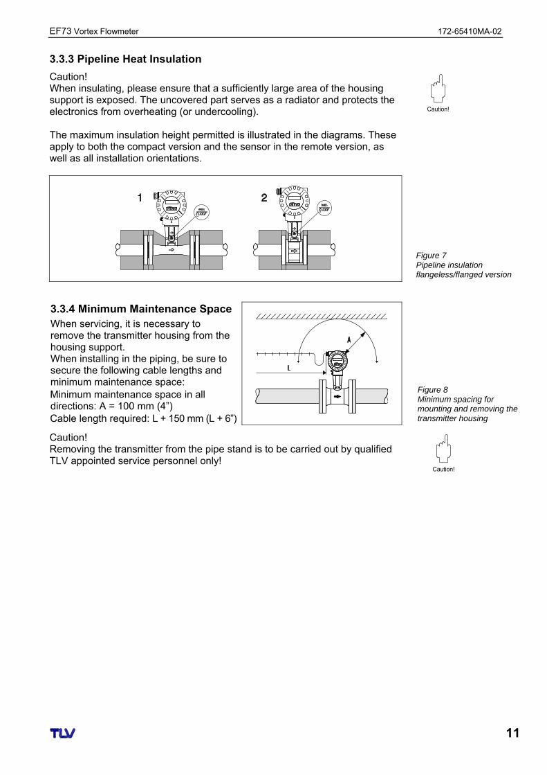
3.3.3 Pipeline Heat Insulation
Caution! When insulating, please ensure that a sufficiently large area of the housing support is exposed. The uncovered part serves as a radiator and protects the electronics from overheating (or undercooling). The maximum insulation height permitted is illustrated in the diagrams. These apply to both the compact version and the sensor in the remote version, as well as all installation orientations.
3.3.4 Minimum Maintenance Space When servicing, it is necessary to remove the transmitter housing from the housing support. When installing in the piping, be sure to secure the following cable lengths and minimum maintenance space: Minimum maintenance space in all directions: A = 100 mm (4”) Cable length required: L + 150 mm (L + 6”)
Caution! Removing the transmitter from the pipe stand is to be carried out by qualified TLV appointed service personnel only!
Figure 8 Minimum spacing for mounting and removing the transmitter housing
Caution!
Caution!
Figure 7 Pipeline insulation flangeless/flanged version
172-65410MA-02 EF73 Vortex Flowmeter
12
3.3.5 Other Considerations
Vibrations The correct operation of the measuring system is not influenced by plant vibrations up to 1 g, 10 – 500 Hz. Consequently, the sensors require no special measures for attachment. If higher levels of vibration are expected, be sure to secure piping before and after the flow meter. Preventing Excessive Flow To ensure long service life for the flowmeter, excessive instantaneous/ periodical flow rates should be held below the flow meter’s maximum flow rate. Failing to do so might result in damage to the sensor. Special care is necessary for steam at startup when the pressure is low, or when a valve is opened rapidly, such as by a solenoid valve, as excessive instantaneous flow rates often occur. Pulsating Influences Performance in air systems may be adversely affected if there are large variations or pulsating pressure from compressors and/or soot blowers. Use the procedures below to minimize pulsating pressures: • Move the source of the pulsations to the downstream side of the flowmeter.
Alternatively, put as much distance as possible between the source and the flowmeter.
• Install a pulsation dampening device, such as a chamber. • Close the valves before and after the flowmeter when there is no flow.
(This is to prevent false non-zero readings under zero-flow conditions.) Prevent Mixed Phase Flow This flowmeter is designed to measure both gases and liquids. However, accurate measurement cannot be guaranteed when gases and liquids are mixed together (i.e. gas-liquid mixed phase flow). Bypass Lines
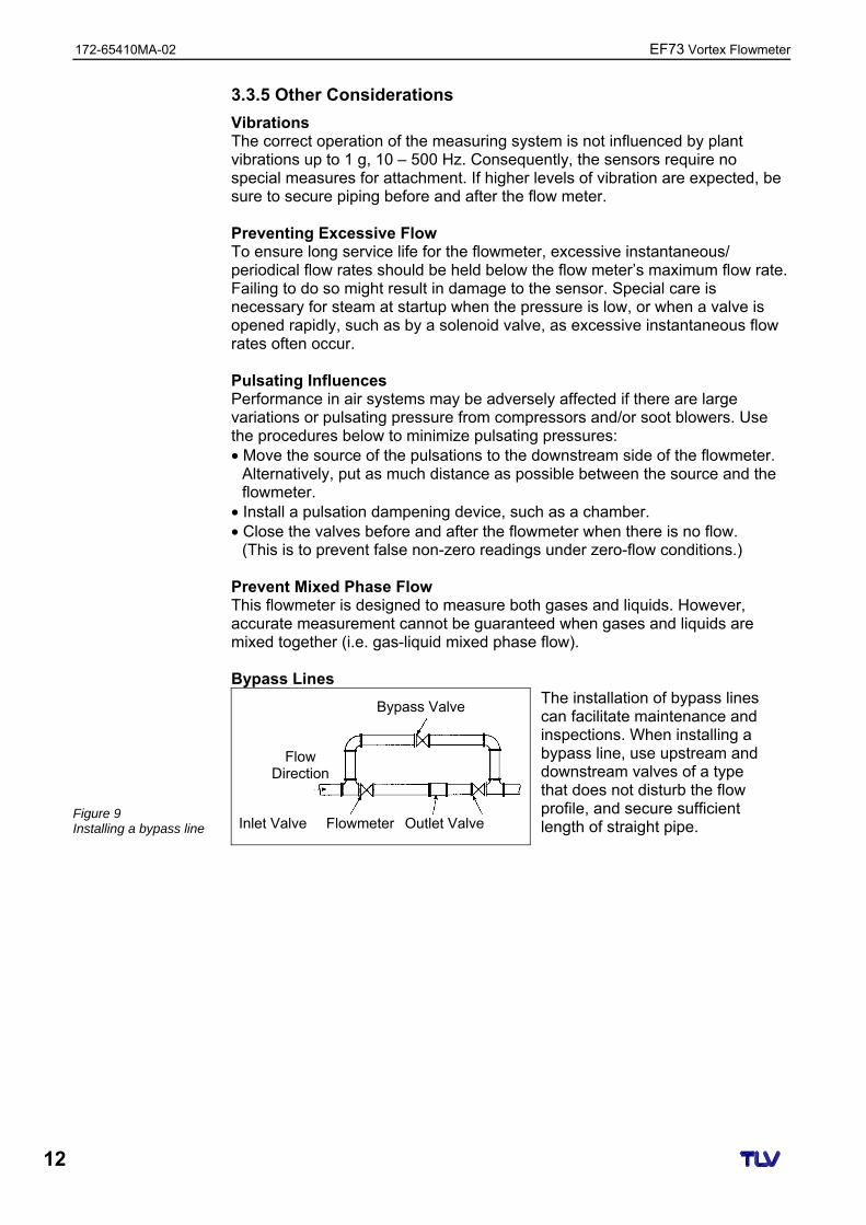
The installation of bypass lines can facilitate maintenance and inspections. When installing a bypass line, use upstream and downstream valves of a type that does not disturb the flow profile, and secure sufficient length of straight pipe.
Figure 9 Installing a bypass line
Bypass Valve
Inlet Valve Outlet Valve Flowmeter
Flow Direction
EF73 Vortex Flowmeter 172-65410MA-02
13
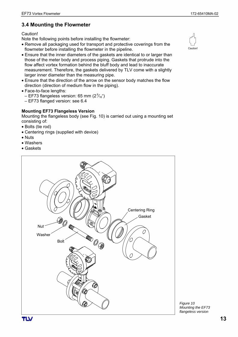
3.4 Mounting the Flowmeter
Caution! Note the following points before installing the flowmeter: • Remove all packaging used for transport and protective coverings from the
flowmeter before installing the flowmeter in the pipeline. • Ensure that the inner diameters of the gaskets are identical to or larger than
those of the meter body and process piping. Gaskets that protrude into the flow affect vortex formation behind the bluff body and lead to inaccurate measurement. Therefore, the gaskets delivered by TLV come with a slightly larger inner diameter than the measuring pipe.
• Ensure that the direction of the arrow on the sensor body matches the flow direction (direction of medium flow in the piping).
• Face-to-face lengths: – EF73 flangeless version: 65 mm (2
9⁄16”) – EF73 flanged version: see 6.4
Mounting EF73 Flangeless Version Mounting the flangeless body (see Fig. 10) is carried out using a mounting set consisting of: • Bolts (tie rod) • Centering rings (supplied with device) • Nuts • Washers • Gaskets
Centering Ring
Gasket
Bolt
Washer
Nut
Figure 10 Mounting the EF73 flangeless version
Caution!
172-65410MA-02 EF73 Vortex Flowmeter
14
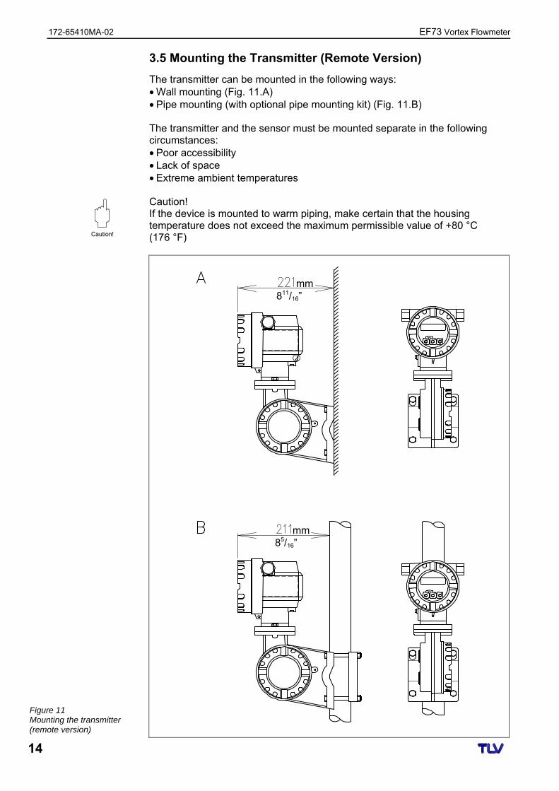
3.5 Mounting the Transmitter (Remote Version)
The transmitter can be mounted in the following ways: • Wall mounting (Fig. 11.A) • Pipe mounting (with optional pipe mounting kit) (Fig. 11.B) The transmitter and the sensor must be mounted separate in the following circumstances: • Poor accessibility • Lack of space • Extreme ambient temperatures Caution! If the device is mounted to warm piping, make certain that the housing temperature does not exceed the maximum permissible value of +80 °C (176 °F)
Figure 11 Mounting the transmitter (remote version)
Caution!
811/16”
85/16”
mm
mm
EF73 Vortex Flowmeter 172-65410MA-02
15
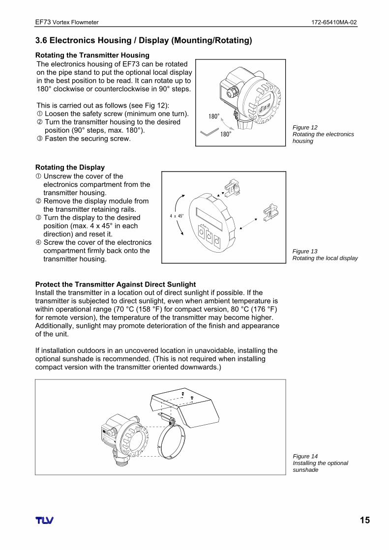
3.6 Electronics Housing / Display (Mounting/Rotating)
Rotating the Transmitter Housing The electronics housing of EF73 can be rotated on the pipe stand to put the optional local display in the best position to be read. It can rotate up to 180° clockwise or counterclockwise in 90° steps. This is carried out as follows (see Fig 12): Loosen the safety screw (minimum one turn). Turn the transmitter housing to the desired
position (90° steps, max. 180°). Fasten the securing screw.
180°
180°
Rotating the Display Unscrew the cover of the
electronics compartment from the transmitter housing.
Remove the display module from the transmitter retaining rails.
Turn the display to the desired position (max. 4 x 45° in each direction) and reset it.
Screw the cover of the electronics compartment firmly back onto the transmitter housing.
4 x 45°
csE
–
+
E
Protect the Transmitter Against Direct Sunlight Install the transmitter in a location out of direct sunlight if possible. If the transmitter is subjected to direct sunlight, even when ambient temperature is within operational range (70 °C (158 °F) for compact version, 80 °C (176 °F) for remote version), the temperature of the transmitter may become higher. Additionally, sunlight may promote deterioration of the finish and appearance of the unit. If installation outdoors in an uncovered location in unavoidable, installing the optional sunshade is recommended. (This is not required when installing compact version with the transmitter oriented downwards.)
AH+SSE
RDNE
RESU
RCIM
OLIPO
IIT
IP 65
O rdeCr ode:
S er N-. o :.
M essbe er ci h
M easurni g rangeU 163... 6 V D C
42... 0 m A
m ax.20 m
Made in Ge
rmany Maul
burg
>T
70°C:
A
t>85°C
Figure 12 Rotating the electronics housing
Figure 13 Rotating the local display
Figure 14 Installing the optional sunshade
172-65410MA-02 EF73 Vortex Flowmeter
16
4 Electrical Connection
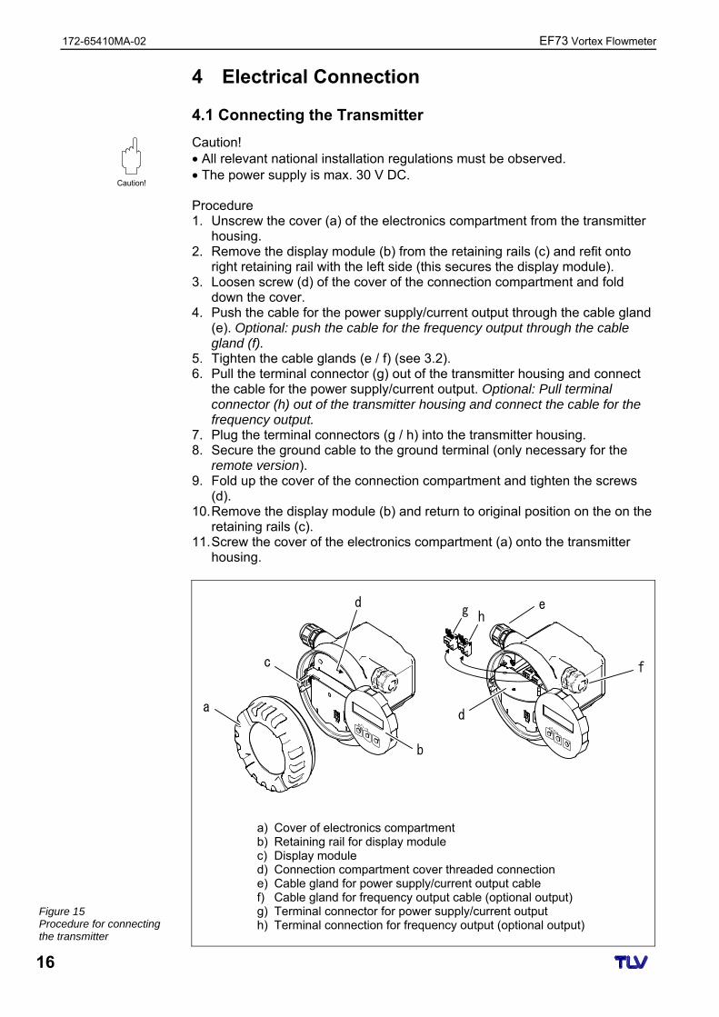
4.1 Connecting the Transmitter
Caution! • All relevant national installation regulations must be observed. • The power supply is max. 30 V DC. Procedure 1. Unscrew the cover (a) of the electronics compartment from the transmitter
housing. 2. Remove the display module (b) from the retaining rails (c) and refit onto
right retaining rail with the left side (this secures the display module). 3. Loosen screw (d) of the cover of the connection compartment and fold
down the cover. 4. Push the cable for the power supply/current output through the cable gland
(e). Optional: push the cable for the frequency output through the cable gland (f).
5. Tighten the cable glands (e / f) (see 3.2). 6. Pull the terminal connector (g) out of the transmitter housing and connect
the cable for the power supply/current output. Optional: Pull terminal connector (h) out of the transmitter housing and connect the cable for the frequency output.
7. Plug the terminal connectors (g / h) into the transmitter housing. 8. Secure the ground cable to the ground terminal (only necessary for the
remote version). 9. Fold up the cover of the connection compartment and tighten the screws
(d). 10. Remove the display module (b) and return to original position on the on the
retaining rails (c). 11. Screw the cover of the electronics compartment (a) onto the transmitter
housing.
e
f
g h
da
c
b
d
a) Cover of electronics compartment b) Retaining rail for display module c) Display module d) Connection compartment cover threaded connection e) Cable gland for power supply/current output cable f) Cable gland for frequency output cable (optional output) g) Terminal connector for power supply/current output h) Terminal connection for frequency output (optional output)
Caution!
Figure 15 Procedure for connecting the transmitter
EF73 Vortex Flowmeter 172-65410MA-02
17
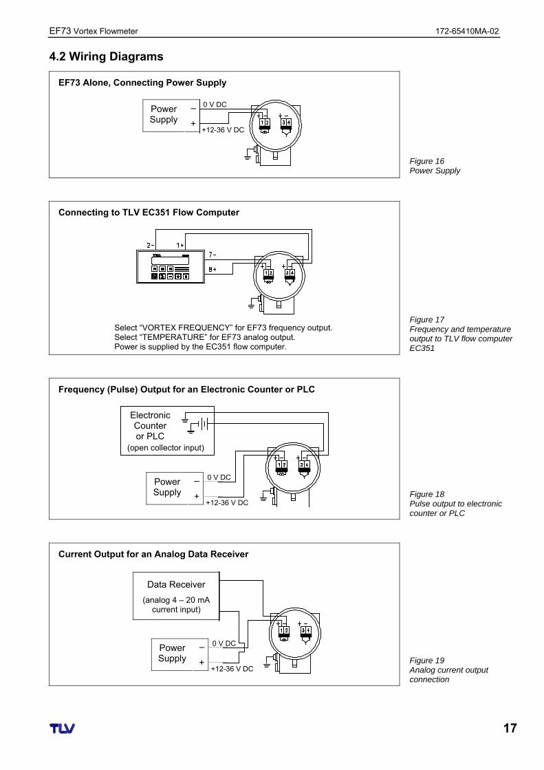
4.2 Wiring Diagrams
EF73 Alone, Connecting Power Supply
Connecting to TLV EC351 Flow Computer
Select “VORTEX FREQUENCY” for EF73 frequency output. Select “TEMPERATURE” for EF73 analog output. Power is supplied by the EC351 flow computer.
Frequency (Pulse) Output for an Electronic Counter or PLC
Current Output for an Analog Data Receiver
– Power Supply +
0 V DC
+12-36 V DC
(open collector input)
Electronic Counter or PLC
– Power Supply +
0 V DC
+12-36 V DC
– Power Supply +
0 V DC
+12-36 V DC
Data Receiver
(analog 4 – 20 mA current input)
Figure 16 Power Supply
Figure 17 Frequency and temperature output to TLV flow computer EC351
Figure 19 Analog current output connection
Figure 18 Pulse output to electronic counter or PLC
172-65410MA-02 EF73 Vortex Flowmeter
18
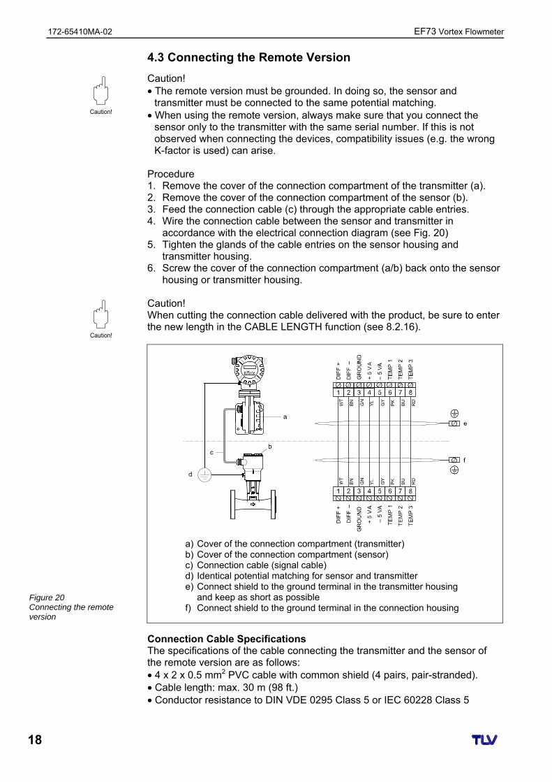
4.3 Connecting the Remote Version
Caution! • The remote version must be grounded. In doing so, the sensor and
transmitter must be connected to the same potential matching. • When using the remote version, always make sure that you connect the
sensor only to the transmitter with the same serial number. If this is not observed when connecting the devices, compatibility issues (e.g. the wrong K-factor is used) can arise.
Procedure 1. Remove the cover of the connection compartment of the transmitter (a). 2. Remove the cover of the connection compartment of the sensor (b). 3. Feed the connection cable (c) through the appropriate cable entries. 4. Wire the connection cable between the sensor and transmitter in
accordance with the electrical connection diagram (see Fig. 20) 5. Tighten the glands of the cable entries on the sensor housing and
transmitter housing. 6. Screw the cover of the connection compartment (a/b) back onto the sensor
housing or transmitter housing. Caution! When cutting the connection cable delivered with the product, be sure to enter the new length in the CABLE LENGTH function (see 8.2.16).
a) Cover of the connection compartment (transmitter) b) Cover of the connection compartment (sensor) c) Connection cable (signal cable) d) Identical potential matching for sensor and transmitter e) Connect shield to the ground terminal in the transmitter housing
and keep as short as possible f) Connect shield to the ground terminal in the connection housing
Connection Cable Specifications The specifications of the cable connecting the transmitter and the sensor of the remote version are as follows: • 4 x 2 x 0.5 mm2 PVC cable with common shield (4 pairs, pair-stranded). • Cable length: max. 30 m (98 ft.) • Conductor resistance to DIN VDE 0295 Class 5 or IEC 60228 Class 5
Figure 20 Connecting the remote version
Caution!
Caution!
EF73 Vortex Flowmeter 172-65410MA-02
19
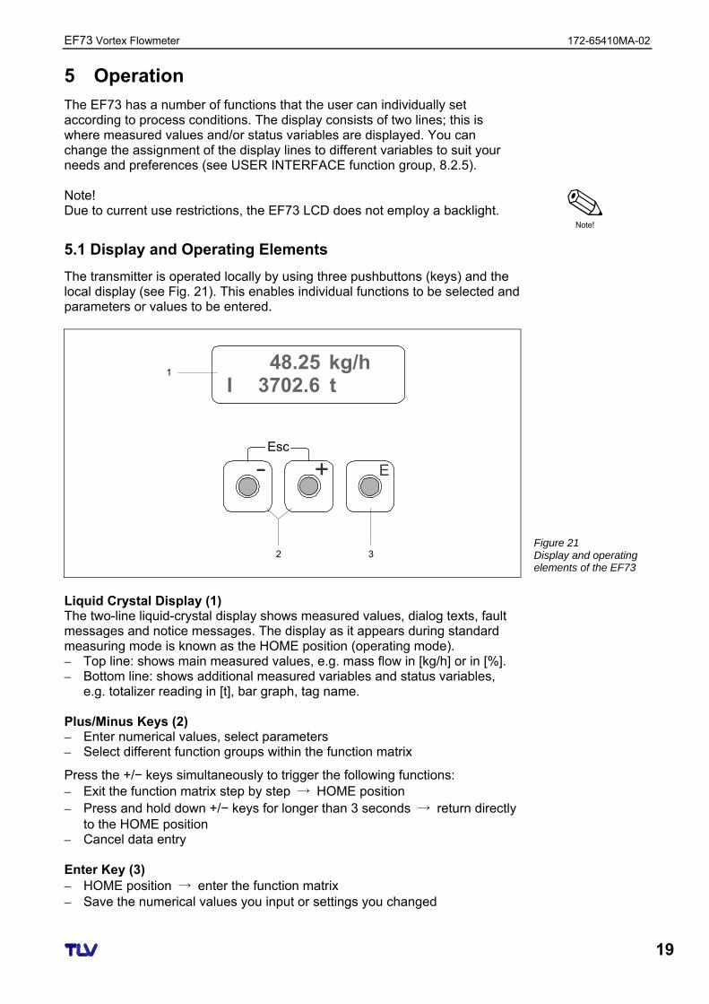
5 Operation
The EF73 has a number of functions that the user can individually set according to process conditions. The display consists of two lines; this is where measured values and/or status variables are displayed. You can change the assignment of the display lines to different variables to suit your needs and preferences (see USER INTERFACE function group, 8.2.5). Note! Due to current use restrictions, the EF73 LCD does not employ a backlight.
5.1 Display and Operating Elements
The transmitter is operated locally by using three pushbuttons (keys) and the local display (see Fig. 21). This enables individual functions to be selected and parameters or values to be entered.
Esc
E+
1
32
48.25 kg/h3702.6 tI
Liquid Crystal Display (1) The two-line liquid-crystal display shows measured values, dialog texts, fault messages and notice messages. The display as it appears during standard measuring mode is known as the HOME position (operating mode). – Top line: shows main measured values, e.g. mass flow in [kg/h] or in [%]. – Bottom line: shows additional measured variables and status variables,
e.g. totalizer reading in [t], bar graph, tag name. Plus/Minus Keys (2) – Enter numerical values, select parameters – Select different function groups within the function matrix
Press the +/− keys simultaneously to trigger the following functions: – Exit the function matrix step by step → HOME position – Press and hold down +/− keys for longer than 3 seconds → return directly
to the HOME position – Cancel data entry Enter Key (3) – HOME position → enter the function matrix – Save the numerical values you input or settings you changed
Note!
Figure 21 Display and operating elements of the EF73
172-65410MA-02 EF73 Vortex Flowmeter
20
5.2 Select Functions and Change Parameters
Note! When changing settings for the first time, you will be required to enter the ACCESS CODE. The initial factory setting is “73”. (See “Enabling the Programming Mode” below). The function matrix is a two-level construct: the function groups form one level and the groups’ functions the other. The groups are the highest-level grouping of the control options for the measuring device. A number of functions is assigned to each group. You select a group in order to access the individual functions for operating and configuring the measuring device. 1. From the HOME position, press E to enter the function matrix. 2. Cycle through the function groups by pressing + or - , then press E to
select. 3. Cycle through the functions by pressing E . 4. Press + / - to modify setting for the present function. Press E to save
the new setting and proceed to the next function. 5. To change function settings in a different function group, press the Esc key
(+ + - ), then repeat from step 2. 6. To exit the function matrix (return to HOME position):
– Press and hold down the Esc key (+ + - ) for longer than 3 seconds to return directly – Repeatedly press Esc key (+ + - ) to return step by step
Note! • Certain functions prompt you to confirm your data entries. Press + / - to
select “SURE [ YES ]” and press E to confirm. This saves your setting or starts a function, as applicable.
• Return to the HOME position is automatic if no key is pressed for 5 minutes. • Programming mode is automatically disabled if you do not press a key within
60 seconds following return to the HOME position. Enabling the Programming Mode The function matrix can be disabled. Disabling the function matrix rules out the possibility of inadvertent changes to device functions, numerical values or factory settings. A numerical code (factory setting = 73) must be entered before settings can be changed. If you use a code number of your choice, you exclude the possibility of unauthorized persons accessing data (see ACCESS CODE function, 8.2.4).
Note!
Note!

EF73 Vortex Flowmeter 172-65410MA-02
21
6 Technical Data
6.1 Technical Data at a Glance
6.1.1 Application
The measuring system is used to measure the flow of saturated steam, superheated steam, gases and liquids. The measured variables volume flow and temperature are measured primarily. From these values, the device can used stored data on the density and enthalpy to calculate and output the mass flow and heat flow for example.
6.1.2 Function and System Design
Vortex flow measurement on the principle of the Karman vortex street. The measuring system consists of a transmitter and a sensor. Two versions are available: • Compact version: Transmitter and sensor form a single mechanical unit. • Remote version: Sensor is mounted separate from the transmitter.
6.1.3 Input
• Volumetric flow (volume flow) → is proportional to the frequency of vortex shedding after the bluff body.
• Temperature → can be output directly and is used to calculate the mass flow for example.
The measured process variables volume flow, temperature or the calculated process variables mass flow, heat flow or corrected volume flow can be output as output variables. The measuring range depends on the fluid and the pipe diameter. Start of Measuring Range: Depends on the density and the Reynolds number (Remin = 4 000, Relinear = 20 000). The Reynolds number is dimensionless and indicates the ratio of a fluid’s inertial forces to its viscous forces. It is used to characterize the flow. The Reynolds number is calculated as follows:
d · V Re = ν
Re = Reynolds number d = pipe diameter V = velocity ν = viscosity
Full Scale Value: • Gas, steam: vmax = 75 m/s (246 ft/s) (DN 15: vmax = 46 m/s (151 ft/s)) • Liquids: vmax = 9 m/s (30 ft/s)
Measuring Principle
Measuring System
Measured Variable
Measuring Range
172-65410MA-02 EF73 Vortex Flowmeter
22
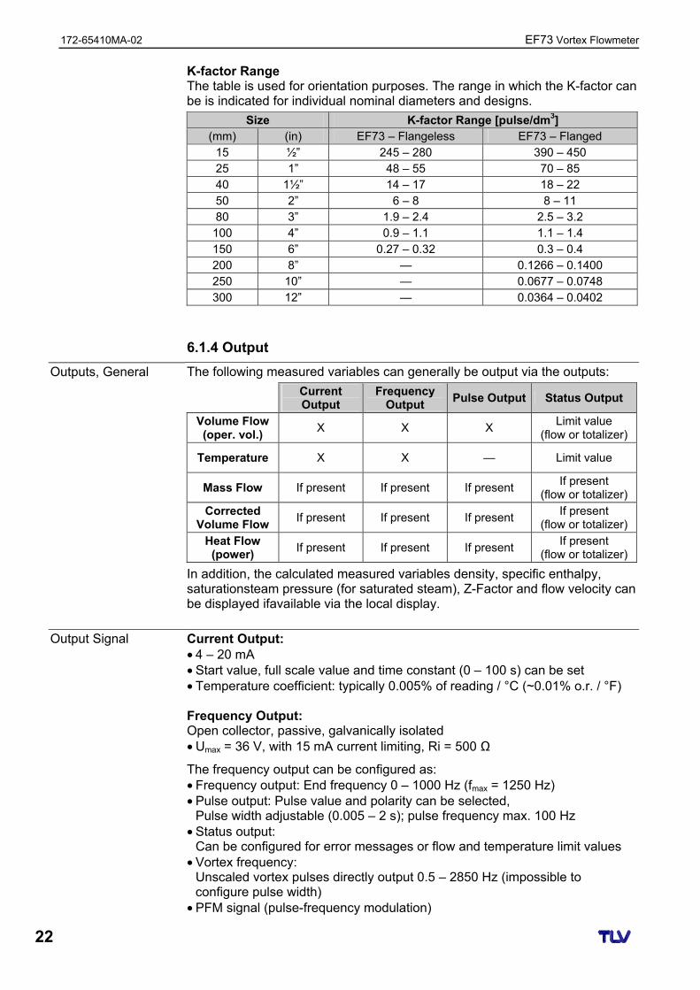
K-factor Range The table is used for orientation purposes. The range in which the K-factor can be is indicated for individual nominal diameters and designs.
Size K-factor Range [pulse/dm3] (mm) (in) EF73 – Flangeless EF73 – Flanged
15 ½” 245 – 280 390 – 450 25 1” 48 – 55 70 – 85 40 1½” 14 – 17 18 – 22 50 2” 6 – 8 8 – 11 80 3” 1.9 – 2.4 2.5 – 3.2 100 4” 0.9 – 1.1 1.1 – 1.4 150 6” 0.27 – 0.32 0.3 – 0.4 200 8” — 0.1266 – 0.1400 250 10” — 0.0677 – 0.0748 300 12” — 0.0364 – 0.0402
6.1.4 Output
The following measured variables can generally be output via the outputs:
Current Output
Frequency Output
Pulse Output Status Output
Volume Flow (oper. vol.)
X X X Limit value
(flow or totalizer)
Temperature X X — Limit value
Mass Flow If present If present If present If present
(flow or totalizer)
Corrected Volume Flow
If present If present If present If present
(flow or totalizer)
Heat Flow (power)
If present If present If present If present
(flow or totalizer)
In addition, the calculated measured variables density, specific enthalpy, saturationsteam pressure (for saturated steam), Z-Factor and flow velocity can be displayed ifavailable via the local display.
Current Output: • 4 – 20 mA • Start value, full scale value and time constant (0 – 100 s) can be set • Temperature coefficient: typically 0.005% of reading / °C (~0.01% o.r. / °F) Frequency Output: Open collector, passive, galvanically isolated • Umax = 36 V, with 15 mA current limiting, Ri = 500 Ω
The frequency output can be configured as: • Frequency output: End frequency 0 – 1000 Hz (fmax = 1250 Hz) • Pulse output: Pulse value and polarity can be selected,
Pulse width adjustable (0.005 – 2 s); pulse frequency max. 100 Hz • Status output:
Can be configured for error messages or flow and temperature limit values • Vortex frequency:
Unscaled vortex pulses directly output 0.5 – 2850 Hz (impossible to configure pulse width)
• PFM signal (pulse-frequency modulation)
Outputs, General
Output Signal
EF73 Vortex Flowmeter 172-65410MA-02
23
• Current output: failsafe mode can be selected (e.g. in accordance with NAMUR Recommendation NE 43)
• Frequency output: failsafe mode can be selected • Status output: “not conductive” during fault
0
100
200
300
400
500
600
700
800
900
1000
1100
36302520151018
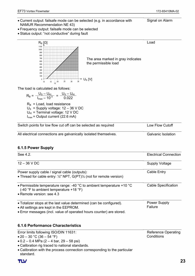
The load is calculated as follows:
US – UKI US – UKI RB = Imax – 10-3
=0.022
RB = Load, load resistance US = Supply voltage: 12 – 36 V DC UKI = Terminal voltage: 12 V DC Imax = Output current (22.6 mA)
Switch points for low flow cut off can be selected as required All electrical connections are galvanically isolated themselves.
6.1.5 Power Supply
See 4.2. 12 – 36 V DC Power supply cable / signal cable (outputs): • Thread for cable entry: ½" NPT, G(PT)½ (not for remote version) • Permissible temperature range: -40 °C to ambient temperature +10 °C
(-40 °F to ambient temperature +18 °F) • Remote version: see 4.3 • Totalizer stops at the last value determined (can be configured). • All settings are kept in the EEPROM. • Error messages (incl. value of operated hours counter) are stored.
6.1.6 Performance Characteristics
Error limits following ISO/DIN 11631: • 20 – 30 °C (36 – 54 °F) • 0.2 – 0.4 MPa (2 – 4 bar, 29 – 58 psi) • Calibration rig traced to national standards. • Calibration with the process connection corresponding to the particular
standard.
Signal on Alarm
Load RB [Ω]
US [V]
The area marked in gray indicates the permissible load
Low Flow Cutoff
Galvanic Isolation
Electrical Connection
Supply Voltage
Cable Entry
Cable Specification
Power Supply Failure
Reference Operating Conditions
172-65410MA-02 EF73 Vortex Flowmeter
24
• Volume flow (liquid): ±0.75% o.r. for Re > 20 000 ± 0.75% o.f.s. for Re between 4000 – 20 000
• Volume flow (gas/steam):
±1% o.r. for Re > 20 000 ±1% o.f.s. for Re between 4000 – 20 000
• Temperature:
±1 °C (T > 100 °C, saturated steam); ±2 °F (T > 212 °F, saturated steam); Risetime 50% (agitated under water, following IEC 60751): 8 s
• Mass flow (saturated steam):
- For flow velocities v 20 – 50 m/s, T > 150 °C (423 K, 302 °F) ±1.7% (2% for remote version) o.r. for Re > 20 000 ±1.7% (2% for remote version) o.f.s. for Re between 4000 – 20 000 - For flow velocities v 10 – 70 m/s, T > 140 °C (413 K, 284 °F) ±2% (2.3% for remote version) o.r. for Re > 20 000 ±2% (2.3% for remote version) o.f.s. for Re between 4000 – 20 000
• Mass flow (other fluids):
Depends on the pressure value, specified in the OPERATING PRESSURE function (see 8.2.13). An individual error observation must be carried out.
o.r. = of measured value, o.f.s = of full scale value, Re = Reynolds number ±0.25% o.r. (of measured value) Environment • Compact Version: -40 – +70 °C (-40 – +158 °F)
Display can be read between -20 °C – +70 °C (-4 – +158 °F) • Remote Version – Sensor: -40 – +85 °C (-40 – +185 °F)
Remote Version – Transmitter: -40 – +80 °C (-40 – +176 °F) Display can be read between -20 °C – +70 °C (-4 – +158 °F)
Caution! When mounting outside, we recommend you protect from direct sunlight with a sunshade (optional part), especially in warmer climates with high ambient temperatures. -40 – +80 °C (-40 – +176 °F) P 67 (NEMA 4X) in accordance with EN 60529 Acceleration up to 1 g, 10 – 500 Hz, following IEC 60068-2-6 To EN 61326/A1 and NAMUR Recommendation NE 21
Maximum Measured Error
Repeatability
Ambient Temperature Range
Caution!
Storage Temperature
Degree of Protection
Vibration Resistance
Electromagnetic Compatibility (EMC)
EF73 Vortex Flowmeter 172-65410MA-02
25
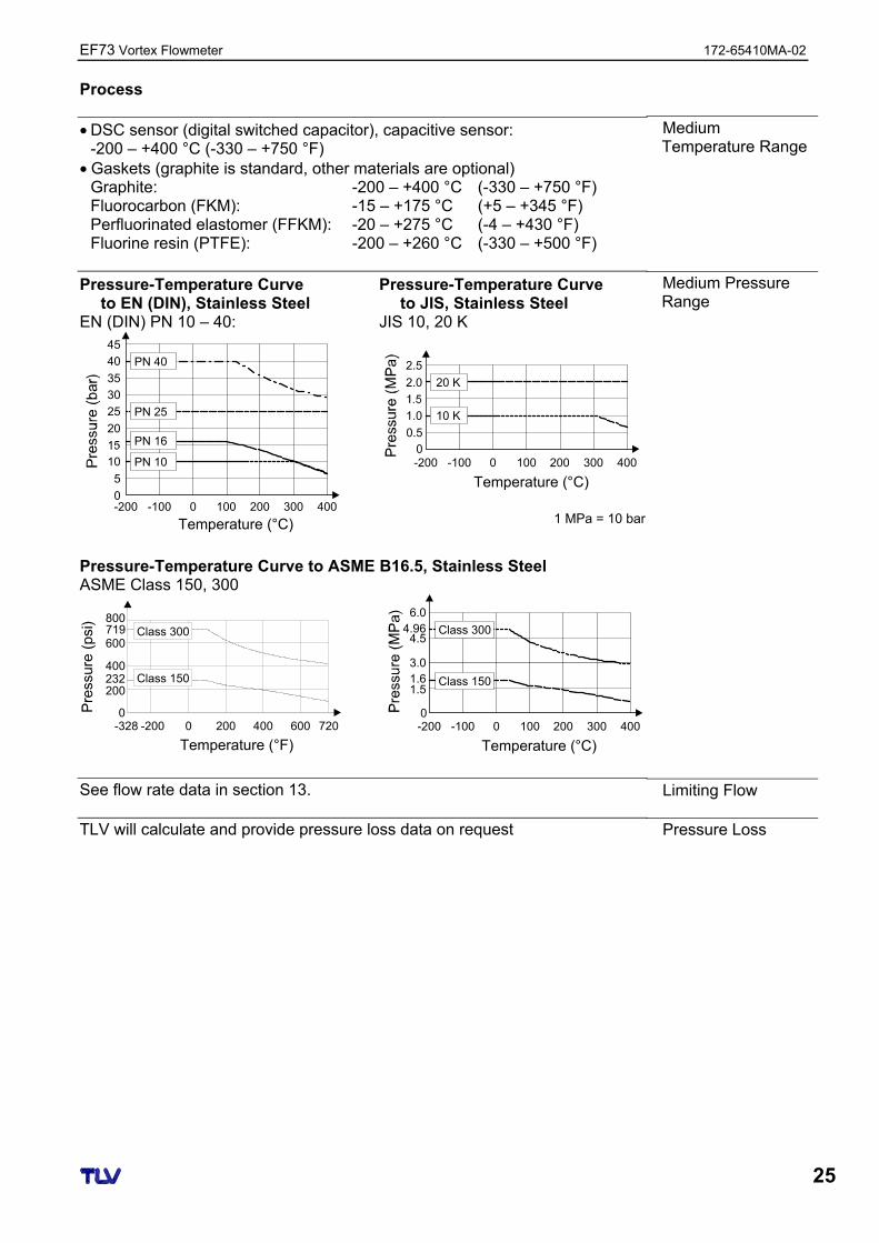
Process • DSC sensor (digital switched capacitor), capacitive sensor:
-200 – +400 °C (-330 – +750 °F) • Gaskets (graphite is standard, other materials are optional)
Graphite: -200 – +400 °C (-330 – +750 °F) Fluorocarbon (FKM): -15 – +175 °C (+5 – +345 °F) Perfluorinated elastomer (FFKM): -20 – +275 °C (-4 – +430 °F) Fluorine resin (PTFE): -200 – +260 °C (-330 – +500 °F)
Pressure-Temperature Curve to EN (DIN), Stainless Steel
EN (DIN) PN 10 – 40:
-200 -1000
5
10
20
25
30
35
40
45
0 100 200 300 400
Temperature (°C)
PN 40
PN 25
PN 16
PN 10
Pressure-Temperature Curve to JIS, Stainless Steel
JIS 10, 20 K
Temperature (°C)-200 -100 0 100 200 300 4000
0.5
1.0
2.0
2.5
20 K
10 K
1 MPa = 10 bar
Pressure-Temperature Curve to ASME B16.5, Stainless Steel ASME Class 150, 300
Temperature (°F)-328 -2000
200
400
600
800
0 200 400 600 720
Class 150
Class 300719
232
Temperature (°C)
-200 -1000
1.5
3.0
4.5
6.0
0 100 200 300 400
Class 150
Class 3004.96
1.6
See flow rate data in section 13. TLV will calculate and provide pressure loss data on request
Medium Temperature Range
Medium Pressure Range
Limiting Flow
Pressure Loss
172-65410MA-02 EF73 Vortex Flowmeter
26
6.1.7 Mechanical Construction
See 6.2, 6.3 and 6.4. • Transmitter housing: Powder-coated die-cast aluminum • Sensor: Stainless steel, A351-CF3M (1.4404) • Flanges: Stainless steel, A351-CF3M (1.4404)
ASME/JIS, DN 15 – 150, ½" – 6": Stainless steel, weld-on flanges, 316/316L • DSC sensor (differential switched capacitor; capacitive sensor):
Wetted parts: Stainless steel 1.4435 (316L) Non-wetted parts: Stainless steel 1.4301 (CF3)
• Pipe stand: Stainless steel, 1.4308 (CF8) • Gasket: Graphite (standard; see above)
6.1.8 Human Interface
• Liquid crystal display, two-line, plain text display, 16 characters per line • Display can be configured individually, e.g. for measured variables and
status variables, totalizers • Local operation with three keys (+ , - , E ) • Quick Setup for quick commissioning
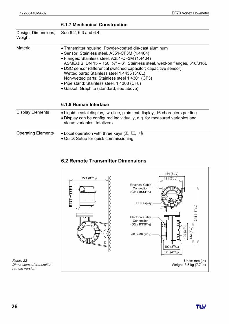
6.2 Remote Transmitter Dimensions
Units: mm (in)
Weight: 3.5 kg (7.7 lb)
Design, Dimensions, Weight
Material
Display Elements
Operating Elements
221 (811/16)
154 (61/16)
141 (59/16)
100 (315/16)
123 (413/16)
100
(31
5/ 1
6)
133
(51/ 4
)
348
(131
1/ 1
6)
Electrical Cable Connection
(G½ / BSSP½)
Electrical Cable Connection
(G½ / BSSP½)
LED Display
ø8.6-M8 (ø5/16)
Figure 22 Dimensions of transmitter, remote version
EF73 Vortex Flowmeter 172-65410MA-02
27
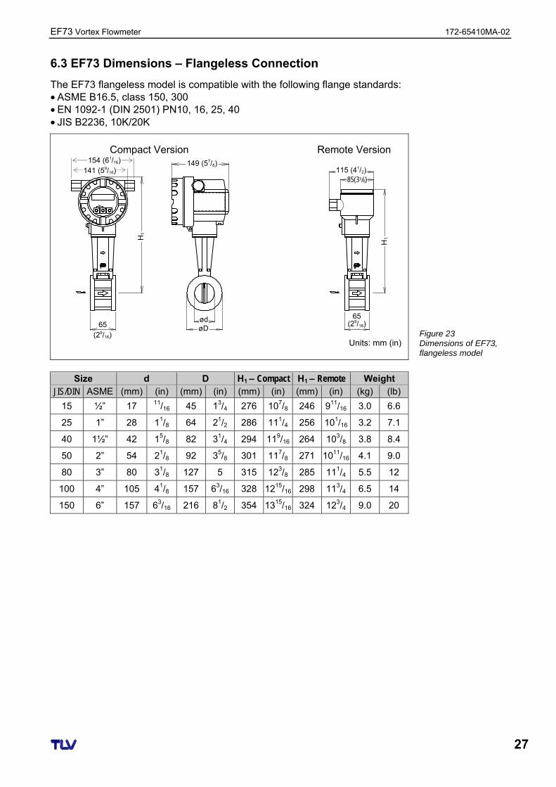
6.3 EF73 Dimensions – Flangeless Connection
The EF73 flangeless model is compatible with the following flange standards: • ASME B16.5, class 150, 300 • EN 1092-1 (DIN 2501) PN10, 16, 25, 40 • JIS B2236, 10K/20K
Compact Version Remote Version
Units: mm (in)
Size d D H1 – Compact H1 – Remote Weight JIS/DIN ASME (mm) (in) (mm) (in) (mm) (in) (mm) (in) (kg) (lb)
15 ½” 17 11/16 45 13/4 276 107/8 246 911/16 3.0 6.6
25 1” 28 11/8 64 21/2 286 111/4 256 101/16 3.2 7.1
40 1½” 42 15/8 82 31/4 294 119/16 264 103/8 3.8 8.4
50 2” 54 21/8 92 35/8 301 117/8 271 1011/16 4.1 9.0
80 3” 80 31/8 127 5 315 123/8 285 111/4 5.5 12
100 4” 105 41/8 157 63/16 328 1215/16 298 113/4 6.5 14
150 6” 157 63/16 216 81/2 354 1315/16 324 123/4 9.0 20
149 (57/8)
H1
H1
65 (29/16)
65 (29/16)
115 (41/2)85(33/8)
ød øD
Figure 23 Dimensions of EF73, flangeless model
154 (61/16) 141 (59/16)
172-65410MA-02 EF73 Vortex Flowmeter
28
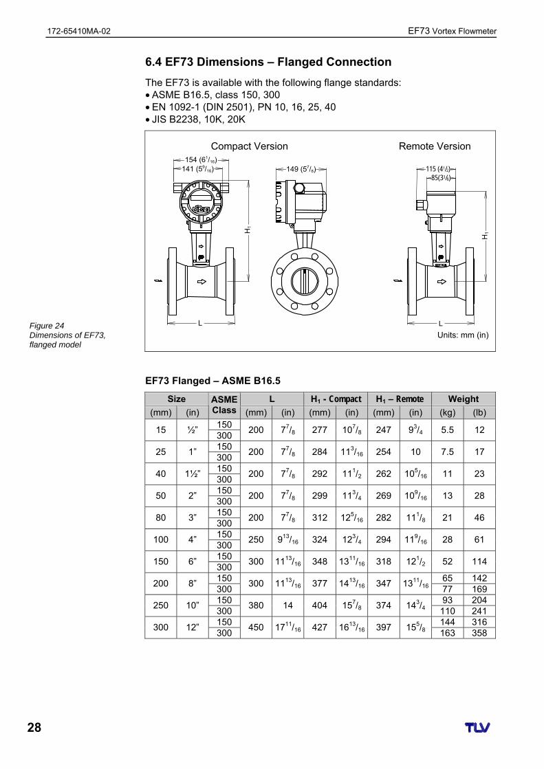
6.4 EF73 Dimensions – Flanged Connection
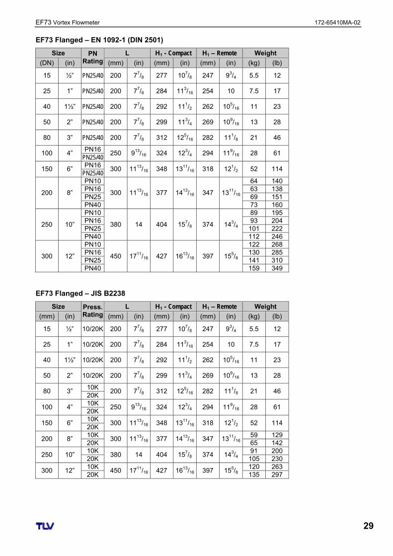
The EF73 is available with the following flange standards: • ASME B16.5, class 150, 300 • EN 1092-1 (DIN 2501), PN 10, 16, 25, 40 • JIS B2238, 10K, 20K
Compact Version Remote Version
Units: mm (in) EF73 Flanged – ASME B16.5
Size L H1 - Compact H1 – Remote Weight
(mm) (in)
ASMEClass (mm) (in) (mm) (in) (mm) (in) (kg) (lb) 150
15 ½” 300
200 77/8 277 107/8 247 93/4 5.5 12
150 25 1”
300 200 77/8 284 113/16 254 10 7.5 17
150 40 1½”
300 200 77/8 292 111/2 262 105/16 11 23
150 50 2”
300 200 77/8 299 113/4 269 109/16 13 28
150 80 3”
300 200 77/8 312 125/16 282 111/8 21 46
150 100 4”
300 250 913/16 324 123/4 294 119/16 28 61
150 150 6”
300 300 1113/16 348 1311/16 318 121/2 52 114
150 65 142 200 8”
300 300 1113/16 377 1413/16 347 1311/16 77 169
150 93 204 250 10”
300 380 14 404 157/8 374 143/4 110 241
150 144 316 300 12”
300 450 1711/16 427 1613/16 397 155/8 163 358
149 (57/8)
H1
H1
L
154 (61/16) 115 (41/2)
85(33/8)
L
141 (59/16)
Figure 24 Dimensions of EF73, flanged model
EF73 Vortex Flowmeter 172-65410MA-02
29
EF73 Flanged – EN 1092-1 (DIN 2501)
Size L H1 - Compact H1 – Remote Weight
(DN) (in)
PN Rating (mm) (in) (mm) (in) (mm) (in) (kg) (lb)
15 ½” PN25/40 200 77/8 277 107/8 247 93/4 5.5 12
25 1” PN25/40 200 77/8 284 113/16 254 10 7.5 17
40 1½” PN25/40 200 77/8 292 111/2 262 105/16 11 23
50 2” PN25/40 200 77/8 299 113/4 269 109/16 13 28
80 3” PN25/40 200 77/8 312 125/16 282 111/8 21 46
PN16 100 4”
PN25/40 250 913/16 324 123/4 294 119/16 28 61
PN16 150 6”
PN25/40 300 1113/16 348 1311/16 318 121/2 52 114
PN10 64 140 PN16 63 138 PN25 69 151
200 8”
PN40
300 1113/16 377 1413/16 347 1311/16
73 160 PN10 89 195 PN16 93 204 PN25 101 222
250 10”
PN40
380 14 404 157/8 374 143/4
112 246 PN10 122 268 PN16 130 285 PN25 141 310
300 12”
PN40
450 1711/16 427 1613/16 397 155/8
159 349 EF73 Flanged – JIS B2238
Size L H1 - Compact H1 – Remote Weight
(mm) (in)
Press. Rating (mm) (in) (mm) (in) (mm) (in) (kg) (lb)
15 ½” 10/20K 200 77/8 277 107/8 247 93/4 5.5 12
25 1” 10/20K 200 77/8 284 113/16 254 10 7.5 17
40 1½” 10/20K 200 77/8 292 111/2 262 105/16 11 23
50 2” 10/20K 200 77/8 299 113/4 269 109/16 13 28
10K 80 3”
20K 200 77/8 312 125/16 282 111/8 21 46
10K 100 4”
20K 250 913/16 324 123/4 294 119/16 28 61
10K 150 6”
20K 300 1113/16 348 1311/16 318 121/2 52 114
10K 59 129 200 8”
20K 300 1113/16 377 1413/16 347 1311/16 65 142
10K 91 200 250 10”
20K 380 14 404 157/8 374 143/4 105 230
10K 120 263 300 12”
20K 450 1711/16 427 1613/16 397 155/8 135 297
172-65410MA-02 EF73 Vortex Flowmeter
30
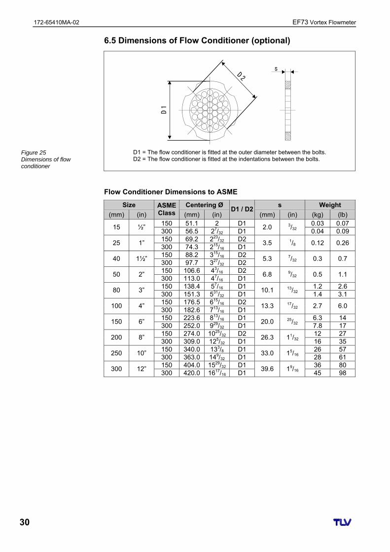
6.5 Dimensions of Flow Conditioner (optional)
s2D
1D
D1 = The flow conditioner is fitted at the outer diameter between the bolts. D2 = The flow conditioner is fitted at the indentations between the bolts.
Flow Conditioner Dimensions to ASME
Size Centering Ø s Weight
(mm) (in)
ASMEClass (mm) (in)
D1 / D2(mm) (in) (kg) (lb)
150 51.1 2 D1 0.03 0.07 15 ½”
300 56.5 27/32 D1 2.0 3/32 0.04 0.09
150 69.2 223/32 D2 25 1”
300 74.3 215/16 D1 3.5 1/8 0.12 0.26
150 88.2 315/16 D2 40 1½”
300 97.7 327/32 D2 5.3 7/32 0.3 0.7
150 106.6 43/16 D2 50 2”
300 113.0 47/16 D1 6.8 9/32 0.5 1.1
150 138.4 57/16 D1 1.2 2.6 80 3”
300 151.3 531/32 D1 10.1 13/32 1.4 3.1
150 176.5 615/16 D2 100 4”
300 182.6 713/16 D1 13.3 17/32 2.7 6.0
150 223.6 813/16 D1 6.3 14 150 6”
300 252.0 929/32 D1 20.0 25/32 7.8 17
150 274.0 1025/32 D2 12 27 200 8”
300 309.0 125/32 D1 26.3 11/32 16 35
150 340.0 133/8 D1 26 57 250 10”
300 363.0 149/32 D1 33.0 15/16 28 61
150 404.0 1529/32 D1 36 80 300 12”
300 420.0 1617/16 D1 39.6 19/16 45 98
Figure 25 Dimensions of flow conditioner
EF73 Vortex Flowmeter 172-65410MA-02
31
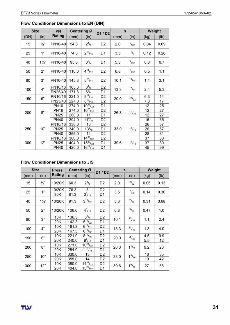
Flow Conditioner Dimensions to EN (DIN)
Size Centering Ø s Weight
(DN) (in)
PN Rating (mm) (in)
D1 / D2(mm) (in) (kg) (lb)
15 ½” PN10-40 54.3 21/8 D2 2.0 3/32 0.04 0.09
25 1” PN10-40 74.3 215/16 D1 3.5 1/8 0.12 0.26
40 1½” PN10-40 95.3 33/4 D1 5.3 7/32 0.3 0.7
50 2” PN10-40 110.0 411/32 D2 6.8 9/32 0.5 1.1
80 3” PN10-40 145.3 525/32 D2 10.1 13/32 1.4 3.1
PN10/16 165.3 61/2 D2 100 4”
PN25/40 171.3 63/4 D1 13.3 17/32 2.4 5.3
PN10/16 221.0 811/16 D2 6.3 14 150 6”
PN25/40 227.0 815/16 D2 20.0 25/32 7.8 17
PN10 274.0 1025/32 D1 12 25 PN16 274.0 1025/32 D2 12 27 PN25 280.0 11 D1 12 27
200 8”
PN40 294.0 119/16 D2
26.3 11/32
16 35 PN10/16 330.0 13 D2 26 57
PN25 340.0 133/8 D1 26 57 250 10” PN40 355.0 14 D2
33.0 15/16 28 61
PN10/16 380.0 1431/32 D2 37 80 PN25 404.0 1529/32 D1 37 80 300 12” PN40 420.0 1617/16 D1
39.6 19/16 45 99
Flow Conditioner Dimensions to JIS
Size Centering Ø s Weight
(mm) (in)
Press. Rating (mm) (in)
D1 / D2(mm) (in) (kg) (lb)
15 ½” 10/20K 60.3 23/8 D2 2.0 3/32 0.06 0.13
10/20K 76.3 3 D2 25 1”
30K 81.3 33/16 D1 3.5 1/8 0.14 0.30
40 1½” 10/20K 91.3 319/32 D2 5.3 7/32 0.31 0.68
50 2” 10/20K 106.6 43/16 D2 6.8 9/32 0.47 1.0
10K 136.3 53/8 D2 80 3”
20K 142.3 519/32 D1 10.1 13/32 1.1 2.4
10K 161.3 611/32 D2 100 4”
20K 167.3 619/32 D1 13.3 17/32 1.8 4.0
10K 221.0 811/16 D2 4.5 9.9 150 6”
20K 240.0 97/16 D1 20.0 25/32 5.5 12
10K 271.0 1021/32 D2 200 8”
20K 284.0 113/16 D1 26.3 11/32 9.2 20
10K 330.0 13 D2 16 35 250 10”
20K 355.0 14 D2 33.0 15/16 19 42
10K 380.0 1431/32 D2 300 12”
20K 404.0 1529/32 D1 39.6 19/16 27 58
172-65410MA-02 EF73 Vortex Flowmeter
32
7 Commissioning
7.1 Function Check
Make sure that all final checks regarding installation and wiring have been completed before you commission your measuring point.
7.2 Commissioning
7.2.1 Switching on the Measuring Device
Once the function checks have been successfully completed, it is time to switch on the supply voltage. After approximately 5 seconds, the device is ready for operation. The measuring device performs a number of internal test functions after power-up. As this procedure progresses, the following message appears on the local display:
PROWIRL 73VX.XX.XX
Start-up message. Displays the current software (example).
Normal measuring mode commences as soon as start-up completes. Various measured values and/or status variables appear on the display (HOME position). Note! If start-up fails, an appropriate error message is displayed, depending on the cause.
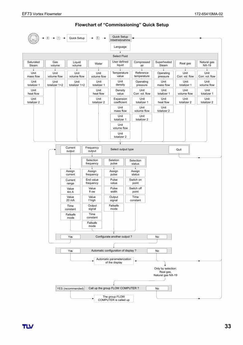
7.2.2 “Commissioning” Quick Setup
The “Commissioning” Quick Setup guides you systematically through all the major functions of the device that have to be configured for standard measuring operation. A flowchart of the “Commissioning” Quick Setup is provided on the next page.
Note!
EF73 Vortex Flowmeter 172-65410MA-02
33
Flowchart of “Commissioning” Quick Setup
++ +E EEsc
Quick Setup
Language
Select Fluid
SaturatedSteam
Unitmass flow
Unittotalizer 1
Unitheat flow
Unittotalizer 2
Quick SetupInbetriebnahme
Unitmass flow
Unitvolume flow
Unittotalizer 1
Unittotalizer 1
Unitheat flow
Unittotalizer 2
Unittotalizer 2
SuperheatedSteam
Real gas
Operatingpressure
UnitCorr. vol. flow
Water
Unitvolume flow
Unittotalizer 1
Unitheat flow
Unittotalizer 2
Compressedair
Referencetemperature
Operatingpressure
UnitCorr. vol. flow
Unittotalizer 1
Unitvolume flow
Unittotalizer 2
Gasvolume
Unitvolume flow
Unittotalizer 1+2
Unitvolume flow
Unittotalizer 1+2
Liquidvolume
Select output type
Assignpulse
Assignstatus
Assignfrequency
Assigncurrent
Currentrange
Seletionpulse
Configurate another output ?
Automatic configuration of display ?
Call up the group FLOW COMPUTER ?
Pulsevalue
Switch onpoint
End valuefrequency
Value4m A
Pulsewidth
Switch offpoint
Valuefl ow
Value20 mA
Outputsignal
Timeconstant
Valuef high
Timeconstant
Failsafemode
Outputsignal
Failsafemode
Timeconstant
Failsafemode
Automatic parameterizationof the display
Only by selection:Real gas,
Natural gas NX-19
The group FLOWCOMPUTER is called up
Frequencyoutput
Selectionstatus
No
No
No
QuitCurrentoutput
Selectionfrequency
Yes
Yes
User definedliquid
Temperaturevalue
Unitdensity
Densityvalue
Expansioncoefficient
Unitmass flow
Unittotalizer 1
Unitvolume flow
Unittotalizer 2
YES (recommended)
Unitvolume flow
Unittotalizer 1
Unittotalizer 2
Natural gasNX-19
UnitCorr. vol. flow
172-65410MA-02 EF73 Vortex Flowmeter
34
Note! The QUICK SETUP COMMISSIONING function is described in 8.2.3. The display returns to the QUICK SETUP COMMISSIONING cell if you press the ESC key combination (+ + - ) during interrogation. If the fluid selected is changed, the following parameters are reset to their
factory settings:
Function Group Parameter
Sytem Units → all parameters
Display → 100% Value Line 1, 100% Value Line 2
Current Output → all parameters
Frequency Output → all parameters
Process Parameter → all parameters
System Parameter → all parameters Only the output (current output or frequency output) not yet configured in
the current Quick Setup is offered for selection after the first cycle. The “YES” option appears as long as a free output is still available. “NO” is
the only option displayed when no further outputs are available. When “YES” is selected, the volume flow is assigned to line 1 of the local
display and the temperature to line 2. The SELECT FLUID function is called up. Confirm the fluid selected in this
function and configure all the subsequent functions of the FLOW COMPUTER group. Configuration is complete if group selection is displayed. You can get back to the Home position by means of the ESC key combination (+ + - ).
• Totalizer assignment depends on the fluid selected:
Selected Fluid Totalizer 1 Assignment Totalizer 2 Assignment
Saturated steam → Mass flow → Heat flow
Superheated steam → Mass flow → Heat flow
Water → Volume flow → Heat flow
Customer-spec. liquid → Mass flow → Volume flow
Compressed air → Corrected volume flow → Volume flow
Natural Gas NX-19 → Corrected volume flow → Volume flow
Gas volume → Volume flow → Volume flow
Liquid volume → Volume flow → Volume flow
Note!
EF73 Vortex Flowmeter 172-65410MA-02
35
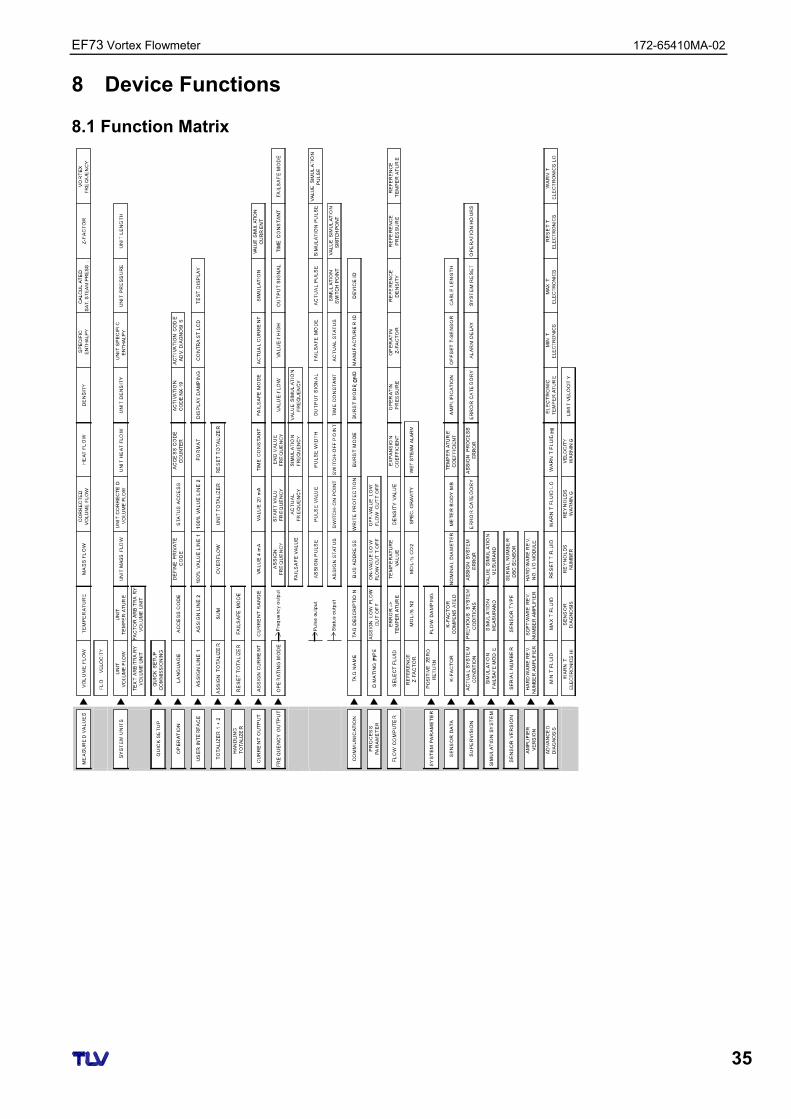
8 Device Functions
8.1 Function Matrix
172-65410MA-02 EF73 Vortex Flowmeter
36
8.2 Descriptions of Functions
8.2.1 Group MEASURED VALUES
8.2.1 Function Description MEASURED VALUES
VOLUME FLOW
The volume flow currently measured appears on the display.
Display: 5-digit floating-point number, with unit (e.g. 5.5445 dm3/min; 1.4359 m3/h; etc.)
Note! The appropriate unit is taken from the UNIT VOLUME FLOW function (8.2.2).
TEMPERATURE
The temperature currently measured appears on the display.
Display: Max. 4-digit fixed-point number, with unit and sign (e.g. -23.4 °C, 160.0 °F, 295.4 K, etc.)
Note! The appropriate unit is taken from the UNIT TEMPERATURE function (8.2.2).
MASS FLOW
Note! This value is not available unless the SATURATED STEAM, SUPERHEATED STEAM, WATER, COMPRESSED AIR, REAL GAS, NATURAL GAS NX-19 or USER-DEFINED LIQUID option was selected in the SELECT FLUID function (8.2.13). “– – – –” appears on the display if another option was selected.
The calculated mass flow appears on the display.
Display: 5-digit floating-point number, with unit (e.g. 462.87 kg/h; 731.63 lb/min; etc.)
Note! • The mass flow is calculated using the measured volume flow and the
measured temperature. • The appropriate unit is taken from the UNIT MASS FLOW function (8.2.2).
CORRECTED VOLUME FLOW
Note! This value is not available unless the WATER, USER-DEFINED LIQUID, COMPRESSED AIR, REAL GAS or NATURAL GAS NX-19 option was selected in the SELECT FLUID function (8.2.13). “– – – –” appears on the display if another option was selected.
The calculated corrected volume flow appears on the display.
Display: 5-digit floating-point number, with unit (e.g. 5.5445 Nm3/min; 1.4359 Sm3/h; etc.)
Note! • The corrected volume flow is calculated using the measured volume flow and
the measured temperature. • The appropriate unit is taken from the UNIT CORRECTED VOLUME FLOW
function (8.2.2).
EF73 Vortex Flowmeter 172-65410MA-02
37
8.2.1 Function Description MEASURED VALUES
HEAT FLOW
Note! This value is not available unless the SATURATED STEAM, SUPERHEATED STEAM or WATER option was selected in the SELECT FLUID function (8.2.13). “– – – –” appears on the display if another option was selected.
The heat flow determined appears on the display.
Display: 5-digit floating-point number, with unit, corresponds to 0.1000 – 6.000 MJ/h, (e.g. 1.2345 MJ/h, 993.5 MW, etc.)
Note! • The heat flow is determined using the fluid selected in the SELECT FLUID
function (8.2.13) and the measured temperature. • The appropriate unit is taken from the UNIT HEAT FLOW function (8.2.2).
DENSITY
Note! This function is not available unless the GAS VOLUME or LIQUID VOLUME option was selected in the SELECT FLUID function (8.2.13).
The density determined appears on the display.
Display: 5-digit floating-point number, with unit, corresponds to 0.100000 – 6.00000 kg/dm3, (e.g. 1.2345 kg/dm3, 1.0015 SG 20 °C, etc.)
Note! • The density is determined using the fluid selected in the SELECT FLUID
function (8.2.13) and the measured temperature. • The appropriate unit is taken from the UNIT DENSITY function (8.2.2).
SPECIFIC ENTHALPY
Note! This function is not available unless the SATURATED STEAM, WATER or SUPERHEATED STEAM option was selected in the SELECT FLUID function (8.2.13).
The specific enthalpy determined appears on the display.
Display: 5-digit floating-point number, with unit, (e.g. 5.1467 kJ/kg, etc.)
Note! • The enthalpy is determined using the fluid selected in the SELECT FLUID
function (8.2.13) and the measured temperature. • The appropriate unit is taken from the UNIT SPECIFIC ENTHALPY function
(8.2.2). • The enthalpy output by the device refers to the specific enthalpy of the boiling
liquid at the triple point as per IAPWS-IF97. This means that the specific internal enthalpy and the specific entropy of the boiling liquid are set to zero at the triple point. It results that the specific enthalpy is 0.611783 J/g-1 at that point.
172-65410MA-02 EF73 Vortex Flowmeter
38
8.2.1 Function Description MEASURED VALUES
CALCULATED SATURATED STEAM PRESSURE
Note! This function is not available unless the SATURATED STEAM option was selected in the SELECT FLUID function (8.2.13).
The calculated steam pressure (of the saturated steam) appears on the display.
Display: 5-digit floating-point number, with unit (e.g. 5.1467 bara, etc.)
Note! • The steam pressure of the saturated steam is determined using the fluid
selected in the SELECT FLUID function (8.2.13) and the measured temperature.
• The appropriate unit is taken from the UNIT SPECIFIC ENTHALPY function (8.2.2).
Z-FACTOR
Note! This function is not available unless the NATURAL GAS NX-19 or COMPRESSED AIR option was selected in the SELECT FLUID function (8.2.13).
• If the COMPRESSED AIR option was selected, the calculated real gas constant Z appears on the display.
• If the NATIRAL GAS NX-19 option was selected, the “Supercompressibility Factor” appears on the display.
Display: 5-digit floating-point number, (e.g. 0.9467)
Note! The real gas constant Z indicates how far a real gas differs from an ideal gas that exactly fulfills the general gas law (p x V / T = constant, Z = 1). The real gas constant approaches the value 1 the further the real gas is from its liquefaction point.
VORTEX FREQUENCY
The vortex frequency currently measured appears on the display.
Display: 5-digit floating point number, with the unit Hz, (e.g. 120.23 Hz)
Note! This function is only used for a plausibility check.
VELOCITY
The flow velocity through the device appears on the display. This is calculated from the current flow through the device and the cross-sectional area flowed through.
Display: 3-digit floating-point number, with unit
Note! The unit displayed in this function depends on the option selected in the UNIT LENGTH function (8.2.2): → “m/s” if UNIT LENGTH = “mm”; “ft/s” if UNIT LENGTH = “inch”
EF73 Vortex Flowmeter 172-65410MA-02
39
8.2.2 Group SYSTEM UNITS
8.2.2 Function Description SYSTEM UNITS
UNIT VOLUME FLOW
For selecting the unit required and displayed for the volume flow.
The unit you select here is also valid for: • Flow display • Current output (value 20 mA) • Frequency output (pulse value; value-f low, value-f high; on-value/off-value) • On-value low flow cut off • Simulation measurand
Note! The following units of time can be selected: s = second, m = minute, h = hour, d = day
Options: Metric: Cubic centimeter → cm3/time unit Cubic decimeter → dm3/time unit Cubic meter → m3/time unit Milliliter → ml/time unit Liter → l/time unit Hectoliter → hl/time unit Megaliter → Ml/time unit MEGA
US: Cubic centimeter → cc/time unit Acre foot → af/time unit Cubic foot → ft3/time unit Fluid ounce → ozf/time unit Gallon → US gal/time unit Million gallon → US Mgal/time unit Barrel (normal fluids: 31.5 gal/bbl) → US bbl/time unit NORM. Barrel (beer: 31.0 gal/bbl) → US bbl/time unit BEER Barrel (petrochemicals: 42.0 gal/bbl) → US bbl/time unit PETR. Barrel (filling tanks: 55.0 gal/bbl) → US bbl/time unit TANK
Imperial: Gallon → imp. gal/time unit Mega gallon → imp. Mgal/time unit Barrel (beer: 36.0 gal/bbl) → imp. bbl/time unit BEER Barrel (petrochemicals: 34.97 gal/bbl) → imp. bbl/time unit PETR.
Arbitrary Volume Unit: This option does not appear unless a volume unit was defined via the TEXTARBITRARY VOLUME UNIT function (8.2.2).
Note! The units for the totalizers are independent of the option selected here; they are selected in the UNIT TOTALIZER function (8.2.6).
UNIT TEMPERATURE
For selecting the unit required and displayed for the temperature.
Options: °C (Celsius) K (Kelvin) °F (Fahrenheit) R (Rankine)
Factory Setting: Depends on country (see section 12).
172-65410MA-02 EF73 Vortex Flowmeter
40
8.2.2 Function Description SYSTEM UNITS
UNIT MASS FLOW
For selecting the unit required and displayed for the calculated mass flow.
The unit you select here is also valid for: • Flow display • Current output (value 20 mA) • Frequency output (pulse value; value-f low, value-f high; on-value/off-value) • On-value low flow cut off • Simulation measurand
Note! The following units of time can be selected: s = second, m = minute, h = hour, d = day
Options: Metric: Gram → g/time unit Kilogram → kg/time unit Metric ton → t/time unit
US: Ounce → oz/time unit Pound → lb/time unit Ton → ton/time unit
UNIT CORRECTED VOLUME FLOW
For selecting the unit required and displayed for the corrected volume flow.
The unit you select here is also valid for: • Flow display • Current output (value 20 mA) • Frequency output (pulse value; value-f low, value-f high; on-value/off-value) • On-value low flow cut off • Simulation measurand
Note! The following units of time can be selected: s = second, m = minute, h = hour, d = day
Options: Metric: Norm liter → Nl/time unit Norm cubic meter → Nm3/time unit
US: Standard cubic meter → Sm3/time unit Standard cubic feet → Scf/time unit
UNIT HEAT FLOW
For selecting the unit required and displayed for the heat flow.
Note! The following units of time can be selected: s = second, m = minute, h = hour, d = day
Options: Metric: kW MW kJ/time unit MJ/time unit
GJ/time unit kcal/time unit Mcal/time unit Gcal/time unit
US: tons kBtu/time unit MBtu/time unit GBtu/time
EF73 Vortex Flowmeter 172-65410MA-02
41
8.2.2 Function Description SYSTEM UNITS
UNIT DENSITY
For selecting the unit required and displayed for the density.
Options: Metric: g/cm3 g/cc kg/dm3 kg/l kg/m3 SD 4 °C (SD = Specific Density*) SD 15 °C SD 20 °C SG 4 °C (SG = Specific Gravity) SG 15 °C SG 20 °C
US: lb/ft3 lb/US gal lb/US bbl NORM (normal fluids) lb/US bbl BEER (beer) lb/US bbl PETR. (petrochemicals) lb/US bbl TANK (filling tanks) Imperial: lb/imp. Gal lb/imp. bbl BEER (beer) lb/imp. bbl PETR. (petrochemicals)
Factory Setting: Depends on country (see section 12). * The specific density is the ratio of fluid density to water density (at water
temperature = 4, 15, 20 °C).
UNIT SPECIFIC ENTHALPY
For selecting the unit required and displayed for the specific enthalpy of saturated steam, superheated steam or water.
Options: Metric: kWh/kg kJ/kg
MJ/kg kcal/kg
US: Btu/lb
Factory Setting: Depends on country (see section 12).
UNIT PRESSURE
For selecting the unit required and displayed for the pressure.
Options: bara (bar absolute) psia (pounds per square inch absolute)
Factory Setting: bara
UNIT LENGTH
Use this function to select the unit displayed for the length of the nominal diameter in the NOMINAL DIAMETER function (8.2.16).
The unit you select here is also valid for: • The unit in which the cable length is entered (8.2.16) • The unit of velocity on the local display (8.2.1)
Options: MILLIMETER INCH
Factory Setting: Depends on country (see section 12).
172-65410MA-02 EF73 Vortex Flowmeter
42
8.2.2 Function Description SYSTEM UNITS
TEXT ARBITRARY VOLUME UNIT
Use this function to enter a text for a selectable volume flow unit. You define only the text, the associated unit of time is selected in the UNIT VOLUME FLOW function.
User Input: xxxx (max. 4 characters) Valid characters are A-Z, 0-9, +, -, decimal point, white space or underscore
Factory Setting: “– – – –” (no text)
Example: see FACTOR ARBITRARY VOLUME UNIT function.
Note! The volume unit defined in this function is offered as a possible option (arbitrary volume unit) in the UNIT VOLUME FLOW function.
FACTOR ARBITRARY VOLUME UNIT
Note! This function is not available unless a text was entered in the TEXT ARBITRARY VOLUME UNIT function.
Use this function to define a quantity factor (without time) for the selectable volume flow unit. The volume unit on which this factor is based is one liter.
User Input: 5-digit floating-point number
Factory Setting: 1
Unit: Text arbitrary volume unit / litre
8.2.3 Group QUICK SETUP
8.2.3 Function Description QUICK SETUP
QUICK SETUP COMMISSIONING
Use this function to start the Quick Setup for commissioning.
Options: NO YES
Factory Setting: NO
Note! Please refer to the a detailed description of the “Commissioning” Quick Setup menu (7.2.2).
EF73 Vortex Flowmeter 172-65410MA-02
43
8.2.4 Group OPERATION
8.2.4 Function Description OPERATION
LANGUAGE
Use this function to select the language for all texts, parameters and messages shown on the local display.
Options: ENGLISH DEUTSCH FRANCAIS ESPANOL
ITALIANO NEDERLANDS NORSK SVENSKA
SUOMI PORTUGUES POLSKI CESKI
Factory Setting: Depends on country (see section 12).
Note! If you press the ESC key ( -
+ ) at startup, the language defaults to “ENGLISH”.
ACCESS CODE
All data of the measuring system are protected against inadvertent change. Programming is disabled and the settings cannot be changed until a code is entered in this function. If you press the -
+ keys in any function, the measuring system automatically goes to this function and the prompt to enter the code appears on the display (when programming is disabled).
You can enable programming by entering the private code (factory setting = 73, see DEFINE PRIVATE CODE function).
User Input: Max. 4-digit number: 0 – 9999
Note! • The programming levels are disabled if you do not press a key within 60
seconds following a return to the HOME position. • You can also disable programming in this function by entering any number
(other than the private code). • TLV can be of assistance if you mislay your private code.
DEFINE PRIVATE CODE
Use this function to specify the private code for enabling programming.
User Input: Max. 4-digit number: 0 – 9999
Factory Setting: 73
Note! • Programming is always enabled if the code defined = 0. • Programming has to be enabled before this code can be changed. When
programming is disabled this function cannot be edited, thus preventing others from accessing your personal code.
STATUS ACCESS
The access status for the function matrix appears on the display.
Display: ACCESS CUSTOMER (parameters can be modified) LOCKED (parameters cannot be modified)
172-65410MA-02 EF73 Vortex Flowmeter
44
8.2.4 Function Description OPERATION
ACCESS CODE COUNTER
The number of times the private and service code was entered to access the device appears on the display.
Display: 7-digit number: 0 – 9999999 (delivery status: 0)
ACTIVATION CODE NX-19
Use this function to enter the activation code of the software option “Natural gas NX-19” (only relevant if the amplifier board was exchanged).
User Input: 8-digit number: 0 – 99999999
Note! If you have ordered the measuring device with this software option, the activation code for this option is also printed on the service nameplate in the cover of electronics compartment.
ACTIVATION CODE ADVANCED DIAGNOSIS
Use this function to enter the activation code of the software option “Advanced Diagnostics” (only relevant if the amplifier board was exchanged).
User Input: 8-digit number: 0 – 99999999
Note! If you have ordered the measuring device with this software option, the activation code for this option is also printed on the service nameplate in the cover of electronics compartment.
8.2.5 Group USER INTERFACE
8.2.5 Function Description USER INTERFACE
ASSIGN LINE 1
For selecting the display value for the main line (top line of the local display) that should be displayed during normal operation.
Options: OFF VOLUME FLOW VOLUME FLOW IN % TEMPERATURE MASS FLOW MASS FLOW IN %
CORRECTED VOLUME FLOW CORRECTED VOLUME FLOW IN % HEAT FLOW HEAT FLOW IN % TOTALIZER 1 TOTALIZER 2
Factory Setting: VOLUME FLOW (if no data specified or LIQUID VOLUME or GAS VOLUME specified as fluid when ordering), otherwise MASS FLOW
Note! • The appropriate unit is selected in the Group SYSTEM UNITS (8.2.2) • On the local display, totalizer 1 is displayed with “I” and totalizer 2 with “II”.
EF73 Vortex Flowmeter 172-65410MA-02
45
8.2.5 Function Description USER INTERFACE
ASSIGN LINE 2
For selecting the display value for the additional line (bottom line of the local display) that should be displayed during normal operation.
Options: OFF VOLUME FLOW VOLUME FLOW IN % BARGRAPH VOLUME FLOW IN % TEMPERATURE TOTALIZER 1 TOTALIZER 2 TAG NAME OPERATING/SYSTEM CONDITIONS MASS FLOW MASS FLOW IN % BARGRAPH MASS FLOW IN % CORRECTED VOLUME FLOW CORRECTED VOLUME FLOW IN % BARGRAPH CORRECTED VOLUME FLOW IN % HEAT FLOW HEAT FLOW IN % BARGRAPH HEAT FLOW IN %
Factory Setting: TEMPERATURE
Note! • The appropriate unit is selected in the Group SYSTEM UNITS (8.2.2) • On the local display, totalizer 1 is displayed with “I” and totalizer 2 with “II”.
100% VALUE LINE 1
Note! This function is not available unless one of the following was selected in the ASSIGN LINE 1 function. • VOLUME FLOW IN % • MASS FLOW IN % • CORRECTED VOLUME FLOW IN % • HEAT FLOW IN %
Use this function to enter the flow value that should be shown on the display as the 100% value.
User Input: 5-digit floating-point number
Factory Setting: 10 l/s (with volume flow; converted to the selected UNIT VOLUME FLOW) 10 kg/h (with mass flow; converted to the selected UNIT MASS FLOW) 10 Nm³/h (with corrected volume flow; converted to the selected UNIT
CORRECTED VOLUME FLOW) 10 kW (with heat flow; converted to the selected UNIT HEAT FLOW)
Note! The appropriate unit is taken from the Group SYSTEM UNITS (8.2.2).
172-65410MA-02 EF73 Vortex Flowmeter
46
8.2.5 Function Description USER INTERFACE
100% VALUE LINE 2
Note! This function is not available unless one of the following was selected in the ASSIGN LINE 1 function. • VOLUME FLOW IN % • MASS FLOW IN % • CORRECTED VOLUME FLOW IN % • HEAT FLOW IN % • BARGRAPH VOLUME FLOW IN % • BARGRAPH MASS FLOW IN % • BARGRAPH CORRECTED VOLUME FLOW IN % • BARGRAPH HEAT FLOW IN %
Use this function to enter the flow value that should be shown on the display as the 100% value.
User Input: 5-digit floating-point number
Factory Setting: 10 l/s (with volume flow; converted to the selected UNIT VOLUME FLOW) 10 kg/h (with mass flow; converted to the selected UNIT MASS FLOW) 10 Nm³/h (with corrected volume flow; converted to the selected UNIT
CORRECTED VOLUME FLOW) 10 kW (with heat flow; converted to the selected UNIT HEAT FLOW)
Note! The appropriate unit is taken from the Group SYSTEM UNITS (8.2.2).
FORMAT
Use this function to define the maximum number of places after the decimal point for the value displayed in the main line.
Options: XXXXX. – XXXX.X – XXX.XX – XX.XXX – X.XXXX
Display: XX.XXX
Note! • Note that this setting only affects the reading as it appears on the display; it
has no influence on the accuracy of the system's calculations. • The places after the decimal point as computed by the measuring device
cannot always be displayed, depending on this setting and the engineering unit. In these instances an arrow appears on the display between the measured value and the engineering unit (e.g. 1.2 → kg/h), indicating that the measuring system is computing with more decimal places than can be shown on the display.
EF73 Vortex Flowmeter 172-65410MA-02
47
8.2.5 Function Description USER INTERFACE
DISPLAY DAMPING
Use this function to enter a time constant defining how the display reacts to severely fluctuating flow variables, either very quickly (enter a low time constant) or with damping (enter a high time constant).
User Input: 0 – 100 s
Factory Setting: 5 s
Note! • The setting 0 seconds switches off damping. • The reaction time of the function depends on the time specified in the FLOW
DAMPING function (8.2.15).
CONTRAST LCD
Use this function to optimize the display contrast to suit local operating conditions.
User Input: 10 – 100%
Factory Setting: 50%
Note! If you press the -
+ keys simultaneously at startup, the language defaults to “ENGLISH” and the contrast is reset to the factory setting (50%).
TEST DISPLAY
Use this function to test the operability of the local display and its pixels.
Options: OFF ON
Factory Setting: OFF
Test Sequence: 1. Start the test by selecting ON.
2. All pixels of the main line and additional line are darkened for minimum 0.75 seconds.
3. The main line and additional line show an “8” in each field for minimum 0.75 seconds.
4. The main line and additional line show a “0” in each field for minimum 0.75 seconds.
5. The main line and additional line show nothing (blank display) for minimum 0.75 seconds.
6. When the test is completed, the local display returns to its initial state and the displays the option OFF.
172-65410MA-02 EF73 Vortex Flowmeter
48
8.2.6 Group TOTALIZERS 1 and 2
8.2.6 Function Description TOTALIZER
ASSIGN TOTALIZER
Use this function to assign a measured variable to the totalizer.
Options (totalizer 1 and 2): OFF VOLUME FLOW MASS FLOW CORRECTED VOLUME FLOW HEAT FLOW
Factory Setting (totalizer 1): VOLUME FLOW (if no data specified or LIQUID VOLUME or GAS VOLUME specified as fluid when ordering), otherwise MASS FLOW
Factory Setting (totalizer 2): VOLUME FLOW
Note! • If the option selected is changed, the totalizer is reset to the value “0”. • If the option selected is changed, the related unit must be adjusted to suit the
option in the UNIT TOTALIZER function! • If you select OFF, only the ASSIGN TOTALIZER function is displayed in the
Group Totalizer 1 or 2.
SUM TOTALIZER
The total for the totalizer's measured variable aggregated since measuring commenced appears on the display.
Display: Max. 7-digit floating-point number, with unit (e.g.15467.4 m3)
Note! • The totalizers' response to errors is defined in the FAILSAFE MODE function
(8.2.7) • On the local display, totalizer 1 is displayed with “I” and totalizer 2 with “II”.
OVERFLOW TOTALIZER
The total for the totalizer's overflow aggregated since measuring commenced appears on the display.
Total flow is represented by a floating-point number consisting of max. 7 digits. You can use this function to view higher numerical values (>9,999,999) as overflows. The effective quantity is thus the total of the SUM TOTALIZER function plus the value displayed in the OVERFLOW TOTALIZER function.
Example: Reading after 2 overflows: 2 E7 kg (= 20,000,000 kg) The value displayed in the SUM function = 196,845.7 kg Effective total quantity = 20,196,845.7 kg
Display: Integer with exponent, including unit (e.g. 2 E7 kg)
EF73 Vortex Flowmeter 172-65410MA-02
49
8.2.6 Function Description TOTALIZER
UNIT TOTALIZER
Use this function to define the unit for the totalizer. Depending on what is selected in the ASSIGN TOTALIZER function, only the associated units are offered for selection here.
Option Selected (ASSIGN TOTALIZER = VOLUME FLOW): Metric: 0 – 100 s Cubic centimetre → cm3 Cubic decimetre → dm3 Cubic metre → m3 Millilitre → ml Litre → l Hectolitre → hl Megalitre → Ml
Imperial: Gallon → imp. gal/...
US: Cubic centimeter → cc Acre foot → af Cubic foot → ft3 Fluid ounce → ozf Gallon → gal Million gallon → Mgal Barrel → bbl (normal fluids) Barrel → bbl (beer) Barrel → bbl (petrochemicals) Barrel → bbl (filling tanks)
Mega gallon → imp. Mgal/... Barrel (beer: 36.0 gal/bbl) → imp. bbl/... BEER Barrel (petrochemicals: 34.97 gal/bbl) → imp. bbl/... PETR.
Arbitrary volume unit: This option does not appear unless a volume unit was defined via the TEXT ARBITRARY VOLUME UNIT function (8.2.2).
Factory Setting: Depends on country (see section 12).
Option Selected (ASSIGN TOTALIZER = MASS FLOW): Metric: g kg t
US: oz lb ton
Factory Setting: Depends on country (see section 12).
Option Selected (ASSIGN TOTALIZER = CORRECTED VOLUME FLOW): Metric: Nl Nm3
US: Sm3 Scf
Factory Setting: Depends on country (see section 12).
Option Selected (ASSIGN TOTALIZER = HEAT FLOW): Metric: US: kWh MWh MJ GJ
kcal Mcal Gcal
kBtu Mbtu tonh
Factory Setting: Depends on country (see section 12).
RESET TOTALIZER
Use this function to reset the sum and the overflow of the totalizer to 0 (= RESET).
Options: NO YES
Factory Setting: NO
172-65410MA-02 EF73 Vortex Flowmeter
50
8.2.7 Group HANDLING TOTALIZERS
8.2.7 Function Description HANDLING TOTALIZER
RESET ALL TOTALIZERS
Use this function to reset the sum and the overflow of both totalizers to 0 (= RESET).
Options: NO YES
Factory Setting: NO
FAILSAFE MODE
Use this function to define the response of both totalizers to an alarm condition.
Options: STOP
The totalizer does not continue to count the flow if a fault is present. The totalizer stops at the last value before the alarm condition occurred.
ACTUAL VALUE The totalizer continues to count the flow on the basis of the current flow data. The fault is ignored.
HOLD VALUE The totalizer continues to count the flow on the basis of the last valid flow data (before the fault occurred).
Factory Setting: STOP
8.2.8 Group CURRENT OUTPUT
8.2.8 Function Description CURRENT OUTPUT
ASSIGN CURRENT
Use this function to assign a measured variable to the current output.
Options: VOLUME FLOW TEMPERATURE MASS FLOW CORRECTED VOLUME FLOW HEAT FLOW
CURRENT RANGE
Use this function to define the current range. You can configure the current output either in accordance with the NAMUR recommendation or for the values common in the United States.
Options: 4 – 20 mA HART NAMUR 4 – 20 mA HART US
EF73 Vortex Flowmeter 172-65410MA-02
51
8.2.8 Function Description CURRENT OUTPUT
VALUE 4 mA
Use this function to assign the 4 mA current a value. The value must be smaller than the value entered in the VALUE 20 mA function.
User Input: 5-digit floating-point number
VALUE 20 mA
Use this function to assign the 20 mA current a value. The value must be greater than the value entered in the VALUE 4 mA function.
User Input: 5-digit floating-point number
TIME CONSTANT
Use this function to select a time constant defining how the current output signal reacts to severely fluctuating measured variables, either very quickly (low time constant) or with damping (high time constant).
User Input: Fixed-point number: 0 – 100 s
Factory Setting: 5 s
Note! The reaction time of the function also depends on the time specified in the FLOW DAMPING function (8.2.15).
FAILSAFE MODE
The dictates of safety render it advisable to ensure that the current output assumes a predefined state in the event of a fault. Use this function to define the response of the current output to fault. The setting you select here affects only the current output. It has no effect on other outputs or the display (e.g. totalizers).
Options: MIN. CURRENT
Depends on the option selected in the CURRENT RANGE function. If the current range is: 4 – 20 mA HART NAMUR → output current = 3.6 mA 4 – 20 mA HART US → output current = 3.75 mA
MAX. CURRENT 22.6 mA
HOLD VALUE Measured value output is based on the last measured value saved before the error occurred.
ACTUAL VALUE Measured value output is based on the current flow measurement. The fault is ignored.
Factory Setting: MAX. CURRENT
172-65410MA-02 EF73 Vortex Flowmeter
52
8.2.8 Function Description CURRENT OUTPUT
ACTUAL CURRENT
The current computed actual value of the output current appears on the display.
Display: 3.60 – 22.60 mA
SIMULATION CURRENT
Use this function to activate simulation of the current output.
Options: OFF ON
Factory Setting: OFF
Note! • The notice message #611 “SIMULATION CURRENT OUTPUT” indicates that
simulation is active. • The value which should be output at the current output is defined in the
VALUE SIMULATION CURRENT function. • The measuring device continues to measure while simulation is in progress,
i.e. the current measured values are output correctly via the other outputs and the display.
Caution! The setting is not saved if the power supply fails.
VALUE SIMULATION CURRENT
Note! This function is not available unless the ON option was selected in the SIMULATION CURRENT function.
Use this function to define a selectable value (e.g. 12 mA) to be output at the current output. This value is used to test downstream devices and the measuring device itself.
User Input: Floating-point number: 3.60 – 22.60 mA
Factory Setting: 3.6 mA
Caution! The setting is not saved if the power supply fails.
Note! Simulation is started by confirming the simulation value with the E key. If the E key is pressed again afterwards, the prompt “End simulation” (NO/YES) appears. If you choose “NO”, simulation remains active and the group selection is called up. The simulation can be switched off again via the SIMULATION CURRENT function (set to “OFF”). If you choose “YES”, you end the simulation and the group selection is called up.
EF73 Vortex Flowmeter 172-65410MA-02
53
8.2.9 Group FREQUENCY (PULSE) OUTPUT
Note! The frequency output can also be operated as a pulse or status output.
8.2.9 Function Description FREQUENCY OUTPUT
OPERATING MODE
Use this function to specify whether the output functions as a frequency output, pulse output or status output. The functions available in this function group vary, depending on which option you select here.
Options: FREQUENCY PULSE STATUS VORTEX FREQUENCY (unscaled pulses, together with flow computer, see 4.2) PFM
Factory Setting: PULSE
Note! • If PFM is selected, the Current Output Group (see 8.2.8) is no longer
available. Current simulation is automatically activated with a simulation value of 4 mA. If the transmitter was wired for pulse-frequency modulation, the HART protocol is not available.
• If VORTEX FREQUENCY and PFM are selected, the vortex pulses are passed on directly. The low flow cut off is also taken into account.
ASSIGN FREQUENCY
Note! This function is not available unless the FREQUENCY option was selected in the OPERATING MODE function.
Use this function to assign a measured variable to the frequency output.
Options: VOLUME FLOW TEMPERATURE MASS FLOW CORRECTED VOLUME FLOW HEAT FLOW
Factory Setting: VOLUME FLOW
Note! If FREQUENCY is selected in the OPERATING MODE function and OFF is selected in this function, only the OPERATING MODE and ASSIGN FREQUENCY functions continue to be displayed in this function group.
Note!
172-65410MA-02 EF73 Vortex Flowmeter
54
8.2.9 Function Description FREQUENCY OUTPUT
START VALUE FREQUENCY
Note! This function is not available unless the FREQUENCY option was selected in the OPERATING MODE function.
Use this function to define a start (minimum) frequency for the frequency output. You specify the associated measured value of the measuring range in the VALUE-f LOW function.
User Input: 4-digit fixed-point number: 0 – 1000 Hz
Factory Setting: 0 Hz
Example: • START FREQUENCY = 0 Hz, VALUE-f LOW = 0 kg/h: i.e. a frequency of
0 Hz is output with a flow of 0 kg/h. • START FREQUENCY = 10 Hz, VALUE-f LOW = 1 kg/h: i.e. a frequency of
10 Hz is output with a flow of 1 kg/h.
END VALUE FREQUENCY
Note! This function is not available unless the FREQUENCY option was selected in the OPERATING MODE function.
Use this function to define an end (maximum) frequency for the frequency output. You specify the associated measured value of the measuring range in the VALUE-f HIGH function.
User Input: 5-digit fixed-point number: 2 – 1000 Hz
Factory Setting: 1000 Hz
Example: • END FREQUENCY = 1000 Hz, VALUE-f HIGH = 1000 kg/h: i.e. a frequency
of 1000 Hz is output with a flow of 1000 kg/h. • END FREQUENCY = 1000 Hz, VALUE-f HIGH = 3600 kg/h: i.e. a frequency
of 1000 Hz is output with a flow of 3600 kg/h.
Note! In the FREQUENCY operating mode the output signal is symmetrical (on/off ratio = 1:1).
EF73 Vortex Flowmeter 172-65410MA-02
55
8.2.9 Function Description FREQUENCY OUTPUT
VALUE-f LOW
Note! This function is not available unless the FREQUENCY option was selected in the OPERATING MODE function.
Use this function to assign a value to the start frequency. The value entered here must be smaller than the value assigned to the VALUE-f HIGH. A negative value is only permitted when TEMPERATURE is selected in the ASSIGN FREQUENCY function. You define the desired span by specifying the VALUE-f LOW and VALUE-f HIGH.
User Input: 5-digit floating-point number
Factory Setting: Depends on the option selected in the ASSIGN FREQUENCY function: – 0 UNIT VOLUME FLOW – 0 °C (converted to the selected UNIT TEMPERATURE) – 0 UNIT MASS FLOW – 0 UNIT CORRECTED VOLUME FLOW – 0 UNIT HEAT FLOW
Note! The appropriate unit is taken from the Group SYSTEM UNITS (8.2.2).
VALUE-f HIGH
Note! This function is not available unless the FREQUENCY option was selected in the OPERATING MODE function.
Use this function to assign a value to the end frequency. The value entered here must be greater than the value assigned to the VALUE-f LOW. A negative value is only permitted when TEMPERATURE is selected in the ASSIGN FREQUENCY function. You define the desired span by specifying the VALUE-f LOW and VALUE-f HIGH.
User Input: 5-digit floating-point number
Factory Setting: Depends on the option selected in the ASSIGN FREQUENCY function: – 10 l/s (converted to the selected UNIT VOLUME FLOW) – 200 °C (converted to the selected UNIT TEMPERATURE) – 10 kg/h (converted to the selected UNIT MASS FLOW) – 10 Nm3/h (converted to the selected UNIT CORRECTED VOLUME FLOW) – 10 kW (converted to the selected UNIT HEAT FLOW)
Note! The appropriate unit is taken from the Group SYSTEM UNITS (8.2.2).
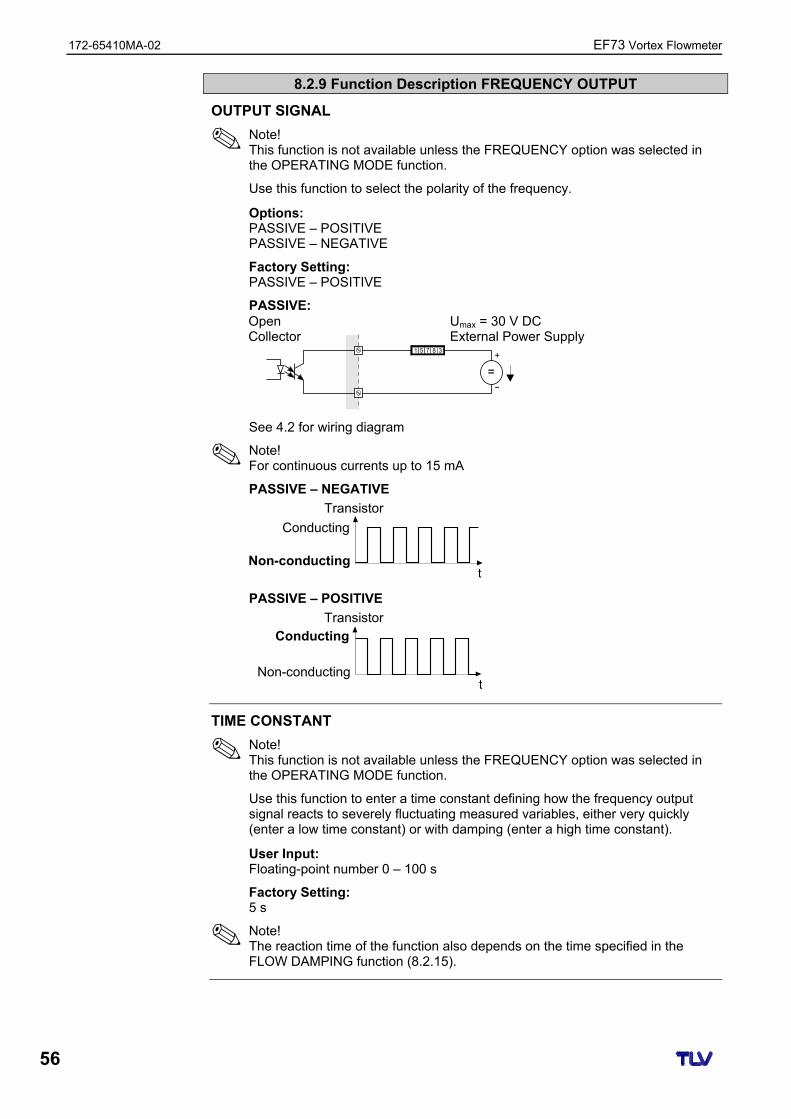
172-65410MA-02 EF73 Vortex Flowmeter
56
8.2.9 Function Description FREQUENCY OUTPUT
OUTPUT SIGNAL
Note! This function is not available unless the FREQUENCY option was selected in the OPERATING MODE function.
Use this function to select the polarity of the frequency.
Options: PASSIVE – POSITIVE PASSIVE – NEGATIVE
Factory Setting: PASSIVE – POSITIVE
PASSIVE:
1 5 8 37
+
-
=
See 4.2 for wiring diagram
Note! For continuous currents up to 15 mA
PASSIVE – NEGATIVE
Transistor
t
PASSIVE – POSITIVE
Transistor
t
TIME CONSTANT
Note! This function is not available unless the FREQUENCY option was selected in the OPERATING MODE function.
Use this function to enter a time constant defining how the frequency output signal reacts to severely fluctuating measured variables, either very quickly (enter a low time constant) or with damping (enter a high time constant).
User Input: Floating-point number 0 – 100 s
Factory Setting: 5 s
Note! The reaction time of the function also depends on the time specified in the FLOW DAMPING function (8.2.15).
Umax = 30 V DC External Power Supply
Open Collector
Non-conducting
Non-conducting
Conducting
Conducting
EF73 Vortex Flowmeter 172-65410MA-02
57
8.2.9 Function Description FREQUENCY OUTPUT
FAILSAFE MODE
Note! This function is not available unless the FREQUENCY option was selected in the OPERATING MODE function.
The dictates of safety render it advisable to ensure that the frequency output assumes a predefined state in the event of a fault. Use this function to define this state. The setting you select here affects only the frequency output. It has no effect on other outputs or the display (e.g. totalizers).
Options: FALLBACK VALUE
0 Hz is output.
FAILSAFE VALUE The frequency specified in the FAILSAFE VALUE function is output.
HOLD VALUE Measured value output is based on the last measured value saved before the error occurred.
ACTUAL VALUE Measured value output is based on the current flow measurement. The fault is ignored.
Factory Setting: FALLBACK VALUE
FAILSAFE VALUE
Note! This function is not available unless the FREQUENCY option was selected in the OPERATING MODE function and FAILSAFE VALUE was selected in the FAILSAFE MODE function.
Use this function to define the frequency that the measuring device outputs in the event of an error.
User Input: Max. 4-digit number: 0 – 1250 Hz
Factory Setting: 1250 Hz
ACTUAL FREQUENCY
Note! This function is not available unless the FREQUENCY option was selected in the OPERATING MODE function.
The computed actual value of the output frequency appears on the display.
Display: 0 – 1250 Hz
172-65410MA-02 EF73 Vortex Flowmeter
58
8.2.9 Function Description FREQUENCY OUTPUT
SIMULATION FREQUENCY
Note! This function is not available unless the FREQUENCY option was selected in the OPERATING MODE function.
Use this function to activate simulation of the frequency output.
Options: OFF ON
Factory Setting: OFF
Note! • The notice message #621 “SIM. FREQ. OUT.” indicates that simulation is
active. • The measuring device continues to measure while simulation is in progress,
i.e. the current measured values are output correctly via the other outputs.
Caution! The setting is not saved if the power supply fails.
VALUE SIMULATION FREQUENCY
Note! This function is not available unless the FREQUENCY option was selected in the OPERATING MODE function and ON was selected in the SIMULATION FREQUENCY function.
Use this function to define a selectable frequency value (e.g. 500 Hz) to be output at the frequency output. This value is used to test downstream devices and the measuring device itself. Simulation is started once the specified value is confirmed with the E key.
User Input: 0 – 1250 Hz
Factory Setting: 0 Hz
Note! Simulation is started by confirming the simulation value with the E key. If the E key is pressed again afterwards, the prompt “End simulation” (NO/YES) appears. If you choose “NO”, simulation remains active and the group selection is called up. The simulation can be switched off again via the SIMULATION FREQUENCY function. If you choose “YES”, you end the simulation and the group selection is called up.
Caution! The setting is not saved if the power supply fails.
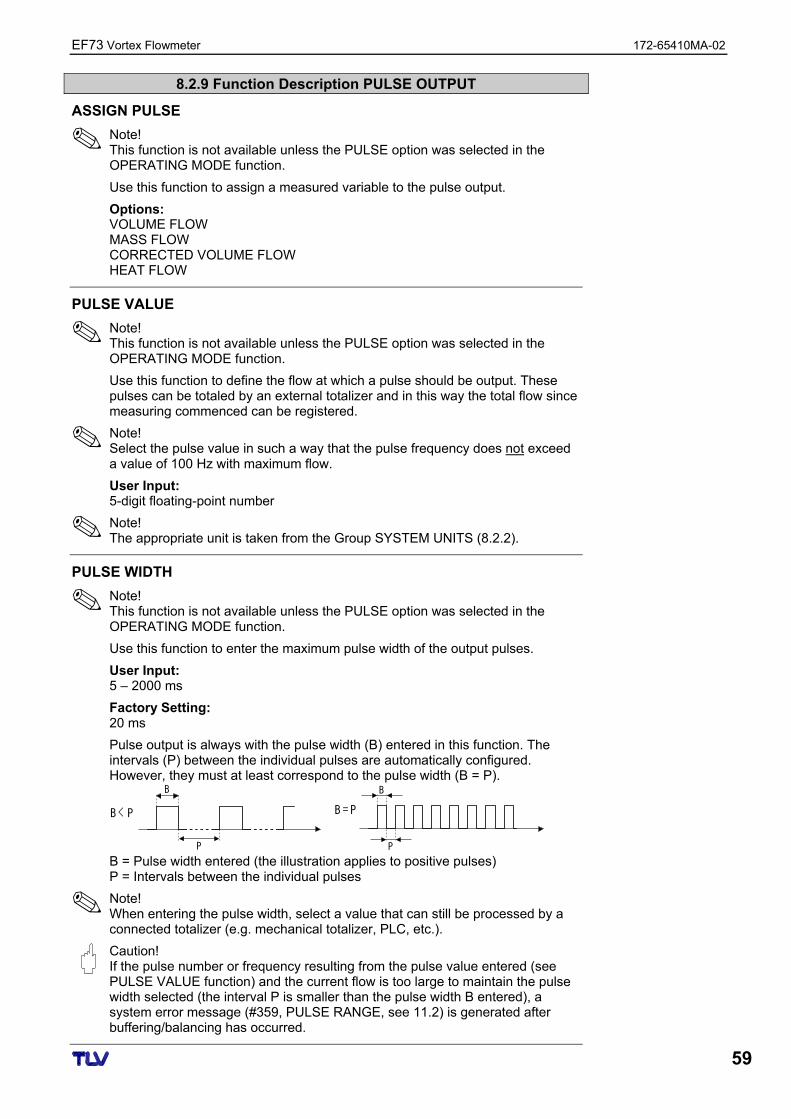
EF73 Vortex Flowmeter 172-65410MA-02
59
8.2.9 Function Description PULSE OUTPUT
ASSIGN PULSE
Note! This function is not available unless the PULSE option was selected in the OPERATING MODE function.
Use this function to assign a measured variable to the pulse output.
Options: VOLUME FLOW MASS FLOW CORRECTED VOLUME FLOW HEAT FLOW
PULSE VALUE
Note! This function is not available unless the PULSE option was selected in the OPERATING MODE function.
Use this function to define the flow at which a pulse should be output. These pulses can be totaled by an external totalizer and in this way the total flow since measuring commenced can be registered.
Note! Select the pulse value in such a way that the pulse frequency does not exceed a value of 100 Hz with maximum flow.
User Input: 5-digit floating-point number
Note! The appropriate unit is taken from the Group SYSTEM UNITS (8.2.2).
PULSE WIDTH
Note! This function is not available unless the PULSE option was selected in the OPERATING MODE function.
Use this function to enter the maximum pulse width of the output pulses.
User Input: 5 – 2000 ms
Factory Setting: 20 ms
Pulse output is always with the pulse width (B) entered in this function. The intervals (P) between the individual pulses are automatically configured. However, they must at least correspond to the pulse width (B = P).
B = P
B
PP
B
B < P
B = Pulse width entered (the illustration applies to positive pulses) P = Intervals between the individual pulses
Note! When entering the pulse width, select a value that can still be processed by a connected totalizer (e.g. mechanical totalizer, PLC, etc.).
Caution! If the pulse number or frequency resulting from the pulse value entered (see PULSE VALUE function) and the current flow is too large to maintain the pulse width selected (the interval P is smaller than the pulse width B entered), a system error message (#359, PULSE RANGE, see 11.2) is generated after buffering/balancing has occurred.
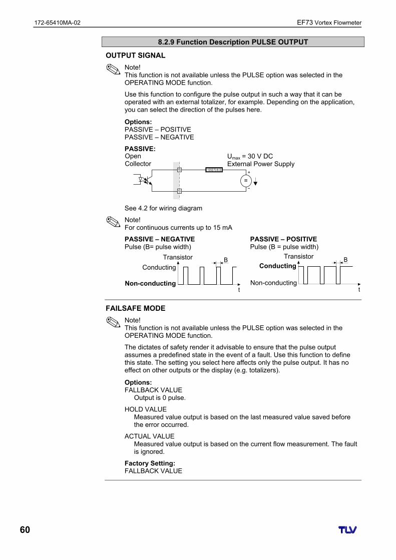
172-65410MA-02 EF73 Vortex Flowmeter
60
8.2.9 Function Description PULSE OUTPUT
OUTPUT SIGNAL
Note! This function is not available unless the PULSE option was selected in the OPERATING MODE function.
Use this function to configure the pulse output in such a way that it can be operated with an external totalizer, for example. Depending on the application, you can select the direction of the pulses here.
Options: PASSIVE – POSITIVE PASSIVE – NEGATIVE
PASSIVE:
1 5 8 37+
-
=
See 4.2 for wiring diagram
Note! For continuous currents up to 15 mA
PASSIVE – NEGATIVE Pulse (B= pulse width)
B
t
PASSIVE – POSITIVE Pulse (B = pulse width)
B
t
FAILSAFE MODE
Note! This function is not available unless the PULSE option was selected in the OPERATING MODE function.
The dictates of safety render it advisable to ensure that the pulse output assumes a predefined state in the event of a fault. Use this function to define this state. The setting you select here affects only the pulse output. It has no effect on other outputs or the display (e.g. totalizers).
Options: FALLBACK VALUE
Output is 0 pulse.
HOLD VALUE Measured value output is based on the last measured value saved before the error occurred.
ACTUAL VALUE Measured value output is based on the current flow measurement. The fault is ignored.
Factory Setting: FALLBACK VALUE
Umax = 30 V DC External Power Supply
Open Collector
Non-conducting
Conducting
Non-conducting
Conducting
Transistor Transistor
EF73 Vortex Flowmeter 172-65410MA-02
61
8.2.9 Function Description PULSE OUTPUT
ACTUAL PULSE
Note! This function is not available unless the PULSE option was selected in the OPERATING MODE function.
The computed actual value of the output frequency appears on the display.
Display: 0 – 100 pulse/second
SIMULATION PULSE
Note! This function is not available unless the PULSE option was selected in the OPERATING MODE function.
Use this function to activate simulation of the pulse output.
Options: OFF
COUNTDOWN The pulses specified in the VALUE SIMULATION PULSE function are output.
CONTINUOUSLY Pulses are continuously output with the pulse width specified in the PULSE WIDTH function. Simulation is started once the CONTINUOUSLY option is confirmed with the E key.
Note! Simulation is started by confirming the CONTINUOUSLY option with the E key. If the E key is pressed again afterwards, the prompt “End simulation” (NO/YES) appears. If you choose “NO”, simulation remains active and the group selection is called up. The simulation can be switched off again via the SIMULATION PULSE function. If you choose “YES”, you end the simulation and the group selection is called up.
Factory Setting: OFF
Note! • The notice message #631 “SIM. PULSE” indicates that simulation is active. • The on/off ratio is 1:1 for both types of simulation. • The measuring device continues to measure while simulation is in progress,
i.e. the current measured values are output correctly via the other outputs.
Caution! The setting is not saved if the power supply fails.
172-65410MA-02 EF73 Vortex Flowmeter
62
8.2.9 Function Description PULSE OUTPUT
VALUE SIMULATION PULSE
Note! This function is not available unless the COUNTDOWN option was selected in the SIMULATION PULSE function.
Use this function to specify the number of pulses (e.g. 50) that are output during the simulation. This value is used to test downstream devices and the measuring device itself. The pulses are output with the pulse width specified in the PULSE WIDTH function. The on/off ratio is 1:1.
Simulation is started once the specified value is confirmed with the E key. The display remains at 0 if the specified pulses have been output.
User Input: 0 – 10,000
Factory Setting: 0
Note! Simulation is started by confirming the simulation value with the E key. If the E key is pressed again afterwards, the prompt “End simulation” (NO/YES) appears. If you choose “NO”, simulation remains active and the group selection is called up. The simulation can be switched off again via the SIMULATION PULSE function. If you choose “YES”, you end the simulation and the group selection is called up.
Caution! The setting is not saved if the power supply fails.
EF73 Vortex Flowmeter 172-65410MA-02
63
8.2.9 Function Description STATUS OUTPUT
ASSIGN STATUS
Note! This function is not available unless the STATUS option was selected in the OPERATING MODE function.
Use this function to assign a switching function to the status output.
Options: OFF ON (operation) FAULT MESSAGE NOTICE MESSAGE FAULT MESSAGE or NOTICE MESSAGE VOLUME FLOW LIMIT VALUE TEMPERATURE LIMIT VALUE MASS FLOW LIMIT VALUE CORRECTED VOLUME FLOW LIMIT VALUE HEAT FLOW LIMIT VALUE TOTALIZER 1 LIMIT VALUE TOTALIZER 2 LIMIT VALUE
Factory Setting: FAULT MESSAGE
Note! • The status output displays quiescent current behavior, in other words the
output is closed (transistor conductive) when normal, error-free operation is in progress.
• Please pay particular attention to the illustrations and detailed information on the switching behavior of the status output (8.2.10).
• If you select OFF, the only function shown in this function group is this function (ASSIGN STATUS).
SWITCH-ON POINT
Note! This function is not available unless a limit value was selected in the ASSIGN STATUS function.
Use this function to assign a value to the switch-on point (status output pulls up). The value can be greater or less than the switch-off point. Only positive values are permissible (exception TEMPERATURE LIMIT VALUE).
User Input: 5-digit floating-point number, with unit
Factory Setting: Depends on the option selected in the ASSIGN STATUS function: – If VOLUME FLOW LIMIT VALUE was selected: see 12.1 and 12.2 – If TEMPERATURE LIMIT VALUE was selected: 180 °C
(converted to the selected UNIT TEMPERATURE) – If MASS FLOW LIMIT VALUE was selected: 10 kg/h
(converted to the selected UNIT MASS FLOW) – If CORRECTED VOLUME FLOW LIMIT VALUE was selected: 10 Nm3/h
(converted to the selected UNIT CORRECTED VOLUME FLOW) – If HEAT FLOW LIMIT VALUE was selected: 10 kW
(converted to the selected UNIT HEAT FLOW) – If TOTALIZER 1 LIMIT VALUE was selected: 0
(converted to the selected UNIT TOTALIZER 1) – If TOTALIZER 2 LIMIT VALUE was selected: 0
(converted to the selected UNIT TOTALIZER 2)
Note! The appropriate unit is taken from the Group SYSTEM UNITS (8.2.2)
172-65410MA-02 EF73 Vortex Flowmeter
64
8.2.9 Function Description STATUS OUTPUT
SWITCH-OFF POINT
Note! This function is not available unless a limit value was selected in the ASSIGN STATUS function.
Use this function to assign a value to the switch-off point (status output drops out). The value can be greater or less than the switch-on point. Only positive values are permissible (exception TEMPERATURE LIMIT VALUE).
User Input: 5-digit floating-point number, with unit
Factory Setting: Depends on the option selected in the ASSIGN STATUS function: – If VOLUME FLOW LIMIT VALUE was selected: see 12.1 and 12.2 – If TEMPERATURE LIMIT VALUE was selected: 170 °C
(converted to the selected UNIT TEMPERATURE) – If MASS FLOW LIMIT VALUE was selected: 9 kg/h
(converted to the selected UNIT MASS FLOW) – If CORRECTED VOLUME FLOW LIMIT VALUE was selected: 9 Nm3/h
(converted to the selected UNIT CORRECTED VOLUME FLOW) – If HEAT FLOW LIMIT VALUE was selected: 9 kW
(converted to the selected UNIT HEAT FLOW) – If TOTALIZER 1 LIMIT VALUE was selected: 0
(converted to the selected UNIT TOTALIZER 1) – If TOTALIZER 2 LIMIT VALUE was selected: 0
(converted to the selected UNIT TOTALIZER 2)
Note! The appropriate unit is taken from the Group SYSTEM UNITS (8.2.2)
TIME CONSTANT
Note! This function is not available unless a limit value (except TOTALIZER 1 or 2 LIMIT VALUE) was selected in the ASSIGN STATUS function.
Use this function to select a time constant defining how the measuring signal reacts to severely fluctuating measured variables, either very quickly (low time constant) or with damping (high time constant). The purpose of damping, therefore, is to prevent the status output changing state continuously in response to fluctuations in flow.
User Input: Floating-point number: 0 – 100 s
Factory Setting: 0 s
Note! The reaction time of the function also depends on the time specified in the FLOW DAMPING (8.2.15) function.
ACTUAL STATUS OUTPUT
Note! This function is not available unless the STATUS option was selected in the OPERATING MODE function.
The current status of the status output appears on the display.
User Input: NOT CONDUCTIVE CONDUCTIVE
EF73 Vortex Flowmeter 172-65410MA-02
65
8.2.9 Function Description STATUS OUTPUT
SIMULATION SWITCH POINT
Note! This function is not available unless the STATUS option was selected in the OPERATING MODE function.
Use this function to activate simulation of the status output.
User Input: OFF ON
Factory Setting: OFF
Note! • The notice message #641 “SIM. STAT. OUT.” indicates that simulation is
active. • The measuring device continues to measure while simulation is in progress,
i.e. the current measured values are output correctly via the other outputs.
Caution! The setting is not saved if the power supply fails.
VALUE SIMULATION SWITCH POINT
Note! This function is not available unless the ON option was selected in the SIMULATION SWITCH POINT function.
Use this function to define the switching behavior of the status output during the simulation. This value is used to test downstream devices and the measuring device itself.
User Input: NOT CONDUCTIVE CONDUCTIVE
Factory Setting: NOT CONDUCTIVE
Note! You can change the switching behavior of the status output during the simulation. The prompt “CONDUCTIVE” or “NOT CONDUCTIVE” appears if the + or - key is pressed. Select the desired switching behavior and start the simulation with the E key. If the E key is pressed again afterwards, the prompt “End simulation” (NO/YES) appears. If you choose “NO”, simulation remains active and the group selection is called up. The simulation can be switched off again via the SIMULATION SWITCH POINT function. If you choose “YES”, you end the simulation and the group selection is called up.
Caution! The setting is not saved if the power supply fails.
172-65410MA-02 EF73 Vortex Flowmeter
66
8.2.10 Information on the Response of the Status Output
General Information f you have configured the status output for “LIMIT VALUE”, you can specify the required switch points in the SWITCH-ON POINT and SWITCH-OFF POINT functions. When the measured variable in question reaches these predefined values, the status output switches as shown in the illustrations below. Status Output Configured for Limit Value The status output switches as soon as the current measured variable undershoots or overshoots a defined switch point. Application: monitoring flow or process-related boundary conditions. Measured Variable
t
= ON ≤ SWITCH-OFF POINT (maximum safety) = ON > SWITCH-OFF POINT (minimum safety) = Status output switched off (not conductive)
Switching Behavior of the Status Output
Function Status Open Collector
Behavior (transistor)System in operation
O Conductive
ON (operation)
System not in operation (power supply failure) X Not conductive
System OK
O Conductive
Fault Message
(System or process error) Fault → failsafe mode outputs/inputs and totalizers
X Not conductive
System OK
O Conductive
Notice Message
(System or process error) Fault → continuation of operation
X Not conductive
System OK
O Conductive
Fault Message or Notice Message
(System or process error) Fault → failsafe mode or Notice → continuation of operation
X Not conductive
Limit value not overshot or undershot Conductive
Limit Value • Volume flow • Totalizer
Limit value overshot or undershot Not conductive
EF73 Vortex Flowmeter 172-65410MA-02
67
8.2.11 Group HANDLING COMMUNICATION
8.2.11 Function Description COMMUNICATION
TAG NAME
Use this function to enter a tag name for the measuring device. You can edit and read this tag name via the local display or the HART protocol.
User Input: Max. 8-character text Permitted characters are: A-Z, 0-9, +,–, punctuation marks
Factory Setting: “– – – – – – – –” (no text)
TAG DESCRIPTION
Use this function to enter a tag description for the measuring device. You can edit and read this tag name via the local display or the HART protocol.
User Input: Max. 16-character text Permitted characters are: A-Z, 0-9, +,–, punctuation marks
Factory Setting: “– – – – – – – – – – – – – – – –” (no text)
BUS ADDRESS
Use this function to define the address for the exchange of data with the HART protocol.
User Input: 0 – 15
Factory Setting: 0
Note! A constant 4 mA current is applied with addresses 1 – 15.
WRITE PROTECTION
Use this function to check whether the measuring device can be write-accessed.
Display: OFF (execution status) = Data exchange possible ON = Data exchange disabled
Note! Write protection is activated and deactivated by means of a DIP switch on the amplifier board.
BURST MODE
Use this function to activate cyclic data exchange of the process variables selected in the BURST MODE CMD function to achieve faster communication.
Options: OFF ON
Factory Setting: OFF
172-65410MA-02 EF73 Vortex Flowmeter
68
8.2.11 Function Description COMMUNICATION
BURST MODE CMD
Use this function to activate simulation of the status output.
Options: CMD 1
Read primary measured variable (e.g. volume flow).
CMD 2 Read current and percentage of the measuring range.
CMD 3 Read current and four (previously defined) measured variables.
Factory Setting: CMD 1
MANUFACTURER ID
The manufacturer number in decimal numerical format appears on the display.
Display: 17 = (11 hex) for TLV
DEVICE ID
The instrument number in hexadecimal numerical format appears on the display.
Display: 57 = (87 dec) for EF73
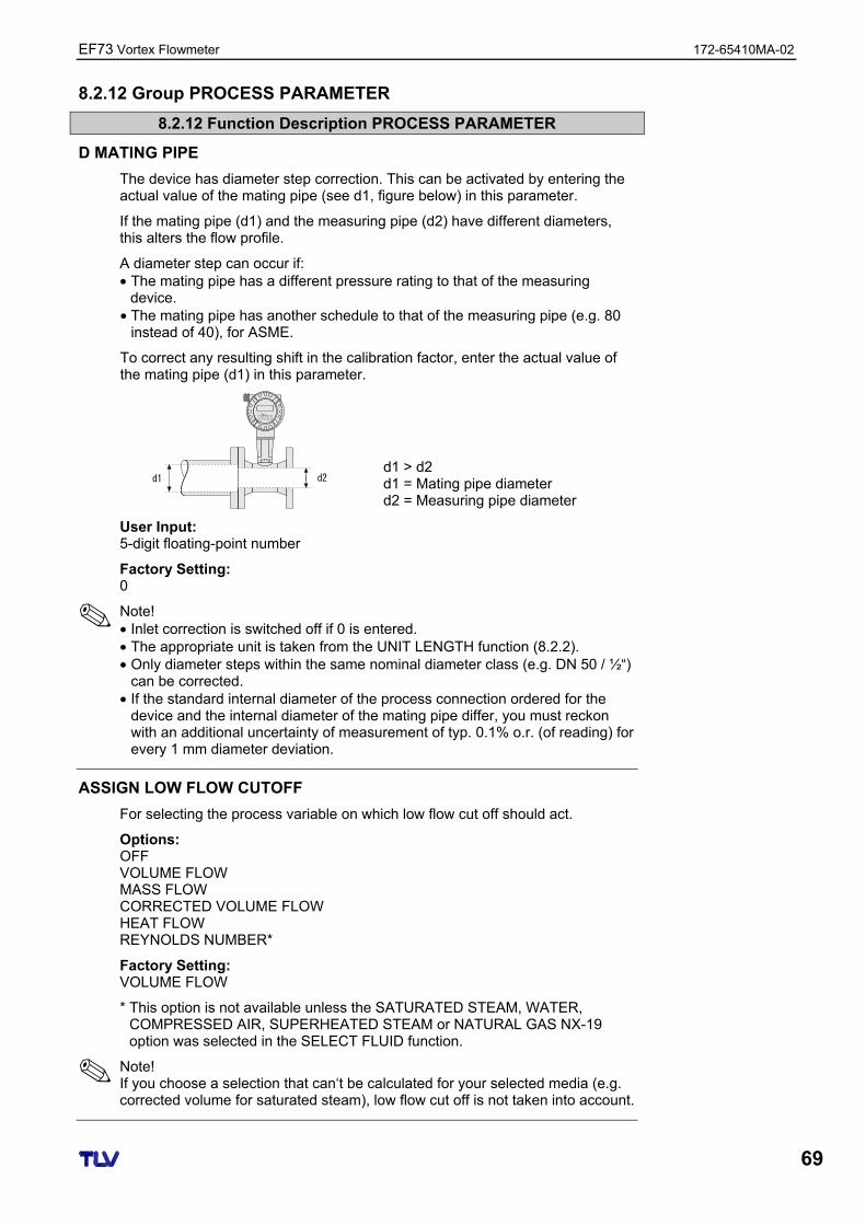
EF73 Vortex Flowmeter 172-65410MA-02
69
8.2.12 Group PROCESS PARAMETER
8.2.12 Function Description PROCESS PARAMETER
D MATING PIPE
The device has diameter step correction. This can be activated by entering the actual value of the mating pipe (see d1, figure below) in this parameter.
If the mating pipe (d1) and the measuring pipe (d2) have different diameters, this alters the flow profile.
A diameter step can occur if: • The mating pipe has a different pressure rating to that of the measuring
device. • The mating pipe has another schedule to that of the measuring pipe (e.g. 80
instead of 40), for ASME.
To correct any resulting shift in the calibration factor, enter the actual value of the mating pipe (d1) in this parameter.
d2d1
EscE- +
d1 > d2 d1 = Mating pipe diameter d2 = Measuring pipe diameter
User Input: 5-digit floating-point number
Factory Setting: 0
Note! • Inlet correction is switched off if 0 is entered. • The appropriate unit is taken from the UNIT LENGTH function (8.2.2). • Only diameter steps within the same nominal diameter class (e.g. DN 50 / ½“)
can be corrected. • If the standard internal diameter of the process connection ordered for the
device and the internal diameter of the mating pipe differ, you must reckon with an additional uncertainty of measurement of typ. 0.1% o.r. (of reading) for every 1 mm diameter deviation.
ASSIGN LOW FLOW CUTOFF
For selecting the process variable on which low flow cut off should act.
Options: OFF VOLUME FLOW MASS FLOW CORRECTED VOLUME FLOW HEAT FLOW REYNOLDS NUMBER*
Factory Setting: VOLUME FLOW
* This option is not available unless the SATURATED STEAM, WATER, COMPRESSED AIR, SUPERHEATED STEAM or NATURAL GAS NX-19 option was selected in the SELECT FLUID function.
Note! If you choose a selection that can‘t be calculated for your selected media (e.g. corrected volume for saturated steam), low flow cut off is not taken into account.
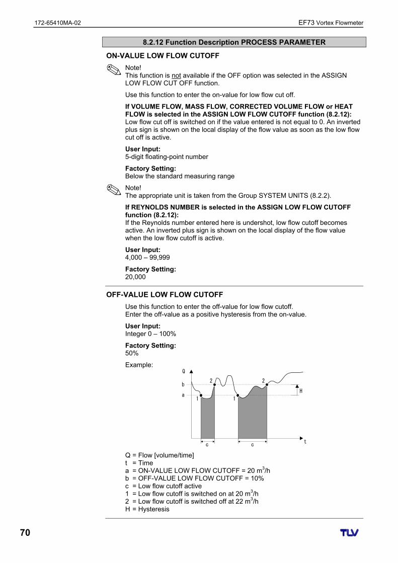
172-65410MA-02 EF73 Vortex Flowmeter
70
8.2.12 Function Description PROCESS PARAMETER
ON-VALUE LOW FLOW CUTOFF
Note! This function is not available if the OFF option was selected in the ASSIGN LOW FLOW CUT OFF function.
Use this function to enter the on-value for low flow cut off.
If VOLUME FLOW, MASS FLOW, CORRECTED VOLUME FLOW or HEAT FLOW is selected in the ASSIGN LOW FLOW CUTOFF function (8.2.12): Low flow cut off is switched on if the value entered is not equal to 0. An inverted plus sign is shown on the local display of the flow value as soon as the low flow cut off is active.
User Input: 5-digit floating-point number
Factory Setting: Below the standard measuring range
Note! The appropriate unit is taken from the Group SYSTEM UNITS (8.2.2).
If REYNOLDS NUMBER is selected in the ASSIGN LOW FLOW CUTOFF function (8.2.12): If the Reynolds number entered here is undershot, low flow cutoff becomes active. An inverted plus sign is shown on the local display of the flow value when the low flow cutoff is active.
User Input: 4,000 – 99,999
Factory Setting: 20,000
OFF-VALUE LOW FLOW CUTOFF
Use this function to enter the off-value for low flow cutoff. Enter the off-value as a positive hysteresis from the on-value.
User Input: Integer 0 – 100%
Factory Setting: 50%
Example:
1
c c
Q
t
1
2b
a
2
H
Q = Flow [volume/time] t = Time a = ON-VALUE LOW FLOW CUTOFF = 20 m3/h b = OFF-VALUE LOW FLOW CUTOFF = 10% c = Low flow cutoff active 1 = Low flow cutoff is switched on at 20 m3/h 2 = Low flow cutoff is switched off at 22 m3/h H = Hysteresis
EF73 Vortex Flowmeter 172-65410MA-02
71
8.2.13 Group FLOW COMPUTER
8.2.13 Function Description FLOW COMPUTER
SELECT FLUID
Note! We recommend you only change the fluid selected by means of the Commissioning Quick Setup (7.2.2). In the Commissioning Quick Setup, you can adjust all the relevant parameters to suit the newly selected fluid
Options: SATURATED STEAM GAS VOLUME (only volume and temperature measurement possible) LIQUID VOLUME (only volume and temperature measurement possible) WATER USER-DEFINED LIQUID COMPRESSED AIR SUPERHEATED STEAM REAL GAS (for all gases not listed here) NATURAL GAS NX-19 (only available as an option)
Information On Fluids That Can Be Selected Selected Fluid → SATURATED STEAM: Applications: Calculation of mass flow and the enthalpy it contains at the output of a steam generator or an individual consumer.
Calculated Variables: The mass flow, heat flow, density and the specific enthalpy are calculated from the measured volume flow and the measured temperature, with the aid of the saturated steam curve to the international standard IAPWS-IF97 (ASME steam data) (stored in the device).
Formula for Calculation: • Mass Flow → m = q · ρ(T) • Heat Flow → E = q · ρ(T) · hD(T)
m = Mass flow E = Heat flow q = Volume flow (measured) hD = Specific enthalpy T = Operating temperature (measured) ρ = Density (from saturated steam curve in accordance with IAPWS-IF97
(ASME), for the measured temperature) Selected Fluid → GAS VOLUME or LIQUID VOLUME: Applications: The measured volume flow and measured temperature are made available to an external flow computer. The flow can be calculated at a non-constant pressure in conjunction with an external pressure transmitter (PT).
Calculated Variables: None in this device; calculation takes place in an external flow computer.
Example of Application:
PT
EC351
SELECT FLUID continued on next page.
172-65410MA-02 EF73 Vortex Flowmeter
72
8.2.13 Function Description FLOW COMPUTER
SELECT FLUID (continued)
Selected Fluid → SUPERHEATED STEAM: Applications: Calculation of mass flow and the enthalpy it contains at the output of a steam generator or an individual consumer.
Note! The average operating pressure (p) in the steam line is needed for calculating the process variables and the measuring range limit values. The average operating pressure is not available as an input signal, but must be entered in the OPERATING PRESSURE function, i.e. exact calculation can only take place at a constant operating pressure.
Calculated Variables: The mass flow, heat flow, density and the specific enthalpy are calculated from the measured volume flow, the measured temperature and the specified operating pressure, with the aid of the saturated steam curve to the international standard IAPWS-IF97 (ASME steam data) (stored in the device).
Formula for Calculation: • Mass Flow → m = q · ρ(T,p) • Heat Flow → E = q · ρ(T,p) · hD(T,p)
m = Mass flow E = Heat flow q = Volume flow (measured) hD = Specific enthalpy T = Operating temperature (measured) p = Operating pressure (from OPERATING PRESSURE function) ρ = Density (from saturated steam curve in accordance with IAPWS-IF97
(ASME), for the measured temperature and specified pressure) Selected Fluid → WATER: Applications: Calculation of the enthalpy in a flow of water, e.g. to determine the residual heat in a heat exchanger.
Note! The average operating pressure (p) in the water line is needed for calculating the process variable. The average operating pressure is not available as an input signal, but must be entered in the OPERATING PRESSURE function, i.e. exact calculation can only take place at a constant operating pressure.
Calculated Variables: The mass flow, heat flow, density and the specific enthalpy are calculated from the measured volume flow, the measured temperature and the specified operating pressure, with the aid of the water data to the international standard IAPWS-IF97 (ASME water data) (stored in the device).
Formula for Calculation: • Mass Flow → m = q · ρ(T,p) • Heat Flow → E = q · ρ(T,p) · h(T,p) • Corrected Volume Flow → qref = q · (ρ(T,p) ÷ ρref)
m = Mass flow E = Heat flow q = Volume flow (measured) qref = Corrected volume flow h = Specific enthalpy of water T = Operating temperature (measured) p = Operating pressure (from OPERATING PRESSURE function) ρ = Density (from water data in accordance with IAPWS-IF97 (ASME), for
the measured temperature and specified pressure) ρref = Reference density (from REFERENCE DENSITY function)
SELECT FLUID continued on next page.
EF73 Vortex Flowmeter 172-65410MA-02
73
8.2.13 Function Description FLOW COMPUTER
SELECT FLUID (continued)
Selected Fluid → USER-DEFINED LIQUID: Applications: Calculation of mass flow of a user-defined liquid, e.g. a thermal oil.
Calculated Variables: The mass flow, density and the corrected volume flow are calculated from the measured volume flow and the measured temperature.
Formula for Calculation: • Mass Flow → m = q · ρ(T) • Density → ρ = ρ1(T1) ÷ (1 + βp · [T – T1]) • Corrected Volume Flow → qref = q · (ρ(T) ÷ ρref)
m = Mass flow q = Volume flow (measured) qref = Corrected volume flow T = Operating temperature (measured) T1 = Temperature at which ρ1 applies (from TEMPERATURE VALUE function)* ρ = Density ρref = Reference density (from REFERENCE DENSITY function) ρ1 = Density at which the value for T1 applies (from DENSITY VALUE function)* βp = Liquid expansion coefficient at T1 (from EXPANSION COEFFICIENT function)* * For some possible combinations of these values, refer to the table in 8.2.14.
Selected Fluid → REAL GAS (nitrogen, carbon dioxide, etc.), COMPRESSED AIR or NATURAL GAS NX-19 (option):
Applications: Calculation of mass flow and the corrected volume flow of gasses.
Note! The average operating pressure (p) in the gas line is needed for calculating the process variables and the measuring range limit values. The average operating pressure is not available as an input signal, but must be entered in the OPERATING PRESSURE function, i.e. exact calculation can only take place at a constant operating pressure.
Calculated Variables: The mass flow, density and the corrected volume flow are calculated from the measured volume flow, the measured temperature and the specified operating pressure using data stored in the device.
Note! The NX-19 equation is suitable for natural gas with a specific density between 0.554 and 0.75. The specific density describes the ratio of the reference density of the natural gas to the reference density of air (see SPECIFIC DENSITY function)
Formula for Calculation: • Mass Flow → m = q · ρ(T,p) • Density (natural gas) → ρ(T,p) = ρref · (p ÷ ρref) · (Tref ÷ T) · (Zref ÷ Z) • Corrected Volume Flow → qref = q · (ρ(T,p) ÷ ρref)
m = Mass flow q = Volume flow (measured) qref = Corrected volume flow T = Operating temperature (measured) Tref = Reference temperature (from REFERENCE TEMPERATURE function) p = Operating pressure (from OPERATING PRESSURE function) pref = Reference pressure (from REFERENCE PRESSURE function) ρ = Density* ρref = Reference density (from REFERENCE DENSITY function)* Z = Operating Z-factor (from OPERATING Z-FACTOR function)* Zref = Reference Z-factor (from REFERENCE Z-FACTOR function)* * The values from the functions are only used for real gas. For compressed air and
natural gas NX-19, the necessary data are taken from tables stored in the device.
172-65410MA-02 EF73 Vortex Flowmeter
74
8.2.13 Function Description FLOW COMPUTER
ERROR -> TEMPERATURE
Use this function to enter a temperature value for temperature measurement failure. If temperature measurement fails, the device continues to work with the temperature value entered here.
User Input: 5-digit floating-point number; with unit
Factory Setting: 20 °C (converted to the selected UNIT TEMPERATURE)
Note! The appropriate unit is taken from the UNIT TEMPERATURE function (8.2.2).
TEMPERATURE VALUE
Note! This function is not available unless the USER-DEFINED LIQUID option was selected in the SELECT FLUID function.
Use this function to enter the fluid temperature for the density specified in the DENSITY VALUE function for calculating the operating density of user-defined liquids (formula for calculation, see SELECT FLUID function).
User Input: 5-digit floating-point number
Factory Setting: 20 °C (converted to the selected UNIT TEMPERATURE)
Note! • The appropriate unit is taken from the UNIT TEMPERATURE function (8.2.2). • If the value in this function is changed, we recommend you reset the
totalizers. • A table with sample values (for the TEMPERATURE VALUE, DENSITY
VALUE and EXPANSION COEFFICIENT functions) for various fluids can be found in 8.2.14.
Caution! This setting does not change the permitted temperature range of the measuring system. Please pay particular attention to the temperature application limits specified in the product specification.
DENSITY VALUE
Note! This function is not available unless the USER-DEFINED LIQUID option was selected in the SELECT FLUID function.
Use this function to enter the density at the fluid temperature specified in the TEMPERATURE VALUE function, for calculating the operating density of user-defined liquids (formula for calculation, see SELECT FLUID function)
User Input: 5-digit floating-point number
Factory Setting: 1.0000 kg/dm3 (converted to the selected UNIT DENSITY)
Note! • The appropriate unit is taken from the UNIT DENSITY function (8.2.2). • If the value in this parameter is changed, we recommend you reset the
totalizer. • A table with sample values (for the TEMPERATURE VALUE, DENSITY
VALUE and EXPANSION COEFFICIENT functions) for various fluids can be found in 8.2.14.
EF73 Vortex Flowmeter 172-65410MA-02
75
8.2.13 Function Description FLOW COMPUTER
EXPANSION COEFFICIENT
Note! This function is not available unless the USER-DEFINED LIQUID option was selected in the SELECT FLUID function.
Use this function to enter the expansion coefficient for calculating the operating density of user-defined liquids (formula for calculation, see SELECT FLUID function).
User Input: 5-digit floating-point number, with unit (10–4 · 1/unit temperature)
Factory Setting: 2.0700 [10–4 · 1/K] (expansion coefficient for water at 20 °C)
(converted to the selected UNIT TEMPERATURE)
Note! • If the value in this function is changed, we recommend you reset the
totalizers. • If two value pairs are known for temperature and density (density ρ1 at
temperature T1 and density ρ2 at temperature T2), the expansion coefficient can be calculated as follows:
ρ1 ρ2 – 1
βp = T1 – T2 • A table with sample values (for the TEMPERATURE VALUE, DENSITY
VALUE and EXPANSION COEFFICIENT functions) for various fluids can be found in 8.2.14.
Note! The appropriate unit for temperature is taken from the UNIT TEMPERATURE function (8.2.2).
OPERATING PRESSURE
Note! This function is not available unless the WATER, COMPRESSED AIR, SUPERHEATED STEAM, REAL GAS or NATURAL GAS NX-19 option was selected in the SELECT FLUID function.
Use this function to enter the medium pressure to calculate the operating density (formula for calculation, see SELECT FLUID function).
User Input: 5-digit floating-point number; with unit
OPERATING Z-FACTOR
Note! This function is not available unless the REAL GAS option was selected in the SELECT FLUID function.
Use this function to enter the Z-factor for gas under operating conditions, i.e. for the average temperature to be expected (formula for calculation, see SELECT FLUID function)
The real gas constant Z indicates how far a real gas differs from an ideal gas that exactly fulfills the general gas law (p x V / T = constant, Z = 1). The real gas constant approaches the value 1 the further the real gas is from its liquefaction point.
User Input: 5-digit floating-point number (Entry value must be > 0)
Factory Setting: 1.0000
172-65410MA-02 EF73 Vortex Flowmeter
76
8.2.13 Function Description FLOW COMPUTER
REFERENCE DENSITY
Note! This function is not available unless the REAL GAS or USER-DEFINED LIQUID option was selected in the SELECT FLUID function.
Use this function to enter the reference density of the fluid to calculate the standard volume and the density of real gas (formula for calculation, see SELECT FLUID function), as well as the standard volume of a user-defined liquid.
User Input: 5-digit floating-point number (Entry value must be > 0)
Factory Setting: As per order, otherwise 1
Note! • The appropriate unit is taken from the UNIT DENSITY function (8.2.2). • If the value in this function is changed, we recommend you reset the
totalizers.
REFERENCE PRESSURE
Note! This function is not available unless the REAL GAS, COMPRESSED AIR or NATURAL GAS NX-19 option was selected in the SELECT FLUID function.
Use this function to enter the reference pressure of the fluid for calculating the operating density of real gas and natural gas NX-19 (formula for calculation, see SELECT FLUID function), as well as for the standard volume calculation of compressed air and natural gas NX-19.
User Input: 5-digit floating-point number (Entry value must be > 0)
Factory Setting: 1.0000
Note! The appropriate unit is taken from the UNIT PRESSURE function (8.2.2).
REFERENCE TEMPERATURE
Note! This function is not available unless the WATER, REAL GAS, COMPRESSED AIR or NATURAL GAS NX-19 option was selected in the SELECT FLUID function.
Use this function to enter the reference temperature of the fluid for calculating the operating density of real gas and natural gas NX-19 (formula for calculation, see SELECT FLUID function), as well as for the standard volume calculation of compressed air and natural gas NX-19.
User Input: 5-digit floating-point number
Factory Setting: 0 °C (converted to the selected UNIT TEMPERATURE)
Note! The appropriate unit is taken from the UNIT TEMPERATURE function (8.2.2).
Caution! This setting does not change the permitted temperature range of the measuring system. Please pay particular attention to the temperature application limits specified in the product specification.
EF73 Vortex Flowmeter 172-65410MA-02
77
8.2.13 Function Description FLOW COMPUTER
REFERENCE Z-FACTOR
Note! This function is not available unless the REAL GAS option was selected in the SELECT FLUID function.
Use this function to enter the Z-factor for gas under reference conditions. The values defined in the REFERENCE PRESSURE and REFERENCE TEMPERATURE functions apply as the reference conditions (formula for calculation, see SELECT FLUID function)
The real gas constant Z indicates how far a real gas differs from an ideal gas that exactly fulfills the general gas law (p x V / T = constant, Z = 1). The real gas constant approaches the value 1 the further the real gas is from its liquefaction point.
User Input: 5-digit floating-point number (Entry value must be > 0)
Factory Setting: 1.0000
SPECIFIC DENSITY
Note! This function is not available unless the NATURAL GAS NX-19 option was selected in the SELECT FLUID function.
Use this function to enter the specific density of natural gas (ratio of density of natural gas at reference conditions to density of air at reference conditions).
User Input: 5-digit floating-point number
Factory Setting: 0.6640
Note! The values entered in the SPECIFIC DENSITY, MOL-% N2 and MOL-% CO2 functions are interdependent. For this reason, if the value is changed in one of these functions, the values in the other functions should be adjusted accordingly.
MOL-% N2
Note! This function is not available unless the NATURAL GAS NX-19 option was selected in the SELECT FLUID function.
Use this function to enter the mol-% nitrogen in the expected natural gas mixture.
User Input: 5-digit floating-point number
Factory Setting: 0.0000%
Note! The values entered in the SPECIFIC DENSITY, MOL-% N2 and MOL-% CO2 functions are interdependent. For this reason, if the value is changed in one of these functions, the values in the other functions should be adjusted accordingly.
172-65410MA-02 EF73 Vortex Flowmeter
78
8.2.13 Function Description FLOW COMPUTER
MOL-% CO2
Note! This function is not available unless the NATURAL GAS NX-19 option was selected in the SELECT FLUID function.
Use this function to enter the mol-% carbon dioxide in the expected natural gas mixture.
User Input: 5-digit floating-point number
Factory Setting: 0.6640
Note! The values entered in the SPECIFIC DENSITY, MOL-% N2 and MOL-% CO2 functions are interdependent. For this reason, if the value is changed in one of these functions, the values in the other functions should be adjusted accordingly.
8.2.14 Sample values for the functions: TEMPERATURE VALUE,
DENSITY VALUE and EXPANSION COEFFICIENT
The calculation of the density for customer-defined liquids is better the nearer the operating temperature is to the particular value in the temperature value column. If the operating temperature deviates a lot from the value in the temperature value column, the expansion coefficient should be calculated as per the formula in 8.2.13.
Fluid (liquid)
Temperature Value(K)
Density Value (kg/m3)
Expansion Coefficient(10-4 1/K)
Air 123.15 594 18.76
Ammonia 298.15 602 25
Argon 133.15 1028 111.3
n-butane 298.15 573 20.7
Carbon Dioxide 298.15 713 106.6
Chlorine 298.15 1398 21.9
Cyclohexane 298.15 773 11.6
n-decane 298.15 728 10.2
Ethane 298.15 315 175.3
Ethylene 298.15 386 87.7
n-heptane 298.15 351 12.4
n-hexane 298.15 656 13.8
Hydrogen Chloride 298.15 796 70.9
i-butane 298.15 552 22.5
Methane 163.15 331 73.5
Nitrogen 93.15 729 75.3
n-octane 298.15 699 11.1
Oxygen 133.15 876 95.4
n-pentane 298.15 621 16.2
Propane 298.15 493 32.1
Vinyl Chloride 298.15 903 19.3
Table values from Carl L. Yaws (2001): Matheson Gas Data Book, 7th edition
For Conversion into US Imperial units: Temperature value: °F = 1.8 × K – 459.67 Density value: lb/ft3 = 0.06243 × kg/m3 Expansion coefficient: 1/°F = 1/K ÷ 1.8
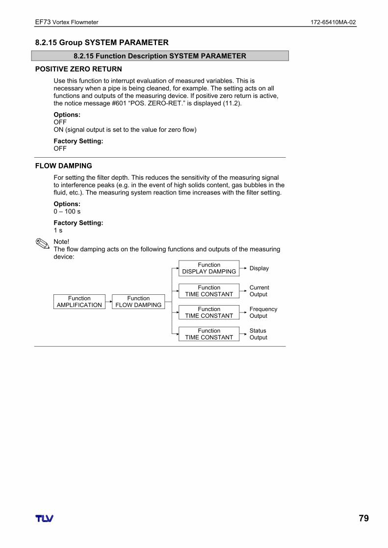
EF73 Vortex Flowmeter 172-65410MA-02
79
8.2.15 Group SYSTEM PARAMETER
8.2.15 Function Description SYSTEM PARAMETER
POSITIVE ZERO RETURN
Use this function to interrupt evaluation of measured variables. This is necessary when a pipe is being cleaned, for example. The setting acts on all functions and outputs of the measuring device. If positive zero return is active, the notice message #601 “POS. ZERO-RET.” is displayed (11.2).
Options: OFF ON (signal output is set to the value for zero flow)
Factory Setting: OFF
FLOW DAMPING
For setting the filter depth. This reduces the sensitivity of the measuring signal to interference peaks (e.g. in the event of high solids content, gas bubbles in the fluid, etc.). The measuring system reaction time increases with the filter setting.
Options: 0 – 100 s
Factory Setting: 1 s
Note! The flow damping acts on the following functions and outputs of the measuring device:
Function DISPLAY DAMPING
Display
Function
TIME CONSTANT Current Output
Function AMPLIFICATION
Function FLOW DAMPING
Function TIME CONSTANT
Frequency Output
Function TIME CONSTANT
Status Output
172-65410MA-02 EF73 Vortex Flowmeter
80
8.2.16 Group SENSOR DATA
8.2.16 Function Description SENSOR DATA
All sensor data such as the calibration factor, nominal diameter etc. are set at the factory.
Caution! Under normal circumstances these settings may not be changed because changes affect numerous functions of the entire measuring system, and the accuracy of the measuring system in particular.
Please contact your TLV representative if you have any questions on these functions.
K-FACTOR
The current calibration factor of the sensor appears on the display.
Display: e.g. 100 P/l (pulse per litre)
Note! The K-factor is also given on the nameplate, the sensor and the calibration protocol under “K-fct.”.
K-FACTOR COMPENSATED
The current compensated calibration factor of the sensor appears on the display.
The following are compensated: • The temperature-dependent expansion of the sensor (TEMPERATURE
COEFFICIENT function). • Diameter steps in the inlet of the device (D MATING PIPE function 8.2.12).
Display: e.g. 102 P/l (pulse per litre)
NOMINAL DIAMETER
The nominal diameter of the sensor appears on the display.
Display: e.g. DN 25
METER BODY TYPE MB
The type of meter body (MB) of the sensor appears on the display.
Display: e.g. 71
Note! Use this function to specify the nominal diameter and the sensor type.
TEMPERATURE COEFFICIENT
The temperature effect on the calibration factor appears on the display. Due to changes in temperature, the meter body expands differently, depending on the material. The expansion has an effect on the K-factor
Display: 4.8800×10⁻⁵ / K (stainless steel)
Caution!
EF73 Vortex Flowmeter 172-65410MA-02
81
8.2.16 Function Description SENSOR DATA
AMPLIFICATION
Devices are always optimally configured for the process conditions you specified. Under certain process conditions, however, interference signals (e.g. strong vibrations) can be suppressed or the measuring range extended by adjusting the amplification.
The amplification is configured as follows: • A larger value can be entered for the amplification if the fluid is slow-flowing,
the density is low and there are minor disturbance influences (e.g. plant vibrations).
• A smaller value can be entered for the amplification if the fluid is fast-flowing, the density is high and there are strong disturbance influences (e.g. plant vibrations).
Caution! Incorrectly configured amplification can have the following effects: • The measuring range is limited in such a way that small flows cannot be recorded
or displayed. In this instance, the value for the amplification must be increased. • Undesired interference signals are registered by the device, which means that
a flow is recorded and displayed even if the fluid is at a standstill. In this instance, the value for the amplification must be reduced.
Options: 1 – 5 (1 = smallest amplification, 5 = largest amplification)
Factory Setting: 3
OFFSET T-SENSOR
Use this function to enter the zero offset value for the temperature sensor. The value entered in this function is added to the measured temperature value.
User Input: -10 to 10 °C (-18 to 18 °F; converted to the selected UNIT TEMPERATURE)
Display: 0.00 °C
CABLE LENGTH
Use this function to enter the cable length for the remote version.
Note! • A cable length of 0 m is specified for the compact version. • If the cable supplied for connecting the device is shortened, the new cable
length must be entered here in this function. The cable length can be rounded up or off since the value entered is in steps of a meter (example: new cable length = 7.81 m → value entered = 8 m).
User Input: 0 – 30 m or 0 – 98 ft
Unit: The unit depends on the option selected in the UNIT LENGTH function (8.2.2). → “m” if UNIT LENGTH = “mm”; “ft” if UNIT LENGTH = “inch”
Factory Setting: • Compact Version: 0 m/0 ft • Remote Version: 10 m/30 ft or 30 m/98 ft (depends on specification code)
172-65410MA-02 EF73 Vortex Flowmeter
82
8.2.17 Group SUPERVISION
8.2.17 Function Description SUPERVISION
ACTUAL SYSTEM CONDITION
The current system status appears on the display.
Display: “SYSTEM OK” or the fault/notice message with the highest priority
PREVIOUS SYSTEM CONDITIONS
The last 16 fault and notice messages appear on the display.
ASSIGN SYSTEM ERROR
All system errors appear on the display. If you select a single system error you can change its error category.
Display: List of system errors
Note! • Each individual message can be selected using the + and - key. • If the E key is pressed twice, the ERROR CATEGORY function is called up. • Use the -
+ key combination or select “CANCEL” (in the system error list) to exit the function.
ERROR CATEGORY (from ASSIGN SYSTEM ERROR)
Use this function to define whether a system error triggers a notice message or a fault message. If you select “FAULT MESSAGES”, all outputs respond to an error in accordance with their defined failsafe mode.
Options: NOTICE MESSAGE (display only) FAULT MESSAGE (outputs and display)
Note! • If the E key is pressed twice, the ASSIGN SYSTEM ERROR function is
called up. • Use the -
+ key combination to exit the function.
ASSIGN PROCESS ERROR
All process errors appear on the display. If you select a single process error you can change its error category.
Display: List of system errors
Note! • Each individual message can be selected using the + and - key. • If the E key is pressed twice, the ERROR CATEGORY function is called up. • Use the -
+ key combination or select “CANCEL” (in the system error list) to exit the function.
EF73 Vortex Flowmeter 172-65410MA-02
83
8.2.17 Function Description SUPERVISION
ERROR CATEGORY (from ASSIGN PROCESS ERROR)
Use this function to define whether a system error triggers a notice message or a fault message. If you select “FAULT MESSAGES”, all outputs respond to an error in accordance with their defined failsafe mode.
Options: NOTICE MESSAGE (display only) FAULT MESSAGE (outputs and display)
Note! • If the E key is pressed twice, the ASSIGN PROCESS ERROR function is
called up. • Use the -
+ key combination to exit the function.
ALARM DELAY
Use this function to define a time span for which the criteria for an error have to be satisfied without interruption before a fault or notice message is generated. Depending on the setting and the type of error, this suppression acts on the display, the current output and the frequency output.
User Input: 0 – 100 s (in steps of one second)
Factory Setting: 0 s
Caution! If this function is used, fault and notice messages are delayed by the time corresponding to the setting before being forwarded to the higher-level controller (PCS, etc.). It is therefore imperative to check in advance whether a delay of this nature could affect the safety requirements of the process. If fault and notice messages may not be suppressed, a value of 0 seconds must be entered here.
SYSTEM RESET
Use this function to reset the measuring system.
Options: NO RESTART SYSTEM → Restart without disconnecting main power. RESET DELIVERY → Restart without disconnecting main power, the saved
settings of the delivery status (factory settings) are applied.
Factory Setting: NO
OPERATION HOURS
The hours of operation of the device appear on the display.
Display: Depends on the number of hours of operation elapsed: – If hours of operation < 10 hours → display format = 0:00:00 (hr:min:sec) – If hours of operation 10 – 10,000 hours → display format = 0000:00 (hr:min) – If hours of operation < 10,000 hours → display format = 000000 (hr)
172-65410MA-02 EF73 Vortex Flowmeter
84
8.2.18 Group SIMULATION
8.2.18 Function Description SIMULATION
SIMULATION FAILSAFE MODE
Use this function to set all inputs, outputs and the totalizer to their error-response modes, in order to check whether they respond correctly. During this time, the message #691 “SIM. FAILSAFE” appears on the display.
Options: OFF ON
Factory Setting: OFF
Caution! The setting is not saved if the power supply fails.
SIMULATION MEASURAND
Use this function to set all inputs, outputs and the totalizer to their defined flow-response modes, in order to check whether they respond correctly. During this time, the message “#692 SIM. MEASURAND” appears on the display.
Options: OFF VOLUME FLOW TEMPERATURE MASS FLOW CORRECTED VOLUME FLOW HEAT FLOW
Factory Setting: OFF
Caution! • The measuring device can only be used for measuring to a certain extent
while the simulation is in progress. • The setting is not saved if the power supply fails.
VALUE SIMULATION MEASURAND
Note! This function is not available unless the SIMULATION MEASURAND function is active.
Use this function to specify a selectable value (e.g. 12 dm³/s). This value is used to test downstream devices and the measuring device itself.
User Input: 5-digit floating-point number
Factory Setting: 0
Note! The unit depends on the option selected in the SIMULATION MEASURAND function and is taken from the related function (8.2.2).
Caution! The setting is not saved if the power supply fails.
EF73 Vortex Flowmeter 172-65410MA-02
85
8.2.19 Group SENSOR VERSION
8.2.19 Function Description SENSOR VERSION
SERIAL NUMBER
The serial number of the sensor appears on the display.
SENSOR TYPE
The sensor type appears on the display.
SERIAL NUMBER DSC SENSOR
The serial number of the DSC sensor appears on the display.
8.2.20 Group AMPLIFIER VERSION
8.2.20 Function Description AMPLIFIER VERSION
HARDWARE REVISION NUMBER AMPLIFIER
The hardware revision number of the amplifier appears on the display.
SOFTWARE REVISION NUMBER AMPLIFIER
The software revision number of the amplifier appears on the display.
Note! You can also read off the software revision number of the amplifier from the service plate in the electronics compartment cover.
HARDWARE REVISION NUMBER I/O MODULE
The hardware revision number of the I/O module appears on the display.
8.2.21 Group ADVANCED DIAGNOSIS (optional)
8.2.21 Function Description ADVANCED DIAGNOSIS
MIN T FLUID
Smallest fluid temperature measured since the last reset (RESET T FLUID function).
Display: 5-digit floating-point number, with unit and sign (e.g. 95.3 °C)
MAX T FLUID
Largest fluid temperature measured since the last reset (RESET T FLUID function).
Display: 5-digit floating-point number, with unit and sign (e.g. 218.1°C)
172-65410MA-02 EF73 Vortex Flowmeter
86
8.2.21 Function Description ADVANCED DIAGNOSIS
RESET T FLUID
Resets the values in the MIN T FLUID and MAX T FLUID functions.
Options: NO YES
Factory Setting: NO
WARN T FLUID LO
Use this function to enter the lower limit value for monitoring the fluid temperature. This limit value is used to generate a fault message that should indicate a change in the temperature of the fluid in the direction of the specification limits of the device in order to prevent device failure or prevent the process undercooling.
User Input: 5-digit floating-point number, including sign
Factory Setting: -202 °C (converted to the selected UNIT TEMPERATURE)
Note! The appropriate unit is taken from the UNIT TEMPERATURE function (8.2.2).
WARN T FLUID HI
Use this function to enter the upper limit value for monitoring the fluid temperature. This limit value is used to generate a fault message that should indicate a change in the temperature of the fluid in the direction of the specification limits of the device in order to prevent device failure or prevent the process overheating.
User Input: 5-digit floating-point number, including sign
Factory Setting: 402 °C (converted to the selected UNIT TEMPERATURE)
Note! The appropriate unit is taken from the UNIT TEMPERATURE function (8.2.2).
ELECTRONICS TEMPERATURE
The temperature on the electronics board currently measured appears on the display.
Display: 4-digit floating-point number, with unit and sign (e.g. -23.5 °C)
MIN T ELECTRONICS
Smallest electronics board temperature measured since the last reset (RESET T ELECTRONICS function).
Display: 5-digit floating-point number, including unit and sign. (e.g. 20.2 °C)
EF73 Vortex Flowmeter 172-65410MA-02
87
8.2.21 Function Description ADVANCED DIAGNOSIS
MAX T ELECTRONICS
Largest electronics board temperature measured since the last reset (RESET T ELECTRONICS function).
Display: 5-digit floating-point number, including unit and sign (e.g. 65.3 °C)
RESET T ELECTRONICS
Resets the values in the MIN T ELECTRONICS and MAX T ELECTRONICS functions.
Options: NO YES
Factory Setting: NO
WARN T ELECTRONICS LO
Use this function to enter the lower limit value for monitoring the temperature on the electronics board. This limit value is used to generate a fault message that should indicate a change in the temperature in the direction of the specification limits of the device in order to prevent device failure.
User Input: 5-digit floating-point number, including sign
Factory Setting: -41 °C (converted to the selected UNIT TEMPERATURE)
Note! The appropriate unit is taken from the UNIT TEMPERATURE function (8.2.2).
WARN T ELECTRONICS HI
Use this function to enter the upper limit value for monitoring the temperature on the electronics board. This limit value is used to generate a fault message that should indicate a change in the temperature in the direction of the specification limits of the device in order to prevent device failure.
User Input: 5-digit floating-point number, including sign
Factory Setting: 86 °C (converted to the selected UNIT TEMPERATURE)
Note! The appropriate unit is taken from the UNIT TEMPERATURE function (8.2.2).
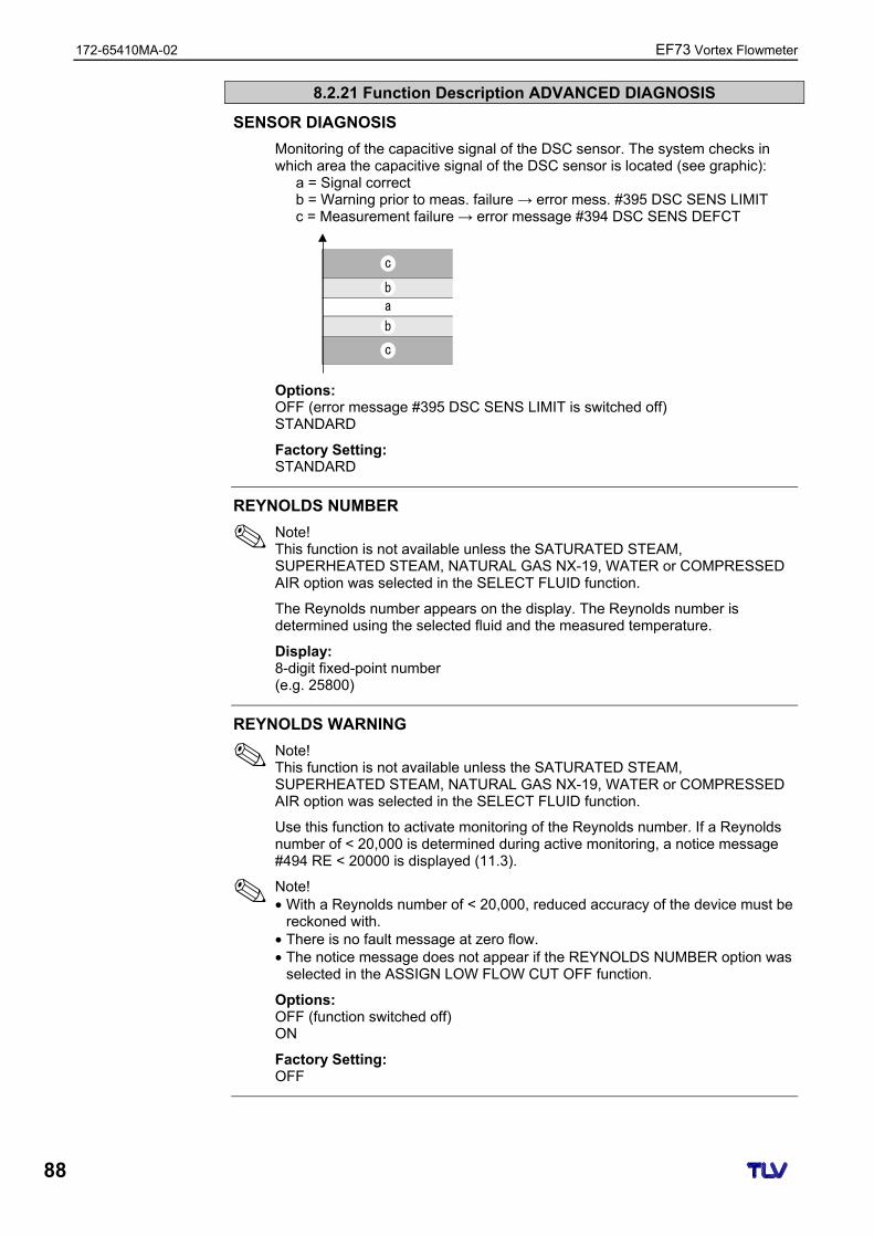
172-65410MA-02 EF73 Vortex Flowmeter
88
8.2.21 Function Description ADVANCED DIAGNOSIS
SENSOR DIAGNOSIS
Monitoring of the capacitive signal of the DSC sensor. The system checks in which area the capacitive signal of the DSC sensor is located (see graphic):
a = Signal correct b = Warning prior to meas. failure → error mess. #395 DSC SENS LIMIT c = Measurement failure → error message #394 DSC SENS DEFCT
a
b
b
c
c
Options: OFF (error message #395 DSC SENS LIMIT is switched off) STANDARD
Factory Setting: STANDARD
REYNOLDS NUMBER
Note! This function is not available unless the SATURATED STEAM, SUPERHEATED STEAM, NATURAL GAS NX-19, WATER or COMPRESSED AIR option was selected in the SELECT FLUID function.
The Reynolds number appears on the display. The Reynolds number is determined using the selected fluid and the measured temperature.
Display: 8-digit fixed-point number (e.g. 25800)
REYNOLDS WARNING
Note! This function is not available unless the SATURATED STEAM, SUPERHEATED STEAM, NATURAL GAS NX-19, WATER or COMPRESSED AIR option was selected in the SELECT FLUID function.
Use this function to activate monitoring of the Reynolds number. If a Reynolds number of < 20,000 is determined during active monitoring, a notice message #494 RE < 20000 is displayed (11.3).
Note! • With a Reynolds number of < 20,000, reduced accuracy of the device must be
reckoned with. • There is no fault message at zero flow. • The notice message does not appear if the REYNOLDS NUMBER option was
selected in the ASSIGN LOW FLOW CUT OFF function.
Options: OFF (function switched off) ON
Factory Setting: OFF
EF73 Vortex Flowmeter 172-65410MA-02
89
8.2.21 Function Description ADVANCED DIAGNOSIS
VELOCITY WARNING
Use this function to activate monitoring of the fluid velocity. If, during active monitoring, the fluid velocity exceeds the value for the limit velocity, a notice message is displayed.
Options: OFF (function switched off) ON
Factory Setting: OFF
LIMIT VELOCITY
Use this function to specify the maximum fluid velocity. If the specified maximum fluid velocity is overshot, the fault message #421 FLOW RANGE (11.3) is output.
User Input: 5-digit floating-point number
Factory Setting: 75 m/s (converted to the selected UNIT LENGTH)
Note! The unit depends on the option selected in the UNIT LENGTH function (8.2.2). → “m/s” if UNIT LENGTH = “mm”; “ft/s” if UNIT LENGTH = “inch”
172-65410MA-02 EF73 Vortex Flowmeter
90
9 Installing and Removing Electronics Boards
Caution! • Risk of damaging electronic components (ESD protection). Static electricity
can damage electronic components or impair their operability. Use a workplace with a grounded working surface, purpose-built for electrostatically sensitive devices!
• Use only TLV supplied parts. Procedure when installing/removing electronics boards (see Fig. 26)
1. Unscrew the cover (a) of the electronics compartment from the transmitter housing.
2. Remove the local display module (b) from the retaining rails (c).
3. Fit the local display module (b) with the left side onto the right retaining rail (c) (this secures the local display module).
4. Loosen the fixing screw (d) of the cover of the connection compartment (e) and fold down the cover.
5. Pull terminal connector (f) out of the I/O board (COM module) (q).
6. Fold up the plastic cover (g).
7. Remove the signal cable connector (h) from the ampifier board (s) and release from the cable holder (i).
8. Remove the ribbon cable connector (j) from the amplifier board (s) and release from the cable holder (k).
9. Remove the local display module (b) from the right retaining rail (c).
10. Fold down the plastic cover (g) again.
11. Release both screws (l) of the board holder (m).
12. Pull the board holder (m) out completely.
13. Press the side latches (n) of the board holder and separate the board holder (m) from the board body (o).
14. Replace the I/O board (COM module) (q): – Loosen the three fixing screws (p) of the I/O board (COM module). – Remove the I/O board (COM module) (q) from the board body (o). – Set a new I/O board (COM module) on the board body.
15. Replace the amplifier board (s): – Loosen fixing screws (r) of the amplifier board. – Remove the amplifier board (s) from the board body (o). – Set a new amplifier board on the board body.
16. Installation is the reverse of the removal procedure.
Caution!
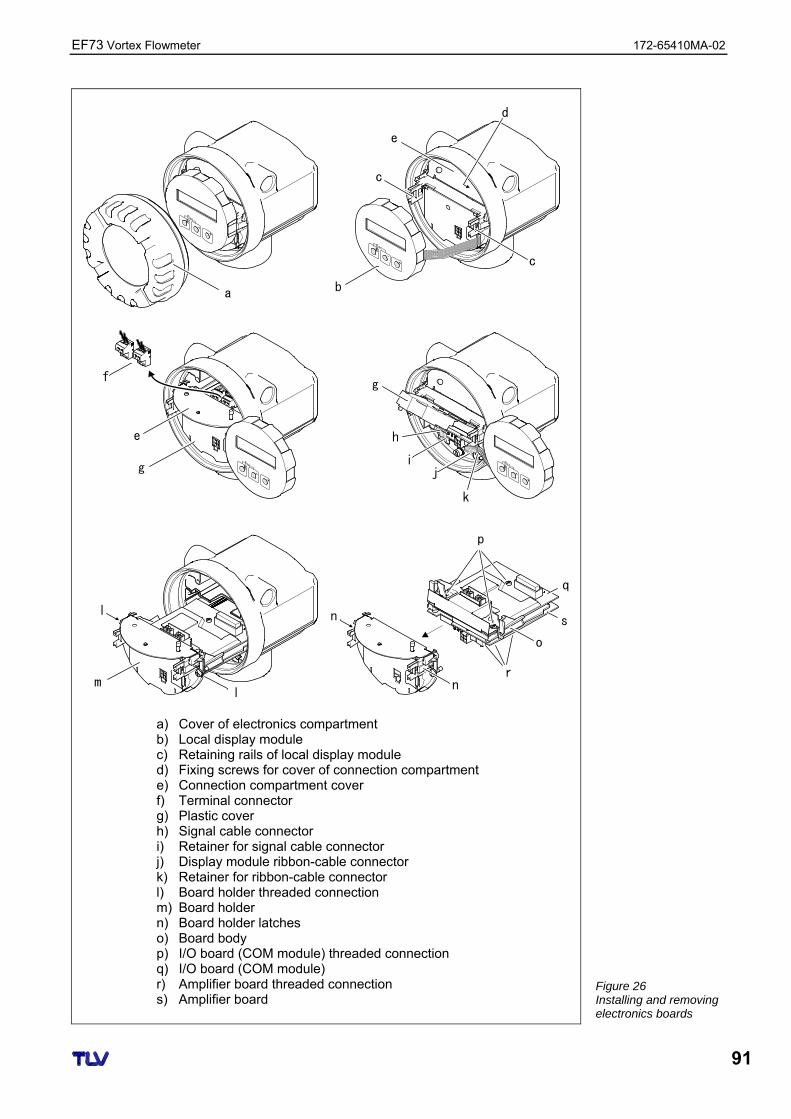
EF73 Vortex Flowmeter 172-65410MA-02
91
a
c
c
e
b
d
e
g
fg
h
j
k
i
ml
l
q
n
p
s
o
n
r
a) Cover of electronics compartment b) Local display module c) Retaining rails of local display module d) Fixing screws for cover of connection compartment e) Connection compartment cover f) Terminal connector g) Plastic cover h) Signal cable connector i) Retainer for signal cable connector j) Display module ribbon-cable connector k) Retainer for ribbon-cable connector l) Board holder threaded connection m) Board holder n) Board holder latches o) Board body p) I/O board (COM module) threaded connection q) I/O board (COM module) r) Amplifier board threaded connection s) Amplifier board
Figure 26 Installing and removing electronics boards
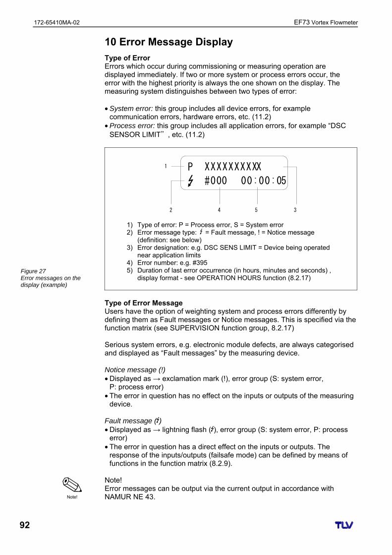
172-65410MA-02 EF73 Vortex Flowmeter
92
10 Error Message Display
Type of Error Errors which occur during commissioning or measuring operation are displayed immediately. If two or more system or process errors occur, the error with the highest priority is always the one shown on the display. The measuring system distinguishes between two types of error: • System error: this group includes all device errors, for example
communication errors, hardware errors, etc. (11.2) • Process error: this group includes all application errors, for example “DSC
SENSOR LIMIT”, etc. (11.2)
1
2 4 5 3
XXXXXXXXXX
#000 00:00:05
P
1) Type of error: P = Process error, S = System error 2) Error message type: = Fault message, ! = Notice message
(definition: see below) 3) Error designation: e.g. DSC SENS LIMIT = Device being operated
near application limits 4) Error number: e.g. #395 5) Duration of last error occurrence (in hours, minutes and seconds) ,
display format - see OPERATION HOURS function (8.2.17) Type of Error Message Users have the option of weighting system and process errors differently by defining them as Fault messages or Notice messages. This is specified via the function matrix (see SUPERVISION function group, 8.2.17) Serious system errors, e.g. electronic module defects, are always categorised and displayed as “Fault messages” by the measuring device. Notice message (!) • Displayed as → exclamation mark (!), error group (S: system error,
P: process error) • The error in question has no effect on the inputs or outputs of the measuring
device. Fault message ( ) • Displayed as → lightning flash ( ), error group (S: system error, P: process
error) • The error in question has a direct effect on the inputs or outputs. The
response of the inputs/outputs (failsafe mode) can be defined by means of functions in the function matrix (8.2.9).
Note! Error messages can be output via the current output in accordance with NAMUR NE 43.
Figure 27 Error messages on the display (example)
Note!
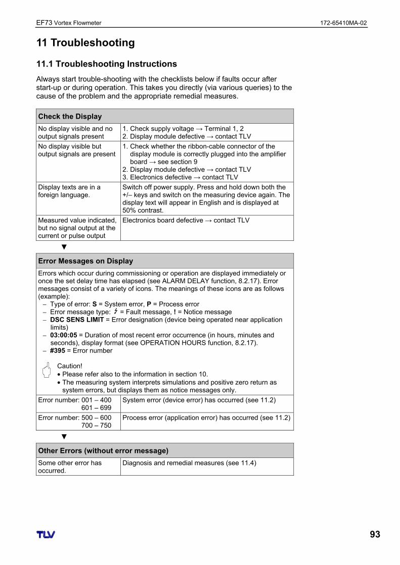
EF73 Vortex Flowmeter 172-65410MA-02
93
11 Troubleshooting
11.1 Troubleshooting Instructions
Always start trouble-shooting with the checklists below if faults occur after start-up or during operation. This takes you directly (via various queries) to the cause of the problem and the appropriate remedial measures.
Check the Display
No display visible and no output signals present
1. Check supply voltage → Terminal 1, 2 2. Display module defective → contact TLV
No display visible but output signals are present
1. Check whether the ribbon-cable connector of the display module is correctly plugged into the amplifier board → see section 9
2. Display module defective → contact TLV 3. Electronics defective → contact TLV
Display texts are in a foreign language.
Switch off power supply. Press and hold down both the +/– keys and switch on the measuring device again. The display text will appear in English and is displayed at 50% contrast.
Measured value indicated, but no signal output at the current or pulse output
Electronics board defective → contact TLV
Error Messages on Display
Errors which occur during commissioning or operation are displayed immediately or once the set delay time has elapsed (see ALARM DELAY function, 8.2.17). Error messages consist of a variety of icons. The meanings of these icons are as follows (example):
– Type of error: S = System error, P = Process error – Error message type: = Fault message, ! = Notice message – DSC SENS LIMIT = Error designation (device being operated near application
limits) – 03:00:05 = Duration of most recent error occurrence (in hours, minutes and
seconds), display format (see OPERATION HOURS function, 8.2.17). – #395 = Error number
Caution! • Please refer also to the information in section 10. • The measuring system interprets simulations and positive zero return as
system errors, but displays them as notice messages only.
Error number: 001 – 400 601 – 699
System error (device error) has occurred (see 11.2)
Error number: 500 – 600 700 – 750
Process error (application error) has occurred (see 11.2)
Other Errors (without error message)
Some other error has occurred.
Diagnosis and remedial measures (see 11.4)
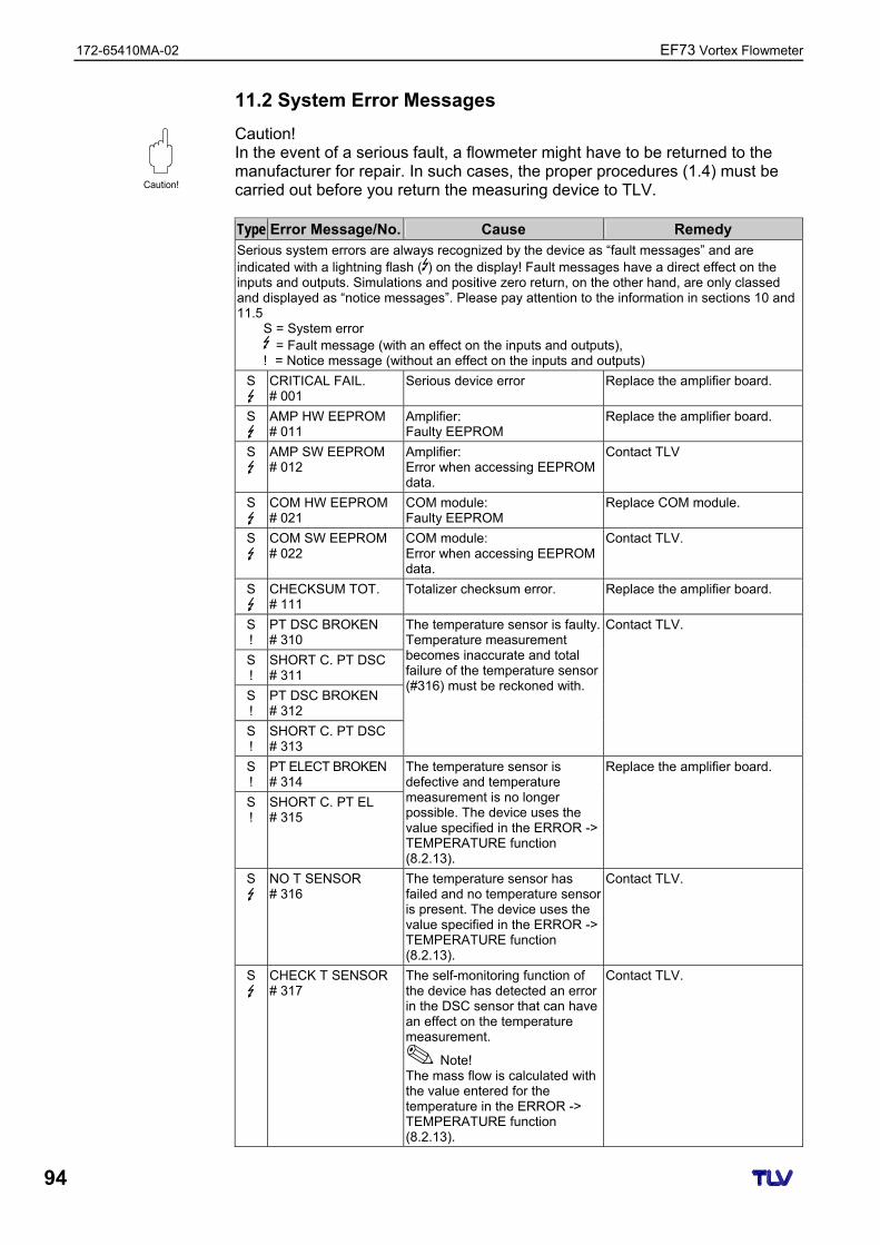
172-65410MA-02 EF73 Vortex Flowmeter
94
11.2 System Error Messages
Caution! In the event of a serious fault, a flowmeter might have to be returned to the manufacturer for repair. In such cases, the proper procedures (1.4) must be carried out before you return the measuring device to TLV. Type Error Message/No. Cause Remedy Serious system errors are always recognized by the device as “fault messages” and are indicated with a lightning flash ( ) on the display! Fault messages have a direct effect on the inputs and outputs. Simulations and positive zero return, on the other hand, are only classed and displayed as “notice messages”. Please pay attention to the information in sections 10 and 11.5
S = System error = Fault message (with an effect on the inputs and outputs),
! = Notice message (without an effect on the inputs and outputs)
S
CRITICAL FAIL. # 001
Serious device error Replace the amplifier board.
S
AMP HW EEPROM # 011
Amplifier: Faulty EEPROM
Replace the amplifier board.
S
AMP SW EEPROM # 012
Amplifier: Error when accessing EEPROM data.
Contact TLV
S
COM HW EEPROM # 021
COM module: Faulty EEPROM
Replace COM module.
S
COM SW EEPROM # 022
COM module: Error when accessing EEPROM data.
Contact TLV.
S
CHECKSUM TOT. # 111
Totalizer checksum error. Replace the amplifier board.
S !
PT DSC BROKEN # 310
S !
SHORT C. PT DSC # 311
S !
PT DSC BROKEN # 312
S !
SHORT C. PT DSC # 313
The temperature sensor is faulty. Temperature measurement becomes inaccurate and total failure of the temperature sensor (#316) must be reckoned with.
Contact TLV.
S !
PT ELECT BROKEN # 314
S !
SHORT C. PT EL # 315
The temperature sensor is defective and temperature measurement is no longer possible. The device uses the value specified in the ERROR -> TEMPERATURE function (8.2.13).
Replace the amplifier board.
S
NO T SENSOR # 316
The temperature sensor has failed and no temperature sensor is present. The device uses the value specified in the ERROR -> TEMPERATURE function (8.2.13).
Contact TLV.
S
CHECK T SENSOR # 317
The self-monitoring function of the device has detected an error in the DSC sensor that can have an effect on the temperature measurement.
Note! The mass flow is calculated with the value entered for the temperature in the ERROR -> TEMPERATURE function (8.2.13).
Contact TLV.
Caution!
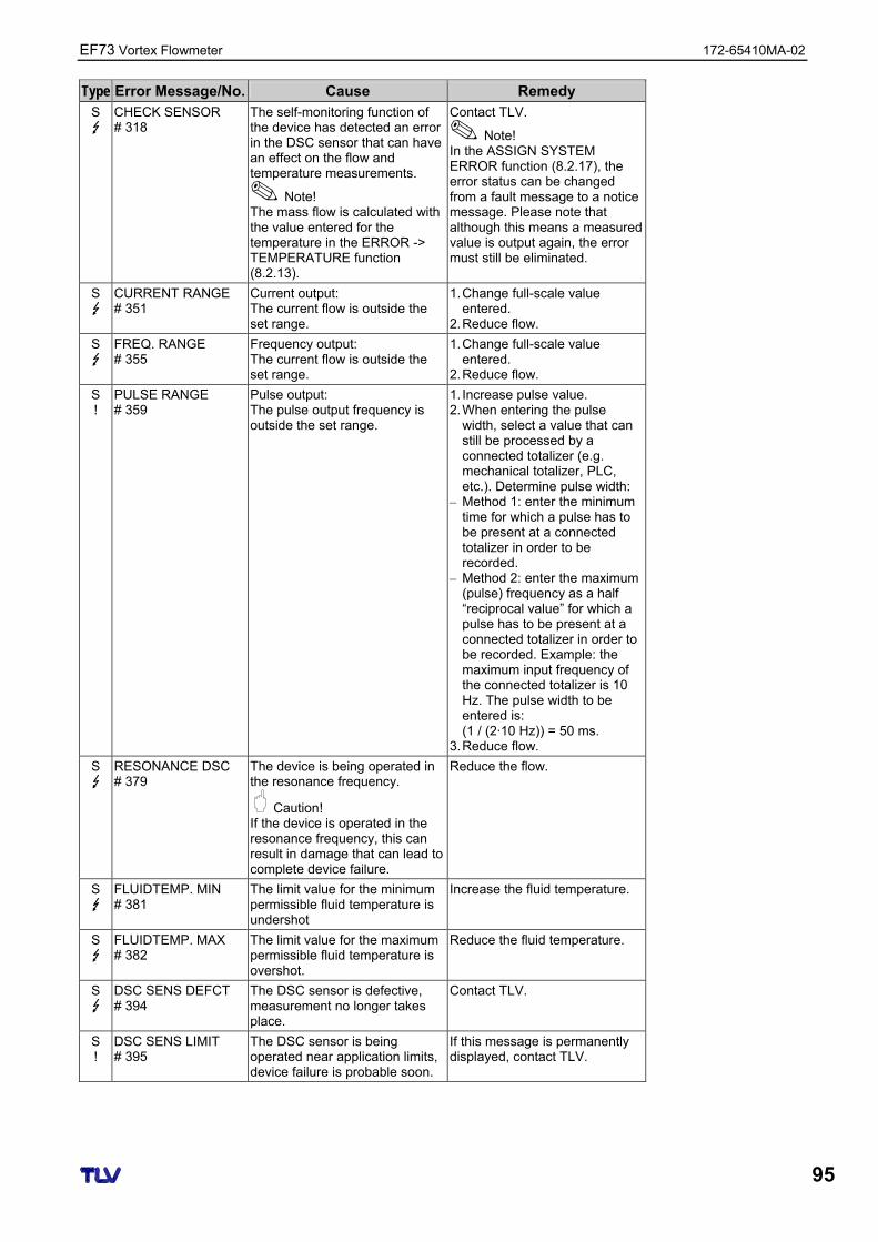
EF73 Vortex Flowmeter 172-65410MA-02
95
Type Error Message/No. Cause Remedy S
CHECK SENSOR # 318
The self-monitoring function of the device has detected an error in the DSC sensor that can have an effect on the flow and temperature measurements.
Note! The mass flow is calculated with the value entered for the temperature in the ERROR -> TEMPERATURE function (8.2.13).
Contact TLV.
Note! In the ASSIGN SYSTEM ERROR function (8.2.17), the error status can be changed from a fault message to a notice message. Please note that although this means a measured value is output again, the error must still be eliminated.
S
CURRENT RANGE # 351
Current output: The current flow is outside the set range.
1. Change full-scale value entered.
2. Reduce flow.
S
FREQ. RANGE # 355
Frequency output: The current flow is outside the set range.
1. Change full-scale value entered.
2. Reduce flow.
S !
PULSE RANGE # 359
Pulse output: The pulse output frequency is outside the set range.
1. Increase pulse value. 2. When entering the pulse
width, select a value that can still be processed by a connected totalizer (e.g. mechanical totalizer, PLC, etc.). Determine pulse width:
– Method 1: enter the minimum time for which a pulse has to be present at a connected totalizer in order to be recorded.
– Method 2: enter the maximum (pulse) frequency as a half “reciprocal value” for which a pulse has to be present at a connected totalizer in order to be recorded. Example: the maximum input frequency of the connected totalizer is 10 Hz. The pulse width to be entered is: (1 / (2·10 Hz)) = 50 ms.
3. Reduce flow.
S
RESONANCE DSC # 379
The device is being operated in the resonance frequency.
Caution! If the device is operated in the resonance frequency, this can result in damage that can lead to complete device failure.
Reduce the flow.
S
FLUIDTEMP. MIN # 381
The limit value for the minimum permissible fluid temperature is undershot
Increase the fluid temperature.
S
FLUIDTEMP. MAX # 382
The limit value for the maximum permissible fluid temperature is overshot.
Reduce the fluid temperature.
S
DSC SENS DEFCT # 394
The DSC sensor is defective, measurement no longer takes place.
Contact TLV.
S !
DSC SENS LIMIT # 395
The DSC sensor is being operated near application limits, device failure is probable soon.
If this message is permanently displayed, contact TLV.
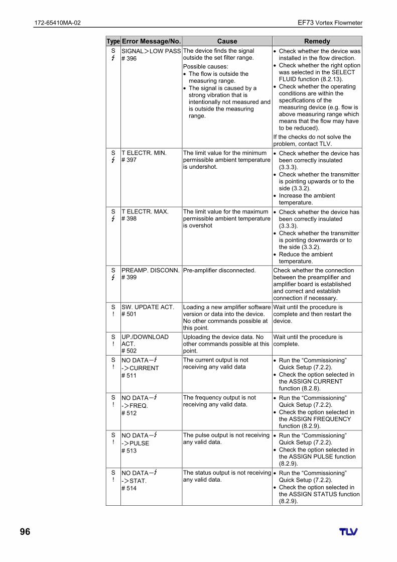
172-65410MA-02 EF73 Vortex Flowmeter
96
Type Error Message/No. Cause Remedy S
SIGNAL>LOW PASS# 396
The device finds the signal outside the set filter range.
Possible causes: • The flow is outside the
measuring range. • The signal is caused by a
strong vibration that is intentionally not measured and is outside the measuring range.
• Check whether the device was installed in the flow direction.
• Check whether the right option was selected in the SELECT FLUID function (8.2.13).
• Check whether the operating conditions are within the specifications of the measuring device (e.g. flow is above measuring range which means that the flow may have to be reduced).
If the checks do not solve the problem, contact TLV.
S
T ELECTR. MIN. # 397
The limit value for the minimum permissible ambient temperature is undershot.
• Check whether the device has been correctly insulated (3.3.3).
• Check whether the transmitter is pointing upwards or to the side (3.3.2).
• Increase the ambient temperature.
S
T ELECTR. MAX. # 398
The limit value for the maximum permissible ambient temperature is overshot
• Check whether the device has been correctly insulated (3.3.3).
• Check whether the transmitter is pointing downwards or to the side (3.3.2).
• Reduce the ambient temperature.
S
PREAMP. DISCONN.# 399
Pre-amplifier disconnected. Check whether the connection between the preamplifier and amplifier board is established and correct and establish connection if necessary.
S !
SW. UPDATE ACT. # 501
Loading a new amplifier software version or data into the device. No other commands possible at this point.
Wait until the procedure is complete and then restart the device.
S !
UP./DOWNLOAD ACT. # 502
Uploading the device data. No other commands possible at this point.
Wait until the procedure is complete.
S !
NO DATA- ->CURRENT # 511
The current output is not receiving any valid data
• Run the “Commissioning” Quick Setup (7.2.2).
• Check the option selected in the ASSIGN CURRENT function (8.2.8).
S !
NO DATA- ->FREQ. # 512
The frequency output is not receiving any valid data.
• Run the “Commissioning” Quick Setup (7.2.2).
• Check the option selected in the ASSIGN FREQUENCY function (8.2.9).
S !
NO DATA- ->PULSE # 513
The pulse output is not receiving any valid data.
• Run the “Commissioning” Quick Setup (7.2.2).
• Check the option selected in the ASSIGN PULSE function (8.2.9).
S !
NO DATA- ->STAT. # 514
The status output is not receiving any valid data.
• Run the “Commissioning” Quick Setup (7.2.2).
• Check the option selected in the ASSIGN STATUS function (8.2.9).
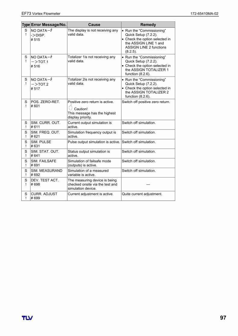
EF73 Vortex Flowmeter 172-65410MA-02
97
Type Error Message/No. Cause Remedy S !
NO DATA- ->DISP. # 515
The display is not receiving any valid data.
• Run the “Commissioning” Quick Setup (7.2.2).
• Check the option selected in the ASSIGN LINE 1 and ASSIGN LINE 2 functions (8.2.5).
S !
NO DATA- ->TOT.1 # 516
Totalizer 1is not receiving any valid data.
• Run the “Commissioning” Quick Setup (7.2.2).
• Check the option selected in the ASSIGN TOTALIZER 1 function (8.2.6).
S !
NO DATA- ->TOT.2 # 517
Totalizer 2is not receiving any valid data.
• Run the “Commissioning” Quick Setup (7.2.2).
• Check the option selected in the ASSIGN TOTALIZER 2 function (8.2.6).
S !
POS. ZERO-RET. # 601
Positive zero return is active.
Caution! This message has the highest display priority.
Switch off positive zero return.
S !
SIM. CURR. OUT. # 611
Current output simulation is active.
Switch off simulation.
S !
SIM. FREQ. OUT. # 621
Simulation frequency output is active.
Switch off simulation.
S !
SIM. PULSE # 631
Pulse output simulation is active. Switch off simulation.
S !
SIM. STAT. OUT. # 641
Status output simulation is active.
Switch off simulation.
S !
SIM. FAILSAFE # 691
Simulation of failsafe mode (outputs) is active.
Switch off simulation.
S !
SIM. MEASURAND # 692
Simulation of a measured variable is active.
Switch off simulation.
S !
DEV. TEST ACT. # 698
The measuring device is being checked onsite via the test and simulation device.
—
S !
CURR. ADJUST # 699
Current adjustment is active. Quite current adjustment.
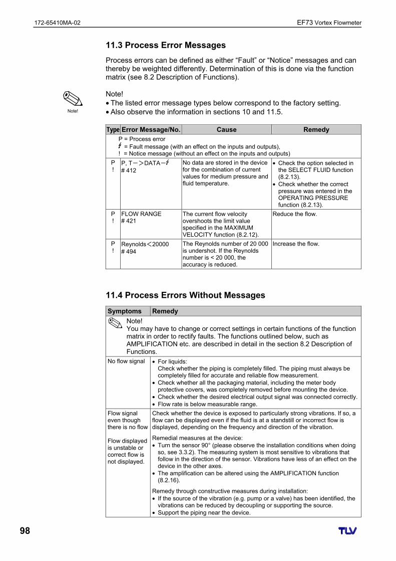
172-65410MA-02 EF73 Vortex Flowmeter
98
11.3 Process Error Messages
Process errors can be defined as either “Fault” or “Notice” messages and can thereby be weighted differently. Determination of this is done via the function matrix (see 8.2 Description of Functions). Note! • The listed error message types below correspond to the factory setting. • Also observe the information in sections 10 and 11.5. Type Error Message/No. Cause Remedy
P = Process error = Fault message (with an effect on the inputs and outputs),
! = Notice message (without an effect on the inputs and outputs)
P !
P, T->DATA- # 412
No data are stored in the device for the combination of current values for medium pressure and fluid temperature.
• Check the option selected in the SELECT FLUID function (8.2.13).
• Check whether the correct pressure was entered in the OPERATING PRESSURE function (8.2.13).
P !
FLOW RANGE # 421
The current flow velocity overshoots the limit value specified in the MAXIMUM VELOCITY function (8.2.12).
Reduce the flow.
P !
Reynolds<20000 # 494
The Reynolds number of 20 000 is undershot. If the Reynolds number is < 20 000, the accuracy is reduced.
Increase the flow.
11.4 Process Errors Without Messages
Symptoms Remedy
Note! You may have to change or correct settings in certain functions of the function matrix in order to rectify faults. The functions outlined below, such as AMPLIFICATION etc. are described in detail in the section 8.2 Description of Functions.
No flow signal • For liquids: Check whether the piping is completely filled. The piping must always be completely filled for accurate and reliable flow measurement.
• Check whether all the packaging material, including the meter body protective covers, was completely removed before mounting the device.
• Check whether the desired electrical output signal was connected correctly. • Flow rate is below measurable range.
Flow signal even though there is no flow Flow displayed is unstable or correct flow is not displayed.
Check whether the device is exposed to particularly strong vibrations. If so, a flow can be displayed even if the fluid is at a standstill or incorrect flow is displayed, depending on the frequency and direction of the vibration.
Remedial measures at the device: • Turn the sensor 90° (please observe the installation conditions when doing
so, see 3.3.2). The measuring system is most sensitive to vibrations that follow in the direction of the sensor. Vibrations have less of an effect on the device in the other axes.
• The amplification can be altered using the AMPLIFICATION function (8.2.16).
Remedy through constructive measures during installation: • If the source of the vibration (e.g. pump or a valve) has been identified, the
vibrations can be reduced by decoupling or supporting the source. • Support the piping near the device.
Note!
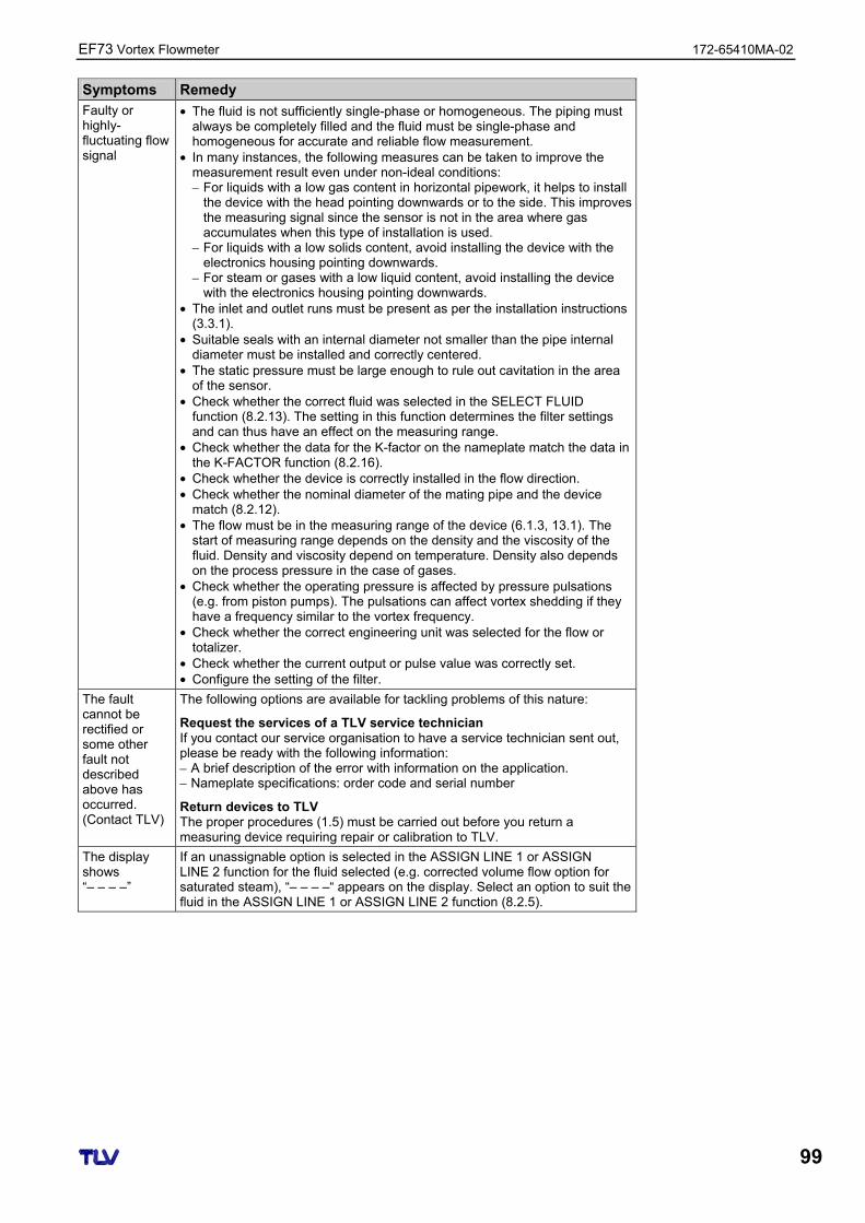
EF73 Vortex Flowmeter 172-65410MA-02
99
Symptoms Remedy Faulty or highly-fluctuating flow signal
• The fluid is not sufficiently single-phase or homogeneous. The piping must always be completely filled and the fluid must be single-phase and homogeneous for accurate and reliable flow measurement.
• In many instances, the following measures can be taken to improve the measurement result even under non-ideal conditions: – For liquids with a low gas content in horizontal pipework, it helps to install
the device with the head pointing downwards or to the side. This improves the measuring signal since the sensor is not in the area where gas accumulates when this type of installation is used.
– For liquids with a low solids content, avoid installing the device with the electronics housing pointing downwards.
– For steam or gases with a low liquid content, avoid installing the device with the electronics housing pointing downwards.
• The inlet and outlet runs must be present as per the installation instructions (3.3.1).
• Suitable seals with an internal diameter not smaller than the pipe internal diameter must be installed and correctly centered.
• The static pressure must be large enough to rule out cavitation in the area of the sensor.
• Check whether the correct fluid was selected in the SELECT FLUID function (8.2.13). The setting in this function determines the filter settings and can thus have an effect on the measuring range.
• Check whether the data for the K-factor on the nameplate match the data in the K-FACTOR function (8.2.16).
• Check whether the device is correctly installed in the flow direction. • Check whether the nominal diameter of the mating pipe and the device
match (8.2.12). • The flow must be in the measuring range of the device (6.1.3, 13.1). The
start of measuring range depends on the density and the viscosity of the fluid. Density and viscosity depend on temperature. Density also depends on the process pressure in the case of gases.
• Check whether the operating pressure is affected by pressure pulsations (e.g. from piston pumps). The pulsations can affect vortex shedding if they have a frequency similar to the vortex frequency.
• Check whether the correct engineering unit was selected for the flow or totalizer.
• Check whether the current output or pulse value was correctly set. • Configure the setting of the filter.
The fault cannot be rectified or some other fault not described above has occurred. (Contact TLV)
The following options are available for tackling problems of this nature:
Request the services of a TLV service technician If you contact our service organisation to have a service technician sent out, please be ready with the following information: – A brief description of the error with information on the application. – Nameplate specifications: order code and serial number
Return devices to TLV The proper procedures (1.5) must be carried out before you return a measuring device requiring repair or calibration to TLV.
The display shows “– – – –”
If an unassignable option is selected in the ASSIGN LINE 1 or ASSIGN LINE 2 function for the fluid selected (e.g. corrected volume flow option for saturated steam), “– – – –“ appears on the display. Select an option to suit the fluid in the ASSIGN LINE 1 or ASSIGN LINE 2 function (8.2.5).
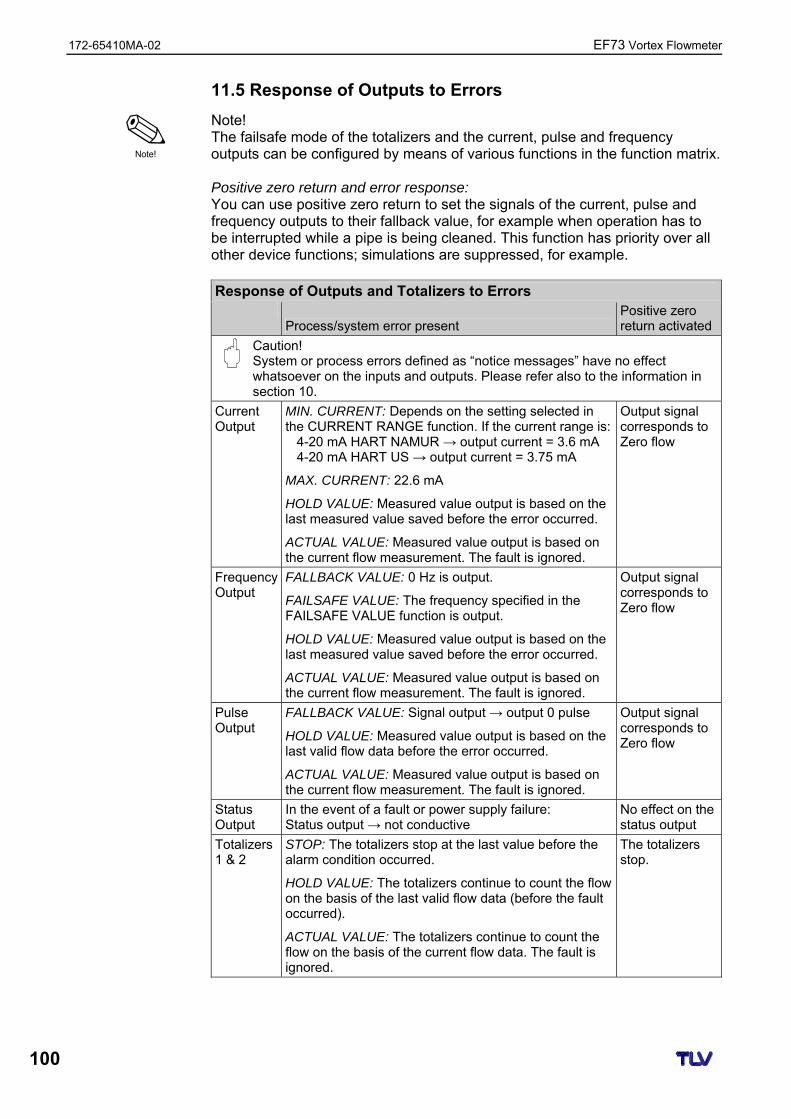
172-65410MA-02 EF73 Vortex Flowmeter
100
11.5 Response of Outputs to Errors
Note! The failsafe mode of the totalizers and the current, pulse and frequency outputs can be configured by means of various functions in the function matrix. Positive zero return and error response: You can use positive zero return to set the signals of the current, pulse and frequency outputs to their fallback value, for example when operation has to be interrupted while a pipe is being cleaned. This function has priority over all other device functions; simulations are suppressed, for example. Response of Outputs and Totalizers to Errors
Process/system error present Positive zero return activated
Caution! System or process errors defined as “notice messages” have no effect whatsoever on the inputs and outputs. Please refer also to the information in section 10.
Current Output
MIN. CURRENT: Depends on the setting selected in the CURRENT RANGE function. If the current range is:
4-20 mA HART NAMUR → output current = 3.6 mA 4-20 mA HART US → output current = 3.75 mA
MAX. CURRENT: 22.6 mA
HOLD VALUE: Measured value output is based on the last measured value saved before the error occurred.
ACTUAL VALUE: Measured value output is based on the current flow measurement. The fault is ignored.
Output signal corresponds to Zero flow
Frequency Output
FALLBACK VALUE: 0 Hz is output.
FAILSAFE VALUE: The frequency specified in the FAILSAFE VALUE function is output.
HOLD VALUE: Measured value output is based on the last measured value saved before the error occurred.
ACTUAL VALUE: Measured value output is based on the current flow measurement. The fault is ignored.
Output signal corresponds to Zero flow
Pulse Output
FALLBACK VALUE: Signal output → output 0 pulse
HOLD VALUE: Measured value output is based on the last valid flow data before the error occurred.
ACTUAL VALUE: Measured value output is based on the current flow measurement. The fault is ignored.
Output signal corresponds to Zero flow
Status Output
In the event of a fault or power supply failure: Status output → not conductive
No effect on the status output
Totalizers 1 & 2
STOP: The totalizers stop at the last value before the alarm condition occurred.
HOLD VALUE: The totalizers continue to count the flow on the basis of the last valid flow data (before the fault occurred).
ACTUAL VALUE: The totalizers continue to count the flow on the basis of the current flow data. The fault is ignored.
The totalizers stop.
Note!
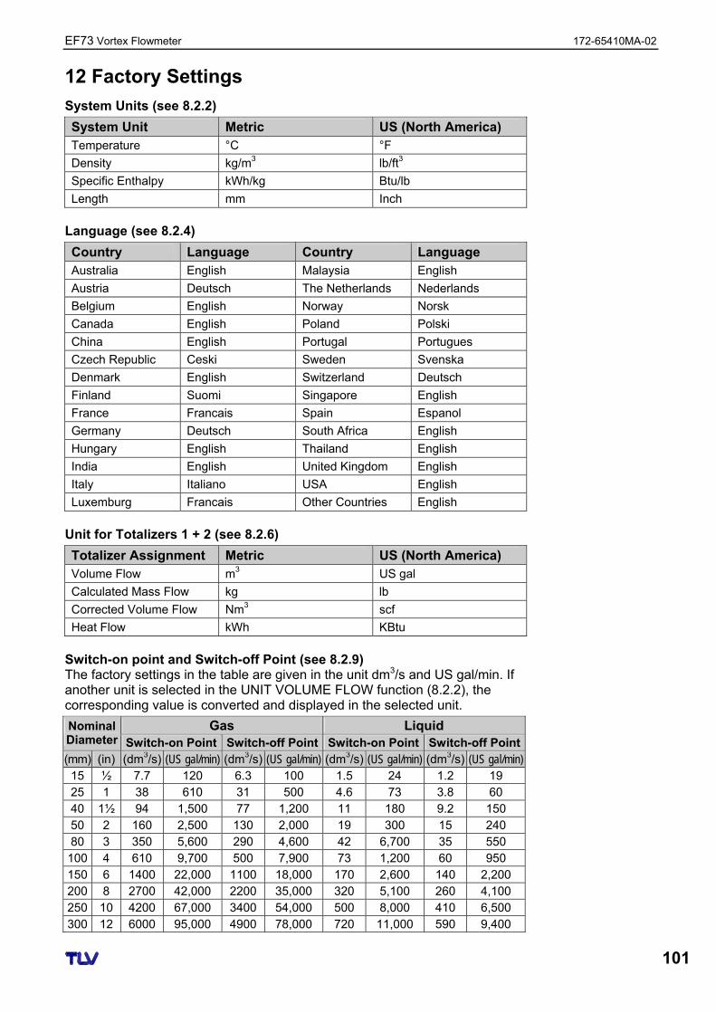
EF73 Vortex Flowmeter 172-65410MA-02
101
12 Factory Settings
System Units (see 8.2.2)
System Unit Metric US (North America) Temperature °C °F
Density kg/m3 lb/ft3
Specific Enthalpy kWh/kg Btu/lb
Length mm Inch
Language (see 8.2.4)
Country Language Country Language Australia English Malaysia English
Austria Deutsch The Netherlands Nederlands
Belgium English Norway Norsk
Canada English Poland Polski
China English Portugal Portugues
Czech Republic Ceski Sweden Svenska
Denmark English Switzerland Deutsch
Finland Suomi Singapore English
France Francais Spain Espanol
Germany Deutsch South Africa English
Hungary English Thailand English
India English United Kingdom English
Italy Italiano USA English
Luxemburg Francais Other Countries English
Unit for Totalizers 1 + 2 (see 8.2.6)
Totalizer Assignment Metric US (North America) Volume Flow m3 US gal
Calculated Mass Flow kg lb
Corrected Volume Flow Nm3 scf
Heat Flow kWh KBtu
Switch-on point and Switch-off Point (see 8.2.9) The factory settings in the table are given in the unit dm3/s and US gal/min. If another unit is selected in the UNIT VOLUME FLOW function (8.2.2), the corresponding value is converted and displayed in the selected unit.
Gas Liquid Nominal Diameter Switch-on Point Switch-off Point Switch-on Point Switch-off Point (mm) (in) (dm3/s) (US gal/min) (dm3/s) (US gal/min) (dm3/s) (US gal/min) (dm3/s) (US gal/min) 15 ½ 7.7 120 6.3 100 1.5 24 1.2 19 25 1 38 610 31 500 4.6 73 3.8 60 40 1½ 94 1,500 77 1,200 11 180 9.2 150 50 2 160 2,500 130 2,000 19 300 15 240 80 3 350 5,600 290 4,600 42 6,700 35 550
100 4 610 9,700 500 7,900 73 1,200 60 950 150 6 1400 22,000 1100 18,000 170 2,600 140 2,200 200 8 2700 42,000 2200 35,000 320 5,100 260 4,100 250 10 4200 67,000 3400 54,000 500 8,000 410 6,500 300 12 6000 95,000 4900 78,000 720 11,000 590 9,400
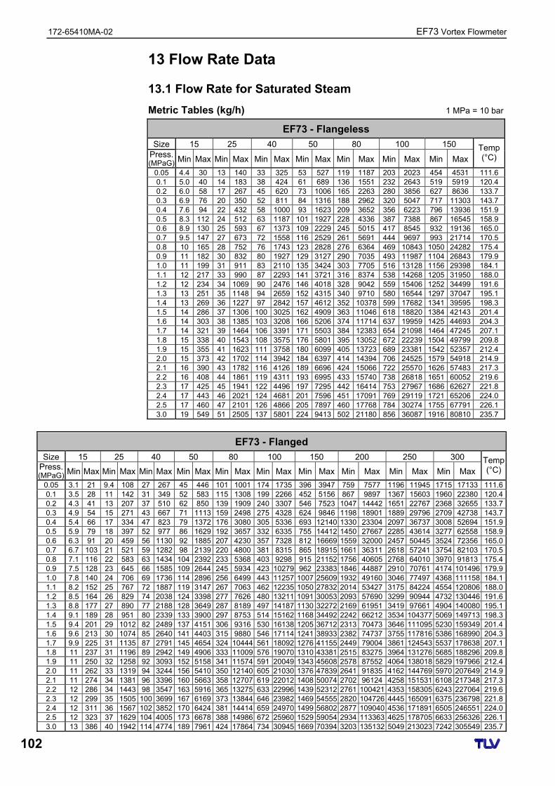
172-65410MA-02 EF73 Vortex Flowmeter
102
13 Flow Rate Data
13.1 Flow Rate for Saturated Steam
Metric Tables (kg/h) 1 MPa = 10 bar
EF73 - Flangeless
Size 15 25 40 50 80 100 150 Press. (MPaG) Min Max Min Max Min Max Min Max Min Max Min Max Min Max
Temp (°C)
0.05 4.4 30 13 140 33 325 53 527 119 1187 203 2023 454 4531 111.6 0.1 5.0 40 14 183 38 424 61 689 136 1551 232 2643 519 5919 120.4 0.2 6.0 58 17 267 45 620 73 1006 165 2263 280 3856 627 8636 133.7 0.3 6.9 76 20 350 52 811 84 1316 188 2962 320 5047 717 11303 143.7 0.4 7.6 94 22 432 58 1000 93 1623 209 3652 356 6223 796 13936 151.9 0.5 8.3 112 24 512 63 1187 101 1927 228 4336 387 7388 867 16545 158.9 0.6 8.9 130 25 593 67 1373 109 2229 245 5015 417 8545 932 19136 165.0 0.7 9.5 147 27 673 72 1558 116 2529 261 5691 444 9697 993 21714 170.5 0.8 10 165 28 752 76 1743 123 2828 276 6364 469 10843 1050 24282 175.4 0.9 11 182 30 832 80 1927 129 3127 290 7035 493 11987 1104 26843 179.9 1.0 11 199 31 911 83 2110 135 3424 303 7705 516 13128 1156 29398 184.1 1.1 12 217 33 990 87 2293 141 3721 316 8374 538 14268 1205 31950 188.0 1.2 12 234 34 1069 90 2476 146 4018 328 9042 559 15406 1252 34499 191.6 1.3 13 251 35 1148 94 2659 152 4315 340 9710 580 16544 1297 37047 195.1 1.4 13 269 36 1227 97 2842 157 4612 352 10378 599 17682 1341 39595 198.3 1.5 14 286 37 1306 100 3025 162 4909 363 11046 618 18820 1384 42143 201.4 1.6 14 303 38 1385 103 3208 166 5206 374 11714 637 19959 1425 44693 204.3 1.7 14 321 39 1464 106 3391 171 5503 384 12383 654 21098 1464 47245 207.1 1.8 15 338 40 1543 108 3575 176 5801 395 13052 672 22239 1504 49799 209.8 1.9 15 355 41 1623 111 3758 180 6099 405 13723 689 23381 1542 52357 212.4 2.0 15 373 42 1702 114 3942 184 6397 414 14394 706 24525 1579 54918 214.9 2.1 16 390 43 1782 116 4126 189 6696 424 15066 722 25570 1626 57483 217.3 2.2 16 408 44 1861 119 4311 193 6995 433 15740 738 26818 1651 60052 219.6 2.3 17 425 45 1941 122 4496 197 7295 442 16414 753 27967 1686 62627 221.8 2.4 17 443 46 2021 124 4681 201 7596 451 17091 769 29119 1721 65206 224.0 2.5 17 460 47 2101 126 4866 205 7897 460 17768 784 30274 1755 67791 226.1 3.0 19 549 51 2505 137 5801 224 9413 502 21180 856 36087 1916 80810 235.7
EF73 - Flanged
Size 15 25 40 50 80 100 150 200 250 300 Press. (MPaG) Min Max Min Max Min Max Min Max Min Max Min Max Min Max Min Max Min Max Min Max
Temp (°C)
0.05 3.1 21 9.4 108 27 267 45 446 101 1001 174 1735 396 3947 759 7577 1196 11945 1715 17133 111.60.1 3.5 28 11 142 31 349 52 583 115 1308 199 2266 452 5156 867 9897 1367 15603 1960 22380 120.40.2 4.3 41 13 207 37 510 62 850 139 1909 240 3307 546 7523 1047 14442 1651 22767 2368 32655 133.70.3 4.9 54 15 271 43 667 71 1113 159 2498 275 4328 624 9846 1198 18901 1889 29796 2709 42738 143.70.4 5.4 66 17 334 47 823 79 1372 176 3080 305 5336 693 12140 1330 23304 2097 36737 3008 52694 151.90.5 5.9 79 18 397 52 977 86 1629 192 3657 332 6335 755 14412 1450 27667 2285 43614 3277 62558 158.90.6 6.3 91 20 459 56 1130 92 1885 207 4230 357 7328 812 16669 1559 32000 2457 50445 3524 72356 165.00.7 6.7 103 21 521 59 1282 98 2139 220 4800 381 8315 865 18915 1661 36311 2618 57241 3754 82103 170.50.8 7.1 116 22 583 63 1434 104 2392 233 5368 403 9298 915 21152 1756 40605 2768 64010 3970 91813 175.40.9 7.5 128 23 645 66 1585 109 2644 245 5934 423 10279 962 23383 1846 44887 2910 70761 4174 101496 179.91.0 7.8 140 24 706 69 1736 114 2896 256 6499 443 11257 1007 25609 1932 49160 3046 77497 4368 111158 184.11.1 8.2 152 25 767 72 1887 119 3147 267 7063 462 12235 1050 27832 2014 53427 3175 84224 4554 120806 188.01.2 8.5 164 26 829 74 2038 124 3398 277 7626 480 13211 1091 30053 2093 57690 3299 90944 4732 130446 191.61.3 8.8 177 27 890 77 2188 128 3649 287 8189 497 14187 1130 32272 2169 61951 3419 97661 4904 140080 195.11.4 9.1 189 28 951 80 2339 133 3900 297 8753 514 15162 1168 34492 2242 66212 3534 104377 5069 149713 198.31.5 9.4 201 29 1012 82 2489 137 4151 306 9316 530 16138 1205 36712 2313 70473 3646 111095 5230 159349 201.41.6 9.6 213 30 1074 85 2640 141 4403 315 9880 546 17114 1241 38933 2382 74737 3755 117816 5386 168990 204.31.7 9.9 225 31 1135 87 2791 145 4654 324 10444 561 18092 1276 41155 2449 79004 3861 124543 5537 178638 207.11.8 11 237 31 1196 89 2942 149 4906 333 11009 576 19070 1310 43381 2515 83275 3964 131276 5685 188296 209.81.9 11 250 32 1258 92 3093 152 5158 341 11574 591 20049 1343 45608 2578 87552 4064 138018 5829 197966 212.42.0 11 262 33 1319 94 3244 156 5410 350 12140 605 21030 1376 47839 2641 91835 4162 144769 5970 207649 214.92.1 11 274 34 1381 96 3396 160 5663 358 12707 619 22012 1408 50074 2702 96124 4258 151531 6108 217348 217.32.2 12 286 34 1443 98 3547 163 5916 365 13275 633 22996 1439 52312 2761 100421 4353 158305 6243 227064 219.62.3 12 299 35 1505 100 3699 167 6169 373 13844 646 23982 1469 54555 2820 104726 4445 165091 6375 236798 221.82.4 12 311 36 1567 102 3852 170 6424 381 14414 659 24970 1499 56802 2877 109040 4536 171891 6505 246551 224.02.5 12 323 37 1629 104 4005 173 6678 388 14986 672 25960 1529 59054 2934 113363 4625 178705 6633 256326 226.13.0 13 386 40 1942 114 4774 189 7961 424 17864 734 30945 1669 70394 3203 135132 5049 213023 7242 305549 235.7
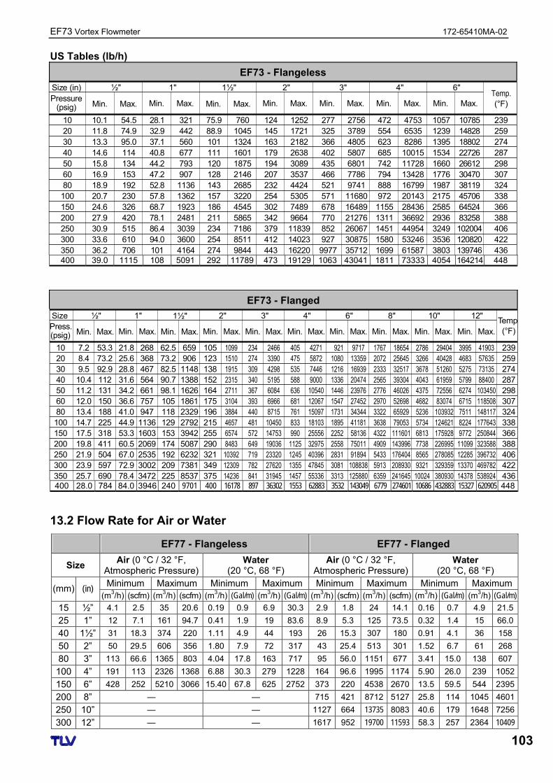
EF73 Vortex Flowmeter 172-65410MA-02
103
US Tables (lb/h)
EF73 - Flangeless
Size (in)
Min. Max.
1"
Min. Max.
1½"
Min. Max.
2"
Min. Max.
3"
Min. Max.
4"
Min. Max.
6"
Min. Max.Temp.(°F)
Pressure(psig)
10 10.1 54.5 28.1 321 75.9 760 124 1252 277 2756 472 4753 1057 10785 23920 11.8 74.9 32.9 442 88.9 1045 145 1721 325 3789 554 6535 1239 14828 25930 13.3 95.0 37.1 560 101 1324 163 2182 366 4805 623 8286 1395 18802 27440 14.6 114 40.8 677 111 1601 179 2638 402 5807 685 10015 1534 22726 28750 15.8 134 44.2 793 120 1875 194 3089 435 6801 742 11728 1660 26612 29860 16.9 153 47.2 907 128 2146 207 3537 466 7786 794 13428 1776 30470 30780 18.9 192 52.8 1136 143 2685 232 4424 521 9741 888 16799 1987 38119 324100 20.7 230 57.8 1362 157 3220 254 5305 571 11680 972 20143 2175 45706 338150 24.6 326 68.7 1923 186 4545 302 7489 678 16489 1155 28436 2585 64524 366200 27.9 420 78.1 2481 211 5865 342 9664 770 21276 1311 36692 2936 83258 388250 30.9 515 86.4 3039 234 7186 379 11839 852 26067 1451 44954 3249 102004 406300 33.6 610 94.0 3600 254 8511 412 14023 927 30875 1580 53246 3536 120820 422350 36.2 706 101 4164 274 9844 443 16220 9977 35712 1699 61587 3803 139746 436
½"
400 39.0 1115 108 5091 292 11789 473 19129 1063 43041 1811 73333 4054 164214 448
EF73 - Flanged
10 7.2 53.3 21.8 268 62.5 659 105 1099 234 2466 405 4271 0921 9717 1767 18654 2786 29404 3995 41903 23920 8.4 73.2 25.6 368 73.2 906 123 1510 274 3390 475 5872 1080 13359 2072 25645 3266 40428 4683 57635 25930 9.5 92.9 28.8 467 82.5 1148 138 1915 309 4298 535 7446 1216 16939 2333 32517 3678 51260 5275 73135 27440 10.4 112 31.6 564 90.7 1388 152 2315 340 5195 588 9000 1336 20474 2565 39304 4043 61959 5799 88400 28750 11.2 131 34.2 661 98.1 1626 164 2711 367 6084 636 10540 1446 23976 2776 46026 4375 72556 6274 103450 29860 12.0 150 36.6 757 105 1861 175 3104 393 6966 681 12067 1547 27452 2970 52698 4682 83074 6715 118508 30780 13.4 188 41.0 947 118 2329 196 3884 440 8715 761 15097 1731 34344 3322 65929 5236 103932 7511 148117 324100 14.7 225 44.9 1136 129 2792 215 4657 481 10450 833 18103 1895 41181 3638 79053 5734 124621 8224 177643 338150 17.5 318 53.3 1603 153 3942 255 6574 572 14753 990 25556 2252 58136 4322 111601 6813 175928 9772 250844 366200 19.8 411 60.5 2069 174 5087 290 8483 649 19036 1125 32975 2558 75011 4909 143996 7738 226995 11099 323588 388250 21.9 504 67.0 2535 192 6232 321 10392 719 23320 1245 40396 2831 91894 5433 176404 8565 278085 12285 396732 406300 23.9 597 72.9 3002 209 7381 349 12309 782 27620 1355 47845 3081 108838 5913 208930 9321 329359 13370 469782 422350 25.7 690 78.4 3472 225 8537 375 14236 841 31945 1457 55336 3313 125880 6359 241645 10024 380930 14378 538924 436
Size
Min. Max.
1"
Min. Max.
1½"
Min. Max.
2"
Min. Max.
3"
Min. Max.
4"
Min. Max.
6"
Min. Max.
8"
Min. Max.
10"
Min. Max.
12"
Min. Max.Temp(°F)Press.
(psig)
½"
400 28.0 784 84.0 3946 240 9701 400 16178 897 36302 1553 62883 3532 143049 6779 274601 10686 432883 15327 620905 448
13.2 Flow Rate for Air or Water
EF77 - Flangeless EF77 - Flanged
Size Air (0 °C / 32 °F,
Atmospheric Pressure) Water
(20 °C, 68 °F) Air (0 °C / 32 °F,
Atmospheric Pressure) Water
(20 °C, 68 °F) Minimum Maximum Minimum Maximum Minimum Maximum Minimum Maximum (mm) (in)
(m3/h) (scfm) (m3/h) (scfm) (m3/h) (Gal/m) (m3/h) (Gal/m) (m3/h) (scfm) (m3/h) (scfm) (m3/h) (Gal/m) (m3/h) (Gal/m)
15 ½” 4.1 2.5 35 20.6 0.19 0.9 6.9 30.3 2.9 1.8 24 14.1 0.16 0.7 4.9 21.5
25 1” 12 7.1 161 94.7 0.41 1.9 19 83.6 8.9 5.3 125 73.5 0.32 1.4 15 66.0
40 1½” 31 18.3 374 220 1.11 4.9 44 193 26 15.3 307 180 0.91 4.1 36 158
50 2” 50 29.5 606 356 1.80 7.9 72 317 43 25.4 513 301 1.52 6.7 61 268
80 3” 113 66.6 1365 803 4.04 17.8 163 717 95 56.0 1151 677 3.41 15.0 138 607
100 4” 191 113 2326 1368 6.88 30.3 279 1228 164 96.6 1995 1174 5.90 26.0 239 1052
150 6” 428 252 5210 3066 15.40 67.8 625 2752 373 220 4538 2670 13.5 59.5 544 2395
200 8” — — 715 421 8712 5127 25.8 114 1045 4601
250 10” — — 1127 664 13735 8083 40.6 179 1648 7256
300 12” — — 1617 952 19700 11593 58.3 257 2364 10409
172-65410MA-02 EF73 Vortex Flowmeter
104
14 Product Warranty
1. Warranty Period One year following product delivery.
2. Warranty Coverage
TLV CO., LTD. warrants this product to the original purchaser to be free from defective materials and workmanship. Under this warranty, the product will be repaired or replaced at our option, without charge for parts or labor.
3. This product warranty will not apply to cosmetic defects, nor to any product
whose exterior has been damaged or defaced; nor does it apply in the following cases:
1) Malfunctions due to improper installation, use, handling, etc., by other than TLV CO., LTD. authorized service representatives.
2) Malfunctions due to dirt, scale, rust, etc.
3) Malfunctions due to improper disassembly and reassembly, or inadequate inspection and maintenance by other than TLV CO., LTD. authorized service representatives.
4) Malfunctions due to disasters or forces of nature.
5) Accidents or malfunctions due to any other cause beyond the control of TLV CO., LTD.
4. Under no circumstances will TLV CO., LTD. be liable for consequential
economic loss damage or consequential damage to property.
EF73 Vortex Flowmeter 172-65410MA-02
105
15 Service
For Service or Technical Assistance:
Contact your representative or your office. In North America:
13901 South Lakes Drive, Charlotte, NC 28273-6790 U.S.A. Tel: [1]-704-597-9070 Fax: [1]-704-583-1610
In Mexico:
San Andrés Atoto No. 12, Col. San Andrés Atoto 53500, Naucalpan, Edo. de México, Mexico Tel: [52]-55-5359-7949 Fax: [52]-55-5359-7585
In Argentina:
Av. Mitre 775, B1603CQH Villa Martelli, Pcia. Buenos Aires, Argentina Tel: [54]-(0)11-4760-8401 Fax: [54]-(0)11-4761-6793
In Europe:
Daimler Benz-Straße 16-18, 74915 Waibstadt, Germany Tel: [49]-(0)7263-9150-0 Fax: [49]-(0)7263-9150-50
Star Lodge, Montpellier Drive, Cheltenham, Gloucestershire GL50 1TY U.K. Tel: [44]-(0)1242-227223 Fax: [44]-(0)1242-223077
Parc d’Ariane 2, bât. C, 290 rue Ferdinand Perrier, 69800 Saint Priest, FRANCE Tel: [33]-(0)4-72482222 Fax: [33]-(0)4-72482220
In Oceania:
Unit 22, 137-145 Rooks Road, Nunawanding, Victoria 3131 Australia Tel: [61]-(0)3-9873 5610 Fax: [61]-(0) 3-9873 5010
In East Asia:
66 Tannery Lane, #03-10B Sindo Building, Singapore 347805 Tel: [65]-6747 4600 Fax: [65]-6742 0345
Room 1306, No. 103 Cao Bao Road, Shanghai, China 200233 Tel: [86]-21-6482-8622 Fax: [86]-21-6482-8623
8 & 8A, Jalan BP 6/6, Bandar Bukit Puchong, 47120 Puchong, Selangor, Malaysia Tel: [60]-3-8065-2928 Fax: [60]-3-8065-2923
#302-1 Bundang Technopark B Yatap, Budang, Seongnam, Gyeonggi, 463-760 Korea Tel: [82]-(0)31-726-2105 Fax: [82]-(0)31-726-2195
Or:
. 881 Nagasuna, Noguchi, Kakogawa, Hyogo 675-8511 Japan Tel: [81]-(0)79-427-1818 Fax: [81]-(0)79-425-1167
Head Office:
881 Nagasuna, Noguchi Kakogawa, Hyogo 675-8511 Japan Tel: [81]-(0)79-422-1122 Fax: [81]-(0)79-422-0112
![OVAL VORTEX FLOWMETER / THERMISTOR TYPE VORTEX … · 2019. 1. 10. · 3 OVAL VORTEX FLOWMETER GBD110E-6 FLOW RANGES The OVAL VORTEX FLOWMETER measures actual flow rate (m3/h[actual])](https://img.pdfslide.us/doc/110x75/5fec29af0bfeaf2fc470a314/oval-vortex-flowmeter-thermistor-type-vortex-2019-1-10-3-oval-vortex-flowmeter.jpg)