Embed Size (px)
Citation preview
P R O J E C T M A N U A L
FOR
DRINKING WATER
SYSTEM REPLACEMENT
AT
VOORHEES HIGH SCHOOL
FOR THE
NORTH HUNTERDON-VOORHEES
REGIONAL HIGH SCHOOL DISTRICT
ANNANDALE, NEW JERSEY
USA PROJECT NO: 2015-077
DATED: MAY 5, 2016
BID SET
USA ARCHITECTS, PLANNERS + INTERIOR DESIGNERS, P.A. 20 North Doughty Avenue
Somerville, NJ 08876
Arnaldo Untoria, AIA
Paul R. Swartz, AIA
Armand T. Christopher, Jr. AIA Mark A. Coan, AIA
Peter C. Campisano, AIA
Daniel Fortunato, AIA
Andrew P. Adornato, AIA
Mitch Miller, AIA, FCSI, CCS
Susan M. DeHart, AIA
No. AI1611600
Andrew P. Adornato, AIA, LEED AP, CDT

Drinking Water System Replacement at USA # 2015-077
Voorhees High School
for the NHVRHSD
TABLE OF CONTENTS PAGE 1 OF 3 2015 USA Architects Planners + Interior Designers, PA
TABLE OF CONTENTS NO.OF PAGES
DIVISION 00 – PROCUREMENT AND CONTRACTING REQUIREMENTS
00 11 13 ADVERTISEMENT FOR BIDS 3
00 21 13 INSTRUCTIONS TO BIDDERS 7
00 31 24 ENVIRONMENTAL REPORTS 1 + 7
00 42 00 FORM OF PROPOSAL-OVERALL (SINGLE PRIME) CONTRACT 3
00 43 13 BID BOND (AIA DOCUMENT A310) 1+2
00 45 14 CERTIFICATION OF NO MATERIAL CHANGE
OF CIRCUMSTANCES 1
00 45 15 AFFIDAVIT REGARDING LIST OF DEBARRED,
SUSPENDED, OR DISQUALIFIED BIDDERS 1
00 45 19 NON-COLLUSION AFFIDAVIT 1
00 45 20 AFFIRMATIVE ACTION QUESTIONNAIRE 1
00 45 20.1 INITIAL PROJECT WORKFORCE REPORT (FORM AA-201) 1
00 45 20.2 MONTHLY PROJECT WORKFORCE REPORT (FORM AA-202) 1
00 45 21 STOCKHOLDER OR PARTNERSHIP DISCLOSURE STATEMENT 2
00 45 22 POLITICAL CONTRIBUTION DISCLOSURE 1+4
00 45 26 DISCLOSURE OF INVESTMENT ACTIVITIES IN IRAN 2
00 45 35 EQUIPMENT CERTIFICATION 3
00 52 13 STANDARD FORM OF AGREEMENT BETWEEN OWNER &
CONTRACTOR (AIA DOCUMENT A101-2007) 1+7
00 61 13 PERFORMANCE BOND AND PAYMENT BOND FORMS COVER 1
00 61 13.13 PERFORMANCE BOND (AIA DOCUMENT A312) 4
00 61 13.16 LABOR AND MATERIALS PAYMENT BOND (AIA DOCUMENT A312) 4
00 62 16 BOARD OF EDUCATION CERTIFICATE OF INSURANCE STATEMENT 1
00 72 00 GENERAL CONDITIONS OF THE CONTRACT FOR
CONSTRUCTION (AIA DOCUMENT A201-2007) 1 + 38
00 73 00 SUPPLEMENTARY CONDITIONS OF THE CONTRACT FOR
CONSTRUCTION 34
00 73 36 EQUAL EMPLOYMENT OPPORTUNITY REQUIREMENTS 4
00 73 46 WAGE RATE REQUIREMENTS 1
00 73 73 STATUTORY DECLARATIONS 4
DIVISION 01 – GENERAL REQUIREMENTS
01 11 00 SUMMARY OF WORK (SINGLE PRIME CONTRACT) 3
01 11 05 TIME OF COMPLETION 1
01 21 00 ALLOWANCES 3
01 25 00 PRODUCT SUBSTITUTIONS 5
01 26 00 MODIFICATION PROCEDURES 3
01 29 00 APPLICATIONS FOR PAYMENT 6
01 31 13 PROJECT COORDINATION 5
01 33 00 SUBMITTALS 8
Drinking Water System Replacement at USA # 2015-077
Voorhees High School
for the NHVRHSD
TABLE OF CONTENTS PAGE 2 OF 3 2015 USA Architects Planners + Interior Designers, PA
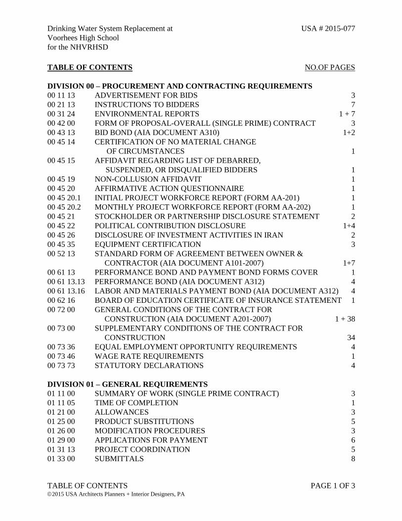
01 40 00 QUALITY CONTROL SERVICES 4
01 42 19 REFERENCE STANDARDS AND DEFINITIONS 3
01 50 00 TEMPORARY CONSTRUCTION FACILITIES AND CONTROLS 6
01 60 00 MATERIALS AND EQUIPMENT 5
01 70 00 PROJECT CLOSEOUT 5
01 71 13 CLEARING SITE AND MOBILIZATION 3
01 73 29 CUTTING AND PATCHING 4
01 74 24 RESTORATION, CLEAN-UP AND DEMOBILIZATION 2
DIVISION 02 – EXISTING CONDITIONS
02 06 31 UTILITY TEST PITS 2
02 41 10 SELECTIVE DEMOLITION 5
DIVISION 03 – CONCRETE
03 11 10 CONCRETE WORK (SITE) 18
03 11 11 CAST-IN-PLACE CONCRETE (TANK BASE SLAB) 8
03 41 36 PRE-CAST POST-TENSION CONCRETE TANKS 25
DIVISION 04 THRU DIVISION 06 – NOT USED
DIVISION 07 – THERMAL AND MOISTURE PROTECTION
07 84 00 FIRE STOPPING 7
07 92 00 JOINT SEALANTS 7
DIVISION 08 THRU DIVISION 25 – NOT USED
DIVISION 26 – ELECTRICAL
26 05 00 COMMON WORK RESULTS FOR ELECTRICAL 6
26 05 19 LOW VOLTAGE ELECTRICAL CONDUCTORS AND CABLES 4
26 05 26 GROUNDING AND BONDING FOR ELECTRICAL SYSTEMS 4
26 05 29 HANGERS AND SUPPORTS FOR ELECTRICAL SYSTEMS 6
26 05 33 RACEWAY AND BOXES FOR ELECTRICAL SYSTEMS 7
26 05 53 IDENTIFICATION FOR ELECTRICAL SYSTEMS 4
26 05 73.17 ARC FLASH HAZARD ANALYSIS/SHORT CIRCUIT/COORDINATION
STUDY 9
26 27 26 WIRING DEVICES 5
26 28 16 ENCLOSED SWITCHES AND CIRCUIT BREAKERS 10
26 28 16.16 ENCLOSED SWITCHES 3
26 32 13 ENGINE-DRIVEN GENERATOR SETS – DIESEL 14
26 36 00 TRANSFER SWITCHES 6
DIVISION 31 – EARTHWORK
31 23 24 BORROW EXCAVATION 2
Drinking Water System Replacement at USA # 2015-077
Voorhees High School
for the NHVRHSD
TABLE OF CONTENTS PAGE 3 OF 3 2015 USA Architects Planners + Interior Designers, PA
31 23 33 TRENCHING AND BACKFILLING 10
31 25 00 EROSION AND SEDIMENTATION CONTROLS 3
DIVISION 32 – EXTERIOR IMPROVEMENTS
32 01 10 PERMANENT PAVEMENT REPAIRS 3
32 13 13 BITUMINOUS CONCRETE DRIVES 1
32 91 10 TOPSOILING, FERTILIZING, SEEDING AND MULCHING 3
DIVISION 33 – UTILITIES
33 05 33 POLYETHYLENE PRESSURE PIPE AND TUBING 8
33 11 00 WATER UTILITY DISTRIBUTION PIPING 12
33 11 20 BEDDING 2
33 1443 PACKAGE PUMPING SYSTEMS FOR WATER UTILITY SERVICE 61
END OF TABLE OF CONTENTS

Drinking Water System Replacement at USA # 2015-077
Voorhees High School
for the NHVRHSD
ADVERTISEMENT FOR BIDS 00 11 13 - 1 2015 USA Architects Planners + Interior Designers, PA
SECTION 00 11 13 - ADVERTISEMENT FOR BIDS
1. Notice is hereby given that sealed bids will be received by the North Hunterdon-Voorhees
Regional High School District, Annandale, New Jersey, for Drinking Water System
Replacement at Voorhees High School.
2. Sealed bids will be received for the following contract:
a. Overall Single Prime (all of the work, Lump Sum, All Trades, All Inclusive)
3. Bids for the above Contract will be received by the Owner in the District Offices located
at 1445 State Route 31, Annandale, New Jersey 08801, until 11:00 a.m.; Local Time, on
June 2, 2016, and will be publicly opened and read aloud immediately thereafter. No bids
shall be received after the time designated in this advertisement. Bidding shall be in
conformance with the applicable requirements of the Public School Contracts Law,
N.J.S.A. 18A18A-1 et seq.
Bidding Documents may be examined online by visiting www.usaplanroom.com. A link
will direct you to USA Architect’s contract printer FLM Reprographics’ “PlanWell
System”, where the documents may be viewed. Bid Documents may be purchased or
ordered for pick-up online for the non-refundable fee of $250.00 for each paper set or
$40.00 for each digital set. The Online system will accept payment by major credit cards
(MasterCard, Visa, American Express), or COD for pick-up. Documents may be sent
prepaid through Federal Express or UPS. Bid Documents will be made available after
2:00 P.M. on May 5, 2016.
Documents will also be made available at FLM Reprographics, 741 Alexander Road,
Princeton, New Jersey 08540, 609-987-0666, Contacts: Jeff Zanin, Bob Strom. Bidders
SHOULD call 24 hours in advance to ensure Bid Documents will be available.
4. A Pre-Bid Conference for the purpose of reviewing the project scope and any possible
clarifications on the intent of the contract documents will be held at 11:00 a.m.; local time,
on May 12, 2016 at Voorhees High School, 256 County Road 513, Glen Gardner, New
Jersey. Meet at Main Entrance of High School. Following the conference, the Architect
will send a written memorandum to all Bidders indicating any addenda and/or clarification
items, if required.
5. Bids must be submitted on the proposal forms in the manner designated, enclosed in a
sealed envelope bearing the name and address of Bidder and proposal identification on the
outside, and must be delivered to the Business Administrator at the above place, by the
hour named. The Board and the Board's Architect or Engineer assume no responsibility
for bids mismailed or misdirected.
Drinking Water System Replacement at USA # 2015-077
Voorhees High School
for the NHVRHSD
ADVERTISEMENT FOR BIDS 00 11 13 - 2 2015 USA Architects Planners + Interior Designers, PA
6. Bids must be accompanied by certified check, cashier's check or Bid Bond drawn to the
Order of the "North Hunterdon-Voorhees Regional High School District" for not less
than ten percent (10%) of the amount of the bid, but in no case in excess of twenty
thousand dollars ($20,000).
7. Each bidder shall submit with its bid, a Certificate of Consent of Surety as per N.J.S.A.
18A:18A-25 from a Surety company stating that it will provide the bidder and all
subcontractors, if successful, with a performance/payment bond in the full amount of the
contract.
8. No bidder may withdraw his bid within 90 days after the actual date of the opening
thereof, N.J.S.A 18A:18A-36a. The Owner reserves the right to extend this date as
negotiated with the potential low bidder.
9. The Owner reserves the right to reject any or all bids or to waive informality in the bidding
if it is in the best interest of the Owner to do so and to award contracts only to those whose
proposal is deemed by the Owner to be most advantageous to the interest of the public.
10. Attention of Bidders is particularly called to the requirements of employment to be
observed and minimum wage rates to be paid under the Contract pursuant to N.J.S.A.
34:11-56.25 et seq.
11. Bidders are required to comply with the requirements of N.J.S.A. 10:5-31 et. seq. and
N.J.A.C. 17:27. In accordance with the provisions of N.J.S.A. 10:5-33, all Bidders are
placed on notice that they are required to comply with the requirements of P.L. 1975,
Chapter 127. (NJAC 17:27.).
12. If the bid exceeds $20,000.00, all bidders shall pre-qualify as required by the State of New
Jersey, Department of the Treasury, Division of Property Management and Construction,
and each bid shall be accompanied by a valid Notice of Classification, a certified
Statement of Uncompleted Contracts and an Affidavit of No Material Adverse Change
pursuant to N.J.S.A. 18A:18A-27 through 18A:18A-33. Bidders shall be prequalified in
Category C008 or C009.
13. Pursuant to the “Public Works Contractor Registration Act” (P.L. 1999, c238), bidders
and their subcontractors are required to be registered with the New Jersey Department of
Labor and to possess a current certificate by said Department indicating compliance with
the Act. Bidders are notified of this requirement of their compliance. If, at the time of the
contract, the certificate from the department has not been received by the bidder, proof of
application along with the cancelled check for the application fee shall be provided to the
Board of Education in lieu of such certificate. Once the certificate is received, a copy of
same shall be delivered forthwith to the Board of Education.
14. Bidders will be required to submit with their bids an Ownership Disclosure Statement
listing the names of all owners of 10% or more of their stock or partnership shares, a Non-
Collusion Affidavit, and a Contractor Questionnaire/Certification. The bid package will
Drinking Water System Replacement at USA # 2015-077
Voorhees High School
for the NHVRHSD
ADVERTISEMENT FOR BIDS 00 11 13 - 3 2015 USA Architects Planners + Interior Designers, PA
include other documents that must be completed and returned with the bid. Failure to
comply with the Instructions to Bidders and to complete and submit all required forms
may be cause for disqualification and rejection of the bid.
15. Bidders shall possess a valid Contractor’s Business Registration Certificate at the time the
bid is received.
BY ORDER OF THE NORTH HUNTERDON-VOORHEES REGIONAL HIGH SCHOOL
DISTRICT
Annandale, New Jersey

Drinking Water System Replacement at USA # 2015-077
Voorhees High School
for the NHVRHSD
INSTRUCTIONS TO BIDDERS 00 21 13 - 1 2015 USA Architects Planners + Interior Designers, PA
SECTION 00 21 13 - INSTRUCTIONS TO BIDDERS
PART 1 - INVITATION
A. Bids for Contracts as listed in the Advertisement for Bids and as herein described will be received
for the performance of the work.
B. Sealed proposals will be received by the Owner at the time and location as indicated in the
Advertisement for Bids.
C. The bids will be publicly opened and read aloud at the date, time and location as indicated in the
Advertisement for Bid.
D. In the event that the Owner revises the time, date or location of bid receipt, such revision will be
issued by Addendum.
PART 2 - BIDDING PROCEDURES
A. The bid shall be submitted, one original and two (2) duplicates, in a sealed envelope addressed to the
Owner, as above, showing the name of the Bidder and identified by the words "Bid for Drinking
Water System Replacement at Voorhees High School”.
B. The sealed envelope shall contain the following, each as one original and two (2) duplicates:
1. The Form of Proposal with all blanks appropriately filled in by typewriter or in ink, with the
bid price indicated both in words and figures. In case of discrepancy between the words and
figures of the bid price, the written words shall govern.
2. The bid guarantee in the form of Bid Bond, AIA Document A310, written by a Surety
authorized to do business in the State of New Jersey in a dollar amount not less than 10% of
the bid sum, (not to exceed $20,000.00). The Bid Bond shall bear the same date as the Form
of Proposal. A certified check, cashiers check in the same amount is also acceptable.
3. A Certificate of Surety from the Bidders Surety Company pursuant to N.J.S.A. 40A:11-22
18A:18A-24 and 25.
4. Affidavit Regarding List of Debarred, Suspended or Disqualified Bidders.
5. Certification of No Material Change of Circumstances.
6. Noncollusion Affidavit.
7. Affirmative Action Affidavit.
8. Stockholder or Partnership Disclosure Statement.
9. Political Contributions Disclosure Form.
Drinking Water System Replacement at USA # 2015-077
Voorhees High School
for the NHVRHSD
INSTRUCTIONS TO BIDDERS 00 21 13 - 2 2015 USA Architects Planners + Interior Designers, PA
10. Disclosure of Investment Activities in Iran
11. Certificate of Insurance Statement.
12. Equipment Certification
13. NJ Department of Treasury Notice of Classification. (Also for named subcontractors)
14. NJ Department of Treasury Total Amount of Uncompleted Contracts Certification, Form
DPMC 701. (Also for named subcontractors)
15. NJ Department of Labor Public Works Contractor Certificate of Registration.
16. Business Registration Certificate issued by the Department of the Treasury, Division of
Revenue. (Also for named subcontractors)
17. Certificate of Authority to perform work in New Jersey issued by the Department of the
Treasury, Division of Taxation. (For out of state Bidders only)
18. Certificate of Authority to Collect Taxes in New Jersey issued by Dept. of Treasury, Div. of
Taxation (Also for named subcontractors)
C. If a bid is submitted by mail, the sealed envelope shall be enclosed in another envelope addressed to
the Owner as above, and including the bid identification. Bids submitted by mail not actually
received by Owner in accordance with the date and time set forth herein shall not be considered.
D. An alteration or erasure on any bidding form shall be initialed by the signer of the Form of Proposal.
E. A bidder shall make no additional stipulations in the Form of Proposal nor qualify his Bid in any
manner. Conditional bids will not be accepted. Bids may be withdrawn prior to the advertised time for
the opening of bids or authorized postponement thereof. Bids received after the advertised time will not
be considered. Bidders shall be solely responsible for premature opening or late delivery of bids not
properly marked or addressed.
F. Each copy of the Form of Proposal shall include the legal name of the Bidder and a Statement that
the Bidder is a sole proprietor, a partnership, a corporation, or some other legal entity. Each copy
shall be signed by the person or persons legally authorized to bind the Bidder to a contract. A bid by
a corporation shall give the state of incorporation and have the corporate seal affixed.
G. The Bidder may modify or withdraw their bid by written notice to the Owner prior to the closing
time set for receipt of bids providing such notice is, in fact, received by the Owner prior to that time
and the Owner is satisfied that a written confirmation of the notice, signed by the Bidder, was
delivered prior to that time. The notice of modification shall quote only the amount to be added to or
subtracted from the bid previously submitted, but shall not reveal any bid sum. Bid security shall be
in an amount sufficient for the Bid as modified.
H. The attorney-in-fact who executes the Bid Bond on behalf of the Surety shall affix to the bond a
certified and current copy of his power of attorney.
Drinking Water System Replacement at USA # 2015-077
Voorhees High School
for the NHVRHSD
INSTRUCTIONS TO BIDDERS 00 21 13 - 3 2015 USA Architects Planners + Interior Designers, PA
I. The Owner will retain the bid securities until either 1) the Contract has been executed and bond and
insurance have been furnished, or 2) the specific time has elapsed so that Bids may be withdrawn, or
3) all Bids have been rejected.
PART 3 - INTERPRETATION AND ADDENDA
A. Copies of Addenda may be issued to Prospective Bidders by facsimile, but all addenda will be
issued at least seven days prior to bid, Saturday, Sundays and Holidays excepted.
B. No Bidder, Prospective Bidder or Sub-bidder shall rely upon any interpretation or correction given
by any method other than Addenda, and neither the Owner nor the Architect will be responsible for
any oral instructions claimed to have been issued by him, them or any of their agents, consultants,
representatives or employees, in any form other than Addenda.
C. Each Bidder shall ascertain, prior to submitting his bid, that he has received all Addenda issued, and
he shall acknowledge their receipt in his proposal.
D. All questions shall be presented to the Architect in writing no later than 10 Business Days prior to
Bid.
PART 4 - BID EVALUATION
A. A bid is invalid if it has not been received at the designated location at the time of or prior to, the
time and date set forth and such invalid bid will not be opened.
B. A bid which does not conform with the requirements of Form of Bids or which contains any
addition, condition or other irregularity is subject to the Owner's rights set forth below.
C. Should the bidder refuse to enter into such Contract or, fail to furnish the required bonds and
insurance, the amount of the bid security shall be forfeited to the Owner as liquidated damages, not
as a penalty.
D. The Bidder acknowledges the right of the Owner to reject any and all bids, to waive any irregularity
in a bid or part thereof and to accept such a bid. In addition, the Bidder recognizes the right of the
Owner to reject a bid if the Bidder failed to furnish the required documents as indicated in Paragraph
“2.B.” of this Section, or if the bid is not submitted on the form provided or is in any way altered,
incomplete or irregular.
PART 5 - BIDDER PREQUALIFICATION
A. Bidders and sub-contractors (where applicable) shall be prequalified by the Division of Building and
Construction, Department of Treasury, State of New Jersey, as to character and amount of public
work on which they may submit bids, pursuant to N.J.S.A. 18A:18-27 through 18A:18-33. Each
Bidder shall submit a notarized affidavit with the Form of Proposal, of an approved form, setting
forth the type and amount of work for which he and his sub-bidder (where applicable) have been
prequalified and verifying that, since qualifying, there has been no material adverse change in
his/their qualification(s) except as noted in the affidavit.
Drinking Water System Replacement at USA # 2015-077
Voorhees High School
for the NHVRHSD
INSTRUCTIONS TO BIDDERS 00 21 13 - 4 2015 USA Architects Planners + Interior Designers, PA
1. Bidders shall be prequalified in Category indicated in the Advertisement for Bids.
B. All inquiries concerning prequalifications shall be directed to the Division of Building and
Construction, Taxation Building, 8th Floor, West State and Willow Streets, Trenton, New Jersey
08625, as well as the New Jersey Schools Development Authority, 1 West State Street, P.O. Box
991, Trenton NJ 08625-0991.
C. The Owner may make such additional investigation as he deems necessary to determine the ability of
the Bidder to perform the work. The Bidder shall furnish to the Owner all such information for this
purpose as the Owner may request. The Owner reserves the right to reject any bid if the evidence
submitted by, or investigation of, such Bidder fails to satisfy the obligations of the Contract or to
complete the work contemplated therein.
PART 6 - PUBLIC WORKS CONTRACTOR REGISTRATION ACT
A. Effective April 11, 2000 all contractors and subcontractors bidding on, or engaging in, any contract
for Public Work, as defined in Section 2 of P.L. 1963, c.150(C34:11-56.26) shall be registered with
the New Jersey Department of Labor and shall provide a copy of his certification with his bid.
Registration forms, copies of the Act and other relevant information is available from the Contractor
Registration Unit, New Jersey Department of Labor, Division of Wage and Hour Compliance, P.O.
Box 389, Trenton, New Jersey 08625-0389. Telephone No. (609) 292-9464, Fax: (609) 633-8591.
PART 6A – BUSINESS REGISTRATION CERTIFICATE
A. Bidders must submit a Business Registration Certificate issued by the NJ Department of Treasury,
Division of Revenue. Bidders using subcontractors shall notify subcontractors in writing that before
a contract can be entered into between the bidder and the subcontractor, the subcontractor must
provide the bidder with a copy of its business registration. The bidder if awarded the contract, shall
forward the subcontractor's business registration to the North Hunterdon-Voorhees High School
District.
B. The bidder shall provide written notice to its subcontractors and suppliers of the responsibility to
submit proof of business registration to the bidder. The requirement of proof of business
registration extends down through all levels (tiers) of the project.
C. Before final payment on the contract is made by the contracting agency, the contractor shall submit
an accurate list and the proof of business registration of each subcontractor or supplier used in the
fulfillment of the contract, or shall attest that no subcontractors were used.
D. For the term of the contract, the contractor and each of its affiliates and a subcontractor and each of
its affiliates [N.J.S.A. 52:32-44(g)(3)] shall collect and remit to the Director, New Jersey Division of
Taxation, the use tax due pursuant to the Sales and Use Tax Act on all sales of tangible personal
property delivered into this State, regardless of whether the tangible personal property is intended
for a contract with a contracting agency.
E. A business organization that fails to provide a copy of a business registration as required pursuant to
section 1 of P.L.2001, c.134 (C.52:32-44 et al.) or subsection e. or f. of section 92 of P.L.1977,
c.110 (C.5:12-92), or that provides false business registration information under the requirements of
Drinking Water System Replacement at USA # 2015-077
Voorhees High School
for the NHVRHSD
INSTRUCTIONS TO BIDDERS 00 21 13 - 5 2015 USA Architects Planners + Interior Designers, PA
either of those sections, shall be liable for a penalty of $25 for each day of violation, not to exceed
$50,000 for each business registration copy not properly provided under a contract with a
contracting agency.
PART 7 - BIDDER'S REPRESENTATION
A. The Bidder, by making his bid, represents that he has visited the site, that he has read and
understands the Bidding Documents, that he will conform with the requirements of Summary of
Work section of Division 01, and that he has included in his bid the cost of all items of work which
are expressly or implicitly required to achieve the completion of the work contemplated by the
Contract under the conditions which will prevail.
B. The Bidder, by making his bid, represents that his failure to include therein the work of any
requirement or provision of the Bidding Documents, or the cost thereof, shall in no way relieve him
from any obligation in respect of his bid.
PART 8 - METHOD OF AWARD
A. Subject to the provisions of Bid Evaluation, the Contract will be awarded to the responsive and
responsible Bidder who submitted the lowest bid, within the limit of funds available.
B. When submission of alternate bids and/or unit prices are required in the Form of Proposal, each
alternate bid or unit price will be considered in the evaluation of bids. If, in the opinion of the
Owner, one or more alternate bid or unit price submitted is not reflective of the reasonable value for
the item of work and could result in substantial, adverse impact in the total cost of the project, the
Owner may declare a bid unresponsive and such bid will be subject to the Owner's rights for bid
evaluation.
C. Should the Bidder refuse to enter into such Contract or fail to furnish the required bonds and
insurance, the amount of the bid security shall be forfeited to the Owner as liquidated damages, not
as a penalty. Pursuant to 18A;18A-36b, the contract shall be signed by all parties within the time
limit set forth in the specifications, which shall not exceed 21 days, Sundays and holidays excepted,
after the making of the award; provided, however, that all parties to the contract may agree to extend
the limit set forth in the specifications beyond the 21 day limit required in this subsection.
PART 9 - BIDDING DOCUMENTS
A. Bidding Documents may be procured from FLM Reprographics as described in the Advertisement
for Bids.
B. Prospective Bidders will be furnished one complete set of Bidding Documents for a non-refundable
fee as indicated in the Advertisement for Bids.
C. Bidding Documents will not be issued direct to Sub-bidders or others.
Drinking Water System Replacement at USA # 2015-077
Voorhees High School
for the NHVRHSD
INSTRUCTIONS TO BIDDERS 00 21 13 - 6 2015 USA Architects Planners + Interior Designers, PA
D. Bidders shall use complete sets of Bidding Documents in preparing bids. Neither the Owner nor the
Architect assume any responsibility for errors or misinterpretation resulting from the use of
incomplete sets of Bidding Documents.
E. Should the Drawings, Specifications or schedules disagree in themselves, or with either or both of
the others, the better quality or greater quantity shall be estimated upon, unless otherwise directed by
Addendum.
F. In case a Prospective Bidder finds discrepancies or omissions in or is in doubt as to the meaning of
the Bidding Documents, he shall at once make inquiry of the Architect, who will issue
interpretations and corrections in the form of Addenda to all Bidders.
G. Whenever a material, article or piece of equipment is identified in the Contract Documents by
reference to manufacturer's or vendor's names, trade names, catalog numbers or the like, it is so
identified for the purpose of establishing a standard and shall not be construed as limiting
competition; and any material, article or piece of equipment of other manufacturers or vendors which
will perform adequately the duties imposed by the general design will be considered equally
acceptable, provided the material, article or piece of equipment so proposed is, of equal substance,
appearance and function and provided it is identified in the Bidding Documents.
H. Bids shall be submitted only on the basis of proprietary materials, articles or pieces of equipment,
prequalified manufacturers, vendors, etc., named in the Bidding Documents and as may be named by
Addendum pursuant to requests for approval made by a Bidder on or before the date and time set
forth above for other inquiries. Such requests shall be fully documented and certified including the
name of the prequalified manufacturer, vendor, material or equipment for which it is to be
substituted and a complete description of the proposed substitute including drawing, catalog cuts,
performance and test data and any other information indicated or as necessary for an evaluation. A
statement shall be included setting forth all changes in other materials, equipment or other work that
incorporation of the substitute would require. The burden of proof of the merit of the proposed
substitute is upon the proposer. The Architect's decision regarding a proposed substitution will be
final.
PART 10 - DEFINITIONS
A. All definitions set forth in the General Conditions are applicable to the Bidding Documents.
B. The Bidding Documents include the Advertisement, Instruction to Bidders, Form of Proposal, Bid
Bond, Disclosure Statement, Noncollusion Affidavit, Affirmative Action Affidavit, the Contract
Documents and all Addenda issued prior to submission of bids.
C. An Addendum is written or graphic instrument, issued by the Architect, which modifies or interprets
the Bidding Documents by additions, deletions, clarifications, or corrections and whose plural form
is Addenda.
D. The Bid is the sum stated in the proposal for which the Bidder offers to perform the work described
in the Bidding Documents.
Drinking Water System Replacement at USA # 2015-077
Voorhees High School
for the NHVRHSD
INSTRUCTIONS TO BIDDERS 00 21 13 - 7 2015 USA Architects Planners + Interior Designers, PA
E. A Prospective Bidder is a Contractor who has been furnished a full set of Bidding Documents
pursuant to the terms of Bidding Documents provisions.
F. A Bidder is a Contractor who submits a bona fide bid in accordance with bidding procedures.
G. A Sub-bidder is a person or entity who submits a proposal to a Prospective Bidder for materials or
labor for a portion of the work.
H. Where the word Owner(s) or a pronoun in place of it occurs in the Bidding Documents, it refers to
the North Hunterdon-Voorhees Regional High School District, 1445 State Route 31, Annandale, New Jersey 08801.
I. Where the word Architect(s) or a pronoun in place of it occurs in the Bidding Documents, it refers to
USA Architects, Planners & Interior Designers, P.A., 20 North Doughty Avenue, Somerville, New
Jersey 08876.
END OF SECTION 00 21 13

Drinking Water System Replacement at USA # 2015-077
Voorhees High School
for the NHVRHSD
ENVIRONMENTAL REPORTS 00 31 24 - 1 2016 USA Architects Planners + Interior Designers, PA
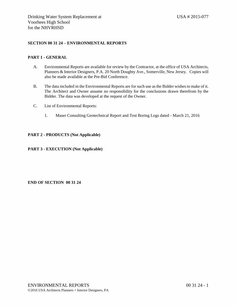
SECTION 00 31 24 – ENVIRONMENTAL REPORTS
PART 1 - GENERAL
A. Environmental Reports are available for review by the Contractor, at the office of USA Architects,
Planners & Interior Designers, P.A. 20 North Doughty Ave., Somerville, New Jersey. Copies will
also be made available at the Pre-Bid Conference.
B. The data included in the Environmental Reports are for such use as the Bidder wishes to make of it.
The Architect and Owner assume no responsibility for the conclusions drawn therefrom by the
Bidder. The data was developed at the request of the Owner.
C. List of Environmental Reports:
1. Maser Consulting Geotechnical Report and Test Boring Logs dated - March 21, 2016
PART 2 - PRODUCTS (Not Applicable)
PART 3 - EXECUTION (Not Applicable)
END OF SECTION 00 31 24

Engineers
Planners
Surveyors
Landscape Architects
Environmental Scientists
Customer Loyalty through Client Satisfaction
941 Marcon Boulevard
Suite 801
Allentown, PA 18109
T: 610.868.4201
F: 610.264.4672
www.maserconsulting.com
March 21, 2016 (Revised)
Ronald Madison, PE
Maser Consulting, PA
941 Marcon Boulevard, Suite 801
Allentown, PA, 18109
Re: Geotechnical Services
North Hunterdon-Voorhees Regional High School District
Voorhees High School Drinking Water System Upgrades
256 County Road 513
Glen Gardner, Hunterdon County, New Jersey
MC Proposal No. 15001563G
Dear Mr. Madison:
In accordance with your request, Maser Consulting P.A. is pleased to present the enclosed test
boring logs and geotechnical related recommendations to assist you in the design and
construction of the proposed drinking water improvements.
Proposed Development
We understand a 20,000 gallon pre-cast water storage tank is currently proposed, occupying a
footprint of approximately 34 feet long by 10 feet wide. The tank pad (or mat) will support the
precast structure and will bear at an approximate depth of 10 feet below grade. A lightly loaded
pump house is also proposed on the tank roof.
Field Evaluation
Subsurface conditions for the proposed underground tank and pump house were explored
through the drilling of two test borings by FMW Drilling of Cinnaminson, NJ, at the locations
indicated on Figure 1. Test borings were performed on December 29, 2015, under the full-time
technical supervision of Maser Consulting. Test borings were logged in accordance with the
Burmister classification system, and are attached to this letter with descriptions of the soil
horizons encountered. The test borings were backfilled with the auger cuttings/excavated
materials to their original ground surface elevations.
Very soft/soft, wet subsurface conditions were encountered in TB-2 from a depths ranging from
about 5 to 11 feet.
Groundwater was not encountered during our field study. However, groundwater levels are
likely to fluctuate based on precipitation events and seasonal influences.
Mr. Ronald Madison, PE MC Project No. 15001563G
March 21, 2016
Page 2 of 4
Conclusions and Recommendations
Tank Support
Depending on the final location of the proposed water tank, some limited stabilization may be
required to support the precast structure at the proposed bearing elevation. If located near TB-2,
some remedial work (i.e. removal and replacement) of the bearing conditions (several feet)
should be anticipated. We do not anticipate these stabilization efforts would be required in the
vicinity of TB-1. Assuming all loose/soft, wet materials are removed and replaced (if
encountered), we recommend the mat be proportioned using a conservative allowable net bearing
capacity of 2,000 psf.
The exposed bearing condition/surface should be evaluated by a qualified Geotechnical Engineer
to determine if the supporting capabilities of the bearing materials are compatible with the design
criteria. All exposed bearing surfaces should be compacted with a roller (as large as practical) in
the static or vibratory modes as directed by the resident Geotechnical Engineer. Loose or
unstable zones detected during foundation construction which cannot be improved in place
should be undercut and replaced with imported dense graded aggregate conforming to NJDOT
901.10.
An aggregate base course of a dense graded aggregate conforming to NJDOT 901.10 is
recommended below the mat/slab to assure uniform support and curing conditions. We
recommend a minimum compacted thickness of 4 inches to achieve this purpose. The dense
graded aggregate base course should be compacted to 95 percent of the maximum dry density, as
determined by the modified Proctor test (ASTM D 1557). We anticipate that, following proper
subgrade preparation (described above), the subgrade soils can achieve a Modulus of Subgrade
Reaction on the order of 150 pounds per cubic inch (pci).
Seismic Site Class
In accordance with the 2009 International Building Code, the proposed improvements may be
designed assuming a Site Class “D”. This classification was determined by utilizing the
Standard Penetration Test (SPT) blow count data through the overburden and blow counts of 100
blows per foot for rock, as permitted by the IBC.
Below-Grade Walls
Below-grade walls should be designed using the soil parameters outlined in Table 1. Note that
these parameters are ultimate values that do not incorporate a factor of safety. Appropriate,
industry-standard factors of safety (typically 1.5 for permanent load cases and 1.3 for transient
load cases), should be applied to the overall design of the wall systems.
Mr. Ronald Madison, PE MC Project No. 15001563G
March 21, 2016
Page 3 of 4
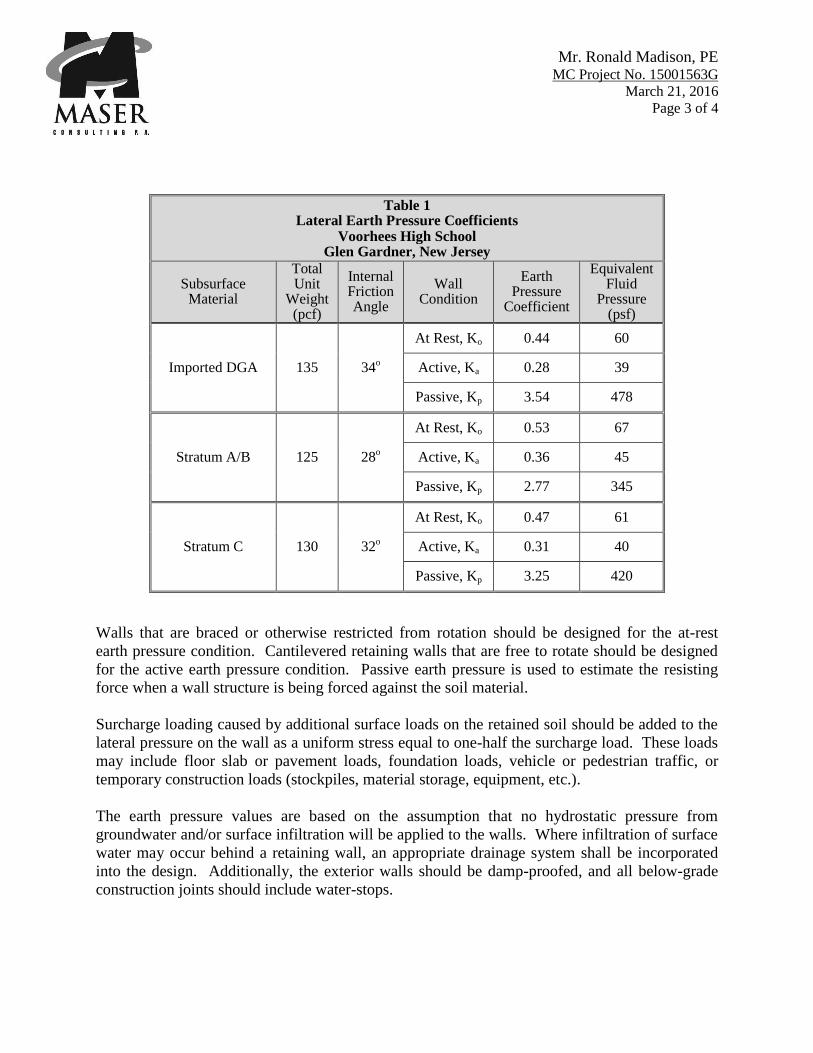
Table 1 Lateral Earth Pressure Coefficients
Voorhees High School Glen Gardner, New Jersey
Subsurface Material
Total Unit
Weight (pcf)
Internal Friction Angle
Wall Condition
Earth Pressure
Coefficient
Equivalent Fluid
Pressure (psf)
Imported DGA 135 34o
At Rest, Ko 0.44 60
Active, Ka 0.28 39
Passive, Kp 3.54 478
Stratum A/B 125 28o
At Rest, Ko 0.53 67
Active, Ka 0.36 45
Passive, Kp 2.77 345
Stratum C 130 32o
At Rest, Ko 0.47 61
Active, Ka 0.31 40
Passive, Kp 3.25 420
Walls that are braced or otherwise restricted from rotation should be designed for the at-rest
earth pressure condition. Cantilevered retaining walls that are free to rotate should be designed
for the active earth pressure condition. Passive earth pressure is used to estimate the resisting
force when a wall structure is being forced against the soil material.
Surcharge loading caused by additional surface loads on the retained soil should be added to the
lateral pressure on the wall as a uniform stress equal to one-half the surcharge load. These loads
may include floor slab or pavement loads, foundation loads, vehicle or pedestrian traffic, or
temporary construction loads (stockpiles, material storage, equipment, etc.).
The earth pressure values are based on the assumption that no hydrostatic pressure from
groundwater and/or surface infiltration will be applied to the walls. Where infiltration of surface
water may occur behind a retaining wall, an appropriate drainage system shall be incorporated
into the design. Additionally, the exterior walls should be damp-proofed, and all below-grade
construction joints should include water-stops.
Mr. Ronald Madison, PE MC Project No. 15001563G
March 21, 2016
Page 4 of 4
We appreciate this opportunity to be of service on this project. Please contact me at (610) 868-
4201 if you have any questions or require any more information.
Very truly yours,
MASER CONSULTING P.A.
Ryan T. Walters, PE
Project Engineer
RTW/djl
cc: P. Gauffreau – Maser Consulting
Attachments (Exploration Location Plan, Test Boring Logs)
\\becad\projects\2015\15001563g\reports\geotechnical\160318_rtw_rbm.docx
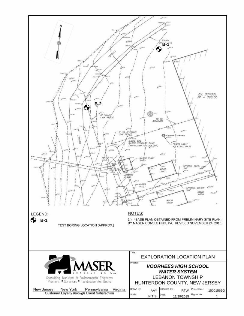
VOORHEES HIGH SCHOOL WATER SYSTEM
LEBANON TOWNSHIP HUNTERDON COUNTY, NEW JERSEY
AAY Drawn By: RTW Checked By: Project No.: 15001563G Scale: N.T.S. Date: 12/29/2015
EXPLORATION LOCATION PLAN Title:
Project:
Figure No.: 1
LEGEND: TEST BORING LOCATION (APPROX.)
1.) *BASE PLAN OBTAINED FROM PRELIMINARY SITE PLAN, BY MASER CONSULTING, PA, REVISED NOVEMBER 24, 2015.
NOTES:
B-1
B-1
B-2

Project Name:Project Location:Project Number:
S - 1 2 3 3 3 60' - 2' 15S - 2 2 3 8 12 112' - 4' 12S - 3 9 10 10 9 204' - 6' 12S - 4 6 7 7 9 146' - 8' 3S - 5 6 7 7 8 14
8' - 10' 10S - 6 6 8 12 31 20
10' - 12' 8
S - 7 24 15 24 15 3913' - 15' 4
S - 8 19 21 50/3 71/918' - 19.2' 6
Maser Representative:Project Manager:Contractor:Driller:Drilling Equipment:Drilling Method:Sampling Method:Date Started:Date Completed:
Comments:
December 29, 2015December 29, 2015G
roun
dwat
er
Dat
a (f
t)
Encountered (ft): NE CME 55/Truck Mounted Drill RigElevation (ft): NA Hollow Stem AugerAt Completion (ft): Caved dry at 10 2-inch O.D. Split Spoon
Gen
eral
Info
rmat
ion
A.YoungP. Gauffreau
40 725
FMW Drilling, Inc.Kevin RyanLo
catio
n In
form
atio
n Elevation (ft): 764.5
745
30 735
755
Sample Recovery =
Sample Recovery =
Sample Recovery =
20
765
Depth (ft)
Sample NumberStandard Penetration
Test Results "N" Value (bpf)
Elev. (ft)Depths Below
Surface (ft) 0-6" 6-12" 12-18"
Subsurface Profile
Profile Stratum Visual Description / Comments
Sample Recovery =
Sample Recovery =
10Sample Recovery =
TEST BORING LOG B-1Pr
ojec
t In
form
atio
nVoorhees High SchoolLebanon Township, NJ15001563G
18-24"0
Sample Recovery =
Sample Recovery =
EngineersPlannersSurveyorsLandscape ArchitectsEnvironmental Scientists
941 Marcon Blvd., Suite 801Allentown, PA 18109
T: 610.868.4201F: 610.264.4672
www.maserconsulting.com
Split Spoon Refusal Notes:1). 4 inches of topsoil2). Split Spoon Refusal at 19.2 feet
S‐1: Top 3": Dark Brown m(+)f SAND, little (‐) Silt (Moist)Bottom 12'': Brown Clayey SILT, little mf(+) Gravel, little (‐) cm(+) Sand (Moist)
S‐2: Brown SILT and CLAY, some (‐) mf(+) Gravel, trace (+)cmf Sand (Moist)
S‐3: Brown Clayey Silt, some c(+)mf Sand, little f Gravel(Moist)
S‐4: Brown mf(+) Gravel, some (+) cmf Sand, trace (+)Silt (Moist)
S‐5: Orange Brown Clayey SILT, some (+) cmf(+) Sand(Dry to Moist)
S‐6: Grayish Brown mf SAND, some mf(+) GRAVEL, trace (+) Clayey Silt; occasional Cobbles (Dry to Moist)
S‐7: Gray cmf GRAVEL, some cmf Sand; frequent Cobbles(Dry)
S‐8: Grayish Brown mf SAND and cmf Gravel, trace clayeySilt (Dry to Moist)
S.S.R.
Stratum C
19.2ft
Stratum A
10ft
Project Name:Project Location:Project Number:
S - 1 1 3 7 8 100' - 2' 6S - 2 5 5 7 7 122' - 4' 10S - 3 7 4 4 4 84' - 6' 12S - 4 3 3 2 2 56' - 8' 10S - 5 1 1 1 1 2
8' - 10' 10S - 6 1 3 5 8 8
10' - 12' 12
S - 7 7 10 50/4 60/1013' - 14.3' 6
Maser Representative:Project Manager:Contractor:Driller:Drilling Equipment:Drilling Method:Sampling Method:Date Started:Date Completed:
TEST BORING LOG B-2Pr
ojec
t In
form
atio
nVoorhees High SchoolLebanon Township, NJ15001563G
18-24" Profile Stratum Visual Description / Comments
0 760
Depth (ft)
Sample NumberStandard Penetration
Test Results "N" Value (bpf)
Subsurface Profile Elev. (ft)Depths Below
Surface (ft) 0-6" 6-12" 12-18"
Sample Recovery =
10Sample Recovery =
750
Sample Recovery =
Sample Recovery =
Sample Recovery =
Sample Recovery =
Sample Recovery =
20 740
30 730
P. Gauffreau
December 29, 2015
40 720
Comments:
Hollow Stem AugerAt Completion (ft): Caved dry at 10 2-inch O.D. Split Spoon
December 29, 2015
FMW Drilling, Inc.Kevin Ryan
Gro
undw
ater
D
ata
(ft)
Encountered (ft): NE CME 55/Truck Mounted Drill RigElevation (ft): NA
Loca
tion
Info
rmat
ion Elevation (ft): 760
Gen
eral
Info
rmat
ion
A.Young
EngineersPlannersSurveyorsLandscape ArchitectsEnvironmental Scientists
941 Marcon Blvd., Suite 801Allentown, PA 18109
T: 610.868.4201F: 610.264.4672
www.maserconsulting.com
Auger RefusalNotes:1). 6 inches of topsoil2). Auger Refusal at 15 feet
S‐1: Dark Brown Clayey Silt and mf(+) Sand, little m(+)fGravel (Moist)
S‐2: Orange Brown Clayey SILT, some (+) mf(+) Gravel, little (‐) m(+)f Sand (Moist)
S‐3: Orange Brown SILT and CLAY, some (+) mf(+) Gravel,little (‐) mf(+) Sand (Moist)
S‐4: Same as S‐4 (Moist to Wet)
S‐5: Orange Brown SILT and CLAY, little mf(+) Sand, trace (‐) f Gravel (Moist to Wet)
S‐6: Orange Brown Clayey Silt and mf(+) Sand, trace (‐) fGravel (Moist)
S‐7: Grayish Brown mf GRAVEL, some (‐) cmf Sand, trace (+) Clayey Silt
A.R.
Stratum C15ft
Stratum A
8ft
Stratum B
11ft
Stratum A13ft
Drinking Water System Replacement at USA # 2015-077
Voorhees High School
for the NHVRHSD
FORM OF PROPOSAL - OVERALL (SINGLE PRIME) CONTRACT 00 42 00 - 1 2015 USA Architects Planners + Interior Designers, PA
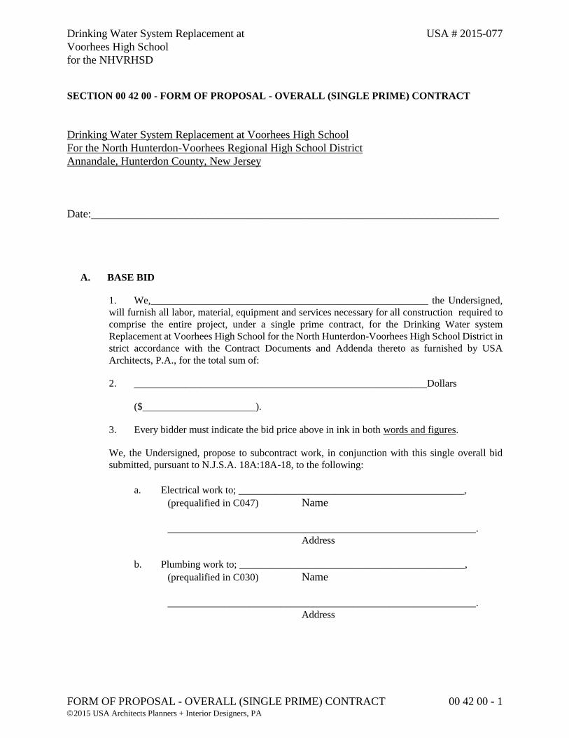
SECTION 00 42 00 - FORM OF PROPOSAL - OVERALL (SINGLE PRIME) CONTRACT
Drinking Water System Replacement at Voorhees High School
For the North Hunterdon-Voorhees Regional High School District
Annandale, Hunterdon County, New Jersey
Date:_________________________________________________________________________
A. BASE BID
1. We,______________________________________________________ the Undersigned,
will furnish all labor, material, equipment and services necessary for all construction required to
comprise the entire project, under a single prime contract, for the Drinking Water system
Replacement at Voorhees High School for the North Hunterdon-Voorhees High School District in
strict accordance with the Contract Documents and Addenda thereto as furnished by USA
Architects, P.A., for the total sum of:
2. _________________________________________________________Dollars
($______________________).
3. Every bidder must indicate the bid price above in ink in both words and figures.
We, the Undersigned, propose to subcontract work, in conjunction with this single overall bid
submitted, pursuant to N.J.S.A. 18A:18A-18, to the following:
a. Electrical work to; ____________________________________________,
(prequalified in C047) Name
____________________________________________________________.
Address
b. Plumbing work to; ____________________________________________,
(prequalified in C030) Name
____________________________________________________________.
Address
Drinking Water System Replacement at USA # 2015-077
Voorhees High School
for the NHVRHSD
FORM OF PROPOSAL - OVERALL (SINGLE PRIME) CONTRACT 00 42 00 - 2 2015 USA Architects Planners + Interior Designers, PA
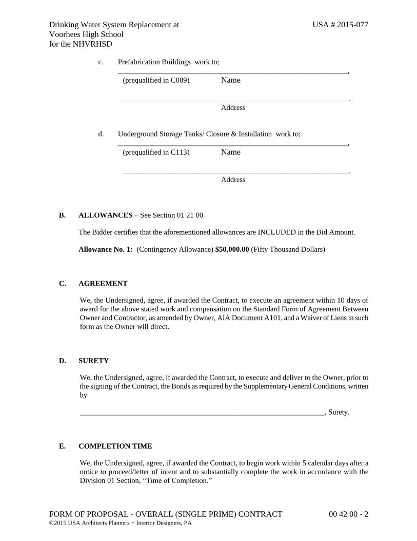
c. Prefabrication Buildings work to;
_____________________________________________________________,
(prequalified in C089) Name
____________________________________________________________.
Address
d. Underground Storage Tanks/ Closure & Installation work to;
_____________________________________________________________,
(prequalified in C113) Name
____________________________________________________________.
Address
B. ALLOWANCES – See Section 01 21 00
The Bidder certifies that the aforementioned allowances are INCLUDED in the Bid Amount.
Allowance No. 1: (Contingency Allowance) $50,000.00 (Fifty Thousand Dollars)
C. AGREEMENT
We, the Undersigned, agree, if awarded the Contract, to execute an agreement within 10 days of
award for the above stated work and compensation on the Standard Form of Agreement Between
Owner and Contractor, as amended by Owner, AIA Document A101, and a Waiver of Liens in such
form as the Owner will direct.
D. SURETY
We, the Undersigned, agree, if awarded the Contract, to execute and deliver to the Owner, prior to
the signing of the Contract, the Bonds as required by the Supplementary General Conditions, written
by
_________________________________________________________________, Surety.
E. COMPLETION TIME
We, the Undersigned, agree, if awarded the Contract, to begin work within 5 calendar days after a
notice to proceed/letter of intent and to substantially complete the work in accordance with the
Division 01 Section, “Time of Completion.”
Drinking Water System Replacement at USA # 2015-077
Voorhees High School
for the NHVRHSD
FORM OF PROPOSAL - OVERALL (SINGLE PRIME) CONTRACT 00 42 00 - 3 2015 USA Architects Planners + Interior Designers, PA
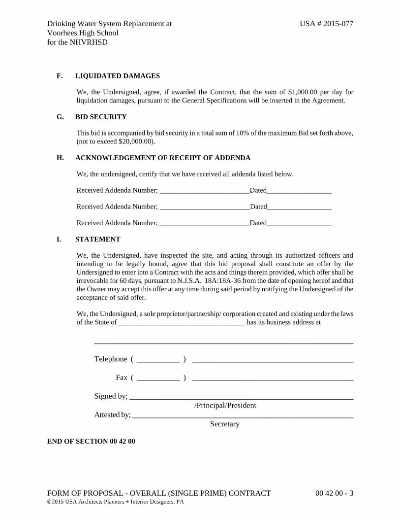
F. LIQUIDATED DAMAGES
We, the Undersigned, agree, if awarded the Contract, that the sum of $1,000.00 per day for
liquidation damages, pursuant to the General Specifications will be inserted in the Agreement.
G. BID SECURITY
This bid is accompanied by bid security in a total sum of 10% of the maximum Bid set forth above,
(not to exceed $20,000.00).
H. ACKNOWLEDGEMENT OF RECEIPT OF ADDENDA
We, the undersigned, certify that we have received all addenda listed below.
Received Addenda Number; _________________________Dated__________________
Received Addenda Number; _________________________Dated__________________
Received Addenda Number; _________________________Dated__________________
I. STATEMENT
We, the Undersigned, have inspected the site, and acting through its authorized officers and
intending to be legally bound, agree that this bid proposal shall constitute an offer by the
Undersigned to enter into a Contract with the acts and things therein provided, which offer shall be
irrevocable for 60 days, pursuant to N.J.S.A. 18A:18A-36 from the date of opening hereof and that
the Owner may accept this offer at any time during said period by notifying the Undersigned of the
acceptance of said offer.
We, the Undersigned, a sole proprietor/partnership/ corporation created and existing under the laws
of the State of ___________________________________ has its business address at
__________________________________________________________________
Telephone ( ___________ ) _________________________________________
Fax ( ___________ ) _________________________________________
Signed by; _________________________________________________________
/Principal/President
Attested by; __________________________________________________________
Secretary
END OF SECTION 00 42 00

Drinking Water System Replacement at USA # 2015-077
Voorhees High School
for the NHVRHSD
BID BOND 00 43 13-1 2015 USA Architects Planners + Interior Designers, PA
SECTION 00 43 13 - BID BOND
The Bid Bond to be executed on behalf of the Owner for Bidding Security is the American Institute of
Architects Document A310 "Bid Bond", 2010 Edition, bound herein, is hereby made part of the Contract
Documents.
Document A310 is enclosed (2 pages) following for the Contractor’s review.
END OF SECTION 00 43 13

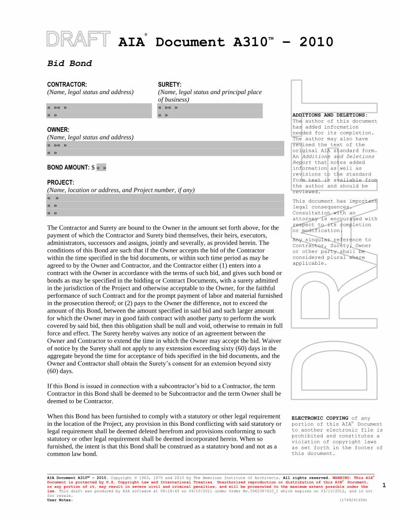
AIA®
Document A310TM
– 2010
Bid Bond
AIA Document A310™ – 2010. Copyright © 1963, 1970 and 2010 by The American Institute of Architects. All rights reserved. WARNING: This AIA®
Document is protected by U.S. Copyright Law and International Treaties. Unauthorized reproduction or distribution of this AIA® Document,
or any portion of it, may result in severe civil and criminal penalties, and will be prosecuted to the maximum extent possible under the
law. This draft was produced by AIA software at 08:18:49 on 09/19/2011 under Order No.5962387410_1 which expires on 03/13/2012, and is not
for resale.
User Notes: (1749241456)
1
ADDITIONS AND DELETIONS:
The author of this document
has added information
needed for its completion.
The author may also have
revised the text of the
original AIA standard form.
An Additions and Deletions
Report that notes added
information as well as
revisions to the standard
form text is available from
the author and should be
reviewed.
This document has important
legal consequences.
Consultation with an
attorney is encouraged with
respect to its completion
or modification.
Any singular reference to
Contractor, Surety, Owner
or other party shall be
considered plural where
applicable.
ELECTRONIC COPYING of any
portion of this AIA® Document
to another electronic file is
prohibited and constitutes a
violation of copyright laws
as set forth in the footer of
this document.
CONTRACTOR: (Name, legal status and address)
SURETY: (Name, legal status and principal place
of business)
« »« »
« »
« »« »
« »
OWNER: (Name, legal status and address)
« »« »
« »
BOND AMOUNT: $ « »
PROJECT: (Name, location or address, and Project number, if any)
« »
« »
« »
The Contractor and Surety are bound to the Owner in the amount set forth above, for the
payment of which the Contractor and Surety bind themselves, their heirs, executors,
administrators, successors and assigns, jointly and severally, as provided herein. The
conditions of this Bond are such that if the Owner accepts the bid of the Contractor
within the time specified in the bid documents, or within such time period as may be
agreed to by the Owner and Contractor, and the Contractor either (1) enters into a
contract with the Owner in accordance with the terms of such bid, and gives such bond or
bonds as may be specified in the bidding or Contract Documents, with a surety admitted
in the jurisdiction of the Project and otherwise acceptable to the Owner, for the faithful
performance of such Contract and for the prompt payment of labor and material furnished
in the prosecution thereof; or (2) pays to the Owner the difference, not to exceed the
amount of this Bond, between the amount specified in said bid and such larger amount
for which the Owner may in good faith contract with another party to perform the work
covered by said bid, then this obligation shall be null and void, otherwise to remain in full
force and effect. The Surety hereby waives any notice of an agreement between the
Owner and Contractor to extend the time in which the Owner may accept the bid. Waiver
of notice by the Surety shall not apply to any extension exceeding sixty (60) days in the
aggregate beyond the time for acceptance of bids specified in the bid documents, and the
Owner and Contractor shall obtain the Surety’s consent for an extension beyond sixty
(60) days.
If this Bond is issued in connection with a subcontractor’s bid to a Contractor, the term
Contractor in this Bond shall be deemed to be Subcontractor and the term Owner shall be
deemed to be Contractor.
When this Bond has been furnished to comply with a statutory or other legal requirement
in the location of the Project, any provision in this Bond conflicting with said statutory or
legal requirement shall be deemed deleted herefrom and provisions conforming to such
statutory or other legal requirement shall be deemed incorporated herein. When so
furnished, the intent is that this Bond shall be construed as a statutory bond and not as a
common law bond.
AIA Document A310™ – 2010. Copyright © 1963, 1970 and 2010 by The American Institute of Architects. All rights reserved. WARNING: This AIA®
Document is protected by U.S. Copyright Law and International Treaties. Unauthorized reproduction or distribution of this AIA® Document,
or any portion of it, may result in severe civil and criminal penalties, and will be prosecuted to the maximum extent possible under the
law. This draft was produced by AIA software at 08:18:49 on 09/19/2011 under Order No.5962387410_1 which expires on 03/13/2012, and is not
for resale.
User Notes: (1749241456)
2
Signed and sealed this « » day of « » , « »
« »
(Contractor as Principal) (Seal)
« »
(Witness) (Title)
« »
(Surety) (Seal)
« »
(Witness) (Title)
Drinking Water System Replacement at USA # 2015-077
Voorhees High School
for the NHVRHSD
CERTIFICATION OF NO MATERIAL CHANGE OF CIRCUMSTANCES 00 45 14- 1 2015 USA Architects Planners + Interior Designers, PA
SECTION 00 45 14 – CERTIFICATION OF NO MATERIAL CHANGE OF CIRCUMSTANCES
Bidder's Name:
Address:
1. A statement as to the financial ability, adequacy of plant equipment, organization and prior
experience of the bidder, as required by N.J.S.A. 18A:18A-28 has been submitted to the
Department of Treasury within the last six (6) months preceding the date of opening of bids
for this contract.
2. I certify, as required by N.J.S.A. 18A: 18A-32 that there has been no material adverse
change in the qualification except:
(Name and Title of Signer - Please print or type)
(Signature) (Date)

Drinking Water System Replacement at USA # 2015-077
Voorhees High School
for the NHVRHSD
AFFIDAVIT REGARDING LIST OF DEBARRED, 00 45 15- 1
SUSPENDED, OR DISQUALIFIED BIDDERS 2015 USA Architects Planners + Interior Designers, PA
SECTION 00 45 15 - AFFIDAVIT REGARDING LIST OF DEBARRED, SUSPENDED OR
DISQUALIFIED BIDDERS
STATE OF NEW JERSEY/______________________________
Specify, of other
COUNTY OF _________________________________________________________________________
I, __________________________________________________________ of the (City, Town, Borough)
of _______________________________________ State of ________________________ of full age,
being duly sworn according to law on my oath depose and say that:
I am _______________________________________________________________________ of the firm
of ________________________________________________________________________ the Bidder
making the Proposal for the above named projects, and that I executed the said Proposal with full
authority to do so; that said Bidder is not at the time of the making this bid included on the New Jersey
State Treasurer's or the Federal Government's List of Debarred, Suspended or Disqualified Bidders as a
result of action taken by any State or Federal Agency.
Name of Contractor; __________________________________
(Company Name)
By; ________________________________________________ (signature of authorized representative)
Subscribed and sworn to before me
this ____ day of _______, 20__.
______________________________
(Seal) Notary Public of New Jersey/
Specify Other State
My Commission expires ______________ 20__

Drinking Water System Replacement at USA # 2015-077
Voorhees High School
for the NHVRHSD
NON-COLLUSION AFFIDAVIT 00 45 19-1 2015 USA Architects Planners + Interior Designers, PA
SECTION 00 45 19 - NONCOLLUSION AFFIDAVIT
I, of the City of , in the County
of , and the State of , of full age, being duly sworn according to law on
my oath depose and say that:
I am of the firm of bidder making
the proposal for the above named Contract, and that I executed the said proposal with full authority
so to do; that said bidder has not, directly or indirectly, entered into any agreement, participated in
any collusion, or otherwise taken any action in restraint of free, competitive bidding in connection
with the above named Contract; and that all statements contained in said proposal and in this
affidavit are true and correct, and made with full knowledge that the Owner relied upon the truth of
the statements contained in said proposal and in the statements contained in this affidavit in
awarding the Contract for the said proposal.
I further warrant that no person or selling agency has been employed or retained to solicit or secure
such Contract upon an agreement or understanding for a commission, percentage, brokerage, or
contingent fee, except bonafide employees or bonafide established commercial or selling agencies
maintained by
.
(Name of Vendor)
Signed:
(also type name of affiant under signature)
Subscribed and sworn to before me
this day of , 20 .
Signature of Notary Public
Notary Public of
My Commission expires , 20 .

Drinking Water System Replacement at USA # 2015-077
Voorhees High School
for the NHVRHSD
AFFIRMATIVE ACTION QUESTIONNAIRE 00 45 20- 1 2015 USA Architects Planners + Interior Designers, PA
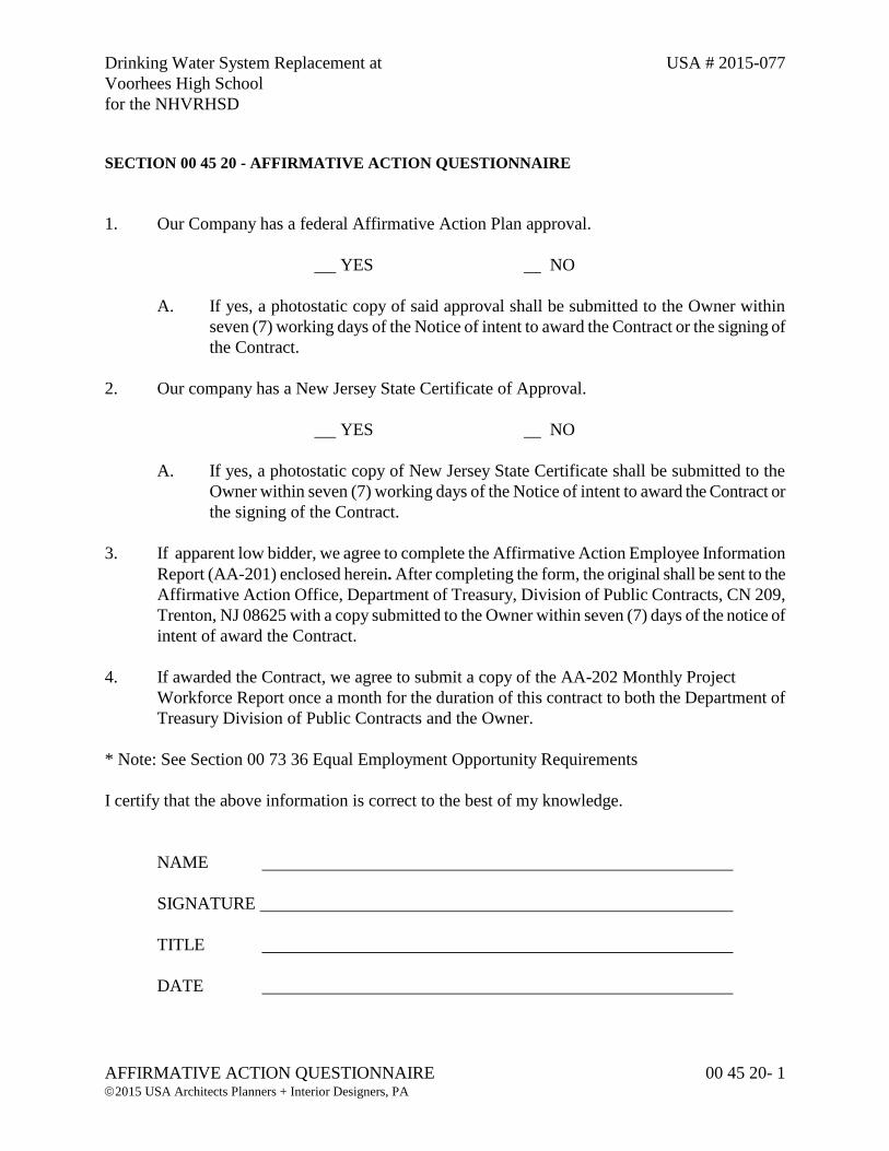
SECTION 00 45 20 - AFFIRMATIVE ACTION QUESTIONNAIRE
1. Our Company has a federal Affirmative Action Plan approval.
YES NO
A. If yes, a photostatic copy of said approval shall be submitted to the Owner within
seven (7) working days of the Notice of intent to award the Contract or the signing of
the Contract.
2. Our company has a New Jersey State Certificate of Approval.
YES NO
A. If yes, a photostatic copy of New Jersey State Certificate shall be submitted to the
Owner within seven (7) working days of the Notice of intent to award the Contract or
the signing of the Contract.
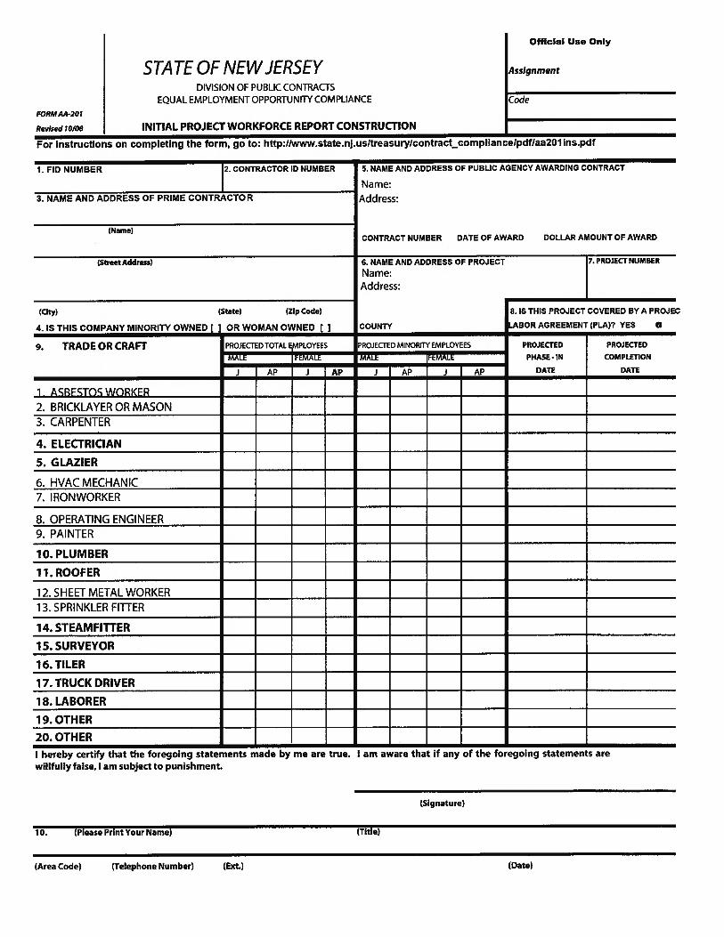
3. If apparent low bidder, we agree to complete the Affirmative Action Employee Information
Report (AA-201) enclosed herein. After completing the form, the original shall be sent to the
Affirmative Action Office, Department of Treasury, Division of Public Contracts, CN 209,
Trenton, NJ 08625 with a copy submitted to the Owner within seven (7) days of the notice of
intent of award the Contract.
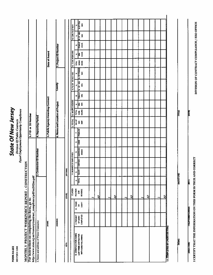
4. If awarded the Contract, we agree to submit a copy of the AA-202 Monthly Project
Workforce Report once a month for the duration of this contract to both the Department of
Treasury Division of Public Contracts and the Owner.
* Note: See Section 00 73 36 Equal Employment Opportunity Requirements
I certify that the above information is correct to the best of my knowledge.
NAME
SIGNATURE
TITLE
DATE

Drinking Water System Replacement at USA # 2015-077
Voorhees High School
for the NHVRHSD
STOCKHOLDER OR PARTNERSHIP DISCLOSURE REQUIREMENT 00 45 21 - 1 2015 USA Architects Planners + Interior Designers, PA
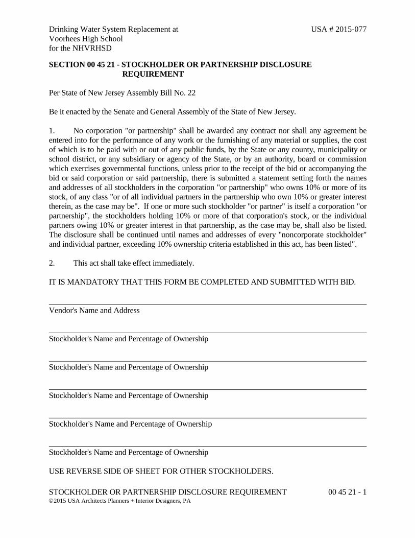
SECTION 00 45 21 - STOCKHOLDER OR PARTNERSHIP DISCLOSURE
REQUIREMENT
Per State of New Jersey Assembly Bill No. 22
Be it enacted by the Senate and General Assembly of the State of New Jersey.
1. No corporation "or partnership" shall be awarded any contract nor shall any agreement be
entered into for the performance of any work or the furnishing of any material or supplies, the cost
of which is to be paid with or out of any public funds, by the State or any county, municipality or
school district, or any subsidiary or agency of the State, or by an authority, board or commission
which exercises governmental functions, unless prior to the receipt of the bid or accompanying the
bid or said corporation or said partnership, there is submitted a statement setting forth the names
and addresses of all stockholders in the corporation "or partnership" who owns 10% or more of its
stock, of any class "or of all individual partners in the partnership who own 10% or greater interest
therein, as the case may be". If one or more such stockholder "or partner" is itself a corporation "or
partnership", the stockholders holding 10% or more of that corporation's stock, or the individual
partners owing 10% or greater interest in that partnership, as the case may be, shall also be listed.
The disclosure shall be continued until names and addresses of every "noncorporate stockholder"
and individual partner, exceeding 10% ownership criteria established in this act, has been listed".
2. This act shall take effect immediately.
IT IS MANDATORY THAT THIS FORM BE COMPLETED AND SUBMITTED WITH BID.
Vendor's Name and Address
Stockholder's Name and Percentage of Ownership
Stockholder's Name and Percentage of Ownership
Stockholder's Name and Percentage of Ownership
Stockholder's Name and Percentage of Ownership
Stockholder's Name and Percentage of Ownership
USE REVERSE SIDE OF SHEET FOR OTHER STOCKHOLDERS.
Drinking Water System Replacement at USA # 2015-077
Voorhees High School
for the NHVRHSD
STOCKHOLDER OR PARTNERSHIP DISCLOSURE REQUIREMENT 00 45 21 - 2 2015 USA Architects Planners + Interior Designers, PA
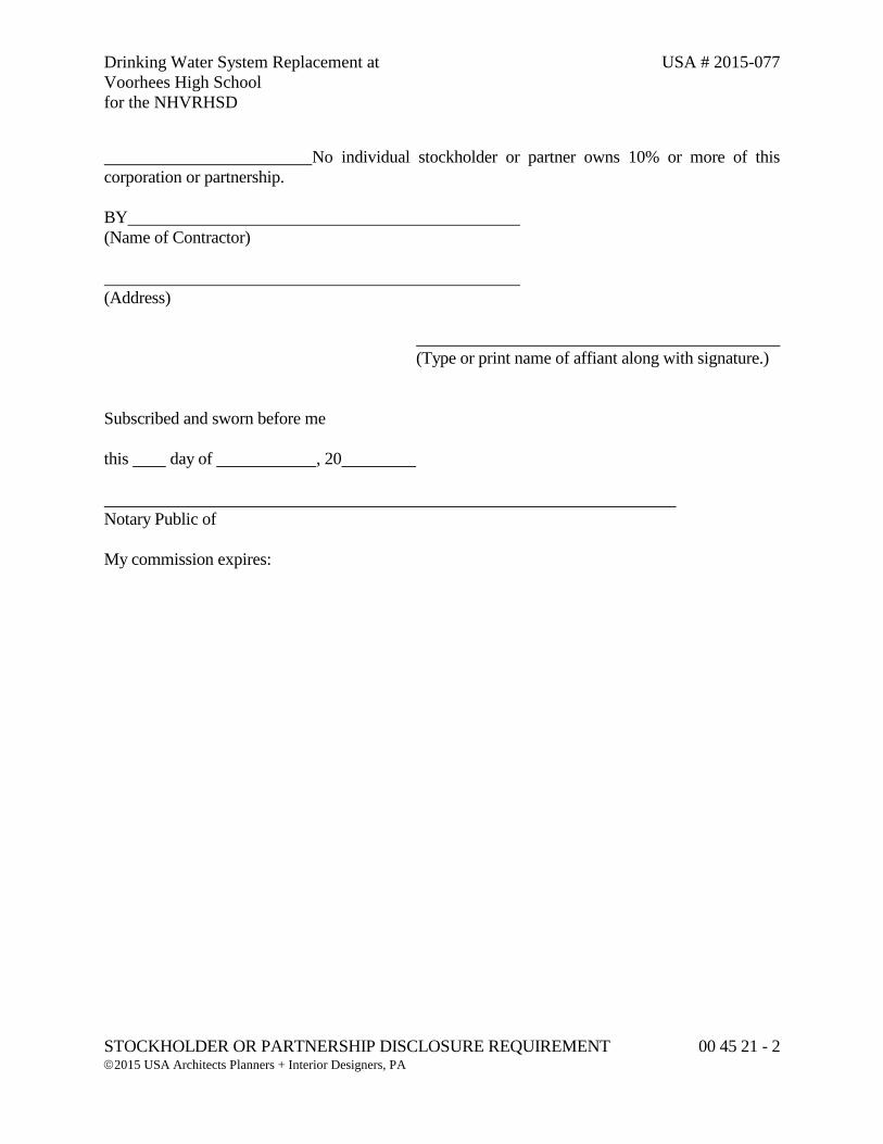
No individual stockholder or partner owns 10% or more of this
corporation or partnership.
BY
(Name of Contractor)
(Address)
(Type or print name of affiant along with signature.)
Subscribed and sworn before me
this day of , 20
Notary Public of
My commission expires:
Drinking Water System Replacement at USA # 2015-077
Voorhees High School
for the NHVRHSD
POLITICAL CONTRIBUTION DISCLOSURE 00 45 22 - 1 2015 USA Architects Planners + Interior Designers, PA
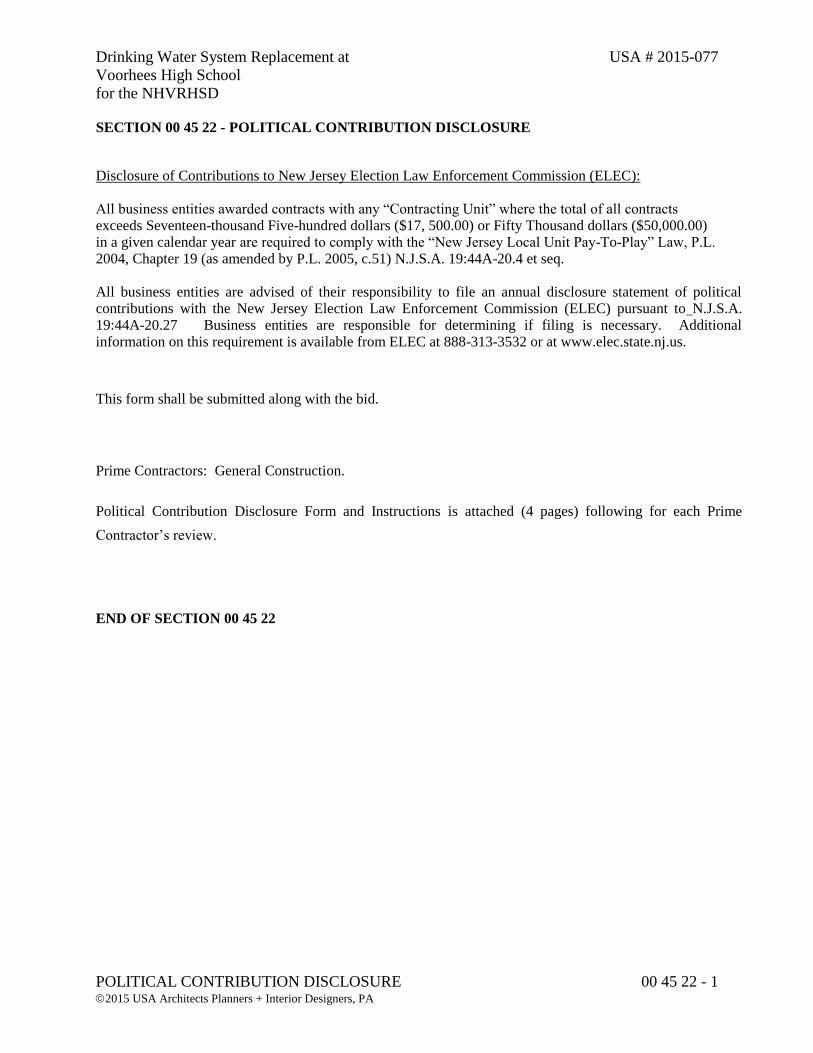
SECTION 00 45 22 - POLITICAL CONTRIBUTION DISCLOSURE
Disclosure of Contributions to New Jersey Election Law Enforcement Commission (ELEC): All business entities awarded contracts with any “Contracting Unit” where the total of all contracts exceeds Seventeen-thousand Five-hundred dollars ($17, 500.00) or Fifty Thousand dollars ($50,000.00) in a given calendar year are required to comply with the “New Jersey Local Unit Pay-To-Play” Law, P.L. 2004, Chapter 19 (as amended by P.L. 2005, c.51) N.J.S.A. 19:44A-20.4 et seq. All business entities are advised of their responsibility to file an annual disclosure statement of political contributions with the New Jersey Election Law Enforcement Commission (ELEC) pursuant to N.J.S.A. 19:44A-20.27 Business entities are responsible for determining if filing is necessary. Additional information on this requirement is available from ELEC at 888-313-3532 or at www.elec.state.nj.us.
This form shall be submitted along with the bid.
Prime Contractors: General Construction.
Political Contribution Disclosure Form and Instructions is attached (4 pages) following for each Prime
Contractor’s review.
END OF SECTION 00 45 22

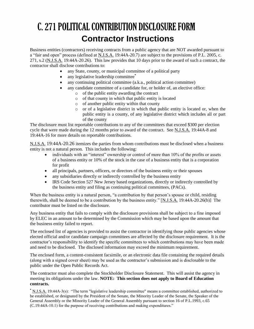
C. 271 POLITICAL CONTRIBUTION DISCLOSURE FORM Contractor Instructions
Business entities (contractors) receiving contracts from a public agency that are NOT awarded pursuant to
a “fair and open” process (defined at N.J.S.A. 19:44A-20.7) are subject to the provisions of P.L. 2005, c.
271, s.2 (N.J.S.A. 19:44A-20.26). This law provides that 10 days prior to the award of such a contract, the
contractor shall disclose contributions to:
any State, county, or municipal committee of a political party
any legislative leadership committee*
any continuing political committee (a.k.a., political action committee)
any candidate committee of a candidate for, or holder of, an elective office:
o of the public entity awarding the contract
o of that county in which that public entity is located
o of another public entity within that county
o or of a legislative district in which that public entity is located or, when the
public entity is a county, of any legislative district which includes all or part
of the county
The disclosure must list reportable contributions to any of the committees that exceed $300 per election
cycle that were made during the 12 months prior to award of the contract. See N.J.S.A. 19:44A-8 and
19:44A-16 for more details on reportable contributions.
N.J.S.A. 19:44A-20.26 itemizes the parties from whom contributions must be disclosed when a business
entity is not a natural person. This includes the following:
individuals with an “interest” ownership or control of more than 10% of the profits or assets
of a business entity or 10% of the stock in the case of a business entity that is a corporation
for profit
all principals, partners, officers, or directors of the business entity or their spouses
any subsidiaries directly or indirectly controlled by the business entity
IRS Code Section 527 New Jersey based organizations, directly or indirectly controlled by
the business entity and filing as continuing political committees, (PACs).
When the business entity is a natural person, “a contribution by that person’s spouse or child, residing
therewith, shall be deemed to be a contribution by the business entity.” [N.J.S.A. 19:44A-20.26(b)] The
contributor must be listed on the disclosure.
Any business entity that fails to comply with the disclosure provisions shall be subject to a fine imposed
by ELEC in an amount to be determined by the Commission which may be based upon the amount that
the business entity failed to report.
The enclosed list of agencies is provided to assist the contractor in identifying those public agencies whose
elected official and/or candidate campaign committees are affected by the disclosure requirement. It is the
contractor’s responsibility to identify the specific committees to which contributions may have been made
and need to be disclosed. The disclosed information may exceed the minimum requirement.
The enclosed form, a content-consistent facsimile, or an electronic data file containing the required details
(along with a signed cover sheet) may be used as the contractor’s submission and is disclosable to the
public under the Open Public Records Act.
The contractor must also complete the Stockholder Disclosure Statement. This will assist the agency in
meeting its obligations under the law. NOTE: This section does not apply to Board of Education
contracts.
* N.J.S.A. 19:44A-3(s): “The term "legislative leadership committee" means a committee established, authorized to
be established, or designated by the President of the Senate, the Minority Leader of the Senate, the Speaker of the
General Assembly or the Minority Leader of the General Assembly pursuant to section 16 of P.L.1993, c.65
(C.19:44A-10.1) for the purpose of receiving contributions and making expenditures.”
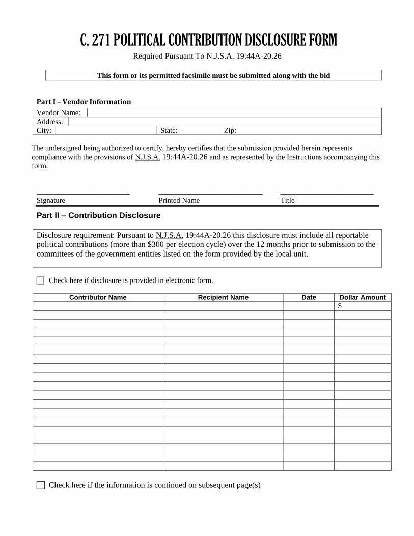
C. 271 POLITICAL CONTRIBUTION DISCLOSURE FORM Required Pursuant To N.J.S.A. 19:44A-20.26
This form or its permitted facsimile must be submitted along with the bid
Part I – Vendor Information
Vendor Name:
Address:
City: State: Zip:
The undersigned being authorized to certify, hereby certifies that the submission provided herein represents
compliance with the provisions of N.J.S.A. 19:44A-20.26 and as represented by the Instructions accompanying this
form.
_________________________ ____________________________ _________________________
Signature Printed Name Title
Part II – Contribution Disclosure
Disclosure requirement: Pursuant to N.J.S.A. 19:44A-20.26 this disclosure must include all reportable
political contributions (more than $300 per election cycle) over the 12 months prior to submission to the
committees of the government entities listed on the form provided by the local unit.
Check here if disclosure is provided in electronic form.
Contributor Name Recipient Name Date Dollar Amount
$
Check here if the information is continued on subsequent page(s)
Continuation Page
C. 271 POLITICAL CONTRIBUTION DISCLOSURE FORM Required Pursuant To N.J.S.A. 19:44A-20.26
Page ___ of ______
Vendor Name:
Contributor Name Recipient Name Date Dollar Amount
$
Check here if the information is continued on subsequent page(s)
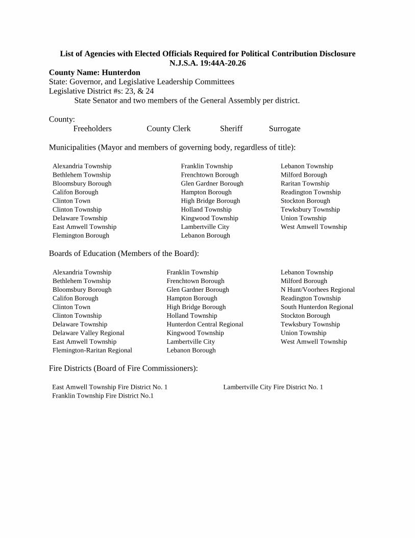
List of Agencies with Elected Officials Required for Political Contribution Disclosure
N.J.S.A. 19:44A-20.26
County Name: Hunterdon
State: Governor, and Legislative Leadership Committees
Legislative District #s: 23, & 24
State Senator and two members of the General Assembly per district.
County:
Freeholders County Clerk Sheriff Surrogate
Municipalities (Mayor and members of governing body, regardless of title):
Alexandria Township
Bethlehem Township
Bloomsbury Borough
Califon Borough
Clinton Town
Clinton Township
Delaware Township
East Amwell Township
Flemington Borough
Franklin Township
Frenchtown Borough
Glen Gardner Borough
Hampton Borough
High Bridge Borough
Holland Township
Kingwood Township
Lambertville City
Lebanon Borough
Lebanon Township
Milford Borough
Raritan Township
Readington Township
Stockton Borough
Tewksbury Township
Union Township
West Amwell Township
Boards of Education (Members of the Board):
Alexandria Township
Bethlehem Township
Bloomsbury Borough
Califon Borough
Clinton Town
Clinton Township
Delaware Township
Delaware Valley Regional
East Amwell Township
Flemington-Raritan Regional
Franklin Township
Frenchtown Borough
Glen Gardner Borough
Hampton Borough
High Bridge Borough
Holland Township
Hunterdon Central Regional
Kingwood Township
Lambertville City
Lebanon Borough
Lebanon Township
Milford Borough
N Hunt/Voorhees Regional
Readington Township
South Hunterdon Regional
Stockton Borough
Tewksbury Township
Union Township
West Amwell Township
Fire Districts (Board of Fire Commissioners):
East Amwell Township Fire District No. 1
Franklin Township Fire District No.1
Lambertville City Fire District No. 1
Drinking Water System Replacement at USA # 2015-077
Voorhees High School
for the NHVRHSD
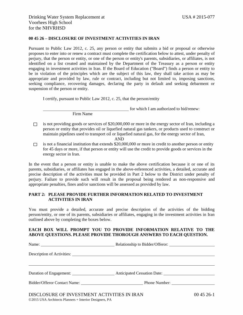
DISCLOSURE OF INVESTMENT ACTIVITIES IN IRAN 00 45 26-1 2015 USA Architects Planners + Interior Designers, PA
00 45 26 – DISCLOSURE OF INVESTMENT ACTIVITIES IN IRAN
Pursuant to Public Law 2012, c. 25, any person or entity that submits a bid or proposal or otherwise
proposes to enter into or renew a contract must complete the certification below to attest, under penalty of
perjury, that the person or entity, or one of the person or entity's parents, subsidiaries, or affiliates, is not
identified on a list created and maintained by the Department of the Treasury as a person or entity
engaging in investment activities in Iran. If the Board of Education ("Board") finds a person or entity to
be in violation of the principles which are the subject of this law, they shall take action as may be
appropriate and provided by law, rule or contract, including but not limited to, imposing sanctions,
seeking compliance, recovering damages, declaring the party in default and seeking debarment or
suspension of the person or entity.
I certify, pursuant to Public Law 2012, c. 25, that the person/entity
for which I am authorized to bid/renew:
Firm Name
is not providing goods or services of $20,000,000 or more in the energy sector of Iran, including a
person or entity that provides oil or liquefied natural gas tankers, or products used to construct or
maintain pipelines used to transport oil or liquefied natural gas, for the energy sector of Iran,
AND
is not a financial institution that extends $20,000,000 or more in credit to another person or entity
for 45 days or more, if that person or entity will use the credit to provide goods or services in the
energy sector in Iran.
In the event that a person or entity is unable to make the above certification because it or one of its
parents, subsidiaries, or affiliates has engaged in the above-referenced activities, a detailed, accurate and
precise description of the activities must be provided in Part 2 below to the District under penalty of
perjury. Failure to provide such will result in the proposal being rendered as non-responsive and
appropriate penalties, fines and/or sanctions will be assessed as provided by law.
PART 2: PLEASE PROVIDE FURTHER INFORMATION RELATED TO INVESTMENT
ACTIVITIES IN IRAN
You must provide a detailed, accurate and precise description of the activities of the bidding
person/entity, or one of its parents, subsidiaries or affiliates, engaging in the investment activities in Iran
outlined above by completing the boxes below.
EACH BOX WILL PROMPT YOU TO PROVIDE INFORMATION RELATIVE TO THE
ABOVE QUESTIONS. PLEASE PROVIDE THOROUGH ANSWERS TO EACH QUESTION.
Name: Relationship to Bidder/Offeror:
Description of Activities:
Duration of Engagement: Anticipated Cessation Date:
Bidder/Offeror Contact Name: Phone Number:
Drinking Water System Replacement at USA # 2015-077
Voorhees High School
for the NHVRHSD
DISCLOSURE OF INVESTMENT ACTIVITIES IN IRAN 00 45 26-2 2015 USA Architects Planners + Interior Designers, PA
Certification I, being duly sworn upon my oath, hereby represent and state that the foregoing
information and any attachments thereto to the best of my knowledge are true and complete. I attest
that I am authorized to execute this certification on behalf of the above-referenced person or entity. I
acknowledge that the Board of Education ("District") is relying on the information contained herein
and thereby acknowledge that I am under a continuing obligation from the date of this certification
through the completion of any contracts with the District to notify the District writing of any changes
to the answers of information contained herein. I acknowledge that I am aware that it is a criminal
offense to make a false statement or misrepresentation in this certification, and if I do so, I recognize
that I am subject to criminal prosecution under the law and that it will also constitute a material
breach of my agreement(s) with the District and that the District at its option may declare any
contract(s) resulting from this certification void and unenforceable.
Full Name: Signature:
Title: Date:
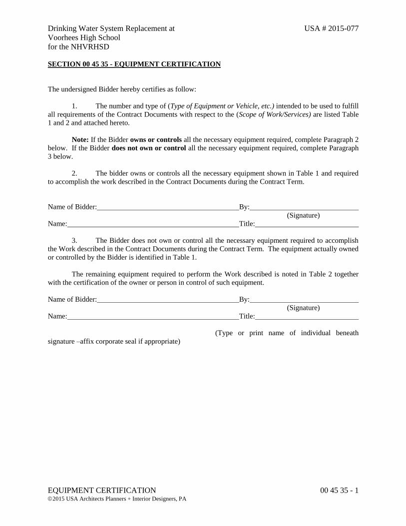
Drinking Water System Replacement at USA # 2015-077
Voorhees High School
for the NHVRHSD
EQUIPMENT CERTIFICATION 00 45 35 - 1 2015 USA Architects Planners + Interior Designers, PA
SECTION 00 45 35 - EQUIPMENT CERTIFICATION
The undersigned Bidder hereby certifies as follow:
1. The number and type of (Type of Equipment or Vehicle, etc.) intended to be used to fulfill
all requirements of the Contract Documents with respect to the (Scope of Work/Services) are listed Table
1 and 2 and attached hereto.
Note: If the Bidder owns or controls all the necessary equipment required, complete Paragraph 2
below. If the Bidder does not own or control all the necessary equipment required, complete Paragraph
3 below.
2. The bidder owns or controls all the necessary equipment shown in Table 1 and required
to accomplish the work described in the Contract Documents during the Contract Term.
Name of Bidder: By:
(Signature)
Name: Title:
3. The Bidder does not own or control all the necessary equipment required to accomplish
the Work described in the Contract Documents during the Contract Term. The equipment actually owned
or controlled by the Bidder is identified in Table 1.
The remaining equipment required to perform the Work described is noted in Table 2 together
with the certification of the owner or person in control of such equipment.
Name of Bidder: By:
(Signature)
Name: Title:
(Type or print name of individual beneath
signature –affix corporate seal if appropriate)
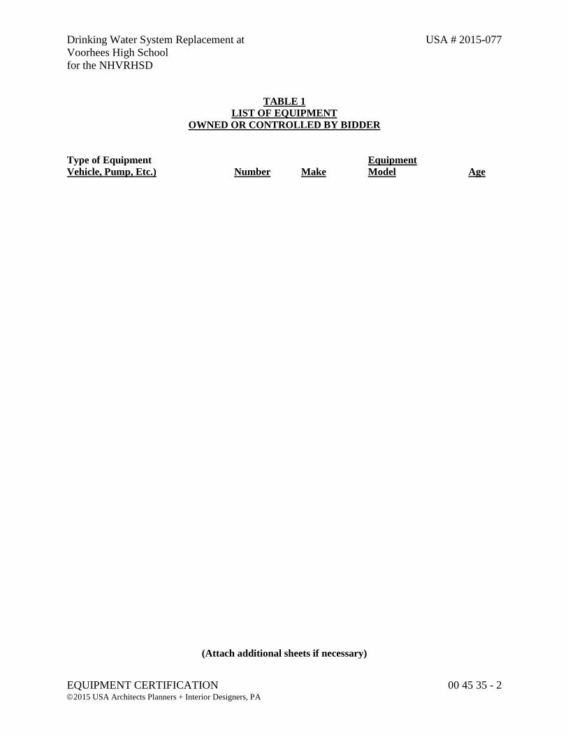
Drinking Water System Replacement at USA # 2015-077
Voorhees High School
for the NHVRHSD
EQUIPMENT CERTIFICATION 00 45 35 - 2 2015 USA Architects Planners + Interior Designers, PA
TABLE 1
LIST OF EQUIPMENT
OWNED OR CONTROLLED BY BIDDER
Type of Equipment Equipment
Vehicle, Pump, Etc.) Number Make Model Age
(Attach additional sheets if necessary)
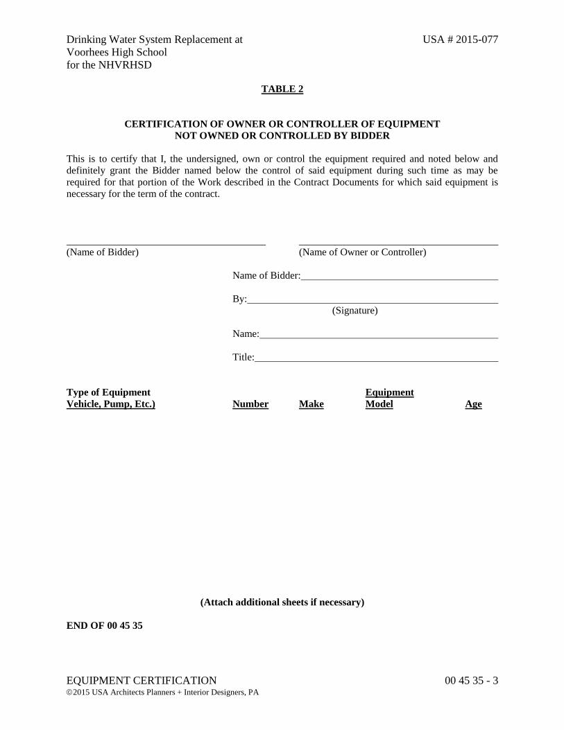
Drinking Water System Replacement at USA # 2015-077
Voorhees High School
for the NHVRHSD
EQUIPMENT CERTIFICATION 00 45 35 - 3 2015 USA Architects Planners + Interior Designers, PA
TABLE 2
CERTIFICATION OF OWNER OR CONTROLLER OF EQUIPMENT
NOT OWNED OR CONTROLLED BY BIDDER
This is to certify that I, the undersigned, own or control the equipment required and noted below and
definitely grant the Bidder named below the control of said equipment during such time as may be
required for that portion of the Work described in the Contract Documents for which said equipment is
necessary for the term of the contract.
(Name of Bidder) (Name of Owner or Controller)
Name of Bidder:
By:
(Signature)
Name:
Title:
Type of Equipment Equipment
Vehicle, Pump, Etc.) Number Make Model Age
(Attach additional sheets if necessary)
END OF 00 45 35

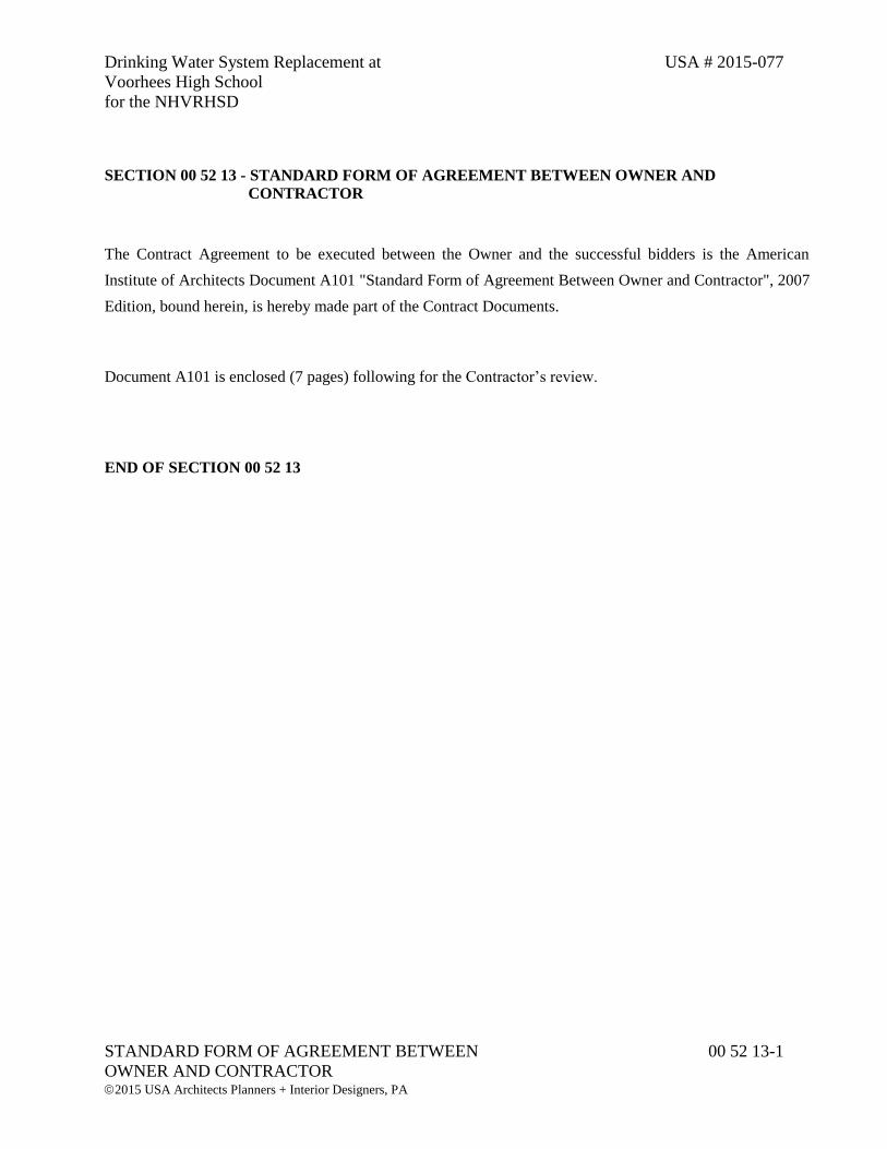
Drinking Water System Replacement at USA # 2015-077
Voorhees High School
for the NHVRHSD
STANDARD FORM OF AGREEMENT BETWEEN 00 52 13-1
OWNER AND CONTRACTOR
2015 USA Architects Planners + Interior Designers, PA
SECTION 00 52 13 - STANDARD FORM OF AGREEMENT BETWEEN OWNER AND
CONTRACTOR
The Contract Agreement to be executed between the Owner and the successful bidders is the American
Institute of Architects Document A101 "Standard Form of Agreement Between Owner and Contractor", 2007
Edition, bound herein, is hereby made part of the Contract Documents.
Document A101 is enclosed (7 pages) following for the Contractor’s review.
END OF SECTION 00 52 13

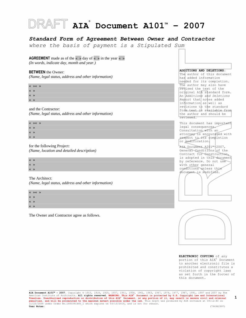
AIA®
Document A101TM
– 2007
Standard Form of Agreement Between Owner and Contractor
where the basis of payment is a Stipulated Sum
AIA Document A101™ – 2007. Copyright © 1915, 1918, 1925, 1937, 1951, 1958, 1961, 1963, 1967, 1974, 1977, 1987, 1991, 1997 and 2007 by The
American Institute of Architects. All rights reserved. WARNING: This AIA® Document is protected by U.S. Copyright Law and International
Treaties. Unauthorized reproduction or distribution of this AIA® Document, or any portion of it, may result in severe civil and criminal
penalties, and will be prosecuted to the maximum extent possible under the law. This draft was produced by AIA software at 09:12:40 on
11/25/2009 under Order No.1000391445_1 which expires on 03/13/2010, and is not for resale.
User Notes: (794982997)
1
ADDITIONS AND DELETIONS:
The author of this document
has added information
needed for its completion.
The author may also have
revised the text of the
original AIA standard form.
An Additions and Deletions
Report that notes added
information as well as
revisions to the standard
form text is available from
the author and should be
reviewed.
This document has important
legal consequences.
Consultation with an
attorney is encouraged with
respect to its completion
or modification.
AIA Document A201™–2007,
General Conditions of the
Contract for Construction,
is adopted in this document
by reference. Do not use
with other general
conditions unless this
document is modified.
ELECTRONIC COPYING of any
portion of this AIA® Document
to another electronic file is
prohibited and constitutes a
violation of copyright laws
as set forth in the footer of
this document.
AGREEMENT made as of the « » day of « » in the year « »
(In words, indicate day, month and year.)
BETWEEN the Owner:
(Name, legal status, address and other information)
« »« »
« »
« »
« »
and the Contractor:
(Name, legal status, address and other information)
« »« »
« »
« »
« »
for the following Project:
(Name, location and detailed description)
« »
« »
« »
The Architect:
(Name, legal status, address and other information)
« »« »
« »
« »
« »
The Owner and Contractor agree as follows.
AIA Document A101™ – 2007. Copyright © 1915, 1918, 1925, 1937, 1951, 1958, 1961, 1963, 1967, 1974, 1977, 1987, 1991, 1997 and 2007 by The
American Institute of Architects. All rights reserved. WARNING: This AIA® Document is protected by U.S. Copyright Law and International
Treaties. Unauthorized reproduction or distribution of this AIA® Document, or any portion of it, may result in severe civil and criminal
penalties, and will be prosecuted to the maximum extent possible under the law. This draft was produced by AIA software at 09:12:40 on
11/25/2009 under Order No.1000391445_1 which expires on 03/13/2010, and is not for resale.
User Notes: (794982997)
2
TABLE OF ARTICLES 1 THE CONTRACT DOCUMENTS 2 THE WORK OF THIS CONTRACT 3 DATE OF COMMENCEMENT AND SUBSTANTIAL COMPLETION 4 CONTRACT SUM 5 PAYMENTS 6 DISPUTE RESOLUTION 7 TERMINATION OR SUSPENSION 8 MISCELLANEOUS PROVISIONS 9 ENUMERATION OF CONTRACT DOCUMENTS 10 INSURANCE AND BONDS
ARTICLE 1 THE CONTRACT DOCUMENTS The Contract Documents consist of this Agreement, Conditions of the Contract (General, Supplementary and other
Conditions), Drawings, Specifications, Addenda issued prior to execution of this Agreement, other documents listed
in this Agreement and Modifications issued after execution of this Agreement, all of which form the Contract, and
are as fully a part of the Contract as if attached to this Agreement or repeated herein. The Contract represents the
entire and integrated agreement between the parties hereto and supersedes prior negotiations, representations or
agreements, either written or oral. An enumeration of the Contract Documents, other than a Modification, appears in
Article 9.
ARTICLE 2 THE WORK OF THIS CONTRACT The Contractor shall fully execute the Work described in the Contract Documents, except as specifically indicated in
the Contract Documents to be the responsibility of others.
ARTICLE 3 DATE OF COMMENCEMENT AND SUBSTANTIAL COMPLETION § 3.1 The date of commencement of the Work shall be the date of this Agreement unless a different date is stated
below or provision is made for the date to be fixed in a notice to proceed issued by the Owner.
(Insert the date of commencement if it differs from the date of this Agreement or, if applicable, state that the date
will be fixed in a notice to proceed.)
« »
If, prior to the commencement of the Work, the Owner requires time to file mortgages and other security interests,
the Owner’s time requirement shall be as follows:
« »
§ 3.2 The Contract Time shall be measured from the date of commencement.
§ 3.3 The Contractor shall achieve Substantial Completion of the entire Work not later than « » ( « » ) days from the
date of commencement, or as follows:
(Insert number of calendar days. Alternatively, a calendar date may be used when coordinated with the date of
commencement. If appropriate, insert requirements for earlier Substantial Completion of certain portions of the
Work.)
« »
AIA Document A101™ – 2007. Copyright © 1915, 1918, 1925, 1937, 1951, 1958, 1961, 1963, 1967, 1974, 1977, 1987, 1991, 1997 and 2007 by The
American Institute of Architects. All rights reserved. WARNING: This AIA® Document is protected by U.S. Copyright Law and International
Treaties. Unauthorized reproduction or distribution of this AIA® Document, or any portion of it, may result in severe civil and criminal
penalties, and will be prosecuted to the maximum extent possible under the law. This draft was produced by AIA software at 09:12:40 on
11/25/2009 under Order No.1000391445_1 which expires on 03/13/2010, and is not for resale.
User Notes: (794982997)
3
Portion of Work Substantial Completion Date
, subject to adjustments of this Contract Time as provided in the Contract Documents.
(Insert provisions, if any, for liquidated damages relating to failure to achieve Substantial Completion on time or for
bonus payments for early completion of the Work.)
« »
ARTICLE 4 CONTRACT SUM § 4.1 The Owner shall pay the Contractor the Contract Sum in current funds for the Contractor’s performance of the
Contract. The Contract Sum shall be « » ($ « » ), subject to additions and deductions as provided in the Contract
Documents.
§ 4.2 The Contract Sum is based upon the following alternates, if any, which are described in the Contract
Documents and are hereby accepted by the Owner:
(State the numbers or other identification of accepted alternates. If the bidding or proposal documents permit the
Owner to accept other alternates subsequent to the execution of this Agreement, attach a schedule of such other
alternates showing the amount for each and the date when that amount expires.)
« »
§ 4.3 Unit prices, if any:
(Identify and state the unit price; state quantity limitations, if any, to which the unit price will be applicable.)
Item Units and Limitations Price Per Unit ($0.00)
§ 4.4 Allowances included in the Contract Sum, if any:
(Identify allowance and state exclusions, if any, from the allowance price.)
Item Price
ARTICLE 5 PAYMENTS § 5.1 PROGRESS PAYMENTS § 5.1.1 Based upon Applications for Payment submitted to the Architect by the Contractor and Certificates for
Payment issued by the Architect, the Owner shall make progress payments on account of the Contract Sum to the
Contractor as provided below and elsewhere in the Contract Documents.
§ 5.1.2 The period covered by each Application for Payment shall be one calendar month ending on the last day of
the month, or as follows:
« »
§ 5.1.3 Provided that an Application for Payment is received by the Architect not later than the « » day of a month,
the Owner shall make payment of the certified amount to the Contractor not later than the « » day of the « » month.
If an Application for Payment is received by the Architect after the application date fixed above, payment shall be
made by the Owner not later than « » ( « » ) days after the Architect receives the Application for Payment.
(Federal, state or local laws may require payment within a certain period of time.)
§ 5.1.4 Each Application for Payment shall be based on the most recent schedule of values submitted by the
Contractor in accordance with the Contract Documents. The schedule of values shall allocate the entire Contract
Sum among the various portions of the Work. The schedule of values shall be prepared in such form and supported
by such data to substantiate its accuracy as the Architect may require. This schedule, unless objected to by the
Architect, shall be used as a basis for reviewing the Contractor’s Applications for Payment.
AIA Document A101™ – 2007. Copyright © 1915, 1918, 1925, 1937, 1951, 1958, 1961, 1963, 1967, 1974, 1977, 1987, 1991, 1997 and 2007 by The
American Institute of Architects. All rights reserved. WARNING: This AIA® Document is protected by U.S. Copyright Law and International
Treaties. Unauthorized reproduction or distribution of this AIA® Document, or any portion of it, may result in severe civil and criminal
penalties, and will be prosecuted to the maximum extent possible under the law. This draft was produced by AIA software at 09:12:40 on
11/25/2009 under Order No.1000391445_1 which expires on 03/13/2010, and is not for resale.
User Notes: (794982997)
4
§ 5.1.5 Applications for Payment shall show the percentage of completion of each portion of the Work as of the end
of the period covered by the Application for Payment.
§ 5.1.6 Subject to other provisions of the Contract Documents, the amount of each progress payment shall be
computed as follows:
.1 Take that portion of the Contract Sum properly allocable to completed Work as determined by
multiplying the percentage completion of each portion of the Work by the share of the Contract Sum
allocated to that portion of the Work in the schedule of values, less retainage of « » percent ( « » %).
Pending final determination of cost to the Owner of changes in the Work, amounts not in dispute
shall be included as provided in Section 7.3.9 of AIA Document A201™–2007, General Conditions
of the Contract for Construction;
.2 Add that portion of the Contract Sum properly allocable to materials and equipment delivered and
suitably stored at the site for subsequent incorporation in the completed construction (or, if approved
in advance by the Owner, suitably stored off the site at a location agreed upon in writing), less
retainage of « » percent ( « » %);
.3 Subtract the aggregate of previous payments made by the Owner; and
.4 Subtract amounts, if any, for which the Architect has withheld or nullified a Certificate for Payment
as provided in Section 9.5 of AIA Document A201–2007.
§ 5.1.7 The progress payment amount determined in accordance with Section 5.1.6 shall be further modified under
the following circumstances:
.1 Add, upon Substantial Completion of the Work, a sum sufficient to increase the total payments to the
full amount of the Contract Sum, less such amounts as the Architect shall determine for incomplete
Work, retainage applicable to such work and unsettled claims; and
(Section 9.8.5 of AIA Document A201–2007 requires release of applicable retainage upon
Substantial Completion of Work with consent of surety, if any.)
.2 Add, if final completion of the Work is thereafter materially delayed through no fault of the
Contractor, any additional amounts payable in accordance with Section 9.10.3 of AIA Document
A201–2007.
§ 5.1.8 Reduction or limitation of retainage, if any, shall be as follows:
(If it is intended, prior to Substantial Completion of the entire Work, to reduce or limit the retainage resulting from
the percentages inserted in Sections 5.1.6.1 and 5.1.6.2 above, and this is not explained elsewhere in the Contract
Documents, insert here provisions for such reduction or limitation.)
« »
§ 5.1.9 Except with the Owner’s prior approval, the Contractor shall not make advance payments to suppliers for
materials or equipment which have not been delivered and stored at the site.
§ 5.2 FINAL PAYMENT § 5.2.1 Final payment, constituting the entire unpaid balance of the Contract Sum, shall be made by the Owner to the
Contractor when
.1 the Contractor has fully performed the Contract except for the Contractor’s responsibility to correct
Work as provided in Section 12.2.2 of AIA Document A201–2007, and to satisfy other requirements,
if any, which extend beyond final payment; and
.2 a final Certificate for Payment has been issued by the Architect.
§ 5.2.2 The Owner’s final payment to the Contractor shall be made no later than 30 days after the issuance of the
Architect’s final Certificate for Payment, or as follows:
« »
ARTICLE 6 DISPUTE RESOLUTION § 6.1 INITIAL DECISION MAKER The Architect will serve as Initial Decision Maker pursuant to Section 15.2 of AIA Document A201–2007, unless
the parties appoint below another individual, not a party to this Agreement, to serve as Initial Decision Maker.
AIA Document A101™ – 2007. Copyright © 1915, 1918, 1925, 1937, 1951, 1958, 1961, 1963, 1967, 1974, 1977, 1987, 1991, 1997 and 2007 by The
American Institute of Architects. All rights reserved. WARNING: This AIA® Document is protected by U.S. Copyright Law and International
Treaties. Unauthorized reproduction or distribution of this AIA® Document, or any portion of it, may result in severe civil and criminal
penalties, and will be prosecuted to the maximum extent possible under the law. This draft was produced by AIA software at 09:12:40 on
11/25/2009 under Order No.1000391445_1 which expires on 03/13/2010, and is not for resale.
User Notes: (794982997)
5
(If the parties mutually agree, insert the name, address and other contact information of the Initial Decision Maker,
if other than the Architect.)
« »
« »
« »
« »
§ 6.2 BINDING DISPUTE RESOLUTION For any Claim subject to, but not resolved by, mediation pursuant to Section 15.3 of AIA Document A201–2007, the
method of binding dispute resolution shall be as follows:
(Check the appropriate box. If the Owner and Contractor do not select a method of binding dispute resolution
below, or do not subsequently agree in writing to a binding dispute resolution method other than litigation, Claims
will be resolved by litigation in a court of competent jurisdiction.)
[ « » ] Arbitration pursuant to Section 15.4 of AIA Document A201–2007
[ « » ] Litigation in a court of competent jurisdiction
[ « » ] Other (Specify)
« »
ARTICLE 7 TERMINATION OR SUSPENSION § 7.1 The Contract may be terminated by the Owner or the Contractor as provided in Article 14 of AIA Document
A201–2007.
§ 7.2 The Work may be suspended by the Owner as provided in Article 14 of AIA Document A201–2007.
ARTICLE 8 MISCELLANEOUS PROVISIONS § 8.1 Where reference is made in this Agreement to a provision of AIA Document A201–2007 or another Contract
Document, the reference refers to that provision as amended or supplemented by other provisions of the Contract
Documents.
§ 8.2 Payments due and unpaid under the Contract shall bear interest from the date payment is due at the rate stated
below, or in the absence thereof, at the legal rate prevailing from time to time at the place where the Project is
located.
(Insert rate of interest agreed upon, if any.)
« » % « »
§ 8.3 The Owner’s representative:
(Name, address and other information)
« »
« »
« »
« »
« »
« »
§ 8.4 The Contractor’s representative:
(Name, address and other information)
« »
« »
« »
« »
AIA Document A101™ – 2007. Copyright © 1915, 1918, 1925, 1937, 1951, 1958, 1961, 1963, 1967, 1974, 1977, 1987, 1991, 1997 and 2007 by The
American Institute of Architects. All rights reserved. WARNING: This AIA® Document is protected by U.S. Copyright Law and International
Treaties. Unauthorized reproduction or distribution of this AIA® Document, or any portion of it, may result in severe civil and criminal
penalties, and will be prosecuted to the maximum extent possible under the law. This draft was produced by AIA software at 09:12:40 on
11/25/2009 under Order No.1000391445_1 which expires on 03/13/2010, and is not for resale.
User Notes: (794982997)
6
« »
« »
§ 8.5 Neither the Owner’s nor the Contractor’s representative shall be changed without ten days written notice to the
other party.
§ 8.6 Other provisions:
« »
ARTICLE 9 ENUMERATION OF CONTRACT DOCUMENTS § 9.1 The Contract Documents, except for Modifications issued after execution of this Agreement, are enumerated in
the sections below.
§ 9.1.1 The Agreement is this executed AIA Document A101–2007, Standard Form of Agreement Between Owner
and Contractor.
§ 9.1.2 The General Conditions are AIA Document A201–2007, General Conditions of the Contract for
Construction.
§ 9.1.3 The Supplementary and other Conditions of the Contract:
Document Title Date Pages
§ 9.1.4 The Specifications:
(Either list the Specifications here or refer to an exhibit attached to this Agreement.)
« »
Section Title Date Pages
§ 9.1.5 The Drawings:
(Either list the Drawings here or refer to an exhibit attached to this Agreement.)
« »
Number Title Date
§ 9.1.6 The Addenda, if any:
Number Date Pages
Portions of Addenda relating to bidding requirements are not part of the Contract Documents unless the bidding
requirements are also enumerated in this Article 9.
§ 9.1.7 Additional documents, if any, forming part of the Contract Documents:
.1 AIA Document E201™–2007, Digital Data Protocol Exhibit, if completed by the parties, or the
following:
« »
.2 Other documents, if any, listed below:
(List here any additional documents that are intended to form part of the Contract Documents. AIA
Document A201–2007 provides that bidding requirements such as advertisement or invitation to bid,
Instructions to Bidders, sample forms and the Contractor’s bid are not part of the Contract
AIA Document A101™ – 2007. Copyright © 1915, 1918, 1925, 1937, 1951, 1958, 1961, 1963, 1967, 1974, 1977, 1987, 1991, 1997 and 2007 by The
American Institute of Architects. All rights reserved. WARNING: This AIA® Document is protected by U.S. Copyright Law and International
Treaties. Unauthorized reproduction or distribution of this AIA® Document, or any portion of it, may result in severe civil and criminal
penalties, and will be prosecuted to the maximum extent possible under the law. This draft was produced by AIA software at 09:12:40 on
11/25/2009 under Order No.1000391445_1 which expires on 03/13/2010, and is not for resale.
User Notes: (794982997)
7
Documents unless enumerated in this Agreement. They should be listed here only if intended to be
part of the Contract Documents.)
« »
ARTICLE 10 INSURANCE AND BONDS The Contractor shall purchase and maintain insurance and provide bonds as set forth in Article 11 of AIA Document
A201–2007.
(State bonding requirements, if any, and limits of liability for insurance required in Article 11 of AIA Document
A201–2007.)
Type of insurance or bond Limit of liability or bond amount ($0.00)
This Agreement entered into as of the day and year first written above.
OWNER (Signature) CONTRACTOR (Signature)
« »« » « »« »
(Printed name and title) (Printed name and title)

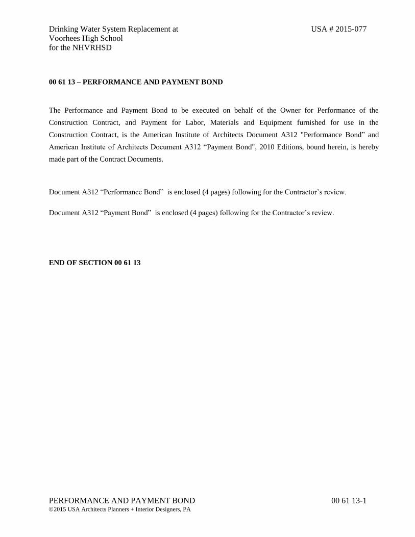
Drinking Water System Replacement at USA # 2015-077
Voorhees High School
for the NHVRHSD
PERFORMANCE AND PAYMENT BOND 00 61 13-1 2015 USA Architects Planners + Interior Designers, PA
00 61 13 – PERFORMANCE AND PAYMENT BOND
The Performance and Payment Bond to be executed on behalf of the Owner for Performance of the
Construction Contract, and Payment for Labor, Materials and Equipment furnished for use in the
Construction Contract, is the American Institute of Architects Document A312 "Performance Bond” and
American Institute of Architects Document A312 “Payment Bond", 2010 Editions, bound herein, is hereby
made part of the Contract Documents.
Document A312 “Performance Bond” is enclosed (4 pages) following for the Contractor’s review.
Document A312 “Payment Bond” is enclosed (4 pages) following for the Contractor’s review.
END OF SECTION 00 61 13

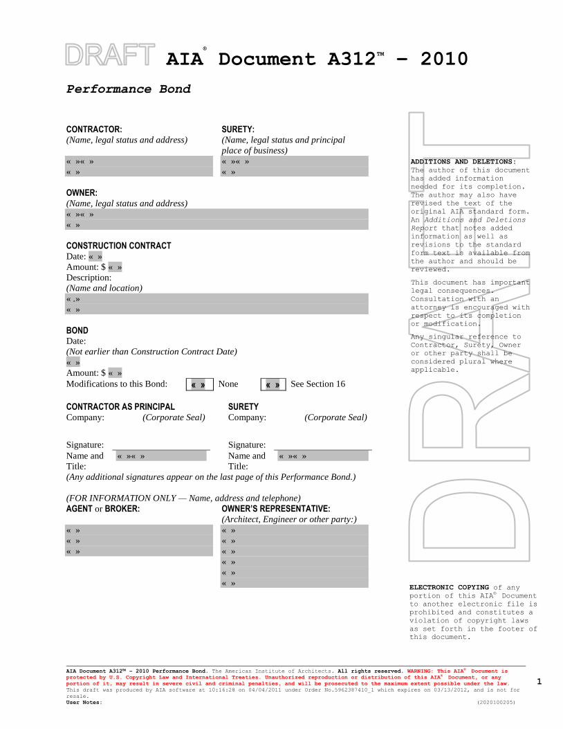
AIA®
Document A312TM
– 2010
Performance Bond
AIA Document A312™ – 2010 Performance Bond. The American Institute of Architects. All rights reserved. WARNING: This AIA® Document is
protected by U.S. Copyright Law and International Treaties. Unauthorized reproduction or distribution of this AIA® Document, or any
portion of it, may result in severe civil and criminal penalties, and will be prosecuted to the maximum extent possible under the law.
This draft was produced by AIA software at 10:16:28 on 04/04/2011 under Order No.5962387410_1 which expires on 03/13/2012, and is not for
resale.
User Notes: (2020100205)
1
ADDITIONS AND DELETIONS:
The author of this document
has added information
needed for its completion.
The author may also have
revised the text of the
original AIA standard form.
An Additions and Deletions
Report that notes added
information as well as
revisions to the standard
form text is available from
the author and should be
reviewed.
This document has important
legal consequences.
Consultation with an
attorney is encouraged with
respect to its completion
or modification.
Any singular reference to
Contractor, Surety, Owner
or other party shall be
considered plural where
applicable.
ELECTRONIC COPYING of any
portion of this AIA® Document
to another electronic file is
prohibited and constitutes a
violation of copyright laws
as set forth in the footer of
this document.
CONTRACTOR: (Name, legal status and address)
SURETY: (Name, legal status and principal
place of business)
« »« »
« »
« »« »
« »
OWNER: (Name, legal status and address)
« »« »
« »
CONSTRUCTION CONTRACT Date: « »
Amount: $ « »
Description:
(Name and location)
« .»
« »
BOND Date:
(Not earlier than Construction Contract Date)
« »
Amount: $ « »
Modifications to this Bond: « » None « » See Section 16
CONTRACTOR AS PRINCIPAL SURETY Company: (Corporate Seal) Company: (Corporate Seal)
Signature:
Signature:
Name and
Title:
« »« » Name and
Title:
« »« »
(Any additional signatures appear on the last page of this Performance Bond.)
(FOR INFORMATION ONLY — Name, address and telephone)
AGENT or BROKER:
OWNER’S REPRESENTATIVE: (Architect, Engineer or other party:)
« »
« »
« »
« »
« »
« »
« »
« »
« »
AIA Document A312™ – 2010 Performance Bond. The American Institute of Architects. All rights reserved. WARNING: This AIA® Document is
protected by U.S. Copyright Law and International Treaties. Unauthorized reproduction or distribution of this AIA® Document, or any
portion of it, may result in severe civil and criminal penalties, and will be prosecuted to the maximum extent possible under the law.
This draft was produced by AIA software at 10:16:28 on 04/04/2011 under Order No.5962387410_1 which expires on 03/13/2012, and is not for
resale.
User Notes: (2020100205)
2
§ 1 The Contractor and Surety, jointly and severally, bind themselves, their heirs, executors, administrators,
successors and assigns to the Owner for the performance of the Construction Contract, which is incorporated herein
by reference.
§ 2 If the Contractor performs the Construction Contract, the Surety and the Contractor shall have no obligation
under this Bond, except when applicable to participate in a conference as provided in Section 3.
§ 3 If there is no Owner Default under the Construction Contract, the Surety’s obligation under this Bond shall arise
after
.1 the Owner first provides notice to the Contractor and the Surety that the Owner is considering
declaring a Contractor Default. Such notice shall indicate whether the Owner is requesting a
conference among the Owner, Contractor and Surety to discuss the Contractor’s performance. If the
Owner does not request a conference, the Surety may, within five (5) business days after receipt of
the Owner’s notice, request such a conference. If the Surety timely requests a conference, the Owner
shall attend. Unless the Owner agrees otherwise, any conference requested under this Section 3.1
shall be held within ten (10) business days of the Surety’s receipt of the Owner’s notice. If the
Owner, the Contractor and the Surety agree, the Contractor shall be allowed a reasonable time to
perform the Construction Contract, but such an agreement shall not waive the Owner’s right, if any,
subsequently to declare a Contractor Default;
.2 the Owner declares a Contractor Default, terminates the Construction Contract and notifies the
Surety; and
.3 the Owner has agreed to pay the Balance of the Contract Price in accordance with the terms of the
Construction Contract to the Surety or to a contractor selected to perform the Construction Contract.
§ 4 Failure on the part of the Owner to comply with the notice requirement in Section 3.1 shall not constitute a
failure to comply with a condition precedent to the Surety’s obligations, or release the Surety from its obligations,
except to the extent the Surety demonstrates actual prejudice.
§ 5 When the Owner has satisfied the conditions of Section 3, the Surety shall promptly and at the Surety’s expense
take one of the following actions:
§ 5.1 Arrange for the Contractor, with the consent of the Owner, to perform and complete the Construction Contract;
§ 5.2 Undertake to perform and complete the Construction Contract itself, through its agents or independent
contractors;
§ 5.3 Obtain bids or negotiated proposals from qualified contractors acceptable to the Owner for a contract for
performance and completion of the Construction Contract, arrange for a contract to be prepared for execution by the
Owner and a contractor selected with the Owner’s concurrence, to be secured with performance and payment bonds
executed by a qualified surety equivalent to the bonds issued on the Construction Contract, and pay to the Owner the
amount of damages as described in Section 7 in excess of the Balance of the Contract Price incurred by the Owner
as a result of the Contractor Default; or
§ 5.4 Waive its right to perform and complete, arrange for completion, or obtain a new contractor and with
reasonable promptness under the circumstances:
.1 After investigation, determine the amount for which it may be liable to the Owner and, as soon as
practicable after the amount is determined, make payment to the Owner; or
.2 Deny liability in whole or in part and notify the Owner, citing the reasons for denial.
§ 6 If the Surety does not proceed as provided in Section 5 with reasonable promptness, the Surety shall be deemed
to be in default on this Bond seven days after receipt of an additional written notice from the Owner to the Surety
demanding that the Surety perform its obligations under this Bond, and the Owner shall be entitled to enforce any
remedy available to the Owner. If the Surety proceeds as provided in Section 5.4, and the Owner refuses the
payment or the Surety has denied liability, in whole or in part, without further notice the Owner shall be entitled to
enforce any remedy available to the Owner.
§ 7 If the Surety elects to act under Section 5.1, 5.2 or 5.3, then the responsibilities of the Surety to the Owner shall
not be greater than those of the Contractor under the Construction Contract, and the responsibilities of the Owner to
AIA Document A312™ – 2010 Performance Bond. The American Institute of Architects. All rights reserved. WARNING: This AIA® Document is
protected by U.S. Copyright Law and International Treaties. Unauthorized reproduction or distribution of this AIA® Document, or any
portion of it, may result in severe civil and criminal penalties, and will be prosecuted to the maximum extent possible under the law.
This draft was produced by AIA software at 10:16:28 on 04/04/2011 under Order No.5962387410_1 which expires on 03/13/2012, and is not for
resale.
User Notes: (2020100205)
3
the Surety shall not be greater than those of the Owner under the Construction Contract. Subject to the commitment
by the Owner to pay the Balance of the Contract Price, the Surety is obligated, without duplication, for
.1 the responsibilities of the Contractor for correction of defective work and completion of the
Construction Contract;
.2 additional legal, design professional and delay costs resulting from the Contractor’s Default, and
resulting from the actions or failure to act of the Surety under Section 5; and
.3 liquidated damages, or if no liquidated damages are specified in the Construction Contract, actual
damages caused by delayed performance or non-performance of the Contractor.
§ 8 If the Surety elects to act under Section 5.1, 5.3 or 5.4, the Surety’s liability is limited to the amount of this
Bond.
§ 9 The Surety shall not be liable to the Owner or others for obligations of the Contractor that are unrelated to the
Construction Contract, and the Balance of the Contract Price shall not be reduced or set off on account of any such
unrelated obligations. No right of action shall accrue on this Bond to any person or entity other than the Owner or its
heirs, executors, administrators, successors and assigns.
§ 10 The Surety hereby waives notice of any change, including changes of time, to the Construction Contract or to
related subcontracts, purchase orders and other obligations.
§ 11 Any proceeding, legal or equitable, under this Bond may be instituted in any court of competent jurisdiction in
the location in which the work or part of the work is located and shall be instituted within two years after a
declaration of Contractor Default or within two years after the Contractor ceased working or within two years after
the Surety refuses or fails to perform its obligations under this Bond, whichever occurs first. If the provisions of this
Paragraph are void or prohibited by law, the minimum period of limitation available to sureties as a defense in the
jurisdiction of the suit shall be applicable.
§ 12 Notice to the Surety, the Owner or the Contractor shall be mailed or delivered to the address shown on the page
on which their signature appears.
§ 13 When this Bond has been furnished to comply with a statutory or other legal requirement in the location where
the construction was to be performed, any provision in this Bond conflicting with said statutory or legal requirement
shall be deemed deleted herefrom and provisions conforming to such statutory or other legal requirement shall be
deemed incorporated herein. When so furnished, the intent is that this Bond shall be construed as a statutory bond
and not as a common law bond.
§ 14 Definitions § 14.1 Balance of the Contract Price. The total amount payable by the Owner to the Contractor under the Construction
Contract after all proper adjustments have been made, including allowance to the Contractor of any amounts
received or to be received by the Owner in settlement of insurance or other claims for damages to which the
Contractor is entitled, reduced by all valid and proper payments made to or on behalf of the Contractor under the
Construction Contract.
§ 14.2 Construction Contract. The agreement between the Owner and Contractor identified on the cover page,
including all Contract Documents and changes made to the agreement and the Contract Documents.
§ 14.3 Contractor Default. Failure of the Contractor, which has not been remedied or waived, to perform or otherwise
to comply with a material term of the Construction Contract.
§ 14.4 Owner Default. Failure of the Owner, which has not been remedied or waived, to pay the Contractor as
required under the Construction Contract or to perform and complete or comply with the other material terms of the
Construction Contract.
§ 14.5 Contract Documents. All the documents that comprise the agreement between the Owner and Contractor.
§ 15 If this Bond is issued for an agreement between a Contractor and subcontractor, the term Contractor in this
Bond shall be deemed to be Subcontractor and the term Owner shall be deemed to be Contractor.
AIA Document A312™ – 2010 Performance Bond. The American Institute of Architects. All rights reserved. WARNING: This AIA® Document is
protected by U.S. Copyright Law and International Treaties. Unauthorized reproduction or distribution of this AIA® Document, or any
portion of it, may result in severe civil and criminal penalties, and will be prosecuted to the maximum extent possible under the law.
This draft was produced by AIA software at 10:16:28 on 04/04/2011 under Order No.5962387410_1 which expires on 03/13/2012, and is not for
resale.
User Notes: (2020100205)
4
§ 16 Modifications to this bond are as follows:
« »
(Space is provided below for additional signatures of added parties, other than those appearing on the cover page.)
CONTRACTOR AS PRINCIPAL SURETY Company: (Corporate Seal) Company: (Corporate Seal)
Signature:
Signature:
Name and Title: « »« » Name and Title: « »« »
Address: « » Address: « »
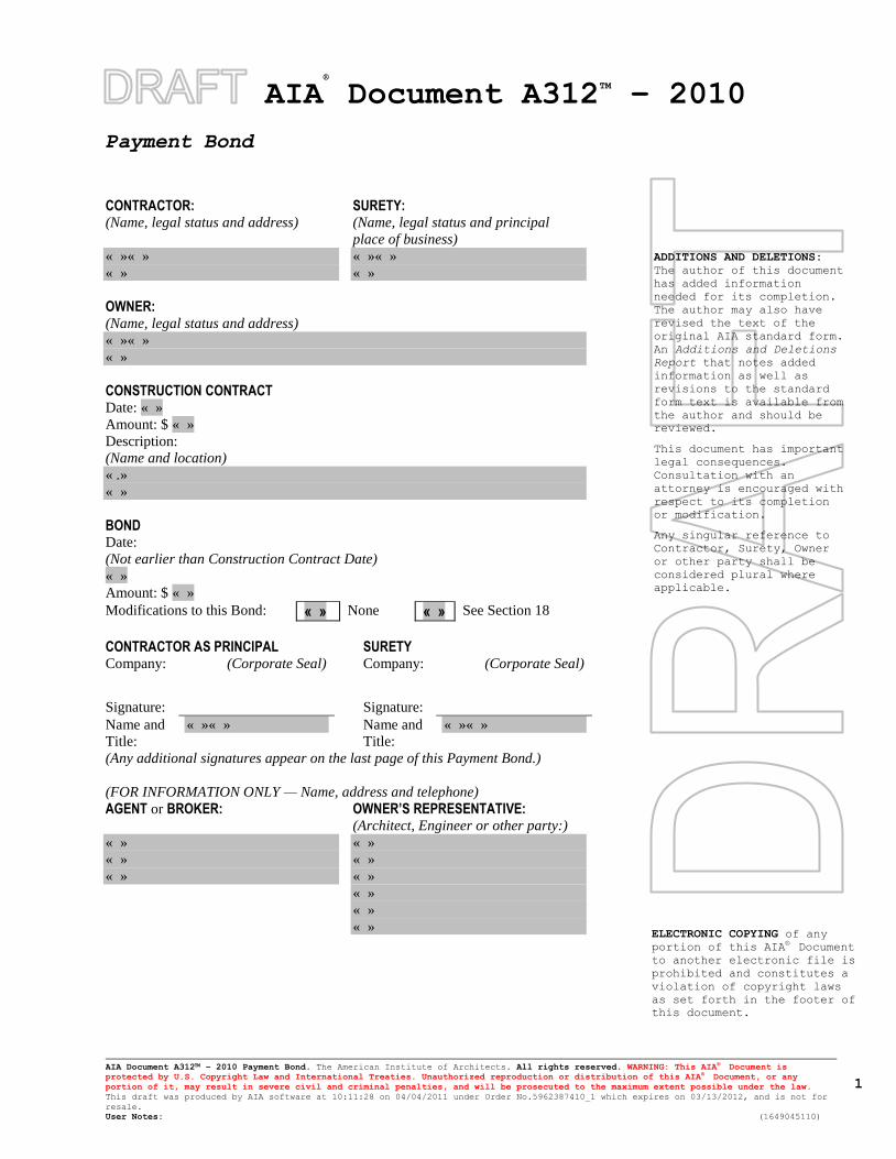
AIA®
Document A312TM
– 2010
Payment Bond
AIA Document A312™ – 2010 Payment Bond. The American Institute of Architects. All rights reserved. WARNING: This AIA® Document is
protected by U.S. Copyright Law and International Treaties. Unauthorized reproduction or distribution of this AIA® Document, or any
portion of it, may result in severe civil and criminal penalties, and will be prosecuted to the maximum extent possible under the law.
This draft was produced by AIA software at 10:11:28 on 04/04/2011 under Order No.5962387410_1 which expires on 03/13/2012, and is not for
resale.
User Notes: (1649045110)
1
ADDITIONS AND DELETIONS:
The author of this document
has added information
needed for its completion.
The author may also have
revised the text of the
original AIA standard form.
An Additions and Deletions
Report that notes added
information as well as
revisions to the standard
form text is available from
the author and should be
reviewed.
This document has important
legal consequences.
Consultation with an
attorney is encouraged with
respect to its completion
or modification.
Any singular reference to
Contractor, Surety, Owner
or other party shall be
considered plural where
applicable.
ELECTRONIC COPYING of any
portion of this AIA® Document
to another electronic file is
prohibited and constitutes a
violation of copyright laws
as set forth in the footer of
this document.
CONTRACTOR: (Name, legal status and address)
SURETY: (Name, legal status and principal
place of business)
« »« »
« »
« »« »
« »
OWNER: (Name, legal status and address)
« »« »
« »
CONSTRUCTION CONTRACT Date: « »
Amount: $ « »
Description:
(Name and location)
« .»
« »
BOND Date:
(Not earlier than Construction Contract Date)
« »
Amount: $ « »
Modifications to this Bond: « » None « » See Section 18
CONTRACTOR AS PRINCIPAL SURETY Company: (Corporate Seal) Company: (Corporate Seal)
Signature:
Signature:
Name and
Title:
« »« » Name and
Title:
« »« »
(Any additional signatures appear on the last page of this Payment Bond.)
(FOR INFORMATION ONLY — Name, address and telephone)
AGENT or BROKER:
OWNER’S REPRESENTATIVE: (Architect, Engineer or other party:)
« »
« »
« »
« »
« »
« »
« »
« »
« »
AIA Document A312™ – 2010 Payment Bond. The American Institute of Architects. All rights reserved. WARNING: This AIA® Document is
protected by U.S. Copyright Law and International Treaties. Unauthorized reproduction or distribution of this AIA® Document, or any
portion of it, may result in severe civil and criminal penalties, and will be prosecuted to the maximum extent possible under the law.
This draft was produced by AIA software at 10:11:28 on 04/04/2011 under Order No.5962387410_1 which expires on 03/13/2012, and is not for
resale.
User Notes: (1649045110)
2
§ 1 The Contractor and Surety, jointly and severally, bind themselves, their heirs, executors, administrators,
successors and assigns to the Owner to pay for labor, materials and equipment furnished for use in the performance
of the Construction Contract, which is incorporated herein by reference, subject to the following terms.
§ 2 If the Contractor promptly makes payment of all sums due to Claimants, and defends, indemnifies and holds
harmless the Owner from claims, demands, liens or suits by any person or entity seeking payment for labor,
materials or equipment furnished for use in the performance of the Construction Contract, then the Surety and the
Contractor shall have no obligation under this Bond.
§ 3 If there is no Owner Default under the Construction Contract, the Surety’s obligation to the Owner under this
Bond shall arise after the Owner has promptly notified the Contractor and the Surety (at the address described in
Section 13) of claims, demands, liens or suits against the Owner or the Owner’s property by any person or entity
seeking payment for labor, materials or equipment furnished for use in the performance of the Construction Contract
and tendered defense of such claims, demands, liens or suits to the Contractor and the Surety.
§ 4 When the Owner has satisfied the conditions in Section 3, the Surety shall promptly and at the Surety’s expense
defend, indemnify and hold harmless the Owner against a duly tendered claim, demand, lien or suit.
§ 5 The Surety’s obligations to a Claimant under this Bond shall arise after the following:
§ 5.1 Claimants, who do not have a direct contract with the Contractor,
.1 have furnished a written notice of non-payment to the Contractor, stating with substantial accuracy
the amount claimed and the name of the party to whom the materials were, or equipment was,
furnished or supplied or for whom the labor was done or performed, within ninety (90) days after
having last performed labor or last furnished materials or equipment included in the Claim; and
.2 have sent a Claim to the Surety (at the address described in Section 13).
§ 5.2 Claimants, who are employed by or have a direct contract with the Contractor, have sent a Claim to the Surety
(at the address described in Section 13).
§ 6 If a notice of non-payment required by Section 5.1.1 is given by the Owner to the Contractor, that is sufficient to
satisfy a Claimant’s obligation to furnish a written notice of non-payment under Section 5.1.1.
§ 7 When a Claimant has satisfied the conditions of Sections 5.1 or 5.2, whichever is applicable, the Surety shall
promptly and at the Surety’s expense take the following actions:
§ 7.1 Send an answer to the Claimant, with a copy to the Owner, within sixty (60) days after receipt of the Claim,
stating the amounts that are undisputed and the basis for challenging any amounts that are disputed; and
§ 7.2 Pay or arrange for payment of any undisputed amounts.
§ 7.3 The Surety’s failure to discharge its obligations under Section 7.1 or Section 7.2 shall not be deemed to
constitute a waiver of defenses the Surety or Contractor may have or acquire as to a Claim, except as to undisputed
amounts for which the Surety and Claimant have reached agreement. If, however, the Surety fails to discharge its
obligations under Section 7.1 or Section 7.2, the Surety shall indemnify the Claimant for the reasonable attorney’s
fees the Claimant incurs thereafter to recover any sums found to be due and owing to the Claimant.
§ 8 The Surety’s total obligation shall not exceed the amount of this Bond, plus the amount of reasonable attorney’s
fees provided under Section 7.3, and the amount of this Bond shall be credited for any payments made in good faith
by the Surety.
§ 9 Amounts owed by the Owner to the Contractor under the Construction Contract shall be used for the
performance of the Construction Contract and to satisfy claims, if any, under any construction performance bond.
By the Contractor furnishing and the Owner accepting this Bond, they agree that all funds earned by the Contractor
in the performance of the Construction Contract are dedicated to satisfy obligations of the Contractor and Surety
under this Bond, subject to the Owner’s priority to use the funds for the completion of the work.
AIA Document A312™ – 2010 Payment Bond. The American Institute of Architects. All rights reserved. WARNING: This AIA® Document is
protected by U.S. Copyright Law and International Treaties. Unauthorized reproduction or distribution of this AIA® Document, or any
portion of it, may result in severe civil and criminal penalties, and will be prosecuted to the maximum extent possible under the law.
This draft was produced by AIA software at 10:11:28 on 04/04/2011 under Order No.5962387410_1 which expires on 03/13/2012, and is not for
resale.
User Notes: (1649045110)
3
§ 10 The Surety shall not be liable to the Owner, Claimants or others for obligations of the Contractor that are
unrelated to the Construction Contract. The Owner shall not be liable for the payment of any costs or expenses of
any Claimant under this Bond, and shall have under this Bond no obligation to make payments to, or give notice on
behalf of, Claimants or otherwise have any obligations to Claimants under this Bond.
§ 11 The Surety hereby waives notice of any change, including changes of time, to the Construction Contract or to
related subcontracts, purchase orders and other obligations.
§ 12 No suit or action shall be commenced by a Claimant under this Bond other than in a court of competent
jurisdiction in the state in which the project that is the subject of the Construction Contract is located or after the
expiration of one year from the date (1) on which the Claimant sent a Claim to the Surety pursuant to Section 5.1.2
or 5.2, or (2) on which the last labor or service was performed by anyone or the last materials or equipment were
furnished by anyone under the Construction Contract, whichever of (1) or (2) first occurs. If the provisions of this
Paragraph are void or prohibited by law, the minimum period of limitation available to sureties as a defense in the
jurisdiction of the suit shall be applicable.
§ 13 Notice and Claims to the Surety, the Owner or the Contractor shall be mailed or delivered to the address shown
on the page on which their signature appears. Actual receipt of notice or Claims, however accomplished, shall be
sufficient compliance as of the date received.
§ 14 When this Bond has been furnished to comply with a statutory or other legal requirement in the location where
the construction was to be performed, any provision in this Bond conflicting with said statutory or legal requirement
shall be deemed deleted herefrom and provisions conforming to such statutory or other legal requirement shall be
deemed incorporated herein. When so furnished, the intent is that this Bond shall be construed as a statutory bond
and not as a common law bond.
§ 15 Upon request by any person or entity appearing to be a potential beneficiary of this Bond, the Contractor and
Owner shall promptly furnish a copy of this Bond or shall permit a copy to be made.
§ 16 Definitions § 16.1 Claim. A written statement by the Claimant including at a minimum:
.1 the name of the Claimant;
.2 the name of the person for whom the labor was done, or materials or equipment furnished;
.3 a copy of the agreement or purchase order pursuant to which labor, materials or equipment was
furnished for use in the performance of the Construction Contract;
.4 a brief description of the labor, materials or equipment furnished;
.5 the date on which the Claimant last performed labor or last furnished materials or equipment for use
in the performance of the Construction Contract;
.6 the total amount earned by the Claimant for labor, materials or equipment furnished as of the date of
the Claim;
.7 the total amount of previous payments received by the Claimant; and
.8 the total amount due and unpaid to the Claimant for labor, materials or equipment furnished as of the
date of the Claim.
§ 16.2 Claimant. An individual or entity having a direct contract with the Contractor or with a subcontractor of the
Contractor to furnish labor, materials or equipment for use in the performance of the Construction Contract. The
term Claimant also includes any individual or entity that has rightfully asserted a claim under an applicable
mechanic’s lien or similar statute against the real property upon which the Project is located. The intent of this Bond
shall be to include without limitation in the terms “labor, materials or equipment” that part of water, gas, power,
light, heat, oil, gasoline, telephone service or rental equipment used in the Construction Contract, architectural and
engineering services required for performance of the work of the Contractor and the Contractor’s subcontractors,
and all other items for which a mechanic's lien may be asserted in the jurisdiction where the labor, materials or
equipment were furnished.
§ 16.3 Construction Contract. The agreement between the Owner and Contractor identified on the cover page,
including all Contract Documents and all changes made to the agreement and the Contract Documents.
AIA Document A312™ – 2010 Payment Bond. The American Institute of Architects. All rights reserved. WARNING: This AIA® Document is
protected by U.S. Copyright Law and International Treaties. Unauthorized reproduction or distribution of this AIA® Document, or any
portion of it, may result in severe civil and criminal penalties, and will be prosecuted to the maximum extent possible under the law.
This draft was produced by AIA software at 10:11:28 on 04/04/2011 under Order No.5962387410_1 which expires on 03/13/2012, and is not for
resale.
User Notes: (1649045110)
4
§ 16.4 Owner Default. Failure of the Owner, which has not been remedied or waived, to pay the Contractor as
required under the Construction Contract or to perform and complete or comply with the other material terms of the
Construction Contract.
§ 16.5 Contract Documents. All the documents that comprise the agreement between the Owner and Contractor.
§ 17 If this Bond is issued for an agreement between a Contractor and subcontractor, the term Contractor in this
Bond shall be deemed to be Subcontractor and the term Owner shall be deemed to be Contractor.
§ 18 Modifications to this bond are as follows:
« »
(Space is provided below for additional signatures of added parties, other than those appearing on the cover page.)
CONTRACTOR AS PRINCIPAL SURETY Company: (Corporate Seal) Company: (Corporate Seal)
Signature:
Signature:
Name and Title: « »« » Name and Title: « »« »
Address: « » Address: « »
Drinking Water System Replacement at USA # 2015-077
Voorhees High School
for the NHVRHSD
CERTIFICATE OF INSURANCE STATEMENT 00 62 16 - 1 2015 USA Architects Planners + Interior Designers, PA
00 62 16 - CERTIFICATE OF INSURANCE STATEMENT
NORTH HUNTERDON-VOORHEES HIGH SCHOOL DISTRICT
The Bidder fully understands the North Hunterdon-Voorhees High School District insurance
requirements as stated in the Supplementary General Conditions and agrees to provide all insurance
required by these documents prior to award of contract.
_______________________________
BIDDER – Signature
_______________________________
BIDDER – Print Name
END OF SECTION 00 62 16

Drinking Water System Replacement at USA # 2015-077
Voorhees High School
for the NHVRHSD
GENERAL CONDITIONS 00 72 00-1 2015 USA Architects Planners + Interior Designers, PA
SECTION 00 72 00 - GENERAL CONDITIONS OF THE CONTRACT FOR CONSTRUCTION
The General Conditions of this Contract is the American Institute of Architect's Document A201
“General Conditions of the Contract for Construction”, 2007 Edition, Is bound herewith.
The General Conditions shall be in effect for the duration of this project for all contractors.
Document A201 is enclosed (38 pages) following for each Prime Contractor’s review.
END OF SECTION 00 72 00

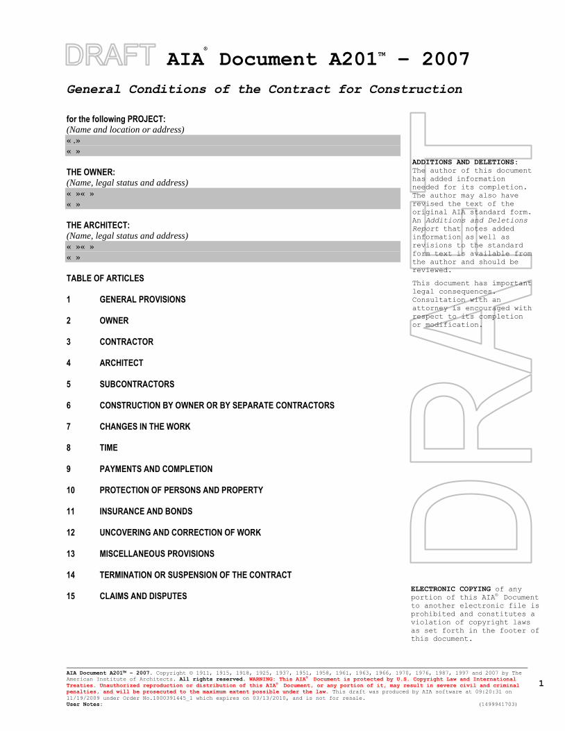
AIA®
Document A201TM
– 2007
General Conditions of the Contract for Construction
AIA Document A201™ – 2007. Copyright © 1911, 1915, 1918, 1925, 1937, 1951, 1958, 1961, 1963, 1966, 1970, 1976, 1987, 1997 and 2007 by The
American Institute of Architects. All rights reserved. WARNING: This AIA® Document is protected by U.S. Copyright Law and International
Treaties. Unauthorized reproduction or distribution of this AIA® Document, or any portion of it, may result in severe civil and criminal
penalties, and will be prosecuted to the maximum extent possible under the law. This draft was produced by AIA software at 09:20:31 on
11/19/2009 under Order No.1000391445_1 which expires on 03/13/2010, and is not for resale.
User Notes: (1499941703)
1
ADDITIONS AND DELETIONS:
The author of this document
has added information
needed for its completion.
The author may also have
revised the text of the
original AIA standard form.
An Additions and Deletions
Report that notes added
information as well as
revisions to the standard
form text is available from
the author and should be
reviewed.
This document has important
legal consequences.
Consultation with an
attorney is encouraged with
respect to its completion
or modification.
ELECTRONIC COPYING of any
portion of this AIA® Document
to another electronic file is
prohibited and constitutes a
violation of copyright laws
as set forth in the footer of
this document.
for the following PROJECT: (Name and location or address)
« .»
« »
THE OWNER: (Name, legal status and address)
« »« »
« »
THE ARCHITECT: (Name, legal status and address)
« »« »
« »
TABLE OF ARTICLES 1 GENERAL PROVISIONS 2 OWNER 3 CONTRACTOR 4 ARCHITECT 5 SUBCONTRACTORS 6 CONSTRUCTION BY OWNER OR BY SEPARATE CONTRACTORS 7 CHANGES IN THE WORK 8 TIME 9 PAYMENTS AND COMPLETION 10 PROTECTION OF PERSONS AND PROPERTY 11 INSURANCE AND BONDS 12 UNCOVERING AND CORRECTION OF WORK 13 MISCELLANEOUS PROVISIONS 14 TERMINATION OR SUSPENSION OF THE CONTRACT 15 CLAIMS AND DISPUTES
AIA Document A201™ – 2007. Copyright © 1911, 1915, 1918, 1925, 1937, 1951, 1958, 1961, 1963, 1966, 1970, 1976, 1987, 1997 and 2007 by The
American Institute of Architects. All rights reserved. WARNING: This AIA® Document is protected by U.S. Copyright Law and International
Treaties. Unauthorized reproduction or distribution of this AIA® Document, or any portion of it, may result in severe civil and criminal
penalties, and will be prosecuted to the maximum extent possible under the law. This draft was produced by AIA software at 09:20:31 on
11/19/2009 under Order No.1000391445_1 which expires on 03/13/2010, and is not for resale.
User Notes: (1499941703)
2
INDEX (Topics and numbers in bold are section headings.)
Acceptance of Nonconforming Work
9.6.6, 9.9.3, 12.3
Acceptance of Work
9.6.6, 9.8.2, 9.9.3, 9.10.1, 9.10.3, 12.3
Access to Work
3.16, 6.2.1, 12.1
Accident Prevention
10
Acts and Omissions
3.2, 3.3.2, 3.12.8, 3.18, 4.2.3, 8.3.1, 9.5.1, 10.2.5,
10.2.8, 13.4.2, 13.7, 14.1, 15.2
Addenda
1.1.1, 3.11.1
Additional Costs, Claims for
3.7.4, 3.7.5, 6.1.1, 7.3.7.5, 10.3, 15.1.4
Additional Inspections and Testing
9.4.2, 9.8.3, 12.2.1, 13.5
Additional Insured
11.1.4
Additional Time, Claims for
3.2.4, 3.7.4, 3.7.5, 3.10.2, 8.3.2, 15.1.5
Administration of the Contract
3.1.3, 4.2, 9.4, 9.5
Advertisement or Invitation to Bid
1.1.1
Aesthetic Effect
4.2.13
Allowances
3.8, 7.3.8
All-risk Insurance
11.3.1, 11.3.1.1
Applications for Payment
4.2.5, 7.3.9, 9.2, 9.3, 9.4, 9.5.1, 9.6.3, 9.7, 9.10,
11.1.3
Approvals
2.1.1, 2.2.2, 2.4, 3.1.3, 3.10.2, 3.12.8, 3.12.9, 3.12.10,
4.2.7, 9.3.2, 13.5.1
Arbitration
8.3.1, 11.3.10, 13.1.1, 15.3.2, 15.4
ARCHITECT
4
Architect, Definition of
4.1.1
Architect, Extent of Authority
2.4.1, 3.12.7, 4.1, 4.2, 5.2, 6.3, 7.1.2, 7.3.7, 7.4, 9.2,
9.3.1, 9.4, 9.5, 9.6.3, 9.8, 9.10.1, 9.10.3, 12.1, 12.2.1,
13.5.1, 13.5.2, 14.2.2, 14.2.4, 15.1.3, 15.2.1
Architect, Limitations of Authority and
Responsibility
2.1.1, 3.12.4, 3.12.8, 3.12.10, 4.1.2, 4.2.1, 4.2.2,
4.2.3, 4.2.6, 4.2.7, 4.2.10, 4.2.12, 4.2.13, 5.2.1, 7.4,
9.4.2, 9.5.3, 9.6.4, 15.1.3, 15.2
Architect’s Additional Services and Expenses
2.4.1, 11.3.1.1, 12.2.1, 13.5.2, 13.5.3, 14.2.4
Architect’s Administration of the Contract
3.1.3, 4.2, 3.7.4, 15.2, 9.4.1, 9.5
Architect’s Approvals
2.4.1, 3.1.3, 3.5, 3.10.2, 4.2.7
Architect’s Authority to Reject Work
3.5, 4.2.6, 12.1.2, 12.2.1
Architect’s Copyright
1.1.7, 1.5
Architect’s Decisions
3.7.4, 4.2.6, 4.2.7, 4.2.11, 4.2.12, 4.2.13, 4.2.14, 6.3,
7.3.7, 7.3.9, 8.1.3, 8.3.1, 9.2, 9.4.1, 9.5, 9.8.4, 9.9.1,
13.5.2, 15.2, 15.3
Architect’s Inspections
3.7.4, 4.2.2, 4.2.9, 9.4.2, 9.8.3, 9.9.2, 9.10.1, 13.5
Architect’s Instructions
3.2.4, 3.3.1, 4.2.6, 4.2.7, 13.5.2
Architect’s Interpretations
4.2.11, 4.2.12
Architect’s Project Representative
4.2.10
Architect’s Relationship with Contractor
1.1.2, 1.5, 3.1.3, 3.2.2, 3.2.3, 3.2.4, 3.3.1, 3.4.2, 3.5,
3.7.4, 3.7.5, 3.9.2, 3.9.3, 3.10, 3.11, 3.12, 3.16, 3.18,
4.1.2, 4.1.3, 4.2, 5.2, 6.2.2, 7, 8.3.1, 9.2, 9.3, 9.4, 9.5,
9.7, 9.8, 9.9, 10.2.6, 10.3, 11.3.7, 12, 13.4.2, 13.5,
15.2
Architect’s Relationship with Subcontractors
1.1.2, 4.2.3, 4.2.4, 4.2.6, 9.6.3, 9.6.4, 11.3.7
Architect’s Representations
9.4.2, 9.5.1, 9.10.1
Architect’s Site Visits
3.7.4, 4.2.2, 4.2.9, 9.4.2, 9.5.1, 9.9.2, 9.10.1, 13.5
Asbestos
10.3.1
Attorneys’ Fees
3.18.1, 9.10.2, 10.3.3
Award of Separate Contracts
6.1.1, 6.1.2
Award of Subcontracts and Other Contracts for
Portions of the Work
5.2
Basic Definitions
1.1
Bidding Requirements
1.1.1, 5.2.1, 11.4.1
Binding Dispute Resolution
9.7, 11.3.9, 11.3.10, 13.1.1, 15.2.5, 15.2.6.1, 15.3.1,
15.3.2, 15.4.1
Boiler and Machinery Insurance
11.3.2
Bonds, Lien
7.3.7.4, 9.10.2, 9.10.3
Bonds, Performance, and Payment
7.3.7.4, 9.6.7, 9.10.3, 11.3.9, 11.4
AIA Document A201™ – 2007. Copyright © 1911, 1915, 1918, 1925, 1937, 1951, 1958, 1961, 1963, 1966, 1970, 1976, 1987, 1997 and 2007 by The
American Institute of Architects. All rights reserved. WARNING: This AIA® Document is protected by U.S. Copyright Law and International
Treaties. Unauthorized reproduction or distribution of this AIA® Document, or any portion of it, may result in severe civil and criminal
penalties, and will be prosecuted to the maximum extent possible under the law. This draft was produced by AIA software at 09:20:31 on
11/19/2009 under Order No.1000391445_1 which expires on 03/13/2010, and is not for resale.
User Notes: (1499941703)
3
Building Permit
3.7.1
Capitalization
1.3
Certificate of Substantial Completion
9.8.3, 9.8.4, 9.8.5
Certificates for Payment
4.2.1, 4.2.5, 4.2.9, 9.3.3, 9.4, 9.5, 9.6.1, 9.6.6, 9.7,
9.10.1, 9.10.3, 14.1.1.3, 14.2.4, 15.1.3
Certificates of Inspection, Testing or Approval
13.5.4
Certificates of Insurance
9.10.2, 11.1.3
Change Orders
1.1.1, 2.4.1, 3.4.2, 3.7.4, 3.8.2.3, 3.11.1, 3.12.8, 4.2.8,
5.2.3, 7.1.2, 7.1.3, 7.2, 7.3.2, 7.3.6, 7.3.9, 7.3.10,
8.3.1, 9.3.1.1, 9.10.3, 10.3.2, 11.3.1.2, 11.3.4, 11.3.9,
12.1.2, 15.1.3
Change Orders, Definition of
7.2.1
CHANGES IN THE WORK
2.2.1, 3.11, 4.2.8, 7, 7.2.1, 7.3.1, 7.4, 7.4.1, 8.3.1,
9.3.1.1, 11.3.9
Claims, Definition of
15.1.1
CLAIMS AND DISPUTES
3.2.4, 6.1.1, 6.3, 7.3.9, 9.3.3, 9.10.4, 10.3.3, 15, 15.4
Claims and Timely Assertion of Claims
15.4.1
Claims for Additional Cost
3.2.4, 3.7.4, 6.1.1, 7.3.9, 10.3.2, 15.1.4
Claims for Additional Time
3.2.4, 3.7.46.1.1, 8.3.2, 10.3.2, 15.1.5
Concealed or Unknown Conditions, Claims for
3.7.4
Claims for Damages
3.2.4, 3.18, 6.1.1, 8.3.3, 9.5.1, 9.6.7, 10.3.3, 11.1.1,
11.3.5, 11.3.7, 14.1.3, 14.2.4, 15.1.6
Claims Subject to Arbitration
15.3.1, 15.4.1
Cleaning Up
3.15, 6.3
Commencement of the Work, Conditions Relating to
2.2.1, 3.2.2, 3.4.1, 3.7.1, 3.10.1, 3.12.6, 5.2.1, 5.2.3,
6.2.2, 8.1.2, 8.2.2, 8.3.1, 11.1, 11.3.1, 11.3.6, 11.4.1,
15.1.4
Commencement of the Work, Definition of
8.1.2
Communications Facilitating Contract
Administration
3.9.1, 4.2.4
Completion, Conditions Relating to
3.4.1, 3.11, 3.15, 4.2.2, 4.2.9, 8.2, 9.4.2, 9.8, 9.9.1,
9.10, 12.2, 13.7, 14.1.2
COMPLETION, PAYMENTS AND
9
Completion, Substantial
4.2.9, 8.1.1, 8.1.3, 8.2.3, 9.4.2, 9.8, 9.9.1, 9.10.3,
12.2, 13.7
Compliance with Laws
1.6.1, 3.2.3, 3.6, 3.7, 3.12.10, 3.13, 4.1.1, 9.6.4,
10.2.2, 11.1, 11.3, 13.1, 13.4, 13.5.1, 13.5.2, 13.6,
14.1.1, 14.2.1.3, 15.2.8, 15.4.2, 15.4.3
Concealed or Unknown Conditions
3.7.4, 4.2.8, 8.3.1, 10.3
Conditions of the Contract
1.1.1, 6.1.1, 6.1.4
Consent, Written
3.4.2, 3.7.4, 3.12.8, 3.14.2, 4.1.2, 9.3.2, 9.8.5, 9.9.1,
9.10.2, 9.10.3, 11.3.1, 13.2, 13.4.2, 15.4.4.2
Consolidation or Joinder
15.4.4
CONSTRUCTION BY OWNER OR BY
SEPARATE CONTRACTORS
1.1.4, 6
Construction Change Directive, Definition of
7.3.1
Construction Change Directives
1.1.1, 3.4.2, 3.12.8, 4.2.8, 7.1.1, 7.1.2, 7.1.3, 7.3,
9.3.1.1
Construction Schedules, Contractor’s
3.10, 3.12.1, 3.12.2, 6.1.3, 15.1.5.2
Contingent Assignment of Subcontracts
5.4, 14.2.2.2
Continuing Contract Performance
15.1.3
Contract, Definition of
1.1.2
CONTRACT, TERMINATION OR
SUSPENSION OF THE
5.4.1.1, 11.3.9, 14
Contract Administration
3.1.3, 4, 9.4, 9.5
Contract Award and Execution, Conditions Relating
to
3.7.1, 3.10, 5.2, 6.1, 11.1.3, 11.3.6, 11.4.1
Contract Documents, Copies Furnished and Use of
1.5.2, 2.2.5, 5.3
Contract Documents, Definition of
1.1.1
Contract Sum
3.7.4, 3.8, 5.2.3, 7.2, 7.3, 7.4, 9.1, 9.4.2, 9.5.1.4,
9.6.7, 9.7, 10.3.2, 11.3.1, 14.2.4, 14.3.2, 15.1.4,
15.2.5
Contract Sum, Definition of
9.1
Contract Time
3.7.4, 3.7.5, 3.10.2, 5.2.3, 7.2.1.3, 7.3.1, 7.3.5, 7.4,
8.1.1, 8.2.1, 8.3.1, 9.5.1, 9.7, 10.3.2, 12.1.1, 14.3.2,
15.1.5.1, 15.2.5
Contract Time, Definition of
8.1.1
CONTRACTOR
3
AIA Document A201™ – 2007. Copyright © 1911, 1915, 1918, 1925, 1937, 1951, 1958, 1961, 1963, 1966, 1970, 1976, 1987, 1997 and 2007 by The
American Institute of Architects. All rights reserved. WARNING: This AIA® Document is protected by U.S. Copyright Law and International
Treaties. Unauthorized reproduction or distribution of this AIA® Document, or any portion of it, may result in severe civil and criminal
penalties, and will be prosecuted to the maximum extent possible under the law. This draft was produced by AIA software at 09:20:31 on
11/19/2009 under Order No.1000391445_1 which expires on 03/13/2010, and is not for resale.
User Notes: (1499941703)
4
Contractor, Definition of
3.1, 6.1.2
Contractor’s Construction Schedules
3.10, 3.12.1, 3.12.2, 6.1.3, 15.1.5.2
Contractor’s Employees
3.3.2, 3.4.3, 3.8.1, 3.9, 3.18.2, 4.2.3, 4.2.6, 10.2, 10.3,
11.1.1, 11.3.7, 14.1, 14.2.1.1,
Contractor’s Liability Insurance
11.1
Contractor’s Relationship with Separate Contractors
and Owner’s Forces
3.12.5, 3.14.2, 4.2.4, 6, 11.3.7, 12.1.2, 12.2.4
Contractor’s Relationship with Subcontractors
1.2.2, 3.3.2, 3.18.1, 3.18.2, 5, 9.6.2, 9.6.7, 9.10.2,
11.3.1.2, 11.3.7, 11.3.8
Contractor’s Relationship with the Architect
1.1.2, 1.5, 3.1.3, 3.2.2, 3.2.3, 3.2.4, 3.3.1, 3.4.2, 3.5,
3.7.4, 3.10, 3.11, 3.12, 3.16, 3.18, 4.1.3, 4.2, 5.2,
6.2.2, 7, 8.3.1, 9.2, 9.3, 9.4, 9.5, 9.7, 9.8, 9.9, 10.2.6,
10.3, 11.3.7, 12, 13.5, 15.1.2, 15.2.1
Contractor’s Representations
3.2.1, 3.2.2, 3.5, 3.12.6, 6.2.2, 8.2.1, 9.3.3, 9.8.2
Contractor’s Responsibility for Those Performing the
Work
3.3.2, 3.18, 5.3.1, 6.1.3, 6.2, 9.5.1, 10.2.8
Contractor’s Review of Contract Documents
3.2
Contractor’s Right to Stop the Work
9.7
Contractor’s Right to Terminate the Contract
14.1, 15.1.6
Contractor’s Submittals
3.10, 3.11, 3.12.4, 4.2.7, 5.2.1, 5.2.3, 9.2, 9.3, 9.8.2,
9.8.3, 9.9.1, 9.10.2, 9.10.3, 11.1.3, 11.4.2
Contractor’s Superintendent
3.9, 10.2.6
Contractor’s Supervision and Construction
Procedures
1.2.2, 3.3, 3.4, 3.12.10, 4.2.2, 4.2.7, 6.1.3, 6.2.4,
7.1.3, 7.3.5, 7.3.7, 8.2, 10, 12, 14, 15.1.3
Contractual Liability Insurance
11.1.1.8, 11.2
Coordination and Correlation
1.2, 3.2.1, 3.3.1, 3.10, 3.12.6, 6.1.3, 6.2.1
Copies Furnished of Drawings and Specifications
1.5, 2.2.5, 3.11
Copyrights
1.5, 3.17
Correction of Work
2.3, 2.4, 3.7.3, 9.4.2, 9.8.2, 9.8.3, 9.9.1, 12.1.2, 12.2
Correlation and Intent of the Contract Documents
1.2
Cost, Definition of
7.3.7
Costs
2.4.1, 3.2.4, 3.7.3, 3.8.2, 3.15.2, 5.4.2, 6.1.1, 6.2.3,
7.3.3.3, 7.3.7, 7.3.8, 7.3.9, 9.10.2, 10.3.2, 10.3.6,
11.3, 12.1.2, 12.2.1, 12.2.4, 13.5, 14
Cutting and Patching
3.14, 6.2.5
Damage to Construction of Owner or Separate
Contractors
3.14.2, 6.2.4, 10.2.1.2, 10.2.5, 10.4, 11.1.1, 11.3,
12.2.4
Damage to the Work
3.14.2, 9.9.1, 10.2.1.2, 10.2.5, 10.4.1, 11.3.1, 12.2.4
Damages, Claims for
3.2.4, 3.18, 6.1.1, 8.3.3, 9.5.1, 9.6.7, 10.3.3, 11.1.1,
11.3.5, 11.3.7, 14.1.3, 14.2.4, 15.1.6
Damages for Delay
6.1.1, 8.3.3, 9.5.1.6, 9.7, 10.3.2
Date of Commencement of the Work, Definition of
8.1.2
Date of Substantial Completion, Definition of
8.1.3
Day, Definition of
8.1.4
Decisions of the Architect
3.7.4, 4.2.6, 4.2.7, 4.2.11, 4.2.12, 4.2.13, 15.2, 6.3,
7.3.7, 7.3.9, 8.1.3, 8.3.1, 9.2, 9.4, 9.5.1, 9.8.4, 9.9.1,
13.5.2, 14.2.2, 14.2.4, 15.1, 15.2
Decisions to Withhold Certification
9.4.1, 9.5, 9.7, 14.1.1.3
Defective or Nonconforming Work, Acceptance,
Rejection and Correction of
2.3.1, 2.4.1, 3.5, 4.2.6, 6.2.5, 9.5.1, 9.5.2, 9.6.6, 9.8.2,
9.9.3, 9.10.4, 12.2.1
Definitions
1.1, 2.1.1, 3.1.1, 3.5, 3.12.1, 3.12.2, 3.12.3, 4.1.1,
15.1.1, 5.1, 6.1.2, 7.2.1, 7.3.1, 8.1, 9.1, 9.8.1
Delays and Extensions of Time
3.2, 3.7.4, 5.2.3, 7.2.1, 7.3.1, 7.4, 8.3, 9.5.1, 9.7,
10.3.2, 10.4.1, 14.3.2, 15.1.5, 15.2.5
Disputes
6.3, 7.3.9, 15.1, 15.2
Documents and Samples at the Site
3.11
Drawings, Definition of
1.1.5
Drawings and Specifications, Use and Ownership of
3.11
Effective Date of Insurance
8.2.2, 11.1.2
Emergencies
10.4, 14.1.1.2, 15.1.4
Employees, Contractor’s
3.3.2, 3.4.3, 3.8.1, 3.9, 3.18.2, 4.2.3, 4.2.6, 10.2,
10.3.3, 11.1.1, 11.3.7, 14.1, 14.2.1.1
Equipment, Labor, Materials or
1.1.3, 1.1.6, 3.4, 3.5, 3.8.2, 3.8.3, 3.12, 3.13.1, 3.15.1,
4.2.6, 4.2.7, 5.2.1, 6.2.1, 7.3.7, 9.3.2, 9.3.3, 9.5.1.3,
9.10.2, 10.2.1, 10.2.4, 14.2.1.1, 14.2.1.2
Execution and Progress of the Work
1.1.3, 1.2.1, 1.2.2, 2.2.3, 2.2.5, 3.1, 3.3.1, 3.4.1, 3.5,
3.7.1, 3.10.1, 3.12, 3.14, 4.2, 6.2.2, 7.1.3, 7.3.5, 8.2,
9.5.1, 9.9.1, 10.2, 10.3, 12.2, 14.2, 14.3.1, 15.1.3
AIA Document A201™ – 2007. Copyright © 1911, 1915, 1918, 1925, 1937, 1951, 1958, 1961, 1963, 1966, 1970, 1976, 1987, 1997 and 2007 by The
American Institute of Architects. All rights reserved. WARNING: This AIA® Document is protected by U.S. Copyright Law and International
Treaties. Unauthorized reproduction or distribution of this AIA® Document, or any portion of it, may result in severe civil and criminal
penalties, and will be prosecuted to the maximum extent possible under the law. This draft was produced by AIA software at 09:20:31 on
11/19/2009 under Order No.1000391445_1 which expires on 03/13/2010, and is not for resale.
User Notes: (1499941703)
5
Extensions of Time
3.2.4, 3.7.4, 5.2.3, 7.2.1, 7.3, 7.4, 9.5.1, 9.7, 10.3.2,
10.4.1, 14.3, 15.1.5, 15.2.5
Failure of Payment
9.5.1.3, 9.7, 9.10.2, 13.6, 14.1.1.3, 14.2.1.2
Faulty Work
(See Defective or Nonconforming Work)
Final Completion and Final Payment
4.2.1, 4.2.9, 9.8.2, 9.10, 11.1.2, 11.1.3, 11.3.1, 11.3.5,
12.3.1, 14.2.4, 14.4.3
Financial Arrangements, Owner’s
2.2.1, 13.2.2, 14.1.1.4
Fire and Extended Coverage Insurance
11.3.1.1
GENERAL PROVISIONS
1
Governing Law
13.1
Guarantees (See Warranty)
Hazardous Materials
10.2.4, 10.3
Identification of Subcontractors and Suppliers
5.2.1
Indemnification
3.17, 3.18, 9.10.2, 10.3.3, 10.3.5, 10.3.6, 11.3.1.2,
11.3.7
Information and Services Required of the Owner
2.1.2, 2.2, 3.2.2, 3.12.4, 3.12.10, 6.1.3, 6.1.4, 6.2.5,
9.6.1, 9.6.4, 9.9.2, 9.10.3, 10.3.3, 11.2, 11.4, 13.5.1,
13.5.2, 14.1.1.4, 14.1.4, 15.1.3
Initial Decision
15.2
Initial Decision Maker, Definition of
1.1.8
Initial Decision Maker, Decisions
14.2.2, 14.2.4, 15.2.1, 15.2.2, 15.2.3, 15.2.4, 15.2.5
Initial Decision Maker, Extent of Authority
14.2.2, 14.2.4, 15.1.3, 15.2.1, 15.2.2, 15.2.3, 15.2.4,
15.2.5
Injury or Damage to Person or Property
10.2.8, 10.4.1
Inspections
3.1.3, 3.3.3, 3.7.1, 4.2.2, 4.2.6, 4.2.9, 9.4.2, 9.8.3,
9.9.2, 9.10.1, 12.2.1, 13.5
Instructions to Bidders
1.1.1
Instructions to the Contractor
3.2.4, 3.3.1, 3.8.1, 5.2.1, 7, 8.2.2, 12, 13.5.2
Instruments of Service, Definition of
1.1.7
Insurance
3.18.1, 6.1.1, 7.3.7, 9.3.2, 9.8.4, 9.9.1, 9.10.2, 11
Insurance, Boiler and Machinery
11.3.2
Insurance, Contractor’s Liability
11.1
Insurance, Effective Date of
8.2.2, 11.1.2
Insurance, Loss of Use
11.3.3
Insurance, Owner’s Liability
11.2
Insurance, Property
10.2.5, 11.3
Insurance, Stored Materials
9.3.2
INSURANCE AND BONDS
11
Insurance Companies, Consent to Partial Occupancy
9.9.1
Intent of the Contract Documents
1.2.1, 4.2.7, 4.2.12, 4.2.13, 7.4
Interest
13.6
Interpretation
1.2.3, 1.4, 4.1.1, 5.1, 6.1.2, 15.1.1
Interpretations, Written
4.2.11, 4.2.12, 15.1.4
Judgment on Final Award
15.4.2
Labor and Materials, Equipment
1.1.3, 1.1.6, 3.4, 3.5, 3.8.2, 3.8.3, 3.12, 3.13, 3.15.1,
4.2.6, 4.2.7, 5.2.1, 6.2.1, 7.3.7, 9.3.2, 9.3.3, 9.5.1.3,
9.10.2, 10.2.1, 10.2.4, 14.2.1.1, 14.2.1.2
Labor Disputes
8.3.1
Laws and Regulations
1.5, 3.2.3, 3.6, 3.7, 3.12.10, 3.13.1, 4.1.1, 9.6.4, 9.9.1,
10.2.2, 11.1.1, 11.3, 13.1.1, 13.4, 13.5.1, 13.5.2,
13.6.1, 14, 15.2.8, 15.4
Liens
2.1.2, 9.3.3, 9.10.2, 9.10.4, 15.2.8
Limitations, Statutes of
12.2.5, 13.7, 15.4.1.1
Limitations of Liability
2.3.1, 3.2.2, 3.5, 3.12.10, 3.17, 3.18.1, 4.2.6, 4.2.7,
4.2.12, 6.2.2, 9.4.2, 9.6.4, 9.6.7, 10.2.5, 10.3.3,
11.1.2, 11.2, 11.3.7, 12.2.5, 13.4.2
Limitations of Time
2.1.2, 2.2, 2.4, 3.2.2, 3.10, 3.11, 3.12.5, 3.15.1, 4.2.7,
5.2, 5.3.1, 5.4.1, 6.2.4, 7.3, 7.4, 8.2, 9.2, 9.3.1, 9.3.3,
9.4.1, 9.5, 9.6, 9.7, 9.8, 9.9, 9.10, 11.1.3, 11.3.1.5,
11.3.6, 11.3.10, 12.2, 13.5, 13.7, 14, 15
Loss of Use Insurance
11.3.3
Material Suppliers
1.5, 3.12.1, 4.2.4, 4.2.6, 5.2.1, 9.3, 9.4.2, 9.6, 9.10.5
Materials, Hazardous
10.2.4, 10.3
Materials, Labor, Equipment and
1.1.3, 1.1.6, 1.5.1, 3.4.1, 3.5, 3.8.2, 3.8.3, 3.12,
3.13.1, 3.15.1, 4.2.6, 4.2.7, 5.2.1, 6.2.1, 7.3.7, 9.3.2,
9.3.3, 9.5.1.3, 9.10.2, 10.2.1.2, 10.2.4, 14.2.1.1,
14.2.1.2
AIA Document A201™ – 2007. Copyright © 1911, 1915, 1918, 1925, 1937, 1951, 1958, 1961, 1963, 1966, 1970, 1976, 1987, 1997 and 2007 by The
American Institute of Architects. All rights reserved. WARNING: This AIA® Document is protected by U.S. Copyright Law and International
Treaties. Unauthorized reproduction or distribution of this AIA® Document, or any portion of it, may result in severe civil and criminal
penalties, and will be prosecuted to the maximum extent possible under the law. This draft was produced by AIA software at 09:20:31 on
11/19/2009 under Order No.1000391445_1 which expires on 03/13/2010, and is not for resale.
User Notes: (1499941703)
6
Means, Methods, Techniques, Sequences and
Procedures of Construction
3.3.1, 3.12.10, 4.2.2, 4.2.7, 9.4.2
Mechanic’s Lien
2.1.2, 15.2.8
Mediation
8.3.1, 10.3.5, 10.3.6, 15.2.1, 15.2.5, 15.2.6, 15.3,
15.4.1
Minor Changes in the Work
1.1.1, 3.12.8, 4.2.8, 7.1, 7.4
MISCELLANEOUS PROVISIONS
13
Modifications, Definition of
1.1.1
Modifications to the Contract
1.1.1, 1.1.2, 3.11, 4.1.2, 4.2.1, 5.2.3, 7, 8.3.1, 9.7,
10.3.2, 11.3.1
Mutual Responsibility
6.2
Nonconforming Work, Acceptance of
9.6.6, 9.9.3, 12.3
Nonconforming Work, Rejection and Correction of
2.3.1, 2.4.1, 3.5, 4.2.6, 6.2.4, 9.5.1, 9.8.2, 9.9.3,
9.10.4, 12.2.1
Notice
2.2.1, 2.3.1, 2.4.1, 3.2.4, 3.3.1, 3.7.2, 3.12.9, 5.2.1,
9.7, 9.10, 10.2.2, 11.1.3, 12.2.2.1, 13.3, 13.5.1,
13.5.2, 14.1, 14.2, 15.2.8, 15.4.1
Notice, Written
2.3.1, 2.4.1, 3.3.1, 3.9.2, 3.12.9, 3.12.10, 5.2.1, 9.7,
9.10, 10.2.2, 10.3, 11.1.3, 11.3.6, 12.2.2.1, 13.3, 14,
15.2.8, 15.4.1
Notice of Claims
3.7.4, 10.2.8, 15.1.2, 15.4
Notice of Testing and Inspections
13.5.1, 13.5.2
Observations, Contractor’s
3.2, 3.7.4
Occupancy
2.2.2, 9.6.6, 9.8, 11.3.1.5
Orders, Written
1.1.1, 2.3, 3.9.2, 7, 8.2.2, 11.3.9, 12.1, 12.2.2.1,
13.5.2, 14.3.1
OWNER
2
Owner, Definition of
2.1.1
Owner, Information and Services Required of the
2.1.2, 2.2, 3.2.2, 3.12.10, 6.1.3, 6.1.4, 6.2.5, 9.3.2,
9.6.1, 9.6.4, 9.9.2, 9.10.3, 10.3.3, 11.2, 11.3, 13.5.1,
13.5.2, 14.1.1.4, 14.1.4, 15.1.3
Owner’s Authority
1.5, 2.1.1, 2.3.1, 2.4.1, 3.4.2, 3.8.1, 3.12.10, 3.14.2,
4.1.2, 4.1.3, 4.2.4, 4.2.9, 5.2.1, 5.2.4, 5.4.1, 6.1, 6.3,
7.2.1, 7.3.1, 8.2.2, 8.3.1, 9.3.1, 9.3.2, 9.5.1, 9.6.4,
9.9.1, 9.10.2, 10.3.2, 11.1.3, 11.3.3, 11.3.10, 12.2.2,
12.3.1, 13.2.2, 14.3, 14.4, 15.2.7
Owner’s Financial Capability
2.2.1, 13.2.2, 14.1.1.4
Owner’s Liability Insurance
11.2
Owner’s Relationship with Subcontractors
1.1.2, 5.2, 5.3, 5.4, 9.6.4, 9.10.2, 14.2.2
Owner’s Right to Carry Out the Work
2.4, 14.2.2
Owner’s Right to Clean Up
6.3
Owner’s Right to Perform Construction and to
Award Separate Contracts
6.1
Owner’s Right to Stop the Work
2.3
Owner’s Right to Suspend the Work
14.3
Owner’s Right to Terminate the Contract
14.2
Ownership and Use of Drawings, Specifications
and Other Instruments of Service
1.1.1, 1.1.6, 1.1.7, 1.5, 2.2.5, 3.2.2, 3.11.1, 3.17,
4.2.12, 5.3.1
Partial Occupancy or Use
9.6.6, 9.9, 11.3.1.5
Patching, Cutting and
3.14, 6.2.5
Patents
3.17
Payment, Applications for
4.2.5, 7.3.9, 9.2, 9.3, 9.4, 9.5, 9.6.3, 9.7, 9.8.5, 9.10.1,
14.2.3, 14.2.4, 14.4.3
Payment, Certificates for
4.2.5, 4.2.9, 9.3.3, 9.4, 9.5, 9.6.1, 9.6.6, 9.7, 9.10.1,
9.10.3, 13.7, 14.1.1.3, 14.2.4
Payment, Failure of
9.5.1.3, 9.7, 9.10.2, 13.6, 14.1.1.3, 14.2.1.2
Payment, Final
4.2.1, 4.2.9, 9.8.2, 9.10, 11.1.2, 11.1.3, 11.4.1, 12.3.1,
13.7, 14.2.4, 14.4.3
Payment Bond, Performance Bond and
7.3.7.4, 9.6.7, 9.10.3, 11.4
Payments, Progress
9.3, 9.6, 9.8.5, 9.10.3, 13.6, 14.2.3, 15.1.3
PAYMENTS AND COMPLETION
9
Payments to Subcontractors
5.4.2, 9.5.1.3, 9.6.2, 9.6.3, 9.6.4, 9.6.7, 14.2.1.2
PCB
10.3.1
Performance Bond and Payment Bond
7.3.7.4, 9.6.7, 9.10.3, 11.4
Permits, Fees, Notices and Compliance with Laws
2.2.2, 3.7, 3.13, 7.3.7.4, 10.2.2
PERSONS AND PROPERTY, PROTECTION
OF
10
AIA Document A201™ – 2007. Copyright © 1911, 1915, 1918, 1925, 1937, 1951, 1958, 1961, 1963, 1966, 1970, 1976, 1987, 1997 and 2007 by The
American Institute of Architects. All rights reserved. WARNING: This AIA® Document is protected by U.S. Copyright Law and International
Treaties. Unauthorized reproduction or distribution of this AIA® Document, or any portion of it, may result in severe civil and criminal
penalties, and will be prosecuted to the maximum extent possible under the law. This draft was produced by AIA software at 09:20:31 on
11/19/2009 under Order No.1000391445_1 which expires on 03/13/2010, and is not for resale.
User Notes: (1499941703)
7
Polychlorinated Biphenyl
10.3.1
Product Data, Definition of
3.12.2
Product Data and Samples, Shop Drawings
3.11, 3.12, 4.2.7
Progress and Completion
4.2.2, 8.2, 9.8, 9.9.1, 14.1.4, 15.1.3
Progress Payments
9.3, 9.6, 9.8.5, 9.10.3, 13.6, 14.2.3, 15.1.3
Project, Definition of
1.1.4
Project Representatives
4.2.10
Property Insurance
10.2.5, 11.3
PROTECTION OF PERSONS AND PROPERTY
10
Regulations and Laws
1.5, 3.2.3, 3.6, 3.7, 3.12.10, 3.13, 4.1.1, 9.6.4, 9.9.1,
10.2.2, 11.1, 11.4, 13.1, 13.4, 13.5.1, 13.5.2, 13.6, 14,
15.2.8, 15.4
Rejection of Work
3.5, 4.2.6, 12.2.1
Releases and Waivers of Liens
9.10.2
Representations
3.2.1, 3.5, 3.12.6, 6.2.2, 8.2.1, 9.3.3, 9.4.2, 9.5.1,
9.8.2, 9.10.1
Representatives
2.1.1, 3.1.1, 3.9, 4.1.1, 4.2.1, 4.2.2, 4.2.10, 5.1.1,
5.1.2, 13.2.1
Responsibility for Those Performing the Work
3.3.2, 3.18, 4.2.3, 5.3.1, 6.1.3, 6.2, 6.3, 9.5.1, 10
Retainage
9.3.1, 9.6.2, 9.8.5, 9.9.1, 9.10.2, 9.10.3
Review of Contract Documents and Field
Conditions by Contractor
3.2, 3.12.7, 6.1.3
Review of Contractor’s Submittals by Owner and
Architect
3.10.1, 3.10.2, 3.11, 3.12, 4.2, 5.2, 6.1.3, 9.2, 9.8.2
Review of Shop Drawings, Product Data and
Samples by Contractor
3.12
Rights and Remedies
1.1.2, 2.3, 2.4, 3.5, 3.7.4, 3.15.2, 4.2.6, 5.3, 5.4, 6.1,
6.3, 7.3.1, 8.3, 9.5.1, 9.7, 10.2.5, 10.3, 12.2.2, 12.2.4,
13.4, 14, 15.4
Royalties, Patents and Copyrights
3.17
Rules and Notices for Arbitration
15.4.1
Safety of Persons and Property
10.2, 10.4
Safety Precautions and Programs
3.3.1, 4.2.2, 4.2.7, 5.3.1, 10.1, 10.2, 10.4
Samples, Definition of
3.12.3
Samples, Shop Drawings, Product Data and
3.11, 3.12, 4.2.7
Samples at the Site, Documents and
3.11
Schedule of Values
9.2, 9.3.1
Schedules, Construction
3.10, 3.12.1, 3.12.2, 6.1.3, 15.1.5.2
Separate Contracts and Contractors
1.1.4, 3.12.5, 3.14.2, 4.2.4, 4.2.7, 6, 8.3.1, 12.1.2
Shop Drawings, Definition of
3.12.1
Shop Drawings, Product Data and Samples
3.11, 3.12, 4.2.7
Site, Use of
3.13, 6.1.1, 6.2.1
Site Inspections
3.2.2, 3.3.3, 3.7.1, 3.7.4, 4.2, 9.4.2, 9.10.1, 13.5
Site Visits, Architect’s
3.7.4, 4.2.2, 4.2.9, 9.4.2, 9.5.1, 9.9.2, 9.10.1, 13.5
Special Inspections and Testing
4.2.6, 12.2.1, 13.5
Specifications, Definition of
1.1.6
Specifications
1.1.1, 1.1.6, 1.2.2, 1.5, 3.11, 3.12.10, 3.17, 4.2.14
Statute of Limitations
13.7, 15.4.1.1
Stopping the Work
2.3, 9.7, 10.3, 14.1
Stored Materials
6.2.1, 9.3.2, 10.2.1.2, 10.2.4
Subcontractor, Definition of
5.1.1
SUBCONTRACTORS
5
Subcontractors, Work by
1.2.2, 3.3.2, 3.12.1, 4.2.3, 5.2.3, 5.3, 5.4, 9.3.1.2,
9.6.7
Subcontractual Relations
5.3, 5.4, 9.3.1.2, 9.6, 9.10, 10.2.1, 14.1, 14.2.1
Submittals
3.10, 3.11, 3.12, 4.2.7, 5.2.1, 5.2.3, 7.3.7, 9.2, 9.3,
9.8, 9.9.1, 9.10.2, 9.10.3, 11.1.3
Submittal Schedule
3.10.2, 3.12.5, 4.2.7
Subrogation, Waivers of
6.1.1, 11.3.7
Substantial Completion
4.2.9, 8.1.1, 8.1.3, 8.2.3, 9.4.2, 9.8, 9.9.1, 9.10.3,
12.2, 13.7
Substantial Completion, Definition of
9.8.1
Substitution of Subcontractors
5.2.3, 5.2.4
AIA Document A201™ – 2007. Copyright © 1911, 1915, 1918, 1925, 1937, 1951, 1958, 1961, 1963, 1966, 1970, 1976, 1987, 1997 and 2007 by The
American Institute of Architects. All rights reserved. WARNING: This AIA® Document is protected by U.S. Copyright Law and International
Treaties. Unauthorized reproduction or distribution of this AIA® Document, or any portion of it, may result in severe civil and criminal
penalties, and will be prosecuted to the maximum extent possible under the law. This draft was produced by AIA software at 09:20:31 on
11/19/2009 under Order No.1000391445_1 which expires on 03/13/2010, and is not for resale.
User Notes: (1499941703)
8
Substitution of Architect
4.1.3
Substitutions of Materials
3.4.2, 3.5, 7.3.8
Sub-subcontractor, Definition of
5.1.2
Subsurface Conditions
3.7.4
Successors and Assigns
13.2
Superintendent
3.9, 10.2.6
Supervision and Construction Procedures
1.2.2, 3.3, 3.4, 3.12.10, 4.2.2, 4.2.7, 6.1.3, 6.2.4,
7.1.3, 7.3.7, 8.2, 8.3.1, 9.4.2, 10, 12, 14, 15.1.3
Surety
5.4.1.2, 9.8.5, 9.10.2, 9.10.3, 14.2.2, 15.2.7
Surety, Consent of
9.10.2, 9.10.3
Surveys
2.2.3
Suspension by the Owner for Convenience
14.3
Suspension of the Work
5.4.2, 14.3
Suspension or Termination of the Contract
5.4.1.1, 14
Taxes
3.6, 3.8.2.1, 7.3.7.4
Termination by the Contractor
14.1, 15.1.6
Termination by the Owner for Cause
5.4.1.1, 14.2, 15.1.6
Termination by the Owner for Convenience
14.4
Termination of the Architect
4.1.3
Termination of the Contractor
14.2.2
TERMINATION OR SUSPENSION OF THE
CONTRACT
14
Tests and Inspections
3.1.3, 3.3.3, 4.2.2, 4.2.6, 4.2.9, 9.4.2, 9.8.3, 9.9.2,
9.10.1, 10.3.2, 11.4.1.1, 12.2.1, 13.5
TIME
8
Time, Delays and Extensions of
3.2.4, 3.7.4, 5.2.3, 7.2.1, 7.3.1, 7.4, 8.3, 9.5.1, 9.7,
10.3.2, 10.4.1, 14.3.2, 15.1.5, 15.2.5
Time Limits
2.1.2, 2.2, 2.4, 3.2.2, 3.10, 3.11, 3.12.5, 3.15.1, 4.2,
5.2, 5.3, 5.4, 6.2.4, 7.3, 7.4, 8.2, 9.2, 9.3.1, 9.3.3,
9.4.1, 9.5, 9.6, 9.7, 9.8, 9.9, 9.10, 11.1.3, 12.2, 13.5,
13.7, 14, 15.1.2, 15.4
Time Limits on Claims
3.7.4, 10.2.8, 13.7, 15.1.2
Title to Work
9.3.2, 9.3.3
Transmission of Data in Digital Form
1.6
UNCOVERING AND CORRECTION OF
WORK
12
Uncovering of Work
12.1
Unforeseen Conditions, Concealed or Unknown
3.7.4, 8.3.1, 10.3
Unit Prices
7.3.3.2, 7.3.4
Use of Documents
1.1.1, 1.5, 2.2.5, 3.12.6, 5.3
Use of Site
3.13, 6.1.1, 6.2.1
Values, Schedule of
9.2, 9.3.1
Waiver of Claims by the Architect
13.4.2
Waiver of Claims by the Contractor
9.10.5, 13.4.2, 15.1.6
Waiver of Claims by the Owner
9.9.3, 9.10.3, 9.10.4, 12.2.2.1, 13.4.2, 14.2.4, 15.1.6
Waiver of Consequential Damages
14.2.4, 15.1.6
Waiver of Liens
9.10.2, 9.10.4
Waivers of Subrogation
6.1.1, 11.3.7
Warranty
3.5, 4.2.9, 9.3.3, 9.8.4, 9.9.1, 9.10.4, 12.2.2, 13.7.1
Weather Delays
15.1.5.2
Work, Definition of
1.1.3
Written Consent
1.5.2, 3.4.2, 3.7.4, 3.12.8, 3.14.2, 4.1.2, 9.3.2, 9.8.5,
9.9.1, 9.10.2, 9.10.3, 11.4.1, 13.2, 13.4.2, 15.4.4.2
Written Interpretations
4.2.11, 4.2.12
Written Notice
2.3, 2.4, 3.3.1, 3.9, 3.12.9, 3.12.10, 5.2.1, 8.2.2, 9.7,
9.10, 10.2.2, 10.3, 11.1.3, 12.2.2, 12.2.4, 13.3, 14,
15.4.1
Written Orders
1.1.1, 2.3, 3.9, 7, 8.2.2, 12.1, 12.2, 13.5.2, 14.3.1,
15.1.2
AIA Document A201™ – 2007. Copyright © 1911, 1915, 1918, 1925, 1937, 1951, 1958, 1961, 1963, 1966, 1970, 1976, 1987, 1997 and 2007 by The
American Institute of Architects. All rights reserved. WARNING: This AIA® Document is protected by U.S. Copyright Law and International
Treaties. Unauthorized reproduction or distribution of this AIA® Document, or any portion of it, may result in severe civil and criminal
penalties, and will be prosecuted to the maximum extent possible under the law. This draft was produced by AIA software at 09:20:31 on
11/19/2009 under Order No.1000391445_1 which expires on 03/13/2010, and is not for resale.
User Notes: (1499941703)
9
ARTICLE 1 GENERAL PROVISIONS § 1.1 BASIC DEFINITIONS § 1.1.1 THE CONTRACT DOCUMENTS The Contract Documents are enumerated in the Agreement between the Owner and Contractor (hereinafter the
Agreement) and consist of the Agreement, Conditions of the Contract (General, Supplementary and other
Conditions), Drawings, Specifications, Addenda issued prior to execution of the Contract, other documents listed in
the Agreement and Modifications issued after execution of the Contract. A Modification is (1) a written amendment
to the Contract signed by both parties, (2) a Change Order, (3) a Construction Change Directive or (4) a written
order for a minor change in the Work issued by the Architect. Unless specifically enumerated in the Agreement, the
Contract Documents do not include the advertisement or invitation to bid, Instructions to Bidders, sample forms,
other information furnished by the Owner in anticipation of receiving bids or proposals, the Contractor’s bid or
proposal, or portions of Addenda relating to bidding requirements.
§ 1.1.2 THE CONTRACT The Contract Documents form the Contract for Construction. The Contract represents the entire and integrated
agreement between the parties hereto and supersedes prior negotiations, representations or agreements, either written
or oral. The Contract may be amended or modified only by a Modification. The Contract Documents shall not be
construed to create a contractual relationship of any kind (1) between the Contractor and the Architect or the
Architect’s consultants, (2) between the Owner and a Subcontractor or a Sub-subcontractor, (3) between the Owner
and the Architect or the Architect’s consultants or (4) between any persons or entities other than the Owner and the
Contractor. The Architect shall, however, be entitled to performance and enforcement of obligations under the
Contract intended to facilitate performance of the Architect’s duties.
§ 1.1.3 THE WORK The term “Work” means the construction and services required by the Contract Documents, whether completed or
partially completed, and includes all other labor, materials, equipment and services provided or to be provided by
the Contractor to fulfill the Contractor’s obligations. The Work may constitute the whole or a part of the Project.
§ 1.1.4 THE PROJECT The Project is the total construction of which the Work performed under the Contract Documents may be the whole
or a part and which may include construction by the Owner and by separate contractors.
§ 1.1.5 THE DRAWINGS The Drawings are the graphic and pictorial portions of the Contract Documents showing the design, location and
dimensions of the Work, generally including plans, elevations, sections, details, schedules and diagrams.
§ 1.1.6 THE SPECIFICATIONS The Specifications are that portion of the Contract Documents consisting of the written requirements for materials,
equipment, systems, standards and workmanship for the Work, and performance of related services.
§ 1.1.7 INSTRUMENTS OF SERVICE Instruments of Service are representations, in any medium of expression now known or later developed, of the
tangible and intangible creative work performed by the Architect and the Architect’s consultants under their
respective professional services agreements. Instruments of Service may include, without limitation, studies,
surveys, models, sketches, drawings, specifications, and other similar materials.
§ 1.1.8 INITIAL DECISION MAKER The Initial Decision Maker is the person identified in the Agreement to render initial decisions on Claims in
accordance with Section 15.2 and certify termination of the Agreement under Section 14.2.2.
§ 1.2 CORRELATION AND INTENT OF THE CONTRACT DOCUMENTS § 1.2.1 The intent of the Contract Documents is to include all items necessary for the proper execution and
completion of the Work by the Contractor. The Contract Documents are complementary, and what is required by
one shall be as binding as if required by all; performance by the Contractor shall be required only to the extent
consistent with the Contract Documents and reasonably inferable from them as being necessary to produce the
indicated results.
AIA Document A201™ – 2007. Copyright © 1911, 1915, 1918, 1925, 1937, 1951, 1958, 1961, 1963, 1966, 1970, 1976, 1987, 1997 and 2007 by The
American Institute of Architects. All rights reserved. WARNING: This AIA® Document is protected by U.S. Copyright Law and International
Treaties. Unauthorized reproduction or distribution of this AIA® Document, or any portion of it, may result in severe civil and criminal
penalties, and will be prosecuted to the maximum extent possible under the law. This draft was produced by AIA software at 09:20:31 on
11/19/2009 under Order No.1000391445_1 which expires on 03/13/2010, and is not for resale.
User Notes: (1499941703)
10
§ 1.2.2 Organization of the Specifications into divisions, sections and articles, and arrangement of Drawings shall not
control the Contractor in dividing the Work among Subcontractors or in establishing the extent of Work to be
performed by any trade.
§ 1.2.3 Unless otherwise stated in the Contract Documents, words that have well-known technical or construction
industry meanings are used in the Contract Documents in accordance with such recognized meanings.
§ 1.3 CAPITALIZATION Terms capitalized in these General Conditions include those that are (1) specifically defined, (2) the titles of
numbered articles or (3) the titles of other documents published by the American Institute of Architects.
§ 1.4 INTERPRETATION In the interest of brevity the Contract Documents frequently omit modifying words such as “all” and “any” and
articles such as “the” and “an,” but the fact that a modifier or an article is absent from one statement and appears in
another is not intended to affect the interpretation of either statement.
§ 1.5 OWNERSHIP AND USE OF DRAWINGS, SPECIFICATIONS AND OTHER INSTRUMENTS OF SERVICE § 1.5.1 The Architect and the Architect’s consultants shall be deemed the authors and owners of their respective
Instruments of Service, including the Drawings and Specifications, and will retain all common law, statutory and
other reserved rights, including copyrights. The Contractor, Subcontractors, Sub-subcontractors, and material or
equipment suppliers shall not own or claim a copyright in the Instruments of Service. Submittal or distribution to
meet official regulatory requirements or for other purposes in connection with this Project is not to be construed as
publication in derogation of the Architect’s or Architect’s consultants’ reserved rights.
§ 1.5.2 The Contractor, Subcontractors, Sub-subcontractors and material or equipment suppliers are authorized to use
and reproduce the Instruments of Service provided to them solely and exclusively for execution of the Work. All
copies made under this authorization shall bear the copyright notice, if any, shown on the Instruments of Service.
The Contractor, Subcontractors, Sub-subcontractors, and material or equipment suppliers may not use the
Instruments of Service on other projects or for additions to this Project outside the scope of the Work without the
specific written consent of the Owner, Architect and the Architect’s consultants.
§ 1.6 TRANSMISSION OF DATA IN DIGITAL FORM If the parties intend to transmit Instruments of Service or any other information or documentation in digital form,
they shall endeavor to establish necessary protocols governing such transmissions, unless otherwise already
provided in the Agreement or the Contract Documents.
ARTICLE 2 OWNER § 2.1 GENERAL § 2.1.1 The Owner is the person or entity identified as such in the Agreement and is referred to throughout the
Contract Documents as if singular in number. The Owner shall designate in writing a representative who shall have
express authority to bind the Owner with respect to all matters requiring the Owner’s approval or authorization.
Except as otherwise provided in Section 4.2.1, the Architect does not have such authority. The term “Owner” means
the Owner or the Owner’s authorized representative.
§ 2.1.2 The Owner shall furnish to the Contractor within fifteen days after receipt of a written request, information
necessary and relevant for the Contractor to evaluate, give notice of or enforce mechanic’s lien rights. Such
information shall include a correct statement of the record legal title to the property on which the Project is located,
usually referred to as the site, and the Owner’s interest therein.
§ 2.2 INFORMATION AND SERVICES REQUIRED OF THE OWNER § 2.2.1 Prior to commencement of the Work, the Contractor may request in writing that the Owner provide
reasonable evidence that the Owner has made financial arrangements to fulfill the Owner’s obligations under the
Contract. Thereafter, the Contractor may only request such evidence if (1) the Owner fails to make payments to the
Contractor as the Contract Documents require; (2) a change in the Work materially changes the Contract Sum; or (3)
the Contractor identifies in writing a reasonable concern regarding the Owner’s ability to make payment when due.
The Owner shall furnish such evidence as a condition precedent to commencement or continuation of the Work or
the portion of the Work affected by a material change. After the Owner furnishes the evidence, the Owner shall not
materially vary such financial arrangements without prior notice to the Contractor.
AIA Document A201™ – 2007. Copyright © 1911, 1915, 1918, 1925, 1937, 1951, 1958, 1961, 1963, 1966, 1970, 1976, 1987, 1997 and 2007 by The
American Institute of Architects. All rights reserved. WARNING: This AIA® Document is protected by U.S. Copyright Law and International
Treaties. Unauthorized reproduction or distribution of this AIA® Document, or any portion of it, may result in severe civil and criminal
penalties, and will be prosecuted to the maximum extent possible under the law. This draft was produced by AIA software at 09:20:31 on
11/19/2009 under Order No.1000391445_1 which expires on 03/13/2010, and is not for resale.
User Notes: (1499941703)
11
§ 2.2.2 Except for permits and fees that are the responsibility of the Contractor under the Contract Documents,
including those required under Section 3.7.1, the Owner shall secure and pay for necessary approvals, easements,
assessments and charges required for construction, use or occupancy of permanent structures or for permanent
changes in existing facilities.
§ 2.2.3 The Owner shall furnish surveys describing physical characteristics, legal limitations and utility locations for
the site of the Project, and a legal description of the site. The Contractor shall be entitled to rely on the accuracy of
information furnished by the Owner but shall exercise proper precautions relating to the safe performance of the
Work.
§ 2.2.4 The Owner shall furnish information or services required of the Owner by the Contract Documents with
reasonable promptness. The Owner shall also furnish any other information or services under the Owner’s control
and relevant to the Contractor’s performance of the Work with reasonable promptness after receiving the
Contractor’s written request for such information or services.
§ 2.2.5 Unless otherwise provided in the Contract Documents, the Owner shall furnish to the Contractor one copy of
the Contract Documents for purposes of making reproductions pursuant to Section 1.5.2.
§ 2.3 OWNER’S RIGHT TO STOP THE WORK If the Contractor fails to correct Work that is not in accordance with the requirements of the Contract Documents as
required by Section 12.2 or repeatedly fails to carry out Work in accordance with the Contract Documents, the
Owner may issue a written order to the Contractor to stop the Work, or any portion thereof, until the cause for such
order has been eliminated; however, the right of the Owner to stop the Work shall not give rise to a duty on the part
of the Owner to exercise this right for the benefit of the Contractor or any other person or entity, except to the extent
required by Section 6.1.3.
§ 2.4 OWNER’S RIGHT TO CARRY OUT THE WORK If the Contractor defaults or neglects to carry out the Work in accordance with the Contract Documents and fails
within a ten-day period after receipt of written notice from the Owner to commence and continue correction of such
default or neglect with diligence and promptness, the Owner may, without prejudice to other remedies the Owner
may have, correct such deficiencies. In such case an appropriate Change Order shall be issued deducting from
payments then or thereafter due the Contractor the reasonable cost of correcting such deficiencies, including
Owner’s expenses and compensation for the Architect’s additional services made necessary by such default, neglect
or failure. Such action by the Owner and amounts charged to the Contractor are both subject to prior approval of the
Architect. If payments then or thereafter due the Contractor are not sufficient to cover such amounts, the Contractor
shall pay the difference to the Owner.
ARTICLE 3 CONTRACTOR § 3.1 GENERAL § 3.1.1 The Contractor is the person or entity identified as such in the Agreement and is referred to throughout the
Contract Documents as if singular in number. The Contractor shall be lawfully licensed, if required in the
jurisdiction where the Project is located. The Contractor shall designate in writing a representative who shall have
express authority to bind the Contractor with respect to all matters under this Contract. The term “Contractor” means
the Contractor or the Contractor’s authorized representative.
§ 3.1.2 The Contractor shall perform the Work in accordance with the Contract Documents.
§ 3.1.3 The Contractor shall not be relieved of obligations to perform the Work in accordance with the Contract
Documents either by activities or duties of the Architect in the Architect’s administration of the Contract, or by tests,
inspections or approvals required or performed by persons or entities other than the Contractor.
§ 3.2 REVIEW OF CONTRACT DOCUMENTS AND FIELD CONDITIONS BY CONTRACTOR § 3.2.1 Execution of the Contract by the Contractor is a representation that the Contractor has visited the site, become
generally familiar with local conditions under which the Work is to be performed and correlated personal
observations with requirements of the Contract Documents.
AIA Document A201™ – 2007. Copyright © 1911, 1915, 1918, 1925, 1937, 1951, 1958, 1961, 1963, 1966, 1970, 1976, 1987, 1997 and 2007 by The
American Institute of Architects. All rights reserved. WARNING: This AIA® Document is protected by U.S. Copyright Law and International
Treaties. Unauthorized reproduction or distribution of this AIA® Document, or any portion of it, may result in severe civil and criminal
penalties, and will be prosecuted to the maximum extent possible under the law. This draft was produced by AIA software at 09:20:31 on
11/19/2009 under Order No.1000391445_1 which expires on 03/13/2010, and is not for resale.
User Notes: (1499941703)
12
§ 3.2.2 Because the Contract Documents are complementary, the Contractor shall, before starting each portion of the
Work, carefully study and compare the various Contract Documents relative to that portion of the Work, as well as
the information furnished by the Owner pursuant to Section 2.2.3, shall take field measurements of any existing
conditions related to that portion of the Work, and shall observe any conditions at the site affecting it. These
obligations are for the purpose of facilitating coordination and construction by the Contractor and are not for the
purpose of discovering errors, omissions, or inconsistencies in the Contract Documents; however, the Contractor
shall promptly report to the Architect any errors, inconsistencies or omissions discovered by or made known to the
Contractor as a request for information in such form as the Architect may require. It is recognized that the
Contractor’s review is made in the Contractor’s capacity as a contractor and not as a licensed design professional,
unless otherwise specifically provided in the Contract Documents.
§ 3.2.3 The Contractor is not required to ascertain that the Contract Documents are in accordance with applicable
laws, statutes, ordinances, codes, rules and regulations, or lawful orders of public authorities, but the Contractor
shall promptly report to the Architect any nonconformity discovered by or made known to the Contractor as a
request for information in such form as the Architect may require.
§ 3.2.4 If the Contractor believes that additional cost or time is involved because of clarifications or instructions the
Architect issues in response to the Contractor’s notices or requests for information pursuant to Sections 3.2.2 or
3.2.3, the Contractor shall make Claims as provided in Article 15. If the Contractor fails to perform the obligations
of Sections 3.2.2 or 3.2.3, the Contractor shall pay such costs and damages to the Owner as would have been
avoided if the Contractor had performed such obligations. If the Contractor performs those obligations, the
Contractor shall not be liable to the Owner or Architect for damages resulting from errors, inconsistencies or
omissions in the Contract Documents, for differences between field measurements or conditions and the Contract
Documents, or for nonconformities of the Contract Documents to applicable laws, statutes, ordinances, codes, rules
and regulations, and lawful orders of public authorities.
§ 3.3 SUPERVISION AND CONSTRUCTION PROCEDURES § 3.3.1 The Contractor shall supervise and direct the Work, using the Contractor’s best skill and attention. The
Contractor shall be solely responsible for, and have control over, construction means, methods, techniques,
sequences and procedures and for coordinating all portions of the Work under the Contract, unless the Contract
Documents give other specific instructions concerning these matters. If the Contract Documents give specific
instructions concerning construction means, methods, techniques, sequences or procedures, the Contractor shall
evaluate the jobsite safety thereof and, except as stated below, shall be fully and solely responsible for the jobsite
safety of such means, methods, techniques, sequences or procedures. If the Contractor determines that such means,
methods, techniques, sequences or procedures may not be safe, the Contractor shall give timely written notice to the
Owner and Architect and shall not proceed with that portion of the Work without further written instructions from
the Architect. If the Contractor is then instructed to proceed with the required means, methods, techniques,
sequences or procedures without acceptance of changes proposed by the Contractor, the Owner shall be solely
responsible for any loss or damage arising solely from those Owner-required means, methods, techniques, sequences
or procedures.
§ 3.3.2 The Contractor shall be responsible to the Owner for acts and omissions of the Contractor’s employees,
Subcontractors and their agents and employees, and other persons or entities performing portions of the Work for, or
on behalf of, the Contractor or any of its Subcontractors.
§ 3.3.3 The Contractor shall be responsible for inspection of portions of Work already performed to determine that
such portions are in proper condition to receive subsequent Work.
§ 3.4 LABOR AND MATERIALS § 3.4.1 Unless otherwise provided in the Contract Documents, the Contractor shall provide and pay for labor,
materials, equipment, tools, construction equipment and machinery, water, heat, utilities, transportation, and other
facilities and services necessary for proper execution and completion of the Work, whether temporary or permanent
and whether or not incorporated or to be incorporated in the Work.
§ 3.4.2 Except in the case of minor changes in the Work authorized by the Architect in accordance with Sections
3.12.8 or 7.4, the Contractor may make substitutions only with the consent of the Owner, after evaluation by the
Architect and in accordance with a Change Order or Construction Change Directive.
AIA Document A201™ – 2007. Copyright © 1911, 1915, 1918, 1925, 1937, 1951, 1958, 1961, 1963, 1966, 1970, 1976, 1987, 1997 and 2007 by The
American Institute of Architects. All rights reserved. WARNING: This AIA® Document is protected by U.S. Copyright Law and International
Treaties. Unauthorized reproduction or distribution of this AIA® Document, or any portion of it, may result in severe civil and criminal
penalties, and will be prosecuted to the maximum extent possible under the law. This draft was produced by AIA software at 09:20:31 on
11/19/2009 under Order No.1000391445_1 which expires on 03/13/2010, and is not for resale.
User Notes: (1499941703)
13
§ 3.4.3 The Contractor shall enforce strict discipline and good order among the Contractor’s employees and other
persons carrying out the Work. The Contractor shall not permit employment of unfit persons or persons not properly
skilled in tasks assigned to them.
§ 3.5 WARRANTY The Contractor warrants to the Owner and Architect that materials and equipment furnished under the Contract will
be of good quality and new unless the Contract Documents require or permit otherwise. The Contractor further
warrants that the Work will conform to the requirements of the Contract Documents and will be free from defects,
except for those inherent in the quality of the Work the Contract Documents require or permit. Work, materials, or
equipment not conforming to these requirements may be considered defective. The Contractor’s warranty excludes
remedy for damage or defect caused by abuse, alterations to the Work not executed by the Contractor, improper or
insufficient maintenance, improper operation, or normal wear and tear and normal usage. If required by the
Architect, the Contractor shall furnish satisfactory evidence as to the kind and quality of materials and equipment.
§ 3.6 TAXES The Contractor shall pay sales, consumer, use and similar taxes for the Work provided by the Contractor that are
legally enacted when bids are received or negotiations concluded, whether or not yet effective or merely scheduled
to go into effect.
§ 3.7 PERMITS, FEES, NOTICES AND COMPLIANCE WITH LAWS § 3.7.1 Unless otherwise provided in the Contract Documents, the Contractor shall secure and pay for the building
permit as well as for other permits, fees, licenses, and inspections by government agencies necessary for proper
execution and completion of the Work that are customarily secured after execution of the Contract and legally
required at the time bids are received or negotiations concluded.
§ 3.7.2 The Contractor shall comply with and give notices required by applicable laws, statutes, ordinances, codes,
rules and regulations, and lawful orders of public authorities applicable to performance of the Work.
§ 3.7.3 If the Contractor performs Work knowing it to be contrary to applicable laws, statutes, ordinances, codes,
rules and regulations, or lawful orders of public authorities, the Contractor shall assume appropriate responsibility
for such Work and shall bear the costs attributable to correction.
§ 3.7.4 Concealed or Unknown Conditions. If the Contractor encounters conditions at the site that are (1)
subsurface or otherwise concealed physical conditions that differ materially from those indicated in the Contract
Documents or (2) unknown physical conditions of an unusual nature, that differ materially from those ordinarily
found to exist and generally recognized as inherent in construction activities of the character provided for in the
Contract Documents, the Contractor shall promptly provide notice to the Owner and the Architect before conditions
are disturbed and in no event later than 21 days after first observance of the conditions. The Architect will promptly
investigate such conditions and, if the Architect determines that they differ materially and cause an increase or
decrease in the Contractor’s cost of, or time required for, performance of any part of the Work, will recommend an
equitable adjustment in the Contract Sum or Contract Time, or both. If the Architect determines that the conditions
at the site are not materially different from those indicated in the Contract Documents and that no change in the
terms of the Contract is justified, the Architect shall promptly notify the Owner and Contractor in writing, stating the
reasons. If either party disputes the Architect’s determination or recommendation, that party may proceed as
provided in Article 15.
§ 3.7.5 If, in the course of the Work, the Contractor encounters human remains or recognizes the existence of burial
markers, archaeological sites or wetlands not indicated in the Contract Documents, the Contractor shall immediately
suspend any operations that would affect them and shall notify the Owner and Architect. Upon receipt of such
notice, the Owner shall promptly take any action necessary to obtain governmental authorization required to resume
the operations. The Contractor shall continue to suspend such operations until otherwise instructed by the Owner but
shall continue with all other operations that do not affect those remains or features. Requests for adjustments in the
Contract Sum and Contract Time arising from the existence of such remains or features may be made as provided in
Article 15.
§ 3.8 ALLOWANCES § 3.8.1 The Contractor shall include in the Contract Sum all allowances stated in the Contract Documents. Items
covered by allowances shall be supplied for such amounts and by such persons or entities as the Owner may direct,
AIA Document A201™ – 2007. Copyright © 1911, 1915, 1918, 1925, 1937, 1951, 1958, 1961, 1963, 1966, 1970, 1976, 1987, 1997 and 2007 by The
American Institute of Architects. All rights reserved. WARNING: This AIA® Document is protected by U.S. Copyright Law and International
Treaties. Unauthorized reproduction or distribution of this AIA® Document, or any portion of it, may result in severe civil and criminal
penalties, and will be prosecuted to the maximum extent possible under the law. This draft was produced by AIA software at 09:20:31 on
11/19/2009 under Order No.1000391445_1 which expires on 03/13/2010, and is not for resale.
User Notes: (1499941703)
14
but the Contractor shall not be required to employ persons or entities to whom the Contractor has reasonable
objection.
§ 3.8.2 Unless otherwise provided in the Contract Documents,
.1 Allowances shall cover the cost to the Contractor of materials and equipment delivered at the site and
all required taxes, less applicable trade discounts;
.2 Contractor’s costs for unloading and handling at the site, labor, installation costs, overhead, profit and
other expenses contemplated for stated allowance amounts shall be included in the Contract Sum but
not in the allowances; and
.3 Whenever costs are more than or less than allowances, the Contract Sum shall be adjusted
accordingly by Change Order. The amount of the Change Order shall reflect (1) the difference
between actual costs and the allowances under Section 3.8.2.1 and (2) changes in Contractor’s costs
under Section 3.8.2.2.
§ 3.8.3 Materials and equipment under an allowance shall be selected by the Owner with reasonable promptness.
§ 3.9 SUPERINTENDENT § 3.9.1 The Contractor shall employ a competent superintendent and necessary assistants who shall be in attendance
at the Project site during performance of the Work. The superintendent shall represent the Contractor, and
communications given to the superintendent shall be as binding as if given to the Contractor.
§ 3.9.2 The Contractor, as soon as practicable after award of the Contract, shall furnish in writing to the Owner
through the Architect the name and qualifications of a proposed superintendent. The Architect may reply within 14
days to the Contractor in writing stating (1) whether the Owner or the Architect has reasonable objection to the
proposed superintendent or (2) that the Architect requires additional time to review. Failure of the Architect to reply
within the 14 day period shall constitute notice of no reasonable objection.
§ 3.9.3 The Contractor shall not employ a proposed superintendent to whom the Owner or Architect has made
reasonable and timely objection. The Contractor shall not change the superintendent without the Owner’s consent,
which shall not unreasonably be withheld or delayed.
§ 3.10 CONTRACTOR’S CONSTRUCTION SCHEDULES § 3.10.1 The Contractor, promptly after being awarded the Contract, shall prepare and submit for the Owner’s and
Architect’s information a Contractor’s construction schedule for the Work. The schedule shall not exceed time limits
current under the Contract Documents, shall be revised at appropriate intervals as required by the conditions of the
Work and Project, shall be related to the entire Project to the extent required by the Contract Documents, and shall
provide for expeditious and practicable execution of the Work.
§ 3.10.2 The Contractor shall prepare a submittal schedule, promptly after being awarded the Contract and thereafter
as necessary to maintain a current submittal schedule, and shall submit the schedule(s) for the Architect’s approval.
The Architect’s approval shall not unreasonably be delayed or withheld. The submittal schedule shall (1) be
coordinated with the Contractor’s construction schedule, and (2) allow the Architect reasonable time to review
submittals. If the Contractor fails to submit a submittal schedule, the Contractor shall not be entitled to any increase
in Contract Sum or extension of Contract Time based on the time required for review of submittals.
§ 3.10.3 The Contractor shall perform the Work in general accordance with the most recent schedules submitted to
the Owner and Architect.
§ 3.11 DOCUMENTS AND SAMPLES AT THE SITE The Contractor shall maintain at the site for the Owner one copy of the Drawings, Specifications, Addenda, Change
Orders and other Modifications, in good order and marked currently to indicate field changes and selections made
during construction, and one copy of approved Shop Drawings, Product Data, Samples and similar required
submittals. These shall be available to the Architect and shall be delivered to the Architect for submittal to the
Owner upon completion of the Work as a record of the Work as constructed.
AIA Document A201™ – 2007. Copyright © 1911, 1915, 1918, 1925, 1937, 1951, 1958, 1961, 1963, 1966, 1970, 1976, 1987, 1997 and 2007 by The
American Institute of Architects. All rights reserved. WARNING: This AIA® Document is protected by U.S. Copyright Law and International
Treaties. Unauthorized reproduction or distribution of this AIA® Document, or any portion of it, may result in severe civil and criminal
penalties, and will be prosecuted to the maximum extent possible under the law. This draft was produced by AIA software at 09:20:31 on
11/19/2009 under Order No.1000391445_1 which expires on 03/13/2010, and is not for resale.
User Notes: (1499941703)
15
§ 3.12 SHOP DRAWINGS, PRODUCT DATA AND SAMPLES § 3.12.1 Shop Drawings are drawings, diagrams, schedules and other data specially prepared for the Work by the
Contractor or a Subcontractor, Sub-subcontractor, manufacturer, supplier or distributor to illustrate some portion of
the Work.
§ 3.12.2 Product Data are illustrations, standard schedules, performance charts, instructions, brochures, diagrams and
other information furnished by the Contractor to illustrate materials or equipment for some portion of the Work.
§ 3.12.3 Samples are physical examples that illustrate materials, equipment or workmanship and establish standards
by which the Work will be judged.
§ 3.12.4 Shop Drawings, Product Data, Samples and similar submittals are not Contract Documents. Their purpose is
to demonstrate the way by which the Contractor proposes to conform to the information given and the design
concept expressed in the Contract Documents for those portions of the Work for which the Contract Documents
require submittals. Review by the Architect is subject to the limitations of Section 4.2.7. Informational submittals
upon which the Architect is not expected to take responsive action may be so identified in the Contract Documents.
Submittals that are not required by the Contract Documents may be returned by the Architect without action.
§ 3.12.5 The Contractor shall review for compliance with the Contract Documents, approve and submit to the
Architect Shop Drawings, Product Data, Samples and similar submittals required by the Contract Documents in
accordance with the submittal schedule approved by the Architect or, in the absence of an approved submittal
schedule, with reasonable promptness and in such sequence as to cause no delay in the Work or in the activities of
the Owner or of separate contractors.
§ 3.12.6 By submitting Shop Drawings, Product Data, Samples and similar submittals, the Contractor represents to
the Owner and Architect that the Contractor has (1) reviewed and approved them, (2) determined and verified
materials, field measurements and field construction criteria related thereto, or will do so and (3) checked and
coordinated the information contained within such submittals with the requirements of the Work and of the Contract
Documents.
§ 3.12.7 The Contractor shall perform no portion of the Work for which the Contract Documents require submittal
and review of Shop Drawings, Product Data, Samples or similar submittals until the respective submittal has been
approved by the Architect.
§ 3.12.8 The Work shall be in accordance with approved submittals except that the Contractor shall not be relieved of
responsibility for deviations from requirements of the Contract Documents by the Architect’s approval of Shop
Drawings, Product Data, Samples or similar submittals unless the Contractor has specifically informed the Architect
in writing of such deviation at the time of submittal and (1) the Architect has given written approval to the specific
deviation as a minor change in the Work, or (2) a Change Order or Construction Change Directive has been issued
authorizing the deviation. The Contractor shall not be relieved of responsibility for errors or omissions in Shop
Drawings, Product Data, Samples or similar submittals by the Architect’s approval thereof.
§ 3.12.9 The Contractor shall direct specific attention, in writing or on resubmitted Shop Drawings, Product Data,
Samples or similar submittals, to revisions other than those requested by the Architect on previous submittals. In the
absence of such written notice, the Architect’s approval of a resubmission shall not apply to such revisions.
§ 3.12.10 The Contractor shall not be required to provide professional services that constitute the practice of
architecture or engineering unless such services are specifically required by the Contract Documents for a portion of
the Work or unless the Contractor needs to provide such services in order to carry out the Contractor’s
responsibilities for construction means, methods, techniques, sequences and procedures. The Contractor shall not be
required to provide professional services in violation of applicable law. If professional design services or
certifications by a design professional related to systems, materials or equipment are specifically required of the
Contractor by the Contract Documents, the Owner and the Architect will specify all performance and design criteria
that such services must satisfy. The Contractor shall cause such services or certifications to be provided by a
properly licensed design professional, whose signature and seal shall appear on all drawings, calculations,
specifications, certifications, Shop Drawings and other submittals prepared by such professional. Shop Drawings
and other submittals related to the Work designed or certified by such professional, if prepared by others, shall bear
such professional’s written approval when submitted to the Architect. The Owner and the Architect shall be entitled
AIA Document A201™ – 2007. Copyright © 1911, 1915, 1918, 1925, 1937, 1951, 1958, 1961, 1963, 1966, 1970, 1976, 1987, 1997 and 2007 by The
American Institute of Architects. All rights reserved. WARNING: This AIA® Document is protected by U.S. Copyright Law and International
Treaties. Unauthorized reproduction or distribution of this AIA® Document, or any portion of it, may result in severe civil and criminal
penalties, and will be prosecuted to the maximum extent possible under the law. This draft was produced by AIA software at 09:20:31 on
11/19/2009 under Order No.1000391445_1 which expires on 03/13/2010, and is not for resale.
User Notes: (1499941703)
16
to rely upon the adequacy, accuracy and completeness of the services, certifications and approvals performed or
provided by such design professionals, provided the Owner and Architect have specified to the Contractor all
performance and design criteria that such services must satisfy. Pursuant to this Section 3.12.10, the Architect will
review, approve or take other appropriate action on submittals only for the limited purpose of checking for
conformance with information given and the design concept expressed in the Contract Documents. The Contractor
shall not be responsible for the adequacy of the performance and design criteria specified in the Contract
Documents.
§ 3.13 USE OF SITE The Contractor shall confine operations at the site to areas permitted by applicable laws, statutes, ordinances, codes,
rules and regulations, and lawful orders of public authorities and the Contract Documents and shall not unreasonably
encumber the site with materials or equipment.
§ 3.14 CUTTING AND PATCHING § 3.14.1 The Contractor shall be responsible for cutting, fitting or patching required to complete the Work or to make
its parts fit together properly. All areas requiring cutting, fitting and patching shall be restored to the condition
existing prior to the cutting, fitting and patching, unless otherwise required by the Contract Documents.
§ 3.14.2 The Contractor shall not damage or endanger a portion of the Work or fully or partially completed
construction of the Owner or separate contractors by cutting, patching or otherwise altering such construction, or by
excavation. The Contractor shall not cut or otherwise alter such construction by the Owner or a separate contractor
except with written consent of the Owner and of such separate contractor; such consent shall not be unreasonably
withheld. The Contractor shall not unreasonably withhold from the Owner or a separate contractor the Contractor’s
consent to cutting or otherwise altering the Work.
§ 3.15 CLEANING UP § 3.15.1 The Contractor shall keep the premises and surrounding area free from accumulation of waste materials or
rubbish caused by operations under the Contract. At completion of the Work, the Contractor shall remove waste
materials, rubbish, the Contractor’s tools, construction equipment, machinery and surplus materials from and about
the Project.
§ 3.15.2 If the Contractor fails to clean up as provided in the Contract Documents, the Owner may do so and Owner
shall be entitled to reimbursement from the Contractor.
§ 3.16 ACCESS TO WORK The Contractor shall provide the Owner and Architect access to the Work in preparation and progress wherever
located.
§ 3.17 ROYALTIES, PATENTS AND COPYRIGHTS The Contractor shall pay all royalties and license fees. The Contractor shall defend suits or claims for infringement
of copyrights and patent rights and shall hold the Owner and Architect harmless from loss on account thereof, but
shall not be responsible for such defense or loss when a particular design, process or product of a particular
manufacturer or manufacturers is required by the Contract Documents, or where the copyright violations are
contained in Drawings, Specifications or other documents prepared by the Owner or Architect. However, if the
Contractor has reason to believe that the required design, process or product is an infringement of a copyright or a
patent, the Contractor shall be responsible for such loss unless such information is promptly furnished to the
Architect.
§ 3.18 INDEMNIFICATION § 3.18.1 To the fullest extent permitted by law the Contractor shall indemnify and hold harmless the Owner,
Architect, Architect’s consultants, and agents and employees of any of them from and against claims, damages,
losses and expenses, including but not limited to attorneys’ fees, arising out of or resulting from performance of the
Work, provided that such claim, damage, loss or expense is attributable to bodily injury, sickness, disease or death,
or to injury to or destruction of tangible property (other than the Work itself), but only to the extent caused by the
negligent acts or omissions of the Contractor, a Subcontractor, anyone directly or indirectly employed by them or
anyone for whose acts they may be liable, regardless of whether or not such claim, damage, loss or expense is
caused in part by a party indemnified hereunder. Such obligation shall not be construed to negate, abridge, or reduce
AIA Document A201™ – 2007. Copyright © 1911, 1915, 1918, 1925, 1937, 1951, 1958, 1961, 1963, 1966, 1970, 1976, 1987, 1997 and 2007 by The
American Institute of Architects. All rights reserved. WARNING: This AIA® Document is protected by U.S. Copyright Law and International
Treaties. Unauthorized reproduction or distribution of this AIA® Document, or any portion of it, may result in severe civil and criminal
penalties, and will be prosecuted to the maximum extent possible under the law. This draft was produced by AIA software at 09:20:31 on
11/19/2009 under Order No.1000391445_1 which expires on 03/13/2010, and is not for resale.
User Notes: (1499941703)
17
other rights or obligations of indemnity which would otherwise exist as to a party or person described in this Section
3.18.
§ 3.18.2 In claims against any person or entity indemnified under this Section 3.18 by an employee of the Contractor,
a Subcontractor, anyone directly or indirectly employed by them or anyone for whose acts they may be liable, the
indemnification obligation under Section 3.18.1 shall not be limited by a limitation on amount or type of damages,
compensation or benefits payable by or for the Contractor or a Subcontractor under workers’ compensation acts,
disability benefit acts or other employee benefit acts.
ARTICLE 4 ARCHITECT § 4.1 GENERAL § 4.1.1 The Owner shall retain an architect lawfully licensed to practice architecture or an entity lawfully practicing
architecture in the jurisdiction where the Project is located. That person or entity is identified as the Architect in the
Agreement and is referred to throughout the Contract Documents as if singular in number.
§ 4.1.2 Duties, responsibilities and limitations of authority of the Architect as set forth in the Contract Documents
shall not be restricted, modified or extended without written consent of the Owner, Contractor and Architect.
Consent shall not be unreasonably withheld.
§ 4.1.3 If the employment of the Architect is terminated, the Owner shall employ a successor architect as to whom
the Contractor has no reasonable objection and whose status under the Contract Documents shall be that of the
Architect.
§ 4.2 ADMINISTRATION OF THE CONTRACT § 4.2.1 The Architect will provide administration of the Contract as described in the Contract Documents and will be
an Owner’s representative during construction until the date the Architect issues the final Certificate for Payment.
The Architect will have authority to act on behalf of the Owner only to the extent provided in the Contract
Documents.
§ 4.2.2 The Architect will visit the site at intervals appropriate to the stage of construction, or as otherwise agreed
with the Owner, to become generally familiar with the progress and quality of the portion of the Work completed,
and to determine in general if the Work observed is being performed in a manner indicating that the Work, when
fully completed, will be in accordance with the Contract Documents. However, the Architect will not be required to
make exhaustive or continuous on-site inspections to check the quality or quantity of the Work. The Architect will
not have control over, charge of, or responsibility for, the construction means, methods, techniques, sequences or
procedures, or for the safety precautions and programs in connection with the Work, since these are solely the
Contractor’s rights and responsibilities under the Contract Documents, except as provided in Section 3.3.1.
§ 4.2.3 On the basis of the site visits, the Architect will keep the Owner reasonably informed about the progress and
quality of the portion of the Work completed, and report to the Owner (1) known deviations from the Contract
Documents and from the most recent construction schedule submitted by the Contractor, and (2) defects and
deficiencies observed in the Work. The Architect will not be responsible for the Contractor’s failure to perform the
Work in accordance with the requirements of the Contract Documents. The Architect will not have control over or
charge of and will not be responsible for acts or omissions of the Contractor, Subcontractors, or their agents or
employees, or any other persons or entities performing portions of the Work.
§ 4.2.4 COMMUNICATIONS FACILITATING CONTRACT ADMINISTRATION Except as otherwise provided in the Contract Documents or when direct communications have been specially
authorized, the Owner and Contractor shall endeavor to communicate with each other through the Architect about
matters arising out of or relating to the Contract. Communications by and with the Architect’s consultants shall be
through the Architect. Communications by and with Subcontractors and material suppliers shall be through the
Contractor. Communications by and with separate contractors shall be through the Owner.
§ 4.2.5 Based on the Architect’s evaluations of the Contractor’s Applications for Payment, the Architect will review
and certify the amounts due the Contractor and will issue Certificates for Payment in such amounts.
§ 4.2.6 The Architect has authority to reject Work that does not conform to the Contract Documents. Whenever the
Architect considers it necessary or advisable, the Architect will have authority to require inspection or testing of the
AIA Document A201™ – 2007. Copyright © 1911, 1915, 1918, 1925, 1937, 1951, 1958, 1961, 1963, 1966, 1970, 1976, 1987, 1997 and 2007 by The
American Institute of Architects. All rights reserved. WARNING: This AIA® Document is protected by U.S. Copyright Law and International
Treaties. Unauthorized reproduction or distribution of this AIA® Document, or any portion of it, may result in severe civil and criminal
penalties, and will be prosecuted to the maximum extent possible under the law. This draft was produced by AIA software at 09:20:31 on
11/19/2009 under Order No.1000391445_1 which expires on 03/13/2010, and is not for resale.
User Notes: (1499941703)
18
Work in accordance with Sections 13.5.2 and 13.5.3, whether or not such Work is fabricated, installed or completed.
However, neither this authority of the Architect nor a decision made in good faith either to exercise or not to
exercise such authority shall give rise to a duty or responsibility of the Architect to the Contractor, Subcontractors,
material and equipment suppliers, their agents or employees, or other persons or entities performing portions of the
Work.
§ 4.2.7 The Architect will review and approve, or take other appropriate action upon, the Contractor’s submittals
such as Shop Drawings, Product Data and Samples, but only for the limited purpose of checking for conformance
with information given and the design concept expressed in the Contract Documents. The Architect’s action will be
taken in accordance with the submittal schedule approved by the Architect or, in the absence of an approved
submittal schedule, with reasonable promptness while allowing sufficient time in the Architect’s professional
judgment to permit adequate review. Review of such submittals is not conducted for the purpose of determining the
accuracy and completeness of other details such as dimensions and quantities, or for substantiating instructions for
installation or performance of equipment or systems, all of which remain the responsibility of the Contractor as
required by the Contract Documents. The Architect’s review of the Contractor’s submittals shall not relieve the
Contractor of the obligations under Sections 3.3, 3.5 and 3.12. The Architect’s review shall not constitute approval
of safety precautions or, unless otherwise specifically stated by the Architect, of any construction means, methods,
techniques, sequences or procedures. The Architect’s approval of a specific item shall not indicate approval of an
assembly of which the item is a component.
§ 4.2.8 The Architect will prepare Change Orders and Construction Change Directives, and may authorize minor
changes in the Work as provided in Section 7.4. The Architect will investigate and make determinations and
recommendations regarding concealed and unknown conditions as provided in Section 3.7.4.
§ 4.2.9 The Architect will conduct inspections to determine the date or dates of Substantial Completion and the date
of final completion; issue Certificates of Substantial Completion pursuant to Section 9.8; receive and forward to the
Owner, for the Owner’s review and records, written warranties and related documents required by the Contract and
assembled by the Contractor pursuant to Section 9.10; and issue a final Certificate for Payment pursuant to Section
9.10.
§ 4.2.10 If the Owner and Architect agree, the Architect will provide one or more project representatives to assist in
carrying out the Architect’s responsibilities at the site. The duties, responsibilities and limitations of authority of
such project representatives shall be as set forth in an exhibit to be incorporated in the Contract Documents.
§ 4.2.11 The Architect will interpret and decide matters concerning performance under, and requirements of, the
Contract Documents on written request of either the Owner or Contractor. The Architect’s response to such requests
will be made in writing within any time limits agreed upon or otherwise with reasonable promptness.
§ 4.2.12 Interpretations and decisions of the Architect will be consistent with the intent of, and reasonably inferable
from, the Contract Documents and will be in writing or in the form of drawings. When making such interpretations
and decisions, the Architect will endeavor to secure faithful performance by both Owner and Contractor, will not
show partiality to either and will not be liable for results of interpretations or decisions rendered in good faith.
§ 4.2.13 The Architect’s decisions on matters relating to aesthetic effect will be final if consistent with the intent
expressed in the Contract Documents.
§ 4.2.14 The Architect will review and respond to requests for information about the Contract Documents. The
Architect’s response to such requests will be made in writing within any time limits agreed upon or otherwise with
reasonable promptness. If appropriate, the Architect will prepare and issue supplemental Drawings and
Specifications in response to the requests for information.
ARTICLE 5 SUBCONTRACTORS § 5.1 DEFINITIONS § 5.1.1 A Subcontractor is a person or entity who has a direct contract with the Contractor to perform a portion of the
Work at the site. The term “Subcontractor” is referred to throughout the Contract Documents as if singular in
number and means a Subcontractor or an authorized representative of the Subcontractor. The term “Subcontractor”
does not include a separate contractor or subcontractors of a separate contractor.
AIA Document A201™ – 2007. Copyright © 1911, 1915, 1918, 1925, 1937, 1951, 1958, 1961, 1963, 1966, 1970, 1976, 1987, 1997 and 2007 by The
American Institute of Architects. All rights reserved. WARNING: This AIA® Document is protected by U.S. Copyright Law and International
Treaties. Unauthorized reproduction or distribution of this AIA® Document, or any portion of it, may result in severe civil and criminal
penalties, and will be prosecuted to the maximum extent possible under the law. This draft was produced by AIA software at 09:20:31 on
11/19/2009 under Order No.1000391445_1 which expires on 03/13/2010, and is not for resale.
User Notes: (1499941703)
19
§ 5.1.2 A Sub-subcontractor is a person or entity who has a direct or indirect contract with a Subcontractor to
perform a portion of the Work at the site. The term “Sub-subcontractor” is referred to throughout the Contract
Documents as if singular in number and means a Sub-subcontractor or an authorized representative of the Sub-
subcontractor.
§ 5.2 AWARD OF SUBCONTRACTS AND OTHER CONTRACTS FOR PORTIONS OF THE WORK § 5.2.1 Unless otherwise stated in the Contract Documents or the bidding requirements, the Contractor, as soon as
practicable after award of the Contract, shall furnish in writing to the Owner through the Architect the names of
persons or entities (including those who are to furnish materials or equipment fabricated to a special design)
proposed for each principal portion of the Work. The Architect may reply within 14 days to the Contractor in
writing stating (1) whether the Owner or the Architect has reasonable objection to any such proposed person or
entity or (2) that the Architect requires additional time for review. Failure of the Owner or Architect to reply within
the 14 day period shall constitute notice of no reasonable objection.
§ 5.2.2 The Contractor shall not contract with a proposed person or entity to whom the Owner or Architect has made
reasonable and timely objection. The Contractor shall not be required to contract with anyone to whom the
Contractor has made reasonable objection.
§ 5.2.3 If the Owner or Architect has reasonable objection to a person or entity proposed by the Contractor, the
Contractor shall propose another to whom the Owner or Architect has no reasonable objection. If the proposed but
rejected Subcontractor was reasonably capable of performing the Work, the Contract Sum and Contract Time shall
be increased or decreased by the difference, if any, occasioned by such change, and an appropriate Change Order
shall be issued before commencement of the substitute Subcontractor’s Work. However, no increase in the Contract
Sum or Contract Time shall be allowed for such change unless the Contractor has acted promptly and responsively
in submitting names as required.
§ 5.2.4 The Contractor shall not substitute a Subcontractor, person or entity previously selected if the Owner or
Architect makes reasonable objection to such substitution.
§ 5.3 SUBCONTRACTUAL RELATIONS By appropriate agreement, written where legally required for validity, the Contractor shall require each
Subcontractor, to the extent of the Work to be performed by the Subcontractor, to be bound to the Contractor by
terms of the Contract Documents, and to assume toward the Contractor all the obligations and responsibilities,
including the responsibility for safety of the Subcontractor’s Work, which the Contractor, by these Documents,
assumes toward the Owner and Architect. Each subcontract agreement shall preserve and protect the rights of the
Owner and Architect under the Contract Documents with respect to the Work to be performed by the Subcontractor
so that subcontracting thereof will not prejudice such rights, and shall allow to the Subcontractor, unless specifically
provided otherwise in the subcontract agreement, the benefit of all rights, remedies and redress against the
Contractor that the Contractor, by the Contract Documents, has against the Owner. Where appropriate, the
Contractor shall require each Subcontractor to enter into similar agreements with Sub-subcontractors. The
Contractor shall make available to each proposed Subcontractor, prior to the execution of the subcontract agreement,
copies of the Contract Documents to which the Subcontractor will be bound, and, upon written request of the
Subcontractor, identify to the Subcontractor terms and conditions of the proposed subcontract agreement that may
be at variance with the Contract Documents. Subcontractors will similarly make copies of applicable portions of
such documents available to their respective proposed Sub-subcontractors.
§ 5.4 CONTINGENT ASSIGNMENT OF SUBCONTRACTS § 5.4.1 Each subcontract agreement for a portion of the Work is assigned by the Contractor to the Owner, provided
that
.1 assignment is effective only after termination of the Contract by the Owner for cause pursuant to
Section 14.2 and only for those subcontract agreements that the Owner accepts by notifying the
Subcontractor and Contractor in writing; and
.2 assignment is subject to the prior rights of the surety, if any, obligated under bond relating to the
Contract.
When the Owner accepts the assignment of a subcontract agreement, the Owner assumes the Contractor’s rights and
obligations under the subcontract.
AIA Document A201™ – 2007. Copyright © 1911, 1915, 1918, 1925, 1937, 1951, 1958, 1961, 1963, 1966, 1970, 1976, 1987, 1997 and 2007 by The
American Institute of Architects. All rights reserved. WARNING: This AIA® Document is protected by U.S. Copyright Law and International
Treaties. Unauthorized reproduction or distribution of this AIA® Document, or any portion of it, may result in severe civil and criminal
penalties, and will be prosecuted to the maximum extent possible under the law. This draft was produced by AIA software at 09:20:31 on
11/19/2009 under Order No.1000391445_1 which expires on 03/13/2010, and is not for resale.
User Notes: (1499941703)
20
§ 5.4.2 Upon such assignment, if the Work has been suspended for more than 30 days, the Subcontractor’s
compensation shall be equitably adjusted for increases in cost resulting from the suspension.
§ 5.4.3 Upon such assignment to the Owner under this Section 5.4, the Owner may further assign the subcontract to a
successor contractor or other entity. If the Owner assigns the subcontract to a successor contractor or other entity,
the Owner shall nevertheless remain legally responsible for all of the successor contractor’s obligations under the
subcontract.
ARTICLE 6 CONSTRUCTION BY OWNER OR BY SEPARATE CONTRACTORS § 6.1 OWNER’S RIGHT TO PERFORM CONSTRUCTION AND TO AWARD SEPARATE CONTRACTS § 6.1.1 The Owner reserves the right to perform construction or operations related to the Project with the Owner’s
own forces, and to award separate contracts in connection with other portions of the Project or other construction or
operations on the site under Conditions of the Contract identical or substantially similar to these including those
portions related to insurance and waiver of subrogation. If the Contractor claims that delay or additional cost is
involved because of such action by the Owner, the Contractor shall make such Claim as provided in Article 15.
§ 6.1.2 When separate contracts are awarded for different portions of the Project or other construction or operations
on the site, the term “Contractor” in the Contract Documents in each case shall mean the Contractor who executes
each separate Owner-Contractor Agreement.
§ 6.1.3 The Owner shall provide for coordination of the activities of the Owner’s own forces and of each separate
contractor with the Work of the Contractor, who shall cooperate with them. The Contractor shall participate with
other separate contractors and the Owner in reviewing their construction schedules. The Contractor shall make any
revisions to the construction schedule deemed necessary after a joint review and mutual agreement. The construction
schedules shall then constitute the schedules to be used by the Contractor, separate contractors and the Owner until
subsequently revised.
§ 6.1.4 Unless otherwise provided in the Contract Documents, when the Owner performs construction or operations
related to the Project with the Owner’s own forces, the Owner shall be deemed to be subject to the same obligations
and to have the same rights that apply to the Contractor under the Conditions of the Contract, including, without
excluding others, those stated in Article 3, this Article 6 and Articles 10, 11 and 12.
§ 6.2 MUTUAL RESPONSIBILITY § 6.2.1 The Contractor shall afford the Owner and separate contractors reasonable opportunity for introduction and
storage of their materials and equipment and performance of their activities, and shall connect and coordinate the
Contractor’s construction and operations with theirs as required by the Contract Documents.
§ 6.2.2 If part of the Contractor’s Work depends for proper execution or results upon construction or operations by
the Owner or a separate contractor, the Contractor shall, prior to proceeding with that portion of the Work, promptly
report to the Architect apparent discrepancies or defects in such other construction that would render it unsuitable
for such proper execution and results. Failure of the Contractor so to report shall constitute an acknowledgment that
the Owner’s or separate contractor’s completed or partially completed construction is fit and proper to receive the
Contractor’s Work, except as to defects not then reasonably discoverable.
§ 6.2.3 The Contractor shall reimburse the Owner for costs the Owner incurs that are payable to a separate contractor
because of the Contractor’s delays, improperly timed activities or defective construction. The Owner shall be
responsible to the Contractor for costs the Contractor incurs because of a separate contractor’s delays, improperly
timed activities, damage to the Work or defective construction.
§ 6.2.4 The Contractor shall promptly remedy damage the Contractor wrongfully causes to completed or partially
completed construction or to property of the Owner or separate contractors as provided in Section 10.2.5.
§ 6.2.5 The Owner and each separate contractor shall have the same responsibilities for cutting and patching as are
described for the Contractor in Section 3.14.
AIA Document A201™ – 2007. Copyright © 1911, 1915, 1918, 1925, 1937, 1951, 1958, 1961, 1963, 1966, 1970, 1976, 1987, 1997 and 2007 by The
American Institute of Architects. All rights reserved. WARNING: This AIA® Document is protected by U.S. Copyright Law and International
Treaties. Unauthorized reproduction or distribution of this AIA® Document, or any portion of it, may result in severe civil and criminal
penalties, and will be prosecuted to the maximum extent possible under the law. This draft was produced by AIA software at 09:20:31 on
11/19/2009 under Order No.1000391445_1 which expires on 03/13/2010, and is not for resale.
User Notes: (1499941703)
21
§ 6.3 OWNER’S RIGHT TO CLEAN UP If a dispute arises among the Contractor, separate contractors and the Owner as to the responsibility under their
respective contracts for maintaining the premises and surrounding area free from waste materials and rubbish, the
Owner may clean up and the Architect will allocate the cost among those responsible.
ARTICLE 7 CHANGES IN THE WORK § 7.1 GENERAL § 7.1.1 Changes in the Work may be accomplished after execution of the Contract, and without invalidating the
Contract, by Change Order, Construction Change Directive or order for a minor change in the Work, subject to the
limitations stated in this Article 7 and elsewhere in the Contract Documents.
§ 7.1.2 A Change Order shall be based upon agreement among the Owner, Contractor and Architect; a Construction
Change Directive requires agreement by the Owner and Architect and may or may not be agreed to by the
Contractor; an order for a minor change in the Work may be issued by the Architect alone.
§ 7.1.3 Changes in the Work shall be performed under applicable provisions of the Contract Documents, and the
Contractor shall proceed promptly, unless otherwise provided in the Change Order, Construction Change Directive
or order for a minor change in the Work.
§ 7.2 CHANGE ORDERS § 7.2.1 A Change Order is a written instrument prepared by the Architect and signed by the Owner, Contractor and
Architect stating their agreement upon all of the following:
.1 The change in the Work;
.2 The amount of the adjustment, if any, in the Contract Sum; and
.3 The extent of the adjustment, if any, in the Contract Time.
§ 7.3 CONSTRUCTION CHANGE DIRECTIVES § 7.3.1 A Construction Change Directive is a written order prepared by the Architect and signed by the Owner and
Architect, directing a change in the Work prior to agreement on adjustment, if any, in the Contract Sum or Contract
Time, or both. The Owner may by Construction Change Directive, without invalidating the Contract, order changes
in the Work within the general scope of the Contract consisting of additions, deletions or other revisions, the
Contract Sum and Contract Time being adjusted accordingly.
§ 7.3.2 A Construction Change Directive shall be used in the absence of total agreement on the terms of a Change
Order.
§ 7.3.3 If the Construction Change Directive provides for an adjustment to the Contract Sum, the adjustment shall be
based on one of the following methods:
.1 Mutual acceptance of a lump sum properly itemized and supported by sufficient substantiating data to
permit evaluation;
.2 Unit prices stated in the Contract Documents or subsequently agreed upon;
.3 Cost to be determined in a manner agreed upon by the parties and a mutually acceptable fixed or
percentage fee; or
.4 As provided in Section 7.3.7.
§ 7.3.4 If unit prices are stated in the Contract Documents or subsequently agreed upon, and if quantities originally
contemplated are materially changed in a proposed Change Order or Construction Change Directive so that
application of such unit prices to quantities of Work proposed will cause substantial inequity to the Owner or
Contractor, the applicable unit prices shall be equitably adjusted.
§ 7.3.5 Upon receipt of a Construction Change Directive, the Contractor shall promptly proceed with the change in
the Work involved and advise the Architect of the Contractor’s agreement or disagreement with the method, if any,
provided in the Construction Change Directive for determining the proposed adjustment in the Contract Sum or
Contract Time.
§ 7.3.6 A Construction Change Directive signed by the Contractor indicates the Contractor’s agreement therewith,
including adjustment in Contract Sum and Contract Time or the method for determining them. Such agreement shall
be effective immediately and shall be recorded as a Change Order.
AIA Document A201™ – 2007. Copyright © 1911, 1915, 1918, 1925, 1937, 1951, 1958, 1961, 1963, 1966, 1970, 1976, 1987, 1997 and 2007 by The
American Institute of Architects. All rights reserved. WARNING: This AIA® Document is protected by U.S. Copyright Law and International
Treaties. Unauthorized reproduction or distribution of this AIA® Document, or any portion of it, may result in severe civil and criminal
penalties, and will be prosecuted to the maximum extent possible under the law. This draft was produced by AIA software at 09:20:31 on
11/19/2009 under Order No.1000391445_1 which expires on 03/13/2010, and is not for resale.
User Notes: (1499941703)
22
§ 7.3.7 If the Contractor does not respond promptly or disagrees with the method for adjustment in the Contract Sum,
the Architect shall determine the method and the adjustment on the basis of reasonable expenditures and savings of
those performing the Work attributable to the change, including, in case of an increase in the Contract Sum, an
amount for overhead and profit as set forth in the Agreement, or if no such amount is set forth in the Agreement, a
reasonable amount. In such case, and also under Section 7.3.3.3, the Contractor shall keep and present, in such form
as the Architect may prescribe, an itemized accounting together with appropriate supporting data. Unless otherwise
provided in the Contract Documents, costs for the purposes of this Section 7.3.7 shall be limited to the following:
.1 Costs of labor, including social security, old age and unemployment insurance, fringe benefits
required by agreement or custom, and workers’ compensation insurance;
.2 Costs of materials, supplies and equipment, including cost of transportation, whether incorporated or
consumed;
.3 Rental costs of machinery and equipment, exclusive of hand tools, whether rented from the
Contractor or others;
.4 Costs of premiums for all bonds and insurance, permit fees, and sales, use or similar taxes related to
the Work; and
.5 Additional costs of supervision and field office personnel directly attributable to the change.
§ 7.3.8 The amount of credit to be allowed by the Contractor to the Owner for a deletion or change that results in a
net decrease in the Contract Sum shall be actual net cost as confirmed by the Architect. When both additions and
credits covering related Work or substitutions are involved in a change, the allowance for overhead and profit shall
be figured on the basis of net increase, if any, with respect to that change.
§ 7.3.9 Pending final determination of the total cost of a Construction Change Directive to the Owner, the Contractor
may request payment for Work completed under the Construction Change Directive in Applications for Payment.
The Architect will make an interim determination for purposes of monthly certification for payment for those costs
and certify for payment the amount that the Architect determines, in the Architect’s professional judgment, to be
reasonably justified. The Architect’s interim determination of cost shall adjust the Contract Sum on the same basis
as a Change Order, subject to the right of either party to disagree and assert a Claim in accordance with Article 15.
§ 7.3.10 When the Owner and Contractor agree with a determination made by the Architect concerning the
adjustments in the Contract Sum and Contract Time, or otherwise reach agreement upon the adjustments, such
agreement shall be effective immediately and the Architect will prepare a Change Order. Change Orders may be
issued for all or any part of a Construction Change Directive.
§ 7.4 MINOR CHANGES IN THE WORK The Architect has authority to order minor changes in the Work not involving adjustment in the Contract Sum or
extension of the Contract Time and not inconsistent with the intent of the Contract Documents. Such changes will be
effected by written order signed by the Architect and shall be binding on the Owner and Contractor.
ARTICLE 8 TIME § 8.1 DEFINITIONS § 8.1.1 Unless otherwise provided, Contract Time is the period of time, including authorized adjustments, allotted in
the Contract Documents for Substantial Completion of the Work.
§ 8.1.2 The date of commencement of the Work is the date established in the Agreement.
§ 8.1.3 The date of Substantial Completion is the date certified by the Architect in accordance with Section 9.8.
§ 8.1.4 The term “day” as used in the Contract Documents shall mean calendar day unless otherwise specifically
defined.
§ 8.2 PROGRESS AND COMPLETION § 8.2.1 Time limits stated in the Contract Documents are of the essence of the Contract. By executing the Agreement
the Contractor confirms that the Contract Time is a reasonable period for performing the Work.
§ 8.2.2 The Contractor shall not knowingly, except by agreement or instruction of the Owner in writing, prematurely
commence operations on the site or elsewhere prior to the effective date of insurance required by Article 11 to be
AIA Document A201™ – 2007. Copyright © 1911, 1915, 1918, 1925, 1937, 1951, 1958, 1961, 1963, 1966, 1970, 1976, 1987, 1997 and 2007 by The
American Institute of Architects. All rights reserved. WARNING: This AIA® Document is protected by U.S. Copyright Law and International
Treaties. Unauthorized reproduction or distribution of this AIA® Document, or any portion of it, may result in severe civil and criminal
penalties, and will be prosecuted to the maximum extent possible under the law. This draft was produced by AIA software at 09:20:31 on
11/19/2009 under Order No.1000391445_1 which expires on 03/13/2010, and is not for resale.
User Notes: (1499941703)
23
furnished by the Contractor and Owner. The date of commencement of the Work shall not be changed by the
effective date of such insurance.
§ 8.2.3 The Contractor shall proceed expeditiously with adequate forces and shall achieve Substantial Completion
within the Contract Time.
§ 8.3 DELAYS AND EXTENSIONS OF TIME § 8.3.1 If the Contractor is delayed at any time in the commencement or progress of the Work by an act or neglect of
the Owner or Architect, or of an employee of either, or of a separate contractor employed by the Owner; or by
changes ordered in the Work; or by labor disputes, fire, unusual delay in deliveries, unavoidable casualties or other
causes beyond the Contractor’s control; or by delay authorized by the Owner pending mediation and arbitration; or
by other causes that the Architect determines may justify delay, then the Contract Time shall be extended by Change
Order for such reasonable time as the Architect may determine.
§ 8.3.2 Claims relating to time shall be made in accordance with applicable provisions of Article 15.
§ 8.3.3 This Section 8.3 does not preclude recovery of damages for delay by either party under other provisions of
the Contract Documents.
ARTICLE 9 PAYMENTS AND COMPLETION § 9.1 CONTRACT SUM The Contract Sum is stated in the Agreement and, including authorized adjustments, is the total amount payable by
the Owner to the Contractor for performance of the Work under the Contract Documents.
§ 9.2 SCHEDULE OF VALUES Where the Contract is based on a stipulated sum or Guaranteed Maximum Price, the Contractor shall submit to the
Architect, before the first Application for Payment, a schedule of values allocating the entire Contract Sum to the
various portions of the Work and prepared in such form and supported by such data to substantiate its accuracy as
the Architect may require. This schedule, unless objected to by the Architect, shall be used as a basis for reviewing
the Contractor’s Applications for Payment.
§ 9.3 APPLICATIONS FOR PAYMENT § 9.3.1 At least ten days before the date established for each progress payment, the Contractor shall submit to the
Architect an itemized Application for Payment prepared in accordance with the schedule of values, if required under
Section 9.2, for completed portions of the Work. Such application shall be notarized, if required, and supported by
such data substantiating the Contractor’s right to payment as the Owner or Architect may require, such as copies of
requisitions from Subcontractors and material suppliers, and shall reflect retainage if provided for in the Contract
Documents.
§ 9.3.1.1 As provided in Section 7.3.9, such applications may include requests for payment on account of changes in
the Work that have been properly authorized by Construction Change Directives, or by interim determinations of the
Architect, but not yet included in Change Orders.
§ 9.3.1.2 Applications for Payment shall not include requests for payment for portions of the Work for which the
Contractor does not intend to pay a Subcontractor or material supplier, unless such Work has been performed by
others whom the Contractor intends to pay.
§ 9.3.2 Unless otherwise provided in the Contract Documents, payments shall be made on account of materials and
equipment delivered and suitably stored at the site for subsequent incorporation in the Work. If approved in advance
by the Owner, payment may similarly be made for materials and equipment suitably stored off the site at a location
agreed upon in writing. Payment for materials and equipment stored on or off the site shall be conditioned upon
compliance by the Contractor with procedures satisfactory to the Owner to establish the Owner’s title to such
materials and equipment or otherwise protect the Owner’s interest, and shall include the costs of applicable
insurance, storage and transportation to the site for such materials and equipment stored off the site.
§ 9.3.3 The Contractor warrants that title to all Work covered by an Application for Payment will pass to the Owner
no later than the time of payment. The Contractor further warrants that upon submittal of an Application for
Payment all Work for which Certificates for Payment have been previously issued and payments received from the
AIA Document A201™ – 2007. Copyright © 1911, 1915, 1918, 1925, 1937, 1951, 1958, 1961, 1963, 1966, 1970, 1976, 1987, 1997 and 2007 by The
American Institute of Architects. All rights reserved. WARNING: This AIA® Document is protected by U.S. Copyright Law and International
Treaties. Unauthorized reproduction or distribution of this AIA® Document, or any portion of it, may result in severe civil and criminal
penalties, and will be prosecuted to the maximum extent possible under the law. This draft was produced by AIA software at 09:20:31 on
11/19/2009 under Order No.1000391445_1 which expires on 03/13/2010, and is not for resale.
User Notes: (1499941703)
24
Owner shall, to the best of the Contractor’s knowledge, information and belief, be free and clear of liens, claims,
security interests or encumbrances in favor of the Contractor, Subcontractors, material suppliers, or other persons or
entities making a claim by reason of having provided labor, materials and equipment relating to the Work.
§ 9.4 CERTIFICATES FOR PAYMENT § 9.4.1 The Architect will, within seven days after receipt of the Contractor’s Application for Payment, either issue to
the Owner a Certificate for Payment, with a copy to the Contractor, for such amount as the Architect determines is
properly due, or notify the Contractor and Owner in writing of the Architect’s reasons for withholding certification
in whole or in part as provided in Section 9.5.1.
§ 9.4.2 The issuance of a Certificate for Payment will constitute a representation by the Architect to the Owner,
based on the Architect’s evaluation of the Work and the data comprising the Application for Payment, that, to the
best of the Architect’s knowledge, information and belief, the Work has progressed to the point indicated and that
the quality of the Work is in accordance with the Contract Documents. The foregoing representations are subject to
an evaluation of the Work for conformance with the Contract Documents upon Substantial Completion, to results of
subsequent tests and inspections, to correction of minor deviations from the Contract Documents prior to completion
and to specific qualifications expressed by the Architect. The issuance of a Certificate for Payment will further
constitute a representation that the Contractor is entitled to payment in the amount certified. However, the issuance
of a Certificate for Payment will not be a representation that the Architect has (1) made exhaustive or continuous on-
site inspections to check the quality or quantity of the Work, (2) reviewed construction means, methods, techniques,
sequences or procedures, (3) reviewed copies of requisitions received from Subcontractors and material suppliers
and other data requested by the Owner to substantiate the Contractor’s right to payment, or (4) made examination to
ascertain how or for what purpose the Contractor has used money previously paid on account of the Contract Sum.
§ 9.5 DECISIONS TO WITHHOLD CERTIFICATION § 9.5.1 The Architect may withhold a Certificate for Payment in whole or in part, to the extent reasonably necessary
to protect the Owner, if in the Architect’s opinion the representations to the Owner required by Section 9.4.2 cannot
be made. If the Architect is unable to certify payment in the amount of the Application, the Architect will notify the
Contractor and Owner as provided in Section 9.4.1. If the Contractor and Architect cannot agree on a revised
amount, the Architect will promptly issue a Certificate for Payment for the amount for which the Architect is able to
make such representations to the Owner. The Architect may also withhold a Certificate for Payment or, because of
subsequently discovered evidence, may nullify the whole or a part of a Certificate for Payment previously issued, to
such extent as may be necessary in the Architect’s opinion to protect the Owner from loss for which the Contractor
is responsible, including loss resulting from acts and omissions described in Section 3.3.2, because of
.1 defective Work not remedied;
.2 third party claims filed or reasonable evidence indicating probable filing of such claims unless
security acceptable to the Owner is provided by the Contractor;
.3 failure of the Contractor to make payments properly to Subcontractors or for labor, materials or
equipment;
.4 reasonable evidence that the Work cannot be completed for the unpaid balance of the Contract Sum;
.5 damage to the Owner or a separate contractor;
.6 reasonable evidence that the Work will not be completed within the Contract Time, and that the
unpaid balance would not be adequate to cover actual or liquidated damages for the anticipated delay;
or
.7 repeated failure to carry out the Work in accordance with the Contract Documents.
§ 9.5.2 When the above reasons for withholding certification are removed, certification will be made for amounts
previously withheld.
§ 9.5.3 If the Architect withholds certification for payment under Section 9.5.1.3, the Owner may, at its sole option,
issue joint checks to the Contractor and to any Subcontractor or material or equipment suppliers to whom the
Contractor failed to make payment for Work properly performed or material or equipment suitably delivered. If the
Owner makes payments by joint check, the Owner shall notify the Architect and the Architect will reflect such
payment on the next Certificate for Payment.
§ 9.6 PROGRESS PAYMENTS § 9.6.1 After the Architect has issued a Certificate for Payment, the Owner shall make payment in the manner and
within the time provided in the Contract Documents, and shall so notify the Architect.
AIA Document A201™ – 2007. Copyright © 1911, 1915, 1918, 1925, 1937, 1951, 1958, 1961, 1963, 1966, 1970, 1976, 1987, 1997 and 2007 by The
American Institute of Architects. All rights reserved. WARNING: This AIA® Document is protected by U.S. Copyright Law and International
Treaties. Unauthorized reproduction or distribution of this AIA® Document, or any portion of it, may result in severe civil and criminal
penalties, and will be prosecuted to the maximum extent possible under the law. This draft was produced by AIA software at 09:20:31 on
11/19/2009 under Order No.1000391445_1 which expires on 03/13/2010, and is not for resale.
User Notes: (1499941703)
25
§ 9.6.2 The Contractor shall pay each Subcontractor no later than seven days after receipt of payment from the
Owner the amount to which the Subcontractor is entitled, reflecting percentages actually retained from payments to
the Contractor on account of the Subcontractor’s portion of the Work. The Contractor shall, by appropriate
agreement with each Subcontractor, require each Subcontractor to make payments to Sub-subcontractors in a similar
manner.
§ 9.6.3 The Architect will, on request, furnish to a Subcontractor, if practicable, information regarding percentages of
completion or amounts applied for by the Contractor and action taken thereon by the Architect and Owner on
account of portions of the Work done by such Subcontractor.
§ 9.6.4 The Owner has the right to request written evidence from the Contractor that the Contractor has properly paid
Subcontractors and material and equipment suppliers amounts paid by the Owner to the Contractor for subcontracted
Work. If the Contractor fails to furnish such evidence within seven days, the Owner shall have the right to contact
Subcontractors to ascertain whether they have been properly paid. Neither the Owner nor Architect shall have an
obligation to pay or to see to the payment of money to a Subcontractor, except as may otherwise be required by law.
§ 9.6.5 Contractor payments to material and equipment suppliers shall be treated in a manner similar to that provided
in Sections 9.6.2, 9.6.3 and 9.6.4.
§ 9.6.6 A Certificate for Payment, a progress payment, or partial or entire use or occupancy of the Project by the
Owner shall not constitute acceptance of Work not in accordance with the Contract Documents.
§ 9.6.7 Unless the Contractor provides the Owner with a payment bond in the full penal sum of the Contract Sum,
payments received by the Contractor for Work properly performed by Subcontractors and suppliers shall be held by
the Contractor for those Subcontractors or suppliers who performed Work or furnished materials, or both, under
contract with the Contractor for which payment was made by the Owner. Nothing contained herein shall require
money to be placed in a separate account and not commingled with money of the Contractor, shall create any
fiduciary liability or tort liability on the part of the Contractor for breach of trust or shall entitle any person or entity
to an award of punitive damages against the Contractor for breach of the requirements of this provision.
§ 9.7 FAILURE OF PAYMENT If the Architect does not issue a Certificate for Payment, through no fault of the Contractor, within seven days after
receipt of the Contractor’s Application for Payment, or if the Owner does not pay the Contractor within seven days
after the date established in the Contract Documents the amount certified by the Architect or awarded by binding
dispute resolution, then the Contractor may, upon seven additional days’ written notice to the Owner and Architect,
stop the Work until payment of the amount owing has been received. The Contract Time shall be extended
appropriately and the Contract Sum shall be increased by the amount of the Contractor’s reasonable costs of shut-
down, delay and start-up, plus interest as provided for in the Contract Documents.
§ 9.8 SUBSTANTIAL COMPLETION § 9.8.1 Substantial Completion is the stage in the progress of the Work when the Work or designated portion thereof
is sufficiently complete in accordance with the Contract Documents so that the Owner can occupy or utilize the
Work for its intended use.
§ 9.8.2 When the Contractor considers that the Work, or a portion thereof which the Owner agrees to accept
separately, is substantially complete, the Contractor shall prepare and submit to the Architect a comprehensive list of
items to be completed or corrected prior to final payment. Failure to include an item on such list does not alter the
responsibility of the Contractor to complete all Work in accordance with the Contract Documents.
§ 9.8.3 Upon receipt of the Contractor’s list, the Architect will make an inspection to determine whether the Work or
designated portion thereof is substantially complete. If the Architect’s inspection discloses any item, whether or not
included on the Contractor’s list, which is not sufficiently complete in accordance with the Contract Documents so
that the Owner can occupy or utilize the Work or designated portion thereof for its intended use, the Contractor
shall, before issuance of the Certificate of Substantial Completion, complete or correct such item upon notification
by the Architect. In such case, the Contractor shall then submit a request for another inspection by the Architect to
determine Substantial Completion.
AIA Document A201™ – 2007. Copyright © 1911, 1915, 1918, 1925, 1937, 1951, 1958, 1961, 1963, 1966, 1970, 1976, 1987, 1997 and 2007 by The
American Institute of Architects. All rights reserved. WARNING: This AIA® Document is protected by U.S. Copyright Law and International
Treaties. Unauthorized reproduction or distribution of this AIA® Document, or any portion of it, may result in severe civil and criminal
penalties, and will be prosecuted to the maximum extent possible under the law. This draft was produced by AIA software at 09:20:31 on
11/19/2009 under Order No.1000391445_1 which expires on 03/13/2010, and is not for resale.
User Notes: (1499941703)
26
§ 9.8.4 When the Work or designated portion thereof is substantially complete, the Architect will prepare a
Certificate of Substantial Completion that shall establish the date of Substantial Completion, shall establish
responsibilities of the Owner and Contractor for security, maintenance, heat, utilities, damage to the Work and
insurance, and shall fix the time within which the Contractor shall finish all items on the list accompanying the
Certificate. Warranties required by the Contract Documents shall commence on the date of Substantial Completion
of the Work or designated portion thereof unless otherwise provided in the Certificate of Substantial Completion.
§ 9.8.5 The Certificate of Substantial Completion shall be submitted to the Owner and Contractor for their written
acceptance of responsibilities assigned to them in such Certificate. Upon such acceptance and consent of surety, if
any, the Owner shall make payment of retainage applying to such Work or designated portion thereof. Such payment
shall be adjusted for Work that is incomplete or not in accordance with the requirements of the Contract Documents.
§ 9.9 PARTIAL OCCUPANCY OR USE § 9.9.1 The Owner may occupy or use any completed or partially completed portion of the Work at any stage when
such portion is designated by separate agreement with the Contractor, provided such occupancy or use is consented
to by the insurer as required under Section 11.3.1.5 and authorized by public authorities having jurisdiction over the
Project. Such partial occupancy or use may commence whether or not the portion is substantially complete, provided
the Owner and Contractor have accepted in writing the responsibilities assigned to each of them for payments,
retainage, if any, security, maintenance, heat, utilities, damage to the Work and insurance, and have agreed in
writing concerning the period for correction of the Work and commencement of warranties required by the Contract
Documents. When the Contractor considers a portion substantially complete, the Contractor shall prepare and
submit a list to the Architect as provided under Section 9.8.2. Consent of the Contractor to partial occupancy or use
shall not be unreasonably withheld. The stage of the progress of the Work shall be determined by written agreement
between the Owner and Contractor or, if no agreement is reached, by decision of the Architect.
§ 9.9.2 Immediately prior to such partial occupancy or use, the Owner, Contractor and Architect shall jointly inspect
the area to be occupied or portion of the Work to be used in order to determine and record the condition of the
Work.
§ 9.9.3 Unless otherwise agreed upon, partial occupancy or use of a portion or portions of the Work shall not
constitute acceptance of Work not complying with the requirements of the Contract Documents.
§ 9.10 FINAL COMPLETION AND FINAL PAYMENT § 9.10.1 Upon receipt of the Contractor’s written notice that the Work is ready for final inspection and acceptance
and upon receipt of a final Application for Payment, the Architect will promptly make such inspection and, when the
Architect finds the Work acceptable under the Contract Documents and the Contract fully performed, the Architect
will promptly issue a final Certificate for Payment stating that to the best of the Architect’s knowledge, information
and belief, and on the basis of the Architect’s on-site visits and inspections, the Work has been completed in
accordance with terms and conditions of the Contract Documents and that the entire balance found to be due the
Contractor and noted in the final Certificate is due and payable. The Architect’s final Certificate for Payment will
constitute a further representation that conditions listed in Section 9.10.2 as precedent to the Contractor’s being
entitled to final payment have been fulfilled.
§ 9.10.2 Neither final payment nor any remaining retained percentage shall become due until the Contractor submits
to the Architect (1) an affidavit that payrolls, bills for materials and equipment, and other indebtedness connected
with the Work for which the Owner or the Owner’s property might be responsible or encumbered (less amounts
withheld by Owner) have been paid or otherwise satisfied, (2) a certificate evidencing that insurance required by the
Contract Documents to remain in force after final payment is currently in effect and will not be canceled or allowed
to expire until at least 30 days’ prior written notice has been given to the Owner, (3) a written statement that the
Contractor knows of no substantial reason that the insurance will not be renewable to cover the period required by
the Contract Documents, (4) consent of surety, if any, to final payment and (5), if required by the Owner, other data
establishing payment or satisfaction of obligations, such as receipts, releases and waivers of liens, claims, security
interests or encumbrances arising out of the Contract, to the extent and in such form as may be designated by the
Owner. If a Subcontractor refuses to furnish a release or waiver required by the Owner, the Contractor may furnish a
bond satisfactory to the Owner to indemnify the Owner against such lien. If such lien remains unsatisfied after
payments are made, the Contractor shall refund to the Owner all money that the Owner may be compelled to pay in
discharging such lien, including all costs and reasonable attorneys’ fees.
AIA Document A201™ – 2007. Copyright © 1911, 1915, 1918, 1925, 1937, 1951, 1958, 1961, 1963, 1966, 1970, 1976, 1987, 1997 and 2007 by The
American Institute of Architects. All rights reserved. WARNING: This AIA® Document is protected by U.S. Copyright Law and International
Treaties. Unauthorized reproduction or distribution of this AIA® Document, or any portion of it, may result in severe civil and criminal
penalties, and will be prosecuted to the maximum extent possible under the law. This draft was produced by AIA software at 09:20:31 on
11/19/2009 under Order No.1000391445_1 which expires on 03/13/2010, and is not for resale.
User Notes: (1499941703)
27
§ 9.10.3 If, after Substantial Completion of the Work, final completion thereof is materially delayed through no fault
of the Contractor or by issuance of Change Orders affecting final completion, and the Architect so confirms, the
Owner shall, upon application by the Contractor and certification by the Architect, and without terminating the
Contract, make payment of the balance due for that portion of the Work fully completed and accepted. If the
remaining balance for Work not fully completed or corrected is less than retainage stipulated in the Contract
Documents, and if bonds have been furnished, the written consent of surety to payment of the balance due for that
portion of the Work fully completed and accepted shall be submitted by the Contractor to the Architect prior to
certification of such payment. Such payment shall be made under terms and conditions governing final payment,
except that it shall not constitute a waiver of claims.
§ 9.10.4 The making of final payment shall constitute a waiver of Claims by the Owner except those arising from
.1 liens, Claims, security interests or encumbrances arising out of the Contract and unsettled;
.2 failure of the Work to comply with the requirements of the Contract Documents; or
.3 terms of special warranties required by the Contract Documents.
§ 9.10.5 Acceptance of final payment by the Contractor, a Subcontractor or material supplier shall constitute a waiver
of claims by that payee except those previously made in writing and identified by that payee as unsettled at the time
of final Application for Payment.
ARTICLE 10 PROTECTION OF PERSONS AND PROPERTY § 10.1 SAFETY PRECAUTIONS AND PROGRAMS The Contractor shall be responsible for initiating, maintaining and supervising all safety precautions and programs
in connection with the performance of the Contract.
§ 10.2 SAFETY OF PERSONS AND PROPERTY § 10.2.1 The Contractor shall take reasonable precautions for safety of, and shall provide reasonable protection to
prevent damage, injury or loss to
.1 employees on the Work and other persons who may be affected thereby;
.2 the Work and materials and equipment to be incorporated therein, whether in storage on or off the
site, under care, custody or control of the Contractor or the Contractor’s Subcontractors or Sub-
subcontractors; and
.3 other property at the site or adjacent thereto, such as trees, shrubs, lawns, walks, pavements,
roadways, structures and utilities not designated for removal, relocation or replacement in the course
of construction.
§ 10.2.2 The Contractor shall comply with and give notices required by applicable laws, statutes, ordinances, codes,
rules and regulations, and lawful orders of public authorities bearing on safety of persons or property or their
protection from damage, injury or loss.
§ 10.2.3 The Contractor shall erect and maintain, as required by existing conditions and performance of the Contract,
reasonable safeguards for safety and protection, including posting danger signs and other warnings against hazards,
promulgating safety regulations and notifying owners and users of adjacent sites and utilities.
§ 10.2.4 When use or storage of explosives or other hazardous materials or equipment or unusual methods are
necessary for execution of the Work, the Contractor shall exercise utmost care and carry on such activities under
supervision of properly qualified personnel.
§ 10.2.5 The Contractor shall promptly remedy damage and loss (other than damage or loss insured under property
insurance required by the Contract Documents) to property referred to in Sections 10.2.1.2 and 10.2.1.3 caused in
whole or in part by the Contractor, a Subcontractor, a Sub-subcontractor, or anyone directly or indirectly employed
by any of them, or by anyone for whose acts they may be liable and for which the Contractor is responsible under
Sections 10.2.1.2 and 10.2.1.3, except damage or loss attributable to acts or omissions of the Owner or Architect or
anyone directly or indirectly employed by either of them, or by anyone for whose acts either of them may be liable,
and not attributable to the fault or negligence of the Contractor. The foregoing obligations of the Contractor are in
addition to the Contractor’s obligations under Section 3.18.
AIA Document A201™ – 2007. Copyright © 1911, 1915, 1918, 1925, 1937, 1951, 1958, 1961, 1963, 1966, 1970, 1976, 1987, 1997 and 2007 by The
American Institute of Architects. All rights reserved. WARNING: This AIA® Document is protected by U.S. Copyright Law and International
Treaties. Unauthorized reproduction or distribution of this AIA® Document, or any portion of it, may result in severe civil and criminal
penalties, and will be prosecuted to the maximum extent possible under the law. This draft was produced by AIA software at 09:20:31 on
11/19/2009 under Order No.1000391445_1 which expires on 03/13/2010, and is not for resale.
User Notes: (1499941703)
28
§ 10.2.6 The Contractor shall designate a responsible member of the Contractor’s organization at the site whose duty
shall be the prevention of accidents. This person shall be the Contractor’s superintendent unless otherwise
designated by the Contractor in writing to the Owner and Architect.
§ 10.2.7 The Contractor shall not permit any part of the construction or site to be loaded so as to cause damage or
create an unsafe condition.
§ 10.2.8 INJURY OR DAMAGE TO PERSON OR PROPERTY If either party suffers injury or damage to person or property because of an act or omission of the other party, or of
others for whose acts such party is legally responsible, written notice of such injury or damage, whether or not
insured, shall be given to the other party within a reasonable time not exceeding 21 days after discovery. The notice
shall provide sufficient detail to enable the other party to investigate the matter.
§ 10.3 HAZARDOUS MATERIALS § 10.3.1 The Contractor is responsible for compliance with any requirements included in the Contract Documents
regarding hazardous materials. If the Contractor encounters a hazardous material or substance not addressed in the
Contract Documents and if reasonable precautions will be inadequate to prevent foreseeable bodily injury or death
to persons resulting from a material or substance, including but not limited to asbestos or polychlorinated biphenyl
(PCB), encountered on the site by the Contractor, the Contractor shall, upon recognizing the condition, immediately
stop Work in the affected area and report the condition to the Owner and Architect in writing.
§ 10.3.2 Upon receipt of the Contractor’s written notice, the Owner shall obtain the services of a licensed laboratory
to verify the presence or absence of the material or substance reported by the Contractor and, in the event such
material or substance is found to be present, to cause it to be rendered harmless. Unless otherwise required by the
Contract Documents, the Owner shall furnish in writing to the Contractor and Architect the names and qualifications
of persons or entities who are to perform tests verifying the presence or absence of such material or substance or
who are to perform the task of removal or safe containment of such material or substance. The Contractor and the
Architect will promptly reply to the Owner in writing stating whether or not either has reasonable objection to the
persons or entities proposed by the Owner. If either the Contractor or Architect has an objection to a person or entity
proposed by the Owner, the Owner shall propose another to whom the Contractor and the Architect have no
reasonable objection. When the material or substance has been rendered harmless, Work in the affected area shall
resume upon written agreement of the Owner and Contractor. By Change Order, the Contract Time shall be
extended appropriately and the Contract Sum shall be increased in the amount of the Contractor’s reasonable
additional costs of shut-down, delay and start-up.
§ 10.3.3 To the fullest extent permitted by law, the Owner shall indemnify and hold harmless the Contractor,
Subcontractors, Architect, Architect’s consultants and agents and employees of any of them from and against
claims, damages, losses and expenses, including but not limited to attorneys’ fees, arising out of or resulting from
performance of the Work in the affected area if in fact the material or substance presents the risk of bodily injury or
death as described in Section 10.3.1 and has not been rendered harmless, provided that such claim, damage, loss or
expense is attributable to bodily injury, sickness, disease or death, or to injury to or destruction of tangible property
(other than the Work itself), except to the extent that such damage, loss or expense is due to the fault or negligence
of the party seeking indemnity.
§ 10.3.4 The Owner shall not be responsible under this Section 10.3 for materials or substances the Contractor brings
to the site unless such materials or substances are required by the Contract Documents. The Owner shall be
responsible for materials or substances required by the Contract Documents, except to the extent of the Contractor’s
fault or negligence in the use and handling of such materials or substances.
§ 10.3.5 The Contractor shall indemnify the Owner for the cost and expense the Owner incurs (1) for remediation of
a material or substance the Contractor brings to the site and negligently handles, or (2) where the Contractor fails to
perform its obligations under Section 10.3.1, except to the extent that the cost and expense are due to the Owner’s
fault or negligence.
§ 10.3.6 If, without negligence on the part of the Contractor, the Contractor is held liable by a government agency for
the cost of remediation of a hazardous material or substance solely by reason of performing Work as required by the
Contract Documents, the Owner shall indemnify the Contractor for all cost and expense thereby incurred.
AIA Document A201™ – 2007. Copyright © 1911, 1915, 1918, 1925, 1937, 1951, 1958, 1961, 1963, 1966, 1970, 1976, 1987, 1997 and 2007 by The
American Institute of Architects. All rights reserved. WARNING: This AIA® Document is protected by U.S. Copyright Law and International
Treaties. Unauthorized reproduction or distribution of this AIA® Document, or any portion of it, may result in severe civil and criminal
penalties, and will be prosecuted to the maximum extent possible under the law. This draft was produced by AIA software at 09:20:31 on
11/19/2009 under Order No.1000391445_1 which expires on 03/13/2010, and is not for resale.
User Notes: (1499941703)
29
§ 10.4 EMERGENCIES In an emergency affecting safety of persons or property, the Contractor shall act, at the Contractor’s discretion, to
prevent threatened damage, injury or loss. Additional compensation or extension of time claimed by the Contractor
on account of an emergency shall be determined as provided in Article 15 and Article 7.
ARTICLE 11 INSURANCE AND BONDS § 11.1 CONTRACTOR’S LIABILITY INSURANCE § 11.1.1 The Contractor shall purchase from and maintain in a company or companies lawfully authorized to do
business in the jurisdiction in which the Project is located such insurance as will protect the Contractor from claims
set forth below which may arise out of or result from the Contractor’s operations and completed operations under
the Contract and for which the Contractor may be legally liable, whether such operations be by the Contractor or by
a Subcontractor or by anyone directly or indirectly employed by any of them, or by anyone for whose acts any of
them may be liable:
.1 Claims under workers’ compensation, disability benefit and other similar employee benefit acts that
are applicable to the Work to be performed;
.2 Claims for damages because of bodily injury, occupational sickness or disease, or death of the
Contractor’s employees;
.3 Claims for damages because of bodily injury, sickness or disease, or death of any person other than
the Contractor’s employees;
.4 Claims for damages insured by usual personal injury liability coverage;
.5 Claims for damages, other than to the Work itself, because of injury to or destruction of tangible
property, including loss of use resulting therefrom;
.6 Claims for damages because of bodily injury, death of a person or property damage arising out of
ownership, maintenance or use of a motor vehicle;
.7 Claims for bodily injury or property damage arising out of completed operations; and
.8 Claims involving contractual liability insurance applicable to the Contractor’s obligations under
Section 3.18.
§ 11.1.2 The insurance required by Section 11.1.1 shall be written for not less than limits of liability specified in the
Contract Documents or required by law, whichever coverage is greater. Coverages, whether written on an
occurrence or claims-made basis, shall be maintained without interruption from the date of commencement of the
Work until the date of final payment and termination of any coverage required to be maintained after final payment,
and, with respect to the Contractor’s completed operations coverage, until the expiration of the period for correction
of Work or for such other period for maintenance of completed operations coverage as specified in the Contract
Documents.
§ 11.1.3 Certificates of insurance acceptable to the Owner shall be filed with the Owner prior to commencement of
the Work and thereafter upon renewal or replacement of each required policy of insurance. These certificates and the
insurance policies required by this Section 11.1 shall contain a provision that coverages afforded under the policies
will not be canceled or allowed to expire until at least 30 days’ prior written notice has been given to the Owner. An
additional certificate evidencing continuation of liability coverage, including coverage for completed operations,
shall be submitted with the final Application for Payment as required by Section 9.10.2 and thereafter upon renewal
or replacement of such coverage until the expiration of the time required by Section 11.1.2. Information concerning
reduction of coverage on account of revised limits or claims paid under the General Aggregate, or both, shall be
furnished by the Contractor with reasonable promptness.
§ 11.1.4 The Contractor shall cause the commercial liability coverage required by the Contract Documents to include
(1) the Owner, the Architect and the Architect’s consultants as additional insureds for claims caused in whole or in
part by the Contractor’s negligent acts or omissions during the Contractor’s operations; and (2) the Owner as an
additional insured for claims caused in whole or in part by the Contractor’s negligent acts or omissions during the
Contractor’s completed operations.
§ 11.2 OWNER’S LIABILITY INSURANCE The Owner shall be responsible for purchasing and maintaining the Owner’s usual liability insurance.
§ 11.3 PROPERTY INSURANCE § 11.3.1 Unless otherwise provided, the Owner shall purchase and maintain, in a company or companies lawfully
authorized to do business in the jurisdiction in which the Project is located, property insurance written on a builder’s
AIA Document A201™ – 2007. Copyright © 1911, 1915, 1918, 1925, 1937, 1951, 1958, 1961, 1963, 1966, 1970, 1976, 1987, 1997 and 2007 by The
American Institute of Architects. All rights reserved. WARNING: This AIA® Document is protected by U.S. Copyright Law and International
Treaties. Unauthorized reproduction or distribution of this AIA® Document, or any portion of it, may result in severe civil and criminal
penalties, and will be prosecuted to the maximum extent possible under the law. This draft was produced by AIA software at 09:20:31 on
11/19/2009 under Order No.1000391445_1 which expires on 03/13/2010, and is not for resale.
User Notes: (1499941703)
30
risk “all-risk” or equivalent policy form in the amount of the initial Contract Sum, plus value of subsequent Contract
Modifications and cost of materials supplied or installed by others, comprising total value for the entire Project at
the site on a replacement cost basis without optional deductibles. Such property insurance shall be maintained,
unless otherwise provided in the Contract Documents or otherwise agreed in writing by all persons and entities who
are beneficiaries of such insurance, until final payment has been made as provided in Section 9.10 or until no person
or entity other than the Owner has an insurable interest in the property required by this Section 11.3 to be covered,
whichever is later. This insurance shall include interests of the Owner, the Contractor, Subcontractors and Sub-
subcontractors in the Project.
§ 11.3.1.1 Property insurance shall be on an “all-risk” or equivalent policy form and shall include, without limitation,
insurance against the perils of fire (with extended coverage) and physical loss or damage including, without
duplication of coverage, theft, vandalism, malicious mischief, collapse, earthquake, flood, windstorm, falsework,
testing and startup, temporary buildings and debris removal including demolition occasioned by enforcement of any
applicable legal requirements, and shall cover reasonable compensation for Architect’s and Contractor’s services
and expenses required as a result of such insured loss.
§ 11.3.1.2 If the Owner does not intend to purchase such property insurance required by the Contract and with all of
the coverages in the amount described above, the Owner shall so inform the Contractor in writing prior to
commencement of the Work. The Contractor may then effect insurance that will protect the interests of the
Contractor, Subcontractors and Sub-subcontractors in the Work, and by appropriate Change Order the cost thereof
shall be charged to the Owner. If the Contractor is damaged by the failure or neglect of the Owner to purchase or
maintain insurance as described above, without so notifying the Contractor in writing, then the Owner shall bear all
reasonable costs properly attributable thereto.
§ 11.3.1.3 If the property insurance requires deductibles, the Owner shall pay costs not covered because of such
deductibles.
§ 11.3.1.4 This property insurance shall cover portions of the Work stored off the site, and also portions of the Work
in transit.
§ 11.3.1.5 Partial occupancy or use in accordance with Section 9.9 shall not commence until the insurance company
or companies providing property insurance have consented to such partial occupancy or use by endorsement or
otherwise. The Owner and the Contractor shall take reasonable steps to obtain consent of the insurance company or
companies and shall, without mutual written consent, take no action with respect to partial occupancy or use that
would cause cancellation, lapse or reduction of insurance.
§ 11.3.2 BOILER AND MACHINERY INSURANCE The Owner shall purchase and maintain boiler and machinery insurance required by the Contract Documents or by
law, which shall specifically cover such insured objects during installation and until final acceptance by the Owner;
this insurance shall include interests of the Owner, Contractor, Subcontractors and Sub-subcontractors in the Work,
and the Owner and Contractor shall be named insureds.
§ 11.3.3 LOSS OF USE INSURANCE The Owner, at the Owner’s option, may purchase and maintain such insurance as will insure the Owner against loss
of use of the Owner’s property due to fire or other hazards, however caused. The Owner waives all rights of action
against the Contractor for loss of use of the Owner’s property, including consequential losses due to fire or other
hazards however caused.
§ 11.3.4 If the Contractor requests in writing that insurance for risks other than those described herein or other
special causes of loss be included in the property insurance policy, the Owner shall, if possible, include such
insurance, and the cost thereof shall be charged to the Contractor by appropriate Change Order.
§ 11.3.5 If during the Project construction period the Owner insures properties, real or personal or both, at or adjacent
to the site by property insurance under policies separate from those insuring the Project, or if after final payment
property insurance is to be provided on the completed Project through a policy or policies other than those insuring
the Project during the construction period, the Owner shall waive all rights in accordance with the terms of Section
11.3.7 for damages caused by fire or other causes of loss covered by this separate property insurance. All separate
policies shall provide this waiver of subrogation by endorsement or otherwise.
AIA Document A201™ – 2007. Copyright © 1911, 1915, 1918, 1925, 1937, 1951, 1958, 1961, 1963, 1966, 1970, 1976, 1987, 1997 and 2007 by The
American Institute of Architects. All rights reserved. WARNING: This AIA® Document is protected by U.S. Copyright Law and International
Treaties. Unauthorized reproduction or distribution of this AIA® Document, or any portion of it, may result in severe civil and criminal
penalties, and will be prosecuted to the maximum extent possible under the law. This draft was produced by AIA software at 09:20:31 on
11/19/2009 under Order No.1000391445_1 which expires on 03/13/2010, and is not for resale.
User Notes: (1499941703)
31
§ 11.3.6 Before an exposure to loss may occur, the Owner shall file with the Contractor a copy of each policy that
includes insurance coverages required by this Section 11.3. Each policy shall contain all generally applicable
conditions, definitions, exclusions and endorsements related to this Project. Each policy shall contain a provision
that the policy will not be canceled or allowed to expire, and that its limits will not be reduced, until at least 30 days’
prior written notice has been given to the Contractor.
§ 11.3.7 WAIVERS OF SUBROGATION The Owner and Contractor waive all rights against (1) each other and any of their subcontractors, sub-
subcontractors, agents and employees, each of the other, and (2) the Architect, Architect’s consultants, separate
contractors described in Article 6, if any, and any of their subcontractors, sub-subcontractors, agents and employees,
for damages caused by fire or other causes of loss to the extent covered by property insurance obtained pursuant to
this Section 11.3 or other property insurance applicable to the Work, except such rights as they have to proceeds of
such insurance held by the Owner as fiduciary. The Owner or Contractor, as appropriate, shall require of the
Architect, Architect’s consultants, separate contractors described in Article 6, if any, and the subcontractors, sub-
subcontractors, agents and employees of any of them, by appropriate agreements, written where legally required for
validity, similar waivers each in favor of other parties enumerated herein. The policies shall provide such waivers of
subrogation by endorsement or otherwise. A waiver of subrogation shall be effective as to a person or entity even
though that person or entity would otherwise have a duty of indemnification, contractual or otherwise, did not pay
the insurance premium directly or indirectly, and whether or not the person or entity had an insurable interest in the
property damaged.
§ 11.3.8 A loss insured under the Owner’s property insurance shall be adjusted by the Owner as fiduciary and made
payable to the Owner as fiduciary for the insureds, as their interests may appear, subject to requirements of any
applicable mortgagee clause and of Section 11.3.10. The Contractor shall pay Subcontractors their just shares of
insurance proceeds received by the Contractor, and by appropriate agreements, written where legally required for
validity, shall require Subcontractors to make payments to their Sub-subcontractors in similar manner.
§ 11.3.9 If required in writing by a party in interest, the Owner as fiduciary shall, upon occurrence of an insured loss,
give bond for proper performance of the Owner’s duties. The cost of required bonds shall be charged against
proceeds received as fiduciary. The Owner shall deposit in a separate account proceeds so received, which the
Owner shall distribute in accordance with such agreement as the parties in interest may reach, or as determined in
accordance with the method of binding dispute resolution selected in the Agreement between the Owner and
Contractor. If after such loss no other special agreement is made and unless the Owner terminates the Contract for
convenience, replacement of damaged property shall be performed by the Contractor after notification of a Change
in the Work in accordance with Article 7.
§ 11.3.10 The Owner as fiduciary shall have power to adjust and settle a loss with insurers unless one of the parties in
interest shall object in writing within five days after occurrence of loss to the Owner’s exercise of this power; if such
objection is made, the dispute shall be resolved in the manner selected by the Owner and Contractor as the method
of binding dispute resolution in the Agreement. If the Owner and Contractor have selected arbitration as the method
of binding dispute resolution, the Owner as fiduciary shall make settlement with insurers or, in the case of a dispute
over distribution of insurance proceeds, in accordance with the directions of the arbitrators.
§ 11.4 PERFORMANCE BOND AND PAYMENT BOND § 11.4.1 The Owner shall have the right to require the Contractor to furnish bonds covering faithful performance of
the Contract and payment of obligations arising thereunder as stipulated in bidding requirements or specifically
required in the Contract Documents on the date of execution of the Contract.
§ 11.4.2 Upon the request of any person or entity appearing to be a potential beneficiary of bonds covering payment
of obligations arising under the Contract, the Contractor shall promptly furnish a copy of the bonds or shall
authorize a copy to be furnished.
ARTICLE 12 UNCOVERING AND CORRECTION OF WORK § 12.1 UNCOVERING OF WORK § 12.1.1 If a portion of the Work is covered contrary to the Architect’s request or to requirements specifically
expressed in the Contract Documents, it must, if requested in writing by the Architect, be uncovered for the
Architect’s examination and be replaced at the Contractor’s expense without change in the Contract Time.
AIA Document A201™ – 2007. Copyright © 1911, 1915, 1918, 1925, 1937, 1951, 1958, 1961, 1963, 1966, 1970, 1976, 1987, 1997 and 2007 by The
American Institute of Architects. All rights reserved. WARNING: This AIA® Document is protected by U.S. Copyright Law and International
Treaties. Unauthorized reproduction or distribution of this AIA® Document, or any portion of it, may result in severe civil and criminal
penalties, and will be prosecuted to the maximum extent possible under the law. This draft was produced by AIA software at 09:20:31 on
11/19/2009 under Order No.1000391445_1 which expires on 03/13/2010, and is not for resale.
User Notes: (1499941703)
32
§ 12.1.2 If a portion of the Work has been covered that the Architect has not specifically requested to examine prior
to its being covered, the Architect may request to see such Work and it shall be uncovered by the Contractor. If such
Work is in accordance with the Contract Documents, costs of uncovering and replacement shall, by appropriate
Change Order, be at the Owner’s expense. If such Work is not in accordance with the Contract Documents, such
costs and the cost of correction shall be at the Contractor’s expense unless the condition was caused by the Owner or
a separate contractor in which event the Owner shall be responsible for payment of such costs.
§ 12.2 CORRECTION OF WORK § 12.2.1 BEFORE OR AFTER SUBSTANTIAL COMPLETION The Contractor shall promptly correct Work rejected by the Architect or failing to conform to the requirements of
the Contract Documents, whether discovered before or after Substantial Completion and whether or not fabricated,
installed or completed. Costs of correcting such rejected Work, including additional testing and inspections, the cost
of uncovering and replacement, and compensation for the Architect’s services and expenses made necessary
thereby, shall be at the Contractor’s expense.
§ 12.2.2 AFTER SUBSTANTIAL COMPLETION § 12.2.2.1 In addition to the Contractor’s obligations under Section 3.5, if, within one year after the date of
Substantial Completion of the Work or designated portion thereof or after the date for commencement of warranties
established under Section 9.9.1, or by terms of an applicable special warranty required by the Contract Documents,
any of the Work is found to be not in accordance with the requirements of the Contract Documents, the Contractor
shall correct it promptly after receipt of written notice from the Owner to do so unless the Owner has previously
given the Contractor a written acceptance of such condition. The Owner shall give such notice promptly after
discovery of the condition. During the one-year period for correction of Work, if the Owner fails to notify the
Contractor and give the Contractor an opportunity to make the correction, the Owner waives the rights to require
correction by the Contractor and to make a claim for breach of warranty. If the Contractor fails to correct
nonconforming Work within a reasonable time during that period after receipt of notice from the Owner or
Architect, the Owner may correct it in accordance with Section 2.4.
§ 12.2.2.2 The one-year period for correction of Work shall be extended with respect to portions of Work first
performed after Substantial Completion by the period of time between Substantial Completion and the actual
completion of that portion of the Work.
§ 12.2.2.3 The one-year period for correction of Work shall not be extended by corrective Work performed by the
Contractor pursuant to this Section 12.2.
§ 12.2.3 The Contractor shall remove from the site portions of the Work that are not in accordance with the
requirements of the Contract Documents and are neither corrected by the Contractor nor accepted by the Owner.
§ 12.2.4 The Contractor shall bear the cost of correcting destroyed or damaged construction, whether completed or
partially completed, of the Owner or separate contractors caused by the Contractor’s correction or removal of Work
that is not in accordance with the requirements of the Contract Documents.
§ 12.2.5 Nothing contained in this Section 12.2 shall be construed to establish a period of limitation with respect to
other obligations the Contractor has under the Contract Documents. Establishment of the one-year period for
correction of Work as described in Section 12.2.2 relates only to the specific obligation of the Contractor to correct
the Work, and has no relationship to the time within which the obligation to comply with the Contract Documents
may be sought to be enforced, nor to the time within which proceedings may be commenced to establish the
Contractor’s liability with respect to the Contractor’s obligations other than specifically to correct the Work.
§ 12.3 ACCEPTANCE OF NONCONFORMING WORK If the Owner prefers to accept Work that is not in accordance with the requirements of the Contract Documents, the
Owner may do so instead of requiring its removal and correction, in which case the Contract Sum will be reduced as
appropriate and equitable. Such adjustment shall be effected whether or not final payment has been made.
AIA Document A201™ – 2007. Copyright © 1911, 1915, 1918, 1925, 1937, 1951, 1958, 1961, 1963, 1966, 1970, 1976, 1987, 1997 and 2007 by The
American Institute of Architects. All rights reserved. WARNING: This AIA® Document is protected by U.S. Copyright Law and International
Treaties. Unauthorized reproduction or distribution of this AIA® Document, or any portion of it, may result in severe civil and criminal
penalties, and will be prosecuted to the maximum extent possible under the law. This draft was produced by AIA software at 09:20:31 on
11/19/2009 under Order No.1000391445_1 which expires on 03/13/2010, and is not for resale.
User Notes: (1499941703)
33
ARTICLE 13 MISCELLANEOUS PROVISIONS § 13.1 GOVERNING LAW The Contract shall be governed by the law of the place where the Project is located except that, if the parties have
selected arbitration as the method of binding dispute resolution, the Federal Arbitration Act shall govern Section
15.4.
§ 13.2 SUCCESSORS AND ASSIGNS § 13.2.1 The Owner and Contractor respectively bind themselves, their partners, successors, assigns and legal
representatives to covenants, agreements and obligations contained in the Contract Documents. Except as provided
in Section 13.2.2, neither party to the Contract shall assign the Contract as a whole without written consent of the
other. If either party attempts to make such an assignment without such consent, that party shall nevertheless remain
legally responsible for all obligations under the Contract.
§ 13.2.2 The Owner may, without consent of the Contractor, assign the Contract to a lender providing construction
financing for the Project, if the lender assumes the Owner’s rights and obligations under the Contract Documents.
The Contractor shall execute all consents reasonably required to facilitate such assignment.
§ 13.3 WRITTEN NOTICE Written notice shall be deemed to have been duly served if delivered in person to the individual, to a member of the
firm or entity, or to an officer of the corporation for which it was intended; or if delivered at, or sent by registered or
certified mail or by courier service providing proof of delivery to, the last business address known to the party
giving notice.
§ 13.4 RIGHTS AND REMEDIES § 13.4.1 Duties and obligations imposed by the Contract Documents and rights and remedies available thereunder
shall be in addition to and not a limitation of duties, obligations, rights and remedies otherwise imposed or available
by law.
§ 13.4.2 No action or failure to act by the Owner, Architect or Contractor shall constitute a waiver of a right or duty
afforded them under the Contract, nor shall such action or failure to act constitute approval of or acquiescence in a
breach there under, except as may be specifically agreed in writing.
§ 13.5 TESTS AND INSPECTIONS § 13.5.1 Tests, inspections and approvals of portions of the Work shall be made as required by the Contract
Documents and by applicable laws, statutes, ordinances, codes, rules and regulations or lawful orders of public
authorities. Unless otherwise provided, the Contractor shall make arrangements for such tests, inspections and
approvals with an independent testing laboratory or entity acceptable to the Owner, or with the appropriate public
authority, and shall bear all related costs of tests, inspections and approvals. The Contractor shall give the Architect
timely notice of when and where tests and inspections are to be made so that the Architect may be present for such
procedures. The Owner shall bear costs of (1) tests, inspections or approvals that do not become requirements until
after bids are received or negotiations concluded, and (2) tests, inspections or approvals where building codes or
applicable laws or regulations prohibit the Owner from delegating their cost to the Contractor.
§ 13.5.2 If the Architect, Owner or public authorities having jurisdiction determine that portions of the Work require
additional testing, inspection or approval not included under Section 13.5.1, the Architect will, upon written
authorization from the Owner, instruct the Contractor to make arrangements for such additional testing, inspection
or approval by an entity acceptable to the Owner, and the Contractor shall give timely notice to the Architect of
when and where tests and inspections are to be made so that the Architect may be present for such procedures. Such
costs, except as provided in Section 13.5.3, shall be at the Owner’s expense.
§ 13.5.3 If such procedures for testing, inspection or approval under Sections 13.5.1 and 13.5.2 reveal failure of the
portions of the Work to comply with requirements established by the Contract Documents, all costs made necessary
by such failure including those of repeated procedures and compensation for the Architect’s services and expenses
shall be at the Contractor’s expense.
§ 13.5.4 Required certificates of testing, inspection or approval shall, unless otherwise required by the Contract
Documents, be secured by the Contractor and promptly delivered to the Architect.
AIA Document A201™ – 2007. Copyright © 1911, 1915, 1918, 1925, 1937, 1951, 1958, 1961, 1963, 1966, 1970, 1976, 1987, 1997 and 2007 by The
American Institute of Architects. All rights reserved. WARNING: This AIA® Document is protected by U.S. Copyright Law and International
Treaties. Unauthorized reproduction or distribution of this AIA® Document, or any portion of it, may result in severe civil and criminal
penalties, and will be prosecuted to the maximum extent possible under the law. This draft was produced by AIA software at 09:20:31 on
11/19/2009 under Order No.1000391445_1 which expires on 03/13/2010, and is not for resale.
User Notes: (1499941703)
34
§ 13.5.5 If the Architect is to observe tests, inspections or approvals required by the Contract Documents, the
Architect will do so promptly and, where practicable, at the normal place of testing.
§ 13.5.6 Tests or inspections conducted pursuant to the Contract Documents shall be made promptly to avoid
unreasonable delay in the Work.
§ 13.6 INTEREST Payments due and unpaid under the Contract Documents shall bear interest from the date payment is due at such rate
as the parties may agree upon in writing or, in the absence thereof, at the legal rate prevailing from time to time at
the place where the Project is located.
§ 13.7 TIME LIMITS ON CLAIMS The Owner and Contractor shall commence all claims and causes of action, whether in contract, tort, breach of
warranty or otherwise, against the other arising out of or related to the Contract in accordance with the requirements
of the final dispute resolution method selected in the Agreement within the time period specified by applicable law,
but in any case not more than 10 years after the date of Substantial Completion of the Work. The Owner and
Contractor waive all claims and causes of action not commenced in accordance with this Section 13.7.
ARTICLE 14 TERMINATION OR SUSPENSION OF THE CONTRACT § 14.1 TERMINATION BY THE CONTRACTOR § 14.1.1 The Contractor may terminate the Contract if the Work is stopped for a period of 30 consecutive days
through no act or fault of the Contractor or a Subcontractor, Sub-subcontractor or their agents or employees or any
other persons or entities performing portions of the Work under direct or indirect contract with the Contractor, for
any of the following reasons:
.1 Issuance of an order of a court or other public authority having jurisdiction that requires all Work to
be stopped;
.2 An act of government, such as a declaration of national emergency that requires all Work to be
stopped;
.3 Because the Architect has not issued a Certificate for Payment and has not notified the Contractor of
the reason for withholding certification as provided in Section 9.4.1, or because the Owner has not
made payment on a Certificate for Payment within the time stated in the Contract Documents; or
.4 The Owner has failed to furnish to the Contractor promptly, upon the Contractor’s request, reasonable
evidence as required by Section 2.2.1.
§ 14.1.2 The Contractor may terminate the Contract if, through no act or fault of the Contractor or a Subcontractor,
Sub-subcontractor or their agents or employees or any other persons or entities performing portions of the Work
under direct or indirect contract with the Contractor, repeated suspensions, delays or interruptions of the entire Work
by the Owner as described in Section 14.3 constitute in the aggregate more than 100 percent of the total number of
days scheduled for completion, or 120 days in any 365-day period, whichever is less.
§ 14.1.3 If one of the reasons described in Section 14.1.1 or 14.1.2 exists, the Contractor may, upon seven days’
written notice to the Owner and Architect, terminate the Contract and recover from the Owner payment for Work
executed, including reasonable overhead and profit, costs incurred by reason of such termination, and damages.
§ 14.1.4 If the Work is stopped for a period of 60 consecutive days through no act or fault of the Contractor or a
Subcontractor or their agents or employees or any other persons performing portions of the Work under contract
with the Contractor because the Owner has repeatedly failed to fulfill the Owner’s obligations under the Contract
Documents with respect to matters important to the progress of the Work, the Contractor may, upon seven additional
days’ written notice to the Owner and the Architect, terminate the Contract and recover from the Owner as provided
in Section 14.1.3.
§ 14.2 TERMINATION BY THE OWNER FOR CAUSE § 14.2.1 The Owner may terminate the Contract if the Contractor
.1 repeatedly refuses or fails to supply enough properly skilled workers or proper materials;
.2 fails to make payment to Subcontractors for materials or labor in accordance with the respective
agreements between the Contractor and the Subcontractors;
.3 repeatedly disregards applicable laws, statutes, ordinances, codes, rules and regulations, or lawful
orders of a public authority; or
AIA Document A201™ – 2007. Copyright © 1911, 1915, 1918, 1925, 1937, 1951, 1958, 1961, 1963, 1966, 1970, 1976, 1987, 1997 and 2007 by The
American Institute of Architects. All rights reserved. WARNING: This AIA® Document is protected by U.S. Copyright Law and International
Treaties. Unauthorized reproduction or distribution of this AIA® Document, or any portion of it, may result in severe civil and criminal
penalties, and will be prosecuted to the maximum extent possible under the law. This draft was produced by AIA software at 09:20:31 on
11/19/2009 under Order No.1000391445_1 which expires on 03/13/2010, and is not for resale.
User Notes: (1499941703)
35
.4 otherwise is guilty of substantial breach of a provision of the Contract Documents.
§ 14.2.2 When any of the above reasons exist, the Owner, upon certification by the Initial Decision Maker that
sufficient cause exists to justify such action, may without prejudice to any other rights or remedies of the Owner and
after giving the Contractor and the Contractor’s surety, if any, seven days’ written notice, terminate employment of
the Contractor and may, subject to any prior rights of the surety:
.1 Exclude the Contractor from the site and take possession of all materials, equipment, tools, and
construction equipment and machinery thereon owned by the Contractor;
.2 Accept assignment of subcontracts pursuant to Section 5.4; and
.3 Finish the Work by whatever reasonable method the Owner may deem expedient. Upon written
request of the Contractor, the Owner shall furnish to the Contractor a detailed accounting of the costs
incurred by the Owner in finishing the Work.
§ 14.2.3 When the Owner terminates the Contract for one of the reasons stated in Section 14.2.1, the Contractor shall
not be entitled to receive further payment until the Work is finished.
§ 14.2.4 If the unpaid balance of the Contract Sum exceeds costs of finishing the Work, including compensation for
the Architect’s services and expenses made necessary thereby, and other damages incurred by the Owner and not
expressly waived, such excess shall be paid to the Contractor. If such costs and damages exceed the unpaid balance,
the Contractor shall pay the difference to the Owner. The amount to be paid to the Contractor or Owner, as the case
may be, shall be certified by the Initial Decision Maker, upon application, and this obligation for payment shall
survive termination of the Contract.
§ 14.3 SUSPENSION BY THE OWNER FOR CONVENIENCE § 14.3.1 The Owner may, without cause, order the Contractor in writing to suspend, delay or interrupt the Work in
whole or in part for such period of time as the Owner may determine.
§ 14.3.2 The Contract Sum and Contract Time shall be adjusted for increases in the cost and time caused by
suspension, delay or interruption as described in Section 14.3.1. Adjustment of the Contract Sum shall include
profit. No adjustment shall be made to the extent
.1 that performance is, was or would have been so suspended, delayed or interrupted by another cause
for which the Contractor is responsible; or
.2 that an equitable adjustment is made or denied under another provision of the Contract.
§ 14.4 TERMINATION BY THE OWNER FOR CONVENIENCE § 14.4.1 The Owner may, at any time, terminate the Contract for the Owner’s convenience and without cause.
§ 14.4.2 Upon receipt of written notice from the Owner of such termination for the Owner’s convenience, the
Contractor shall
.1 cease operations as directed by the Owner in the notice;
.2 take actions necessary, or that the Owner may direct, for the protection and preservation of the Work;
and
.3 except for Work directed to be performed prior to the effective date of termination stated in the
notice, terminate all existing subcontracts and purchase orders and enter into no further subcontracts
and purchase orders.
§ 14.4.3 In case of such termination for the Owner’s convenience, the Contractor shall be entitled to receive payment
for Work executed, and costs incurred by reason of such termination, along with reasonable overhead and profit on
the Work not executed.
ARTICLE 15 CLAIMS AND DISPUTES § 15.1 CLAIMS § 15.1.1 DEFINITION A Claim is a demand or assertion by one of the parties seeking, as a matter of right, payment of money, or other
relief with respect to the terms of the Contract. The term “Claim” also includes other disputes and matters in
question between the Owner and Contractor arising out of or relating to the Contract. The responsibility to
substantiate Claims shall rest with the party making the Claim.
AIA Document A201™ – 2007. Copyright © 1911, 1915, 1918, 1925, 1937, 1951, 1958, 1961, 1963, 1966, 1970, 1976, 1987, 1997 and 2007 by The
American Institute of Architects. All rights reserved. WARNING: This AIA® Document is protected by U.S. Copyright Law and International
Treaties. Unauthorized reproduction or distribution of this AIA® Document, or any portion of it, may result in severe civil and criminal
penalties, and will be prosecuted to the maximum extent possible under the law. This draft was produced by AIA software at 09:20:31 on
11/19/2009 under Order No.1000391445_1 which expires on 03/13/2010, and is not for resale.
User Notes: (1499941703)
36
§ 15.1.2 NOTICE OF CLAIMS Claims by either the Owner or Contractor must be initiated by written notice to the other party and to the Initial
Decision Maker with a copy sent to the Architect, if the Architect is not serving as the Initial Decision Maker.
Claims by either party must be initiated within 21 days after occurrence of the event giving rise to such Claim or
within 21 days after the claimant first recognizes the condition giving rise to the Claim, whichever is later.
§ 15.1.3 CONTINUING CONTRACT PERFORMANCE Pending final resolution of a Claim, except as otherwise agreed in writing or as provided in Section 9.7 and Article
14, the Contractor shall proceed diligently with performance of the Contract and the Owner shall continue to make
payments in accordance with the Contract Documents. The Architect will prepare Change Orders and issue
Certificates for Payment in accordance with the decisions of the Initial Decision Maker.
§ 15.1.4 CLAIMS FOR ADDITIONAL COST If the Contractor wishes to make a Claim for an increase in the Contract Sum, written notice as provided herein shall
be given before proceeding to execute the Work. Prior notice is not required for Claims relating to an emergency
endangering life or property arising under Section 10.4.
§ 15.1.5 CLAIMS FOR ADDITIONAL TIME § 15.1.5.1 If the Contractor wishes to make a Claim for an increase in the Contract Time, written notice as provided
herein shall be given. The Contractor’s Claim shall include an estimate of cost and of probable effect of delay on
progress of the Work. In the case of a continuing delay, only one Claim is necessary.
§ 15.1.5.2 If adverse weather conditions are the basis for a Claim for additional time, such Claim shall be
documented by data substantiating that weather conditions were abnormal for the period of time, could not have
been reasonably anticipated and had an adverse effect on the scheduled construction.
§ 15.1.6 CLAIMS FOR CONSEQUENTIAL DAMAGES The Contractor and Owner waive Claims against each other for consequential damages arising out of or relating to
this Contract. This mutual waiver includes
.1 damages incurred by the Owner for rental expenses, for losses of use, income, profit, financing,
business and reputation, and for loss of management or employee productivity or of the services of
such persons; and
.2 damages incurred by the Contractor for principal office expenses including the compensation of
personnel stationed there, for losses of financing, business and reputation, and for loss of profit
except anticipated profit arising directly from the Work.
This mutual waiver is applicable, without limitation, to all consequential damages due to either party’s termination
in accordance with Article 14. Nothing contained in this Section 15.1.6 shall be deemed to preclude an award of
liquidated damages, when applicable, in accordance with the requirements of the Contract Documents.
§ 15.2 INITIAL DECISION § 15.2.1 Claims, excluding those arising under Sections 10.3, 10.4, 11.3.9, and 11.3.10, shall be referred to the Initial
Decision Maker for initial decision. The Architect will serve as the Initial Decision Maker, unless otherwise
indicated in the Agreement. Except for those Claims excluded by this Section 15.2.1, an initial decision shall be
required as a condition precedent to mediation of any Claim arising prior to the date final payment is due, unless 30
days have passed after the Claim has been referred to the Initial Decision Maker with no decision having been
rendered. Unless the Initial Decision Maker and all affected parties agree, the Initial Decision Maker will not decide
disputes between the Contractor and persons or entities other than the Owner.
§ 15.2.2 The Initial Decision Maker will review Claims and within ten days of the receipt of a Claim take one or
more of the following actions: (1) request additional supporting data from the claimant or a response with supporting
data from the other party, (2) reject the Claim in whole or in part, (3) approve the Claim, (4) suggest a compromise,
or (5) advise the parties that the Initial Decision Maker is unable to resolve the Claim if the Initial Decision Maker
lacks sufficient information to evaluate the merits of the Claim or if the Initial Decision Maker concludes that, in the
Initial Decision Maker’s sole discretion, it would be inappropriate for the Initial Decision Maker to resolve the
Claim.
AIA Document A201™ – 2007. Copyright © 1911, 1915, 1918, 1925, 1937, 1951, 1958, 1961, 1963, 1966, 1970, 1976, 1987, 1997 and 2007 by The
American Institute of Architects. All rights reserved. WARNING: This AIA® Document is protected by U.S. Copyright Law and International
Treaties. Unauthorized reproduction or distribution of this AIA® Document, or any portion of it, may result in severe civil and criminal
penalties, and will be prosecuted to the maximum extent possible under the law. This draft was produced by AIA software at 09:20:31 on
11/19/2009 under Order No.1000391445_1 which expires on 03/13/2010, and is not for resale.
User Notes: (1499941703)
37
§ 15.2.3 In evaluating Claims, the Initial Decision Maker may, but shall not be obligated to, consult with or seek
information from either party or from persons with special knowledge or expertise who may assist the Initial
Decision Maker in rendering a decision. The Initial Decision Maker may request the Owner to authorize retention of
such persons at the Owner’s expense.
§ 15.2.4 If the Initial Decision Maker requests a party to provide a response to a Claim or to furnish additional
supporting data, such party shall respond, within ten days after receipt of such request, and shall either (1) provide a
response on the requested supporting data, (2) advise the Initial Decision Maker when the response or supporting
data will be furnished or (3) advise the Initial Decision Maker that no supporting data will be furnished. Upon
receipt of the response or supporting data, if any, the Initial Decision Maker will either reject or approve the Claim
in whole or in part.
§ 15.2.5 The Initial Decision Maker will render an initial decision approving or rejecting the Claim, or indicating that
the Initial Decision Maker is unable to resolve the Claim. This initial decision shall (1) be in writing; (2) state the
reasons therefor; and (3) notify the parties and the Architect, if the Architect is not serving as the Initial Decision
Maker, of any change in the Contract Sum or Contract Time or both. The initial decision shall be final and binding
on the parties but subject to mediation and, if the parties fail to resolve their dispute through mediation, to binding
dispute resolution.
§ 15.2.6 Either party may file for mediation of an initial decision at any time, subject to the terms of Section 15.2.6.1.
§ 15.2.6.1 Either party may, within 30 days from the date of an initial decision, demand in writing that the other party
file for mediation within 60 days of the initial decision. If such a demand is made and the party receiving the
demand fails to file for mediation within the time required, then both parties waive their rights to mediate or pursue
binding dispute resolution proceedings with respect to the initial decision.
§ 15.2.7 In the event of a Claim against the Contractor, the Owner may, but is not obligated to, notify the surety, if
any, of the nature and amount of the Claim. If the Claim relates to a possibility of a Contractor’s default, the Owner
may, but is not obligated to, notify the surety and request the surety’s assistance in resolving the controversy.
§ 15.2.8 If a Claim relates to or is the subject of a mechanic’s lien, the party asserting such Claim may proceed in
accordance with applicable law to comply with the lien notice or filing deadlines.
§ 15.3 MEDIATION § 15.3.1 Claims, disputes, or other matters in controversy arising out of or related to the Contract except those
waived as provided for in Sections 9.10.4, 9.10.5, and 15.1.6 shall be subject to mediation as a condition precedent
to binding dispute resolution.
§ 15.3.2 The parties shall endeavor to resolve their Claims by mediation which, unless the parties mutually agree
otherwise, shall be administered by the American Arbitration Association in accordance with its Construction
Industry Mediation Procedures in effect on the date of the Agreement. A request for mediation shall be made in
writing, delivered to the other party to the Contract, and filed with the person or entity administering the mediation.
The request may be made concurrently with the filing of binding dispute resolution proceedings but, in such event,
mediation shall proceed in advance of binding dispute resolution proceedings, which shall be stayed pending
mediation for a period of 60 days from the date of filing, unless stayed for a longer period by agreement of the
parties or court order. If an arbitration is stayed pursuant to this Section 15.3.2, the parties may nonetheless proceed
to the selection of the arbitrator(s) and agree upon a schedule for later proceedings.
§ 15.3.3 The parties shall share the mediator’s fee and any filing fees equally. The mediation shall be held in the
place where the Project is located, unless another location is mutually agreed upon. Agreements reached in
mediation shall be enforceable as settlement agreements in any court having jurisdiction thereof.
§ 15.4 ARBITRATION § 15.4.1 If the parties have selected arbitration as the method for binding dispute resolution in the Agreement, any
Claim subject to, but not resolved by, mediation shall be subject to arbitration which, unless the parties mutually
agree otherwise, shall be administered by the American Arbitration Association in accordance with its Construction
Industry Arbitration Rules in effect on the date of the Agreement. A demand for arbitration shall be made in writing,
delivered to the other party to the Contract, and filed with the person or entity administering the arbitration. The
AIA Document A201™ – 2007. Copyright © 1911, 1915, 1918, 1925, 1937, 1951, 1958, 1961, 1963, 1966, 1970, 1976, 1987, 1997 and 2007 by The
American Institute of Architects. All rights reserved. WARNING: This AIA® Document is protected by U.S. Copyright Law and International
Treaties. Unauthorized reproduction or distribution of this AIA® Document, or any portion of it, may result in severe civil and criminal
penalties, and will be prosecuted to the maximum extent possible under the law. This draft was produced by AIA software at 09:20:31 on
11/19/2009 under Order No.1000391445_1 which expires on 03/13/2010, and is not for resale.
User Notes: (1499941703)
38
party filing a notice of demand for arbitration must assert in the demand all Claims then known to that party on
which arbitration is permitted to be demanded.
§ 15.4.1.1 A demand for arbitration shall be made no earlier than concurrently with the filing of a request for
mediation, but in no event shall it be made after the date when the institution of legal or equitable proceedings based
on the Claim would be barred by the applicable statute of limitations. For statute of limitations purposes, receipt of a
written demand for arbitration by the person or entity administering the arbitration shall constitute the institution of
legal or equitable proceedings based on the Claim.
§ 15.4.2 The award rendered by the arbitrator or arbitrators shall be final, and judgment may be entered upon it in
accordance with applicable law in any court having jurisdiction thereof.
§ 15.4.3 The foregoing agreement to arbitrate and other agreements to arbitrate with an additional person or entity
duly consented to by parties to the Agreement shall be specifically enforceable under applicable law in any court
having jurisdiction thereof.
§ 15.4.4 CONSOLIDATION OR JOINDER § 15.4.4.1 Either party, at its sole discretion, may consolidate an arbitration conducted under this Agreement with any
other arbitration to which it is a party provided that (1) the arbitration agreement governing the other arbitration
permits consolidation, (2) the arbitrations to be consolidated substantially involve common questions of law or fact,
and (3) the arbitrations employ materially similar procedural rules and methods for selecting arbitrator(s).
§ 15.4.4.2 Either party, at its sole discretion, may include by joinder persons or entities substantially involved in a
common question of law or fact whose presence is required if complete relief is to be accorded in arbitration,
provided that the party sought to be joined consents in writing to such joinder. Consent to arbitration involving an
additional person or entity shall not constitute consent to arbitration of any claim, dispute or other matter in question
not described in the written consent.
§ 15.4.4.3 The Owner and Contractor grant to any person or entity made a party to an arbitration conducted under
this Section 15.4, whether by joinder or consolidation, the same rights of joinder and consolidation as the Owner and
Contractor under this Agreement.
Drinking Water System Replacement at USA # 2015-077
Voorhees High School
for the NHVRHSD
SUPPLEMENTARY CONDITIONS 00 73 00 - 1
2015 USA Architects Planners + Interior Designers, PA
SECTION 00 73 00 – SUPPLEMENTARY CONDITIONS
1.0 COORDINATION WITH THE GENERAL CONDITIONS
The following supplements modify, change, delete from or add to the General Conditions of the
Contract for Construction, AIA Document A201, 2007 Edition. Where any Article of the General
Conditions is modified or any Paragraph, Subparagraph or Clause thereof is modified or deleted by
these Supplementary Conditions, the unaltered provisions of that Article, Paragraph, Subparagraph
or Clause shall remain in effect.
1.1 MODIFICATIONS OF ARTICLE 1 – GENERAL PROVISIONS
1.1.1 The Contract Documents
DELETE last sentence of this Subparagraph and ADD new Clause, as follows:
1.1.1.1 The Contract Documents also consists of other Documents such as Bidding
Requirements (Advertisement or Invitation to Bid, Instructions to Bidders, Sample Forms,
portions of Addenda relating to Bidding Requirements, Form of Proposal, Bid Bond,
Contractors Qualification Statement, Performance Bond, Payment Bond, as well as
accepted Alternates), and modifications issued after execution of the Contract.
ADD the following subparagraph to Article 1.1.3:
Where compliance with two (2) or more standards, products, details or methods of work are
specified and the standards establish different or conflicting requirements for minimum quantities
or quality levels, comply with the most stringent requirements. Refer to 1.1.1.1.4, above.
1.1.5 The Drawings
ADD the following Clauses under Paragraph 1.1.5:
1.1.5.1 On the Drawings, given dimensions shall take precedence over scaled measurements,
and large scale drawings, details and plans over small scale drawings.
1.1.5.2 If a minor change in the Work is found necessary due to actual field conditions, the
Contractor shall submit detailed drawings of such departure for the approval of the Architect.
1.1.6 The Specifications
ADD the following at the end of Subparagraph 1.1.6:
“, and are the technical portion of the Project Manual.”
1.1.8 Initial Decision Maker
ADD the following at the end of Subparagraph 1.1.8:
Drinking Water System Replacement at USA # 2015-077
Voorhees High School
for the NHVRHSD
SUPPLEMENTARY CONDITIONS 00 73 00 - 2
2015 USA Architects Planners + Interior Designers, PA
“ The Architect shall serve as the Initial Decision Maker.”
ADD new Subparagraph as follows:
1.1.9 Enumeration of The Drawings, Specifications And Addenda
The Drawings and Specifications which form a part of this Contract are enumerated in the List of
Drawings in the Drawing Set and the Table of Contents of the Project Manual. The addenda which
form a part of this Contract are enumerated in Article 7 of the Owner-Contractor Agreement.
1.2 Execution, Correlation and Intent
ADD new Clauses, as follow:
1.2.1.1 Should the Drawings, Schedules or Specifications or any other Contract Documents
disagree in themselves or between or among themselves, the better quality or greater
quantity of Work or materials shall be estimated upon and, unless otherwise directed in
writing by the Architect, shall be performed and provided.
1.2.1.2 In the case of an ambiguity, inconsistency, and/or conflict between or among the
Drawings, Schedules, Specifications, and any other Contract Documents within any of them
not clarified by Addendum, the better quality or greater quantity of Work shall be provided
in accordance with the Architect’s interpretation.
ADD new Subparagraph, as follows:
1.2.4 Sections of Division 1 - General Requirements govern the execution of the Work of other
Sections of the Specifications.
1.4 Interpretation
ADD new Subparagraph, as follows:
1.4.2 For brevity, certain phrases in the Contract Documents, unless specifically stated as an
obligation of the Owner, are understood to be an obligation of the Contractor. Where phrases
such as “as selected”, “as directed”, or “as approved” are used, the following phrase “by the
Owner”, or “the Architect / Engineer acting for the Owner” is understood. Where phrases such as
“or equal”, or “approved equal”, are used, the following phrase “as determined by the Owner, or
Architect / Engineer acting for the Owner” is understood.
1.5 Ownership and Use of Architect’s Drawings, Specifications and Other Instruments of
Service
1.5.1 ADD the following at the beginning of the Subparagraph: “Unless otherwise set forth in
the Agreement between the Owner and the Architect,”
1.2 MODIFICATIONS OF ARTICLE 2 – OWNER
2.1 General
ADD new Clause, as follows:
Drinking Water System Replacement at USA # 2015-077
Voorhees High School
for the NHVRHSD
SUPPLEMENTARY CONDITIONS 00 73 00 - 3
2015 USA Architects Planners + Interior Designers, PA
2.1.1.1 The term Owner in every case is referenced in Section 00 21 13 “Instructions to
Bidders”.
2.1.2 DELETE Subparagraph in its entirety.
2.2 Information and Services Required of the Owner
2.2.1 DELETE Subparagraph in its entirety.
2.2.3 ADD the following at the end of the first sentence of Subparagraph 2.2.3:
“If readily available or accessible to the Owner and requested by the Contractor.”
2.2.3 DELETE the last sentence of Subparagraph 2.2.3:
2.2.3 ADD the following Clause under paragraph 2.2.3:
2.2.3.1 The Owner’s Representative, Architect and or, Owner do not assume any
responsibility for the content and accuracy of any surveys, utility information, subsurface
reports and other information provided through their office, by others, to the Contractor.
The Contractor is responsible to obtain any additional information that is required in this
regard for the performance of the work.
2.2.5 DELETE and add the following Subparagraph 2.2.5:
The Contractor will be furnished with a maximum of three white prints on paper, of each of the
numbered drawings and a title sheet, and three sets of specifications. Additional prints and
specifications will be furnished the Contractor upon application, at cost of reproduction. Cost of
reproduction is as set forth in the Advertisement for Bid.
ADD the following Clause under Subparagraph 2.2.5:
2.2.5.1 The Architect is not obligated to provide “electronic versions,” of the Contract
Documents to the Contractor.
2.3 Owner’s Right to Stop the Work
2.3 DELETE the word “repeatedly”.
2.4 Owner’s Right to Carry Out the Work
2.4.1 DELETE Paragraph 2.4.1 and ADD the following Paragraphs:
2.4.1 If the Contractor defaults or neglects to carry out the Work in accordance with the Contract
Documents and fails within a THREE-DAY PERIOD after receipt of written notice from the
Owner to commence and continue correction of such default or neglect with diligence and
promptness, the Owner may, after such three day period, without prejudice to other remedies the
Owner may correct such deficiencies. In such case an appropriate change in the Work, per Article
7, shall be issued deducting from payments then or thereafter due the Contractor the reasonable
cost of correcting such deficiencies, including the Owner’s expenses, and compensation for the
Drinking Water System Replacement at USA # 2015-077
Voorhees High School
for the NHVRHSD
SUPPLEMENTARY CONDITIONS 00 73 00 - 4
2015 USA Architects Planners + Interior Designers, PA
Architect’s additional services made necessary by such default. If payments then or thereafter due
the Contractor are not sufficient to cover such amounts, the Contractor shall pay the difference to
the Owner.
2.4.2 Upon a declaration of default of the Contractor as hereinafter provided, the Owner shall, by
written notice, order the Contractor not to begin, or not to resume, or to discontinue all work under
this Contract or any part of such work, and thereupon the Contractor shall not begin, or shall not
resume, or shall discontinue all work or such part thereof, and the Owner shall thereupon have the
power, in the manner prescribed by law, to contract for the completion of the work or such part
thereof, or to place such and so many persons as they may deem advisable by contract, or call on
Surety to complete the work or otherwise to work at and to complete the work or part thereof, or
so much of the work or part thereof, as the Owner may direct or may place under contract, and
take possession of and use any or all plant, tools, appliances, equipment, supplies, property, and
materials as they may find upon the site of the work, and procure or cause to be procured, by
contract or otherwise, all plant, tools, appliances, equipment, supplies, property, and materials for
the completion of the same, and charge the whole expense of the completion of the work, or part
thereof, to the Contractor or his Surety.
2.4.3 The Owner may, without terminating the Contract, require by written demand of the
Surety, that the Surety meet with the Owner and the Contractor as necessary to assist in either
resolving the failures of the Contractor or in achieving a smooth transition to a replacement
Contractor if the Owner asserts its right to carry out the Work under Section 2.4.1 and/or to
terminate the Contract in accordance with Article 14. The Surety shall discharge its obligation to
the Owner under this Section in good faith, for the purpose of assisting the Owner in the timely
and orderly completion of the Work.
ADD new Paragraph and Subparagraphs as follows:
2.5 Owners' Representative
2.5.1 The Owner's Representative shall have the same access to the Work provided to the
Architect. He shall be consulted by the Contractor's Superintendent on all matters pertaining to
the Work and shall transmit all instructions of the Architect regarding the Work to the Contractor's
Superintendent.
2.5.2 The Owner's Representative will, in addition to observation by others required elsewhere in
the Contract Documents, observe all Work under this Contract. While he will assist the
Contractor's Superintendent in obtaining additional information in explanation of the Contract
Documents and will serve as liaison between the Contractor's Superintendent and the Architect, he
is not empowered to authorize deviations from the Contract nor to enter into the Contractor's area
of responsibility for supervision and construction means, methods, techniques, sequences,
procedures or coordination or for safety of persons and property. The fact that he may have
permitted faulty Work or Work not in accordance with the Contract Documents to be performed
shall not relieve the Contractor from any responsibility to perform fully in accordance with the
Contract.
Drinking Water System Replacement at USA # 2015-077
Voorhees High School
for the NHVRHSD
SUPPLEMENTARY CONDITIONS 00 73 00 - 5
2015 USA Architects Planners + Interior Designers, PA
1.3 MODIFICATIONS OF ARTICLE 3 – CONTRACTOR
3.1 General
ADD the following Clause under Subparagraph 3.1:
3.1.1.1 Where the term "Contractor" is modified in any way, such as, without limit, "ME
Contractor", "Plumbing Contractor", "Electrical Contractor", the modified term shall be deemed to
refer to the trade involved with the work mentioned, but such meaning does not relieve the
Contractor (as defined in Subparagraph 3.1.1) from his responsibility for all Work, whether or not
such Work is sublet.
3.2 Review of Contract Documents and Field Conditions by Contractor
3.2.1 In the first line DELETE the word “generally”.
ADD the following at the end of Subparagraph 3.2.1:
Prior to the execution of the Agreement, the contractor and each subcontractor evaluated and
satisfied themselves as to the conditions and limitations under which the Work is to be performed,
including without limitation, (i) the location, condition, layout, and nature of the Project site and
surrounding areas, (ii) generally prevailing climatic conditions, (iii) anticipated labor supply and
costs, (iv) availability and cost of materials, tools and equipment, and (v) other similar issues. The
Owner assumes no responsibility or liability for the physical condition or safety of the Project site
or any improvements located on the Project site. Except as set forth in Paragraph 10.3, the
Contractor shall be solely responsible for providing a safe place for the performance of the work.
The Owner shall not be required to make any adjustments in either the Contract Sum or the
Contract Time in connection with any failure by the Contractor or any subcontractor to have
complied with the requirements of this subparagraph 3.2.1.
ADD new Clauses, as follows:
3.2.1.1 It is understood that the Contractor, before submitting a Proposal, has visited the
Project site, has examined the nature, location, character, quality and quantities of materials
and conditions under which the Work is to be performed and correlated personal
observations with requirements of the Contract Documents. No allowance will be made for
not being familiar with existing conditions or requirements of the Contract Documents.
3.2.1.2 After reporting to the Architect any error, inconsistency or omission he may
discover in the Contract Documents, the Contractor shall not proceed with any work so
affected without the Architect's written decision and approval.
3.2.1.3 Typographical and spelling errors will be interpreted by the Architect for their
intended meaning.
ADD new Subparagraphs, as follow:
3.2.5 The Contractor shall have notified the Architect in writing of any ambiguities, defects, or
inaccuracies between the Contract, Plans and Specifications, or between any Contract Documents
Drinking Water System Replacement at USA # 2015-077
Voorhees High School
for the NHVRHSD
SUPPLEMENTARY CONDITIONS 00 73 00 - 6
2015 USA Architects Planners + Interior Designers, PA
and the actual scope and nature of the Work, including but not limited to ambiguities, defects, or
inaccuracies that affect the Contractor’s bid price. The failure by the Contractor to notify the
Architect in writing of the ambiguities, defects or inaccuracies shall result in all such ambiguities,
defects or inaccuracies being strictly construed against the Contractor in favor of the Owner, and
the Contractor shall be required to perform the Work necessary to complete this Contract with
such ambiguities, defects, or inaccuracies so resolved, and in accordance with the actual scope and
nature of the Work, without any extra charge. Quantities given in the Contract, Plans and
Specifications, if any, are estimates only and, if and when indicated in this Contract, the
Contractor shall abide by the final measurements as made by the Owner as basis for final payment.
In any event, the Contractor shall provide quantities necessary to perform the Work in a manner
satisfactory to the Owner.
3.2.6 The Contractor represents and warrants that its investigation of the building and or site, was
performed in detail and was sufficient to disclose the condition of the Project Site and all
improvements thereon, and the conditions under which the Work is to be performed, including,
without limitation (i) the location, condition, layout, and nature of the Project Site and
surrounding areas, (ii) anticipated labor supply and costs, (iii) availability and cost of materials,
tools, and equipment, and (iv) other similar issues pertinent to the performance of the Work.
3.2.7 Before ordering any materials or doing any Work, the Contractor and each Subcontractor
shall verify measurements at the Project site and shall be responsible for the correctness of such
measurements. No extra charge or compensation will be allowed on account of differences
between actual dimensions and the dimensions indicated on the Drawings. Any difference which
may be found shall be submitted to the Architect for resolution before proceeding with the Work.
3.3 Supervision and Construction Procedures
ADD new Subparagraphs, as follows:
3.3.4 The Contractor shall coordinate its construction activities with the Owner, the Contractor’s
subcontractors and other entities involved assuring efficient and orderly installation of each part of
the Work. The Contractor shall coordinate its operations with operations included under different
Sections of the specifications that depend on each other for proper installation, connection, and
operation.
3.3.5 The Contractor shall be responsible for all field measurements and layouts for the work of
this Contract from reference points established by others, including verification of existing
conditions prior to the commencement of shop fabrication or field installation.
3.3.6 The Contractor shall be responsible for the daily monitoring of its work for quality
assurance compliance and shall immediately correct any conditions found to be unacceptable and
not conforming with the quality level established by the Architect, Owner or Owner
Representative.
3.4 Labor and Materials
3.4.2 DELETE Subparagraph in its’ entirety.
Drinking Water System Replacement at USA # 2015-077
Voorhees High School
for the NHVRHSD
SUPPLEMENTARY CONDITIONS 00 73 00 - 7
2015 USA Architects Planners + Interior Designers, PA
ADD new Subparagraphs, as follow:
3.4.4 Not later than 10 calendar days from the Contract Date, the Contractor shall provide a list
showing the name of the manufacturer proposed to be used for each of the products identified in
the Specifications and, where applicable, the name of the installing Subcontractor. All labor and
materials provided pursuant to the terms of this Contract shall be the best of their respective kinds,
and the Contractor shall provide, at his own expense, all tools, scaffolding, hoisting, facilities for
materials, implements, cartage, Shop Drawings, other submittals, tests, molds, photographs,
models, guarantees, Samples, and permits necessary for the due and proper performance of this
Contract and pay all inspection fees, royalties, and license fees.
3.4.5 The Architect will promptly reply in writing to the Contractor stating whether the Owner or
the Architect, after due investigation, has reasonable objection to any such proposal in 3.4.4
above. If adequate data on any proposed manufacturer or installer is not available, the Architect
may state that action will be deferred until the Contractor provides further data. Failure to object
to a manufacturer shall not constitute a waiver of any of the requirements of the Contract
Documents, and all products furnished by the listed manufacturer must conform to such
requirements.
ADD new Clauses, as follow:
3.4.5.1 After the Contract has been executed, the Owner, and the Architect will consider a
formal request for the substitution of products in place of those specified only under the
conditions set forth in the General Requirements of the Specifications (Division 1).
3.4.5.2 By making requests for substitutions based on Clause 3.4.4.1 above, the Contractor:
(a) represents that the Contractor has personally investigated the proposed substitute
product and determined that it is equal or superior in all respects to that specified.
(b) represents that the Contractor will provide the same warranty for the substitution that
the Contractor would for that specified.
(c) certifies that the cost data presented is complete and includes all related costs under
this Contract but excludes costs under separate contracts, and excludes the
Architect’s redesign costs; and waives all claims for additional costs related to the
substitution which subsequently become apparent; and will coordinate the installation
of the accepted substitute, making such changes as may be required for the Work to
be complete in all respects.
(d) Any costs that result from a Contractor attempting to receive approval of a
substitution shall be borne entirely by the Contractor.
(e) Any delays that arise as a result of an approved substitution, all additional costs
including, but not limited to, overtime and costs incurred by other trades to satisfy a
recovery schedule, shall be borne by that Contractor.
ADD new Subparagraph, as follows:
3.4.6 No materials which have been delivered on the Project site to form part of the Work shall be
removed there from without the consent of the Owner, excepting only such surplus material as
may remain after completion of the Work.
3.5 Warranty
ADD new Subparagraph, as follows:
Drinking Water System Replacement at USA # 2015-077
Voorhees High School
for the NHVRHSD
SUPPLEMENTARY CONDITIONS 00 73 00 - 8
2015 USA Architects Planners + Interior Designers, PA
3.5.2 The Contractor agrees to assign to the Owner at the time of final completion of the Work
any and all manufacturers’ warranties relating to materials and labor used in the Work, and further
agrees to perform the Work in such manner so as to preserve any and all such manufacturers’
warranties.
3.6 Taxes
DELETE Subparagraph 3.6.1 and ADD new Subparagraph, as follows:
3.6.1 The Contractor shall pay all sales, consumer, use and similar taxes for the Work or portions
thereof provided by the Contractor, including taxes enacted but not yet in effect as of the date of
the Bid opening.
3.7 Permits, Fees, Notices and Compliance with Laws
ADD new Clauses to Subparagraph to 3.7.2:
3.7.2.1 Notwithstanding 3.7.3, the Contractor shall comply with all regulations of the
Uniform Construction Code of the State of New Jersey and any of its amendments as
they are made official.
3.7.2.2 Any standard, code, guide, regulation, or specification referred to in the Contract
Documents shall refer to the latest edition or amendment thereto of said standard, etc., as of
the date of the Contract, except where a specific edition is noted.
3.7.3 In the second line delete the word “appropriate” and substitute the word “full.”
ADD new Clause to Subparagraph 3.7.3:
3.7.3.1 Prior to application for final payment, the Contractor shall furnish a written
certification that the Work conforms with applicable laws, ordinances, rules, regulations and
lawful orders.
ADD the following Subparagraph:
3.7.6 The Contractor is responsible for the scheduling and coordination of any inspections
covered by local Code enforcement officials or agencies for their work. The Owner Representative
is to be notified in writing of all scheduled inspections when they are ordered. The Contractor
must further ensure that the work to be inspected is properly completed and ready for inspection
and that all equipment necessary to conduct the inspection (i.e. gauges, meters, etc.) is in place
and in proper working order.
3.8 Allowances
DELETE Paragraph, along with its Subparagraphs, in its entirety. Contractor shall refer, instead,
to Specification Section 01 21 00 “Allowances” as it occurs regarding quantity allowances for the
Project.
3.9 Superintendent
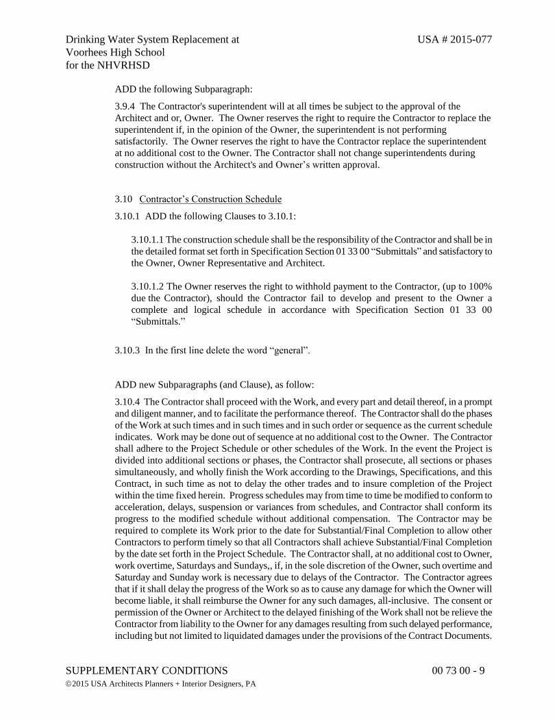
Drinking Water System Replacement at USA # 2015-077
Voorhees High School
for the NHVRHSD
SUPPLEMENTARY CONDITIONS 00 73 00 - 9
2015 USA Architects Planners + Interior Designers, PA
ADD the following Subparagraph:
3.9.4 The Contractor's superintendent will at all times be subject to the approval of the
Architect and or, Owner. The Owner reserves the right to require the Contractor to replace the
superintendent if, in the opinion of the Owner, the superintendent is not performing
satisfactorily. The Owner reserves the right to have the Contractor replace the superintendent
at no additional cost to the Owner. The Contractor shall not change superintendents during
construction without the Architect's and Owner’s written approval.
3.10 Contractor’s Construction Schedule
3.10.1 ADD the following Clauses to 3.10.1:
3.10.1.1 The construction schedule shall be the responsibility of the Contractor and shall be in
the detailed format set forth in Specification Section 01 33 00 “Submittals” and satisfactory to
the Owner, Owner Representative and Architect.
3.10.1.2 The Owner reserves the right to withhold payment to the Contractor, (up to 100%
due the Contractor), should the Contractor fail to develop and present to the Owner a
complete and logical schedule in accordance with Specification Section 01 33 00
“Submittals.”
3.10.3 In the first line delete the word “general”.
ADD new Subparagraphs (and Clause), as follow:
3.10.4 The Contractor shall proceed with the Work, and every part and detail thereof, in a prompt
and diligent manner, and to facilitate the performance thereof. The Contractor shall do the phases
of the Work at such times and in such times and in such order or sequence as the current schedule
indicates. Work may be done out of sequence at no additional cost to the Owner. The Contractor
shall adhere to the Project Schedule or other schedules of the Work. In the event the Project is
divided into additional sections or phases, the Contractor shall prosecute, all sections or phases
simultaneously, and wholly finish the Work according to the Drawings, Specifications, and this
Contract, in such time as not to delay the other trades and to insure completion of the Project
within the time fixed herein. Progress schedules may from time to time be modified to conform to
acceleration, delays, suspension or variances from schedules, and Contractor shall conform its
progress to the modified schedule without additional compensation. The Contractor may be
required to complete its Work prior to the date for Substantial/Final Completion to allow other
Contractors to perform timely so that all Contractors shall achieve Substantial/Final Completion
by the date set forth in the Project Schedule. The Contractor shall, at no additional cost to Owner,
work overtime, Saturdays and Sundays,, if, in the sole discretion of the Owner, such overtime and
Saturday and Sunday work is necessary due to delays of the Contractor. The Contractor agrees
that if it shall delay the progress of the Work so as to cause any damage for which the Owner will
become liable, it shall reimburse the Owner for any such damages, all-inclusive. The consent or
permission of the Owner or Architect to the delayed finishing of the Work shall not be relieve the
Contractor from liability to the Owner for any damages resulting from such delayed performance,
including but not limited to liquidated damages under the provisions of the Contract Documents.
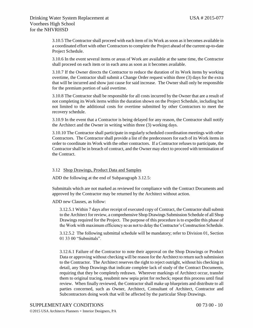
Drinking Water System Replacement at USA # 2015-077
Voorhees High School
for the NHVRHSD
SUPPLEMENTARY CONDITIONS 00 73 00 - 10
2015 USA Architects Planners + Interior Designers, PA
3.10.5 The Contractor shall proceed with each item of its Work as soon as it becomes available in
a coordinated effort with other Contractors to complete the Project ahead of the current up-to-date
Project Schedule.
3.10.6 In the event several items or areas of Work are available at the same time, the Contractor
shall proceed on each item or in each area as soon as it becomes available.
3.10.7 If the Owner directs the Contractor to reduce the duration of its Work items by working
overtime, the Contractor shall submit a Change Order request within three (3) days for the extra
that will be incurred and show just cause for said increase. The Owner shall only be responsible
for the premium portion of said overtime.
3.10.8 The Contractor shall be responsible for all costs incurred by the Owner that are a result of
not completing its Work items within the duration shown on the Project Schedule, including but
not limited to the additional costs for overtime submitted by other Contractors to meet the
recovery schedule.
3.10.9 In the event that a Contractor is being delayed for any reason, the Contractor shall notify
the Architect and the Owner in writing within three (3) working days.
3.10.10 The Contractor shall participate in regularly scheduled coordination meetings with other
Contractors. The Contractor shall provide a list of the predecessors for each of its Work items in
order to coordinate its Work with the other contractors. If a Contractor refuses to participate, the
Contractor shall be in breach of contract, and the Owner may elect to proceed with termination of
the Contract.
3.12 Shop Drawings, Product Data and Samples
ADD the following at the end of Subparagraph 3.12.5:
Submittals which are not marked as reviewed for compliance with the Contract Documents and
approved by the Contractor may be returned by the Architect without action.
ADD new Clauses, as follow:
3.12.5.1 Within 7 days after receipt of executed copy of Contract, the Contractor shall submit
to the Architect for review, a comprehensive Shop Drawings Submission Schedule of all Shop
Drawings required for the Project. The purpose of this procedure is to expedite this phase of
the Work with maximum efficiency so as not to delay the Contractor’s Construction Schedule.
3.12.5.2 The following submittal schedule will be mandatory; refer to Division 01, Section
01 33 00 “Submittals”.
3.12.6.1 Failure of the Contractor to note their approval on the Shop Drawings or Product
Data or approving without checking will be reason for the Architect to return such submission
to the Contractor. The Architect reserves the right to reject outright, without his checking in
detail, any Shop Drawings that indicate complete lack of study of the Contract Documents,
requiring that they be completely redrawn. Wherever markings of Architect occur, transfer
them to original tracing, resubmit new sepia print for recheck; repeat this process until final
review. When finally reviewed, the Contractor shall make up blueprints and distribute to all
parties concerned, such as Owner, Architect, Consultant of Architect, Contractor and
Subcontractors doing work that will be affected by the particular Shop Drawings.
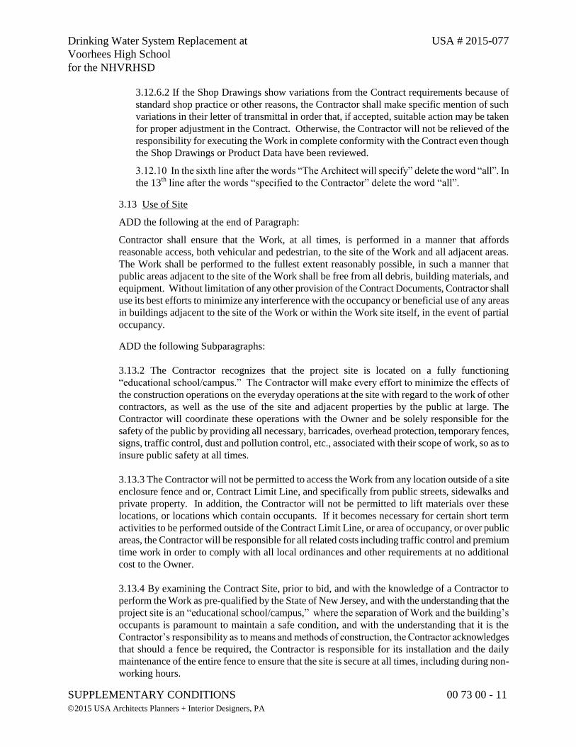
Drinking Water System Replacement at USA # 2015-077
Voorhees High School
for the NHVRHSD
SUPPLEMENTARY CONDITIONS 00 73 00 - 11
2015 USA Architects Planners + Interior Designers, PA
3.12.6.2 If the Shop Drawings show variations from the Contract requirements because of
standard shop practice or other reasons, the Contractor shall make specific mention of such
variations in their letter of transmittal in order that, if accepted, suitable action may be taken
for proper adjustment in the Contract. Otherwise, the Contractor will not be relieved of the
responsibility for executing the Work in complete conformity with the Contract even though
the Shop Drawings or Product Data have been reviewed.
3.12.10 In the sixth line after the words “The Architect will specify” delete the word “all”. In
the 13th line after the words “specified to the Contractor” delete the word “all”.
3.13 Use of Site
ADD the following at the end of Paragraph:
Contractor shall ensure that the Work, at all times, is performed in a manner that affords
reasonable access, both vehicular and pedestrian, to the site of the Work and all adjacent areas.
The Work shall be performed to the fullest extent reasonably possible, in such a manner that
public areas adjacent to the site of the Work shall be free from all debris, building materials, and
equipment. Without limitation of any other provision of the Contract Documents, Contractor shall
use its best efforts to minimize any interference with the occupancy or beneficial use of any areas
in buildings adjacent to the site of the Work or within the Work site itself, in the event of partial
occupancy.
ADD the following Subparagraphs:
3.13.2 The Contractor recognizes that the project site is located on a fully functioning
“educational school/campus.” The Contractor will make every effort to minimize the effects of
the construction operations on the everyday operations at the site with regard to the work of other
contractors, as well as the use of the site and adjacent properties by the public at large. The
Contractor will coordinate these operations with the Owner and be solely responsible for the
safety of the public by providing all necessary, barricades, overhead protection, temporary fences,
signs, traffic control, dust and pollution control, etc., associated with their scope of work, so as to
insure public safety at all times.
3.13.3 The Contractor will not be permitted to access the Work from any location outside of a site
enclosure fence and or, Contract Limit Line, and specifically from public streets, sidewalks and
private property. In addition, the Contractor will not be permitted to lift materials over these
locations, or locations which contain occupants. If it becomes necessary for certain short term
activities to be performed outside of the Contract Limit Line, or area of occupancy, or over public
areas, the Contractor will be responsible for all related costs including traffic control and premium
time work in order to comply with all local ordinances and other requirements at no additional
cost to the Owner.
3.13.4 By examining the Contract Site, prior to bid, and with the knowledge of a Contractor to
perform the Work as pre-qualified by the State of New Jersey, and with the understanding that the
project site is an “educational school/campus,” where the separation of Work and the building’s
occupants is paramount to maintain a safe condition, and with the understanding that it is the
Contractor’s responsibility as to means and methods of construction, the Contractor acknowledges
that should a fence be required, the Contractor is responsible for its installation and the daily
maintenance of the entire fence to ensure that the site is secure at all times, including during non-
working hours.
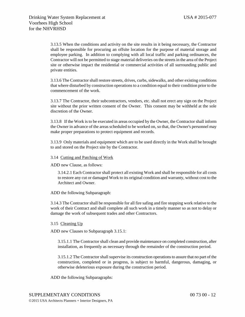
Drinking Water System Replacement at USA # 2015-077
Voorhees High School
for the NHVRHSD
SUPPLEMENTARY CONDITIONS 00 73 00 - 12
2015 USA Architects Planners + Interior Designers, PA
3.13.5 When the conditions and activity on the site results in it being necessary, the Contractor
shall be responsible for procuring an offsite location for the purpose of material storage and
employee parking. In addition to complying with all local traffic and parking ordinances, the
Contractor will not be permitted to stage material deliveries on the streets in the area of the Project
site or otherwise impact the residential or commercial activities of all surrounding public and
private entities.
3.13.6 The Contractor shall restore streets, drives, curbs, sidewalks, and other existing conditions
that where disturbed by construction operations to a condition equal to their condition prior to the
commencement of the work.
3.13.7 The Contractor, their subcontractors, vendors, etc. shall not erect any sign on the Project
site without the prior written consent of the Owner. This consent may be withheld at the sole
discretion of the Owner.
3.13.8 If the Work is to be executed in areas occupied by the Owner, the Contractor shall inform
the Owner in advance of the areas scheduled to be worked on, so that, the Owner's personnel may
make proper preparations to protect equipment and records.
3.13.9 Only materials and equipment which are to be used directly in the Work shall be brought
to and stored on the Project site by the Contractor.
3.14 Cutting and Patching of Work
ADD new Clause, as follows:
3.14.2.1 Each Contractor shall protect all existing Work and shall be responsible for all costs
to restore any cut or damaged Work to its original condition and warranty, without cost to the
Architect and Owner.
ADD the following Subparagraph:
3.14.3 The Contractor shall be responsible for all fire safing and fire stopping work relative to the
work of their Contract and shall complete all such work in a timely manner so as not to delay or
damage the work of subsequent trades and other Contractors.
3.15 Cleaning Up
ADD new Clauses to Subparagraph 3.15.1:
3.15.1.1 The Contractor shall clean and provide maintenance on completed construction, after
installation, as frequently as necessary through the remainder of the construction period.
3.15.1.2 The Contractor shall supervise its construction operations to assure that no part of the
construction, completed or in progress, is subject to harmful, dangerous, damaging, or
otherwise deleterious exposure during the construction period.
ADD the following Subparagraphs:
Drinking Water System Replacement at USA # 2015-077
Voorhees High School
for the NHVRHSD
SUPPLEMENTARY CONDITIONS 00 73 00 - 13
2015 USA Architects Planners + Interior Designers, PA
3.15.3 The Contractor shall, on a daily basis, clean debris resulting from the Work and protect all
construction in progress, and provide protective covering where required to assure protection from
damage or deterioration until Substantial Completion.
3.15.4 The Contractor shall remove all surplus material, false work, temporary structures,
including foundations thereof, plant of any description, and debris of every nature resulting from
his operations and to put the site in a neat orderly condition prior to Substantial Completion.
3.15.5 The Contractor shall restore all areas which have been used for storage of materials and
equipment, and all areas which have been disturbed by his operations to their original conditions,
or to a condition satisfactory to and approved by the Owner, including but not limited to all site
pavement and or, grassed areas.
1.4 MODIFICATIONS TO ARTICLE 4 – ARCHITECT
4.1 General
ADD the following to the beginning of paragraph 4.1.1:
The term "Architect" is referenced in Section 00 21 13 “Instructions to Bidders”.
ADD the following at the end of Subparagraph 4.1.1:
The term “Architect” means the Architect or the Architect’s authorized representative.
4.2 Administration of the Contract
ADD new Clause to Subparagraphs to 4.2.1:
4.2.1.1 Payment for the Architect’s Construction Phase Services will be by Owner and begin
upon the Award of the Contract and will terminate two weeks after the Contract date for
Substantial Completion of the Work, unless extended by the Owner/Architect Agreement. To
the extent the Architect’s services are required beyond sixty days, the Architect shall be
compensated by the Contractor by credit change order.
ADD new Clause to Subparagraphs to 4.2.7:
4.2.7.1 The Architect reserves the right to extend the time for review and responses to shop
drawings, product data and samples if the submittal is not on the Contractor’s Critical Path,
per the Contractor’s approved Construction schedule, or if the Contractor is late (beyond the
specified date required for shop drawing delivery to the Architect), in providing shop
drawings based on the Construction Schedule, or lack thereof. Failure to properly inform the
Architect or otherwise give such written notice shall waive the contractor’s right to seek a
delay, request additional time or cost under the Changes Article of these General Conditions.
DELETE the last sentence of Subparagraph 4.2.11 and insert the following:
Drinking Water System Replacement at USA # 2015-077
Voorhees High School
for the NHVRHSD
SUPPLEMENTARY CONDITIONS 00 73 00 - 14
2015 USA Architects Planners + Interior Designers, PA
If no agreement is made concerning the time within which interpretations required of the Architect
shall be furnished in compliance with section 4.2, then delay shall not be recognized on account
of failure by the Architect to furnish such interpretation until 15 days after written request is made
and 15 days after decision is required based on the Critical Path of the item as shown on the
approved Contractor’s Construction Schedule.
DELETE 4.2.14 and REPLACE with the following:
4.2.14 Requests For Information
4.2.14.1 In the event the contractor or his subcontractor determines that some portion of
the drawings, specifications, or other contract documents requires clarification or
interpretation by the Owner, the contractor shall submit a Request For Information in
writing to the Architect. Requests for information may only be submitted by the
Contractor and shall only be submitted on the Request For Information form provided
by the Architect. The Contractor shall clearly and concisely set forth the issue for which
the clarification or interpretation is sought and why a response is needed from the
Owner. In the request For Information, the contractor shall set forth an interpretation or
understanding of the requirement along with reasons why such an understanding was
reached.
4.2.14.2 The Owner and Architect acknowledge that this is a complex project. Based
upon the Architect’s past experience with projects of similar complexity the Owner
anticipates that there will probably be numerous Requests For Information on this
project.
4.2.14.3 The Architect will review all Requests for Information to determine whether
they are Requests for Information with the meaning of this term. If the Architect
determines that the document is not a Request for Information, it will be returned to the
Contractor, unreviewed as to content, for resubmittal on the proper form and in the
proper manner.
4.2.14.4 Responses from the Architect will not change any requirement in the Contract
Documents. In the event the Contractor believes that a response to a Request For
Information will cause a change to the requirements of the Contract Document, the
Contractor shall immediately give written notice to the Owner stating that the Contractor
considers the response to be a Change Order. Failure to give such written notice
immediately shall waive the contractors right to seek additional time or cost under the
Changes article of these General Conditions.
1.5 MODIFICATIONS TO ARTICLE 5 – SUBCONTRACTORS
5.2 Award of Subcontracts and Other Contracts for Portion of the Work
DELETE Subparagraph 5.2.1 in its entirety and REPLACE with the following:
5.2.1 Within 7 days after Notice to Proceed, the Contractor shall furnish to the Architect in
writing, for review by the Owner and the Architect, a list of the names of all Subcontractors, Sub-
Drinking Water System Replacement at USA # 2015-077
Voorhees High School
for the NHVRHSD
SUPPLEMENTARY CONDITIONS 00 73 00 - 15
2015 USA Architects Planners + Interior Designers, PA
subcontractors, fabricators, manufacturers, sources of supply, articles, devices, fixtures, pieces of
equipment, materials and processes proposed for each item of Work on List of Subcontractors,
AIA Document G805. The Architect will promptly notify the Contractor, in writing, if either the
Owner or the Architect, after due investigation, has reasonable objection to any names on such
list. Failure of the Owner and Architect to make objection promptly to any name on the list shall
constitute acceptance of such name.
5.2.1.1 In submitting the names of subcontractors, the Contractor shall list 1) the extent of
limitations of the trades or work included by specifications paragraph number, 2) the name
and address of the Subcontractor, 3) the name and address of all Sub-subcontractors for each
significant subdivision of the trade or work, and if required by the Architect, 4) reference in
the form of a list of at least 3 jobs similar in size and quality to this Project performed in the
last 5 years, with name, location of work, dollar value and names of the Owner and Architect.
DELETE Subparagraph 5.2.3 in its entirety and REPLACE with the following:
5.2.3 If the Owner, or Architect has objection to a person or entity proposed by the Contractor,
the contractor shall propose another whom the Owner, Architect, has no objection to. The
Contract Sum shall not be increased by any difference due to any costs associated by such change.
ADD new Subparagraph, as follows:
5.2.5 The Contractor shall provide at the Project site, and in its shops and those of its suppliers
and Subcontractors, an opportunity for the Owner, the Architect and/or Engineer, at any time and
from time to time, to inspect the quality and quantity of materials and work in process, and shall
insure that such facilities are safe for such inspections.
1.6 MODIFICATIONS TO ARTICLE 6 – CONSTRUCTION BY OWNER OR BY
SEPARATE CONTRACTORS
6.1 Owner’s Right to Perform Construction and to Award Separate Contracts
6.1.1 MODIFY the Subparagraph as follows:
ADD a period after the words; “Conditions of the Contract. DELETE the remaining paragraph.
6.2 Mutual Responsibility
ADD new Subparagraphs, as follow:
6.2.6 Each Contractor shall cooperate with all other Contractors in forwarding the interest of the
Owner, and shall coordinate with their Work that of all other Contractors under the direction of
the General Contractor, who shall be in charge of the progress of the Project and all divisions and
subdivisions thereof.
6.2.7 Any conflict in or between the Drawings and Specifications as to which of the separate
Contractors are to perform specific Work shall be resolved by the Architect, whose decisions shall
be final and binding.
Drinking Water System Replacement at USA # 2015-077
Voorhees High School
for the NHVRHSD
SUPPLEMENTARY CONDITIONS 00 73 00 - 16
2015 USA Architects Planners + Interior Designers, PA
6.3 Owner’s Right to Clean Up
ADD new Clause to Subparagraph 6.3.1:
6.3.1.1 Costs to be deducted from each contractor through Change Order, or Construction
Change Directive.
1.7 MODIFICATIONS TO ARTICLE 7 – CHANGES IN THE WORK
7.1 General
ADD new Subparagraph, as follows:
7.1.4 Where Work is required to be done and the parties cannot agree as to whether such Work is
extra Work or as to valuation by reason of any modification as herein provided, then the
performance of such Work shall not be delayed, and the Contractor shall immediately proceed
with the Work upon the written order of the Owner or designated representative. The failure of
the Contractor to proceed as herein provided shall constitute a material breach of this Contract,
regardless of whether or not the Contractor is correct in its contentions, it being understood that
the progress of the Work may not be delayed by any controversy between the Owner and the
Contractor.
7.2 Change Orders
ADD new Subparagraph, as follows:
7.2.2 Methods used in determining adjustments to the Contract sum are as noted in 7.3.1.
ADD new Subparagraph, as follows:
7.2.3 Agreement on any Change Order shall constitute a final settlement of all matters relating to
the change in the Work that is the subject of the Change Order, including but not limited to all
direct and indirect costs associated with such change, any impact such change may have on the
unchanged Work, and any and all adjustments to the Contract Sum and the Project Construction
Schedule. In the event a Change Order increases the Contact Sum, the Contractor shall include
the Work covered by such Change Orders in Applications for Payment as if such Work were
originally part of the Contract Documents.
7.3 Construction Change Directives
DELETE the first sentence in Subparagraph 7.3.7 and REPLACE with the following:
If the Contractor does not respond promptly or disagrees with the method for adjustment in the
Contract Sum, the Architect shall determine the method and the adjustment on the basis of
reasonable expenditures and savings of those performing the Work attributable to the change,
including, in case of an increase in the Contract Sum, an allowance for overhead and profit in
accordance with the schedule set forth in Subparagraph 7.3.11 below.
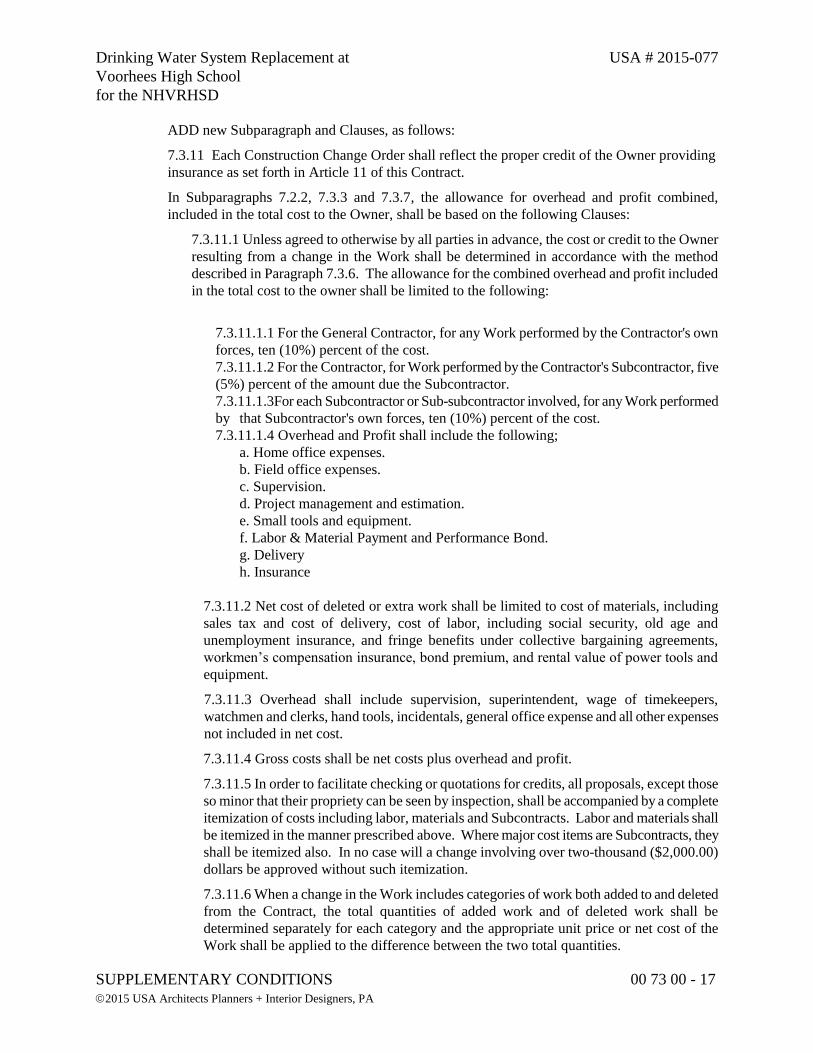
Drinking Water System Replacement at USA # 2015-077
Voorhees High School
for the NHVRHSD
SUPPLEMENTARY CONDITIONS 00 73 00 - 17
2015 USA Architects Planners + Interior Designers, PA
ADD new Subparagraph and Clauses, as follows:
7.3.11 Each Construction Change Order shall reflect the proper credit of the Owner providing
insurance as set forth in Article 11 of this Contract.
In Subparagraphs 7.2.2, 7.3.3 and 7.3.7, the allowance for overhead and profit combined,
included in the total cost to the Owner, shall be based on the following Clauses:
7.3.11.1 Unless agreed to otherwise by all parties in advance, the cost or credit to the Owner
resulting from a change in the Work shall be determined in accordance with the method
described in Paragraph 7.3.6. The allowance for the combined overhead and profit included
in the total cost to the owner shall be limited to the following:
7.3.11.1.1 For the General Contractor, for any Work performed by the Contractor's own
forces, ten (10%) percent of the cost.
7.3.11.1.2 For the Contractor, for Work performed by the Contractor's Subcontractor, five
(5%) percent of the amount due the Subcontractor.
7.3.11.1.3For each Subcontractor or Sub-subcontractor involved, for any Work performed
by that Subcontractor's own forces, ten (10%) percent of the cost.
7.3.11.1.4 Overhead and Profit shall include the following;
a. Home office expenses.
b. Field office expenses.
c. Supervision.
d. Project management and estimation.
e. Small tools and equipment.
f. Labor & Material Payment and Performance Bond.
g. Delivery
h. Insurance
7.3.11.2 Net cost of deleted or extra work shall be limited to cost of materials, including
sales tax and cost of delivery, cost of labor, including social security, old age and
unemployment insurance, and fringe benefits under collective bargaining agreements,
workmen’s compensation insurance, bond premium, and rental value of power tools and
equipment.
7.3.11.3 Overhead shall include supervision, superintendent, wage of timekeepers,
watchmen and clerks, hand tools, incidentals, general office expense and all other expenses
not included in net cost.
7.3.11.4 Gross costs shall be net costs plus overhead and profit.
7.3.11.5 In order to facilitate checking or quotations for credits, all proposals, except those
so minor that their propriety can be seen by inspection, shall be accompanied by a complete
itemization of costs including labor, materials and Subcontracts. Labor and materials shall
be itemized in the manner prescribed above. Where major cost items are Subcontracts, they
shall be itemized also. In no case will a change involving over two-thousand ($2,000.00)
dollars be approved without such itemization.
7.3.11.6 When a change in the Work includes categories of work both added to and deleted
from the Contract, the total quantities of added work and of deleted work shall be
determined separately for each category and the appropriate unit price or net cost of the
Work shall be applied to the difference between the two total quantities.
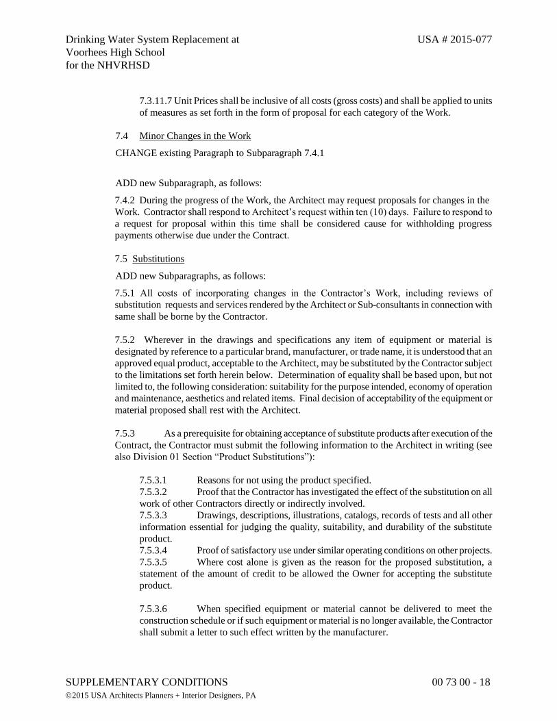
Drinking Water System Replacement at USA # 2015-077
Voorhees High School
for the NHVRHSD
SUPPLEMENTARY CONDITIONS 00 73 00 - 18
2015 USA Architects Planners + Interior Designers, PA
7.3.11.7 Unit Prices shall be inclusive of all costs (gross costs) and shall be applied to units
of measures as set forth in the form of proposal for each category of the Work.
7.4 Minor Changes in the Work
CHANGE existing Paragraph to Subparagraph 7.4.1
ADD new Subparagraph, as follows:
7.4.2 During the progress of the Work, the Architect may request proposals for changes in the
Work. Contractor shall respond to Architect’s request within ten (10) days. Failure to respond to
a request for proposal within this time shall be considered cause for withholding progress
payments otherwise due under the Contract.
7.5 Substitutions
ADD new Subparagraphs, as follows:
7.5.1 All costs of incorporating changes in the Contractor’s Work, including reviews of
substitution requests and services rendered by the Architect or Sub-consultants in connection with
same shall be borne by the Contractor.
7.5.2 Wherever in the drawings and specifications any item of equipment or material is
designated by reference to a particular brand, manufacturer, or trade name, it is understood that an
approved equal product, acceptable to the Architect, may be substituted by the Contractor subject
to the limitations set forth herein below. Determination of equality shall be based upon, but not
limited to, the following consideration: suitability for the purpose intended, economy of operation
and maintenance, aesthetics and related items. Final decision of acceptability of the equipment or
material proposed shall rest with the Architect.
7.5.3 As a prerequisite for obtaining acceptance of substitute products after execution of the
Contract, the Contractor must submit the following information to the Architect in writing (see
also Division 01 Section “Product Substitutions”):
7.5.3.1 Reasons for not using the product specified.
7.5.3.2 Proof that the Contractor has investigated the effect of the substitution on all
work of other Contractors directly or indirectly involved.
7.5.3.3 Drawings, descriptions, illustrations, catalogs, records of tests and all other
information essential for judging the quality, suitability, and durability of the substitute
product.
7.5.3.4 Proof of satisfactory use under similar operating conditions on other projects.
7.5.3.5 Where cost alone is given as the reason for the proposed substitution, a
statement of the amount of credit to be allowed the Owner for accepting the substitute
product.
7.5.3.6 When specified equipment or material cannot be delivered to meet the
construction schedule or if such equipment or material is no longer available, the Contractor
shall submit a letter to such effect written by the manufacturer.
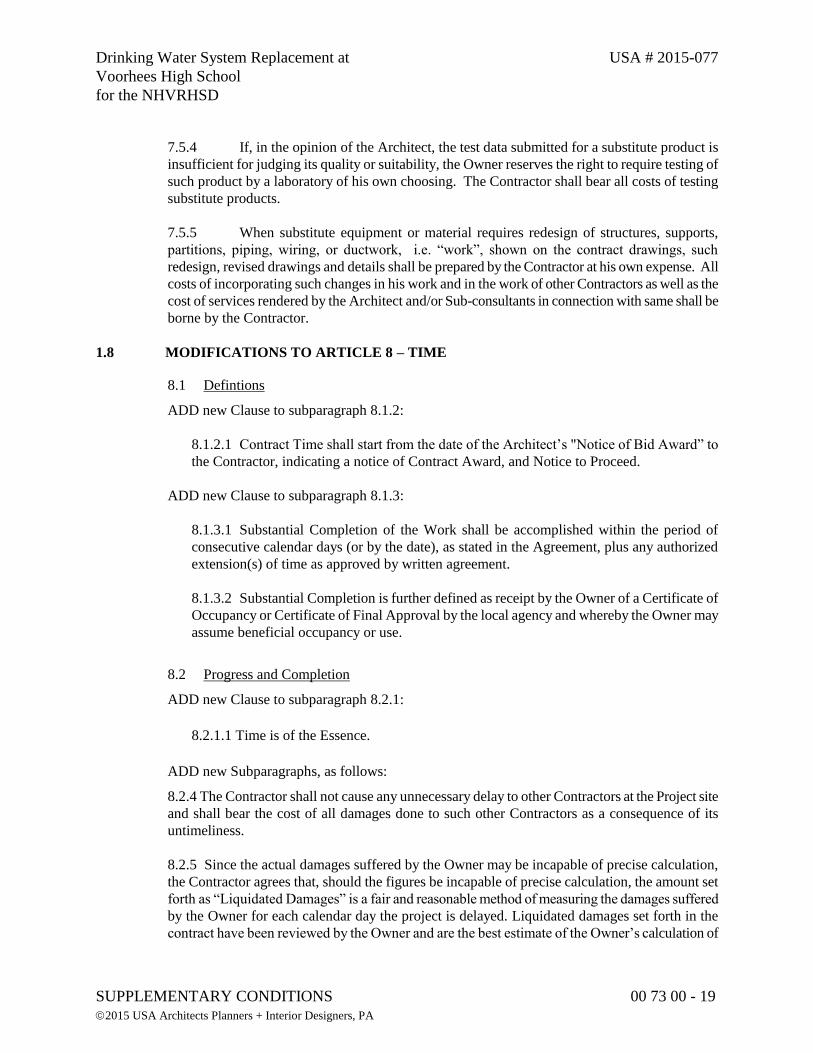
Drinking Water System Replacement at USA # 2015-077
Voorhees High School
for the NHVRHSD
SUPPLEMENTARY CONDITIONS 00 73 00 - 19
2015 USA Architects Planners + Interior Designers, PA
7.5.4 If, in the opinion of the Architect, the test data submitted for a substitute product is
insufficient for judging its quality or suitability, the Owner reserves the right to require testing of
such product by a laboratory of his own choosing. The Contractor shall bear all costs of testing
substitute products.
7.5.5 When substitute equipment or material requires redesign of structures, supports,
partitions, piping, wiring, or ductwork, i.e. “work”, shown on the contract drawings, such
redesign, revised drawings and details shall be prepared by the Contractor at his own expense. All
costs of incorporating such changes in his work and in the work of other Contractors as well as the
cost of services rendered by the Architect and/or Sub-consultants in connection with same shall be
borne by the Contractor.
1.8 MODIFICATIONS TO ARTICLE 8 – TIME
8.1 Defintions
ADD new Clause to subparagraph 8.1.2:
8.1.2.1 Contract Time shall start from the date of the Architect’s "Notice of Bid Award” to
the Contractor, indicating a notice of Contract Award, and Notice to Proceed.
ADD new Clause to subparagraph 8.1.3:
8.1.3.1 Substantial Completion of the Work shall be accomplished within the period of
consecutive calendar days (or by the date), as stated in the Agreement, plus any authorized
extension(s) of time as approved by written agreement.
8.1.3.2 Substantial Completion is further defined as receipt by the Owner of a Certificate of
Occupancy or Certificate of Final Approval by the local agency and whereby the Owner may
assume beneficial occupancy or use.
8.2 Progress and Completion
ADD new Clause to subparagraph 8.2.1:
8.2.1.1 Time is of the Essence.
ADD new Subparagraphs, as follows:
8.2.4 The Contractor shall not cause any unnecessary delay to other Contractors at the Project site
and shall bear the cost of all damages done to such other Contractors as a consequence of its
untimeliness.
8.2.5 Since the actual damages suffered by the Owner may be incapable of precise calculation,
the Contractor agrees that, should the figures be incapable of precise calculation, the amount set
forth as “Liquidated Damages” is a fair and reasonable method of measuring the damages suffered
by the Owner for each calendar day the project is delayed. Liquidated damages set forth in the
contract have been reviewed by the Owner and are the best estimate of the Owner’s calculation of
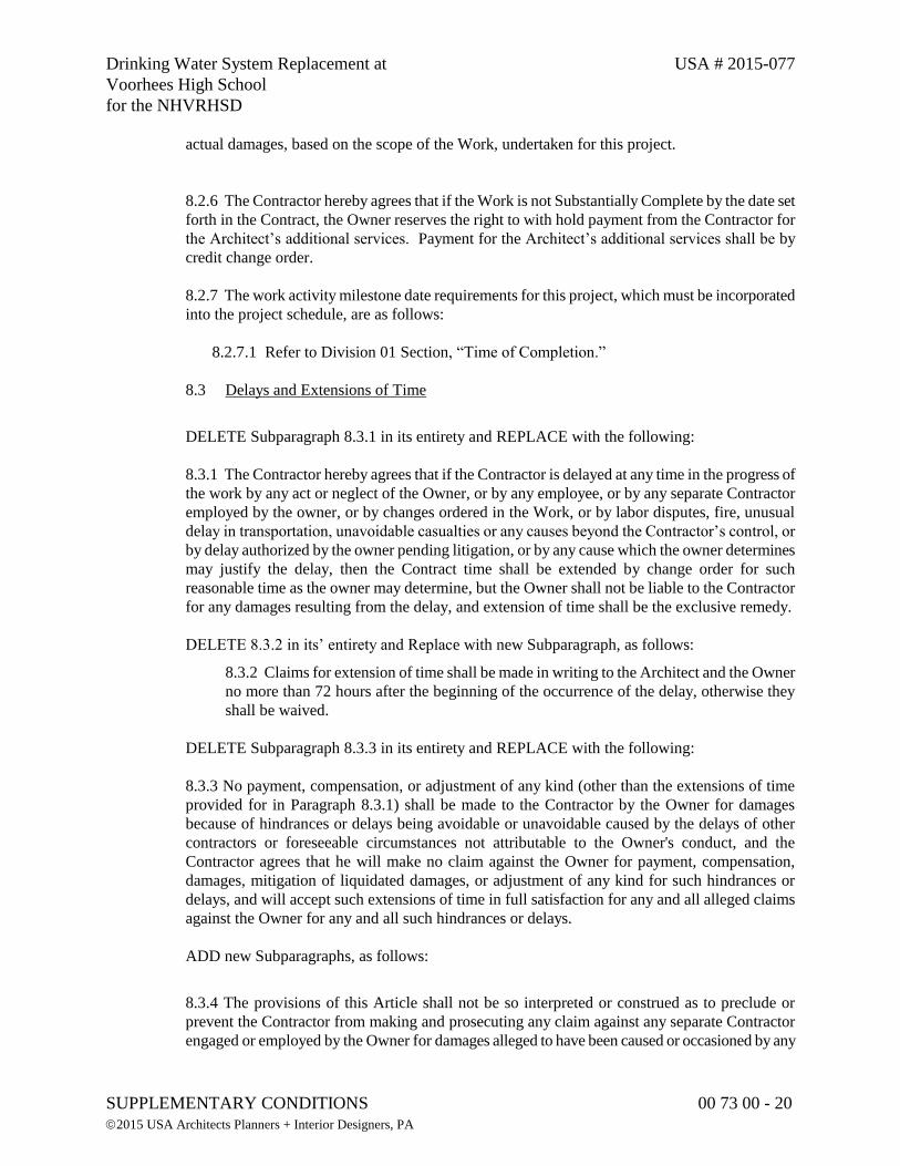
Drinking Water System Replacement at USA # 2015-077
Voorhees High School
for the NHVRHSD
SUPPLEMENTARY CONDITIONS 00 73 00 - 20
2015 USA Architects Planners + Interior Designers, PA
actual damages, based on the scope of the Work, undertaken for this project.
8.2.6 The Contractor hereby agrees that if the Work is not Substantially Complete by the date set
forth in the Contract, the Owner reserves the right to with hold payment from the Contractor for
the Architect’s additional services. Payment for the Architect’s additional services shall be by
credit change order.
8.2.7 The work activity milestone date requirements for this project, which must be incorporated
into the project schedule, are as follows:
8.2.7.1 Refer to Division 01 Section, “Time of Completion.”
8.3 Delays and Extensions of Time
DELETE Subparagraph 8.3.1 in its entirety and REPLACE with the following:
8.3.1 The Contractor hereby agrees that if the Contractor is delayed at any time in the progress of
the work by any act or neglect of the Owner, or by any employee, or by any separate Contractor
employed by the owner, or by changes ordered in the Work, or by labor disputes, fire, unusual
delay in transportation, unavoidable casualties or any causes beyond the Contractor’s control, or
by delay authorized by the owner pending litigation, or by any cause which the owner determines
may justify the delay, then the Contract time shall be extended by change order for such
reasonable time as the owner may determine, but the Owner shall not be liable to the Contractor
for any damages resulting from the delay, and extension of time shall be the exclusive remedy.
DELETE 8.3.2 in its’ entirety and Replace with new Subparagraph, as follows:
8.3.2 Claims for extension of time shall be made in writing to the Architect and the Owner
no more than 72 hours after the beginning of the occurrence of the delay, otherwise they
shall be waived.
DELETE Subparagraph 8.3.3 in its entirety and REPLACE with the following:
8.3.3 No payment, compensation, or adjustment of any kind (other than the extensions of time
provided for in Paragraph 8.3.1) shall be made to the Contractor by the Owner for damages
because of hindrances or delays being avoidable or unavoidable caused by the delays of other
contractors or foreseeable circumstances not attributable to the Owner's conduct, and the
Contractor agrees that he will make no claim against the Owner for payment, compensation,
damages, mitigation of liquidated damages, or adjustment of any kind for such hindrances or
delays, and will accept such extensions of time in full satisfaction for any and all alleged claims
against the Owner for any and all such hindrances or delays.
ADD new Subparagraphs, as follows:
8.3.4 The provisions of this Article shall not be so interpreted or construed as to preclude or
prevent the Contractor from making and prosecuting any claim against any separate Contractor
engaged or employed by the Owner for damages alleged to have been caused or occasioned by any
Drinking Water System Replacement at USA # 2015-077
Voorhees High School
for the NHVRHSD
SUPPLEMENTARY CONDITIONS 00 73 00 - 21
2015 USA Architects Planners + Interior Designers, PA
such separate Contractor.
8.3.5 An extension of time shall be allowed equal to the total period of any delay caused by
injunction or other legal proceedings, insofar as such proceedings prevent the Contractor from
proceeding with the work, but no extension shall be allowed unless such legal proceedings shall
be diligently prosecuted by the Contractor and, provided further that, in no case shall such delay
be deemed to begin until the Contractor shall have given written notice to the Owner of the
injunction or other action of delay and shall have delivered to the Owner a copy of the injunction
or other orders and the papers upon which the time shall have been granted.
8.3.6 The Owner may suspend the whole or any part of the work, if it shall deem it for the best
interest of the Owner to do so, without compensation to the Contractor for such suspension other
than extending the time for completion of the work as much as it may have been delayed by such
suspension. During such suspension, all materials delivered upon but not placed in the work, shall
be neatly piled by the Contractor so as not to obstruct public travel or shall be removed from the
line of work at the direction of the Owner and, unless the materials be moved by the Contractor
upon such direction, the materials shall be removed by the Owner and expense thereof will be
charged to the Contractor.
ADD new Paragraph and Subparagraphs, as follows:
8.4 Completion And Liquidated Damages
8.4.1 The Contractor shall substantially complete all of his Work included in the Contract
Documents ready for the Owner's occupancy as defined in the General Conditions, in accordance
with the allotted time indicated in Division 01, Section “Time of Completion”, and on the
Contractor's Form of Proposal, subject to extensions of contract time as provided in the General
Conditions.
8.4.2 The Contractor shall fully complete all of his Work included in the Contract Documents as
defined in the General Conditions, in accordance with the allotted time indicated in Division 01,
Section “Time of Completion”, and on the Contractor's Form of Proposal, of notice to proceed,
subject to extensions of contract time as provided in the General Conditions.
8.4.3 Should the Contractor fail to complete fully and in conformity with all provisions of the
Contract within the Contract Time and the milestones set forth in The Contract, the Contractor
shall and hereby agrees to pay the Owner the sum indicated on the Contract for each consecutive
calendar day beyond the number of days allowed by the Contract, which sum is agreed upon as
reasonable and proper measure of damages which the Owner will sustain per diem by failure of
Contractor to complete work within time as stipulated; it being recognized by Owner and
Contractor that the injury to Owner which could result from a failure of the Contractor to complete
on schedule is uncertain and cannot be computed exactly. In no way shall costs of Liquidated
Damages be construed as a penalty.
8.4.4 It is hereby understood and mutually agreed, by and between the Contractor and the Owner,
that the date of beginning and the time for completion as specified in the Contract of the work to
be done there under are essential conditions of this Contract; and it is further mutually understood
and agreed that the work embraced in this Contract shall be commenced on or before a date to be
specified in the Owner's written notice to commence the work.
Drinking Water System Replacement at USA # 2015-077
Voorhees High School
for the NHVRHSD
SUPPLEMENTARY CONDITIONS 00 73 00 - 22
2015 USA Architects Planners + Interior Designers, PA
8.4.5 The Contractor agrees that said work shall be prosecuted regularly, diligently, and
uninterruptedly at such rate of progress as will insure full completion thereof within the time
specified. It is expressly understood and agreed, by and between the Contractor and the Owner,
that the time for the completion of all work described in the Contract Documents is a reasonable
time for the completion of same, taking into consideration the average climatic range and usual
industrial conditions prevailing in this locality.
8.4.6 If the said Contractor shall neglect, fail, or refuse to complete the work within the time
specified in the Contract, or within such further time as may be properly granted by the Owner in
accordance with the provisions of this Contract, then the Contractor does hereby agree, as a part
consideration for the awarding of this Contract, to pay to the Owner the amount specified in the
Contract, not as a penalty but as liquidated damages for such breach of Contract as hereinafter set
forth, for each and every calendar day that the Contractor shall exceed the time stipulated in the
Contract for completing the work.
8.4.7 The said amount is fixed and agreed upon by and between the Contractor and the Owner
because of the impracticability and extreme difficulty of fixing and ascertaining the true value of
the damages which the Owner will sustain by failure of the Contractor to complete the work on
time, such as loss of revenue from service charges, additional costs of interest charges, delays
caused to other work by failure to perform this Contract, and other damages, some of which are
indefinite and not susceptible of easy proof, and said amount is agreed to be the amount of
damage which the Owner will sustain and said amount shall be recovered by the Owner by
deducting the same out of any monies due or that may become due the Contractor, and if said
monies are insufficient to cover said damages, then the Contractor or his Surety shall pay the
amount of the difference.
8.4.8 The costs of engineering and inspection performed during overtime hours, or after the
specified date of completion (regardless of the granting of extensions of time), shall be deducted
from funds owed to the Contractor, as damages sustained by the Owner caused solely by actions
of the Contractor.
8.4.9 It is further agreed that time is of the essence of each and every portion of this Contract and
of the specifications, wherein a definite and certain length of time is fixed for the performance of
any act whatsoever; and where under the Contract an extension of time is allowed for the
completion of any work, the new time limit fixed by such extension shall be of the essence of this
Contract.
8.4.10 It is also agreed that the Contractor will not be charged with liquidated damages when the
Owner determines that the Contractor is without fault and that the Contractor's reasons for
requesting a time extension are acceptable to the Owner. If an extension of time is approved, said
liquidated damages will be charged the Contractor from the end of such extension to the
completion of the work. However, whether or not an extension of time is granted by the Owner,
the Contractor shall pay to the Owner all costs of engineering field work and inspection from the
completion date, as determined from the number of days specified for completing the work, to the
date of actual completion.
Drinking Water System Replacement at USA # 2015-077
Voorhees High School
for the NHVRHSD
SUPPLEMENTARY CONDITIONS 00 73 00 - 23
2015 USA Architects Planners + Interior Designers, PA
1.9 MODIFICATIONS TO ARTICLE 9 – PAYMENTS AND COMPLETION
9.3 Applications for Payment
ADD new Clauses, as follows:
9.3.1.3 To ensure satisfactory completion of the Work under the Contract Documents, the
Owner shall withhold a retainage from each progress payment. In the event there is a
specific cause for greater withholding, retainage may be assessed on the balance of the
Work, or may be increased as necessary to protect the Owner’s interest as the Owner shall
determine in its sole discretion. In the event a dispute arises between the Owner and the
Contractor, which dispute is based upon increased costs claimed by the Contractor
occasioned by delays or other actions of another Prime Contractor, additional retainage in
the sum of one and one-half times the amount of any possible liability may be withheld until
such time as a final resolution is agreed to by all parties directly or indirectly involved,
unless the Contractor causing the additional claim furnishes a bond satisfactory to the
Owner to indemnify such Owner against the claim. However, all such monies retained by
the Owner may be withheld from the Contractor until Substantial Completion of the
Contract.
(a) Refer to Division 01 Section "Applications for Payment" for withholding amounts as
well as additional directives.
9.3.2.1 Payments for stored materials and equipment, whether stored on or off the site, are
not the obligation of the Owner. Payments for such stored material and equipment may be
made electively and purely upon the discretion of the Owner, and on the advice of the
Architect.
ADD new Subparagraph, as follows:
9.3.4 Each Application for Payment shall be accompanied by the following, all in form and
substance satisfactory to the Owner: (i) a current Contractor’s lien waiver and duly executed and
acknowledged sworn statement showing all Subcontractors and material suppliers with whom the
Contractor has entered into subcontracts, the amount of each such subcontract, the amount
requested for any Subcontractor and material supplier in the requested progress payment, and the
amount to be paid to the Contractor from such progress payment, together with similar sworn
statements from all such Subcontractors and material suppliers; (ii) duly executed waivers of
mechanics’ and material suppliers’ liens from all Subcontractors and, when appropriate, from
material suppliers and lower tier Subcontractors establishing payment or satisfaction of payment
of all amounts requested by the Contractor on behalf of such entities or persons in any previous
Application for Payment; and (iii) all information and materials required to comply with the
requirements of the Contract Documents or reasonably requested by the Owner or the Architect.
9.5 Decisions to Withhold Certification
ADD new Clauses to Subparagraph 9.5.1:
9.5.1.8 Avoidable delay in the progress of the Work.
Drinking Water System Replacement at USA # 2015-077
Voorhees High School
for the NHVRHSD
SUPPLEMENTARY CONDITIONS 00 73 00 - 24
2015 USA Architects Planners + Interior Designers, PA
9.5.1.9 Deliberate delay in the submission for approval of names of subcontractors,
materialmen, sources of supply, shop drawings and samples.
9.5.1.10 Failure of the Contractor to maintain scheduled progress or meet intermediate
milestones.
9.5.1.11 Failure to submit certified payroll records covering previous payment periods, or
otherwise fail to comply with the New Jersey Prevailing Wage Act.
9.5.1.12 Where Work performed has not been performed in the manner required under the
Contract Documents and the Construction Manager or Architect require additional time to
determine if the Work will perform as required by the Contract Documents.
9.5.1.13 Failure to submit waivers of Claims from all subcontractors as well as relevant
entities for the previous period.
9.5.1.14 Failure of the Contractor to submit revised schedule updates.
ADD new Subparagraph, as follows:
9.5.4 In the event of a decision to withhold any portion of a payment application, notice of that
determination shall be issued to the Contractor and to the Surety, and the Contractor shall cause its
Surety to attend any and all reasonably required meetings with the Owner, Architect or
Construction Manager and to issue a specific Consent of Surety as a pre-condition to any
subsequent release of the payment application or portions thereof that have been withheld.
9.6 Progress Payments
9.6.2 REVISE Subparagraph to read as follows: The Contractor shall pay each Subcontractor
within 20 days of the receipt of payment from the Owner, an amount equal to the percentage of
completion allowed to the Contractor on account of such Subcontractor’s work, less the
percentage retained from payments to the Contractor. The Contractor shall also require each
Subcontractor to make similar payments to his Subcontractors.
ADD new Clauses, as follow:
9.6.2.1 If the Architect fails to approve an Application for Payment for any cause which is
the fault of the Contractor and not the fault of a particular Subcontractor, the Contractor
shall pay that Subcontractor on demand, made at any time after Application for Payment
should otherwise have been approved, for their Work to extent completed, less the retained
percentage.
9.7 Failure of Payment:
9.7.1 Delete the first; “seven,” from the first sentence and insert the word, “fourteen.” Delete the
second, “seven,” from the first sentence and insert the word, “thirty.” Delete the third, “seven,”
from the first sentence and insert the word, “twenty-one.”
ADD new Subparagraph, as follows:
Drinking Water System Replacement at USA # 2015-077
Voorhees High School
for the NHVRHSD
SUPPLEMENTARY CONDITIONS 00 73 00 - 25
2015 USA Architects Planners + Interior Designers, PA
9.7.2 If the Owner is entitled to any reimbursement or payment from the Contractor under or
pursuant to the Contract Documents, such payment shall be made promptly upon demand by the
Owner. Notwithstanding anything contained in the Contract Documents to the contrary, if the
Contractor fails to promptly make any payment due the Owner, or the Owner incurs any costs and
expenses to cure any default of the Contractor or to correct defective Work, the Owner shall have
an absolute right to offset such amount against the Contract Sum and may, in the Owner=s sole
discretion, elect either to: (1) deduct an amount equal to that which the Owner is entitled from any
payment then or thereafter due the Contractor from the Owner, or (2) issue a written notice to the
Contractor reducing the Contract Sum by an amount equal to that which the Owner is entitled.
9.8 Substantial Completion:
ADD the following to the end of Subparagraph 9.8.1:
provided, however, that a condition precedent to Substantial Completion shall be the Owner’s
receipt of all certificates of occupancy and any other permits, approvals, licenses, and other
documents from any governmental authority having jurisdiction thereof necessary for the
occupancy of the project.
9.9 Partial Occupancy or Use:
ADD new Subparagraphs, as follow:
9.9.4 When prior occupancy or use of completed portions is requested by the Owner, the
Architect will make a prior occupancy inspection to establish the conditions of the Work at time of
occupancy. Use of occupancy by the Owner prior to final acceptance does not relieve the
Contractor of their responsibility to maintain all insurance and bonds required of the Contractor
during the life of the Contract. The Contractor shall not be held responsible for any damage to the
occupied part of the Project resulting from the Owner’s occupancy. Occupancy by the Owner
shall not be deemed to constitute a waiver of existing claims in behalf of the Owner or Contractor
against each other.
9.9.5 The Owner reserves the right to locate and install items of equipment within the Building(s).
Such work shall not unreasonably interfere with the progress of the Contractors, and shall not
include the connection of such equipment to its power source, except for testing. Such installation
shall not be deemed an acceptance of the Work in those areas by the Owner.
1.10 MODIFICATIONS TO ARTICLE 10 – PROTECTION OF PERSONS AND PROPERTY
10.1 Safety Precautions and Programs:
ADD new Subparagraph, as follow:
10.1.2 The Contractor is required to establish, maintain, and implement effective programs to
ensure compliance with all OSHA regulations, in addition to the Hazard Communication
Standard, and advise the Owner Representative regarding the location, on site, where the
Contractor's MSDSs are kept. The Contractor will provide the Owner Representative with all
information regarding any precautionary measures that the Contractor must employ to protect
employees, any foreseeable emergency situations, and the Contractor's labeling system used at the
work site. The Contractor is also required to provide this information to the Owner and other
Drinking Water System Replacement at USA # 2015-077
Voorhees High School
for the NHVRHSD
SUPPLEMENTARY CONDITIONS 00 73 00 - 26
2015 USA Architects Planners + Interior Designers, PA
entities operating at the site, and to secure similar information from the other entities operating at
the site, for the protection of all employees.
10.4 Emergencies:
ADD new Subparagraph, as follow:
10.4.2 The Contractor must provide, with their executed Contract Agreement, a list of home
telephone numbers for those personnel who would be contacted in the event of any emergency at
the project during non-business working hours.
1.11 MODIFICATIONS TO ARTICLE 11 – INSURANCE AND BONDS
11.1 Contractor’s Liability Insurance:
DELETE Clause 11.1.1.1 in its entirety and REPLACE with the following:
11.1.1.1 Claims under workers' or workmen's compensation, disability benefit and other
similar employee benefit acts which are applicable to the Work to be performed, including
private entities performing Work at the site and exempt from the coverage on account of
number of employees or occupation, which entities shall maintain voluntary compensation
coverage at the same limits specified for mandatory coverage for the duration of the Project;
DELETE Clause 11.1.1.2 in its entirety and REPLACE with the following:
11.1.1.2 Claims for damages because of bodily injury, sickness or disease, or death of any
person other than the Contractor's employees or persons or entities by statute from the
requirements of Clause 11.1.1.1 but required by the Contract Documents to provide the
insurance required by the Clause;
ADD new Clauses under Subparagraph 11.1.1:
11.1.1.9 Claims for damage because of hazardous operations including, but not limited to,
explosion, collapse and underground property damage;
11.1.1.10 If the General Liability coverages are provided by a Commercial General Liability
Policy on a claims-made basis, the policy date or Retroactive Date shall predate the Contract;
the termination date of the policy or applicable extended reporting period shall be no earlier
than the termination date of coverages required to be maintained after final payment, certified
in accordance with Subparagraph 9.10.2.
ADD new Subparagraphs, as follow:
11.1.5 During the term of the Contract, the Contractor shall either 1) require each of his
Subcontractors to procure and to maintain during the life of his Subcontract, insurance of the types
as specified in this Paragraph 11.1 or, 2) insure the activity of his Subcontractors in his own
policy.
Drinking Water System Replacement at USA # 2015-077
Voorhees High School
for the NHVRHSD
SUPPLEMENTARY CONDITIONS 00 73 00 - 27
2015 USA Architects Planners + Interior Designers, PA
11.1.6 The insurance required shall be written in the following minimum limits of liability, shall
be in the names of the Contractor, the Owner, the Architect and the Engineers as their interests
may appear:
11.1.6.1 Workers' or Workmen's Compensation, including Occupational Disease; statutory
state and federal, as applicable. Employers' Liability; $500,000 each accident; $500,000
disease, policy limit; $100,000 disease, each employee.
11.1.6.2 Comprehensive or Commercial General Liability; including coverage for premises-
operations, independent contractor protection, sublet work, elevators, contractual liability,
broad form property damage, products and completed operations as follows;
Bodily Injury; $1,000,000 each occurrence.
Property Damage; $1,000,000 each occurrence.
Property Damage Liability Insurance shall include coverage for explosion, collapse
and underground property damage.
Products and Completed Operations; $1,000,000 aggregate.
Broad Form Property Damage shall include coverage for completed operations.
Continue coverage of completed operations in force for one year after final payment.
11.1.6.3 Contractual Liability;
Bodily Injury and Property Damage, combined; $1,000,000 each occurrence.
11.1.6.4 Personal Injury with Employment Exclusion deleted; $500,000 aggregate.
11.1.6.5. Business Automobile Liability, including coverage for owned, nonowned and hired
vehicles, as follows;
Bodily Injury; $500,000 each person; $1,000,000 each occurrence.
Property Damage; $250,000 each occurrence.
11.1.6.6 Excess Blanket Catastrophe Liability; $1,000,000 single limits bodily injury and
property damage liability in excess of primary insurance. $10,000 retention for self-insured
hazards, each occurrence.
11.1.7 The Contractor shall indemnify and hold the Owner, the Architect and the Owner
Representative and all of their agents and employees harmless from and against any and all
claims, damages, losses and expenses, including attorneys fees, arising out of, resulting from or in
connection with the project, which are caused by any error, omission, negligent or willful act of
the Contractor, his agents and employees, and any subcontractor that he may employ.
11.1.8 The Owner, Architect and Owner Representative may defend themselves, at the
Contractor's expense, from any claim or lawsuit which may arise out of the Contractor's
performance or lack of performance under the terms of this contract or they may elect to have the
Contractor provide them with legal representation at the Contractor's own expense.
11.1.9 The Owner, Owner’s Attorney, USA Architects Planners + Interior Designers and their
respective agents, servants, officers and employees shall be named as additional insured parties on
all insurance policies. The insurance certificates or policy endorsements shall state that the
Drinking Water System Replacement at USA # 2015-077
Voorhees High School
for the NHVRHSD
SUPPLEMENTARY CONDITIONS 00 73 00 - 28
2015 USA Architects Planners + Interior Designers, PA
insurance policies are written to provide primary, non-contributory coverage.
11.3 Property Insurance:
DELETE all references in Article 11.3 and subparagraphs the words “as fiduciary,” and replace
with the words, “in good faith”.
11.3.1.1 Delete “all risk” and replace with “Special”.
11.3.1.4 Delete in its entirety.
ADD the following to the second sentence in Subparagraph 11.3.3:
“To the extent (1) of actual recovery of any insurance proceeds under policies obtained pursuant
to paragraph 11.4 and (2) permitted by the applicable policies of insurance.”
DELETE Subparagraph 11.3.5 in its entirety.
DELETE Subparagraph 11.3.7 in its entirety.
DELETE Subparagraph 11.3.8 in its entirety and REPLACE with the following:
11.3.8 The Owner, as trustee, shall have power to adjust and settle any loss with the insurers.
DELETE Subparagraph 11.3.9 in its entirety.
DELETE Subparagraph 11.3.10 in its entirety.
11.4 Performance Bond and Payment Bond:
DELETE Subparagraph 11.4.1 in its entirety and REPLACE with the following:
11.4.1 The Contractor shall furnish a Performance Bond and Labor and Material Payment Bond
meeting all statutory requirements of the State of New Jersey, in form and substance satisfactory
to the Owner and, without limitation, complying with the following specific requirements:
11.4.1.1 Except as otherwise required by statute, the form and substance of such bonds shall
be satisfactory to the Owner in the Owner’s sole judgment.
11.4.1.2 Bonds shall be executed by a responsible surety licensed in New Jersey, with a
Best’s rating of no less than A/XII, and shall remain in effect for a period not less than two (2)
years following the date of Substantial Completion or the time required to resolve any items
of incomplete Work and the payment of any disputed amounts, whichever time period is
longer.
11.4.1.3 The Performance Bond and the Labor and Material Payment Bond shall each be in
an amount equal to the Contract Sum and all subsequent increases.
Drinking Water System Replacement at USA # 2015-077
Voorhees High School
for the NHVRHSD
SUPPLEMENTARY CONDITIONS 00 73 00 - 29
2015 USA Architects Planners + Interior Designers, PA
11.4.1.4 The Contractor shall require the attorney in fact who executes the required bonds on
behalf of the surety to affix thereto a certified and current copy of his power of attorney
indicating the monetary limit of such power.
11.4.1.5 Every Bond under this Subparagraph 11.5.1 must display the Surety’s Bond
Number. A rider including the following provisions shall be attached to each Bond:
(i) The Surety hereby agrees that it consents to and waives notice of any addition,
alteration, omission, change, or other modification of the Contract Documents. Any
addition, alteration, change, extension of time, or other modification of the Contract
Documents, or a forbearance on the part of either the Owner or the Contractor to the
other, shall not release the Surety of its obligations hereunder, and notice to the
Surety of such matters is hereby waived.
(ii) The Surety agrees that it is obligated under the bonds to any successor, grantee, or
assignee of the Owner.
ADD the following Subparagraph:
11.4.3 The Contractor shall keep the surety informed of the progress of the Work, and, where
necessary, obtain the surety’s consent to, or waiver of, (i) notice of changes in the Work; (ii)
request for reduction or release of retention; (iii) request for final payment; and (iv) any other item
required by the Surety. The Owner shall be notified by the Contractor, in writing, of all
communications with the Surety. The Owner may, in the Owner’s sole discretion, inform the
Surety of the progress of the Work and obtain consents as necessary to protect the Owner’s rights,
interest, privileges, and benefits under and pursuant to any bond issued in connection with the
Work.
ADD new Paragraph and Subparagraphs, as follows:
11.5 General Requirements
11.5.1 All insurance coverage procured by the Contractor shall be provided by insurance
companies having policy holder ratings no lower than “A” and financial ratings not lower than
“XII” in the Best’s Insurance Guide, latest edition in effect as of the date of the Contract, and
subsequently in effect at the time of renewal of any policies required by the Contract Documents.
11.5.2 If the Owner or the Contractor is damaged by the failure of the other party to purchase or
maintain insurance required under Article 11, then the party who failed to purchase or maintain
the insurance shall bear all reasonable costs (including attorneys’ fees and court and settlement
expenses) properly attributable thereto.
ADD new Paragraph and Subparagraph, as follows:
11.6 Stipulation Against Liens
11.6.1 The Owner shall require that each Contractor execute a Stipulation Against Liens in
addition to all other Contract requirements. The Owner’s Solicitor will prepare and file
the Stipulation in the Court House of the County in which the Project is situated. No work
shall be undertaken at the Project site until the Stipulations Against Liens have been
Drinking Water System Replacement at USA # 2015-077
Voorhees High School
for the NHVRHSD
SUPPLEMENTARY CONDITIONS 00 73 00 - 30
2015 USA Architects Planners + Interior Designers, PA
properly filed.
1.12 MODIFICATIONS TO ARTICLE 12 – UNCOVERING AND CORRECTION OF WORK
DELETE Subparagraph 12.1.1 in its entirety and REPLACE with the following:
12.1.1 If a portion of the Work is covered contrary to the Architect's request or to requirements
specifically expressed in the Contract Documents, it shall, if required by public authority or the
Architect, be uncovered for observation, inspection, testing or approval and be replaced at the
Contractor's expense without change in the Contract Time.
1.13 MODIFICATIONS TO ARTICLE 13 – MISCELLANEOUS PROVISIONS
13.5 Tests and Inspections:
ADD new Clause under Subparagraph 13.5.2:
13.5.2.1 When work has been installed contrary to any Contract requirement and the
Contractor requests the privilege of testing in lieu of removal, such testing shall be at the
Contractor's expense.
ADD new Subparagraph, as follows:
13.5.7 Neither the observations of the Architect in his administration of the construction Contract,
nor inspections, tests or approvals by persons other than the Contractor shall relieve the
Contractor from his obligations to perform the Work in accordance with the Contract
Documents.
DELETE Subparagraph 13.6.1 in its entirety.
1.14 MODIFICATIONS TO ARTICLE 14 – TERMINATION OR SUSPENSION OF THE
CONTRACT
14.1 Termination by the Contractor
MODIFY Subparagraph 14.1.1 as follows:
CHANGE the reference from “30 days” to “90 days” in the first line; in Clause .3, ADD
the following at the end of the Clause: “, and there was no cause for the Owner’s
withholding of payment;”.
DELETE the Clause 14.1.1.3, in its entirety.
MODIFY Subparagraph 14.1.2 as follows:
After the word “Work” in the second line, ADD the word “properly”; after the word
“Work” in the third line, DELETE the remainder of the Subparagraph and replace with the
Drinking Water System Replacement at USA # 2015-077
Voorhees High School
for the NHVRHSD
SUPPLEMENTARY CONDITIONS 00 73 00 - 31
2015 USA Architects Planners + Interior Designers, PA
following; “through the date of termination. Contractor shall not be entitled to any other
payment or damages of any kind.”
MODIFY Subparagraph 14.1.4 as follows:
After the word “Architect” in the second line, DELETE the remainder of the sentence.
14.2 Termination by the Owner for Cause
REVISE Clause 14.2.1.4 to read as follows:
has materially breached any provision of the Contract Documents.
ADD new Clauses, as follows:
14.2.1.5 Fails to proceed continuously with the construction and completion of the Work for
more than ten (10) days, except as permitted under the Contract Documents.
14.2.1.6 Fails, within the time required, to begin the work to be done under this Contract.
14.2.1.7 If the Contractor shall be adjudged bankrupt or make an assignment for the benefit
of creditors, or If a receiver or liquidator shall be appointed for the Contractor or for any of his
property and shall not be dismissed within 20 days after such appointment, or the proceedings
in connection therewith shall not be dismissed within 20 days after such appointment, or the
proceeding in connection therewith shall not be stayed on appeal within the said 20 days.
14.2.1.8 If the Contractor shall refuse or fail to prosecute the work or any part thereof with
such diligence as will insure its completion within the period specified (or any duly authorized
extension thereof) or shall fail to complete the work within said period.
14.2.1.9 If the Contractor shall fail to make prompt payment to persons supplying labor or
materials for the work.
14.4 Termination by the Owner for Convenience
DELETE Subparagraphs 14.4.1, 14.4.2 and 14.4.3 and REPLACE with new Subparagraphs and
Clauses, as follows:
14.3.1 The Owner may, at any time, terminate the Contract for the Owner’s convenience, without
cause, and without penalty.
14.3.2 Upon receipt of written notice from the Owner of such termination for Owner’s
convenience, the Contractor shall:
.1 Cease operations as directed by the Owner in the notice.
.2 Take actions necessary, or that the Owner may direct, for the protection and
preservation of the Work.
.3 Except for work directed to be performed prior to the effective date of termination
stated in the notice, terminate all existing Subcontracts and purchase orders and enter
into no further Subcontracts and purchase orders, or if directed to do so, assign the
Subcontract to the Owner.
14.3.3 In case of such termination for the Owner’s convenience, the Contractor shall be entitled to
Drinking Water System Replacement at USA # 2015-077
Voorhees High School
for the NHVRHSD
SUPPLEMENTARY CONDITIONS 00 73 00 - 32
2015 USA Architects Planners + Interior Designers, PA
receive payment from the Owner on the same basis provided in Subparagraph 14.1.1. The
Contractor shall not be entitled to any other payment or to damages of any kind as a result of the
termination.
1.15 MODIFICATIONS TO ARTICLE 15 – CLAIMS AND DISPUTES
15.1 Claims
DELETE Subparagraph 15.1.2 in its entirety and REPLACE with the following:
15.1.2 Notice of Claims. Claims by the Contractor must be made within (21) days after
occurrence of the event giving rise to such claim or, within (21) days after the Contractor first
recognizes, or reasonably should have recognized the condition giving rise to the claim, whichever
is later, provided however, that the Contractor shall furnish the Architect and Owner, immediate
notice of any claim, including, without limitation, those in connection with concealed or unknown
conditions, and shall take all steps reasonably available to it in order to mitigate the alleged or
potential damages, delay or other adverse consequences arising out of the condition which is the
cause of such claim. Claims must be made by written notice. The failure to provide written notice
of any claim within the aforesaid (21) days after occurrence, shall constitute an irrevocable waiver
of the right to make any such claim for damages, time extension, or otherwise.
DELETE Clauses in 15.1.5 in its entirety and REPLACE with the following Clauses:
15.1.5.1 If the Contractor wishes to make a Claim for an increase in the Contract Time,
written notice as provided herein shall be given. The Contractor’s Claim shall include an
estimate of costs and of probable effects of any delay on the progress of the Work. In the case
of a continuing delay only one Claim is necessary. The Claim for additional time shall state
the start date and end date of the delay and the reason behind the delay. Attached to the
Claim, the Contractor shall provide Impact Evaluation from the CPM Schedule, or similar
analysis as approved by the Architect, to show all effects of the delay on the critical path of
the Project. No Claims for additional time shall be reviewed without the required information
and schedule analysis.
15.1.5.2 If adverse weather conditions are the basis for a Claim for additional time, such
Claim shall be documented by data substantiating that weather conditions were abnormal
(10% minimum fluctuation beyond that which is historically anticipated) for the period of
time, could not have been reasonably anticipated and had an adverse effect on the critical path
of the item on the Contractor’s approved Construction Schedule.
15.1.5.3 If the Contractor is delayed in completion of the work under the Contract by any act
or neglect of the Owner or of any other Contract employed by the Owner, or by changes in the
work, or by any priority or allocation order duly issued by the Federal government, or by any
unforeseeable cause beyond the control and without the fault or negligence of the Contractor,
or for any cause which the Architect shall deem justifiable, then:
15.1.5.3.1 For each day of delay in the completion of the work, the Contractor shall be
allowed one day additional to the time limitation specified in the Contract, it being
Drinking Water System Replacement at USA # 2015-077
Voorhees High School
for the NHVRHSD
SUPPLEMENTARY CONDITIONS 00 73 00 - 33
2015 USA Architects Planners + Interior Designers, PA
understood and agreed that the allowance of same shall be solely at the discretion and
approval of the Owner.
15.1.5.3.2 No such extension of time shall be made for any delay unless the
Contractor, within 5 days after the beginning of the delay, shall have informed the
Owner in writing of the nature of the delay, its cause, and its estimated duration. The
Owner will review the facts regarding the delay and notify the Contractor within a
reasonable time of its decision in the matter.
15.1.5.3.3 No claim for damages or any claim other than for extensions of time as
herein provided shall be made or asserted against the Owner by reason of any
delays caused by the reasons hereinabove mentioned.
DELETE Subparagraph 15.1.6 in its entirety.
15.2 Initial Decision
ADD new Clause as follows:
15.2.5.1 If the decision of the Architect as indicated in 4.4.5 is not satisfactory to the
Contractor making the claim the contractor may proceed to litigation. The Contractor shall
however diligently perform the work under duress, as directed and shall keep an accurate
accounting of all time and materials required to perform the work.
DELETE 15.3 Mediation, and REPLACE with following:
Claims, disputes or other matters in question between the parties to this Contract, arising out of or
relating to the Project or to this Contract or the alleged breach thereof, shall be subject to and
decided in a Court of competent jurisdiction venued in Hunterdon County, New Jersey. No party
may be compelled to submit any dispute concerning the Project to arbitration. In the event any
ensuing litigation pertaining to the Project, including but not limited to claims by contractors,
Design Professionals or other third parties, is beyond the jurisdiction of the court and the parties
must engage in arbitration to resolve a dispute, the Contractor consents to joinder as a party to
such alternative proceeding.
DELETE 15.4 Arbitration, and REPLACE with following:
Claims, disputes or other matters in question between the parties to this Contract, arising out of or
relating to the Project or to this Contract or the alleged breach thereof, shall be subject to and
decided in a Court of competent jurisdiction venued in Hunterdon County, New Jersey. No party
may be compelled to submit any dispute concerning the Project to arbitration. In the event any
ensuing litigation pertaining to the Project, including but not limited to claims by contractors,
Design Professionals or other third parties, is beyond the jurisdiction of the court and the parties
must engage in arbitration to resolve a dispute, the Contractor consents to joinder as a party to
such alternative proceeding.
Drinking Water System Replacement at USA # 2015-077
Voorhees High School
for the NHVRHSD
SUPPLEMENTARY CONDITIONS 00 73 00 - 34
2015 USA Architects Planners + Interior Designers, PA
1.16 ADD new Article: ARTICLE 16 – KNOWLEDGE OF CONTRACT REQUIREMENTS
16.1 Extent of Work
16.1.1 Each Contractor, Subcontractor, Sub-subcontractor and Materialmen shall consult in detail
the General Conditions, all Divisions and Sections of the Specifications, all Drawings and
Addenda for instructions and requirements pertaining to his work, at his cost shall provide all
labor, materials, equipment and services necessary to furnish, install and complete his work in
strict conformance with all provisions thereof.
16.2 Examination of Premises
15.2.1 Each Contractor will be held to have examined the site of the Work prior to submitting its
Proposal and informed any and all Subcontractors, Sub-subcontractors and Material persons of
all existing conditions affecting the proper execution of the Work.
16.3 Separate Contracts
15.3.1 The Contractor will be held to have examined the Contract Documents (and modifications
thereto) for the separate Contracts and informed any and all Subcontractors, Sub-subcontractors
and Material persons of all conditions thereof affecting the proper execution of the Work.
16.4 Labor
16.4.1 The Contractor will be held to have examined the Contract Documents (and modifications
thereto) for the separate Contracts and informed any and all Subcontractors, Sub-subcontractors
and Material persons of all conditions thereof affecting the proper execution of the Work.
END OF SECTION 00 73 00
Drinking Water System Replacement at USA # 2015-077
Voorhees High School
for the NHVRHSD
EQUAL EMPLOYMENT OPPORTUNITY 00 73 36 - 1
REQUIREMENTS 2015 USA Architects Planners + Interior Designers, PA
SECTION 00 73 36 - EQUAL EMPLOYMENT OPPORTUNITY LANGUAGE
N.J.S.A 10:5-31 et seq., N.J.A.C. 17:27
CONSTRUCTION CONTRACTS
During the performance of this contract, the contractor agrees as follows:
The contractor or subcontractor, where applicable, will not discriminate against any employee or applicant for employment because of age, race, creed, color, national origin, ancestry, marital status, affectional or sexual orientation, gender identity or expression, disability, nationality or sex. Except with respect to affectional or sexual orientation and gender identity or expression, the contractor will ensure that equal employment opportunity is afforded to such applicants in recruitment and employment, and that employees are treated during employment, without regard to their age, race, creed, color, national origin, ancestry, marital status, affectional or sexual orientation, gender identity or expression, disability, nationality or sex. Such equal employment opportunity shall include, but not be limited to the following: employment, upgrading, demotion, or transfer; recruitment or recruitment advertising; layoff or termination; rates of pay or other forms of compensation; and selection for training, including apprenticeship. The contractor agrees to post in conspicuous places, available to employees and applicants for employment, notices to be provided by the Public Agency Compliance Officer setting forth provisions of this nondiscrimination clause.
The contractor or subcontractor, where applicable will, in all solicitations or advertisements for employees placed by or on behalf of the contractor, state that all qualified applicants will receive consideration for employment without regard to age, race, creed, color, national origin, ancestry, marital status, affectional or sexual orientation, gender identity or expression, disability, nationality or sex.
The contractor or subcontractor, where applicable, will send to each labor union or representative of
workers with which it has a collective bargaining agreement or other contract or understanding, a notice, to
be provided by the agency contracting officer advising the labor union or workers' representative of the
contractor's commitments under this act and shall post copies of the notice in conspicuous places
available to employees and applicants for employment.
The contractor or subcontractor where applicable, agrees to comply with any regulations promulgated
by the Treasurer pursuant to N.J.S.A. 10:5-31 et seq., as amended and supplemented from time to time and
the Americans with Disabilities Act .
When hiring or scheduling workers in each construction trade, the contractor or subcontractor agrees
to make good faith efforts to employ minority and women workers in each construction trade consistent with
the targeted employment goal prescribed by N.J.A.C. 17:27-7.2; provided, however, that the Division may, in
its discretion, exempt a contractor or subcontractor from compliance with the good faith procedures
prescribed by the following provisions, A, B and C, as long as the Division is satisfied that the contractor or
subcontractor is employing workers provided by a union which provides evidence, in accordance with
standards prescribed by the Division , that its percentage of active “card carrying” members who are
minority and women workers is equal to or greater than the targeted employment goal established in
accordance with N.J.A.C. 17:27-7.2.
Drinking Water System Replacement at USA # 2015-077
Voorhees High School
for the NHVRHSD
EQUAL EMPLOYMENT OPPORTUNITY 00 73 36 - 2
REQUIREMENTS 2012 USA Architects Planners + Interior Designers, PA
The contractor or subcontractor agrees that a good faith effort shall include compliance with the following
procedures:
(A). If the contractor or subcontractor has a referral agreement or arrangement with a union for a
construction trade, the contractor or subcontractor shall, within three business days of the contract
award, seek assurances from the union that it will cooperate with the contractor or subcontractor as it
fulfills its affirmative action obligations under this contract and in accordance with the rules promulgated
by the Treasurer pursuant to N.J.S.A. 10:5-3 1 et. seq., as supplemented and amended from time to time and
the Americans with Disabilities Act. If the contractor or subcontractor is unable to obtain said assurances
from the construction trade union at least five business days prior to the commencement of
construction work, the contractor or subcontractor agrees to afford equal employment opportunities to
minority and women workers directly, consistent with this chapter. If the contractor's or subcontractor's
prior experience with a construction trade union, regardless of whether the union has provided said
assurances, indicates a significant possibility that the trade union will not refer sufficient minority and
women workers consistent with affording equal employment opportunities as specified in this chapter,
the contractor or subcontractor agrees to be prepared to provide such opportunities to minority and women
workers directly, consistent with this chapter, by complying with the procedures prescribed under (B)
below; and the contractor or subcontractor further agrees to take said action immediately if it
determines or is so notified by the Division that the union is not referring minority and women workers con-
sistent with the equal employment opportunity goals set forth in this chapter.
(B). If good faith efforts to meet targeted employment goals have not or cannot be met for each
construction trade by adhering to the procedures of (A) above, or if the contractor does not have a referral
agreement or arrangement with a union for a construction trade, the contractor or subcontractor agrees to
take the following actions:
(1). To notify the public agency compliance officer, the Division, and minority and women referral
organizations listed by the Division pursuant to N.J.A.C. 17:27-5.3, of its workforce needs, and request
referral of minority and women workers;
(2). To notify any minority and women workers who have been listed with it as awaiting available
vacancies;
(3). Prior to commencement of work, to request that the local construction trade union refer minority and
women workers to fill job openings, provided the contractor or subcontractor has a referral agreement or ar-
rangement with a union for the construction trade;
(4). To leave standing requests for additional referral to minority and women workers with the local
construction trade union, provided the contractor or subcontractor has a referral agreement or arrangement
with a union for the construction trade, the State Training and Employment Service and other approved
referral sources in the area;
(5). If it is necessary to lay off some of the workers in a given trade on the construction site, layoffs shall
be conducted in compliance with the equal employment opportunity and non-discrimination standards set
forth in this regulation, as well as with applicable Federal and State court decisions;
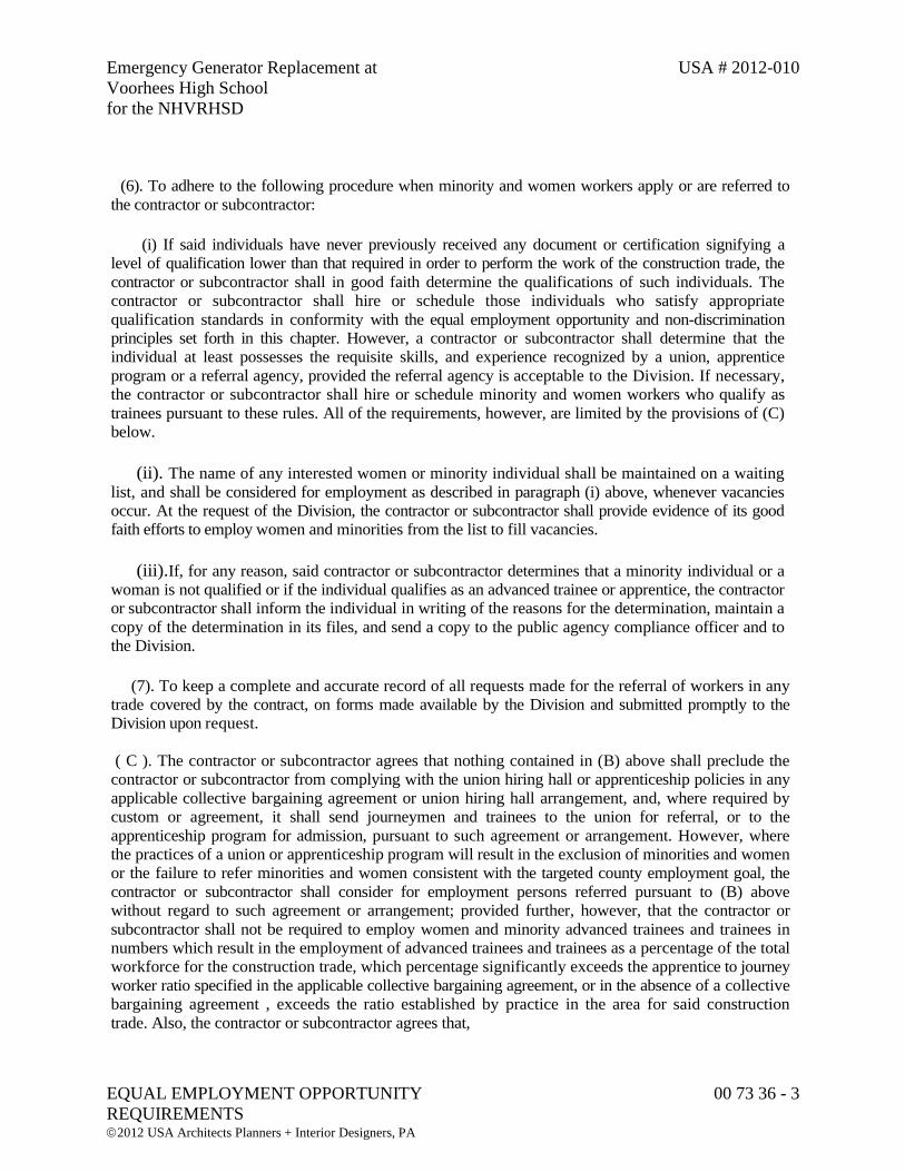
Emergency Generator Replacement at USA # 2012-010
Voorhees High School
for the NHVRHSD
EQUAL EMPLOYMENT OPPORTUNITY 00 73 36 - 3
REQUIREMENTS 2012 USA Architects Planners + Interior Designers, PA
(6). To adhere to the following procedure when minority and women workers apply or are referred to
the contractor or subcontractor:
(i) If said individuals have never previously received any document or certification signifying a
level of qualification lower than that required in order to perform the work of the construction trade, the
contractor or subcontractor shall in good faith determine the qualifications of such individuals. The
contractor or subcontractor shall hire or schedule those individuals who satisfy appropriate
qualification standards in conformity with the equal employment opportunity and non-discrimination
principles set forth in this chapter. However, a contractor or subcontractor shall determine that the
individual at least possesses the requisite skills, and experience recognized by a union, apprentice
program or a referral agency, provided the referral agency is acceptable to the Division. If necessary,
the contractor or subcontractor shall hire or schedule minority and women workers who qualify as
trainees pursuant to these rules. All of the requirements, however, are limited by the provisions of (C)
below.
(ii). The name of any interested women or minority individual shall be maintained on a waiting
list, and shall be considered for employment as described in paragraph (i) above, whenever vacancies
occur. At the request of the Division, the contractor or subcontractor shall provide evidence of its good
faith efforts to employ women and minorities from the list to fill vacancies.
(iii). If, for any reason, said contractor or subcontractor determines that a minority individual or a
woman is not qualified or if the individual qualifies as an advanced trainee or apprentice, the contractor
or subcontractor shall inform the individual in writing of the reasons for the determination, maintain a
copy of the determination in its files, and send a copy to the public agency compliance officer and to
the Division.
(7). To keep a complete and accurate record of all requests made for the referral of workers in any
trade covered by the contract, on forms made available by the Division and submitted promptly to the
Division upon request.
( C ). The contractor or subcontractor agrees that nothing contained in (B) above shall preclude the
contractor or subcontractor from complying with the union hiring hall or apprenticeship policies in any
applicable collective bargaining agreement or union hiring hall arrangement, and, where required by
custom or agreement, it shall send journeymen and trainees to the union for referral, or to the
apprenticeship program for admission, pursuant to such agreement or arrangement. However, where
the practices of a union or apprenticeship program will result in the exclusion of minorities and women
or the failure to refer minorities and women consistent with the targeted county employment goal, the
contractor or subcontractor shall consider for employment persons referred pursuant to (B) above
without regard to such agreement or arrangement; provided further, however, that the contractor or
subcontractor shall not be required to employ women and minority advanced trainees and trainees in
numbers which result in the employment of advanced trainees and trainees as a percentage of the total
workforce for the construction trade, which percentage significantly exceeds the apprentice to journey
worker ratio specified in the applicable collective bargaining agreement, or in the absence of a collective
bargaining agreement , exceeds the ratio established by practice in the area for said construction
trade. Also, the contractor or subcontractor agrees that,
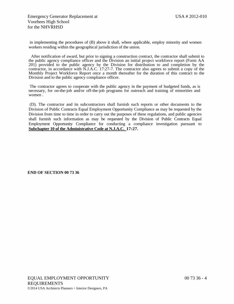
Emergency Generator Replacement at USA # 2012-010
Voorhees High School
for the NHVRHSD
EQUAL EMPLOYMENT OPPORTUNITY 00 73 36 - 4
REQUIREMENTS 2014 USA Architects Planners + Interior Designers, PA
in implementing the procedures of (B) above it shall, where applicable, employ minority and women
workers residing within the geographical jurisdiction of the union.
After notification of award, but prior to signing a construction contract, the contractor shall submit to the public agency compliance officer and the Division an initial project workforce report (Form AA 201) provided to the public agency by the Division for distribution to and completion by the contractor, in accordance with N.J.A.C. 17:27-7. The contractor also agrees to submit a copy of the Monthly Project Workforce Report once a month thereafter for the duration of this contract to the Division and to the public agency compliance officer.
The contractor agrees to cooperate with the public agency in the payment of budgeted funds, as is necessary, for on-the-job and/or off-the-job programs for outreach and training of minorities and women .
(D). The contractor and its subcontractors shall furnish such reports or other documents to the
Division of Public Contracts Equal Employment Opportunity Compliance as may be requested by the
Division from time to time in order to carry out the purposes of these regulations, and public agencies
shall furnish such information as may be requested by the Division of Public Contracts Equal
Employment Opportunity Compliance for conducting a compliance investigation pursuant to
Subchapter 10 of the Administrative Code at N.J.A.C. 17:27.
END OF SECTION 00 73 36
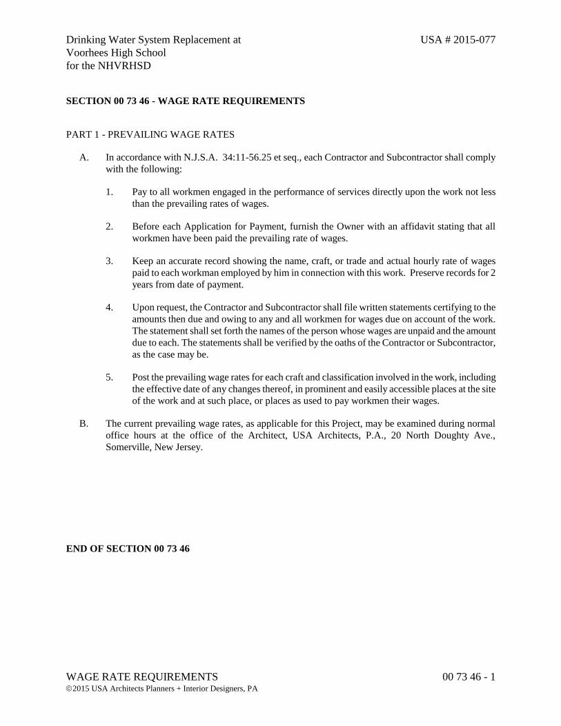
Drinking Water System Replacement at USA # 2015-077
Voorhees High School
for the NHVRHSD
WAGE RATE REQUIREMENTS 00 73 46 - 1 2015 USA Architects Planners + Interior Designers, PA
SECTION 00 73 46 - WAGE RATE REQUIREMENTS
PART 1 - PREVAILING WAGE RATES
A. In accordance with N.J.S.A. 34:11-56.25 et seq., each Contractor and Subcontractor shall comply
with the following:
1. Pay to all workmen engaged in the performance of services directly upon the work not less
than the prevailing rates of wages.
2. Before each Application for Payment, furnish the Owner with an affidavit stating that all
workmen have been paid the prevailing rate of wages.
3. Keep an accurate record showing the name, craft, or trade and actual hourly rate of wages
paid to each workman employed by him in connection with this work. Preserve records for 2
years from date of payment.
4. Upon request, the Contractor and Subcontractor shall file written statements certifying to the
amounts then due and owing to any and all workmen for wages due on account of the work.
The statement shall set forth the names of the person whose wages are unpaid and the amount
due to each. The statements shall be verified by the oaths of the Contractor or Subcontractor,
as the case may be.
5. Post the prevailing wage rates for each craft and classification involved in the work, including
the effective date of any changes thereof, in prominent and easily accessible places at the site
of the work and at such place, or places as used to pay workmen their wages.
B. The current prevailing wage rates, as applicable for this Project, may be examined during normal
office hours at the office of the Architect, USA Architects, P.A., 20 North Doughty Ave.,
Somerville, New Jersey.
END OF SECTION 00 73 46

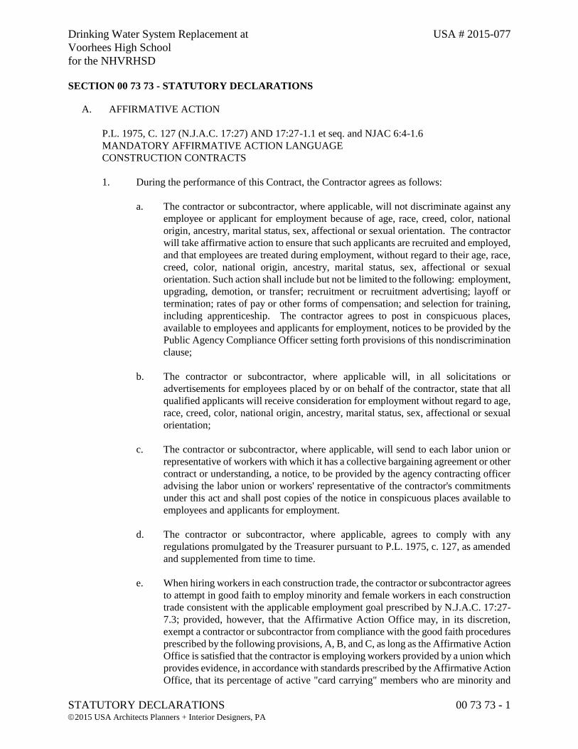
Drinking Water System Replacement at USA # 2015-077
Voorhees High School
for the NHVRHSD
STATUTORY DECLARATIONS 00 73 73 - 1 2015 USA Architects Planners + Interior Designers, PA
SECTION 00 73 73 - STATUTORY DECLARATIONS
A. AFFIRMATIVE ACTION
P.L. 1975, C. 127 (N.J.A.C. 17:27) AND 17:27-1.1 et seq. and NJAC 6:4-1.6
MANDATORY AFFIRMATIVE ACTION LANGUAGE
CONSTRUCTION CONTRACTS
1. During the performance of this Contract, the Contractor agrees as follows:
a. The contractor or subcontractor, where applicable, will not discriminate against any
employee or applicant for employment because of age, race, creed, color, national
origin, ancestry, marital status, sex, affectional or sexual orientation. The contractor
will take affirmative action to ensure that such applicants are recruited and employed,
and that employees are treated during employment, without regard to their age, race,
creed, color, national origin, ancestry, marital status, sex, affectional or sexual
orientation. Such action shall include but not be limited to the following: employment,
upgrading, demotion, or transfer; recruitment or recruitment advertising; layoff or
termination; rates of pay or other forms of compensation; and selection for training,
including apprenticeship. The contractor agrees to post in conspicuous places,
available to employees and applicants for employment, notices to be provided by the
Public Agency Compliance Officer setting forth provisions of this nondiscrimination
clause;
b. The contractor or subcontractor, where applicable will, in all solicitations or
advertisements for employees placed by or on behalf of the contractor, state that all
qualified applicants will receive consideration for employment without regard to age,
race, creed, color, national origin, ancestry, marital status, sex, affectional or sexual
orientation;
c. The contractor or subcontractor, where applicable, will send to each labor union or
representative of workers with which it has a collective bargaining agreement or other
contract or understanding, a notice, to be provided by the agency contracting officer
advising the labor union or workers' representative of the contractor's commitments
under this act and shall post copies of the notice in conspicuous places available to
employees and applicants for employment.
d. The contractor or subcontractor, where applicable, agrees to comply with any
regulations promulgated by the Treasurer pursuant to P.L. 1975, c. 127, as amended
and supplemented from time to time.
e. When hiring workers in each construction trade, the contractor or subcontractor agrees
to attempt in good faith to employ minority and female workers in each construction
trade consistent with the applicable employment goal prescribed by N.J.A.C. 17:27-
7.3; provided, however, that the Affirmative Action Office may, in its discretion,
exempt a contractor or subcontractor from compliance with the good faith procedures
prescribed by the following provisions, A, B, and C, as long as the Affirmative Action
Office is satisfied that the contractor is employing workers provided by a union which
provides evidence, in accordance with standards prescribed by the Affirmative Action
Office, that its percentage of active "card carrying" members who are minority and
Drinking Water System Replacement at USA # 2015-077
Voorhees High School
for the NHVRHSD
STATUTORY DECLARATIONS 00 73 73 - 2 2015 USA Architects Planners + Interior Designers, PA
female workers is equal to or greater than the applicable employment goal prescribed
by N.J.A.C. 17:27-7.3, promulgated by the Treasurer pursuant to P.L. 1975, c. 127, as
amended and supplemented from time to time. The contractor or subcontractor agrees
that a good faith effort shall include compliance with the following procedures:
1) If the contractor or subcontractor has a referral agreement or arrangement with a
union for a construction trade, the contractor or subcontractor shall, within three
days of the contract award, seek assurances from the union that it will cooperate
with the contractor or subcontractor as it fulfills its affirmative action
obligations under this contract and in accordance with the rules promulgated by
the Treasurer pursuant to P.L. 1975, c. 127, as supplemented and amended from
time to time. If the contractor or subcontractor is unable to obtain said
assurances from the construction trade union at least five days prior to the
commencement of construction work, the contractor or subcontractor agrees to
attempt to hire minority and female workers directly, consistent with the
applicable employment goal. If the contractor's or subcontractor's prior
experience with a construction trade union, regardless of whether the union has
provided said assurances, indicates a significant possibility that the trade union
will not refer sufficient minority and female workers consistent with the
applicable employment goal, the contractor or subcontractor agrees to be
prepared to hire minority and female workers directly, consistent with the
applicable employment goal, by complying with the hiring procedures
prescribed under
2) below; and the contractor or subcontractor further agrees to immediately take
said action if it determines or is so notified by the Affirmative Action Office that
the union is not referring minority and female workers consistent with the
applicable employment goal.
3) If the hiring of a work force consistent with the employment goal has not or
cannot be achieved for each construction trade by adhering to the procedures of
(A) above, or if the contractor does not have a referral agreement or
arrangement with a union for a construction trade, the contractor or
subcontractor agrees to take the following actions consistent with the applicable
county employment goals:
a) To notify the Public Agency Compliance Officer, Affirmative Action
Office, and at least one approved minority referral organization of its
manpower needs, and request the referral of minority and female
workers;
b) To notify any minority and female workers who have been listed with it
as awaiting available vacancies;
c) Prior to commencement of work, to request the local construction trade
union, if the contractor or subcontractor has a referral agreement or
arrangement with a union for the construction trade, to refer minority and
female workers to fill job openings;
d) To leave standing requests for additional referral to minority and female
workers with the local construction trade union, if the contractor or
subcontractor has a referral agreement or arrangement with a union for
the construction trade, the State Training and Employment Service and
the other approved referral sources in the area until such time as the work
force is consistent with the employment goal;
e) If it is necessary to lay off some of the workers in a given trade on the
construction site, to assure, consistent with the applicable State and
Drinking Water System Replacement at USA # 2015-077
Voorhees High School
for the NHVRHSD
STATUTORY DECLARATIONS 00 73 73 - 3 2015 USA Architects Planners + Interior Designers, PA
Federal statutes and court decisions, that sufficient minority and female
employees remain on the site consistent with the employment goal; and to
employ any minority and female workers so laid off by the contractor on
any other construction site in the area on which its work force
composition is not consistent with an employment goal established
pursuant to rules implementing P.L. 1975, c. 127;
f) To adhere to the following procedure when minority and female workers
apply or are referred to the contractor or subcontractor:
(i) If said individuals have never previously received any document
or certification signifying a level of qualification lower than that
required, the contractor or subcontractor shall determine the
qualifications of such individuals and if the contractor's or
subcontractor's work force in each construction trade is not
consistent with the applicable employment goal, it shall employ
such persons which satisfy appropriate qualification standards;
provided however, that a contractor or subcontractor shall
determine that the individual at least possesses the skills and
experience recognized by any worker skills and experience
classification determination which may have been made by a
Public Agency Compliance Officer, union, apprentice program
or a referral agency, provided the referral agency is acceptable to
the Affirmative Action Office and provided further, that, if
necessary, the contractor or subcontractor shall hire minority
and female workers who qualify as trainees pursuant to these
regulations. All of the requirements, however, are limited by the
provisions of (C) below.
(ii) If the contractor's or subcontractor's work force is consistent with
the applicable employment goal, the name of said female or
minority group individual shall be maintained on a waiting list
for the first consideration, in the event the contractor's or
subcontractor's work force is no longer consistent with the
applicable employment goal.
(iii) If, for any reason, said contractor or subcontractor determines
that a minority individual or female is not qualified or if the
individual qualifies as an advanced trainee or apprentice, the
contractor or subcontractor shall inform the individual in writing
with the reasons for the determination, maintain a copy in
its files, and send a copy to the Public Agency Compliance
Officer and to the Affirmative Action Office.
g) To keep a complete and accurate record of all requests made for the
referral of workers in any trade covered by the contract, on forms made
available by the Affirmative Action Office and submitted promptly to
that office upon request.
4) The contractor or subcontractor agrees that nothing contained in (B) preceding
provision shall preclude the contractor or subcontractor from complying with
the hiring hall or apprenticeship provisions in any applicable collective
bargaining agreement or hiring hall arrangement, and, where required by custom
or agreement, it shall send journeymen and trainees to the union for referral, or
to the apprenticeship program for admission, pursuant to such agreement or
Drinking Water System Replacement at USA # 2015-077
Voorhees High School
for the NHVRHSD
STATUTORY DECLARATIONS 00 73 73 - 4 2015 USA Architects Planners + Interior Designers, PA
arrangement: provided, however, that where the practices of a union or
apprenticeship program will result in the exclusion of minorities and females
consistent with the county employment goal, the contractor or subcontractor
shall consider for employment persons referred pursuant to said provisions (B)
without regard to such agreement or arrangement; provided further, however,
that the contractor or subcontractor shall not be required to employ female and
minority advanced trainees and trainees in numbers which result in the
employment of advanced trainees and trainees as a percentage of the total work
force for the construction trade, which percentage significantly exceeds the
apprentice to journey worker ratio specified in the applicable collective
bargaining agreement, or in the absence of a collective bargaining agreement,
exceeds the ratio established by practice in the area for said construction trade.
Also, the contractor or subcontractor agrees that, in implementing the
procedures of (B) above, it shall, where applicable, employ minority and female
workers residing within the geographical jurisdiction of the union.
5) The contractor agrees to complete an Initial Project Manning Reports on forms
provided by the Affirmative Action Office or in the form prescribed by the
Affirmative Action Office and submit a copy of said form no later than three
days after signing a construction contract; provided, however, that the public
agency may extend in a particular case the allowable time for submitting the
form to no more than 14 days; and to submit a copy of the Monthly Project
Manning Report once a month thereafter for the duration of this contract to the
Affirmative Action Office and to the Public Agency Compliance Officer. The
contractor agrees to cooperate with the public agency in the payment of
budgeted funds, as is necessary, for on-the-job and off-the-job programs for
outreach and training of minority and female trainees employed on the
construction projects.
6) The contractor and its subcontractors shall furnish such reports or other
documents to the Affirmative Action Office as may be requested by the Office
from time to time in order to carry out the purposes of these regulations, and
public agencies shall furnish such information as may be requested by the
Affirmative Action office for conducting a compliance investigation pursuant to
Subchapter 10 of the Administration Code (NJAC 17:27).
B. DOMESTIC MATERIALS PROCUREMENT
1. Pursuant to N.J.S.A. 18A:18A-20, et seq., only domestic materials and manufactured and
farm products of the United States will be used whenever available, except for any material
which the Owner specifically exempts from this requirement due to inconsistency with public
interest or excessive cost.
END OF SECTION 00 73 73
Drinking Water System Replacement at USA # 2015-077
Voorhees High School
for the NHVRHSD
SUMMARY OF WORK 01 11 00 - 1 2015 USA Architects Planners + Interior Designers, PA
SECTION 01 11 00 - SUMMARY OF WORK (SINGLE PRIME CONTRACT)
PART 1 - GENERAL
1.1 RELATED DOCUMENTS
A. Drawings and general provisions of the Contract, including General and Supplementary Conditions
and Division 01 Sections, apply to work of this Section.
1.2 PROJECT DESCRIPTION
A. The Project consists of Drinking Water System Replacement at Voorhees High School as required
by the Contract Documents for North Hunterdon-Voorhees Regional High School District. The
work is at Voorhees High School, located in Glen Gardner, New Jersey. The replacement project
includes: an above grade pre-manufactured booster pump station with variable speed control vertical
turbine pumps and a separate chemical feed room for water treatment for pH adjustment and
disinfection. The proposed pump station will be placed on top of a below grade 20,000 gallon pre-
cast post-tension concrete tank. A new electrical service will be provided to the proposed pump
station with a dedicated emergency generator. The proposed system will be constructed adjacent to
the existing water system and will be fully tested prior to change-over water service to the school.
After change-over, the existing water system equipment will be removed and the below grade vault
will be filled with sand. The existing 20,000 steel below grade tank will be utilized for non-potable
uses.
B. The extent of the contract work is indicated in the Contract Documents.
1. Local custom and trade union jurisdictional settlement do not control the Scope of Work.
C. The Contractor shall employ his workers for overtime work if required to meet the completion dates,
at no additional cost to the Owner.
D. The scope of the work shall not be limited to what is specifically called out on the drawings or
specifications, but shall include any and all selective demolition as well as any cutting and patching
as may be required to accomplish the intended construction.
1.3 USE OF PREMISES
A. The Contractor shall limit his use of the premises to construction activities in areas indicated; allow
for Owner occupancy and use by the public.
1. Confine operations to areas within contract limits indicated. Portions of the site beyond areas
in which construction operations are indicated are not to be disturbed.
Drinking Water System Replacement at USA # 2015-077
Voorhees High School
for the NHVRHSD
SUMMARY OF WORK 01 11 00 - 2 2015 USA Architects Planners + Interior Designers, PA
2. Keep access drives and entrances serving the premises clear and available to the Owner and
the Owner's employees at all times. Do not use these areas for parking or storage of materials.
Schedule deliveries to minimize space and time requirements for storage of materials and
equipment on site.
3. Contractor shall maintain water source to the High School at all times. The Contractor shall
follow the Water System Sequence of Construction. Any deviation must be approved in
advance with written authorization by Design Engineer.
4. Contractor to fence off work area including open excavation and ensure all equipment and
materials are stored within the fence during non-working hours.
5. Any active open utility trench outside of construction fence must be fully backfilled and
compacted to grade at the end of each work day.
6. Contractor is responsible for pavement and sidewalk repairs/replacement as part of final site
restoration as directed by Owner.
B. Maintain the existing building in a weather tight condition throughout the construction period.
Repair damage caused by constructions operations. Take all precautions necessary to protect the
building and its occupants during the construction period.
1.4 OWNER OCCUPANCY
A. The Owner will occupy the site during the entire construction period. Cooperate with the Owner
during construction operations to minimize conflicts and to facilitate Owner usage. Perform the
work so as not to interfere with the Owner's operations.
1.5 KNOWLEDGE OF CONTRACT REQUIREMENTS
A. The Contractor and his Subcontractor's, Sub-Subcontractor's and material men shall consult in detail
the General Conditions, Supplementary Conditions, all Divisions and Sections of the Specifications,
all Drawings and all Addenda for instructions and requirements pertaining to the Work, and at his
and their cost, shall provide all labor, materials, equipment and services necessary to furnish, install
and complete the work in strict conformance with all provisions thereof.
B. The Scope of Work for the Contract is not necessarily limited to the description of each Section of
the Specifications and the illustrations shown on the Drawings. Include all minor items not
expressly indicated in the Contract Documents, or as might be found necessary as a result of field
conditions, in order to complete the work as it is intended, without any gaps between the various
subdivisions of work of the Contractor and his Subcontractors.
C. The Contractor will be held to be thoroughly familiar with all conditions affecting labor in the
neighborhood of the project including, but not limited to, Unions, incentive pay, procurement, living
and commuting conditions and to have informed his Subcontractors and Sub-Subcontractors thereof.
Drinking Water System Replacement at USA # 2015-077
Voorhees High School
for the NHVRHSD
SUMMARY OF WORK 01 11 00 - 3 2015 USA Architects Planners + Interior Designers, PA
1.6 CONTRACT DOCUMENTS INFORMATION
A. The Contract Documents are prepared in accordance with available information as to existing
conditions and locations. If, during construction, conditions are revealed at variance with the
Contract Documents, notify the Architect promptly so that supplementary instructions may be issued.
B. The Specifications determine the kinds and methods of installation of the various materials, the
Drawings establish the quantities, dimensions and details of materials, the schedules on the
Drawings give the location, type and extent of the materials.
C. Should the Drawings, Specifications or schedules disagree in themselves or with either or both of the
others, the better quality or greater quantity of work or materials shall be performed and provided,
unless otherwise directed in writing by the Architect.
D. Dimensions given on the Drawings govern scale measurements and large scale drawings govern
small scale drawings, except as to anything omitted unless such omission is expressly noted on the
larger scale drawings.
E. The techniques or methods of specifying to record requirements varies throughout text, and may
include "prescriptive", "open generic/descriptive", "compliance with standards", "performance",
"proprietary", or a combination of these. The method used for specifying one unit of work has no
bearing on requirements for another unit of work.
F. Whenever a material, article or piece of equipment is referred to in the singular number in the
Contract Documents, it shall be the same as referring to it in the plural. As many such materials,
articles or pieces of equipment shall be provided as are required to complete the work.
G. With the approval of the Architect and without additional cost to the Owner, the Contractor shall
make all necessary changes or modifications to locations as may be necessary to suit requirements
and conditions at the building and for the proper and conveniently accessible location of all parts of
systems within the project.
H. Small details not usually shown or specified, but necessary for the proper installation and operation
of the work, shall be provided.
I. Cap all incomplete lines, ducts, conduits, openings, etc., until ready for final connection, after which
they shall be thoroughly cleaned and left unobstructed.
PART 2 - PRODUCTS (Not applicable).
PART 3 - EXECUTION (Not applicable).
END OF SECTION 01 11 00

Drinking Water System Replacement at USA # 2015-077
Voorhees High School
for the NHVRHSD
TIME OF COMPLETION 01 11 05 - 1 2015 USA Architects Planners + Interior Designers, PA
SECTION 01 11 05 - TIME OF COMPLETION
PART 1 - GENERAL
1.1 RELATED DOCUMENTS
A. Drawings and general provisions of the Contract, including General and Supplementary Conditions
and other Division 01 Specification Sections, apply to this Section.
1.2 PROJECT SCHEDULE
A. Substantial Completion (upon completion of start-up testing and training and issuance of Certificate
of Occupancy/Certificate of Final Approval) shall be on or before December 22, 2016 and shall be
fully complete including all restoration and contact close out to the satisfaction of the Owner and
Architect on or before June 01, 2017.
1. Prepare and submit itemized Submittal Schedule no later than 14 Calendar days after Notice
to Proceed.
2. Submit Construction Schedule as defined in Specification Section 01 33 00 no later than 14
Calendar days after Notice to Proceed.
3. Complete Submission to the Architect of all required submittals (shop drawings, samples,
catalog cuts, etc.) no later than 30 Calendar days after Notice to Proceed.
4. Contract award anticipated July 2016
5. “On site,” work shall commence on or about July 2016.
6. Once school is in session, all work to be performed within the occupied school will be after
school hours from 3:30 P.M. to 10:30 P.M. All work performed outside the occupied school
can be normal working hours.
7. It is imperative that the contractor properly staff the project (including overtime, after hours,
and weekend work with no additional cost to the Owner) in order to meet Substantial and
Final Completions. The Owner and Owner’s representative will be closely monitoring the
progress of the work throughout the project to ensure that the manpower and progress of the
work is sufficient to meet the contract schedule.
B. Liquidated damages provisions as specified in the General Conditions, AIA Document A201-2007,
included hereto and as modified by this Contract shall apply to the substantial completion date for
the entire project.
END OF SECTION 01 11 05

Drinking Water System Replacement at USA # 2015-077
Voorhees High School
for the NHVRHSD
ALLOWANCES 01 21 00 - 1 2015 USA Architects Planners + Interior Designers, PA
SECTION 01 21 00 - ALLOWANCES
PART 1 - GENERAL
1.1 RELATED DOCUMENTS
A. Drawings and general provisions of the Contract, including General and Supplementary
Conditions and other Division 01 Specification Sections, apply to this Section.
1.2 SUMMARY
A. Section includes administrative and procedural requirements governing allowances.
1. Certain items are specified in the Contract Documents by allowances. Allowances have
been established in lieu of additional requirements and to defer selection of actual
materials and equipment to a later date when direction will be provided to the Contractor.
If necessary, additional requirements will be issued by Change Order.
B. Types of allowances include the following:
1. Contingency allowances.
C. Related Sections:
1. Division 01 Section "Quality Requirements" for procedures governing the use of
allowances for testing and inspecting.
2. Divisions 02 through 49 Sections for items of Work covered by allowances.
1.3 SELECTION AND PURCHASE
A. At the earliest practical date after award of the Contract, advise Architect of the date when final
selection and purchase of each product or system described by an allowance must be completed
to avoid delaying the Work.
B. At Architect's request, obtain proposals for each allowance for use in making final selections.
Include recommendations that are relevant to performing the Work.
C. Purchase products and systems selected by Architect from the designated supplier.
1.4 SUBMITTALS
A. Submit proposals for purchase of products or systems included in allowances, in the form
specified for Change Orders.
Drinking Water System Replacement at USA # 2015-077
Voorhees High School
for the NHVRHSD
ALLOWANCES 01 21 00 - 2 2015 USA Architects Planners + Interior Designers, PA
B. Submit invoices or delivery slips to show actual quantities of materials delivered to the site for
use in fulfillment of each allowance.
C. Submit time sheets and other documentation to show labor time and cost for installation of
allowance items that include installation as part of the allowance.
D. Coordinate and process submittals for allowance items in same manner as for other portions of
the Work.
1.5 COORDINATION
A. Coordinate allowance items with other portions of the Work. Furnish templates as required to
coordinate installation.
1.6 CONTINGENCY ALLOWANCES
A. Use the contingency allowance only as directed by Architect for Owner's purposes and only by
Change Orders that indicate amounts to be charged to the allowance.
B. Contractor's labor and material costs only will be billed against the contingency allowance. All
overhead, profit, supervision, project management, delivery, installation, taxes, insurance,
equipment rental, and similar costs ordered by Owner under the contingency allowance shall be
included in the overall lump sum of the Bid.
C. At Project closeout, credit unused amounts remaining in the contingency allowance to Owner
by Change Order.
1.7 ADJUSTMENT OF ALLOWANCES
A. Allowance Adjustment: To adjust allowance amounts, prepare a Change Order proposal based
on the difference between purchase amount and the allowance, multiplied by final measurement
of work-in-place where applicable. If applicable, include reasonable allowances for cutting
losses, tolerances, mixing wastes, normal product imperfections, and similar margins.
1. Include installation costs in purchase amount only where indicated as part of the
allowance.
2. If requested, prepare explanation and documentation to substantiate distribution of
overhead costs and other margins claimed.
3. Submit substantiation of a change in scope of work, if any, claimed in Change Orders
related to unit-cost allowances.
4. Owner reserves the right to establish the quantity of work-in-place by independent
quantity survey, measure, or count.
B. Submit claims for increased costs because of a change in scope or nature of the allowance
described in the Contract Documents, whether for the purchase order amount or Contractor's
handling, labor, installation, overhead, and profit.
Drinking Water System Replacement at USA # 2015-077
Voorhees High School
for the NHVRHSD
ALLOWANCES 01 21 00 - 3 2015 USA Architects Planners + Interior Designers, PA
1. Do not include Contractor's or subcontractor's indirect expense in the Change Order cost
amount unless it is clearly shown that the nature or extent of work has changed from what
could have been foreseen from information in the Contract Documents.
2. No change to Contractor's indirect expense is permitted for selection of higher- or lower-
priced materials or systems of the same scope and nature as originally indicated.
PART 2 - PRODUCTS (Not Used)
PART 3 - EXECUTION
3.1 EXAMINATION
A. Examine products covered by an allowance promptly on delivery for damage or defects. Return
damaged or defective products to manufacturer for replacement.
3.2 PREPARATION
A. Coordinate materials and their installation for each allowance with related materials and
installations to ensure that each allowance item is completely integrated and interfaced with
related work.
3.3 SCHEDULE OF ALLOWANCES
A. Allowance No. 1; (Contingency Allowance): Include a contingency allowance of $50,000.00
for use according to Owner's instructions.
END OF SECTION 01 21 00

Drinking Water System Replacement at USA # 2015-077
Voorhees High School
for the NHVRHSD
PRODUCT SUBSTITUTIONS 01 25 00- 1 2015 USA Architects Planners + Interior Designers, PA
SECTION 01 25 00 - PRODUCT SUBSTITUTIONS
PART 1 - GENERAL
1.1 RELATED DOCUMENTS
A. Drawings and general provisions of the Contract, including General and Supplementary Conditions
and other Division 01 Specification Sections, apply to this Section.
1.2 SUMMARY
A. This Section specifies administrative and procedural requirements for handling requests for
substitutions made after award of the Contract.
B. Standards: Refer to Section "Reference Standards and Definitions" for applicability of industry
standards to products specified.
C. Procedural requirements governing the Contractor's selection of products and product options are
included under Section "Materials and Equipment."
1.3 DEFINITIONS
A. Definitions used in this Article are not intended to change or modify the meaning of other terms used
in the Contract Documents.
B. Substitutions: Requests for changes in products, materials, equipment, and methods of construction
required by Contract Documents proposed by the Contractor after award of the Contract are
considered requests for "substitutions." The following are not considered substitutions:
a. Substitutions requested by Bidders during the bidding period, and accepted prior to
award of Contract, are considered as included in the Contract Documents and are not
subject to requirements specified in this Section for substitutions.
b. Revisions to Contract Documents requested by the Owner or Architect.
c. Specified options of products and construction methods included in Contract
Documents.
d. The Contractor's determination of and compliance with governing regulations and
orders issued by governing authorities.
1.4 SUBMITTALS
A. Substitution Request Submittal: Requests for substitution will be considered if received within 15
days after Notice to Proceed. Requests received more than 15 days after Notice to Proceed may be
considered or rejected at the discretion of the Architect.
Drinking Water System Replacement at USA # 2015-077
Voorhees High School
for the NHVRHSD
PRODUCT SUBSTITUTIONS 01 25 00- 2 2015 USA Architects Planners + Interior Designers, PA
1. Submit 3 copies of each request for substitution for consideration. Submit requests in the
form and in accordance with procedures required for Change Order proposals.
2. Identify the product, or the fabrication or installation method to be replaced in each request.
Include related Specification Section and Drawing numbers. Provide complete
documentation showing compliance with the requirements for substitutions, and the following
information, as appropriate:
a. Product Data, including Drawings and descriptions of products, fabrication and
installation procedures.
b. Samples, where applicable or requested.
c. A detailed comparison of significant qualities of the proposed substitution with those
of the Work specified. Significant qualities may include elements such as size, weight,
durability, performance and visual effect.
d. Coordination information, including a list of changes or modifications needed to other
parts of the Work and to construction performed by the Owner and separate
Contractors, that will become necessary to accommodate the proposed substitution.
e. A statement indicating the substitution's effect on the Contractor's Construction
Schedule compared to the schedule without approval of the substitution. Indicate the
effect of the proposed substitution on overall Contract Time.
f. Cost information, including a proposal of the net change, if any in the Contract Sum.
g. Certification by the Contractor that the substitution proposed is equal-to or better in
every significant respect to that required by the Contract Documents, and that it will
perform adequately in the application indicated. Include the Contractor's waiver of
rights to additional payment or time, that may subsequently become necessary because
of the failure of the substitution to perform adequately.
3. Architect's Action: Within one week of receipt of the request for substitution, the Architect
will request additional information or documentation necessary for evaluation of the request.
Within 2 weeks of receipt of the request, or one week of receipt of the additional information
or documentation, which ever is later, the Architect will notify the Contractor of acceptance or
rejection of the proposed substitution. If a decision on use of a proposed substitute cannot be
made or obtained within the time allocated, use the product specified by name. Acceptance
will be in the form of a Change Order.
a. The Architect will review each request for substitution only once. The Contractor will
be required to reimburse the Architect at his hourly rate, for any reviews which are
required, or requested, beyond the initial review.
PART 2 - PRODUCTS (Not Applicable)
PART 3 - EXECUTION
3.1 SUBSTITUTIONS
A. Substitutions may be permitted by the Architect, if, in his opinion, the requirements of the proposed
substitution comply with the requirements specified for the material, article or piece of equipment;
however, the Architect is not required to permit substitution pursuant to; “Whitten Corporation vs.
Drinking Water System Replacement at USA # 2015-077
Voorhees High School
for the NHVRHSD
PRODUCT SUBSTITUTIONS 01 25 00- 3 2015 USA Architects Planners + Interior Designers, PA
Paddock, Incorporated,” United States District Court, Massachusetts, April 12, 1974, affirmed by the
Federal First Circuit Court, December 14, 1974, and the United States Supreme Court, 1988.
B. The Architect has no obligation, after award of contract, to consider any brand other than those
named in the Contract Documents. However, the Contractor may submit substitutes to the Architect
for review, fully documented and certified, and accompanied by his proposal for a deduction in the
Contract Sum.
C. Conditions: The Contractor's substitution request will be received and considered by the Architect
when one or more of the following conditions are satisfied, as determined by the Architect; otherwise
requests will be returned without action except to record noncompliance with these requirements.
a. Extensive revisions to Contract Documents are not required.
b. Proposed changes are in keeping with the general intent of Contract Documents.
c. The request is timely, fully documented and properly submitted.
d. The request is directly related to an "or equal" clause or similar language in the
Contract Documents.
e. The specified product or method of construction cannot be provided within the
Contract Time. The request will not be considered if the product or method cannot be
provided as a result of failure to pursue the Work promptly or coordinate activities
properly.
f. The specified product or method of construction cannot receive necessary approval by
a governing authority, and the requested substitution can be approved.
g. A substantial advantage is offered the Owner, in terms of cost, time, energy
conservation or other considerations of merit, after deducting offsetting responsibilities
the Owner may be required to bear. Additional responsibilities for the Owner may
include additional compensation to the Architect for redesign and evaluation services,
increased cost of other construction by the Owner or separate Contractors, and similar
considerations.
h. The specified product or method of construction cannot be provided in a manner that is
compatible with other materials, and where the Contractor certifies that the substitution
will overcome the incompatibility.
i. The specified product or method of construction cannot be coordinated with other
materials, and where the Contractor certifies that the proposed substitution can be
coordinated.
j. The specified product or method of construction cannot provide a warranty required by
the Contract Documents and where the Contractor certifies that the proposed
substitution provide the required warranty.
k. Where a proposed substitution involves more than one prime Contractor, each
Contractor shall cooperate with the other Contractors involved to coordinate the Work,
provide uniformity and consistency, and to assure compatibility of products.
D. The Contractor's submittal and Architect's acceptance of Shop Drawings, Product Data or Samples
that relate to construction activities not complying with the Contract Documents does not constitute
an acceptable or valid request for substitution, nor does it constitute approval.
E. Refer to SUBSTITUTION REQUEST FORMS ON THE FOLLOWING PAGES.
END OF SECTION 01 25 00
Drinking Water System Replacement at USA # 2015-077
Voorhees High School
for the NHVRHSD
PRODUCT SUBSTITUTIONS 01 25 00- 4 2015 USA Architects Planners + Interior Designers, PA
REQUEST FOR SUBSTITUTION
Submit a copy of this form for each requested substitution. Fill in all blanks, check all boxes that apply
and attach all necessary supporting data.
SUBSTITUTION NO.:
Specified Item:
Specification Section(s)/Paragraph(s):
Drawing Number(s):
Proposed Substitute:
(include, as applicable, manufacturer’s name & address, trade name & model number of product and name of fabricator or supplier)
Reason for Proposed Substitution:
Net Change to Contract Sum: No Change Deduct $_________ Add $________
Change to Contract Time: No Change ________ Days ________
The following required supporting documents are attached (Check all that apply):
Complete Product Data
Itemized comparison of properties of proposed product to specified product.
List of other projects on which proposed has been used, with project name, design professional’s
name and owner contact.
List of maintenance services and replacement materials available.
Statement of effect of substitution on construction schedule.
Description of change that will be required in other work or products if substitute product is approved.
Additional Information:
Drinking Water System Replacement at USA # 2015-077
Voorhees High School
for the NHVRHSD
PRODUCT SUBSTITUTIONS 01 25 00- 5 2015 USA Architects Planners + Interior Designers, PA
REQUEST FOR SUBSTITUTION
The undersigned testifies that he/she:
Is submitting this substitution request within the limits set forth in the Contract Documents.
Has investigated the proposed product and determined that it is equal or better than the specified
product.
Will provide the same warranty for the proposed product as for the specified product.
Will coordinate installation and make other changes as required for the work to be complete in all
respects, including: (a) redesign and (b) additional components and capacity required by other work
affected by the change.
Waives all claims for additional costs for evaluation of the substitution request, redesign if required,
and reapproval by authorities having jurisdiction, if required.
Waives reimburse the Owner for additional costs for evaluation of the substitution request, redesign if
required, and reapproval by authorities having jurisdiction, if required.
Contractor’s Signature: __________________________________________________________
Typed or Printed Name: __________________________________________________________
Title: __________________________________________________________
Company: __________________________________________________________
Address: __________________________________________________________
Phone Number: ___________________________________________________________
Owner Approval: _____________________________ Date: __________________
Construction Manager Approval: ____________________________ Date: __________________ If Applicable
USA Architects, P.A. Approval: _____________________________ Date: __________________
Consulting Engineer Approval: _____________________________ Date: __________________

Drinking Water System Replacement at USA # 2015-077
Voorhees High School
for the NHVRHSD
MODIFICATION PROCEDURES 01 26 00 - 1 2015 USA Architects Planners + Interior Designers, PA
SECTION 01 26 00 - MODIFICATION PROCEDURES
PART 1 - GENERAL
1.1 RELATED DOCUMENTS
A. Drawings and general provisions of Contract, including General and Supplementary Conditions and
other Division 01 Specification sections, apply to this section.
1.2 SUMMARY
A. This section specifies administrative and procedural requirements for handling and processing
Contract modifications.
B. Related Sections: The following sections contain requirements that relate to this section:
1. Division 01 Section "Submittals" for requirements for the Contractor's Construction Schedule.
2. Division 01 Section "Application for Payment" for administrative procedures governing
applications for payment.
3. Division 01 Section "Product Substitutions" for administrative procedures for handling
requests for substitutions made after award of the Contract.
1.3 CHANGE ORDER PROPOSAL REQUESTS
A. Owner-Initiated Proposal Requests: Proposed changes in the Work that will require adjustment to
the Contract Sum or Contract Time will be issued by the Architect, with a detailed description of the
proposed change and supplemental or revised Drawings and Specifications, if necessary.
1. Proposal requests issued by the Architect are for information only. Do not consider them an
instruction either to stop work in progress, or to execute the proposed change.
2. Unless otherwise indicated in the proposal request, within 20 days of receipt of the proposal
request, submit to the Architect for the Owner's review an estimate of cost necessary to
execute the proposed change.
a. Include a list of quantities of products to be purchased and unit costs, along with the
total amount of purchases to be made. Where requested, furnish survey data to
substantiate quantities.
b. Indicate applicable taxes, delivery charges, equipment rental, and amounts of trade
discounts.
c. Include a statement indicating the effect the proposed change in the Work will have on
the Contract Time.
Drinking Water System Replacement at USA # 2015-077
Voorhees High School
for the NHVRHSD
MODIFICATION PROCEDURES 01 26 00 - 2 2015 USA Architects Planners + Interior Designers, PA
B. Contractor-Initiated Change Order Proposal Requests: When latent or other unforeseen conditions
require modifications to the Contract, the Contractor may propose changes by submitting a request
for a change to the Architect.
1. Include a statement outlining the reasons for the change and the effect of the change on the
Work. Provide a complete description of the proposed change. Indicate the effect of the
proposed change on the Contract Sum and Contract Time.
2. Include a list of quantities of products to be purchased and unit costs along with the total
amount of purchases to be made. Where requested, furnish survey data to substantiate
quantities.
3. Indicate applicable taxes, delivery charges, equipment rental, and amounts of trade discounts,
if allowed and or applicable.
4. Comply with requirements in Section "Product Substitutions" if the proposed change in the
Work requires the substitution of one product or system for a product or system specified.
C. Proposal Request Form: Use AIA Document G 709 for Change Order Proposal Requests.
1.4 CHANGES IN THE WORK
A. Tabulate cost breakdown into subcontracts and trades for each of which the quantity, labor, material,
other cost and resulting final cost per unit shall be indicated. Quantity, labor, material, other cost
and cost per unit generally include but are not necessarily limited to the following:
1. Quantity; total number of items for each portion or unit of work as determined from the
change.
2. Labor; on site labor for the handling and installation of material from point of delivery at site.
3. Material; cost of material as delivered to the site for installation and erection.
4. Other cost; rental equipment, depreciation, site office, administration, overhead and profit,
testing survey and layout, samples and all other costs not included in labor and material.
B. When a change in the work includes a category or categories of work both added to and deducted
from the Contract, the total quantities of added work and of deleted work shall be determined
separately for each category and the appropriate unit price or net cost of the work shall be applied to
the difference between the two total quantities.
C. Unit prices shall be inclusive of all costs and shall be applied to units of measure as defined in the
specifications for each category of work.
D. For all extra work performed by the Contractor, the gross cost to the Owner shall include the net cost
of the work to the Contractor plus an allowance for overhead and profit not to exceed, (See General
Conditions, Article 7), of the net cost.
Drinking Water System Replacement at USA # 2015-077
Voorhees High School
for the NHVRHSD
MODIFICATION PROCEDURES 01 26 00 - 3 2015 USA Architects Planners + Interior Designers, PA
E. For all extra work performed by a Subcontractor, the gross cost to the Owner shall include the net
cost of the work by the Subcontractor plus an allowance for overhead and profit not to exceed, (See
General Conditions, Article 7), of his net cost, plus the General Contractor's overhead and profit not
to exceed, (See General Conditions, Article 7), of the Subcontractor's net cost. In no case shall the
total allowance for overhead and profit exceed, (See General Conditions, Article 7), of the net cost of
the work.
F. Net cost of extra work shall be the actual or prorated cost of:
1. In all cases to be in compliance with the General Conditions, Article 7.
G. Gross costs shall be net costs plus allowances listed in the General Conditions, Article 7. Such
allowances shall be inclusive of all costs for construction superintendent, supervision, engineering,
overhead, profit, administrative and site office expenses and all other general expenses.
1.5 CONSTRUCTION CHANGE DIRECTIVE
A. Construction Change Directive: When the Owner and Contractor are not in total agreement on the
terms of a Change Order Proposal Request, the Architect may issue a Construction Change Directive
on AIA Form G714, instructing the Contractor to proceed with a change in the Work, for subsequent
inclusion in a Change Order.
1. The Construction Change Directive will contain a complete description of the change in the
Work and designate the method to be followed to determine change in the Contract Sum or
Contract Time.
B. Documentation: Maintain detailed records on a time and material basis of work required by the
Construction Change Directive.
1. After completion of the change, submit an itemized account and supporting data necessary to
substantiate cost and time adjustments to the Contract.
1.6 CHANGE ORDER PROCEDURES
A. Upon the Owner's approval of a Change Order Proposal Request, the Architect will issue a Change
Order for signatures of the Owner and Contractor on AIA Form G701, as provided in the Conditions
of the Contract.
PART 2 - PRODUCTS (Not Applicable)
PART 3 - EXECUTION (Not Applicable)
END OF SECTION 01 26 00

Drinking Water System Replacement at USA # 2015-077
Voorhees High School
for the NHVRHSD
APPLICATIONS FOR PAYMENT 01 29 00 - 1 2015 USA Architects Planners + Interior Designers, PA
SECTION 01 29 00 - APPLICATIONS FOR PAYMENT
PART 1 - GENERAL
1.1 RELATED DOCUMENTS
A. Drawings and general provisions of Contract, including General and Supplementary Conditions and
other Division 01 Specification Sections, apply to this Section.
1.2 SUMMARY
A. This Section specifies administrative and procedural requirements governing the Contractor's
Applications for Payment.
1. Coordinate the Schedule of Values and Applications for Payment with the Contractor's
Construction Schedule, List of Subcontracts, and Submittal Schedule.
1.3 SCHEDULE OF VALUES
A. The Contractor shall coordinate preparation of the Schedule of Values with preparation of the
Contractor's Construction Schedule.
1. Correlate line items in the Schedule of Values with other required administrative schedules
and forms, including:
a. Contractor's construction schedule.
b. Application for Payment form.
c. List of subcontractors.
d. Schedule of alternates.
e. List of products.
f. List of principal suppliers and fabricators.
2. Submit the Schedule of Values to the Engineer/Architect and Owner at the earliest feasible
date, but in no case later than 7 days before the date scheduled for submittal of the initial
Application for Payment.
a. Submit 3 copies of Schedule of Values to Engineer/Architect and Owner.
B. Format and Content: Use the Project Manual Table of Contents as a guide to establish the format for
the Schedule of Values.
1. Identification: Include the following Project identification on the Schedule of Values:
a. Project name and location.
b. Name of the Architect.
c. Project number.
Drinking Water System Replacement at USA # 2015-077
Voorhees High School
for the NHVRHSD
APPLICATIONS FOR PAYMENT 01 29 00 - 2 2015 USA Architects Planners + Interior Designers, PA
d. Contractor's name and address.
e. Date of submittal.
2. Arrange the Schedule of Values in a tabular form with separate columns to indicate the
following for each item listed:
a. Generic name.
b. Related Specification Section.
c. Name of subcontractor.
d. Name of manufacturer or fabricator.
e. Name of supplier.
f. Change Orders (numbers) that have affected value.
g. Dollar value.
h. Percentage of Contract Sum to the nearest one-hundredth percent, adjusted to total 100
percent.
3. Provide a breakdown of the Contract Sum in sufficient detail to facilitate continued evaluation
of Applications for Payment and progress reports. Break principal subcontract amounts down
into several line items.
4. Round amounts off to the nearest whole dollar; the total shall equal the Contract Sum.
5. For each part of the Work where an Application for Payment may include materials or
equipment, purchased or fabricated and stored, but not yet installed, provide separate line
items on the Schedule of Values for initial cost of the materials, for each subsequent stage of
completion, and for total installed value of that part of the Work.
6. Tabulate schedule into subcontracts and trades for each of which the quantity, labor,
materials, other cost and resulting final cost per unit shall be indicated. Quantity, labor,
materials, other cost and cost per unit generally include but are not necessarily limited to the
following:
a. Quantity; total number of times for each portion or unit of work as determined from the
Contract Documents.
b. Labor; on site labor for the handling and installation of material from point of delivery
at site.
c. Material; cost of materials as delivered to the site for installation and erection.
d. Other cost; rental equipment, depreciation, site office, administration, overhead and
profit, testing, survey and layout, samples and all other costs not included in labor and
material.
e. Cost per unit; total of labor, material and other Cost for each portion or unit of work
derived from the total quantity of same.
1.4 PROGRESS PAYMENTS
A. Based upon application for payments submitted to the Architect and Owner, by the Contractor, on
the specified day of each month and Certificate of Payment certified by the Engineer/Architect, the
Owner will make progress payments on account of the Contract Sum to the Contractor as follows:
Drinking Water System Replacement at USA # 2015-077
Voorhees High School
for the NHVRHSD
APPLICATIONS FOR PAYMENT 01 29 00 - 3 2015 USA Architects Planners + Interior Designers, PA
1. In making progress payments, there shall be retained two percent (2%) of the approved
amount when the outstanding balance of the contract exceeds $500,000, and 5% of the
amount due on each partial payment when the outstanding balance of the contract is $500,000
or less, until final completion and acceptance of all work covered by the Contract, including
the completion of all corrective or punch list items.
2. For each day delay in the Contractor's submission of an application for payment acceptable to
the Engineer/Architect and Owner, the Owner may delay one day in making his progress
payment.
1.5 APPLICATIONS FOR PAYMENT:
A. The Contractor's monthly application for payment shall be in the same schedule form as the schedule
of values, reflecting the same items. Unit costs shall be realistic for their part of the work.
B. Each Application for Payment shall be consistent with previous applications and payments as
approved by and paid for by the Owner.
1. The initial Application for Payment, the Application for Payment at time of Substantial
Completion, and the final Application for Payment involve additional requirements.
C. Payment Application Times: Each Payment Application shall be made at the end of each month and
shall be based upon the entire month’s completed work. A “pencil copy” shall be submitted on or
about the 25th of each month showing the projected completion of work for the month, for review.
D. In accordance with N.J.S.A. 2A:30A-2a the following payment procedure shall be in effect:
1. The alternate procedure for local units applies when local policies require governing body
approval authorizing the payment of bills. In addition to ensuring the contractor has
performed in accordance with the contract and that the work has been approved and certified
by the owner or the owner’s “authorized approving agent,” the following provisions apply:
2. The 20th calendar day deadline of the default procedure to approve and certify, or decide to
withhold full or partial payment is deferred until the public meeting following 20 calendar
days of the billing date, at which time the bill must be approved for payment or notice
provided as to why the bill or any portion of it will not be approved.
3. If the billing is approved, the 30-day payment requirement of the default is replaced by the
requirement that the bill be paid in the payment cycle following the meeting.
E. Payment Application Forms: Use AIA Document G 702 and Continuation Sheets G 703 as the form
for Application for Payment.
F. Application Preparation: Complete every entry on the form, including notarization and execution by
person authorized to sign legal documents on behalf of the Contractor. Incomplete applications will
be returned without action.
Drinking Water System Replacement at USA # 2015-077
Voorhees High School
for the NHVRHSD
APPLICATIONS FOR PAYMENT 01 29 00 - 4 2015 USA Architects Planners + Interior Designers, PA
1. Entries shall match data on the Schedule of Values and Contractor's Construction Schedule.
Use updated schedules if revisions have been made.
2. Include amounts of Change Orders and Construction Change Directives issued prior to the
last day of the construction period covered by the application.
G. Transmittal: Submit 3 executed copies of each Application for Payment to the Owner by means
ensuring receipt within 24 hours; each copy shall be complete, including waivers of lien and similar
attachments, when required.
1. Transmit each copy with a transmittal form listing attachments, and recording appropriate
information related to the application in a manner acceptable to the Architect.
H. Waivers of Mechanics Lien: Submit waivers of mechanics lien from every entity who may lawfully
be entitled to file a mechanics lien arising out of the Contract, and related to the Work covered by the
payment.
1. Submit final Application for Payment with final waivers from every entity involved with
performance of Work covered by the application who could lawfully be entitled to a lien.
2. Waiver Forms: Submit waivers of lien on forms, and executed in a manner, acceptable to
Owner.
I. Initial Application for Payment: Administrative actions and submittals that must precede or coincide
with submittal of the first Application for Payment include the following:
1. List of subcontractors.
2. List of principal suppliers and fabricators.
3. Schedule of Values.
4. Contractor's Construction Schedule (preliminary if not final).
5. Schedule of principal products.
6. Schedule of unit prices.
7. Submittal Schedule (preliminary if not final).
8. List of Contractor's staff assignments.
9. List of Contractor's principal consultants.
10. Copies of building permits
11. Copies of authorizations and licenses from governing authorities for performance of the
Work.
Drinking Water System Replacement at USA # 2015-077
Voorhees High School
for the NHVRHSD
APPLICATIONS FOR PAYMENT 01 29 00 - 5 2015 USA Architects Planners + Interior Designers, PA
12. Initial progress report.
13. Report of pre-construction meeting.
14. Certificates of insurance and insurance policies.
15. Performance and payment bonds (if required).
16. Data needed to acquire Owner's insurance.
J. Final Payment Application: Administrative actions and submittals which must precede or coincide
with submittal of the final payment Application for Payment include the following:
1. Completion of Project closeout requirements.
2. Completion of punch list items.
3. Transmittal of required Project construction records to Owner.
4. Proof that taxes, fees and similar obligations have been paid.
5. Removal of temporary facilities and services.
6. Removal of surplus materials, rubbish and similar elements.
7. Contractor's Affidavit of Payments of Debts & Claims - AIA Document G706.
8. Contractor's Affidavit of Release of Liens - AIA Document G706A.
9. Consent of Surety to Final Payment - AIA Document G707.
1.6 WAIVER OF LIENS
A. The Contractor, for himself, and for all Subcontractors and material men, agrees that no mechanic's
lien or other claim shall be filed or maintained by the Contractor or by any Subcontractor, material
man, laborer or any other person whatsoever for, or on account of any work performed or materials
furnished under this Contract. This agreement shall execute and deliver a separate waiver of Liens
in form and substance satisfactory to the Owner contemporaneously with the execution of the
Owner-Contractor Agreement and before any work is begun at the site.
B. In every subcontract entered into by the Contractor after execution of this Contract or in connection
herewith, the Contractor shall incorporate a provision, similar to the foregoing paragraph, to the
effect that neither the Subcontractor nor any party acting through or under him shall file or maintain
any mechanic's lien or other claim against the Owner in connection with the Work.
PART 2 - PRODUCTS (Not Applicable)
Drinking Water System Replacement at USA # 2015-077
Voorhees High School
for the NHVRHSD
APPLICATIONS FOR PAYMENT 01 29 00 - 6 2015 USA Architects Planners + Interior Designers, PA
PART 3 - EXECUTION (Not Applicable)
END OF SECTION 01 29 00
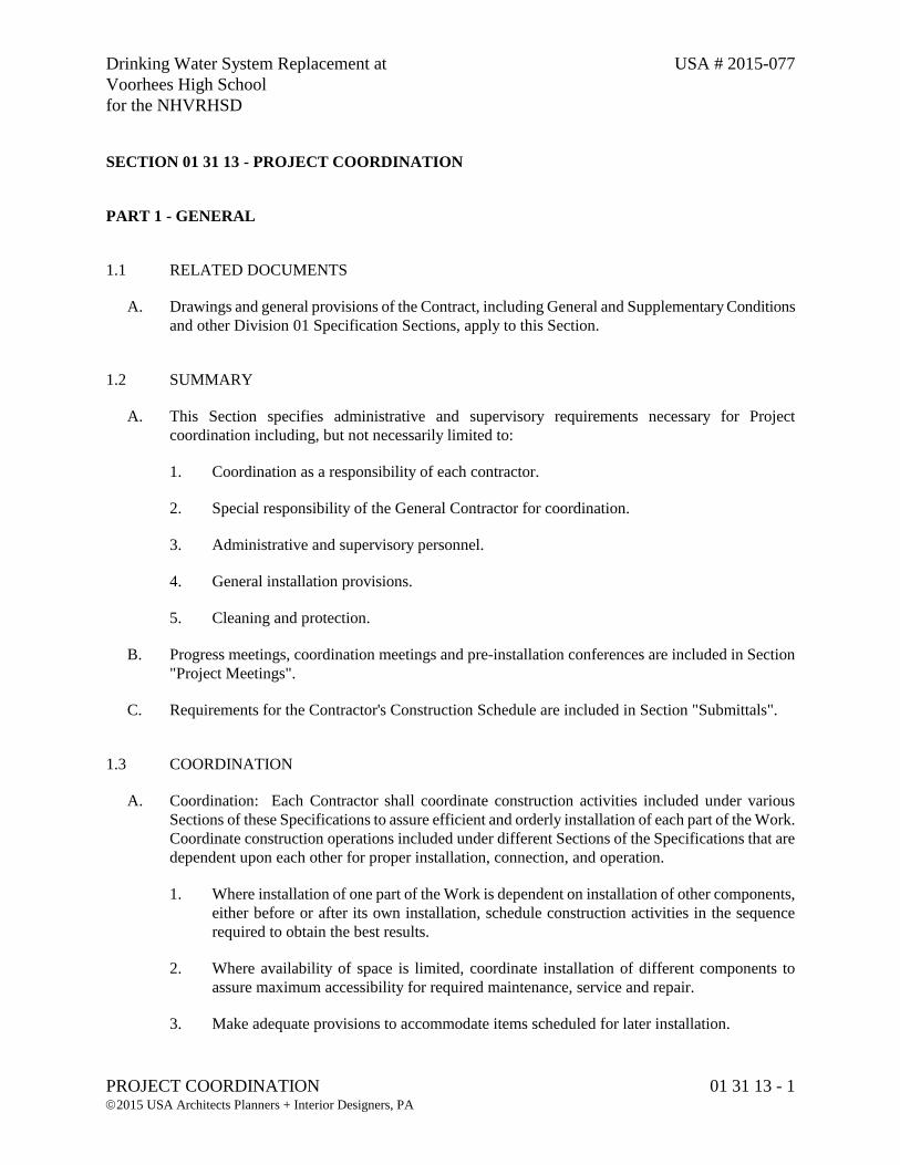
Drinking Water System Replacement at USA # 2015-077
Voorhees High School
for the NHVRHSD
PROJECT COORDINATION 01 31 13 - 1 2015 USA Architects Planners + Interior Designers, PA
SECTION 01 31 13 - PROJECT COORDINATION
PART 1 - GENERAL
1.1 RELATED DOCUMENTS
A. Drawings and general provisions of the Contract, including General and Supplementary Conditions
and other Division 01 Specification Sections, apply to this Section.
1.2 SUMMARY
A. This Section specifies administrative and supervisory requirements necessary for Project
coordination including, but not necessarily limited to:
1. Coordination as a responsibility of each contractor.
2. Special responsibility of the General Contractor for coordination.
3. Administrative and supervisory personnel.
4. General installation provisions.
5. Cleaning and protection.
B. Progress meetings, coordination meetings and pre-installation conferences are included in Section
"Project Meetings".
C. Requirements for the Contractor's Construction Schedule are included in Section "Submittals".
1.3 COORDINATION
A. Coordination: Each Contractor shall coordinate construction activities included under various
Sections of these Specifications to assure efficient and orderly installation of each part of the Work.
Coordinate construction operations included under different Sections of the Specifications that are
dependent upon each other for proper installation, connection, and operation.
1. Where installation of one part of the Work is dependent on installation of other components,
either before or after its own installation, schedule construction activities in the sequence
required to obtain the best results.
2. Where availability of space is limited, coordinate installation of different components to
assure maximum accessibility for required maintenance, service and repair.
3. Make adequate provisions to accommodate items scheduled for later installation.
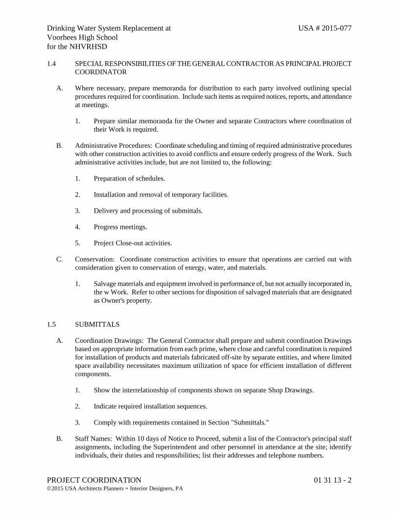
Drinking Water System Replacement at USA # 2015-077
Voorhees High School
for the NHVRHSD
PROJECT COORDINATION 01 31 13 - 2 2015 USA Architects Planners + Interior Designers, PA
1.4 SPECIAL RESPONSIBILITIES OF THE GENERAL CONTRACTOR AS PRINCIPAL PROJECT
COORDINATOR
A. Where necessary, prepare memoranda for distribution to each party involved outlining special
procedures required for coordination. Include such items as required notices, reports, and attendance
at meetings.
1. Prepare similar memoranda for the Owner and separate Contractors where coordination of
their Work is required.
B. Administrative Procedures: Coordinate scheduling and timing of required administrative procedures
with other construction activities to avoid conflicts and ensure orderly progress of the Work. Such
administrative activities include, but are not limited to, the following:
1. Preparation of schedules.
2. Installation and removal of temporary facilities.
3. Delivery and processing of submittals.
4. Progress meetings.
5. Project Close-out activities.
C. Conservation: Coordinate construction activities to ensure that operations are carried out with
consideration given to conservation of energy, water, and materials.
1. Salvage materials and equipment involved in performance of, but not actually incorporated in,
the w Work. Refer to other sections for disposition of salvaged materials that are designated
as Owner's property.
1.5 SUBMITTALS
A. Coordination Drawings: The General Contractor shall prepare and submit coordination Drawings
based on appropriate information from each prime, where close and careful coordination is required
for installation of products and materials fabricated off-site by separate entities, and where limited
space availability necessitates maximum utilization of space for efficient installation of different
components.
1. Show the interrelationship of components shown on separate Shop Drawings.
2. Indicate required installation sequences.
3. Comply with requirements contained in Section "Submittals."
B. Staff Names: Within 10 days of Notice to Proceed, submit a list of the Contractor's principal staff
assignments, including the Superintendent and other personnel in attendance at the site; identify
individuals, their duties and responsibilities; list their addresses and telephone numbers.
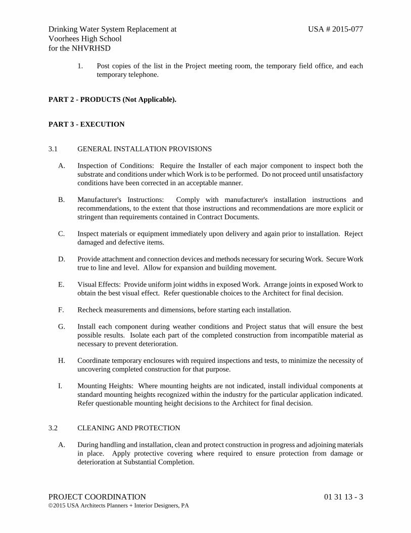
Drinking Water System Replacement at USA # 2015-077
Voorhees High School
for the NHVRHSD
PROJECT COORDINATION 01 31 13 - 3 2015 USA Architects Planners + Interior Designers, PA
1. Post copies of the list in the Project meeting room, the temporary field office, and each
temporary telephone.
PART 2 - PRODUCTS (Not Applicable).
PART 3 - EXECUTION
3.1 GENERAL INSTALLATION PROVISIONS
A. Inspection of Conditions: Require the Installer of each major component to inspect both the
substrate and conditions under which Work is to be performed. Do not proceed until unsatisfactory
conditions have been corrected in an acceptable manner.
B. Manufacturer's Instructions: Comply with manufacturer's installation instructions and
recommendations, to the extent that those instructions and recommendations are more explicit or
stringent than requirements contained in Contract Documents.
C. Inspect materials or equipment immediately upon delivery and again prior to installation. Reject
damaged and defective items.
D. Provide attachment and connection devices and methods necessary for securing Work. Secure Work
true to line and level. Allow for expansion and building movement.
E. Visual Effects: Provide uniform joint widths in exposed Work. Arrange joints in exposed Work to
obtain the best visual effect. Refer questionable choices to the Architect for final decision.
F. Recheck measurements and dimensions, before starting each installation.
G. Install each component during weather conditions and Project status that will ensure the best
possible results. Isolate each part of the completed construction from incompatible material as
necessary to prevent deterioration.
H. Coordinate temporary enclosures with required inspections and tests, to minimize the necessity of
uncovering completed construction for that purpose.
I. Mounting Heights: Where mounting heights are not indicated, install individual components at
standard mounting heights recognized within the industry for the particular application indicated.
Refer questionable mounting height decisions to the Architect for final decision.
3.2 CLEANING AND PROTECTION
A. During handling and installation, clean and protect construction in progress and adjoining materials
in place. Apply protective covering where required to ensure protection from damage or
deterioration at Substantial Completion.
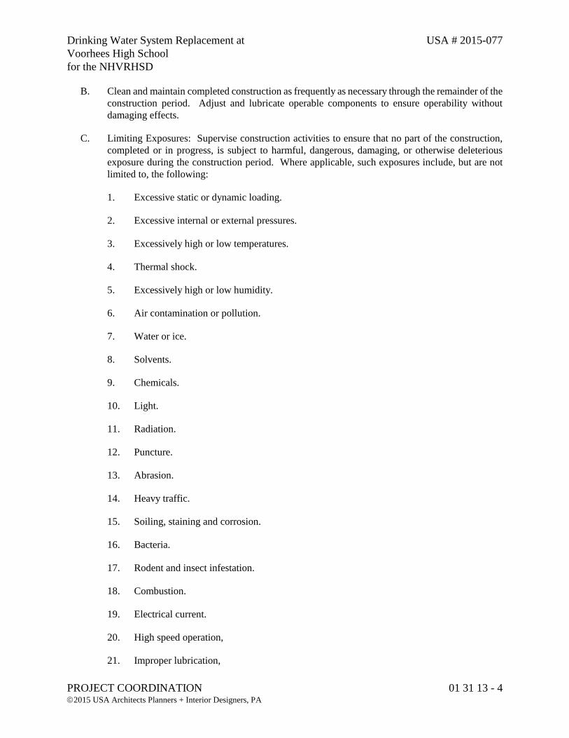
Drinking Water System Replacement at USA # 2015-077
Voorhees High School
for the NHVRHSD
PROJECT COORDINATION 01 31 13 - 4 2015 USA Architects Planners + Interior Designers, PA
B. Clean and maintain completed construction as frequently as necessary through the remainder of the
construction period. Adjust and lubricate operable components to ensure operability without
damaging effects.
C. Limiting Exposures: Supervise construction activities to ensure that no part of the construction,
completed or in progress, is subject to harmful, dangerous, damaging, or otherwise deleterious
exposure during the construction period. Where applicable, such exposures include, but are not
limited to, the following:
1. Excessive static or dynamic loading.
2. Excessive internal or external pressures.
3. Excessively high or low temperatures.
4. Thermal shock.
5. Excessively high or low humidity.
6. Air contamination or pollution.
7. Water or ice.
8. Solvents.
9. Chemicals.
10. Light.
11. Radiation.
12. Puncture.
13. Abrasion.
14. Heavy traffic.
15. Soiling, staining and corrosion.
16. Bacteria.
17. Rodent and insect infestation.
18. Combustion.
19. Electrical current.
20. High speed operation,
21. Improper lubrication,
Drinking Water System Replacement at USA # 2015-077
Voorhees High School
for the NHVRHSD
PROJECT COORDINATION 01 31 13 - 5 2015 USA Architects Planners + Interior Designers, PA
22. Unusual wear or other misuse.
23. Contact between incompatible materials.
24. Destructive testing.
25. Misalignment.
26. Excessive weathering.
27. Unprotected storage.
28. Improper shipping or handling.
29. Theft.
30. Vandalism.
END OF SECTION 01 31 13

Drinking Water System Replacement at USA # 2015-077
Voorhees High School
for the NHVRHSD
SUBMITTALS 01 33 00 - 1 2015 USA Architects Planners + Interior Designers, PA
SECTION 01 33 00 - SUBMITTALS
PART 1 - GENERAL
1.1 RELATED DOCUMENTS
A. Drawings and general provisions of Contract, including General and Supplementary Conditions and
other Division 01 Specification Sections, apply to this Section.
1.2 SUMMARY
A. This Section specifies administrative and procedural requirements for submittals required for
performance of the Work, including;
a. Each Prime Contractor's construction schedule.
b. The Overall Project Schedule.
c. Submittal schedule.
d. Daily construction reports.
e. Shop Drawings.
f. Product Data and Samples.
B. Administrative Submittals: Refer to other Division-1 Sections and other Contract Documents for
requirements for administrative submittals. Such submittals include, but are not limited to:
a. Permits.
b. Applications for payment.
c. Performance and payment bonds.
d. Insurance certificates.
e. List of Subcontractors.
C. The Schedule of Values submittal is included in Section "Applications for Payment."
D. Inspection and test reports are included in Section "Quality Control Services."
1.3 SUBMITTAL PROCEDURES
A. Shop drawings, product data and samples will not be processed by Architect until list of
subcontractors, material suppliers and fabricators is submitted as required by General and
Supplementary Conditions.
B. Coordination: Coordinate preparation and processing of submittals with performance of
construction activities. Transmit each submittal sufficiently in advance of performance of related
construction activities to avoid delay.
1. Coordinate each submittal with fabrication, purchasing, testing, delivery, other submittals and
related activities that require sequential activity.
Drinking Water System Replacement at USA # 2015-077
Voorhees High School
for the NHVRHSD
SUBMITTALS 01 33 00 - 2 2015 USA Architects Planners + Interior Designers, PA
2. Coordinate transmittal of different types of submittals for related elements of the Work so
processing will not be delayed by the need to review submittals concurrently for coordination.
a. The Architect reserves the right to withhold action on a submittal requiring
coordination with other submittals until related submittals are received.
3. Processing: Allow sufficient review time so that installation will not be delayed as a result of
the time required to process submittals, including time for re-submittals.
a. Allow two weeks for initial review. Allow additional time if processing must be
delayed to permit coordination with subsequent submittals. The Architect will
promptly advise the Contractor when a submittal being processed must be delayed for
coordination.
b. If an intermediate submittal is necessary, process the same as the initial submittal.
c. Allow two weeks for reprocessing each submittal.
d. No extension of Contract Time will be authorized because of failure to transmit
submittals to the Architect sufficiently in advance of the Work to permit processing.
C. Submittal Preparation: Place a permanent label or title block on each submittal for identification.
Indicate the name of the entity that prepared each submittal on the label or title block.
1. Provide a space approximately 4" x 5" on the label or beside the title block on Shop Drawings
to record the Contractor's review and approval markings and the action taken.
2. Include the following information on the label for processing and recording action taken.
a. Project name.
b. Date.
c. Name and address of Architect.
d. Name and address of Contractor.
e. Name and address of subcontractor.
f. Name and address of supplier.
g. Name of manufacturer.
h. Number and title of appropriate Specification Section.
i. Drawing number and detail references, as appropriate.
D. Submittal Transmittal: Package each submittal appropriately for transmittal and handling. Transmit
each submittal from Contractor to Architect using a transmittal form. Submittals received from
sources other than the Contractor will be returned without action.
1. On the transmittal Record relevant information and requests for data. On the form, or
separate sheet, record deviations from Contract Document requirements, including minor
variations and limitations. Include Contractor's certification that information complies with
Contract Document requirements.
E. Contractor is responsible for all printing and distribution to all interested Contractors, subcontractors
and suppliers. After Architect's review, prints bearing Architect's review stamp shall be forwarded
by Contractor directly to Owner, Owner's Representative and Contractor's Superintendent at site.
Contractor shall forward additional approved copies to all interested Contractors, subcontractors and
suppliers on project.
Drinking Water System Replacement at USA # 2015-077
Voorhees High School
for the NHVRHSD
SUBMITTALS 01 33 00 - 3 2015 USA Architects Planners + Interior Designers, PA
F. All shop drawings, samples and/or material or equipment submittals shall bear the Contractor's
stamp or seal stating that the Contractor has reviewed the submittals and they conform to the
requirements of the Contract Documents.
1. By submitting shop drawings, product data, samples, and similar submittals, the Contractor
represents that he has determined and verified:
a. Dimensions, quantities, field dimensions, and relationship to existing Work.
b. Coordination with Work to be installed later.
c. Work on shop drawings is accurate and clearly shown.
d. Work equipment will fit into assigned spaces with sufficient access for servicing and
maintenance.
e. Coordination with information on previously accepted shop drawings, product data,
samples, or similar submittals.
f. Full compliance with requirements of Contract Documents.
2. In reviewing shop drawings, product data, samples and similar submittals, the
Architect/Engineer shall be entitled to rely upon the Contractor's representation that
information in submittals is correct and accurate.
3. Submittals that are returned or rejected because of insufficient Contractor review or
coordination shall not be justification for a claim for an extension of time.
1.4 CONTRACTOR'S CONSTRUCTION SCHEDULE
A. Bar-Chart Schedule: Each prime contractor shall prepare a fully developed, horizontal bar-chart type
Contractor's construction schedule, and submit same to the General Contractor within 10 days of the
date established for "Commencement of the Work". The General Contractor/Project Coordinator
will appropriately adjust each primes schedule to incorporate it into the Overall Project Construction
Schedule as indicated below:
a. Provide a separate time bar for each significant construction activity. Provide a
continuous vertical line to identify the first working day of each week. Use the same
breakdown of units of the Work as indicated in the "Schedule of Values".
b. Within each time bar indicate estimated completion percentage in 10 percent
increments. As Work progresses, place a contrasting mark in each bar to indicate
Actual Completion.
c. Prepare the schedule on a sheet, or series of sheets, of stable transparency, or other
reproducible media, of sufficient width to show data for the entire construction period.
d. Secure time commitments for performing critical elements of the Work from parties
involved. Coordinate each element on the schedule with other construction activities;
include minor elements involved in the sequence of the Work. Show each activity in
proper sequence. Indicate graphically sequences necessary for completion of related
portions of the Work.
e. Coordinate the Contractor's construction schedule with the schedule of values, list of
subcontracts, submittal schedule, progress reports, payment requests and other
schedules.
f. Indicate completion in advance of the date established for Substantial Completion.
Indicate Substantial Completion on the schedule to allow time for the Architect's
procedures necessary for certification of Substantial Completion.
Drinking Water System Replacement at USA # 2015-077
Voorhees High School
for the NHVRHSD
SUBMITTALS 01 33 00 - 4 2015 USA Architects Planners + Interior Designers, PA
B. Phasing: Provide notations on the schedule to show how the sequence of the Work is affected by
requirements for phased completion to permit Work by separate Contractors and partial occupancy
by the Owner prior to Substantial Completion.
C. Work Stages: Indicate important stages of construction for each major portion of the Work,
including testing and installation.
D. Area Separations: Provide a separate time bar to identify each major construction area for each
major portion of the Work. Indicate where each element in an area must be sequenced or integrated
with other activities.
E. Distribution: Following response to the initial submittal, print and distribute copies to the Architect,
Owner, subcontractors, and other parties required to comply with scheduled dates. Post copies in the
Project meeting room and temporary field office.
F. Schedule Updating: Revise the schedule after each meeting or activity, where revisions have been
recognized or made. Issue the updated schedule concurrently with report of each meeting.
1.5 SUBMITTAL SCHEDULE
A. After development and acceptance of the Contractor's construction schedule and the Overall Project
Schedule, prepare a complete schedule of submittals. Submit the schedule within the days outlined
in “Section 01 11 05 - Time of Completion” required for establishment of the Contractor's
construction schedule. All submittals shall be made within the days outlined in “Section 01 11 05 -
Time of Completion”.
1. Coordinate submittal schedule with the list of subcontracts, schedule of values and the list of
products as well as the Contractor's construction schedule.
2. Prepare the schedule in chronological order; include submittals required during the first 90
days of construction. Provide the following information:
a. Scheduled date for the first submittal.
b. Related Section number.
c. Submittal category.
d. Name of subcontractor.
e. Description of the part of the Work covered.
B. Distribution: Following response to initial submittal, print and distribute copies to the Architect,
Owner, subcontractors, and other parties required to comply with submittal dates indicated. Post
copies in the Project meeting room and field office.
C. Schedule Updating: Revise the schedule after each meeting or activity, where revisions have been
recognized or made. Issue the updated schedule concurrently with report of each meeting.
Drinking Water System Replacement at USA # 2015-077
Voorhees High School
for the NHVRHSD
SUBMITTALS 01 33 00 - 5 2015 USA Architects Planners + Interior Designers, PA
1.6 DAILY CONSTRUCTION REPORTS
A. Prepare a daily construction report, recording the following information concerning events at the site;
and submit duplicate copies to the Architect at weekly intervals:
a. List of subcontractors at the site.
b. Approximate count of personnel at the site.
c. High and low temperatures, general weather conditions.
d. Accidents and unusual events.
e. Meetings and significant decisions.
f. Stoppages, delays, shortages, losses.
g. Meter readings and similar recordings.
h. Emergency procedures.
i. Orders and requests of governing authorities.
j. Change Orders received, implemented.
k. Services connected, disconnected.
l. Equipment or system tests and start-ups.
m. Partial Completions, occupancies.
n. Substantial Completions authorized.
1.7 SHOP DRAWINGS
A. Submit newly prepared information, drawn to accurate scale. Highlight, encircle, or otherwise
indicate deviations from the Contract Documents. Do not reproduce Contract Documents or copy
standard information as the basis of Shop Drawings. Standard information prepared without specific
reference to the Project is not considered Shop Drawings.
B. Shop Drawings include fabrication and installation drawings, setting diagrams, schedules, patterns,
templates and similar drawings. Include the following information:
a. Dimensions.
b. Identification of products and materials included.
c. Compliance with specified standards.
d. Notation of coordination requirements.
e. Notation of dimensions established by field measurement.
f. Sheet Size: Except for templates, patterns and similar full- size Drawings, submit
Shop Drawings on sheets at least 8-1/2" x 11" but no larger than 36" x 48".
g. Initial Submittal: Submit six (6) blue- or black-line prints for the Architect's review;
all but one print will be returned.
1) One of the prints returned shall be marked-up and maintained as a "Record
Document".
h. Do not use Shop Drawings without an appropriate final stamp indicating action taken
in connection with construction.
C. Coordination drawings are a special type of Shop Drawing that show the relationship and integration
of different construction elements that require careful coordination during fabrication or installation
to fit in the space provided or function as intended.
1. Preparation of coordination Drawings is specified in section "Project Coordination" and may
include components previously shown in detail on Shop Drawings or Product Data.
Drinking Water System Replacement at USA # 2015-077
Voorhees High School
for the NHVRHSD
SUBMITTALS 01 33 00 - 6 2015 USA Architects Planners + Interior Designers, PA
2. Submit coordination Drawings for integration of different construction elements. Show
sequences and relationships of separate components to avoid conflicts in use of space.
1.8 PRODUCT DATA
A. Collect Product Data into a single submittal for each element of construction or system. Product
Data includes printed information such as manufacturer's installation instructions, catalog cuts,
standard color charts, roughing-in diagrams and templates, standard wiring diagrams and
performance curves. Where Product Data must be specially prepared because standard printed data
is not suitable for use, submit as "Shop Drawings."
1. Mark each copy to show applicable choices and options. Where printed Product Data
includes information on several products, some of which are not required, mark copies to
indicate the applicable information. Include the following information:
a. Manufacturer's printed recommendations.
b. Compliance with recognized trade association standards.
c. Compliance with recognized testing agency standards.
d. Application of testing agency labels and seals.
e. Notation of dimensions verified by field measurement.
f. Notation of coordination requirements.
2. Do not submit Product Data until compliance with requirements of the Contract Documents
has been confirmed.
3. Submittals: Submit six (6) copies of each required submittal; The Architect or Engineer will
retain one, and will return the others marked with action taken and corrections or
modifications required.
a. Unless noncompliance with Contract Document provisions is observed, the submittal
may serve as the final submittal.
4. Distribution: Furnish copies of final submittal to installers, subcontractors, suppliers,
manufacturers, fabricators, and others required for performance of construction activities.
Show distribution on transmittal forms.
a. Do not proceed with installation until an applicable copy of Product Data applicable is
in the installer's possession.
b. Do not permit use of unmarked copies of Product Data in connection with
construction.
1.9 SAMPLES
A. Submit full-size, fully fabricated Samples cured and finished as specified and physically identical
with the material or product proposed. Samples include partial sections of manufactured or
fabricated components, cuts or containers of materials, color range sets, and swatches showing color,
texture and pattern.
1. Mount, display, or package Samples in the manner specified to facilitate review of qualities
indicated. Include the following:
Drinking Water System Replacement at USA # 2015-077
Voorhees High School
for the NHVRHSD
SUBMITTALS 01 33 00 - 7 2015 USA Architects Planners + Interior Designers, PA
a. Generic description of the Sample.
b. Sample source.
c. Product name or name of manufacturer.
d. Compliance with recognized standards.
e. Availability and delivery time.
2. Submit Samples for review of kind, color, pattern, and texture, for a final check of these
characteristics with other elements, and for a comparison of these characteristics between the
final submittal and the actual component as delivered and installed.
a. Where variation in color, pattern, texture or other characteristics are inherent in the
material or product represented, submit multiple units (not less than 3), that show
approximate limits of the variations.
b. Refer to other Specification Sections for requirements for Samples that illustrate
workmanship, fabrication techniques, details of assembly, connections, operation and
similar construction characteristics.
3. Preliminary submittals: Where Samples are for selection of color, pattern, texture or similar
characteristics from a range of standard choices, submit a full set of choices for the material or
product.
a. Preliminary submittals will be reviewed and returned with the Architect's mark
indicating selection and other action.
4. Submittals: Except for Samples illustrating assembly details, workmanship, fabrication
techniques, connections, operation and similar characteristics, submit 3 sets; one will be
returned marked with the action taken.
5. Maintain sets of Samples, as returned, at the Project site, for quality comparisons throughout
the course of construction.
a. Unless noncompliance with Contract Document provisions is observed, the submittal
may serve as the final submittal.
b. Sample sets may be used to obtain final acceptance of the construction associated with
each set.
B. Distribution of Samples: Prepare and distribute additional sets to subcontractors, manufacturers,
fabricators, suppliers, installers, and others as required for performance of the Work. Show
distribution on transmittal forms.
1. Field Samples specified in individual Sections are special types of Samples. Field Samples
are full-size examples erected on site to illustrate finishes, coatings, or finish materials and to
establish the standard by which the Work will be judged.
a. Comply with submittal requirements to the fullest extent possible. Process transmittal
forms to provide a record of activity.
1.10 ARCHITECT'S ACTION
A. Except for submittals for record, information or similar purposes, where action and return is required
or requested, the Architect will review each submittal, mark to indicate action taken, and return
promptly.
Drinking Water System Replacement at USA # 2015-077
Voorhees High School
for the NHVRHSD
SUBMITTALS 01 33 00 - 8 2015 USA Architects Planners + Interior Designers, PA
1. Compliance with specified characteristics is the Contractor's responsibility.
B. Action Stamp: The Architect will stamp each submittal with a uniform, self-explanatory action
stamp.
C. Unsolicited Submittals: Unsolicited Submittals and Submittals not required by the Contract
Documents may not be reviewed, may be discarded or returned to the sender without action.
D. Repetitive Submittals: The Architect will take appropriate action TWICE (2) times, for each item
submitted. Submittals requiring more than two (2) reviews due to inadequate or incomplete
information, shall be subject to a review fee for each subsequent submittal. This fee shall be based
upon the hourly rate of the Architect, charged to the Owner, and deducted from the Contract amount.
PART 2 - PRODUCTS (Not Applicable).
PART 3 - EXECUTION (Not Applicable).
END OF SECTION 01 33 00
Drinking Water System Replacement at USA # 2015-077
Voorhees High School
for the NHVRHSD
QUALITY CONTROL SERVICES 01 40 00 - 1 2015 USA Architects Planners + Interior Designers, PA
SECTION 01 40 00- QUALITY CONTROL SERVICES
PART 1 - GENERAL
1.1 RELATED DOCUMENTS
A. Drawings and general provisions of the Contract, including General and Supplementary Conditions
and other Division 01 Specification Sections, apply to this Section.
1.2 SUMMARY
A. This Section specifies administrative and procedural requirements for quality control services.
B. Quality control services include inspections and tests and related actions including reports,
performed by independent agencies, governing authorities, and the Contractor. They do not include
Contract enforcement activities performed by the Architect.
C. Inspection and testing services are required to verify compliance with requirements specified or
indicated. These services do not relieve the Contractor of responsibility for compliance with
Contract Document requirements.
D. Requirements of this Section relate to customized fabrication and installation procedures, not
production of standard products.
1. Specific quality control requirements for individual construction activities are specified in the
Sections that specify those activities. Those requirements, including inspections and tests,
cover production of standard products as well as customized fabrication and installation
procedures.
2. Inspections, test and related actions specified are not intended to limit the Contractor's quality
control procedures that facilitate compliance with Contract Document requirements.
3. Requirements for the Contractor to provide quality control services required by the Architect,
Owner, or authorities having jurisdiction are not limited by provisions of this Section.
1.3 RESPONSIBILITIES
A. Contractor Responsibilities: The Contractor shall provide inspections, tests and similar quality
control services, specified in individual Specification Sections and required by governing authorities,
except where they are specifically indicated to be the Owner's responsibility, or are provided by
another identified entity; these services include those specified to be performed by an independent
agency and not by the Contractor. Costs for these services shall be included in the Contract Sum.
1. The Contractor shall employ and pay an independent agency, to perform specified quality
control services.
Drinking Water System Replacement at USA # 2015-077
Voorhees High School
for the NHVRHSD
QUALITY CONTROL SERVICES 01 40 00 - 2 2015 USA Architects Planners + Interior Designers, PA
a. Where the Owner has engaged a testing agency or other entity for testing and
inspection of a part of the Work, and the Contractor is also required to engage an entity
for the same or related element, the Contractor shall not employ the entity engaged by
the Owner, unless otherwise agreed in writing with the Owner.
2. Retesting: The Contractor is responsible for retesting where results of required inspections,
tests or similar services prove unsatisfactory and do not indicate compliance with Contract
Document requirements, regardless of whether the original test was the Contractor's
responsibility.
a. Cost of retesting construction revised or replaced by the Contractor is the Contractor's
responsibility.
3. Associated Services: The Contractor shall cooperate with agencies performing required
inspections, tests and similar services and provide reasonable auxiliary services as requested.
Notify the agency sufficiently in advance of operations to permit assignment of personnel.
Auxiliary services required include but are not limited to:
a. Providing access to the Work and furnishing incidental labor and facilities necessary to
facilitate inspections and tests.
b. Taking adequate quantities of representative samples of materials that require testing or
assisting the agency in taking samples.
c. Providing facilities for storage and curing of test samples, and delivery of samples to
testing laboratories.
d. Security and protection of samples and test equipment at the Project site.
B. Duties of the Testing Agency: The independent testing agency engaged to perform inspections,
sampling and testing of materials and construction specified in individual Specification Sections
shall cooperate with the Architect and Contractor in performance of its duties, and shall provide
qualified personnel to perform required inspections and tests.
a. The agency shall notify the Architect and Contractor promptly of irregularities or
deficiencies observed in the Work during performance of its services.
b. The agency is not authorized to release, revoke, alter or enlarge requirements of the
Contract Documents, or approve or accept any portion of the Work.
c. The agency shall not perform any duties of the Contractor.
C. Coordination: The Contractor and each agency engaged to perform inspections, tests and similar
services shall coordinate the sequence of activities to accommodate required services with a
minimum of delay. In addition the Contractor and each agency shall coordinate activities to avoid
the necessity of removing and replacing construction to accommodate inspections and tests.
1. The Contractor is responsible for scheduling times for inspections, tests, taking samples and
similar activities.
1.4 SUBMITTALS
A. The independent testing agency shall submit a certified written report of each inspection, test or
similar service, to the Architect, in duplicate, unless the Contractor is responsible for the service. If
the Contractor is responsible for the service, submit a certified written report of each inspection, test
or similar service through the Contractor, in duplicate.
Drinking Water System Replacement at USA # 2015-077
Voorhees High School
for the NHVRHSD
QUALITY CONTROL SERVICES 01 40 00 - 3 2015 USA Architects Planners + Interior Designers, PA
1. Submit additional copies of each written report directly to the governing authority, when the
authority so directs.
2. Report Data: Written reports of each inspection, test or similar service shall include, but not
be limited to:
a. Date of issue.
b. Project title and number.
c. Name, address and telephone number of testing agency.
d. Dates and locations of samples and tests or inspections.
e. Names of individuals making the inspection or test.
f. Designation of the Work and test method.
g. Identification of product and Specification Section.
h. Complete inspection or test data.
i. Test results and an interpretation of test results.
j. Location of sample or test in project.
k. Ambient conditions at the time of sample-taking and testing.
l. Professional opinion as to whether Work complies with Contract Documents
requirements.
m. Name and signature of laboratory inspector.
n. Recommendations on retesting.
1.5 QUALITY ASSURANCE
A. Qualification for Service Agencies: Engage inspection and testing service agencies, including
independent testing laboratories, which are prequalified as complying with "Recommended
Requirements for Independent Laboratory Qualification" by the American Council of Independent
Laboratories, and which specialize in the types of inspections and tests to be performed.
1. Each independent inspection and testing agency engaged on the Project shall be authorized by
authorities having jurisdiction to operate in the State in which the Project is located.
1.6 TRADESMEN & WORKMANSHIP
A. Ensure that tradesmen performing work at site are skilled and knowledgeable in methods
and craftsmanship needed to produce required quality levels for workmanship in completed
work. Remove and replace work which does not comply with workmanship standards as
specified and as recognized in the construction industry for applications indicated. Remove
and replace other work damaged or deteriorated by faulty workmanship or its replacement.
PART 2 - PRODUCTS (Not Applicable).
Drinking Water System Replacement at USA # 2015-077
Voorhees High School
for the NHVRHSD
QUALITY CONTROL SERVICES 01 40 00 - 4 2015 USA Architects Planners + Interior Designers, PA
PART 3 - EXECUTION
3.1 REPAIR AND PROTECTION
A. General: Upon completion of inspection, testing, sample-taking and similar services, repair damaged
construction and restore substrates and finishes to eliminate deficiencies, including deficiencies in
visual qualities of exposed finishes. Comply with Contract Document requirements for "Cutting and
Patching."
B. Protect construction exposed by or for quality control service activities, and protect repaired
construction.
C. Repair and protection is the Contractor's responsibility, regardless of the assignment of responsibility
for inspection, testing or similar services.
3.2 REPLACEMENT OF WORK
A. Within 24 hours after rejection of work pursuant to the General Conditions, remove all materials and
equipment so rejected and immediately replace work, at the Contractor's cost, to the satisfaction of
the Architect. Should the work of the Owner or other Contractors be damaged by such removal or
replacement, the Contractor shall reimburse the Owner or other Contractors for all costs incurred for
correcting damage.
END OF SECTION 01 40 00
Drinking Water System Replacement at USA # 2015-077
Voorhees High School
for the NHVRHSD
REFERENCE STANDARDS AND DEFINITIONS 01 42 19 - 1 2015 USA Architects Planners + Interior Designers, PA
SECTION 01 42 19 - REFERENCE STANDARDS AND DEFINITIONS
PART 1 - GENERAL
1.1 RELATED DOCUMENTS
A. Drawings and general provisions of the Contract, including General and Supplementary Conditions
and other Division 01 Specification Sections, apply to this Section.
1.2 DEFINITIONS
A. General: Basic Contract definitions are included in the Conditions of the Contract.
B. Indicated: The term "indicated" refers to graphic representations, notes or schedules on the
Drawings, or other Paragraphs or Schedules in the Specifications, and similar requirements in the
Contract Documents. Where terms such as "shown," "noted," "scheduled," and "specified" are
used, it is to help the reader locate the reference; no limitation on location is intended.
C. Directed: Terms such as "directed," "requested," "authorized," "selected," "approved," "required,"
and "permitted" mean "directed by the Architect," "requested by the Architect," and similar
phrases.
D. Approve: The term "approved," where used in conjunction with the Architect's action on the
Contractor's submittals, applications, and requests, is limited to the Architect's duties and
responsibilities as stated in the Conditions of the Contract.
E. Regulation: The term "Regulations" includes laws, ordinances, statutes, and lawful orders issued
by authorities having jurisdiction, as well as rules, conventions, and agreements within the
construction industry that control performance of the Work.
F. Furnish: The term "furnish" is used to mean "supply and deliver to the Project site, ready for
unloading, unpacking, assembly, installation, and similar operations."
G. Install: The term "install" is used to describe operations at project site including the actual
"unloading, unpacking, assembly, erection, placing, anchoring, applying, working to dimension,
finishing, curing, protecting, cleaning, and similar operations."
H. Provide: The term "provide" means "to furnish and install, complete and ready for the intended
use."
I. Installer: An "Installer" is the Contractor or an entity engaged by the Contractor, either as an
employee, subcontractor, or contractor of lower tier for performance of a particular construction
activity, including installation, erection, application, and similar operations. Installers are required
to be experienced in the operations they are engaged to perform.
Drinking Water System Replacement at USA # 2015-077
Voorhees High School
for the NHVRHSD
REFERENCE STANDARDS AND DEFINITIONS 01 42 19 - 2 2015 USA Architects Planners + Interior Designers, PA
1. The term "experienced," when used with the term "Installer," means having a minimum of
five previous projects similar in size and scope to this Project, being familiar with the
special requirements indicated, and having complied with requirements of the authority
having jurisdiction.
2. Trades: Use of titles such as "carpentry" is not intended to imply that certain construction
activities must be performed by accredited or unionized individuals of a corresponding
generic name, such as "carpenter." It also does not imply that requirements specified apply
exclusively to tradespersons of the corresponding generic name.
3. Assignment of Specialists: Certain Sections of the Specifications require that specific
construction activities shall be performed by specialists who are recognized experts in the
operations to be performed. The specialists must be engaged for those activities, and
assignments are requirements over which the Contractor has no choice or option.
Nevertheless, the ultimate responsibility for fulfilling Contract requirements remains with
the Contractor.
a. This requirement shall not be interpreted to conflict with enforcement of building
codes and similar regulations governing the Work. It is also not intended to interfere
with local trade union jurisdictional settlements and similar conventions.
J. Project Site is the space available to the Contractor for performance of construction activities,
either exclusively or in conjunction with others performing other work as part of the Project. The
extent of the Project Site is shown on the Drawings and may or may not be identical with the
description of the land on which the Project is to be built.
K. Testing Laboratories: A "testing laboratory" is an independent entity engaged to perform specific
inspections or tests, either at the Project Site or elsewhere, and to report on and, if required, to
interpret results of those inspections or tests.
1.3 SPECIFICATION FORMAT AND CONTENT EXPLANATION
A. Specification Format: These Specifications are organized into Divisions and Sections based on the
Construction Specifications Institute's 50 Division format and MASTERFORMAT numbering
system.
B. Specification Content: This Specification uses certain conventions in the use of language and the
intended meaning of certain terms, words, and phrases when used in particular situations or
circumstances. These conventions are explained as follows:
1. Abbreviated Language: Language used in Specifications and other Contract Documents is
the abbreviated type. Words and meanings shall be interpreted as appropriate. Words that
are implied, but not stated shall be interpolated as the sense required. Singular words will
be interpreted as plural and plural words interpreted as singular where applicable and the
context of the Contract Documents so indicates.
2. Imperative and streamlined language is used generally in the Specifications. Requirements
expressed in the imperative mode are to be performed by the Contractor. At certain
Drinking Water System Replacement at USA # 2015-077
Voorhees High School
for the NHVRHSD
REFERENCE STANDARDS AND DEFINITIONS 01 42 19 - 3 2015 USA Architects Planners + Interior Designers, PA
locations in the text, for clarity, subjective language is used to describe responsibilities that
must be fulfilled indirectly by the Contractor, or by others when so noted.
1.4 INDUSTRY STANDARDS
A. Applicability of Standards: Except where the Contract Documents include more stringent
requirements, applicable construction industry standards have the same force and effect as if bound
or copied directly into the Contract Documents to the extent referenced. Such standards are made a
part of the Contract Documents by reference.
B. Publication Dates: Comply with the standard in effect as of the date of the Contract Documents.
C. Copies of Standards: Each entity engaged in construction on the Project is required to be familiar
with industry standards applicable to that entity's construction activity. Copies of applicable
standards are not bound with the Contract Documents.
1. Where copies of standards are needed for performance of a required construction activity,
the Contractor shall obtain copies directly from the publication source.
D. Abbreviations and Names: Trade association names and titles of general standards are frequently
abbreviated. Where such acronyms or abbreviations are used in the Specifications or other
Contract Documents, they mean the recognized name of the trade association, standards generating
organization, authority having jurisdiction, or other entity applicable to the context of the text
provision. Refer to the "Encyclopedia of Associations," published by Gale Research Co., available
in most libraries.
1.5 SUBMISSIONS
A. For the Owner's records, submit copies of permits, licenses, certifications, inspection reports,
releases, jurisdictional settlements, notices, receipts for fee payments, judgments, and similar
documents, correspondence and records established in conjunction with compliance with standards
and regulations bearing upon performance of the work.
PART 2 - PRODUCTS (Not Applicable)
PART 3 - EXECUTION (Not Applicable)
END OF SECTION 01 42 19

Drinking Water System Replacement at USA # 2015-077
Voorhees High School
for the NHVRHSD
TEMPORARY CONSTRUCTION FACILITIES AND CONTROLS 01 50 00 - 1 2015 USA Architects Planners + Interior Designers, PA
SECTION 01 50 00 - TEMPORARY CONSTRUCTION FACILITIES AND CONTROLS
PART 1 - GENERAL
1.1 RELATED DOCUMENTS
A. Drawings and general provisions of the Contract, including General and Supplementary Conditions
and other Division-01 Specification Sections, apply to this Section.
1.2 SUMMARY
A. This Section specifies requirements for temporary services and facilities, including utilities,
construction and support facilities, security and protection.
1. Pay for all fees and permits. Pay all usage costs required for temporary services.
B. Temporary construction and support facilities required include but are not limited to:
a. Field offices and storage sheds.
b. Sanitary facilities, including drinking water.
c. Light and Temporary Heat and Ventilation.
d. Telephone service.
e. Temporary enclosures, including building security.
f. Hoists.
g. Temporary Project identification signs and bulletin boards.
h. Waste disposal services, Rodent and pest control.
i. Construction aids and miscellaneous services and facilities.
C. Security and protection facilities required include but are not limited to:
a. Temporary fire protection.
b. Barricades, warning signs, lights.
c. Environmental protection.
1.3 DIVISION OF RESPONSIBILITIES
A. Each Contractor is responsible for:
a. Installation, operation, maintenance and removal of each temporary service or facility
usually considered as its own normal construction activity, as well as the costs and use
charges associated with each such service or facility.
b. Plug in electric power cords and extension cords, and supplementary plug in task
lighting and special lighting necessary exclusively for its own activities.
c. Field offices, storage sheds and Waste disposal services.
d. Telephone service.
e. Hoisting requirements.
f. Secure lockup of its own tools, materials and equipment.
Drinking Water System Replacement at USA # 2015-077
Voorhees High School
for the NHVRHSD
TEMPORARY CONSTRUCTION FACILITIES AND CONTROLS 01 50 00 - 2 2015 USA Architects Planners + Interior Designers, PA
g. Construction aids and miscellaneous services exclusively for its own work activities.
1.4 USE CHARGES
A. Electric power from the Owner's existing system may be used.
B. Other entities using temporary services and facilities include, but are not limited to:
a. Other non-prime Contractors.
b. The Owner's work forces.
c. The Architect and his consultants.
d. Testing Agencies
e. Personnel of government agencies.
1.5 QUALITY ASSURANCE
A. Regulations: Comply with industry standards and applicable laws and regulations of authorities
having jurisdiction, including but not limited to:
a. Building Code requirements.
b. Health and safety regulations.
c. Utility company regulations.
d. Police, Fire Department and Rescue Squad rules.
e. Environmental protection regulations.
B. Standards: Comply with NFPA Code 241, "Building Construction and Demolition Operations",
ANSI-A10 Series standards for "Safety Requirements for Construction and Demolition", and NECA
Electrical Design Library "Temporary Electrical Facilities."
1. Refer to "Guidelines for Bid Conditions for Temporary Job Utilities and Services", prepared
jointly by AGC and ASC, for industry recommendations.
2. Electrical Service: Comply with NEMA, NECA and UL standards and regulations for
temporary electric service. Install service in compliance with the National Electric Code
(NFPA 70), latest editions.
3. Assigned responsibilities for installation and operation of temporary utilities are not intended
to interfere with the normal application of trade regulations and union jurisdiction.
C. Inspections: Arrange for authorities having jurisdiction to inspect and test each temporary utility
before use. Obtain required certifications and permits.
1.6 PROJECT CONDITIONS
A. Temporary Utilities: Prepare a schedule indicating dates for implementation and termination of each
temporary utility. At the earliest feasible time, when acceptable to the Owner, change over from use
of temporary service to use of the permanent service.
Drinking Water System Replacement at USA # 2015-077
Voorhees High School
for the NHVRHSD
TEMPORARY CONSTRUCTION FACILITIES AND CONTROLS 01 50 00 - 3 2015 USA Architects Planners + Interior Designers, PA
B. Conditions of Use: Keep temporary services and facilities clean and neat in appearance. Operate in
a safe and efficient manner. Take necessary fire prevention measures. Do not overload facilities, or
permit them to interfere with progress. Do not allow hazardous dangerous or unsanitary conditions,
or public nuisances to develop or persist on the site.
PART 2 - PRODUCTS
2.1 MATERIALS
A. General: Provide new materials; if acceptable to the Architect, undamaged previously used materials
in serviceable condition may be used. Provide materials suitable for the use intended.
B. Tarpaulins: Provide waterproof, fire-resistant, UL labeled tarpaulins with flame-spread rating of 15
or less. For temporary enclosures provide translucent nylon reinforced laminated polyethylene or
polyvinyl chloride fire retardant tarpaulins.
C. Water: Provide potable water approved by local health authorities.
2.2 EQUIPMENT
A. General: Provide new equipment; if acceptable to the Architect, undamaged, previously used
equipment in serviceable condition may be used. Provide equipment suitable for use intended.
B. Electrical Outlets: Provide properly configured NEMA polarized outlets to prevent insertion of
110-120 volt plugs into higher voltage outlets. Provide receptacle outlets equipped with
ground-fault circuit interrupters, reset button and pilot light, for connection of power tools and
equipment.
C. Electrical Power Cords: Provide grounded extension cords; use "hard-service" cords where exposed
to abrasion and traffic. Provide waterproof connectors to connect separate lengths of electric cords,
if single lengths will not reach areas where construction activities are in progress.
D. Lamps and Light Fixtures: Provide general service incandescent lamps of wattage required for
adequate illumination. Provide guard cages or tempered glass enclosures, where exposed to
breakage. Provide exterior fixtures where exposed to moisture.
E. Temporary Toilet Units: Provide self-contained single-occupant toilet units of the chemical, aerated
recirculation, or combustion type, properly vented and fully enclosed with a glass fiber reinforced
polyester shell or similar nonabsorbent material.
F. First Aid Supplies: Comply with governing regulations.
G. Fire Extinguishers: Provide hand-carried, portable UL-rated, class "A" fire extinguishers for
temporary offices and similar spaces. In other locations provide hand-carried, portable, UL-rated,
class "ABC" dry chemical extinguishers, or a combination of extinguishers of NFPA recommended
classes for the exposures.
Drinking Water System Replacement at USA # 2015-077
Voorhees High School
for the NHVRHSD
TEMPORARY CONSTRUCTION FACILITIES AND CONTROLS 01 50 00 - 4 2015 USA Architects Planners + Interior Designers, PA
1. Comply with NFPA 10 and 241 for classification, extinguishing agent and size required by
location and class of fire exposure.
PART 3 - EXECUTION
3.1 INSTALLATION
A. Use qualified personnel for installation of temporary facilities. Locate facilities where they will
serve the Project adequately and result in minimum interference with performance of the Work.
Relocate and modify facilities as required.
B. Provide each facility ready for use when needed to avoid delay. Maintain and modify as required.
Do not remove until facilities are no longer needed, or are replaced by authorized use of completed
permanent facilities.
3.2 TEMPORARY CONSTRUCTION AND SUPPORT FACILITIES INSTALLATION
A. Locate field offices, storage sheds, sanitary facilities and other temporary construction and support
facilities for easy access.
1. Maintain temporary construction and support facilities until near Substantial Completion.
Remove prior to Substantial Completion. Personnel remaining after Substantial Completion
will be permitted to use permanent facilities, under conditions acceptable to the Owner.
B. Provide incombustible construction for offices, shops and sheds located within the construction area,
or within 30 feet of building lines. Comply with requirements of NFPA 241.
C. Temporary Enclosures: Provide temporary enclosure for protection of construction in progress and
completed, from exposure, foul weather, other construction operations and similar activities.
1. Install tarpaulins securely, with incombustible wood framing and other materials. Close
openings of 25 square feet or less with plywood or similar materials.
2. Close openings through floor or roof decks and horizontal surfaces with load-bearing
wood-framed construction.
3. Where temporary wood or plywood enclosure exceeds 100 square feet in area, use UL-labeled
fire-retardant treated material for framing and main sheathing.
4. The Contractor shall provide constant protection against rain, wind, storms, frost or heat so as
to maintain the work, materials, apparatus and fixtures free from damage. At the end of each
day's work, cover work likely to be damaged.
5. Wherever a Contractor provides openings through walls or slabs, each location shall be
adequately protected at the end of each working day with temporary enclosures to make these
areas tight. Openings through exterior walls shall be water tight.
Drinking Water System Replacement at USA # 2015-077
Voorhees High School
for the NHVRHSD
TEMPORARY CONSTRUCTION FACILITIES AND CONTROLS 01 50 00 - 5 2015 USA Architects Planners + Interior Designers, PA
D. Temporary Lifts and Hoists: Provide facilities for hoisting materials and employees. Truck cranes
and similar devices used for hoisting materials are considered "tools and equipment" and not
temporary facilities.
1. The Contractor shall provide and operate all hoists and derricks and furnish and erect all
ladders and scaffolding required by him and his subcontractors, constructed to afford proper
protection to craftsmen, their work and other work in progress and previously executed.
Hoists, derricks and other apparatus shall be equipped with safety devices required by law and
shall be so placed as not to interfere with, or damage, any work or property.
E. Collection and Disposal of Waste: Collect waste from construction areas and elsewhere daily.
Comply with requirements of NFPA 241 for removal of combustible waste material and debris.
Enforce requirements strictly. Do not hold materials more than 7 days during normal weather or 3
days when the temperature is expected to rise above 80 deg F (27 deg C). Handle hazardous,
dangerous, or unsanitary waste materials separately from other waste by containerizing properly.
Dispose of material in a lawful manner.
3.3 PROJECT SIGNS
A. Individual advertising signs will not be permitted.
B. Signs needed to direct deliveries will be permitted with the approval of the Owner required before
erection on the site.
3.4 SECURITY AND PROTECTION FACILITIES INSTALLATION
A. Temporary Fire Protection: Install and maintain temporary fire protection facilities of the types
needed to protect against reasonably predictable and controllable fire losses. Comply with NFPA 10
"Standard for Portable Fire Extinguishers," and NFPA 241 "Standard for Safeguarding Construction,
Alterations and Demolition Operations."
1. Locate fire extinguishers where convenient and effective for their intended purpose.
2. Store combustible materials in containers in fire-safe locations.
3. Maintain unobstructed access to fire extinguishers, fire hydrants, temporary fire protection
facilities, stairways and other access routes for fighting fires. Prohibit smoking in hazardous
fire exposure areas.
4. Provide supervision of welding operations, combustion type temporary heating units, and
similar sources of fire ignition.
5. No welding, cutting by torch, or Work utilizing or causing inflammable waste shall be done
unless adequate fire protection is provided and maintained for the duration of the Work in the
area or operations.
Drinking Water System Replacement at USA # 2015-077
Voorhees High School
for the NHVRHSD
TEMPORARY CONSTRUCTION FACILITIES AND CONTROLS 01 50 00 - 6 2015 USA Architects Planners + Interior Designers, PA
6. No fires for any purpose will be permitted on the Project. Remove all refuse from the
Owner's property.
B. Barricades, Warning Signs and Lights: Comply with standards and code requirements for erection
of structurally adequate barricades. Paint with appropriate colors, graphics and warning signs to
inform personnel and the public of the hazard being protected against. Where appropriate and
needed provide lighting, including flashing red or amber lights.
C. The Contractor shall provide barricades, guard lights and other appurtenances in the area of his
operations for the protection of workmen and public as required by applicable regulations, and for
the protection of streets, lighting, hydrants, walks, curbs and adjacent grounds and planting, for the
duration of such operations. He shall bear the costs of damage caused by him, his Subcontractor or
the employees of each. Warning lights shall be blinker type, battery or electrically operated. Open
flame torches are not permitted.
D. Environmental Protection: Provide protection, operate temporary facilities and conduct construction
in ways and by methods that comply with environmental regulations, and minimize the possibility
that air, waterways and subsoil might be contaminated or polluted, or that other undesirable effects
might result. Avoid use of tools and equipment which produce harmful noise. Restrict use of noise
making tools and equipment to hours that will minimize complaints from persons or firms near the
site.
3.5 OPERATION, TERMINATION AND REMOVAL
A. Supervision: Enforce strict discipline in use of temporary facilities. Limit availability of temporary
facilities to essential and intended uses to minimize waste and abuse.
B. Maintenance: Maintain facilities in good operating condition until removal.
C. Termination and Removal: Unless the Architect requests that it be maintained longer, remove each
temporary facility when the need has ended, or replaced by authorized use of a permanent facility, or
no later than Substantial Completion. Complete or, if necessary, restore permanent construction that
may have been delayed because of interference with the temporary facility. Repair damaged Work,
clean exposed surfaces and replace construction that cannot be satisfactorily repaired.
1. Materials and facilities that constitute temporary facilities are property of the Contractor. The
Owner reserves the right to take possession of Project identification signs.
2. If the Contractor fails to carry out his responsibilities in providing temporary utilities, as set
forth above, the Owner reserves the right to take action as he deems proper for the protection
and conduct of the Work and to deduct the cost thereof from the amount due the Contractor.
END OF SECTION 01 50 00
Drinking Water System Replacement at USA # 2015-077
Voorhees High School
for the NHVRHSD
MATERIALS AND EQUIPMENT 01 60 00 - 1 2015 USA Architects Planners + Interior Designers, PA
SECTION 01 60 00 - MATERIALS AND EQUIPMENT
PART 1 - GENERAL
1.1 RELATED DOCUMENTS
A. Drawings and general provisions of the Contract, including General and Supplementary Conditions
and other Division 01 Specification Sections, apply to this Section.
1.2 SUMMARY
A. This Section specifies administrative and procedural requirements governing the Contractor's
selection of products for use in the Project.
B. The Contractor's Construction Schedule and the Schedule of Submittals are included under Division
01 Section, "Submittals."
C. Standards: Refer to Division 01 Section, "Definitions and Standards" for applicability of industry
standards to products specified.
1.3 DEFINITIONS
A. Definitions used in this Article are not intended to change the meaning of other terms used in the
Contract Documents, such as "specialties," "systems," "structure," "finishes," "accessories," and
similar terms. Such terms are self-explanatory and have well recognized meanings in the
construction industry.
1. "Products" are items purchased for incorporation in the Work, whether purchased for the
Project or taken from previously purchased stock. The term "product" includes the terms
"material," "equipment," "system," and terms of similar intent.
a. "Named Products" are items identified by manufacturer's product name, including
make or model designation, indicated in the manufacturer's published product
literature, that is current as of the date of the Contract Documents.
b. "Foreign Products", as distinguished from "domestic products," are items substantially
manufactured (50 percent or more of value) outside of the United States and its
possessions; or produced or supplied by entities substantially owned (more than 50
percent) by persons who are not citizens of nor living within the United States and its
possessions.
2. "Materials" are products that are substantially shaped, cut, worked, mixed, finished, refined or
otherwise fabricated, processed, or installed to form a part of the Work.
3. "Equipment" is a product with operational parts, whether motorized or manually operated,
that requires service connections such as wiring or piping.
Drinking Water System Replacement at USA # 2015-077
Voorhees High School
for the NHVRHSD
MATERIALS AND EQUIPMENT 01 60 00 - 2 2015 USA Architects Planners + Interior Designers, PA
1.4 QUALITY ASSURANCE
A. Source Limitations: To the fullest extent possible, provide products of the same kind, from a single
source.
1. When specified products are available only from sources that do not or cannot produce a
quantity adequate to complete project requirements in a timely manner, consult with the
Architect for a determination of the most important product qualities before proceeding.
Qualities may include attributes relating to visual appearance, strength, durability, or
compatibility. When a determination has been made, select products from sources that
produce products that possess these qualities, to the fullest extent possible.
B. Compatibility of Options: When the Contractor is given the option of selecting between two or more
products for use on the Project, the product selected shall be compatible with products previously
selected, even if previously selected products were also options.
1. Each prime Contractor is responsible for providing products and construction methods that
are compatible with products and construction methods of other prime or separate
Contractors.
2. If a dispute arises between prime Contractors over concurrently selectable, but incompatible
products, the Architect will determine which products shall be retained and which are
incompatible and must be replaced.
C. Foreign Product Limitations: Except under one or more of the following conditions, provide
domestic products, not foreign products, for inclusion in the Work:
1. No available domestic product complies with the Contract Documents.
2. Domestic products that comply with Contract Document are only available at prices or terms
that are substantially higher than foreign products that also comply with the Contract
Documents.
D. Nameplates: Except for required labels and operating data, do not attach or imprint manufacturer's
or producer's nameplates or trademarks on exposed surfaces of products which will be exposed to
view in occupied spaces or on the exterior.
1. Labels: Locate required product labels and stamps on a concealed surface or, where required
for observation after installation, on an accessible surface that is not conspicuous.
2. Equipment Nameplates: Provide a permanent nameplate on each item of service-connected or
power-operated equipment. Locate on an easily accessible surface which is inconspicuous in
occupied spaces. The nameplate shall contain the following information and other essential
operating data:
a. Name of product and manufacturer.
b. Model and serial number.
c. Capacity.
d. Speed.
e. Ratings.
Drinking Water System Replacement at USA # 2015-077
Voorhees High School
for the NHVRHSD
MATERIALS AND EQUIPMENT 01 60 00 - 3 2015 USA Architects Planners + Interior Designers, PA
1.5 PRODUCT DELIVERY, STORAGE, AND HANDLING
A. Deliver, store and handle products in accordance with the manufacturer's recommendations, using
means and methods that will prevent damage, deterioration and loss, including theft.
1. Schedule delivery to minimize long-term storage at the site and to prevent overcrowding of
construction spaces.
2. Coordinate delivery with installation time to ensure minimum holding time for items that are
flammable, hazardous, easily damaged, or sensitive to deterioration, theft and other losses.
3. Deliver products to the site in the manufacturer's original sealed container or other packaging
system, complete with labels and instructions for handling, storing, unpacking, protecting and
installing.
4. Inspect products upon delivery to ensure compliance with the Contract Documents, and to
ensure that products are undamaged and properly protected.
5. Store products at the site in a manner that will facilitate inspection and measurement of
quantity or counting of units.
6. Store heavy materials away from the Project structure in a manner that will not endanger the
supporting construction.
7. Store products subject to damage by the elements above ground, under cover in a weathertight
enclosure, with ventilation adequate to prevent condensation. Maintain temperature and
humidity within range required by manufacturer's instructions.
PART 2 - PRODUCTS
2.1 PRODUCT SELECTION
A. General Product Requirements: Provide products that comply with the Contract Documents, that are
undamaged and, unless otherwise indicated, unused at the time of installation.
1. Provide products complete with all accessories, trim, finish, safety guards and other devices
and details needed for a complete installation and for the intended use and effect.
2. Standard Products: Where available, provide standard products of types that have been
produced and used successfully in similar situations on other projects.
B. Product Selection Procedures: Product selection is governed by the Contract Documents and
governing regulations, not by previous Project experience. Procedures governing product selection
include the following:
1. Proprietary Specification Requirements: Where only a single product or manufacturer is
named, provide the product indicated. No substitutions will be permitted.
Drinking Water System Replacement at USA # 2015-077
Voorhees High School
for the NHVRHSD
MATERIALS AND EQUIPMENT 01 60 00 - 4 2015 USA Architects Planners + Interior Designers, PA
2. Semiproprietary Specification Requirements: Where three (3) or more products or
manufacturers are named, provide one of the products indicated. No substitutions will be
permitted.
a. Where products or manufacturers are specified by name, accompanied by the term "or
equal," or "or approved equal" comply with the Contract Document provisions
concerning "substitutions" to obtain approval for use of an unnamed product.
3. Non-Proprietary Specifications: When the Specifications list products or manufacturers that
are available and may be incorporated in the Work, but do not restrict the Contractor to use of
these products only, the Contractor may propose any available product that complies with
Contract requirements. Comply with Contract Document provisions concerning
"substitutions" to obtain approval for use of an unnamed product.
4. Descriptive Specification Requirements: Where Specifications describe a product or
assembly, listing exact characteristics required, with or without use of a brand or trade name,
provide a product or assembly that provides the characteristics and otherwise complies with
Contract requirements.
5. Performance Specification Requirements: Where Specifications require compliance with
performance requirements, provide products that comply with these requirements, and are
recommended by the manufacturer for the application indicated. General overall performance
of a product is implied where the product is specified for a specific application.
a. Manufacturer's recommendations may be contained in published product literature, or
by the manufacturer's certification of performance.
6. Compliance with Standards, Codes and Regulations: Where the Specifications only require
compliance with an imposed code, standard or regulation, select a product that complies with
the standards, codes or regulations specified.
7. Visual Matching: Where Specifications require matching an established Sample, the
Architect's decision will be final on whether a proposed product matches satisfactorily.
a. Where no product available within the specified category matches satisfactorily and
also complies with other specified requirements, comply with provisions of the
Contract Documents concerning "substitutions" for selection of a matching product in
another product category, or for noncompliance with specified requirements.
8. Visual Selection: Where specified product requirements include the phrase "...as selected
from manufacturer's standard colors, patterns, textures..." or a similar phrase, select a product
and manufacturer that complies with other specified requirements. The Architect will select
the color, pattern and texture from the product line selected.
Drinking Water System Replacement at USA # 2015-077
Voorhees High School
for the NHVRHSD
MATERIALS AND EQUIPMENT 01 60 00 - 5 2015 USA Architects Planners + Interior Designers, PA
PART 3 - EXECUTION
3.1 INSTALLATION OF PRODUCTS:
A. Comply with manufacturer's instructions and recommendations for installation of products in the
applications indicated. Anchor each product securely in place, accurately located and aligned with
other Work.
B. Fiber, plastic, lead plugs and shields and any device using wood screws are not acceptable as
fastening devices to plaster, tile, concrete or masonry. Use expansion bolts or driven devices in solid
construction and toggle bolts in hollow construction.
C. Clean exposed surfaces and protect as necessary to ensure freedom from damage and deterioration at
time of Substantial Completion.
3.2 PROTECTION
A. Each Prime Contractor shall be responsible for proper care and protection, and shall protect and be
responsible for damage to his work or materials from the date of the Contract until final payment is
made and shall make good, without cost to the Owner, all damage or loss that may occur during this
period. All materials which may be affected by the weather shall be covered and protected to keep
them free from damage while they are being transported to and stored on the site. Should any
material be found defective or in any way contrary to the contract, this material, no matter in what
stage of completion, may be rejected by the Architect and shall be removed from the premises at
once.
END OF SECTION 01 60 00

Drinking Water System Replacement at USA # 2015-077
Voorhees High School
for the NHVRHSD
PROJECT CLOSEOUT 01 70 00- 1 2015 USA Architects Planners + Interior Designers, PA
SECTION 01 70 00 - PROJECT CLOSEOUT
PART 1 - GENERAL
1.1 RELATED DOCUMENTS
A. Drawings and general provisions of the Contract, including General and Supplementary Conditions
and other Division 01 Specification Sections, apply to this Section.
1.2 SUMMARY
A. This Section specifies administrative and procedural requirements for project closeout, including but
not limited to:
a. Inspection procedures.
b. Project Record Document and Operating and Maintenance Manual submittal.
c. Submittal of warranties.
d. Final cleaning.
B. Other administrative submittals required for project closeout (Final Payment) are enumerated in the
Division 01 Section, “Applications for Payment.”
C. Closeout requirements for specific construction activities are included in the appropriate Sections in
Divisions 02 through 49.
1.3 SUBSTANTIAL COMPLETION
A. Preliminary Procedures: Before requesting inspection for certification of Substantial Completion,
complete the following. List exceptions in the request.
1. In the Application for Payment that coincides with, or follows, when Substantial Completion
is claimed, show 100 percent completion for the portion of the Work claimed as substantially
complete. Include supporting documentation for completion as indicated in these Contract
Documents and a statement showing an accounting of changes to the Contract Sum.
a. If 100 percent completion cannot be shown, include a list of incomplete items, the
value of incomplete construction, and reasons the Work is not complete.
2. Advise Owner of pending insurance change-over requirements.
3. Submit specific warranties, workmanship bonds, maintenance agreements, final certifications
and similar documents.
4. Obtain and submit releases enabling the Owner unrestricted use of the Work and access to
services and utilities; include occupancy permits, operating certificates and similar releases.
Drinking Water System Replacement at USA # 2015-077
Voorhees High School
for the NHVRHSD
PROJECT CLOSEOUT 01 70 00- 2 2015 USA Architects Planners + Interior Designers, PA
5. Submit record drawings, maintenance manuals, final damage or settlement survey, property
survey, and similar final record information.
6. Deliver tools, spare parts, extra stock, and similar items.
7. Complete final clean up requirements, including touch-up painting. Touch-up and otherwise
repair and restore marred exposed finishes.
B. Inspection Procedures: On receipt of a request for inspection, the Architect will either proceed with
inspection or advise the Contractor of unfilled requirements. The Architect will prepare the
Certificate of Substantial Completion following inspection, or advise the Contractor of construction
that must be completed or corrected before the certificate will be issued.
a. The Architect will repeat inspection when requested and assured that the Work has
been substantially completed.
b. Results of the completed inspection will form the basis of requirements for final
acceptance.
1.4 FINAL ACCEPTANCE
A. Preliminary Procedures: Before requesting final inspection for certification of final acceptance and
final payment, complete the following. List exceptions in the request.
1. Contractors Affidavit of Payments, Debts and Claims. AIA Document G706.
2. Submit Contractors Affidavit of Release of liens AIA DocumentG706A.
3. Submit consent of surety to final payment. AIA Document G707.
4. Submit the final payment request with releases and supporting documentation not previously
submitted and accepted. Include certificates of insurance for products and completed
operations where required.
5. Submit a certified copy of the Architect's final inspection list (punch list) of items to be
completed or corrected, stating that each item has been completed or otherwise resolved for
acceptance, and the list has been endorsed and dated by the Architect.
6. Submit Contractor's statement that his final application, as presented, is the final bill and no
other claims will be presented.
7. Submit a final liquidated damages settlement statement.
8. Submit evidence of final, continuing insurance coverage complying with insurance
requirements.
B. Reinspection Procedure: The Architect will reinspect the Work upon receipt of notice that the Work,
including inspection list items from earlier inspections, has been completed, except items whose
completion has been delayed because of circumstances acceptable to the Architect.
Drinking Water System Replacement at USA # 2015-077
Voorhees High School
for the NHVRHSD
PROJECT CLOSEOUT 01 70 00- 3 2015 USA Architects Planners + Interior Designers, PA
1. Upon completion of reinspection, the Architect will prepare a certificate of final acceptance,
or advise the Contractor of Work that is incomplete or of obligations that have not been
fulfilled but are required for final acceptance.
2. If necessary, reinspection will be repeated, but at the expense of the Contractor who will
reimburse the Owner for these services by the Architect.
1.5 RECORD DOCUMENT SUBMITTALS
A. General: Do not use record documents for construction purposes; protect from deterioration and loss
in a secure, fire-resistive location; provide access to record documents for the Architect's reference
during normal working hours.
B. Record Drawings: Maintain a clean, undamaged set of blue or black line white-prints of Contract
Drawings and Shop Drawings. Mark the set to show the actual installation where the installation
varies substantially from the Work as originally shown. Mark whichever drawing is most capable of
showing conditions fully and accurately; where Shop Drawings are used, record a cross-reference at
the corresponding location on the Contract Drawings. Give particular attention to concealed
elements that would be difficult to measure and record at a later date.
a. Mark record sets with red erasable pencil; use other colors to distinguish between
variations in separate categories of the Work.
b. Mark new information that is important to the Owner, but was not shown on Contract
Drawings or Shop Drawings.
c. Note related Change Order numbers where applicable.
d. Organize record drawing sheets into manageable sets, bind with durable paper cover
sheets, and print suitable titles, dates and other identification on the cover of each set.
C. Record Specifications: Maintain one complete copy of the Project Manual, including addenda, and
one copy of other written construction documents such as Change Orders and modifications issued
in printed form during construction. Mark these documents to show substantial variations in actual
Work performed in comparison with the text of the Specifications and modifications. Give particular
attention to substitutions, selection of options and similar information on elements that are concealed
or cannot otherwise be readily discerned later by direct observation. Note related record drawing
information and Product Data. Upon completion of the Work, submit record Specifications to the
Architect for the Owner's records.
D. Record Product Data: Maintain one copy of each Product Data submittal. Mark these documents to
show significant variations in actual Work performed in comparison with information submitted.
Include variations in products delivered to the site, and from the manufacturer's installation
instructions and recommendations. Give particular attention to concealed products and portions of
the Work which cannot otherwise be readily discerned later by direct observation. Note related
Change Orders and mark-up of record drawings and Specifications. Upon completion of mark-up,
submit complete set of record Product Data to the Architect for the Owner's records.
E. Record Sample Submitted: Immediately prior to the date or dates of Substantial Completion, the
Contractor will meet at the site with the Architect and the Owner's personnel to determine which of
the submitted Samples that have been maintained during progress of the Work are to be transmitted
to the Owner for record purposes. Comply with delivery to the Owner's Sample storage area.
Drinking Water System Replacement at USA # 2015-077
Voorhees High School
for the NHVRHSD
PROJECT CLOSEOUT 01 70 00- 4 2015 USA Architects Planners + Interior Designers, PA
F. Miscellaneous Record Submittals: Refer to other Specification Sections for requirements of
miscellaneous record-keeping and submittals in connection with actual performance of the Work.
Immediately prior to the date or dates of Substantial Completion, complete miscellaneous records
and place in good order, properly identified and bound or filed, ready for continued use and
reference. Submit to the Architect for the Owner's records.
PART 2 - PRODUCTS (Not Applicable)
PART 3 - EXECUTION
3.1 FINAL CLEANING
A. General: General cleaning during construction is required by the General Conditions and included
in Section "Temporary Facilities".
B. Cleaning: Employ experienced workers or professional cleaners for final cleaning. Clean each
surface or unit to the condition expected in a normal, commercial building cleaning and maintenance
program. Comply with manufacturer's instructions.
1. Complete the following cleaning operations before requesting inspection for Certification of
Substantial Completion.
a. Remove labels that are not permanent labels.
b. Clean exposed exterior and interior hard-surfaced finishes to a dust-free condition, free
of stains, films and similar foreign substances. Restore reflective surfaces to their
original reflective condition.
c. Clean the site, of rubbish, litter and other foreign substances. Sweep paved areas
broom clean; remove stains, spills and other foreign deposits. Rake grounds that are
neither paved nor planted, to a smooth even-textured surface.
C. Removal of Protection: Remove temporary protection and facilities installed for protection of the
Work during construction.
D. Compliance: Comply with regulations of authorities having jurisdiction and safety standards for
cleaning. Do not burn waste materials. Do not bury debris or excess materials on the Owner's
property. Do not discharge volatile, harmful or dangerous materials into drainage systems. Remove
waste materials from the site and dispose of in a lawful manner.
1. Where extra materials of value remaining after completion of associated Work have become
the Owner's property, arrange for disposition of these materials as directed.
3.2 WARRANTIES & GUARANTEES
A. In connection with Contractor's correction of warranted work which has failed, remove and replace
other work of project which has been damaged as a result of such failure, or must be removed and
replaced to provide access for correction of warranted work.
Drinking Water System Replacement at USA # 2015-077
Voorhees High School
for the NHVRHSD
PROJECT CLOSEOUT 01 70 00- 5 2015 USA Architects Planners + Interior Designers, PA
B. The Contractor shall provide a written warranty covering all work performed by him for a period of
one year.
END OF SECTION 01 70 00

Drinking Water System Replacement at USA # 2015-077Voorhees High Schoolfor the NHVRHSD
CLEARING SITE AND MOBILIZATION 01 71 13 - 12015 USA Architects Planners + Interior Designers, PA
SECTION 01 71 13 – CLEARING SITE AND MOBILIZATION
PART 1 - GENERAL
1.1 DESCRIPTION
A. This section includes mobilization of all Contractor's equipment, materials, and work force required to perform the work as specified herein within the required completion time; construction and installation of project identification signs; removal and/or resetting of lawn decorations, minor yard structures, or similar obstructions in the site of the work.
B. If there should be no separate items provided for in the Proposal, clearing site shall also include removal and/or resetting and/or replacement of any fences, decorative shrubs, sidewalks, aprons, driveways, curbing, hedges, or trees in the work site. Clearing site shall also include removal of tree stumps, underbrush, clearing of wooded areas as shown on the plans, or any unsuitable or undesirable obstructions in the area of any of the scheduled items of work. Clearing site shall also include the repair and regrading of all driveways to conform to new construction should there be no applicable items in the Proposal. Clearing site shall also include any work not actually listed in the schedule of items in the Proposal, which is required for completion of work as described by the plans and contract documents.
PART 2 - PRODUCTS
2.1 MATERIALS
A. Materials required for work included under clearing site and mobilization shall comply with applicable specifications cited herein.
PART 3 - EXECUTION
3.1 METHODS OF CONSTRUCTION
A. The site of the project shall be cleared within the limits of construction. (Clearing will proceed only as necessary in order to facilitate construction). The ground surface shall be cleared of all trees, brush, weeds, roots, matted leaves, small structures, debris, and other unsuitable matter, except as otherwise hereinafter provided. Tree stumps must be grubbed out within five feet of any proposed structures, including pipes and ducts, or within 3-1/2 feet of any finished pavement grade. In other areas, except proposed medians and sidewalk areas, they may remain extending not more than one foot above the existing ground surface. Trees, shrubs, and other landscape features within the limits of construction which do not interfere with the project and
Drinking Water System Replacement at USA # 2015-077Voorhees High Schoolfor the NHVRHSD
CLEARING SITE AND MOBILIZATION 01 71 13 - 22015 USA Architects Planners + Interior Designers, PA
are shown on the plans or designated by the Engineer for preservation shall not be removed but shall be protected during the progress of the work in a manner satisfactory to the Engineer.
B. Trees with a minimum of a 12" diameter at breast height (DBH) or a tree with recognized ornamental characteristics are defined by the New Jersey Department of Environmental Protection and Energy (NJDEPE) as specimen trees. These trees are to be protected and preserved wherever feasibly possible.
C. The Contractor shall be instructed by the Engineer as to which specimen trees shall be preserved prior to clearing operations. These trees will be clearly marked by placing a florescent band around the tree trunk. Prior to clearing, these trees shall be protected in an approved manner. No construction related activities shall occur within these protected areas. All tree protection measures shall remain in place until rough grading of the site has been completed.
D. In the performance of clearing site, the Contractor shall be responsible for the preservation of all public and private property, existing trees, plants, and other vegetation that are to remain within or adjacent to the road or right-of-way injury thereto. Special attention shall be given to protection of natural vegetation and other existing landscape features and surroundings. At locations adjacent to operations performed by motorized equipment, the Contractor shall erect and maintain 4' high snow fence around all trees and areas containing vegetation which are to be preserved. The Contractor shall repair all injuries to bark, trunk, limbs, and roots or remaining plants by properly dressing, cutting, tracing and painting, using only approved tree surgery methods, tools and materials.
E. The Contractor shall not exceed the limits of construction. If the limits of construction are exceeded the Contractor shall replace and restore any items damaged or disturbed.
F. If a separate item is not provided for the removal and/or relocation of trees, shrubs, fences, and signs, then the Contractor shall be responsible to use reasonable care in removing and storing the item beyond the work limits.
G. When and where any direct or indirect damage or injury is done to public or private property by or on account of any act, omission, neglect or misconduct on the part of the Contractor in the execution of the work, such property shall be restored by the Contractor, at his expense, to a condition equal to that existing before such damage or injury is done, or he shall make good such damage or injury in a manner acceptable to the Engineer and the property owner.
H. Existing structures within the project, which are to be removed by the Contractor, shall be taken down and disposed of as may be specified.
I. Materials accumulated by clearing, grubbing, removal of structures, and cleaning out as above described shall be disposed of by the Contractor at an off-site location as described below, except that materials suitable for backfill shall be used for that purpose if needed. The Division of Waste Management of the N.J.D.E.P. has advised that all solid waste as identified by Regulations N.J.A.C. 7:26-1, et seq., must be dumped in a licensed landfill site approved by
Drinking Water System Replacement at USA # 2015-077Voorhees High Schoolfor the NHVRHSD
CLEARING SITE AND MOBILIZATION 01 71 13 - 32015 USA Architects Planners + Interior Designers, PA
their office. Because of the nature of the material normally generated during this type of construction, the Division of Waste Management will approve temporary landfills, within their jurisdiction, within a municipality for solid waste materials common and normal to this type of construction. In general:
1. Solid Waste Materials, as defined by Division of Waste Management, common to this construction which are normally spoiled include, but are not limited to: large pieces of blacktop, large pieces of concrete, trees, and stumps;
2. Unacceptable Backfill Material; as defined by NJDEP, common to this construction and which are normally spoiled include, but are not limited to: heavy clay soils, organic materials, silts, and large pieces of rock.
J. The Contractor shall be responsible for locating a disposal site for solid waste materials which is in conformance with all Federal, State and local laws and regulations. The disposal site to be used shall be subject to approval of the Engineer and NJDEP division of Waste Management.
K. Construction methods, required for the work included under "Clearing Site" no specifically described, shall comply with the applicable provisions of these specifications, or as directed by the Engineer.
PART 4 - PAYMENT
4.1 QUANTITY AND PAYMENT
A. No separate payment shall be made for this section. The cost shall be included within the various items bid in the Proposal.
END OF SECTION 01 71 13

Drinking Water System Replacement at USA # 2015-077
Voorhees High School
for the NHVRHSD
CUTTING AND PATCHING 01 73 29 - 1 2015 USA Architects Planners + Interior Designers, PA
SECTION 01 73 29 - CUTTING AND PATCHING
PART 1 - GENERAL
1.1 RELATED DOCUMENTS
A. Drawings and general provisions of the Contract, including General and Supplementary Conditions
and other Division 01 Specification Sections, apply to this Section.
1.2 SUMMARY
A. This Section specifies administrative and procedural requirements for cutting and patching.
B. Refer to other Sections for specific requirements and limitations applicable to cutting and patching
individual parts of the Work.
C. Demolition of selected portions of the building for alterations is included in Division 01 Section,
"Selective Demolition."
1.3 SUBMITTALS
A. Cutting and Patching Proposal: Where approval of procedures for cutting and patching is required
before proceeding, submit a proposal describing procedures well in advance of the time cutting and
patching will be performed and request approval to proceed. Include the following information, as
applicable, in the proposal:
1. Describe the extent of cutting and patching required and how it is to be performed; indicate
why it cannot be avoided.
2. Describe anticipated results in terms of changes to existing construction; include changes to
structural elements and operating components as well as changes in the building's appearance
and other significant visual elements.
3. List products to be used and firms or entities that will perform Work.
4. Indicate dates when cutting and patching is to be performed.
5. List utilities that will be disturbed or affected, including those that will be relocated and those
that will be temporarily out-of-service. Indicate how long service will be disrupted.
6. Where cutting and patching involves addition of reinforcement to structural elements, submit
details and engineering calculations to show how reinforcement is integrated with the original
structure.
Drinking Water System Replacement at USA # 2015-077
Voorhees High School
for the NHVRHSD
CUTTING AND PATCHING 01 73 29 - 2 2015 USA Architects Planners + Interior Designers, PA
7. Approval by the Architect to proceed with cutting and patching does not waive the Architect's
right to later require complete removal and replacement of a part of the Work found to be
unsatisfactory.
1.4 QUALITY ASSURANCE
A. Requirements for Structural Work: Do not cut and patch structural elements in a manner that would
reduce their load-carrying capacity or load-deflection ratio.
1. Obtain approval of the cutting and patching proposal before cutting and patching the
following structural elements:
a. Bearing and retaining walls.
b. Structural concrete.
c. Structural steel.
d. Lintels.
e. Timber and primary wood framing.
f. Structural decking.
g. Stair systems.
h. Miscellaneous structural metals.
i. Equipment supports.
j. Piping, ductwork, vessels and equipment.
B. Operational and Safety Limitations: Do not cut and patch operating elements or safety related
components in a manner that would result in reducing their capacity to perform as intended, or result
in increased maintenance, or decreased operational life or safety.
1. Obtain approval of the cutting and patching proposal before cutting and patching the
following operating elements or safety related systems:
a. Primary operational systems and equipment.
b. Air or smoke barriers.
c. Water, moisture, or vapor barriers.
d. Membranes and flashings.
e. Fire protection systems.
f. Noise and vibration control elements and systems.
g. Control systems.
h. Communication systems.
i. Electrical wiring systems.
C. Visual Requirements: Do not cut and patch construction exposed on the exterior or in occupied
spaces, in a manner that would, in the Architect's opinion, reduce the building's aesthetic qualities, or
result in visual evidence of cutting and patching. Remove and replace Work cut and patched in a
visually unsatisfactory manner.
Drinking Water System Replacement at USA # 2015-077
Voorhees High School
for the NHVRHSD
CUTTING AND PATCHING 01 73 29 - 3 2015 USA Architects Planners + Interior Designers, PA
PART 2 - PRODUCTS
2.1 MATERIALS
A. Use materials that are identical to existing materials. If identical materials are not available or cannot
be used where exposed surfaces are involved, use materials that match existing adjacent surfaces to
the fullest extent possible with regard to visual effect. Use materials whose installed performance
will equal or surpass that of existing materials.
PART 3 - EXECUTION
3.1 INSPECTION
A. Before cutting existing surfaces, examine surfaces to be cut and patched and conditions under which
cutting and patching is to be performed. Take corrective action before proceeding, if unsafe or
unsatisfactory conditions are encountered.
1. Before proceeding, meet at the site with parties involved in cutting and patching, including
mechanical and electrical trades. Review areas of potential interference and conflict.
Coordinate procedures and resolve potential conflicts before proceeding.
3.2 PREPARATION
A. Temporary Support: Provide temporary support of Work to be cut.
B. Protection: Protect existing construction during cutting and patching to prevent damage. Provide
protection from adverse weather conditions for portions of the Project that might be exposed during
cutting and patching operations.
C. Avoid interference with use of adjoining areas or interruption of free passage to adjoining areas.
D. Take all precautions necessary to avoid cutting existing pipe, conduit or ductwork serving the
building, but scheduled to be removed or relocated until provisions have been made to bypass them.
3.3 PERFORMANCE
A. General: A Contractor, subcontractor or sub-subcontractor requiring changes in existing work shall
have such changes performed by the trades skilled in performing the particular work and such
changes shall be at the expense of the Contractor, subcontractor or sub-subcontractor requiring the
change. Review changes with the Architect prior to proceeding with the work and include
installation of such reinforcement of the work as the Architect may direct.
B. Employ skilled workmen to perform cutting and patching. Proceed with cutting and patching at the
earliest feasible time and complete without delay.
Drinking Water System Replacement at USA # 2015-077
Voorhees High School
for the NHVRHSD
CUTTING AND PATCHING 01 73 29 - 4 2015 USA Architects Planners + Interior Designers, PA
1. Cut existing construction to provide for installation of other components or performance of
other construction activities and the subsequent fitting and patching required to restore
surfaces to their original condition.
C. Cutting: Cut existing construction using methods least likely to damage elements to be retained or
adjoining construction. Where possible review proposed procedures with the original installer;
comply with the original installer's recommendations.
1. In general, where cutting is required use hand or small power tools designed for sawing or
grinding, not hammering and chopping. Cut holes and slots neatly to size required with
minimum disturbance of adjacent surfaces. Temporarily cover openings when not in use.
D. Patching: Patch with durable seams that are as invisible as possible. Comply with specified
tolerances.
1. Where feasible, inspect and test patched areas to demonstrate integrity of the installation.
2. Restore exposed finishes of patched areas and extend finish restoration into retained adjoining
construction in a manner that will eliminate evidence of patching and refinishing.
3. Firestopping and draftstopping.
a. Where fire rated and/or smoke barrier construction (walls, floors or ceilings) are
penetrated, all penetrations shall be fire-safed and sealed using appropriate fire rated
materials and approved methods.
b. Where non-fire rated construction (walls, floors or ceilings) are penetrated, the
penetration shall be sealed tight with approved draftstopping materials.
3.4 CLEANING
A. Thoroughly clean areas and spaces where cutting and patching is performed or used as access.
Remove completely paint, mortar, oils, putty and items of similar nature. Thoroughly clean piping,
conduit and similar features before painting or other finishing is applied. Restore damaged pipe
covering to its original condition.
END OF SECTION 01 73 29
Drinking Water System Replacement at USA # 2015-077
Voorhees High School
for the NHVRHSD
RESTORATION, CLEAN-UP AND DEMOBILIZATION 01 74 24 - 1 2015 USA Architects Planners + Interior Designers, PA
SECTION 01 74 24 – RESTORATION, CLEAN-UP AND DEMOBILIZATION
PART 1 - GENERAL
1.1 DESCRIPTION
A. Unless otherwise required by the plans, all areas, structures, utilities, line striping, pavement
markings, signs, etc., along the line of the work, which are removed, destroyed, lost, or injured on
account of any act or omission on the part of the Contractor, his agent, servants, or employees in the
prosecution of the work will be restored to their original condition at the expense of the Contractor.
B. On paved surfaces, the Contractor shall not use or operate tractors, bulldozers, or other power-
operated equipment, the treads or wheels of which are so shaped as to cut or otherwise damage such
surfaces.
PART 2 - PRODUCTS (not applicable)
PART 3 - EXECUTION
3.1 METHODS OF CONSTRUCTION
A. At such times as may be directed, all gutters, sidewalks, and lawns, etc. affected by the work done
under the contract shall be restored by the Contractor to the same condition in which they were at the
time of the opening of bids for this contract. Any necessary topsoiling and seeding shall be done
according to the applicable specifications.
B. The Contractor shall enclose the trunks of trees, as directed by the Engineer, with substantial wooden
boxes of such height as is required to protect them from injury from piled material or from
equipment, or from his operations, or otherwise due to his work. Excavation machinery and cranes
shall be handled with care to prevent damage to trees, particularly overhanging branches and limbs.
Precautions taken to protect trees shall be as shown in the details in the plans.
C. Branches, limbs, and roots shall not be cut except by permission of the Engineer. All cutting shall
be smoothly and neatly done without splitting or crushing. In case of cutting or unavoidable damage
to branches, limbs, and trunks of trees, the cut or damaged portions shall be neatly trimmed and
covered with an application of grafting wax or tree healing paint as directed.
Drinking Water System Replacement at USA # 2015-077
Voorhees High School
for the NHVRHSD
RESTORATION, CLEAN-UP AND DEMOBILIZATION 01 74 24 - 2 2015 USA Architects Planners + Interior Designers, PA
3.2 GENERAL CLEAN-UP AND DEMOBILIZATION
A. At such times as may be directed, and upon completion of the work performed under this contract,
the Contractor shall remove from the job site all materials, equipment, laborers, and all else
necessary which were placed thereon by him as a consequence of performing this work and which
are not required by the Contract to be left as part of the finished work. The entire work and portions
of the site affected thereby shall be left in a satisfactory condition.
B. All sidewalks, gutters and crosswalks shall be swept clean of all material which may have
accumulated thereon by reason of the work performed under this Contract, and, if required, they
shall be sprinkled with water during the sweeping.
PART 4 - PAYMENT
4.1 QUANTITY AND PAYMENT
A. No separate payment shall be made for this section. The cost shall be included within the various
items bid in the Proposal.
END OF SECTION 01 74 24
Drinking Water System Replacement at USA # 2015-077 Voorhees High School for the NHVRHSD
UTILITY TEST PITS 02 06 31 - 1 2015 USA Architects Planners + Interior Designers, PA
SECTION 02 06 31 – UTILITY TEST PITS
PART 1 - GENERAL
1.1 DESCRIPTION
A. Utility test pits shall be dug at locations shown on the plans or designated by the Engineer in order to locate underground utilities and/or structures which may be affected by or interfere with the proposed construction.
PART 2 - PRODUCTS (not applicable)
PART 3 - EXECUTION
3.1 METHODS OF CONSTRUCTION
A. The Contractor shall excavate at locations shown on the plans or designated by the Engineer. The Contractor shall excavate to the limits and depths that may be necessary in order to locate underground structures or utilities. It shall be the Contractor's responsibility to measure and record the horizontal and vertical location of all utilities encountered during test pit excavations and submit this information to the Engineer.
B. The Contractor shall notify all appropriate utilities at least 72 hours prior to the start of any construction. All utilities have been identified based on the available information and listed on these plans in accordance with Act 187 requirements. The Contractor shall verify the locations of existing utilities and all efforts shall be undertaken to protect existing utilities and maintain uninterrupted service. Any damage to utilities by the Contractor shall be repaired immediately at the Contractor’s expense. Restoration of all existing surface improvements damaged or altered during construction, including landscaping, shall also be the responsible of the Contractor.
C. All test pits indicated on the plans or ordered by the Engineer shall be dug at least seven (7) days prior to start of construction.
D. The information obtained from the test pits will enable the Engineer to make any necessary adjustments in the design prior to construction in case of conflicts. The Contractor shall make no claim for additional compensation on account of any delays due to these adjustments. Construction shall not begin until the Engineer gives authorization to proceed after all test pits have been excavated and necessary information has been submitted to the Engineer.
E. All provisions of other portions of the specifications, as they relate to the excavation of test pits, shall apply. These shall include, but are not limited to, provisions for cutting and removal of pavements,
Drinking Water System Replacement at USA # 2015-077 Voorhees High School for the NHVRHSD
UTILITY TEST PITS 02 06 31 - 2 2015 USA Architects Planners + Interior Designers, PA
protection of underground utilities, excavation and backfill, dewatering trench, temporary sheeting and bracing and temporary pavement.
PART 4 - PAYMENT
4.1 QUANTITY AND PAYMENT
A. No separate payment shall be made for this section. The cost shall be included within the various items bid in the Proposal.
END OF SECTION 02 06 31
Drinking Water System Replacement at USA # 2015-077
Voorhees High School
for the NHVRHSD
SELECTIVE DEMOLITION 02 41 10 - 1 2015 USA Architects Planners + Interior Designers, PA
SECTION 02 41 10 - SELECTIVE DEMOLITION
PART 1 - GENERAL
1.1 RELATED DOCUMENTS
A. Drawings and general provisions of the Contract, including General and Supplementary Conditions
and Division 01 Specification Sections, apply to this Section.
1.2 SUMMARY
A. This Section includes the following:
1. Demolition and removal of various building elements as indicated on the drawings.
2. Demolition and removal of existing above grade improvements.
3. Demolition and removal of existing below grade improvements.
4. Demolition of all work as may be required to produce a finished product, whether indicated
on the drawings or not.
1.3 DEFINITIONS
A. Remove: Remove and legally dispose of items except those indicated to be reinstalled, salvaged, or
to remain the Owner's property.
B. Existing to Remain: Protect construction indicated to remain against damage and soiling during
selective demolition. When permitted by the A/E, items may be removed to a suitable, protected
storage location during selective demolition and then cleaned and reinstalled in their original
locations.
1.4 QUALITY ASSURANCE
A. Demolition Firm Qualifications: Engage an experienced firm that has successfully completed
selective demolition Work similar to that indicated for this Project.
B. Regulatory Requirements: Comply with governing EPA notification regulations before starting
selective demolition. Comply with hauling and disposal regulations of authorities having
jurisdiction.
Drinking Water System Replacement at USA # 2015-077
Voorhees High School
for the NHVRHSD
SELECTIVE DEMOLITION 02 41 10 - 2 2015 USA Architects Planners + Interior Designers, PA
1.5 PROJECT CONDITIONS
A. Owner will occupy portions of the building immediately adjacent to selective demolition area.
Conduct selective demolition so that Owner's operations will not be disrupted. Provide not less than
72 hours' notice to Owner of activities that will affect Owner's operations.
B. Owner assumes no responsibility for actual condition of buildings to be selectively demolished.
1. Conditions existing at time of inspection for bidding purpose will be maintained by Owner as
far as practical.
C. Asbestos: It is not expected that asbestos will be encountered in the Work. If any materials
suspected of containing asbestos are encountered, do not disturb the materials. Immediately notify
the A/E and the Owner.
D. Storage or sale of removed items or materials on-site will not be permitted.
1.6 SCHEDULING
A. Arrange selective demolition schedule so as not to interfere with Owner's on-site operations.
1.7 WARRANTY
A. Existing Special Warranty: Remove, replace, patch, and repair materials and surfaces cut or
damaged during selective demolition, by methods and with materials so as not to void existing
warranties.
PART 2 - EXECUTION
2.1 EXAMINATION
A. Verify that utilities have been disconnected and capped.
B. Survey existing conditions and correlate with requirements indicated to determine extent of selective
demolition required.
C. When unanticipated mechanical, electrical, or structural elements that conflict with the intended
function or design are encountered, investigate and measure the nature and extent of the conflict.
Promptly submit a written report to the A/E.
D. Survey the condition of the building to determine whether removing any element might result in
structural deficiency or unplanned collapse of any portion of the structure or adjacent structures
during selective demolition.
Drinking Water System Replacement at USA # 2015-077
Voorhees High School
for the NHVRHSD
SELECTIVE DEMOLITION 02 41 10 - 3 2015 USA Architects Planners + Interior Designers, PA
E. Perform surveys as the Work progresses to detect hazards resulting from selective demolition
activities.
2.2 UTILITY SERVICES
A. Maintain existing utilities indicated to remain in service and protect them against damage during
selective demolition operations.
1. Do not interrupt existing utilities serving occupied or operating facilities, except when
authorized in writing by Owner and authorities having jurisdiction. Provide temporary
services during interruptions to existing utilities, as acceptable to Owner and to governing
authorities.
a. Provide not less than 72 hours' notice to Owner if shutdown of service is required
during changeover.
B. Utility Requirements: Locate, identify, disconnect, and seal or cap off indicated utility services
serving building to be selectively demolished.
1. Arrange to shut off indicated utilities with utility companies.
2. Where utility services are required to be removed, relocated, or abandoned, provide bypass
connections to maintain continuity of service to other parts of the building before proceeding
with selective demolition.
3. Cut off pipe or conduit in walls or partitions to be removed. Cap, valve, or plug and seal the
remaining portion of pipe or conduit after bypassing.
C. Utility Requirements: Refer to Authorities Having Jurisdiction (AHJ) for shutting off,
disconnecting, removing, and sealing or capping utility services. Do not start selective demolition
work until utility disconnecting and sealing have been completed and verified in writing.
2.3 PREPARATION
A. Conduct demolition operations and remove debris to ensure minimum interference with roads,
streets, walks, and other adjacent occupied and used facilities.
1. Do not close or obstruct streets, walks, or other adjacent occupied or used facilities without
permission from Owner and authorities having jurisdiction. Provide alternate routes around
closed or obstructed traffic ways if required by governing regulations.
2.4 PROTECTION
A. Existing Facilities: Protect adjacent walkways, loading docks, building entries, and other building
facilities during demolition operations. Maintain exits from existing buildings.
Drinking Water System Replacement at USA # 2015-077
Voorhees High School
for the NHVRHSD
SELECTIVE DEMOLITION 02 41 10 - 4 2015 USA Architects Planners + Interior Designers, PA
B. Temporary Protection: Erect temporary protection, such as walks, fences, railings, canopies, and
covered passageways, where required by authorities having jurisdiction and as indicated. Comply
with requirements in Division 01 Section "Temporary Facilities and Controls."
1. Protect adjacent buildings and facilities from damage due to demolition activities.
2. Protect existing site improvements, appurtenances, and landscaping to remain.
3. Erect a plainly visible fence around drip line of individual trees or around perimeter drip line
of groups of trees to remain.
4. Provide temporary barricades and other protection required to prevent injury to people and
damage to adjacent buildings and facilities to remain.
5. Provide protection to ensure safe passage of people around building demolition area and to
and from occupied portions of adjacent buildings and structures.
6. Protect walls, windows, roofs, and other adjacent exterior construction that are to remain and
that are exposed to building demolition operations.
7. Erect and maintain dustproof partitions and temporary enclosures to limit dust, noise, and dirt
migration to occupied portions of adjacent buildings.
C. Remove temporary barriers and protections where hazards no longer exist. Where open excavations
or other hazardous conditions remain, leave temporary barriers and protections in place.
2.5 POLLUTION CONTROLS
A. Remove and transport debris in a manner that will prevent spillage on adjacent surfaces and areas.
B. Clean adjacent structures and improvements of dust, dirt, and debris caused by selective demolition
operations. Return adjacent areas to condition existing before start of selective demolition.
2.6 SELECTIVE DEMOLITION
A. Demolish and remove existing construction only to the extent required by new construction and as
indicated. Use methods required to complete Work within limitations of governing regulations and
as follows:
1. Proceed with selective demolition systematically, from higher to lower level. Complete
selective demolition work above each floor or tier before disturbing supporting members on
lower levels.
2. Neatly cut openings and holes plumb, square, and true to dimensions required. Use cutting
methods least likely to damage construction to remain or adjoining construction. To minimize
disturbance of adjacent surfaces, use hand or small power tools designed for sawing or
grinding, not hammering and chopping. Temporarily cover openings to remain.
3. Cut or drill from the exposed or finished side into concealed surfaces to avoid marring
existing finished surfaces.
Drinking Water System Replacement at USA # 2015-077
Voorhees High School
for the NHVRHSD
SELECTIVE DEMOLITION 02 41 10 - 5 2015 USA Architects Planners + Interior Designers, PA
4. Remove decayed, vermin-infested, or otherwise dangerous or unsuitable materials and
promptly dispose of off-site.
5. Remove structural framing members and lower to ground by method suitable to avoid free fall
and to prevent ground impact or dust generation.
6. Locate selective demolition equipment throughout the structure and remove debris and
materials so as not to impose excessive loads on supporting walls, floors, or framing.
7. Dispose of demolished items and materials promptly. On-site storage or sale of removed
items is prohibited.
8. Return elements of construction and surfaces to remain to condition existing before start of
selective demolition operations.
2.7 PATCHING AND REPAIRS
A. Promptly patch and repair holes and damaged surfaces caused to adjacent construction by selective
demolition operations.
B. Patching is specified in Division 01 Section "Cutting and Patching."
C. Where repairs to existing surfaces are required, patch to produce surfaces suitable for new materials.
D. Restore exposed finishes of patched areas and extend finish restoration into adjoining construction to
remain in a manner that eliminates evidence of patching and refinishing.
2.8 DISPOSAL OF DEMOLISHED MATERIALS
A. General: Promptly dispose of demolished materials. Do not allow demolished materials to
accumulate on-site.
B. Burning: Do not burn demolished materials.
C. Disposal: Transport demolished materials off Owner's property and legally dispose of them.
END OF SECTION 02 41 10

Drinking Water System Replacement at USA # 2015-077 Voorhees High School for the NHVRHSD
CONCRETE WORK (SITE) 03 11 10 - 1 2015 USA Architects Planners + Interior Designers, PA
SECTION 03 11 10 – CONCRETE WORK (SITE)
PART 1 - GENERAL
1.1 DESCRIPTION
A. The Work within this section includes, but is not limited to, the furnishing of all equipment, labor and materials and performing all operations necessary to complete the concrete work as specified in accordance with the specifications, applicable drawings and Contract Documents.
1.2 QUALITY ASSURANCE
A. Reference standards shall be the following:
1. American Association of State Highway and Transportation Officials (AASHTO).
2. American Concrete Institute (ACI).
3. American Society for Testing and Materials (ASTM).
4. Concrete Reinforcing Steel Institute (CRSI).
5. U.S. Product Standards (PS).
1.3 SUBMITTALS
A. Product Data: Submit data for proprietary materials and items, including reinforcement and forming accessories, admixtures, patching compounds, waterstops, joint systems, curing compounds, dry shake finish materials, and others as requested by Engineer.
B. Shop Drawings: Reinforcement: Submit original shop drawings for fabrication, bending, and placement of concrete reinforcement. Comply with ACI 315 Manual of Standard Practice for Detailing Reinforced Concrete Structures showing bar schedules, stirrup spacing, diagrams of bent bars, and arrangement of concrete reinforcement. Include special reinforcement required for openings through concrete structures.
C. Samples: Submit samples of materials as requested by Engineer including names, sources, and descriptions.
D. Laboratory Test Reports: Submit laboratory test reports for concrete materials and mix design test.
Drinking Water System Replacement at USA # 2015-077 Voorhees High School for the NHVRHSD
CONCRETE WORK (SITE) 03 11 10 - 2 2015 USA Architects Planners + Interior Designers, PA
E. Material Certificates: Provide material certificates in lieu of material laboratory test reports when permitted by Engineer. Materials certificates shall be signed by manufacturer and Contractor certifying that each material item complies with, or exceeds, specified requirements. Provide certification from admixture manufacturers that chloride content complies with specification requirements.
F. Concrete Testing Service: Engage a testing laboratory acceptable to Engineer to perform material evaluation tests.
G. Materials and installed Work may require testing and retesting at anytime during progress of Work. Tests, including retesting of rejected materials for installed Work, shall be done at Contractor's expense.
1.4 PROJECT CONDITIONS
A. Protection of Footings Against Freezing: Cover completed Work at footing level with sufficient temporary or permanent cover as required to protect footings and adjacent subgrade against possibility of freezing; maintain cover for time period as necessary.
B. Protect adjacent finish materials against spatter during concrete placement.
PART 2 - PRODUCTS
2.1 FORM MATERIALS
A. Forms for Exposed Finish Concrete: Plywood, metal, metal framed plywood faced, or other acceptable panel type materials, to provide continuous, straight, smooth, exposed surfaces. Furnish in largest practicable sizes to minimize number of joints and to conform to joint system shown on drawings.
B. Use plywood complying with PS 1, B B (Concrete Form) Plywood, Class I, Exterior Grade or better, mill oiled and edge sealed, with each piece bearing legible inspection trademark.
C. Forms for Unexposed Finish Concrete: Plywood, lumber, metal, or other acceptable material. Provide lumber dressed on at least two edges and one side for tight fit.
D. Form Coatings: Provide commercial formulation form coating compounds that will not bond with, stain, nor adversely affect concrete surfaces, and will not impair subsequent treatments of concrete surfaces.
E. Form Ties: Factory fabricated, adjustable length, removable or snap-off metal form ties, designed to prevent form deflection and to prevent spalling concrete upon removal. Provide units that will leave no metal closer than 1½ inches to surface.
Drinking Water System Replacement at USA # 2015-077 Voorhees High School for the NHVRHSD
CONCRETE WORK (SITE) 03 11 10 - 3 2015 USA Architects Planners + Interior Designers, PA
F. Provide ties that, when removed, will leave holes not larger than 1-inch diameter in concrete surface.
2.2 REINFORCING MATERIALS
A. Reinforcing Bars: ASTM A615, Grade 60, deformed.
B. Welded Wire Fabric: ASTM A185, welded steel wire fabric.
C. Supports for Reinforcement: Bolsters, chairs, spacers, and other devices for spacing, supporting, and fastening reinforcing bars and welded wire fabric in place. Use wire bar type supports complying with CRSI specifications.
D. For slabs on grade, use supports with sand plates or horizontal runners where base material will not support chair legs.
E. For exposed to view concrete surfaces, where legs of supports are in contact with forms, provide supports with legs that are plastic protected (CRSI, Class 1) or stainless steel protected (CRSI, Class 2).
2.3 CONCRETE MATERIALS
A. Portland Cement: ASTM C150, Type I.
B. Use one brand of cement throughout Project, unless otherwise acceptable to Engineer.
C. Normal Weight Aggregates: ASTM C33, and as herein specified. Provide aggregates from a single source for exposed concrete.
D. For exterior exposed surfaces, do not use fine or coarse aggregates containing spalling causing deleterious substances.
E. Water: Potable.
F. Air Entraining Admixture: ASTM C260, certified by manufacturer to be compatible with other required admixtures.
G. Available Products: Subject to compliance with requirements, products that may be incorporated in the Work include, but are not limited to, the following:
1. Air Mix; Euclid Chemical Co.
2. Sika Aer; Sika Corp.
3. MB VR or MB AE; Master Builders
Drinking Water System Replacement at USA # 2015-077 Voorhees High School for the NHVRHSD
CONCRETE WORK (SITE) 03 11 10 - 4 2015 USA Architects Planners + Interior Designers, PA
4. Darex AEA or Daravair; W.R. Grace
5. Edoco 2001 or 2002; Edoco Technical Products
6. Air Tite; Gifford Hill/American Admixtures
H. Water Reducing Admixture: ASTM C494, Type A, and containing not more than 0.1 percent chloride ions.
I. Available Products: Subject to compliance with requirements, products that may be incorporated in the Work include, but are not limited to, the following:
1. WRDA Hycol; W.R. Grace
2. PSI N; Gifford Hill/American Admixtures
3. Eucon WR 75; Euclid Chemical Co.
4. Pozzolith Normal; Master Builders
5. Plastocrete 160; Sika Chemical Corp.
6. Chemtard; Chem Masters Corp.
7. Pro Kete N; Protex Industries, Inc.
J. High Range Water Reducing Admixture (Super Plasticizer): ASTM C494, Type F or Type G and containing not more than 0.1 percent chloride ions.
K. Available Products: Subject to compliance with requirements, products that may be incorporated in the Work include, but are not limited to, the following:
1. WRDA 19 or Daracem; W.R. Grace
2. PSP; Protex Industries Inc.
3. Super P; Anti Hydro
4. Sikament; Sika Chemical Corp.
5. Mighty 150; ICI Americas Corp.
6. Eucon 37; Euclid Chemical Co.
7. PSI Super; Gifford Hill
8. Rheobuild; Master Builders
Drinking Water System Replacement at USA # 2015-077 Voorhees High School for the NHVRHSD
CONCRETE WORK (SITE) 03 11 10 - 5 2015 USA Architects Planners + Interior Designers, PA
L. Water Reducing, Nonchloride Accelerator Admixture: ASTM C494, Type E, and containing not more than 0.1 percent chloride ions.
M. Available Products: Subject to compliance with requirements, products that may be incorporated in the Work include, but are not limited to, the following:
1. Accelquard 80; Euclid Chemical Co.
2. Pozzolith High Early; Master Builders
3. Gilco Accelerator; Gifford Hill/American Admixtures
N. Water Reducing, Retarding Admixture: ASTM C494, Type D, and containing not more than 0.1 percent chloride ions.
O. Available Products: Subject to compliance with requirements, products that may be incorporated in the Work include, but are not limited to, the following:
1. Edoco 20006; Edoco Technical Products
2. Pozzolith Retarder; Master Builders
3. Eucon Retarder 75; Euclid Chemical Co.
4. Daratard; W.R. Grace
5. PSI R; Gifford Hill/American Admixtures
6. Plastiment; Sika Chemical Co.
7. Protard; Protex Industries, Inc.
P. Prohibited Admixtures: Calcium chloride thyocyanates or admixtures containing more than 0.1 percent chloride ions are not permitted.
2.4 RELATED MATERIALS
A. Granular Base: Evenly graded mixture of fine and coarse aggregates to provide, when compacted, a smooth and even surface below slabs on grade.
B. Vapor Retarder: Provide vapor-retarder cover over prepared base material where indicated below slabs on grade. Use only materials that are resistant to decay when tested in accordance with ASTM E154, as follows:
1. Polyethylene sheet not less than 8-mils thick.
Drinking Water System Replacement at USA # 2015-077 Voorhees High School for the NHVRHSD
CONCRETE WORK (SITE) 03 11 10 - 6 2015 USA Architects Planners + Interior Designers, PA
2. Nonshrink Grout: CRD C 621, factory premixed grout.
C. Available Products: Subject to compliance with requirements, products that may be incorporated in the Work include, but are not limited to, the following:
1. Nonmetallic: a. Set Grout; Master Builders b. Sonogrout; Sonneborn Rexnord c. Euco NS; Euclid Chemical Co. d. Supreme; Gifford Hill/American; Admixtures e. Crystex; L & M Const. Chemical Co. f. Sure Grip Grout; Dayton Superior Corp. g. Horngrout; A.C. Horn, Inc. h. Five Star Grout; U.S. Grout Corp.
2. Absorptive Cover: Burlap cloth made from jute or kenaf, weighing approximately 9 ounces per square yard, complying with AASHTO M182, Class 2.
3. Moisture Retaining Cover: Polyethylene film, complying with ASTM C171.
4. Liquid Membrane Forming Curing Compound: Liquid type membrane forming curing compound complying with ASTM C309, Type I, Class A. Moisture loss not more than 0.055 grams per square centimeter when applied at 200 square feet per gallon.
5. Available Products: Subject to compliance with requirements, products that may be incorporated in the Work include, but are not limited to, the following. a. Masterseal; Master Builders b. A H 3 Way Sealer; Anti Hydro Waterproofing Co. c. Ecocure; Euclid Chemical Co. d. Clear Seal; A.C. Horn, Inc. e. Sealco 309; Gifford Hill/American Admixtures f. J 20 Acrylic Cure; Dayton Superior g. Spartan Cote; The Burke Co. h. Sealkure; Toch Div. Carboline i. Kure N Seal; Sonneborn Rexnord j. Polyclear; Upco Chemical/USM Corp. k. L & M Cure; L & M Construction Chemicals l. Klearseal; Setcon Industries m. LR 152; Protex Industries n. Hardtop; Gifford Hill
6. Bonding Compound: Polyvinyl acetate or acrylic base.
7. Available Products: Subject to compliance with requirements, products that may be incorporated in the Work include, but are not limited to, the following: a. Acrylic or Styrene Butadiene:
Drinking Water System Replacement at USA # 2015-077 Voorhees High School for the NHVRHSD
CONCRETE WORK (SITE) 03 11 10 - 7 2015 USA Architects Planners + Interior Designers, PA
1) J 40 Bonding Agent; Dayton Superior Corp. 2) Everbond; L & M Construction Chemicals 3) Hornweld; A.C. Horn, Inc. 4) Sonocrete; Sonneborn Rexnord 5) Acrylic Bondcrete; The Burke Co. 6) SBR Latex; Euclid Chemical Co. 7) Daraweld C; W.R. Grace 8) Epoxy Adhesive: ASTM C881, two component material suitable for use on dry
or damp surfaces. Provide material type, grade, and class to suit Project requirements.
8. Available Products: Subject to compliance with requirements, products that may be incorporated in the Work include, but are not limited to, the following: a. Thiopoxy; W.R. Grace b. Epoxtite; A.C. Horn, Inc. c. Edoco 2118 Epoxy Adhesive; Edoco Technical Products d. Sikadur Hi Mod; Sika Chemical Corp. e. Euco Epoxy 452 or 620; Euclid Chemical Co. f. Patch and Bond Epoxy; The Burke Co. g. Concresive 1001; Adhesive Engineering Co.
2.5 PROPORTIONING AND DESIGN OF MIXES
A. Prepare design mixes for each type and strength of concrete by either laboratory trial batch or field experience methods as specified in ACI 301. If trial batch method is used, use an independent testing facility acceptable to Engineer for preparing and reporting proposed mix designs. The testing facility shall not be the same as used for field quality control testing.
B. Submit written reports to Engineer of each proposed mix for each class of concrete at least 15 days prior to start of Work. Do not begin concrete production until mixes have been reviewed by Engineer.
C. Design mixes to provide normal weight concrete with the following properties, as indicated on drawings and schedules:
1. 3,000 pounds per square inch (psi), 28 day compressive strength; W/C ratio, 0.58 maximum (nonair entrained), 0.46 maximum (air entrained).
D. Adjustment to Concrete Mixes: Mix design adjustments may be requested by Contractor when characteristics of materials, job conditions, weather, test results, or other circumstances warrant; at no additional cost to Owner and as accepted by Engineer. Laboratory test data for revised mix design and strength results must be submitted to and accepted by Engineer before using in Work.
E. Admixtures: Use water reducing admixture or high range water reducing admixture (super plasticizer) in concrete as required for placement and workability.
Drinking Water System Replacement at USA # 2015-077 Voorhees High School for the NHVRHSD
CONCRETE WORK (SITE) 03 11 10 - 8 2015 USA Architects Planners + Interior Designers, PA
F. Use nonchloride accelerating admixture in concrete slabs placed at ambient temperatures below 50°F (10°C).
G. Use air entraining admixture in exterior exposed concrete, unless otherwise indicated. Add air entraining admixture at manufacturer's prescribed rate to result in concrete at point of placement having total air content of 5 percent plus or minus 1 percent for concrete structures and slabs exposed to freezing and thawing; other concrete, 2 percent to 4 percent air.
H. Use admixtures for water reducing and set control in strict compliance with manufacturer's directions.
I. Slump Limits: Proportion and design mixes to result in concrete slump at point of placement as follows:
1. Ramps, slabs, and sloping surfaces: Not more than 3 inches.
2. Reinforced foundation systems: Not less than 1 and not more than 3.
3. Concrete containing HRWR admixture (super plasticizer): Not more than 8 after addition of HRWR to site verified 2- to 3-inch slump concrete.
4. Other concrete: Not less than 1 inch and not more than 4 inches.
2.6 CONCRETE MIXING
A. Job Site Mixing: Mix materials for concrete in appropriate drum-type batch machine mixer. For mixers of one cubic yard or smaller capacity, continue mixing at least 1½ minutes, but not more than 5 minutes after ingredients are in mixer, before any part of batch is released. For mixers of capacity larger than one cubic yard, increase minimum 1½ minutes of mixing time by 15 seconds for each additional cubic yard or fraction thereof.
B. Provide batch ticket for each batch discharged and used in Work, indicating Project identification name and number, date, mix type, mix time, quantity, and amount of water introduced.
C. Ready Mix Concrete: Comply with requirements of ASTM C94, and as herein specified.
D. During hot weather, or under conditions contributing to rapid setting of concrete, a shorter mixing time than specified in ASTM C94 may be required.
Drinking Water System Replacement at USA # 2015-077 Voorhees High School for the NHVRHSD
CONCRETE WORK (SITE) 03 11 10 - 9 2015 USA Architects Planners + Interior Designers, PA
PART 3 - EXECUTION
3.1 GENERAL
A. Coordinate the installation of joint materials and vapor retarders with placement of forms and reinforcing steel.
3.2 FORMS
A. Design, erect, support, brace, and maintain formwork to support vertical and lateral, static, and dynamic loads that might be applied until such loads can be supported by concrete structure. Construct formwork so concrete members and structures are of correct size, shape, alignment, elevation, and position. Maintain formwork construction tolerances complying with ACI 347.
B. Design formwork to be readily removable without impact, shock, or damage to cast in place concrete surfaces and adjacent materials.
C. Construct forms to sizes, shapes, lines, and dimensions shown, and to obtain accurate alignment, location, grades, level, and plumb Work in finished structures. Provide for openings, offsets, sinkages, keyways, recesses, moldings, rustications, reglets, chamfers, blocking, screeds, bulkheads, anchorages, inserts, and other features required in Work. Use selected materials to obtain required finishes. Solidly butt joints and provide backup at joints to prevent leakage of cement paste.
D. Fabricate forms for easy removal without hammering or prying against concrete surfaces. Provide crush plates or wrecking plates where stripping may damage cast concrete surfaces. Provide top forms for inclined surfaces where slope is too steep to place concrete with bottom forms only. Kerf wood inserts for forming keyways, reglets, and recesses to prevent swelling and for easy removal.
E. Provide temporary openings where interior area of formwork is inaccessible for cleanout, for inspection before concrete placement, and for placement of concrete. Securely brace temporary openings and set tightly to forms to prevent loss of concrete mortar. Locate temporary openings on forms at inconspicuous locations.
F. Chamfer exposed corners and edges as indicated, using wood, metal, PVC, or rubber chamfer strips fabricated to produce uniform smooth lines and tight edge joints.
G. Provisions for Other Trades: Provide openings in concrete formwork to accommodate work of other trades. Determine size and location of openings, recesses, and chases from trades providing such items. Accurately place and securely support items built into forms.
H. Cleaning and Tightening: Thoroughly clean forms and adjacent surfaces to receive concrete. Remove chips, wood, sawdust, dirt, or other debris just before concrete is placed. Re-tightening forms and bracing after concrete placement is required to eliminate mortar leaks and maintain proper alignment.
Drinking Water System Replacement at USA # 2015-077 Voorhees High School for the NHVRHSD
CONCRETE WORK (SITE) 03 11 10 - 10 2015 USA Architects Planners + Interior Designers, PA
3.3 VAPOR-RETARDER INSTALLATION
A. Following leveling and tamping of granular base for slabs on grade, place vapor-retarder sheeting with longest dimension parallel with direction of pour.
B. Lap joints 6 inches and seal with appropriate tape.
3.4 PLACING REINFORCEMENT
A. Comply with CRSI's recommended practice for placing reinforcing bars, for details and methods of reinforcement placement and supports, and as herein specified.
B. Avoiding cutting or puncturing vapor retarder during reinforcement placement and concreting operations.
C. Clean reinforcement of loose rust and mill scale, earth, ice, and other materials that reduce or destroy bond with concrete.
D. Accurately position, support, and secure reinforcement against displacement by formwork, construction, or concrete placement operations. Locate and support reinforcing by metal chairs, runners, bolsters, spacers, and hangers, as required.
E. Place reinforcement to obtain at least minimum coverages for concrete protection. Arrange, space, and securely tie bars and bar supports to hold reinforcement in position during concrete placement operations. Set wire ties so ends are directed into concrete, not toward exposed concrete surfaces.
F. Install welded wire fabric in long lengths as practicable. Lap adjoining pieces at least one full mesh and lace splices with wire. Offset end laps in adjacent widths to prevent continuous laps in either direction.
3.5 JOINTS
A. Construction Joints: Locate and install construction joints as indicated or, if not indicated, locate so as not to impair strength and appearance of the structure, as acceptable to Engineer.
B. Provide keyways at least 1½-inches deep in construction joints in walls, slabs, and between walls and footings; accepted bulkheads designed for this purpose may be used for slabs.
C. Place construction joints perpendicular to main reinforcement. Continue reinforcement across construction joints, except as otherwise indicated.
D. Isolation Joints in Slabs on Ground: Construct isolation joints in slabs on ground at points of contact between slabs on ground and vertical surfaces, such as column pedestals, foundation walls, grade beams, and elsewhere as indicated.
Drinking Water System Replacement at USA # 2015-077 Voorhees High School for the NHVRHSD
CONCRETE WORK (SITE) 03 11 10 - 11 2015 USA Architects Planners + Interior Designers, PA
E. Form contraction joints by inserting pre-molded plastic, hardboard or fiberboard strip into fresh concrete until top surface of strip is flush with slab surface. Tool slab edges round on each side of insert. After concrete has cured, remove inserts and clean groove of loose debris.
F. Contraction joints in floor slabs may be formed by saw cuts as soon as possible after slab finishing as may be safely done without dislodging aggregate.
G. If joint pattern not shown, provide joints not exceeding 15 feet in either direction and located to conform to bay spacing wherever possible (at column centerlines, half bays, third bays).
3.6 INSTALLATION OF EMBEDDED ITEMS
A. General: Set and build anchorage devices and other embedded items required for other work that is attached to, or supported by, cast in place concrete. Use setting drawings, diagrams, instructions, and directions provided by suppliers of items to be attached thereto.
B. Edge Forms and Screed Strips for Slabs: Set edge forms or bulkheads and intermediate screed strips for slabs to obtain required elevations and contours in finished slab surface. Provide and secure units sufficiently strong to support types of screed strips by use of strike off templates or accepted compacting type screeds.
3.7 PREPARATION OF FORM SURFACES
A. Clean reused forms of concrete matrix residue, repair and patch as required to return forms to acceptable surface condition.
B. Coat contact surfaces of forms with a form coating compound before reinforcement is placed.
C. Thin form coating compounds only with thinning agent of type, amount, and under conditions of form coating compound manufacturer's directions. Do not allow excess form coating material to accumulate in forms or to come into contact with in place concrete surfaces against which fresh concrete will be placed. Apply in compliance with manufacturer's instructions.
D. Coat steel forms with a non-staining, rust preventative oil or otherwise protect against rusting. Rust stained steel formwork is not acceptable.
3.8 CONCRETE PLACEMENT
A. Preplacement Inspection: Before placing concrete, inspect and complete formwork installation, reinforcing steel, and items to be embedded or cast in. Notify other craftsman to permit installation of their work; cooperate with other trades in setting such work. Moisten wood forms immediately before placing concrete where form coatings are not used.
Drinking Water System Replacement at USA # 2015-077 Voorhees High School for the NHVRHSD
CONCRETE WORK (SITE) 03 11 10 - 12 2015 USA Architects Planners + Interior Designers, PA
B. Apply temporary protective covering to lower 2 feet of finished walls adjacent to poured floor slabs and similar conditions, and guard against spattering during placement.
C. General: Comply with ACI 304 and as herein specified.
D. Deposit concrete continuously or in layers of such thickness that no concrete will be placed on concrete that has hardened sufficiently to cause the formation of seams or planes of weakness. If a section cannot be placed continuously, provide construction joints as herein specified. Deposit concrete as nearly as practicable to its final location to avoid segregation.
E. Placing Concrete in Forms: Deposit concrete in forms in horizontal layers not deeper than 24 inches and in a manner to avoid inclined construction joints. Where placement consists of several layers, place each layer while preceding layer is still plastic to avoid cold joints.
F. Consolidate placed concrete by mechanical vibrating equipment supplemented by hand spading, rodding, or tamping. Use equipment and procedures for consolidation of concrete in accordance with ACI 309.
G. Do not use vibrators to transport concrete inside forms. Insert and withdraw vibrators vertically at uniformly spaced locations not farther than visible effectiveness of machine. Place vibrators to rapidly penetrate placed layer and at least 6 inches into preceding layer. Do not insert vibrators into lower layers of concrete that have begun to set. At each insertion, limit duration of vibration to time necessary to consolidate concrete and complete embedment of reinforcement and other embedded items without causing segregation of mix.
H. Placing Concrete Slabs: Deposit and consolidate concrete slabs in a continuous operation, within limits of construction joints, until the placing of a panel or section is completed.
I. Consolidate concrete during placing operations so that concrete is thoroughly worked around reinforcement and other embedded items and into corners.
J. Bring slab surfaces to correct level with straightedge and strikeoff. Use bull floats or darbies to smooth surface, free of humps or hollows. Do not disturb slab surfaces prior to beginning finishing operations.
K. Maintain reinforcing in proper position during concrete placement operations.
L. Cold Weather Placing: Protect concrete Work from physical damage or reduced strength that could be caused by frost, freezing actions, or low temperatures, in compliance with ACI 306 and as herein specified.
M. When air temperature has fallen to or is expected to fall below 40°F (4°C), uniformly heat water and aggregates before mixing to obtain a concrete mixture temperature of not less than 50°F (10°C), and not more than 80°F (27°C) at point of placement.
N. Do not use frozen materials or materials containing ice or snow. Do not place concrete on frozen subgrade or on subgrade containing frozen materials.
Drinking Water System Replacement at USA # 2015-077 Voorhees High School for the NHVRHSD
CONCRETE WORK (SITE) 03 11 10 - 13 2015 USA Architects Planners + Interior Designers, PA
O. Do not use calcium chloride, salt, and other materials containing antifreeze agents or chemical accelerators, unless otherwise accepted in mix designs.
P. Hot Weather Placing: When hot weather conditions exist that would seriously impair quality and strength of concrete, place concrete in compliance with ACI 305 and as herein specified.
Q. Cool ingredients before mixing to maintain concrete temperature at time of placement below 90°F (32°C). Mixing water may be chilled, or chopped ice may be used to control temperature provided water equivalent of ice is calculated to total amount of mixing water. Use of liquid nitrogen to cool concrete is Contractor's option.
R. Cover reinforcing steel with water soaked burlap if it becomes too hot, so that steel temperature will not exceed the ambient air temperature immediately before embedment in concrete.
S. Fog spray forms, reinforcing steel, and subgrade just before concrete is placed.
T. Use water reducing retarding admixture (Type D) when required by high temperatures, low humidity, or other adverse placing conditions.
3.9 FINISH OF FORMED SURFACES
A. Rough Form Finish: For formed concrete surfaces not exposed to view in the finish Work or by other construction, unless otherwise indicated. This is the concrete surface having texture imparted by form facing material used, with tie holes and defective areas repaired and patched and fins and other projections exceeding ¼ inches in height rubbed down or chipped off.
B. Smooth Form Finish: For formed concrete surfaces exposed to view, or that are to be covered with a coating material applied directly to concrete, or a covering material applied directly to concrete, such as waterproofing, damp-proofing, veneer plaster, painting, or other similar system. This is as cast concrete surface obtained with selected form facing material, arranged orderly and symmetrically with a minimum of seams. Repair and patch defective areas with fins or other projections completely removed and smoothed.
C. Related Unformed Surfaces: At tops of walls, horizontal offsets, and similar unformed surfaces occurring adjacent to formed surfaces, strike off smooth and finish with a texture matching adjacent formed surfaces. Continue final surface treatment of formed surfaces uniformly across adjacent unformed surfaces, unless otherwise indicated.
3.10 MONOLITHIC SLAB FINISHES
A. Trowel Finish: Apply trowel finish to monolithic slab surfaces to be exposed to view, and slab surfaces to be covered with resilient flooring, carpet, ceramic or quarry tile, paint, or other thin, film-finish coating system.
Drinking Water System Replacement at USA # 2015-077 Voorhees High School for the NHVRHSD
CONCRETE WORK (SITE) 03 11 10 - 14 2015 USA Architects Planners + Interior Designers, PA
B. After floating, begin first trowel finish operation using a power driven trowel. Begin final troweling when surface produces a ringing sound as trowel is moved over surface. Consolidate concrete surface by final hand troweling operation, free of trowel marks, uniform in texture and appearance, and with surface leveled to tolerances.
C. Nonslip Broom Finish: Apply nonslip broom finish to exterior concrete platforms, steps, and ramps, and elsewhere as indicated.
D. Immediately after float finishing, slightly roughen concrete surface by brooming with fiber bristle broom perpendicular to main traffic route. Coordinate required final finish with Engineer before application.
3.11 CONCRETE CURING AND PROTECTION
A. General: Protect freshly placed concrete from premature drying and excessive cold or hot temperatures.
B. Start initial curing as soon as freewater has disappeared from concrete surface after placing and finishing. Weather permitting, keep continuously moist for not less than 7 days.
C. Begin final curing procedures immediately following initial curing and before concrete has dried. Continue final curing for at least 7 days in accordance with ACI 301 procedures. Avoid rapid drying at end of final curing period.
D. Curing Methods: Perform curing of concrete by curing and sealing compound, by moist curing, by moisture retaining cover curing, and by combinations thereof, as herein specified.
E. Provide moisture curing by following methods.
1. Keep concrete surface continuously wet by covering with water.
2. Continuous water fog spray.
3. Covering concrete surface with specified absorptive cover, thoroughly saturating cover with water and keeping continuously wet. Place absorptive cover to provide coverage of concrete surfaces and edges with 4-inch lap over adjacent absorptive covers.
F. Provide moisture cover curing as follows:
1. Cover concrete surfaces with moisture retaining cover for curing concrete, placed in widest practicable width with sides and ends lapped at least 3 inches and sealed by waterproof tape of adhesive. Immediately repair any holes or tears during curing period using cover material and waterproof tape.
G. Provide curing and sealing compound to exposed interior slabs and to exterior slabs, walks, and curbs, as follows:
Drinking Water System Replacement at USA # 2015-077 Voorhees High School for the NHVRHSD
CONCRETE WORK (SITE) 03 11 10 - 15 2015 USA Architects Planners + Interior Designers, PA
1. Apply specified curing and sealing compound to concrete slabs as soon as final finishing operations are complete (within 2 hours). Apply uniformly in continuous operation by power spray or roller in accordance with manufacturer's directions. Recoat areas subjected to heavy rainfall within 3 hours after initial application. Maintain continuity of coating and repair damage during curing period.
2. Do not use membrane curing compounds on surfaces that are to be covered with coating material applied directly to concrete, liquid floor hardener, waterproofing, damp-proofing, membrane roofing, flooring (such as ceramic or quarry tile, glue down carpet), painting, and other coatings and finish materials, unless otherwise acceptable to Engineer.
H. Curing Formed Surfaces: Cure formed concrete surfaces, including undersides of beams, supported slabs, and other similar surfaces by moist curing with forms in place for full curing period or until forms are removed. If forms are removed, continue curing by methods specified above, as applicable.
I. Curing Unformed Surfaces: Cure unformed surfaces, such as slabs, floor topping, and other flat surfaces by application of appropriate curing method.
J. Final cure concrete surfaces to receive liquid floor hardener or finish flooring by use of moisture retaining cover, unless otherwise directed.
K. Sealer and Dust-proofer: Apply a second coat of specified curing and sealing compound only to surfaces given a first coat.
3.12 REMOVAL OF FORMS
A. Formwork not supporting weight of concrete, such as sides of beams, walls, columns, and similar parts of the Work, may be removed after cumulatively curing at not less than 50oF (10oC) for 24 hours after placing concrete, provided concrete is sufficiently hard to not be damaged by form removal operations, and provided curing and protection operations are maintained.
B. Form-facing material may be removed 4 days after placement, only if shores and other vertical supports have been arranged to permit removal of form-facing material without loosening or disturbing shores and supports.
3.13 REUSE OF FORMS
A. Clean and repair surfaces of forms to be reused in Work. Split, frayed, delaminated, or otherwise damaged form-facing material will not be acceptable for exposed surfaces. Apply new form-coating compound as specified for new formwork.
B. When forms are extended for successive concrete placement, thoroughly clean surfaces, remove fins and laitance, and tighten forms to close joints. Align and secure joint to avoid offsets. Do not use "patched" forms for exposed concrete surfaces, except as acceptable to Engineer.
Drinking Water System Replacement at USA # 2015-077 Voorhees High School for the NHVRHSD
CONCRETE WORK (SITE) 03 11 10 - 16 2015 USA Architects Planners + Interior Designers, PA
3.14 MISCELLANEOUS CONCRETE ITEMS
A. Filling In: Fill in holes and openings left in concrete structures for passage of Work by other trades, unless otherwise shown or directed, after work of other trades is in place. Mix, place, and cure concrete as herein specified, to blend with in place construction. Provide other miscellaneous concrete filling shown or required to complete Work.
B. Curbs: Provide monolithic finish to interior curbs by stripping forms while concrete is still green and steel troweling surfaces to a hard, dense finish with corners, intersections, and terminations slightly rounded.
C. Equipment Bases and Foundations: Provide machine and equipment bases and foundations, as shown on drawings. Set anchor bolts for machines and equipment to template at correct elevations, complying with certified diagrams or templates of manufacturer furnishing machines and equipment.
D. Grout base plates and foundations as indicated, using specified non-shrink grout. Use nonmetallic grout for exposed conditions, unless otherwise indicated.
3.15 CONCRETE SURFACE REPAIRS
A. Patching Defective Areas: Repair and patch defective areas with cement mortar immediately after removal of forms when acceptable to Engineer.
B. Cut out honeycomb, rock pockets, voids over ¼ inch in any dimension, and holes left by tie rods and bolts, down to solid concrete, but in no case to a depth of less than 1 inch. Make edges of cuts perpendicular to the concrete surface. Thoroughly clean, dampen with water, and brush coat the area to be patched with specified bonding agent. Place patching mortar after bonding compound has dried.
C. For exposed to view surfaces, blend white Portland cement and standard Portland cement so that, when dry, patching mortar will match surrounding color. Provide test areas at inconspicuous location to verify mixture and color match before proceeding with patching. Compact mortar in place and strike off slightly higher than surrounding surface.
D. Repair of Formed Surfaces: Remove and replace concrete having defective surfaces if defects cannot be repaired to satisfaction of Engineer. Surface defects including color and texture irregularities, cracks, spalls, air bubbles, honeycombs, rock pockets, fins, and other projections on surface; and stains and other discolorations that cannot be removed by cleaning. Flush out form tie holes and fill with dry pack mortar or precast cement cone plugs secured in place with bonding agent.
E. Repair concealed formed surfaces, where possible, that contain defects that affect the durability of concrete. If defects cannot be repaired, remove and replace concrete.
F. Repair of Unformed Surfaces: Test unformed surfaces, such as monolithic slabs, for smoothness and verify surface plane to tolerances specified for each surface and finish. Correct low and high areas
Drinking Water System Replacement at USA # 2015-077 Voorhees High School for the NHVRHSD
CONCRETE WORK (SITE) 03 11 10 - 17 2015 USA Architects Planners + Interior Designers, PA
as herein specified. Test unformed surfaces sloped to drain for trueness of slope, in addition to smoothness using a template having required slope.
G. Repair finished unformed surfaces that contain defects that affect durability of concrete. Surface defects, as such, include crazing, cracks in excess of 0.01-inch wide or that penetrate to reinforcement or completely through non-reinforced sections regardless of width, spalling, pop outs, honeycomb, rock pockets, and other objectionable conditions.
H. Correct high areas in unformed surfaces by grinding, after concrete has cured at least 14 days.
I. Correct low areas in unformed surfaces during or immediately after completion of surface finishing operations by cutting out low areas and replacing with fresh concrete. Finish repaired areas to blend into adjacent concrete. Proprietary patching compounds may be used when acceptable to Engineer.
J. Repair defective areas, except random cracks and single holes not exceeding 1-inch diameter, by cutting out and replacing with fresh concrete. Remove defective areas to sound concrete with clean, square cuts and expose reinforcing steel with at least ¾-inch clearance all around. Dampen concrete surfaces in contact with patching concrete and apply bonding compound. Mix patching concrete of same materials to provide concrete of same type or class as original concrete. Place, compact, and finish to blend with adjacent finished concrete. Cure in same manner as adjacent concrete.
K. Perform structural repairs with prior approval of Engineer for method and procedure, using specified epoxy adhesive and mortar.
L. Repair methods not specified above may be used, subject to acceptance of Engineer.
3.16 QUALITY CONTROL TESTING DURING CONSTRUCTION
A. The Contractor will employ a testing laboratory to perform tests and to submit test reports.
B. Sampling and testing for quality control during placement of concrete may include the following, as directed by Engineer.
C. Sampling Fresh Concrete: ASTM C172, except modified for slump to comply with ASTM C94.
D. Slump: ASTM C143; one test at point of discharge for each day's pour of each type of concrete; additional tests when concrete consistency seems to have changed.
E. Air Content: ASTM C173, volumetric method for lightweight or normal weight concrete; ASTM C231 pressure method for normal weight concrete; one for each day's pour of each type of air entrained concrete.
F. Concrete Temperature: Test hourly when air temperature is 40°F (4°C) and below, and when 80°F (27°C) and above; and each time a set of compression test specimens made.
Drinking Water System Replacement at USA # 2015-077 Voorhees High School for the NHVRHSD
CONCRETE WORK (SITE) 03 11 10 - 18 2015 USA Architects Planners + Interior Designers, PA
G. Compression Test Specimen: ASTM C31; one set of four standard cylinders for each compressive strength test, unless otherwise directed. Mold and store cylinders for laboratory cured test specimens except when field cure test specimens are required.
H. Compressive Strength Tests: ASTM C39; one set for each day's pour exceeding 5 cubic yards plus additional sets for each 50 cubic yards over and above the first 25 cubic yards of each concrete class placed in any one day; one specimen tested at 7 days, two specimens tested at 28 days, and one specimen retained in reserve for later testing, if required.
I. When frequency of testing will provide less than five strength tests for a given class of concrete, conduct testing from at least five randomly selected batches or from each batch if fewer than five are used.
J. When strength of field cured cylinders is less than 85 percent of companion laboratory cured cylinders, evaluate current operations and provide corrective procedures for protecting and curing the in place concrete.
K. Strength level of concrete will be considered satisfactory if averages of sets of three consecutive strength test results equal or exceed specified compressive strength, and no individual strength test result falls below specified compressive strength by more than 500 psi.
L. Test results will be reported in writing to Engineer and Contractor within 24 hours after tests. Reports of compressive strength tests shall contain the Project identification name and number, date of concrete placement, name of concrete testing service, concrete type and class, location of concrete batch in structure, design compressive strength at 28 days, concrete mix proportions and materials, compressive breaking strength, and type of break for both 7 day tests and 28 day tests.
M. Nondestructive Testing: Impact hammer, sonoscope, or other nondestructive device may be permitted but shall not be used as the sole basis for acceptance or rejection.
N. Additional Tests: The testing service will make additional tests of in place concrete when test results indicate specified concrete strengths and other characteristics have not been attained in the structure, as directed by Engineer. Testing service may conduct tests to determine adequacy of concrete by cored cylinders complying with ASTM C42, or by other methods as directed. Contractor shall pay for such tests when unacceptable concrete is verified.
PART 4 - PAYMENT
4.1 QUANTITY AND PAYMENT
A. No separate payment shall be made for this section. The cost shall be included within the various items bid in the Proposal.
END OF SECTION 03 11 10
Drinking Water System Replacement at USA # 2015-077 Voorhees High School for the NHVRHSD
CAST-IN-PLACE CONCRETE (TANK BASE SLAB) 03 11 11 - 1 2015 USA Architects Planners + Interior Designers, PA
SECTION 03 11 11 – CAST-IN-PLACE CONCRETE (TANK BASE SLAB) PART 1 – GENERAL 1.1 RELATED DOCUMENTS
A. Drawings and general provisions of the Contract, including General and Supplementary Conditions and Division 01 Specification Sections, apply to this Section.
1.2 SUMMARY
A. This Section includes form materials, reinforcement, accessories, cast-in-place concrete, and slab finishing and curing for the base slabs of the precast, post-tensioned, concrete tanks for the entire project. The work performed under this Section includes all labor, material, equipment, related services, and supervision required for the mixing, placing and finishing of cast-in-place concrete.
B. Related Sections include the following:
1. Division 31 Earthwork for preparing the subgrade to support the tanks and for backfilling requirements.
2. Section 03 41 36 Pre-Cast, Post-Tension Concrete Tanks.
C. Pre-case post-tension 20,000 gallon concrete tank design plans and specifications have been coordinated with the aid of Dutchland, Inc. (Dutchland) of Gap, Pennsylvania, 717.442.8282. These contract plans and specifications represent the acceptable standard of quality for equipment, materials and methods of construction.
D. Contractor shall supply and install a 20,000 gallon pre-cast post-tension concrete tank including base slab from Dutchland, or approved equal.
E. Complete submittals will be accepted for consideration on any make or model that is equal or superior to the Equipment specified. Decisions of equivalency will be at the sole interpretation of the North Hunterdon-Voorhees Regional High School District and the Engineer of Record. A blanket statement that equipment proposed will meet all requirements will not be sufficient to establish equivalence. It is the Contractor’s responsibility to furnish any and all information necessary to prove equivalency if it proposes a substitution. The Contractor must clearly identify in its submittal package any area where it proposes a substitution.
1.3 ACTION SUBMITTALS
A. Product Data: For each type of product indicated.
Drinking Water System Replacement at USA # 2015-077 Voorhees High School for the NHVRHSD
CAST-IN-PLACE CONCRETE (TANK BASE SLAB) 03 11 11 - 2 2015 USA Architects Planners + Interior Designers, PA
B. Design Mixtures: For each concrete mixture. Include minimum required compressive strength.
1.4 QUALITY ASSURANCE
A. Construct and erect concrete formwork and accessories in accordance with ACI 301, ACI 347 and ACI 350.
B. Perform concrete reinforcing work in accordance with ACI 301 and ACI 350.
C. Perform cast-in-place concrete work in accordance with ACI 301 and ACI 350.
D. Conform to ACI 305R when concreting during hot weather.
E. Conform to ACI 306R when concreting during cold weather.
F. Referenced Standards:
1. ACI 117, “Standard Specifications for Tolerances for Concrete Construction and Materials”
2. ACI 301, “Specifications for Structural Concrete” 3. ACI 305R, “Guide to Hot Weather Concreting” 4. ACI 306R, “Guide to Cold Weather Concreting” 5. ACI 350, “Code Requirements for Environmental Engineering Concrete Structures” 6. ACI 350.5, “Specifications for Environmental Concrete Structures” 7. CRSI, “Manual of Standard Practice”
PART 2 – PRODUCTS 2.1 FORM MATERIALS AND ACCESSORIES
A. Form Materials: At discretion of Tank Supplier.
B. Formed Construction Joints: Keyed joints as indicated on the tank Shop (Erection) drawings provided by the Tank Supplier. Provide holes in formwork to receive reinforcing across the joint.
C. Vapor Retarder: ASTM D 4397, 6 mil thick, clear polyethylene film.
2.2 NON-PRESTRESSED REINFORCING STEEL
A. Reinforcing Bars: ASTM A 615, Grade 60, deformed.
Drinking Water System Replacement at USA # 2015-077 Voorhees High School for the NHVRHSD
CAST-IN-PLACE CONCRETE (TANK BASE SLAB) 03 11 11 - 3 2015 USA Architects Planners + Interior Designers, PA
B. Welded Wire Reinforcement: ASTM A 1064, plain or deformed, flat sheet.
C. Chairs, Bolsters, Bar Supports, Spacers: Sized and shaped for support of reinforcing
D. Fabricate concrete reinforcement in accordance with ACI 301, ACI 350 and CRSI Manual of
Standard Practice. 2.3 CONCRETE MATERIALS
A. Portland Cement: ASTM C 150, Type I, Type II or Type I/II.
B. Supplementary Cementitious Materials 1. Fly Ash: ASTM C 618, Class F. 2. Slag: ASTM C 989, Grade 120, ground granulated blast furnace slag.
C. Fine and Coarse Aggregates: ASTM C33, 1-inch maximum size.
D. Concrete Reinforcing Fibers: ASTM C 116, high-strength industrial-grade fibers.
E. Water: Potable; free from deleterious material that may affect setting or strength of concrete.
F. Air Entraining Admixture: ASTM C 260, certified by manufacturer to be compatible with
other required admixtures. G. Chemical Admixtures: Certified by manufacturer to be compatible with other admixtures and
to not contain calcium chloride or more than 0.15 percent chloride ions or other salts by weight of admixture.
1. Water-Reducing Admixture: ASTM C 494, Type A. 2. Retarding Admixture: ASTM C 494, Type B. 3. Water-Reducing and Retarding Admixture: ASTM C 494, Type D. 4. Water-Reducing and Accelerating Admixture ASTM C494, Type E. 5. High Range, Water-Reducing Admixture: ASTM C 494, Type F. 6. High-Range, Water-Reducing and Retarding Admixture: ASTM C 494, Type G.
2.4 CONCRETE MIXTURES
A. Mix and deliver concrete in accordance with ASTM C 94, Option C.
Drinking Water System Replacement at USA # 2015-077 Voorhees High School for the NHVRHSD
CAST-IN-PLACE CONCRETE (TANK BASE SLAB) 03 11 11 - 4 2015 USA Architects Planners + Interior Designers, PA
B. Select proportions for normal weight concrete in accordance with ACI 301, Method 1 or Method 2.
C. Prepare design mixtures for each type of concrete required.
1. Limit use of fly ash to 20 percent replacement of portland cement by weight. 2. Limit use of slag to 30 percent replacement of portland cement by weight.
B. Limit water-soluble chloride ions to maximum percentage by weight of cement permitted by
ACI 350 when tested in accordance with ASTM C 1218. D. Furnish concrete as indicated below:
1. Compressive Strength (28 Days): 4,000 psi minimum 2. Maximum Water-Cementitious Materials Ratio: 0.45 3. Slump: 6 to 8 inches 4. Minimum cementitious content: 611 pounds per cubic yard
F. Add air-entraining admixture at manufacturer’s prescribed rate to result in concrete at point of placement having an air content of 6%, ±1-1/2%.
G. When included in design mixtures, add other admixtures to concrete mixtures according to
manufacturer’s written instructions. H. Do not use calcium chloride or admixtures containing calcium chloride.
2.5 WATERSTOPS
A. Flexible PVC Waterstops: Corp of Engineers CRD-C 572 for embedding in concrete
construction joints to prevent the passage of fluids through joints. Factory-fabricate corners, intersections and directional changes.
1. Profile: Ribbed without center bulb. 2. Dimensions: 6 inches by 3/8-inch-thick, non-tapered. 3. Acceptable Products:
a. Greenstreak PVC Waterstop #679, or approved equal.
B. Self-Expanding Rubber Strip Waterstops: Manufactured rectangular or trapezoidal strip, bentonite-free, hydrophilic polymer modified chloroprene rubber, for adhesive bonding to concrete.
1. Acceptable Products:
a. Greenstreak Hydrotite® CJ-1030-4M, or approved equal.
Drinking Water System Replacement at USA # 2015-077 Voorhees High School for the NHVRHSD
CAST-IN-PLACE CONCRETE (TANK BASE SLAB) 03 11 11 - 5 2015 USA Architects Planners + Interior Designers, PA
C. Self-Expanding Extrudable Waterstops: Extrudable, swelling, bentonite-free, one-part polyurethane.
1. Acceptable Products:
a. SikaSwell® S-2, or approved equal
2.6 RELATED MATERIALS
A. Crack Filler: ASTM C 881, two-part, moisture-tolerant, very-low-viscosity, epoxy injection adhesive for filling cracks.
1. Acceptable Products:
a. Sikadur® 52, or approved equal
B. Crack Sealer: ASTM C 920, Type S, Grade NS, Class 35 one-part polyurethane, elastomeric sealant, for sealing cracks.
1. Acceptable Products:
b. Sikaflex®-1a, or approved equal
PART 3 – EXECUTION 3.1 PREPARATION
A. Proceed with base slab construction only after unsatisfactory conditions have been corrected in
accordance with Section 03 41 36 Pre-Cast, Post-Tension Concrete Tanks .
B. Excavate and place minimum 12” AASHTO #57 clean stone for the sub-base, compacted to grade by Contractor.
3.2 FORMWORK
A. Erect formwork, shoring and bracing to achieve design requirements.
B. Provide bracing to ensure stability of formwork.
3.2 EMBEDDED COMPONENTS AND OPENINGS
C. Coordinate work of other sections in forming and setting openings, slots, keyways, sleeves, bolts, anchors, pipe sleeves and other embedded components.
D. Install concrete accessories straight, level and plumb.
Drinking Water System Replacement at USA # 2015-077 Voorhees High School for the NHVRHSD
CAST-IN-PLACE CONCRETE (TANK BASE SLAB) 03 11 11 - 6 2015 USA Architects Planners + Interior Designers, PA
E. Install water stops continuous without displacing reinforcing. Heat seal joints watertight.
F. Place construction joint forms in accordance with base slab pouring sequence.
3.3 REINFORCEMENT PLACEMENT
A. Place reinforcement, supported and secured against displacement.
B. Ensure reinforcing is clean, free of loose scale, dirt or other foreign coatings.
C. Space reinforcement bars with minimum clear spacing in accordance with ACI 350, but not less than 1-1/2 inches.
D. Place reinforcement bars and maintain cover in accordance with tolerances listed in ACI 117
and ACI 350.
3.4 PLACING CONCRETE
A. Install vapor retarder under base slab as indicated on the tank Shop (Erection) drawings provided by the Tank Supplier.
B. Ensure reinforcement, embedded components and formwork is not displaced during concrete
placement.
C. Deposit concrete as closely as practicable to final position. Prevent segregation of mix.
D. Place concrete continuously between predetermined construction joints.
E. Consolidate concrete.
F. Maintain records of concrete placement. Record date, location, quantity, air temperature and test samples taken.
G. Screed base slab level. Maintain slab flatness meeting the Conventional floor surface
classification as measured using the Manual Straightedge Method per ACI 117, Table 4.8.6.1, unless indicated otherwise on the tank Shop (Erection) drawings provided by the Tank Supplier.
3.5 FINISHING
A. Steel-trowel finish unformed surfaces.
Drinking Water System Replacement at USA # 2015-077 Voorhees High School for the NHVRHSD
CAST-IN-PLACE CONCRETE (TANK BASE SLAB) 03 11 11 - 7 2015 USA Architects Planners + Interior Designers, PA
B. In areas with floor drains, maintain slab level at walls and slope uniformly to drains.
3.6 CURING AND PROTECTION
A. Immediately after placement, protect concrete from premature drying, excessively hot or cold temperatures, and mechanical injury. 1. Concrete, except high-early strength concrete, shall be maintained above 50° F and in a
moist condition for at least the first three days after placement. 2. When concrete could be exposed to more than one freezing and thawing cycle during
construction, protect concrete from freezing until concrete strength of 3,500 psi is achieved. Strength shall be verified using field-cured cylinders.
B. Maintain concrete with minimal moisture loss at relatively constant temperature for period
necessary for hydration of cement and hardening of concrete.
3.7 FIELD QUALITY CONTROL
A. Place no concrete for the base slab until the subgrade has been inspected and approved by the Owner’s Geotechnical Engineer.
B. Perform field inspection and testing in accordance with ACI 301.
C. Testing: Owner will engage accredited independent testing and inspecting agency to perform field tests and prepare reports.
1. Testing agency will report test results promptly and in writing to Contractor, Engineer of
Record and Tank Supplier.
D. Strength Test Samples: 1. Sampling Procedures: ASTM C 172 2. Cylinder Molding and Curing Procedures: ASTM C 31, cylinder specimens, standard
cured. a. When there are early-age strength requirements, strength shall be evaluated using field-
cured cylinders.
3. Sample concrete and make one set of five 4” x 8” cylinders for every 50 cubic yards or less of each class of concrete placed each day and for every 5,000 square feet of surface area. a. Make additional sets of three 4” x 8” cylinders at the discretion of the Tank Supplier
when required to verify early-age strength.
Drinking Water System Replacement at USA # 2015-077 Voorhees High School for the NHVRHSD
CAST-IN-PLACE CONCRETE (TANK BASE SLAB) 03 11 11 - 8 2015 USA Architects Planners + Interior Designers, PA
E. Field Testing: 1. Slump Test Method: ASTM C 143 2. Air Content Test Method: ASTM C 173 3. Temperature Test Method: ASTM C 1067 4. Measure slump and temperature for each compressive strength concrete sample. 5. Measure air content in air entrained concrete for each compressive strength concrete
sample.
F. Cylinder Compressive Strength Testing: 1. Test Method: ASTM C39 2. Evaluation and Acceptance of Concrete: In accordance with ACI 350. 3. Test three 4” x 8” cylinders at 28 days. 4. Retain two cylinders for 56 days for testing when requested by Engineer. 5. Dispose of remaining cylinders when testing is not required.
3.8 DEFECTIVE CONCRETE
A. Defective Concrete: Concrete not conforming to required lines, details, dimensions, tolerances or specified requirements.
Repair or replace defective concrete. Repairs will be permitted provided structural adequacy, serviceability and durability of concrete elements comply with requirements of this section
PART 1 - PAYMENT
1.1 QUANTITY AND PAYMENT
A. No separate payment shall be made for this section. The cost shall be included within the various items bid in the Proposal.
END OF SECTION 03 11 11
Drinking Water System Replacement at USA # 2015-077 Voorhees High School for the NHVRHSD
PRE-CAST POST-TENSION CONCRETE TANKS 03 41 36 - 1 2015 USA Architects Planners + Interior Designers, PA
SECTION 03 41 36 – PRE-CAST POST-TENSION CONCRETE TANKS PART 1 – GENERAL 1.1 RELATED DOCUMENTS
A. Drawings and general provisions of the Contract, including General and Supplementary Conditions and Division 01 Specification Sections, apply to this Section.
1.2 SUMMARY
A. This Section includes the performance criteria, materials, design, production, and erection of rectangular precast, post-tensioned, concrete tanks for the entire project. The work performed under this Section includes all labor, material, equipment, related services, and supervision required for the manufacture and erection of the rectangular precast, post-tensioned, concrete tanks shown on the Contract Drawings.
B. Work includes, but is not limited to:
1. 20,000 gallon pre-cast, post-tension concrete tank and coordination with pre-manufactured steel Booster Pump Station supplier.
C. Related Sections include the following:
1. Division 31 Earthwork Sections. 2. Section 03 11 11 Pre-Cast Post-Tension Concrete Tanks for concrete for the Precast, Post-
tensioned Tank base slab.
D. Pre-case post-tension 20,000 gallon concrete tank design plans and specifications have been coordinated with the aid of Dutchland, Inc. (Dutchland) of Gap, Pennsylvania, 717.442.8282. These contract plans and specifications represent the acceptable standard of quality for equipment, materials and methods of construction.
E. Contractor shall supply and install a 20,000 gallon pre-cast post-tension concrete tank including base slab from Dutchland, or approved equal.
F. Complete submittals will be accepted for consideration on any make or model that is equal or superior to the Equipment specified. Decisions of equivalency will be at the sole interpretation of the North Hunterdon-Voorhees Regional High School District and the Engineer of Record. A blanket statement that equipment proposed will meet all requirements will not be sufficient to establish equivalence. It is the Contractor’s responsibility to furnish any and all information necessary to prove equivalency if it proposes a substitution. The Contractor must clearly identify in its submittal package any area where it proposes a substitution.
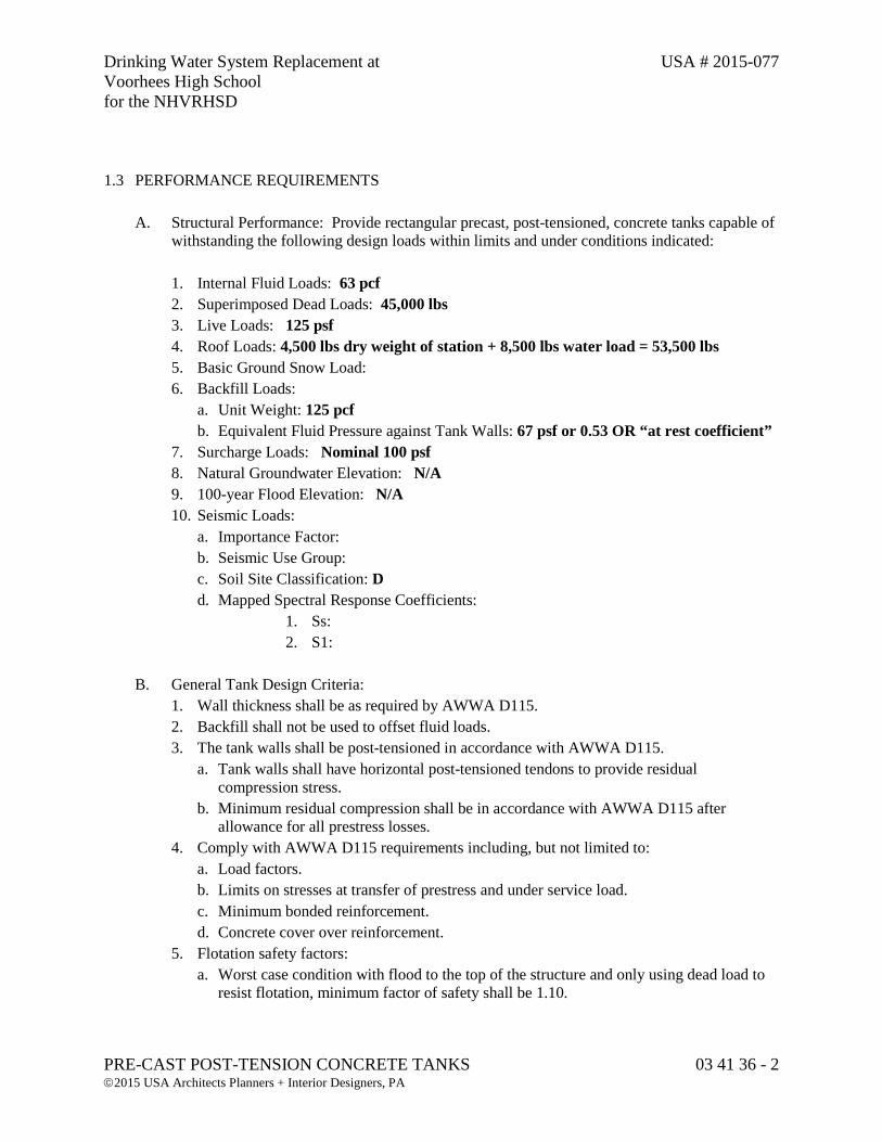
Drinking Water System Replacement at USA # 2015-077 Voorhees High School for the NHVRHSD
PRE-CAST POST-TENSION CONCRETE TANKS 03 41 36 - 2 2015 USA Architects Planners + Interior Designers, PA
1.3 PERFORMANCE REQUIREMENTS
A. Structural Performance: Provide rectangular precast, post-tensioned, concrete tanks capable of withstanding the following design loads within limits and under conditions indicated:
1. Internal Fluid Loads: 63 pcf 2. Superimposed Dead Loads: 45,000 lbs 3. Live Loads: 125 psf 4. Roof Loads: 4,500 lbs dry weight of station + 8,500 lbs water load = 53,500 lbs 5. Basic Ground Snow Load: 6. Backfill Loads:
a. Unit Weight: 125 pcf b. Equivalent Fluid Pressure against Tank Walls: 67 psf or 0.53 OR “at rest coefficient”
7. Surcharge Loads: Nominal 100 psf 8. Natural Groundwater Elevation: N/A 9. 100-year Flood Elevation: N/A 10. Seismic Loads:
a. Importance Factor: b. Seismic Use Group: c. Soil Site Classification: D d. Mapped Spectral Response Coefficients:
1. Ss: 2. S1:
B. General Tank Design Criteria:
1. Wall thickness shall be as required by AWWA D115. 2. Backfill shall not be used to offset fluid loads. 3. The tank walls shall be post-tensioned in accordance with AWWA D115.
a. Tank walls shall have horizontal post-tensioned tendons to provide residual compression stress.
b. Minimum residual compression shall be in accordance with AWWA D115 after allowance for all prestress losses.
4. Comply with AWWA D115 requirements including, but not limited to: a. Load factors. b. Limits on stresses at transfer of prestress and under service load. c. Minimum bonded reinforcement. d. Concrete cover over reinforcement.
5. Flotation safety factors: a. Worst case condition with flood to the top of the structure and only using dead load to
resist flotation, minimum factor of safety shall be 1.10.
Drinking Water System Replacement at USA # 2015-077 Voorhees High School for the NHVRHSD
PRE-CAST POST-TENSION CONCRETE TANKS 03 41 36 - 3 2015 USA Architects Planners + Interior Designers, PA
b. All other cases not included above, whether due to flood or natural groundwater, minimum factor of safety shall be 1.25.
6. The tank structure shall be designed to resist low to medium strength residential wastewater.
7. Design rectangular precast, post-tensioned, concrete tanks to allow for fabrication and construction tolerances, and to accommodate deflection, shrinkage and creep of primary tank structure. Maintain structural precast concrete deflections within limits of ACI 350.
C. Base Slab Design Criteria:
1. Design the base slab to resist all imposed loads within the allowable bearing capacity listed below. a. Allowable Net Bearing Capacity: 2,000 psf (from Geotechnical Evaluation) b. Subgrade Modulus: c. Refer to Geotechnical Evaulation by Maser Consulting P.A. dated March 21, 2016
(Revised) for additional foundation design recommendations. 2. Minimum reinforcement in each orthogonal direction shall be in accordance with ACI 350.
1.4 ACTION SUBMITTALS
A. Product Data: For each type of product indicated. B. Design Mixtures: For each concrete mixture. Include minimum required compressive
strength. C. Shop (Erection) Drawings:
1. Indicate configuration, thickness, dimensions and details of cast-in-place concrete base
slab. 2. Indicate size, spacing and details of all necessary base slab reinforcing. 3. Indicate plan views, elevations, sections, and details necessary to install the tank. 4. Indicate locations of all post-tensioned tendons. 5. Indicate tendon stressing sequence and force, and theoretical elongations for all post-
tensioned tendons. 6. Include and locate all pipe penetrations. Indicate all penetration styles. 7. Coordinate and indicate openings required by other trades. 8. Indicate location of each precast concrete member by same identification mark placed on
unit. 9. Indicate relationship of structural precast concrete members to adjacent materials. 10. Indicate locations and details of joint treatment. 11. Indicate shim sizes and grout requirements. 12. Indicate bearing pad sizes and materials.
Drinking Water System Replacement at USA # 2015-077 Voorhees High School for the NHVRHSD
PRE-CAST POST-TENSION CONCRETE TANKS 03 41 36 - 4 2015 USA Architects Planners + Interior Designers, PA
D. Comprehensive engineering design signed and sealed by a qualified professional engineer
responsible for its preparation licensed in the state of New Jersey. 1.5 INFORMATIONAL SUBMITTALS
A. Qualification Data: For Tank Supplier and persons specified in "Quality Assurance" Article to demonstrate their capabilities and experience. Include list of completed projects with project names and addresses, names and addresses of engineers and owners, and other information specified.
B. Material Certificates: Signed by manufacturers certifying that each of the following items
complies with requirements.
1. Cementitious materials. 2. Aggregates. 3. Reinforcing materials and post-tensioning strands. 4. Admixtures. 5. Bearing pads. 6. Other components specified in Contract Documents with applicable standards.
C. Provide handling procedures, erection sequences, and temporary bracing as required for special
conditions.
D. Field quality-control test reports. 1.6 QUALITY ASSURANCE
A. Tank Supplier Qualifications: A firm that complies with the following requirements and is experienced in producing rectangular precast, post-tensioned, concrete tanks that have a record of successful in-service performance. 1. Assumes responsibility for engineering rectangular precast, post-tensioned, concrete tanks
to comply with performance requirements. This responsibility includes preparation of Shop Drawings and comprehensive engineering analysis by a qualified professional engineer.
2. Precast Tank Engineer Qualifications: A professional engineer licensed in jurisdiction
where Project is located and who is experienced in providing engineering services of the kind indicated. Engineering services are defined as those performed for designs and installations of rectangular precast, post-tensioned, concrete tanks.
Drinking Water System Replacement at USA # 2015-077 Voorhees High School for the NHVRHSD
PRE-CAST POST-TENSION CONCRETE TANKS 03 41 36 - 5 2015 USA Architects Planners + Interior Designers, PA
3. Participates in PCI’s Plant Certification program and is designated a PCI-certified plant for Group C, Category C3.
a. Certification shall be maintained throughout the production of the precast concrete units.
Production shall immediately stop if at any time the fabricator’s certification is revoked, regardless of the status of completion of contracted work. Production will not be allowed to re-start until the necessary corrections are made and certification has been re-established. In the event certification cannot be re-established in a timely manner to avoid project delays, the fabricator, at no additional cost, will contract out the remainder of the units to be manufactured at a PCI certified plant.
4. Has sufficient production capacity to produce required members to meet the project
schedule. 5. The firm shall have a minimum of 15 consecutive years in designing, producing and
installing tanks of similar arrangement, size and complexity using the precast, post-tensioned system.
6. The firm shall document the successful installation and performance of a minimum of ten similar facilities, and certify compliance of those structures will all applicable provisions of AWWA D115 for a precast, post-tensioned structure.
7. The firm shall employ a full-time engineer on staff who meets the Precast Tank Engineer Qualifications listed above and who has served as the engineer in responsible charge of at least ten similar structures.
8. The firm shall submit a summary sheet documenting compliance with these qualifications. 9. The firm shall submit a reference sheet listing contact names and telephone numbers of at
least five similar structures built by the firm.
B. Tank Supplier: Subject to compliance with requirements, provide rectangular precast, post-tensioned, concrete tanks by Dutchland, Inc. located in Gap, Pennsylvania, or pre-approved equal.
C. Post-Tensioning Manufacturer Qualifications: Fabricating plant certified by PTI according to procedures set forth in PTI's "Manual for Certification of Plants Producing Unbonded Single Strand Tendons."
D. Post-Tensioning Installer Qualifications: A qualified installer whose full-time Project superintendent has successfully completed PTI's Level 1 Unbonded PT - Field Installation course.
1. Superintendent must receive training from post-tensioning supplier in the operation of
stressing equipment to be used on Project.
Drinking Water System Replacement at USA # 2015-077 Voorhees High School for the NHVRHSD
PRE-CAST POST-TENSION CONCRETE TANKS 03 41 36 - 6 2015 USA Architects Planners + Interior Designers, PA
E. Post-Tensioning Inspector Qualifications: Personnel performing field inspections and measuring elongations shall have successfully completed PTI's Level 2 Unbonded PT - Inspector course.
F. Design Standards: Comply with AWWA D115, “Tendon-Prestressed Concrete Water Tanks,” ACI 350, “Code Requirements for Environmental Concrete Structures” and the design recommendations of PCI MNL 120, “PCI Design Handbook – Precast and Prestressed Concrete,” applicable to types of structural precast concrete members indicated.
G. Quality-Control Standard: For manufacturing procedures and testing requirements and quality
control recommendations for types of members required, comply with PCI MNL 116, “Manual for Quality Control for Plants and Production of Structural Concrete Products.”
1. Comply with dimensional tolerances of PCI MNL 135, “Tolerance Manual for Precast and
Prestressed Concrete Construction.”
H. Referenced Standards: 1. ACI 117, “Standard Specifications for Tolerances for Concrete Construction and
Materials” 2. ACI 301, “Specifications for Structural Concrete” 3. ACI 318, “Building Code Requirements for Structural Concrete” 4. ACI 350, “Code Requirements for Environmental Engineering Concrete Structures” 5. ACI 350.1, “Specification for Tightness Testing of Environmental Engineering Concrete
Containment Structures” 6. ACI 350.3, “Seismic Design of Liquid-Containing Concrete Structures” 7. ACI 350.4R, “Design Considerations for Environmental Engineering Concrete Structures” 8. ACI 350.5, “Specifications for Environmental Concrete Structures” 9. ACI 423.7, “Specification for Unbonded Single-Strand Tendon Materials and
Commentary” 10. ASCE 7, “Minimum Design Loads for Buildings and Other Structures” 11. AWS D1.4, “Structural Welding Code – Reinforcing Steel” 12. AWWA D115, “Tendon-Prestressed Concrete Water Tanks” 13. PCI MNL-116, “Manual for Quality Control for Plants and Production of Structural
Concrete Products” 14. PCI MNL-120, “PCI Design Handbook – Precast and Prestressed Concrete” 15. PCI MNL-135, “Tolerance Manual for Precast and Prestressed Concrete Construction” 16. PTI TAB.1, “Post-Tensioning Manual” 17. PTI M10.2, “Specification for Unbonded Single Strand Tendons” 18. PTI M10.3, “Field Procedures Manual for Unbonded Single Strand Tendons” 19. PTI M55.1, “Specification for Grouting of Post-Tensioned Structures”
Drinking Water System Replacement at USA # 2015-077 Voorhees High School for the NHVRHSD
PRE-CAST POST-TENSION CONCRETE TANKS 03 41 36 - 7 2015 USA Architects Planners + Interior Designers, PA
I. Tank designs that rely on bolted or welded connections, or ship-lap joints, for primary, fluid-retaining walls shall not be allowed.
J. Shotcrete shall not be allowed.
1.7 DELIVERY, STORAGE, AND HANDLING
A. Deliver, store, and handle post-tensioning materials according to PTI's "Field Procedures Manual for Unbonded Single Strand Tendons.”
B. Deliver all precast concrete members in such quantities and at such times to assure compliance with the agreed upon project schedule and setting sequence to ensure continuity of installation.
C. Handle and transport precast concrete members in a manner to avoid excessive stresses that
could cause cracking or other damage. D. Store precast concrete members with adequate dunnage and bracing, and protect units to
prevent contact with soil, staining, and to control cracking, distortion, warping or other physical damage.
E. Contractor to ensure that all shipments to Voorhees High School use an alternate route when
necessary to avoid constrictive bridge clearance and/or weight load restrictions. Such a constriction exists within the borough of High Bridge, New Jersey along Hunterdon County Route 513 with a railroad underpass clearance of 12’6”. A possible alternative route from Interstate Highway 78 in Clinton, New Jersey is State Route 31 North; to Cregar Road East, crossing over the railroad; and Hunterdon County Route 513 North to Voorhees High School.
F. Contractor shall note that the normal access to the project site on the Voorhees High School campus includes an underpass with a posted clearance restriction of 13’6”. Contractor shall field verify. Should shipments exceed this limit, coordination with North Hunterdon-Voorhees Regional High School District must be made for site access directly from County Route 513 over lawn area. Contractor is responsible for lawn restoration.
PART 2 – PRODUCTS 2.1 MANUFACTURERS
A. Source Limitations: Obtain post-tensioning materials and equipment from single source.
Drinking Water System Replacement at USA # 2015-077 Voorhees High School for the NHVRHSD
PRE-CAST POST-TENSION CONCRETE TANKS 03 41 36 - 8 2015 USA Architects Planners + Interior Designers, PA
2.2 FORM MATERIALS
A. Forms: Rigid, dimensionally stable, nonabsorptive material, warp and buckle free, that will provide precast concrete surfaces within fabrication tolerances indicated; nonreactive with concrete and suitable for producing required surface finishes.
1. Form-Release Agent: Commercially produced form-release agent that will not bond with,
stain or affect hardening of precast concrete surfaces and will not impair subsequent surface or joint treatments of precast concrete.
2.3 NON-PRESTRESSED REINFORCING STEEL
A. Reinforcing Bars: ASTM A 615, Grade 60, deformed.
B. Low-Alloy-Steel Reinforcing Bars: ASTM A 706, deformed. C. Welded Wire Reinforcement: ASTM A 1064, plain or deformed, flat sheet.
D. Supports: Use bolsters, chairs, spacers, and other devices for spacing, supporting, and
fastening reinforcing bars and welded wire reinforcement in place according to PCI MNL 116. 2.4 PRESTRESSING TENDONS
A. ACI Publications: Comply with ACI 423.7, "Specification for Unbonded Single Strand Tendon Materials and Commentary."
B. Prestressing Strand: ASTM A 416, Grade 270, 7-wire, low-relaxation, 0.6-inch-diameter strand with corrosion inhibitor conforming to ACI 423.7, with polypropylene tendon sheathing.
C. Post-Tensioning Coating: Compound with friction-reducing, moisture-displacing, and
corrosion-inhibiting properties; chemically stable and nonreactive with prestressing steel, nonprestressed reinforcement, sheathing material, and concrete.
D. Tendon Sheathing:
1. Virgin high-density polyethylene or polypropylene with a minimum thickness of 50 mils. 2. Continuous over the length of tendon to provide watertight encapsulation of strand.
E. Anchorage Device and Coupler Assembly: Assembly of strand, wedges, and anchorage device
or coupler complying with static and fatigue testing requirements and capable of developing 95 percent of actual breaking strength of strand.
Drinking Water System Replacement at USA # 2015-077 Voorhees High School for the NHVRHSD
PRE-CAST POST-TENSION CONCRETE TANKS 03 41 36 - 9 2015 USA Architects Planners + Interior Designers, PA
1. Anchorage devices and coupler assemblies shall be fully-encapsulated with either plastic or epoxy coating.
F. Encapsulation System: Watertight encapsulation of prestressing strand consisting of the
following:
1. Wedge-Cavity Caps: Attached to anchorages with a positive mechanical connection and completely filled with post-tensioning coating.
2. Sleeves: Attached to anchorage device with positive mechanical connection; overlapped a minimum of 4 inches with sheathing and completely filled with post-tensioning coating.
3. The encapsulation system shall meet the hydrostatic pressure testing requirements of ACI 423.7, except with a hydrostatic pressure of 10 psi, instead of the specified 1.25 psi.
2.5 ACCESSORIES
A. Sheathing Repair Tape: Elastic, self-adhesive, moistureproof tape with minimum width of 2 inches (50 mm), in contrasting color to tendon sheathing; nonreactive with sheathing, coating, or prestressing steel.
2.6 CONCRETE MATERIALS
A. Portland Cement: ASTM C 150, Type II or Type I/II.
1. For surfaces exposed to view in finished structure, use same type, brand, and mill source throughout the precast concrete production.
B. Supplementary Cementitious Materials
1. Fly Ash: ASTM C 618, Class F with maximum loss on ignition of 6%.
C. Normalweight Aggregates: Except as modified by PCI MNL 116, ASTM C 33, with coarse, non-reactive aggregates. Stockpile fine and coarse aggregates for each type of exposed finish from a single source (pit or quarry) for Project.
D. Water: Potable; free from deleterious material that may affect color stability, setting, or
strength of concrete and complying with chemical limits of PCI MNL 116.
E. Air Entraining Admixture: ASTM C 260, certified by manufacturer to be compatible with other required admixtures.
F. Chemical Admixtures: Certified by manufacturer to be compatible with other admixtures and
to not contain calcium chloride or more than 0.15 percent chloride ions or other salts by weight of admixture.
Drinking Water System Replacement at USA # 2015-077 Voorhees High School for the NHVRHSD
PRE-CAST POST-TENSION CONCRETE TANKS 03 41 36 - 10 2015 USA Architects Planners + Interior Designers, PA
1. Water-Reducing Admixture: ASTM C 494/C 494M, Type A. 2. Retarding Admixture: ASTM C 494/C 494M, Type B. 3. Water-Reducing and Retarding Admixture: ASTM C 494/C 494M, Type D. 4. Water-Reducing and Accelerating Admixture ASTM C494/C 494M, Type E. 5. High Range, Water-Reducing Admixture: ASTM C 494/C 494M, Type F. 6. High-Range, Water-Reducing and Retarding Admixture: ASTM C 494/C 494M, Type G. 7. Plasticizing Admixture for Flowable Concrete: ASTM C 1017/C 1017M.
2.6 STEEL EMBEDDED MATERIALS
A. Carbon-Steel Shapes and Plates: ASTM A 36/A 36M B. Carbon-Steel Headed Studs: ASTM A 108, Grades 1010 through 1020, cold finished, AWS
D1.1/D1.1M, Type A or B, with arc shields and with the minimum mechanical properties of PCI MNL 116, Table 3.2.3.
C. Deformed-Steel Wire or Bar Anchors: ASTM A 496 or ASTM A 706/A 706M.
D. Zinc-Coated Finish: For exterior steel items and items indicated for galvanizing, apply zinc
coating by hot-dip process according to ASTM A 123, after fabrication.
1. Galvanizing Repair Paint: Zinc paint with dry film containing not less than 94 percent zinc dust by weight, and complying with DOD-P-21035B or SSPC-Paint 20.
2.7 STAINLESS-STEEL EMBEDDED MATERIALS
A. Stainless-Steel Plate: ASTM A 666, Type 304, Type 316, or Type 201, of grade suitable for application.
B. Stainless-Steel Bolts and Studs: ASTM F 593, alloy 304 or 316, hex-head bolts and studs;
stainless-steel nuts; and flat, stainless-steel washers. C. Stainless-Steel Headed Studs: ASTM A 276, with minimum mechanical properties for studs as
indicated under MNL 116, Table 3.2.3. 2.8 BEARING PADS AND OTHER ACCESSORIES
A. Provide one of the following bearing pads for structural precast concrete members as
recommended by tank supplier for application:
Drinking Water System Replacement at USA # 2015-077 Voorhees High School for the NHVRHSD
PRE-CAST POST-TENSION CONCRETE TANKS 03 41 36 - 11 2015 USA Architects Planners + Interior Designers, PA
1. Elastomeric Pads: AASHTO M 251, plain, vulcanized, 100 percent polychloroprene (neoprene) elastomer, molded to size or cut from a molded sheet, 50 to 70 Shore A durometer according to ASTM D 2240, minimum tensile strength 2250 psi per ASTM D 412.
2. Random-Oriented, Fiber-Reinforced Elastomeric Pads: Preformed, randomly oriented synthetic fibers set in elastomer. Surface hardness of 70 to 90 Shore A durometer according to ASTM D2240. Capable of supporting a compressive stress of 3000 psi with no cracking, splitting or delaminating in the internal portions of the pad.
3. High-Density Plastic: Multimonomer, nonleaching, plastic strip capable of supporting loads with no visible overall expansion.
B. Erection Accessories: Provide steel plates and brackets, clips, hangers, high density plastic
shims, and other accessories required to install precast concrete members.
2.9 GROUT MATERIALS
A. Nonshrink Grout: Premixed, prepackaged, non-metallic, shrink-resistant grout complying with ASTM C 1107, Grade C. Grout shall not contain chlorides. 1. Acceptable Products:
a. SikaGrout 212®, or approved equal. b. SikaGrout 328®, or approved equal.
2.10 PATCHING MATERIALS
A. One-component, polymer-modified, premixed patching material containing selected silica aggregates and portland cement, suitable for vertical and overhead applications. Do not use material containing chlorides or other chemicals known to be deleterious to prestressing steel or material that is reactive with prestressing steel, anchorage device material, or concrete. 1. Manufacturers: Subject to compliance with requirements, provide products by one of the
following: a. ProSpec® BlendCrete, or approved equal.
2.11 CONCRETE MIXTURES
A. Prepare design mixtures for each type of concrete required.
1. Limit use of fly ash to 25 percent replacement of portland cement by weight.
B. Design mixtures may be prepared by a qualified independent testing agency or by qualified
precast plant personnel at Tank Supplier’s option.
Drinking Water System Replacement at USA # 2015-077 Voorhees High School for the NHVRHSD
PRE-CAST POST-TENSION CONCRETE TANKS 03 41 36 - 12 2015 USA Architects Planners + Interior Designers, PA
C. Limit water-soluble chloride ions to maximum percentage by weight of cement permitted by ACI 350 or PCI MNL 116 when tested in accordance with ASTM C 1218/C 1218M.
D. Normalweight Concrete Mixtures: Proportion mixtures by either laboratory trial batch or field
test data methods according to ACI 211.1, with materials to be used on Project, to provide normalweight concrete.
E. Precast Concrete: 1. Compressive Strength (28 Days): 5,000 psi minimum. 2. Maximum Water-Cementitious Materials Ratio: 0.40.
F. Add air-entraining admixture at manufacturer’s prescribed rate to result in concrete at point of placement having an air content complying with PCI MNL 116.
G. When included in design mixtures, add other admixtures to concrete mixtures according to
manufacturer’s written instructions. H. Concrete Mixture Adjustments: Concrete mixture design adjustments may be made if
characteristics of materials, Project conditions, weather, test results, or other circumstances warrant.
2.12 FORM FABRICATION
A. Form: Accurately construct forms, mortar tight, of sufficient strength to withstand pressures due to concrete placement and vibration operations and temperature changes, and for prestressing and detensioning operations. Coat contact surfaces of forms with release agent before reinforcement is placed. Avoid contamination of reinforcement and prestressing tendons by release agent.
B. Maintain forms to provide completed structural precast concrete members of shapes, lines, and
dimensions within fabrication tolerances specified.
1. Edge and Corner Treatment: Uniformly chamfered or as built-in on standard forms. 2.13 FABRICATION
A. Cast-in Plates, Inserts, Angles, and Other Hardware: Fabricate hardware with sufficient
anchorage and embedment to comply with design requirements. Accurately position for attachment of loose hardware and secure in place during precasting operations. Locate hardware where it does not affect position of main reinforcement or concrete placement.
1. Weld headed studs and deformed bar anchors used for anchorage according to AWS
D1.1/D1.1M and AWS C5.4, “Recommended Practices for Stud Welding.”
Drinking Water System Replacement at USA # 2015-077 Voorhees High School for the NHVRHSD
PRE-CAST POST-TENSION CONCRETE TANKS 03 41 36 - 13 2015 USA Architects Planners + Interior Designers, PA
B. Reinforcement: Comply with recommendations in PCI MNL 116 for fabricating, placing, and
supporting reinforcement.
1. Clean reinforcement of loose rust and mill scale, earth, and other materials that reduce or destroy the bond with concrete. When damage to epoxy coated reinforcing exceeds limits specified in ASTM A 775, repair with patching material compatible with coating material and epoxy coat bar ends after cutting.
2. Accurately position, support, and secure reinforcement against displacement during concrete-placement and consolidation operations. Locate and support reinforcement by plastic tipped or corrosion resistant metal or plastic chairs, runners, bolsters, spacers, hangers, and other devices for spacing, supporting, and fastening reinforcing bars and welded wire reinforcement in place according to PCI MNL 116.
3. Provide cover requirements in accordance with ACI 350. Arrange, space, and securely tie bars and bar supports to hold reinforcement in position while placing concrete.
4. Install welded wire reinforcement in lengths as long as practicable. Lap adjoining pieces in accordance with ACI 350 and wire tie laps, where required by design. Offset laps of adjoining widths to prevent continuous laps in either direction.
C. Reinforce structural precast concrete members to resist handling, transportation, and erection
stresses, and specified in-place loads, whichever governs.
D. Comply with requirements in PCI MNL 116 and in this Section for measuring, mixing, transporting, and placing concrete. After concrete batching, no additional water may be added.
E. Place concrete in a continuous operation to prevent cold joints or planes of weakness from
forming in precast concrete members.
F. Place self-consolidating concrete with minimal vibration without dislocating or damaging reinforcement and built-in items, and minimize pour lines, honeycombing or entrapped air voids on surfaces. Use equipment and procedures complying with PCI MNL 116.
G. Comply with PCI MNL 116 procedures for hot and cold-weather concrete placement. H. Identify pickup points of precast concrete members and orientation in structure with permanent
markings, complying with markings indicated on Shop Drawings. Imprint or permanently mark casting date on each precast concrete member on a surface that will not show in finished structure.
I. Cure concrete, according to requirements in PCI MNL 116, by moisture retention without heat
or by accelerated heat curing using live steam or radiant heat and moisture. Cure members until compressive strength is high enough to ensure that stripping does not have an effect on the performance of final product.
Drinking Water System Replacement at USA # 2015-077 Voorhees High School for the NHVRHSD
PRE-CAST POST-TENSION CONCRETE TANKS 03 41 36 - 14 2015 USA Architects Planners + Interior Designers, PA
2.14 WATERSTOPS
A. Flexible PVC Waterstops: Corp of Engineers CRD-C 572 for embedding in concrete construction joints to prevent the passage of fluids through joints. Factory-fabricate corners, intersections and directional changes.
1. Profile: Ribbed without center bulb. 2. Dimensions: 6 inches by 3/8-inch-thick, non-tapered. 3. Acceptable Products:
a. Greenstreak PVC Waterstop #679, or approved equal.
B. Self-Expanding Rubber Strip Waterstops: Manufactured rectangular or trapezoidal strip, bentonite-free, hydrophilic polymer modified chloroprene rubber, for adhesive bonding to concrete.
1. Acceptable Products:
a. Greenstreak Hydrotite® CJ-1030-4M, or approved equal.
C. Self-Expanding Extrudable Waterstops: Extrudable, swelling, bentonite-free, one-part polyurethane.
1. Acceptable Products:
a. SikaSwell® S-2, or approved equal
2.15 RELATED MATERIALS
A. Joint/Crack Filler: ASTM C 920, Type S, Grade NS, Class 35 one-part polyurethane, elastomeric sealant, for sealing precast panel joints and minor cracks.
1. Acceptable Products:
a. Sikaflex®-1a, or approved equal
B. High-Performance Joint Filler: ASTM C 920, Type S, Grade NS, Class 100/20 low-modulus, high-performance, one-part polyurethane-based, elastomeric sealant, for sealing precast panel joints subject to movement.
1. Acceptable Products:
a. Sikaflex®-15 LM, or approved equal
C. Sealant/Adhesive Primer: Specially-formulated primer to promote adhesion of sealants and adhesives to concrete.
1. Acceptable Products:
a. Sikaflex® 429/202, or approved equal
Drinking Water System Replacement at USA # 2015-077 Voorhees High School for the NHVRHSD
PRE-CAST POST-TENSION CONCRETE TANKS 03 41 36 - 15 2015 USA Architects Planners + Interior Designers, PA
D. Joint Sealant, Epoxy: High-build, two-part, protective, solvent-free epoxy.
1. Acceptable Products: a. Sikagard® 62, or approved equal
E. Joint Sealant, Urethane: Liquid-applied, elastomeric, urethane.
1. Acceptable Products:
a. CIM 2000 for potable water tanks, or approved equal
F. Epoxy Injection Adhesive: Two-part, moisture-tolerant, epoxy injection adhesive. 1. Acceptable Products:
a. Sikadur® 52, or approved equal
G. Chemical Grout: Expanding, polyurethane, chemical grout. 1. Acceptable Products:
a. SikaFix® HH+, or approved equal
2.16 FABRICATION TOLERANCES
A. Fabricate structural precast concrete members of shapes, lines and dimensions indicated, so each finished member complies with PCI MNL 135 product tolerances as well as position tolerances for cast-in items.
2.17 FINISHES
A. Form Finish:
1. Standard Grade: Normal plant-run finish produced in forms that impart a smooth finish to concrete. Surface holes smaller than 1/2 inch caused by air bubbles, normal color variations, form joint marks, and minor chips and spalls are acceptable. Fill air holes greater than 1/4 inch in width that occur in high concentration (more than one per 2 square inches). Major or unsightly imperfections, honeycombs, or structural defects are not permitted. Allowable joint offset limited to 1/8 inch.
B. Smooth steel-trowel finish unformed surfaces. Consolidate concrete, bring to proper level with straightedge, float and trowel to a smooth, uniform finish.
Drinking Water System Replacement at USA # 2015-077 Voorhees High School for the NHVRHSD
PRE-CAST POST-TENSION CONCRETE TANKS 03 41 36 - 16 2015 USA Architects Planners + Interior Designers, PA
2.18 SOURCE QUALITY CONTROL
A. Quality-Control Testing: Test and inspect precast concrete according to PCI MNL 116 requirements. If using self-consolidating concrete also test and inspect according to ASTM C 1611, ASTM C 1712, ASTM 1610, and ASTM C 1621.
B. Strength of precast concrete members will be considered deficient if units fail to comply with
ACI 350 concrete strength requirements.
C. Testing: If there is evidence that strength of precast concrete members may be deficient or may not comply with ACI 350 requirements, fabricator shall employ an independent testing agency to obtain, prepare, and test cores drilled from hardened concrete to determine compressive strength according to ASTM C 42 and ACI 350.
a. Test results shall be reported in writing on the same day that tests are performed, with
copies to Architect, Contractor, and precast concrete fabricator. Test reports shall include the following:
1. Project identification name and number. 2. Date when tests were performed. 3. Name of Tank Supplier. 4. Name of concrete testing agency. 5. Identification letter, name, and type of precast concrete member(s)
represented by core tests; design compressive strength; type of failure; actual compressive strength at breaks, corrected for length-diameter ratio; and direction of applied load to core in relation to horizontal plane of concrete as placed.
D. Patching: If core test results are satisfactory and precast concrete members comply with
requirements, clean and dampen core holes and solidly fill with precast concrete mixture or repair material, and finish to match adjacent precast concrete surfaces.
E. Acceptability. Structural precast concrete members that do not comply with acceptability
requirements in PCI MNL 116, including concrete strength, and manufacturing tolerances, are unacceptable. Chipped, spalled or cracked members may be repaired. Replace unacceptable units with precast concrete members that comply with requirements.
PART 3 – EXECUTION 3.1 PREPARATION
A. Contractor shall prepare subgrade in accordance with the Division 31 Earthwork sections.
Drinking Water System Replacement at USA # 2015-077 Voorhees High School for the NHVRHSD
PRE-CAST POST-TENSION CONCRETE TANKS 03 41 36 - 17 2015 USA Architects Planners + Interior Designers, PA
3.2 EXAMINATION
A. Owner’s Geotechnical Engineer shall inspect and approve the subgrade supporting the tank. B. Unsatisfactory conditions shall be corrected to the satisfaction of the Owner’s Geotechnical
Engineer.
C. Proceed with base slab construction only after unsatisfactory conditions have been corrected.
D. The stone sub-base shall be prepared, leveled, and graded to within ± one inch of stone grade,
as indicated on the approved Tank Supplier’s Shop (Erection) drawings.
E. Excavation shall include a minimum of four feet in plan beyond the perimeter of the approved exterior wall line.
F. Site access roads:
1. Shall be provided and maintained by the Contractor throughout the installation of the base
slab and precast tank structure. 2. Shall be cleared, leveled, stoned, and free of mud to provide 14-feet of vertical clearance
and 14-feet of horizontal clearance. 3. Shall be capable of handling 80,000 pounds GVWR. 4. Shall support live loaded trucks operating under their own power. 5. Shall allow drop-deck, spread axle combinations with 53-ft trailers. This includes a 60-
foot-long sweep radius for corners and egress/regress to roadways.
G. Crane and concrete pump pads:
1. Shall be provided and maintained by the Contractor. 2. Shall be cleared, leveled, stoned, and free of mud. 3. Tank Supplier shall communicate the required locations and sizes of the pads with the
Contractor.
3.3 CAST-IN-PLACE CONCRETE BASE SLAB
A. Install the base slab in accordance with Section 03 11 11 Cast-in-Place Concrete Slab.
Drinking Water System Replacement at USA # 2015-077 Voorhees High School for the NHVRHSD
PRE-CAST POST-TENSION CONCRETE TANKS 03 41 36 - 18 2015 USA Architects Planners + Interior Designers, PA
3.4 ERECTION
A. Erect structural precast concrete level, plumb and square within the specified allowable erection tolerances. Provide temporary bracing as required to maintain position, stability, and alignment of members until permanent connections are completed.
1. Install temporary plastic spacing shims as necessary as precast concrete members are being
erected. 2. Use patching material to fill voids within recessed lifting devices flush with surface of
adjacent precast concrete surfaces when recess is exposed.
B. Install post-tensioning tendons as soon as practical. C. Grouting or Dry-Packing Connections and Joints: Indicate joints to be grouted and any critical
grouting sequences on Shop (Erection) Drawings. Grout open spaces at keyways, connections and joints where required or indicated with non-shrink, non-metallic grout. Retain flowable grout in place until it gains sufficient strength to support itself. Fill joints completely without seepage to other surfaces. Alternatively, pack spaces with stiff dry pack grout material, tamping until voids are completely filled. Promptly remove grout material from exposed surfaces before it hardens.
D. Field cutting of precast concrete members is not permitted without approval of the Precast
Tank Engineer.
3.5 ERECTION TOLERANCES
A. Erect structural precast concrete members level, plumb, square and in alignment without exceeding the noncumulative erection tolerances of PCI MNL 135.
3.6 TENDON INSTALLATION
A. Inspect sheathing for damage before installing tendons. Repair damaged areas by restoring post-tensioning coating and repairing or replacing tendon sheathing.
a. Ensure that sheathing is watertight and there are no air voids. b. Follow tape repair procedures in PTI's "Field Procedures Manual for Unbonded Single
Strand Tendons."
B. Immediately remove and replace tendons that have damaged strand.
Drinking Water System Replacement at USA # 2015-077 Voorhees High School for the NHVRHSD
PRE-CAST POST-TENSION CONCRETE TANKS 03 41 36 - 19 2015 USA Architects Planners + Interior Designers, PA
3.7 TENDON STRESSING
A. Stressing jacks and gauges shall be individually identified and calibrated to known standards at intervals not exceeding six months. Exercise care in handling stressing equipment to ensure that proper calibration is maintained.
B. Stress tendons only under supervision of a qualified post-tensioning superintendent.
C. Tendon stressing shall not begin until grout strength in the joints has attained at least 2,500 psi compressive strength.
D. Tendon stressing shall be performed in the sequence indicated on the Shop (Erection) Drawings.
E. Mark and measure elongations according to PTI's "Field Procedures Manual for Unbonded
Single Strand Tendons." Measure elongations to closest 1/8-inch.
F. Tendon elongations shall be recorded and compared to the theoretical elongations indicated on the Shop (Erection) Drawings. Prestressing will be considered acceptable if gage pressures shown on stressing record correspond to required stressing force and theoretical and measured elongations agree.
G. In the event that measured elongations exceed the tolerances indicated on the Shop (Erection)
Drawings, the Precast Tank Engineer shall be notified for resolution.
3.8 TENDON FINISHING
A. Strand tails may be cut once prestressing has been deemed acceptable.
B. Do not cut strand tails or cover anchorages of tendons where elongations exceed tolerances until all discrepancies have been resolved to the satisfaction of the Precast Tank Engineer.
C. Cut strand tails as soon as possible after approval of elongations.
D. The tendon tails shall be cut using hydraulic shears.
E. The strand length protruding beyond the wedges after cutting of the tendon tail shall be
between 0.5-inch and 0.75-inch.
F. Wedge-cavity caps shall be installed within one working day after cutting tendon tails.
Drinking Water System Replacement at USA # 2015-077 Voorhees High School for the NHVRHSD
PRE-CAST POST-TENSION CONCRETE TANKS 03 41 36 - 20 2015 USA Architects Planners + Interior Designers, PA
G. Patch stressing pockets within one day of cutting strand tail. Clean inside surface of pocket to remove laitance or post-tensioning coating before installing patch material. Finish patch material flush with adjacent concrete.
H. If stressing pockets are not able to be filled within ten days after tendon tail cutting, then
temporary protection shall be provided.
3.9 FIELD QUALITY CONTROL
A. Place no concrete for the base slab until the subgrade has been inspected and approved by the Owner’s Geotechnical Engineer.
3.10 PROTECTION OF PRESTRESSED REINFORCEMENT
A. Do not expose tendons to electric ground currents, welding sparks, or temperatures that would degrade components.
B. Prevent water from entering tendons during installation and stressing.
C. Provide weather protection to stressing-end anchorages if strand tails are not cut within 10 days of stressing the tendons.
3.11 REPAIRS
A. Repairs will be permitted provided structural adequacy, serviceability and durability of members are not impaired.
B. Prepare and repair damaged galvanized coatings with galvanizing repair paint according to
ASTM A 780.
C. Repair base slab shrinkage cracks as required for watertightness. Rout a ¼-inch vee-notch along the crack and fill the crack with epoxy injection adhesive.
D. Surface chips or spalls shall be cleaned and then patched with patching material.
E. Misaligned grout ports or connection ports in walkways may be repaired by either enlarging the existing port, or drilling a new one, as required. Coordinate with the Precast Tank Engineer to avoid internal reinforcing and hardware.
F. Damage that occurs during the shipping, installation or construction process shall be brought to
the attention of the Precast Tank Engineer for resolution.
Drinking Water System Replacement at USA # 2015-077 Voorhees High School for the NHVRHSD
PRE-CAST POST-TENSION CONCRETE TANKS 03 41 36 - 21 2015 USA Architects Planners + Interior Designers, PA
G. Additional repairs, if necessary, shall be performed as directed by the Precast Tank Engineer. H. Remove and replace damaged structural precast concrete members when repairs do not comply
with specified requirements. 3.12 CLEANING
A. Clean grout and any other deleterious material from concrete surfaces and adjacent materials immediately.
B. Clean exposed surfaces of precast concrete members after erection and completion of joint
treatment to remove weld marks, other markings, dirt, and stains.
1. Perform cleaning procedures, if necessary, according to precast concrete fabricator’s recommendations. Protect adjacent work from staining or damage due to cleaning operations.
2. Do not use cleaning materials or processes that could change the appearance of exposed concrete finishes or damage adjacent materials.
3.13 TIGHTNESS TESTING
A. Each cell of multi-cell tanks shall be considered a single containment structure and shall be tested individually, unless otherwise specified.
B. The Contractor shall commence tightness testing within five business days of notification that the structure is ready for testing.
1. Contractor shall install all pipe penetrating tank walls and roof with double link-seal and
grout prior to all tank testing.
C. Testing shall be performed using the hydrostatic tightness test, which consists of two parts.
1. Part 1 shall be a qualitative criterion. 2. Part 2 shall be a quantitative criterion expressed as a maximum allowable volume loss of
0.05 percent per 24-hour period.
D. No backfill may be placed against the walls or on the wall footings of the containment structures to be tested, unless otherwise specified.
E. The initial filling of a new containment structure shall not exceed four feet per hour. Filling shall be continued until the water surface is at the design maximum liquid level, or either one
Drinking Water System Replacement at USA # 2015-077 Voorhees High School for the NHVRHSD
PRE-CAST POST-TENSION CONCRETE TANKS 03 41 36 - 22 2015 USA Architects Planners + Interior Designers, PA
inch below any fixed overflow level in covered containment structures or four inches in open containment structures, whichever is lower.
F. Water for the initial filling shall be provided by the Contractor. Use potable water unless
otherwise specified.
G. Part 1 – Qualitative criteria
1. If any water is observed on the containment structure exterior wall surfaces where moisture can be picked up on a dry hand, the containment structure shall be considered to have failed Part 1 of the hydrostatic test.
2. Wet areas on top of the wall footing shall not be cause to fail Part 1 unless the water can be observed to be flowing.
3. Although Part 2 of the test may begin prior to completion of repairs for Part 1, all defects causing the failure of Part 1 shall be repaired before acceptance of the containment structure.
4. The standard repair procedure for areas failing Part 1 is to inject chemical grout into the affected area. Consult with the Precast Tank Engineer before commencing any such repairs.
H. Part 2 – Quantitative criteria
1. Part 2 of the hydrostatic tightness test shall not be scheduled for a period when the
forecast is for a difference of more than 35°F between the ambient temperature readings at the times of the initial and final level measurements of the water surface. The test shall also not be scheduled when the weather forecast indicates the water surface could freeze before the test is completed.
2. The vertical distance to the water surface shall be measured to within 1/16 inch from a fixed point on the containment structure above the water surface. The initial measurement shall not be taken until at least 24 hours after the tank is completely filled. Measurements shall be recorded at 24-hour intervals.
3. The test period shall be the theoretical time required to lower the water surface 3/8 inch, assuming a loss of water at the maximum allowable rate. However, the test period shall not be longer than five days.
4. In uncovered containment structures, evaporation and precipitation shall be measured. 5. At the end of the test period, the water surface shall be recorded to within 1/16 inch at the
location of the original measurements. The water temperature and precipitation measurements shall be recorded.
6. The change in water volume in the containment structure shall be calculated and corrected, if necessary, for evaporation, precipitation, and temperature. If the loss exceeds the required criterion, the containment shall be considered to have failed Part 2 of the test.
Drinking Water System Replacement at USA # 2015-077 Voorhees High School for the NHVRHSD
PRE-CAST POST-TENSION CONCRETE TANKS 03 41 36 - 23 2015 USA Architects Planners + Interior Designers, PA
I. Retesting
1. A restart of the test shall be required when test measurements become unreliable due to unusual precipitation or other external factors.
2. It shall be permitted to immediately retest a containment structure failing Part 2 of the hydrostatic test when Part 1 is passed. If the containment structure fails the second test or if not immediately retested after the first test failure, the interior of the containment structure shall be observed for probable problem areas by the Tank Supplier. The containment structure shall only be retested after the probable problem areas are repaired.
3. Containment structures shall be retested until they meet the required Part 1 and Part 2 criteria. Repairs shall be made before each retest.
J. The containment structure shall be deemed substantially complete upon successful completion
of tightness testing. All final payments, including retainage, for all structural elements related to the precast, post-tensioned tank, including the foundation system and cast-in-place base slab, shall be made at this time. This clause supersedes any conflicting clauses in the contract documents.
3.14 SPECIAL WARRANTY
A. The Tank Supplier shall provide a 10-year structural warranty to the Owner. The warranty shall at minimum include the following items:
1. The Tank Supplier shall provide a corporate guarantee not covered by any form of
insurance or bond as a warranty for the precast tank that warrants the tank is free from structural defect due to faulty design, workmanship, or structural materials.
2. The Tank Supplier shall warrant the structural aspects of the tank for a period of 10 years
from the substantial completion date of the precast tank.
3. The Owner must report in a timely manner any claim to the warranty in writing to the tank manufacturer within the effective coverage dates of the warranty.
4. The Tank Supplier shall furnish, without charge to the Owner, all necessary labor and
materials required to repair all structural defects subject to this warranty with a maximum cost of repair not exceeding the Tank Supplier’s contract value of the tank and under the condition that the Tank Supplier has been paid in full for the project.
B. Specific Exclusions from Warranty:
1. Maintenance items (sealants, coatings, equipment, plumbing, etc.), all non-structural
items.
Drinking Water System Replacement at USA # 2015-077 Voorhees High School for the NHVRHSD
PRE-CAST POST-TENSION CONCRETE TANKS 03 41 36 - 24 2015 USA Architects Planners + Interior Designers, PA
2. Consequential damages, punitive damages, incidental costs, bodily injury, death, and damage to the property other than the tank.
3. Emptying of tanks, inspection of tanks, processing of the water/wastewater, drying or
cleaning of the tanks, filling of tanks, etc. complete in preparation for, and completion of repairs.
4. Defects or issues caused by accident, abuse, misuse, storage or processing of corrosive
liquids, improper maintenance, negligence, modifications, additions, or deletions not made by tank manufacturer, improper or defective application, acts of God, force majeure, untimely action by Owner to minimize damage or losses, unstable or improperly designed or constructed soil/subgrade, or defects caused by work supplied by any party other than the Tank Supplier.
5. A loss or defect that is covered by insurance.
C. All materials and labor for work performed by the Tank Supplier which is not covered under the
standard 10-year limited structural warranty shall be warranted for a period of one (1) year from substantial completion of the tank per the Contract Documents.
3.15 BACKFILL
A. Contractor shall place and compact backfill in accordance with the Division 31 Earthwork sections.
B. Do not commence backfilling around the tank until the tank has been examined and approved by the Engineer of Record.
C. The Contractor shall be responsible to protect the tank from damage by construction activity,
equipment and vehicles. Repair or replace damaged structures to the satisfaction of the Tank Supplier.
D. When backfilling around the tank, place backfill material in equal lifts and to similar elevations
on opposite sides of structures in order to equalize opposing horizontal pressures, except where required for final grading.
E. The excavation shall be kept free of water by the Contractor at all times.
Drinking Water System Replacement at USA # 2015-077 Voorhees High School for the NHVRHSD
PRE-CAST POST-TENSION CONCRETE TANKS 03 41 36 - 25 2015 USA Architects Planners + Interior Designers, PA
PART 1 - PAYMENT
1.1 QUANTITY AND PAYMENT
A. No separate payment shall be made for this section. The cost shall be included within the various items bid in the Proposal.
END OF SECTION 03 41 36

Drinking Water System Replacement at USA # 2015-077
Voorhees High School
for the NHVRHSD
FIRESTOPPING 07 84 00 - 1 2013 USA Architects Planners + Interior Designers, PA
SECTION 07 84 00 - FIRESTOPPING
PART 1 - GENERAL
1.1 RELATED DOCUMENTS
A. Drawings and general provisions of the Contract, including General and Supplementary Conditions
and Division 01 Specification Sections, apply to this Section.
1.2 SUMMARY
A. This Section includes firestopping for the following:
1. Penetrations through fire-resistance-rated assembled partitions including both empty openings
and openings containing cables, pipes, ducts, conduits, and other penetrating items.
2. Sealant joints in fire-resistance-rated construction.
1.3 SYSTEM PERFORMANCE REQUIREMENTS
A. General: Provide firestopping systems that are produced and installed to resist the spread of fire,
according to requirements indicated, and the passage of smoke and other gases.
B. T-Rated Through-Penetration Firestop Systems: Provide through-penetration firestop systems with
T ratings, in addition to F ratings, as determined per ASTM E 814, where indicated and where
systems protect penetrating items exposed to contact with adjacent materials in occupiable floor
areas.
C. Fire-Resistive Joint Sealants: Provide joint sealants with fire-resistance ratings indicated, as
determined per ASTM E 119, but not less than that equaling or exceeding the fire-resistance rating
of the construction in which the joint occurs.
D. For firestopping exposed to view, traffic, moisture, and physical damage, provide products that do
not deteriorate when exposed to these conditions.
1. For piping penetrations for plumbing and wet-pipe sprinkler systems, provide moisture-
resistant through-penetration firestop systems.
2. For floor penetrations with annular spaces exceeding 4 inches (100 mm) or more in width
and exposed to possible loading and traffic, provide firestop systems capable of supporting
the floor loads involved either by installing floor plates or by other means.
3. For penetrations involving insulated piping, provide through-penetration firestop systems not
requiring removal of insulation.
Drinking Water System Replacement at USA # 2015-077
Voorhees High School
for the NHVRHSD
FIRESTOPPING 07 84 00 - 2 2013 USA Architects Planners + Interior Designers, PA
E. For firestopping exposed to view, provide products with flame-spread values of less than 25 and
smoke-developed values of less than 450, as determined per ASTM E 84.
1.4 SUBMITTALS
A. General: Submit the following according to Conditions of Contract and Division 01 Specification
Sections.
B. Product data for each type of product specified.
1. Certification by firestopping manufacturer that products supplied comply with local
regulations controlling use of volatile organic compounds (VOCs) and are nontoxic to
building occupants.
1.5 QUALITY ASSURANCE
A. Fire-Test-Response Characteristics: Provide firestopping that complies with the following
requirements and those specified under the "System Performance Requirements" article:
1. Through-penetration firestop systems are identical to those tested per ASTM E 814 under
conditions where positive furnace pressure differential of at least 0.01 inch of water (2.5
Pa) is maintained at a distance of 0.78 inch (20 mm) below the fill materials surrounding
the penetrating items in the test assembly. Provide rated systems complying with the
following requirements:
a. Through-penetration firestop systems correspond to those indicated by reference to
through-penetration firestop system designations listed by UL in their "Fire Resistance
Directory," by Warnock Hersey, or by another qualified testing and inspecting agency.
B. Information on drawings referring to specific design designations of through-penetration firestop
systems is intended to establish requirements for performance based on conditions that are expected
to exist during installation. Any changes in conditions and designated systems require the
Architect's prior approval. Submit documentation showing that the performance of proposed
substitutions equals or exceeds that of the systems they would replace and are acceptable to
authorities having jurisdiction.
C. Installer Qualifications: Engage an experienced Installer who has completed firestopping that is
similar in material, design, and extent to that indicated for Project and that has performed
successfully.
D. Single-Source Responsibility: Obtain through-penetration firestop systems for each kind of
penetration and construction condition indicated from a single manufacturer.
E. Provide firestopping products containing no detectable asbestos as determined by the method
specified in 40 CFR Part 763, Subpart F, Appendix A, Section 1, "Polarized Light Microscopy."
F. Coordinating Work: Coordinate construction of openings and penetrating items to ensure that
designated through-penetration firestop systems are installed per specified requirements.
Drinking Water System Replacement at USA # 2015-077
Voorhees High School
for the NHVRHSD
FIRESTOPPING 07 84 00 - 3 2013 USA Architects Planners + Interior Designers, PA
1.6 DELIVERY, STORAGE, AND HANDLING
A. Deliver firestopping products to Project site in original, unopened containers or packages with intact
and legible manufacturers' labels identifying product and manufacturer; date of manufacture; lot
number; shelf life, if applicable; qualified testing and inspecting agency's classification marking
applicable to Project; curing time; and mixing instructions for multicomponent materials.
B. Store and handle firestopping materials to prevent their deterioration or damage due to moisture,
temperature changes, contaminants, or other causes.
1.7 PROJECT CONDITIONS
A. Environmental Conditions: Do not install firestopping when ambient or substrate temperatures are
outside limits permitted by firestopping manufacturers or when substrates are wet due to rain, frost,
condensation, or other causes.
B. Ventilation: Ventilate firestopping per firestopping manufacturers' instructions by natural means or,
where this is inadequate, forced air circulation.
1.8 SEQUENCING AND SCHEDULING
A. Notify Owner's inspection agency at least 1 week in advance of firestopping installations; confirm
dates and times on days preceding each series of installations.
B. Do not cover up those firestopping installations that will become concealed behind other
construction until Owner's inspection agency and authorities having jurisdiction, if required, have
examined each installation.
PART 2 - PRODUCTS
2.1 FIRESTOPPING, GENERAL
A. Compatibility: Provide firestopping composed of components that are compatible with each other,
the substrates forming openings, and the items, if any, penetrating the firestopping under conditions
of service and application, as demonstrated by firestopping manufacturer based on testing and field
experience.
B. Accessories: Provide components for each firestopping system that are needed to install fill
materials and to comply with "System Performance Requirements" article in Part 1. Use only
components specified by the firestopping manufacturer and approved by the qualified testing and
inspecting agency for the designated fire-resistance-rated systems. Accessories include but are not
limited to the following items:
1. Temporary forming materials.
Drinking Water System Replacement at USA # 2015-077
Voorhees High School
for the NHVRHSD
FIRESTOPPING 07 84 00 - 4 2013 USA Architects Planners + Interior Designers, PA
2. Substrate primers.
3. Collars.
4. Steel sleeves.
C. Applications: Provide firestopping systems composed of materials specified in this Section that
comply with system performance and other requirements.
2.2 FILL MATERIALS FOR THROUGH-PENETRATION FIRESTOP SYSTEMS
A. Silicone Sealant: Moisture-curing, single-component, silicone-based, neutral-curing elastomeric
sealant of grade indicated below:
1. Grade: Pourable (self-leveling) formulation for openings in floors and other horizontal
surfaces and nonsag formulation for openings in vertical and other surfaces requiring a
nonslumping/ gunnable sealant, unless indicated firestop system limits use to nonsag grade for
both opening conditions.
B. Available Products: Subject to compliance with requirements, products that may be incorporated in
the Work include, but are not limited to, the following:
1. Silicone Sealants:
a. Dow Corning Firestop Sealant 2000, Dow Corning Corp.
b. Dow Corning Firestop Sealant SL 2003, Dow Corning Corp.
c. Pensil 100 Firestop Sealant, General Electric Co.
d. CS240 Firestop Sealant, Hilti Construction Chemicals, Inc.
e. Metacaulk 835, The RectorSeal Corporation.
f. Metacaulk 880, The RectorSeal Corporation.
g. Fyre-Sil, Tremco Inc.
h. Fyre-Sil S/L, Tremco Inc.
2.3 FIRE-RESISTIVE ELASTOMERIC JOINT SEALANTS
A. Elastomeric Sealant Standard: Provide manufacturer's standard chemically curing, elastomeric
sealants of base polymer indicated that complies with ASTM C 920 requirements, including those
referenced for Type, Grade, Class, and Uses, and requirements specified in this Section applicable to
fire-resistive joint sealants.
B. Sealant Colors: Provide color of exposed joint sealants to comply with the following:
1. Provide selections made by Architect from manufacturer's full range of standard colors for
products of type indicated.
C. Single-Component, Neutral-Curing Silicone Sealant: Type S; Grade NS; Class 25; exposure-related
Use NT, and joint-substrate-related Uses M, G, A, and (as applicable to joint substrates indicated) O.
Drinking Water System Replacement at USA # 2015-077
Voorhees High School
for the NHVRHSD
FIRESTOPPING 07 84 00 - 5 2013 USA Architects Planners + Interior Designers, PA
1. Additional Movement Capability: Provide sealant with the capability to withstand the
following percentage changes in joint width existing at time of installation, when tested for
adhesion and cohesion under maximum cyclic movement per ASTM C 719, and remain in
compliance with other requirements of ASTM C 920 for uses indicated:
a. 50 percent movement in both extension and compression for a total of 100 percent
movement.
D. Available Products: Subject to compliance with requirements, products that may be incorporated in
the Work include, but are not limited to, the following:
1. Single-Component, Neutral-Curing, Silicone Sealant:
a. Dow Corning 790, Dow Corning Corp.
b. Dow Corning 795, Dow Corning Corp.
c. Silpruf, General Electric Co.
d. Ultraglaze, General Electric Co.
e. 864, Pecora Corp.
2.4 MIXING
A. For those products requiring mixing prior to application, comply with firestopping manufacturer's
directions for accurate proportioning of materials, water (if required), type of mixing equipment,
selection of mixer speeds, mixing containers, mixing time, and other procedures needed to produce
firestopping products of uniform quality with optimum performance characteristics for application
indicated.
PART 3 - EXECUTION
3.1 EXAMINATION
A. Examine substrates and conditions, with Installer present, for compliance with requirements for
opening configurations, penetrating items, substrates, and other conditions affecting performance of
firestopping. Do not proceed with installation until unsatisfactory conditions have been corrected.
3.2 PREPARATION
A. Surface Cleaning: Clean out openings and joints immediately prior to installing firestopping to
comply with recommendations of firestopping manufacturer and the following requirements:
1. Remove all foreign materials from surfaces of opening and joint substrates and from
penetrating items that could interfere with adhesion of firestopping.
2. Clean opening and joint substrates and penetrating items to produce clean, sound surfaces
capable of developing optimum bond with firestopping. Remove loose particles remaining
from cleaning operation.
Drinking Water System Replacement at USA # 2015-077
Voorhees High School
for the NHVRHSD
FIRESTOPPING 07 84 00 - 6 2013 USA Architects Planners + Interior Designers, PA
3. Remove laitance and form release agents from concrete.
B. Priming: Prime substrates where recommended by firestopping manufacturer using that
manufacturer's recommended products and methods. Confine primers to areas of bond; do not allow
spillage and migration onto exposed surfaces.
C. Masking Tape: Use masking tape to prevent firestopping from contacting adjoining surfaces that
will remain exposed upon completion of Work and that would otherwise be permanently stained or
damaged by such contact or by cleaning methods used to remove smears from firestopping materials.
Remove tape as soon as it is possible to do so without disturbing firestopping's seal with substrates.
3.3 INSTALLING THROUGH-PENETRATION FIRESTOPS
A. Install forming/damming materials and other accessories of types required to support fill materials
during their application and in the position needed to produce the cross-sectional shapes and depths
required to achieve fire ratings of designated through-penetration firestop systems. After installing
fill materials, remove combustible forming materials and other accessories not indicated as
permanent components of firestop systems.
B. Install fill materials for through-penetration firestop systems by proven techniques to produce the
following results:
1. Completely fill voids and cavities formed by openings, forming materials, accessories, and
penetrating items.
3.4 INSTALLING FIRE-RESISTIVE JOINT SEALANTS
A. General: Comply with the "System Performance Requirements" article in Part 1, with ASTM C
1193, and with the sealant manufacturer's installation instructions and drawings pertaining to
products and applications indicated.
B. Install joint fillers to provide support of sealants during application and at position required to
produce the cross-sectional shapes and depths of installed sealants relative to joint widths that allow
optimum sealant movement capability and develop fire-resistance rating required.
C. Install sealants by proven techniques that result in sealants directly contacting and fully wetting joint
substrates, completely filling recesses provided for each joint configuration, and providing uniform,
cross-sectional shapes and depths relative to joint width that optimum sealant movement capability.
Install sealants at the same time joint fillers are installed.
D. Tool nonsag sealants immediately after sealant application and prior to the time skinning or curing
begins. Form smooth, uniform beads of configuration indicated or required to produce fire-
resistance rating, as well as to eliminate air pockets, and to ensure contact and adhesion of sealants
with sides of joint. Remove excess sealant from surfaces adjacent to joint. Do not use tooling agents
that discolor sealants or adjacent surfaces or are not approved by sealant manufacturer.
Drinking Water System Replacement at USA # 2015-077
Voorhees High School
for the NHVRHSD
FIRESTOPPING 07 84 00 - 7 2013 USA Architects Planners + Interior Designers, PA
3.5 CLEANING
A. Clean off excess fill materials and sealants adjacent to openings and joints as work progresses by
methods and with cleaning materials approved by manufacturers of firestopping products and of
products in which opening and joints occur.
B. Protect firestopping during and after curing period from contact with contaminating substances or
from damage resulting from construction operations or other causes so that they are without
deterioration or damage at time of Substantial Completion. If, despite such protection, damage or
deterioration occurs, cut out and remove damaged or deteriorated firestopping immediately and
install new materials to produce firestopping complying with specified requirements.
END OF SECTION 07 84 00

Drinking Water System Replacement at USA # 2015-077
Voorhees High School
for the NHVRHSD
JOINT SEALANTS 07 92 00 - 1 2013 USA Architects Planners + Interior Designers, PA
SECTION 07 92 00 - JOINT SEALANTS
PART 1 - GENERAL
1.1 RELATED DOCUMENTS
A. Drawings and general provisions of the Contract, including General and Supplementary Conditions
and Division 01 Specification Sections, apply to this Section.
1.2 SUMMARY
A. This Section includes, but is not limited to, joint sealants for the following locations:
1. Sealant Type 1: Exterior joints in vertical surfaces and horizontal non-traffic surfaces as
indicated below:
a. Control and expansion joints in unit masonry.
b. Joints of stonework set with mortar including copings and cornices.
c. Perimeter joints of frames of doors and windows.
d. Other joints as indicated.
2. Sealant Type 2: Interior and exterior joints in horizontal traffic surfaces as indicated below:
a. Control, expansion, and isolation joints in cast-in-place concrete slabs, sidewalks, tile and
carpet flooring.
3. Sealant Type 3: Interior joints in vertical surfaces and horizontal non-traffic surfaces as
indicated below:
a. Control and expansion joints on exposed interior surfaces of exterior walls.
b. Perimeter joints of exterior openings where indicated.
c. Vertical control joints on exposed surfaces of interior unit masonry and concrete walls and
partitions.
d. Perimeter joints between interior wall surfaces and frames of interior doors, windows, and
elevator entrances.
e. Perimeter joints of toilet fixtures.
f. Other joints as indicated.
4. Sealant Type 4: Interior sanitary joints in vertical and horizontal surfaces as indicated below:
a. Perimeter joints of fixtures in bathroom, lavatory and kitchen applications.
5. Sealant type 5: Interior and exterior joints continuously immersed in water as indicated below:
a. Control and expansion joints in swimming pools and fountains.
6. Sealant Type 6: Interior construction fire rated joints indicated on the drawings:
a. Expansion and control joints on interior masonry and concrete walls.
b. Perimeter joints between interior wall surfaces and frames of interior doors and
windows.
Drinking Water System Replacement at USA # 2015-077
Voorhees High School
for the NHVRHSD
JOINT SEALANTS 07 92 00 - 2 2013 USA Architects Planners + Interior Designers, PA
A. Related Sections:
1. Division 07 Section "Firestopping"
1.3 SUBMITTALS
A. General: Submit the following in accordance with Conditions of Contract and Division 01
Specification Sections.
B. Product Data: For each joint-sealant product indicated.
C. Samples for Initial Selection: Manufacturer's color charts consisting of strips of cured sealants
showing the full range of colors available for each product exposed to view.
D. Samples for Verification: For each kind and color of joint sealant required, provide Samples with
joint sealants in 1/2-inch- (13-mm-) wide joints formed between two 6-inch- (150-mm-) long strips
of material matching the appearance of exposed surfaces adjacent to joint sealants.
E. Joint-Sealant Schedule: Include the following information:
1. Joint-sealant application, joint location, and designation.
2. Joint-sealant manufacturer and product name.
3. Joint-sealant formulation.
4. Joint-sealant color.
1.4 QUALITY ASSURANCE
A. Installer Qualifications: Engage an experienced Installer who has completed joint sealant
applications similar in material, design, and extent to that indicated for Project that have resulted in
construction with a record of successful in-service performance for a period of three years.
B. Single Source Responsibility for Joint Sealant Materials: Obtain joint sealant materials from a single
manufacturer for each different product required.
1.5 DELIVERY, STORAGE, AND HANDLING
A. Deliver materials to Project site in original unopened containers or bundles with labels indicating
manufacturer, product name and designation, color, expiration period for use, pot life, curing time,
and mixing instructions for multicomponent materials.
B. Store and handle materials in compliance with manufacturer's recommendations to prevent their
deterioration or damage due to moisture, high or low temperatures, contaminants, or other causes.
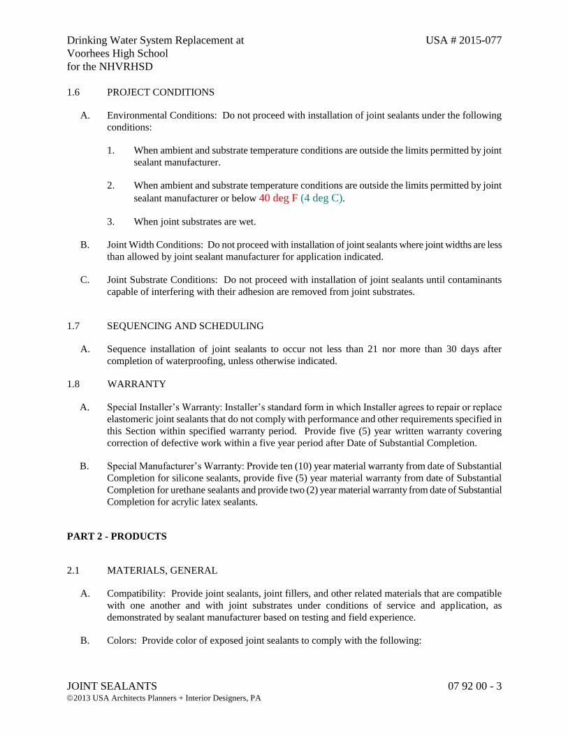
Drinking Water System Replacement at USA # 2015-077
Voorhees High School
for the NHVRHSD
JOINT SEALANTS 07 92 00 - 3 2013 USA Architects Planners + Interior Designers, PA
1.6 PROJECT CONDITIONS
A. Environmental Conditions: Do not proceed with installation of joint sealants under the following
conditions:
1. When ambient and substrate temperature conditions are outside the limits permitted by joint
sealant manufacturer.
2. When ambient and substrate temperature conditions are outside the limits permitted by joint
sealant manufacturer or below 40 deg F (4 deg C).
3. When joint substrates are wet.
B. Joint Width Conditions: Do not proceed with installation of joint sealants where joint widths are less
than allowed by joint sealant manufacturer for application indicated.
C. Joint Substrate Conditions: Do not proceed with installation of joint sealants until contaminants
capable of interfering with their adhesion are removed from joint substrates.
1.7 SEQUENCING AND SCHEDULING
A. Sequence installation of joint sealants to occur not less than 21 nor more than 30 days after
completion of waterproofing, unless otherwise indicated.
1.8 WARRANTY
A. Special Installer’s Warranty: Installer’s standard form in which Installer agrees to repair or replace
elastomeric joint sealants that do not comply with performance and other requirements specified in
this Section within specified warranty period. Provide five (5) year written warranty covering
correction of defective work within a five year period after Date of Substantial Completion.
B. Special Manufacturer’s Warranty: Provide ten (10) year material warranty from date of Substantial
Completion for silicone sealants, provide five (5) year material warranty from date of Substantial
Completion for urethane sealants and provide two (2) year material warranty from date of Substantial
Completion for acrylic latex sealants.
PART 2 - PRODUCTS
2.1 MATERIALS, GENERAL
A. Compatibility: Provide joint sealants, joint fillers, and other related materials that are compatible
with one another and with joint substrates under conditions of service and application, as
demonstrated by sealant manufacturer based on testing and field experience.
B. Colors: Provide color of exposed joint sealants to comply with the following:
Drinking Water System Replacement at USA # 2015-077
Voorhees High School
for the NHVRHSD
JOINT SEALANTS 07 92 00 - 4 2013 USA Architects Planners + Interior Designers, PA
1. Provide selections made by Architect from manufacturer's full range of standard and special
colors for products of type indicated.
2.2 SEALANTS
A. Sealant Type 1: For sealing exterior joints, provide a multi-component polyurethane sealant
complying with ASTM C-920.
1. Provide “Dynatrol II” sealant by Pecora, Dymeric 240 FC by Tremco or approved equal.
B. Sealant Type 2: For sealing interior or exterior joints, provide a multi-component high performance
polyurethane sealant complying with ASTM C-920.
1. Provide Urexpan NR-200/Dynatred sealant by Pecora or approved equal.
C. Sealant Type 3: For all interior joints, provide an acrylic latex, one part non sag sealant compound;
recommended by manufacturer for general use as an interior exposed building construction sealant
complying with ASTM C-834.
1. Provide one of the following:
a. AC -20 + Silicone by Pecora Corporation, Tremflex 834 by Tremco or approved equal.
D. Sealant Type 4: For use at all joints at plumbing fixtures, provide one-part silicone sealant
complying with ASTM C-920 and USDA approval.
1. Provide one of the following:
a. Pecora 898 Silicone, Tremco Tremsil 200 or approved equal.
E. Sealant Type 5: For interior and exterior joints, provide two-part high performance polysulfide
sealant complying with ASTM C-920, C-1247 and NSF Standards 61, Section 6.
1. Provide the following:
a. Synthacalk GC-2+ by Pecora Corporation or approved equal.
2.3 FIRE RATED EXPANSION JOINTS
A. Sealant Type 6: Construction fire rated joints as indicated on the drawings with the following
components complying with ANSI/UL 263 and ASTM E-119, one to four hour ratings.
1. Joint Filler, "Ultra Block" or “Fibrex Mineral Wool” as recommended by Pecora, in thickness
required to fill joints.
2. Joint Sealant, "Dynatrol II" two part polyurethane as manufactured by Pecora.
Drinking Water System Replacement at USA # 2015-077
Voorhees High School
for the NHVRHSD
JOINT SEALANTS 07 92 00 - 5 2013 USA Architects Planners + Interior Designers, PA
2.4 JOINT SEALANT BACKING
A. General: Provide sealant backings of material and type that are nonstaining; are compatible with
joint substrates, sealants, primers and other joint fillers; and are approved for applications indicated
by sealant manufacturer based on field experience and laboratory testing.
B. Plastic Foam Joint Fillers: Preformed, compressible, resilient, nonstaining, nonwaxing,
nonextruding strips of flexible plastic foam of material indicated below and of size, shape, and
density to control sealant depth and otherwise contribute to producing optimum sealant performance:
1. Closed-cell polyethylene foam, nonabsorbent to liquid water and gas, nonoutgassing in
unruptured state.
2. Open-cell polyurethane foam, nonoutgassing backer rod.
C. Elastomeric Tubing Joint Fillers: Neoprene, butyl, EPDM, or silicone tubing complying with
ASTM D 1056, nonabsorbent to water and gas, capable of remaining resilient at temperatures down
to -26 deg F (-32 deg C). Provide products with low compression set and of size and shape to
provide a secondary seal, to control sealant depth, and otherwise contribute to optimum sealant
performance.
D. Bond-Breaker Tape: Polyethylene tape or other plastic tape as recommended by sealant
manufacturer for preventing sealant from adhering to rigid, inflexible joint filler materials or joint
surfaces at back of joint where such adhesion would result in sealant failure. Provide self-adhesive
tape where applicable.
1. Provide Pecora #531 Bond-breaker Tape, or approved equal.
2.5 MISCELLANEOUS MATERIALS
A. Primer: Material recommended by joint sealant manufacturer where required for adhesion of sealant
to joint substrates indicated, as determined from preconstruction joint sealant-substrate tests and field
tests.
B. Cleaners for Nonporous Surfaces: Chemical cleaners acceptable to manufacturers of sealants and
sealant backing materials, free of oily residues or other substances capable of staining or harming in
any way joint substrates and adjacent nonporous surfaces, and formulated to promote optimum
adhesion of sealants with joint substrates.
C. Masking Tape: Nonstaining, nonabsorbent material compatible with joint sealants and surfaces
adjacent to joints.
Drinking Water System Replacement at USA # 2015-077
Voorhees High School
for the NHVRHSD
JOINT SEALANTS 07 92 00 - 6 2013 USA Architects Planners + Interior Designers, PA
PART 3 - EXECUTION
3.1 EXAMINATION
A. Examine joints indicated to receive joint sealants, with Installer present, for compliance with
requirements for joint configuration, installation tolerances, and other conditions affecting joint
sealant performance. Do not proceed with installation of joint sealants until unsatisfactory
conditions have been corrected.
3.2 PREPARATION
A. Surface Cleaning of Joints: Clean out joints immediately before installing joint sealants to comply
with recommendations of joint sealant manufacturer and the following requirements:
1. Remove all foreign material from joint substrates that could interfere with adhesion of joint
sealant, including dust, paints (except for permanent, protective coatings tested and approved
for sealant adhesion and compatibility by sealant manufacturer), old joint sealants, oil, grease,
waterproofing, water repellents, water, surface dirt, and frost.
2. Clean concrete, masonry, unglazed surfaces of ceramic tile, and similar porous joint substrate
surfaces by brushing, grinding, blast cleaning, mechanical abrading, or a combination of these
methods to produce a clean, sound substrate capable of developing optimum bond with joint
sealants. Remove loose particles remaining from above cleaning operations by vacuuming or
blowing out joints with oil-free compressed air.
3. Remove laitance and form release agents from concrete.
4. Clean metal, glass, porcelain enamel, glazed surfaces of ceramic tile, and other nonporous
surfaces with chemical cleaners or other means that do not stain, harm substrates, or leave
residues capable of interfering with adhesion of joint sealants.
B. Joint Priming: Prime joint substrates where indicated or where recommended by joint sealant
manufacturer based on preconstruction joint sealant-substrate tests or prior experience. Apply
primer to comply with joint sealant manufacturer's recommendations. Confine primers to areas of
joint sealant bond; do not allow spillage or migration onto adjoining surfaces.
C. Masking Tape: Use masking tape where required to prevent contact of sealant with adjoining
surfaces that otherwise would be permanently stained or damaged by such contact or by cleaning
methods required to remove sealant smears. Remove tape immediately after tooling without
disturbing joint seal.
3.3 INSTALLATION OF JOINT SEALANTS
A. General: Comply with joint sealant manufacturer's printed installation instructions applicable to
products and applications indicated, except where more stringent requirements apply.
Drinking Water System Replacement at USA # 2015-077
Voorhees High School
for the NHVRHSD
JOINT SEALANTS 07 92 00 - 7 2013 USA Architects Planners + Interior Designers, PA
B. Installation of Sealant Backings: Install sealant backings to comply with the following requirements:
1. Install joint fillers of type indicated to provide support of sealants during application and at
position required to produce the cross-sectional shapes and depths of installed sealants
relative to joint widths that allow optimum sealant movement capability.
a. Do not leave gaps between ends of joint fillers.
b. Do not stretch, twist, puncture, or tear joint fillers.
c. Remove absorbent joint fillers that have become wet prior to sealant application and
replace with dry material.
2. Install bond breaker tape between sealants where backer rods are not used between sealants
and joint fillers or back of joints.
C. Installation of Sealants: Install sealants by proven techniques that result in sealants directly
contacting and fully wetting joint substrates, completely filling recesses provided for each joint
configuration, and providing uniform, cross-sectional shapes and depths relative to joint widths that
allow optimum sealant movement capability. Install sealants at the same time sealant backings are
installed.
D. Tooling of Nonsag Sealants: Immediately after sealant application and prior to time skinning or
curing begins, tool sealants to form smooth, uniform beads of configuration indicated, to eliminate
air pockets, and to ensure contact and adhesion of sealant with sides of joint. Remove excess
sealants from surfaces adjacent to joint. Do not use tooling agents that discolor sealants or adjacent
surfaces or are not approved by sealant manufacturer.
1. Provide concave joint configuration, unless otherwise indicated.
3.4 CLEANING
A. Clean off excess sealants or sealant smears adjacent to joints as work progresses by methods and
with cleaning materials approved by manufacturers of joint sealants and of products in which joints
occur.
3.5 PROTECTION
A. Protect joint sealants during and after curing period from contact with contaminating substances or
from damage resulting from construction operations or other causes so that they are without
deterioration or damage at time of Substantial Completion. If, despite such protection, damage or
deterioration occurs, cut out and remove damaged or deteriorated joint sealants immediately so that
and installations with repaired areas are indistinguishable from original work.
END OF SECTION 07 92 00

Drinking Water System Replacement at USA # 2015-077 Voorhees High School for the NHVRHSD
COMMON WORK RESULTS FOR ELECTRICAL 26 05 00 - 1 2015 USA Architects Planners + Interior Designers, PA
SECTION 26 05 00 – COMMON WORK RESULTS FOR ELECTRICAL
PART 1 - GENERAL
1.1 SCOPE OF WORK
A. Note: This specification is subject to applicable sections of other Divisions of this Work, where equipment and instruments are specified and such equipment and instruments have electrical connections. All work in Division 26 shall meet requirements of this section.
B. This work includes all labor, materials, equipment and services for a complete electrical system. Work includes, but is not limited to the following:
1. Electrical equipment and grounding systems.
2. Furnish and install raceways, conductors, equipment and instruments.
3. Furnish and install electrical devices as required by National Electrical Code.
4. Disconnect and where required demolish electrical work associated with equipment to be removed and associated controls.
5. Create a new service to the new booster station from an existing source within the school building. Provide new conductors and raceways to run the power to the new booster station. Provide an emergency generator and automatic transfer switch. The automatic transfer switch shall be shipped to the builder of the packaged booster station for mounting and wiring. Provide raceways and conductors to run power from new emergency generator to the new booster station where the automatic transfer switch will be located. Provide new raceways and conductors to the well.
6. Demolish or remove from service as necessary, existing power feed to the existing booster pump station, power feed to well from existing booster station, power feed from booster station to chemical feed equipment in chemical feed building.
7. Provide all concrete pads, and footings, ductbanks, supports and penetrations required to accomplish the work.
8. Provide Electrical Studies as specified.
9. Work of the Contractor shall include furnish and install materials, equipment, devices and instruments required to result in a complete and functional system at all required facilities. Furnish and install raceways and conductors required to incorporate new or replaced electrical equipment.
Drinking Water System Replacement at USA # 2015-077 Voorhees High School for the NHVRHSD
COMMON WORK RESULTS FOR ELECTRICAL 26 05 00 - 2 2015 USA Architects Planners + Interior Designers, PA
10. Test all electrical systems to the satisfaction of the Engineer.
C. Under this section provide electric services for and connections to all fixtures, appliances and items of equipment requiring same and shown on any Contract Drawings, specified under this Division, or any other Division of specifications.
D. The Contractor performing electrical work of this Contract shall be licensed to perform work in Annandale, Hunterdon County, NJ. The Contractor shall be responsible for all fees, permits, licenses, and inspections required to accomplish the work.
1.2 LOCAL CONDITIONS
A. Examine the premises and observe the conditions under which work will be done and all other circumstances which will affect the work before submitting bid. The submittal of a bid will indicate that the Contractor has full knowledge of the challenges involved in the performance of the work.
B. Prior to installation of materials and equipment, discrepancies between plans and actual field conditions or between plans and specifications shall be brought to the attention of the Engineer for clarification.
1.3 APPLICABLE CODES AND STANDARDS
A. Unless stated otherwise in the GENERAL CONDITIONS, the currently adopted codes by the enforcing authorities shall govern.
1. NFPA Codes
2. International Building Code (IBC)
3. Local codes
1.4 SUBMITTALS
A. All submittals shall include sufficient data to make a thorough evaluation of features, construction and performance. Submittals shall be bound in booklet form with a cover sheet indicating each item and respective manufacturer’s catalog number and shall indicate if the item is as specified or a substitute.
B. Materials, equipment and fixtures shall completely satisfy specification requirements and be suitable for their intended use. Items of equipment submitted shall include all accessories and options recommended by the manufacturer for satisfactory, reliable and safe operation in its designated location.
Drinking Water System Replacement at USA # 2015-077 Voorhees High School for the NHVRHSD
COMMON WORK RESULTS FOR ELECTRICAL 26 05 00 - 3 2015 USA Architects Planners + Interior Designers, PA
C. Where model number or name of one manufacturer is followed in specifications by one or more other manufacturer’s names, design has been based on first product named and shall be considered to be the specified product or manufacturer, named alternates may require minor deviations. The Contractor shall indicate deviations in submittals/shop drawings.
D. Provide equipment and material specified or named alternates. Products submitted shall be equal in quality to products of the specified manufacturer and shall include the standard features of the specified product and also optional features or necessary changes specified herein. Submittal of alternates shall include all changes in building systems, piping, wiring, supports or accessories required for satisfactory and intended operation. The Engineer shall make all determinations regarding equivalence.
E. Manufacturer’s model and catalog numbers included in the specifications may not include all specified or required features and may not insure compatibility with supporting systems or intended application. Contractor shall insure that material and equipment delivered to job site is suitable for the intended application and indicated connections. Review of shop drawings shall not include review and verification of submitted catalog numbers or quantities required.
F. Review of Contractor’s submitted shop drawings and noted comments on Contractor’s submitted shop drawings does not constitute a change order or a waiver of Contract requirements. In the event of conflict between submittals or shop drawings and Contract Documents, the latter shall govern. If waiver of particular requirement is requested by Contractor, a formal written request shall be made to the Engineer for presentation to the Owner.
G. When directed, Contractor shall provide samples of material or equipment.
H. Equipment shall be shipped or fabricated in sections of suitable size for entering buildings and all necessary arrangements for their installation shall be made by Contractor.
I. Shop drawings and submittals shall bear the Contractor’s review and approval stamp prior to submission to the Engineer.
J. Submit copies of shop drawings for all electrical equipment custom-made for this Contract. If necessary, drawings shall be revised as directed and resubmitted.
K. Manufacturer’s drawings, sketches, and instructions shall supplement but not supersede Contract Drawings and specifications.
L. Submittals shall show:
1. Physical size and arrangement of equipment.
2. Wiring diagrams for all equipment showing all circuit devices, conductor sizes, color coding, type, etc.
3. Elementary control diagrams in straight line form for motor control equipment showing all control devices connected to the system.
Drinking Water System Replacement at USA # 2015-077 Voorhees High School for the NHVRHSD
COMMON WORK RESULTS FOR ELECTRICAL 26 05 00 - 4 2015 USA Architects Planners + Interior Designers, PA
4. Specifications for all components.
1.5 MATERIALS AND ACCESSORIES
A. Materials shall be new and listed by the Underwriters Laboratories, Inc., or locally approved national testing agency as conforming to standards in every case where such a standard has been established for the particular materials in question.
B. Equipment shall be packaged in their original containers and be limited to products regularly produced and recommended for service ratings in accordance with manufacturer’s catalogs, engineering data or other comprehensive literature made available to the public, and in effect at the time of contract award and shall be turned over to the Owner free of all defects.
C. All equipment or materials for any one system shall be furnished by the same manufacturer. Such items as lamps, conduit fittings, wire, electrical switchgear, wiring devices, etc., shall be the same throughout the project.
D. Materials installed on exterior of buildings shall be weather tight and of such design as intended for this purpose.
E. Equipment shall be installed in strict accordance with manufacturer’s instructions for type, capacity and suitability of each piece of equipment used. Use weatherproof equipment where required. Install equipment in accordance with manufacturer’s recommendations and meet conditions for manufacturer’s standard warranty.
F. Contractor shall effectively protect his work, materials, or equipment which are liable to damage during construction period. Openings into any part of conduit system as well as associated fixtures, equipment, both before and after being set in place must be securely covered or otherwise protected to prevent obstruction of conduit or damage due to carelessness, dropped tools or materials, grit, dirt, or any foreign matter. Contractor is responsible for all damage so done until his work is installed and accepted. Conduit ends shall be covered with capped bushings.
G. Provide all accessories, equipment and connections required for complete installation, ready for continuous use by Owner.
1.6 INSPECTION AND REGULATIONS
A. Do not allow or cause any work to be covered up or enclosed until it has been inspected, tested and approved by the authorities having jurisdiction over the work and the Engineer. Should any Work be enclosed or covered before such an inspection and test, Contractor shall, at his own expense, uncover the work and after it has been inspected, tested and approved make all repairs with such material as may be necessary to restore all of his work and that of any other Contractor to its original condition.
Drinking Water System Replacement at USA # 2015-077 Voorhees High School for the NHVRHSD
COMMON WORK RESULTS FOR ELECTRICAL 26 05 00 - 5 2015 USA Architects Planners + Interior Designers, PA
B. Work shall meet requirements of Owner, Township, National Electrical Code, local regulations, and rules of the electric service provider (Utility Company). Equipment and materials shall bear label of approval of National Board of Fire Underwriters and be UL listed for their particular application.
C. Work shall meet requirements of the Owner’s insurer.
1.7 TESTS
A. Give timely notice of intention to test or cover up work to permit observation. Contractor shall test all wiring for continuity and grounds before connecting any equipment or outlets.
1.8 FIELD MEASUREMENTS
A. Visit the site before submitting bid and check location of existing utilities, conditions, verify dimensions and locations shown on the plans and overall costs and work herein described or shown.
B. Take measurements necessary for this work and be responsible for their accuracy. Provide all necessary pull boxes and junction boxes as required to accomplish distribution.
1.9 STRUCTURAL DIFFICULTIES
A. Should structural difficulties prevent performing work, necessary deviations, as determined by Engineer, shall be performed.
1.10 DRAWINGS AND SPECIFICATIONS
A. Drawings shall be considered schematic in nature and shall represent a completed product. Contractor is responsible for installation of equipment and methods of achieving a satisfactory and intended installation. Locations of devices are intended to show a general arrangement and intended function. Door swings and architectural features shall be checked for final condition. Coordinate with all Contract Documents and with other trades.
B. Where a conflict exists between Drawings and Specifications, the Engineer shall be contacted to determine the intent. In all circumstances, the final Contract Document interpretation shall provide compliance with all codes.
C. Wiring devices shall be located uniformly with respect to building structure and other work. Locations shall be coordinated. Should there be any interference between electrical wiring and other trades, Contractor shall notify the Engineer so that proper location may be determined.
D. Maintain a complete set of Contract Documents on the project site. As work is installed, carefully draw on prints, in red colored pencil, correct locations of work installed with dimensions from
Drinking Water System Replacement at USA # 2015-077 Voorhees High School for the NHVRHSD
COMMON WORK RESULTS FOR ELECTRICAL 26 05 00 - 6 2015 USA Architects Planners + Interior Designers, PA
permanent walls, wiring diagrams and details corrected. On completion of project, deliver as-built prints to Owner in good condition.
1.11 PERMITS
A. All permits, licenses or incidental fees shall be borne by the Contractor unless otherwise noted.
1.12 GUARANTEE
A. Unless otherwise specified, guarantee unconditionally for a guarantee period as set forth in General Conditions all materials, workmanship and installation. During this period, adjust, repair or replace, at no cost to the Owner, any item of equipment or workmanship found to be defective.
B. Contractor shall be responsible for and pay for damages caused by or resulting from defects in workmanship.
PART 2 - PRODUCTS (not applicable)
PART 3 - EXECUTION (not applicable)
PART 4 - PAYMENT
4.1 QUANTITY AND PAYMENT
A. No separate payment shall be made for this section. The cost shall be included within the various items bid in the Proposal.
END OF SECTION 26 05 00
Drinking Water System Replacement at USA # 2015-077 Voorhees High School for the NHVRHSD
LOW VOLTAGE ELECTRICAL CONDUCTORS AND CABLES 26 05 19 - 1 2015 USA Architects Planners + Interior Designers, PA
SECTION 26 05 19 – LOW VOLTAGE ELECTRICAL CONDUCTORS AND CABLES
PART 1 - GENERAL
1.1 RELATED DOCUMENTS
A. Drawings and general provisions of the Contract, including General and Supplementary Conditions and Division 01 Specification Sections, apply to this Section.
1.2 SUMMARY
A. This Section includes the following:
1. Building wires and cables rated 600 V and less.
2. Connectors, splices, and terminations rated 600 V and less.
1.3 SUBMITTALS
A. Product Data: For each type of product indicated.
1.4 QUALITY ASSURANCE
A. Comply with NFPA 70.
PART 2 - PRODUCTS
2.1 CONDUCTORS AND CABLES
A. Available Manufacturers: Subject to compliance with requirements, manufacturers offering products that may be incorporated into the Work include, but are not limited to, the following:
1. Alcan Products Corporation; Alcan Cable Division.
2. American Insulated Wire Corp.; a Leviton Company.
3. General Cable Corporation.
4. Senator Wire & Cable Company.
Drinking Water System Replacement at USA # 2015-077 Voorhees High School for the NHVRHSD
LOW VOLTAGE ELECTRICAL CONDUCTORS AND CABLES 26 05 19 - 2 2015 USA Architects Planners + Interior Designers, PA
5. Southwire Company.
B. Copper Conductors: Comply with NEMA WC 70.
C. Conductor Insulation: Comply with NEMA WC 70 for Types THW, THHN-THWN, XHHW, UF, USE, and SO.
1. All spliced conductors shall have the same insulation type on both sides of the splice.
D. Multiconductor Cable: Comply with NEMA WC 70 for metal-clad cable, Type MC with ground wire.
2.2 CONDUCTORS AND SPLICES
A. Available Manufacturers: Subject to compliance with requirements, manufacturers offering products that may be incorporated into the Work include, but are not limited to, the following:
1. AFC Cable Systems, Inc.
2. Hubbell Power Systems, Inc.
3. O-Z/Gedney; EGS Electrical Group LLC.
4. 3M; Electrical Products Division.
5. Tyco Electronics Corp.
6. Ideal Industries Inc.
B. Description: Factory-fabricated connectors and splices of size, ampacity rating, material, type, and class for application and service indicated.
PART 3 - EXECUTION
3.1 CONDUCTOR MATERIAL APPLICATIONS
A. Feeders: Copper. Stranded for No. 12 AWG and larger.
B. Branch Circuits: Copper. Solid for No. 12 AWG (lights and receptacles only); stranded for No. 10 AWG and larger and 12 AWG for services other than lights and receptacles.
3.2 CONDUCTOR INSULATION AND MUTICONDUCTOR CABLE APPLICATIONS AND WIRING METHODS
Drinking Water System Replacement at USA # 2015-077 Voorhees High School for the NHVRHSD
LOW VOLTAGE ELECTRICAL CONDUCTORS AND CABLES 26 05 19 - 3 2015 USA Architects Planners + Interior Designers, PA
A. Exposed Feeders: Type THHN-THWN, single conductors in raceway.
B. Feeders Concealed in Ceilings, Walls, and Partitions: Type THHN-THWN, single conductors in raceway.
C. Feeders and Branch Circuits Concealed in Concrete, below Slabs-on-Grade, crawlspaces, the load side of variable frequency drives, and Underground: Type XHHW -2, single conductors in raceway.
D. Exposed Branch Circuits: Type THHN-THWN, single conductors in raceway, unless otherwise noted.
E. Branch Circuits not exposed to water or dampness Concealed in Ceilings, Walls, and Partitions: Type THHN-THWN, single conductors in raceway or (for lights and receptacles) Metal-clad cable, Type MC.
F. Lighting branch circuit wiring in accessible ceiling spaces: Type THHN-THWN, single conductors in raceway, or metal-clad cable (Type MC).
G. Cord Drops and Portable Appliance Connections: Type SO, SJ hard service cord.
H. Class 1 Control Circuits: Type THHN-THWN, in raceway.
I. Class 2 Control Circuits: Type THHN-THWN, in raceway or Power-limited cable, concealed in building finishes.
3.3 INSULATION OF CONDUCTORS AND CABLES
A. Conceal cables in finished walls, ceilings, and floors, unless otherwise indicated.
B. Use manufacturer-approved pulling compound or lubricant where necessary; compound used must not deteriorate conductor or insulation. Do not exceed manufacturer's recommended maximum pulling tensions and sidewall pressure values.
C. Use pulling means, including fish tape, cable, rope, and basket-weave wire/cable grips that will not damage cables or raceway.
D. Install exposed cables parallel and perpendicular to surfaces of exposed structural members, and follow surface contours where possible.
E. Support cables according to Division 26 Section "Hangers and Supports for Electrical Systems."
F. Identify and color-code conductors and cables according to Division 26 Section "Identification for Electrical Systems."
Drinking Water System Replacement at USA # 2015-077 Voorhees High School for the NHVRHSD
LOW VOLTAGE ELECTRICAL CONDUCTORS AND CABLES 26 05 19 - 4 2015 USA Architects Planners + Interior Designers, PA
3.4 CONNECTIONS
A. Tighten electrical connectors and terminals according to manufacturer's published torque tightening values. If manufacturer's torque values are not indicated, use those specified in UL 486A and UL 486B.
B. Make splices and taps that are compatible with conductor material and that possess equivalent or better mechanical strength and insulation ratings than unspliced conductors.
C. Wiring at Outlets: Install conductor at each outlet, with at least 6 inches (150 mm) of slack.
3.5 FIELD QUALITY CONTROL
A. Perform tests and inspections and prepare test reports.
B. Tests and Inspections:
1. After installing conductors and cables and before electrical circuitry has been energized, test for compliance with requirements.
2. Perform each visual and mechanical inspection and electrical test stated in NETA Acceptance Testing Specification for circuits larger than 100 amperes. Certify compliance with test parameters.
C. Test Reports: Prepare a written report to record the following:
1. Test procedures used.
2. Test results that comply with requirements.
3. Test results that do not comply with requirements and corrective action taken to achieve compliance with requirements.
D. Remove and replace malfunctioning units and retest as specified above.
PART 4 - PAYMENT
4.1 QUANTITY AND PAYMENT
A. No separate payment shall be made for this section. The cost shall be included within the various items bid in the Proposal.
END OF SECTION 26 05 19
Drinking Water System Replacement at USA # 2015-077 Voorhees High School for the NHVRHSD
GROUNDING AND BONDING FOR ELECTRICAL SYSTEMS 26 05 26 - 1 2015 USA Architects Planners + Interior Designers, PA
SECTION 26 05 26 – GROUNDING AND BONDING FOR ELECTRICAL SYSTEMS
PART 1 - GENERAL
1.1 SCOPE OF WORK
A. Complete system grounding and bonding as per National Electric Code and as indicated on drawings. Install ground electrodes and effectively ground metal building system components.
1.2 DESCRIPTION
A. System Grounding
1. Secondary service neutrals shall be grounded at the supply side of the secondary disconnecting means and at the related transformers.
B. Equipment Grounding
1. All metallic structures, enclosures, raceways, junction boxes, outlet boxes, cabinets, machine frames, and other conductive items in close proximity with electrical circuits shall be grounded for personnel safety and to provide a low impedance path for possible ground fault currents.
1.3 SUBMITTALS
A. Shop Drawings
1. Submit catalog cuts and descriptive literature for approval by the Engineer. Sufficient information, clearly presented, shall be included to determine compliance with drawings and specifications.
2. Submittals: rods, connectors, and exothermic welding systems, intersystem bonding terminals.
B. Test Reports
1. Not Required for this project.
C. Certification
1. Not Required for this project.
Drinking Water System Replacement at USA # 2015-077 Voorhees High School for the NHVRHSD
GROUNDING AND BONDING FOR ELECTRICAL SYSTEMS 26 05 26 - 2 2015 USA Architects Planners + Interior Designers, PA
1.4 REFERENCE
A. National Electric Code (NEC) article 250.
PART 2 - PRODUCTS
2.1 GROUNDING WIRES
A. Wires shall be UL and NEC approved types, copper, with insulation color identified green, except where otherwise shown on the drawings, or specified.
B. Wire size shall not be less than shown on the drawings and not less than required by the NEC.
2.2 GROUND RODS AND CLAMPS
A. Shall be copper, 5/8 inch diameter, 10 foot long.
B. Ground rod clamps shall have oversized bearing surface and shall use hex head bolt. Material shall be copper or copper alloy.
C. Grounding conductors shall be exothermically welded at the inspection well and other locations as noted on the drawings, where noted on drawings.
2.3 INTERSYSTEM BONDING TERMINAL
A. Provide an intersystem bonding terminal at each building or location as required.
B. Intersystem bonding terminal shall be provided to meet the requirements of 2008 NEC article 250.94. the intersystem bonding terminal (IBTB) shall be able to accept up to five (5) #14 to #6 AWG bonding conductors and one (1) #6 to #2 AWG Grounding Electrode Conductor.
C. Provide Erico or equal IBTB.
PART 3 - EXECUTION
3.1 SECONDARY EQUIPMENT AND CIRCUITS
A. Main Bonding Jumper:
1. Verify that the secondary service neutral is connected to the ground bus in the service equipment. Report status to the Engineer.
Drinking Water System Replacement at USA # 2015-077 Voorhees High School for the NHVRHSD
GROUNDING AND BONDING FOR ELECTRICAL SYSTEMS 26 05 26 - 3 2015 USA Architects Planners + Interior Designers, PA
B. Supplemental Electrodes
1. Verify the existence of a building ground loop if applicable. Demonstrate its adequacy to the Engineer.
C. Conduit Systems
1. Ground all metallic conduit systems used for work in this contract.
2. Non-metallic conduit systems shall contain a grounding conductor.
3. Use grounding bushings for feeder conduits attached through concentric knockouts, regardless of system voltage.
D. Feeders and Branch Circuits - Unless shown otherwise, install green grounding conductors with feeders, communication cable and branch circuits as follows:
1. Feeders, where designated.
2. Receptacle outlets shall have a green pigtail from device to metallic box.
3. Motors and motor controllers shall have a bonding conductor to conduit system.
4. Fixed equipment and appliances shall have a bonding conductor to conduit system.
5. Items of equipment where the final connection is made with flexible conduit shall have a bonding wire.
6. Additional locations and systems as shown on the drawings.
E. Boxes, Cabinets, Enclosures and Panelboards
1. Bond the grounding wires to each pull box, junction box, outlet box, cabinet, and other enclosures through which the ground wires pass (except for special isolated grounding systems or critical circuits shown on the drawings).
2. Provide lugs in each box and enclosure for ground wire termination.
3.2 GROUND RESISTANCE
A. The grounding system shall be tested to insure that the ground resistance does not exceed 5 ohms.
B. Necessary modifications to the ground electrodes including driving of additional electrodes for compliance shall be without additional cost to the Owner.
Drinking Water System Replacement at USA # 2015-077 Voorhees High School for the NHVRHSD
GROUNDING AND BONDING FOR ELECTRICAL SYSTEMS 26 05 26 - 4 2015 USA Architects Planners + Interior Designers, PA
3.3 GROUND INSULTION
A. Distance: Drive each rod vertically for not less than ten feet, and bury minimum 30 inches below finished grade.
B. Multiple Rods: Install at least two rods. Where required to obtain the specified ground resistance, install additional rods.
C. Where ground connections will be permanently concealed, make the connections by the exothermic process to form solid metal joints. Make accessible ground connections with mechanical pressure type ground connectors.
D. Where rock prevents the driving of vertical ground rods, install grounding electrodes in horizontal trenches to achieve the specific resistance.
3.4 GUARANTEE
A. Guarantee unconditionally as set forth in the General Conditions following acceptance by Owner all work done under this section. During this period, adjust, repair or replace any item of equipment, material or workmanship found to be defective, at no cost to Owner.
PART 4 - PAYMENT
4.1 QUANTITY AND PAYMENT
A. No separate payment shall be made for this section. The cost shall be included within the various items bid in the Proposal.
END OF SECTION 26 05 26
Drinking Water System Replacement at USA # 2015-077 Voorhees High School for the NHVRHSD
HANGARS AND SUPPORTS FOR ELECTRICAL SYSTEMS 26 05 29 - 1 2015 USA Architects Planners + Interior Designers, PA
SECTION 26 05 29 – HANGARS AND SUPPORS FOR ELECTRICAL SYSTEMS
PART 1 - GENERAL
1.1 RELATED DOCUMENTS
A. Drawings and general provisions of the Contract, including General and Supplementary Conditions and Division 01 Specification Sections, apply to this Section.
1.2 SUMMARY
A. This Section includes the following:
1. Hangers and supports for electrical equipment and systems.
2. Construction requirements for concrete bases.
1.3 DEFINITIONS
A. EMT: Electrical metallic tubing.
B. IMC: Intermediate metal conduit.
C. RMC: Rigid metal conduit.
1.4 PERFORMANCE REQUIREMENTS
A. Design supports for multiple raceways capable of supporting combined weight of supported systems and its contents.
B. Design equipment supports capable of supporting combined operating weight of supported equipment and connected systems and components.
C. Rated Strength: Adequate in tension, shear, and pullout force to resist maximum loads calculated or imposed for this Project, with a minimum structural safety factor of five times the applied force.
1.5 SUBMITTALS
A. Product Data: For the following:
1. Steel slotted support systems.
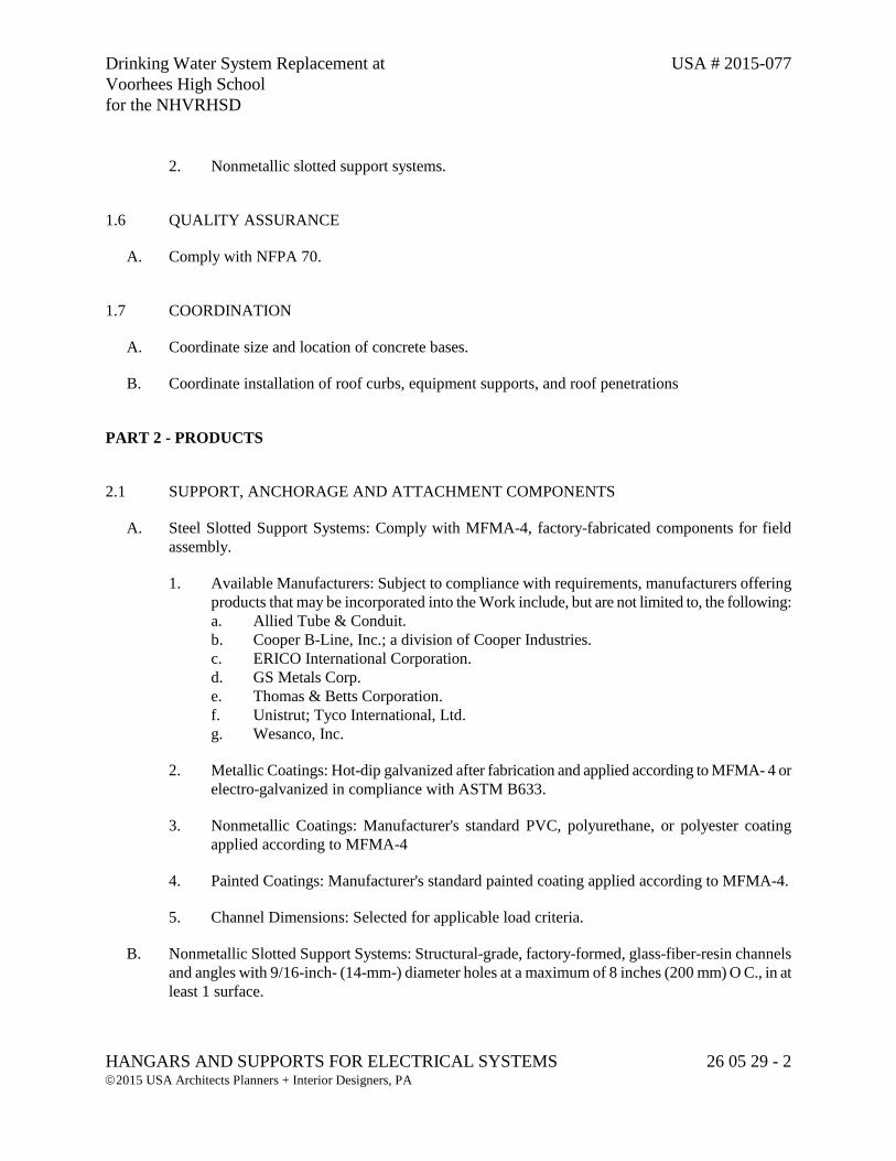
Drinking Water System Replacement at USA # 2015-077 Voorhees High School for the NHVRHSD
HANGARS AND SUPPORTS FOR ELECTRICAL SYSTEMS 26 05 29 - 2 2015 USA Architects Planners + Interior Designers, PA
2. Nonmetallic slotted support systems.
1.6 QUALITY ASSURANCE
A. Comply with NFPA 70.
1.7 COORDINATION
A. Coordinate size and location of concrete bases.
B. Coordinate installation of roof curbs, equipment supports, and roof penetrations
PART 2 - PRODUCTS
2.1 SUPPORT, ANCHORAGE AND ATTACHMENT COMPONENTS
A. Steel Slotted Support Systems: Comply with MFMA-4, factory-fabricated components for field assembly.
1. Available Manufacturers: Subject to compliance with requirements, manufacturers offering products that may be incorporated into the Work include, but are not limited to, the following: a. Allied Tube & Conduit. b. Cooper B-Line, Inc.; a division of Cooper Industries. c. ERICO International Corporation. d. GS Metals Corp. e. Thomas & Betts Corporation. f. Unistrut; Tyco International, Ltd. g. Wesanco, Inc.
2. Metallic Coatings: Hot-dip galvanized after fabrication and applied according to MFMA- 4 or electro-galvanized in compliance with ASTM B633.
3. Nonmetallic Coatings: Manufacturer's standard PVC, polyurethane, or polyester coating applied according to MFMA-4
4. Painted Coatings: Manufacturer's standard painted coating applied according to MFMA-4.
5. Channel Dimensions: Selected for applicable load criteria.
B. Nonmetallic Slotted Support Systems: Structural-grade, factory-formed, glass-fiber-resin channels and angles with 9/16-inch- (14-mm-) diameter holes at a maximum of 8 inches (200 mm) O C., in at least 1 surface.
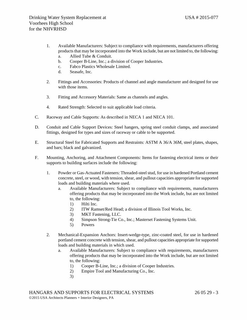
Drinking Water System Replacement at USA # 2015-077 Voorhees High School for the NHVRHSD
HANGARS AND SUPPORTS FOR ELECTRICAL SYSTEMS 26 05 29 - 3 2015 USA Architects Planners + Interior Designers, PA
1. Available Manufacturers: Subject to compliance with requirements, manufacturers offering products that may be incorporated into the Work include, but are not limited to, the following: a. Allied Tube & Conduit. b. Cooper B-Line, Inc.; a division of Cooper Industries. c. Fabco Plastics Wholesale Limited. d. Seasafe, Inc.
2. Fittings and Accessories: Products of channel and angle manufacturer and designed for use with those items.
3. Fitting and Accessory Materials: Same as channels and angles.
4. Rated Strength: Selected to suit applicable load criteria.
C. Raceway and Cable Supports: As described in NECA 1 and NECA 101.
D. Conduit and Cable Support Devices: Steel hangers, spring steel conduit clamps, and associated fittings, designed for types and sizes of raceway or cable to be supported.
E. Structural Steel for Fabricated Supports and Restraints: ASTM A 36/A 36M, steel plates, shapes, and bars; black and galvanized.
F. Mounting, Anchoring, and Attachment Components: Items for fastening electrical items or their supports to building surfaces include the following:
1. Powder or Gas-Actuated Fasteners: Threaded-steel stud, for use in hardened Portland cement concrete, steel, or wood, with tension, shear, and pullout capacities appropriate for supported loads and building materials where used. a. Available Manufacturers: Subject to compliance with requirements, manufacturers
offering products that may be incorporated into the Work include, but are not limited to, the following: 1) Hilti Inc. 2) ITW Ramset/Red Head; a division of Illinois Tool Works, Inc. 3) MKT Fastening, LLC. 4) Simpson Strong-Tie Co., Inc.; Masterset Fastening Systems Unit. 5) Powers
2. Mechanical-Expansion Anchors: Insert-wedge-type, zinc-coated steel, for use in hardened portland cement concrete with tension, shear, and pullout capacities appropriate for supported loads and building materials in which used. a. Available Manufacturers: Subject to compliance with requirements, manufacturers
offering products that may be incorporated into the Work include, but are not limited to, the following: 1) Cooper B-Line, Inc.; a division of Cooper Industries. 2) Empire Tool and Manufacturing Co., Inc. 3)
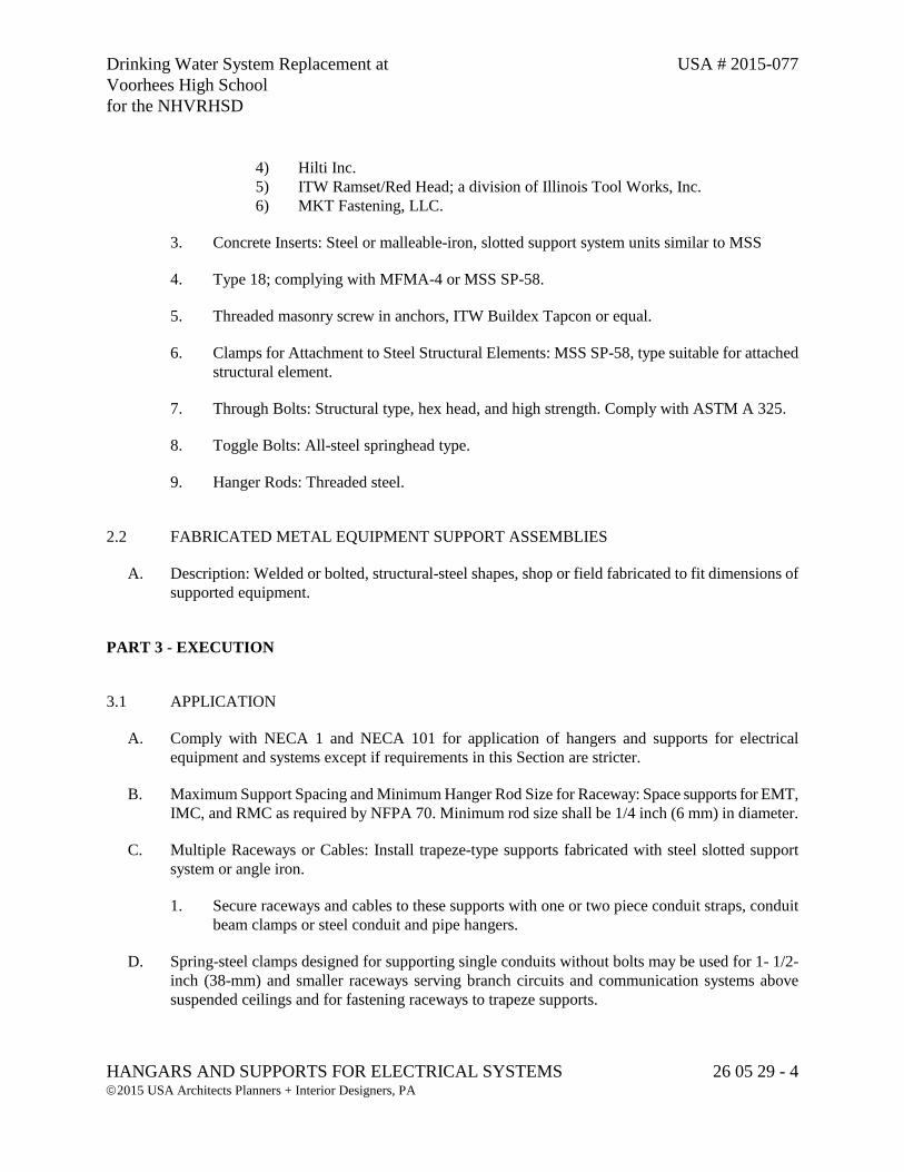
Drinking Water System Replacement at USA # 2015-077 Voorhees High School for the NHVRHSD
HANGARS AND SUPPORTS FOR ELECTRICAL SYSTEMS 26 05 29 - 4 2015 USA Architects Planners + Interior Designers, PA
4) Hilti Inc. 5) ITW Ramset/Red Head; a division of Illinois Tool Works, Inc. 6) MKT Fastening, LLC.
3. Concrete Inserts: Steel or malleable-iron, slotted support system units similar to MSS
4. Type 18; complying with MFMA-4 or MSS SP-58.
5. Threaded masonry screw in anchors, ITW Buildex Tapcon or equal.
6. Clamps for Attachment to Steel Structural Elements: MSS SP-58, type suitable for attached structural element.
7. Through Bolts: Structural type, hex head, and high strength. Comply with ASTM A 325.
8. Toggle Bolts: All-steel springhead type.
9. Hanger Rods: Threaded steel.
2.2 FABRICATED METAL EQUIPMENT SUPPORT ASSEMBLIES
A. Description: Welded or bolted, structural-steel shapes, shop or field fabricated to fit dimensions of supported equipment.
PART 3 - EXECUTION
3.1 APPLICATION
A. Comply with NECA 1 and NECA 101 for application of hangers and supports for electrical equipment and systems except if requirements in this Section are stricter.
B. Maximum Support Spacing and Minimum Hanger Rod Size for Raceway: Space supports for EMT, IMC, and RMC as required by NFPA 70. Minimum rod size shall be 1/4 inch (6 mm) in diameter.
C. Multiple Raceways or Cables: Install trapeze-type supports fabricated with steel slotted support system or angle iron.
1. Secure raceways and cables to these supports with one or two piece conduit straps, conduit beam clamps or steel conduit and pipe hangers.
D. Spring-steel clamps designed for supporting single conduits without bolts may be used for 1- 1/2-inch (38-mm) and smaller raceways serving branch circuits and communication systems above suspended ceilings and for fastening raceways to trapeze supports.
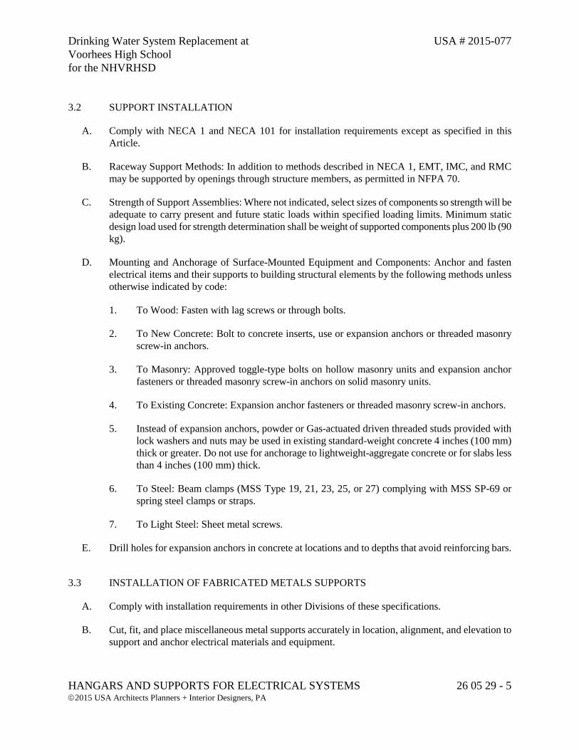
Drinking Water System Replacement at USA # 2015-077 Voorhees High School for the NHVRHSD
HANGARS AND SUPPORTS FOR ELECTRICAL SYSTEMS 26 05 29 - 5 2015 USA Architects Planners + Interior Designers, PA
3.2 SUPPORT INSTALLATION
A. Comply with NECA 1 and NECA 101 for installation requirements except as specified in this Article.
B. Raceway Support Methods: In addition to methods described in NECA 1, EMT, IMC, and RMC may be supported by openings through structure members, as permitted in NFPA 70.
C. Strength of Support Assemblies: Where not indicated, select sizes of components so strength will be adequate to carry present and future static loads within specified loading limits. Minimum static design load used for strength determination shall be weight of supported components plus 200 lb (90 kg).
D. Mounting and Anchorage of Surface-Mounted Equipment and Components: Anchor and fasten electrical items and their supports to building structural elements by the following methods unless otherwise indicated by code:
1. To Wood: Fasten with lag screws or through bolts.
2. To New Concrete: Bolt to concrete inserts, use or expansion anchors or threaded masonry screw-in anchors.
3. To Masonry: Approved toggle-type bolts on hollow masonry units and expansion anchor fasteners or threaded masonry screw-in anchors on solid masonry units.
4. To Existing Concrete: Expansion anchor fasteners or threaded masonry screw-in anchors.
5. Instead of expansion anchors, powder or Gas-actuated driven threaded studs provided with lock washers and nuts may be used in existing standard-weight concrete 4 inches (100 mm) thick or greater. Do not use for anchorage to lightweight-aggregate concrete or for slabs less than 4 inches (100 mm) thick.
6. To Steel: Beam clamps (MSS Type 19, 21, 23, 25, or 27) complying with MSS SP-69 or spring steel clamps or straps.
7. To Light Steel: Sheet metal screws.
E. Drill holes for expansion anchors in concrete at locations and to depths that avoid reinforcing bars.
3.3 INSTALLATION OF FABRICATED METALS SUPPORTS
A. Comply with installation requirements in other Divisions of these specifications.
B. Cut, fit, and place miscellaneous metal supports accurately in location, alignment, and elevation to support and anchor electrical materials and equipment.
Drinking Water System Replacement at USA # 2015-077 Voorhees High School for the NHVRHSD
HANGARS AND SUPPORTS FOR ELECTRICAL SYSTEMS 26 05 29 - 6 2015 USA Architects Planners + Interior Designers, PA
C. Field Welding: Comply with AWS D1.1/D1.1M.
3.4 CONCRETE BASES
A. Construct concrete bases of dimensions indicated but not less than 4 inches (100 mm) larger in both directions than supported unit, and so anchors will be a minimum of 10 bolt diameters from edge of the base.
B. Use 3000-psi, 28-day compressive-strength concrete.
C. Anchor equipment to concrete base.
1. Place and secure anchorage devices. Use supported equipment manufacturer's setting drawings, templates, diagrams, instructions, and directions furnished with items to be embedded.
2. Install anchor bolts to elevations required for proper attachment to supported equipment.
3. Install anchor bolts according to anchor-bolt manufacturer's written instructions.
3.5 PAINTING
A. Touchup: Clean field welds and abraded areas of shop paint. Paint exposed areas immediately after erecting hangers and supports. Use same materials as used for shop painting. Comply with SSPC-PA 1 requirements for touching up field-painted surfaces.
1. Apply paint by brush or spray to provide minimum dry film thickness of 2.0 mils (0.05 mm).
B. Galvanized Surfaces: Clean welds, bolted connections, and abraded areas and apply galvanizing-repair paint to comply with ASTM A 780.
PART 4 - PAYMENT
4.1 QUANTITY AND PAYMENT
A. No separate payment shall be made for this section. The cost shall be included within the various items bid in the Proposal.
END OF SECTION 26 05 29

Drinking Water System Replacement at USA # 2015-077 Voorhees High School for the NHVRHSD
RACEWAY AND BOXES FOR ELECTRICAL SYSTEMS 26 05 33 - 1 2015 USA Architects Planners + Interior Designers, PA
SECTION 26 05 33 – RACEWAY AND BOXES FOR ELECTRICAL SYSTEMS
PART 1 - GENERAL
1.1 RELATED DOCUMENTS
A. Drawings and general provisions of the Contract, including General and Supplementary Conditions and Division 01 Specification Sections, apply to this Section.
1.2 SUMMARY
A. This Section includes raceways, fittings, boxes, enclosures, and cabinets for electrical wiring.
1.3 DEFINITIONS
A. EMT: Electrical metallic tubing.
B. ENT: Electrical nonmetallic tubing.
C. FMC: Flexible metal conduit.
D. IMC: Intermediate metal conduit.
E. LFMC: Liquidtight flexible metal conduit.
F. LFNC: Liquidtight flexible nonmetallic conduit.
G. RNC: Rigid nonmetallic conduit.
1.4 SUBMITTALS
A. Product Data: For raceways, wireways and fittings, floor boxes, hinged-cover enclosures, and cabinets.
1.5 QUALITY ASSURANCE
A. Comply with NFPA 70.
Drinking Water System Replacement at USA # 2015-077 Voorhees High School for the NHVRHSD
RACEWAY AND BOXES FOR ELECTRICAL SYSTEMS 26 05 33 - 2 2015 USA Architects Planners + Interior Designers, PA
PART 2 - PRODUCTS
2.1 METAL CONDUIT AND TUBING.
A. Available Manufacturers: Subject to compliance with requirements, manufacturers offering products that may be incorporated into the Work include, but are not limited to, the following: 1. AFC Cable Systems, Inc. 2. Alflex Inc. 3. Allied Tube & Conduit; a Tyco International Ltd. Co. 4. Anamet Electrical, Inc.; Anaconda Metal Hose. 5. Electri-Flex Co. 6. Manhattan/CDT/Cole-Flex. 7. Maverick Tube Corporation. 8. O-Z Gedney; a unit of General Signal. 9. Wheatland Tube Company. 10. Southwire 11. Thomas & Betts 12. Cooper 13. American Fittings Corporation
B. Rigid Steel Conduit: ANSI C80.1.
C. Aluminum Rigid Conduit: ANSI C80.5.
D. IMC: ANSI C80.6.
E. PVC-Coated Steel Conduit: PVC-coated rigid steel conduit IMC. 1. Comply with NEMA RN 1. 2. Coating Thickness: 0.040 inch (1 mm), minimum.
F. EMT: ANSI C80.3.
G. FMC: Zinc-coated steel or aluminum.
H. LFMC: Flexible steel conduit with PVC jacket.
I. Fittings for Conduit (Including all Types and Flexible and Liquidtight), EMT, and Cable: NEMA FB 1; listed for type and size raceway with which used, and for application and environment in which installed. 1. Conduit Fittings for Hazardous (Classified) Locations: Comply with UL 886. 2. Fittings for EMT: Steel or die-cast, compression type. Set screw type fittings are not
acceptable.
2.2 NONMETALLIC CONDUIT AND TUBING
Drinking Water System Replacement at USA # 2015-077 Voorhees High School for the NHVRHSD
RACEWAY AND BOXES FOR ELECTRICAL SYSTEMS 26 05 33 - 3 2015 USA Architects Planners + Interior Designers, PA
A. Available Manufacturers: Subject to compliance with requirements, manufacturers offering products that may be incorporated into the Work include, but are not limited to, the following: 1. AFC Cable Systems, Inc. 2. Anamet Electrical, Inc.; Anaconda Metal Hose. 3. Arnco Corporation. 4. CANTEX Inc. 5. CertainTeed Corp.; Pipe & Plastics Group. 6. Condux International, Inc. 7. ElecSYS, Inc. 8. Electri-Flex Co. 9. Lamson & Sessions; Carlon Electrical Products. 10. Manhattan/CDT/Cole-Flex. 11. RACO; a Hubbell Company. 12. Thomas & Betts Corporation. 13. National Pipe and Plastics, Inc.
B. ENT: NEMA TC 13.
C. RNC: NEMA TC 2, Type EPC-40-PVC, unless otherwise indicated.
D. LFNC: UL 1660.
E. Fittings for ENT and RNC: NEMA TC 3; match to conduit or tubing type and material.
F. Fittings for LFNC: UL 514B.
2.3 METAL WIREWAYS
A. Available Manufacturers: Subject to compliance with requirements, manufacturers offering products that may be incorporated into the Work include, but are not limited to, the following: 1. Cooper B-Line, Inc. 2. Hoffman. 3. Sqaure D; Schneider Electric. 4. Austin
B. Description: Sheet metal sized and shaped as indicated, NEMA 250, Type 1 or 3R, unless otherwise indicated.
C. Fittings and Accessories: Include couplings, offsets, elbows, expansion joints, adapters, holddown straps, end caps, and other fittings to match and mate with wireways as required for complete system.
D. Wireway Covers: Screw-cover type.
Drinking Water System Replacement at USA # 2015-077 Voorhees High School for the NHVRHSD
RACEWAY AND BOXES FOR ELECTRICAL SYSTEMS 26 05 33 - 4 2015 USA Architects Planners + Interior Designers, PA
E. Finish: Manufacturer's standard enamel finish.
2.4 BOXES, ENCLOSURES AND CABINETS
A. Available Manufacturers: Subject to compliance with requirements, manufacturers offering products that may be incorporated into the Work include, but are not limited to, the following: 1. Cooper Crouse-Hinds; Div. of Cooper Industries, Inc. 2. EGS/Appleton Electric. 3. Erickson Electrical Equipment Company. 4. Hoffman. 5. Hubbell Incorporated; Killark Electric Manufacturing Co. Division. 6. O-Z/Gedney; a unit of General Signal. 7. RACO; a Hubbell Company. 8. Robroy Industries, Inc.; Enclosure Division. 9. Scott Fetzer Co.; Adalet Division. 10. Spring City Electrical Manufacturing Company. 11. Thomas & Betts Corporation. 12. Walker Systems, Inc.; Wiremold Company (The). 13. Woodhead, Daniel Company; Woodhead Industries, Inc. Subsidiary. 14. Wiremold
B. Sheet Metal Outlet and Device Boxes: NEMA OS 1.
C. Cast-Metal Outlet and Device Boxes: NEMA FB 1, ferrous alloy, Type FD, with gasketed cover.
D. Nonmetallic Outlet and Device Boxes: NEMA OS 2.
E. Metal Floor Boxes: Cast or sheet metal, fully adjustable, rectangular.
F. Nonmetallic Floor Boxes: Nonadjustable, round.
G. Small Sheet Metal Pull and Junction Boxes under 100 cubic inches: NEMA OS 1.
H. Cast-Metal Access, Pull, and Junction Boxes: NEMA FB 1, galvanized, cast iron with gasketed cover.
I. Hinged-Cover Enclosures: NEMA 250, Type 1, with butt-hinge cover with flush latch, unless otherwise indicated. 1. Metal Enclosures: Steel, finished inside and out with manufacturer's standard enamel. 2. Enclosures used outdoors shall be NEMA 4X made of Stainless Steel. 3. Enclosures applied in corrosive areas such as the Solids building shall be NEMA 4X made of
Stainless Steel.
J. Cabinets:
Drinking Water System Replacement at USA # 2015-077 Voorhees High School for the NHVRHSD
RACEWAY AND BOXES FOR ELECTRICAL SYSTEMS 26 05 33 - 5 2015 USA Architects Planners + Interior Designers, PA
1. NEMA 250, Type 1, galvanized-steel box with removable interior panel and removable front, finished inside and out with manufacturer's standard enamel.
2. Hinged door in front cover with flush latch and concealed hinge. 3. Metal barriers to separate wiring of different systems and voltage. 4. Accessory feet where required for freestanding equipment. 5. Cabinets applied outdoors or in corrosive environments shall be NEMA 4X Stainless Steel.
PART 3 - EXECUTION
3.1 RACEWAY APPLICATION
A. Outdoors: Apply raceway products as specified below, unless otherwise indicated:
1. Exposed Conduit: Rigid steel conduit.
2. Concealed Conduit, Aboveground: Rigid steel conduit.
3. Underground Conduit: RNC, Type EPC-80-PVC, (Extra heavy wall) direct buried.
4. Underground Conduit encased in reinforced concrete: RNC, Type EPC -40-PVC.
5. Connection to Vibrating Equipment (Including Transformers and Hydraulic, Pneumatic, Electric Solenoid, or Motor-Driven Equipment): LFMC.
6. Boxes and Enclosures, Aboveground: NEMA 250, Type 3R.
7. Application of Handholes and Boxes for Underground Wiring: a. Handholes and Pull Boxes in Driveway, Parking Lot, and Off-Roadway Locations,
Subject to Occasional, Nondeliberate Loading by Heavy Vehicles: Polymer concrete, SCTE 77, Tier 15 structural load rating.
b. Handholes and Pull Boxes in Sidewalk and Similar Applications with a Safety Factor for Nondeliberate Loading by Vehicles: Polymer-concrete units, SCTE 77, Tier 8 structural load rating.
c. Handholes and Pull Boxes Subject to Light-Duty Pedestrian Traffic Only: Fiberglass-reinforced polyester resin, structurally tested according to SCTE 77 with 3000-lbf (13 345-N) vertical loading.
d. Provide grounding inspection box, Harger 360PP or equal.
B. Comply with the following indoor applications, unless otherwise indicated:
1. Within Booster Station, Exposed, Not Subject to Physical Damage: PVC Schedule 80. Within Booster Station, Exposed, subject to mechanical damage, RMC.
2. Within School Building, raceways installed in dropped ceilings, EMT. Within School Building, all Exposed raceways, RMC.
Drinking Water System Replacement at USA # 2015-077 Voorhees High School for the NHVRHSD
RACEWAY AND BOXES FOR ELECTRICAL SYSTEMS 26 05 33 - 6 2015 USA Architects Planners + Interior Designers, PA
3. Connection to Vibrating Equipment (Including Transformers and Hydraulic, Pneumatic, Electric Solenoid or Motor-Driven Equipment): LFMC.
4. Boxes and Enclosures: NEMA 250, Type 1, except use NEMA 250, Type 4X in damp, wet, and corrosive locations.
C. Minimum Raceway Size Indoors and Outdoors Above Ground: 3/4-inch trade size.
D. Minimum Raceway Size Outdoors, Underground: 1 inch trade size.
E. Raceway Fittings: Compatible with raceways and suitable for use and location.
F. Install nonferrous conduit or tubing for circuits operating above 60 Hz. Where aluminum raceways are installed for such circuits and pass through concrete, install in nonmetallic sleeve.
G. Apply bituminous paint to all metallic conduits in contact with concrete.
H. Do not install aluminum conduits in contact with concrete.
3.2 INSTALLATION
A. Comply with NECA 1 for installation requirements applicable to products specified in Part 2 except where requirements on Drawings or in this Article are stricter.
B. Keep raceways at least 6 inches (150 mm) away from parallel runs of flues and steam or hot water pipes.
C. Complete raceway installation before starting conductor installation.
D. Support raceways as specified in Division 26 Section "Hangers and Supports for Electrical Systems."
E. Arrange stub-ups so curved portions of bends are not visible above the finished slab.
F. Install no more than the equivalent of four 90-degree bends in any conduit run except for communications conduits, for which fewer bends are allowed.
G. Where possible, conceal conduit within finished walls, ceilings, and floors, unless otherwise indicated.
H. Raceways Embedded in Slabs:
1. Run conduit larger than 1-inch (27-mm) trade size, parallel or at right angles to main reinforcement. Where at right angles to reinforcement, place conduit close to slab support.
2. Arrange raceways to cross building expansion joints at right angles with expansion fittings.
Drinking Water System Replacement at USA # 2015-077 Voorhees High School for the NHVRHSD
RACEWAY AND BOXES FOR ELECTRICAL SYSTEMS 26 05 33 - 7 2015 USA Architects Planners + Interior Designers, PA
3. Raceway Terminations at Locations Subject to Moisture or Vibration: Use insulating bushings to protect conductors, including conductors smaller than No. 4 AWG.
I. Install pull wires in empty raceways. Use polypropylene or monofilament plastic line with not less than 200-lb (90-kg) tensile strength. Leave at least 12 inches (300 mm) of slack at each end of pull wire.
J. Flexible Conduit Connections: Use maximum of 72 inches (1830 mm) of flexible conduit for recessed and semirecessed lighting fixtures, equipment subject to vibration, noise transmission, or movement; and for transformers and motors.
K. Use LFMC in damp or wet locations subject to severe physical damage.
L. Use LFMC or LFNC in damp or wet locations not subject to severe physical damage.
M. Recessed Boxes in Masonry Walls: Saw-cut opening for box in center of cell of masonry block, and install box flush with surface of wall.
N. Set metal floor boxes level and flush with finished floor surface.
O. Provide expansion fittings in conduits 80 feet in length and greater.
P. Set nonmetallic floor boxes level. Trim after installation to fit flush with finished floor surface.
3.3 PROTECTION
A. Provide final protection and maintain conditions that ensure coatings, finishes, and cabinets are without damage or deterioration at time of Substantial Completion.
1. Repair damage to galvanized finishes with zinc-rich paint recommended by manufacturer.
2. Repair damage to PVC or paint finishes with matching touchup coating recommended by manufacturer.
PART 4 - PAYMENT
4.1 QUANTITY AND PAYMENT
A. No separate payment shall be made for this section. The cost shall be included within the various items bid in the Proposal.
END OF SECTION 26 05 33

Drinking Water System Replacement at USA # 2015-077 Voorhees High School for the NHVRHSD
IDENTIFICATION FOR ELECTRICAL SYSTEMS 26 05 53 - 1 2015 USA Architects Planners + Interior Designers, PA
SECTION 26 05 53 – IDENTIFICATION FOR ELECTRICAL SYSTEMS
PART 1 - GENERAL
1.1 SECTION INCLUDES
A. Nameplates and labels.
B. Wire and cable markers.
C. Conduit markers.
D. Pull and Junction Box labels.
1.2 RELATED SECTIONS
A. Section 26 05 00 – Common Work Results for Electrical.
1.3 REFERENCES
A. Materials and workmanship shall conform to the latest issue of all industry standards, publications, or regulations referenced in this section and with the following references as applicable. Refer to Section 26 05 00 for listing of issuing organizations or agencies.
1. NFPA 70 - National Electrical Code.
1.4 SUBMITTALS
A. Product Data: Provide catalog data for nameplates, labels, and markers.
B. Include schedule for nameplates, tape(s), and labels.
1.5 REGULATORY REQUIREMENTS
A. Conform to requirements of NFPA 70.
Drinking Water System Replacement at USA # 2015-077 Voorhees High School for the NHVRHSD
IDENTIFICATION FOR ELECTRICAL SYSTEMS 26 05 53 - 2 2015 USA Architects Planners + Interior Designers, PA
PART 2 - PRODUCTS
2.1 MATERIALS
A. Nameplates: Engraved multiple layer laminated plastic, white letters on a black background.
B. Tape Labels: Embossed adhesive tape, with 3/16 inch white letters on black background.
C. Wire and Cable Markers: Cloth markers, split sleeve or tubing type.
D. Pretensioned Wraparound Plastic Sleeves: Flexible, preprinted, color coded, acrylic band sized to suit the diameter of the raceway it identifies. Installed to remain in place by pretensioned gripping action when placed in position.
2.2 NAMEPLATES AND SIGNS
A. Safety Signs: comply with 29 CFR, Chapter XVII, Part 1910.145.
PART 3 - EXECUTION
3.1 INSTALLATION
A. Degrease and clean surfaces to receive nameplates and tape labels.
B. Install nameplates and tape labels parallel to equipment lines.
C. Secure nameplates to equipment fronts using screws, rivets, or adhesive. Secure nameplate to inside face of recessed panelboard doors in finished locations.
3.2 WIRE MARKERS
A. Description: Cloth, tape, split sleeve, or tubing type wire markers.
B. Locations: Each conductor at panelboard gutters, pull boxes, junction boxes, and each load connection.
C. Legend:
1. Power and Lighting Circuits: Branch circuit or feeder number indicated on drawings.
2. Control Circuits: Control wire number indicated on shop drawings.
Drinking Water System Replacement at USA # 2015-077 Voorhees High School for the NHVRHSD
IDENTIFICATION FOR ELECTRICAL SYSTEMS 26 05 53 - 3 2015 USA Architects Planners + Interior Designers, PA
3.3 COLOR CODING OF PHASE CONDUCTORS
A. Use the following colors for service, feeder and branch-circuit phase conductors:
1. 208/120 Volt Conductors: a. Phase A: Black b. Phase B: Red c. Phase C: Blue d. Neutral: White
2. 120/240 Volt Conductors: a. Phase A: Black b. Phase B: Orange c. Phase C: Red d. Neutral: White
3. 480/277 Volt Conductors: a. Phase A: Yellow b. Phase B: Brown c. Phase C: Orange or Purple d. Neutral: White
B. Use factory applied color (insulation). Field applied color coding methods may be used if approved by Engineer.
1. Field applied methods may include application of pressure sensitive plastic tape in half –lapped turns for a distance of 6 inches minimum from terminations or where splices are made.
2. Colored cable ties in groups of three (3) ties of a specific color applied to each wire starting no more than three (3) inches from termination and spaced three (3) inches apart.
3.4 RACEWAY LABELING
A. Label raceways by circuit number or type as required by Engineer.
3.5 NAMEPLATE ENGRAVING SCHEDULE
A. Provide nameplates of minimum letter height listed below:
1. Panelboards, Switchboards and Motor Control Centers: 1/4 inch; identify equipment designation. 1/8 inch; identify voltage rating and source.
2. Individual Circuit Breakers, Switches, and Motor Starters (including Variable Speed Drives) in Panelboards, Switchboards, and Motor Control Centers: 1/8 inch; identify circuit and load served, including location.
Drinking Water System Replacement at USA # 2015-077 Voorhees High School for the NHVRHSD
IDENTIFICATION FOR ELECTRICAL SYSTEMS 26 05 53 - 4 2015 USA Architects Planners + Interior Designers, PA
3. Individual Circuit Breakers, Enclosed Switches, and Motor Starters: 1/8 inch; identify load served.
4. Transformers: 1/4 inch; identify equipment designation. 1/8 inch; identify primary and secondary voltages, primary source, and secondary load and location.
5. Device Plates: Where more than two wall switches are installed in ganged outlet assemblies: 1/8 inch; identify type of lighting controlled. On receptacle faceplates: 1/8 inch; identify panel and circuit number serving the device.
PART 4 - PAYMENT
4.1 QUANTITY AND PAYMENT
A. No separate payment shall be made for this section. The cost shall be included within the various items bid in the Proposal.
END OF SECTION 26 05 53
Drinking Water System Replacement at USA # 2015-077 Voorhees High School for the NHVRHSD
ARC FLASH HAZARD ANALYSIS/SHORT-CIRCUIT/COORDINATION STUDY 26 05 73 - 1 2015 USA Architects Planners + Interior Designers, PA
SECTION 26 05 73 – ARC FLASH HAZARD ANALYSIS/SHORT-CIRCUIT/COORDINATION STUDY
PART 1 - GENERAL
1.1 SCOPE
A. The Owner shall be furnished short-circuit and protective device coordination studies as prepared by Square D Engineering Services or approved equal.
B. Provide an Arc Flash Hazard Analysis Study per the requirements set forth in the current issue of NFPA 70E -Standard for Electrical Safety in the Workplace. The arc flash hazard analysis shall be performed according to the IEEE Standard 1584 – 2002, the IEEE Guide for Performing Arc-Flash Calculations.
C. The scope of the studies shall include all electrical equipment supplied under this Contract.
1.2 RELATED SECTIONS
A. Contract plans and general provisions of the Contract.
1.3 REFERENCES
A. Institute of Electrical and Electronics Engineers, Inc. (IEEE):
1. IEEE 141 – Recommended Practice for Electric Power Distribution and Coordination of Industrial and Commercial Power Systems
2. IEEE 242 – Recommended Practice for Protection and Coordination of Industrial and Commercial Power Systems
3. IEEE 399 – Recommended Practice for Industrial and Commercial Power System Analysis
4. IEEE 241 – Recommended Practice for Electric Power Systems in Commercial Buildings
5. IEEE 1015 – Recommended Practice for Applying Low-Voltage Circuit Breakers Used in Industrial and Commercial Power Systems.
6. IEEE 1584 -Guide for Performing Arc-Flash Hazard Calculations
Drinking Water System Replacement at USA # 2015-077 Voorhees High School for the NHVRHSD
ARC FLASH HAZARD ANALYSIS/SHORT-CIRCUIT/COORDINATION STUDY 26 05 73 - 2 2015 USA Architects Planners + Interior Designers, PA
B. American National Standards Institute (ANSI):
1. ANSI C57.12.00 – Standard General Requirements for Liquid-Immersed Distribution, Power, and Regulating Transformers
2. ANSI C37.13 – Standard for Low Voltage AC Power Circuit Breakers Used in Enclosures
3. ANSI C37.010 – Standard Application Guide for AC High Voltage Circuit Breakers Rated on a Symmetrical Current Basis
4. ANSI C 37.41 – Standard Design Tests for High Voltage Fuses, Distribution Enclosed Single-Pole Air Switches, Fuse Disconnecting Switches and Accessories.
C. The National Fire Protection Association (NFPA)
1. NFPA 70 -National Electrical Code, latest edition
2. NFPA 70E – Standard for Electrical Safety in the Workplace
1.4 SUBMITTALS FOR REVIEW/APPROVAL
A. The studies shall be submitted to the Engineer for review and approval prior to final completion.
1.5 FINAL SUBMITTALS
A. The results of the short-circuit, protective device coordination and arc flash hazard analysis studies shall be summarized in a final report. A minimum of four (4) bound copies of the complete final report shall be submitted. Electronic PDF copies of the report shall be provided upon request.
B. The report shall include the following sections:
1. Executive Summary including Introduction, Scope of Work and Results/Recommendations.
2. Short-Circuit Methodology Analysis Results and Recommendations
3. Short-Circuit Device Evaluation Table
4. Protective Device Coordination Methodology Analysis Results and Recommendations
5. Protective Device Settings Table
6. Time-Current Coordination Graphs and Recommendations
7. Arc Flash Hazard Methodology Analysis Results and Recommendations including the details of the incident energy and flash protection boundary calculations, along with Arc Flash
Drinking Water System Replacement at USA # 2015-077 Voorhees High School for the NHVRHSD
ARC FLASH HAZARD ANALYSIS/SHORT-CIRCUIT/COORDINATION STUDY 26 05 73 - 3 2015 USA Architects Planners + Interior Designers, PA
boundary distances, working distances, Incident Energy levels and Personal Protection Equipment levels.
8. Arc Flash Labeling section showing types of labels to be provided. This Section will contain descriptive information as well as typical label images.
9. One-line system diagram that shall be computer generated and will clearly identify individual equipment buses, bus numbers used in the short-circuit analysis, cable and bus connections between the equipment, calculated maximum short-circuit current at each bus location, device numbers used in the time-current coordination analysis, and other information pertinent to the computer analysis.
1.6 QUALIFICATIONS
A. The short-circuit, protective device coordination and arc flash hazard analysis studies shall be conducted under the responsible charge and approval of a Registered Professional Engineer skilled in performing and interpreting the power system studies.
B. The Registered Professional Electrical Engineer shall be an employee of the approved engineering firm.
C. The Registered Professional Electrical Engineer shall have a minimum of five (5) years of experience in performing power system studies.
1.7 COMPUTER ANALYSIS SOFTWARE
A. The studies shall be performed using SKM Systems Analysis Power*Tools for Windows (PTW) software program or Engineer approved equal.
PART 2 - PRODUCTS
2.1 STUDIES
A. Furnish an Arc Flash Hazard Analysis Study per NFPA 70E -Standard for Electrical Safety in the Workplace, reference Article 130.3 and Annex D. This study shall also include short-circuit and protective device coordination studies.
2.2 DATA COLLECTION
A. Field data collection shall be performed by a Technician, qualified (as defined by NFPA 70E – 2004) to ensure accurate equipment modeling.
Drinking Water System Replacement at USA # 2015-077 Voorhees High School for the NHVRHSD
ARC FLASH HAZARD ANALYSIS/SHORT-CIRCUIT/COORDINATION STUDY 26 05 73 - 4 2015 USA Architects Planners + Interior Designers, PA
B. The Engineer will visually inspect to verify the equipment ratings, conductor ratings and overcurrent device data by removing panels, covers and doors where required to document the necessary data used in the analysis. The Engineer can perform these inspections with the equipment energized provided the incident energy values are less than 40cal/cm², greater values or unusual site conditions will require an equipment shutdown so the equipment can be inspected de-energized.
C. The Owner shall provide qualified personnel to show the Engineer/Technician the equipment location and to open all equipment doors, locks, etc. necessary to collect nameplate data.
D. The service provider shall verify the Owner’s one-line drawings and provide marked corrections where discrepancies are found.
E. Data collection shall begin downstream from the utility service and continue down through the Owner’s electrical distribution system as defined under scope of work. The study shall not include any single phase AC circuits or DC distribution systems as these types of circuits and systems are excluded from IEEE 1584-2002 Arc Flash calculation guidelines. The study will not include equipment rated 240 volts or less per NFPA 70E, when supplied by a single transformer rated less than 125kVA.
F. Square D shall obtain from the utility the minimum, normal, and maximum operating service voltage levels, three-phase short circuit MVA and X/R ratio, as well as line-to-ground short circuit MVA and X/R ratio at the point of connection as shown on the drawings.
2.3 SHORT-CIRCUIT ANALYSIS
A. Transformer design impedances shall be used when test impedances are not available.
B. Provide the following:
1. Calculation methods and assumptions
2. Selected base per unit quantities
3. One-line diagram of the system being evaluated that clearly identifies individual equipment buses, bus numbers used in the short-circuit analysis, cable and bus connections between the equipment, calculated maximum short-circuit current at each bus location and other information pertinent to the computer analysis
4. The study shall include input circuit data including electric utility system characteristics, source impedance data, conductor lengths, number of conductors per phase, conductor impedance values, insulation types, transformer impedances and X/R ratios, motor contributions, and other circuit information as related to the short-circuit calculations.
5. Tabulations of calculated quantities including short-circuit currents, X/R ratios, equipment short-circuit interrupting or withstand current ratings and notes regarding adequacy or inadequacy of the equipment rating.
Drinking Water System Replacement at USA # 2015-077 Voorhees High School for the NHVRHSD
ARC FLASH HAZARD ANALYSIS/SHORT-CIRCUIT/COORDINATION STUDY 26 05 73 - 5 2015 USA Architects Planners + Interior Designers, PA
6. Results, conclusions, and recommendations. A comprehensive discussion section evaluating the adequacy or inadequacy of the equipment must be provided and include recommendations as appropriate for improvements to the system.
C. For solidly-grounded systems, provide a bolted line-to-ground fault current study for applicable buses as determined by the engineer performing the study.
D. Protective Device Evaluation:
1. Evaluate equipment and protective devices and compare to short circuit ratings
2. Adequacy of switchgear, motor control centers, and panelboard bus bars to withstand short-circuit stresses
3. Square D shall notify Owner in writing, of any circuit protective devices improperly rated for the calculated available fault current.
2.4 PROTECTIVE DEVICE TIME-CURRENT COORDINATION ANALYSIS
A. Protective device coordination time-current curves (TCC) shall be displayed on log-log scale graphs.
B. Include on each TCC graph, a complete title with descriptive device names.
C. Terminate device characteristic curves at a point reflecting maximum symmetrical or asymmetrical fault current to which the device is exposed.
D. Identify the device associated with each curve by manufacturer type, function, and, if applicable, tap, time delay, and instantaneous settings recommended.
E. Plot the following characteristics on the TCC graphs, where applicable:
1. Electric utility’s overcurrent protective device
2. Medium voltage equipment overcurrent relays
3. Medium and low voltage fuses including manufacturer’s minimum melt, total clearing, tolerance, and damage bands
4. Low voltage equipment circuit breaker trip devices, including manufacturer’s tolerance bands
5. Transformer full-load current, magnetizing inrush current, and ANSI through-fault protection curves
6. Medium voltage conductor damage curves
7. Ground fault protective devices, as applicable
Drinking Water System Replacement at USA # 2015-077 Voorhees High School for the NHVRHSD
ARC FLASH HAZARD ANALYSIS/SHORT-CIRCUIT/COORDINATION STUDY 26 05 73 - 6 2015 USA Architects Planners + Interior Designers, PA
8. Pertinent motor starting characteristics and motor damage points, where applicable
9. Pertinent generator short-circuit decrement curve and generator damage point
10. The largest feeder circuit breaker in each motor control center and applicable panelboard.
F. Provide adequate time margins between device characteristics such that selective operation is provided, while providing proper protection.
G. Provide the following:
1. A One-line diagram shall be provided which clearly identifies individual equipment buses, bus numbers, device identification numbers and the maximum available short-circuit current at each bus when known.
2. A sufficient number of log-log plots shall be provided to indicate the degree of system protection and coordination by displaying the time-current characteristics of series connected overcurrent devices and other pertinent system parameters.
3. Computer printouts shall accompany the log-log plots and will contain descriptions for each of the devices shown, settings of the adjustable devices, and device identification numbers to aid in locating the devices on the log-log plots and the system one-line diagram.
4. The study shall include a separate, tabular printout containing the recommended settings of all adjustable overcurrent protective devices, the equipment designation where the device is located, and the device number corresponding to the device on the system one-line diagram.
5. A discussion section which evaluates the degree of system protection and service continuity with overcurrent devices, along with recommendations as required for addressing system protection or device coordination deficiencies.
6. Notify the Owner in writing of any significant deficiencies in protection and/or coordination. Provide recommendations for improvements.
2.5 ARC FLASH HAZARD ANALYSIS
A. The arc flash hazard analysis shall be performed according to the IEEE 1584 equations that are presented in NFPA70E-2009, Annex D. The arc flash hazard analysis shall be performed in conjunction with the short-circuit analysis (Section 2.03) and the protective device time-current coordination analysis (Section 2.04)
B. The flash protection boundary and the incident energy shall be calculated at significant locations in the electrical distribution system (switchboards, switchgear, motor-control centers, panelboards, busway and splitters) where work could be performed on energized parts.
Drinking Water System Replacement at USA # 2015-077 Voorhees High School for the NHVRHSD
ARC FLASH HAZARD ANALYSIS/SHORT-CIRCUIT/COORDINATION STUDY 26 05 73 - 7 2015 USA Architects Planners + Interior Designers, PA
C. Circuits 240V or less fed by single transformer rated less than 125 kVA may be omitted from the computer model and will be assumed to have a hazard risk category 0 per NFPA 70E.
D. Working distances shall be based on IEEE 1584. The calculated arc flash protection boundary shall be determined using those working distances.
E. When appropriate, the short circuit calculations and the clearing times of the phase overcurrent devices will be retrieved from the short-circuit and coordination study model. Ground overcurrent relays should not be taken into consideration when determining the clearing time when performing incident energy calculations
F. The short-circuit calculations and the corresponding incident energy calculations for multiple system scenarios must be compared and the greatest incident energy must be uniquely reported for each equipment location in a single table. Calculations must be performed to represent the maximum and minimum contributions of fault current magnitude for normal and emergency operating conditions. The minimum calculation will assume that the utility contribution is at a minimum. Conversely, the maximum calculation will assume a maximum contribution from the utility. Calculations shall take into consideration the parallel operation of synchronous generators with the electric utility, where applicable as well as any stand-by generator applications.
The Arc-Flash Hazard Analysis shall be performed utilizing mutually agreed upon facility operational conditions, and the final report shall describe, when applicable, how these conditions differ from worst-case bolted fault conditions.
G. The incident energy calculations must consider the accumulation of energy over time when performing arc flash calculations on buses with multiple sources. Iterative calculations must take into account the changing current contributions, as the sources are interrupted or decremented with time. Fault contribution from motors should be decremented as follows:
1. Fault contribution from induction motors should not be considered beyond 5 cycles.
H. For each piece of ANSI rated equipment with an enclosed main device, two calculations shall be made. A calculation shall be made for the main cubicle, sides, or rear; and shall be based on a device located upstream of the equipment to clear the arcing fault. A second calculation shall be made for the front cubicles and shall be based on the equipment’s main device to clear the arcing fault. For all other non-ANSI rated equipment, only one calculation shall be required and it shall be based on a device located upstream of the equipment to clear the arcing fault.
I. When performing incident energy calculations on the line side of a main breaker (as required per above), the line side and load side contributions must be included in the fault calculation.
J. Mis-coordination should be checked amongst all devices within the branch containing the immediate protective device upstream of the calculation location and the calculation should utilize the fastest device to compute the incident energy for the corresponding location.
K. Arc Flash calculations shall be based on actual overcurrent protective device clearing time. A maximum clearing time of 2 seconds will be used based on IEEE 1584-2002 section B.1.2. Where it
Drinking Water System Replacement at USA # 2015-077 Voorhees High School for the NHVRHSD
ARC FLASH HAZARD ANALYSIS/SHORT-CIRCUIT/COORDINATION STUDY 26 05 73 - 8 2015 USA Architects Planners + Interior Designers, PA
is not physically possible to move outside of the flash protection boundary in less than 2 seconds during an arc flash event, a maximum clearing time based on the specific location shall be utilized.
L. Provide the following:
1. Results of the Arc-Flash Hazard Analysis shall be submitted in tabular form, and shall include device or bus name, bolted fault and arcing fault current levels, flash protection boundary distances, working distances, personal-protective equipment classes and AFIE (Arc Flash Incident Energy) levels.
2. The Arc-Flash Hazard Analysis shall report incident energy values based on recommended device settings for equipment within the scope of the study.
3. The Arc-Flash Hazard Analysis may include recommendations to reduce AFIE levels and enhance worker safety.
PART 3 - EXECUTION
3.1 FIELD ADJUSTMENT
A. The Owner shall adjust relay and protective device settings according to the recommended settings table provided by the coordination study.
B. Owner shall make minor modifications to equipment as required to accomplish conformance with short circuit and protective device coordination studies.
C. Square D shall notify Owner in writing of any required major equipment modifications.
3.2 ARC FLASH LABELS
A. Square D Engineering Services shall provide a 4.0 in. x 4.0 in. thermal transfer type label of high adhesion polyester for each work location analyzed.
B. The labels shall be designed according to the following standards:
1. UL969 – Standard for Marking and Labeling Systems
2. ANSI Z535.4 – Product Safety Signs and Labels
3. NFPA 70 (National Electric Code) – Article 110.16
C. The label shall include the following information:
1. System Voltage
Drinking Water System Replacement at USA # 2015-077 Voorhees High School for the NHVRHSD
ARC FLASH HAZARD ANALYSIS/SHORT-CIRCUIT/COORDINATION STUDY 26 05 73 - 9 2015 USA Architects Planners + Interior Designers, PA
2. Flash protection boundary
3. Personal Protective Equipment category
4. Arc Flash Incident energy value (cal/cm²)
5. Limited, restricted, and prohibited Approach Boundaries
6. Study report number and issue date
D. Labels shall be printed by a thermal transfer type printer, with no field markings.
E. Arc flash labels shall be provided for equipment as identified in the study and the respective equipment access areas per the following:
1. Floor Standing Equipment - Labels shall be provided on the front of each individual section. Equipment requiring rear and/or side access shall have labels provided on each individual section access area. Equipment line-ups containing sections with multiple incident energy and flash protection boundaries shall be labeled as identified in the Arc Flash Analysis table.
2. Wall Mounted Equipment – Labels shall be provided on the front cover or a nearby adjacent surface, depending upon equipment configuration.
3. General Use Safety labels shall be installed on equipment in coordination with the Arc Flash labels. The General Use Safety labels shall warn of general electrical hazards associated with shock, arc flash, and explosions, and instruct workers to turn off power prior to work.
3.3 ARC FLASH TRAINING
A. The vendor supplying the Arc Flash Hazard Analysis shall train the Owner’s qualified electrical personnel of the potential arc flash hazards associated with working on energized equipment (minimum of 2 hours).
PART 4 - PAYMENT
4.1 QUANTITY AND PAYMENT
A. No separate payment shall be made for this section. The cost shall be included within the various items bid in the Proposal.
END OF SECTION 26 05 73

Drinking Water System Replacement at USA # 2015-077 Voorhees High School for the NHVRHSD
WIRING DEVICES 26 27 26 - 1 2015 USA Architects Planners + Interior Designers, PA
SECTION 26 27 26 – WIRING DEVICES
PART 1 - GENERAL
1.1 RELATED DOCUMENTS
A. Drawings and general provisions of the Contract, including General and Supplementary Conditions and Division 1 Specification Sections, apply to this Section.
1.2 SUMMARY
A. This Section includes the following:
1. Single and duplex receptacles, ground-fault circuit interrupters, integral surge suppression units, and isolated-ground receptacles.
2. Single- and multi-pole light switches and dimmer switches. 3. Device wall plates. 4. Pin and sleeve connectors and receptacles. 5. Floor service outlets, poke-through assemblies, service poles, and multioutlet
assemblies.
1.3 DEFINITIONS
A. EMI: Electromagnetic interference.
B. GFCI: Ground-fault circuit interrupter.
C. PVC: Polyvinyl chloride.
D. RFI: Radio-frequency interference.
E. TVSS: Transient voltage surge suppressor.
F. UTP: Unshielded twisted pair.
1.4 SUBMITTALS
A. Product Data: For each type of product indicated.
Drinking Water System Replacement at USA # 2015-077 Voorhees High School for the NHVRHSD
WIRING DEVICES 26 27 26 - 2 2015 USA Architects Planners + Interior Designers, PA
1.5 QUALITY ASSURANCE
A. Source Limitations: Obtain each type of wiring device through one source from a single manufacturer.
B. Electrical Components, Devices, and Accessories: Listed and labeled as defined in NFPA 70, Article 100, by a testing agency acceptable to authorities having jurisdiction, and marked for intended use.
C. Comply with NFPA 70.
D. Comply with NFPA 99.
1.6 COORDINATION
A. Receptacles for Owner-Furnished Equipment: Match plug configurations.
PART 2 - PRODUCTS
2.1 MANUFACTURERS
A. Manufacturers: Subject to compliance with requirements, provide products by one of the following:
1. Wiring Devices:
a. Hubbell Incorporated. b. Leviton Mfg. Company Inc. c. Pass & Seymour/Legrand; Wiring Devices Div.
2. Wiring Devices for Hazardous (Classified) Locations:
a. Crouse-Hinds/Cooper Industries, Inc.; b. EGS/Appleton Electric Company. c. Killark Electric Manufacturing Co./Hubbell Incorporated.
2.2 RECEPTACLES
A. Straight-Blade-Type Receptacles: Comply with NEMA WD 1, NEMA WD 6, DSCC W-C-596G, and UL 498.
B. Straight-Blade and Locking Receptacles: Heavy -Duty grade.
Drinking Water System Replacement at USA # 2015-077 Voorhees High School for the NHVRHSD
WIRING DEVICES 26 27 26 - 3 2015 USA Architects Planners + Interior Designers, PA
1. Products subject to compliance requirements. Provide one of the following:
a. Cooper; 5351 (single), CR5362 (duplex). b. Hubbell; HBL5351 (single), HBL5352 (duplex). c. Pass & Seymour, 5361(single), 5362 (duplex). d. Leviton Manufacturing Company, 5891 (single), 5352 (duplex)
C. GFCI Receptacles: Straight blade, feed -through type, Heavy-Duty grade, with integral NEMA WD 6, Configuration 5-20R duplex receptacle; complying with UL 498 and UL 943. Design units for installation in a 2-3/4-inch- deep outlet box without an adapter. Devices shall include correct wiring/trip indicator light. 1. Products subject to compliance requirements. Provide one of the following:
a. Cooper; GF20. b. Hubbell; GF20LA. c. Pass & Seymour; 2091-S. d. Leviton Manufacturing Company, 6898.
D. Industrial Heavy-Duty Pin and Sleeve Devices: Comply with IEC 309-1.
E. Hazardous (Classified) Location Receptacles: Comply with NEMA FB 11.
2.3 SWITCHES
A. Single- and Double-Pole Switches: Comply with DSCC W-C-896F and UL 20.
2.4 WALL PLATES
A. Single and combination types to match corresponding wiring devices. 1. Plate-Securing Screws: Metal with head color to match plate finish. 2. Material: 0.035-inch- thick, satin-finished stainless steel.
B. Wet and Damp Location, Weatherproof cover Plates: NEMA 250, complying with Type 3R, weather Resistant, while-in- use, impact resistant thermoplastic with lockable cover; non-removable gasket between the mounting plate and cover, stainless steel hinges and mounting hardware. 1. Products subject to compliance requirements. Provide one of the following:
a. Cooper; AH1221L. b. Equal device by Hubbell or Pass & Seymour.
Drinking Water System Replacement at USA # 2015-077 Voorhees High School for the NHVRHSD
WIRING DEVICES 26 27 26 - 4 2015 USA Architects Planners + Interior Designers, PA
PART 3 - EXECUTION
3.1 INSTALLATION
A. Install devices and assemblies level, plumb, and square with building lines.
B. Arrangement of Devices: Unless otherwise indicated, mount flush, with long dimension vertical, and with grounding terminal of receptacles on top. Group adjacent switches under single, multigang wall plates.
C. Remove wall plates and protect devices and assemblies during painting.
D. Install wall switches 48 inches above finished floor, unless otherwise noted.
E. Install convenience receptacles 18 inches above finished floor, unless otherwise noted.
3.2 IDENTIFICATION
A. Comply with Division Section 16075 "Electrical Identification."
1. Receptacles: Identify panelboard and circuit number from which served. Use hot stamped or engraved machine printing with white -filled lettering on face of plate, and durable wire markers or tags inside outlet boxes.
3.3 CONNECTIONS
A. Ground equipment according to Division Section 16450 "Grounding and Bonding."
B. Connect wiring according to Division Section 16120 "Conductors and Cables."
C. Tighten electrical connectors and terminals according to manufacturer's published torque-tightening values. If manufacturer's torque values are not indicated, use those specified in UL 486A and UL 486B.
3.4 FIELD QUALITY CONTROL
A. Perform the following field tests and inspections and prepare test reports:
1. After installing wiring devices and after electrical circuitry has been energized, test for proper polarity, ground continuity, and compliance with requirements.
2. Test GFCI operation with both local and remote fault simulations according to manufacturer's written instructions.
B. Remove malfunctioning units, replace with new units, and retest as specified above.
Drinking Water System Replacement at USA # 2015-077 Voorhees High School for the NHVRHSD
WIRING DEVICES 26 27 26 - 5 2015 USA Architects Planners + Interior Designers, PA
PART 4 - PAYMENT
4.1 QUANTITY AND PAYMENT
A. No separate payment shall be made for this section. The cost shall be included within the various items bid in the Proposal.
END OF SECTION 26 27 26

Drinking Water System Replacement at USA # 2015-077Voorhees High Schoolfor the NHVRHSD
ENCLOSED SWITCHES AND CIRCUIT BREAKERS 26 28 16 - 12015 USA Architects Planners + Interior Designers, PA
SECTION 26 28 16 - ENCLOSED SWITCHES AND CIRCUIT BREAKERS
PART 1 - GENERAL
1.1 RELATED DOCUMENTS
A. Drawings and general provisions of the Contract, including General Conditions, and other applicable specification sections in the Project Manual apply to the work specified in this Section.
1.2 SUMMARY
A. Scope: Provide design and engineering, labor, material, equipment, related services, and supervision required, including, but not limited to, manufacturing, fabrication, erection, and installation for molded case circuit breakers as required for the complete performance of the work, and as shown on the Drawings and as herein specified.
B. Section Includes: The work specified in this Section includes, but shall not be limited to, molded case circuit breakers as
1. Thermal magnetic molded case circuit breakers.
2. Electronic trip molded case circuit breakers.
1.3 REFERENCES
A. General: The publications listed below form a part of this Specification to the extent referenced. The publications are referred to in the text by the basic designation only. The edition/revision of the referenced publications shall be the latest date as of the date of the Contract Documents, unless otherwise specified.
B. ATSM (ASTM):
1. ASTM E 329, "Standard Specification for Agencies Engaged in the Testing and/or Inspection of Materials Used in Construction."
C. Canadian Standards Association (CSA):
1. CSA C22.2 No. 5, “Molded Case Circuit Breakers, Molded Case Switches and Circuit Breaker Enclosures.”
Drinking Water System Replacement at USA # 2015-077Voorhees High Schoolfor the NHVRHSD
ENCLOSED SWITCHES AND CIRCUIT BREAKERS 26 28 16 - 22015 USA Architects Planners + Interior Designers, PA
D. Federal Specifications (FS):
1. FS W-C-375, "Circuit Breakers, Molded Case, Branch Circuit and Service."
E. International Electrotechnical Commission (IEC):
1. IEC 60947, “Low Voltage Switchgear and Control Gear – Part 2: Circuit Breakers.”
2. IEC 61000-4 Series, “Electromagnetic Compatibility.”
F. National Electrical Manufacturers Association (NEMA):
1. NEMA AB 1, "Molded Case Circuit Breakers and Molded Case Switches."
G. National Fire Protection Association (NFPA):
1. NFPA 70, "National Electrical Code" (copyrighted by NFPA, ANSI approved) - hereinafter referred to as NEC.
H. Underwriters Laboratories, Inc. (UL):
1. UL 489, "Standard for Molded-Case Circuit Breakers and Circuit-Breaker Enclosures."
2. UL 508, "Standard for Industrial Control Equipment" (copyrighted by UL, ANSI approved).
3. UL 1053, "Standard for Ground Fault Sensing and Relaying Equipment.”
1.4 SUBMITTALS
A. Product Data: Submit product data showing material proposed. Submit sufficient information to determine compliance with the Drawings and Specifications.
1.5 QUALITY ASSURANCE
A. Qualifications:
1. Manufacturer Qualifications: Manufacturer shall be a firm engaged in the manufacture of molded case circuit breakers of types and sizes required, and whose products have been in satisfactory use in similar service for a minimum of 20 years.
a. The manufacturer shall be ISO 9001 certified and shall be designed to internationally accepted standards.
Drinking Water System Replacement at USA # 2015-077Voorhees High Schoolfor the NHVRHSD
ENCLOSED SWITCHES AND CIRCUIT BREAKERS 26 28 16 - 32015 USA Architects Planners + Interior Designers, PA
B. Regulatory Requirements: Comply with applicable requirements of the laws, codes, ordinances, and regulations of Federal, State, and local authorities having jurisdiction. Obtain necessary approvals from such authorities.
C. Electrical Components, Devices, and Accessories: Electrical components, devices, and accessories shall be listed and labeled as defined in NEC, Article 100, by an inspecting and testing agency acceptable to authorities having jurisdiction, and marked for intended use.
1.6 DELIVERY, STORAGE, AND HANDLING
A. Deliver materials to the Project site in supplier’s or manufacturer’s original wrappings and containers, labeled with supplier’s or manufacturer’s name, material or product brand name, and lot number, if any.
B. Store materials in their original, undamaged packages and containers, inside a well ventilated area protected from weather, moisture, soiling, extreme temperatures, and humidity.
1.7 PROJECT CONDITIONS
A. Environmental Requirements: Do not install molded case circuit breakers until space is enclosed and weatherproof, wet work in space is completed and nominally dry, work above ceilings is complete, and ambient temperature and humidity conditions are and will be continuously maintained at values near those indicated for final occupancy.
PART 2 - PRODUCTS
2.1 MANUFACTURERS
A. Products specified shall be manufactured by Eaton / Cutler-Hammer, Square D, or if installed in an existing panelboard shall be of the same manufacture as panelboard. Items specified are to establish a standard of quality for design, function, materials, and appearance. Equivalent products by other manufacturers are acceptable. The Engineer will be the sole judge of the basis of what is equivalent.
2.2 MOLDED CASE CIRCUIT BREAKERS
B. General Characteristics:
1. Circuit breakers shall be constructed using glass reinforced insulating material. Current carrying components shall be completely isolated from the handle, and the accessory mounting area.
Drinking Water System Replacement at USA # 2015-077Voorhees High Schoolfor the NHVRHSD
ENCLOSED SWITCHES AND CIRCUIT BREAKERS 26 28 16 - 42015 USA Architects Planners + Interior Designers, PA
2. Circuit breakers shall have an over center, trip free, toggle operating mechanism which shall provide quick-make, quick-break contact action. The circuit breaker shall have common tripping of all poles.
3. The circuit breaker handle shall reside in a tripped position between on and off to provide local trip indication. Circuit breaker escutcheon shall be clearly marked on and off in addition to providing international I/O markings.
4. The maximum ampere rating and UL, IEC, or other certification standards with applicable voltage systems and corresponding interrupting ratings shall be clearly marked on face of circuit breaker.
5. Each circuit breaker shall be equipped with a push-to-trip button, located on the face of the circuit breaker to mechanically operate the circuit breaker tripping mechanism for maintenance and testing purposes.
6. Circuit breakers shall be factory-sealed with a hologram quality mark and shall have date code on face of circuit breaker.
7. MCCB’s shall be able to receive a device for locking in the isolated position.
8. Electronic components shall withstand temperatures up to 221 °F (105 °C).
9. Circuit breakers shall be UL-listed to accept field installable/removable mechanical type lugs (except Type QB/QD/QG/QJ). Lugs shall be UL-listed to accept solid and/or stranded copper conductors only. Lugs shall be suitable for 167 °F (75 °C) rated wire temperature rating in the NEC.
10. Circuit breakers shall be capable of accepting bus connections.
C. Trip Unit:
1. General:
a. MCCB’s with ratings up to 400 amperes shall be equipped with thermal magnetic trip units.
b. MCCB’s with ratings over 400 amperes shall be equipped with electronic trip units.
c. Circuit breakers with permanent trip units shall be UL-listed for reverse connection without restrictive line and load markings and be suitable for mounting in any position.
d. The trip units shall not augment overall circuit breaker volume.
Drinking Water System Replacement at USA # 2015-077Voorhees High Schoolfor the NHVRHSD
ENCLOSED SWITCHES AND CIRCUIT BREAKERS 26 28 16 - 52015 USA Architects Planners + Interior Designers, PA
2. Thermal Magnetic (400 Ampere Frame and Below):
a. Basis of Design: “PowerPact Q-, H- and J-Frame”, FA, LA, and LH as manufactured by Square D by Schneider Electric.
b. General:
1) Thermal trip elements shall be factory preset and sealed. Circuit breakers shall be true RMS sensing and thermally responsive to protect circuit conductor(s) in a 104 °F (40 °C) ambient temperature.
2) Circuit breaker frame sizes above 150 amperes shall have a single magnetic trip adjustment located on the front of the circuit breaker
3. Electronic Trip Circuit Breakers:
a. MICROLOGIC Trip System:
1) Basis of Design: “PowerPact H-, J-, L-, P-, and R-Frame” (15 amperes to 3000 amperes) as manufactured by Square D by Schneider Electric.
2) General:
a) Circuit breaker trip system shall be a MICROLOGIC electronic trip unit with true RMS sensing.
b) Current transformers shall be used to ensure accurate measurements from low current up to high currents.
c) Electronic trip unit shall be fitted with thermal imaging.
d) The following monitoring functions shall be integral parts of electronic trip units:
(i) A test connector shall be installed for checks on electronic and tripping mechanism operation using an external device.
(ii) LED for load indication at 105 percent.
(iii) LED for load indication at 90 percent of load for applications 600A and smaller
(iv) LED for visual verification of protection circuit functionality for applications 600A or smaller.
Drinking Water System Replacement at USA # 2015-077Voorhees High Schoolfor the NHVRHSD
ENCLOSED SWITCHES AND CIRCUIT BREAKERS 26 28 16 - 62015 USA Architects Planners + Interior Designers, PA
(v) Optional: LED for trip indication for applications above 600A.
e) MICROLOGIC trip unit functions shall consist of adjustable protection settings with the capability to be set and read locally by rotating a switch.
(i) Long time pickup shall allow for adjustment to nine long time pickup settings. This adjustment must be at least from 0.4 to 1 times the sensor plug (In), with finer adjustments available for more precise settings to match the application.
(ii) Instantaneous settings on the trip units with LSI protection shall be available in nine bands.
(a) Above 600A, from 2 to 15 times ln
(b) 600A, from 1.5 to 11 times ln
(c) 400A from 1.5 to 12 times ln
(d) 250A and below, from 1.5 to 15 times ln
f) It shall be possible to fit the trip unit with a seal to prevent unauthorized access to the settings in accordance with NEC Section 240-6(b).
g) Trip unit shall provide local trip indication and capability to locally and remotely indicate reason for trip, i.e., overload, short circuit, or ground fault.
h) Neutral current transformers shall be available for four wire systems.
4. Electronic Trip Circuit breakers 300 amperes to 800 amperes.
a. Basis of Design: “PowerPact M-Frame” (300 amperes to 800 amperes) as manufactured by Square D by Schneider Electric.
Drinking Water System Replacement at USA # 2015-077Voorhees High Schoolfor the NHVRHSD
ENCLOSED SWITCHES AND CIRCUIT BREAKERS 26 28 16 - 72015 USA Architects Planners + Interior Designers, PA
b. General:
1) The circuit breaker trip system shall be a microprocessor-based true RMS sensing design. Sensor ampere ratings shall be as indicated on the Drawings or schedules.
2) The integral trip system shall be independent of any external power source and shall contain no less than industrial grade electronic components.
3) Trip unit shall not be field-replaced.
4) ET 1.0 trip unit functions shall consist of adjustable instantaneous pickup with no intentional time delay.
5) The long time trip point setting shall be fixed and cannot be adjusted.
6) The instantaneous settings on the trip unit shall allow 2 to 10 times
7) The sensor rating (In). The trip unit shall have the capability for the adjustment to be set and read locally by a rotating switch.
8) Ground fault protection shall not be provided.
D. Accessories:
1. General:
a. Circuit breakers shall be equipped with UL-listed electrical accessories as noted on the Drawings or schedules or they may be field-installable.
b. The addition of auxiliaries shall not increase the volume of the circuit breaker.
c. The addition of a motor mechanism module or a rotary handle, etc., shall not mask or block device settings.
2. Electrical Auxiliaries: Electrical auxiliaries, such as voltage releases (shunt and undervoltage releases) and indication switches as follows:
a. Same field installable auxiliary contacts for signaling different functions, such as open/ closed position, fault signal, electrical fault (including electrical leakage) signal. Auxiliaries shall be common for the entire range,
b. Electrical auxiliaries shall be separated from power circuits,
Drinking Water System Replacement at USA # 2015-077Voorhees High Schoolfor the NHVRHSD
ENCLOSED SWITCHES AND CIRCUIT BREAKERS 26 28 16 - 82015 USA Architects Planners + Interior Designers, PA
c. Electrical auxiliaries shall be of the snap in type and fitted with terminal blocks,
d. Electrical auxiliary function and terminals shall be permanently engraved on the case of the circuit breaker and the auxiliary itself.
3. Equipment Ground Fault Protection Modules (Thermal Magnetic Circuit Breakers):
a. Basis of Design: “PowerPact H and J Frame” as manufactured by Square D by Schneider Electric.
b. General:
1) Circuit breakers shall be equipped with a ground fault module (GFM) with 20 ampere to 200 ampere sensitivity level or earth leakage module (ELM) with sensitivity ranges between 30 mA and 3 amperes, or approved equal.
2) Ground fault sensing system shall be modified zero sequence (GFM) or zero sequence (ELM) sensing type.
3) The ground fault system shall require no external power to trip the circuit breaker.
4) Companion circuit breaker shall be equipped with a ground fault shunt trip.
5) The ground fault sensing system shall be suitable for use on solidly grounded systems. The ground fault sensing system shall be suitable for use on three phase, three wire circuits where the system neutral is grounded but not carried through the system or on three phase, four wire systems. ELM shall be suitable for use on three phase, three wire circuits only.
6) Ground fault pickup current setting and time delay shall be field adjustable. A switch shall be provided for setting ground fault pickup point. A means to seal the pickup and delay adjustments shall be provided.
7) The ground fault sensing system shall include, but shall not be limited to, a ground fault memory circuit to sum the time increments of intermittent arcing ground faults above the pickup point.
8) A means of testing the ground fault system to meet the on site testing requirements of NEC Section 230 95(c) shall be provided.
Drinking Water System Replacement at USA # 2015-077Voorhees High Schoolfor the NHVRHSD
ENCLOSED SWITCHES AND CIRCUIT BREAKERS 26 28 16 - 92015 USA Architects Planners + Interior Designers, PA
9) Local visual ground fault trip indication shall be provided.
10) The ground fault sensing system shall be provided with zone selective interlocking (ZSI) communication capabilities compatible with other thermal magnetic circuit breakers equipped with ground fault sensing, electronic trip circuit breakers with integral ground fault sensing and external ground fault sensing systems as noted on the Drawings or schedules. ELM shall not be provided with ZSI capabilities.
11) The companion circuit breaker shall be capable of being group mounted.
12) The ground fault sensing system shall not affect interrupting rating of the companion circuit breaker.
4. Motor Operating Mechanism:
a. It shall be possible to equip MCCB’s with a motor mechanism for electrically controlled operation. An auto/manual switch in front shall, when set to the manual position, lock out electrical control; when set to auto, lock out the manual control; remote indication of manual or auto mode shall be possible. It shall also be possible to seal the access to the auto control. Closing shall take place in less than 80 ms.
b. Following tripping due to electrical faults (overload, short circuit, earth fault), remote reset shall be inhibited. It shall however be possible if opening was initiated by a voltage release.
c. The operating mechanism shall be of the stored energy type only.
d. The addition of a motor mechanism or a rotary handle shall in no way affect circuit breaker characteristics:
1) Only three stable tripping mechanism positions (on, off, and tripped) shall be possible with the motor mechanism,
2) Suitability for isolation shall be provided by positive contact indication (on and off) in front of the motor mechanism module.
5. Handle Accessories:
a. Circuit breaker handle accessories shall provide provisions for locking handle in the on and off position.
Drinking Water System Replacement at USA # 2015-077Voorhees High Schoolfor the NHVRHSD
ENCLOSED SWITCHES AND CIRCUIT BREAKERS 26 28 16 - 102015 USA Architects Planners + Interior Designers, PA
PART 3 - EXECUTION
3.1 EXAMINATION
A. Verification of Conditions: Examine areas and conditions under which the work is to be installed, and notify the Contractor in writing, with a copy to the Owner and the Architect/Engineer, of any conditions detrimental to the proper and timely completion of the work. Do not proceed with the work until unsatisfactory conditions have been corrected.
1. Beginning of the work shall indicate acceptance of the areas and conditions as satisfactory by the Installer.
3.2 INSTALLATION
A. Preparation and installation shall be in accordance with reviewed product data, final shop drawings, manufacturer’s written recommendations, and as indicated on the Drawings.
1. Install molded case circuit breakers in accordance with the NEC and applicable local codes.
3.3 ADJUSTING
A. Mold case circuit breaker pickup level and time delay settings shall be adjusted to values indicated on the Drawings or schedule, and as indicated by the coordination study.
3.4 PROTECTION
A. Provide final protection and maintain conditions in a manner acceptable to the Installer, that shall ensure that the molded case circuit breakers shall be without damage at time of Substantial Completion.
PART 4 - PAYMENT
4.1 QUANTITY AND PAYMENT
A. No separate payment shall be made for this section. The cost shall be included within the various items bid in the Proposal.
END OF SECTION 26 28 16
Drinking Water System Replacement at USA # 2015-077Voorhees High Schoolfor the NHVRHSD
ENCLOSED SWITCHES 26 28 16.16 - 12015 USA Architects Planners + Interior Designers, PA
SECTION 26 28 16.16 – ENCLOSED SWITCHES
PART 1 - GENERAL
1.1 RELATED DOCUMENTS
A. Drawings and general provisions of Contract including General and Supplementary Conditions apply to this section.
1.2 DESCRIPTION OF WORK
A. Extent of circuit and motor disconnect switch work is indicated on drawings and schedules. The Contractor shall provide all circuit and motor disconnect switches as required by codes, whether shown or not shown on drawings.
B. Types of circuit and motor disconnect switches in this section include the following:
1. Equipment disconnects2. Appliance disconnects3. Motor-circuit disconnects
C. Wires/cables, raceways and electrical boxes and fittings required in connection with circuit and motor disconnect work are specified in other Sections.
1.3 QUALITY ASSURANCE
A. Provide equipment manufactured by firms regularly engaged in manufacture of circuit and motor disconnect switches of types and capacities required, whose products have been in satisfactory use in similar service for not less than 3 years.
B. Comply with NEC requirements pertaining to construction and installation of electrical circuit and motor disconnect devices.
C. Comply with requirements of UL 98 “Enclosed and Dead-Front Switches.” Provide circuit and motor disconnect switches which have been UL-listed and labeled.
D. Comply with applicable requirements of NEMA Standards. No. KS 1, “Enclosed Switches” and 250, “Enclosures for Electrical Equipment” (1000 Volts Maximum).
1.4 SUBMITTALS
A. Submit manufacturer’s product data on circuit and motor disconnect switches.
B. Submit shop drawings of electrical circuit and motor disconnect switches and enclosures showing accurately scaled switches.
Drinking Water System Replacement at USA # 2015-077Voorhees High Schoolfor the NHVRHSD
ENCLOSED SWITCHES 26 28 16.16 - 22015 USA Architects Planners + Interior Designers, PA
PART 2 - PRODUCTS
2.1 ACCEPTABLE MANUFACTURERS
A. All devices shall be the product of the same manufacturer unless specifically noted otherwise. Subject to compliance with requirements, provide circuit and motor disconnects of one of the following (for each type of switch).
1. Square D Company 2. Eaton / Cutler-Hammer3. ABB4. Hubbell
2.2 FABRICATED SWITCHES
A. Switches indicated or specified shall be heavy-duty type, horsepower rated, quick-make, quick-break type switches with spring reinforced wire grips and self-aligning switch contacts. Indoor switches shall be enclosed in NEMA-1 heavy sheet metal enclosure with a hinged interlocking cover which shall prevent the covering being opened when the switch is “ON”. Outdoor switches shall be in enclosures with NEMA 4 ratings or as noted on drawings. Equip with operating handle which is an integral part of enclosure base and whose position is easily recognizable and is padlockable in the OFF position; construct current carrying part of high-conductivity copper, with silver-tungsten type switch contacts, and positive pressure type reinforced fuse clips. Switches generally shall be NEMA-1 type.
B. Weatherproof switches shall be provided for all locations exposed to the elements whether called for or not.
C. Switches in corrosive areas shall include NEMA 4X enclosures.
D. Switches provided shall be suitable for:
1. Circuit application voltage. 2. Circuit application ampacity x 125%. 1 pole, 2 pole, 3 pole, solid neutral, ground
connection all as required by item served or as shown on the drawings.
E. Provide cartridge type fuses in fusible switches.
F. Motor circuit disconnect switches must be horse power rated for the motor served.
G. Disconnect switches on the load side of Variable Frequency Drives (VFDs) shall include aux. contact that changes state with the position of the disconnect switch.
H. Motor thermal overload switches: Where indicated on the plans, provide motor thermal overload switches. Switches shall be AH & H, or approved equal type RL manual starter, toggle operated with thermal overload protection. Use NEMA-1 general purpose enclosure where conduit is exposed and flush mounted with stainless steel plate where conduit is concealed. Provide proper
Drinking Water System Replacement at USA # 2015-077Voorhees High Schoolfor the NHVRHSD
ENCLOSED SWITCHES 26 28 16.16 - 32015 USA Architects Planners + Interior Designers, PA
size heater for motor installed. Switches shall have red jeweled pilot light where motor controller is out of sight of the switch. Where automatic starting is required, motors shall be equipped with magnetic starters as required, shown or not shown on the drawings.
PART 3 - EXECUTION
3.1 INSTALLATION OF CIRCUIT AND MOTOR DISCONNECT SWITCHES
A. Install circuit and motor disconnect switches as indicated, complying with manufacturer’s written instructions, applicable requirements of NEC, NEMA and NECA’s “Standard of Installation”, and in accordance with recognized industry practices.
B. Coordinate circuit and motor disconnect switch installation work with electrical raceway and cable work, as necessary for proper interface.
C. Install disconnect switches for use with motor-driven appliances, and motors and controllers within sight of controller position, unless otherwise indicated.
D. All switches shall be provided with laminated plastic labels which clearly identify the equipment served.
3.2 GROUNDING
A. Provide equipment grounding connections sufficiently tight to assure a permanent and effective ground for electrical disconnect switches where indicated.
3.3 FIELD QUALITY ASSURANCE
A. Subsequent to completion of installation of electrical disconnect switches, energize circuitry and demonstrate capability and compliance with requirements. Where possible, correct malfunctioning units at project site, then retest to demonstrate compliance; otherwise remove and replace with new units and retest.
PART 4 – PAYMENT
4.1 QUANTITY AND PAYMENT
A. No separate payment shall be made for this section. The cost shall be included within the various items bid in the Proposal.
END OF SECTION 26 28 16.16

Drinking Water System Replacement at USA # 2015-077Voorhees High Schoolfor the NHVRHSD
ENGINE-DRIVEN GENERATOR SETS - DIESEL 26 32 13 - 12015 USA Architects Planners + Interior Designers, PA
SECTION 26 32 13 – ENGINE-DRIVEN GENERATOR SETS - DIESEL
PART 1 – GENERAL
1.1 RELATED DOCUMENTS
A. Drawings and general provisions of the Contract, including General and Supplementary Conditions and Division 01 Specification Sections, apply to this Section.
1.2 SUMMARY
A. This Section includes packaged engine-generator sets for standby power supply with the following features:
1. Diesel engine.
2. Unit-mounted cooling system.
3. Unit-mounted control and monitoring.
4. Performance requirements for sensitive loads.
B. Related Sections include the following:
1. Section 26 36 00 "Transfer Switches" for transfer switches including sensors and relays to initiate automatic-starting and -stopping signals for engine-generator sets.
1.3 DEFINITIONS
A. Operational Bandwidth: The total variation from the lowest to highest value of a parameter over the range of conditions indicated, expressed as a percentage of the nominal value of the parameter.
1.4 ACTION SUBMITTALS
A. Product Data: For each type of packaged engine generator indicated. Include rated capacities, operating characteristics, and furnished specialties and accessories. In addition, include the following:
1. Thermal damage curve for generator.
2. Time-current characteristic curves for generator protective device.
B. Shop Drawings: Detail equipment assemblies and indicate dimensions, weights, loads, required clearances, method of field assembly, components, and location and size of each field connection.
1. Dimensioned outline plan and elevation drawings of engine-generator set and other components specified.
Drinking Water System Replacement at USA # 2015-077Voorhees High Schoolfor the NHVRHSD
ENGINE-DRIVEN GENERATOR SETS - DIESEL 26 32 13 - 22015 USA Architects Planners + Interior Designers, PA
2. Design Calculations: Signed and sealed by a qualified professional engineer. Calculate requirements for selecting vibration isolators and seismic restraints and for designing vibration isolation bases.
3. Vibration Isolation Base Details: Signed and sealed by a qualified professional engineer. Detail fabrication, including anchorages and attachments to structure and to supported equipment. Include base weights.
4. Wiring Diagrams: Power, signal, and control wiring.
5. Generator sizing report: Demonstrating capability of generator to start and run the loads on the project in the same manner as the specified manufacturer. Sizing report to be reviewed and approved by the specifying engineer.
1.5 INFORMATIONAL SUBMITTALS
A. Source quality-control test reports.
1. Certified summary of prototype-unit test report.
2. Certified Test Reports: For components and accessories that are equivalent, but not identical, to those tested on prototype unit.
3. Certified Summary of Performance Tests: Certify compliance with specified requirement to meet performance criteria for sensitive loads.
4. Report of factory test on units to be shipped for this Project, showing evidence of compliance with specified requirements.
5. Report of sound generation.
6. Report of exhaust emissions showing compliance with applicable regulations.
7. Certified Torsional Vibration Compatibility: Comply with NFPA 110.
B. Field quality-control test reports.
C. Warranty: Special warranty specified in this Section.
1.6 SPARE MATERIALS
A. Furnish extra materials described below that match products installed and that are packaged with protective covering for storage and identified with labels describing contents.
1. Fuses: One for every 10 of each type and rating, but no fewer than one of each.
2. Indicator Lamps: Two for every six of each type used, but no fewer than two of each.
3. Filters: One set each of lubricating oil, fuel, and combustion-air filters.
Drinking Water System Replacement at USA # 2015-077Voorhees High Schoolfor the NHVRHSD
ENGINE-DRIVEN GENERATOR SETS - DIESEL 26 32 13 - 32015 USA Architects Planners + Interior Designers, PA
1.7 QUALITY ASSURANCE
A. Installer Qualifications: Manufacturer's authorized representative who is trained and approved for installation of units required for this Project located not more than two hours' normal travel time from job site.
B. Electrical Components, Devices, and Accessories: Listed and labeled as defined in NFPA 70, Article 100, by a testing agency acceptable to authorities having jurisdiction, and marked for intended use.
C. Comply with ASME B15.1.
D. Comply with NFPA 37.
E. Comply with NFPA 70.
F. Comply with NFPA 99, even though this is not a health-care project.
G. Comply with NFPA 110 requirements for Level 1 emergency power supply system.
H. Comply with UL 2200.
I. Engine Exhaust Emissions: Comply with applicable state and local government requirements.
J. Noise Emission: Comply with applicable state and local government requirements for maximum noise level at adjacent property boundaries due to sound emitted by generator set including engine, engine exhaust, engine cooling-air intake and discharge, and other components of installation.
1.8 COORDINATION
A. Coordinate size and location of concrete bases for package engine generators. Cast anchor-bolt inserts into bases. Concrete, reinforcement, and formwork requirements are specified with concrete.
1.9 WARRANTY
A. Provide Manufacturer's standard warranty in which manufacturer agrees to repair or replace components of packaged engine generators and associated auxiliary components that fail in materials or workmanship within specified warranty period.
1.10 MAINTENANCE SERVICE
A. Provide 12 months' full maintenance by skilled employees of manufacturer's designated service organization. Include semi-annual maintenance visit during which technician shall check and top fluids, change filters and perform other routine preventive maintenance as recommended by
Drinking Water System Replacement at USA # 2015-077Voorhees High Schoolfor the NHVRHSD
ENGINE-DRIVEN GENERATOR SETS - DIESEL 26 32 13 - 42015 USA Architects Planners + Interior Designers, PA
manufacturer and adjusting as required for proper operation. Provide parts and supplies same as those used in the manufacture and installation of original equipment.
PART 2 - PRODUCTS
2.1 MANUFACTURERS
A. Subject to compliance with requirements, provide products by one of the following:
1. Caterpillar, Inc.; Electric Power Division.
2. Cummins Power Generation.
3. Kohler Co.
B. Basis of Design:
1. Cummins C 50 D6. 50 kW capacity. Tier 3, 199 cubic inch engine, 56kW alternator with PMG excitation.
2.2 GENERATOR SET
A. Factory-assembled and -tested, engine-generator set.
B. Mounting Frame: Maintain alignment of mounted components without depending on concrete foundation; and have lifting attachments.
1. Rigging Diagram: Inscribed on metal plate permanently attached to mounting frame to indicate location and lifting capacity of each lifting attachment and generator-set center of gravity.
C. Capacities and Characteristics:
1. Power Output Ratings: Nominal ratings as indicated, with capacity as required to operate as a unit as evidenced by records of prototype testing.
2. Output Connections: Three-phase, four wire.
3. Nameplates: For each major system component to identify manufacturer's name and address, and model and serial number of component.
D. Generator-Set Performance for Sensitive Loads:
1. Steady-State Voltage Operational Bandwidth: 1 percent of rated output voltage from no load to full load.
2. Transient Voltage Performance: Not more than 10 percent variation for 50 percent stepload increase or decrease. Voltage shall recover and remain within the steady-state operating band within 0.5 second.
Drinking Water System Replacement at USA # 2015-077Voorhees High Schoolfor the NHVRHSD
ENGINE-DRIVEN GENERATOR SETS - DIESEL 26 32 13 - 52015 USA Architects Planners + Interior Designers, PA
3. Steady-State Frequency Operational Bandwidth: Plus or minus 0.25 percent of rated frequency from no load to full load.
4. Steady-State Frequency Stability: When system is operating at any constant load within the rated load, there shall be no random speed variations outside the steady-state operational band and no hunting or surging of speed.
5. Transient Frequency Performance: Less than 2-Hz variation for 50 percent step-load increase or decrease. Frequency shall recover and remain within the steady-state operating band within three seconds.
6. Output Waveform: At no load, harmonic content measured line to neutral shall not exceed 2 percent total with no slot ripple.
7. Sustained Short-Circuit Current: For a 3-phase, bolted short circuit at system output terminals, system shall supply a minimum of 300 percent of rated full-load current for not less than 10 seconds and then clear the fault automatically, without damage to winding insulation or other generator system components.
8. Excitation System: Performance shall be unaffected by voltage distortion caused by nonlinear load.
a. Provide permanent magnet excitation for power source to voltage regulator.
9. Start Time: Comply with NFPA 110, Type 10, system requirements.
2.3 ENGINE
A. Fuel: Fuel oil, Grade 2.
B. Rated Engine Speed: 1800 rpm.
C. Lubrication System: The following items are mounted on engine or skid:
1. Filter and Strainer: Rated to remove 90 percent of particles 5 micrometers and smaller while passing full flow.
2. Thermostatic Control Valve: Control flow in system to maintain optimum oil temperature. Unit shall be capable of full flow and is designed to be fail-safe.
3. Crankcase Drain: Arranged for complete gravity drainage to an easily removable container with no disassembly and without use of pumps, siphons, special tools, or appliances.
E. Engine Fuel System:
1. Main Fuel Pump: Mounted on engine. Pump ensures adequate primary fuel flow under starting and load conditions.
2. Relief-Bypass Valve: Automatically regulates pressure in fuel line and returns excess fuel to source.
Drinking Water System Replacement at USA # 2015-077Voorhees High Schoolfor the NHVRHSD
ENGINE-DRIVEN GENERATOR SETS - DIESEL 26 32 13 - 62015 USA Architects Planners + Interior Designers, PA
F. Coolant Jacket Heater: Electric-immersion type, factory installed in coolant jacket system. Comply with NFPA 110 requirements for Level 1 equipment for heater capacity.
G. Governor: Adjustable isochronous, with speed sensing.
H. Cooling System: Closed loop, liquid cooled, with radiator factory mounted on engine-generatorset mounting frame and integral engine-driven coolant pump.
1. Coolant: Solution of 50 percent ethylene-glycol-based antifreeze and 50 percent water, with anticorrosion additives as recommended by engine manufacturer.
2. Size of Radiator: Adequate to contain expansion of total system coolant from cold start to 110 percent load condition.
3. Temperature Control: Self-contained, thermostatic-control valve modulates coolant flow automatically to maintain optimum constant coolant temperature as recommended by engine manufacturer.
4. Coolant Hose: Flexible assembly with inside surface of nonporous rubber and outer covering of aging-, ultraviolet-, and abrasion-resistant fabric.
a. Rating: 50-psig maximum working pressure with coolant at 180 degrees F, and non-collapsible under vacuum.
b. End Fittings: Flanges or steel pipe nipples with clamps to suit piping and equipment connections.
I. Muffler/Silencer: Critical type, sized as recommended by engine manufacturer and selected with exhaust piping system to not exceed engine manufacturer's engine backpressure requirements.
1. Minimum sound attenuation of 25 dB at 500 Hz.
2. Sound level measured at a distance of 23 feet (7 meters) from exhaust discharge after installation is complete shall be 60 dBA or less.
J. Air-Intake Filter: Heavy-duty, engine-mounted air cleaner with replaceable dry-filter element and "blocked filter" indicator.
K. Starting System: 12 or 24-V electric, with negative ground.
1. Components: Sized so they will not be damaged during a full engine-cranking cycle.
2. Cranking Motor: Heavy-duty unit that automatically engages and releases from engine flywheel without binding.
3. Cranking Cycle: As required by NFPA 110 for system level specified.
4. Battery: Adequate capacity at site ambient temperature conditions to provide specified cranking cycle at least twice without recharging.
5. Battery Cable: Size as recommended by engine manufacturer for cable length indicated. Include required interconnecting conductors and connection accessories.
Drinking Water System Replacement at USA # 2015-077Voorhees High Schoolfor the NHVRHSD
ENGINE-DRIVEN GENERATOR SETS - DIESEL 26 32 13 - 72015 USA Architects Planners + Interior Designers, PA
6. Battery Compartment: Factory fabricated of metal with acid-resistant finish and thermal insulation. Thermostatically controlled heater shall be arranged to maintain battery above 10 degrees C. regardless of external ambient temperature. Include accessories required to support and fasten batteries in place.
7. Battery-Charging Alternator: Factory mounted on engine with solid-state voltage regulation and 35-A minimum continuous rating.
8. Battery Charger: Current-limiting, automatic-equalizing and float-charging type. Unit shall comply with UL 1236 and include the following features:
a. Operation: Equalizing-charging rate of 10 A shall be initiated automatically after battery has lost charge until an adjustable equalizing voltage is achieved at battery terminals. Unit shall then be automatically switched to a lower float-charging mode and shall continue to operate in that mode until battery is discharged again.
b. Automatic Temperature Compensation: Adjust float and equalize voltages for variations in ambient temperature from minus 40 deg C to plus 60 deg C to prevent overcharging at high temperatures and undercharging at low temperatures.
c. Automatic Voltage Regulation: Maintain constant output voltage regardless of input voltage variations up to plus or minus 10 percent.
d. Ammeter and Voltmeter: Flush mounted in door. Meters shall indicate charging rates.
e. Safety Functions: Sense abnormally low battery voltage and close contacts providing low battery voltage indication on control and monitoring panel. Sense high battery voltage and loss of ac input or dc output of battery charger. Either condition shall close contacts that provide a battery-charger malfunction indication at system control and monitoring panel.
2.4 OUTDOOR ENGINE GENERATOR ENCLOSURE
A. Description: Vandal-resistant, sound-attenuating, weatherproof wind resistant steel housing. Multiple panels shall be lockable and provide adequate access to components requiring maintenance. Panels shall be removable by one person without tools. Instruments and control shall be mounted within enclosure.
1. Sound Attenuation Level: Competed enclosure/genset system shall measure no more than 69 dbA for any generator loading conditions when measured at 7m by SAE J1074 test method.
B. Structural Design and Anchorage: Comply with ASCE/SEI 7 for wind loads up to 100 mph.
C. Hinged Doors: With locking provisions.
D. Muffler Location: Within enclosure.
Drinking Water System Replacement at USA # 2015-077Voorhees High Schoolfor the NHVRHSD
ENGINE-DRIVEN GENERATOR SETS - DIESEL 26 32 13 - 82015 USA Architects Planners + Interior Designers, PA
E. Engine-Cooling Airflow through Enclosure: Maintain temperature rise of system components within required limits when unit operates at 110 percent of rated load for two hours with ambient temperature at 77 degrees F.
1. Louvers: Fixed-engine, cooling-air inlet and discharge. Stormproof and drainable louvers prevent entry of rain and snow.
F. Convenience Outlets: Factory-wired, GFCI. Arrange for external electrical connection.
2.5 FUEL OIL STORAGE
A. Comply with NFPA 30.
B. Base-Mounted Fuel Oil Tank: Factory installed and piped, complying with UL 142 fuel oil tank. Features include the following:
1. Tank level indicator.
2. Double-wall construction with interstitial leak detection and annunciation.
3. Capacity: Fuel for 24 hours' continuous operation at 100 percent rated power output.
4. Vandal-resistant fill cap.
5. Containment Provisions: Comply with requirements of authorities having jurisdiction.
6. Low fuel level and leak detection switches for customer use, wired to the generator control panel.
2.6 CONTROL AND MONITORING
A. Automatic Starting System Sequence of Operation: When mode-selector switch on the control and monitoring panel is in the automatic position, remote-control contacts in one or more separate automatic transfer switches initiate starting and stopping of generator set. When modeselector switch is switched to the on position, generator set starts. The off position of same switch initiates generator-set shutdown. When generator set is running, specified system or equipment failures or derangements automatically shut down generator set and initiate alarms. Operation of a remote emergency-stop switch also shuts down generator set.
B. Configuration: Operating and safety indications, protective devices, basic system controls, and engine gages shall be grouped in a common control and monitoring panel mounted on the generator set. Mounting method shall isolate the control panel from generator-set vibration.
C. Indicating and Protective Devices and Controls: As required by NFPA 110 for Level 1 system, and the following:
1. AC voltmeter.
Drinking Water System Replacement at USA # 2015-077Voorhees High Schoolfor the NHVRHSD
ENGINE-DRIVEN GENERATOR SETS - DIESEL 26 32 13 - 92015 USA Architects Planners + Interior Designers, PA
2. AC ammeter.
3. AC frequency meter.
4. DC voltmeter (alternator battery charging).
5. Engine-coolant temperature gage.
6. Engine lubricating-oil pressure gage.
7. Running-time meter.
8. Ammeter-voltmeter, phase-selector switch(es).
9. Generator-voltage adjusting rheostat.
10. Fuel tank derangement alarm.
D. Supporting Items: Include sensors, transducers, terminals, relays, and other devices and include wiring required to support specified items. Locate sensors and other supporting items on engine or generator, unless otherwise indicated.
E. Common Remote Audible Alarm: Comply with NFPA 110 requirements for Level 1 systems. Include necessary contacts and terminals in control and monitoring panel.
1. Overcrank shutdown.
2. Coolant low-temperature alarm.
3. Control switch not in auto position.
4. Battery-charger malfunction alarm.
5. Battery low-voltage alarm.
F. Remote Alarm Annunciator: Comply with NFPA 99, even though this is not a health care project. An LED labeled with proper alarm conditions shall identify each alarm event and a common audible signal shall sound for each alarm condition. Silencing switch in face of panel shall silence signal without altering visual indication. Connect so that after an alarm is silenced, clearing of initiating condition will reactivate alarm until silencing switch is reset. Cabinet and faceplate are surface- or flush-mounting type to suit mounting conditions indicated.
G. Remote Emergency-Stop Switch: Flush; wall mounted, unless otherwise indicated; and labeled. Push button shall be protected from accidental operation.
2.7 GENERATOR OVERCURRENT AND FAULT PROTECTION
A. Generator Circuit Breaker: Molded-case, electronic-trip type; 100 percent rated; complying with UL 489.
1. Tripping Characteristics: Adjustable long-time and short-time delay and instantaneous.
2. Trip Settings: Selected to coordinate with generator thermal damage curve.
Drinking Water System Replacement at USA # 2015-077Voorhees High Schoolfor the NHVRHSD
ENGINE-DRIVEN GENERATOR SETS - DIESEL 26 32 13 - 102015 USA Architects Planners + Interior Designers, PA
3. Shunt Trip: Connected to trip breaker when generator set is shut down by other protective devices.
4. Mounting: Adjacent to or integrated with control and monitoring panel.
2.8 GENERATOR, EXCITER, AND VOLTAGE REGULATOR
A. Comply with NEMA MG 1.
B. Drive: Generator shaft shall be directly connected to engine shaft. Exciter shall be rotated integrally with generator rotor.
C. Electrical Insulation: Class H or Class F.
D. Stator-Winding Leads: Brought out to terminal box to permit future reconnection for other voltages if required.
E. Construction shall prevent mechanical, electrical, and thermal damage due to vibration, overspeed up to 125 percent of rating, and heat during operation at 110 percent of rated capacity.
F. Enclosure: Dripproof.
G. Instrument Transformers: Mounted within generator enclosure.
H. Voltage Regulator: Solid-state type, separate from exciter.
1. Adjusting rheostat on control and monitoring panel shall provide plus or minus 5 percent adjustment of output-voltage operating band.
2.9 VIBRATION ISOLATION DEVICES
A. Elastomeric Isolator Pads: Oil- and water-resistant elastomer or natural rubber, arranged in single or multiple layers, molded with a nonslip pattern and galvanized-steel baseplates of sufficient stiffness for uniform loading over pad area, and factory cut to sizes that match requirements of supported equipment.
2.10 FINISHES
A. Indoor and Outdoor Enclosures and Components: Manufacturer's standard finish over corrosion-resistant pretreatment and compatible primer.
2.11 SOURCE QUALITY CONTROL
A. Prototype Testing: Factory test engine-generator set using same engine model, constructed of identical or equivalent components and equipped with identical or equivalent accessories.
Drinking Water System Replacement at USA # 2015-077Voorhees High Schoolfor the NHVRHSD
ENGINE-DRIVEN GENERATOR SETS - DIESEL 26 32 13 - 112015 USA Architects Planners + Interior Designers, PA
1. Tests: Comply with NFPA 110, Level 1 Energy Converters and with IEEE 115.
B. Project-Specific Equipment Tests: Before shipment, factory test engine-generator set and other system components and accessories manufactured specifically for this Project. Perform tests at rated load and power factor. Include the following tests:
1. Test components and accessories furnished with installed unit that are not identical to those on tested prototype to demonstrate compatibility and reliability.
2. Full load run.
3. Maximum power.
4. Voltage regulation.
5. Transient and steady-state governing.
6. Single-step load pickup.
7. Safety shutdown.
8. Provide 14 days' advance notice of tests and opportunity for observation of tests by Owner's representative.
9. Report factory test results within 10 days of completion of test.
PART 3 - EXECUTION
3.1 EXAMINATION
A. Examine areas, equipment bases, and conditions, with Installer present, for compliance with requirements for installation and other conditions affecting packaged engine-generator performance.
B. Examine roughing-in of electrical connections. Verify actual locations of connections before packaged engine-generator installation.
C. Proceed with installation only after unsatisfactory conditions have been corrected.
3.2 INSTALLATION
A. Comply with packaged engine-generator manufacturers' written installation and alignment instructions and with NFPA 110.
B. Install packaged engine generator to provide access, without removing connections or accessories, for periodic maintenance.
C. Install packaged engine generator with elastomeric isolator pads having a minimum deflection of 1 inch on 4-inch-high concrete base. Secure sets to anchor bolts installed in concrete bases.
Drinking Water System Replacement at USA # 2015-077Voorhees High Schoolfor the NHVRHSD
ENGINE-DRIVEN GENERATOR SETS - DIESEL 26 32 13 - 122015 USA Architects Planners + Interior Designers, PA
D. Electrical Wiring: Install electrical devices furnished by equipment manufacturers but not specified to be factory mounted.
3.3 CONNECTIONS
A. Ground equipment according to Section 26 05 26 "Grounding and Bonding for Electrical Systems."
B. Connect wiring according to Section 26 05 19 "Low-Voltage Electrical Power Conductors and Cables."
3.4 IDENTIFICATION
A. Identify system components according to Section 26 05 53 "Identification for Electrical Systems."
3.5 FIELD QUALITY CONTROL
A. Manufacturer's Field Service: Provide a factory-authorized service representative to inspect, test, and adjust components, assemblies, and equipment installations, including connections. Report results in writing.
B. Tests and Inspections:
1. NFPA 110 Acceptance Tests: Perform tests required by NFPA 110 that are additional to those specified here including, but not limited to, single-step full-load pickup test.
2. Battery Tests: Equalize charging of battery cells according to manufacturer's written instructions. Record individual cell voltages.
a. Measure charging voltage and voltages between available battery terminals for full-charging and float-charging conditions. Check electrolyte level and specific gravity under both conditions.
b. Test for contact integrity of all connectors. Perform an integrity load test and a capacity load test for the battery.
c. Verify acceptance of charge for each element of the battery after discharge.
d. Verify that measurements are within manufacturer's specifications.
3. Battery-Charger Tests: Verify specified rates of charge for both equalizing and float charging conditions.
4. System Integrity Tests: Methodically verify proper installation, connection, and integrity of each element of engine-generator system before and during system operation. Check for air, exhaust, and fluid leaks.
C. Coordinate tests with tests for transfer switches and run them concurrently.
Drinking Water System Replacement at USA # 2015-077Voorhees High Schoolfor the NHVRHSD
ENGINE-DRIVEN GENERATOR SETS - DIESEL 26 32 13 - 132015 USA Architects Planners + Interior Designers, PA
D. Test instruments shall have been calibrated within the last 12 months, traceable to standards of NIST, and adequate for making positive observation of test results. Make calibration records available for examination on request.
E. Operational Test: After electrical circuitry has been energized, start units to confirm proper motor rotation and unit operation.
F. Test and adjust controls and safeties. Replace damaged and malfunctioning controls and equipment.
G. Remove and replace malfunctioning units and retest as specified above.
H. Retest: Correct deficiencies identified by tests and observations and retest until specified requirements are met.
I. Report results of tests and inspections in writing. Record adjustable relay settings and measured insulation resistances, time delays, and other values and observations. Attach a label or tag to each tested component indicating satisfactory completion of tests.
J. Infrared Scanning: After Substantial Completion, but not more than 60 days after Final Acceptance, perform an infrared scan of each power wiring termination and each bus connection. Remove all access panels so terminations and connections are accessible to portable scanner.
1. Instrument: Use an infrared scanning device designed to measure temperature or to detect significant deviations from normal values. Provide calibration record for device.
2. Record of Infrared Scanning: Prepare a certified report that identifies terminations and connections checked and that describes scanning results. Include notation of deficiencies detected, remedial action taken, and observations after remedial action.
3.6 DEMONSTRATION
A. Provide a factory-authorized service representative to train Owner's maintenance personnel to adjust, operate, and maintain packaged engine generators.
B. Perform a load bank test for a duration of at least 2 hours.
1. Provide all fuel and other testing materials required for the test.
2. Test at part load and full load during the test.
3. Provide a test report at the conclusion of testing demonstrating the performance of the unit at various load conditions. Include in the test report at a minimum:
a. Fuel used at various load conditions
b. Engine performance at various load conditions.
Drinking Water System Replacement at USA # 2015-077Voorhees High Schoolfor the NHVRHSD
ENGINE-DRIVEN GENERATOR SETS - DIESEL 26 32 13 - 142015 USA Architects Planners + Interior Designers, PA
c. Engine efficiency at various load conditions.
d. Engine, coolant and alternator temperatures during the test.
e. Other such data as may be of use to define the performance of the entire set.
PART 4 - PAYMENT
4.1 QUANTITY AND PAYMENT
A. No separate payment shall be made for this section. The cost shall be included within the various items bid in the Proposal.
END OF SECTION 26 32 13
Drinking Water System Replacement at USA # 2015-077Voorhees High Schoolfor the NHVRHSD
TRANSFER SWITCHES 26 36 00 - 12015 USA Architects Planners + Interior Designers, PA
SECTION 26 36 00 - TRANSFER SWITCHES
PART 1 – GENERAL
1.1 RELATED DOCUMENTS
A. Drawings and general provisions of the Contract, including General and SupplementaryConditions and Division 01 Specification Sections, apply to this Section.
1.2 SUMMARY
A. Section includes transfer switches rated 600 V and less, including the following:
1. Automatic transfer switches.
1.3 SUBMITTALS
A. Product Data: For each type of product indicated. Include rated capacities, weights, operatingcharacteristics, furnished specialties, and accessories.
B. Shop Drawings: Dimensioned plans, elevations, sections, and details showing minimumclearances, conductor entry provisions, gutter space, installed features and devices, and material lists for each switch specified.
1.4 OPERATING AND MAINTENANCE MANUALS
A. Operation and Maintenance Data: For each type of product to include in emergency, operation, and maintenance manuals. Include the following:
1. Features and operating sequences, both automatic and manual.
2. List of all factory settings of relays; provide relay-setting and calibration instructions, timer settings, include software, where applicable.
1.5 QUALITY ASSURANCE
A. Source Limitations: Obtain automatic transfer switches from the same source as Engine Generators for single source responsibility.
B. Electrical Components, Devices, and Accessories: Listed and labeled as defined in NFPA 70, by a qualified testing agency, and marked for intended location and application.
C. Comply with NEMA ICS 1.
D. Comply with NFPA 70.
E. Comply with NFPA 99, even though this is not a health care project.
F. Comply with NFPA 110.
G. Comply with UL 1008 unless requirements of these Specifications are stricter.
Drinking Water System Replacement at USA # 2015-077Voorhees High Schoolfor the NHVRHSD
TRANSFER SWITCHES 26 36 00 - 22015 USA Architects Planners + Interior Designers, PA
1.6 FIELD CONDITIONS
A. Interruption of Existing Electrical Service: Do not interrupt electrical service to facilitiesoccupied by Owner or others unless permitted under the following conditions and then onlyafter arranging to provide temporary electrical service:
1. Temporary electrical service is not required for this project.
PART 2 – PRODUCTS
2.1 MANUFACTURED UNITS
A. Manufacturers: Subject to compliance with requirements, provide products by one of thefollowing:
1. ASCO, (Emerson).2. Cummins Power Generation.3. Kohler Power Systems.
B. Basis of design:
The design for this project was based on Cummins OTPC, transfer switch, 480 volts, 125 Amps, 3 poles in NEMA 1 enclosure.
2.2 GENERAL TRANSFER-SWITCH PRODUCT REQUIREMENTS
A. Indicated Current Ratings: Apply as defined in UL 1008 for continuous loading and total system transfer, including tungsten filament lamp loads not exceeding 30 percent of switch ampere rating, unless otherwise indicated.
B. Tested Fault-Current Closing and Withstand Ratings: Adequate for duty imposed by protective devices at installation locations in Project under the fault conditions indicated, based on testing according to UL 1008.
1. Where transfer switch includes internal fault-current protection, rating of switch and trip unit combination shall exceed indicated fault-current value at installation location.
C. Solid-State Controls: Repetitive accuracy of all settings shall be plus or minus 2 percent orbetter over an operating temperature range of minus 20 to plus 70 deg C.
D. Resistance to Damage by Voltage Transients: Components shall meet or exceed voltage-surge withstand capability requirements when tested according to IEEE C62.41. Components shall meet or exceed voltage-impulse withstand test of NEMA ICS 1.
E. Electrical Operation: Accomplish by a nonfused, momentarily energized solenoid or electric motor-operated mechanism, mechanically and electrically interlocked in both directions.
F. Switch Characteristics: Designed for continuous-duty repetitive transfer of full-rated current
Drinking Water System Replacement at USA # 2015-077Voorhees High Schoolfor the NHVRHSD
TRANSFER SWITCHES 26 36 00 - 32015 USA Architects Planners + Interior Designers, PA
between active power sources.
1. Limitation: Switches using molded-case switches or circuit breakers or insulated-case circuit-breaker components are not acceptable.
2. Switch Action: Double throw; mechanically held in both directions.
3. Contacts: Silver composition or silver alloy for load-current switching. Conventionalautomatic transfer-switch units, rated 225 A and higher, shall have separate arcing contacts.
G. Factory Wiring: Train and bundle factory wiring and label, consistent with Shop Drawings,either by color-code or by numbered or lettered wire and cable tape markers at terminations.Color-coding and wire and cable tape markers are specified in Section 26 05 53 "Identification for Electrical Systems."
1. Designated Terminals: Pressure type, suitable for types and sizes of field wiringindicated.
2. Power-Terminal Arrangement and Field-Wiring Space: Suitable for top, side, or bottom entrance of feeder conductors as indicated.
3. Control Wiring: Equipped with lugs suitable for connection to terminal strips.
H. Enclosures: General-purpose NEMA 250, Type 1, complying with NEMA ICS 6 and UL 508, unless otherwise indicated.
2.3 AUTOMATIC TRANSFER SWITCHES
A. Comply with Level 1 equipment according to NFPA 110.
B. Switching Arrangement: Double-throw type, capable of pauses or intermediate position stops during normal functioning, unless otherwise indicated.
C. Manual Switch Operation: Unloaded. Control circuit automatically disconnects from electrical operator during manual operation.
D. Signal-Before-Transfer Contacts: A set of normally open/normally closed dry contacts operates in advance of retransfer to normal source. Interval is adjustable from 1 to 30 seconds.
E. Programmed Neutral Switch Position: Switch operator has a programmed neutral positionarranged to provide a midpoint between the two working switch positions, with an intentional, time-controlled pause at midpoint during transfer. Pause is adjustable from 0.5 to 30 seconds minimum and factory set for 0.5 second, unless otherwise indicated. Time delay occurs for both transfer directions. Pause is disabled unless both sources are live.
F. Automatic Transfer-Switch Features:
1. Undervoltage Sensing for Each Phase of Normal Source: Sense low phase-to-groundvoltage on each phase. Pickup voltage shall be adjustable from 85 to 100 percent of
Drinking Water System Replacement at USA # 2015-077Voorhees High Schoolfor the NHVRHSD
TRANSFER SWITCHES 26 36 00 - 42015 USA Architects Planners + Interior Designers, PA
nominal, and dropout voltage is adjustable from 75 to 98 percent of pickup value. Factory set for pickup at 90 percent and dropout at 85 percent.
2. Adjustable Time Delay: For override of normal-source voltage sensing to delay transfer and engine start signals. Adjustable from zero to six seconds, and factory set for one second.
3. Voltage/Frequency Lockout Relay: Prevent premature transfer to generator. Pickupvoltage shall be adjustable from 85 to 100 percent of nominal. Factory set for pickup at 90 percent. Pickup frequency shall be adjustable from 90 to 100 percent of nominal. Factory set for pickup at 95 percent.
4. Time Delay for Retransfer to Normal Source: Adjustable from 0 to 30 minutes, andfactory set for 10 minutes to automatically defeat delay on loss of voltage or sustained undervoltage of emergency source, provided normal supply has been restored.
5. Test Switch: Simulate normal-source failure.
6. Switch-Position Pilot Lights: Indicate source to which load is connected.
7. Source-Available Indicating Lights: Supervise sources via transfer-switch normal- and emergency-source sensing circuits.
a. Normal Power Supervision: Green light with nameplate engraved "Normal Source Available."
b. Emergency Power Supervision: Red light with nameplate engraved "EmergencySource Available."
8. Unassigned Auxiliary Contacts: Two normally open, single-pole, double-throw contacts for each switch position, rated 10 A at 240-V ac.
9. Transfer Override Switch: Overrides automatic retransfer control so automatic transfer switch will remain connected to emergency power source regardless of condition of normal source. Pilot light indicates override status.
10. Engine Starting Contacts: One isolated and normally closed, and one isolated andnormally open; rated 10 A at 32-V dc minimum.
11. Engine Shutdown Contacts: Time delay adjustable from zero to five minutes, and factory set for five minutes. Contacts shall initiate shutdown at remote engine-generator controls after retransfer of load to normal source.
12. Engine-Generator Exerciser: Solid-state, programmable-time switch starts enginegenerator and transfers load to it from normal source for a preset time, then retransfers and shuts down engine after a preset cool-down period. Initiates exercise cycle at preset intervals adjustable from 7 to 30 days. Running periods are adjustable from 10 to 30 minutes. Factory settings are for 7-day exercise cycle, 20-minute running period, and 5-minute cool-down period. Exerciser features include the following:
Drinking Water System Replacement at USA # 2015-077Voorhees High Schoolfor the NHVRHSD
TRANSFER SWITCHES 26 36 00 - 52015 USA Architects Planners + Interior Designers, PA
a. Exerciser Transfer Selector Switch: Permits selection of exercise with and without load transfer.
b. Push-button programming control with digital display of settings.
c. Integral battery operation of time switch when normal control power is notavailable.
PART 3 – EXECUTION
3.1 INSTALLATION
A. Identify components according to Section 26 05 53 "Identification for Electrical Systems."
B. Set field-adjustable intervals and delays, relays, and engine exerciser clock.
3.2 CONNECTIONS
A. Wiring to Remote Components: Match type and number of cables and conductors to control and communication requirements of transfer switches as recommended by manufacturer. Increase raceway sizes at no additional cost to Owner if necessary to accommodate required wiring.
B. Ground equipment according to Section 26 05 26 "Grounding and Bonding for ElectricalSystems."
C. Connect wiring according to Section 26 05 19 "Low-Voltage Electrical Power Conductors and Cables."
3.3 FIELD QUALITY CONTROL
A. Manufacturer's Field Service: Engage a factory-authorized service representative to test andinspect components, assemblies, and equipment installations, including connections.
B. Tests and Inspections:
1. After installing equipment and after electrical circuitry has been energized, test forcompliance with requirements.
2. Measure insulation resistance phase-to-phase and phase-to-ground with insulation resistance tester. Include external annunciation and control circuits. Use test voltages and procedure recommended by manufacturer. Comply with manufacturer's specifiedminimum resistance.
a. Check for electrical continuity of circuits and for short circuits.b. Inspect for physical damage, proper installation and connection, and integrity of
barriers, covers, and safety features.c. Verify that manual transfer warnings are properly placed.d. Perform manual transfer operation.
Drinking Water System Replacement at USA # 2015-077Voorhees High Schoolfor the NHVRHSD
TRANSFER SWITCHES 26 36 00 - 62015 USA Architects Planners + Interior Designers, PA
3. After energizing circuits, demonstrate interlocking sequence and operational function for each switch at least three times.
a. Simulate power failures of normal source to automatic transfer switches and ofemergency source with normal source available.
b. Simulate loss of phase-to-ground voltage for each phase of normal source.c. Verify time-delay settings.d. Verify pickup and dropout voltages by data readout or inspection of control
settings.e. Verify proper sequence and correct timing of automatic engine starting, transfer
time delay, retransfer time delay on restoration of normal power, and engine cooldown and shutdown.
C. Coordinate tests with tests of generator and run them concurrently.
D. Report results of tests and inspections in writing. Record adjustable relay settings and measured insulation and contact resistances and time delays. Attach a label or tag to each tested component indicating satisfactory completion of tests.
E. Remove and replace malfunctioning units and retest as specified above.
F. Prepare test and inspection reports.
G. Infrared Scanning: After Substantial Completion, but not more than 60 days after FinalAcceptance, perform an infrared scan of each switch. Remove all access panels so joints andconnections are accessible to portable scanner.
1. Instrument: Use an infrared scanning device designed to measure temperature or to detect significant deviations from normal values. Provide calibration record for device.
2. Record of Infrared Scanning: Prepare a certified report that identifies switches checked and that describes scanning results. Include notation of deficiencies detected, remedial action taken, and observations after remedial action.
3.4 DEMONSTRATION
A. Provide a factory-authorized service representative to train Owner's maintenance personnel toadjust, operate, and maintain transfer switches.
B. Coordinate this training with that for generator equipment.
PART 4 – PAYMENT
4.1 QUANTITY AND PAYMENT
A. No separate payment shall be made for this section. The cost shall be included within the various items bid in the Proposal.
END OF SECTION 26 36 00
Drinking Water System Replacement at USA # 2015-077 Voorhees High School for the NHVRHSD
BORROW EXCAVATION 31 23 24 - 1 2015 USA Architects Planners + Interior Designers, PA
SECTION 31 23 24 – BORROW EXCAVATION
PART 1 - GENERAL
1.1 DESCRIPTION
A. This section includes furnishing, transporting, placing and compacting select material. Borrow excavation shall be used for backfill in all trenches below roadways.
PART 2 - PRODUCTS
2.1 MATERIALS
A. Borrow excavation shall be dense graded aggregate (DGA) and shall conform to Section 901.10 of the New Jersey Department of Transportation (NJDOT) Standard Specifications for Road and Bridge Construction, latest edition. Material shall be free from stumps, brush, weeds, roots, sod, rubbish, garbage, or other foreign matter. The material shall conform to the following requirements and gradation:
Sieve Size Percent 1 1/2" 100 3/4" 55-90 No. 4 25-50 No. 50 5-20 No. 200 3-10 When tested in accordance with AASHTO T90, the portion passing the No. 40 sieve shall be nonplastic.
B. The moisture content of dense graded aggregate immediately prior to placement shall be 6 plus or minus 2 percent based on dry weight. If dense graded aggregate is to be paid for on a tonnage basis, the moisture content shall not exceed 8 percent when delivered to the project.
C. The dense graded aggregate provided by the contractor can either be virgin material or can be produced from recycled concrete aggregate or by mixing a maximum of 50% RAP with approved virgin dense graded aggregate. All dense graded aggregate, no matter how produced, must conform to the requirements in Section 901.10 of the New Jersey Department of Transportation (NJDOT) Standard Specifications for Road and Bridge Construction on page 1 of 2, latest edition.
Drinking Water System Replacement at USA # 2015-077 Voorhees High School for the NHVRHSD
BORROW EXCAVATION 31 23 24 - 2 2015 USA Architects Planners + Interior Designers, PA
PART 3 - EXECUTION
3.1 METHODS OF CONSTRUCTION
A. Methods of construction for borrow excavation shall be in accordance with applicable backfill requirements specified under other sections of these Specifications.
PART 4 - PAYMENT
4.1 QUANTITY AND PAYMENT
A. No separate payment shall be made for this section. The cost shall be included within the various items bid in the Proposal.
END OF SECTION 31 23 24
Drinking Water System Replacement at USA # 2015-077 Voorhees High School for the NHVRHSD
TRENCHING AND BACKFILL 31 23 33 - 1 2015 USA Architects Planners + Interior Designers, PA
SECTION 31 23 33 – TRENCHING AND BACKFILL
PART 1 - GENERAL
1.1 RELATED SECTIONS
A. Drawings and general provisions of this Contract, including General and Supplementary Conditions and Division 01 specification sections, apply to this section.
B. Related Sections:
1. Section 03 11 10 - Concrete Work
2. Section 33 11 00 – Water Utility Distribution Piping
1.2 DESCRIPTION
A. The Work within this section includes, but is not limited to, the furnishing of all equipment, labor and materials and performing all operations necessary to excavate, protect and backfill all trenches in accordance with the specifications, applicable drawings and Contract Documents.
B. The Contractor shall perform all excavation of every description and of whatever substance encountered to the depths required, as specified herein. In performing the Work as specified in this section, the Contractor shall conform to the current regulations of the New Jersey Department of Labor and Workforce Development and applicable Federal regulations for excavations and construction. All excavated materials not required for backfill shall be removed and wasted or otherwise disposed of as required or specified.
C. Excavation under this Contract shall be UNCLASSIFIED, that is the removal of all material of any nature, kind, type or origin will be considered the same and shall be included in the unit pricing as indicated in the Bid Form.
D. The Engineer will establish benchmarks on the Contract Drawings. All such points established by the Engineer shall be carefully preserved and protected by the Contractor. The cost of re-establishing the control points disturbed during construction shall be borne by the Contractor. The Contractor shall be responsible for entirely rectifying Work improperly constructed because of failure of the Contractor to maintain and protect the established control points. The Contractor shall, at his expense, establish all working points, construction lines and grades for the control points set by the Engineer, and the Contractor shall be solely responsible for the accuracy thereof.
Drinking Water System Replacement at USA # 2015-077 Voorhees High School for the NHVRHSD
TRENCHING AND BACKFILL 31 23 33 - 2 2015 USA Architects Planners + Interior Designers, PA
1.3 QUALITY ASSURANCE
A. Referenced standards shall be the following:
1. NJDOT Standard Specifications for Road and Bridge Construction, 2007, as amended, Division 200 Earthwork
2. American Society for Testing and Materials (ASTM)
PART 2 - PRODUCTS
2.1 CLASSIFICATION OF MATERIALS
A. Conform with Section 33 11 20 Bedding.
B. This material shall consist of excavated material free from cinders, ashes, refuse, vegetable or organic material, boulders, rocks no larger than 4 inches in dimension, stone or other material which in the opinion of the Engineer is unsuitable.
PART 3 - EXECUTION
3.1 REMOVAL AND PROTECTION OF PAVEMENT
A. The Contractor shall clear the surface and remove all surface materials, of whatever nature, over the line of the trench; and he shall properly separate and classify the material removed; and store, guard, and preserve said material as may be required for use in backfilling, resurfacing, repaving or for other purposes. All rock, earth, sand, curbing, gutter and flagstones, and all sectional paving units which may be removed, together with all materials taken from the trenches, shall be stored in such parts of the street or roadway, or such other suitable place, and in such manner as accepted by the Engineer. The Contractor shall be responsible for any loss of, or any damage to paving materials through his own or his employee's careless removal or neglectful or waste storage, disposal or use of same.
B. Pavement shall be cut to neat lines equidistant from the centerline of the trench and the edges of the pavement shall be protected and maintained by the Contractor until the repaving is completed. If the pavement edges are not maintained to the satisfaction of the Engineer, the pavement shall be recut when the paving is done. All pavement shall be cut by a mechanical saw.
C. The Contractor shall also protect the street surfaces outside of the trench limits and shall repair all damage done thereto as a result of his operations.
Drinking Water System Replacement at USA # 2015-077 Voorhees High School for the NHVRHSD
TRENCHING AND BACKFILL 31 23 33 - 3 2015 USA Architects Planners + Interior Designers, PA
3.2 REMOVAL AND STORAGE OF MATERIAL
A. In the business districts or in streets that are important thoroughfares, or in narrow streets or at any other locations where the working space is limited, the material excavated from the first 100 feet of any opening, or from such additional length as may be necessary, when required by the Engineer, shall be removed from the area as soon as excavated. The material subsequently excavated shall be used to refill the trench, except within State or township (borough) highways where the material used to refill the trench shall consist of Class 1 backfill material. In no case will the Contractor be allowed to cast excavated material beyond the curb or right-of-way lines, or on sidewalks or lawns.
B. In case more material is excavated from the trench than can be backfilled over the installed utility conduit or can be stored within the limits of the temporary stockpile, the excess material shall be removed to some convenient place provided by the Contractor. The Contractor shall bring back as much of the material so removed, as may be required to properly backfill the trench, or if the proper kind; or, if so required by the Engineer, the Contractor shall furnish such other suitable material as may be necessary.
C. When it is necessary to haul soft or wet material over the streets, the Contractor shall provide suitable tight vehicles to prevent spillage.
D. All topsoil shall be removed from the limits of trenches before the commencement of trench excavation. After the trenches are backfilled, the topsoil shall be replaced.
3.3 ORDER OF WORK
A. The Contractor shall submit a progress schedule and shall carry on his work in strict accordance therewith. Deviations from the progress schedule may be made only with the approval of the Engineer.
B. All access road paving shall be replaced by the Contractor, after which the paving surfaces shall be cleaned as specified herein.
C. The failure of the Contractor to comply with these requirements concerning installation of utility connections, piping and inlets, repaving and cleaning of streets shall be sufficient cause for the Engineer to stop all other Work on the Project until these requirements have been met.
3.4 WIDTH AND DEPTH OF TRENCHES
A. From the subgrade elevation to an elevation at least 12 inches above the top of the outside barrel of the pipe, the banks of trenches in all cases shall be excavated to vertical lines and the trenches shall be not less than 12 inches nor more than 16 inches wider than the outside diameter, at the barrel of the pipe to be laid therein. The trenches shall be excavated true to line so that a clear space not less than 6 inches nor more than 8 inches in width is provided on each side of the barrel of the pipe. If sheeting is required, the foregoing dimensions shall be applicable to the inside faces of the sheeting.
Drinking Water System Replacement at USA # 2015-077 Voorhees High School for the NHVRHSD
TRENCHING AND BACKFILL 31 23 33 - 4 2015 USA Architects Planners + Interior Designers, PA
B. From a point 12 inches above the top of the outside barrel of the pipe to the surface, the banks of trenches in all streets, roads or highways, paved or unpaved, shall be kept as nearly vertical as possible, and in no case shall the width of the trench at the top exceed the outside diameter of the pipe plus 40 inches. If the specified maximum width of the trench cannot otherwise by maintained, the Contractor shall install temporary sheeting. The angle of slope shall be the angle at which the trench bank will stand without sliding and in no case shall the angle of slope be steeper than one-half horizontal to one vertical.
C. In locations other than on easements or rights-of-way, the Engineer may, as warranted by working conditions and where permitted by the New Jersey Department of Labor and Workforce Development requirements, waive the requirements that the maximum width at the top of the trench shall not exceed the outside diameter of the pipe plus 40 inches.
3.5 LENGTH OF TRENCH
A. No trench shall be opened more than 100 feet in advance of the pipe lines laid. The Contractor shall limit all trench openings to a distance commensurate with all rules of safety.
B. If the Work is stopped either totally or partially, the Contractor shall provide adequate plates, flashers, etc. to protect the motorist and pedestrian during non-working hours. All open trenches shall be covered during non-working hours.
3.6 PUMPING AND DRAINING
A. The Contractor shall remove, by pumping or draining, any water which may accumulate in the trenches and other excavations and shall build all dams and do all other work necessary to keep the trenches or other excavation as free from water as possible. Where it is impractical to completely drain the trench, special pipe or jointing materials may be authorized at no additional expense to the Owner. While the pipelines are being laid, the Contractor shall have sufficient pumping machinery ready for immediate use. All surface waters shall be prevented from entering the open ditches or excavations by proper grading of the surface in the vicinity of the excavation. Erosion and sediment control shall be exercised in accordance with the approved plan. Under no circumstances shall any pumped water be discharged to any sanitary sewer.
3.7 ROCK EXCAVATION
A. Under this Contract, all excavation shall be UNCLASSIFIED; that is, the removal of all material of any nature, kind, type of origin will be considered the same and shall be included in the unit pricing as indicated in the Bid Form.
B. Unless otherwise accepted by the Engineer, rock shall be fully taken out at least 25 feet in advance of pipe laying to subgrade as defined herein, and to a width not to exceed the specified width of the trench, for the size of pipe to be laid therein.
Drinking Water System Replacement at USA # 2015-077 Voorhees High School for the NHVRHSD
TRENCHING AND BACKFILL 31 23 33 - 5 2015 USA Architects Planners + Interior Designers, PA
C. If rock below the specified grade is shattered due to excessive drilling or blasting, and if, in the opinion of the Engineer, it is unfit for foundation, such shattered rock shall be removed and the area backfilled to the proper grade with concrete or other material acceptable to the Engineer.
D. Where manholes are excavated in rock, they shall be excavated 1 foot outside the exterior lines of the walls of the manholes and to a depth of 6 inches below the bottom.
E. All excavated material which is unfit for refilling must be immediately removed from the site of the Work.
F. Wherever rock is encountered in the excavations for manholes in which blank connections are to be left for future extensions of the sewers, the rock shall be excavated for a distance of not less than 10 feet from the center of the manhole, in the direction of the proposed extension of the sewer, and the excavation shall conform to the lines of the prism required by the dimensions of such extension.
3.8 BRACED AND SHEETED TRENCHES
A. Open cut trenches shall be sheeted and braced as required by any governing federal and state laws and municipal ordinances, and as may be necessary to protect life, property or the Work. The cost of furnishing, placing and removing the sheeting and bracing necessary to protect life, property or the Work shall be included in the bid price for the pipe.
3.9 CAUTION IN EXCAVATION
A. The Contractor shall proceed with caution in the excavation and preparation of the trench so that the exact location of underground structures, both known and unknown, may be determined, and he shall be held responsible for the repair of such structures when broken or otherwise damaged because of carelessness on his part.
3.10 SUBSURFACE EXPLORATIONS
A. Whenever, in opinion of the OWNER, it is necessary to explore and excavate to determine the location of existing underground structures, the Contractor shall make explorations and excavations for such purposes. If the Contractor is required to perform additional Work in making the explorations and excavations, extra compensation will be allowed for such additional Work.
3.11 PIPE BEDDING
A. The trench shall be excavated to a depth of 6 inches below the outside diameter of the pipe barrel, or deeper if so specified. The resultant subgrade shall be undisturbed. The bedding shall then be prepared by placing a thoroughly compacted Class 1S material in 6 inch uncompacted layers to 12 inches above top of pipe. Bedding shall provide uniform and continuous bearing and support for the pipe at every point between bell holes.
Drinking Water System Replacement at USA # 2015-077 Voorhees High School for the NHVRHSD
TRENCHING AND BACKFILL 31 23 33 - 6 2015 USA Architects Planners + Interior Designers, PA
3.12 CONCRETE CRADLE AND CONCRETE ENCASEMENT
A. The trench shall be excavated to a depth of 6 inches below the outside of the barrel of pipes 24 inches or less and 9 inches below the outside of the barrel of pipes larger than 24 inches in diameter. All of this excavation may be done by machine. Quality of concrete and method of placement is specified elsewhere.
3.13 UNSTABLE SUBGRADE
A. Where the bottom of the trench at subgrade is found to be unstable or to include ashes, cinders, any type of refuse, vegetable or other organic material, or large pieces of fragments of inorganic material which, in the opinion of the Engineer, should be removed, the Contractor shall excavate and remove such unsuitable material to the width and depth recommended by the Engineer. Before pipe is laid, the subgrade shall be made by backfilling with Class 1 or Class 1S material in 6 inch uncompacted layers, thoroughly tamped and the bedding prepared as herein before specified. No payment will be made for additional excavation required to remove unstable material based on a unit price agreed upon by Owner and Contractor prior to performance of the additional excavation.
B. When the bottom of the trench is wet, the Contractor has the option of using either No. 8 or No. 57 aggregate for Class 1 or 1S material, respectively. No payment for this substitution will be made.
3.14 SPECIAL FOUNDATIONS
A. Where the bottom of the trench at the subgrade is found to consist of material which is unstable to such a degree that, in the opinion of the Engineer, it cannot be removed and replaced with an accepted material thoroughly compacted in place to support the pipe properly, the Contractor shall construct a foundation for the pipe, consisting of piling, timber or other materials, in accordance with plans prepared by the Engineer. Compensation for such additional Work shall be in accordance with the General Conditions of the Contract.
3.15 EXCAVATION METHODS
A. General: Backfilling shall not be done in freezing weather except by permission of the Engineer, and it shall not be made with frozen material. No fill shall be made where the material already in the trench is frozen. Any consolidation method utilizing water, such as jetting or puddling shall not be permitted.
B. Backfill Beneath and to Centerline of Pipe - Class 1S Material: All trenches shall be backfilled by hand, from the bottom of the trench to the centerline of the pipe with Class 1S material placed and compacted with hand-operated mechanical tampers in loose layers of not more than 4 inches in depth to provide specified compaction around and under the haunches of the pipe. Backfill material shall be deposited in the trench for its full width on each side of the pipe and fittings simultaneously. All backfill material shall be compacted to a minimum density of 95 percent proctor (ASTM D 1577).
Drinking Water System Replacement at USA # 2015-077 Voorhees High School for the NHVRHSD
TRENCHING AND BACKFILL 31 23 33 - 7 2015 USA Architects Planners + Interior Designers, PA
C. Backfill Over Pipe - Class 1S Material: From the centerline of the pipe and fittings to a depth of 1 foot above the top of the pipe, the trench shall be backfilled by hand or accepted mechanical methods. The CONTRACTOR shall use special care in placing this portion of the backfill to avoid injuring or moving the pipe. The backfill shall be placed and compacted with hand-operated mechanical tampers in loose layers of not more than 4 inches in depth to provide specified compaction around and over the haunches of the pipe. Backfill in this section of the trench shall be with Class 1S material unless otherwise specified. Backfill material shall be compacted to a minimum density of 95 percent proctor (ASTM D 1577).
3.16 BACKFILL TO RESTORATION DEPTH
A. State and City Roads Including Driveways - Class 1 Material: From 1 foot above the top of the pipe to restoration depth, the trench shall be backfilled by hand or by accepted mechanical methods. Backfill in this section of the trench shall be Class 1 material. Contractor shall submit, prior to beginning construction, a list of the compaction equipment to be utilized on the Project, the recommendations of the equipment manufacturer as to the maximum lift thickness that can be placed, and the method of compaction. In no case shall lift thickness placed exceed the limits specified by the manufacturer's recommendations or a maximum of 2 feet, whichever is the smaller. However, if the equipment manufacturer's specified compaction is followed and the specified compaction is not obtained, the Contractor shall, at his own expense, remove, replace and retest as many times as is required to obtain the specified compaction. Consolidation shall proceed from the center of the trench to the sides to prevent arching. Backfill material shall be compacted to a minimum density of 95 percent proctor (ASTM D1557).
B. Lawn, Meadows and Cultivated Fields - Class 2 Material: From 1 foot above the top of the pipe to restoration depth, the trench shall be backfilled by hand or by accepted mechanical methods. Backfill in this section of the trench shall be Class 2 material. Contractor shall submit, prior to beginning construction, a list of the compaction equipment to be utilized on the Project, the recommendations of the equipment manufacturer as to the maximum lift thickness which can be placed, and the method of compaction to be used with this equipment to achieve the required compaction. In no case shall lift thickness place exceed the limits specified by the manufacturer's recommendations or a maximum of 2 feet, whichever is the smaller. However, if the equipment manufacturer's specified compaction is followed and the specified compaction is not obtained, the Contractor shall, at his own expense, remove, replace and retest as many times as is required to obtain the specified compaction. Consolidation shall proceed from the center of the trench to the sides to prevent arching. Backfill material shall be compacted to a minimum density of 95 percent proctor (ASTM D 1557).
3.17 CLEAN-UP
A. During construction, the surfaces of all areas including, but not limited to, roads, streets and driveways shall be maintained on a daily basis to produce a safe, desirable, and convenient condition. Streets shall be swept and flushed after backfilling and recleaned as dust, mud, stones and debris caused by the Work, or related to the Work again accumulates. Failure of the Contractor to
Drinking Water System Replacement at USA # 2015-077 Voorhees High School for the NHVRHSD
TRENCHING AND BACKFILL 31 23 33 - 8 2015 USA Architects Planners + Interior Designers, PA
perform this Work shall be cause for the Engineer to order the Work by others, and back charge all costs to the Contractor.
B. All surplus materials furnished by the Contractor and temporary structures shall be removed from the site by the Contractor. All dirt, rubbish and excess earth from the excavation shall be disposed of by the Contractor in a manner acceptable to all governing agencies. The construction site shall be left clean at the end of each working day to the satisfaction of the Engineer. All surplus materials furnished by the Owner and delivered to the site by the Contractor shall be removed and delivered by the Contractor to a location designated by the Owner. All surplus materials furnished and delivered by the Owner will be removed by the Owner.
C. In the execution of this Work, the Contractor shall conform to the approved Erosion and Sedimentation Control Plan.
3.18 RESTORATION OF UNPAVED AREAS
A. The Contractor shall crown to such height as required by the Engineer the top of all backfilled excavation in all unpaved areas, where such areas are not used as a way for vehicles.
3.19 RESTORATION OF PAVED AREAS
A. See Section 32 01 10 Permanent Pavement Repairs.
3.20 RESPONSIBILITY FOR CONDITION OF EXCAVATION
A. Contractor shall be solely responsible for the condition and results of all excavations made by him. All slides and cave-ins shall be removed by the Contractor at whatever time and under whatever circumstances they may occur.
B. The failure or refusal of the Engineer to suggest the use of bracing or sheeting; or a better quality, grade or section, or larger sizes of steel or timber; or to suggest sheeting, bracing, struts, or shoring to be left in place, shall not in any way or to any extent relieve the Contractor of any responsibility concerning the condition of excavation or any of his obligations, nor impose any liability on the Engineer or the Authority; nor shall any delay, whether caused by any action or want of action on the part of the Contractor, or by any act of the Engineer, Authority or their agents or employees resulting in the keeping of an excavation open longer than would otherwise been necessary, relieve the Contractor from the necessity of properly and adequately protecting the excavation from caving or slipping, nor from any of his obligations relating to injury of persons or property.
3.21 PROTECTION OF UTILITIES, PROPERTY AND STRUCTURES
A. The existence and location of underground utilities as indicated on the plans is presented merely to serve as a notification that such utilities do exist in the general proximity of the Work. Any utilities
Drinking Water System Replacement at USA # 2015-077 Voorhees High School for the NHVRHSD
TRENCHING AND BACKFILL 31 23 33 - 9 2015 USA Architects Planners + Interior Designers, PA
not shown, or not located as shown, shall not be cause for the Contractor to deny responsibility for their protection and/or repair during construction.
B. The Contractor shall notify all utility companies in advance of construction to include requesting the utilities to be located in accordance with Pennsylvania Act 38, and cooperate with agents of these companies during the progress of the Work. Procedures for emergency action and repairs to utilities shall be established with the utility company prior to commencement of the Work. During the course of his work, if the Contractor damages any of the aforementioned utilities, he shall immediately follow the procedure of emergency action and repair as established at his own expense.
C. Whenever the Contractor, during the progress of the excavation, shall uncover service pipes or lines, which because of injury or age are in poor condition, he shall immediately notify the proper authority in order that steps may be taken for replacement or repair. Locations of repairs, and the procedures of repairs that have been made shall be recorded by the Contractor.
D. The Contractor shall, at his expense, sustain in their places and protect from direct or indirect injury all pipes, conduits, tracks, walls, buildings and other structures or property in the vicinity of his work, whether above or below the ground, or that may appear in the trench. He shall at all times have a sufficient quantity of timber and plank, chains, ropes, etc. on the ground and shall use them as necessary for sheeting his excavations and for sustaining or supporting any structures that are uncovered, undermined, endangered, threatened or weakened, whether such structures are or are not shown on the drawings.
E. Pipes and underground conduits exposed as a result of the Contractor's operations shall be adequately supported along their entire exposed length by timber or planking, installed in such a manner that the anchorage of the supporting members will not be disturbed or weakened during the backfilling operation. Backfill of selected material shall be carefully rammed and tamped under and around the supports and all supports shall be left in place as a guard against breakage of the supported structure due to trench settlement. No additional payment will be due the Contractor for material left in place as a guard against breakage of the supported structure due to trench settlement. No additional payment will be due the Contractor for material left in place nor for the labor of installing and maintaining supports.
F. Where necessary, in order to keep one side of the street or roadway free from any obstruction or to keep the material piled alongside of the trench from falling on private property outside the right-of-way, a safe and suitable fence shall be placed alongside the trench.
G. The cost of all Work related to utility protection and repair shall be included in the bid price per linear feet of pipe installed, or for the lump sum price of the Contract. No separate payment will be made for utility location or repairs.
3.22 REMOVAL OF OBSTRUCTIONS
A. Should the position of any pipe, conduit, pole or other structures above or below the ground be such as, in the opinion of the Engineer, to require its removal, realignment or change will be done by the
Drinking Water System Replacement at USA # 2015-077 Voorhees High School for the NHVRHSD
TRENCHING AND BACKFILL 31 23 33 - 10 2015 USA Architects Planners + Interior Designers, PA
Contractor or will be done by the Owner of the obstructions, however, should this work be done by the Owner of the obstructions, the Contractor shall uncover and sustain the structures before such removal and before and after such realignment or change as constituting part of the Work of the Project.
B. The Contractor shall break through and reconstruct, if necessary, the invert or arch of any sewer, culvert or conduit that may be encountered, if the said structure is in such a position that in the judgment of the Engineer, as not to require its removal, alignment or complete reconstruction.
C. The Contractor shall not interfere with any persons, firms or corporations, or with the Authority in protecting, removing, changing or replacing their pipes, conduits, poles or other structures; but he shall suffer said persons, firms or corporations, or the Authority to take all such measures as they may deem necessary or advisable for the purpose aforesaid. At railway or railroad track crossings, any expense to which the owner of the trackage is put, in shoring up tracks, or in maintaining traffic shall be borne by the developer and/or Contractor whether the same is billed directly to them or to the Authority.
D. Trees in rights-of-way shall not be cut down except by authorization of the Engineer.
E. Shrubbery that would interfere with the construction shall be carefully removed, protected and replanted or replaced by the Contractor.
3.23 REPLACEMENT OF STRUCTURES BY CONTRACTOR
A. The Contractor shall restore (unless otherwise stipulated) all sidewalks, curbings, gutters, shrubbery, fences, poles, sod or other property and surface structures removed or disturbed as part of the Work to a condition equivalent to that before the Work began, furnishing all labor and materials incidental thereof.
B. Replacement of curbs, sidewalks, gutters, and drainage structure(s) shall be in full accordance with the materials and methods in these specifications, unless otherwise specified or noted on the drawings.
PART 4 - PAYMENT
4.1 QUANTITY AND PAYMENT
A. No separate payment shall be made for this section. The cost shall be included within the various items bid in the Proposal.
END OF SECTION 31 23 33
Drinking Water System Replacement at USA # 2015-077 Voorhees High School for the NHVRHSD
EROSION AND SEDIMENTATION CONTROLS 31 25 00 - 1 2015 USA Architects Planners + Interior Designers, PA
SECTION 31 25 00 – EROSION AND SEDIMENTATION CONTROLS
PART 1 - GENERAL
1.1 DESCRIPTION
A. This section includes the furnishing of all materials and the installation of proper measures to reasonably control soil erosion from construction operations and prevent any sediment laden flows from the construction site. Such work may include the installation of water diversion structures, diversion ditches, and sediment basins, seeding and mulching, or sodding critical areas to provide temporary protection.
B. Contractor shall comply with all regulations of the Hunterdon County Soil Conservation District (HCSCD).
PART 2 - PRODUCTS
2.1 MATERIALS
A. Materials shall conform to the requirements of appropriate current articles of "Standard for Soil Erosion and Sediment Control in New Jersey," as revised and adopted July 1999, and the "Standard Specifications for Road and Bridge Construction of the New Jersey Department of Transportation," 2007 specifications which are made a part of the specifications by this reference and will not be repeated herein. In case of conflict between the above mentioned requirements, the standard requiring the higher in terms of quality of materials and workmanship shall prevail.
1. Silt Fence
2. Clean stone for construction driveway
3. Slope stabilization matting
PART 3 - EXECUTION
3.1 METHOD OF CONSTRUCTION
A. Soil erosion and sediment control work shall include, but not be limited to, the following:
Drinking Water System Replacement at USA # 2015-077 Voorhees High School for the NHVRHSD
EROSION AND SEDIMENTATION CONTROLS 31 25 00 - 2 2015 USA Architects Planners + Interior Designers, PA
1. All soil erosion and sediment control practices on this project shall be constructed in accordance with the "Standards for Soil Erosion and Sediment Control in New Jersey," or as approved for this project.
2. The smallest practicable area of land shall be exposed at any one time during the project and wherever feasible natural vegetation shall be retained and protected. Stripping of vegetation, grading, or other soil disturbance shall be done in a manner which will minimize soil erosion.
3. A schedule of construction operations shall be submitted to the Engineer for his approval.
4. A minimum of 72-hours notice shall be given to the Engineer and Soil Conservation District prior to the start of construction of grading. This notice can be verbal, but must be followed by a written statement not less than 48-hours prior to start-up.
5. All soil erosion and sediment control devices shall be in place prior to any major soil disturbance or installed and removed in their property sequence to allow for further operations on the site.
6. All sediment control structures shall be checked and maintained on a regular basis and all basins shall be cleaned periodically when storage capacity is affected by siltation.
7. During construction, any additional control measures as deemed necessary to prevent erosion or control sediment beyond those measures shown on the approved plans shall be installed or employed at the direction of the Engineer.
8. After completion of construction, soil and sediment controls shall be left in place until all disturbed areas are stabilized.
9. Disturbed areas, including roadway embankments, shall be maintained in a rough graded condition and temporarily seeded and/or mulched until proper weather conditions exist for the establishment of permanent vegetative cover.
10. All areas disturbed by construction on which permanent, semi-permanent, or temporary seeding has not been made and all slopes with a grade steeper than 2:1 shall be mulched. As a temporary measure to mitigate the potential effects of erosion. Mulch shall be applied at a rate of two (2) tons per acre or equivalent measure, according to State standards.
11. All areas disturbed by construction, including soil stockpiles, which will not be used or constructed upon within thirty (30) days shall be immediately mulched or temporarily seeded as appropriate.
12. All areas disturbed by construction which will not be constructed upon within six (6) months are to be stabilized with permanent type seeding and fertilizing. Permanent vegetation shall be initiated within seven (7) days and completed within thirty (30) days.
Drinking Water System Replacement at USA # 2015-077 Voorhees High School for the NHVRHSD
EROSION AND SEDIMENTATION CONTROLS 31 25 00 - 3 2015 USA Architects Planners + Interior Designers, PA
13. All disturbed areas shall be topsoiled, limed, and fertilized prior to both temporary and permanent seeding in conformance with the provisions of Section 32 91 10 Topsoiling, Fertilizing, Seeding and Mulching.
14. Hay bales shall be deemed unacceptable filter material in areas greater than one-half (1/2) acre.
15. Access and haul roads shall be protected with stone access strips and coarse stone filters in appropriate locations.
16. No stream shall be forded at any time during construction.
17. Wherever well points, pumps, or other dewatering methods are used care shall be taken to provide for the elimination of erosion and entrapment of sediment at the outfall of sedimentation basins used for control of silt laden water resurfacing from dewatering.
18. Disturbed areas that will be exposed in excess of 14 days shall be temporarily seeded and/or mulched until proper weather conditions exist for establishment of a permanent vegetative cover except in areas where final restoration is expected to be completed within seven days after the completion of construction, in which case no temporary protective measures will be required. If final restoration is expected to begin more than seven days and completed more than 30 days after the start of construction, seeding shall be required for temporary protection, except where seasonal conditions are not suitable for growing vegetation. In this case, mulch may be applied until conditions are suitable for establishing vegetative cover or until final restoration is implemented.
19. Make a visual inspection of all sedimentation control devices once per week and promptly after every rainstorm. If such inspection reveals that additional measures are needed to prevent movement of sediment to offsite areas or streams, promptly install additional devices as needed. Sediment controls in need of maintenance shall be repaired promptly.
20. Once the site has been fully stabilized against erosion, remove sediment control devices and all accumulated silt. Dispose of silt and waste materials in proper manner. Re-grade all areas disturbed during this process and stabilize against erosion with surfacing materials as indicated on the drawings.
PART 4 - PAYMENT
4.1 QUANTITY AND PAYMENT
A. No separate payment shall be made for this section. The cost shall be included within the various items bid in the Proposal.
END OF SECTION 31 25 00

Drinking Water System Replacement at USA # 2015-077 Voorhees High School for the NHVRHSD
PERMANENT PAVEMENT REPAIRS 32 01 10 - 1 2015 USA Architects Planners + Interior Designers, PA
SECTION 32 01 10 – PERMANENT PAVEMENT REPAIRS
PART 1 - GENERAL
1.1 DESCRIPTION
A. This section consists of furnishing, placing, and compacting permanent hot mix asphalt base and surface courses needed to repair existing pavements removed for the installation of the proposed water mains.
B. Contractor is responsible for pavement and sidewalk repairs/replacement as part of the final site restoration as directed by Owner.
PART 2 - PRODUCTS
2.1 MATERIALS
A. All materials shall be in conformance with the New Jersey Department of Transportation (NJDOT) Standard Specifications for Road and Bridge Construction, Latest Edition.
COURSE MIX NUMBERS
Hot Mix Asphalt Base Course 19M64
Bituminous Stabilized Base I-2
Leveling Course (MABC or FABC) I-4 or I-5, respectively
Bituminous Concrete Patch (FABC) I-5
Pavement Surface Course (FABC – Top) I-5
PART 3 - EXECUTION
3.1 METHOD OF CONSTRUCTION
A. Pavement repairs shall not be initiated until permission to do so is granted by the Engineer. Pavement repairs shall be made by excavating the trench area to the specified depth, neatly cutting the edges of existing pavements, consolidating or compacting the proposed subgrade (top of backfill) and placing the pavement as shown on the Standard Details and as described herein. The surface
Drinking Water System Replacement at USA # 2015-077 Voorhees High School for the NHVRHSD
PERMANENT PAVEMENT REPAIRS 32 01 10 - 2 2015 USA Architects Planners + Interior Designers, PA
course shall not be applied until final acceptance of the water main and the bituminous stabilized base course installation has been given by the Engineer.
3.2 SUBBASE
A. Sub-base material shall be Dense Graded Aggregate with a moisture content of at least six (6) plus or minus two (2) percent based on dry weight, immediately prior to placement.
B. Courses of not more than 6" compacted thickness shall be constructed in a single layer. Courses of more than 6" compacted thickness shall be constructed in two (2) or more layers or equal compacted thickness. No layer to be more than 6" thick.
C. If, in the opinion of the Owner or his representatives, the subbase construction is being adversely affected by the moisture content of the material being excessive or deficient, the construction shall not proceed until the moisture content of the material is so sufficiently reduced or increased, as determined by the Owner or his representative, to produce a satisfactory compaction.
D. Should the sub-base material become contaminated or for any reason be rendered unfit for its intended use after it had been sampled and approved and prior to the placement of pavement courses thereon, the Owner or his representative reserves the right to re-sample and again test the material. It shall be the responsibility of the Contractor, should any deficiencies be found, to correct them or replace the sub-base with material which meets the requirements of the Specifications, all at no additional expense to the Owner.
3.3 BASE COURSE
A. The base course shall consist of hot mix asphalt base course constructed in thicknesses and lifts shown on the detail. Construction methods for laying conditions, placing and compacting the bituminous stabilized base shall be the same as specified below for surface course.
B. Prior to opening any road to vehicular traffic, all utility structures including manhole castings, valves, etc. shall be flush to grade or feathered to grade with bituminous concrete patch. This patch material shall slope from the top of the casting to the existing pavement and provide a smooth surface for safe vehicular traffic.
C. In addition to manhole castings and valves, all existing utility boxes, grates, and appurtenances within the area proposed for pavement repair shall be raised or adjusted to final grade prior to placement of pavement.
D. Pavement shall be machine laid, finished and rolled in accordance with the applicable provisions of NJDOT Specifications.
E. No materials shall be laid when the temperature falls below 40oF or the existing surface is wet or damp. The pavement shall be adequately sloped to provide proper drainage. After spreading and while still hot, the hot mix asphalt surface course shall be compacted thoroughly and uniformly by
Drinking Water System Replacement at USA # 2015-077 Voorhees High School for the NHVRHSD
PERMANENT PAVEMENT REPAIRS 32 01 10 - 3 2015 USA Architects Planners + Interior Designers, PA
rolling. The initial rolling shall be done with a three-wheel roller followed by a two or three-axle tandem roller. The three-wheel rollers and the three-axle tandem rollers shall have a total metal weight of not less than ten (10) tons. The two-axle tandem roller shall have a total metal weight of not less than nine (9) tons.
F. The Contractor shall reimburse the Owner for all costs of sampling, transportation, tests and analysis if the material is found to be subject to the maximum adjustment of pavement quantity contained in these specifications. Any price adjustments due the Owner resulting from pavement mixes non-conforming to the requirements of this specification shall be made in accordance with the provisions of the NJDOT Standard Specifications.
PART 4 - PAYMENT
4.1 QUANTITY AND PAYMENT
A. No separate payment shall be made for this section. The cost shall be included within the various items bid in the Proposal.
END OF SECTION 32 01 10

Drinking Water System Replacement at USA # 2015-077 Voorhees High School for the NHVRHSD
BITUMINOUS CONCRETE DRIVES 32 13 13 - 1 2015 USA Architects Planners + Interior Designers, PA
SECTION 32 13 13 – BITUMINOUS CONCRETE DRIVES
PART 1 - GENERAL
1.1 DESCRIPTION
A. This section includes the construction and/or reconstruction of bituminous concrete driveways where shown on the plans or as directed by the Engineer. For new bituminous concrete drives or new portions of existing drives, it shall also include preparation of subgrade.
PART 2 - PRODUCTS
2.1 MATERIALS
A. All paving materials shall be in conformance with the NJDOT Standard Specifications, latest Edition. The job mix formulas, which shall be used, are those specified under Section 32 01 10 Permanent Pavement Repairs.
PART 3 - EXECUTION
3.1 METHOD OF CONSTRUCTION
A. Methods of construction shall be as specified previously for Section 32 01 10. The pavement section shall consist of 6" dense graded aggregate (DGA) base and 3" hot mix asphalt 9.5M64 Surface Course as shown in the Standard Detail "Driveway Restoration Details".
PART 4 - PAYMENT
4.1 QUANTITY AND PAYMENT
A. No separate payment shall be made for this section. The cost shall be included within the various items bid in the Proposal.
END OF SECTION 32 13 13

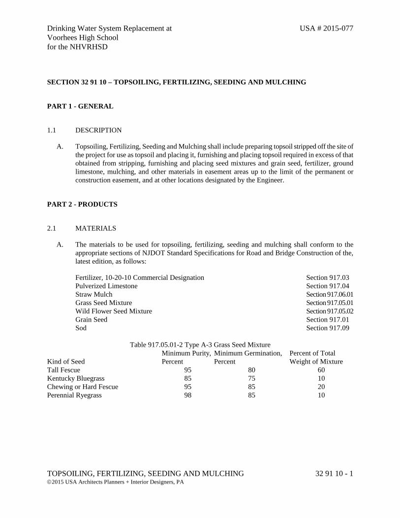
Drinking Water System Replacement at USA # 2015-077 Voorhees High School for the NHVRHSD
TOPSOILING, FERTILIZING, SEEDING AND MULCHING 32 91 10 - 1 2015 USA Architects Planners + Interior Designers, PA
SECTION 32 91 10 – TOPSOILING, FERTILIZING, SEEDING AND MULCHING
PART 1 - GENERAL
1.1 DESCRIPTION
A. Topsoiling, Fertilizing, Seeding and Mulching shall include preparing topsoil stripped off the site of the project for use as topsoil and placing it, furnishing and placing topsoil required in excess of that obtained from stripping, furnishing and placing seed mixtures and grain seed, fertilizer, ground limestone, mulching, and other materials in easement areas up to the limit of the permanent or construction easement, and at other locations designated by the Engineer.
PART 2 - PRODUCTS
2.1 MATERIALS
A. The materials to be used for topsoiling, fertilizing, seeding and mulching shall conform to the appropriate sections of NJDOT Standard Specifications for Road and Bridge Construction of the, latest edition, as follows:
Fertilizer, 10-20-10 Commercial Designation Section 917.03 Pulverized Limestone Section 917.04 Straw Mulch Section 917.06.01 Grass Seed Mixture Section 917.05.01 Wild Flower Seed Mixture Section 917.05.02 Grain Seed Section 917.01
Sod Section 917.09
Table 917.05.01-2 Type A-3 Grass Seed Mixture
Kind of Seed Minimum Purity, Percent
Minimum Germination, Percent
Percent of Total Weight of Mixture
Tall Fescue 95 80 60 Kentucky Bluegrass 85 75 10 Chewing or Hard Fescue 95 85 20 Perennial Ryegrass 98 85 10
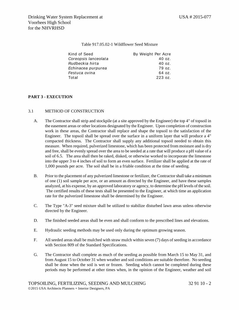
Drinking Water System Replacement at USA # 2015-077 Voorhees High School for the NHVRHSD
TOPSOILING, FERTILIZING, SEEDING AND MULCHING 32 91 10 - 2 2015 USA Architects Planners + Interior Designers, PA
Table 917.05.02-1 Wildflower Seed Mixture
Kind of Seed By Weight Per Acre Coreopsis lanceolata 40 oz. Rudbeckia hirta 40 oz. Echinacea purpurea 79 oz. Festuca ovina 64 oz. Total 223 oz.
PART 3 - EXECUTION
3.1 METHOD OF CONSTRUCTION
A. The Contractor shall strip and stockpile (at a site approved by the Engineer) the top 4" of topsoil in the easement areas or other locations designated by the Engineer. Upon completion of construction work in these areas, the Contractor shall replace and shape the topsoil to the satisfaction of the Engineer. The topsoil shall be spread over the surface in a uniform layer that will produce a 4" compacted thickness. The Contractor shall supply any additional topsoil needed to obtain this measure. When required, pulverized limestone, which has been protected from moisture and is dry and free, shall be evenly spread over the area to be seeded at a rate that will produce a pH value of a soil of 6.5. The area shall then be raked, disked, or otherwise worked to incorporate the limestone into the upper 3 to 4 inches of soil to form an even surface. Fertilizer shall be applied at the rate of 1,000 pounds per acre. The soil shall be in a friable condition at the time of seeding.
B. Prior to the placement of any pulverized limestone or fertilizer, the Contractor shall take a minimum of one (1) soil sample per acre, or an amount as directed by the Engineer, and have these samples analyzed, at his expense, by an approved laboratory or agency, to determine the pH levels of the soil. The certified results of these tests shall be presented to the Engineer, at which time an application rate for the pulverized limestone shall be determined by the Engineer.
C. The Type "A-3" seed mixture shall be utilized to stabilize disturbed lawn areas unless otherwise directed by the Engineer.
D. The finished seeded areas shall be even and shall conform to the prescribed lines and elevations.
E. Hydraulic seeding methods may be used only during the optimum growing season.
F. All seeded areas shall be mulched with straw mulch within seven (7) days of seeding in accordance with Section 809 of the Standard Specifications.
G. The Contractor shall complete as much of the seeding as possible from March 15 to May 31, and from August 15 to October 31 when weather and soil conditions are suitable therefore. No seeding shall be done when the soil is wet or frozen. Seeding which cannot be completed during these periods may be performed at other times when, in the opinion of the Engineer, weather and soil
Drinking Water System Replacement at USA # 2015-077 Voorhees High School for the NHVRHSD
TOPSOILING, FERTILIZING, SEEDING AND MULCHING 32 91 10 - 3 2015 USA Architects Planners + Interior Designers, PA
conditions are suitable. A satisfactory stand of grass and legumes practically weed-free shall be established in all areas of topsoiling. All areas of topsoiling and seeding in which a satisfactory stand of grass and legumes is not produced shall be refertilized, reseeded and remulched by the Contractor, as directed by the Engineer, until a satisfactory stand of grass and legumes is established.
H. If, in the opinion of the Engineer, the quantity of topsoil obtained from stripping, or from storage piles when prescribed, or from both, is insufficient for the requirements of the project, the Contractor shall furnish the required additional topsoil of the quality specified herein from other sources.
PART 4 - PAYMENT
4.1 QUANTITY AND PAYMENT
A. No separate payment shall be made for this section. The cost shall be included within the various items bid in the Proposal.
END OF SECTION 32 91 10

Drinking Water System Replacement at USA # 2015-077 Voorhees High School for the NHVRHSD
POLYETHYLENE PRESSURE PIPE AND TUBING 33 05 33 - 1 2015 USA Architects Planners + Interior Designers, PA
SECTION 33 05 33 – POLYETHYLENE PRESSURE PIPE AND TUBING
PART 1 - GENERAL
1.1 DESCRIPTION
A. This section includes the construction of High Density Polyethylene (HDPE) pressure piping and appurtenances at the locations shown on the plans and shall include performing all operations on connection with the installation of all pipe, fittings, adapters, valves, valve boxes and chambers, connections to existing manhole, concrete encasement, bedding, trenching, backfilling, accessories, appurtenances, miscellaneous work, and the testing and disinfection of the entire new system.
1.2 REFERENCED SECTIONS
A. Conform with the following sections:
1. Section 31 23 33 Trenching and Backfilling;
2. Section 33 11 00 Water Utility Distribution Piping;
3. Section 33 11 20 Bedding.
PART 2 - PRODUCTS
2.1 PERFORMANCE REQUIREMENTS
A. All piping and fittings shall conform to the AWWA C901 and AWWA C906 latest editions.
2.2 MATERIALS
A. The quality of all materials, manufacturing procedures, and the finished pipe shall be subject to inspection and approval of the Engineer. Such inspection may be made at the place of manufacturer and/or at the work site after delivery, and the pipe shall be subject to rejection at any time on account of failure to meet any of the specification requirements, even though sample pipes may have been accepted as satisfactory at the place of manufacture.
Drinking Water System Replacement at USA # 2015-077 Voorhees High School for the NHVRHSD
POLYETHYLENE PRESSURE PIPE AND TUBING 33 05 33 - 2 2015 USA Architects Planners + Interior Designers, PA
2.3 PIPING
A. High Density Polyethylene (HDPE) shall be DR11 470IPS. The HDPE pipe and fittings shall be made from virgin resin exhibiting a cell classification of PE 345464C as defined in ASTM D3350 with an established Hydrostatic C – Design – Basis of 160 PSI for water at 73°F. The resin shall be listed by the Plastic Pipe Institute (PPI) in its Pipe Grade Registry Technical Report (TR) 4, “Listing of plastic pipe compounds”.
B. Pipe shall be joined by a means of zero leak-rate heat-fusion joint system proven for HDPE pipe. Electro fusion and/or mechanical joint systems shall be utilized only where specifically called for on the plans or approved by the Engineer.
C. The wall thickness shall follow the standard dimension ratio (SDR) system prescribed in the ASTM-F714.
D. Piping and fittings within wet well, all manholes, valve chambers shall be schedule 80 PVC and shall conform to the requirements of ASTM D1785 latest edition schedule 80 PVC fittings shall conform to ASTM D2466. Joints are to be solvent welded and/or mechanical type proven for PVC pipe and fittings solvent cement shall conform to ASTM D2565. Transition from HDPE pipe to Schedule 80 PVC pipe shall be accomplished outside of structures.
E. The pipe shall be laid in a straight line on a firm foundation of 6” class “B” embedment material. It shall be laid at a uniform depth approximately 4’ below grade. See Water System Detail “HDPE Small Diameter HDPE Trench Detail”.
2.4 VALVES
A. Valves shall be as specified in Section 33 11 00 Water Utility Distribution Piping.
2.5 CONCRETE PIPE ENCASEMENT
A. Concrete encasement work shall include the construction of non-reinforced structures used for encasement or plugging purposes, as indicated in the contract documents, and as directed by the Engineer, and for which payment is not otherwise provided.
B. Concrete shall have a minimum twenty eight (28) day compressive strength of 2,500 lbs. per square inch. All materials shall conform to the applicable provisions of the latest edition of the American Concrete Institute Standards (ACI Standard 318, Building Code Requirements for Reinforced Concrete).
Drinking Water System Replacement at USA # 2015-077 Voorhees High School for the NHVRHSD
POLYETHYLENE PRESSURE PIPE AND TUBING 33 05 33 - 3 2015 USA Architects Planners + Interior Designers, PA
2.6 BROKEN STONE
A. Unless otherwise approved by the Engineer, broken stone shall be installed as bedding for all valves. Broken stone shall be nominal 3/4" size conforming to the requirements of Section 33 11 20 Bedding. Bedding for pipe shall not be installed unless directed by the Engineer.
PART 3 - EXECUTION
3.1 CUTTING AND REMOVING PAVEMENT
A. The line between the trench and the existing pavement to remain shall be cut with a saw, pneumatically operated spade, or approved equal, so as to leave a smooth, straight, and vertical edge. The existing pavement may be bituminous, brick, block non reinforced concrete, reinforced concrete, etc. The excavated pavement shall be broken up and removed to a site approved by the Engineer.
B. Where excavations are to be made on concrete roads, the existing concrete shall first be saw cut and removed. All protruding reinforcing roads shall be cut off and removed. Any loose or broken longitudinal portions of adjacent existing lanes shall be removed and replaced as directed by the Engineer.
3.2 UNDERGROUND UTILITIES
A. It is the responsibility of the Contractor to verify the location of all existing utilities whether shown on the plans or not.
B. Whenever a utility line is crossed or in any way exposed during this construction, the Contractor shall brace the utility line to the satisfaction of the Owner of the utility. The utility line shall be supported as soon as the existing support is removed and until the trench is backfilled.
3.3 EXCAVATION
A. The trench shall be excavated along the lines designated by the Engineer and to a depth sufficient to provide cover over the mains of not less than three (4') feet, except where greater or lesser depths of cover are shown on the detailed plans or are necessary due to the existence of utilities or to connect to existing lines. The trench shall be not less than one foot and not more than two feet wider at the bottom than the outside diameter of the pipe. The bottom of the trench under each joint shall be so hollowed out to allow the body of the pipe to have bearing along the entire length of trench if and where the trench is excavated at any place below the proper grade, excepting at joints, it shall be refilled to grade with sand or loam and thoroughly compacted.
B. The Engineer shall have the right to limit (to 100' maximum) the amount of trench which shall be opened in advance of the completed pipe laying work and to limit (to 200' maximum) the amount of trench left unfilled, backfilled and unpaved.
Drinking Water System Replacement at USA # 2015-077 Voorhees High School for the NHVRHSD
POLYETHYLENE PRESSURE PIPE AND TUBING 33 05 33 - 4 2015 USA Architects Planners + Interior Designers, PA
C. The material excavated shall be laid compactly on the side of the trench and kept trimmed up so that it will be of as little inconvenience as possible to the traveling public and to adjoining tenants. Where the streets are paved, the paving material shall be kept separate from the other materials excavated. All streets shall be kept open for travel unless otherwise approved by the Engineer. All clean excavated material shall become the property of the Borough and shall be deposited by the Contractor at a location approved by the Engineer.
D. All clean excavated material shall become the property of the Owner and shall be deposited by the Contractor at a location approved by the Engineer.
E. All debris and unsuitable material shall be removed and deposited at a location provided by the Contractor and approved by the Engineer. All costs for removing and depositing excess material shall be included in the price of the pipe. The Engineer alone shall determine if excess material is clean or not.
F. If in the opinion of the Engineer, the material at or below the grade to which excavation would normally be carried is unsuitable for foundation, or if the material from any other part of the trench is unsuitable for backfill, it shall be replaced at no additional cost to the Owner with suitable surplus material excavated from other parts of the Contract as specified below.
G. If suitable surplus material is not available from other parts of the Contract, then the Contractor shall furnish suitable material if and where directed by the Engineer.
3.4 SHEETING
A. The Contractor shall furnish, install in place, and maintain such sheeting and bracing, etc., as may be required to support the sides of the excavation and to prevent any movement of earth which could in any way diminish the width of the excavation below that necessary for proper construction, or otherwise injure or delay the work or endanger adjacent structures. If the Engineer is of the opinion that at any point, sufficient or proper supports have not been provided, he may order additional supports put in at the expense of the Contractor.
3.5 DEWATERING OF TRENCH
A. Conform with Section 31 23 33 Trenching and Backfilling.
B. All pipes shall be laid on a solid, dry foundation. The Contractor shall furnish all equipment, material and labor necessary to keep all trenches free from water that is above or below ground. Any pipe laid in water or wet trenches must be removed and reinstalled at the Contractor's expense.
C. The Contractor shall provide, maintain and operate such drains, percolation stone, trenches, sumps, pumps, hoses, piping, well pointing systems, and other approved methods and equipment as may be necessary to keep the excavations free from water during all stages of the construction operations and course of work. The Contractor shall provide such dikes, ditches, sumps and pumping that may also be required to prevent the flow of surface waters into excavated areas and into any and all areas where
Drinking Water System Replacement at USA # 2015-077 Voorhees High School for the NHVRHSD
POLYETHYLENE PRESSURE PIPE AND TUBING 33 05 33 - 5 2015 USA Architects Planners + Interior Designers, PA
construction or installations are in progress. All water pumped from the excavation shall be discharged in such manner as shall not cause injury to work completed, damage to property, health hazards or impediment to traffic. All costs for dewatering shall be included in the prices bid in the Proposal for the various items.
D. Water shall be completely removed from all excavations promptly and continuously throughout the progress of the work, and the Contractor shall keep excavations absolutely dry at all times until the water mains have been properly joined and bedded and work completed. Precautions shall be taken to protect uncompleted work from flooding during storms or from other causes.
3.6 INSTALLATION
A. Care shall be taken not to damage any materials in handling or installation of pipe, fittings, etc., and no smaller pieces or other materials of any kind shall be placed in the large pieces for transportation at any time. Any material found to have inherent defects upon delivery or to have been damaged in transportation will be rejected.
B. All pipe, fittings, adapters, valves and appurtenances shall be cleaned of foreign matter before being lowered into the trench and shall be kept clean during the laying operations by plugging or other approved means. Cutting of pipe shall be done in a neat and workmanlike manner with an approved type of mechanical cutter without damage to the pipe or lining so as to leave a smooth end at right angle to the axis of the pipe.
C. All joints of piping, couplings, fittings, valves, specials, etc., shall be made up in accordance with the manufacturer's printed recommendations.
D. Valves and valve boxes shall be set plumb with a 6" minimum base of broken stone or gravel. Valve boxes shall be centered on the gate valves and the box cover shall finish flush with the surface of the pavement or ground.
E. Methods of construction for concrete encasement work shall conform to all applicable requirements of the American Concrete Institute Standards, ACI Standard 318.
3.7 BACKFILLING
A. Conform with Section 31 23 33 Trenching and Backfilling.
B. Unless otherwise approved by the Engineer, the Contractor shall backfill all trenches at the end of each working day with suitable material from the trench excavation or temporary stockpile. Backfill shall be brought to elevations which allow construction of temporary paving specified elsewhere in these specifications. Backfill material shall be deposited and mechanically compacted to a minimum 90 percent Modified Proctor Density in layers not exceeding 6" in depth (loose measure) to a point 12" above the top of the pipe. From this point, all backfill shall be mechanically compacted in maximum 12" lifts, unless otherwise approved by the Engineer, to obtain a minimum 90 percent Modified Proctor Density to a point 3' below the road surface. From this point, a minimum 95 percent Modified Proctor
Drinking Water System Replacement at USA # 2015-077 Voorhees High School for the NHVRHSD
POLYETHYLENE PRESSURE PIPE AND TUBING 33 05 33 - 6 2015 USA Architects Planners + Interior Designers, PA
Density is required. Smaller lifts shall be required if this density is not obtained. The backfill material shall be wet or dried as required to obtain the required density.
C. The only methods of compaction of the backfill material permitted shall be mechanical compaction in lifts as specified. Consolidation will not be acceptable as a method to achieve the soil densities specified.
D. The Engineer, at his discretion, may perform, or have performed soil density checks at randomly chosen lifts. Density testing will be performed at the completion of the compaction effort. Compaction requirements will be strictly enforced.
E. When the trench is not in or across a dedicated street, right of way, or any other place where pavement is to be constructed, backfill shall be compacted to obtain a minimum 90 percent Modified Proctor Density.
F. The densities referred to above shall be based upon the latest Standard Test Methods for Moisture-Density Relations of Soil and Soil Aggregate Mixtures Using 10 lb. Rammer and 18" Drop, ASTM Designation D 1557. Density control in the field shall be based on the latest Test for Density of Soil in Place by the Sand/Cone Method, ASTM Designation D 1556. The Owner may retain and, except as otherwise specified, pay for the services of an independent testing laboratory to do such sampling and to make such tests as the Owner or Engineer may deem necessary to verify that work conforms to the requirements of the specifications.
3.8 TEMPORARY PAVEMENT REPAIRS
A. During the interval between the completion of backfill and the time of placement of permanent paving, all pavement and drives shall be maintained in a safe and satisfactory condition. The Contractor shall install all temporary pavement repairs in accordance with these specifications.
B. Temporary pavement repair shall be constructed within 24 hours of completion of backfill, unless otherwise approved by the Engineer.
C. Temporary pavement repair shall consist of 4" minimum (compacted measure) of cold patch on all Borough roads and 6" (compacted measure) of cold patch on County and State Roads. Prior to placing of cold patch, the trench shall be thoroughly cleaned of all loose and foreign material. It shall not be applied when surface is wet or dusty. Application shall be made only when the condition of the surface is acceptable to the Engineer.
D. The Contractor shall continuously maintain temporary paving for the entire period it remains in place; shall inspect trenches at such intervals as may be necessary, including but not limited to immediately following rainstorms, winter thaws, and similar occurrences which may cause settlement, erosion, or other problems; and shall promptly make necessary repairs to maintain trenches in a satisfactory condition. In the event the Contractor fails to make such repairs, the Owner may make such repairs as are deemed necessary and the Contractor shall pay for the cost of this work.
Drinking Water System Replacement at USA # 2015-077 Voorhees High School for the NHVRHSD
POLYETHYLENE PRESSURE PIPE AND TUBING 33 05 33 - 7 2015 USA Architects Planners + Interior Designers, PA
E. The Contractor is required to repair all areas that are damaged by his actions during construction. If the damaged areas are outside the maximum trench width shown in the detail, additional costs of restoring the damaged areas shall be borne by the Contractor.
F. The Engineer, giving one week's notice, may direct the Contractor to remove the cold patch surface and replace it with the permanent base course (bituminous stabilized base).
G. If, at the time of the placement of temporary pavement, it is demonstrated that the Contractor's compaction method has achieved the specified soil densities within the 24 hour time limit for the placement of temporary pavement, the Engineer will approve the placement of the permanent base course in lieu of cold patch. If the specified soil densities are not achieved within this time limit, the Contractor will be required to place cold patch as specified. The placement of cold patch should not be construed as relieving the Contractor from any of the requirements of the backfilling specifications.
3.9 TESTING
A. All pipes, fittings, valves, equipment, etc. shall be pressure tested prior to construction of permanent pavement repair. All materials and equipment required for testing shall be supplied by the Contractor.
B. All pipe, fittings, valves, equipment, etc. testing shall be performed by Developer/ Builder at his expense in presence of Owner and/or his representative and the local Municipal and/or Sewerage Authority representative as follows:
1. Upon completion of the HDPE piping, it shall be tested as one complete unit (including any pipe, fittings, equipment, valves, etc.) from beginning to end, filled with water.
2. The pressure test shall be performed by increasing the hydrostatic pressure to a specified value and maintaining that pressure for a period of one (1) hour, with no pressure drop allowable.
3. Prior to performing the test, all air pockets and bubbles must be eliminated from the force main.
4. The point of testing shall be at the low point of each system at a hydrostatic test pressure of 125 psi, with no pressure drop allowable.
5. Duration of each pressure test shall be one (1) hour, with no pressure drop allowable.
6. The Contractor shall provide a certification of all pipe tests.
C. If any test of pipe, fittings, valves, equipment, etc. fails per the criteria detailed above, the Contractor shall, at his own expense, locate and repair the defect(s) until the tests are within the specified criteria.
Drinking Water System Replacement at USA # 2015-077 Voorhees High School for the NHVRHSD
POLYETHYLENE PRESSURE PIPE AND TUBING 33 05 33 - 8 2015 USA Architects Planners + Interior Designers, PA
PART 4 - PAYMENT
4.1 QUANTITY AND PAYMENT
A. No separate payment shall be made for this section. The cost shall be included within the various items bid in the Proposal.
END OF SECTION 33 05 33
Drinking Water System Replacement at USA # 2015-077 Voorhees High School for the NHVRHSD
WATER UTILITY DISTRIBUTION PIPING 33 11 00 - 1 2015 USA Architects Planners + Interior Designers, PA
SECTION 33 11 00 – WATER UTILITY DISTRIBUTION PIPING
PART 1 - GENERAL
1.1 DESCRIPTION
A. This section includes the construction of water mains and appurtenances at the locations shown on the plans and shall include performing all operations in connection with the installation of all pipe, fittings, adapters, gate valves, valve boxes, hydrants, connections to existing and new piping, mechanical joint restraints, plastic and concrete encasement, bedding, trenching, backfilling, accessories, appurtenances, miscellaneous work, and the testing and disinfection of the entire new system.
1.2 SUBMITTALS
A. Submittals shall be made to the Engineer in accordance with the General Conditions of the Contract. Submittals are often made under the general term of "Shop Drawings" but include all items listed in the General Conditions.
B. Some submittal requirements listed in the General Conditions or within specifications are not ordinarily termed as Shop Drawings but still must be submitted as above.
C. Shop Drawings and Product Data:
1. Existing Piping layouts in full detail including sizes and locations.
2. Location of pipe hangers and supports.
3. Location and type of backup block or device to prevent joint separation.
4. Large scale details of wall penetrations and fabricated fittings.
5. Schedules of all pipe fittings, special castings, couplings, expansion joints and other appurtenances.
6. Catalog cuts of pipe, valve joints, couplings, harnesses, expansion joints, gaskets, fasteners and other accessories.
7. Brochures and technical data on coatings and linings and proposed method for application and repair.
Drinking Water System Replacement at USA # 2015-077 Voorhees High School for the NHVRHSD
WATER UTILITY DISTRIBUTION PIPING 33 11 00 - 2 2015 USA Architects Planners + Interior Designers, PA
D. Test Reports
1. Five (5) copies of certified shop tests showing compliance with appropriate standard.
2. Five (5) copies of all field test reports, signed by Contractor.
E. In addition, the Contractor shall submit to the Engineer, copies of purchase orders, delivery tickets, and/or invoice for all materials delivered and installed.
PART 2 - PRODUCTS
2.1 MATERIALS
A. The quality of all materials, manufacturing procedures, and the finished pipe shall be subject to inspection and approval of the Engineer. Such inspection may be made at the place of manufacture and/or at the work site after delivery, and the pipe shall be subject to rejection at any time on account of failure to meet any of the specification requirements even though sample pipes may have been accepted as satisfactory at the place of manufacture.
2.2 DUCTILE IRON PIPE (DIP)
A. All ductile iron pipe shall be centrifugally cast pipe conforming to the American National Standard for Ductile Iron Pipe, Centrifugally Cast in Metal Molds or Sand-Lined Molds for Water or Other Liquids, ANSI/AWWA Designation A21.51/C 151, latest revision. Pipe sizes shall be as shown on the contract drawings with a thickness class of 50, unless otherwise indicated on the plans. All pipe fittings shall have joints with body thickness and radii of curvature conforming to ANSI/AWWA Designation A21.10/C 110, latest edition.
B. Joints shall employ a single, elongated gasket of such size and shape as to provide an adequate compressive force against the spigot and socket after assembly to effect a positive seal under all combinations of joint and gasket tolerances. Joints shall be U.S. Pipe and Foundry Company's "Tyton" joint, Griffin Pipe Products Company's "Super Bell-Tite" joint, or approved equal conforming to American National Standard for Rubber Gasket Joints for Cast Iron and Ductile Iron Pressure Pipe and Fittings, ANSI/AWWA Designation A21.11/C.111, latest edition. Gaskets shall be vulcanized natural or vulcanized synthetic rubber, resistant to common ingredients of sewage, industrial wastes, including oils and groundwater. Gaskets shall be free of porous areas, foreign material, and visible defects. Joint lubricants shall be suitable for lubricating the joint assembly. Parts shall be nontoxic, shall not support the growth of bacteria and shall have no deteriorating effects on the gasket material.
C. All ductile iron pipes shall be externally coated with a uniform thickness (approximately 1 mm thick) of hot-applied coal tar coating. The finished coating shall be neither brittle when cold, nor sticky when exposed to the sun, and shall be strongly adherent to the pipe. The pipe interior shall have cement mortar lining and bituminous sealed coating in accordance with the latest ANSI/AWWA
Drinking Water System Replacement at USA # 2015-077 Voorhees High School for the NHVRHSD
WATER UTILITY DISTRIBUTION PIPING 33 11 00 - 3 2015 USA Architects Planners + Interior Designers, PA
Designation A21.4/C-104 for Cement-Mortar Lining for Cast Iron and Ductile Iron Pipe and Fittings for Water.
2.3 COMPRESION-SLEEVE COUPLING
A. Couplings shall be designed to couple plain end piping by compression of a ring gasket at each end of the adjoining pipe sections. The coupling shall consist of one middle ring flared or beveled at each end to provide a gasket seat; two follower rings; two resilient tapered rubber gaskets; and bolts and nuts to draw the follower rings toward each other to compress the gaskets. The middle and the follower rings shall be true circular sections free from irregularities, flat spots, and surface defects, and the design shall be such as to provide for confinement and compression of the gaskets. For cast gray and ductile iron piping the middle ring shall be of cast iron or steel and the follower rings shall be of malleable iron.
B. Cast iron shall conform to ASTM A48 and shall be not less than Class 25. Malleable iron shall conform to ASTM A47. Gaskets shall be designed for long life and resistance to set after installation and shall meet the applicable requirements specified for gaskets for mechanical joint in ANSI A21.11 (AWWA C111). Bolts shall be track head type; bolts and nuts shall conform to the tensile requirements of ASTM A307, Grade A; or bolts shall be round head square neck type conforming to ANSI B18.5 with hex nuts conforming to ANSI/B18.2.2. Bolts shall be 5/8 inch in diameter; minimum number of bolts for each coupling shall be as recommended by the manufacturer.
C. Bolt holes in follower rings shall be of a shape to hold fast the necks of the bolts used. Sleeve type mechanical coupling shall not be used as an optional method of joining except where pipeline is adequately anchored to resist tension pull across the joint.
2.4 CAST/DUCTILE IRON FITTINGS
A. All cast/ductile iron fittings shall be Class 250 suitable for use with the pipe specified above conforming to the American National Standard for Gray Iron and Ductile Iron Fittings, 2" through 48" for Water and Other Liquids, ANSI Designation A21.10. Fittings shall be externally coated with a uniform thickness of hot applied coal tar coating and the inside shall be cement lined and only mechanical joint fittings shall be used. End plugs shall be setscrew type, as manufactured by the United States Pipe and Foundry Co., or approved equal.
2.5 GATE VALVES
A. Gate valves shall be AWWA non rising stem type with valve box, as manufactured by Mueller Company or approved equal, conforming to the latest AWWA Standard for Gate Valves - 3" through 48" - for Water and Other Liquids, AWWA Designation C 509. Sizes up to and including 12" shall be 200 psi working pressure; sizes 14" and larger shall be 150 psi working pressure. Valves shall have dual "O" ring seals, inside screw, resilient wedge seats in accordance with AWWA designation C-550 and shall be constructed so as to provide unobstructed full port clearance when fully open and immediate complete closure when closed. The ends of the valves shall correspond in type and
Drinking Water System Replacement at USA # 2015-077 Voorhees High School for the NHVRHSD
WATER UTILITY DISTRIBUTION PIPING 33 11 00 - 4 2015 USA Architects Planners + Interior Designers, PA
dimensions with those of the pipe. All valves shall be arranged to open in counter clockwise direction unless otherwise specifically indicated and operating nuts shall be 2" square.
B. Valves shall be tested to a pressure of not less than two times the working pressure. All buried valves shall be furnished with standard weight cast iron valve boxes. Boxes shall be of the Bingham Taylor Company Telescope Screw type or approved equal with round or oval base and deep cover to prevent tipping and shall be suitably marked with the word "WATER." Sections shall not be less than 5-1/4" in diameter. Lengths shall be suitable for locations intended. Two 2" square nut-operating wrenches of suitable lengths shall be provided.
2.6 TAPPING/INSERTING SLEEVES AND VALVES
A. Tapping/inserting sleeves shall be extra heavy pattern of the sizes suitable for use on the pipe on which the respective sleeve is to be installed and for use with the tapping/ inserting valves. They shall be designed for a working pressure of 250 psi and of the same manufacturer as the tapping/inserting valves. Cast iron sleeves shall be as manufactured by Mueller Company or an approved equal.
B. Tapping/inserting valves shall be of the same manufacturer as the tapping sleeves and meet all requirements for "Gate Valves" previously specified.
2.7 BUTTERFLY VALVES
A. All butterfly valves shall be manufactured in accordance with the latest revision of AWWA C504 for Class 150B service and comply with the following details:
B. Valve Bodies - Valve bodies shall be constructed of cast iron ASTM A-126 Class B and conform to AWWA C504 in terms of laying lengths and minimum body shell thickness. End connections shall be as specified on the plans.
C. Valve Discs - Valve discs shall also be made from cast iron ASTM A-126 Class B or ASTM A-48 Class 40 in sizes 24" and smaller. Sizes 30" and larger shall be built from ductile iron in conformance to ASTM A-536. Disc shall be furnished with 316 stainless steel seating edge to mate with the rubber seat on the body.
D. Valve Seat - Valve seat shall be Buna-N rubber located on the valve body. In sizes 20" and smaller, valves shall have bonded seats that meet test procedures outlined in ASTM D-429 Method B. Sizes 24" and larger shall be retained in the valve body by mechanical means without use of metal retainers or other devices located in the flow stream.
E. Valve Shaft - Valve shafts shall be 18-8 type 304 stainless steel conforming to ASTM A-276. Shaft seals shall be standard self-adjusting split V packing. Shaft seals shall be of a design allowing replacement without removing the valve shaft.
F. Valve Bearings - Valve bearings shall be sleeve type that are corrosion resistant and self-lubricating.
Drinking Water System Replacement at USA # 2015-077 Voorhees High School for the NHVRHSD
WATER UTILITY DISTRIBUTION PIPING 33 11 00 - 5 2015 USA Architects Planners + Interior Designers, PA
G. Actuators - Valve actuators shall be fully grease packed and have stops in the open/close position. The actuator shall have a mechanical stop which will withstand an input torque of 450 ft. lbs. against the stop. The traveling nut shall engage alignment grooves in the housing. The actuators shall have a built in packing leak bypass to eliminate possible packing leakage into the actuator housing.
H. Surfaces - All internal and/or external surfaces shall be covered with a polyamide cured epoxy coating applied over a sand blasted "new white metal surface" per SSPC-SP10 to a minimum of 6 mils in compliance with AWWA C550.
2.8 NON-FREEZE YARD HYDRANTS
A. All new yard hydrants shall be A.S.S.E. 1019-B certified exposed type, self-draining, non-freeze wall hydrant with A.S.S.E. 1011 approved anti-siphon and vandal resistant integral vacuum breaker with 3/4" (19) male hose connection. Hydrant shall have the assembly complete with neoprene plunger to control both the flow and drain functions, hardened bronze operating stem, drain port under the hexagon nut, heavy duty brass casing, heavy duty chrome plated bronze head casting,360o swivel inlet connection (1/2” sweat, 3/4" I.P.S.) and polished chrome plated face plate. Operating key to be furnished with each hydrant.
2.9 CONCRETE PIPE ENCASEMENT
A. Concrete encasement work shall include the construction of non-reinforced structures used for encasement or plugging purposes, as indicated in the contract documents, and as directed by the Engineer, and for which payment is not otherwise provided.
B. Concrete shall have a minimum twenty-eight (28) day compressive strength of 2,500 lbs. per square inch. All materials shall conform to the applicable provisions of the latest edition of the American Concrete Institute Standards (ACI Standard 318, Building Code Requirements for Reinforced Concrete).
2.10 MECHANICAL JOINTS
A. Restraint devices for mechanical joint fittings and appurtenances conforming to either ANSI/AWWA C111/A21.11 or ANSI/AWWA C153/A21.53.
B. Restraint devices for nominal pipe sizes 3 inch through 54 inch shall consist of multiple gripping wedges incorporated into a follower gland meeting the applicable requirements of ANSI/AWWA C110/A21.10.
C. The devices shall have a working pressure rating of 350 psi for 3-16 inch, 250 psi for 18-48 inch and 200 psi for the 54 inch size. Ratings are for water pressure and must include a minimum safety factor of 2 to 1 in all sizes.
Drinking Water System Replacement at USA # 2015-077 Voorhees High School for the NHVRHSD
WATER UTILITY DISTRIBUTION PIPING 33 11 00 - 6 2015 USA Architects Planners + Interior Designers, PA
D. Gland body, wedges and wedge actuating components shall be cast from grade 65-45-12 ductile iron material in accordance with ASTM A536.
E. Ductile iron gripping wedges shall be heat treated within a range of 370 to 470 BHN.
F. Three (3) test bars shall be incrementally poured per production shift as per Underwriter’s Laboratory (U.L.) specifications and ASTM A536. Testing for tensile, yield and elongation shall be done in accordance with ASTM E8.
G. Chemical and nodularity tests shall be performed as recommended by the Ductile Iron Society, on a per ladle basis.
H. Mechanical joint restraint shall require conventional tools and installation procedures per AWWA C600, while retaining full mechanical joint deflection during assembly as well as allowing joint deflection after assembly.
I. Proper actuation of the gripping wedges shall be ensured with torque limiting twist off nuts.
2.11 BROKEN STONE
A. Unless otherwise approved by the Engineer, broken stone shall be installed as bedding for all valves and hydrants. Broken stone shall be nominal 3/4" size conforming to the requirements of Section 33 11 20 Bedding. Bedding for pipe shall not be installed unless directed by the Engineer. The pipe bedding, if approved by the Engineer, shall be in conformance with these specifications.
2.12 FLEXIBLE RUBBER EXPANSION JOINT
A. Rubber expansion joints shall be of radial cord design construction of food grade neoprene of the size suitable for use on the pipe being utilized. They shall be designed for a working pressure of 200 PSI and shall be supplied with split, zinc-coated retaining rings. Material for retaining rings shall be ASTM-A536 steel.
PART 3 - EXECUTION
3.1 CUTTING AND REMOVING PAVEMENT
A. The line between the trench and the existing pavement to remain shall be cut with a saw, pneumatically operated spade, or approved equal, so as to leave a smooth, straight, and vertical edge. The existing pavement may be bituminous, brick, block, non-reinforced concrete, reinforced concrete, etc. The excavated pavement shall be broken up and removed to a site approved by the Engineer.
Drinking Water System Replacement at USA # 2015-077 Voorhees High School for the NHVRHSD
WATER UTILITY DISTRIBUTION PIPING 33 11 00 - 7 2015 USA Architects Planners + Interior Designers, PA
B. Where excavations are to be made on concrete roads, the existing concrete shall first be saw cut and removed. All protruding reinforcing rods shall be cut off and removed. Any loose or broken longitudinal portions of adjacent existing lanes shall be removed and replaced as directed by the Engineer.
3.2 UNDERGROUND UTILITIES
A. It is the responsibility of the Contractor to verify the location of all existing utilities whether shown on the plans or not.
B. Whenever a utility line is crossed or in any way exposed during this construction, the Contractor shall brace the utility line to the satisfaction of the Owner of the utility. The utility line shall be supported as soon as the existing support is removed and until the trench is backfilled.
3.3 EXCAVATION
A. All excavation and trenching shall be done in accordance with Section 31 23 33 Trenching and Backfill.
B. The trench shall be excavated along the lines designated by the Engineer and to a depth sufficient to provide a cover over the mains of not less than four feet (4') except where greater or lesser depths of cover are shown on the detailed plans or are necessary due to the existence of utilities or to connect to existing lines. The trench shall be not less than one foot and not more than two feet wider at the bottom than the outside diameter of the pipe. The bottom of the trench under each joint shall be so hollowed out to allow the body of the pipe to have bearing along the entire length of trench if and where the trench is excavated at any place below the proper grade, excepting at joints, it shall be refilled to grade with sand or loam and thoroughly compacted.
C. The Engineer shall have the right to limit (to 100' maximum) the amount of trench, which shall be opened in advance of the completed pipe laying work and to limit (to 200' maximum) the amount of trench left unfilled, backfilled and unpaved.
D. The material excavated shall be laid compactly on the side of the trench and kept trimmed up so that it will be of as little inconvenience as possible to the traveling public and to adjoining tenants. Where the streets are paved, the paving material shall be kept separate from the other materials excavated. All streets shall be kept open for travel unless otherwise approved by the Engineer.
E. All clean excavated material shall become the property of the Owner, if requested, and shall be deposited by the Contractor at a location approved by the Engineer.
F. All debris and unsuitable material and other material not desired by the Owner shall be removed and deposited at a location provided by the Contractor and approved by the Engineer. All costs for removing and depositing excess material shall be included in the price of the pipe. The Engineer alone shall determine if excess material is clean or not.
Drinking Water System Replacement at USA # 2015-077 Voorhees High School for the NHVRHSD
WATER UTILITY DISTRIBUTION PIPING 33 11 00 - 8 2015 USA Architects Planners + Interior Designers, PA
G. If, in the opinion of the Engineer, the material at or below the grade to which excavation would normally be carried is unsuitable for foundation, or if the material from any other part of the trench is unsuitable for backfill, it shall be replaced at no additional cost to the Owner with suitable surplus material excavated from other parts of the Contract as specified below.
H. If suitable surplus material is not available from other parts of the Contract, then the Contractor shall furnish suitable material if and where directed by the Engineer. The cost of the suitable material will be included and paid for under the item entitled, "Borrow Excavation".
3.4 SHEETING
A. The Contractor shall furnish, install in place and maintain such sheeting and bracing, etc., as may be required to support the sides of the excavation and to prevent any movement of earth which could in any way diminish the width of the excavation below that necessary for proper construction, or otherwise injure or delay the work or endanger adjacent structures. If the Engineer is of the opinion that at any point, sufficient or proper supports have not been provided, he may order additional supports put in at the expense of the Contractor.
B. No separate payment will be made for sheeting if required. The cost of sheeting shall be included in the various bid items as set forth in the Proposal.
3.5 DEWATERING OF TRENCH
A. All pipes shall be laid on a solid, dry foundation. The Contractor shall furnish all equipment, materials and labor necessary to keep all trenches free from water that is above or below ground. Any pipe laid in water or wet trenches will be removed and reinstalled at the Contractor's expense.
B. The Contractor shall provide, maintain, and operate such drains, percolation stone, trenches, sumps, pumps, hoses, piping, well- pointing systems, and other approved methods and equipment as may be necessary to keep the excavations free from water during all stages of the construction operations and course of work. The Contractor shall provide such dikes, ditches, sumps and pumping that may also be required to prevent the flow of surface waters into excavated areas and into any and all areas where construction or installations are in progress. All water pumped from the excavation shall be discharged in such a manner as shall not cause injury to work completed, damage to property, health hazards or impediment to traffic. All costs for dewatering shall be included in the prices bid in the Proposal for the various items.
C. Water shall be completely removed from all excavations promptly and continuously throughout the progress of the work, and the Contractor shall keep excavations absolutely dry at all times until the water mains have been properly joined and bedded and work completed. Precautions shall be taken to protect uncompleted work from flooding during storms or from other causes.
D. No separate payment shall be made for the dewatering of the trench. Dewatering shall be included in the various items as set forth in the Proposal.
Drinking Water System Replacement at USA # 2015-077 Voorhees High School for the NHVRHSD
WATER UTILITY DISTRIBUTION PIPING 33 11 00 - 9 2015 USA Architects Planners + Interior Designers, PA
3.6 INSTALLATION
A. Care shall be taken not to injure the coating or lining in handling pipe, fittings, etc. and no smaller pieces or other materials of any kind shall be placed in the large pieces for transportation at any time. Any material found to have inherent defects upon delivery or to have been injured in transportation will be rejected.
B. All pipe, fittings, adapters, valves, and appurtenances shall be cleaned of foreign matter before being lowered into the trench and shall be kept clean during the laying operations by plugging or other approved means. Cutting of pipe shall be done in a neat and workmanlike manner with an approved type of mechanical cutter without damage to the pipe or lining so as to leave a smooth end at right angle to the axis of the pipe.
C. All joints of piping, couplings, fittings, valves, specials, and fire hydrants, whether push on type or mechanical type, shall be made up in accordance with the manufacturer's printed recommendations.
D. The installation of tapping sleeves and valves for making wet taps under full main pressure shall be done only by workmen thoroughly experienced in this type of work. The existing main shall be thoroughly cleaned of all rust, dirt, scale or other materials down to the clean metal just prior to the installation of the tapping sleeve. Tapping connections shall be installed exactly horizontal and at right angles to the center line of the pipe to be tapped.
E. Gate valves and valve boxes shall be set plumb with a 6" minimum base of broken stone or gravel. Valve boxes shall be centered on the gate valves and the box cover shall finish flush with the surface of the pavement or ground.
F. Hydrants shall be set plumb and to the established grade with hose nozzles at least 18 inches above the ground or as directed. A concrete thrust block shall be provided at each hydrant and one cubic foot of broken stone or gravel.
G. Methods of Construction for concrete encasement work shall conform to all applicable requirements of the American Concrete Institute Standards, ACI Standard 318.
H. At all areas where ductile iron pipe is exposed to corrosive soil condition, runs parallel to cathodically protected gas lines on the same side of the road or crosses gas lines, the water main shall be protected by encasing the pipe with plastic in accordance with AWWA/ANSI Designation C105/A 21.5, latest edition. Polyethylene film shall be applied loosely but continuously to the pipe with joints in plastic made by polyethylene adhesive tape. Care shall be taken in the installation and backfilling operation to prevent tearing the plastic and exposing the bare metal pipe.
3.7 BACKFILLING
A. Unless otherwise approved by the Engineer, the Contractor shall backfill all trenches at the end of each working day with material specified in Section 31 23 33 Trenching and Backfill. Backfill shall be brought to elevations which allow construction of temporary paving specified elsewhere in these specifications. If, in the opinion of the Engineer, the above material is unsuitable, select off site
Drinking Water System Replacement at USA # 2015-077 Voorhees High School for the NHVRHSD
WATER UTILITY DISTRIBUTION PIPING 33 11 00 - 10 2015 USA Architects Planners + Interior Designers, PA
material shall be provided as described in Section 31 23 24 Borrow Excavation. Backfill material shall be deposited and mechanically compacted to a minimum 90 percent) Modified Proctor Density in layers not exceeding 6" in depth (loose measure) to a point 12" above the top of the pipe. From this point, all backfill shall be mechanically compacted in maximum 12" lifts, unless otherwise approved by the Engineer, to obtain a minimum 90 percent Modified Proctor Density to a point 3 feet below the road surface. From this point, a minimum 95 percent Modified Proctor Density is required. Smaller lifts shall be required if this density is not obtained. The backfill material shall be wet or dried as required to obtain the required density.
B. The only methods of compacting the backfill material permitted shall be mechanical compaction in lifts as specified. Consolidation will not be acceptable as a method to achieve the soil densities specified.
C. The Engineer, at his discretion, may perform, or have performed soil density checks at randomly chosen lifts. Density testing will be performed at the completion of the compaction effort. Compaction requirements will be strictly enforced.
D. When the trench is not in or across a dedicated street, right-of-way, or any other place where pavement is to be constructed, backfill shall be compacted to obtain a minimum 90 percent Modified Proctor Density.
E. The densities referred to above shall be based upon the latest Standard Test Methods for Moisture-Density Relations of Soil and Soil Aggregate Mixtures Using 10 lb. Rammer and 18" Drop, ASTM Designation D 1557. Density control in the field shall be based on the latest, ASTM Designation D 1556. The Owner may retain and, except as otherwise specified, pay for the services of an independent testing laboratory to do such sampling and to make such tests as the Owner or Engineer may deem necessary to verify that work conforms to the requirements of the specifications.
3.8 TEMPORARY PAVEMENT REPAIRS
A. During the interval between the completion of backfill and the time of placement of permanent paving, all pavement and drives shall be maintained in a safe and satisfactory condition. The Contractor shall install all temporary pavement repair where directed according to these specifications.
B. Temporary pavement repair shall be constructed prior to the placement of bituminous stabilized base course if directed by the Engineer.
C. Temporary pavement repair shall consist of 4" minimum (compacted measure) of cold patch on all Municipal roads and 6" (compacted measure) of cold patch on County and State roads. Prior to placing of cold patch, the trench shall be thoroughly cleaned of all loose and foreign material. It shall not be applied when surface is wet or dusty. Application shall be made only when the condition of the surface is acceptable to the Engineer.
D. The Contractor shall continuously maintain temporary paving for the entire period it remains in place; shall inspect trenches at such intervals as may be necessary, including but not limited to,
Drinking Water System Replacement at USA # 2015-077 Voorhees High School for the NHVRHSD
WATER UTILITY DISTRIBUTION PIPING 33 11 00 - 11 2015 USA Architects Planners + Interior Designers, PA
immediately following rainstorms, winter thaws, and similar occurrences which may cause settlement, erosion, or other problems; and shall promptly make necessary repairs to maintain trenches in a satisfactory condition. In the event the Contractor fails to make such repairs, the Owner may make such repairs as are deemed necessary and the Contractor shall pay for the cost of this work. The Contractor is required to repair all areas that are damaged by his actions during construction. If the damaged areas are outside the maximum trench width shown in the detail, additional costs of restoring the damaged areas shall be borne by the Contractor.
E. The Engineer, giving one week's notice, may direct the Contractor to remove the cold patch surface and replace it with the permanent base course (bituminous stabilized base).
F. If, at the time of the placement of temporary pavement, it is demonstrated that the Contractor's compaction method has achieved the specified soil densities within the 24 hour time limit for the placement of temporary pavement, the Engineer will approve the placement of the permanent base course in lieu of cold patch. If the specified soil densities are not achieved within this time limit, the Contractor will be required to place cold patch as specified. The placement of cold patch should not be construed as relieving the Contractor from any of the requirements of the backfilling specifications.
3.9 TESTING
A. All pipelines shall be pressure and leakage tested prior to construction of permanent pavement repair, a minimum of seven days after the last MegaLug has been cast if constructed with normal Portland cement. All materials and equipment required for testing shall be supplied by the Contractor.
B. Hydrostatic testing of ductile iron pipe shall conform to AWWA Standard C 600, Section 13 and AWWA Standard C 603, Section 19, respectively. The pressure test shall be performed by increasing the hydrostatic pressure to a specified value and maintaining that pressure for a period of one hour. Any pipe, fittings, or valves found defective shall be replaced. Prior to performing the test, all air pockets and bubbles must be eliminated. Hydrostatic test pressure for ductile iron pipe shall be 1.5 times the working pressure of the system at the point of testing or 150 psi, whichever is greater.
C. The leakage test shall be performed concurrently with the pressure test and shall be accomplished by increasing the hydrostatic pressure to a specified value and maintaining that pressure for a period of two hours. Leakage is the quantity of water that must be supplied into the newly laid pipe, or any valved section thereof, to maintain the specified leakage test pressure after the air in the pipeline has been expelled. The test pressure shall be 1.5 times the working pressure of the system at the point of testing or 150 psi whichever is greater. The leakage from each portion of the pipeline being tested shall not exceed 11.65 gallons per inch of internal diameter per mile of pipe per day. If any test of pipe laid discloses a greater leakage than specified, the Contractor shall, at his own expense, locate and repair the defective joints until the leakage is within the specified allowance.
Drinking Water System Replacement at USA # 2015-077 Voorhees High School for the NHVRHSD
WATER UTILITY DISTRIBUTION PIPING 33 11 00 - 12 2015 USA Architects Planners + Interior Designers, PA
3.10 DISINFECTION
A. All pipelines shall be disinfected and tested for bacteria in conformance with AWWA Standard C 601 for disinfecting water mains prior to being put into service. Hypochlorite and liquid chlorine for use in disinfection shall conform to AWWA Standards B 300 and B 301, respectively.
B. All pipelines shall be thoroughly flushed before introduction of chlorinating materials which shall be done in an approved manner. The amount of chlorine applied shall be such as to provide a dosage of not less than 50 parts per million. The chlorinated water shall be retained in the main for at least 24 hours during which time all hydrants and valves in the section treated shall be operated in order to be disinfected. At the end of the 24 hour period, the heavily chlorinated water shall be flushed from the main until the chlorine concentration in the water leaving the main is no higher than that generally prevailing in the system. The Contractor shall then have samples taken by an approved testing laboratory and bacteriological analyses made. Should the initial treatment prove ineffective, disinfection shall be repeated until satisfactory samples have been obtained. At minimum, Two (2) bacteria tests are required, the first prior to pressure/leakage test and the second after all tests/repairs are successfully completed.
3.11 APPROVALS
A. The Contractor shall furnish Shop Drawings, Catalogs, Specification Sheets and other Manufacturer's Literature for all equipment and materials he proposes to furnish. Such items should not be ordered until the Engineer's approval of the material submitted is obtained.
B. In addition, the Contractor shall submit to the Engineer, copies of purchase orders, delivery tickets, and/or invoice for all materials delivered and installed.
PART 4 - PAYMENT
4.1 QUANTITY AND PAYMENT
A. No separate payment shall be made for this section. The cost shall be included within the various items bid in the Proposal.
END OF SECTION 33 11 00

Drinking Water System Replacement at USA # 2015-077 Voorhees High School for the NHVRHSD
BEDDING 33 11 20 - 1 2015 USA Architects Planners + Interior Designers, PA
SECTION 33 11 20 – BEDDING
PART 1 - GENERAL
1.1 DESCRIPTION
A. This section includes furnishing and placing of embedment materials for water mains or other pipes or structures where shown on plans or directed by the Engineer.
PART 2 - PRODUCTS
2.1 MATERIALS
A. Bedding materials shall be NJDOT No. 67, 3/4" - No. 4 stone (See Table 901.03-1 in the Standard Specifications).
PART 3 - EXECUTION
3.1 METHOD OF CONSTRUCTION
A. Vitrified clay pipe (VCP), and ductile iron pipe (DIP) shall be constructed on dense graded aggregate (DGA) bedding which will be paid for under the Item “Borrow Excavation”. Polyvinyl chloride pipe (PVC) shall be constructed on 3/4” clean stone bedding as shown on the Standard Detail, "Typical Trench and Permanent Pavement Repair Detail” and “Typical Trench and Lawn Restoration Detail”.
B. Higher Class bedding shall be used only at the direction of the Engineer.
C. Bedding shall be placed to the limits and depths shown on the Standard Detail, or as designated by the Engineer. The embedment material shall be compacted in layers not exceeding 6" thickness (loose measure) with approved flat faced vibratory tampers. After compaction, the surface of the bedding shall be roughly shaped to receive the structure. Spaces shall be hollowed out to clear pipe bells so as to provide maximum bearing lengths.
Drinking Water System Replacement at USA # 2015-077 Voorhees High School for the NHVRHSD
BEDDING 33 11 20 - 2 2015 USA Architects Planners + Interior Designers, PA
PART 4 - PAYMENT
4.1 QUANTITY AND PAYMENT
A. No separate payment shall be made for this section. The cost shall be included within the various items bid in the Proposal.
END OF SECTION 33 11 20
Drinking Water System Replacement at USA # 2015-077 Voorhees High School for the NHVRHSD
PACKAGE PUMPING SYSTEMS FOR WATERUTILITY SERVICE 33 14 43 - 1 2015 USA Architects Planners + Interior Designers, PA
SECTION 33 14 43 – PACKAGE PUMPING SYSTEMS FOR WATER UTILITY SERVICE
PART 1 - GENERAL
1.1 SCOPE OF WORK
A. The replacement project includes: an above grade booster pump station with variable speed control vertical turbine pumps and a separate chemical feed room for water treatment for pH adjustment and disinfection. The proposed pump station will be placed on top of a below grade 20,000 gallon pre-cast concrete tank. A new electrical service will be provided to the proposed pump station with a dedicated emergency generator. The proposed system will be constructed adjacent to the existing water system and will be fully tested prior to change-over water service to the school.
B. The booster pumping station manufacturer shall design, furnish, and deliver the specified factory built station, with all the necessary piping, controls, and appurtenances as shown on the plans and as specified herein. The completed station shall be one (1) piece when delivered and require only off loading, installation on the precast clear well (20,000 gallon pre-cast concrete tank), pipeline line hook up, and electrical service hook up, connection to the emergency generator supplied by Contractor, connection of the drain lines to the basin on the site, connection of the telephone line to the RACO Verbatim telephone dialer, and connection to the existing well pump to the new starter installed within the pump room by the site contractor to complete the installation on the Contractor provided foundation. The booster pumping station shall be complete when delivered and will not require internal Contractor construction.
C. The manufacture of the booster station shall be responsible for the coordination with the pre-cast clear well manufacturer. The pre-cast clear well shall be provided under this section so that the station manufacturer is the main contact for the owner by the Pre-Cast Concrete Tank Manufacturer. The precast clear well shall be brought in sections if required and installed at the site.
D. The manufacturer of the factory built booster pumping station shall have the complete design, manufacturing, and delivery responsibility for the aforementioned equipment. The booster pumping station manufacturer shall be responsible for all sections of this specification. All work shall be completely coordinated with that of all other trades.
E. Approval to bid does not exempt the booster pumping station manufacturer from meeting all requirements of the Contract Documents nor does it give any prior acceptance of any equipment, software or services. Nor does it exempt the booster station manufacturer from providing the required contract design with submittals described hereinafter. The Architect and Engineer shall be the final authority for acceptance of the work provided.
Drinking Water System Replacement at USA # 2015-077 Voorhees High School for the NHVRHSD
PACKAGE PUMPING SYSTEMS FOR WATERUTILITY SERVICE 33 14 43 - 2 2015 USA Architects Planners + Interior Designers, PA
1.2 BASIS OF DESIGN
A. Pre-manufactured steel pump station design plans and specifications have been coordinated with the aid of Engineered Fluid, Inc. (EFI) of Centralia, Illinois, 618.533.1351. These contract plans and specifications represent the acceptable standard of quality for equipment, materials and methods of construction. The Contractor shall supply and install pre-manufactured steel pump station as manufactured by EFI, or approved equal.
B. Complete submittals will be accepted for consideration on any make or model that is equal or superior to the Equipment specified. Decisions of equivalency will be at the sole interpretation of the North Hunterdon-Voorhees Regional High School District and the Engineer of Record. A blanket statement that equipment proposed will meet all requirements will not be sufficient to establish equivalence. It is the Contractor’s responsibility to furnish any and all information necessary to prove equivalency if it proposes a substitution. The Contractor must clearly identify in its submittal package any area where it proposes a substitution.
C. All bidders must recognize that if an alternate water booster pumping system is proposed and does not meet or exceed the physical and dimensional standards nor perform as specified in the judgment of the project Engineer or system Owner, the Contractor shall be required to promptly replace the alternate water booster pumping system with the "basis of design" EFI water booster pumping system at no additional cost to the system Owner.
D. These specifications, drawings and related contract provisions are intended to establish a minimum acceptable level of quality, experience, serviceability and performance. The plans and specifications allow for the providing and assembling of materials, components, controls, software, and communication protocols that are readily available and non-proprietary in distribution; likewise, these specifications and plans allow for complete shop assembling, manufacturing, and site construction of the specified equipment using process techniques expected to be within the capability of any manufacturer regularly designing and manufacturing packaged pumping equipment to serve the municipal potable water distribution market.
E. Design liability for the performance of the booster pumping station and controls as specified herein will remain with the booster station manufacturer. It is the responsibility of the booster station manufacturer to fully understand the application as specified herein, and to design and manufacture the booster pumping station and controls to an acceptable quality standard, to perform as required by the Engineer and Owner.
F. The booster pumping station and controls must be designed for flow and pressure synchronization and surge compensation and prevention. The booster station manufacturer is responsible for designing the software and controls such that flow and pressure are synchronized and pipeline surges are dampened and eliminated by the booster station controls such that surge stresses to the pipeline are prevented. The surge control system utilized shall include provision for surge control for pump starts, pump stops, and instantaneous loss of power, including provision to control both the positive and negative aspects of the pipeline surge wave produced by these events.
Drinking Water System Replacement at USA # 2015-077 Voorhees High School for the NHVRHSD
PACKAGE PUMPING SYSTEMS FOR WATERUTILITY SERVICE 33 14 43 - 3 2015 USA Architects Planners + Interior Designers, PA
G. The booster pumping station manufacturer is responsible for reconnoitering the site so as to be aware of, and plan, for any unusual conditions that could influence the design and construction of the station and controls. Failure to understand conditions of the site limitations, and site access will not alleviate the booster station manufacturer from the responsibility to design, deliver and construct as specified, the equipment as detailed herein.
1.3 SUBMITTALS
A. To assure that the Owner is well served; the contractor shall submit a complete project specific design, with equipment submittals to the Engineer for review and approval The submittals shall be bound in a minimum of four (4) hard copies and one (1) electronic copy, and contain at a minimum the following;
1. Mechanical Drawings: Fully to scale, 24" x 36" size plan sheets, showing all mechanical equipment and devices, and electrical panels and locations in a minimum of three views, showing plan, length, and width. These drawings shall be fully denoted as to sizing and dimensions, and include pump performance data, and illustrate working and electrical clearances per section 110-26 of the National Electric Code.
2. Structural Drawings: Fully to scale, 24" x 36" size plan sheets fully dimensioned, denoted and project specific showing plan, length, and width views of all piping bracing, piping and pump supports, and joint restraining devices, as to exact location, size of support, and restraint members, and methods of attaching or affixing and (2) showing the base skid plan, structural reinforcing members including exact size, location, and method of attaching, (3) and the anchoring system. The structural drawing is to include the structural steel sizes or shapes to be utilized with weights and the total weight of all structural steel, piping, and components equaling the total weight of the proposed booster pumping system.
3. Clear Well Drawings: Fully to scale, 24” x 36”, size plan and section views showing the precast concrete clear well, including anchoring detail to match that on the booster station, piping penetrations, pump locations, and baffle wall locations.
4. Electrical Power And Instrumentation Schematics: 24" x 36", size plan sheets showing the full electrical schematic for all power, control, instrumentation, telemetry and SCADA devices and circuitry wiring fully denoted as circuit protection devices, wiring, all conduit sizes, wire sizes and ampere loading for all main and branch circuits, including all 120/240-480 volt, single and three phase devices. Additionally provide an Input/Output listing for all PLC/RTU and SCADA/Telemetry interfacing. Schematics shall clearly denote any field wiring, verses factory wiring. Separate notation of any field wiring to be installed by other than the booster pumping system manufacturer for this division, shall be included. The instrumentation and control panels, layout drawings must be included. The panel drawings supplied shall include dimensions for each panel, console, mounting plans, etc., the internal arrangement of components, the external arrangement of components on the outer door or the inner door with nameplate designations. Signal wiring shall include shielding, jacketing, and grounding requirements.
There shall be listed any and all requirements for liquid sample lines, liquid waste lines, special
Drinking Water System Replacement at USA # 2015-077 Voorhees High School for the NHVRHSD
PACKAGE PUMPING SYSTEMS FOR WATERUTILITY SERVICE 33 14 43 - 4 2015 USA Architects Planners + Interior Designers, PA
valves, regulators and flow control devices on the liquid lines.
5. Process and Instrumentation Drawing, (P&ID): 24" X 36" size plan sheets showing all signal and control devices in the accepted ISA diagrammatic convention.
6. Equipment Component and Software Listing: Provide a complete listing by manufacturer and full model number of all mechanical, electrical, HVAC, components to be used. Provide a list of all software to be used with site specific licenses. The component and software list is to be grouped separately and be site specific, and provide fully descriptive catalog sheets for each of the listed components, devices, and software with site licenses, including pump material data, performance curves, horsepower requirements at design, and selected motor horsepower.
7. Corrosion Protection; Clear drawings, notes and details showing surface preparation prior to welding, after welding, and prior to coating, priming and coating applications denoting treatment, coating application and method of testing the integrity of the application and full details of the required anodic/ cathodic protection system, all of these shown to meet or exceed the requirements of the specifications to be signed by an officer of the company and so notarized on the enclosed form.
8. Warranty Statement: A clear statement of the warranty to be provided as specified herein under "Warranty" to cover the booster pumping system, and all devices and assemblies therein, all controls and software, so as to stipulate the booster pumping system manufacturer as the only provider of the stipulated and specified warranty to cover all labor and material costs over the two year warranty life, said warranty statement to be signed by an officer of the company and so notarized on the enclosed form.
9. Factory Startup and Service Statement: A clear statement of the startup and service to be provided as specified herein under "Factory Startup Service" to cover the booster pumping system, and all devices and assemblies therein, all controls and software, so as to stipulate the booster pumping system manufacturer as the only provider of the stipulated startup and service to include all labor is to be by direct factory employees only, said startup and service statement to be signed by an officer of the company and so notarized on the enclosed form.
10. Certified Welding and Steel Statement: A clear statement that all structural and pipe welds shall be performed by certified welders only as specified herein, including copies of the current welding certificates of the booster pumping system employees who are to perform the booster pumping system welds. This statement is to include confirmation that new domestic (US) steel only shall be used in fabrication of the booster pumping system, said statement to be signed by an officer of the company and so notarized on the enclosed form.
11. Standards and Agency Testing: List the standards and agency listing governing the fabrication, construction, assembly, wiring, and mounting of the components, assemblies and furnished booster pumping system as stipulated herein. This listing is to be signed by an officer of the company and so notarized on the enclosed form.
Drinking Water System Replacement at USA # 2015-077 Voorhees High School for the NHVRHSD
PACKAGE PUMPING SYSTEMS FOR WATERUTILITY SERVICE 33 14 43 - 5 2015 USA Architects Planners + Interior Designers, PA
12. Verification of Conformance to Specification: A copy of the entire specification section for the booster pumping system with addenda and all referenced specification sections with addenda, with each paragraph initialed by an officer of the booster pumping system manufacturer to indicate bid specification compliance as required. Failure to include a copy of the marked-up specification sections with the bid form will result in rejection of the entire submittal with no further review or consideration. This copy of the entire booster pump station specification is to be signed by an officer of the company, and so notarized.
B. It is the intent of this specification the booster system manufacturer’s submittal constitute a complete construction ready design including four (4) hard copies and one (1) electronic copy of construction ready plans and submittals. The Engineer will return two (2) hard copies of the construction ready plans and submittals, approved as noted,
C. Items 1 through 3 above sealed by a New Jersey registered professional engineer who can attest the design work revealed in the submittal was performed by that engineer or by persons under their specific direction, and certified pump performance curves shall be submitted as well.
1.4 PROJECT COORDINATION
A. Coordination with the Owner
1. The Engineer and Owner reserve the right to dictate the sequence and order of manufacture, delivery, and construction of the booster pumping system. Based on weather conditions and other factors that might legitimately affect the installation scheduling, the manufacturer may be required to hold the station deliveries up to 90 days; but in doing so, the equipment manufacturer may submit a pay request for the cost of the stored materials along with any insurance or other documentation requested by the Engineer and Owner.
B. Coordination of Start-Up and Training Services
1. The coordination of equipment start-up, operator training and follow-up operational check out visits will be dictated by the Engineer and Owner. Proper notice for the start-up and initiation activities will be provided by the Engineer and Owner so all parties have the proper personnel and equipment in place for a coordinated start-up of each piece of equipment.
2. As is stated in the “Factory Start-up” section of this specification, start-up of the manufacturer's equipment shall be done only by factory personnel, who are direct employees of the manufacturer of record and who can demonstrate good and proper training and experience; an affidavit to this effect is required, see “Pre-Bid Design Submittal” section.
3. Third party contractors or the personnel of a representative of the manufacturer will not be acceptable for doing the tasks involved in starting up and servicing the manufacturer's equipment. The failure of competent factory start-up and service personnel completing the required tasks on a timely basis gives rise to intolerable disputes and differences that are not in the Owner's best interest.
Drinking Water System Replacement at USA # 2015-077 Voorhees High School for the NHVRHSD
PACKAGE PUMPING SYSTEMS FOR WATERUTILITY SERVICE 33 14 43 - 6 2015 USA Architects Planners + Interior Designers, PA
C. Project Manager
1. To insure requirements of the project coordination are met, the booster pumping system manufacturer shall stipulate one individual within the company who has an acceptable level of training and experience as determined by the Engineer and Owner to be the project manager for this work over the full term of the contract.
1.5 FACTORY INSPECTION & ACCEPTANCE TEST
A. At the option of the Engineer and Owner, its representative must visit the station manufacturer's factory site to inspect the finished booster pumping system and controls for conformance to all aspects of the specification. The station manufacturer shall be required to assemble or disassemble certain portions of the finished station to reveal conformance. The station manufacturer shall advise the Engineer and Owner a minimum of two (2) weeks prior to factory completion of the station so the inspection trip can be scheduled. Shipment of the station may not be allowed until the inspection is completed and the equipment is accepted for shipment. Any inspection by the Engineer or Owner or its representative does not relieve the booster pumping system manufacturer of full responsibility for the design, manufacture, and construction of the booster pumping system as detailed herein.
B. The booster pumping system manufacturer must completely demonstrate to the Owner and, if the Owner desires, the Owner's Engineer the operation of the equipment and logic built for this project. This demonstration shall be performed at the booster pumping system manufacturer's facility at which the system was engineered, assembled and programmed. The Factory Acceptance Test shall consist of the following:
1. Use of panels and instrumentation for this project. Off- the-shelf or stock item substitutions are
not allowed. 2. System communications installed in the panels. Hardwired communications around the system's
communication equipment will not be allowed. 3. System logic shall be tested in a methodical step by step manner. The system's Operation
Description in this specification will serve as the basis for the system logic demonstration.
1.6 SHIPMENT AND DELIVERY
A. The booster pumping system manufacturer will be required to deliver the booster pumping system completed and undamaged by the manufacturer's carrier to the site fully assembled and ready for the power, telemetry and inlet, outlet, and drain piping connections to be completed on site.
B. Contractor to ensure that all shipments to Voorhees High School use an alternate route when necessary to avoid constrictive bridge clearance and/or weight load restrictions. Such a constriction exists within the Borough of High Bridge, New Jersey along Hunterdon County Route 513 with a railroad underpass clearance of 12’6”. A possible alternative route from Interstate Highway 78 in Clinton,
Drinking Water System Replacement at USA # 2015-077 Voorhees High School for the NHVRHSD
PACKAGE PUMPING SYSTEMS FOR WATERUTILITY SERVICE 33 14 43 - 7 2015 USA Architects Planners + Interior Designers, PA
New Jersey is State Route 31 North; to Cregar Road East, crossing over the railroad; and Hunterdon County Route 513 North to Voorhees High School.
C. Contractor shall note that the normal access to the project site on the Voorhees High School campus includes an underpass with a posted clearance restriction of 13’6”. Contractor shall field verify. Should shipments exceed this limit, coordination with North Hunterdon-Voorhees Regional High School District must be made for site access directly from County Route 513 over lawn area. Contractor is responsible for lawn restoration.
1.7 QUALITY ASSURANCE
A. The equipment and materials covered by these specifications are intended to be standard equipment of proven reliability and as manufactured by reputable manufacturers having experience in the designing, manufacturing, and construction of such equipment. The equipment furnished shall be designed, manufactured, installed and constructed in accordance with the best practices and methods and shall operate to the Engineer and Owner’s satisfaction.
B. It is intended that the manufacturer of the selected equipment shall be a business regularly engaged in the manufacture, assembly, construction, start-up and maintenance of water distribution equipment and controls of the type required for this project. The manufacturer shall have at least ten (10) years of successful experience in providing booster pumping system, software, and controls of the type, design, function and quality as required for this project to the municipal potable water market.
1.8 THIRD PARTY INSPECTION LISTING (STATIONS 600V MAX.)
A. The station manufacturer shall be required to affix to the station an UNDERWRITERS LABORATORIES (UL) LABEL attesting to the compliance of the station equipment under the PACKAGED PUMPING SYSTEMS (QCZJ) UL Listing Category and/or INTERTEK TESTING SERVICES (ETL) LABEL attesting to the compliance of the station equipment under PACKAGED PUMPING SYSTEMS. The ETL label shall state the station conforms to UL STD 778 and is certified to CAN/CSA STD C22.2 NO. 108. Equipment manufactured without this third party certification or equipment manufactured by an outside source or "brokered equipment" defined as systems not assembled on the premises of the named manufacturer by that company's employees WILL NOT be allowed.
1.9 FACTORY START-UP SERVICE
A. Start-up and warranty service shall be performed by the booster pumping system manufacturer. No representative, contract service organization or third party of any sort shall be directed to perform such services by the booster pumping system manufacturer; any attempt to do so will mean forfeiture of the performance and/or warranty bonds.
1. Start-up and warranty service technicians shall be regular factory direct employees of the booster pumping system manufacturer.
Drinking Water System Replacement at USA # 2015-077 Voorhees High School for the NHVRHSD
PACKAGE PUMPING SYSTEMS FOR WATERUTILITY SERVICE 33 14 43 - 8 2015 USA Architects Planners + Interior Designers, PA
2. As part of submittal covering this equipment, list factory service manager, his telephone number with extension and his number of years with the company. List also each start-up service technician, and years of service with the company.
3. Verify that one (1) or more of the service technicians listed above will perform the required start-up and warranty service on the equipment covered in the submittal.
4. A total of two (2) days for startup and training on site is required.
5. Start-up service to include two (2) bound O&M manuals for the booster pumping system and one (1) electronic OEM in pdf format.
6. Start-up service report attested to by start-up technician and representative of Owner or Engineer.
7. Service report distributed to: A. Manufacturer's File B. Engineer's File C. Contractor's File D. Owner's File
1.10 TRAINING AND FOLLOW-UP
A. The program for employee training shall educate all employees who will be required to operate and maintain the system. The objective of the training will be to provide a common working knowledge concerning all significant aspects of the system being supplied.
B. The training program shall consist of one (1) day working with the full set of employees and work shifts. The training course outline shall be submitted to the Engineer at least two weeks prior to the requested start of the training program.
C. The supplier shall provide all materials, equipment, and manuals to conduct the training program.
1.11 OPERATION AND MAINTENANCE MANUALS
A. The booster pumping system manufacturer and controls integrator shall provide two (2) complete hard copy sets of bound Operation and Maintenance manuals and one (1) electronic O & M in pdf format containing as built final system drawings, I/O listings, wiring diagrams, and operating and maintenance information. The submitted manuals shall be sufficient to facilitate the operation, removal, installation, programming, and configuration, adjustment, calibration, testing and maintenance of each and all components and instruments.
Drinking Water System Replacement at USA # 2015-077 Voorhees High School for the NHVRHSD
PACKAGE PUMPING SYSTEMS FOR WATERUTILITY SERVICE 33 14 43 - 9 2015 USA Architects Planners + Interior Designers, PA
1.12 WARRANTY
A. The warranty is the sole responsibility of the booster pumping system manufacturer and that warranty shall be provided in written form for inclusion with both the pre-bid design submittal covering the specified equipment and the O&M manuals provided with that equipment.
The warranty shall at a minimum cover:
1. A period of two (2) years commencing upon station startup.
2. The two (2) year period shall be inviolate regardless of any component manufacturer's warranty for equipment and components within the station.
3. The warranty shall cover all equipment, components, controls, software, or installation services, provided under this contract by the booster pumping system manufacturer exclusive of those components indicated below or supplied by, and/or installed, by others independent of the control of the booster pumping system manufacturer of record for this booster pumping system and controls. Unauthorized startup, alteration, misuse, or items requiring replacement due to normal wear, such as pump seals, light bulbs, etc., are excluded.
4. The warranty shall provide for the booster pumping system manufacturer to bear the full cost of labor and materials for replacement and/or repair of faulty or defective components, controls, or software, on site as required so there shall be no cost incurred by the owner for this work during the warranty period.
5. No assumption of contingent liabilities for any component failure during warranty is made.
B. It is the intent of this warranty specification section to hold for the Owner, the booster pumping system manufacturer as the single party responsible warranting all components on site including all aspects of performance specified herein. "Second party" or "pass through" warranties will not be accepted. If the written warranty provided in the “PREBID DESIGN SUBMITTAL” does not meet the minimum requirements set forth above, that bid shall forthrightly be rejected as non-responsive.
1.13 EMERGENCY WARRANTY SUPPORT SERVICE
A. In addition to the onsite services outlined above during the warranty period, the booster pumping system and controls manufacturer shall provide emergency support service via phone support and remote diagnostics services.
1.14 FINAL WARRANTY INSPECTION
A. Prior to the end of the warranty period the Engineer and Owner may conduct an inspection and review of the booster pumping system with the manufacturer of the booster pumping system. A punch list shall be provided by the Engineer and Owner indicating any deficiencies which must be corrected prior to release of the warranty bond.
Drinking Water System Replacement at USA # 2015-077 Voorhees High School for the NHVRHSD
PACKAGE PUMPING SYSTEMS FOR WATERUTILITY SERVICE 33 14 43 - 10 2015 USA Architects Planners + Interior Designers, PA
1.15 DEFINITION OF ACCEPTANCE
A. Station system acceptance shall be defined as that point in time when the following requirements have been fulfilled:
1. All O&M documentation has been submitted, reviewed, and approved by the Engineer and
Owner.
2. The startup of the station system and controls and successfully completed all testing and operational requirements specified.
3. All training as specified has been completed.
4. A full warranty statement as specified herein with the warranty commencement date (date of
acceptance by the Owner) spelled out shall be presented to the Owner. The warranty statement shall clearly identify the station manufacturer as responsible for warranty service.
1.16 MANUFACTURERS GENERAL / PRODUCT LIABILITY INSURANCE
A. In addition to the construction insurance requirements in the general conditions, the booster pump station manufacturer shall furnish premises/ operations and products/completed operations general liability insurance from an insurance company with a rating of A-V according to the most recent Best's Key Rating Guide, in an amount equal to $10,000,000 per occurrence. The insurance certificate must be included with the manufacturer's design submittal. The coverage must be provided by an insurance carrier licensed and admitted in the state of manufacture.
1.17 CERTIFIED WELDING AND STEEL
A. All building skid, structural, transmission piping, pipe and equipment supports, and restraint, welding; shall only be performed by certified welders. As part of the equipment submittal, the booster pumping system manufacturer shall provide copies of the current welding certificates of the employees who are to perform the building skid, structural, transmission piping, equipment supports, and restraint welds.
B. All transmission piping or pressure vessel welding must be performed by individuals certified to weld carbon steel pipe under ASME CODE SECTION IX.All other welding must be performed by individuals certified under ASME CODE SECTION IX or by the American Welding Society (AWS) Structural Welding Code, Section 9.10.
C. Prior to welding all structural supports, transmission piping, pipe and equipment supports, and restraints, shall be grit blasted to near white blast cleaning (SSPC-SP10).
D. All steel used for fabrication of the booster pumping system shall be manufactured in the United States. This includes, but is not limited to, all steel used in fabricating the building skids, all structural steel, all supports and bracing, and all transmission piping, flanges, and fittings. The booster pumping
Drinking Water System Replacement at USA # 2015-077 Voorhees High School for the NHVRHSD
PACKAGE PUMPING SYSTEMS FOR WATERUTILITY SERVICE 33 14 43 - 11 2015 USA Architects Planners + Interior Designers, PA
system manufacturer shall provide a statement that the booster pumping system is to be fabricated from United States steel content only, said statement to be attached to the design submittal.
PART 2 - PRODUCTS
2.1 BUILDING DESIGN CRITERIA
A. The station building enclosure shall be a factory assembled, modular structure of two (2) compartments attached to the station base structure and requiring no additional assembly at the job site.
B. The building design criteria shall be: (1.) To withstand snow load based on ASCE 7-05 Ground Snow Loads for the state and county of installation (2.) To withstand wind loads based on ASCE 7-05 for wind speeds; (3.) Be designed for site specific seismic requirements based on local conditions as dictated by the Available Ground Motion Parameters according to ASCE 7 and IBC 2006 and 2009 established by zip code and a live floor load of 125 PSF.
C. The modular building enclosing each of the stations is shown at its minimum size so that National Standards mandated clearances are maintained above, below and around equipment for proper and safe servicing, removal and reinstallation of this equipment.
D. The building specified shall be of the size shown on the drawings. Building sizes less than those shown will not be allowed.
2.2 BUILDING CERTIFICATION
A. The industrialized modular building provided for these stations shall be designed, approved, inspected and labeled under the current Uniform Administrative Procedures as set forth by the Interstate Industrialized Building Commission (IBC).
B. The finished building shall bear an IBC Certification label as required by the IBC Uniform Administrative Procedure and any rules or regulations imposed by the State of New Jersey. Where a building permit is required for such structures as this, the contractor shall be required to obtain the permit. Failure to have the pump station manufacturer’s modular building certified prior to installation will involve considerable extra processing time and the risk of damages.
C. In addition to the aforementioned IBC requirements, the building, the base structure, the roof and the building anchoring system shall be reviewed, stamped and signed by a Registered Professional Engineer for the State of New Jersey.
Drinking Water System Replacement at USA # 2015-077 Voorhees High School for the NHVRHSD
PACKAGE PUMPING SYSTEMS FOR WATERUTILITY SERVICE 33 14 43 - 12 2015 USA Architects Planners + Interior Designers, PA
2.3 BUILDING CONSTRUCTION
A. The materials specified are specifically chosen to be resistant to moisture degradation and infestation and to be maintainable.
B. Insulation values for the walls and roof structure shall be a minimum R-21 in the walls and the roof. Insulation within the roof and wall panels shall be foam-in-place polyurethane material applied between the interior and exterior sheathing forming a closed cell bounded by the steel framing. The insulation shall have a minimum density of 2.2 lbs/cu. ft. nominal and shall be applied to the thickness required to provide a minimum R value of 21. The insulation shall have an ASTM E-84 flame spread index of 25 and smoke developed of 450.
C. Building framing materials shall comply with the A.I.S.I. Specification for the Design of Cold-formed Steel Structural Members and to Standards ASTM C-955, ASTM C-1007, ASTM C-645, ASTM C-754 and ICBO 4782P. and 4784P. A framing design incorporating the members covered by the listed specifications and standards shall develop a structure meeting or exceeding the building design criteria listed previously.
D. Metal-clad, foam insulated panels or SIPS will not be allowed.
E. The building structure shall be fabricated using steel C-studs as wall framing members and C-joists for roof support. The size, placement and spacing of studs and joists shall be in accordance with the design criteria and material standards. The wall C-studs shall be a minimum 2" x 3 5/8" size of 16 gauge material minimum. The roof C-joists shall be a minimum 1-5/8" x 8" size of 16 gauge material minimum.
F. The exterior wall sheathing shall be 1/2" thick, exterior, CDX grade plywood.
G. The exterior roof sheathing shall be 5/8" thick, exterior, CDX grade plywood.
H. The interior wall and ceiling sheathing shall be 3/4" thick, exterior, CDX grade plywood.
I. All interior wall & ceiling surfaces shall be covered with .090" thick FRP (fiberglass reinforced plastic) sheeting of pebble grain, gloss, white finish. The individual wall faces shall be covered with one continuous sheet. The FRP sheets shall be glued to the gypsum sheathing requiring no fasteners. Corner moldings of like FRP material shall be installed & finished in a workmanlike manner.
J. Openings in the sidewalls and/or roof shall be as shown and be fully framed out and supported using single or multiple framing members sufficient to support and fasten those devices or equipment items requiring a framed opening, these being access hatches, HVAC equipment, pipe passages, conduit passages, door and window openings and other special purpose openings as might be shown and required. The attaching of devices or equipment to the building at a framed opening shall be done fully according to the device manufacturers mounting instructions.
K. The building shall be warranted by the station manufacturer for a period of ten (10) years from the date of delivery.
Drinking Water System Replacement at USA # 2015-077 Voorhees High School for the NHVRHSD
PACKAGE PUMPING SYSTEMS FOR WATERUTILITY SERVICE 33 14 43 - 13 2015 USA Architects Planners + Interior Designers, PA
2.4 HEAVY DUTY STEEL DOORS
A. Doors, single and double leaf and of the size shown, are manufactured of 18-gauge galvanealed steel. All doors shall be full flush construction and 1-3/4 inches thick. Doors shall be reinforced, stiffened, insulated, and sound deadened with a solid polystyrene foam board permanently bonded to the inside of each face skin. The lock and hinge edge of each door shall be welded with a center hairline seam the full height of the door. The lock edge shall be reinforced full height by a 14-gauge continuous one-piece channel extruded templating. The hinge edge shall be reinforced full height by a 14-gauge continuous one-piece channel, formed and tapped for hinges. Top and bottom of the door shall be closed with 16-gauge channels. Doors shall be thoroughly cleaned and receive an iron phosphate treatment prior to receiving one coat of prime paint. Door closures and rim panics are reinforced with 14-gauge channels.
B. Doors shall be fully-mounted in frames produced for pre-hanging of commercial 1-3/4" doors. Frames are formed to 16-gauge commercial quality cold rolled steel conforming to ASTM A366 or A620 and A568. Frames are produced in two welded units, to be mechanically joined during installation. The base side is prepared for all required hardware. Both units, base and trim, are furnished with welded mitered faces. Frame anchoring includes compression anchors and stud screws. Door hinges shall be continuous gear hinges, fabricated of extruded 6063-T6 aluminum alloy/temper with pinless assembly. The doors shall have a lockset, exterior handle, and top mounted-door closer with hold-open device.
C. Doors and frames shall be finished with a two-component, aliphatic/acrylic polyurethane coating, white in color, with a high gloss finish. The coating shall be resistant to a wide range of solvents and chemicals under splash and spill conditions. The coating system is V.O.C. compliant.
D. Door sizes and locations are as shown on the drawings.
E. Doors and trim to be Almond color.
2.5 MOUNTING AND FASTENING
A. The building shall be fabricated up from and securely attached to a framework fabricated of 2" x 6" steel tubing welded at each corner to form a base frame serving as a stable base for handling and transporting the building prior to attaching the building to the station base skid. To hold the building framing to the 2" x 6" base frame, 5/8" anchor studs will be welded to the base frame. In assembling the building framing to the base frame a 3 1/4" x 4" x 1/4" thick anchor plate under a flat washer, lock washer and 5/8" nut shall be used to fasten the building framing to the framing base as shown. The base frame shall be grit blasted to a SP-10 finish and coated with the specified coating material.
B. The building enclosure shall be firmly and securely attached to the steel base structure by lag bolting from inside the station, through evenly spaced 9/32" holes pre-drilled into a 2" by 1-1/2" by 1/8" thick angle piece that has been continuously welded to the steel floor. The lag bolts shall screw into the 2" x 6" tubular base frame upon which the building has been built.
C. The lag bolts shall be plated steel, size 5/16" diameter x 2" long. The number and location of the lag bolts shall be as determined by structural analysis so as to maintain the live load and wind load ratings
Drinking Water System Replacement at USA # 2015-077 Voorhees High School for the NHVRHSD
PACKAGE PUMPING SYSTEMS FOR WATERUTILITY SERVICE 33 14 43 - 14 2015 USA Architects Planners + Interior Designers, PA
as specified and to resist shearing and tearing in the process of transporting and placing the finished station.
2.6 EXTERIOR FINISHES
A. Exterior Treatment-Side Lap, Ribbed Metal Siding: The exterior sheathing shall be covered with 29 gauge metal siding. The siding shall have a trapezoidal rib on 9" centers. Each panel shall be of the exposed fastener, sidelap seam type and have a rib height of 7/16 inches and be 36" wide with a smooth texture. The steel siding shall be warranted for twenty years and shall be Max-Rib as manufactured by McElroy Metal.
B. The metal siding shall be the Almond color.
2.7 ROOF SYSTEMS
A. Metal Roof System: The roof sheathing shall be covered with a 26 gauge metal panel system to form a standing seam roof as shown. The panels shall have a Galvalume® substrate with a Kynar 500® finish. The panels shall meet UL Standard 2218, Class 4 impact resistant and Class A fire resistant rating. The system shall be complete with fascia and soffit. The minimum roof slope shall be 3:12.
B. The ridgeline of the roof shall be covered end to end with a broken edge panel open along the sides to create a roof vent along both sides of the entire ridge line. The top of the broken edge panel along the ridge line shall cover over the top of the standing seams to provide a finished appearance.
C. The roof shall be the Regal White color.
2.8 FACTORY INSTALLED TRUSSED ROOF SYSTEM
A. The building manufacturer shall provide wooden roof trusses, plywood sheathing, underlaying felt to be factory applied and be covered by the finished roof surface which shall be factory applied to the building to form a gabled roof system as shown.
B. When installed, the trusses shall be covered by 1/2" thick C-C Grade plywood. The selected roof material shall be called out in these specifications
C. When required, the roof structure shall include the roof hatches being built into the roof field by the station manufacturer using the same materials as specified above.
D. Metal Facia and Soffits shall be installed on the building by the building manufacturer. These materials for the facia and soffit shall be complimentary in color and texture and approved by the Engineer.
E. A ridge line, metal airvent system shall be installed as a part of the roof.
Drinking Water System Replacement at USA # 2015-077 Voorhees High School for the NHVRHSD
PACKAGE PUMPING SYSTEMS FOR WATERUTILITY SERVICE 33 14 43 - 15 2015 USA Architects Planners + Interior Designers, PA
F. For review by the Engineer-of-Record, the roof system shall be designed and stamped by a Registered Professional Engineer in the State of New Jersey and provided with the equipment submittals.
2.9 EQUIPMENT ROOF HATCHES
A. Equipment hatches in the roof shall be sized and located to facilitate removal of necessary equipment from within the station. Openings shall be framed in the roof structure to support all required loading.
B. The hatch openings shall support the hatch and have a built-in curb around the entire perimeter of the opening to form a minimum 2 1/2" high curb to form a water barrier. Equipment hatch lids shall be fabricated using 1/8" aluminum plate. The lids shall have 2" of polyurethane foam insulation sandwiched between the outside and inside aluminum plates. The lids shall extend beyond the equipment opening curb and be turned down 2" below the top of the curb to ensure a watertight seal. Lids shall be held in place using a minimum of four (4) adjustable hold down latches.
2.10 DELIVERY - LIFTING DEVICE
A. An adjustable spreader type lifting device, built to lift the building structure without impinging the lifting chains/cables on the building sidewalls, shall be provided by the installing contractor for use by the installing contractor for the purpose of unloading station from trailer.
2.11 BUILDING SUBSTRUCTURE
A. The base/floor system substructure shall be made up of steel plate and standard structural steel shapes of the sizes and weights sufficient to bear the loading placed on the base by shipping and operation.
B. The substructure shall be designed to support the building live and dead loads plus the burden imposed by loading, transporting and unloading of this equipment.
C. All steel plates used in the substructure shall meet or exceed the requirements of ASTM-A36. The structural shapes (channels and angles) shall be of the thickness/weight as shown on the plans for this item and shall meet or exceed the requirements for ASTM A-36. The structural rectangular or square tubing shall be of the wall gauge as shown on the plans for this item and shall meet or exceed the requirements for ASTM A-500 Grade B.
D. On the substructure on the floor plate, indented approximately 6”,there shall be welded a 1-1/2” x 2” x 1/8” steel angle iron with drilled holes. This angle steel piece shall be the bracket through which the building is attached to the base substructure.
2.12 PUMP FLOOR ANCHOR POINTS
A. According to the detail shown and in the locations shown the station manufacturer shall provide a cylindrical cup with holed bottom so the bottom rests on the floor below the station substructure.
Drinking Water System Replacement at USA # 2015-077 Voorhees High School for the NHVRHSD
PACKAGE PUMPING SYSTEMS FOR WATERUTILITY SERVICE 33 14 43 - 16 2015 USA Architects Planners + Interior Designers, PA
B. The contractor shall be required to set anchor bolts through the hole in the cup and down into the concrete slab, pulling the cup bottom down onto the slab by tightening the anchor bolt nut over the washer.
2.13 FLOORDRAINS
A. The station shall have floor drains as shown on the drawing.
B. The floor drains shall be a 4” grated opening with 4” piping in the skid cavity. The drain piping will end in a threaded connection on the exterior of the station skid for the site contractor to run the basin on site.
2.14 SAFETY FLOOR MATTING
A. The walkway areas shall be covered with a rubber drainage runner. The runner shall be medium duty, 1/2 inch minimum thickness of open slot design allowing fluids to drain understanding or walking surfaces. The runner shall have a tread design to promote sure footing. The underside of the runner shall have a raise knob design to permit aeration and drainage, and to reduce runner fatigue. The runner shall not be glued to the floor.
2.15 PUMP OPERATING CONDITIONS - PUMP STATION
A. The pump station shall be capable of delivering the fluid medium at the following capacities and heads when operating at 0 feet minimum suction pressure.
1. PUMPS #1 AND #2The pumps shall be Vertical Turbine by Peerless as Model 6LB, or approved equal.
Design Point: 120 GPM @ 196 feet TDH; Maximum Point: 165 GPM @ 75 feet TDH; NPSHr: 10 feet; Pump Efficiency at Design Point: 70% Pump Power: Non-overloading for 10 rated h.p. Motor Speed: 3500 rpm nominal.
2.16 PUMPS - VERTICAL TURBINE
A. The pumps shall be supplied with a Cast, flange mounted discharge head with a six (6) inch size discharge flange with 125 lbs drilling. The top diameter of this head shall be of such diameter as to match the diameter of the motor base to distribute the load uniformly.
B. The pumping equipment shall meet the requirements of NSF-372 for No-Lead Drinking water applications.
Drinking Water System Replacement at USA # 2015-077 Voorhees High School for the NHVRHSD
PACKAGE PUMPING SYSTEMS FOR WATERUTILITY SERVICE 33 14 43 - 17 2015 USA Architects Planners + Interior Designers, PA
C. The discharge head will be complete with a high pressure, stuffing box with suitable packing. The head shall be fitted with a suitable packing gland drain connection. The cast iron stuffing box shall be provided with a No-Lead bronze; stainless steel split gland, T-bolts, studs, nuts and clamps; five application specific packing rings; and include a flush ring.
D. Pump drains shall be piped to the station floor drain.
E. The suction case, intermediate bowls and discharge bowl shall be of cast iron, free of foundry imperfections and other detrimental defects. Bowls may be furnished with replaceable bronze seal rings on the suction side of the impellers. Bowls shall be furnished with full waterway, porcelain lining. The bowl is to provide a side seal at the impeller skirt and in addition, a resilient neoprene ring, reinforced with an imbedded steel core, is to be installed in the bowl directly below the impeller skirt.
F. The exterior of the bowls, the waterway of the pump head and interior/exterior of column pipe, if applicable, shall be coated with Tnemec N140 Pota-Pox® Plus polyamidoamine epoxy or approved equal. The coating shall be certified by NSF International in accordance with ANSI/NSF Std. 61.
G. The impellers shall be of Aluminum Bronze construction, ASTM B148, Alloy C95200 and statically balanced. They shall be securely fastened to the impeller shaft with steel collets.
H. The impeller shaft shall be of stainless steel of not less than 12% chrome. The impeller shaft shall be supported by a combination of water lubricated, fluted rubber and bronze bearings. Discharge and suction cases shall both be fitted with steel sand collars. All bowl bolting shall be of stainless steel.
I. The impellers shall be adjustable vertically by means of an adjusting nut located at the top of the head shaft.
J. The pump shaft is to be turned and ground stainless steel having chromium content of not less than 12%. It shall be supported by bearings above and below each impeller. The suction case bearing is to be bronze and grease lubricated. Intermediate bowl bearings are to be lubricated by water being pumped and may be of bronze, rubber or a combination of bronze and rubber. The size of the shaft shall be ample to transmit the horsepower required by the pump.
K. A suitable non-reverse coupling shall be provided to connect the vertical hollow shaft motor head shaft to the motor. The coupling shall be so designed as to form a unit with the head shaft impeller adjustment nut so as to provide variable adjustment to the pump impellers. The coupling shall be bolted down to prevent pump damage from momentary hydraulic imbalance.
L. Various pump manufacturers will provide different materials for different component parts; this condition is a tolerable variance from manufacturer to manufacturer.
Drinking Water System Replacement at USA # 2015-077 Voorhees High School for the NHVRHSD
PACKAGE PUMPING SYSTEMS FOR WATERUTILITY SERVICE 33 14 43 - 18 2015 USA Architects Planners + Interior Designers, PA
2.17 PUMP MOTOR CONFIGURATION
A. The pump driver shall be a NEMA Design B, three phase, alternating current, (squirrel cage) induction motor, continuous duty rated, high thrust design with motor insulation as Class F for Class B Heat Rise.
B. Motor efficiencies shall be Premium Efficient as stated in NEMA MG 1, 2011 Part 12, Table 12-12 for the motor enclosure, open or closed.
C. Motor Service factor shall be 1.15 on the nameplate, reduced to 1.0 when used with variable frequency drives per NEMA MG 1 – 2011, Part 31.3.7.
D. The motor enclosure shall be Weather Protected Machine - Type I (WP-1) enclosure with a vertical hollow shaft drive with non-reverse ratchet assembly. Vertical hollow shaft motors shall be provided with a steady bushing.
E. Motors of 600 volts or less shall meet the requirements of NEMA MG 1 2011 Part 31.4.4.2 for ability to sustain voltage spikes when used with variable frequency drives under usual conditions.
F. These motors are for use with variable frequency drives.
2.18 PIPING-TRANSMISSION
A. Piping shall be steel and conform to material specification ASTM A-53(CW) for nominal pipe size four (4) inch and smaller and ASTM A-53(ERW) Grade B for nominal pipe size five (5) inches and larger. Steel butt-welding fittings shall conform to material specification ASTM A-234 Grade WPB and to the dimensions and tolerances of ANSI Standards B16.9 and B16.28 respectively.
B. Forged steel flanges shall conform to material specification ASTM A-105 Class 60 and/or ASTM A-181 for carbon steel forgings and to the dimensions and tolerances of ANSI Standards B16.5 as amended in 1992 for Class 150 and Class 300 flanges.
C. The piping sizes shall be as shown on the drawing.
1. Size 10 inch and below - Schedule 40
2. Size 12 inch thru 20 inch - Standard weight (.375" wall)
3. Size 24 inch and above - Standard weight (.500" wall)
2.19 PIPE WELDING
A. All pipe welds shall be performed by certified welders employed by the pump station manufacturer. As part of the equipment submittal, the pump station manufacturer shall provide copies of the welding certificates of the employees who are to perform the pipe welds.
Drinking Water System Replacement at USA # 2015-077 Voorhees High School for the NHVRHSD
PACKAGE PUMPING SYSTEMS FOR WATERUTILITY SERVICE 33 14 43 - 19 2015 USA Architects Planners + Interior Designers, PA
B. Shop welders shall be certified in accordance with ASME BPVC Section IX or AWS D1.1. Certification shall be done by an independent testing laboratory giving certification for the weld positions for which the tests were performed.
2.20 PIPE SURFACE PREPARATION
A. All piping inside and outside surfaces shall be prepared by grit blasting, or other abrasive blasting, prior to any welds taking place to minimum SP-10 finish.
2.21 PIPE CUTTING
A. Piping of 4" diameter and smaller may be cut by saw.
B. Piping of 6" diameter and larger shall be bevel cut, and Oxyfuel or Plasma-arc cutting techniques shall be used to assure and facilitate bevel pipe cuts.
2.22 SADDLE CUTS AND WELDS
A. Saddle cuts in pipe made in preparation for a saddle weld of a pipe at an angle to a pipe shall be made with numerically controlled, plasma cutting machines. Similarly, saddle end cuts to pipes to make a saddle mating piece shall be done with the same numerically controlled plasma cutting equipment.
B. When the two saddle cut pieces are mated and welded with the MIG process, the internal finished weld shall be smooth and free of inclusions, crevices and other corrosion sites.
2.23 PIPE WELDING TECHNIQUES
A. Pipe welds shall be performed by metal added, inert gas shielded arc welding (MIG) techniques wherein the weld heat settings, the wire feed speed and the traverse speed of the work below the welding are numerically set to assure proper weld fusion and penetration and repeatable welds.
B. In all cases, short circuit transfer, spray transfer or pulse-arc transfer modes of the gas metal arc welding process shall be used.
C. When utilizing the short circuit mode, shielding gas consisting of 50% carbon dioxide and 50% argon gas shall be used. When utilizing the spray or pulse-arc transfer modes, a shielding gas consisting of 5% carbon dioxide and 95% argon shall be used.
D. In all cases, welding wire with a minimum tensile strength of 70,000 psi shall be employed.
E. All flange welds and butt welds of equal size pipe shall be a single continuous nonstop weld around the complete circumference of the pipe. Whenever possible, vertical up weld passes will be applied to all pipe welds. No vertical down weld passes will be allowed.
Drinking Water System Replacement at USA # 2015-077 Voorhees High School for the NHVRHSD
PACKAGE PUMPING SYSTEMS FOR WATERUTILITY SERVICE 33 14 43 - 20 2015 USA Architects Planners + Interior Designers, PA
F. Completed pipe welded assemblies shall create no internal obstruction, restriction or create any unintended sources of water deflection.
G. Piping of six (6) inch diameter and larger shall require a minimum of two (2) weld passes to complete each weld. The first pass, or root pass, shall be applied at the bottom of the bevel cut using the short circuit transfer welding mode, and the second pass, or cap pass, shall be applied over the root pass using the spray or pulse arc transfer welding modes to insure that at a minimum the total weld thickness shall be equal to thinnest of the two pieces being welded together.
H. The pipe shall be sand blasted, as specified elsewhere, before pipe weld and after pipe weld, before fusion bonded epoxy is applied.
2.24 WELD STANDOFFS
A. No welding shall be performed on fusion bonded coated piping after the coating process has been performed.
B. Where any piping is to be welded after the application of fusion bonded epoxy coating to the inside of the pipe, at the point of the weld, a weld standoff must be welded to the pipe prior to the coating. The weld shall be made to the standoff and not onto the pipe.
2.25 PIPE SUPPORTS
A. Pipe supports by minimum sizing for: - 8" and smaller piping shall be 2" x 3" x 3/16" wall rectangular tubing; - 10" and larger piping shall be 3" x 4" x 1/4" wall rectangular tubing; - 6" and larger piping shall be provided with "kick" bracing projecting fully from the underside of
the pipe to the floor at an angle of no less than 15Ε from vertical out at a right angle to the run of the pipe being supported. These "kick" braces shall be in addition to the vertical pipe supports called out above.
B. Pipe supports are to be fully welded at both end points to the pipe and steel floor where required.
C. Where components are to be supported and may require disassembly at some time, the supports for these components shall be welded at the bottom and bolted at the top by use of a bolt yoke welded to the top of the support and bolted into the flange connection picking up at least three bolts.
2.26 RISER PIPE VERTICAL SUPPORTS
A. All of the inlet and outlet vertical riser pipes shall be provided each with, two (2) structural steel, angle pipe support welded to the weldment plates on the vertical riser pipe to down to the floor. These supports shall be opposed by at least 120 degrees around the pipe. The minimum member size for these supports shall be 3” x 4” x 1/4” tubular steel.
Drinking Water System Replacement at USA # 2015-077 Voorhees High School for the NHVRHSD
PACKAGE PUMPING SYSTEMS FOR WATERUTILITY SERVICE 33 14 43 - 21 2015 USA Architects Planners + Interior Designers, PA
2.27 FUSION BONDED EPOXY INTERNAL PIPE COATING
A. The internal surfaces of piping to be fusion bonded coated shall be grit blasted to an SP-10 finish with the finish profile required by the coating material manufacturer.
B. The internal, wetted surfaces of the steel transmission piping shall have applied to it a Fusion Bonded Epoxy Coating on the interior pipe surface. The coating shall be applied and meet the testing requirements of Table 1 and Table 2 with the exception of Table 2 section 7 per AWWA C-213.
C. The powder coating product shall be National Sanitation Foundation (NSF) Standard 61 certified material.
D. The epoxy powder coating shall be Powdura NSF-61 ELS8-80003 from Sherwin Williams, or approved equal.
E. Prior to shipment of the station, the station manufacturer shall provide in writing to the Engineer certification that the fusion bonded epoxy coating has been applied to all internal surfaces of the steel piping using the proper method. Said certification shall show under the station manufacturer's letterhead:
- Date of application; - Material manufacturer and product designation including a product data sheet for the coating; - Applier of the fusion bonded coating, name, address and phone number; - Notarized signature of an officer of the station manufacturing company stating the fusion bonded
epoxy coating was applied to AWWA Standard C213-91 or the latest revision.
2.28 COATINGS - CORROSION PROTECTION
A. All interior and exterior surfaces of the exposed steel structure, transmission piping, and fittings shall be gritblasted equal to commercial blast cleaning (SSPC-SP6). Following fabrication all exposed surfaces of the station, interior and exterior, shall be coated according to the following requirements.
B. Weldment Prime Coating: All weldments will be pretreated by hand to provide additional corrosion protection using the same product as the base coat. Following the pretreatment full coating application shall take place.
C. Base Coating: The base coating shall take place immediately after surface preparation. The protective coating shall consist of a two-component, high solids, high build, fast drying epoxy system for protection and finishing of steel and having excellent corrosion resistant properties. The epoxy system shall be self-priming and require no intermediate coatings.
D. Top Coating: Following the base coating application, a full finish coating application shall take place. The protective coating shall consist of a two-component, high solids, high build, fast drying epoxy system for protection and finishing of steel and having excellent corrosion resistant properties. The epoxy system shall be self-priming and require no intermediate coatings. The base and finish coats shall provide a total dry mil thickness of 8.0 mils.
Drinking Water System Replacement at USA # 2015-077 Voorhees High School for the NHVRHSD
PACKAGE PUMPING SYSTEMS FOR WATERUTILITY SERVICE 33 14 43 - 22 2015 USA Architects Planners + Interior Designers, PA
E. Post-Assembly Coating: Following assembly and just prior to shipping, there shall take place a thorough cleaning of the floor of the station followed by a rolled on coating of the two part epoxy coating to cover over any scuffing or scaring that might have occurred during assembly.
2.29 CORROSION PROTECTION – CHEMICAL FEED ROOM FLOOR
A. The top of the steel floor plate shall be sprayed with a fiberglass protective coating. The coating shall be a minimum of 1/8" of fiberglass reinforced polyester resin applied over the 1/4” steel floor plate. The exterior surface is 30 percent chopped glass and 70 percent resin. Once the reinforced coating has cured, a UV stable gel coat finish will be applied to the surface to protect the coating and provide color. The finish coat will be white in color and will have a sand additive added in the coating system to provide a non slip finish.
2.30 SERVICE CONNECTIONS ON INTERNAL PIPING
A. All plumbed devices within the station eventually requiring service, such as meters, control valves, pumps and like equipment, shall be easily removed from the piping by the presence of appropriately placed and sufficient quantity of adaptors and couplings as shown on the drawings; no less than the quantity of couplings and adaptors shown shall be allowed.
2.31 RESTRAINING POINTS
A. The main inlet and outlet piping to the station shall each be provided with two (2) restraining points as welded on "eyes" or similar device welded to the underside of the base structure framing as shown to facilitate the attachment of joint restraint tie rods or other device to be used in retarding any pipe movement at the connections.
2.32 COMPRESSION COUPLINGS
A. The station piping shall include a variety of compression type, flexible coupling to prevent binding and facilitate removal of associated equipment. These couplings are to be where shown on the plans. In lieu of a compression coupling, a flanged coupling adapter (FCA) may be used.
B. All compression couplings or flanged coupling adapters (FCA), and flexible connectors/expansion joints shall include a minimum of two (2) zinc coated steel threaded rods across the joint with appropriate bolted restraining points.
2.33 LINE PRESSURE GAUGES
A. Combination pressure gauges shall have a built-in pressure snubber and have 4-1/2" minimum diameter faces and turret style case, black fiberglass-reinforced thermoplastic with a clear acrylic window with Buna-N gasket. The movement shall be rotary; the bourdon tube shall be copper alloy C-
Drinking Water System Replacement at USA # 2015-077 Voorhees High School for the NHVRHSD
PACKAGE PUMPING SYSTEMS FOR WATERUTILITY SERVICE 33 14 43 - 23 2015 USA Architects Planners + Interior Designers, PA
type. The gauge shall have a 1/4" MNPT lower mount process connection and contain a 0.6mm copper alloy restrictor. Combination pressure gauge range and scale graduations shall be in psi and feet of water as follows:
1. Gauge ranges shall be established by the Engineer for each of the suction and discharge gauges for each pump station.
2. All gauges will be panel mounted off the pipeline and be connected to their respective sensing point. The gauge trim tubing shall be complete with both isolating and vent valves and the tubing shall be so arranged as to easily vent air and facilitate gauge removal. Gauges mounted directly to the pipeline or at the sensing point will not be accepted.
3. Gauge ranges, markings and gauge location shall be identified in the submittal documents.
2.34 STATIC AND SENSING LINES
A. All gauge, switch and transmitter sensing lines shall be minimum 1/4” OD white polypropylene tubing run from the sensing point and a ball valve to the point of device mounting.
B. The pilot tubing shall be run in a workmanlike manner with elastomeric/stainless steel mounting straps to securely hold the tubing to be free of stress and vibration. The alignment and organization of the sensing lines shall be continuously rising.
2.35 SAMPLE TAP
A. A single, right angle outlet, smooth nose, brass sample tap shall be affixed to the manual vent ball valve for the low suction lockout and suction pressure gauge assembly.
2.36 HOSE BIBB WITH VACUUM BREAKER
A. There shall be provided a standard hose bibb with valve and vacuum breaker on the suction piping. The hose bibb connection shall be through a pressure regulator if the header pressure would exceed 60 psi.
2.37 BALL VALVES
A. The ball valves will be 2-piece, full-port design with blow-out proof stem. The seats, packing and seal shall be PTFE. Ball valves shall be provided with an adjustable stem packing nut. The body and retainer shall be lead free brass (DZR). The ball shall be lead free brass (DZR), chrome plated for sizes ¼”-1” and 316SS for sizes 1-1/4”-4”. The handle shall have a distinctive white “lead free” handle grip and blue “lead free” hanging tag. The valves will be NPTxNPT threaded pattern. Maximum working pressure shall be 600 psi up to 2” and 400 PSI for sizes 2-1/2” to 4”.
Drinking Water System Replacement at USA # 2015-077 Voorhees High School for the NHVRHSD
PACKAGE PUMPING SYSTEMS FOR WATERUTILITY SERVICE 33 14 43 - 24 2015 USA Architects Planners + Interior Designers, PA
B. All ball valves shall meet the AWWA C507 standard.
2.38 BUTTERFLY VALVES
A. Valve body shall be one-piece wafer or lug design with extended neck to allow for 2" of piping insulation. Flange locating holes shall be provided on wafer bodies to allow for quick and precise alignment during valve installation. Flange hole drilling per international flange standard as specified. A non-corrosive bushing and a self-adjusting stem seal shall be provided. No field adjustment shall be necessary to maintain optimum field performance.
B. The disc edge and hub on metal discs shall be spherically machined and hand polished for torque and maximum sealing capability. Disc shall be Nylon 11 coated ductile iron.
C. The stem shall be one-piece design. Disc to stem connection shall be and internal double "D" design with no possible leak paths in the disc-to-stem connection. External disc-to-stem connections such as discscrews or pins are not allowed. Stem shall be mechanically retained in the body neck and no part of the stem shall be exposed to the line media.
D. The seat shall be tongue-and-groove seat with a primary hub seal and a molded flange O-ring for weld-neck and slip-on flanges. The seat shall totally encapsulate the body isolating it from the line media and no flange gaskets shall be required.
E. The valve shall be rated for bubble-tight shut-off at pressures of 175 PSI for 2"-12" and 150 PSI for 14"-20".
F. All butterfly valves shall meet the AWWA C504 standard.
G. Valve manufacturers include Bray Series 30/31, Keystone, or approved equal.
2.39 MANUAL VALVE ACTUATORS
A. Manually operated butterfly valves size 6” and smaller shall be equipped with lever style operators capable of withstanding 450 ft. lbs. of input torque and mounted to the valve trunnion with 4 bolts.
B. Manually operated butterfly valves size 8” and larger shall be equipped with travelling nut style handwheel operators capable of withstanding 450 ft. lbs. of input torque and mounted to the valve trunnion with 4 bolts.
2.40 SILENT CHECK VALVES – WAFER STYLE
A. Silent check valves shall be wafer style, non-slam and made to set between ANSI Class 125 flanges.
B. Sizes shall be as shown on the contract plans.
Drinking Water System Replacement at USA # 2015-077 Voorhees High School for the NHVRHSD
PACKAGE PUMPING SYSTEMS FOR WATERUTILITY SERVICE 33 14 43 - 25 2015 USA Architects Planners + Interior Designers, PA
C. The body of the check valve shall be cast iron. The plug and seat shall be bronze and conform to ASTM Designation B-584. The seat shall contain a Buna-N seal to provide zero leakage. The seal design shall provide for both a metal to metal low and high pressure without over-loading or damaging the Buna-N seal. The guide bushings shall be bronze copper alloy and conform to ASTM Designation B-584. The valve spring and seat retainers shall be stainless steel and conform to ASTM Designation A-313. The valve plug shall be guided at both ends by a center shaft integral with the valve plug. Alignment of the center shaft shall be provided by guide bushings.
D. Silent Check Valve manufacturers include Val-Matic Model 140, APCO Series,or approved equal.
E. All check valves shall meet the AWWA C508 standard and be NSF approved.
2.41 HYDRAULIC ACTUATED CONTROL VALVES – PRESSURE REDUCING
A. The valve configuration as shown shall be hydraulically operated, single diaphragm actuated. The valve shall consist of three major components: the body with seat installed, the cover with bearing installed, and the diaphragm assembly. The diaphragm assembly shall be the only moving part and shall form a sealed chamber in the upper portion of the valve, separating operating pressure from line pressure. Packing glands and/or stuffing boxes are not permitted and there shall be no pistons operating the main valve or pilot controls. Valve body and cover shall be epoxy coated. The stainless steel seat with integral bearing shall be of the solid, one piece design.
B. The diaphragm assembly shall contain a non-magnetic stainless steel stem of sufficient diameter to withstand high hydraulic pressures. The stem shall be fully guided through its complete stroke by a removable bearing in the valve cover and an integral bearing in the valve seat. No center guides shall be permitted. The stem shall be drilled and tapped in the cover end to receive and affix such accessories as may be deemed necessary.
C. The flexible, non-wicking, FDA approved diaphragm shall consist of nylon fabric bonded with synthetic rubber compatible with the operating fluid. The diaphragm shall be fully supported in the valve body and cover by machined surfaces which support no less than one-half of the total surface area of the diaphragm in either the fully open or fully closed position.
D. The pilot control system shall include CK2 isolation valves and X46 flow clean strainer.
E. The pilot system shall include an opening and closing speed control on all valves.
F. Pilot controlled sensing shall be upstream of the pilot system strainer so accurate control may be maintained if the strainer is partially blocked.
G. The pressure reducing pilot control shall be a direct-acting, adjustable, spring-loaded, normally open, diaphragm valve designed to permit flow when controlled pressure is less than the spring setting. The pilot control is held open by the force of the compression on the spring above the diaphragm and it closes when the delivery pressure acting on the underside of the diaphragm exceeds the spring setting. The pilot control system shall include a fixed orifice.
Drinking Water System Replacement at USA # 2015-077 Voorhees High School for the NHVRHSD
PACKAGE PUMPING SYSTEMS FOR WATERUTILITY SERVICE 33 14 43 - 26 2015 USA Architects Planners + Interior Designers, PA
H. The Control Valve shall be a Cla-Val Model 90G-01 ABCSKC, or approved equal.
2.42 HYDRAULIC ACTUATED CONTROL VALVES – RELIEF & SUSTAINING
A. The valve configuration as shown shall be hydraulically operated, single diaphragm actuated. The valve shall consist of three major components: the body with seat installed, the cover with bearing installed, and the diaphragm assembly. The diaphragm assembly shall be the only moving part and shall form a sealed chamber in the upper portion of the valve, separating operating pressure from line pressure. Packing glands and/or stuffing boxes are not permitted and there shall be no pistons operating the main valve or pilot controls. Valve body and cover shall be epoxy coated. The stainless steel seat with integral bearing shall be of the solid, one piece design.
B. The diaphragm assembly shall contain a non-magnetic stainless steel stem of sufficient diameter to withstand high hydraulic pressures. The stem shall be fully guided through its complete stroke by a removable bearing in the valve cover and an integral bearing in the valve seat. No center guides shall be permitted. The stem shall be drilled and tapped in the cover end to receive and affix such accessories as may be deemed necessary.
C. The flexible, non-wicking, FDA approved diaphragm shall consist of nylon fabric bonded with synthetic rubber compatible with the operating fluid. The diaphragm shall be fully supported in the valve body and cover by machined surfaces which support no less than one-half of the total surface area of the diaphragm in either the fully open or fully closed position.
D. The pilot control system shall include CK2 isolation valves.
E. The pilot system shall include closing speed control on all valves.
F. Pilot controlled sensing shall be upstream of the pilot system strainer so accurate control may be maintained if the strainer is partially blocked.
G. The pressure relief pilot shall be a direct-acting, adjustable, spring-loaded, diaphragm valve designed to permit flow when controlling pressure exceeds in the adjustable spring setting. The pilot control is normally held closed by the force of the compression on the spring above the diaphragm and it opens when the pressure acting on the underside of the diaphragm exceeds the spring setting. The pressure relief valve shall be supplied with the Dura-Kleen® stem (KD option).
H. The Control Valve shall be a Cla-Val Model 50g-01 BKC, or approved equal.
2.43 COMBINATION AIR VACUUM RELEASE VALVES
A. Combination air valves shall be of the single housing style that combines the operating features of both an air/vacuum and air release valve and be placed as shown on the drawings and of the size shown.
Drinking Water System Replacement at USA # 2015-077 Voorhees High School for the NHVRHSD
PACKAGE PUMPING SYSTEMS FOR WATERUTILITY SERVICE 33 14 43 - 27 2015 USA Architects Planners + Interior Designers, PA
B. The air/vacuum portion shall automatically exhaust large quantities of air during the filling of the pipeline and automatically allow air to re-enter the pipeline when the internal pressure of the pipeline approaches a negative value due to column separation, draining of the pipeline, power outage, pipeline break, etc.
C. The air release portion shall automatically release small pockets of air from the pipeline while the pipeline is in operation and under pressure.
D. The combination air valve shall be 1” NPT inlet and outlet connections and a 5/64” diameter orifice for a minimum working pressure of 300 psi.
E. The materials of construction shall be: body, cover and baffle of cast iron; float and all other trim shall be of stainless steel with the exception of the Buna-N seat and adjustable viton orifice button.
F. The combination air valve shall be Val-Matic Model 201.C, or approved equal.
2.44 LINE STRAINER
A. The station shall be equipped with a Line strainer in the location and of the size shown on the drawings. The strainer shall be ANSI Class 150 flanged rated for 250# operating pressure.
B. The strainer shall be a “Y” style strainer.
C. The strainer shall be a metraflex, or approved equal.
2.45 MAGNETIC FLOWMETER
A. The magnetic flowmeter shall be microprocessor-based, and flanged. It shall indicate, totalize, and transmit flow in full pipes. The magnetic flowmeter shall utilize DC bi-polar pulsed coil excitation, automatically re-zeroing after every cycle. The accuracy shall be at least 0.5% of flow rate over a 33:1 turndown at all flow rates above 1 fps. Accuracy shall be verified by calibration in a flow laboratory traceable to the NIST.
B. The flow sensor liner shall be Tefzel as approved by both the EPA and the FDA. The housing shall be steel. The integrally-mounted flow sensor and transmitter shall be FM approved and CSA approved. The electronics shall be remote mounted in a NEMA 4X enclosure as shown on the plans. The flow meter shall be UL listed and approved.
C. The meter shall incorporate HI-Z circuitry. The preamplifier input impedance shall not be less than 1012 ohms. External ultrasonic electrode cleaners shall not be acceptable. Isolated outputs shall be 4-20 mA dc. Low flow cutoff shall be adjustable from 0-9% FS and there shall be two flow alarms settable from 0-99% of span.
D. The 2-line, 16-character alphanumeric display shall indicate user-defined flow units and total flow. All menu advice and commands shall be viewed on this display. The flowmeter shall incorporate the
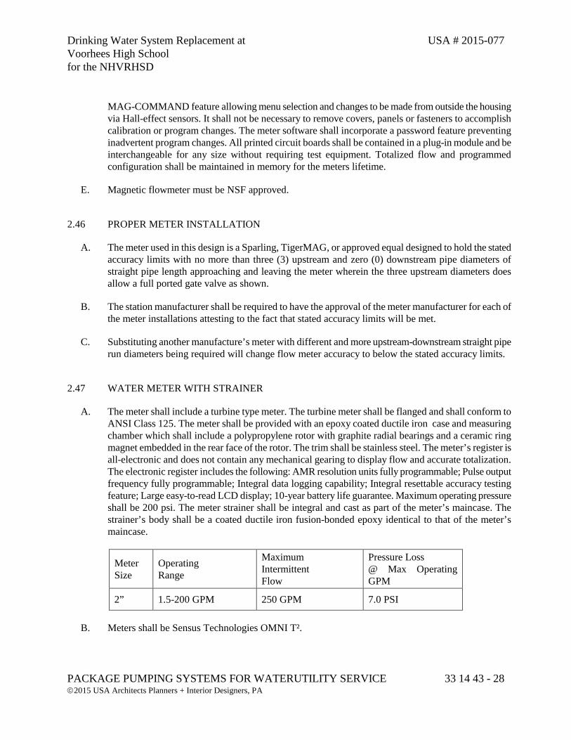
Drinking Water System Replacement at USA # 2015-077 Voorhees High School for the NHVRHSD
PACKAGE PUMPING SYSTEMS FOR WATERUTILITY SERVICE 33 14 43 - 28 2015 USA Architects Planners + Interior Designers, PA
MAG-COMMAND feature allowing menu selection and changes to be made from outside the housing via Hall-effect sensors. It shall not be necessary to remove covers, panels or fasteners to accomplish calibration or program changes. The meter software shall incorporate a password feature preventing inadvertent program changes. All printed circuit boards shall be contained in a plug-in module and be interchangeable for any size without requiring test equipment. Totalized flow and programmed configuration shall be maintained in memory for the meters lifetime.
E. Magnetic flowmeter must be NSF approved.
2.46 PROPER METER INSTALLATION
A. The meter used in this design is a Sparling, TigerMAG, or approved equal designed to hold the stated accuracy limits with no more than three (3) upstream and zero (0) downstream pipe diameters of straight pipe length approaching and leaving the meter wherein the three upstream diameters does allow a full ported gate valve as shown.
B. The station manufacturer shall be required to have the approval of the meter manufacturer for each of the meter installations attesting to the fact that stated accuracy limits will be met.
C. Substituting another manufacture’s meter with different and more upstream-downstream straight pipe run diameters being required will change flow meter accuracy to below the stated accuracy limits.
2.47 WATER METER WITH STRAINER
A. The meter shall include a turbine type meter. The turbine meter shall be flanged and shall conform to ANSI Class 125. The meter shall be provided with an epoxy coated ductile iron case and measuring chamber which shall include a polypropylene rotor with graphite radial bearings and a ceramic ring magnet embedded in the rear face of the rotor. The trim shall be stainless steel. The meter’s register is all-electronic and does not contain any mechanical gearing to display flow and accurate totalization. The electronic register includes the following: AMR resolution units fully programmable; Pulse output frequency fully programmable; Integral data logging capability; Integral resettable accuracy testing feature; Large easy-to-read LCD display; 10-year battery life guarantee. Maximum operating pressure shall be 200 psi. The meter strainer shall be integral and cast as part of the meter’s maincase. The strainer’s body shall be a coated ductile iron fusion-bonded epoxy identical to that of the meter’s maincase.
Meter Size
Operating Range
Maximum Intermittent Flow
Pressure Loss @ Max Operating GPM
2” 1.5-200 GPM 250 GPM 7.0 PSI
B. Meters shall be Sensus Technologies OMNI T².
Drinking Water System Replacement at USA # 2015-077 Voorhees High School for the NHVRHSD
PACKAGE PUMPING SYSTEMS FOR WATERUTILITY SERVICE 33 14 43 - 29 2015 USA Architects Planners + Interior Designers, PA
2.48 HYDRO-PNEUMATIC TANK
A. The station shall be complete with one (1) ASME approved bladder type hydro-pneumatic storage tank. The storage tank volume will be a minimum of 792 gallons with a maximum working pressure of 250 psi.
B. The hydro-pneumatic storage tank shall feature deep drawn steel upper and lower domes with side shell construction specifically designed for bladder type storage tanks. Storage tank welding shall be carefully done to eliminate rough spots and sharp edges. The storage tank base shall be designed so as to permit free airflow to prevent moisture from accumulating beneath the storage tank.
C. The hydro-pneumatic storage tank shall have a heavy-duty butyl bladder that effectively separates the air chamber from the water chamber. The shape of the bladder shall conform exactly to the shell configuration and shall be of seamless construction meeting FDA requirements for potable water. The bladder shall be replaceable.
D. The hydro-pneumatic storage vessel shall be as manufactured by Wessels 3000S-HP, or approved equal.
2.49 STATIC MIXER
A. The stations shall include static mixers. The mixers shall be 316 stainless steel and mounted in Schedule 40 steel piping with flanged ends. The mixers shall be mounted as shown on the plan sheet.
B. The static mixers shall be Koflo Corporation, or approved equal.
2.50 LIQUID CAUSTIC SODA FEED SYSTEM
A. Within the compartment set up for chemical feed, the station manufacturer shall provide the complete metering pump and pump control system backboard mounted on rigid polypropylene sheeting with the necessary plumbing and accessories so the solution, in volume proportional to flow from the well pump.
B. Positive Displacement Pumps:
1. The chemical feed pump shall be a 30 gpd peristaltic pump that is self-priming under maximum line pressure. The maximum output rate shall be up to 1.25 GPH at pressures to 75 PSI (8.6 Bar).
2. The pump shall be supplied with a variable speed DC motor with turndown ratio of 100:1.
3. Tubing shall meet FDA 21 CFR requirements for food contact applications.
4. Built-in failure sensors to include tube failure detection by detecting fluid pressure loss in the pump head.
Drinking Water System Replacement at USA # 2015-077 Voorhees High School for the NHVRHSD
PACKAGE PUMPING SYSTEMS FOR WATERUTILITY SERVICE 33 14 43 - 30 2015 USA Architects Planners + Interior Designers, PA
5. Pump control inputs to include at a minimum: 4-20mA inputs, pulse inputs for remote external speed control and 0-30 VDC I contact closure, remote start/stop.
6. The digital touch pad and backlit are to be LCD, displaying motor speed, input signal values, service and alarm status.
7. Two precision machined squeeze rollers and two alignment rollers shall be used for optimum accuracy and tube life.
8. The heavy duty rotor shall be a single piece of plastic with no metal springs or hinges to eliminate corrosion.
9. An optional flow verification sensor shall be included on the discharge of the pump. Flow Sensor shall be wired directly to the chemical feed pump. The pump shall automatically stop if chemical should fail to inject.
C. Calibration Column:
1. A clear PVC bodied calibration column shall be provided. Calibration column shall be composed of 100ml graduated cylinder with 2ml divisions and .5” NPT threaded top and bottom.
D. Pulsation Dampener:
1. A 10 cubic inch PVC bodied pulsation dampener shall be provided with viton elastomers and .5” NPT bottom connection for each metering pump. Pulsation dampener shall be capable of operating at pressures to 200 PSI and shall be provided with pressure gauge and bladder air fill assembly.
E. Pressure Gauge:
1. A diaphragm protected, 0-300PSI, 2.5” stainless steel bodied, glycerin filled pressure gauge shall be provided to monitor chemical feed system pressure. A PVC bodied, gauge protector with viton diaphragm shall be provided to prevent process fluid from entering the gauge. The space between the gauge and the diaphragm shall be vacuum filled with glycerin to hydraulically transfer system pressure to gauge.
F. Storage Tank:
1. There shall be provided one (1) – 55 gallon tank assembly.
2. The day tank shall be vented from the lid and out through the exterior wall of the station using a chemical resistant vent hose.

Drinking Water System Replacement at USA # 2015-077 Voorhees High School for the NHVRHSD
PACKAGE PUMPING SYSTEMS FOR WATERUTILITY SERVICE 33 14 43 - 31 2015 USA Architects Planners + Interior Designers, PA
2.51 LIQUID SODIUM HYPOCHLORITE FEED SYSTEM
A. Within the compartment set up for chemical feed, the station manufacturer shall provide the complete metering pump and pump control system backboard mounted on rigid polypropylene sheeting with the necessary plumbing and accessories so the solution, in volume proportional to flow from the well pump.
B. Positive Displacement Pumps:
1. The chemical feed pump shall be a 30 gpd peristaltic pump that is self-priming under maximum line pressure. The maximum output rate shall be up to 1.25 GPH at pressures to 75 PSI (8.6 Bar).
2. The pump shall be supplied with a variable speed DC motor with turndown ratio of 100:1.
3. Tubing shall meet FDA 21 CFR requirements for food contact applications.
4. Built-in failure sensors to include tube failure detection by detecting fluid pressure loss in the pump head.
5. Pump control inputs to include at a minimum: 4-20mA inputs, pulse inputs for remote external speed control and 0-30 VDC I contact closure, remote start/stop.
6. The digital touch pad and backlit are to be LCD, displaying motor speed, input signal values, service and alarm status.
7. Two precision machined squeeze rollers and two alignment rollers shall be used for optimum accuracy and tube life.
8. The heavy duty rotor shall be a single piece of plastic with no metal springs or hinges to eliminate corrosion.
9. An optional flow verification sensor shall be included on the discharge of the pump. Flow Sensor shall be wired directly to the chemical feed pump. The pump shall automatically stop if chemical should fail to inject.
C. Calibration Column:
1. A clear PVC bodied calibration column shall be provided. Calibration column shall be composed of 100ml graduated cylinder with 2ml divisions and .5” NPT threaded top and bottom.
D. Pulsation Dampener:
1. A 10 cubic inch PVC bodied pulsation dampener shall be provided with viton elastomers and .5” NPT bottom connection for each metering pump. Pulsation dampener shall be capable of
Drinking Water System Replacement at USA # 2015-077 Voorhees High School for the NHVRHSD
PACKAGE PUMPING SYSTEMS FOR WATERUTILITY SERVICE 33 14 43 - 32 2015 USA Architects Planners + Interior Designers, PA
operating at pressures to 200 PSI and shall be provided with pressure gauge and bladder air fill assembly.
E. Pressure Gauge:
1. A diaphragm protected, 0-300PSI, 2.5” stainless steel bodied, glycerin filled pressure gauge shall be provided to monitor chemical feed system pressure. A PVC bodied, gauge protector with viton diaphragm shall be provided to prevent process fluid from entering the gauge. The space between the gauge and the diaphragm shall be vacuum filled with glycerin to hydraulically transfer system pressure to gauge.
F. Storage Tank:
1. There shall be provided one (1) – 55 gallon tank assembly.
2. The day tank shall be vented from the lid and out through the exterior wall of the station using a chemical resistant vent hose.
2.52 CONTAINMENT PALLET
A. The shall be provided One (1) - spill containment pallet made up of a basin and a grated nested cover of sufficient size and strength to support 50 gallons of liquid hypochlorite in a drum. The basin shall have enough storage capacity as a secondary containment vessel to store the capacity of the supported vessel plus 20%.
B. The pallet and grated cover shall be of a plastic or resin based material unaffected by the prolonged contact with Liquid Sodium Hypochlorite. The pallet and grate shall be washable.
2.53 CHEMICAL FEED PIPING
A. All piping shall be Schedule 80 PVC installed by the station supplier. Piping shall be designed and installed to provide optimum pump operation and ease of maintenance. Piping layout shall prevent the entrapment of chemical between any closed sections of the system without a relief system. Piping system shall be specifically designed to reduce the entrance of bubbles to pump suction.
B. Unions shall be provided each side of pumps, pressure relief valves and back pressure sustaining valves. All valves shall be true union type. Valves shall be provided to allow drainage of chemical prior to servicing equipment. Pressure relief piping shall provide operator with visual indication of relief without spillage. Piping configuration shall vent pressure relief and calibration column to sight glass and storage tank.
Drinking Water System Replacement at USA # 2015-077 Voorhees High School for the NHVRHSD
PACKAGE PUMPING SYSTEMS FOR WATERUTILITY SERVICE 33 14 43 - 33 2015 USA Architects Planners + Interior Designers, PA
2.54 PRESSURE TESTING
A. When the station plumbing is completed, the pressure piping within the station (including valves, pumps, control valves, and fittings), connections as make up the entire system shall be hydrostatically tested at a pressure of 150 psi or a pressure equal to the lowest test pressure rating of the equipment within the tested system, whichever is lesser pressure. The test pressure shall be applied for a minimum of 20 minutes, during which time all joints, connections and seams shall be checked for leaking. Any deficiencies found shall be repaired and the system shall be retested.
B. The results of this testing shall be transmitted in writing to the Engineer prior to shipment of the station and shall note test pressure, time at full pressure and be signed by the Quality Control Manager or test technician.
2.55 ELECTRICAL DESIGN, ASSEMBLY & TEST
A. The electrical apparatus and control panel design, assembly, and installation, and the integration of component parts will be the responsibility of the manufacturer of record for this booster pumping equipment. That manufacturer shall maintain at his regular place of business a complete electrical design, assembly and test facility to assure continuity of electrical design with equipment application. Control panels designed, assembled or tested at other than the regular production facilities or by other than the regular production employees of the manufacturer of record for this booster pumping equipment will not be approved.
2.56 CONFORMANCE TO BASIC ELECTRICAL STANDARDS
A. The manufacturer of electrical control panels and their mounting and installation shall be done in strict accordance with the requirements of UL Standard 508A and the National Electrical Code (NEC), NFPA 70 latest revision so as to afford a measure of security as to the ability of the eventual owner to safely operate the equipment.
B. No exceptions to the requirements of these codes and standards will be allowed; failure to meet these requirements will be cause to remove the equipment and correct the violation.
C. The station shall comply with the requirements of Division 26 of these specifications.
2.57 U.L. LISTING
A. All service entrance, power distribution, control and starting equipment panels shall be constructed and installed in strict accordance with Underwriter's Laboratories (UL) Standard 508A "Industrial Control Equipment." The UL label shall also include an SE "Service Entrance" rating stating that the main distribution panel is suitable for use as service entrance equipment. The panels shall be shop inspected by UL, or constructed in a UL recognized facility. All panels shall bear a serialized UL label indicating acceptance under Standard 508A and under Enclosed Industrial Control Panel or Service Equipment Panel.
Drinking Water System Replacement at USA # 2015-077 Voorhees High School for the NHVRHSD
PACKAGE PUMPING SYSTEMS FOR WATERUTILITY SERVICE 33 14 43 - 34 2015 USA Architects Planners + Interior Designers, PA
B. A photocopy of the UL labels for this specific project shall be transmitted to both the project engineer and the contractor for installation within their permanent project files, prior to shipment of the equipment covered under these specifications.
2.58 E.T.L. LISTING
A. All control panels shall be E.T.L. Listed by Interek Testing Services (ITS) under the Industrial Control Panel (ICP) Category. Each completed control panel shall bear an ETL listing label stating that the panel conforms to UL STD 508A and is certified to CAN/CSA STD C22.2 NO. 14. The listing label shall include the station manufacturer's name, address and telephone number. The station manufacturer shall have quarterly inspections performed by ETL at the manufacturer's facility to ensure that the products being listed comply with the report and procedural guide for that product.
2.59 EQUIPMENT GROUNDING
A. Each electrical equipment item in the station shall be properly grounded per Section 250 of the National Electrical Code. Items to be grounded include, but are not limited to, pump motor frames, control panel, transformer, convenience receptacles, dedicated receptacle for heater, air conditioner, dehumidifier, lights, light switch, exhaust fans and pressure switches.
B. All ground wires from installed equipment shall be in conduit and shall lead back to the control panel to a copper ground buss specific for grounding purposes and so labeled. The ground buss shall be complete with a lug large enough to accept the installing electrician's bare copper earth ground wire. The bus shall serve as a bond between the earth ground and the equipment ground wires.
2.60 PANEL MOUNTING HARDWARE
A. Metal framing channel and hangers shall be used exclusively for mounting of electrical panels and electrical components except for those specifically designated otherwise.
B. When mounting panels in buildings with ¾” plywood interior sheathing, certain panels and components may be mounted by screwing these devices into the wall, The maximum weight of a panel mounted with four lag screws cannot exceed 250#. The lag screws must either be 5/16” or 3/8” diameter and be fully threaded.
2.61 ELECTRICAL SERVICE
A. The electrical service provided for this station will be 480 volt, 3 phase, 60 Hertz, 4 wire.
Drinking Water System Replacement at USA # 2015-077 Voorhees High School for the NHVRHSD
PACKAGE PUMPING SYSTEMS FOR WATERUTILITY SERVICE 33 14 43 - 35 2015 USA Architects Planners + Interior Designers, PA
2.62 ELECTRICAL DISTRIBUTION PANEL
A. The distribution panel shall be a single section, bolt-on panelboard, bottom feed, surface mount, SE rated, NEMA 1 enclosure for three phase, three wire, 480 VAC Delta power and with copper bus. Circuit Breakers are rated for 10 KAIC.
B. The main circuit breaker shall be rated for 100 amp service.
C. The lighting panelboard shall be three phase 120/208, 100 amps mains, with copper bus.
D. The distribution panel shall be complete with the following branch circuit breakers:
One (1) 3-pole, 100 amp main breaker; Two (2) 3-pole, 35 amp domestic pump motor breakers; One (1) 3-pole, 20 amp well pump motor breaker; One (1) 3-pole, 30 amp surge protection breaker One (1) 3-pole, 15 amp phase monitor breaker; One (1) 3-pole, 25 amp primary transformer breaker; One (1) 3-pole, 30 amp HVAC breaker.
E. Nameplates will be provided in etched phenolic.
2.63 SECONDARY CIRCUIT BREAKER (LIGHTING) PANEL
A. All secondary circuit breakers shall be incorporated into one (1), separate NEMA 1 circuit breaker panel.
B. There shall be provided, thermal-magnetic trip circuit breakers as follows:
One (1) Transformer Breaker, Secondary Side, 80 amps; Eighteen (18) Auxiliary Circuit Breakers, as follows: 1. 1p,15amp Controls 2. 1p,15amp Dialer 3. 1p,15amp Lights 4. 1p,20amp Convenience Outlets 5. 1p,20amp Generator Block Heater 6. 1p,15amp Dehumidifier 7. 2p,20amp Heater 8. 1p,15amp Ventilation Fan 9. 1p, 20amp Chemical Feed Systems 10. 1p, 20 Amp, Spare 11. 1p, 20Amp, Spare
Drinking Water System Replacement at USA # 2015-077 Voorhees High School for the NHVRHSD
PACKAGE PUMPING SYSTEMS FOR WATERUTILITY SERVICE 33 14 43 - 36 2015 USA Architects Planners + Interior Designers, PA
2.64 ELECTRICAL APPARATUS - CONTROL PANEL
A. All relays, controls, and the PLC shall incorporated into one (1) NEMA 1 control panel.
2.65 ELECTROMECHANICAL CONTACTOR MOTOR STARTERS
A. Where designated, those motors shall be controlled by using combination electromechanical contactor motor starters. The motor starters device shall be combination motor starters and overload protection devices as full voltage, non-reversing designated for AC motor starting being rated for continuous duty.
B. The operational voltage shall be 480 volts, three phase.
C. The electromechanical combination motor starters shall be NEMA rated.
D. Control voltage shall be 120 VAC.
2.66 ELECTRICAL APPARATUS - ADJUSTABLE FREQUENCY DRIVES
A. This specification is to cover a complete Variable Frequency motor Drive (VFD) consisting of a pulse width modulated (PWM) inverter designed for use on a standard NEMA Design B induction motor.
B. The VFD package as specified herein shall be UL listed as a complete assembly and enclosed in an integrated UL type 1 enclosure, assembled and tested by the manufacturer in an ISO9001 facility. The VFD tolerated voltage window shall allow the VFD to operate from a line of +30% nominal, and -35% nominal voltage as a minimum.
C. All VFDs shall have the same customer interface, including digital display, and keypad, regardless of horsepower rating. The keypad shall be removable, capable of remote mounting and allow for uploading and downloading of parameter settings as an aid for start-up of multiple VFDs.
D. The keypad shall include Hand-Off Auto selections and manual speed control. The drive shall incorporate bumpless transfer of speed reference when switching between Hand and Auto modes. There shall be fault reset and Help buttons on the keypad. The Help button shall include on-line assistance for programming and troubleshooting.
E. There shall be a built-in time clock in the VFD keypad. The clock shall have a battery backup with 10 years minimum life span. The clock shall be used to date and time stamp faults and record operating parameters at the time of fault. The clock shall also be programmable to control start/stop functions, constant speeds, PID parameter sets and output relays. The VFD shall have a digital input that allows an override to the time clock (when in the off mode) for a programmable time frame. There shall be four (4) separate, independent timer functions that have both weekday and weekend settings.
F. The VFDs shall utilize pre-programmed application macros specifically designed to facilitate start-up. The Application Macros shall provide on command to reprogram all parameters and customer
Drinking Water System Replacement at USA # 2015-077 Voorhees High School for the NHVRHSD
PACKAGE PUMPING SYSTEMS FOR WATERUTILITY SERVICE 33 14 43 - 37 2015 USA Architects Planners + Interior Designers, PA
interfaces for a particular application to reduce programming time. The VFD shall have two user macros to allow the end-user to create and save custom settings.
G. The VFD shall have cooling fans that are designed for easy replacement. Operating temperature will be monitored and used to cycle the fans on and off as required. The VFD shall be capable of starting into a coasting load (forward or reverse) up to full speed and accelerate of decelerate to setpoint without safety tripping or component damage (flying start).
H. The VFD shall have the ability to automatically restart after an over-current, over-voltage, under-voltage, or loss of input signal protective trip. The number of restart attempts, trial time, and time between attempts shall be programmable.
I. The overloading rating of the drive shall be 110% of its normal duty current rating for one (1) minute every ten (10) minutes, 130% overload for two (2) seconds. The minimum FLA rating shall exceed the values in the NEC/UL table 430-150 for 4-pole motors. The FLA rating of the VFD shall exceed the FLA of the motor it controls by a minimum of 5%.
J. The VFD shall have an integral 5% impedance line reactor to reduce the harmonics to the power line and to add protection from AC line transients. Each VFD shall include a line reactor regardless of the inclusion of a DC choke in the VFD.
K. The VFD shall include a coordinated AC transient protection system consisting of 4-120 joule rated MOVs (phase to phase and phase to ground), a capacitor clamp, and 5% impedance reactors.
L. The VFD shall be capable of sensing a loss of load (broken belt/broken coupling) and signal the loss of load condition. Relay outputs shall include programmable time displays that will allow for drive acceleration from zero speed without signaling a false underload condition.
M. If the input reference (4-20mA or 2-10V) is lost, the VFD shall give the user the option of either (1) stopping and displaying a fault, (2) running at a programmable preset speed, (3) hold the VFD speed based on the last good reference received, or (4) cause a warning to be issued, as selected by the user.
N. The VFD shall have programmable Sleep and Wake up functions to allow the drive to be started and stopped from the level of process feedback signal.
O. All VFD to have the following adjustments: 1. Three (3) programmable critical frequency lockout ranges to prevent the VFD from operating the
load continuously at an unstable speed. 2. Two (2) PID Setpoint controllers shall be standard in the drive, allowing pressure or flow signals
to be connected to the VFD, using the microprocessor in the VFD for the closed loop control. 3. Two (2) programmable analog inputs shall accept current or voltage signals. 4. Two (2) programmable analog outputs (0-20mA or 4-20mA). 5. Six (6) programmable digital inputs for maximum flexibility in interfacing with external devices.
6. Three (3) programmable digital Form-C relay outputs. 7. Seven (7) programmable preset speeds.
Drinking Water System Replacement at USA # 2015-077 Voorhees High School for the NHVRHSD
PACKAGE PUMPING SYSTEMS FOR WATERUTILITY SERVICE 33 14 43 - 38 2015 USA Architects Planners + Interior Designers, PA
8. Two (2) independently adjustable accel and decel ramps with 1 - 1800 seconds adjustable time ramps.
9. The VFD shall include a motor flux optimization circuit that will automatically reduce applied motor voltage to the motor to optimize energy consumption and audible motor noise.
10. The VFD shall include a carrier frequency control circuit that reduces the carrier frequency based on actual VFD temperature that allows the highest carrier frequency without derating the VFD or operating at high carrier frequency only at low speeds.
11. The VFD shall include password protection against parameter changes.
P. The VFD shall have programmable Sleep and Wake up functions to allow the drive to be started and stopped from the level of process feedback signal.
Q. The Keypad shall include a backlit LCD display. The display shall be in complete English words for programming and fault diagnostics (alpha-numeric codes are not acceptable). All applicable operating values shall be capable of being displayed in engineering (user) units. A minimum of three operating values shall be capable of being displayed at all times.
R. The VFD shall have an RS-485 port as standard. The standard protocols shall be Modbus, Johnson Controls N2 bus, and Siemens Building Technologies FLN. Each individual drive shall have the protocol in the base VFD. All protocols shall be certified by the governing authority. Serial communications capabilities shall include, but not be limited to; run-stop control, speed set adjustments, current limit, accel/decel time adjustments, and lock and unlock the keypad. The drive shall have the capability of allowing the DDC to monitor feedback such as process variable feedback, output speed/frequency, current (in amps), percent torque, power (kW), kilowatt hours (resettable), operating hours (resettable), and drive temperature. The DDC shall also be capable of monitoring the VFD relay output status, digital input status, and all analog input and analog output valves. All diagnostic warning and fault information shall be transmitted over the serial communications bus. Remote VFD fault reset shall be possible. The following additional status indicates and settings shall be transmitted over the serial communications buss - keypad Hand or Auto selected, bypass selected, the ability to change the PID setpoint. A minimum of 15 field parameters shall be capable of being monitored. The VFD shall allow the DDC to control the drive’s digital and analog outputs via the serial interface. This control shall be independent of any VFD function.
S. All VFDs shall include EMI/RFI filters. The onboard filters shall allow the VFD assembly to be CE Marked and the VFD shall meet product standard EN 61800-3 for the First Environment restricted level.
T. All VFDs through 50 HP shall be protected from input and output power mis-wiring. The VFD shall sense this condition and display an alarm on the keypad.
U. The variable frequency drive units shall be ABB Model ACH550, or approved equal.
2.67 ELECTRICAL POWER TRANSFORMER
A. 480 volts primary, 120/208 volt secondary, three phase power for the auxiliary circuits within the scope of each booster station shall be obtained by use of a 15 KVA dry, step down transformer. The
Drinking Water System Replacement at USA # 2015-077 Voorhees High School for the NHVRHSD
PACKAGE PUMPING SYSTEMS FOR WATERUTILITY SERVICE 33 14 43 - 39 2015 USA Architects Planners + Interior Designers, PA
transformer shall be wall mounting type, in a NEMA 3R non-ventilated weatherproof enclosure. Transformer shall operate with noise levels equal to or less than ANSI and NEMA standards. Transformer insulation shall be Class 180c. Transformer shall have copper windings.
B. The transformer shall meet the most recent standards for efficiency.
C. The unit shall be "UL" approved for indoor/outdoor application.
2.68 RACO, VERBATIM AUTOMATIC TELEPHONE DIALING ALARM
A. The dialer shall be a RACO, Verbatim automatic telephone dialing alarm, or approved equal.
B. The dialer shall have a minimum of 16 discrete inputs capacity.
2.69 ALARMS CONDITION AND OUTPUTS
A. The following alarms/status points shall be included within the booster pump station and wired back to the Automatic Telephone Dialing Alarm:
1. Unauthorized entry alarms on hatches and doors - The unauthorized entry alarm shall be a circuit driven by a door-mounted limit switch. The limit switch shall be the adjustable arm, roller contactor type which makes an internal SPST micro switch. The switch will be so mounted as to active anytime the entrance man way door is opened.
2. Pump 1 Motor Starter/VFD Failure – There shall be logic provided for detection, indication and alarm of the failure of the motor starter/controller.
3. Pump 2 Motor Starter/VFD Failure – There shall be logic provided for detection, indication and alarm of the failure of the motor starter/controller.
4. Well Pump Starter Overload/Fail.
5. Phase fail/power status alarm – The phase fail alarm shall be provided by 120 volt AC relay.
6. Low Clear Well Level – The low suction pressure alarm shall be provided by logic with input from the submersible level transmitter.
7. High Discharge Pressure alarm – The high discharge pressure alarm shall be provided by the logic with input from the discharge pressure transmitter.
8. Fire/Smoke alarm – The fire/smoke alarm shall be provided by a 120 volt AC relay controlled by a fire/smoke detector in the station as an input to the logic.
9. High/Low Station Temperature Alarm – The station high/low temperature alarm shall be provided by a 120 volt AC relay controlled by a thermostat in the station.
Drinking Water System Replacement at USA # 2015-077 Voorhees High School for the NHVRHSD
PACKAGE PUMPING SYSTEMS FOR WATERUTILITY SERVICE 33 14 43 - 40 2015 USA Architects Planners + Interior Designers, PA
10. Generator On/Off – Generator status shall be provided by generator panel as described elsewhere in these specifications.
11. Generator Alarm Condition – Indication of any alarm condition transmitted from the alarm control.
2.70 PUMP MOTOR RUN TIME METER
A. The control panel shall contain one running time meter supplied for each pump to show the cumulative number of hours of operation.
B. The meter shall be enclosed in a dust and moisture proof molded plastic case, suitable for flush mounting on the main control panel.
C. The meter dial shall register in hours and tenths of hours up to 99999.9 hours before repeating.
D. The meter shall be suitable for operation from a 115 volt, 60 cycle supply.
2.71 ELECTRICAL PHASE MONITOR
A. A phase monitor shall be supplied to protect three-phase equipment against phase loss, undervoltage and phase reversal conditions.
B. When a fault is sensed, the monitor output relay opens within two seconds or less to turn the equipment off and/or cause an audio or visual alarm. Both Delta and Wye systems may be monitored. The monitor shall have an automatic reset and shall also include an adjustable voltage delay.
C. The monitor shall have an indicator LED (glows when all conditions are normal and shall monitor phase sequence: ABC operate (will not operate CBA). The phase monitor shall be UL approved and CSA certified.
2.72 SURGE PROTECTION DEVICE
A. A secondary surge arrester shall be provided. Housing shall be Noryl and be ultrasonically sealed. Valve blocks shall be metal oxide with an insulating ceramic collar. Gap design shall be annular. The lead wire shall be permanently crimped to the upper electrode forming part of the gap structure.
B. Arresters shall be UL and CSA listed Lightning Protective Devices
2.73 ELECTRICAL CONDUIT AND WIRING
A. All service entrance conduits power and signal, shall be rigid steel conduit, individually sized to accept the inbound service conductors and telemetry/telephone.
Drinking Water System Replacement at USA # 2015-077 Voorhees High School for the NHVRHSD
PACKAGE PUMPING SYSTEMS FOR WATERUTILITY SERVICE 33 14 43 - 41 2015 USA Architects Planners + Interior Designers, PA
B. These service entrance conduits shall be installed from the main power or control panel through the capsule steel sidewall or the building floor and terminate exterior to the equipment enclosure as a thread hub. The service entrance exterior conduit connection points shall be capped or plugged for shipment.
C. All wiring within the equipment enclosure and outside of the panel enclosures shall be run in conduit except where watertight flexible conduit is properly used to connect pump drivers, fan motors, solenoid valves, limit switches, etc., where flexible connections are best utilized.
D. All power wiring shall be #12 AWG minimum. All discrete control wiring will be #14 AWG minimum.
E. Devices and appliances where furnished by the original manufacturer and being equipped with a UL approved rubber cord and plug, may be plugged into a receptacle.
F. Equipment enclosure conduits shall be rigid, heavy wall, Schedule 80 PVC with threaded connections, in minimum size 3/4" or larger, sized to handle the type, number and size of equipment conductors to be carried.
G. The conduiting shall be in compliance with Article 347 of the National Electrical Code and NEMA TC-2, Federal WC-1094A and UL-651 Underwriters Laboratory Specifications.
H. Where flexible conduit connections are necessary, the conduit used shall be Liquid-tight, flexible, totally nonmetallic, corrosion resistant, nonconductive, U.L. listed conduit sized to handle the type, number and size of equipment conductors to be carried - in compliance with Article 351 of the National Electrical Code.
I. Motor circuit conductors shall be sized for load. All branch circuit conductors supplying a single motor of one (1) horsepower or more shall have an ampacity of not less than 125 percent of the motor full load current rating, dual rated type THHN/THWN, as set forth in Article 310 and 430-B of the National Electrical Code, Schedule 310-13 for flame retardant, heat resistant thermoplastic, copper conductors in a nylon or equivalent outer covering.
J. Control and accessory wiring shall be sized for load, type MTW/AWM (Machine tool wire/appliance wiring material) as set forth in Article 310 and 670 of the National Electrical Code, Schedule 310-13 and NFPA Standard 79 for flame retardant, moisture, heat and oil resistant thermoplastic, copper conductors in compliance with NTMA and as listed by Underwriters Laboratories (AWM), except where accessories are furnished with a manufacturer supplied UL approved rubber cord and plug.
K. All raceways and conductors shall meet the requirements set forth in the following:
1. Specification Section 26 05 19 Low Voltage Electrical Conductors and Cables
2. Specification Section 26 05 33 Raceway and Boxes for Electrical Systems
Drinking Water System Replacement at USA # 2015-077 Voorhees High School for the NHVRHSD
PACKAGE PUMPING SYSTEMS FOR WATERUTILITY SERVICE 33 14 43 - 42 2015 USA Architects Planners + Interior Designers, PA
2.74 GAUGE PRESSURE TRANSMITTERS (PUMP STATION DISCHARGE)
A. Pressure transmitters shall be supplied to measure pump station discharge pressure. The transmitters shall sense gauge pressure and transmit a 4-20 mA dc signal. The instruments shall measure pressure of a predetermined span. Range is to be fully adjustable throughout using allowable span and range limits. The accuracy shall be ±0.20% of span.
B. Each transmitter shall provide an analog output and include a standard LCD with pushbuttons to provide Intelligent transmitter configuration directly from the on-board pushbuttons. The two-line digital indicator shall display the measurement in any selected units. The pushbuttons shall provide calibration of zero and span, setting of linear output, forward or reverse direction, external zero enable or disable, damping, failsafe action and local display including upper and lower range value selection.
C. All process-wetted parts of each instrument shall be Type 316L stainless steel. The transmitter shall be protected by a gasketed, weatherproof NEMA 4X enclosure. The transmitter shall be approved for use in hazardous locations (Nonincendive for Class 1 and Class II, Division 2 locations; intrinsically safe or explosion-proof for Class 1 and Class II, Division 1 locations).
D. The transmitter shall have 1/2 inch NPT female threaded tapping ports and shall be located on the discharge piping between the control valve and discharge piping exiting the pump station.
E. Each transmitter shall include a stainless steel bleed and block valve assembly to facilitate calibration and isolation of the instrument.
F. Gauge Pressure Transmitter manufacturers include Foxboro Series IGP10, Rosemount 2088G2S22A1M7B4S5, or approved equal.
2.75 SUBMERSIBLE PRESSURE TRANSMITTER (PUMP STATION CLEAR WELL)
A. Submersible pressure transmitter(s) shall be provided as indicated on the plans. The units shall be rated for permanent submersion in liquid. The unit shall be able to measure the pressure of the liquid in which the unit is submersed, or connect to a standard ¼” NPT male fitting.
B. The unit shall come complete from the factory with adequate lengths of cable rated for the duty and environment the unit is exposed to. The unit shall be housed in stainless steel (#316SS) housing.
C. Unit shall be factory calibrated for the range of operation required as defined in these specifications, plans or as directed by the Engineer. The supplier shall be responsible for verifying the required measurement range prior to ordering the unit.
D. Contractor to provide an additional submersible level transmitter for well.
E. The control panel shall accept an input from the submersible level transmitter installed in the well to track well level in control panel.
F. The unit shall be manufactured by Dwyer/Mercoid Series SBLT2, or approved equal
Drinking Water System Replacement at USA # 2015-077 Voorhees High School for the NHVRHSD
PACKAGE PUMPING SYSTEMS FOR WATERUTILITY SERVICE 33 14 43 - 43 2015 USA Architects Planners + Interior Designers, PA
2.76 ELECTRICAL DEVICES
A. Multi-position switches including Hand-Off-Automatic switches shall be oil tight, 3-position maintained and be located on the main control panel door.
B. Indicating lights shall be oil tight, with a full voltage pilot light.
C. Nameplates shall be furnished on all panel front mounted switches and lights.
D. Switches, lights and pushbuttons shall be Schneider Electric, Series XB, 22 mm, Die Cast Chrome plated devices. Pilot lights shall be with protected LED’s for 120 Vac operation as XB4BVG, pushbuttons shall be non-illuminated, momentary contact, extended lens as ZB4BL and the switches shall be 2 position maintained, 2 position right-to-left, 3 position maintained, 3 position momentary-to-center, 3 position momentary from left to center, and 3 position momentary from right to center with standard black lever as ZB4BD.
Switches
1. Pump #1, 3-position; 2. Pump #2, 3-position; 3. Well Pump, 3-position; 4. Exhaust Fan, 3-position;
Lights
1. Red – Low Clear Well Level; 2. Green – Pump #1 in Operation; 3. Green – Pump #2 in Operation; 4. Green – Well Pump in Operation.
E. The control panel door shall be complete on the interior with a stick-on transparency containing an "as-built" reproduction of the electrical control panel schematic. The wiring diagram shall be a corrected "as-built" copy & contain individual wire numbers, circuit breaker numbers, switch designation & control function explanations.
F. A flip/flop, cycle timer shall operate the fan such that the operator can select a time on and a time off. The cycle shall continuously repeat. It shall be overridden when the door to the station is opened and the light turned on.
2.77 PROGRAMMABLE LOGIC CONTROLLER (PLC) BASED EQUIPMENT CONTROL SYSTEM
A. Scope:
1. Provide one (1) complete Programmable Logic Controller (P.L.C.) based control system as described herein. The system shall employ industry standard Programmable Logic Controllers as described herein. The system shall be completely factory integrated and tested in the factory and field run-in with factory personnel.
Drinking Water System Replacement at USA # 2015-077 Voorhees High School for the NHVRHSD
PACKAGE PUMPING SYSTEMS FOR WATERUTILITY SERVICE 33 14 43 - 44 2015 USA Architects Planners + Interior Designers, PA
B. Basis-Of-Design PLC Equipment:
1. This equipment specification and related documents represent a design based on the Allen-Bradley 1400 Series Programmable Logic Controllers. Communications, interface, input/output and other peripheral devices have been proven to be 100% compatible with the Allen-Bradley equipment.
2. No other PLC equipment is acceptable unless the Engineer-of-Record provides notification of alternate system approval by addendum prior to the bid date.
2.78 GENERAL PLC SYSTEM REQUIREMENTS
A. Complete System Responsibility:
1. The Station manufacturer shall be the System Integrator and as such will assume full and complete responsibility for the Station P.L.C. Control System and related control functions and the telemetric communication for the full scope of supply.
2. This assumption of full responsibility shall include identifying all electrical, mechanical and plumbing schematics and wiring inter-connect diagrams, providing instrument installation details, preparing input/output listings, writing software, performing software and hardware integration, installation in the station at the factory, debugging, calibrating and tuning the various components and subsystems and providing training and warranty services.
B. UL Listing Requirement:
1. The system integrator shall produce panels that fully comply with Underwriters Laboratory Standard for Industrial Control Panels #508A.
2. All panels shall be UL 508A listed. The UL 508A "sticker" shall be clearly displayed in the appropriate location within the panel. The UL 508A listing shall be in the name of the equipment manufacturer.
C. System Integrator Facility & Staff:
1. The station manufacturer shall have on staff no fewer than Four (4) full time Control System Engineers who are dedicated to the development of P.L.C. programs, SCADA software, Instrumentation configuration and control logic development. The system integrator shall have no fewer than Three (3) electrical engineers on staff dedicated to the development of panel wiring diagrams, panel layouts and general electrical design.
2. The system Integrator shall have a field service department with no less than 5 fully equipped, trained and competent field service technicians able to work on any and all devices provided with this system. The system integrator shall have been in the business of providing telemetry, control and SCADA systems to the water production and water distribution market for no less than 10 years.
Drinking Water System Replacement at USA # 2015-077 Voorhees High School for the NHVRHSD
PACKAGE PUMPING SYSTEMS FOR WATERUTILITY SERVICE 33 14 43 - 45 2015 USA Architects Planners + Interior Designers, PA
3. The System Integrator shall submit a list of all personnel with title, job function, years with the company, years in this field and educational achievements with the submittal. Companies that do not meet the above requirements will not be approved.
D. Control Panel - Design, Assembly & Test:
1. The PLC panel design, assembly, the integration of component parts and startup will be the responsibility of the manufacturer of record for the factory-built water distribution equipment. That manufacturer shall maintain at its regular place of business a complete PLC design, assembly and test facility to assure continuity of control design with equipment application.
2.79 GENERAL EQUIPMENT SPECIFICATIONS FOR PLC CONTROL SYSTEMS
A. Enclosures:
1. Enclosures shall be NEMA 1 for indoor and NEMA 4 for outdoor locations. Enclosure shall be fabricated from a minimum of 14-gauge cold rolled steel with a baked enamel finish in the manufacturer's standard color. Units shall include a single gasket front door. Hinges, locking hasp and door clamping hardware shall be included.
B. Incoming Power Requirements & UPS:
1. Controls shall operate from a source of 120 volts, 1 phase, 60 Hz. Each panel shall be accompanied with an uninterruptible power supply (UPS). The UPS shall condition the power as well as provide 500 VA of power during outages. A 6-amp control power circuit breaker shall be employed as both a method of equipment protection and as a means of power disconnection. The circuit breaker shall be a single pole, thermal, magnetic type with a 10,000 Amp Interrupt Current rating. The circuit breaker shall be UL listed.
C. Power Supplies:
1. All DC power supplies required for operation shall be provided. Units shall provide sufficient voltage regulation and ripple control to assure powered components can operate within their required tolerances.
2. DC power supplies shall be linear. Switched power supplies are not acceptable. Circuit protection for power supplies shall include line and load side fuse protection.
D. Transient Voltage Surge Suppression (TVSS) – Data Communications and Signal Wiring:
1. The system manufacturer shall provide transient voltage and surge suppression for all PLC data communication devices whenever the communications cable is located outside the building in which the panel resides. This also applies to all outdoor panels with communications cables exiting the PLC panel enclosure. The TVSS unit shall be UL 497B listed. The TVSS unit shall have a maximum DC operating voltage of 9.6 VDC, a clamping voltage of 81V, and an 8 x 20
Drinking Water System Replacement at USA # 2015-077 Voorhees High School for the NHVRHSD
PACKAGE PUMPING SYSTEMS FOR WATERUTILITY SERVICE 33 14 43 - 46 2015 USA Architects Planners + Interior Designers, PA
US surge current rating of 1000 amps. The unit shall be approved for use by Allen-Bradley Company on the Allen-Bradley Data Highway communications products.
2. Transient voltage and surge suppression shall also be provided for 10-32 VDC instrumentation signal systems. The TVSS units shall be employed when the signal cable extends beyond the boundaries of the building in which the PLC panel is located. The TVSS unit shall be UL 497B listed. The TVSS unit shall have a maximum operating voltage of 32 VDC, a clamping voltage of 100V, and an 8 x 20 US surge current capability of 1000 amps.
3. TVSS units must be as manufactured by Leviton, Inc., of Little Neck, New York, Model 3803-485/DHP for PLC communications and Model 3420-009/035 for 10-32 VDC signal wiring, without exception.
E. Wiring Requirements:
1. All wiring shall be in complete conformance with the National Electrical Code, state, local and NEMA electrical standards. All incoming and outgoing wires shall be connected to numbered terminal blocks and all wiring neatly tied and fastened to chassis as required.
F. Network Data Line Surge Suppressors:
1. Provide transient surge suppressors for all leased telephone line, and Ethernet connections that are included as a part of this system. Unit shall have connection capabilities for RJ45, 100 BASE-T, 10 BASE-T, Token Ring, and RS-422 connections. The unit shall have a nominal clamping voltage of 7.5 volts and a Peak Pulse Current rating of 750 amperes. Unit shall be as manufactured by Tripp Lite, Inc., Model DNET-1.
2.80 PROGRAMMABLE LOGIC CONTROLLER (PLC) - MICROLOGIX 1400
A. Provide microprocessor-based Programmable Logic Controllers (PLC) as detailed in this specification and on the applicable plan sheets. The PLC shall be capable of use in a stand-alone configuration and also be capable of being networked into a larger system. It shall be specifically suitable for use in a telemetry system as an intelligent remote telemetry unit. The PLC shall be programmable in standard ladder logic.
B. The PLC shall have a processor and thirty-two (32) embedded discrete I/O. The I/O shall be expandable with the use of expansion I/O. The expansion I/O shall not require a "rack" in which to be mounted.
C. The program shall be stored on non-volatile Electrically Erasable Programmable Read Only Memory (EEPROM) modules. The CPU shall have 10,000 bytes (10K) user memory and perform 32 bit signed math functions. The CPU shall have integral to it, two communications ports capable of RS-232 DF-1 half, and full duplex serial communications as well as MODBUS RTU Slave protocol, and DF- 1 radio modem. The CPU also shall have a third port integral to it a communications port capable Ethernet communications. The CPU shall have on-line programming feature without interrupting the program running at the time.
Drinking Water System Replacement at USA # 2015-077 Voorhees High School for the NHVRHSD
PACKAGE PUMPING SYSTEMS FOR WATERUTILITY SERVICE 33 14 43 - 47 2015 USA Architects Planners + Interior Designers, PA
D. The PLC shall be powered from 85/265 VAC 60 Hz line power.
E. The PLC shall be U.L. listed, C-U.L. listed, CE compliant and suitable for use in Class 1, Division 2, Groups A, B, C and D environments.
F. The PLC shall be equipped with the following embedded discrete I/O:
1. 20 - 120 VAC inputs.
2. 12 - relay outputs.
G. The CPU shall have a LCD display integral to the unit for display of status and selectable information.
H. The PLC shall have expansion I/O capabilities as follows:
1. Discrete Input Modules: Discrete input modules shall be available in 8 channel configurations. The modules shall accept 20-48 VDC, 100-240 VAC signals. Modules shall have a removable terminal strip.
2. Relay Output Modules: Relay output modules shall be available in 8 channel versions. Modules shall be rated for 5-265 VAC and 5-125 VDC voltages.
3. Analog Input / Output Module: Analog input modules shall be available in 4 channel configurations, 2 inputs and 2 outputs. The modules shall be rated for input signals between 4 mA and 20 mA., or 0 – 10 VDC. The module shall employ a 12 bit analog to digital conversion chip. Outputs shall be either 0-10 VDC or 0-20 mA DC. The output digital to analog converter shall have 12 bit resolution.
The PLC shall be manufactured by Allen-Bradley Co. a division of Rockwell International being Model Micrologix 1400, series 1766.
2.81 OPERATOR INTERFACE EQUIPMENT – 7” COLOR
A. The PLC control system shall include a 7” High-Definition front panel mounted touch screen display for operator interface. The display shall have a 6.1" X 3.4” screen with 800 x 480 pixel resolution using 65K-color TFT LCD. The screen shall have no touch cells and utilize analog resistive technology. Unit shall have 64mb of operating RAM, 128mb flash, and a high-speed 400MHz processor. Unit shall have a real time clock chip as a standard option. Operator interface shall have integrated Ethernet port and shall support the Allen-Bradley Ethernet/IP protocol.
B. The color touch screen operator interface shall be manufactured by Maple Systems Inc., Everett, WA 98204, Model #HMI5070th, Silver Series. All required communication modules, cables, and accessories shall be provided for a complete and operational system.
Drinking Water System Replacement at USA # 2015-077 Voorhees High School for the NHVRHSD
PACKAGE PUMPING SYSTEMS FOR WATERUTILITY SERVICE 33 14 43 - 48 2015 USA Architects Planners + Interior Designers, PA
2.82 PROGRAMMING SOFTWARE
A. All PLC equipment supplied on this project shall be programmable in standard ladder logic. The ladder logic development and configuration software shall be the same for all PLC's listed in this specification. Equipment requiring separate program development and configuration software for each product is not acceptable.
B. The software program shall be Windows based and be Microsoft certified for use with Windows 7.
C. The software shall be able to develop the ladder logic programs, provide equipment configurations, diagnostics for both equipment and software, upload programs, download programs, and edit programs "on-line" where applicable.
D. The software shall be as manufactured by Rockwell Software, a division of Rockwell Automation, Model RS-LOGIX.
2.83 OPERATION DESCRIPTION FOR PLC BASED AND VFD CONTROLLED CONSTANT PRESSURE PUMPING SYSTEM
A. There shall be control algorithms programmed into the Programmable Logic Controller to operate the system based on an operator adjustable discharge pressure output setpoint through local setting.
B. The system shall control pump starting and stopping, the cascading of pumps and pump speed through the variable frequency drives based upon station discharge pressure with safety cutouts based upon suction pressure and pump speed. The PLC shall be programmed by personnel who are an employee of the station manufacture to insure a single source of responsibility and maintenance.
C. The PLC-VFD system shall operate automatically to adjust the output of the selected pump in order to maintain an adjustable hydro-tank pressure setpoint for the operation of the station. The pumps will pump up the pressure in the hydro-tank that will flow through the pressure reducing valve to keep a constant pressure on the outlet side of the station.
D. Pump output shall be adjusted by varying the speed at which it operates. The speed shall be controlled by a variable frequency drive (VFD) and the calculation of needed pump speed shall be performed by a programmable logic controller (PLC) which shall have input to it a signal directly proportional to the discharge pressure of the station.
E. The PLC shall employ a standard Proportional Integral and Derivative algorithm to calculate the 4-20mA speed reference output to the drives needed to maintain the station setpoint. Initially, the VFD’s shall provide ramping speed control on start and stop..
F. The pumps shall be brought on and offline in a cascading sequence as controlled by the pump selection/alternation portion of the control algorithm. Pump speed, with two or more pumps online, shall be the same for all pumps. When a pump comes online, its speed shall increase from the minimum speed while the online pump(s) speed shall be decreased, all to a speed which meets demand.
Drinking Water System Replacement at USA # 2015-077 Voorhees High School for the NHVRHSD
PACKAGE PUMPING SYSTEMS FOR WATERUTILITY SERVICE 33 14 43 - 49 2015 USA Architects Planners + Interior Designers, PA
G. Pumps going offline shall be done in the opposite manner to avoid pressure surges in the system.
H. Pump speeds shall be set at the minimum allowed for the proper motor cooling. These minimum speeds shall be set into the VFD program parameters. Once a single pump has run at the minimum speed for a set length of time, the pump will shut down and allow the system to operate off of the pressure in the hydro-tank until it reaches the low pressure set point.
I. Manual speed control can be accomplished through the use of a speed adjustment feature on the VFD unit.
J. Each unit shall have a Hand-Off-Automatic switch, speed adjustment and status.
2.84 MAJOR EQUIPMENT AT THIS SITE
A. Allen-Bradley MicroLogix 1400 PLC;
B. NEMA enclosure;
C. Submersible Pressure transmitter (2);
D. Line Pressure transmitter;
E. Complete configuration & programming;
F. Operator Interface Unit;
G. Other devices as needed to provide a complete and operable installation.
2.85 STATION EXTERIOR LIGHTING
A. An exterior light shall be provided as located on the drawing. The light shall be 50 watt CFL. Housing shall be one piece, injection molded, bronze polycarbonate. A button type photo control shall be provided.
2.86 STATION INTERIOR LIGHTING
A. There shall be one or more two-tube, 32 watt per tube, electronic start, enclosed and gasketed, forty-eight (48) inch minimum length fluorescent light fixtures installed within the equipment enclosure, as shown on the plan for this item. The light switch shall be of the night glow type and be located conveniently adjacent to the door.
B. Open fluorescent or incandescent fixtures will not be accepted.
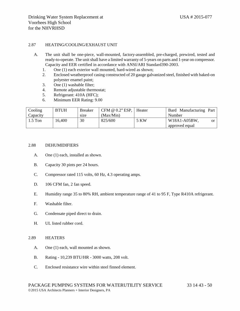
Drinking Water System Replacement at USA # 2015-077 Voorhees High School for the NHVRHSD
PACKAGE PUMPING SYSTEMS FOR WATERUTILITY SERVICE 33 14 43 - 50 2015 USA Architects Planners + Interior Designers, PA
2.87 HEATING/COOLING/EXHAUST UNIT
A. The unit shall be one-piece, wall-mounted, factory-assembled, pre-charged, prewired, tested and ready-to-operate. The unit shall have a limited warranty of 5-years on parts and 1-year on compressor. Capacity and EER certified in accordance with ANSI/ARI Standard390-2003.
1. One (1) each exterior wall mounted, hard-wired as shown; 2. Enclosed weatherproof casing constructed of 20 gauge galvanized steel, finished with baked-on
polyester enamel paint; 3. One (1) washable filter; 4. Remote adjustable thermostat; 5. Refrigerant: 410A (HFC); 6. Minimum EER Rating: 9.00
Cooling Capacity
BTUH Breaker size
CFM @ 0.2” ESP, (Max/Min)
Heater Bard Manufacturing Part Number
1.5 Ton 16,400 30 825/600 5 KW W18A1-A05BW, or approved equal
2.88 DEHUMIDIFIERS
A. One (1) each, installed as shown.
B. Capacity 30 pints per 24 hours.
C. Compressor rated 115 volts, 60 Hz, 4.3 operating amps.
D. 106 CFM fan, 2 fan speed.
E. Humidity range 35 to 80% RH, ambient temperature range of 41 to 95 F, Type R410A refrigerant.
F. Washable filter.
G. Condensate piped direct to drain.
H. UL listed rubber cord.
2.89 HEATERS
A. One (1) each, wall mounted as shown.
B. Rating - 10,239 BTU/HR - 3000 watts, 208 volt.
C. Enclosed resistance wire within steel finned element.
Drinking Water System Replacement at USA # 2015-077 Voorhees High School for the NHVRHSD
PACKAGE PUMPING SYSTEMS FOR WATERUTILITY SERVICE 33 14 43 - 51 2015 USA Architects Planners + Interior Designers, PA
D. Control - thermostat.
E. UL listed.
F. Fan forced.
G. Hard wired in conduit per UL 400-1.
2.90 CONVENIENCE GROUP - SHUTTER-MOUNTED EXHAUST FAN
A. One (1) each installed as shown.
B. Capacity each 470 CFM of free air at 0.125 inch static pressure.
C. 120 volt, 60 Hz, 1550 rpm, totally enclosed, shaded pole, sleeve bearing motors, Class A insulation.
D. Gray polyester coated steel guard.
E. Cold rolled galvanized steel frame.
F. 12" diameter, stamped aluminum, 3-blade propeller.
G. Hard wired in conduit to conduit box on motor per UL 400-1.
H. UL Listed.
I. 120 volt AC operation from wall mount thermostat and HAND/AUTO switch on main control panel.
J. One (1) 12" x 12" automatic shutter with exterior mounted, aluminum shroud and insect screen.
2.91 CONVENIENCE GROUP - MOTORIZED AIR RETURN SHUTTER
A. One (1) each installed as shown.
B. 12" x 12" 16 gauge extruded aluminum frame.
C. Aluminum blades.
D. 120 volt AC, 60 cycle, single phase electric motor.
E. Operation of shutter from start/stop of exhaust fan described above.
F. One (1) exterior mounted, aluminum shroud and insect screen.
Drinking Water System Replacement at USA # 2015-077 Voorhees High School for the NHVRHSD
PACKAGE PUMPING SYSTEMS FOR WATERUTILITY SERVICE 33 14 43 - 52 2015 USA Architects Planners + Interior Designers, PA
2.92 EMERGENCY SHOWER/EYE WASH
A. An emergency shower with eye wash shall be provided. The unit shall be heavy wall Schedule 80 hot-dip galvanized piping, with high-visibility yellow stainless steel spray head, catch basin, stainless steel pull actuators, 8” flanges for secure floor mounting, stay-open valve and emergency sign. Unit shall comply with ANSI Z358.1-1998.
B. Emergency shower/eye wash shall be Bradley Model S19-310UU, or approved equal.
2.93 AUTOMATIC TRANSFER SWITCH
A. There shall be space inside the pump room for the installation of an automatic transfer switch provided by the Contractor to the Pump Station manufacturer.
B. The transfer switch shall be provided to the station manufacturer in a timely manner as to not delay the shipped or completion of the station, the station manufacturer shall install the transfer switch in the station at the factory.
C. If the transfer switch is not delivered to the station manufacture in a timely manner, the site contractor will have the responsibility of installing the transfer switch in the station when the station has been delivered to the site.
PART 3 - PAYMENT
3.1 QUANTITY AND PAYMENT
A. No separate payment shall be made for this section. The cost shall be included within the various items bid in the Proposal.
PART 4 - APPENDICES
4.1 APPENDIX OF SUPPLIMENTAL SUBMITTAL FORMS
A. The following supplemental forms shall be part of the Pre-Manufactured Steel Pump Station submittal package.
1. Warrantee Statement
2. Welding Certification
Drinking Water System Replacement at USA # 2015-077 Voorhees High School for the NHVRHSD
PACKAGE PUMPING SYSTEMS FOR WATERUTILITY SERVICE 33 14 43 - 53 2015 USA Architects Planners + Interior Designers, PA
3. Corrosion Protection Statement
4. Facility Start-Up Service Statement
5. Applicable Standards and Listings Statement
6. Certificate of Compliance
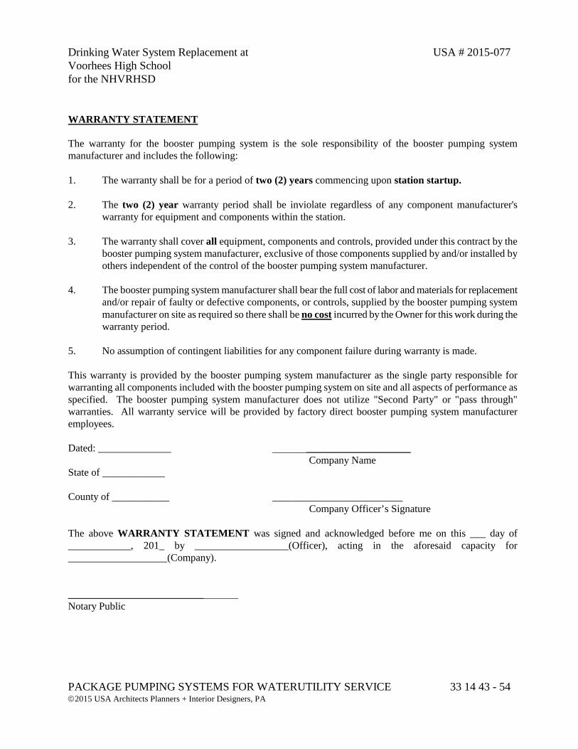
Drinking Water System Replacement at USA # 2015-077 Voorhees High School for the NHVRHSD
PACKAGE PUMPING SYSTEMS FOR WATERUTILITY SERVICE 33 14 43 - 54 2015 USA Architects Planners + Interior Designers, PA
WARRANTY STATEMENT The warranty for the booster pumping system is the sole responsibility of the booster pumping system manufacturer and includes the following: 1. The warranty shall be for a period of two (2) years commencing upon station startup. 2. The two (2) year warranty period shall be inviolate regardless of any component manufacturer's
warranty for equipment and components within the station. 3. The warranty shall cover all equipment, components and controls, provided under this contract by the
booster pumping system manufacturer, exclusive of those components supplied by and/or installed by others independent of the control of the booster pumping system manufacturer.
4. The booster pumping system manufacturer shall bear the full cost of labor and materials for replacement
and/or repair of faulty or defective components, or controls, supplied by the booster pumping system manufacturer on site as required so there shall be no cost incurred by the Owner for this work during the warranty period.
5. No assumption of contingent liabilities for any component failure during warranty is made. This warranty is provided by the booster pumping system manufacturer as the single party responsible for warranting all components included with the booster pumping system on site and all aspects of performance as specified. The booster pumping system manufacturer does not utilize "Second Party" or "pass through" warranties. All warranty service will be provided by factory direct booster pumping system manufacturer employees. Dated: ______________ ____________________ Company Name State of ____________ County of ___________ _________________________ Company Officer’s Signature The above WARRANTY STATEMENT was signed and acknowledged before me on this ___ day of ____________, 201_ by __________________(Officer), acting in the aforesaid capacity for ___________________(Company).
__________________________ Notary Public
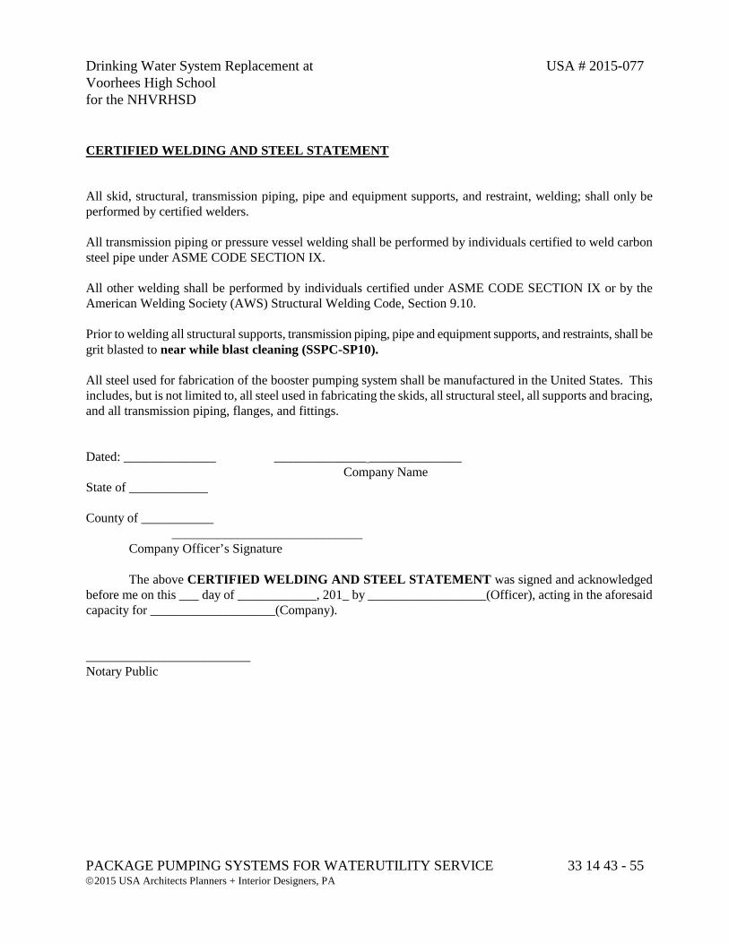
Drinking Water System Replacement at USA # 2015-077 Voorhees High School for the NHVRHSD
PACKAGE PUMPING SYSTEMS FOR WATERUTILITY SERVICE 33 14 43 - 55 2015 USA Architects Planners + Interior Designers, PA
CERTIFIED WELDING AND STEEL STATEMENT All skid, structural, transmission piping, pipe and equipment supports, and restraint, welding; shall only be performed by certified welders. All transmission piping or pressure vessel welding shall be performed by individuals certified to weld carbon steel pipe under ASME CODE SECTION IX. All other welding shall be performed by individuals certified under ASME CODE SECTION IX or by the American Welding Society (AWS) Structural Welding Code, Section 9.10. Prior to welding all structural supports, transmission piping, pipe and equipment supports, and restraints, shall be grit blasted to near while blast cleaning (SSPC-SP10). All steel used for fabrication of the booster pumping system shall be manufactured in the United States. This includes, but is not limited to, all steel used in fabricating the skids, all structural steel, all supports and bracing, and all transmission piping, flanges, and fittings. Dated: ______________ ______________ ______________ Company Name State of ____________ County of ___________ _____________________________ Company Officer’s Signature The above CERTIFIED WELDING AND STEEL STATEMENT was signed and acknowledged before me on this ___ day of ____________, 201_ by __________________(Officer), acting in the aforesaid capacity for ___________________(Company). _________________________ Notary Public
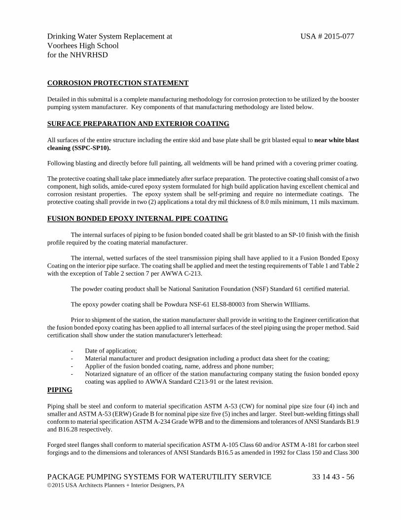
Drinking Water System Replacement at USA # 2015-077 Voorhees High School for the NHVRHSD
PACKAGE PUMPING SYSTEMS FOR WATERUTILITY SERVICE 33 14 43 - 56 2015 USA Architects Planners + Interior Designers, PA
CORROSION PROTECTION STATEMENT Detailed in this submittal is a complete manufacturing methodology for corrosion protection to be utilized by the booster pumping system manufacturer. Key components of that manufacturing methodology are listed below. SURFACE PREPARATION AND EXTERIOR COATING All surfaces of the entire structure including the entire skid and base plate shall be grit blasted equal to near white blast cleaning (SSPC-SP10). Following blasting and directly before full painting, all weldments will be hand primed with a covering primer coating. The protective coating shall take place immediately after surface preparation. The protective coating shall consist of a two component, high solids, amide-cured epoxy system formulated for high build application having excellent chemical and corrosion resistant properties. The epoxy system shall be self-priming and require no intermediate coatings. The protective coating shall provide in two (2) applications a total dry mil thickness of 8.0 mils minimum, 11 mils maximum. FUSION BONDED EPOXY INTERNAL PIPE COATING The internal surfaces of piping to be fusion bonded coated shall be grit blasted to an SP-10 finish with the finish profile required by the coating material manufacturer. The internal, wetted surfaces of the steel transmission piping shall have applied to it a Fusion Bonded Epoxy Coating on the interior pipe surface. The coating shall be applied and meet the testing requirements of Table 1 and Table 2 with the exception of Table 2 section 7 per AWWA C-213.
The powder coating product shall be National Sanitation Foundation (NSF) Standard 61 certified material.
The epoxy powder coating shall be Powdura NSF-61 ELS8-80003 from Sherwin WIlliams.
Prior to shipment of the station, the station manufacturer shall provide in writing to the Engineer certification that the fusion bonded epoxy coating has been applied to all internal surfaces of the steel piping using the proper method. Said certification shall show under the station manufacturer's letterhead: - Date of application; - Material manufacturer and product designation including a product data sheet for the coating; - Applier of the fusion bonded coating, name, address and phone number; - Notarized signature of an officer of the station manufacturing company stating the fusion bonded epoxy
coating was applied to AWWA Standard C213-91 or the latest revision. PIPING Piping shall be steel and conform to material specification ASTM A-53 (CW) for nominal pipe size four (4) inch and smaller and ASTM A-53 (ERW) Grade B for nominal pipe size five (5) inches and larger. Steel butt-welding fittings shall conform to material specification ASTM A-234 Grade WPB and to the dimensions and tolerances of ANSI Standards B1.9 and B16.28 respectively. Forged steel flanges shall conform to material specification ASTM A-105 Class 60 and/or ASTM A-181 for carbon steel forgings and to the dimensions and tolerances of ANSI Standards B16.5 as amended in 1992 for Class 150 and Class 300
Drinking Water System Replacement at USA # 2015-077 Voorhees High School for the NHVRHSD
PACKAGE PUMPING SYSTEMS FOR WATERUTILITY SERVICE 33 14 43 - 57 2015 USA Architects Planners + Interior Designers, PA
flanges.
The piping sizes shall be as shown on the drawing. Size 10 inch and below - Schedule 40 Size 12 inch and above - Standard weight (.375" wall)
All pipe welds shall be performed by certified welders employed by the booster pumping system manufacturer. As part of the equipment submittal, the pumping system manufacturer shall provide copies of the welding certificates of the employees who are to perform the pipe welds. All piping surfaces shall be prepared by sandblasting, or other abrasive blasting, prior to any welds taking place. Piping or 5" diameter and smaller may be cut by saw. Piping of 6" diameter and larger shall be bevel cut, and Oxyfuel or Plasma-arc cutting techniques shall be used to assure and facilitate bevel pipe cuts. No saw cuts or other form of abrasive cut-offs are allowed on 6" and larger diameter pipe. In all cases, short circuit transfer, spray transfer or pulse-arc transfer modes of the gas metal arc welding process shall be applied semi-automatically. When utilizing the short circuit mode, shielding gas shall be used. When utilizing the short circuit mode, shielding gas consisting of 50% carbon dioxide and 50% argon gas shall be used. When utilizing the spray or pulse-arc transfer modes, a shielding gas consisting of 5% carbon dioxide and 95% argon shall be used. In all cases, welding wire with a minimum tensile strength of 70,000 psi shall be employed. All tensile strength of 60,000 psi shall be employed. All flange welds and butt welds of equal size pipe shall be a single continuous nonstop weld around the complete circumference of the pipe. Whenever possible, vertical up weld passes will be applied to all pipe welds. No vertical down weld passes will be allowed. Completed welding assemblies shall create no internal obstruction, restriction or create any unintended sources of water deflection. Piping of six (6) inch diameter and larger shall require a minimum of two (2) weld passes to complete each weld. The first pass, or root pass, shall be applied at the bottom of the bevel cut using the short circuit transfer welding mode, and the second pass, or cap pass, shall be applied over the root pass using the spray or pulse arc transfer welding modes to insure that at a minimum the total weld thickness shall be equal to thinnest of the two (2) pieces being welded together. Dated: ______________ _____ ______________ Company Name State of ____________ County of ___________ ___________________________ Company Officer’s Signature
The above CORROSION PROTECTION SYSTEM STATEMENT was signed and acknowledged before me on this ___ day of ____________, 201_ by __________________(Officer), acting in the aforesaid capacity for ___________________(Company). ____________________________ Notary Public
Drinking Water System Replacement at USA # 2015-077 Voorhees High School for the NHVRHSD
PACKAGE PUMPING SYSTEMS FOR WATERUTILITY SERVICE 33 14 43 - 58 2015 USA Architects Planners + Interior Designers, PA
FACTORY START-UP AND SERVICE STATEMENT Start-up and warranty service shall be performed by the booster pumping system manufacturer factory direct employees. No representative, contract service organization or third party of any sort shall be directed to perform such services by the booster pumping system manufacturer.
1. Start-up and warranty service technicians shall be regular factory direct employees.
2. At least one of the following factory direct employees will perform all services and warranty work as required on the booster pump station:
EMPLOYEE NAME POSITION YEAR OF SERVICE
_________________ __________________ _______
_________________ __________________ _______
_________________ __________________ _______
_________________ __________________ _______
_________________ __________________ _______
3. One (1) or more of the Service Technicians listed above will perform the required start-up and warranty service on the booster pumping system.
4. A total of one (1) day for start-up and training on site shall be provided.
5. Start-up service to include two (2) bound O&M Manuals for the booster pumping system. 6. All start-up or service reports shall be attested to by start-up technician and representatives of
Owner or Engineer.
7. Service reports shall be distributed to:
a. Manufacturer's File b. Engineer's File c. Contractor's File d. Owner's File
Dated: ______________ ___________ ______________ Company Name State of ____________
Drinking Water System Replacement at USA # 2015-077 Voorhees High School for the NHVRHSD
PACKAGE PUMPING SYSTEMS FOR WATERUTILITY SERVICE 33 14 43 - 59 2015 USA Architects Planners + Interior Designers, PA
County of ___________ _________________________ Company Officer’s Signature The above FACTORY START-UP AND SERVICE STATEMENT was signed and acknowledged before me on this ___ day of ____________, 201_ by __________________(Officer), acting in the aforesaid capacity for ___________________(Company). Notary Public
Drinking Water System Replacement at USA # 2015-077 Voorhees High School for the NHVRHSD
PACKAGE PUMPING SYSTEMS FOR WATERUTILITY SERVICE 33 14 43 - 60 2015 USA Architects Planners + Interior Designers, PA
APPLICABLE STANDARDS AND LISTINGS This booster pumping system will be manufactured to pertinent sections of the following standards and listings:
1) Underwriters Laboratories, Inc. (UL) ULQCZJ, UL508, UL508SE, UL58,
2) National Electric Code (NEC) Compliance
3) American Water Works Association
4) Electrical Testing Laboratory (ETL)
5) American National Standards Institute (ANSI)
6) American Society for Testing and Materials (ASTM)
7) American Welding Society (AWS)
8) American Society of Mechanical Engineers (ASME)
9) Society For Protective Coatings (SSPC) (formally Steel Structures Painting Council)
10) National Sanitation Foundation (NSF) 11) Ten States Standard
Dated: ______________ _____________________ Company Name State of ____________ County of ___________ _________________________ Company Officer’s Signature The above APPLICABLE STANDARDS AND LISTING STATEMENT was signed and acknowledged before me on this ______day of ____________, 201_ by __________________(Officer), acting in the aforesaid capacity for ___________________(Company). ____________________________ Notary Public
Drinking Water System Replacement at USA # 2015-077 Voorhees High School for the NHVRHSD
PACKAGE PUMPING SYSTEMS FOR WATERUTILITY SERVICE 33 14 43 - 61 2015 USA Architects Planners + Interior Designers, PA
CERTIFICATION OF COMPLIANCE We the undersigned booster pumping system manufacturer have reviewed the plans and specifications and herein certify we will bid the project as specified without exception or deviation. We the undersigned booster pumping system manufacturer understand conditional proposals will not be accepted and submission of a proposal by a booster pumping system manufacturer, will constitute an incontrovertible representation by the booster pumping system manufacturer that without exception the proposal is premised upon all work as required by these plans and specifications and will be completed fully as specified. We the undersigned booster pumping system manufacturer understand the Contract Documents are the final authority for acceptance of the work provided. We understand the booster pumping system manufacturer is required to provide the required design with bid submittals. We the undersigned booster pumping system manufacturer understand the Engineer and Owner shall be considered the sole judge of the merits of the manufacturers design with bid submittal. We the undersigned booster pumping system manufacturer understand we are eligible to offer equipment proposals for this work provided no exceptions of deviations are taken to the plan design and product specifications and provided we strictly abides by the requirements set forth in the complete design with bid submittal. We the undersigned booster pumping system manufacturer, understand award of the contract for this work will not be based solely on price. Overall booster pumping system design, price, qualification of the bidder, qualification(s) of subcontractors, and the demonstrated intent by the bidder to adhere to all aspects of these performance plans and specifications will all be factors in determining the award.
We the undersigned booster pumping system manufacturer understand this is a performance specification format. Liability for the design and performance of the booster pumping system, telemetry, and SCADA controls as specified herein will remain with the booster system manufacturer. It is the responsibility of the booster system manufacturer to fully understand the application as specified herein and to design and manufacture, the booster pumping system and telemetry / SCADA controls to the specified quality standard, to perform as required by the Engineer and Owner. Dated: ______________ _______ ______________ Company Name State of ____________ County of ___________ _________________________ Company Officer’s Signature The above Certification of Compliance was signed and acknowledged before me on this ___ day of ____________, 201_ by __________________(Officer), acting in the aforesaid capacity for ___________________(Company). ___________________________ Notary Public


![STOMATOLOGIJA-PROGRAM[1] - Veterinarski fakultet9:05 - 9:45 - 10:30 11:15- 12:00 - 12:45 - 14:00 - 15:00 15:30 9:05 9:45 10:30 11:15 12:00 12:45 14:00 15:00 15:30 16:30 v free' WSAVA](https://img.pdfslide.us/doc/110x75/5e5bdea38af09b4c2866f8b9/stomatologija-program1-veterinarski-fakultet-905-945-1030-1115-1200.jpg)