Embed Size (px)
Citation preview
Metra. The World’s Best Kits.® MetraOnline.com © COPYRIGHT 2020 METRA ELECTRONICS CORPORATION REV. 6/17/20 INST99-9233B
I N S TA L L AT I O N I N S T R U C T I O N S99-9233B
Attention! Let the vehicle sit with the key out of the ignition for a few minutes before removing the factory radio. When testing the aftermarket equipment, ensure that all factory equipment is connected before cycling the key to ignition.
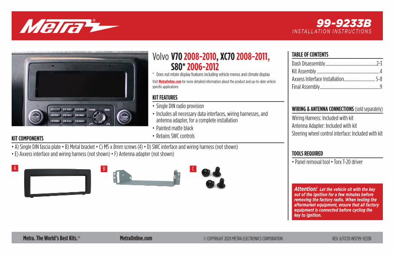
KIT FEATURES• Single DIN radio provision • Includes all necessary data interfaces, wiring harnesses, and
antenna adapter, for a complete installation• Painted matte black• Retains SWC controlsKIT COMPONENTS
• A) Single DIN fascia plate • B) Metal bracket • C) M5 x 8mm screws (4) • D) SWC interface and wiring harness (not shown)• E) Axxess interface and wiring harness (not shown) • F) Antenna adapter (not shown) TOOLS REQUIRED
• Panel removal tool • Torx T-20 driver
TABLE OF CONTENTS
Dash Disassembly ...............................................2-3Kit Assembly ..........................................................4Axxess Interface Installation ............................. 5-8Final Assembly .......................................................9
WIRING & ANTENNA CONNECTIONS (sold separately)
Wiring Harness: Included with kitAntenna Adapter: Included with kitSteering wheel control interface: Included with kit
A B C
Volvo V70 2008-2010, XC70 2008-2011, S80* 2006-2012* Does not retain display features including vehicle menus and climate display
Visit MetraOnline.com for more detailed information about the product and up-to-date vehicle specific applications
386.257.1187 | MetraOnline.com2
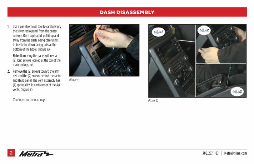
1. Use a panel removal tool to carefully pry the silver radio panel from the center console. Once separated, pull it up and away from the dash, being careful not to break the down facing tabs at the bottom of the bezel. (Figure A)
Note: Removing the panel will reveal (2) long screws located at the top of the main radio panel.
2. Remove the (2) screws toward the arm rest and the (2) screws behind the radio and HVAC panel. The vent assembly has (4) spring clips in each corner of the A/C vents. (Figure B)
Continuedonthenextpage (FigureB)
(FigureA)
DASH DISASSEMBLY
REV. 6/17/2020 INST99-9233B 3
(FigureD) (FigureF)
(FigureC) (FigureE)
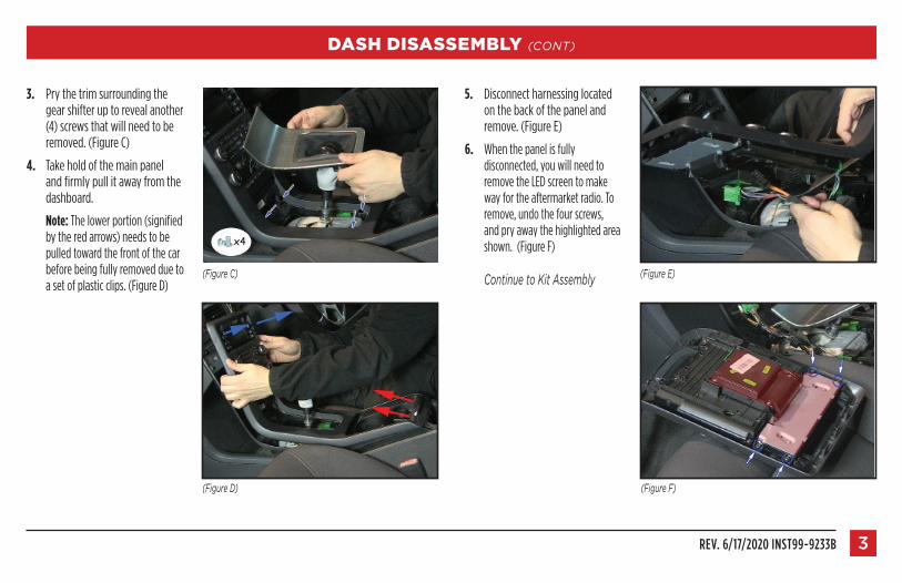
3. Pry the trim surrounding the gear shifter up to reveal another (4) screws that will need to be removed. (Figure C)
4. Take hold of the main panel and firmly pull it away from the dashboard.
Note: The lower portion (signified by the red arrows) needs to be pulled toward the front of the car before being fully removed due to a set of plastic clips. (Figure D)
5. Disconnect harnessing located on the back of the panel and remove. (Figure E)
6. When the panel is fully disconnected, you will need to remove the LED screen to make way for the aftermarket radio. To remove, undo the four screws, and pry away the highlighted area shown. (Figure F)
ContinuetoKitAssembly
DASH DISASSEMBLY (CONT)
386.257.1187 | MetraOnline.com4
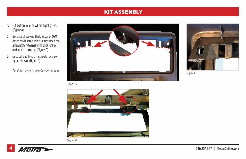
1. Cut bottom of clips where highlighted. (Figure A)
2. Because of varying thicknesses of OEM dashboards some vehicles may need the area circled v to make the clips locate and lock in correctly. (Figure B)
3. Once cut and filed trim should look like figure shown. (Figure C)
ContinuetoAxxessInterfaceInstallation
(FigureA)
(FigureC)
(FigureB)
KIT ASSEMBLY
REV. 6/17/2020 INST99-9233B 5
AXXESS INTERFACE INSTALLATION
INTERFACE FEATURES
INTERFACE COMPONENTS• 9233B interface• 9233B harness• Fiber-optic Loop Bypass• Chime Box• SWC interface• Female 3.5mm connector with stripped leads
TOOLS REQUIRED
• Crimping tool and connectors, or solder gun, solder, and heat shrink • Tape • Wire cutter • Zip ties
TABLE OF CONTENTS
Connections ................................................................................................................................... 6Installation .................................................................................................................................... 7Programming ................................................................................................................................ 8LED Feedback ................................................................................................................................ 8Final Assembly .............................................................................................................................. 9
• Provides accessory power• Retains audio/phone† controls on the steering wheel• Retains vehicle personalization and setting menus• Provides NAV outputs (parking brake, reverse, speed sense)• OE amplifier retention• Micro-B USB updatable
† Radio dependent
386.257.1187 | MetraOnline.com6
From the 9233B harness to the aftermarket radio:
• Connect the Black wire to the ground wire.
• Connect the Yellow wire to the battery wire.
• Connect the Red wire to the accessory wire.
Note: There will be an accessory wire from the SWC harness to connect as well.
• Connect the Blue wire to the amplifier turn-on wire.
• If the aftermarket radio has an illumination wire, connect the Orange wire to it.
• Connect the Brown wire to the mute wire.
Thefollowing(3)wiresareonlyformultimedia/navigationradiosthatrequirethesewires.
• Connect the Blue/Pink wire to the speed sense wire.
• Connect the Green/Purple wire to the reverse wire.
• Connect the Light Green wire to the parking brake wire.
From the SWC harness to the aftermarket radio: This harness is to be used if the vehicle is equipped with steering wheel controls. • Connect the Red wire to the accessory wire. • For the radios listed below: Connect the female 3.5mm connector with stripped leads, to the
male 3.5mm SWC jack from the SWC harness. Any remaining wires tape off and disregard: • Eclipse: Connect the steering wheel control wire, normally Brown, to the Brown/White
wire from the connector. Then connect the remaining steering wheel control wire, normally Brown/White, to the Brown wire from the connector.
• Metra OE: Connect the steering wheel control Key 1 wire (Gray) to the Brown wire. • Kenwood or select JVC with a steering wheel control wire: Connect the Blue/Yellow
wire to the Brown wire. Note: If the Kenwood radio auto detects as a JVC, manually set the radio type to Kenwood.
Refer to the Changing Radio Type document available at axxessinterfaces.com. • XITE: Connect the steering wheel control SWC-2 wire from the radio to the Brown wire. • Parrot Asteroid Smart or Tablet: Connect the 3.5mm jack into the AX-SWC-PARROT (sold
separately). Then connect the 4-pin connector from the AX-SWC-PARROT to the radio. Note: The radio must have rev. 2.1.4 or higher software. • Universal “2 or 3 wire” radio: Connect the steering wheel control wire, referred to
as Key-A or SWC-1, to the Brown wire from the connector. Then connect the remaining steering wheel control wire, referred to as Key-B or SWC-2, to the Brown/White wire from the connector. If the radio comes with a third wire for ground, disregard this wire.
Note: After the interface has been programmed to the vehicle, refer to the manual provided with the radio for assigning the SWC buttons. Contact the radio manufacturer for more info.
• For all other radios: Connect the 3.5mm jack from the SWC harness into the jack from the aftermarket radio designated for an external steering wheel control interface. Please refer to the aftermarket radios manual if in doubt as to where the 3.5mm jack should connect to.
CONNECTIONS

REV. 6/17/2020 INST99-9233B 7
INSTALLATION
With the key in the off position:
1. Connect the 9233B harness to the interface.
2. Connect the SWC harness to the SWC interface, and then to the 9233B interface.
3. Connect the fiber-optic loop provided with the kit, this will retain the OE amplifier.
4. The OE amplifier is located under the passenger seat. You will need to run the long harness from the radio down the passenger side of the vehicle. Remove the plug marked in and plug in the harness provided.
5. Locate the factory antenna connector and USB connector in the dash and complete all necessary connections to the radio.
Attention! If retaining steering wheel controls, ensure that the SWC jack/wire is connected to the radio before proceeding. If this step is skipped, the interface will need to be reset for the steering wheel controls to function.
(FigureA)
(FigureC)
(FigureB)
386.257.1187 | MetraOnline.com8
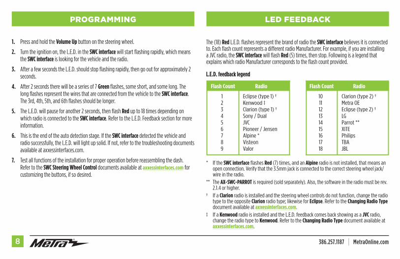
1. Press and hold the Volume Up button on the steering wheel.
2. Turn the ignition on, the L.E.D. in the SWC interface will start flashing rapidly, which means the SWC interface is looking for the vehicle and the radio.
3. After a few seconds the L.E.D. should stop flashing rapidly, then go out for approximately 2 seconds.
4. After 2 seconds there will be a series of 7 Green flashes, some short, and some long. The long flashes represent the wires that are connected from the vehicle to the SWC interface. The 3rd, 4th, 5th, and 6th flashes should be longer.
5. The L.E.D. will pause for another 2 seconds, then flash Red up to 18 times depending on which radio is connected to the SWC interface. Refer to the L.E.D. Feedback section for more information.
6. This is the end of the auto detection stage. If the SWC interface detected the vehicle and radio successfully, the L.E.D. will light up solid. If not, refer to the troubleshooting documents available at axxessinterfaces.com.
7. Test all functions of the installation for proper operation before reassembling the dash. Refer to the SWC Steering Wheel Control documents available at axxessinterfaces.com for customizing the buttons, if so desired.
PROGRAMMING LED FEEDBACK
The (18) Red L.E.D. flashes represent the brand of radio the SWC interface believes it is connected to. Each flash count represents a different radio Manufacturer. For example, if you are installing a JVC radio, the SWC interface will flash Red (5) times, then stop. Following is a legend that explains which radio Manufacturer corresponds to the flash count provided.
L.E.D. feedback legend
* If the SWC interface flashes Red (7) times, and an Alpine radio is not installed, that means an open connection. Verify that the 3.5mm jack is connected to the correct steering wheel jack/wire in the radio.
** The AX-SWC-PARROT is required (sold separately). Also, the software in the radio must be rev. 2.1.4 or higher.
† If a Clarion radio is installed and the steering wheel controls do not function, change the radio type to the opposite Clarion radio type; likewise for Eclipse. Refer to the Changing Radio Type document available at axxessinterfaces.com.
‡ If a Kenwood radio is installed and the L.E.D. feedback comes back showing as a JVC radio, change the radio type to Kenwood. Refer to the Changing Radio Type document available at axxessinterfaces.com.
Flash Count Radio
1 Eclipse (type 1) † 2 Kenwood ‡ 3 Clarion (type 1) † 4 Sony / Dual 5 JVC 6 Pioneer / Jensen 7 Alpine * 8 Visteon 9 Valor
Flash Count Radio
10 Clarion (type 2) † 11 Metra OE 12 Eclipse (type 2) † 13 LG 14 Parrot ** 15 XITE 16 Philips 17 TBA 18 JBL
REV. 6/17/2020 INST99-9233B 9
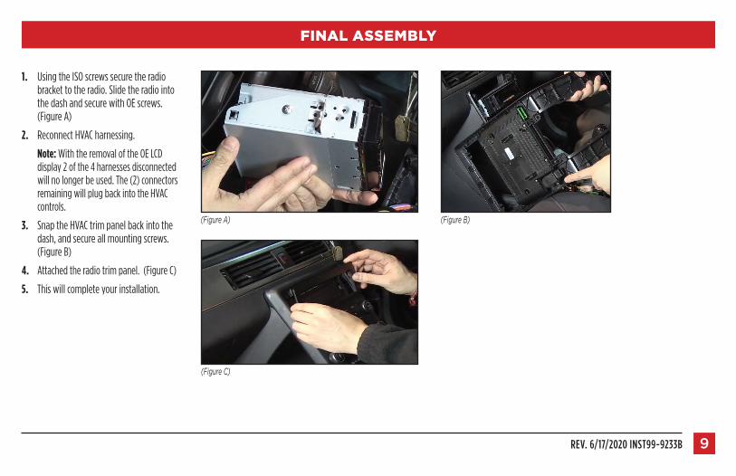
1. Using the ISO screws secure the radio bracket to the radio. Slide the radio into the dash and secure with OE screws. (Figure A)
2. Reconnect HVAC harnessing.
Note: With the removal of the OE LCD display 2 of the 4 harnesses disconnected will no longer be used. The (2) connectors remaining will plug back into the HVAC controls.
3. Snap the HVAC trim panel back into the dash, and secure all mounting screws. (Figure B)
4. Attached the radio trim panel. (Figure C)
5. This will complete your installation.
FINAL ASSEMBLY
(FigureB)(FigureA)
(FigureC)
REV. 6/17/2020 INST99-9233B 11
KNOWLEDGE IS POWEREnhance your installation and fabrication skills by enrolling in the most recognized and respected mobile electronics school in our industry.Log onto www.installerinstitute.com or call 800-354-6782 for more information and take steps toward a better tomorrow.
®
Metra recommends MECP certified technicians
Metra. The World’s Best Kits.® MetraOnline.com © COPYRIGHT 2020 METRA ELECTRONICS CORPORATION REV. 6/17/20 INST99-9233B
I N S TA L L AT I O N I N S T R U C T I O N S99-9233B
If you are having difficulties with the installation of this product, contact our Tech Support line either by phone at 386-257-1187, or email at [email protected]. Before doing so, look over the instruction booklet a second time and ensure that the installation was performed exactly as the instruction booklet is stated. Have the vehicle apart and ready to perform troubleshooting steps before contacting Metra/Axxess Tech Support.