Embed Size (px)
Citation preview
VOLVO S40
Owners Manual Web Edition

DEAR VOLVO OWNERTHANK YOU FOR CHOOSING VOLVO
We hope you will enjoy many years of driving pleasure in your Volvo.The car has been designed for the safety and comfort of you and yourpassengers. Volvo is one of the safest cars in the world. Your Volvohas also been designed to satisfy all current safety and environmentalrequirements.
In order to increase your enjoyment of the car, we recommend thatyou familiarise yourself with the equipment, instructions and mainte-nance information contained in this owner's manual.
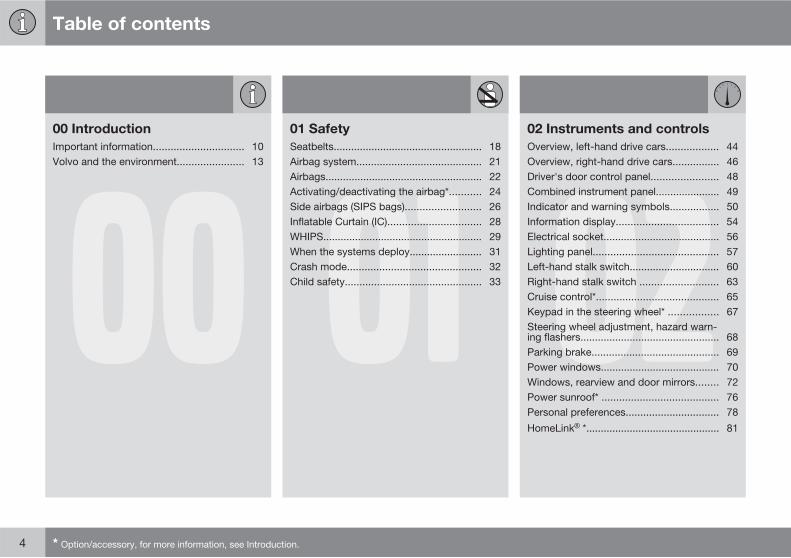
Table of contents
4 * Option/accessory, for more information, see Introduction.
0000 Introduction
Important information............................... 10Volvo and the environment....................... 13
0101 Safety
Seatbelts................................................... 18Airbag system........................................... 21Airbags...................................................... 22Activating/deactivating the airbag*........... 24Side airbags (SIPS bags).......................... 26Inflatable Curtain (IC)................................ 28WHIPS....................................................... 29When the systems deploy......................... 31Crash mode.............................................. 32Child safety............................................... 33 02
02 Instruments and controls
Overview, left-hand drive cars.................. 44Overview, right-hand drive cars................ 46Driver's door control panel....................... 48Combined instrument panel...................... 49Indicator and warning symbols................. 50Information display................................... 54Electrical socket........................................ 56Lighting panel........................................... 57Left-hand stalk switch............................... 60Right-hand stalk switch ........................... 63Cruise control*.......................................... 65Keypad in the steering wheel* ................. 67Steering wheel adjustment, hazard warn-ing flashers................................................ 68Parking brake............................................ 69Power windows......................................... 70Windows, rearview and door mirrors........ 72Power sunroof* ........................................ 76Personal preferences................................ 78
HomeLink *.............................................. 81
Table of contents
* Option/accessory, for more information, see Introduction. 5
0303 Climate control
General information on climate control..... 86Manual climate control, AC....................... 88Electronic climate control, ECC*............... 91Air distribution........................................... 94Fuel-driven engine block heater and pas-senger compartment heater*.................... 95Fuel-driven auxiliary heater* (diesel)......... 98
0404 Interior
Front seats ............................................. 102Interior lighting........................................ 104Storage spaces in the passenger com-partment ................................................. 106Rear seat................................................. 110Cargo area.............................................. 112
0505 Locks and alarm
Remote control key with key blade......... 116Active locks............................................. 119Privacy locking* ...................................... 120Keyless drive*.......................................... 122Battery in remote control key.................. 125Locking and unlocking ........................... 126Child safety locks.................................... 129Alarm* .................................................... 130
Table of contents
6 * Option/accessory, for more information, see Introduction.
0606 Starting and driving
General.................................................... 136Refuelling................................................ 138Alcoguard * ........................................... 142Starting the engine ................................. 146Starting the engine – Flexifuel................. 148Keyless drive*.......................................... 150Manual gearbox...................................... 151Automatic gearbox.................................. 152Brake system.......................................... 157DSTC – Stability and traction control sys-tem* ........................................................ 159Park Assist*............................................. 161BLIS* – Blind Spot Information System . 163Towing and recovery.............................. 166Start assistance...................................... 168Driving with a trailer................................ 169Towing equipment* ................................ 171Detachable towbar* ............................... 173Loading................................................... 177Adjusting headlamp pattern ................... 178
0707 Wheels and tyres
General.................................................... 182Tyre pressure.......................................... 186Warning triangle* and spare wheel * ...... 189Changing wheels.................................... 192Emergency puncture repair* .................. 194
0808 Car care
Cleaning.................................................. 200Touching up paintwork .......................... 204Rustproofing........................................... 205
Table of contents
* Option/accessory, for more information, see Introduction. 7
0909 Maintenance and service
Volvo service........................................... 208Self-maintenance.................................... 209Bonnet and engine compartment........... 210Oils and fluids......................................... 212Wiper blades........................................... 217Battery..................................................... 218Replacing bulbs ..................................... 220Fuses...................................................... 226 10
10 Infotainment system
General.................................................... 236Audio functions....................................... 238Radio functions....................................... 242CD functions .......................................... 247Menu structure – audio system.............. 250Phone functions*..................................... 251Menu structure – phone*......................... 258Bluetooth handsfree* ............................. 261 11
11 Specifications
Type designation..................................... 270Dimensions and weights......................... 272Engine specifications.............................. 275Engine oil................................................ 276Fluids and lubricants............................... 278Fuel......................................................... 280Electrical system..................................... 283Type approval......................................... 285Symbols in the display............................ 286
Table of contents
8
1212 Alphabetical Index
Alphabetical Index.................................. 290

Table of contents
9
Introduction
Important information
10 * Option/accessory, for more information, see Introduction.
Reading the Owner's Manual
Introduction
A good way of getting to know your new car isto read the owner's manual, ideally before yourfirst journey. This will give you the opportunityto familiarise yourself with new functions, tosee how best to handle the car in different sit-uations, and to make the best use of all thecar's features. Please pay attention to thesafety instructions contained in the manual.
The specifications, design features and illus-trations in this owner's manual are not binding.We reserve the right to make modificationswithout prior notice.© Volvo Car Corporation
Option
All types of option/accessory are marked withan asterisk*.
In addition to standard equipment, this manualalso describes options (factory fitted equip-ment) and certain accessories (retrofitted extraequipment).
The equipment described in the owner's man-ual is not available in all cars - they have dif-ferent equipment depending on adaptationsfor the needs of different markets and nationalor local laws and regulations.
In the event of uncertainty over what is stand-ard or an option/accessory, contact a Volvodealer.
Special texts
WARNING
Warning texts advise of a risk of personalinjury.
IMPORTANT
Important texts advise of a risk of materialdamage.
NOTE
NOTE texts give advice or tips that facilitatethe use of features and functions for exam-ple.
Footnote
There is footnote information in the owner'smanual that is located at the bottom of thepage. This information is an addition to the textthat it refers to via a number. If the footnoterefers to text in a table then letters are usedinstead of numbers for referral.
Message texts
There are displays in the car that show textmessages. These text messages are high-
lighted in the owner's manual by means of thetext being slightly larger and printed in grey.Examples of this are in menu texts and mes-sage texts on the information display (e.g.AUDIO SETTINGS).
Decals
The car contains different types of decal whichare designed to convey important informationin a simple and clear manner. The decals in thecar have the following descending degree ofimportance for the warning/information.
Warning for personal injury
G031590
Black ISO symbols on yellow warning field,white text/image on black message field. Usedto indicate the presence of danger which, if the
Introduction
Important information
11
warning is ignored, may result in serious per-sonal injury or fatality.
Risk of property damage
G031592
White ISO symbols and white text/image onblack or blue warning field and message field.Used to indicate the presence of danger which,if the warning is ignored, may result in damageto property.
Information
G031593
White ISO symbols and white text/image onblack message field.
NOTE
The labels shown in the owner's manual arenot provided as exact reproductions ofthose in the car. The purpose is to showtheir approximate appearance and locationin the car. The information that applies toyour car in particular is available on the labelin question in your car.
Procedure lists
Procedures where action must be taken in acertain sequence are numbered in the owner'smanual.
When there is a series of illustrations forstep-by-step instructions each step isnumbered in the same way as the corres-ponding illustration.
There are numbered lists with letters adja-cent to the series of illustrations where theorder of the instructions is not significant.
Arrows appear numbered and unnum-bered and are used to illustrate a move-ment.
If there is no series of illustrations for step-by-step instructions then the different steps arenumbered with normal numbers.
Position lists
Red circles containing a number are usedin overview images where different com-ponents are pointed out. The numberrecurs in the position list featured in con-nection with the illustration that describesthe item.
Bulleted lists
A bulleted list is used when there is a list ofpoints in the owner's manual.
Example:
Introduction
Important information
12
• Coolant
• Engine oil
To be continued
��� This symbol is located furthest down to theright when a section continues on the followingpage.
Recording data
The driving and safety systems in the car usecomputers which check and share informationwith each other on the car's function. One ormore of these computers may store informa-tion on the systems they check during normaldriving, during the course of a collision or near-collision. Stored information may be used by:
• Volvo Car Corporation
• Service or repair workshops
• Police or other authorities
• Other parties who claim legal entitlementfor access to the information or someonewho has permission from the owner toaccess the information.
Accessories and extra equipment
The incorrect connection and installation ofaccessories can negatively affect the car'selectrical system. Certain accessories onlyfunction when their associated software isinstalled in the car's computer system. Wetherefore recommend that you always contactan authorised Volvo workshop before installingaccessories which are connected to or affectthe electrical system.
Information on the Internet
At www.volvocars.com there is further infor-mation concerning your car.
Introduction
Volvo and the environment
* Option/accessory, for more information, see Introduction. 13
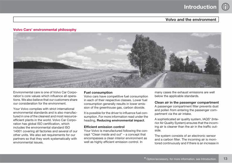
Volvo Cars' environmental philosophy
G000000
Environmental care is one of Volvo Car Corpo-ration's core values which influence all opera-tions. We also believe that our customers shareour consideration for the environment.
Your Volvo complies with strict internationalenvironmental standards and is also manufac-tured in one of the cleanest and most resource-efficient plants in the world. Volvo Car Corpo-ration has global ISO certification, whichincludes the environmental standard ISO14001 covering all factories and several of ourother units. We also set requirements for ourpartners so that they work systematically withenvironmental issues.
Fuel consumption
Volvo cars have competitive fuel consumptionin each of their respective classes. Lower fuelconsumption generally results in lower emis-sion of the greenhouse gas, carbon dioxide.
It is possible for the driver to influence fuel con-sumption. For more information read under theheading, Reducing environmental impact.
Efficient emission control
Your Volvo is manufactured following the con-cept "Clean inside and out" – a concept thatencompasses a clean interior environment aswell as highly efficient emission control. In
many cases the exhaust emissions are wellbelow the applicable standards.
Clean air in the passenger compartment
A passenger compartment filter prevents dustand pollen from entering the passenger com-partment via the air intake.
A sophisticated air quality system, IAQS* (Inte-rior Air Quality System) ensures that the incom-ing air is cleaner than the air in the traffic out-side.
The system consists of an electronic sensorand a carbon filter. The incoming air is moni-tored continuously and if there is an increase in
Introduction
Volvo and the environment
14
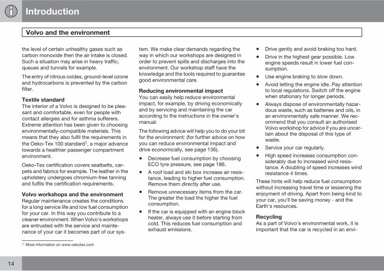
the level of certain unhealthy gases such ascarbon monoxide then the air intake is closed.Such a situation may arise in heavy traffic,queues and tunnels for example.
The entry of nitrous oxides, ground-level ozoneand hydrocarbons is prevented by the carbonfilter.
Textile standard
The interior of a Volvo is designed to be plea-sant and comfortable, even for people withcontact allergies and for asthma sufferers.Extreme attention has been given to choosingenvironmentally-compatible materials. Thismeans that they also fulfil the requirements inthe Oeko-Tex 100 standard1, a major advancetowards a healthier passenger compartmentenvironment.
Oeko-Tex certification covers seatbelts, car-pets and fabrics for example. The leather in theupholstery undergoes chromium-free tanningand fulfils the certification requirements.
Volvo workshops and the environment
Regular maintenance creates the conditionsfor a long service life and low fuel consumptionfor your car. In this way you contribute to acleaner environment. When Volvo's workshopsare entrusted with the service and mainte-nance of your car it becomes part of our sys-
tem. We make clear demands regarding theway in which our workshops are designed inorder to prevent spills and discharges into theenvironment. Our workshop staff have theknowledge and the tools required to guaranteegood environmental care.
Reducing environmental impact
You can easily help reduce environmentalimpact, for example, by driving economicallyand by servicing and maintaining the caraccording to the instructions in the owner'smanual.
The following advice will help you to do your bitfor the environment: (for further advice on howyou can reduce environmental impact anddrive economically, see page 136).
• Decrease fuel consumption by choosingECO tyre pressure, see page 186.
• A roof load and ski box increase air resis-tance, leading to higher fuel consumption.Remove them directly after use.
• Remove unnecessary items from the car.The greater the load the higher the fuelconsumption.
• If the car is equipped with an engine blockheater, always use it before starting fromcold. This reduces fuel consumption andexhaust emissions.
• Drive gently and avoid braking too hard.
• Drive in the highest gear possible. Lowengine speeds result in lower fuel con-sumption.
• Use engine braking to slow down.
• Avoid letting the engine idle. Pay attentionto local regulations. Switch off the enginewhen stationary for longer periods.
• Always dispose of environmentally hazar-dous waste, such as batteries and oils, inan environmentally safe manner. We rec-ommend that you consult an authorisedVolvo workshop for advice if you are uncer-tain about the disposal of this type ofwaste.
• Service your car regularly.
• High speed increases consumption con-siderably due to increased wind resis-tance. A doubling of speed increases windresistance 4 times.
These hints will help reduce fuel consumptionwithout increasing travel time or lessening theenjoyment of driving. Apart from being kind toyour car, you'll be saving money - and theEarth's resources.
Recycling
As a part of Volvo's environmental work, it isimportant that the car is recycled in an envi-
1 More information on www.oekotex.com
Introduction
Volvo and the environment
15
ronmentally sound manner. Almost all of thecar can be recycled. The last owner of the caris therefore requested to contact a dealer forreferral to a certified/approved recyclingfacility.
The owner's manual and theenvironment
The FSC symbol shows that the paper pulp inthis publication comes from FSC certified for-ests or other controlled sources.
16 * Option/accessory, for more information, see Introduction.
Seatbelts................................................................................................. 18Airbag system......................................................................................... 21Airbags.................................................................................................... 22Activating/deactivating the airbag*......................................................... 24Side airbags (SIPS bags)........................................................................ 26Inflatable Curtain (IC).............................................................................. 28WHIPS..................................................................................................... 29When the systems deploy....................................................................... 31Crash mode............................................................................................ 32Child safety............................................................................................. 33
SAFETY
01 Safety
Seatbelts 01
18
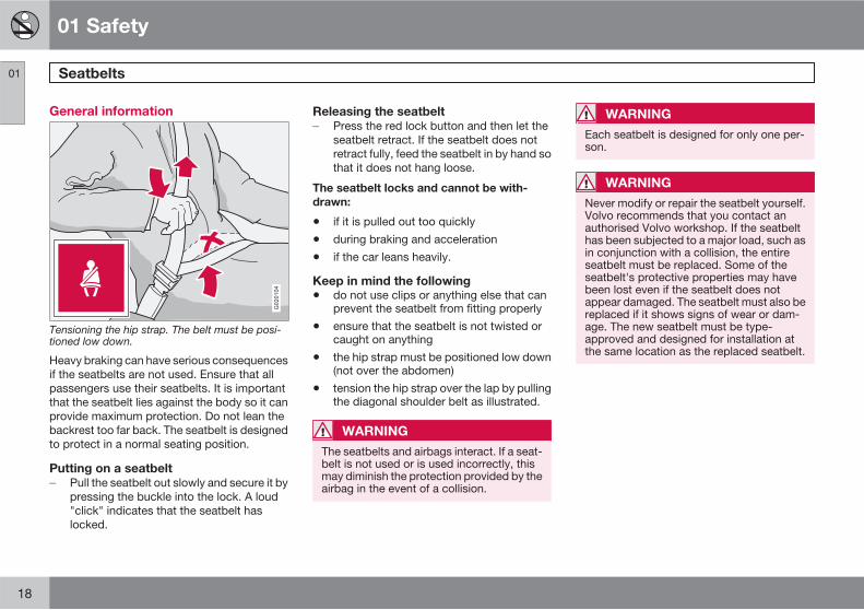
General information
G020104
Tensioning the hip strap. The belt must be posi-tioned low down.
Heavy braking can have serious consequencesif the seatbelts are not used. Ensure that allpassengers use their seatbelts. It is importantthat the seatbelt lies against the body so it canprovide maximum protection. Do not lean thebackrest too far back. The seatbelt is designedto protect in a normal seating position.
Putting on a seatbelt
� Pull the seatbelt out slowly and secure it bypressing the buckle into the lock. A loud"click" indicates that the seatbelt haslocked.
Releasing the seatbelt
� Press the red lock button and then let theseatbelt retract. If the seatbelt does notretract fully, feed the seatbelt in by hand sothat it does not hang loose.
The seatbelt locks and cannot be with-
drawn:
• if it is pulled out too quickly
• during braking and acceleration
• if the car leans heavily.
Keep in mind the following
• do not use clips or anything else that canprevent the seatbelt from fitting properly
• ensure that the seatbelt is not twisted orcaught on anything
• the hip strap must be positioned low down(not over the abdomen)
• tension the hip strap over the lap by pullingthe diagonal shoulder belt as illustrated.
WARNING
The seatbelts and airbags interact. If a seat-belt is not used or is used incorrectly, thismay diminish the protection provided by theairbag in the event of a collision.
WARNING
Each seatbelt is designed for only one per-son.
WARNING
Never modify or repair the seatbelt yourself.Volvo recommends that you contact anauthorised Volvo workshop. If the seatbelthas been subjected to a major load, such asin conjunction with a collision, the entireseatbelt must be replaced. Some of theseatbelt's protective properties may havebeen lost even if the seatbelt does notappear damaged. The seatbelt must also bereplaced if it shows signs of wear or dam-age. The new seatbelt must be type-approved and designed for installation atthe same location as the replaced seatbelt.
01 Safety
Seatbelts 01
��
19
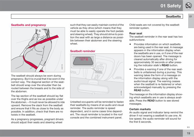
Seatbelts and pregnancy
G020105
The seatbelt should always be worn duringpregnancy. But it is crucial that it be worn in thecorrect way. The diagonal section of the seat-belt should wrap over the shoulder then berouted between the breasts and to the side ofthe abdomen.
The lap section of the seatbelt should lay flatover the thighs and as low as possible underthe abdomen. – It must never be allowed to rideupward. Remove the slack from the seatbeltand ensure that it fits as close to the body aspossible. In addition, check that there are notwists in the seatbelt.
As a pregnancy progresses, pregnant driversshould adjust their seats and steering wheel
such that they can easily maintain control of thevehicle as they drive (which means that theymust be able to easily operate the foot pedalsand steering wheel). They should strive to posi-tion the seat with as large a distance as possi-ble between their abdomen and the steeringwheel.
Seatbelt reminder
G018084
Unbelted occupants will be reminded to fastentheir seatbelts by means of an audio and visualreminder. The audio reminder is speeddependent, and in some cases time depend-ent. The visual reminder is located in the roofconsole and the combined instrument panel.
Child seats are not covered by the seatbeltreminder system.
Rear seat
The seatbelt reminder in the rear seat has twosubfunctions:
• Provides information on which seatbeltsare being used in the rear seat. A messageappears in the information display whenthe seatbelts are in use, or if one of the reardoors has been opened. The message iscleared automatically after driving forapproximately 30 seconds or after press-ing the indicator stalk's READ button.
• Provides a warning if one of the rear seat-belts is unfastened during a journey. Thiswarning takes the form of a message onthe information display along with theaudio/visual signal. The warning ceaseswhen the seatbelt is re-fastened or whenacknowledged manually by pressing theREAD button.
The message on the information display show-ing which seatbelts are in use is always avail-able. Press the READ button to see storedmessages.
Certain markets
An audio signal and indicator lamp remind thedriver if not wearing a seatbelt to use one. Atlow speed, the audio reminder will sound forthe first 6 seconds.
01 Safety
Seatbelts 01
20
Seatbelt tensioner
The front seatbelts and the two for the outerrear seats are equipped with seatbelt tension-ers. A mechanism in the seatbelt tensionertightens the seatbelt in the event of a suffi-ciently violent collision. The seatbelt then pro-vides more effective restraint for occupants.
WARNING
Never insert the tongue of the passenger'sseatbelt into the buckle on the driver's side.Always insert the tongue of the seatbelt intothe buckle on the correct side. Do not makeany damages on seatbelts nor insert anyforeign objects into a buckle. The seatbeltsand buckles would then possibly not func-tion as intended in the event of a collision.There is a risk of serous injury.
01 Safety
Airbag system 01
21
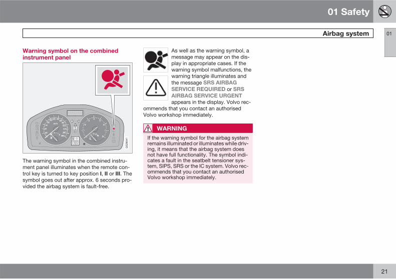
Warning symbol on the combinedinstrument panel
The warning symbol in the combined instru-ment panel illuminates when the remote con-trol key is turned to key position I, II or III. Thesymbol goes out after approx. 6 seconds pro-vided the airbag system is fault-free.
As well as the warning symbol, amessage may appear on the dis-play in appropriate cases. If thewarning symbol malfunctions, thewarning triangle illuminates andthe message SRS AIRBAG
SERVICE REQUIRED or SRS
AIRBAG SERVICE URGENT
appears in the display. Volvo rec-ommends that you contact an authorisedVolvo workshop immediately.
WARNING
If the warning symbol for the airbag systemremains illuminated or illuminates while driv-ing, it means that the airbag system doesnot have full functionality. The symbol indi-cates a fault in the seatbelt tensioner sys-tem, SIPS, SRS or the IC system. Volvo rec-ommends that you contact an authorisedVolvo workshop immediately.
01 Safety
Airbags 01
22
Airbag system
G020111
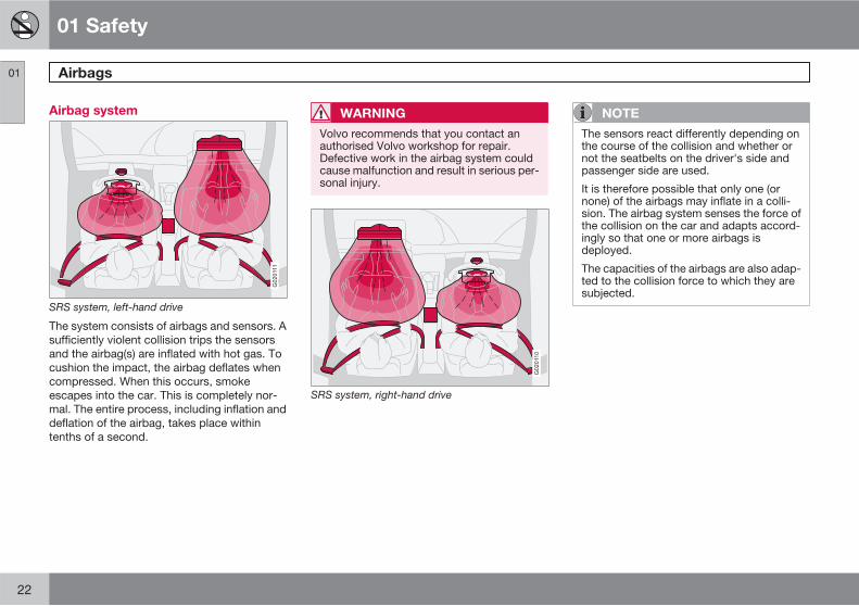
SRS system, left-hand drive
The system consists of airbags and sensors. Asufficiently violent collision trips the sensorsand the airbag(s) are inflated with hot gas. Tocushion the impact, the airbag deflates whencompressed. When this occurs, smokeescapes into the car. This is completely nor-mal. The entire process, including inflation anddeflation of the airbag, takes place withintenths of a second.
WARNING
Volvo recommends that you contact anauthorised Volvo workshop for repair.Defective work in the airbag system couldcause malfunction and result in serious per-sonal injury.
G020110
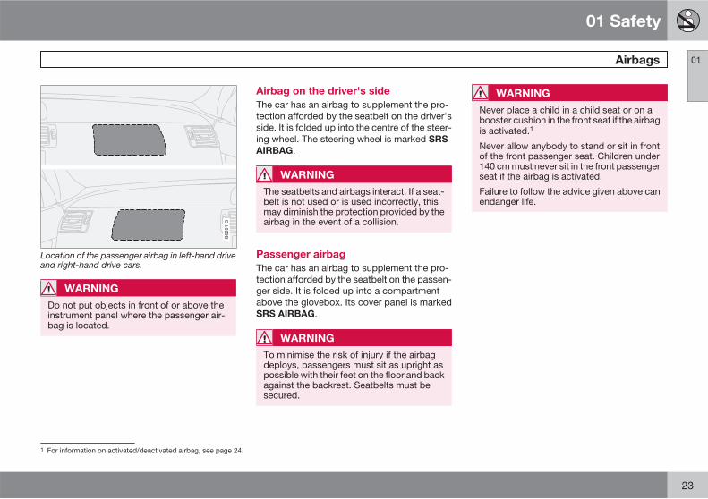
SRS system, right-hand drive
NOTE
The sensors react differently depending onthe course of the collision and whether ornot the seatbelts on the driver's side andpassenger side are used.
It is therefore possible that only one (ornone) of the airbags may inflate in a colli-sion. The airbag system senses the force ofthe collision on the car and adapts accord-ingly so that one or more airbags isdeployed.
The capacities of the airbags are also adap-ted to the collision force to which they aresubjected.
01 Safety
Airbags 01
23
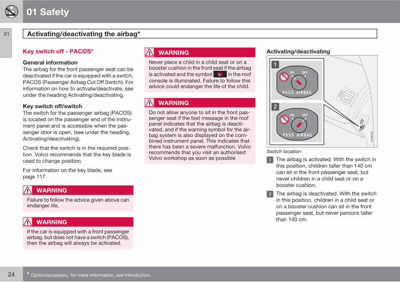
G020113
Location of the passenger airbag in left-hand driveand right-hand drive cars.
WARNING
Do not put objects in front of or above theinstrument panel where the passenger air-bag is located.
Airbag on the driver's side
The car has an airbag to supplement the pro-tection afforded by the seatbelt on the driver'sside. It is folded up into the centre of the steer-ing wheel. The steering wheel is marked SRS
AIRBAG.
WARNING
The seatbelts and airbags interact. If a seat-belt is not used or is used incorrectly, thismay diminish the protection provided by theairbag in the event of a collision.
Passenger airbag
The car has an airbag to supplement the pro-tection afforded by the seatbelt on the passen-ger side. It is folded up into a compartmentabove the glovebox. Its cover panel is markedSRS AIRBAG.
WARNING
To minimise the risk of injury if the airbagdeploys, passengers must sit as upright aspossible with their feet on the floor and backagainst the backrest. Seatbelts must besecured.
WARNING
Never place a child in a child seat or on abooster cushion in the front seat if the airbagis activated.1
Never allow anybody to stand or sit in frontof the front passenger seat. Children under140 cm must never sit in the front passengerseat if the airbag is activated.
Failure to follow the advice given above canendanger life.
1 For information on activated/deactivated airbag, see page 24.
01 Safety
Activating/deactivating the airbag* 01
24 * Option/accessory, for more information, see Introduction.
Key switch off - PACOS*
General information
The airbag for the front passenger seat can bedeactivated if the car is equipped with a switch,PACOS (Passenger Airbag Cut Off Switch). Forinformation on how to activate/deactivate, seeunder the heading Activating/deactivating.
Key switch off/switch
The switch for the passenger airbag (PACOS)is located on the passenger end of the instru-ment panel and is accessible when the pas-senger door is open, (see under the heading,Activating/deactivating).
Check that the switch is in the required posi-tion. Volvo recommends that the key blade isused to change position.
For information on the key blade, seepage 117.
WARNING
Failure to follow the advice given above canendanger life.
WARNING
If the car is equipped with a front passengerairbag, but does not have a switch (PACOS),then the airbag will always be activated.
WARNING
Never place a child in a child seat or on abooster cushion in the front seat if the airbagis activated and the symbol in the roofconsole is illuminated. Failure to follow thisadvice could endanger the life of the child.
WARNING
Do not allow anyone to sit in the front pas-senger seat if the text message in the roofpanel indicates that the airbag is deacti-vated, and if the warning symbol for the air-bag system is also displayed on the com-bined instrument panel. This indicates thatthere has been a severe malfunction. Volvorecommends that you visit an authorisedVolvo workshop as soon as possible
Activating/deactivating
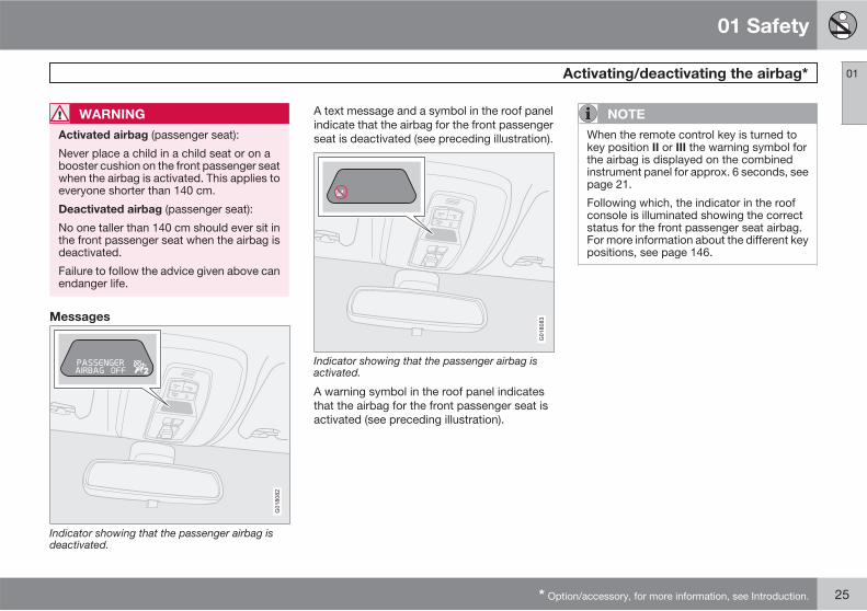
Switch location
The airbag is activated. With the switch inthis position, children taller than 140 cmcan sit in the front passenger seat, butnever children in a child seat or on abooster cushion.
The airbag is deactivated. With the switchin this position, children in a child seat oron a booster cushion can sit in the frontpassenger seat, but never persons tallerthan 140 cm.
01 Safety
Activating/deactivating the airbag* 01
* Option/accessory, for more information, see Introduction. 25
WARNING
Activated airbag (passenger seat):
Never place a child in a child seat or on abooster cushion on the front passenger seatwhen the airbag is activated. This applies toeveryone shorter than 140 cm.
Deactivated airbag (passenger seat):
No one taller than 140 cm should ever sit inthe front passenger seat when the airbag isdeactivated.
Failure to follow the advice given above canendanger life.
Messages
2
G018082
Indicator showing that the passenger airbag isdeactivated.
A text message and a symbol in the roof panelindicate that the airbag for the front passengerseat is deactivated (see preceding illustration).
G018083
Indicator showing that the passenger airbag isactivated.
A warning symbol in the roof panel indicatesthat the airbag for the front passenger seat isactivated (see preceding illustration).
NOTE
When the remote control key is turned tokey position II or III the warning symbol forthe airbag is displayed on the combinedinstrument panel for approx. 6 seconds, seepage 21.
Following which, the indicator in the roofconsole is illuminated showing the correctstatus for the front passenger seat airbag.For more information about the different keypositions, see page 146.
01 Safety
Side airbags (SIPS bags) 01
26
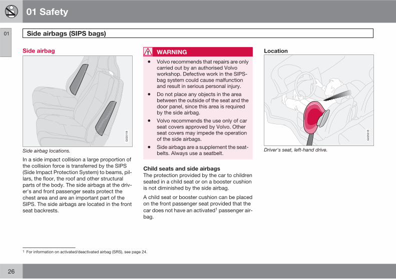
Side airbag
G020118
Side airbag locations.
In a side impact collision a large proportion ofthe collision force is transferred by the SIPS(Side Impact Protection System) to beams, pil-lars, the floor, the roof and other structuralparts of the body. The side airbags at the driv-er's and front passenger seats protect thechest area and are an important part of theSIPS. The side airbags are located in the frontseat backrests.
WARNING
• Volvo recommends that repairs are onlycarried out by an authorised Volvoworkshop. Defective work in the SIPS-bag system could cause malfunctionand result in serious personal injury.
• Do not place any objects in the areabetween the outside of the seat and thedoor panel, since this area is requiredby the side airbag.
• Volvo recommends the use only of carseat covers approved by Volvo. Otherseat covers may impede the operationof the side airbags.
• Side airbags are a supplement the seat-belts. Always use a seatbelt.
Child seats and side airbags
The protection provided by the car to childrenseated in a child seat or on a booster cushionis not diminished by the side airbag.
A child seat or booster cushion can be placedon the front passenger seat provided that thecar does not have an activated1 passenger air-bag.
Location
G025315
Driver's seat, left-hand drive.
1 For information on activated/deactivated airbag (SRS), see page 24.
01 Safety
Side airbags (SIPS bags) 01
27
G025316
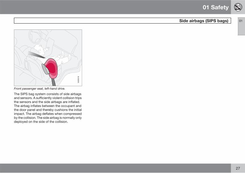
Front passenger seat, left-hand drive.
The SIPS bag system consists of side airbagsand sensors. A sufficiently violent collision tripsthe sensors and the side airbags are inflated.The airbag inflates between the occupant andthe door panel and thereby cushions the initialimpact. The airbag deflates when compressedby the collision. The side airbag is normally onlydeployed on the side of the collision.
01 Safety
Inflatable Curtain (IC) 01
28
Properties
G015265
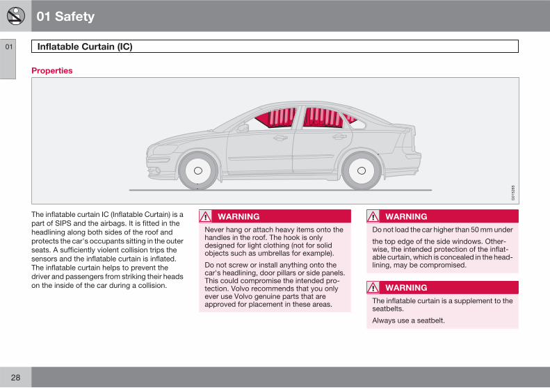
The inflatable curtain IC (Inflatable Curtain) is apart of SIPS and the airbags. It is fitted in theheadlining along both sides of the roof andprotects the car's occupants sitting in the outerseats. A sufficiently violent collision trips thesensors and the inflatable curtain is inflated.The inflatable curtain helps to prevent thedriver and passengers from striking their headson the inside of the car during a collision.
WARNING
Never hang or attach heavy items onto thehandles in the roof. The hook is onlydesigned for light clothing (not for solidobjects such as umbrellas for example).
Do not screw or install anything onto thecar's headlining, door pillars or side panels.This could compromise the intended pro-tection. Volvo recommends that you onlyever use Volvo genuine parts that areapproved for placement in these areas.
WARNING
Do not load the car higher than 50 mm under
the top edge of the side windows. Other-wise, the intended protection of the inflat-able curtain, which is concealed in the head-lining, may be compromised.
WARNING
The inflatable curtain is a supplement to theseatbelts.
Always use a seatbelt.
01 Safety
WHIPS 01
��
29
Protection against whiplash injury – WHIPS
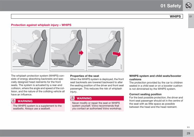
G020347
The whiplash protection system (WHIPS) con-sists of energy absorbing backrests and spe-cially designed head restraints for the frontseats. The system is actuated by a rear-endcollision, where the angle and speed of the col-lision, and the nature of the colliding vehicle allhave an influence.
WARNING
The WHIPS system is a supplement to theseatbelts. Always use a seatbelt.
Properties of the seat
When the WHIPS system is deployed, the frontseat backrests are lowered backward to alterthe seating position of the driver and front seatpassenger. This reduces the risk of whiplashinjury.
WARNING
Never modify or repair the seat or WHIPSsystem yourself. Volvo recommends thatyou contact an authorised Volvo workshop.
WHIPS system and child seats/booster
cushions
The protection provided by the car to childrenseated in a child seat or on a booster cushionis not diminished by the WHIPS system.
Correct seating position
For the best possible protection, the driver andfront seat passenger should sit in the centre ofthe seat with as little space as possiblebetween the head and the head restraint.
01 Safety
WHIPS 01
30
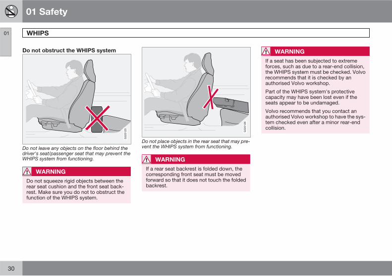
Do not obstruct the WHIPS system
G020125
Do not leave any objects on the floor behind thedriver's seat/passenger seat that may prevent theWHIPS system from functioning.
WARNING
Do not squeeze rigid objects between therear seat cushion and the front seat back-rest. Make sure you do not to obstruct thefunction of the WHIPS system.
G020126
Do not place objects in the rear seat that may pre-vent the WHIPS system from functioning.
WARNING
If a rear seat backrest is folded down, thecorresponding front seat must be movedforward so that it does not touch the foldedbackrest.
WARNING
If a seat has been subjected to extremeforces, such as due to a rear-end collision,the WHIPS system must be checked. Volvorecommends that it is checked by anauthorised Volvo workshop.
Part of the WHIPS system's protectivecapacity may have been lost even if theseats appear to be undamaged.
Volvo recommends that you contact anauthorised Volvo workshop to have the sys-tem checked even after a minor rear-endcollision.
01 Safety
When the systems deploy 01
31
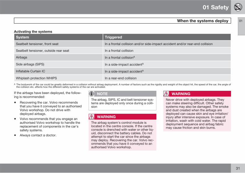
Activating the systems
System Triggered
Seatbelt tensioner, front seat In a frontal collision and/or side-impact accident and/or rear-end collision
Seatbelt tensioner, outside rear seat In a frontal collision
Airbags In a frontal collisionA
Side airbags (SIPS) In a side-impact accidentA
Inflatable Curtain IC In a side-impact accidentA
Whiplash protection WHIPS In a rear-end collision
A The bodywork of the car could be greatly deformed in a collision without airbag deployment. A number of factors such as the rigidity and weight of the object hit, the speed of the car, the angle ofthe collision etc. affects how the different safety systems of the car are activated.
If the airbags have been deployed, the follow-ing is recommended:
• Recovering the car. Volvo recommendsthat you have it conveyed to an authorisedVolvo workshop. Do not drive withdeployed airbags.
• Volvo recommends that you engage anauthorised Volvo workshop to handle thereplacement of components in the car'ssafety systems.
• Always contact a doctor.
NOTE
The airbag, SIPS, IC and belt tensioner sys-tems are deployed only once during a colli-sion
WARNING
The airbag system's control module islocated in the centre console. If the centreconsole is drenched with water or other liq-uid, disconnect the battery cables. Do notattempt to start the car since the airbagsmay deploy. Recovering the car. Volvo rec-ommends that you have it conveyed to anauthorised Volvo workshop.
WARNING
Never drive with deployed airbags. Theycan make steering difficult. Other safetysystems may also be damaged. The smokeand dust created when the airbags aredeployed can cause skin and eye irritation/injury after intensive exposure. In case ofirritation, wash with cold water. The rapiddeployment sequence and airbag fabricmay cause friction and skin burns.
01 Safety
Crash mode 01
32
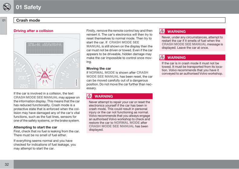
Driving after a collision
G029042
If the car is involved in a collision, the textCRASH MODE SEE MANUAL may appear onthe information display. This means that the carhas reduced functionality. Crash mode is aprotective state that is enforced when the col-lision may have damaged any of the car's vitalfunctions, such as the fuel lines, sensors forone of the safety systems, or the brake system.
Attempting to start the car
First, check that no fuel is leaking from the car.There must be no smell of fuel either.
If everything seems normal and you havechecked for indications of fuel leakage, youmay attempt to start the car.
Firstly, remove the remote control key and thenreinsert it. The car's electronics will then try toreset themselves to normal mode. Then try tostart the car. If CRASH MODE SEE
MANUAL is still shown on the display then thecar must not be driven or towed. Even if the carappears to be driveable, hidden damage maymake the car impossible to control once mov-ing.
Moving the car
If NORMAL MODE is shown after CRASH
MODE SEE MANUAL has been reset, the carcan be moved carefully out of a dangerousposition. Do not move the car further than nec-essary.
WARNING
Never attempt to repair your car or reset theelectronics yourself if the car has been incrash mode. This could result in personalinjury or the car not functioning as normal.Volvo recommends that you always engagean authorised Volvo workshop to check andrestore the car to NORMAL MODE afterCRASH MODE SEE MANUAL has beendisplayed.
WARNING
Never, under any circumstances, attempt torestart the car if it smells of fuel when theCRASH MODE SEE MANUAL message isdisplayed. Leave the car at once.
WARNING
If the car is in crash mode it must not betowed. It must be transported from its loca-tion. Volvo recommends that you have itconveyed to an authorised Volvo workshop.
01 Safety
Child safety 01
��
33
Children should sit comfortably andsafely
Volvo recommends that children travel in rear-facing child seats until as late an age as pos-sible, at least until 3-4 years of age, and thenfront-facing booster cushions/child seats up to10 years of age.
The position of a child in the car and the choiceof equipment are dictated by the child's weightand size, for more information, see page 35.
NOTE
Regulations regarding the placement ofchildren in cars vary from country to coun-try. Check what does apply.
Children of all ages and sizes must always sitcorrectly secured in the car. Never allow a childto sit on the knee of a passenger.
Volvo has child safety equipment (child seats,booster cushions & attachment devices) whichis designed for your particular car. Using Vol-vo's child safety equipment provides you withoptimum conditions for your child to travelsafely in the car. Furthermore, the child safetyequipment fits and is easy to use.
NOTE
In the event of questions when fitting childsafety products, contact the manufacturerfor clearer instructions.
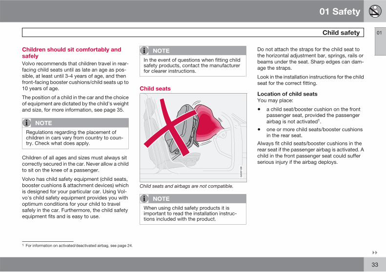
Child seats
G020128
Child seats and airbags are not compatible.
NOTE
When using child safety products it isimportant to read the installation instruc-tions included with the product.
Do not attach the straps for the child seat tothe horizontal adjustment bar, springs, rails orbeams under the seat. Sharp edges can dam-age the straps.
Look in the installation instructions for the childseat for the correct fitting.
Location of child seats
You may place:
• a child seat/booster cushion on the frontpassenger seat, provided the passengerairbag is not activated1.
• one or more child seats/booster cushionsin the rear seat.
Always fit child seats/booster cushions in therear seat if the passenger airbag is activated. Achild in the front passenger seat could sufferserious injury if the airbag deploys.
1 For information on activated/deactivated airbag, see page 24.
01 Safety
Child safety 01
34
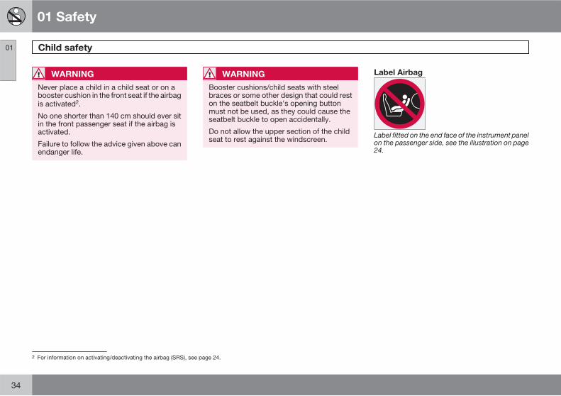
WARNING
Never place a child in a child seat or on abooster cushion in the front seat if the airbagis activated2.
No one shorter than 140 cm should ever sitin the front passenger seat if the airbag isactivated.
Failure to follow the advice given above canendanger life.
WARNING
Booster cushions/child seats with steelbraces or some other design that could reston the seatbelt buckle's opening buttonmust not be used, as they could cause theseatbelt buckle to open accidentally.
Do not allow the upper section of the childseat to rest against the windscreen.
Label Airbag
Label fitted on the end face of the instrument panelon the passenger side, see the illustration on page24.
2 For information on activating/deactivating the airbag (SRS), see page 24.
01 Safety
Child safety 01
��
35
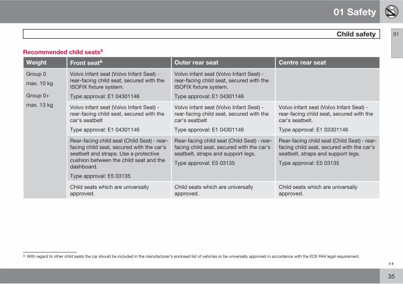
Recommended child seats3
Weight Front seatA Outer rear seat Centre rear seat
Group 0
max. 10 kg
Group 0+
max. 13 kg
Volvo infant seat (Volvo Infant Seat) -rear-facing child seat, secured with theISOFIX fixture system.
Type approval: E1 04301146
Volvo infant seat (Volvo Infant Seat) -rear-facing child seat, secured with theISOFIX fixture system.
Type approval: E1 04301146
Volvo infant seat (Volvo Infant Seat) -rear-facing child seat, secured with thecar's seatbelt
Type approval: E1 04301146
Volvo infant seat (Volvo Infant Seat) -rear-facing child seat, secured with thecar's seatbelt
Type approval: E1 04301146
Volvo infant seat (Volvo Infant Seat) -rear-facing child seat, secured with thecar's seatbelt.
Type approval: E1 03301146
Rear-facing child seat (Child Seat) - rear-facing child seat, secured with the car'sseatbelt and straps. Use a protectivecushion between the child seat and thedashboard.
Type approval: E5 03135
Rear-facing child seat (Child Seat) - rear-facing child seat, secured with the car'sseatbelt, straps and support legs.
Type approval: E5 03135
Rear-facing child seat (Child Seat) - rear-facing child seat, secured with the car'sseatbelt, straps and support legs.
Type approval: E5 03135
Child seats which are universallyapproved.
Child seats which are universallyapproved.
Child seats which are universallyapproved.
3 With regard to other child seats the car should be included in the manufacturer's enclosed list of vehicles or be universally approved in accordance with the ECE R44 legal requirement.
01 Safety
Child safety 01
36
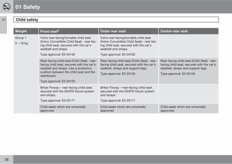
Weight Front seatA Outer rear seat Centre rear seat
Group 1
9 – 18 kg
Volvo rear-facing/turnable child seat(Volvo Convertible Child Seat) - rear-fac-ing child seat, secured with the car'sseatbelt and straps.
Type approval: E5 04192
Volvo rear-facing/turnable child seat(Volvo Convertible Child Seat) - rear-fac-ing child seat, secured with the car'sseatbelt and straps.
Type approval: E5 04192
Rear-facing child seat (Child Seat) - rear-facing child seat, secured with the car'sseatbelt and straps. Use a protectivecushion between the child seat and thedashboard.
Type approval: E5 03135
Rear-facing child seat (Child Seat) - rear-facing child seat, secured with the car'sseatbelt, straps and support legs.
Type approval: E5 03135
Rear-facing child seat (Child Seat) - rear-facing child seat, secured with the car'sseatbelt, straps and support legs.
Type approval: E5 03135
Britax Fixway – rear-facing child seat,secured with the ISOFIX fixture systemand straps.
Type approval: E5 03171
Britax Fixway – rear-facing child seat,secured with the ISOFIX fixture systemand straps.
Type approval: E5 03171
Child seats which are universallyapproved.
Child seats which are universallyapproved.
Child seats which are universallyapproved.
01 Safety
Child safety 01
��
37
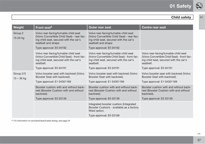
Weight Front seatA Outer rear seat Centre rear seat
Group 2
15-25 kg
Volvo rear-facing/turnable child seat(Volvo Convertible Child Seat) - rear-fac-ing child seat, secured with the car'sseatbelt and straps
Type approval: E5 04192
Volvo rear-facing/turnable child seat(Volvo Convertible Child Seat) - rear-fac-ing child seat, secured with the car'sseatbelt and straps
Type approval: E5 04192
Volvo rear-facing/turnable child seat(Volvo Convertible Child Seat) - front-fac-ing child seat, secured with the car'sseatbelt.
Type approval: E5 04191
Volvo rear-facing/turnable child seat(Volvo Convertible Child Seat) - front-fac-ing child seat, secured with the car'sseatbelt.
Type approval: E5 04191
Volvo rear-facing/turnable child seat(Volvo Convertible Child Seat) - front-fac-ing child seat, secured with the car'sseatbelt.
Type approval: E5 04191
Group 2/3
15 – 36 kg
Volvo booster seat with backrest (VolvoBooster Seat with backrest).
Type approval: E1 04301169
Volvo booster seat with backrest (VolvoBooster Seat with backrest).
Type approval: E1 04301169
Volvo booster seat with backrest (VolvoBooster Seat with backrest).
Type approval: E1 04301169
Booster cushion with and without back-rest (Booster Cushion with and withoutbackrest).
Type approval: E5 03139
Booster cushion with and without back-rest (Booster Cushion with and withoutbackrest).
Type approval: E5 03139
Booster cushion with and without back-rest (Booster Cushion with and withoutbackrest).
Type approval: E5 03139
Integrated booster cushion (IntegratedBooster Cushion) - available as a factoryfitted option.
Type approval: E5 03168
A For information on activated/deactivated airbag, see page 24.
01 Safety
Child safety 01
38 * Option/accessory, for more information, see Introduction.
WARNING
Never place a child in a child seat or on abooster cushion in the front seat if the airbagis activated4.
No one shorter than 140 cm should ever sitin the front passenger seat if the airbag isactivated.
Failure to follow the advice given above canendanger life.
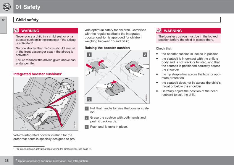
Integrated booster cushions*G015013
Volvo’s integrated booster cushion for theouter rear seats is specially designed to pro-
vide optimum safety for children. Combinedwith the regular seatbelts the integratedbooster cushion is approved for childrenweighing between 15 and 36 kg.
Raising the booster cushion
G020808
Pull that handle to raise the booster cush-ion.
Grasp the cushion with both hands andpush it backwards.
Push until it locks in place.
WARNING
The booster cushion must be in the lockedposition before the child is placed there.
Check that:
• the booster cushion in locked in position
• the seatbelt is in contact with the child'sbody and is not slack or twisted, and thatthe seatbelt is positioned correctly acrossthe shoulder
• the hip strap is low across the hips for opti-mum protection
• the seatbelt does not lie across the child'sthroat or below the shoulder
• Carefully adjust the position of the headrestraint to suit the child.
4 For information on activating/deactivating the airbag (SRS), see page 24.
01 Safety
Child safety 01
��
* Option/accessory, for more information, see Introduction. 39
WARNING
Repair or replacement should only be per-formed by a workshop. Volvo recommendsthat you contact an authorised Volvo work-shop. Do not make any modifications oradditions to the booster cushion yourself.
If an integrated booster cushion has beensubjected to a major load, such as in con-junction with a collision, the entire boostercushion must be replaced. Even if thebooster cushion appears to be undamaged,it may not afford the same level of protec-tion. The booster cushion must also bereplaced if it is heavily worn.
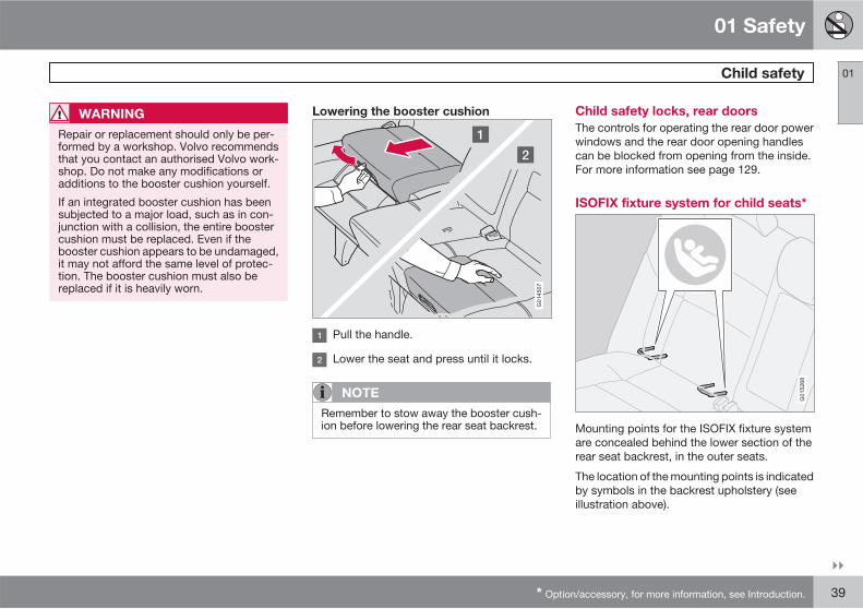
Lowering the booster cushion
G014507
Pull the handle.
Lower the seat and press until it locks.
NOTE
Remember to stow away the booster cush-ion before lowering the rear seat backrest.
Child safety locks, rear doors
The controls for operating the rear door powerwindows and the rear door opening handlescan be blocked from opening from the inside.For more information see page 129.
ISOFIX fixture system for child seats*
G015268
Mounting points for the ISOFIX fixture systemare concealed behind the lower section of therear seat backrest, in the outer seats.
The location of the mounting points is indicatedby symbols in the backrest upholstery (seeillustration above).
01 Safety
Child safety 01
40
Press the seat cushion down to access themounting points.
NOTE
The ISOFIX fixture system is an accessoryfor the passenger seat.
Always follow the manufacturer's installationinstructions when connecting a child seat tothe ISOFIX mounting points.
01 Safety
01
41
42 * Option/accessory, for more information, see Introduction.
Overview, left-hand drive cars................................................................ 44Overview, right-hand drive cars.............................................................. 46Driver's door control panel..................................................................... 48Combined instrument panel.................................................................... 49Indicator and warning symbols............................................................... 50Information display.................................................................................. 54Electrical socket...................................................................................... 56Lighting panel.......................................................................................... 57Left-hand stalk switch............................................................................. 60Right-hand stalk switch ......................................................................... 63Cruise control*........................................................................................ 65Keypad in the steering wheel* ............................................................... 67Steering wheel adjustment, hazard warning flashers............................. 68Parking brake.......................................................................................... 69Power windows....................................................................................... 70Windows, rearview and door mirrors...................................................... 72Power sunroof* ...................................................................................... 76Personal preferences.............................................................................. 78
HomeLink *............................................................................................ 81
INSTRUMENTS AND CONTROLS
02 Instruments and controls
Overview, left-hand drive cars
02
44
G01
9488
02 Instruments and controls
Overview, left-hand drive cars
02
45
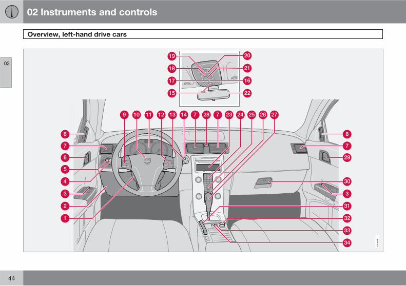
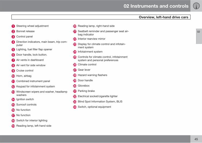
Steering wheel adjustment
Bonnet release
Control panel
Direction indicators, main beam, trip com-puter
Lighting, fuel filler flap opener
Door handle, lock button.
Air vents in dashboard
Air vent for side window
Cruise control
Horn, airbag
Combined instrument panel
Keypad for infotainment system
Windscreen wipers and washer, headlampwashers
Ignition switch
Sunroof controls
No function
No function
Switch for interior lighting
Reading lamp, left-hand side
Reading lamp, right-hand side
Seatbelt reminder and passenger seat air-bag indicator
Interior rearview mirror
Display for climate control and infotain-ment system
Infotainment system
Controls for climate control, infotainmentsystem and personal preferences
Climate control
Gear lever
Hazard warning flashers
Door handle
Glovebox
Parking brake
Electrical socket/cigarette lighter
Blind Spot Information System, BLIS
Switch, optional equipment
02 Instruments and controls
Overview, right-hand drive cars
02
46
G02
8204
02 Instruments and controls
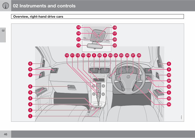
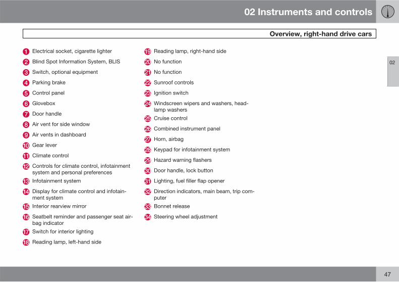
Overview, right-hand drive cars
02
47
Electrical socket, cigarette lighter
Blind Spot Information System, BLIS
Switch, optional equipment
Parking brake
Control panel
Glovebox
Door handle
Air vent for side window
Air vents in dashboard
Gear lever
Climate control
Controls for climate control, infotainmentsystem and personal preferences
Infotainment system
Display for climate control and infotain-ment system
Interior rearview mirror
Seatbelt reminder and passenger seat air-bag indicator
Switch for interior lighting
Reading lamp, left-hand side
Reading lamp, right-hand side
No function
No function
Sunroof controls
Ignition switch
Windscreen wipers and washers, head-lamp washers
Cruise control
Combined instrument panel
Horn, airbag
Keypad for infotainment system
Hazard warning flashers
Door handle, lock button
Lighting, fuel filler flap opener
Direction indicators, main beam, trip com-puter
Bonnet release
Steering wheel adjustment
02 Instruments and controls
Driver's door control panel
02
48 * Option/accessory, for more information, see Introduction.
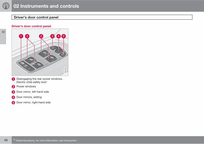
Driver's door control panel
Disengaging the rear power windows.Electric child safety lock*
Power windows
Door mirror, left-hand side
Door mirrors, setting
Door mirror, right-hand side

02 Instruments and controls
Combined instrument panel
02
49
G02
9046
Speedometer.
Direction indicators, left.
Warning symbol.
Information display – Shows information orwarning messages, outside temperatureand clock. When the outside temperatureis between +2 °C to -5 °C a snowflake illu-minates on the display. This warns of icyroads. The outside temperature gaugemay show a slightly high reading after thecar has been stationary.
Information symbol.
Direction indicator, right.
Tachometer – Indicates engine speed inthousands of revolutions per minute (rpm).
Indicator and warning symbols.
Fuel gauge, see also trip computer, page 61.
Main beam indicator.
Display – Display for automatic gear posi-tion, rain sensor, odometer, trip meter andcruise control.
Also shows gear shift indicator (GSI) andgear positions in the 1.6D DRIVe model,see page 151.
Button for trip meter – Used to measureshort distances. Short presses on the but-ton switches between the two trip metersT1 and T2. A long press (more than 2 sec-onds) resets an active trip meter to zero.
Temperature gauge - Used for the enginecooling system. A message will appear onthe display if the temperature becomes toohigh and the gauge goes into the red zone.Bear in mind that extra lights placed in frontof the air intake, for example, reduce thecooling capacity at high outside tempera-tures and high engine loads.
Indicator and warning symbols.
02 Instruments and controls
Indicator and warning symbols
02
50
Functionality check, symbols
All indicator and warning symbols1 illuminatewhen the remote control key is turned to posi-tion II before starting. This is to check that thesymbols are working. When the engine starts,all the symbols should go out except the hand-brake symbol, which only goes out when thebrake is disengaged.
If the engine does not start withinfive seconds, all symbols extin-guish except the symbols for afault in the car's emissions systemand for low oil pressure. Certainsymbols may have no function,depending on the car's specifica-tions.
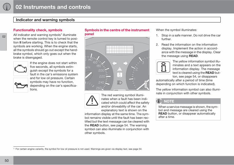
Symbols in the centre of the instrumentpanel
G030755
The red warning symbol illumi-nates when a fault has been indi-cated which could affect the safetyand/or driveability of the car. Anexplanatory text is shown on the
information display at the same time. The sym-bol remains visible until the fault has been rec-tified but the text message can be cleared withthe READ button, see page 54. The warningsymbol can also illuminate in conjunction withother symbols.
When the symbol illuminates:
1. Stop in a safe manner. Do not drive the carfurther.
2. Read the information on the informationdisplay. Implement the action in accord-ance with the message in the display. Clearthe message using READ.
The yellow information symbol illu-minates and a text appears on theinformation display. The messagetext is cleared using the READ but-ton, see page 54, or disappears
automatically after a period of time (timedepending on which function is indicated).
The yellow information symbol can also illumi-nate in conjunction with other symbols.
NOTE
When a service message is shown, the sym-bol and message are cleared using theREAD button, or disappear automaticallyafter a time.
1 For certain engine variants, the symbol for low oil pressure is not used. Warnings are given via display text, see page 54.
02 Instruments and controls
Indicator and warning symbols
02
��
* Option/accessory, for more information, see Introduction. 51
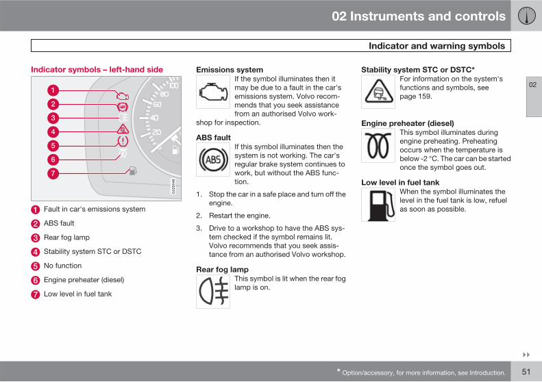
Indicator symbols – left-hand side
G029048
Fault in car's emissions system
ABS fault
Rear fog lamp
Stability system STC or DSTC
No function
Engine preheater (diesel)
Low level in fuel tank
Emissions system
If the symbol illuminates then itmay be due to a fault in the car'semissions system. Volvo recom-mends that you seek assistancefrom an authorised Volvo work-
shop for inspection.
ABS fault
If this symbol illuminates then thesystem is not working. The car'sregular brake system continues towork, but without the ABS func-tion.
1. Stop the car in a safe place and turn off theengine.
2. Restart the engine.
3. Drive to a workshop to have the ABS sys-tem checked if the symbol remains lit.Volvo recommends that you seek assis-tance from an authorised Volvo workshop.
Rear fog lamp
This symbol is lit when the rear foglamp is on.
Stability system STC or DSTC*
For information on the system'sfunctions and symbols, seepage 159.
Engine preheater (diesel)
This symbol illuminates duringengine preheating. Preheatingoccurs when the temperature isbelow -2 °C. The car can be startedonce the symbol goes out.
Low level in fuel tank
When the symbol illuminates thelevel in the fuel tank is low, refuelas soon as possible.
02 Instruments and controls
Indicator and warning symbols
02
52
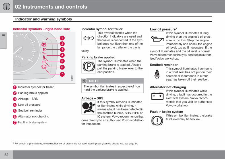
Indicator symbols – right-hand side
G029049
Indicator symbol for trailer
Parking brake applied
Airbags – SRS
Low oil pressure
Seatbelt reminder
Alternator not charging
Fault in brake system
Indicator symbol for trailer
This symbol flashes when thedirection indicators are used andthe trailer is connected. If the sym-bol does not flash then one of thelamps on the trailer or the car is
faulty.
Parking brake applied
The symbol illuminates when theparking brake is applied. Alwayspull the parking brake lever to theend position.
NOTE
The symbol illuminates irrespective of howhard the parking brake is applied.
Airbags – SRS
If this symbol remains illuminatedor illuminates while driving, itmeans a fault has been detected inthe seatbelt buckle, SRS, SIPS orIC system. Volvo recommends that
drive directly to an authorised Volvo workshopfor inspection.
Low oil pressure2
If this symbol illuminates duringdriving then the engine's oil pres-sure is too low. Stop the engineimmediately and check the engineoil level, top up if necessary. If the
symbol illuminates and the oil level is normalVolvo recommends that you contact an author-ised Volvo workshop.
Seatbelt reminder
This symbol illuminates if someonein a front seat has not put on theirseatbelt or if someone in a rearseat has taken off their seatbelt.
Alternator not charging
If this symbol illuminates whiledriving, a fault has occurred in theelectrical system. Volvo recom-mends that you visit an authorisedVolvo workshop.
Fault in brake system
If this symbol illuminates, the brakefluid level may be too low.
2 For certain engine variants, the symbol for low oil pressure is not used. Warnings are given via display text, see page 54.
02 Instruments and controls
Indicator and warning symbols
02
53
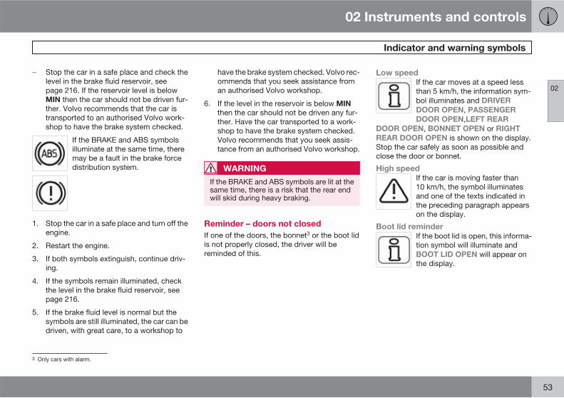
� Stop the car in a safe place and check thelevel in the brake fluid reservoir, seepage 216. If the reservoir level is belowMIN then the car should not be driven fur-ther. Volvo recommends that the car istransported to an authorised Volvo work-shop to have the brake system checked.
If the BRAKE and ABS symbolsilluminate at the same time, theremay be a fault in the brake forcedistribution system.
1. Stop the car in a safe place and turn off theengine.
2. Restart the engine.
3. If both symbols extinguish, continue driv-ing.
4. If the symbols remain illuminated, checkthe level in the brake fluid reservoir, seepage 216.
5. If the brake fluid level is normal but thesymbols are still illuminated, the car can bedriven, with great care, to a workshop to
have the brake system checked. Volvo rec-ommends that you seek assistance froman authorised Volvo workshop.
6. If the level in the reservoir is below MIN
then the car should not be driven any fur-ther. Have the car transported to a work-shop to have the brake system checked.Volvo recommends that you seek assis-tance from an authorised Volvo workshop.
WARNING
If the BRAKE and ABS symbols are lit at thesame time, there is a risk that the rear endwill skid during heavy braking.
Reminder – doors not closed
If one of the doors, the bonnet3 or the boot lidis not properly closed, the driver will bereminded of this.
Low speed
If the car moves at a speed lessthan 5 km/h, the information sym-bol illuminates and DRIVER
DOOR OPEN, PASSENGER
DOOR OPEN,LEFT REAR
DOOR OPEN, BONNET OPEN or RIGHT
REAR DOOR OPEN is shown on the display.Stop the car safely as soon as possible andclose the door or bonnet.
High speed
If the car is moving faster than10 km/h, the symbol illuminatesand one of the texts indicated inthe preceding paragraph appearson the display.
Boot lid reminder
If the boot lid is open, this informa-tion symbol will illuminate andBOOT LID OPEN will appear onthe display.
3 Only cars with alarm.
02 Instruments and controls
Information display
02
54
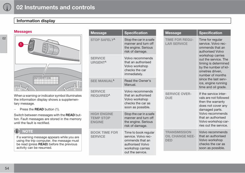
Messages
G029050
When a warning or indicator symbol illuminatesthe information display shows a supplemen-tary message.
� Press the READ button (1).
Switch between messages with the READ but-ton. Fault messages are stored in the memoryuntil the fault is rectified.
NOTE
If a warning message appears while you areusing the trip computer, the message mustbe read (press READ) before the previousactivity can be resumed.
Message Specification
STOP SAFELYA Stop the car in a safemanner and turn offthe engine. Seriousrisk of damage.
SERVICE
URGENTAVolvo recommendsthat an authorisedVolvo workshopchecks the carimmediately.
SEE MANUALA Read the Owner'sManual.
SERVICE
REQUIREDAVolvo recommendsthat an authorisedVolvo workshopchecks the car assoon as possible.
HIGH ENGINE
TEMP STOP
ENGINE
Stop the car in a safemanner and turn offthe engine. Seriousrisk of damage.
BOOK TIME FOR
SERVICE
Time to book regularservice. Volvo rec-ommends that anauthorised Volvoworkshop carriesout the service.
Message Specification
TIME FOR REGU-
LAR SERVICE
Time for regularservice. Volvo rec-ommends that anauthorised Volvoworkshop carriesout the service. Thetiming is determinedby the number of kil-ometres driven,number of monthssince the last serv-ice, engine runningtime and oil grade.
SERVICE OVER-
DUE
If the service inter-vals are not followedthen the warrantydoes not cover anydamaged parts.Volvo recommendsthat an authorisedVolvo workshop car-ries out the service.
TRANSMISSION
OIL CHANGE NEE-
DED
Volvo recommendsthat an authorisedVolvo workshopchecks the car assoon as possible.
02 Instruments and controls
Information display
02
55
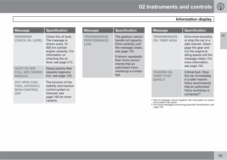
Message Specification
REMINDER
CHECK OIL LEVEL
Check the oil level.The message isshown every 10000 km (certainengine variants). Forinformation onchecking the oillevel, see page 213.
SOOT FILTER
FULL SEE OWNER
MANUAL
Diesel particle filterrequires regenera-tion, see page 140.
STC SPIN CON-
TROL OFF/DSTC
SPIN CONTROL
OFF
The function of thestability and tractioncontrol system isreduced, seepage 160 for morevariants.
Message Specification
TRANSMISSION
PERFORMANCE
LOW
The gearbox cannothandle full capacity.Drive carefully untilthe message clears,see page 155.
If shown repeatedlythen Volvo recom-mends that anauthorised Volvoworkshop is contac-ted.
Message Specification
TRANSMISSION
OIL TEMP HIGH
Drive more smoothlyor stop the car in asafe manner. Disen-gage the gear andrun the engine atidling speed until themessage clears. Formore information,see page 155.
TRANSM OIL
TEMP STOP
SAFELY
Critical fault. Stopthe car immediatelyin a safe manner.Volvo recommendsthat an authorisedVolvo workshop iscontacted.B
A Part of message, shown together with information on wherethe problem has arisen.
B For more messages concerning automatic transmission, seepage 155.
02 Instruments and controls
Electrical socket
02
56 * Option/accessory, for more information, see Introduction.
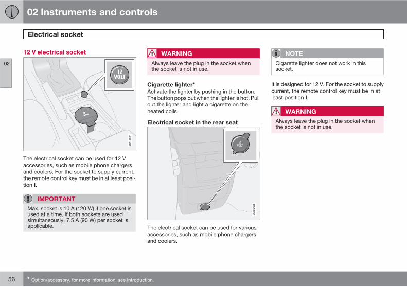
12 V electrical socket
G019621
The electrical socket can be used for 12 Vaccessories, such as mobile phone chargersand coolers. For the socket to supply current,the remote control key must be in at least posi-tion I.
IMPORTANT
Max. socket is 10 A (120 W) if one socket isused at a time. If both sockets are usedsimultaneously, 7.5 A (90 W) per socket isapplicable.
WARNING
Always leave the plug in the socket whenthe socket is not in use.
Cigarette lighter*
Activate the lighter by pushing in the button.The button pops out when the lighter is hot. Pullout the lighter and light a cigarette on theheated coils.
Electrical socket in the rear seat
G029082
The electrical socket can be used for variousaccessories, such as mobile phone chargersand coolers.
NOTE
Cigarette lighter does not work in thissocket.
It is designed for 12 V. For the socket to supplycurrent, the remote control key must be in atleast position I.
WARNING
Always leave the plug in the socket whenthe socket is not in use.
02 Instruments and controls
Lighting panel
02
��
* Option/accessory, for more information, see Introduction. 57
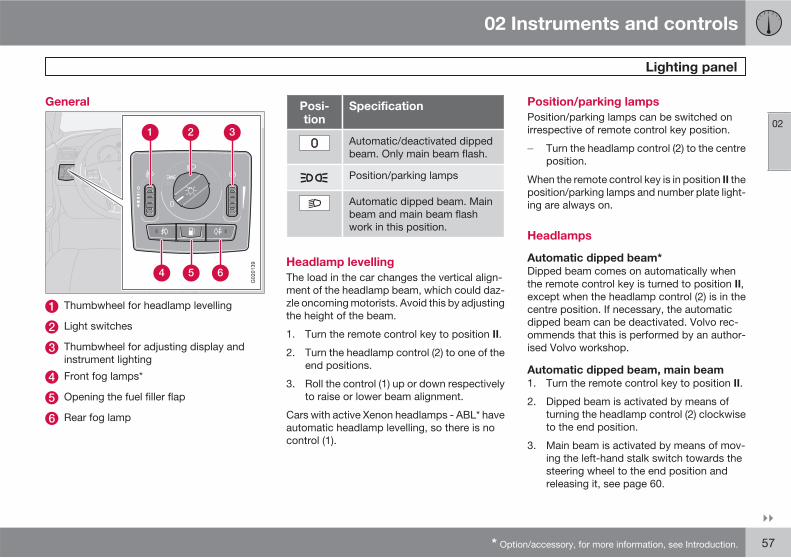
General
G020139
Thumbwheel for headlamp levelling
Light switches
Thumbwheel for adjusting display andinstrument lighting
Front fog lamps*
Opening the fuel filler flap
Rear fog lamp
Posi-tion
Specification
Automatic/deactivated dippedbeam. Only main beam flash.
Position/parking lamps
Automatic dipped beam. Mainbeam and main beam flashwork in this position.
Headlamp levelling
The load in the car changes the vertical align-ment of the headlamp beam, which could daz-zle oncoming motorists. Avoid this by adjustingthe height of the beam.
1. Turn the remote control key to position II.
2. Turn the headlamp control (2) to one of theend positions.
3. Roll the control (1) up or down respectivelyto raise or lower beam alignment.
Cars with active Xenon headlamps - ABL* haveautomatic headlamp levelling, so there is nocontrol (1).
Position/parking lamps
Position/parking lamps can be switched onirrespective of remote control key position.
� Turn the headlamp control (2) to the centreposition.
When the remote control key is in position II theposition/parking lamps and number plate light-ing are always on.
Headlamps
Automatic dipped beam*
Dipped beam comes on automatically whenthe remote control key is turned to position II,except when the headlamp control (2) is in thecentre position. If necessary, the automaticdipped beam can be deactivated. Volvo rec-ommends that this is performed by an author-ised Volvo workshop.
Automatic dipped beam, main beam
1. Turn the remote control key to position II.
2. Dipped beam is activated by means ofturning the headlamp control (2) clockwiseto the end position.
3. Main beam is activated by means of mov-ing the left-hand stalk switch towards thesteering wheel to the end position andreleasing it, see page 60.
02 Instruments and controls
Lighting panel
02
58 * Option/accessory, for more information, see Introduction.
The lamps are switched off automatically whenthe remote control key is turned to position I or0.
Instrument lighting
The instrument lighting is switched on whenthe remote control key is in position II and theheadlamp control (2) is in one of the end posi-tions. The lighting is automatically dimmedduring the day and can be controlled manuallyat night.
� Roll the control up or down (3) for brighteror dimmer lighting.
Enhanced display lighting
To facilitate reading the odometer, trip meter,clock and outside temperature gauge, theseilluminate when the car is unlocked and whenthe remote control key is removed from theignition switch. The displays extinguish whenthe car is locked.
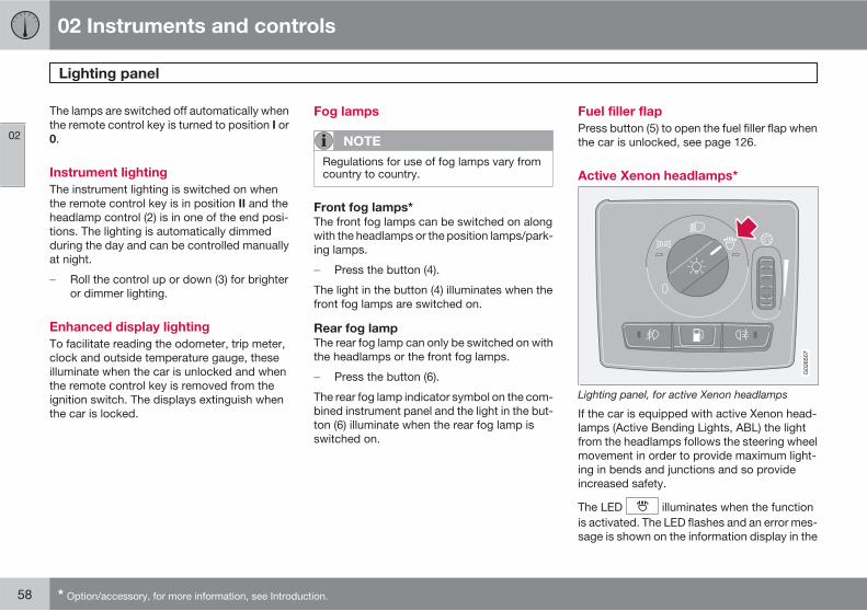
Fog lamps
NOTE
Regulations for use of fog lamps vary fromcountry to country.
Front fog lamps*
The front fog lamps can be switched on alongwith the headlamps or the position lamps/park-ing lamps.
� Press the button (4).
The light in the button (4) illuminates when thefront fog lamps are switched on.
Rear fog lamp
The rear fog lamp can only be switched on withthe headlamps or the front fog lamps.
� Press the button (6).
The rear fog lamp indicator symbol on the com-bined instrument panel and the light in the but-ton (6) illuminate when the rear fog lamp isswitched on.
Fuel filler flap
Press button (5) to open the fuel filler flap whenthe car is unlocked, see page 126.
Active Xenon headlamps*
G026507
Lighting panel, for active Xenon headlamps
If the car is equipped with active Xenon head-lamps (Active Bending Lights, ABL) the lightfrom the headlamps follows the steering wheelmovement in order to provide maximum light-ing in bends and junctions and so provideincreased safety.
The LED illuminates when the functionis activated. The LED flashes and an error mes-sage is shown on the information display in the
02 Instruments and controls
Lighting panel
02
59
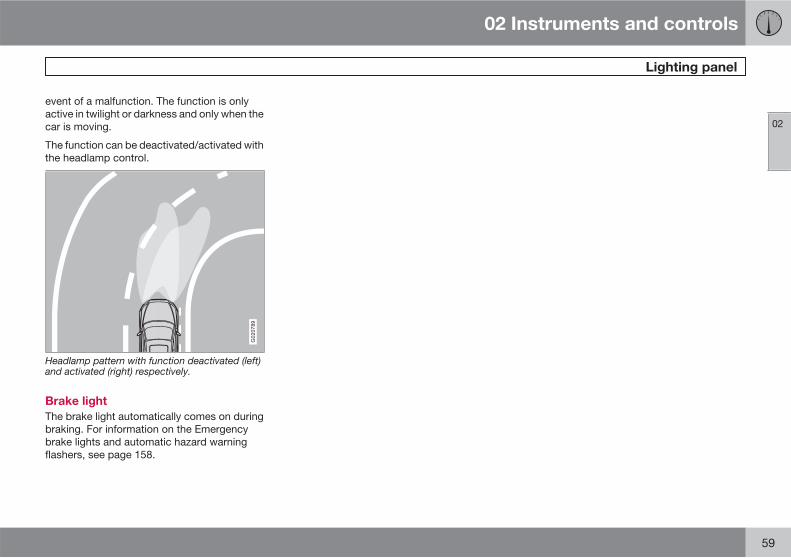
event of a malfunction. The function is onlyactive in twilight or darkness and only when thecar is moving.
The function can be deactivated/activated withthe headlamp control.
G020789
Headlamp pattern with function deactivated (left)and activated (right) respectively.
Brake light
The brake light automatically comes on duringbraking. For information on the Emergencybrake lights and automatic hazard warningflashers, see page 158.
02 Instruments and controls
Left-hand stalk switch
02
60
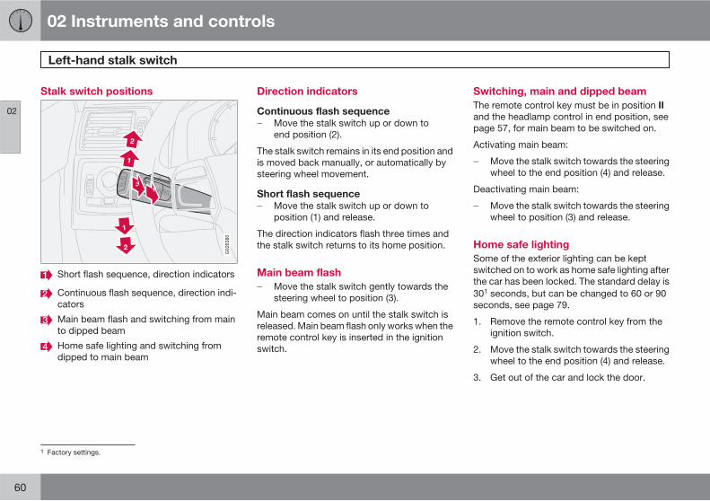
Stalk switch positions
34
1
2
1
2
G026380
Short flash sequence, direction indicators
Continuous flash sequence, direction indi-cators
Main beam flash and switching from mainto dipped beam
Home safe lighting and switching fromdipped to main beam
Direction indicators
Continuous flash sequence
� Move the stalk switch up or down toend position (2).
The stalk switch remains in its end position andis moved back manually, or automatically bysteering wheel movement.
Short flash sequence
� Move the stalk switch up or down toposition (1) and release.
The direction indicators flash three times andthe stalk switch returns to its home position.
Main beam flash
� Move the stalk switch gently towards thesteering wheel to position (3).
Main beam comes on until the stalk switch isreleased. Main beam flash only works when theremote control key is inserted in the ignitionswitch.
Switching, main and dipped beam
The remote control key must be in position IIand the headlamp control in end position, seepage 57, for main beam to be switched on.
Activating main beam:
� Move the stalk switch towards the steeringwheel to the end position (4) and release.
Deactivating main beam:
� Move the stalk switch towards the steeringwheel to position (3) and release.
Home safe lighting
Some of the exterior lighting can be keptswitched on to work as home safe lighting afterthe car has been locked. The standard delay is301 seconds, but can be changed to 60 or 90seconds, see page 79.
1. Remove the remote control key from theignition switch.
2. Move the stalk switch towards the steeringwheel to the end position (4) and release.
3. Get out of the car and lock the door.
1 Factory settings.
02 Instruments and controls
Left-hand stalk switch
02
��
* Option/accessory, for more information, see Introduction. 61
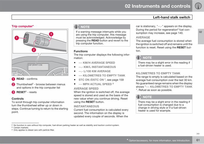
Trip computer*
G029052
READ - confirms
Thumbwheel2 - browse between menusand options in the trip computer list
RESET2 - resets
Controls
To scroll through trip computer informationturn the thumbwheel either up or down insteps. Continue turning to return to the startingpoint.
NOTE
If a warning message interrupts while youare using the trip computer, this messagemust be acknowledged. Acknowledge bypressing the READ button and revert to thetrip computer function.
Functions
The trip computer displays the following infor-mation:
• --- KM/H AVERAGE SPEED
• --.- KM/L INSTANTANEOUS
• --.- L/100 KM AVERAGE
• --- KILOMETRES TO EMPTY TANK
• STC ON /DSTC ON *, see page 159
• --- MPH ACTUAL SPEED 3
AVERAGE SPEED
When the ignition is switched off, the averagespeed is stored and used as the basis of thenew value when you continue driving. Resetusing the RESET button.
INSTANTANEOUS
Current fuel consumption is calculated everysecond. The information on the display isupdated every couple of seconds. When the
car is stationary, "--.-" appears on the display.During the period for regeneration4 fuel con-sumption may increase, see page 140.
AVERAGE
The average fuel consumption is stored whenthe ignition is switched off and remains until thefunction is reset. Reset using the RESET but-ton.
NOTE
There may be a slight error in the reading ifa fuel-driven heater is used.
KILOMETRES TO EMPTY TANK
The range to empty is calculated based on theaverage fuel consumption over the last 30 km.No guaranteed range remains when the displayshows "--- KILOMETRES TO EMPTY TANK
". Refuel as soon as possible.
NOTE
There may be a slight error in the reading iffuel consumption is changed due to achange in driving style or if a fuel-drivenheater is used for example.
2 No function in cars without trip computer, fuel-driven parking heater as well as stability and traction control system.3 Certain markets.4 Only applies to diesel cars with particle filter.
02 Instruments and controls
Left-hand stalk switch
02
62
MPH ACTUAL SPEED.3
Current speed is displayed in mph.
Resetting
1. Select --- KM/H AVERAGE SPEED or--.- L/100 KM AVERAGE
2. Reset with one press on the RESET but-ton. Press and hold the RESET button forat least five seconds to reset the averagespeed and average consumption at thesame time.
3 Certain markets.
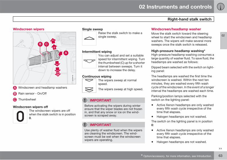
02 Instruments and controls
Right-hand stalk switch
02
��
* Option/accessory, for more information, see Introduction. 63
Windscreen wipers
0
0
A
CB
G025419
Windscreen and headlamp washers
Rain sensor - On/Off
Thumbwheel
Windscreen wipers off
The windscreen wipers are offwhen the stalk switch is in position0.
Single sweep
Raise the stalk switch to make asingle sweep.
Intermittent wiping
You can adjust and set a suitablespeed for intermittent wiping. Turnthe thumbwheel (C) up for a shorterinterval between sweeps. Turn itdown to increase the delay.
Continuous wiping
The wipers sweep at normalspeed.
The wipers sweep at high speed.
IMPORTANT
Before activating the wipers during winterensure that the wiper blades are not frozenin, and that any snow or ice on the wind-screen is scraped away.
IMPORTANT
Use plenty of washer fluid when the wipersare cleaning the windscreen. The wind-screen must be wet when the windscreenwipers are operating.
Windscreen/headlamp washer
Move the stalk switch toward the steeringwheel to start the windscreen and headlampwashers. The wipers will make several moresweeps once the stalk switch is released.
High-pressure headlamp washing*
High-pressure headlamp washing consumes alarge quantity of washer fluid. To save fluid, theheadlamps are washed as follows:
Dipped beam selected with the switch on light-ing panel:
The headlamps are washed the first time thewindscreen is washed. Within the next tenminutes, they are washed every fifth washcycle of the windscreen. In the event of a longerinterval the headlamps are washed each time.
Parking/position lamps selected with theswitch on the lighting panel:
• Active Xenon headlamps are only washedevery fifth wash cycle irrespective of thetime that elapses.
• Halogen headlamps are not washed.
The switch on the lighting panel is in position0:
• Active Xenon headlamps are only washedevery fifth wash cycle irrespective of thetime that elapses.
• Halogen headlamps are not washed.
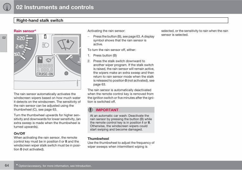
02 Instruments and controls
Right-hand stalk switch
02
64 * Option/accessory, for more information, see Introduction.
Rain sensor*
G029053
The rain sensor automatically activates thewindscreen wipers based on how much waterit detects on the windscreen. The sensitivity ofthe rain sensor can be adjusted using thethumbwheel (C), see page 63.
Turn the thumbwheel upwards for higher sen-sitivity and downwards for lower sensitivity, (anextra sweep is made when the thumbwheel isturned upwards).
On/Off
When activating the rain sensor, the remotecontrol key must be in position I or II and thewindscreen wiper stalk switch must be in posi-tion 0 (not activated).
Activating the rain sensor:
� Press the button (B), see page 63. A displaysymbol shows that the rain sensor isactive.
To turn the rain sensor off, either:
1. Press button (B)
2. Press the stalk switch downward toanother wiper program. If the stalk switchis raised, the rain sensor will remain active,the wipers make an extra sweep and thenreturn to rain sensor mode when the stalkis released to position 0 (not activated), seepage 63.
The rain sensor is automatically deactivatedwhen the remote control key is removed fromthe ignition switch or five minutes after the igni-tion is switched off.
IMPORTANT
At an automatic car wash: Deactivate therain sensor by pressing the button (B) whilethe remote control key is in position I or II.Otherwise, the windscreen wipers couldstart swiping and become damaged.
Thumbwheel
Use the thumbwheel to adjust the frequency ofwiper sweeps when intermittent wiping is
selected, or the sensitivity to rain when the rainsensor is selected.
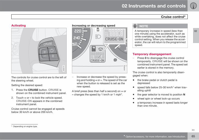
02 Instruments and controls
Cruise control*
02
��
* Option/accessory, for more information, see Introduction. 65
Activating
G020141
The controls for cruise control are to the left ofthe steering wheel.
Setting the desired speed:
1. Press the CRUISE button. CRUISE isshown on the combined instrument panel.
2. Touch + or – to lock the vehicle speed.CRUISE-ON appears in the combinedinstrument panel.
Cruise control cannot be engaged at speedsbelow 30 km/h or above 200 km/h.
Increasing or decreasing speed
G029054
� Increase or decrease the speed by press-ing and holding + or –. The speed of the carwhen the button is released is set as thenew speed.
A brief press (less than half a second) on + or– changes the speed by 1 km/h or 1 mph1.
NOTE
A temporary increase in speed (less thanone minute) using the accelerator, such aswhile overtaking, does not affect the cruisecontrol setting. When you release the accel-erator, the car will return to the programmedspeed.
Temporary disengagement
� Press 0 to disengage the cruise controltemporarily. CRUISE will be shown on thecombined instrument panel. The speed setearlier is stored in the memory.
The cruise control is also temporarily disen-gaged when:
• the brake pedal or clutch pedal isdepressed
• speed falls below 25-30 km/h1 when trav-elling uphill
• the gear selector is moved to position N
• wheel spin or wheel lock-up occurs
• a temporary increase in speed lasts longerthan one minute.
1 Depending on engine type.
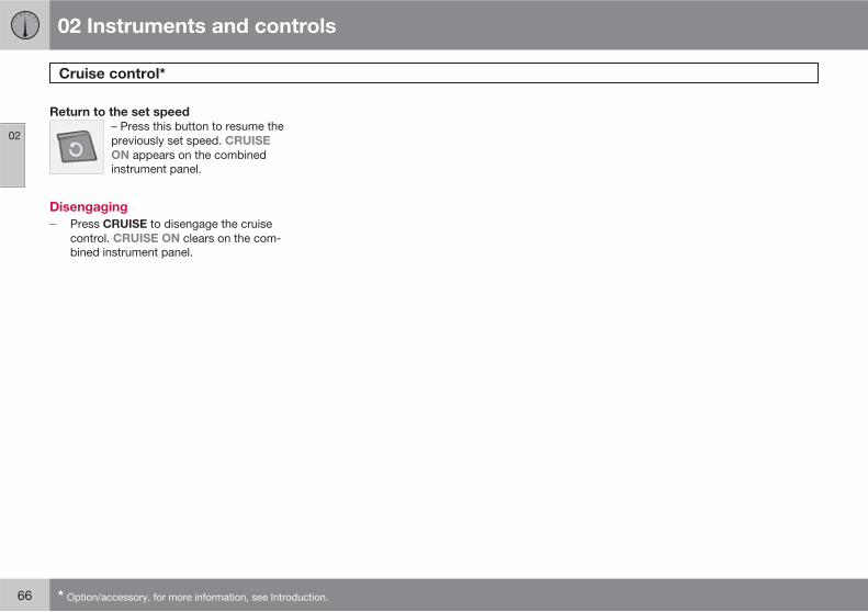
02 Instruments and controls
Cruise control*
02
66 * Option/accessory, for more information, see Introduction.
Return to the set speed
– Press this button to resume thepreviously set speed. CRUISE
ON appears on the combinedinstrument panel.
Disengaging
� Press CRUISE to disengage the cruisecontrol. CRUISE ON clears on the com-bined instrument panel.
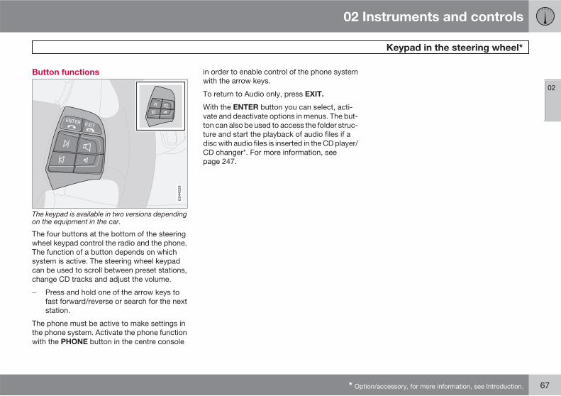
02 Instruments and controls
Keypad in the steering wheel*
02
* Option/accessory, for more information, see Introduction. 67
Button functions
The keypad is available in two versions dependingon the equipment in the car.
The four buttons at the bottom of the steeringwheel keypad control the radio and the phone.The function of a button depends on whichsystem is active. The steering wheel keypadcan be used to scroll between preset stations,change CD tracks and adjust the volume.
� Press and hold one of the arrow keys tofast forward/reverse or search for the nextstation.
The phone must be active to make settings inthe phone system. Activate the phone functionwith the PHONE button in the centre console
in order to enable control of the phone systemwith the arrow keys.
To return to Audio only, press EXIT.
With the ENTER button you can select, acti-vate and deactivate options in menus. The but-ton can also be used to access the folder struc-ture and start the playback of audio files if adisc with audio files is inserted in the CD player/CD changer*. For more information, seepage 247.
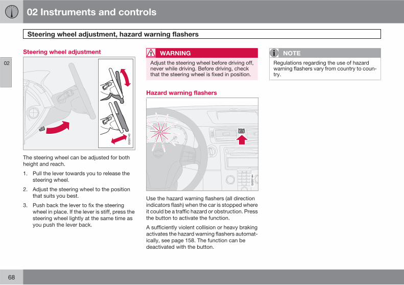
02 Instruments and controls
Steering wheel adjustment, hazard warning flashers
02
68
Steering wheel adjustment
G020143
The steering wheel can be adjusted for bothheight and reach.
1. Pull the lever towards you to release thesteering wheel.
2. Adjust the steering wheel to the positionthat suits you best.
3. Push back the lever to fix the steeringwheel in place. If the lever is stiff, press thesteering wheel lightly at the same time asyou push the lever back.
WARNING
Adjust the steering wheel before driving off,never while driving. Before driving, checkthat the steering wheel is fixed in position.
Hazard warning flashers
G020144
Use the hazard warning flashers (all directionindicators flash) when the car is stopped whereit could be a traffic hazard or obstruction. Pressthe button to activate the function.
A sufficiently violent collision or heavy brakingactivates the hazard warning flashers automat-ically, see page 158. The function can bedeactivated with the button.
NOTE
Regulations regarding the use of hazardwarning flashers vary from country to coun-try.
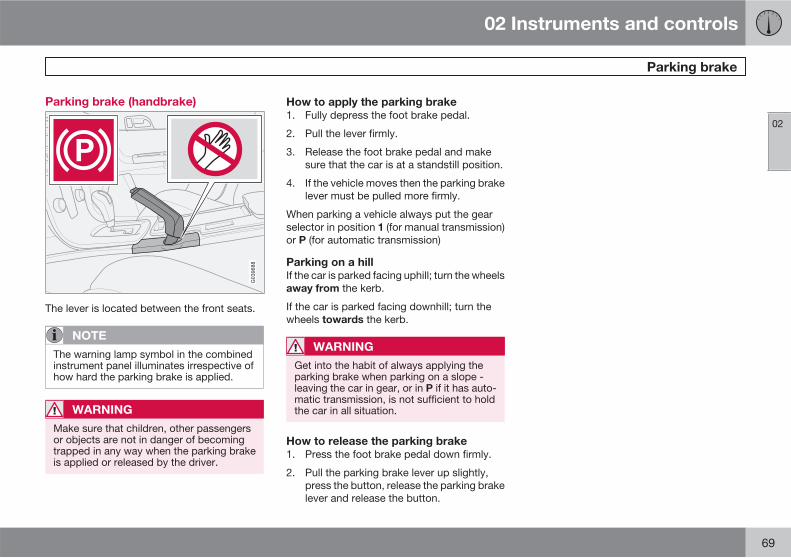
02 Instruments and controls
Parking brake
02
69
Parking brake (handbrake)
The lever is located between the front seats.
NOTE
The warning lamp symbol in the combinedinstrument panel illuminates irrespective ofhow hard the parking brake is applied.
WARNING
Make sure that children, other passengersor objects are not in danger of becomingtrapped in any way when the parking brakeis applied or released by the driver.
How to apply the parking brake
1. Fully depress the foot brake pedal.
2. Pull the lever firmly.
3. Release the foot brake pedal and makesure that the car is at a standstill position.
4. If the vehicle moves then the parking brakelever must be pulled more firmly.
When parking a vehicle always put the gearselector in position 1 (for manual transmission)or P (for automatic transmission)
Parking on a hill
If the car is parked facing uphill; turn the wheelsaway from the kerb.
If the car is parked facing downhill; turn thewheels towards the kerb.
WARNING
Get into the habit of always applying theparking brake when parking on a slope -leaving the car in gear, or in P if it has auto-matic transmission, is not sufficient to holdthe car in all situation.
How to release the parking brake
1. Press the foot brake pedal down firmly.
2. Pull the parking brake lever up slightly,press the button, release the parking brakelever and release the button.
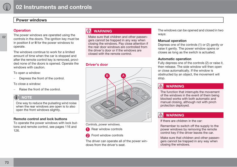
02 Instruments and controls
Power windows
02
70
Operation
The power windows are operated using thecontrols in the doors. The ignition key must bein position I or II for the power windows tooperate.
The windows continue to work for a limitedamount of time when the car is stopped andafter the remote control key is removed, provi-ded none of the doors is opened. Operate thewindows with caution.
To open a window:
� Depress the front of the control.
To close a window:
� Raise the front of the control.
NOTE
One way to reduce the pulsating wind noisewhen the rear windows are open is to alsoopen the front windows slightly.
Remote control and lock buttons
To operate the power windows with lock but-tons and remote control, see pages 116 and126.
WARNING
Make sure that children and other passen-gers cannot be trapped in any way whenclosing the windows. Pay close attention ifthe rear door windows are controlled fromthe driver's door or if the windows areclosed with the remote control.
Driver's door
Controls, power windows.
Rear window controls
Front window controls
The driver can operate all of the power win-dows from the driver's seat.
The windows can be opened and closed in twoways:
Manual operation
Depress one of the controls (1) or (2) gently orraise it gently. The power window opens orcloses as long as the switch is actuated.
Automatic operation
Fully depress one of the controls (2) or raise it,then release. The side window will then openor close automatically. If the window isobstructed by an object, the movement willstop.
WARNING
The function that interrupts the movementof the windows in the event of them beingblocked works with both automatic andmanual closing, although not with pinchprotection deployed.
WARNING
If there are children in the car:
Remember to switch off the supply to thepower windows by removing the remotecontrol key if the driver leaves the car.
Make sure that children and other passen-gers cannot be trapped in any way whenclosing the windows.
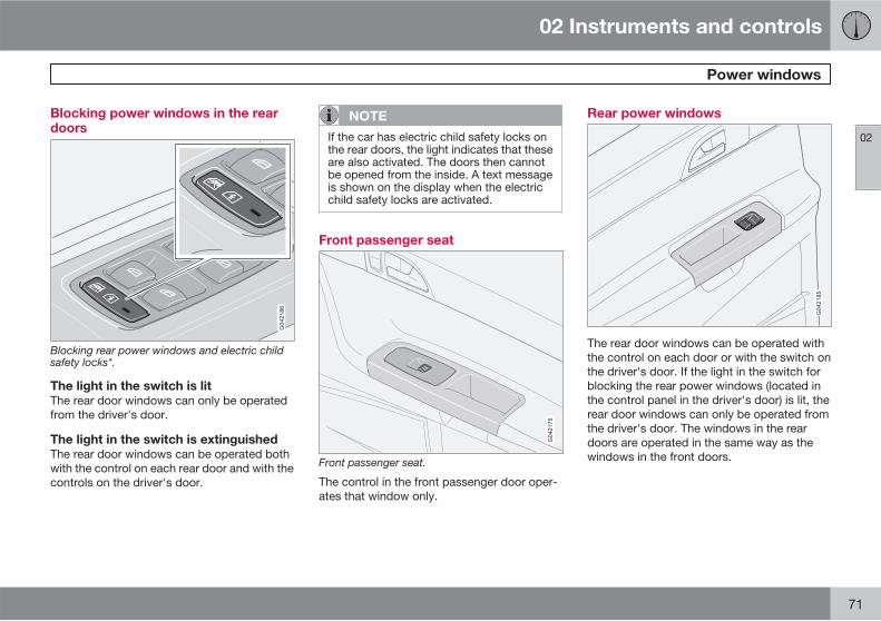
02 Instruments and controls
Power windows
02
71
Blocking power windows in the reardoors
Blocking rear power windows and electric childsafety locks*.
The light in the switch is lit
The rear door windows can only be operatedfrom the driver's door.
The light in the switch is extinguished
The rear door windows can be operated bothwith the control on each rear door and with thecontrols on the driver's door.
NOTE
If the car has electric child safety locks onthe rear doors, the light indicates that theseare also activated. The doors then cannotbe opened from the inside. A text messageis shown on the display when the electricchild safety locks are activated.
Front passenger seat
Front passenger seat.
The control in the front passenger door oper-ates that window only.
Rear power windows
The rear door windows can be operated withthe control on each door or with the switch onthe driver's door. If the light in the switch forblocking the rear power windows (located inthe control panel in the driver's door) is lit, therear door windows can only be operated fromthe driver's door. The windows in the reardoors are operated in the same way as thewindows in the front doors.
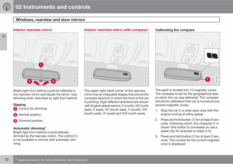
02 Instruments and controls
Windows, rearview and door mirrors
02
72 * Option/accessory, for more information, see Introduction.
Interior rearview mirror
Bright light from behind could be reflected inthe rearview mirror and dazzle the driver. Usedimming when disturbed by light from behind.
Dipping
Control for dimming
Normal position
Dimmed position.
Automatic dimming*
Bright light from behind is automaticallydimmed by the rearview mirror. The control (1)is not available in mirrors with automatic dim-ming.
Interior rearview mirror with compass*
G031043
The upper right-hand corner of the rearviewmirror has an integrated display that shows thecompass direction in which the front of the caris pointing. Eight different directions are shownwith English abbreviations: N (north), NE (northeast), E (east), SE (south east), S (south), SW
(south west), W (west) and NW (north west).
Calibrating the compass
G031045
The earth is divided into 15 magnetic zones.The compass is set for the geographical areato which the car was delivered. The compassshould be calibrated if the car is moved acrossseveral magnetic zones.
1. Stop the car in a wide open area with theengine running at idling speed.
2. Press and hold button (1) for at least 6 sec-onds. Following which, the character C isshown (the button is concealed so use apaper clip for example to press it in).
3. Press and hold button (1) for at least 3 sec-onds. The number for the current magneticzone is displayed.
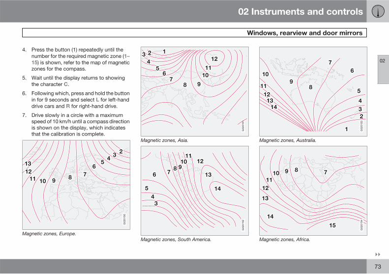
02 Instruments and controls
Windows, rearview and door mirrors
02
��
73
4. Press the button (1) repeatedly until thenumber for the required magnetic zone (1–
15) is shown, refer to the map of magneticzones for the compass.
5. Wait until the display returns to showingthe character C.
6. Following which, press and hold the buttonin for 9 seconds and select L for left-handdrive cars and R for right-hand drive.
7. Drive slowly in a circle with a maximumspeed of 10 km/h until a compass directionis shown on the display, which indicatesthat the calibration is complete.
G020150
Magnetic zones, Europe.
G020151
Magnetic zones, Asia.
G020152
Magnetic zones, South America.
G020153
Magnetic zones, Australia.
G020154
Magnetic zones, Africa.
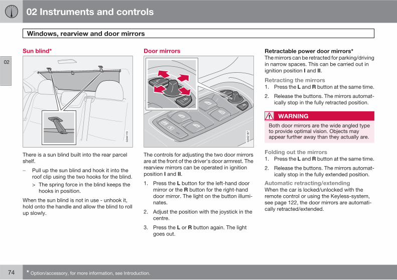
02 Instruments and controls
Windows, rearview and door mirrors
02
74 * Option/accessory, for more information, see Introduction.
Sun blind*
There is a sun blind built into the rear parcelshelf.
� Pull up the sun blind and hook it into theroof clip using the two hooks for the blind.> The spring force in the blind keeps the
hooks in position.
When the sun blind is not in use - unhook it,hold onto the handle and allow the blind to rollup slowly.
Door mirrors
The controls for adjusting the two door mirrorsare at the front of the driver's door armrest. Therearview mirrors can be operated in ignitionposition I and II.
1. Press the L button for the left-hand doormirror or the R button for the right-handdoor mirror. The light on the button illumi-nates.
2. Adjust the position with the joystick in thecentre.
3. Press the L or R button again. The lightgoes out.
Retractable power door mirrors*
The mirrors can be retracted for parking/drivingin narrow spaces. This can be carried out inignition position I and II.
Retracting the mirrors
1. Press the L and R button at the same time.
2. Release the buttons. The mirrors automat-ically stop in the fully retracted position.
WARNING
Both door mirrors are the wide angled typeto provide optimal vision. Objects mayappear further away than they actually are.
Folding out the mirrors
1. Press the L and R button at the same time.
2. Release the buttons. The mirrors automat-ically stop in the fully extended position.
Automatic retracting/extending
When the car is locked/unlocked with theremote control or using the Keyless-system,see page 122, the door mirrors are automati-cally retracted/extended.
02 Instruments and controls
Windows, rearview and door mirrors
02
* Option/accessory, for more information, see Introduction. 75
NOTE
The door mirrors will not be extended auto-matically during unlocking if they wereretracted using the controls in the door.
If the car is locked with the remote controland is then started, the door mirrors will stillbe extended.
The function can be activated/deactivatedunder Car settings… Mirror fold on
locking, see page 79 for a description of themenu system.
Resetting to neutral
Mirrors that have been moved out of positionby an external force must be reset to the neutralposition for electric retracting and extending towork.
1. Use the L and R buttons to retract the mir-rors.
2. Extend the mirrors again with the L and Rbutton. The mirrors are now reset to theneutral.
Home safe and approach lighting
The light* on the door mirrors illuminates whenthe approach lighting or home safe lighting isactivated.
Blind Spot Information System, BLIS*
BLIS is an information system that under cer-tain conditions can help to draw the driver'sattention to vehicles moving in the same direc-tion in the so-called "blind spot", seepage 163.
Water and dirt-repellent coating*
The front side windows are treatedwith a coating which improves the view
in poor weather conditions. For information onmaintenance, see page 201.
IMPORTANT
Do not use a metal ice scraper to remove icefrom the windows. The water and dirt-repel-lent coating could be damaged.
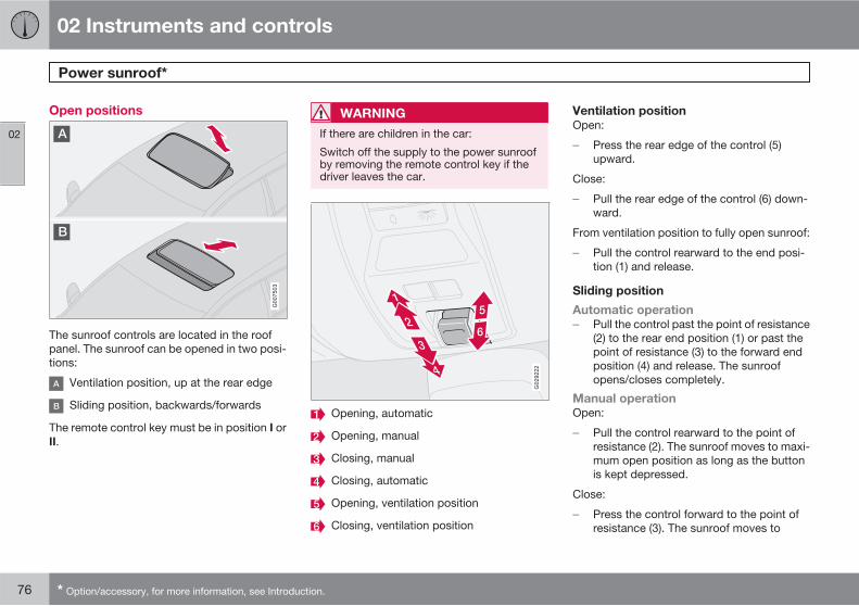
02 Instruments and controls
Power sunroof*
02
76 * Option/accessory, for more information, see Introduction.
Open positions
G007503
The sunroof controls are located in the roofpanel. The sunroof can be opened in two posi-tions:
Ventilation position, up at the rear edge
Sliding position, backwards/forwards
The remote control key must be in position I orII.
WARNING
If there are children in the car:
Switch off the supply to the power sunroofby removing the remote control key if thedriver leaves the car.
G029222
Opening, automatic
Opening, manual
Closing, manual
Closing, automatic
Opening, ventilation position
Closing, ventilation position
Ventilation position
Open:
� Press the rear edge of the control (5)upward.
Close:
� Pull the rear edge of the control (6) down-ward.
From ventilation position to fully open sunroof:
� Pull the control rearward to the end posi-tion (1) and release.
Sliding position
Automatic operation
� Pull the control past the point of resistance(2) to the rear end position (1) or past thepoint of resistance (3) to the forward endposition (4) and release. The sunroofopens/closes completely.
Manual operation
Open:
� Pull the control rearward to the point ofresistance (2). The sunroof moves to maxi-mum open position as long as the buttonis kept depressed.
Close:
� Press the control forward to the point ofresistance (3). The sunroof moves to
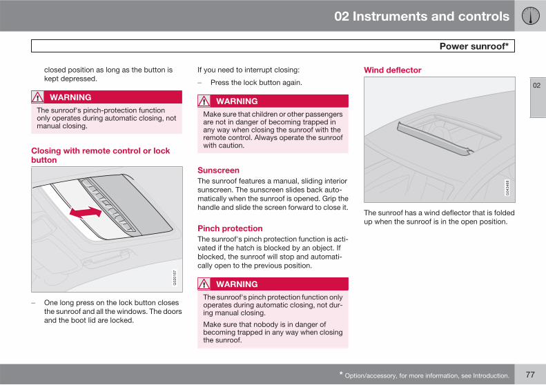
02 Instruments and controls
Power sunroof*
02
* Option/accessory, for more information, see Introduction. 77
closed position as long as the button iskept depressed.
WARNING
The sunroof's pinch-protection functiononly operates during automatic closing, notmanual closing.
Closing with remote control or lockbutton
G020157
� One long press on the lock button closesthe sunroof and all the windows. The doorsand the boot lid are locked.
If you need to interrupt closing:
� Press the lock button again.
WARNING
Make sure that children or other passengersare not in danger of becoming trapped inany way when closing the sunroof with theremote control. Always operate the sunroofwith caution.
Sunscreen
The sunroof features a manual, sliding interiorsunscreen. The sunscreen slides back auto-matically when the sunroof is opened. Grip thehandle and slide the screen forward to close it.
Pinch protection
The sunroof's pinch protection function is acti-vated if the hatch is blocked by an object. Ifblocked, the sunroof will stop and automati-cally open to the previous position.
WARNING
The sunroof's pinch protection function onlyoperates during automatic closing, not dur-ing manual closing.
Make sure that nobody is in danger ofbecoming trapped in any way when closingthe sunroof.
Wind deflector
The sunroof has a wind deflector that is foldedup when the sunroof is in the open position.
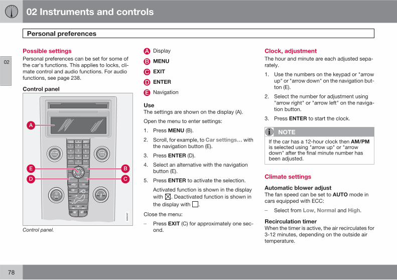
02 Instruments and controls
Personal preferences
02
78
Possible settings
Personal preferences can be set for some ofthe car's functions. This applies to locks, cli-mate control and audio functions. For audiofunctions, see page 238.
Control panel
A
D
B
C
E
G02
6307
Control panel.
Display
MENU
EXIT
ENTER
Navigation
Use
The settings are shown on the display (A).
Open the menu to enter settings:
1. Press MENU (B).
2. Scroll, for example, to Car settings… withthe navigation button (E).
3. Press ENTER (D).
4. Select an alternative with the navigationbutton (E).
5. Press ENTER to activate the selection.
Activated function is shown in the displaywith . Deactivated function is shown inthe display with .
Close the menu:
� Press EXIT (C) for approximately one sec-ond.
Clock, adjustment
The hour and minute are each adjusted sepa-rately.
1. Use the numbers on the keypad or "arrowup" or "arrow down" on the navigation but-ton (E).
2. Select the number for adjustment using"arrow right" or "arrow left" on the naviga-tion button.
3. Press ENTER to start the clock.
NOTE
If the car has a 12-hour clock then AM/PMis selected using "arrow up" or "arrowdown" after the final minute number hasbeen adjusted.
Climate settings
Automatic blower adjust
The fan speed can be set to AUTO mode incars equipped with ECC:
� Select from Low, Normal and High.
Recirculation timer
When the timer is active, the air recirculates for3-12 minutes, depending on the outside airtemperature.
02 Instruments and controls
Personal preferences
02
��
* Option/accessory, for more information, see Introduction. 79
� Select On/Off depending on whether or notyou wish the recirculation timer to beactive.
Reset all
Resets the climate function options to the fac-tory settings.
Car settings
Retract mirrors when locking*
When the car is locked/unlocked with theremote control the door mirrors can be retrac-ted/extended automatically. The On/Off optionis available.
Reduced guard*
The deadlocks function can be temporarilydeactivated and the alarm level reduced ifsomeone wishes to remain in the car and thedoors have to be locked from the outside. TheActivate once and Ask on exit options areavailable, see pages 127 and 131.
Unlock confirm. light
The hazard warning flashers can provide feed-back when the car is unlocked with the remotecontrol. The On/Off option is available.
Lock confirm. light
The hazard warning flashers can provide feed-back when the car is locked with the remotecontrol. The On/Off option is available.
Doors – auto lock
When the speed of the car exceeds 7 km/h thedoors and boot lid can be locked automatically.The On/Off option is available. Pulling the doorhandle twice unlocks and opens the doorsfrom the inside.
Doors unlock
There are two alternatives for unlocking:
• All doors – one press of the remote controlunlocks all doors and the boot lid.
• Driver door, then all – one press of theremote control unlocks the driver's door. Asecond press then unlocks the passengerdoor and the boot lid.
Keyless entry*
• All doors - all doors are unlocked simul-taneously.
• Doors on same side – front and reardoors on the same side are unlockedsimultaneously.
• Both front doors – both front doors areunlocked simultaneously.
• Either front door – any door or the bootlid can be unlocked separately.
Simultaneous closing/opening of all
windows
This function can be selected for the lock but-ton on the remote control and the front doors'
central locking button, as well as the outsidedoor handle button on cars with the keylesssystem:
• Auto. close all windows - all windowsand the sunroof are closed simultaneouslywith one long press on the lock button.
This function can be selected for the unlockbutton on the remote control and the frontdoors' central locking button:
• Auto. open all windows – all windows areopened simultaneously with one longpress on the unlock button.
Approach lighting
Select the time the car's lights should remainon when the approach lighting button ispressed. The following alternatives are availa-ble:
• 30 seconds
• 60 seconds
• 90 seconds
Home safe lighting
Select the time the car's lights should remainon when the left-hand stalk switch is pulledback after the remote control key has beenremoved. The following alternatives are avail-able:
02 Instruments and controls
Personal preferences
02
80
• 30 seconds
• 60 seconds
• 90 seconds
Information
• VIN number… - (Vehicle IdentificationNumber) is the car's unique identity num-ber.
• Number of keys… - The number of keysregistered for the car is shown.
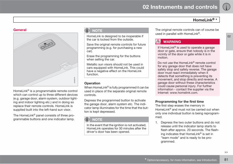
02 Instruments and controls
HomeLink *
02
��
* Option/accessory, for more information, see Introduction. 81
General
G030070
HomeLink is a programmable remote controlwhich can control up to three different devices(e.g. garage door, alarm system, outdoor light-ing and indoor lighting etc.) and in doing soreplace their remote controls. HomeLink issupplied built into the left-hand sun visor.
The HomeLink panel consists of three pro-grammable buttons and one indicator lamp.
NOTE
HomeLink is designed to be inoperable ifthe car is locked from the outside.
Save the original remote controls for futureprogramming (e.g. for purchasing a newcar).
Erase the programming for the buttonswhen selling the car.
Metallic sun visors should not be used incars equipped with HomeLink. This couldhave a negative effect on the HomeLinkfunction.
Operation
When HomeLink is fully programmed it can beused in place of the separate original remotecontrols.
Depress the programmed button to activatethe garage door, alarm system etc. The indi-cator lamp illuminates for the time that the but-ton is kept depressed.
NOTE
In the event that the ignition is not activated,HomeLink operates for 30 minutes after thedriver's door has been opened.
The original remote controls can of course beused in parallel with HomeLink .
WARNING
If HomeLink is used to operate a garagedoor or gate, ensure that nobody is in thevicinity of the door or gate while it is inmotion.
Do not use the HomeLink remote controlfor any garage door that does not havesafety stop and safety reverse. The garagedoor must react immediately when itdetects that something is preventing itsmovement, and stop directly and reverse. Agarage door without these characteristicscould cause personal injury. For furtherinformation - contact the supplier via theInternet: www.homelink.com.
Programming for the first time
The first step erases the memory inHomeLink and must not be carried out whenonly one individual button is being reprogram-med.
1. Depress the two outer buttons and do notrelease until the indicator lamp starts toflash after approx. 20 seconds. The flash-ing indicates that HomeLink is set in"learn mode" and is ready to be pro-grammed.
02 Instruments and controls
HomeLink *
02
82 * Option/accessory, for more information, see Introduction.
2. Position the original remote control5-30 cm from HomeLink . Monitor the indi-cator lamp.
The particular distance that is requiredbetween the original remote control andHomeLink depends on the programmingof the device in question. Perhaps severalattempts will be required at different dis-tances. Maintain each position for approx.15 seconds before trying a new one.
3. Depress the button for the original remotecontrol and the button to be programmedon HomeLink simultaneously. Do notrelease the buttons until the indicator lamphas changed over from slow to rapid flash-ing. The rapid flashing indicates successfulprogramming.
4. Test the programming by depressing theprogrammed button on HomeLink andwatching the indicator lamp:
• Constant glow: The indicator lamp illu-minates with a constant glow when thebutton is kept depressed, this indicatesthat the programming is complete. Thegarage door, gate or similar should nowbe activated when the programmedHomeLink button is depressed.
• Glow not constant: The indicator lampflashes quickly for approx. 2 secondsand then changes over to a constantglow for approx. 3 seconds. This proc-ess is repeated for approx. 20 secondsand indicates that the device has a "roll-ing code". The garage door, gate or sim-ilar is not activated when the pro-grammed HomeLink button isdepressed. Continue the programmingin accordance with the following.
5. Locate the "programming button1" on thereceiver for the garage door for example,normally located close to the antenna'sbracket on the receiver. If you have diffi-culty in finding the button - consult thesupplier's manual, or contact the suppliervia the Internet: www.homelink.com.
6. Depress and release the "programmingbutton". The button flashes forapprox. 30 seconds and the next step mustbe carried out within this period.
7. Depress the programmed button onHomeLink , while the "programming but-ton" is still flashing, keep it depressed forapprox. 3 seconds and then release.Repeat the press/hold/release sequenceup to 3 times to conclude the program-ming.
Programming individual buttons
To reprogram an individual button, proceed inaccordance with the following:
1. Depress the required button onHomeLink and do not release until step 3has been completed.
2. When the indicator lamp on HomeLinkstarts to flash, after approx. 20 seconds,position the original remote control5-30 cm from HomeLink . Monitor the indi-cator lamp.
The particular distance that is requiredbetween the original remote control andHomeLink depends on the programming ofthe device in question. Perhaps severalattempts will be required at different dis-tances. Maintain each position for approx.15 seconds before trying a new one.
3. Depress the button on the original remotecontrol. The indicator lamp will start toflash. When the flashing has changed overfrom a slow to a rapid flashing - releaseboth buttons. The rapid flashing indicatessuccessful programming.
4. Test the programming by depressing theprogrammed button on HomeLink andwatching the indicator lamp:
1 Button designation and colour vary depending on manufacturer.
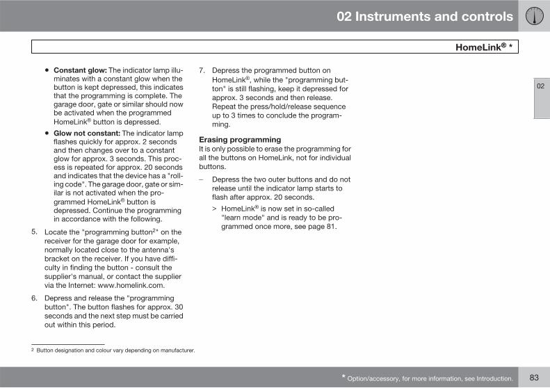
02 Instruments and controls
HomeLink *
02
* Option/accessory, for more information, see Introduction. 83
• Constant glow: The indicator lamp illu-minates with a constant glow when thebutton is kept depressed, this indicatesthat the programming is complete. Thegarage door, gate or similar should nowbe activated when the programmedHomeLink button is depressed.
• Glow not constant: The indicator lampflashes quickly for approx. 2 secondsand then changes over to a constantglow for approx. 3 seconds. This proc-ess is repeated for approx. 20 secondsand indicates that the device has a "roll-ing code". The garage door, gate or sim-ilar is not activated when the pro-grammed HomeLink button isdepressed. Continue the programmingin accordance with the following.
5. Locate the "programming button2" on thereceiver for the garage door for example,normally located close to the antenna'sbracket on the receiver. If you have diffi-culty in finding the button - consult thesupplier's manual, or contact the suppliervia the Internet: www.homelink.com.
6. Depress and release the "programmingbutton". The button flashes for approx. 30seconds and the next step must be carriedout within this period.
7. Depress the programmed button onHomeLink , while the "programming but-ton" is still flashing, keep it depressed forapprox. 3 seconds and then release.Repeat the press/hold/release sequenceup to 3 times to conclude the program-ming.
Erasing programming
It is only possible to erase the programming forall the buttons on HomeLink, not for individualbuttons.
� Depress the two outer buttons and do notrelease until the indicator lamp starts toflash after approx. 20 seconds.> HomeLink is now set in so-called
"learn mode" and is ready to be pro-grammed once more, see page 81.
2 Button designation and colour vary depending on manufacturer.
84 * Option/accessory, for more information, see Introduction.
General information on climate control................................................... 86Manual climate control, AC..................................................................... 88Electronic climate control, ECC*............................................................. 91Air distribution......................................................................................... 94Fuel-driven engine block heaterand passenger compartment heater*..................................................... 95Fuel-driven auxiliary heater* (diesel)....................................................... 98
CLIMATE CONTROL
03 Climate control
General information on climate control
03
86
Air conditioning
The climate control system cools or heats aswell as dehumidifies the air in the passengercompartment. The car is equipped with eithermanual (AC) or electronic climate control (ECC,Electronic Climate Control).
NOTE
The air conditioning system can beswitched off, but to ensure the best possibleair in the passenger compartment and pre-vent the windows from misting, it shouldalways be on.
Misting windows
Remove misting on the insides of the windowsby first using the defroster function.
To reduce the risk of misting, clean the win-dows with a normal window cleaning agent.
Ice and snow
Remove ice and snow from the climate controlair intake (the grille between the bonnet and thewindscreen).
Fault tracing and repair
Volvo recommends that you only entrust faulttracing and repair of the climate control systemto an authorised Volvo workshop.
Refrigerant
The air conditioning system contains R134arefrigerant. This refrigerant contains no chlo-rine, which means that it is harmless to theozone layer. The system must only be chargedwith R134a refrigerant, see also page 278.Volvo recommends that an authorised Volvoworkshop carries out this work.
Passenger compartment filter
All air entering the car's passenger compart-ment is only cleaned with one filter. This mustbe replaced at regular intervals. Follow theVolvo Service Programme for the recom-mended replacement intervals. If the car isused in a severely contaminated environment,it may be necessary to replace the filter moreoften.
NOTE
There are different types of passenger com-partment filter. Make sure that the correctfilter is fitted.
Display
There is a display above the climate controlpanel. This displays climate control settings.
Personal preferences
You can set preferences for two climate controlfunctions:
• Fan speed in AUTO mode (applies only tocars with ECC).
• Recirculation timer for passenger com-partment air.
For information about these settings, seepage 78.
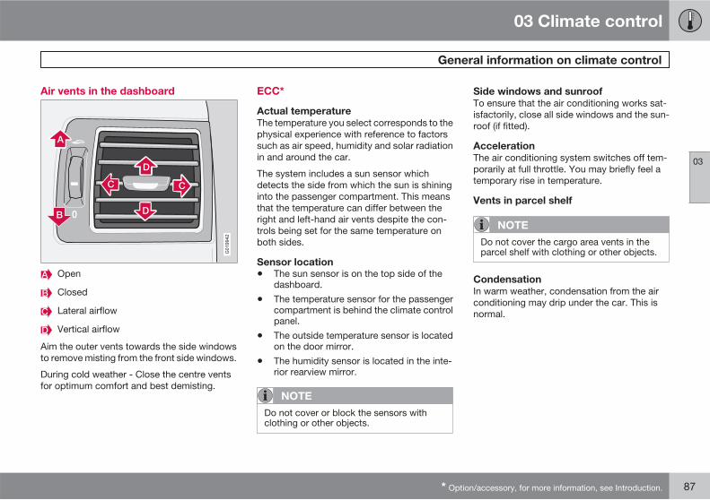
03 Climate control
General information on climate control
03
* Option/accessory, for more information, see Introduction. 87
Air vents in the dashboard
G019942
Open
Closed
Lateral airflow
Vertical airflow
Aim the outer vents towards the side windowsto remove misting from the front side windows.
During cold weather - Close the centre ventsfor optimum comfort and best demisting.
ECC*
Actual temperature
The temperature you select corresponds to thephysical experience with reference to factorssuch as air speed, humidity and solar radiationin and around the car.
The system includes a sun sensor whichdetects the side from which the sun is shininginto the passenger compartment. This meansthat the temperature can differ between theright and left-hand air vents despite the con-trols being set for the same temperature onboth sides.
Sensor location
• The sun sensor is on the top side of thedashboard.
• The temperature sensor for the passengercompartment is behind the climate controlpanel.
• The outside temperature sensor is locatedon the door mirror.
• The humidity sensor is located in the inte-rior rearview mirror.
NOTE
Do not cover or block the sensors withclothing or other objects.
Side windows and sunroof
To ensure that the air conditioning works sat-isfactorily, close all side windows and the sun-roof (if fitted).
Acceleration
The air conditioning system switches off tem-porarily at full throttle. You may briefly feel atemporary rise in temperature.
Vents in parcel shelf
NOTE
Do not cover the cargo area vents in theparcel shelf with clothing or other objects.
Condensation
In warm weather, condensation from the airconditioning may drip under the car. This isnormal.
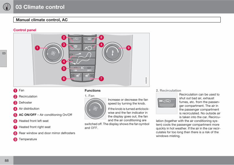
03 Climate control
Manual climate control, AC
03
88
Control panel
7
1 9
2
3
5
6
8
4
4
G026308
Fan
Recirculation
Defroster
Air distribution
AC ON/OFF – Air conditioning On/Off
Heated front left seat
Heated front right seat
Rear window and door mirror defrosters
Temperature
Functions
1. Fan
Increase or decrease the fanspeed by turning the knob.
If the knob is turned anticlock-wise and the fan indicator inthe display goes out, the fanand the air conditioning are
switched off. The display shows the fan symboland OFF.
2. Recirculation
Recirculation can be used toshut out bad air, exhaustfumes, etc. from the passen-ger compartment. The air inthe passenger compartmentis recirculated. No outside airis taken into the car. Recircu-
lation (together with the air conditioning sys-tem) cools the passenger compartment morequickly in hot weather. If the air in the car recir-culates for too long then there is a risk of thewindows misting.
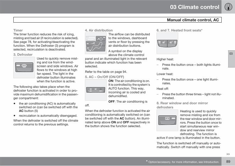
03 Climate control
Manual climate control, AC
03
��
* Option/accessory, for more information, see Introduction. 89
Timer
The timer function reduces the risk of icing,misting and bad air (if recirculation is selected).See page 78, for activating/deactivating thefunction. When the Defroster (3) program isselected, recirculation is deactivated.
3. Defroster
Used to quickly remove mist-ing and ice from the wind-screen and side windows. Airflows to the windows at highfan speed. The light in thedefroster button illuminateswhen the function is active.
The following also takes place when thedefroster function is activated in order to pro-vide maximum dehumidification in the passen-ger compartment:
• the air conditioning (AC) is automaticallyswitched on (can be switched off with theAC button (5)
• recirculation is automatically disengaged.
When the defroster is switched off the climatecontrol returns to the previous settings.
4. Air distribution
The airflow can be distributedto the windows, dashboardvents or floor by pressing theair distribution buttons.
A symbol on the displayabove the climate control
panel and an illuminated light in the relevantbutton indicate which function has beenselected.
Refer to the table on page 94.
5. AC – On/Off (ON/OFF)
ON: The air conditioning is on.It is controlled by the system'sAUTO function. This way,incoming air is cooled anddehumidified.
OFF: The air conditioning isoff.
When the defroster function is activated the airconditioning is automatically switched on (canbe switched off with the AC button). An illumi-nated lamp above ON and OFF respectively inthe button shows the function selected.
6. and 7. Heated front seats*
Higher heat:
� Press the button once – both lights illumi-nate.
Lower heat:
� Press the button once – one light illumi-nates.
Heat off:
� Press the button three times – light not illu-minated.
8. Rear window and door mirror
defrosters
Heating is used to quicklyremove misting and ice fromthe rear window and door mir-rors. Press the button once tostart simultaneous rear win-dow and rearview mirrordefrosting. The function is
active if one lamp is illuminated in the button.
The function is switched off manually or auto-matically. Switch off manually with one press
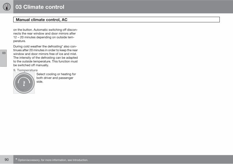
03 Climate control
Manual climate control, AC
03
90 * Option/accessory, for more information, see Introduction.
on the button. Automatic switching off discon-nects the rear window and door mirrors after12 – 20 minutes depending on outside tem-perature.
During cold weather the defrosting* also con-tinues after 20 minutes in order to keep the rearwindow and door mirrors free of ice and mist.The intensity of the defrosting can be adaptedto the outside temperature. This function mustbe switched off manually.
9. Temperature
Select cooling or heating forboth driver and passengerside.
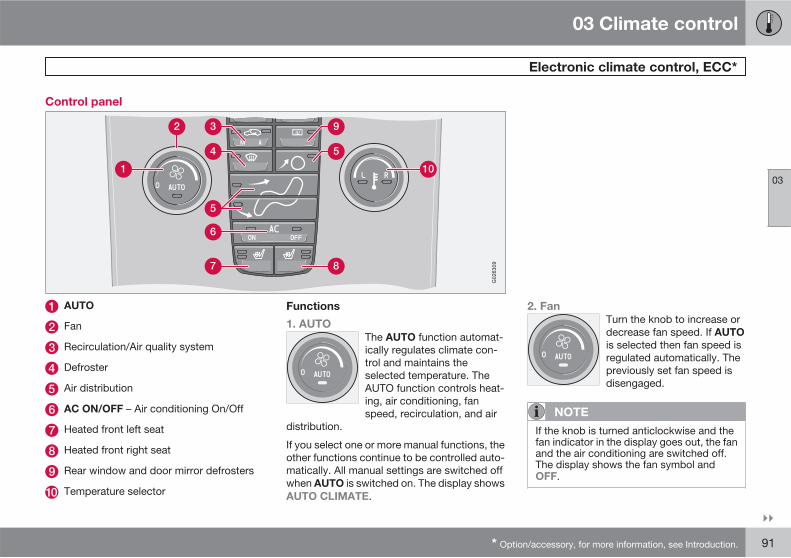
03 Climate control
Electronic climate control, ECC*
03
��
* Option/accessory, for more information, see Introduction. 91
Control panel
6
7
3
4
9
5
1 10
8
5
2
G026309
AUTO
Fan
Recirculation/Air quality system
Defroster
Air distribution
AC ON/OFF – Air conditioning On/Off
Heated front left seat
Heated front right seat
Rear window and door mirror defrosters
Temperature selector
Functions
1. AUTO
The AUTO function automat-ically regulates climate con-trol and maintains theselected temperature. TheAUTO function controls heat-ing, air conditioning, fanspeed, recirculation, and air
distribution.
If you select one or more manual functions, theother functions continue to be controlled auto-matically. All manual settings are switched offwhen AUTO is switched on. The display showsAUTO CLIMATE.
2. Fan
Turn the knob to increase ordecrease fan speed. If AUTO
is selected then fan speed isregulated automatically. Thepreviously set fan speed isdisengaged.
NOTE
If the knob is turned anticlockwise and thefan indicator in the display goes out, the fanand the air conditioning are switched off.The display shows the fan symbol andOFF.
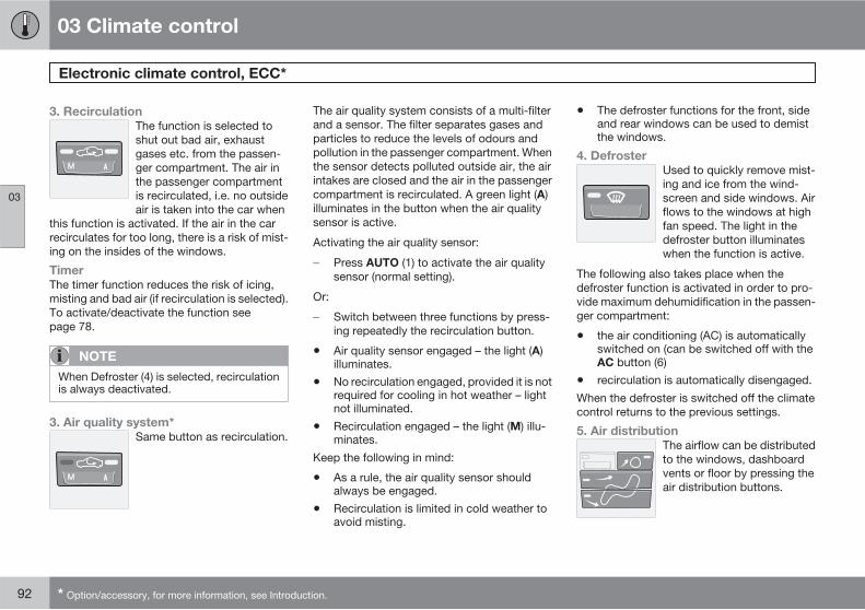
03 Climate control
Electronic climate control, ECC*
03
92 * Option/accessory, for more information, see Introduction.
3. Recirculation
The function is selected toshut out bad air, exhaustgases etc. from the passen-ger compartment. The air inthe passenger compartmentis recirculated, i.e. no outsideair is taken into the car when
this function is activated. If the air in the carrecirculates for too long, there is a risk of mist-ing on the insides of the windows.
Timer
The timer function reduces the risk of icing,misting and bad air (if recirculation is selected).To activate/deactivate the function seepage 78.
NOTE
When Defroster (4) is selected, recirculationis always deactivated.
3. Air quality system*
Same button as recirculation.
The air quality system consists of a multi-filterand a sensor. The filter separates gases andparticles to reduce the levels of odours andpollution in the passenger compartment. Whenthe sensor detects polluted outside air, the airintakes are closed and the air in the passengercompartment is recirculated. A green light (A)illuminates in the button when the air qualitysensor is active.
Activating the air quality sensor:
� Press AUTO (1) to activate the air qualitysensor (normal setting).
Or:
� Switch between three functions by press-ing repeatedly the recirculation button.
• Air quality sensor engaged – the light (A)illuminates.
• No recirculation engaged, provided it is notrequired for cooling in hot weather – lightnot illuminated.
• Recirculation engaged – the light (M) illu-minates.
Keep the following in mind:
• As a rule, the air quality sensor shouldalways be engaged.
• Recirculation is limited in cold weather toavoid misting.
• The defroster functions for the front, sideand rear windows can be used to demistthe windows.
4. Defroster
Used to quickly remove mist-ing and ice from the wind-screen and side windows. Airflows to the windows at highfan speed. The light in thedefroster button illuminateswhen the function is active.
The following also takes place when thedefroster function is activated in order to pro-vide maximum dehumidification in the passen-ger compartment:
• the air conditioning (AC) is automaticallyswitched on (can be switched off with theAC button (6)
• recirculation is automatically disengaged.
When the defroster is switched off the climatecontrol returns to the previous settings.
5. Air distribution
The airflow can be distributedto the windows, dashboardvents or floor by pressing theair distribution buttons.
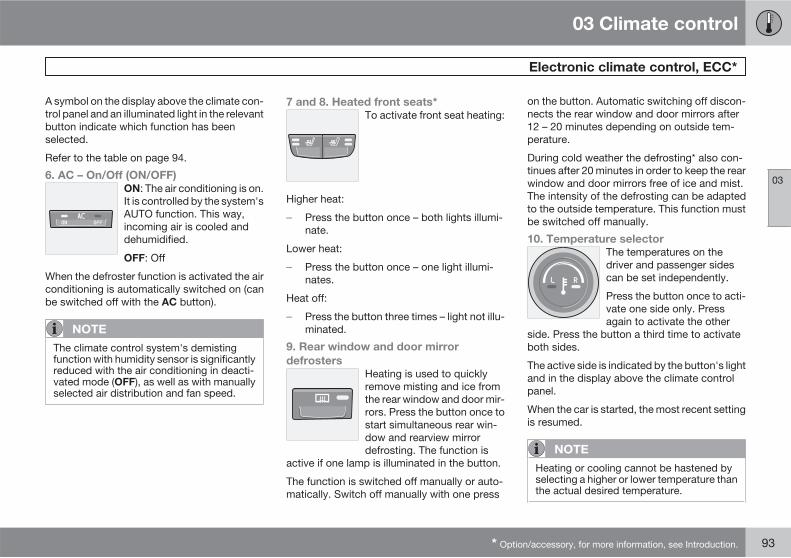
03 Climate control
Electronic climate control, ECC*
03
* Option/accessory, for more information, see Introduction. 93
A symbol on the display above the climate con-trol panel and an illuminated light in the relevantbutton indicate which function has beenselected.
Refer to the table on page 94.
6. AC – On/Off (ON/OFF)
ON: The air conditioning is on.It is controlled by the system'sAUTO function. This way,incoming air is cooled anddehumidified.
OFF: Off
When the defroster function is activated the airconditioning is automatically switched on (canbe switched off with the AC button).
NOTE
The climate control system's demistingfunction with humidity sensor is significantlyreduced with the air conditioning in deacti-vated mode (OFF), as well as with manuallyselected air distribution and fan speed.
7 and 8. Heated front seats*
To activate front seat heating:
Higher heat:
� Press the button once – both lights illumi-nate.
Lower heat:
� Press the button once – one light illumi-nates.
Heat off:
� Press the button three times – light not illu-minated.
9. Rear window and door mirror
defrosters
Heating is used to quicklyremove misting and ice fromthe rear window and door mir-rors. Press the button once tostart simultaneous rear win-dow and rearview mirrordefrosting. The function is
active if one lamp is illuminated in the button.
The function is switched off manually or auto-matically. Switch off manually with one press
on the button. Automatic switching off discon-nects the rear window and door mirrors after12 – 20 minutes depending on outside tem-perature.
During cold weather the defrosting* also con-tinues after 20 minutes in order to keep the rearwindow and door mirrors free of ice and mist.The intensity of the defrosting can be adaptedto the outside temperature. This function mustbe switched off manually.
10. Temperature selector
The temperatures on thedriver and passenger sidescan be set independently.
Press the button once to acti-vate one side only. Pressagain to activate the other
side. Press the button a third time to activateboth sides.
The active side is indicated by the button's lightand in the display above the climate controlpanel.
When the car is started, the most recent settingis resumed.
NOTE
Heating or cooling cannot be hastened byselecting a higher or lower temperature thanthe actual desired temperature.
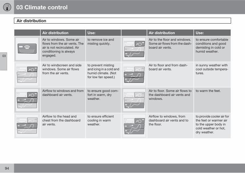
03 Climate control
Air distribution
03
94
Air distribution Use: Air distribution Use:
Air to windows. Some airflows from the air vents. Theair is not recirculated. Airconditioning is alwaysengaged.
to remove ice andmisting quickly.
Air to the floor and windows.Some air flows from the dash-board air vents.
to ensure comfortableconditions and gooddemisting in cold orhumid weather.
Air to windscreen and sidewindows. Some air flowsfrom the air vents.
to prevent mistingand icing in a cold andhumid climate. (Notfor low fan speed.)
Air to floor and from dash-board air vents.
in sunny weather withcool outside tempera-tures.
Airflow to windows and fromdashboard air vents.
to ensure good com-fort in warm, dryweather.
Air to floor. Some air flows tothe dashboard air vents andwindows.
to warm the feet.
Airflow to the head andchest from the dashboardair vents.
to ensure efficientcooling in warmweather.
Airflow to windows, fromdashboard air vents and tothe floor.
to provide cooler air forthe feet or warmer airto the upper body incold weather or hot,dry weather.
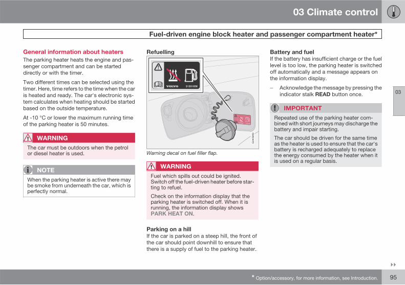
03 Climate control
Fuel-driven engine block heater and passenger compartment heater*
03
��
* Option/accessory, for more information, see Introduction. 95
General information about heaters
The parking heater heats the engine and pas-senger compartment and can be starteddirectly or with the timer.
Two different times can be selected using thetimer. Here, time refers to the time when the caris heated and ready. The car's electronic sys-tem calculates when heating should be startedbased on the outside temperature.
At -10 °C or lower the maximum running timeof the parking heater is 50 minutes.
WARNING
The car must be outdoors when the petrolor diesel heater is used.
NOTE
When the parking heater is active there maybe smoke from underneath the car, which isperfectly normal.
Refuelling
Warning decal on fuel filler flap.
WARNING
Fuel which spills out could be ignited.Switch off the fuel-driven heater before star-ting to refuel.
Check on the information display that theparking heater is switched off. When it isrunning, the information display showsPARK HEAT ON.
Parking on a hill
If the car is parked on a steep hill, the front ofthe car should point downhill to ensure thatthere is a supply of fuel to the parking heater.
Battery and fuel
If the battery has insufficient charge or the fuellevel is too low, the parking heater is switchedoff automatically and a message appears onthe information display.
� Acknowledge the message by pressing theindicator stalk READ button once.
IMPORTANT
Repeated use of the parking heater com-bined with short journeys may discharge thebattery and impair starting.
The car should be driven for the same timeas the heater is used to ensure that the car'sbattery is recharged adequately to replacethe energy consumed by the heater when itis used on a regular basis.
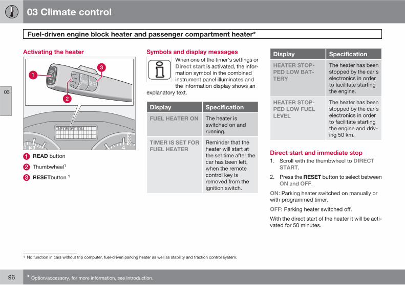
03 Climate control
Fuel-driven engine block heater and passenger compartment heater*
03
96 * Option/accessory, for more information, see Introduction.
Activating the heater
G029052
READ button
Thumbwheel1
RESETbutton 1
Symbols and display messages
When one of the timer's settings orDirect start is activated, the infor-mation symbol in the combinedinstrument panel illuminates andthe information display shows an
explanatory text.
Display Specification
FUEL HEATER ON The heater isswitched on andrunning.
TIMER IS SET FOR
FUEL HEATER
Reminder that theheater will start atthe set time after thecar has been left,when the remotecontrol key isremoved from theignition switch.
Display Specification
HEATER STOP-
PED LOW BAT-
TERY
The heater has beenstopped by the car'selectronics in orderto facilitate startingthe engine.
HEATER STOP-
PED LOW FUEL
LEVEL
The heater has beenstopped by the car'selectronics in orderto facilitate startingthe engine and driv-ing 50 km.
Direct start and immediate stop
1. Scroll with the thumbwheel to DIRECT
START.
2. Press the RESET button to select betweenON and OFF.
ON: Parking heater switched on manually orwith programmed timer.
OFF: Parking heater switched off.
With the direct start of the heater it will be acti-vated for 50 minutes.
1 No function in cars without trip computer, fuel-driven parking heater as well as stability and traction control system.
03 Climate control
Fuel-driven engine block heater and passenger compartment heater*
03
* Option/accessory, for more information, see Introduction. 97
Heating of the passenger compartment willbegin as soon as the engine coolant hasreached the correct temperature.
NOTE
The car can be started and driven while theparking heater is running.
Setting the timer
The time when the car shall be used and heatedis specified with the timer.
Select between TIMER 1 and TIMER 2.
1. Scroll with the thumbwheel to PARK
HEAT TIMER 1.
2. Briefly press the RESET button so that thehours setting starts to flash.
3. Select the required hour using the thumb-wheel.
4. Briefly press RESET to move to the flash-ing minutes setting.
5. Select the required minute using thethumbwheel.
6. Briefly press RESET to confirm the setting.
7. Press RESET to activate the timer.
After setting TIMER 1 a second start time canbe programmed with TIMER 2 by scrolling withthe thumbwheel.
Set the alternative time in the same way asTIMER 1.
Deactivating a timer-started heater
A timer-started heater can be switched offmanually before the set time has elapsed. Pro-ceed as follows:
1. Press the READ button.
2. Use the thumbwheel to scroll to the textPARK HEAT TIMER 1 or PARK HEAT
TIMER 2.
The text ON flashes on the display.
3. Press RESET.
The text OFF is shown with a constantglow and the heater is switched OFF.
A timer-started heater can be switched off inaccordance with the instructions in the section"Direct start and immediate stop".
Clock/timer
The heater's time is connected to the car'sclock.
NOTE
All timer programming will be cleared if thecar's clock is reset.
03 Climate control
Fuel-driven auxiliary heater* (diesel)
03
98 * Option/accessory, for more information, see Introduction.
Auxiliary heater (diesel)
In diesel-engined cars the auxiliary heater maybe required for achieving the correct tempera-ture in the engine and passenger compartmentduring cold weather.
The heater starts automatically when extraheat is required when the engine is running.
The heater is switched off automatically whenthe correct temperature is reached or when theengine is switched off.
NOTE
The auxiliary heater cannot be switched onor off manually but is only controlled by thecar's electronics.
When the auxiliary heater is active there maybe smoke from underneath the car, which isperfectly normal.
03 Climate control
03
99
100
Front seats ........................................................................................... 102Interior lighting...................................................................................... 104Storage spaces in the passenger compartment .................................. 106Rear seat............................................................................................... 110Cargo area............................................................................................ 112
INTERIOR
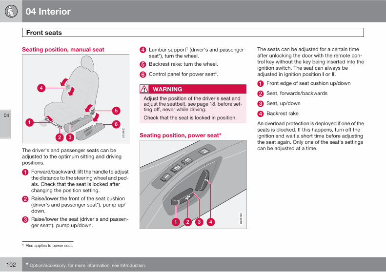
04 Interior
Front seats
04
102 * Option/accessory, for more information, see Introduction.
Seating position, manual seat
The driver's and passenger seats can beadjusted to the optimum sitting and drivingpositions.
Forward/backward: lift the handle to adjustthe distance to the steering wheel and ped-als. Check that the seat is locked afterchanging the position setting.
Raise/lower the front of the seat cushion(driver's and passenger seat*), pump up/down.
Raise/lower the seat (driver's and passen-ger seat*), pump up/down.
Lumbar support1 (driver's and passengerseat*), turn the wheel.
Backrest rake: turn the wheel.
Control panel for power seat*.
WARNING
Adjust the position of the driver's seat andadjust the seatbelt, see page 18, before set-ting off, never while driving.
Check that the seat is locked in position.
Seating position, power seat*
G020199
The seats can be adjusted for a certain timeafter unlocking the door with the remote con-trol key without the key being inserted into theignition switch. The seat can always beadjusted in ignition position I or II.
Front edge of seat cushion up/down
Seat, forwards/backwards
Seat, up/down
Backrest rake
An overload protection is deployed if one of theseats is blocked. If this happens, turn off theignition and wait a short time before adjustingthe seat again. Only one of the seat's settingscan be adjusted at a time.
1 Also applies to power seat.
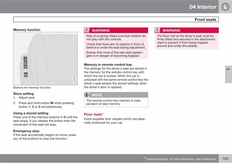
04 Interior
Front seats
04
* Option/accessory, for more information, see Introduction. 103
Memory function
G020200
Buttons for memory function.
Store setting
1. Adjust seat.
2. Press and hold button M while pressingbutton 1, 2 or 3 simultaneously.
Using a stored setting
Press one of the memory buttons 1–3 until theseat stops. If you release the button then themovement of the seat will stop.
Emergency stop
If the seat accidentally begins to move, pressany of the buttons to stop the function.
WARNING
Risk of crushing. Make sure that children donot play with the controls.
Check that there are no objects in front of,behind or under the seat during adjustment.
Ensure that none of the rear seat passen-gers is in danger of becoming trapped.
Memory in remote control key
The settings for the driver's seat are stored inthe memory for the remote control key withwhich the car is locked. When the car isunlocked with the same remote control key thedriver's seat adopts the stored settings whenthe driver's door is opened.
NOTE
The remote control key memory is inde-pendent of seat memory.
Floor mats*
Volvo supplies floor carpets which are espe-cially produced for your car.
WARNING
The floor mat at the driver's seat must befirmly fitted and secured in the attachmentclips to prevent it from being trappedaround and under the pedals.
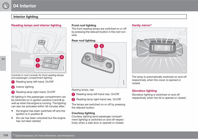
04 Interior
Interior lighting
04
104 * Option/accessory, for more information, see Introduction.
Reading lamps and interior lighting
G020201
Controls in roof console for front reading lampsand passenger compartment lighting.
Reading lamp left-hand, On/Off
Interior lighting
Reading lamp right-hand, On/Off
All lighting in the passenger compartment canbe switched on in ignition position I and II aswell as when the engine is running. The lightingcan also be activated within 30 minutes after:
• the engine has been switched off and theignition is in position 0
• the car has been unlocked but the enginehas not been started.
Front roof lighting
The front reading lamps are switched on or offby pressing the relevant button in the roof con-sole.
Rear roof lighting
G030855
Reading lamps, rear.
Reading lamp left-hand rear, On/Off
Reading lamp right-hand rear, On/Off
The lamps are switched on or off by pressingthe relevant button.
Courtesy lighting
Courtesy lighting (and passenger compart-ment lighting) is switched on and off respec-tively when a side door is opened or closed.
Vanity mirror*
G020210
The lamp is automatically switched on and offrespectively when the cover is opened orclosed.
Glovebox lighting
Glovebox lighting is switched on and offrespectively when the lid is opened or closed.
04 Interior
Interior lighting
04
105
Automatic lighting
Using the switch (2), see page 104, three posi-tions can be selected for the lighting the pas-senger compartment:
• Off – right-hand side (marked with 0)depressed, automatic lighting switchedoff.
• Neutral position – automatic lighting acti-vated. The dimmer function is active.
• On – left-hand side depressed, passengercompartment lighting on.
Neutral position
When the switch (2) is in neutral position pas-senger compartment lighting is switched onand off automatically in accordance with thebelow.
The passenger compartment lighting isswitched on and remains on for 30 seconds if:
• the car is unlocked with the remote controlkey or key blade.
• the engine is stopped and the remote con-trol key is turned to position 0.
Passenger compartment lighting is switchedoff when:
• the engine is started
• the car is locked with the key or remotecontrol key.
Passenger compartment lighting comes onand remains on for 5 minutes if one of the doorsis open.
If any lighting is switched on manually and thecar is locked then it will be switched off auto-matically after 5 minutes.
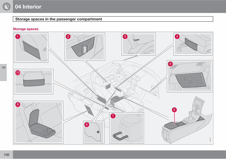
04 Interior
Storage spaces in the passenger compartment
04
106
Storage spaces
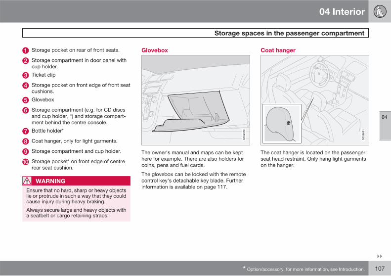
04 Interior
Storage spaces in the passenger compartment
04
��
* Option/accessory, for more information, see Introduction. 107
Storage pocket on rear of front seats.
Storage compartment in door panel withcup holder.
Ticket clip
Storage pocket on front edge of front seatcushions.
Glovebox
Storage compartment (e.g. for CD discsand cup holder, *) and storage compart-ment behind the centre console.
Bottle holder*
Coat hanger, only for light garments.
Storage compartment and cup holder.
Storage pocket* on front edge of centrerear seat cushion.
WARNING
Ensure that no hard, sharp or heavy objectslie or protrude in such a way that they couldcause injury during heavy braking.
Always secure large and heavy objects witha seatbelt or cargo retaining straps.
Glovebox
G024208
The owner's manual and maps can be kepthere for example. There are also holders forcoins, pens and fuel cards.
The glovebox can be locked with the remotecontrol key's detachable key blade. Furtherinformation is available on page 117.
Coat hanger
The coat hanger is located on the passengerseat head restraint. Only hang light garmentson the hanger.
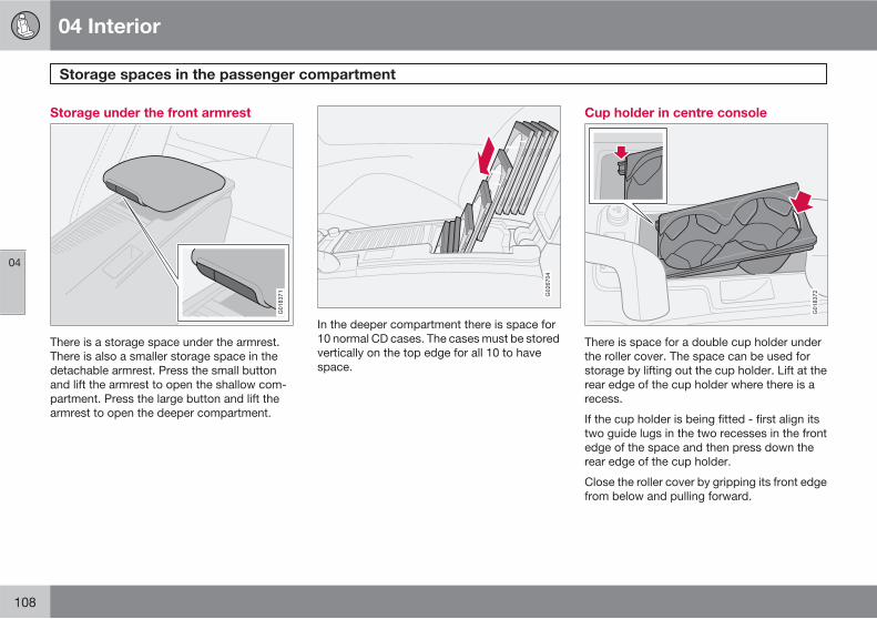
04 Interior
Storage spaces in the passenger compartment
04
108
Storage under the front armrest
G018371
There is a storage space under the armrest.There is also a smaller storage space in thedetachable armrest. Press the small buttonand lift the armrest to open the shallow com-partment. Press the large button and lift thearmrest to open the deeper compartment.
G026704
In the deeper compartment there is space for10 normal CD cases. The cases must be storedvertically on the top edge for all 10 to havespace.
Cup holder in centre console
G018372
There is space for a double cup holder underthe roller cover. The space can be used forstorage by lifting out the cup holder. Lift at therear edge of the cup holder where there is arecess.
If the cup holder is being fitted - first align itstwo guide lugs in the two recesses in the frontedge of the space and then press down therear edge of the cup holder.
Close the roller cover by gripping its front edgefrom below and pulling forward.
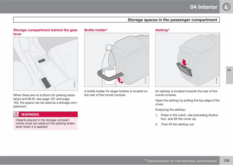
04 Interior
Storage spaces in the passenger compartment
04
* Option/accessory, for more information, see Introduction. 109
Storage compartment behind the gearlever
When there are no buttons for parking assis-tance and BLIS, see page 161 and page163, the space can be used as a storage com-partment.
WARNING
Objects placed in the storage compart-ments must not obstruct the parking brakelever when it is applied.
Bottle holder*
G017441
A bottle holder for larger bottles is located onthe rear of the tunnel console.
Ashtray*
G019622
An ashtray is located towards the rear of thetunnel console.
Open the ashtray by pulling the top edge of thecover.
Emptying the ashtray:
1. Press in the catch, see preceding illustra-tion, and tilt the cover up.
2. Then lift the ashtray out.
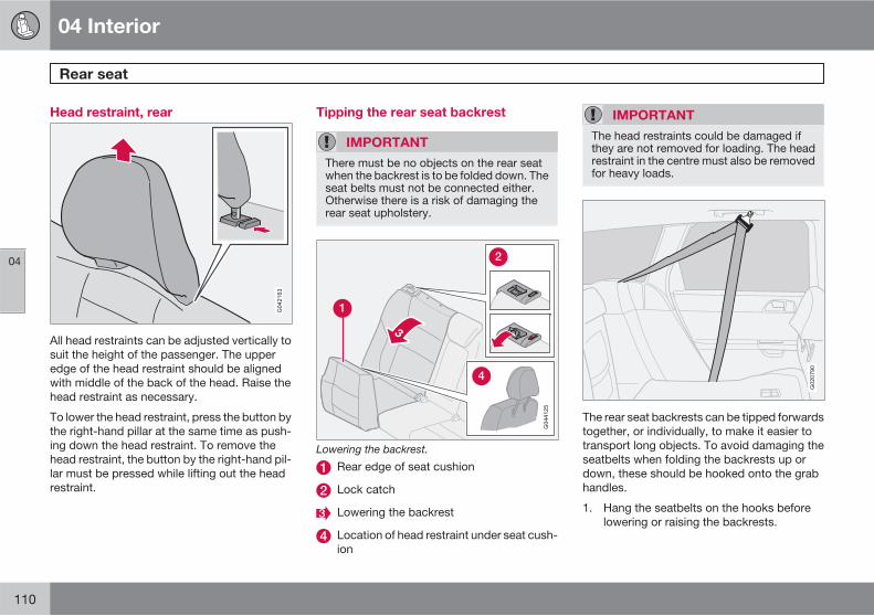
04 Interior
Rear seat
04
110
Head restraint, rear
All head restraints can be adjusted vertically tosuit the height of the passenger. The upperedge of the head restraint should be alignedwith middle of the back of the head. Raise thehead restraint as necessary.
To lower the head restraint, press the button bythe right-hand pillar at the same time as push-ing down the head restraint. To remove thehead restraint, the button by the right-hand pil-lar must be pressed while lifting out the headrestraint.
Tipping the rear seat backrest
IMPORTANT
There must be no objects on the rear seatwhen the backrest is to be folded down. Theseat belts must not be connected either.Otherwise there is a risk of damaging therear seat upholstery.
Lowering the backrest.
Rear edge of seat cushion
Lock catch
Lowering the backrest
Location of head restraint under seat cush-ion
IMPORTANT
The head restraints could be damaged ifthey are not removed for loading. The headrestraint in the centre must also be removedfor heavy loads.
G020790
The rear seat backrests can be tipped forwardstogether, or individually, to make it easier totransport long objects. To avoid damaging theseatbelts when folding the backrests up ordown, these should be hooked onto the grabhandles.
1. Hang the seatbelts on the hooks beforelowering or raising the backrests.
04 Interior
Rear seat
04
111
2. Lift the rear edge of the seat cushion (1) tofold the seat cushions forward.
3. Pull the lock (2) catch up and forward torelease the backrest. A red indicator on thelock catch shows that the backrest is nolonger locked in place.
4. Fold the backrests (3) forward halfway andremove the head restraints on the outsideseats. The centre seat's head restraintmust be removed for a fully level floor.
5. Place the head restraints in the plasticsleeves on the undersides (4) of the raisedseat cushions.
NOTE
When the backrest has been raised, the redindicator should no longer be showing. If itis still showing then the backrest is notlocked in place.
WARNING
Remember to take down the seatbelts onceyou have raised the backrest.
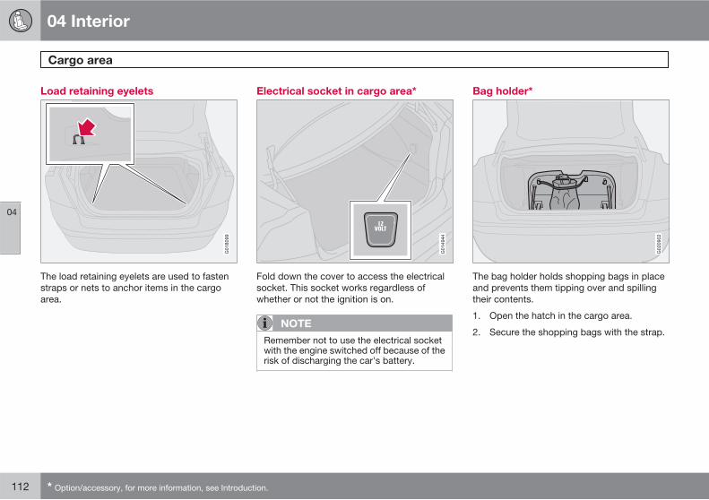
04 Interior
Cargo area
04
112 * Option/accessory, for more information, see Introduction.
Load retaining eyelets
G018099
The load retaining eyelets are used to fastenstraps or nets to anchor items in the cargoarea.
Electrical socket in cargo area*
G014944
Fold down the cover to access the electricalsocket. This socket works regardless ofwhether or not the ignition is on.
NOTE
Remember not to use the electrical socketwith the engine switched off because of therisk of discharging the car's battery.
Bag holder*
G020902
The bag holder holds shopping bags in placeand prevents them tipping over and spillingtheir contents.
1. Open the hatch in the cargo area.
2. Secure the shopping bags with the strap.
04 Interior
04
113
114 * Option/accessory, for more information, see Introduction.
Remote control key with key blade....................................................... 116Active locks........................................................................................... 119Privacy locking* .................................................................................... 120Keyless drive*........................................................................................ 122Battery in remote control key................................................................ 125Locking and unlocking ......................................................................... 126Child safety locks.................................................................................. 129Alarm* ................................................................................................... 130
LOCKS AND ALARM
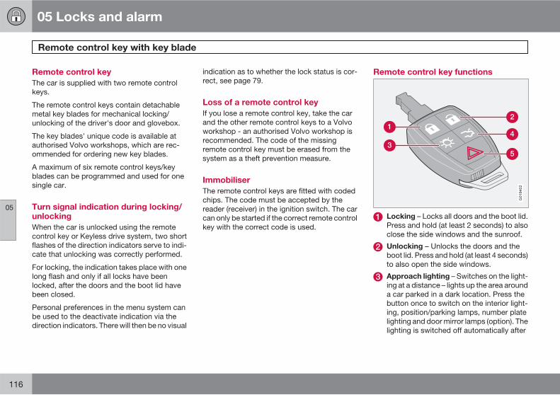
05 Locks and alarm
Remote control key with key blade
05
116
Remote control key
The car is supplied with two remote controlkeys.
The remote control keys contain detachablemetal key blades for mechanical locking/unlocking of the driver's door and glovebox.
The key blades' unique code is available atauthorised Volvo workshops, which are rec-ommended for ordering new key blades.
A maximum of six remote control keys/keyblades can be programmed and used for onesingle car.
Turn signal indication during locking/unlocking
When the car is unlocked using the remotecontrol key or Keyless drive system, two shortflashes of the direction indicators serve to indi-cate that unlocking was correctly performed.
For locking, the indication takes place with onelong flash and only if all locks have beenlocked, after the doors and the boot lid havebeen closed.
Personal preferences in the menu system canbe used to the deactivate indication via thedirection indicators. There will then be no visual
indication as to whether the lock status is cor-rect, see page 79.
Loss of a remote control key
If you lose a remote control key, take the carand the other remote control keys to a Volvoworkshop - an authorised Volvo workshop isrecommended. The code of the missingremote control key must be erased from thesystem as a theft prevention measure.
Immobiliser
The remote control keys are fitted with codedchips. The code must be accepted by thereader (receiver) in the ignition switch. The carcan only be started if the correct remote controlkey with the correct code is used.
Remote control key functions
G019402
Locking – Locks all doors and the boot lid.Press and hold (at least 2 seconds) to alsoclose the side windows and the sunroof.
Unlocking – Unlocks the doors and theboot lid. Press and hold (at least 4 seconds)to also open the side windows.
Approach lighting – Switches on the light-ing at a distance – lights up the area arounda car parked in a dark location. Press thebutton once to switch on the interior light-ing, position/parking lamps, number platelighting and door mirror lamps (option). Thelighting is switched off automatically after
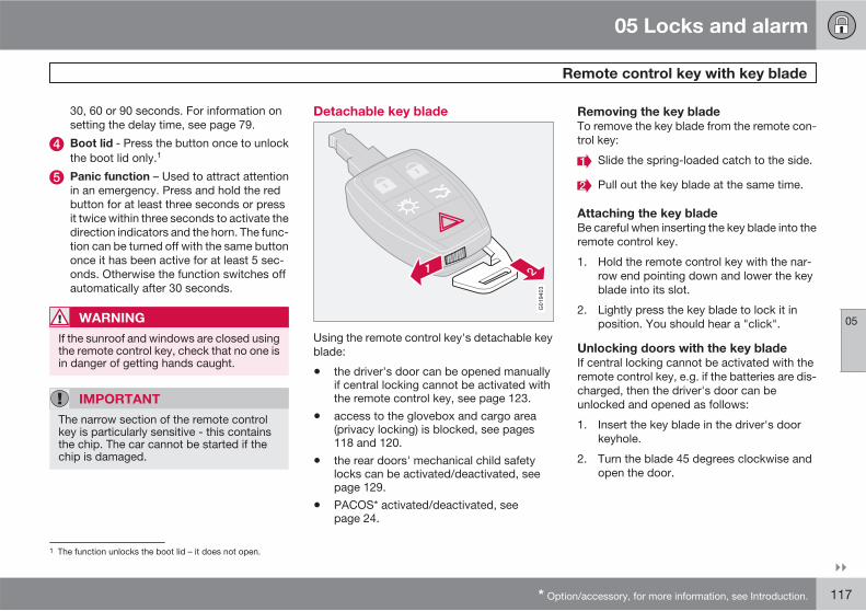
05 Locks and alarm
Remote control key with key blade
05
��
* Option/accessory, for more information, see Introduction. 117
30, 60 or 90 seconds. For information onsetting the delay time, see page 79.
Boot lid - Press the button once to unlockthe boot lid only.1
Panic function – Used to attract attentionin an emergency. Press and hold the redbutton for at least three seconds or pressit twice within three seconds to activate thedirection indicators and the horn. The func-tion can be turned off with the same buttononce it has been active for at least 5 sec-onds. Otherwise the function switches offautomatically after 30 seconds.
WARNING
If the sunroof and windows are closed usingthe remote control key, check that no one isin danger of getting hands caught.
IMPORTANT
The narrow section of the remote controlkey is particularly sensitive - this containsthe chip. The car cannot be started if thechip is damaged.
Detachable key blade
G019403
Using the remote control key's detachable keyblade:
• the driver's door can be opened manuallyif central locking cannot be activated withthe remote control key, see page 123.
• access to the glovebox and cargo area(privacy locking) is blocked, see pages118 and 120.
• the rear doors' mechanical child safetylocks can be activated/deactivated, seepage 129.
• PACOS* activated/deactivated, seepage 24.
Removing the key blade
To remove the key blade from the remote con-trol key:
Slide the spring-loaded catch to the side.
Pull out the key blade at the same time.
Attaching the key blade
Be careful when inserting the key blade into theremote control key.
1. Hold the remote control key with the nar-row end pointing down and lower the keyblade into its slot.
2. Lightly press the key blade to lock it inposition. You should hear a "click".
Unlocking doors with the key blade
If central locking cannot be activated with theremote control key, e.g. if the batteries are dis-charged, then the driver's door can beunlocked and opened as follows:
1. Insert the key blade in the driver's doorkeyhole.
2. Turn the blade 45 degrees clockwise andopen the door.
1 The function unlocks the boot lid – it does not open.
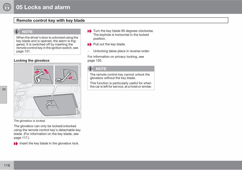
05 Locks and alarm
Remote control key with key blade
05
118
NOTE
When the driver's door is unlocked using thekey blade and is opened, the alarm is trig-gered. It is switched off by inserting theremote control key in the ignition switch, seepage 131.
Locking the glovebox
G020034
The glovebox is locked.
The glovebox can only be locked/unlockedusing the remote control key's detachable keyblade. (For information on the key blade, seepage 117.)
Insert the key blade in the glovebox lock.
Turn the key blade 90 degrees clockwise.The keyhole is horizontal in the lockedposition.
Pull out the key blade.
� Unlocking takes place in reverse order.
For information on privacy locking, seepage 120.
NOTE
The remote control key cannot unlock theglovebox without the key blade.
This function is particularly useful for whenthe car is left for service, at a hotel or similar.
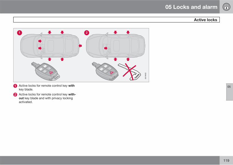
05 Locks and alarm
Active locks
05
119
G019422
Active locks for remote control key with
key blade.
Active locks for remote control key with-
out key blade and with privacy lockingactivated.
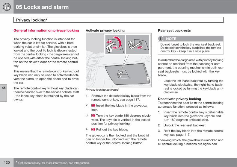
05 Locks and alarm
Privacy locking*
05
120 * Option/accessory, for more information, see Introduction.
General information on privacy locking
The privacy locking function is intended forwhen the car is left for service, with a hotelparking valet or similar. The glovebox is thenlocked and the boot lid lock is disconnectedfrom the central locking - the cargo area cannotbe opened with either the central locking but-ton on the driver's door or the remote controlkey.
This means that the remote control key withoutkey blade can only be used to activate/deacti-vate the alarm, to open the doors and to drivethe car.
The remote control key without key blade canthen be handed over to the service or hotel staff- the loose key blade is retained by the carowner.
Activate privacy locking
G020032
Privacy locking activated.
1. Remove the detachable key blade from theremote control key, see page 117.
2. Insert the key blade in the gloveboxlock.
3. Turn the key blade 180 degrees clock-wise. The keyhole is vertical in the lockedposition for privacy locking.
4. Pull out the key blade.
The glovebox is then locked and the boot lidcan no longer be unlocked with the remotecontrol key or the central locking button.
Rear seat backrests
NOTE
Do not forget to lock the rear seat backrest.Do not reinsert the key blade into the remotecontrol key - keep it in a safe place.
In order that the cargo area with privacy lockingcannot be reached from the passenger com-partment, the opening mechanism in both rearseat backrests must be locked with the keyblade.
� Lock the left-hand backrest by turning thekey blade clockwise, the right-hand back-rest is locked by turning the key blade anti-clockwise.
Deactivate privacy locking
To reconnect the boot lid to the central lockingautomatic function, proceed as follows:
1. Insert the remote control key's detachablekey blade into the glovebox keyhole andturn 180 degrees anticlockwise.
2. Unlock the rear seat backrest.
3. Refit the key blade into the remote controlkey, see page 117.
Following which, the glovebox is unlocked andall central locking functions are again con-
05 Locks and alarm
Privacy locking*
05
* Option/accessory, for more information, see Introduction. 121
trolled by the remote control key and the cen-tral locking button on the driver's door.
For information on locking the glovebox only,see page 118.
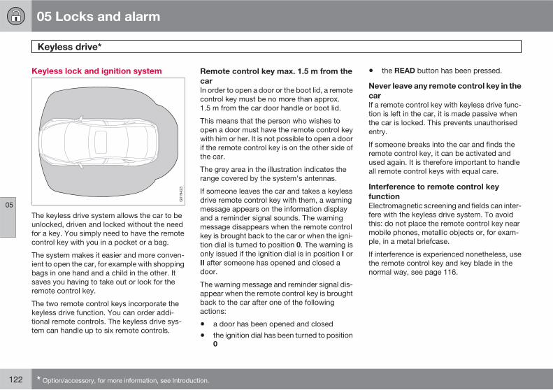
05 Locks and alarm
Keyless drive*
05
122 * Option/accessory, for more information, see Introduction.
Keyless lock and ignition system
G019423
The keyless drive system allows the car to beunlocked, driven and locked without the needfor a key. You simply need to have the remotecontrol key with you in a pocket or a bag.
The system makes it easier and more conven-ient to open the car, for example with shoppingbags in one hand and a child in the other. Itsaves you having to take out or look for theremote control key.
The two remote control keys incorporate thekeyless drive function. You can order addi-tional remote controls. The keyless drive sys-tem can handle up to six remote controls.
Remote control key max. 1.5 m from the
car
In order to open a door or the boot lid, a remotecontrol key must be no more than approx.1.5 m from the car door handle or boot lid.
This means that the person who wishes toopen a door must have the remote control keywith him or her. It is not possible to open a doorif the remote control key is on the other side ofthe car.
The grey area in the illustration indicates therange covered by the system's antennas.
If someone leaves the car and takes a keylessdrive remote control key with them, a warningmessage appears on the information displayand a reminder signal sounds. The warningmessage disappears when the remote controlkey is brought back to the car or when the igni-tion dial is turned to position 0. The warning isonly issued if the ignition dial is in position I orII after someone has opened and closed adoor.
The warning message and reminder signal dis-appear when the remote control key is broughtback to the car after one of the followingactions:
• a door has been opened and closed
• the ignition dial has been turned to position0
• the READ button has been pressed.
Never leave any remote control key in the
car
If a remote control key with keyless drive func-tion is left in the car, it is made passive whenthe car is locked. This prevents unauthorisedentry.
If someone breaks into the car and finds theremote control key, it can be activated andused again. It is therefore important to handleall remote control keys with equal care.
Interference to remote control key
function
Electromagnetic screening and fields can inter-fere with the keyless drive system. To avoidthis: do not place the remote control key nearmobile phones, metallic objects or, for exam-ple, in a metal briefcase.
If interference is experienced nonetheless, usethe remote control key and key blade in thenormal way, see page 116.
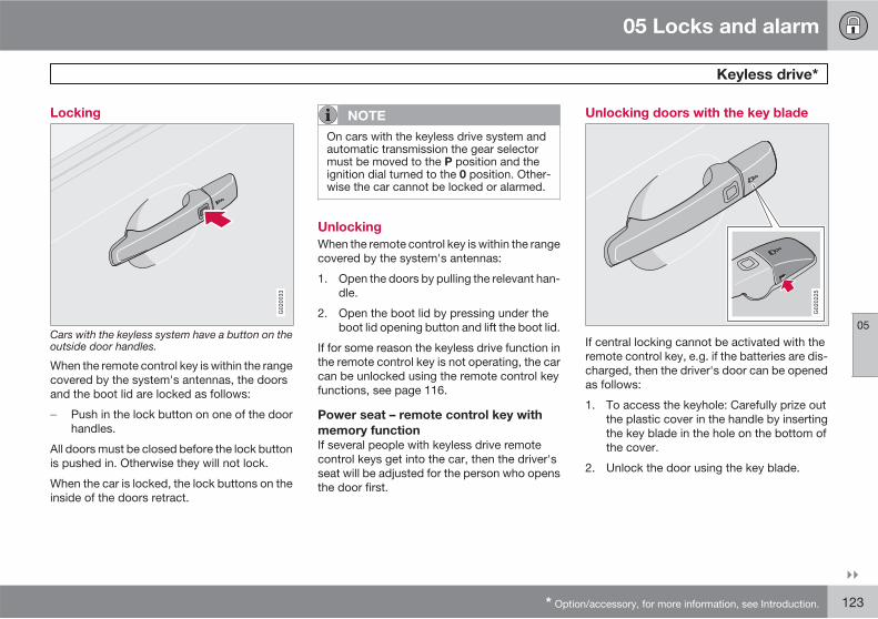
05 Locks and alarm
Keyless drive*
05
��
* Option/accessory, for more information, see Introduction. 123
Locking
G020033
Cars with the keyless system have a button on theoutside door handles.
When the remote control key is within the rangecovered by the system's antennas, the doorsand the boot lid are locked as follows:
� Push in the lock button on one of the doorhandles.
All doors must be closed before the lock buttonis pushed in. Otherwise they will not lock.
When the car is locked, the lock buttons on theinside of the doors retract.
NOTE
On cars with the keyless drive system andautomatic transmission the gear selectormust be moved to the P position and theignition dial turned to the 0 position. Other-wise the car cannot be locked or alarmed.
Unlocking
When the remote control key is within the rangecovered by the system's antennas:
1. Open the doors by pulling the relevant han-dle.
2. Open the boot lid by pressing under theboot lid opening button and lift the boot lid.
If for some reason the keyless drive function inthe remote control key is not operating, the carcan be unlocked using the remote control keyfunctions, see page 116.
Power seat – remote control key with
memory function
If several people with keyless drive remotecontrol keys get into the car, then the driver'sseat will be adjusted for the person who opensthe door first.
Unlocking doors with the key blade
G020225
If central locking cannot be activated with theremote control key, e.g. if the batteries are dis-charged, then the driver's door can be openedas follows:
1. To access the keyhole: Carefully prize outthe plastic cover in the handle by insertingthe key blade in the hole on the bottom ofthe cover.
2. Unlock the door using the key blade.
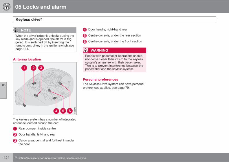
05 Locks and alarm
Keyless drive*
05
124 * Option/accessory, for more information, see Introduction.
NOTE
When the driver's door is unlocked using thekey blade and is opened, the alarm is trig-gered. It is switched off by inserting theremote control key in the ignition switch, seepage 131.
Antenna location
G020076
The keyless system has a number of integratedantennae located around the car:
Rear bumper, inside centre
Door handle, left-hand rear
Cargo area, central and furthest in underthe floor
Door handle, right-hand rear
Centre console, under the rear section
Centre console, under the front section
WARNING
People with pacemaker operations shouldnot come closer than 22 cm to the keylesssystem's antennae with their pacemaker.This is to prevent interference between thepacemaker and the keyless system.
Personal preferences
The Keyless Drive system can have personalpreferences applied, see page 79.
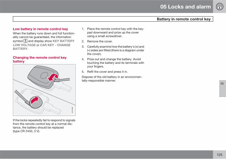
05 Locks and alarm
Battery in remote control key
05
125
Low battery in remote control key
When the battery runs down and full function-ality cannot be guaranteed, the informationsymbol and display show KEY BATTERY
LOW VOLTAGE or CAR KEY - CHANGE
BATTERY.
Changing the remote control keybattery
G019406
If the locks repeatedly fail to respond to signalsfrom the remote control key at a normal dis-tance, the battery should be replaced(type CR 2450, 3 V).
1. Place the remote control key with the key-pad downward and prize up the coverusing a small screwdriver.
2. Remove the cover.
3. Carefully examine how the battery's (+) and(–) sides are fitted (there is a diagram underthe cover).
4. Prize out and change the battery. Avoidtouching the battery and its terminals withyour fingers.
5. Refit the cover and press it in.
Dispose of the old battery in an environmen-tally-responsible manner.
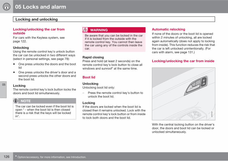
05 Locks and alarm
Locking and unlocking
05
126 * Option/accessory, for more information, see Introduction.
Locking/unlocking the car fromoutside
For cars with the Keyless system, seepage 122.
Unlocking
Using the remote control key's unlock buttonthe car can be unlocked in two different ways(select in personal settings, see page 79):
• One press unlocks the doors and the bootlid
• One press unlocks the driver's door and asecond press unlocks the other doors andthe boot lid.
Locking
The remote control key's lock button locks thedoors and boot lid simultaneously.
NOTE
The car can be locked even if the boot lid isopen * - when the boot lid is then closedthere is a risk that the keys will be lockedin*.
WARNING
Be aware that you can be locked in the carif it is locked from the outside with theremote control key. You cannot then leavethe car using any of the controls inside thecar.
Rapid closing
Press and hold (at least 2 seconds) on theremote control key's lock button to close allwindows and sunroof* at the same time.
Boot lid
Unlocking
Unlocking boot lid only:
� Press the remote control key's button tounlock the boot lid.
Locking
If the doors are locked when the boot lid isclosed then it remains unlocked. Lock with theremote control key's lock button or from insideto lock both doors and the boot lid.
Automatic relocking
If none of the doors or the boot lid is openedwithin 2 minutes of unlocking, all are lockedagain automatically (does not apply to lockingfrom inside). This function reduces the risk thatthe car is left unlocked unintentionally. (Forcars with alarm, see page 131.)
Locking/unlocking the car from inside
G007451
With the central locking button on the driver'sdoor, the doors and boot lid can be locked orunlocked simultaneously.
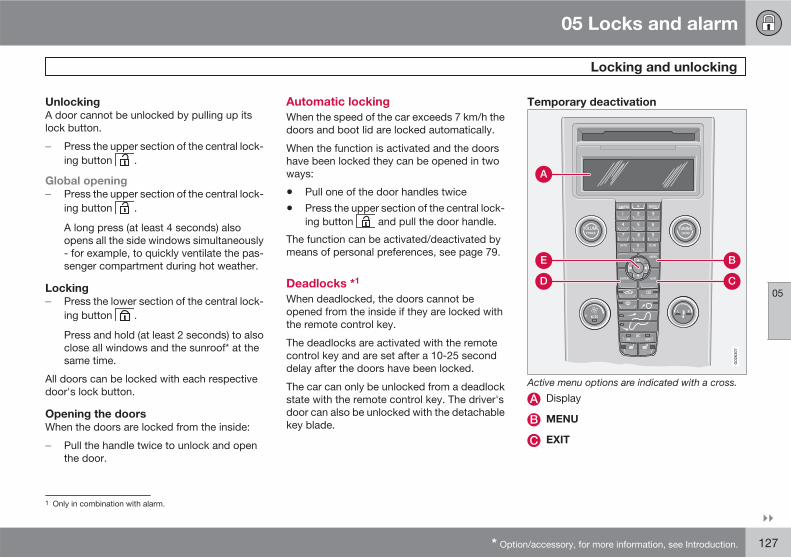
05 Locks and alarm
Locking and unlocking
05
��
* Option/accessory, for more information, see Introduction. 127
Unlocking
A door cannot be unlocked by pulling up itslock button.
� Press the upper section of the central lock-ing button .
Global opening
� Press the upper section of the central lock-ing button .
A long press (at least 4 seconds) alsoopens all the side windows simultaneously- for example, to quickly ventilate the pas-senger compartment during hot weather.
Locking
� Press the lower section of the central lock-ing button .
Press and hold (at least 2 seconds) to alsoclose all windows and the sunroof* at thesame time.
All doors can be locked with each respectivedoor's lock button.
Opening the doors
When the doors are locked from the inside:
� Pull the handle twice to unlock and openthe door.
Automatic locking
When the speed of the car exceeds 7 km/h thedoors and boot lid are locked automatically.
When the function is activated and the doorshave been locked they can be opened in twoways:
• Pull one of the door handles twice
• Press the upper section of the central lock-ing button and pull the door handle.
The function can be activated/deactivated bymeans of personal preferences, see page 79.
Deadlocks *1
When deadlocked, the doors cannot beopened from the inside if they are locked withthe remote control key.
The deadlocks are activated with the remotecontrol key and are set after a 10-25 seconddelay after the doors have been locked.
The car can only be unlocked from a deadlockstate with the remote control key. The driver'sdoor can also be unlocked with the detachablekey blade.
Temporary deactivation
A
D
B
C
E
G02
6307
Active menu options are indicated with a cross.
Display
MENU
EXIT
1 Only in combination with alarm.
05 Locks and alarm
Locking and unlocking
05
128 * Option/accessory, for more information, see Introduction.
ENTER
Navigation
If someone is going to stay in the car but thedoors must be locked from the outside, thenthe deadlocks function can be temporarilyswitched off.
This is carried out as follows:
1. Access the menu system under Car
settings (for a detailed description of themenu system, see page 79).
2. Select Reduced guard.
3. Select Activate once: The instrumentpanel display shows the messageReduced guard - See manual and thedeadlocks function is switched off whenthe car is locked.
or
Select Ask on exit: Each time the key isturned to position 0 the audio system dis-play shows the message Press ENTER to
reduce guard until engine is started.
EXIT to cancel - select one of the options:
• If the deadlocks function shall be switchedoff: Press ENTER and lock the car. Notethat the alarm's* movement and tilt detec-tors are switched off at the same time, seepage 131.
The next time the remote control key is turnedto key position II the system is reset to zero andthe instrument panel display shows the mes-sage Full guard at which the deadlocks func-tion and the alarm's movement and tilt detec-tors* are re-engaged.
or
• If the locking system shall not be changed:Select no options at all and lock the car. Orpress EXIT and lock the car.
NOTE
• Remember that the car's alarm is armedwhen the car is locked.
• If any of the doors are opened from theinside then the alarm will be triggered.
WARNING
Do not allow anyone to remain in the carwithout first deactivating the deadlocks toavoid the risk of anyone being locked in.
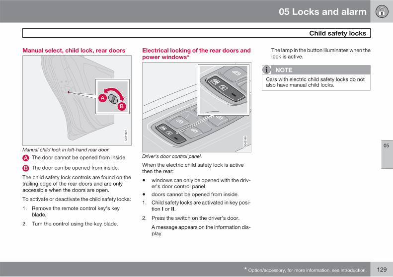
05 Locks and alarm
Child safety locks
05
* Option/accessory, for more information, see Introduction. 129
Manual select, child lock, rear doors
G014697
Manual child lock in left-hand rear door.
The door cannot be opened from inside.
The door can be opened from inside.
The child safety lock controls are found on thetrailing edge of the rear doors and are onlyaccessible when the doors are open.
To activate or deactivate the child safety locks:
1. Remove the remote control key's keyblade.
2. Turn the control using the key blade.
Electrical locking of the rear doors andpower windows*
Driver's door control panel.
When the electric child safety lock is activethen the rear:
• windows can only be opened with the driv-er's door control panel
• doors cannot be opened from inside.
1. Child safety locks are activated in key posi-tion I or II.
2. Press the switch on the driver's door.
A message appears on the information dis-play.
The lamp in the button illuminates when thelock is active.
NOTE
Cars with electric child safety locks do notalso have manual child locks.
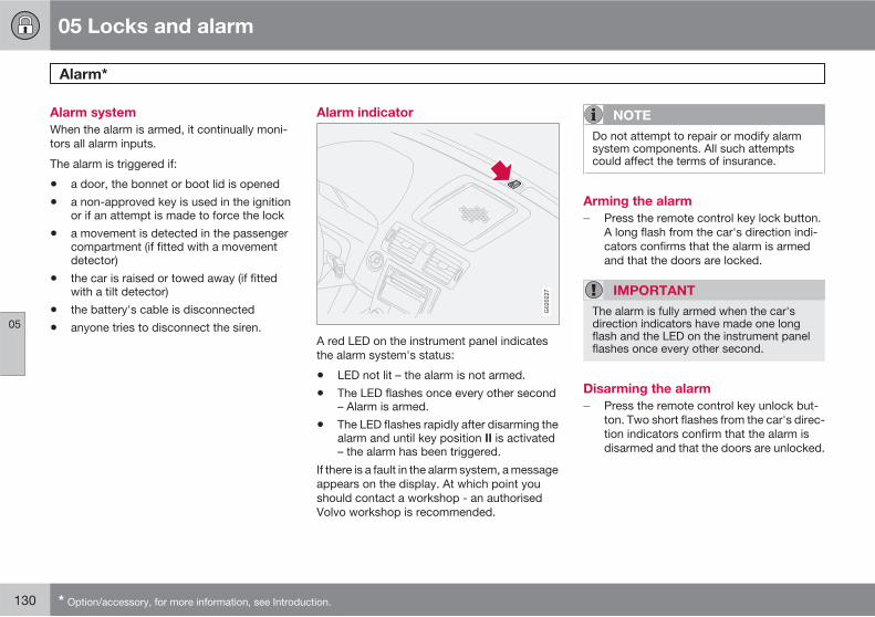
05 Locks and alarm
Alarm*
05
130 * Option/accessory, for more information, see Introduction.
Alarm system
When the alarm is armed, it continually moni-tors all alarm inputs.
The alarm is triggered if:
• a door, the bonnet or boot lid is opened
• a non-approved key is used in the ignitionor if an attempt is made to force the lock
• a movement is detected in the passengercompartment (if fitted with a movementdetector)
• the car is raised or towed away (if fittedwith a tilt detector)
• the battery's cable is disconnected
• anyone tries to disconnect the siren.
Alarm indicator
G020227
A red LED on the instrument panel indicatesthe alarm system's status:
• LED not lit – the alarm is not armed.
• The LED flashes once every other second– Alarm is armed.
• The LED flashes rapidly after disarming thealarm and until key position II is activated– the alarm has been triggered.
If there is a fault in the alarm system, a messageappears on the display. At which point youshould contact a workshop - an authorisedVolvo workshop is recommended.
NOTE
Do not attempt to repair or modify alarmsystem components. All such attemptscould affect the terms of insurance.
Arming the alarm
� Press the remote control key lock button.A long flash from the car's direction indi-cators confirms that the alarm is armedand that the doors are locked.
IMPORTANT
The alarm is fully armed when the car'sdirection indicators have made one longflash and the LED on the instrument panelflashes once every other second.
Disarming the alarm
� Press the remote control key unlock but-ton. Two short flashes from the car's direc-tion indicators confirm that the alarm isdisarmed and that the doors are unlocked.
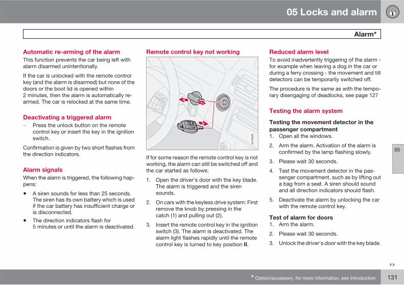
05 Locks and alarm
Alarm*
05
��
* Option/accessory, for more information, see Introduction. 131
Automatic re-arming of the alarm
This function prevents the car being left withalarm disarmed unintentionally.
If the car is unlocked with the remote controlkey (and the alarm is disarmed) but none of thedoors or the boot lid is opened within2 minutes, then the alarm is automatically re-armed. The car is relocked at the same time.
Deactivating a triggered alarm
� Press the unlock button on the remotecontrol key or insert the key in the ignitionswitch.
Confirmation is given by two short flashes fromthe direction indicators.
Alarm signals
When the alarm is triggered, the following hap-pens:
• A siren sounds for less than 25 seconds.The siren has its own battery which is usedif the car battery has insufficient charge oris disconnected.
• The direction indicators flash for5 minutes or until the alarm is deactivated.
Remote control key not working
G019420
If for some reason the remote control key is notworking, the alarm can still be switched off andthe car started as follows:
1. Open the driver's door with the key blade.The alarm is triggered and the sirensounds.
2. On cars with the keyless drive system: Firstremove the knob by pressing in thecatch (1) and pulling out (2).
3. Insert the remote control key in the ignitionswitch (3). The alarm is deactivated. Thealarm light flashes rapidly until the remotecontrol key is turned to key position II.
Reduced alarm level
To avoid inadvertently triggering of the alarm -for example when leaving a dog in the car orduring a ferry crossing - the movement and tiltdetectors can be temporarily switched off.
The procedure is the same as with the tempo-rary disengaging of deadlocks, see page 127
Testing the alarm system
Testing the movement detector in the
passenger compartment
1. Open all the windows.
2. Arm the alarm. Activation of the alarm isconfirmed by the lamp flashing slowly.
3. Please wait 30 seconds.
4. Test the movement detector in the pas-senger compartment, such as by lifting outa bag from a seat. A siren should soundand all direction indicators should flash.
5. Deactivate the alarm by unlocking the carwith the remote control key.
Test of alarm for doors
1. Arm the alarm.
2. Please wait 30 seconds.
3. Unlock the driver's door with the key blade.
05 Locks and alarm
Alarm*
05
132 * Option/accessory, for more information, see Introduction.
4. Open one of the doors. A siren shouldsound and all direction indicators shouldflash.
5. Deactivate the alarm by unlocking the carwith the remote control key.
Test of alarm for bonnet
1. Sit in the car and deactivate the movementdetector.
2. Arm the alarm. Remain in the car and lockthe doors with the button on the remotecontrol key.
3. Please wait 30 seconds.
4. Open the bonnet with the handle under thedashboard. A siren should sound and alldirection indicators should flash.
5. Deactivate the alarm by unlocking the carwith the remote control key.
05 Locks and alarm
05
133
134 * Option/accessory, for more information, see Introduction.
General.................................................................................................. 136Refuelling.............................................................................................. 138Alcoguard * ......................................................................................... 142Starting the engine ............................................................................... 146Starting the engine – Flexifuel............................................................... 148Keyless drive*........................................................................................ 150Manual gearbox.................................................................................... 151Automatic gearbox................................................................................ 152Brake system........................................................................................ 157DSTC – Stability and traction control system* ..................................... 159Park Assist*........................................................................................... 161BLIS* – Blind Spot Information System ............................................... 163Towing and recovery............................................................................. 166Start assistance.................................................................................... 168Driving with a trailer.............................................................................. 169Towing equipment* .............................................................................. 171Detachable towbar* ............................................................................. 173Loading................................................................................................. 177Adjusting headlamp pattern ................................................................. 178
STARTING AND DRIVING
06 Starting and driving
General
06
136 * Option/accessory, for more information, see Introduction.
Economical driving
Driving economically means driving smoothlywhile thinking ahead and adjusting your drivingstyle and speed to the prevailing conditions.For more advice on reducing environmentalimpact. see page 14.
• Do not run the engine to operating tem-perature at idling speed, but rather drivewith a light load as soon as possible - acold engine consumes more fuel than awarm one.
• Use the parking heater* in cold weather -the engine reaches normal operating tem-perature more quickly.
• Avoid sudden unnecessary accelerationand heavy braking.
• Do not drive with unnecessary loads in thecar.
• Remove the load carriers when not in use.
• Do not use winter tyres when the winterseason is over.
• Avoid driving with open windows.
Slippery driving conditions
Practise driving on slippery surfaces undercontrolled conditions to learn how the carreacts.
Engine, gearbox and cooling system
Under special conditions, for example harddriving in hilly terrain and hot climate, there isa risk that the engine and drive system mayoverheat - in particular with a heavy load.
For supplementary information about over-heating when driving with a trailer, seepage 169.
• In the event of a risk of overheating a built-in protection function in the gearbox is acti-vated which, amongst other things, illumi-nates the instrument panel's yellow infor-mation lamp and there is a text messagedisplayed there regarding appropriateaction - follow the recommendation given.
• If the temperature gauge for the engine'scooling system goes into the red zone -stop and let the engine idle for a fewminutes.
• Remove any auxiliary lamps from in frontof the grille when driving in hot climates.
• If the car overheats, the air conditioningmay be switched off temporarily.
• Do not turn the engine off immediately youstop after a hard drive.
NOTE
It is normal for the engine's cooling fan tooperate for a while after the engine has beenswitched off.
Diesel engine 1.6D
When driving with a major load in a hot climate,the engine cooling fan can be replaced withone of a greater capacity than the standardmodel. Check with your nearest Volvo dealerregarding the options for your car.
Open boot lid
WARNING
Do not drive with the boot lid open. Toxicexhaust fumes can be drawn into the carthrough the cargo area.
Driving in water
The car can be driven through water at a maxi-mum depth of 25 cm at a maximum speed of10 km/h. Extra caution should be exercisedwhen passing through flowing water.
06 Starting and driving
General
06
137
IMPORTANT
Engine damage can occur if water entersthe air filter.
In greater depths, water can enter the trans-mission. This reduces the lubricating abilityof the oils and shortens the service life of thesystems.
When driving in water, maintain a low speedand do not stop the car. When the water hasbeen passed, depress the brake pedal lightlyand check that full brake function is achieved.Water and mud for example can make thebrake linings wet resulting in delayed brakefunction.
Clean the electric contacts of the electricengine block heater and trailer coupling afterdriving in water and mud.
IMPORTANT
Do not let the car stand with water over thesills for any long period of time. This couldcause electrical malfunctions.
In the event of stalling in water, do not try torestart. Tow the car from the water.
Do not overload the battery
The electrical functions in the car load the bat-tery to varying degrees. Avoid having theremote control key in key position II when theengine is switched off. Instead use the I mode- which uses less power.
Note that the 12 volt outlet in the cargo areasupplies power even when the remote controlkey has been removed from the ignition switch.
Also, be aware of different accessories thatload the electrical system. Do not use functionswhich use a lot of power when the engine isswitched off. Examples of such functions are:
• ventilation fan
• windscreen wipers
• audio system (high volume)
• headlamps.
If the battery voltage is low the information dis-play shows the text LOW BATTERY POWER
SAVE MODE. The energy-saving functionthen shuts down certain functions or reducescertain functions such as the ventilation fanand/or audio system.
� In which case, charge the battery by star-ting the engine and then running it for atleast 15 minutes - battery charging is moreeffective during driving than running theengine at idling speed while stationary.
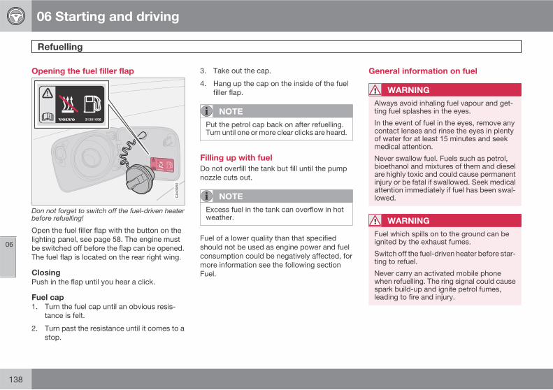
06 Starting and driving
Refuelling
06
138
Opening the fuel filler flap
Don not forget to switch off the fuel-driven heaterbefore refuelling!
Open the fuel filler flap with the button on thelighting panel, see page 58. The engine mustbe switched off before the flap can be opened.The fuel flap is located on the rear right wing.
Closing
Push in the flap until you hear a click.
Fuel cap
1. Turn the fuel cap until an obvious resis-tance is felt.
2. Turn past the resistance until it comes to astop.
3. Take out the cap.
4. Hang up the cap on the inside of the fuelfiller flap.
NOTE
Put the petrol cap back on after refuelling.Turn until one or more clear clicks are heard.
Filling up with fuel
Do not overfill the tank but fill until the pumpnozzle cuts out.
NOTE
Excess fuel in the tank can overflow in hotweather.
Fuel of a lower quality than that specifiedshould not be used as engine power and fuelconsumption could be negatively affected, formore information see the following sectionFuel.
General information on fuel
WARNING
Always avoid inhaling fuel vapour and get-ting fuel splashes in the eyes.
In the event of fuel in the eyes, remove anycontact lenses and rinse the eyes in plentyof water for at least 15 minutes and seekmedical attention.
Never swallow fuel. Fuels such as petrol,bioethanol and mixtures of them and dieselare highly toxic and could cause permanentinjury or be fatal if swallowed. Seek medicalattention immediately if fuel has been swal-lowed.
WARNING
Fuel which spills on to the ground can beignited by the exhaust fumes.
Switch off the fuel-driven heater before star-ting to refuel.
Never carry an activated mobile phonewhen refuelling. The ring signal could causespark build-up and ignite petrol fumes,leading to fire and injury.
06 Starting and driving
Refuelling
06
��
139
IMPORTANT
Mixing different types of fuel or the use offuel not recommended invalidates Volvo'sguarantees, and any associated serviceagreement. This applies to all engines.NOTE: It does not apply to cars with enginesthat are adapted to run on ethanol fuel (E85).
CO2 emissions, fuel consumption and tank vol-ume, see page 280
Catalytic converter
The purpose of the catalytic converter is topurify exhaust gases. It is located in the flow ofexhaust gases close to the engine so that itquickly reaches operating temperature. Thecatalytic converter consists of a monolith(ceramic or metal) with channels. The channelwalls are lined with a thin layer of platinum/rho-dium/palladium. These metals act as catalysts,i.e. they participate in and accelerate a chem-ical reaction without being used up them-selves.
Lambda-sondTM oxygen sensor
The Lambda-sond is part of a control systemintended to reduce emissions and improve fueleconomy.
An oxygen sensor monitors the oxygen contentof the exhaust gases leaving the engine. Thisvalue is fed into an electronic system that con-
tinuously controls the injectors. The ratio of fuelto air directed to the engine is continuouslyadjusted. These adjustments create optimalconditions for efficient combustion of harmfulemissions (hydrocarbons, carbon monoxideand nitrous oxides) using the three-way cata-lytic converter.
Petrol
Petrol must meet the EN 228 standard. Mostengines can be run with octane ratings of 91,95 and 98 RON.
• 91 RON must not be used for 4-cylinderengines and should only be used in excep-tional cases with other engines.
• 95 RON can be used for normal driving.
• 98 RON is recommended for optimum per-formance and minimum fuel consumption.
When driving in temperatures above +38 °C,fuel with the highest possible octane rating isrecommended for optimum performance andfuel economy.
IMPORTANT
• Always refuel with unleaded petrol so asnot to damage the catalytic converter.
• Do not use additives not recommendedby Volvo.
Bioethanol E85
Do not modify the fuel system or its compo-nents, and do not replace components withparts that are not specifically designed for usewith bioethanol.
WARNING
Methanol must not be used. A decal on theinside of the fuel filler flap shows the correctalternative fuel.
The use of components not designed forbioethanol engines could cause fire, injuryor engine damage.
Reserve fuel can
The reserve fuel can should be filled with petrol,see the NOTE box, page 148.
IMPORTANT
Make sure the reserve fuel can is securelyfastened and that its cap is sealed.
WARNING
Ethanol is sensitive to sparks, and explosivegases could form in the reserve fuel can if itis refuelled with ethanol.
06 Starting and driving
Refuelling
06
140
Diesel
Diesel must meet the EN 590 or JIS K2204standards.
IMPORTANT
Only ever use fuel that fulfils the Europeandiesel standard.
IMPORTANT
Diesel type fuels which must not be used:special additives, Marine Diesel Fuel, fueloil, RME1 (Rape Methyl Ester) and vegetableoil. These fuels do not fulfil the requirementsin accordance with Volvo recommendationsand generate increased wear and enginedamage that is not covered by the Volvowarranty.
Diesel engines are sensitive to contaminants,such as excessively high volumes of sulphurparticles for example. Only use diesel fuel fromwell-known producers. Never use diesel ofdubious quality.
At low temperatures (-40 °C to -6 °C), a paraffinprecipitate may form in the diesel fuel, whichmay lead to ignition problems. Special dieselfuel designed for low temperatures aroundfreezing point is available from the major oil
companies. This fuel is less viscous at low tem-peratures and reduces the risk of paraffin pre-cipitate.
IMPORTANT
Use special winter grade fuel during coldmonths.
The risk of condensation in the fuel tank isreduced if the tank is kept well filled. Whenrefuelling, check that the area around the fuelfiller pipe is clean. Avoid spilling fuel onto thepaintwork. Wash off any spillage with deter-gent and water.
IMPORTANT
The sulphur content must be a maximum of50 ppm.
Empty tank
The design of the fuel system in a diesel enginemeans that if the vehicle runs out of fuel, thetank may need to be vented in the workshop inorder to restart the engine after fuelling.
Once the engine has stopped due to fuel star-vation, the fuel system needs a few momentsto carry out a check. Do this before starting the
engine, once the fuel tank has been filled withdiesel:
1. Insert the remote control key in the ignitionswitch and turn to key position II (seepage 146).
2. Wait approx. 1 minute.3. To start the engine: Depress the brake and/
or clutch pedal, and turn the remote controlkey to start position III.
Draining condensation from the fuel filter
The fuel filter separates condensation from thefuel. Condensation can disrupt engine opera-tion.
The fuel filter must be drained at the intervalsspecified in the Service and Warranty Bookletor if you suspect that the car has been filledwith contaminated fuel.
IMPORTANT
Certain special additives remove the waterseparation in the fuel filter.
Diesel particle filter (DPF)
Diesel cars may be equipped with a particle fil-ter, which results in more efficient emissioncontrol. The particles in the exhaust gases arecollected in the filter during normal driving. So-
1 Diesel fuel may contain a certain amount of RME, but further amounts must not be added.
06 Starting and driving
Refuelling
06
* Option/accessory, for more information, see Introduction. 141
called "regeneration" is started in order to burnaway the particles and empty the filter. Thisrequires the engine to have reached normaloperating temperature.
Regeneration of the filter takes place automat-ically at an interval of approximately300 – 900 km depending on driving conditions.Regeneration normally takes 10 - 20 minutes.It may take a little longer at a low averagespeed. Fuel consumption may increase slightlyduring regeneration.
The rear window heating may be activatedautomatically to increase the load on theengine during regeneration without warning.
Regeneration in cold weather
If the car is frequently driven short distances incold weather then the engine does not reachnormal operating temperature. This means thatregeneration of the diesel particle filter doesnot take place and the filter is not emptied.
When the filter has becomeapproximately 80% full of particles, the yellowinformation symbol on the instrument panelilluminates, and the message SOOT FILTER
FULL SEE OWNER MANUAL is shown on theinstrument panel display.
Start regeneration of the filter by driving the caruntil the engine reaches normal operating tem-perature, preferably on a main road or motor-
way. The car should then be driven for approx-imately 20 minutes more.
NOTE
A smaller reduction of engine power may benoticed temporarily during regeneration.
When regeneration is complete the message iscleared automatically.
IMPORTANT
If the filter fills up it may be incapable offunctioning. Then it can be difficult to startthe engine and there is a risk that the filterwill have to be replaced.
Use the parking heater* in cold weather so thatthe engine reaches normal operating tempera-ture more quickly.
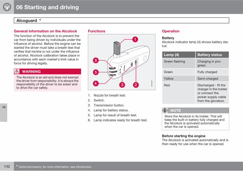
06 Starting and driving
Alcoguard *
06
142 * Option/accessory, for more information, see Introduction.
General information on the Alcolock
The function of the Alcolock is to prevent thecar from being driven by individuals under theinfluence of alcohol. Before the engine can bestarted the driver must take a breath test thatverifies that he/she is not under the influenceof alcohol. Alcolock calibration takes place inaccordance with each market's limit value inforce for driving legally.
WARNING
The Alcolock is an aid and does not exemptthe driver from responsibility. It is always theresponsibility of the driver to be sober andto drive the car safely.
Functions
1. Nozzle for breath test.2. Switch.3. Transmission button.4. Lamp for battery status.5. Lamp for result of breath test.6. Lamp indicates ready for breath test.
Operation
Battery
Alcolock indicator lamp (4) shows battery sta-tus:
Lamp (4) Battery status
Green flashing Charging in pro-gress
Green Fully charged
Yellow Semi-charged
Red Discharged - fit thecharger in the holderor connect thepower supply cablefrom the glovebox.
NOTE
Store the Alcolock in its holder. This willkeep the built-in battery fully charged andthe Alcolock is activated automaticallywhen the car is opened.
Before starting the engine
The Alcolock is activated automatically and isthen ready for use when the car is opened.
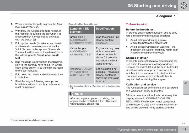
06 Starting and driving
Alcoguard *
06
��
* Option/accessory, for more information, see Introduction. 143
1. When indicator lamp (6) is green the Alco-lock is ready for use.
2. Withdraw the Alcolock from its holder. Ifthe Alcolock is outside the car when it isunlocked then it must first be activatedwith the switch (2).
3. Fold up the nozzle (1), take a deep breathand blow with an even pressure until a"click" is heard after approx. 5 seconds.The result will be one of the alternatives inthe following table Result after breath
test.4. If no message is shown then the transmis-
sion to the car may have failed - in whichcase, press button (3) to transmit the resultto the car manually.
5. Fold down the nozzle and refit the Alcolockin its holder.
6. Start the engine following an approvedbreath test within 5 minutes - otherwise itmust be repeated.
Result after breath test
Lamp (5) + Dis-play text
Specification
Green lamp +ALCOGUARD
APPROVED TEST
Start the engine - noalcohol contentmeasured.
Yellow lamp +ALCOGUARD
APPROVED TEST
Engine starting pos-sible - measuredalcohol content isabove 0.1 promillebut below the limitvalue in forceA.
Red lamp + DISAP-
PROVED TEST
WAIT 1 MINUTE
Engine starting notpossible - measuredalcohol content isabove the limit valuein forceA.
A See the section, General information on the Alcolock, page142
NOTE
After a completed period of driving, theengine can be restarted within 30 minuteswithout a new breath test.
To bear in mind
Before the breath test
In order to obtain correct function and as accu-rate a measurement result as possible:
• Avoid eating or drinking approx.5 minutes before the breath test.
• Avoid excess windscreen washing - thealcohol in the washer fluid may result in anincorrect measurement result.
Change of driver
In order to ensure that a new breath test is car-ried out in the event of a change of driver -depress the switch (2) and the send button (3)simultaneously for approx. 3 seconds. Atwhich point the car returns to start inhibitionmode and a new approved breath test isrequired before starting the engine.
Calibration and service
The Alcolock must be checked and calibratedat a workshop1 every 12 months.
30 days before recalibration is necessary thedisplay shows ALCOGUARD CALIBR.
REQUIRED. If calibration is not carried outwithin these 30 days then normal engine star-ting will be blocked - only starting with the
1 An authorised Volvo workshop is recommended.
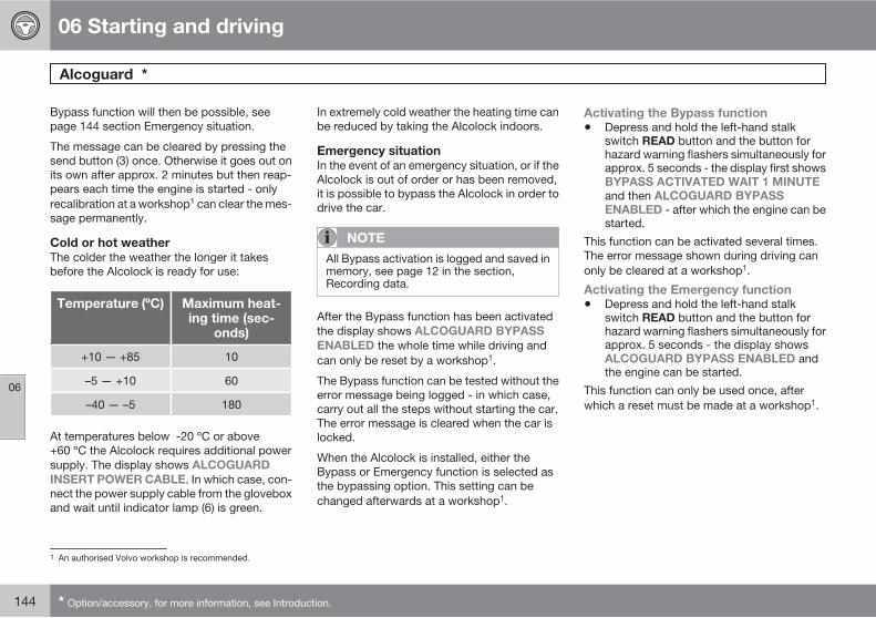
06 Starting and driving
Alcoguard *
06
144 * Option/accessory, for more information, see Introduction.
Bypass function will then be possible, seepage 144 section Emergency situation.
The message can be cleared by pressing thesend button (3) once. Otherwise it goes out onits own after approx. 2 minutes but then reap-pears each time the engine is started - onlyrecalibration at a workshop1 can clear the mes-sage permanently.
Cold or hot weather
The colder the weather the longer it takesbefore the Alcolock is ready for use:
Temperature (ºC) Maximum heat-ing time (sec-
onds)
+10 — +85 10
–5 — +10 60
–40 — –5 180
At temperatures below -20 ºC or above+60 ºC the Alcolock requires additional powersupply. The display shows ALCOGUARD
INSERT POWER CABLE. In which case, con-nect the power supply cable from the gloveboxand wait until indicator lamp (6) is green.
In extremely cold weather the heating time canbe reduced by taking the Alcolock indoors.
Emergency situation
In the event of an emergency situation, or if theAlcolock is out of order or has been removed,it is possible to bypass the Alcolock in order todrive the car.
NOTE
All Bypass activation is logged and saved inmemory, see page 12 in the section,Recording data.
After the Bypass function has been activatedthe display shows ALCOGUARD BYPASS
ENABLED the whole time while driving andcan only be reset by a workshop1.
The Bypass function can be tested without theerror message being logged - in which case,carry out all the steps without starting the car.The error message is cleared when the car islocked.
When the Alcolock is installed, either theBypass or Emergency function is selected asthe bypassing option. This setting can bechanged afterwards at a workshop1.
Activating the Bypass function
• Depress and hold the left-hand stalkswitch READ button and the button forhazard warning flashers simultaneously forapprox. 5 seconds - the display first showsBYPASS ACTIVATED WAIT 1 MINUTE
and then ALCOGUARD BYPASS
ENABLED - after which the engine can bestarted.
This function can be activated several times.The error message shown during driving canonly be cleared at a workshop1.
Activating the Emergency function
• Depress and hold the left-hand stalkswitch READ button and the button forhazard warning flashers simultaneously forapprox. 5 seconds - the display showsALCOGUARD BYPASS ENABLED andthe engine can be started.
This function can only be used once, afterwhich a reset must be made at a workshop1.
1 An authorised Volvo workshop is recommended.
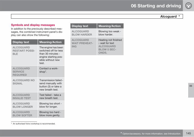
06 Starting and driving
Alcoguard *
06
* Option/accessory, for more information, see Introduction. 145
Symbols and display messages
In addition to the previously described mes-sages, the combined instrument panel's dis-play can also show the following:
Display text Meaning/Action
ALCOGUARD
RESTART POSSI-
BLE
The engine has beenswitched off for lessthan 30 minutes -engine starting pos-sible without newtest.
ALCOGUARD
SERVICE
REQUIRED
Contact a work-shop1.
ALCOGUARD NO
SIGNAL
Transmission failed -send manually withbutton (3) or take anew breath test.
ALCOGUARD
INVALID TEST
Test failed - take anew breath test.
ALCOGUARD
BLOW LONGER
Blowing too short -blow for longer.
ALCOGUARD
BLOW SOFTER
Blowing too hard -blow more gently.
Display text Meaning/Action
ALCOGUARD
BLOW HARDER
Blowing too weak -blow harder.
ALCOGUARD
WAIT PREHEAT-
ING
Heating not finished- wait for textALCOGUARD
BLOW 5 SEC-
ONDS.
1 An authorised Volvo workshop is recommended.
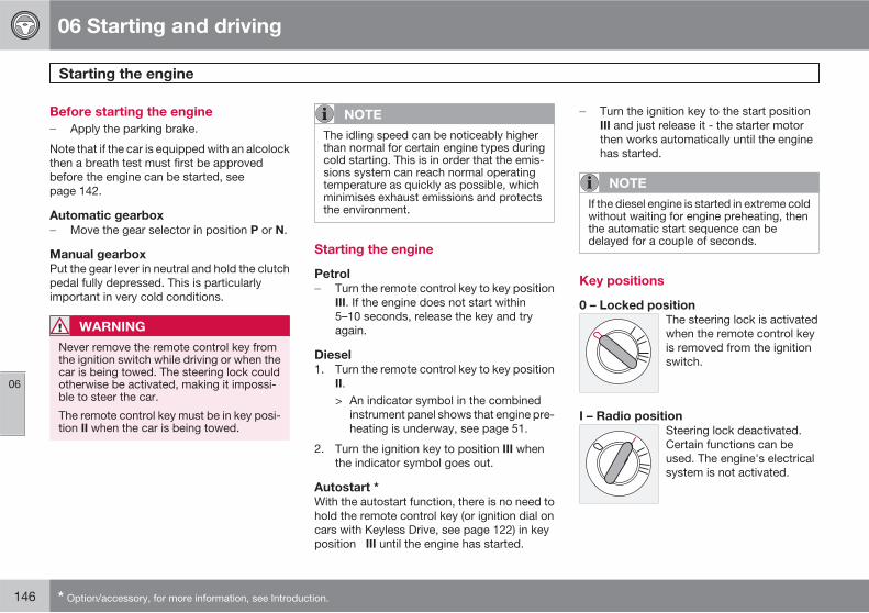
06 Starting and driving
Starting the engine
06
146 * Option/accessory, for more information, see Introduction.
Before starting the engine
� Apply the parking brake.
Note that if the car is equipped with an alcolockthen a breath test must first be approvedbefore the engine can be started, seepage 142.
Automatic gearbox
� Move the gear selector in position P or N.
Manual gearbox
Put the gear lever in neutral and hold the clutchpedal fully depressed. This is particularlyimportant in very cold conditions.
WARNING
Never remove the remote control key fromthe ignition switch while driving or when thecar is being towed. The steering lock couldotherwise be activated, making it impossi-ble to steer the car.
The remote control key must be in key posi-tion II when the car is being towed.
NOTE
The idling speed can be noticeably higherthan normal for certain engine types duringcold starting. This is in order that the emis-sions system can reach normal operatingtemperature as quickly as possible, whichminimises exhaust emissions and protectsthe environment.
Starting the engine
Petrol
� Turn the remote control key to key positionIII. If the engine does not start within5–10 seconds, release the key and tryagain.
Diesel
1. Turn the remote control key to key positionII.> An indicator symbol in the combined
instrument panel shows that engine pre-heating is underway, see page 51.
2. Turn the ignition key to position III whenthe indicator symbol goes out.
Autostart *
With the autostart function, there is no need tohold the remote control key (or ignition dial oncars with Keyless Drive, see page 122) in keyposition III until the engine has started.
� Turn the ignition key to the start positionIII and just release it - the starter motorthen works automatically until the enginehas started.
NOTE
If the diesel engine is started in extreme coldwithout waiting for engine preheating, thenthe automatic start sequence can bedelayed for a couple of seconds.
Key positions
0 – Locked position
The steering lock is activatedwhen the remote control keyis removed from the ignitionswitch.
I – Radio position
Steering lock deactivated.Certain functions can beused. The engine's electricalsystem is not activated.
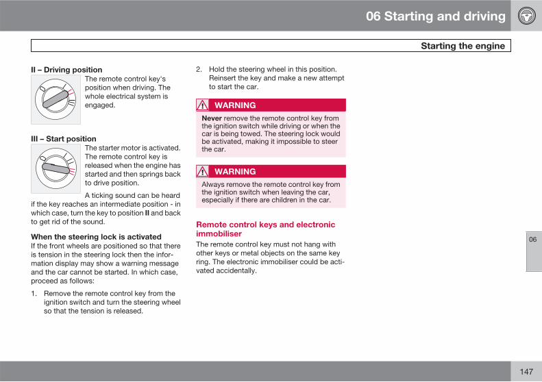
06 Starting and driving
Starting the engine
06
147
II – Driving position
The remote control key'sposition when driving. Thewhole electrical system isengaged.
III – Start position
The starter motor is activated.The remote control key isreleased when the engine hasstarted and then springs backto drive position.
A ticking sound can be heardif the key reaches an intermediate position - inwhich case, turn the key to position II and backto get rid of the sound.
When the steering lock is activated
If the front wheels are positioned so that thereis tension in the steering lock then the infor-mation display may show a warning messageand the car cannot be started. In which case,proceed as follows:
1. Remove the remote control key from theignition switch and turn the steering wheelso that the tension is released.
2. Hold the steering wheel in this position.Reinsert the key and make a new attemptto start the car.
WARNING
Never remove the remote control key fromthe ignition switch while driving or when thecar is being towed. The steering lock wouldbe activated, making it impossible to steerthe car.
WARNING
Always remove the remote control key fromthe ignition switch when leaving the car,especially if there are children in the car.
Remote control keys and electronicimmobiliser
The remote control key must not hang withother keys or metal objects on the same keyring. The electronic immobiliser could be acti-vated accidentally.
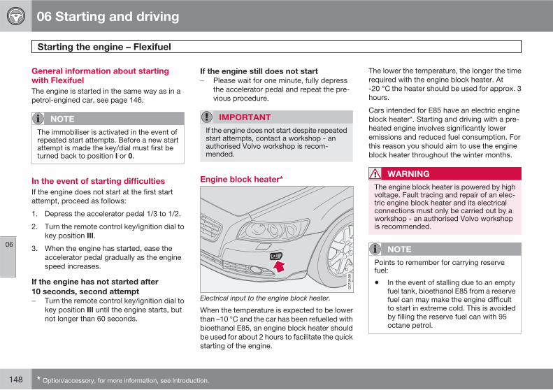
06 Starting and driving
Starting the engine – Flexifuel
06
148 * Option/accessory, for more information, see Introduction.
General information about startingwith Flexifuel
The engine is started in the same way as in apetrol-engined car, see page 146.
NOTE
The immobiliser is activated in the event ofrepeated start attempts. Before a new startattempt is made the key/dial must first beturned back to position I or 0.
In the event of starting difficulties
If the engine does not start at the first startattempt, proceed as follows:
1. Depress the accelerator pedal 1/3 to 1/2.
2. Turn the remote control key/ignition dial tokey position III.
3. When the engine has started, ease theaccelerator pedal gradually as the enginespeed increases.
If the engine has not started after
10 seconds, second attempt
� Turn the remote control key/ignition dial tokey position III until the engine starts, butnot longer than 60 seconds.
If the engine still does not start
� Please wait for one minute, fully depressthe accelerator pedal and repeat the pre-vious procedure.
IMPORTANT
If the engine does not start despite repeatedstart attempts, contact a workshop - anauthorised Volvo workshop is recom-mended.
Engine block heater*
Electrical input to the engine block heater.
When the temperature is expected to be lowerthan –10 °C and the car has been refuelled withbioethanol E85, an engine block heater shouldbe used for about 2 hours to facilitate the quickstarting of the engine.
The lower the temperature, the longer the timerequired with the engine block heater. At-20 °C the heater should be used for approx. 3hours.
Cars intended for E85 have an electric engineblock heater*. Starting and driving with a pre-heated engine involves significantly loweremissions and reduced fuel consumption. Forthis reason you should aim to use the engineblock heater throughout the winter months.
WARNING
The engine block heater is powered by highvoltage. Fault tracing and repair of an elec-tric engine block heater and its electricalconnections must only be carried out by aworkshop - an authorised Volvo workshopis recommended.
NOTE
Points to remember for carrying reservefuel:
• In the event of stalling due to an emptyfuel tank, bioethanol E85 from a reservefuel can may make the engine difficultto start in extreme cold. This is avoidedby filling the reserve fuel can with 95octane petrol.
06 Starting and driving
Starting the engine – Flexifuel
06
149
For more information on Flexifuel's bioethanolE85 fuel, see page 139.
Fuel adaptation
If the fuel tank is filled with petrol after the carhas been driven on bioethanol E85 (or viceversa) then the engine may run slightlyunevenly for a time. For this reason it is impor-tant to allow the engine to accustom itself(adapt) to the new fuel mixture.
Adaptation takes place automatically when thecar is driven for a short period at an evenspeed.
IMPORTANT
After the fuel mixture in the tank has beenchanged an adaptation should be made bydriving at an even speed for about 15minutes.
If the battery has been discharged or discon-nected then a slightly longer period of drivingis required for the adaptation as the memoryfor the electronics has been cleared.
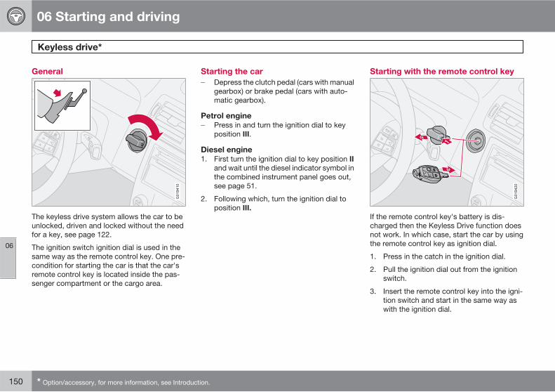
06 Starting and driving
Keyless drive*
06
150 * Option/accessory, for more information, see Introduction.
General
G019410
The keyless drive system allows the car to beunlocked, driven and locked without the needfor a key, see page 122.
The ignition switch ignition dial is used in thesame way as the remote control key. One pre-condition for starting the car is that the car'sremote control key is located inside the pas-senger compartment or the cargo area.
Starting the car
� Depress the clutch pedal (cars with manualgearbox) or brake pedal (cars with auto-matic gearbox).
Petrol engine
� Press in and turn the ignition dial to keyposition III.
Diesel engine
1. First turn the ignition dial to key position IIand wait until the diesel indicator symbol inthe combined instrument panel goes out,see page 51.
2. Following which, turn the ignition dial toposition III.
Starting with the remote control key
G019420
If the remote control key's battery is dis-charged then the Keyless Drive function doesnot work. In which case, start the car by usingthe remote control key as ignition dial.
1. Press in the catch in the ignition dial.
2. Pull the ignition dial out from the ignitionswitch.
3. Insert the remote control key into the igni-tion switch and start in the same way aswith the ignition dial.
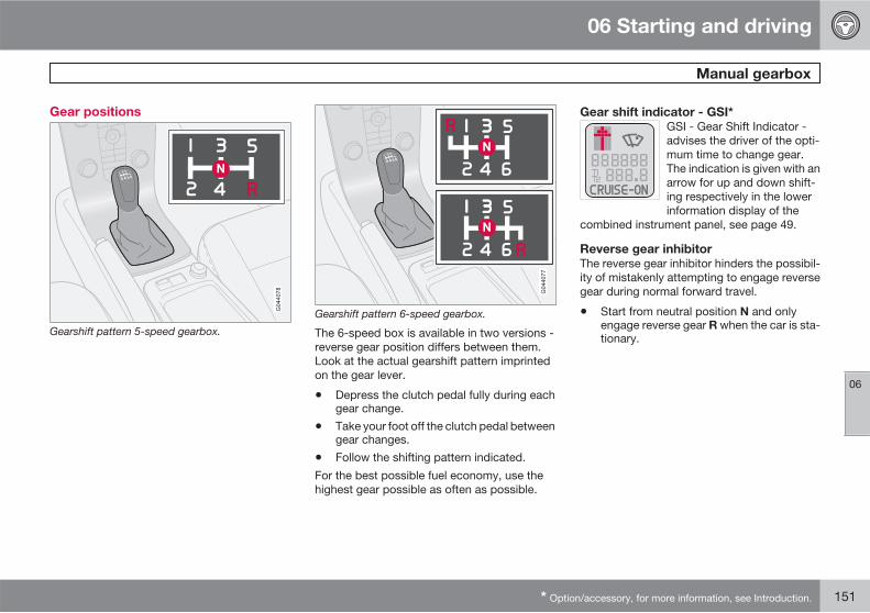
06 Starting and driving
Manual gearbox
06
* Option/accessory, for more information, see Introduction. 151
Gear positions
Gearshift pattern 5-speed gearbox.
Gearshift pattern 6-speed gearbox.
The 6-speed box is available in two versions -reverse gear position differs between them.Look at the actual gearshift pattern imprintedon the gear lever.
• Depress the clutch pedal fully during eachgear change.
• Take your foot off the clutch pedal betweengear changes.
• Follow the shifting pattern indicated.
For the best possible fuel economy, use thehighest gear possible as often as possible.
Gear shift indicator - GSI*
GSI - Gear Shift Indicator -advises the driver of the opti-mum time to change gear.The indication is given with anarrow for up and down shift-ing respectively in the lowerinformation display of the
combined instrument panel, see page 49.
Reverse gear inhibitor
The reverse gear inhibitor hinders the possibil-ity of mistakenly attempting to engage reversegear during normal forward travel.
• Start from neutral position N and onlyengage reverse gear R when the car is sta-tionary.
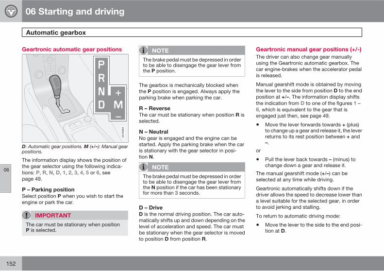
06 Starting and driving
Automatic gearbox
06
152
Geartronic automatic gear positions
G018264
D: Automatic gear positions. M (+/–): Manual gearpositions.
The information display shows the position ofthe gear selector using the following indica-tions: P, R, N, D, 1, 2, 3, 4, 5 or 6, seepage 49.
P – Parking position
Select position P when you wish to start theengine or park the car.
IMPORTANT
The car must be stationary when positionP is selected.
NOTE
The brake pedal must be depressed in orderto be able to disengage the gear lever fromthe P position.
The gearbox is mechanically blocked whenthe P position is engaged. Always apply theparking brake when parking the car.
R – Reverse
The car must be stationary when position R isselected.
N – Neutral
No gear is engaged and the engine can bestarted. Apply the parking brake when the caris stationary with the gear selector in posi-tion N.
NOTE
The brake pedal must be depressed in orderto be able to disengage the gear lever fromthe N position if the car has been stationaryfor more than 3 seconds.
D – Drive
D is the normal driving position. The car auto-matically shifts up and down depending on thelevel of acceleration and speed. The car mustbe stationary when the gear selector is movedto position D from position R.
Geartronic manual gear positions (+/-)
The driver can also change gear manuallyusing the Geartronic automatic gearbox. Thecar engine-brakes when the accelerator pedalis released.
Manual gearshift mode is obtained by movingthe lever to the side from position D to the endposition at +/–. The information display shiftsthe indication from D to one of the figures 1 –6, which is equivalent to the gear that isengaged just then, see page 49.
• Move the lever forwards towards + (plus)to change up a gear and release it, the leverreturns to its rest position between + and–.
or
• Pull the lever back towards – (minus) tochange down a gear and release it.
The manual gearshift mode (+/–) can beselected at any time while driving.
Geartronic automatically shifts down if thedriver allows the speed to decrease lower thana level suitable for the selected gear, in orderto avoid jerking and stalling.
To return to automatic driving mode:
• Move the lever to the side to the end posi-tion at D.
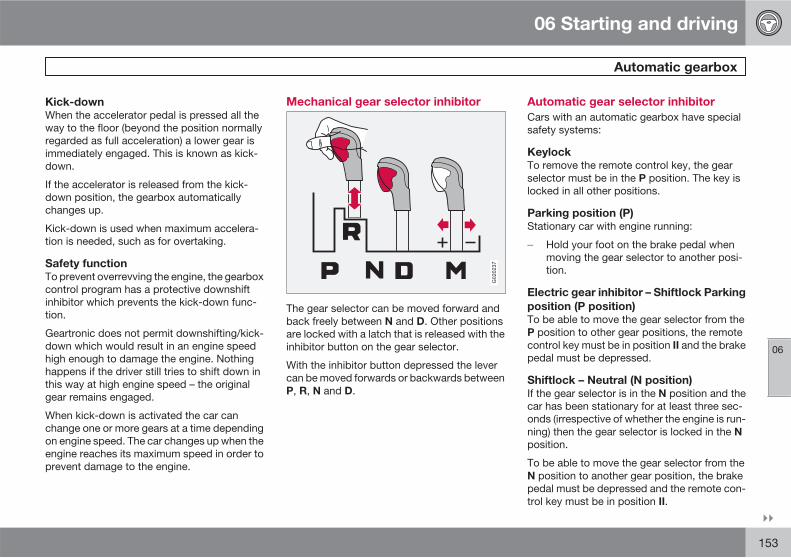
06 Starting and driving
Automatic gearbox
06
��
153
Kick-down
When the accelerator pedal is pressed all theway to the floor (beyond the position normallyregarded as full acceleration) a lower gear isimmediately engaged. This is known as kick-down.
If the accelerator is released from the kick-down position, the gearbox automaticallychanges up.
Kick-down is used when maximum accelera-tion is needed, such as for overtaking.
Safety function
To prevent overrevving the engine, the gearboxcontrol program has a protective downshiftinhibitor which prevents the kick-down func-tion.
Geartronic does not permit downshifting/kick-down which would result in an engine speedhigh enough to damage the engine. Nothinghappens if the driver still tries to shift down inthis way at high engine speed – the originalgear remains engaged.
When kick-down is activated the car canchange one or more gears at a time dependingon engine speed. The car changes up when theengine reaches its maximum speed in order toprevent damage to the engine.
Mechanical gear selector inhibitor
G020237
The gear selector can be moved forward andback freely between N and D. Other positionsare locked with a latch that is released with theinhibitor button on the gear selector.
With the inhibitor button depressed the levercan be moved forwards or backwards betweenP, R, N and D.
Automatic gear selector inhibitor
Cars with an automatic gearbox have specialsafety systems:
Keylock
To remove the remote control key, the gearselector must be in the P position. The key islocked in all other positions.
Parking position (P)
Stationary car with engine running:
� Hold your foot on the brake pedal whenmoving the gear selector to another posi-tion.
Electric gear inhibitor – Shiftlock Parking
position (P position)
To be able to move the gear selector from theP position to other gear positions, the remotecontrol key must be in position II and the brakepedal must be depressed.
Shiftlock – Neutral (N position)
If the gear selector is in the N position and thecar has been stationary for at least three sec-onds (irrespective of whether the engine is run-ning) then the gear selector is locked in the Nposition.
To be able to move the gear selector from theN position to another gear position, the brakepedal must be depressed and the remote con-trol key must be in position II.
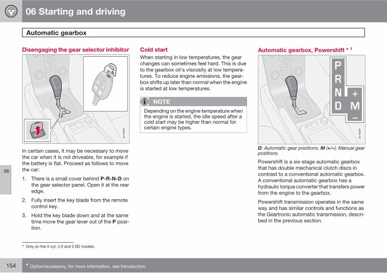
06 Starting and driving
Automatic gearbox
06
154 * Option/accessory, for more information, see Introduction.
Disengaging the gear selector inhibitor
G018263
In certain cases, it may be necessary to movethe car when it is not driveable, for example ifthe battery is flat. Proceed as follows to movethe car:
1. There is a small cover behind P-R-N-D onthe gear selector panel. Open it at the rearedge.
2. Fully insert the key blade from the remotecontrol key.
3. Hold the key blade down and at the sametime move the gear lever out of the P posi-tion.
Cold start
When starting in low temperatures, the gearchanges can sometimes feel hard. This is dueto the gearbox oil's viscosity at low tempera-tures. To reduce engine emissions, the gear-box shifts up later than normal when the engineis started at low temperatures.
NOTE
Depending on the engine temperature whenthe engine is started, the idle speed after acold start may be higher than normal forcertain engine types.
Automatic gearbox, Powershift * 1
G018264
D: Automatic gear positions. M (+/–): Manual gearpositions.
Powershift is a six-stage automatic gearboxthat has double mechanical clutch discs incontrast to a conventional automatic gearbox.A conventional automatic gearbox has ahydraulic torque converter that transfers powerfrom the engine to the gearbox.
Powershift transmission operates in the sameway and has similar controls and functions asthe Geartronic automatic transmission, descri-bed in the previous section.
1 Only on the 4-cyl. 2.0 and 2.0D models.
06 Starting and driving
Automatic gearbox
06
��
155
To bear in mind
The transmission's double clutch has overloadprotection that is activated if it becomes toohot, e.g. if the car is held stationary with theaccelerator pedal on an uphill gradient for along time.
Overheated transmission causes the car toshake and vibrate, and the warning symbol illu-minates and the information display shows amessage. The transmission can also overheatduring slow driving in queues (10 km/h orslower) on an uphill gradient, or with a trailerhitched. The transmission cools down whenthe car is stationary, with foot brake depressedand the engine running at idling speed.
Overheating during slow driving in queues canbe avoided by driving in stages: Stop the carand wait with your foot on the brake pedal untilthere is a moderate distance to the trafficahead, drive forward a short distance, and thenwait another moment with your foot on thebrake pedal.
IMPORTANT
Use the foot brake to hold the car stationaryon an uphill gradient - do not hold the carwith the accelerator pedal. The gearboxcould then overheat.
Text message and action
In some situations the display can show a mes-sage at the same time as a symbol is illumi-nated.
The table shows three steps with an increaseddegree of seriousness should the gearboxbecome too hot. In parallel with the display textthe driver is also advised that the car's elec-tronics are temporarily changing the drivingcharacteristics. Follow the instructions on theinformation display where appropriate.
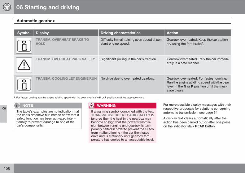
06 Starting and driving
Automatic gearbox
06
156
Symbol Display Driving characteristics Action
TRANSM. OVERHEAT BRAKE TO
HOLD
Difficulty in maintaining even speed at con-stant engine speed.
Gearbox overheated. Keep the car station-ary using the foot brakeA.
TRANSM. OVERHEAT PARK SAFELY Significant pulling in the car's traction. Gearbox overheated. Park the car immedi-ately in a safe manner.
TRANSM. COOLING LET ENGINE RUN No drive due to overheated gearbox. Gearbox overheated. For fastest cooling:Run the engine at idling speed with the gearlever in the N or P position until the mes-sage clears.
A For fastest cooling: run the engine at idling speed with the gear lever in the N or P position, until the message clears.
NOTE
The table's examples are no indication thatthe car is defective but instead show that asafety function has been activated inten-tionally to prevent damage to one of thecar's components.
WARNING
If a warning symbol combined with the textTRANSM. OVERHEAT PARK SAFELY isignored then the heat in the gearbox maybecome so high that the power transmis-sion between engine and gearbox is tem-porarily halted in order to prevent the clutchfrom malfunctioning - the car then losesdrive and is stationary until gearbox tem-perature has cooled to an acceptable level.
For more possible display messages with theirrespective proposals for solutions concerningautomatic transmission, see page 54.
A display text clears automatically after theaction has been carried out or after one presson the indicator stalk READ button.
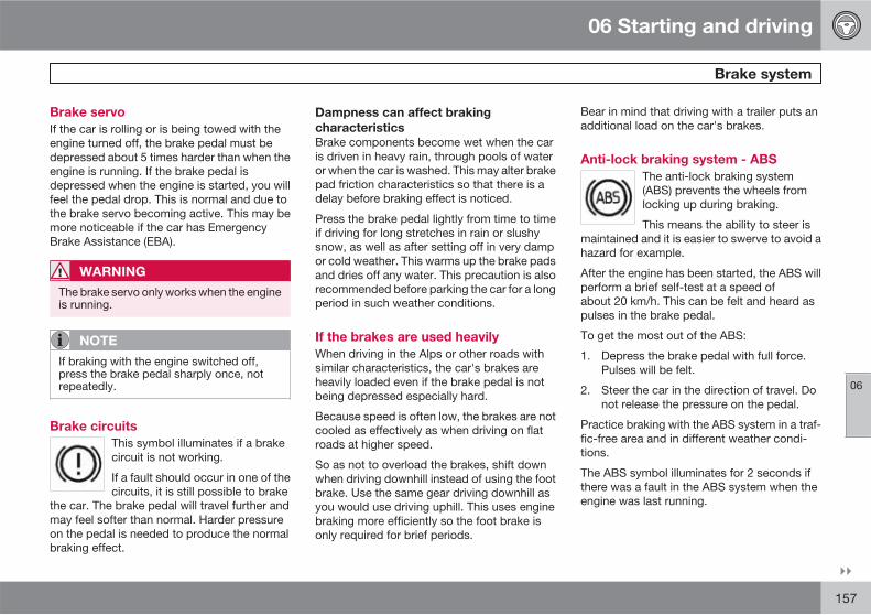
06 Starting and driving
Brake system
06
��
157
Brake servo
If the car is rolling or is being towed with theengine turned off, the brake pedal must bedepressed about 5 times harder than when theengine is running. If the brake pedal isdepressed when the engine is started, you willfeel the pedal drop. This is normal and due tothe brake servo becoming active. This may bemore noticeable if the car has EmergencyBrake Assistance (EBA).
WARNING
The brake servo only works when the engineis running.
NOTE
If braking with the engine switched off,press the brake pedal sharply once, notrepeatedly.
Brake circuits
This symbol illuminates if a brakecircuit is not working.
If a fault should occur in one of thecircuits, it is still possible to brake
the car. The brake pedal will travel further andmay feel softer than normal. Harder pressureon the pedal is needed to produce the normalbraking effect.
Dampness can affect braking
characteristics
Brake components become wet when the caris driven in heavy rain, through pools of wateror when the car is washed. This may alter brakepad friction characteristics so that there is adelay before braking effect is noticed.
Press the brake pedal lightly from time to timeif driving for long stretches in rain or slushysnow, as well as after setting off in very dampor cold weather. This warms up the brake padsand dries off any water. This precaution is alsorecommended before parking the car for a longperiod in such weather conditions.
If the brakes are used heavily
When driving in the Alps or other roads withsimilar characteristics, the car's brakes areheavily loaded even if the brake pedal is notbeing depressed especially hard.
Because speed is often low, the brakes are notcooled as effectively as when driving on flatroads at higher speed.
So as not to overload the brakes, shift downwhen driving downhill instead of using the footbrake. Use the same gear driving downhill asyou would use driving uphill. This uses enginebraking more efficiently so the foot brake isonly required for brief periods.
Bear in mind that driving with a trailer puts anadditional load on the car's brakes.
Anti-lock braking system - ABS
The anti-lock braking system(ABS) prevents the wheels fromlocking up during braking.
This means the ability to steer ismaintained and it is easier to swerve to avoid ahazard for example.
After the engine has been started, the ABS willperform a brief self-test at a speed ofabout 20 km/h. This can be felt and heard aspulses in the brake pedal.
To get the most out of the ABS:
1. Depress the brake pedal with full force.Pulses will be felt.
2. Steer the car in the direction of travel. Donot release the pressure on the pedal.
Practice braking with the ABS system in a traf-fic-free area and in different weather condi-tions.
The ABS symbol illuminates for 2 seconds ifthere was a fault in the ABS system when theengine was last running.
06 Starting and driving
Brake system
06
158
Emergency Brake Assistance – EBA
For sudden braking, EBA (Emergency BrakeAssist) provides full-strength braking instanta-neously. The EBA function senses when heavybraking is underway by registering how quicklythe brake pedal is depressed.
Continue braking without easing off on thebrake pedal. The function disengages whenthe pressure on the brake pedal eases.
This function is always active. It cannot be dis-engaged.
WARNING
If the BRAKE and ABS warning symbols illu-minate at the same time, there may be afault in the brake system. If the level in thebrake fluid reservoir is normal at this stage,drive carefully to the nearest workshop andhave the brake system checked - an author-ised Volvo workshop is recommended.
If the brake fluid is under the MIN level in thebrake fluid reservoir, do not drive furtherbefore topping up the brake fluid.
The reason for the loss of brake fluid mustbe investigated.
NOTE
When EBA is activated the brake pedal low-ers slightly more than usual, depress (hold)the brake pedal as long as necessary. If thebrake pedal is released then all brakingceases.
Emergency brake lights and automatic
hazard warning flashers
Emergency brake lights are activated to alertvehicles behind about sudden braking. Thefunction means that the brake light flashesinstead of - as in normal braking - shining witha constant glow.
Emergency brake lights are activated atspeeds above 50 km/h if the ABS system isworking and/or in the event of sudden braking.After the car's speed has been slowed below10 km/h the brake light returns from flashing tothe normal constant glow - while at the sametime the hazard warning flashers are activated,and they flash until the driver changes enginespeed with the accelerator pedal or they aredeactivated with their button, see page 68.
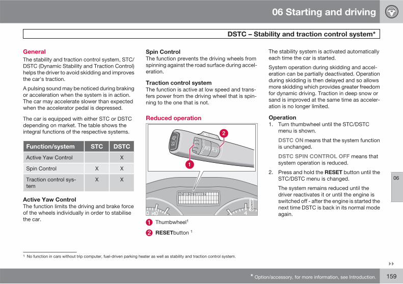
06 Starting and driving
DSTC – Stability and traction control system*
06
��
* Option/accessory, for more information, see Introduction. 159
General
The stability and traction control system, STC/DSTC (Dynamic Stability and Traction Control)helps the driver to avoid skidding and improvesthe car's traction.
A pulsing sound may be noticed during brakingor acceleration when the system is in action.The car may accelerate slower than expectedwhen the accelerator pedal is depressed.
The car is equipped with either STC or DSTCdepending on market. The table shows theintegral functions of the respective systems.
Function/system STC DSTC
Active Yaw Control X
Spin Control X X
Traction control sys-tem
X X
Active Yaw Control
The function limits the driving and brake forceof the wheels individually in order to stabilisethe car.
Spin Control
The function prevents the driving wheels fromspinning against the road surface during accel-eration.
Traction control system
The function is active at low speed and trans-fers power from the driving wheel that is spin-ning to the one that is not.
Reduced operation
G029057
Thumbwheel1
RESETbutton 1
The stability system is activated automaticallyeach time the car is started.
System operation during skidding and accel-eration can be partially deactivated. Operationduring skidding is then delayed and so allowsmore skidding which provides greater freedomfor dynamic driving. Traction in deep snow orsand is improved at the same time as acceler-ation is no longer limited.
Operation
1. Turn thumbwheel until the STC/DSTCmenu is shown.
DSTC ON means that the system functionis unchanged.
DSTC SPIN CONTROL OFF means thatsystem operation is reduced.
2. Press and hold the RESET button until theSTC/DSTC menu is changed.
The system remains reduced until thedriver reactivates it or until the engine isswitched off - after the engine is started thenext time DSTC is back in its normal modeagain.
1 No function in cars without trip computer, fuel-driven parking heater as well as stability and traction control system.
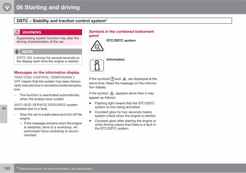
06 Starting and driving
DSTC – Stability and traction control system*
06
160 * Option/accessory, for more information, see Introduction.
WARNING
Suppressing system function may alter thedriving characteristics of the car.
NOTE
DSTC ON is shown for several seconds onthe display each time the engine is started.
Messages on the information display
TRACTION CONTROL TEMPORARILY
OFF means that the system has been tempo-rarily reduced due to excessive brake tempera-ture.
� The function is reactivated automaticallywhen the brakes have cooled.
ANTI-SKID SERVICE REQUIRED systemdisabled due to a fault.
� Stop the car in a safe place and turn off theengine.> If the message remains when the engine
is restarted, drive to a workshop. Anauthorised Volvo workshop is recom-mended.
Symbols in the combined instrumentpanel
STC/DSTC system
Information
If the symbols and are displayed at thesame time: Read the message on the informa-tion display.
If the symbol appears alone then it mayappear as follows:
• Flashing light means that the STC/DSTCsystem is now being activated.
• Constant glow for two seconds meanssystem check when the engine is started.
• Constant glow after starting the engine orwhile driving means that there is a fault inthe STC/DSTC system.
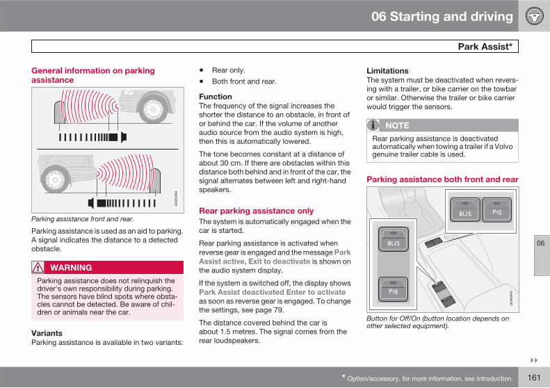
06 Starting and driving
Park Assist*
06
��
* Option/accessory, for more information, see Introduction. 161
General information on parkingassistance
Parking assistance front and rear.
Parking assistance is used as an aid to parking.A signal indicates the distance to a detectedobstacle.
WARNING
Parking assistance does not relinquish thedriver's own responsibility during parking.The sensors have blind spots where obsta-cles cannot be detected. Be aware of chil-dren or animals near the car.
Variants
Parking assistance is available in two variants:
• Rear only.
• Both front and rear.
Function
The frequency of the signal increases theshorter the distance to an obstacle, in front ofor behind the car. If the volume of anotheraudio source from the audio system is high,then this is automatically lowered.
The tone becomes constant at a distance ofabout 30 cm. If there are obstacles within thisdistance both behind and in front of the car, thesignal alternates between left and right-handspeakers.
Rear parking assistance only
The system is automatically engaged when thecar is started.
Rear parking assistance is activated whenreverse gear is engaged and the message Park
Assist active, Exit to deactivate is shown onthe audio system display.
If the system is switched off, the display showsPark Assist deactivated Enter to activate
as soon as reverse gear is engaged. To changethe settings, see page 79.
The distance covered behind the car isabout 1.5 metres. The signal comes from therear loudspeakers.
Limitations
The system must be deactivated when revers-ing with a trailer, or bike carrier on the towbaror similar. Otherwise the trailer or bike carrierwould trigger the sensors.
NOTE
Rear parking assistance is deactivatedautomatically when towing a trailer if a Volvogenuine trailer cable is used.
Parking assistance both front and rear
Button for Off/On (button location depends onother selected equipment).
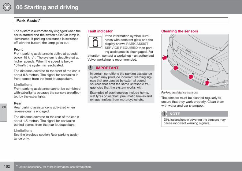
06 Starting and driving
Park Assist*
06
162 * Option/accessory, for more information, see Introduction.
The system is automatically engaged when thecar is started and the switch's On/Off lamp isilluminated. If parking assistance is switchedoff with the button, the lamp goes out.
Front
Front parking assistance is active at speedsbelow 15 km/h. The system is deactivated athigher speeds. When the speed is below10 km/h the system is reactivated.
The distance covered to the front of the car isabout 0.8 metres. The signal for obstacles infront comes from the front loudspeakers.
Limitations
Front parking assistance cannot be combinedwith extra lights because the sensors are affec-ted by the extra lights.
Rear
Rear parking assistance is activated whenreverse gear is engaged.
The distance covered to the rear of the car isabout 1.5 metres. The signal for obstaclesbehind comes from the rear loudspeakers.
Limitations
See the previous section Rear parking assis-tance only.
Fault indicator
If the information symbol illumi-nates with constant glow and thedisplay shows PARK ASSIST
SERVICE REQUIRED then park-ing assistance is disengaged. For
attention, contact a workshop - an authorisedVolvo workshop is recommended.
IMPORTANT
In certain conditions the parking assistancesystem may produce incorrect warning sig-nals that are caused by external soundsources that emit the same ultrasonic fre-quencies that the system works with.
Examples of such sources include horns,wet tyres on asphalt, pneumatic brakes andexhaust noises from motorcycles etc.
Cleaning the sensors
Parking assistance sensors.
The sensors must be cleaned regularly toensure that they work properly. Clean themwith water and car shampoo.
NOTE
Dirt, ice and snow covering the sensors maycause incorrect warning signals.
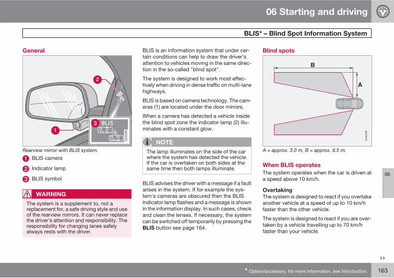
06 Starting and driving
BLIS* – Blind Spot Information System
06
��
* Option/accessory, for more information, see Introduction. 163
General
G020295
Rearview mirror with BLIS system.
BLIS camera
Indicator lamp
BLIS symbol
WARNING
The system is a supplement to, not areplacement for, a safe driving style and useof the rearview mirrors. It can never replacethe driver's attention and responsibility. Theresponsibility for changing lanes safelyalways rests with the driver.
BLIS is an information system that under cer-tain conditions can help to draw the driver'sattention to vehicles moving in the same direc-tion in the so-called "blind spot".
The system is designed to work most effec-tively when driving in dense traffic on multi-lanehighways.
BLIS is based on camera technology. The cam-eras (1) are located under the door mirrors.
When a camera has detected a vehicle insidethe blind spot zone the indicator lamp (2) illu-minates with a constant glow.
NOTE
The lamp illuminates on the side of the carwhere the system has detected the vehicle.If the car is overtaken on both sides at thesame time then both lamps illuminate.
BLIS advises the driver with a message if a faultarises in the system. If for example the sys-tem's cameras are obscured then the BLISindicator lamp flashes and a message is shownin the information display. In such cases, checkand clean the lenses. If necessary, the systemcan be switched off temporarily by pressing theBLIS button see page 164.
Blind spots
A = approx. 3.0 m, B = approx. 9.5 m.
When BLIS operates
The system operates when the car is driven ata speed above 10 km/h.
Overtaking
The system is designed to react if you overtakeanother vehicle at a speed of up to 10 km/hfaster than the other vehicle.
The system is designed to react if you are over-taken by a vehicle travelling up to 70 km/hfaster than your vehicle.
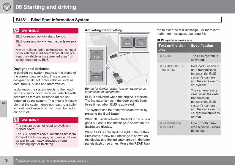
06 Starting and driving
BLIS* – Blind Spot Information System
06
164 * Option/accessory, for more information, see Introduction.
WARNING
BLIS does not work in sharp bends.
BLIS does not work when the car is revers-ing.
A wide trailer coupled to the car can concealother vehicles in adjacent lanes. It can pre-vent the vehicle in the screened area frombeing detected by BLIS.
Daylight and darkness
In daylight the system reacts to the shape ofthe surrounding vehicles. The system isdesigned to detect motor vehicles such ascars, trucks, buses and motorcycles.
In darkness the system reacts to the head-lamps of surrounding vehicles. Vehicles withheadlamps that are switched off are notdetected by the system. This means for exam-ple that the system does not react to a trailerwithout headlamps which is towed behind acar or truck.
WARNING
The system does not react to cyclists ormoped riders.
The BLIS cameras have limitations similar tothose of the human eye, i.e. they do not seeas well in e.g. heavy snowfall, strongoncoming light or thick fog.
Activating/deactivating
Button for Off/On (button location depends onother selected equipment).
BLIS is activated when the engine is started.The indicator lamps in the door panels flashthree times when BLIS is activated.
The system can be deactivated/activated bypressing the BLIS button.
When BLIS is deactivated the light in the buttongoes out and a text message is shown on thedashboard display.
When BLIS is activated the light in the buttonilluminates, a new text message is shown onthe display and the indicator lamps in the doorpanels flash three times. Press the READ but-
ton to clear the text message. For more infor-mation on messages, see page 54.
BLIS system message
Text on the dis-play
Specification
BLIS ON The BLIS system isactivated.
BLIS REDUCED
FUNCTION
Reduced function indata transmissionbetween the BLISsystem's cameraand the car's electri-cal system.
The camera resetsitself when the datatransmissionbetween the BLISsystem's cameraand the car's electri-cal system returns tonormal.
BLIS CAMERA
BLOCKED
One or both cam-eras blocked - cleanthe lenses.
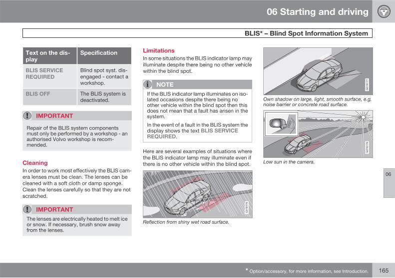
06 Starting and driving
BLIS* – Blind Spot Information System
06
* Option/accessory, for more information, see Introduction. 165
Text on the dis-play
Specification
BLIS SERVICE
REQUIRED
Blind spot syst. dis-engaged - contact aworkshop.
BLIS OFF The BLIS system isdeactivated.
IMPORTANT
Repair of the BLIS system componentsmust only be performed by a workshop - anauthorised Volvo workshop is recom-mended.
Cleaning
In order to work most effectively the BLIS cam-era lenses must be clean. The lenses can becleaned with a soft cloth or damp sponge.Clean the lenses carefully so that they are notscratched.
IMPORTANT
The lenses are electrically heated to melt iceor snow. If necessary, brush snow awayfrom the lenses.
Limitations
In some situations the BLIS indicator lamp mayilluminate despite there being no other vehiclewithin the blind spot.
NOTE
If the BLIS indicator lamp illuminates on iso-lated occasions despite there being noother vehicle within the blind spot then thisdoes not mean that a fault has arisen in thesystem.
In the event of a fault in the BLIS system thedisplay shows the text BLIS SERVICEREQUIRED.
Here are several examples of situations wherethe BLIS indicator lamp may illuminate even ifthere is no other vehicle within the blind spot.
Reflection from shiny wet road surface.
G018177
Own shadow on large, light, smooth surface, e.g.noise barrier or concrete road surface.
Low sun in the camera.
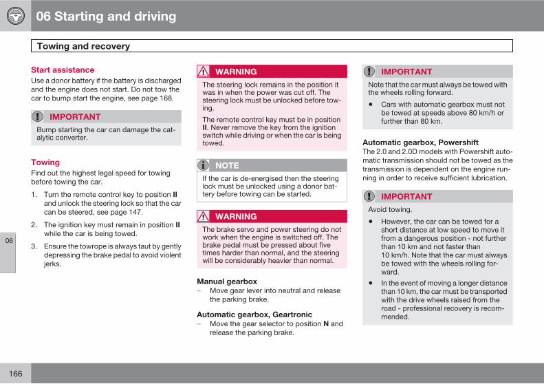
06 Starting and driving
Towing and recovery
06
166
Start assistance
Use a donor battery if the battery is dischargedand the engine does not start. Do not tow thecar to bump start the engine, see page 168.
IMPORTANT
Bump starting the car can damage the cat-alytic converter.
Towing
Find out the highest legal speed for towingbefore towing the car.
1. Turn the remote control key to position IIand unlock the steering lock so that the carcan be steered, see page 147.
2. The ignition key must remain in position IIwhile the car is being towed.
3. Ensure the towrope is always taut by gentlydepressing the brake pedal to avoid violentjerks.
WARNING
The steering lock remains in the position itwas in when the power was cut off. Thesteering lock must be unlocked before tow-ing.
The remote control key must be in positionII. Never remove the key from the ignitionswitch while driving or when the car is beingtowed.
NOTE
If the car is de-energised then the steeringlock must be unlocked using a donor bat-tery before towing can be started.
WARNING
The brake servo and power steering do notwork when the engine is switched off. Thebrake pedal must be pressed about fivetimes harder than normal, and the steeringwill be considerably heavier than normal.
Manual gearbox
� Move gear lever into neutral and releasethe parking brake.
Automatic gearbox, Geartronic
� Move the gear selector to position N andrelease the parking brake.
IMPORTANT
Note that the car must always be towed withthe wheels rolling forward.
• Cars with automatic gearbox must notbe towed at speeds above 80 km/h orfurther than 80 km.
Automatic gearbox, Powershift
The 2.0 and 2.0D models with Powershift auto-matic transmission should not be towed as thetransmission is dependent on the engine run-ning in order to receive sufficient lubrication.
IMPORTANT
Avoid towing.
• However, the car can be towed for ashort distance at low speed to move itfrom a dangerous position - not furtherthan 10 km and not faster than10 km/h. Note that the car must alwaysbe towed with the wheels rolling for-ward.
• In the event of moving a longer distancethan 10 km, the car must be transportedwith the drive wheels raised from theroad - professional recovery is recom-mended.
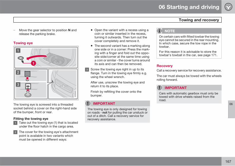
06 Starting and driving
Towing and recovery
06
167
� Move the gear selector to position N andrelease the parking brake.
Towing eye
The towing eye is screwed into a threadedsocket behind a cover on the right-hand sideof the bumper, front or rear.
Fitting the towing eye
Take out the towing eye (1) that is locatedunder the floor hatch in the cargo area.
The cover for the towing eye's attachmentpoint is available in two variants whichmust be opened in different ways:
• Open the variant with a recess using acoin or similar inserted in the recess,turning it outwards. Then turn out thecover completely and remove it.
• The second variant has a marking alongone side or in a corner: Press the mark-ing with a finger and fold out the oppo-site side/corner at the same time usinga coin or similar - the cover turns aroundits axis and can then be removed.
Screw the towing eye right in up to itsflange. Turn in the towing eye firmly e.g.using the wheel wrench.
After use, unscrew the towing eye andreturn it to its place.
Finish by refitting the cover onto thebumper.
IMPORTANT
The towing eye is only designed for towingon roads - not for pulling the car unstuck orout of a ditch. Call a recovery service forrecovery assistance.
NOTE
On certain cars with fitted towbar the towingeye cannot be secured in the rear mounting.In which case, secure the tow rope in thetowbar.
For this reason it is advisable to store thetowbar's towball in the car, see page 171.
Recovery
Call a recovery service for recovery assistance.
The car must always be towed with the wheelsrolling forward.
IMPORTANT
Cars with automatic gearbox must only betowed with drive wheels raised from theroad.
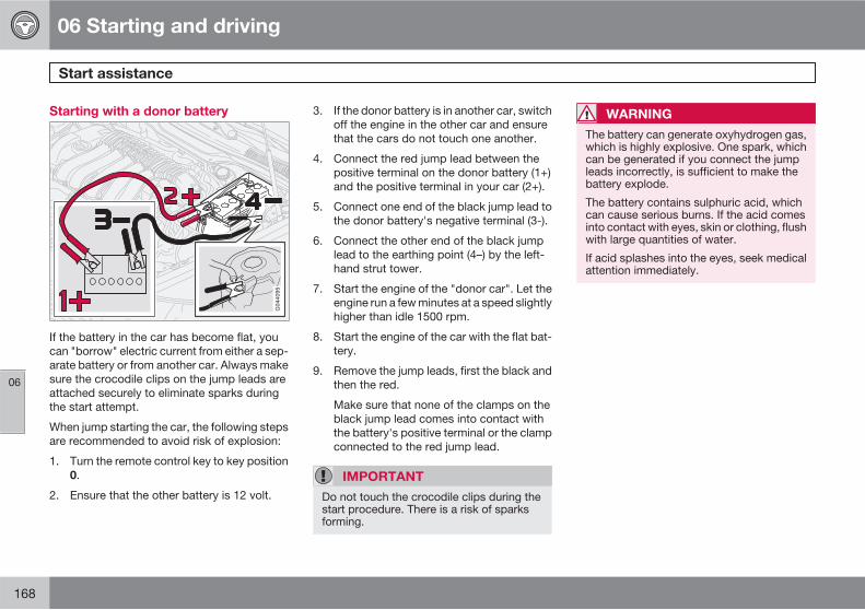
06 Starting and driving
Start assistance
06
168
Starting with a donor battery
If the battery in the car has become flat, youcan "borrow" electric current from either a sep-arate battery or from another car. Always makesure the crocodile clips on the jump leads areattached securely to eliminate sparks duringthe start attempt.
When jump starting the car, the following stepsare recommended to avoid risk of explosion:
1. Turn the remote control key to key position0.
2. Ensure that the other battery is 12 volt.
3. If the donor battery is in another car, switchoff the engine in the other car and ensurethat the cars do not touch one another.
4. Connect the red jump lead between thepositive terminal on the donor battery (1+)and the positive terminal in your car (2+).
5. Connect one end of the black jump lead tothe donor battery's negative terminal (3-).
6. Connect the other end of the black jumplead to the earthing point (4–) by the left-hand strut tower.
7. Start the engine of the "donor car". Let theengine run a few minutes at a speed slightlyhigher than idle 1500 rpm.
8. Start the engine of the car with the flat bat-tery.
9. Remove the jump leads, first the black andthen the red.
Make sure that none of the clamps on theblack jump lead comes into contact withthe battery's positive terminal or the clampconnected to the red jump lead.
IMPORTANT
Do not touch the crocodile clips during thestart procedure. There is a risk of sparksforming.
WARNING
The battery can generate oxyhydrogen gas,which is highly explosive. One spark, whichcan be generated if you connect the jumpleads incorrectly, is sufficient to make thebattery explode.
The battery contains sulphuric acid, whichcan cause serious burns. If the acid comesinto contact with eyes, skin or clothing, flushwith large quantities of water.
If acid splashes into the eyes, seek medicalattention immediately.
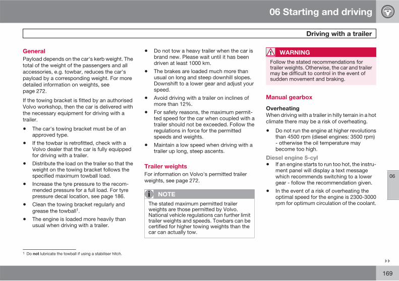
06 Starting and driving
Driving with a trailer
06
��
169
General
Payload depends on the car's kerb weight. Thetotal of the weight of the passengers and allaccessories, e.g. towbar, reduces the car'spayload by a corresponding weight. For moredetailed information on weights, seepage 272.
If the towing bracket is fitted by an authorisedVolvo workshop, then the car is delivered withthe necessary equipment for driving with atrailer.
• The car's towing bracket must be of anapproved type.
• If the towbar is retrofitted, check with aVolvo dealer that the car is fully equippedfor driving with a trailer.
• Distribute the load on the trailer so that theweight on the towing bracket follows thespecified maximum towball load.
• Increase the tyre pressure to the recom-mended pressure for a full load. For tyrepressure decal location, see page 186.
• Clean the towing bracket regularly andgrease the towball1.
• The engine is loaded more heavily thanusual when driving with a trailer.
• Do not tow a heavy trailer when the car isbrand new. Please wait until it has beendriven at least 1000 km.
• The brakes are loaded much more thanusual on long and steep downhill slopes.Downshift to a lower gear and adjust yourspeed.
• Avoid driving with a trailer on inclines ofmore than 12%.
• For safety reasons, the maximum permit-ted speed for the car when coupled with atrailer should not be exceeded. Follow theregulations in force for the permittedspeeds and weights.
• Maintain a low speed when driving with atrailer up long, steep ascents.
Trailer weights
For information on Volvo's permitted trailerweights, see page 272.
NOTE
The stated maximum permitted trailerweights are those permitted by Volvo.National vehicle regulations can further limittrailer weights and speeds. Towbars can becertified for higher towing weights than thecar can actually tow.
WARNING
Follow the stated recommendations fortrailer weights. Otherwise, the car and trailermay be difficult to control in the event ofsudden movement and braking.
Manual gearbox
Overheating
When driving with a trailer in hilly terrain in a hotclimate there may be a risk of overheating.
• Do not run the engine at higher revolutionsthan 4500 rpm (diesel engines: 3500 rpm)- otherwise the oil temperature maybecome too high.
Diesel engine 5-cyl
• If an engine starts to run too hot, the instru-ment panel will display a text messagewhich recommends switching to a lowergear - follow the recommendation given.
• In the event of a risk of overheating theoptimal speed for the engine is 2300-3000rpm for optimum circulation of the coolant.
1 Do not lubricate the towball if using a stabiliser hitch.
06 Starting and driving
Driving with a trailer
06
170
Automatic gearbox
Overheating
When driving with a trailer in hilly terrain in a hotclimate there may be a risk of overheating.
• An automatic gearbox selects the optimumgear related to load and engine speed.
Steep inclines
• Do not lock the automatic transmission ina higher gear than the engine "can copewith" - it is not always a good idea to driveat a high gear with low engine revolutions.
IMPORTANT
See also the specific information on slowdriving with trailer for cars with thePowershift automatic transmission on page155.
Parking on a hill
1. Depress the foot brake.
2. Apply the parking brake.
3. Move the gear selector to parking positionP.
4. Release the foot brake.
• Move the gear selector to park position Pwhen parking an automatic car with a
hitched trailer. Always use the parkingbrake.
• Block the wheels with chocks when park-ing a car with hitched trailer on a hill.
Starting on a hill
1. Depress the foot brake.
2. Move the gear selector to driving posi-tion D.
3. Release the parking brake.
4. Release the foot brake and start driving off.
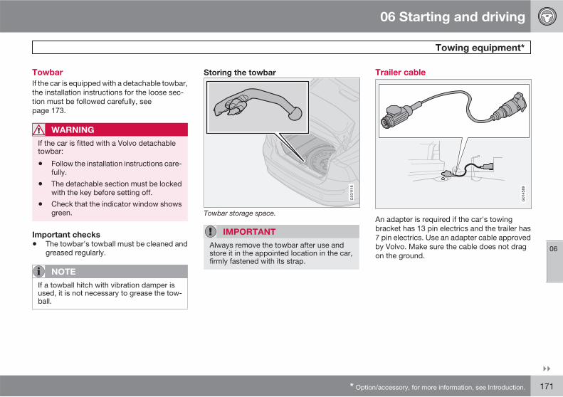
06 Starting and driving
Towing equipment*
06
��
* Option/accessory, for more information, see Introduction. 171
Towbar
If the car is equipped with a detachable towbar,the installation instructions for the loose sec-tion must be followed carefully, seepage 173.
WARNING
If the car is fitted with a Volvo detachabletowbar:
• Follow the installation instructions care-fully.
• The detachable section must be lockedwith the key before setting off.
• Check that the indicator window showsgreen.
Important checks
• The towbar's towball must be cleaned andgreased regularly.
NOTE
If a towball hitch with vibration damper isused, it is not necessary to grease the tow-ball.
Storing the towbar
G031116
Towbar storage space.
IMPORTANT
Always remove the towbar after use andstore it in the appointed location in the car,firmly fastened with its strap.
Trailer cable
G014589
An adapter is required if the car's towingbracket has 13 pin electrics and the trailer has7 pin electrics. Use an adapter cable approvedby Volvo. Make sure the cable does not dragon the ground.
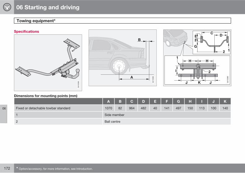
06 Starting and driving
Towing equipment*
06
172 * Option/accessory, for more information, see Introduction.
Specifications
G010393 G010384
G010385
Dimensions for mounting points (mm)
A B C D E F G H I J K
Fixed or detachable towbar standard 1070 82 964 482 40 141 497 150 113 100 140
1 Side member
2 Ball centre
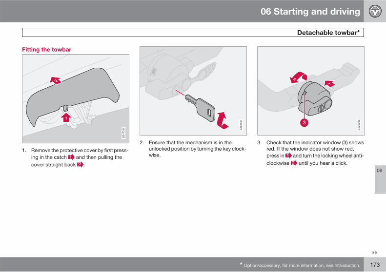
06 Starting and driving
Detachable towbar*
06
��
* Option/accessory, for more information, see Introduction. 173
Fitting the towbar
G017317
1. Remove the protective cover by first press-ing in the catch and then pulling thecover straight back .
G020301
2. Ensure that the mechanism is in theunlocked position by turning the key clock-wise.
G020302
3. Check that the indicator window (3) showsred. If the window does not show red,press in and turn the locking wheel anti-clockwise until you hear a click.
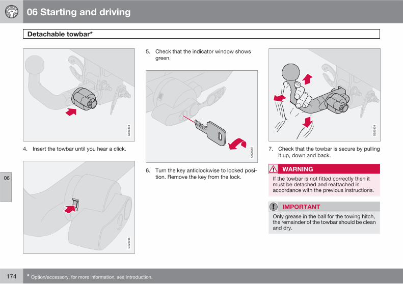
06 Starting and driving
Detachable towbar*
06
174 * Option/accessory, for more information, see Introduction.
G020304
4. Insert the towbar until you hear a click.
G020306
5. Check that the indicator window showsgreen.
G020307
6. Turn the key anticlockwise to locked posi-tion. Remove the key from the lock.
G020309
7. Check that the towbar is secure by pullingit up, down and back.
WARNING
If the towbar is not fitted correctly then itmust be detached and reattached inaccordance with the previous instructions.
IMPORTANT
Only grease in the ball for the towing hitch,the remainder of the towbar should be cleanand dry.
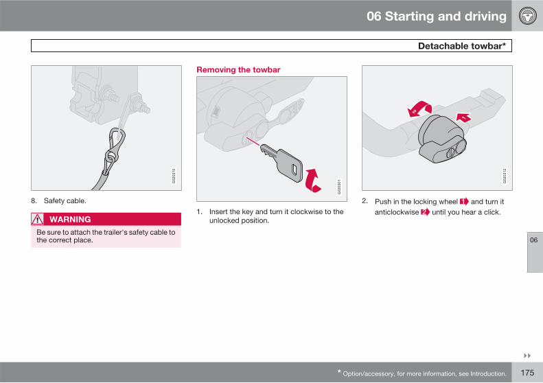
06 Starting and driving
Detachable towbar*
06
��
* Option/accessory, for more information, see Introduction. 175
G020310
8. Safety cable.
WARNING
Be sure to attach the trailer's safety cable tothe correct place.
Removing the towbar
G020301
1. Insert the key and turn it clockwise to theunlocked position.
G020312
2. Push in the locking wheel and turn itanticlockwise until you hear a click.
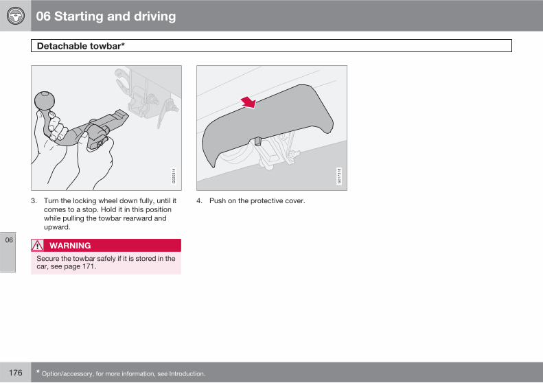
06 Starting and driving
Detachable towbar*
06
176 * Option/accessory, for more information, see Introduction.
G020314
3. Turn the locking wheel down fully, until itcomes to a stop. Hold it in this positionwhile pulling the towbar rearward andupward.
WARNING
Secure the towbar safely if it is stored in thecar, see page 171.
G017318
4. Push on the protective cover.
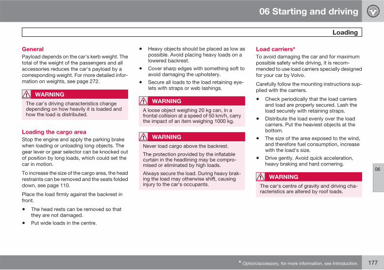
06 Starting and driving
Loading
06
* Option/accessory, for more information, see Introduction. 177
General
Payload depends on the car's kerb weight. Thetotal of the weight of the passengers and allaccessories reduces the car's payload by acorresponding weight. For more detailed infor-mation on weights, see page 272.
WARNING
The car's driving characteristics changedepending on how heavily it is loaded andhow the load is distributed.
Loading the cargo area
Stop the engine and apply the parking brakewhen loading or unloading long objects. Thegear lever or gear selector can be knocked outof position by long loads, which could set thecar in motion.
To increase the size of the cargo area, the headrestraints can be removed and the seats foldeddown, see page 110.
Place the load firmly against the backrest infront.
• The head rests can be removed so thatthey are not damaged.
• Put wide loads in the centre.
• Heavy objects should be placed as low aspossible. Avoid placing heavy loads on alowered backrest.
• Cover sharp edges with something soft toavoid damaging the upholstery.
• Secure all loads to the load retaining eye-lets with straps or web lashings.
WARNING
A loose object weighing 20 kg can, in afrontal collision at a speed of 50 km/h, carrythe impact of an item weighing 1000 kg.
WARNING
Never load cargo above the backrest.
The protection provided by the inflatablecurtain in the headlining may be compro-mised or eliminated by high loads.
Always secure the load. During heavy brak-ing the load may otherwise shift, causinginjury to the car's occupants.
Load carriers*
To avoid damaging the car and for maximumpossible safety while driving, it is recom-mended to use load carriers specially designedfor your car by Volvo.
Carefully follow the mounting instructions sup-plied with the carriers.
• Check periodically that the load carriersand load are properly secured. Lash theload securely with retaining straps.
• Distribute the load evenly over the loadcarriers. Put the heaviest objects at thebottom.
• The size of the area exposed to the wind,and therefore fuel consumption, increasewith the load's size.
• Drive gently. Avoid quick acceleration,heavy braking and hard cornering.
WARNING
The car's centre of gravity and driving cha-racteristics are altered by roof loads.
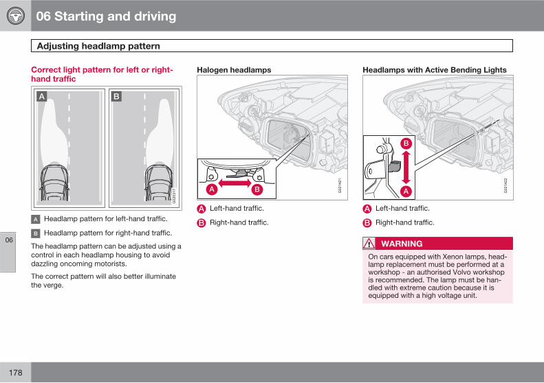
06 Starting and driving
Adjusting headlamp pattern
06
178
Correct light pattern for left or right-hand traffic
G020317
Headlamp pattern for left-hand traffic.
Headlamp pattern for right-hand traffic.
The headlamp pattern can be adjusted using acontrol in each headlamp housing to avoiddazzling oncoming motorists.
The correct pattern will also better illuminatethe verge.
Halogen headlamps
G021421
Left-hand traffic.
Right-hand traffic.
Headlamps with Active Bending Lights
G021422
Left-hand traffic.
Right-hand traffic.
WARNING
On cars equipped with Xenon lamps, head-lamp replacement must be performed at aworkshop - an authorised Volvo workshopis recommended. The lamp must be han-dled with extreme caution because it isequipped with a high voltage unit.
06 Starting and driving
06
179
180 * Option/accessory, for more information, see Introduction.
General.................................................................................................. 182Tyre pressure........................................................................................ 186Warning triangle* and spare wheel * .................................................... 189Changing wheels................................................................................... 192Emergency puncture repair* ................................................................ 194
WHEELS AND TYRES
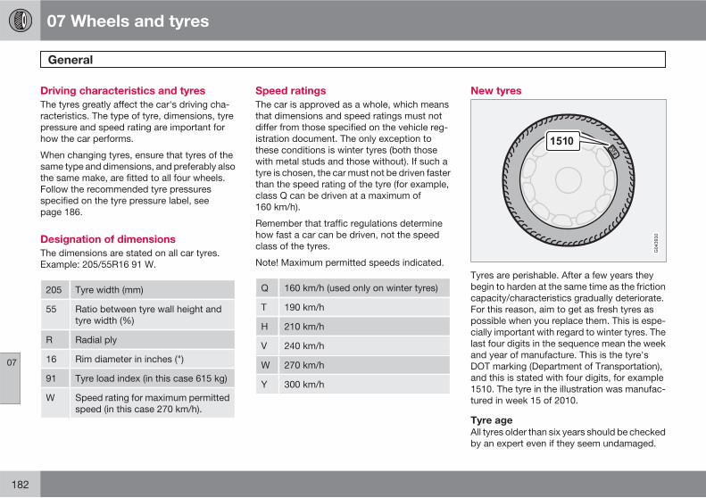
07 Wheels and tyres
General
07
182
Driving characteristics and tyres
The tyres greatly affect the car's driving cha-racteristics. The type of tyre, dimensions, tyrepressure and speed rating are important forhow the car performs.
When changing tyres, ensure that tyres of thesame type and dimensions, and preferably alsothe same make, are fitted to all four wheels.Follow the recommended tyre pressuresspecified on the tyre pressure label, seepage 186.
Designation of dimensions
The dimensions are stated on all car tyres.Example: 205/55R16 91 W.
205 Tyre width (mm)
55 Ratio between tyre wall height andtyre width (%)
R Radial ply
16 Rim diameter in inches (")
91 Tyre load index (in this case 615 kg)
W Speed rating for maximum permittedspeed (in this case 270 km/h).
Speed ratings
The car is approved as a whole, which meansthat dimensions and speed ratings must notdiffer from those specified on the vehicle reg-istration document. The only exception tothese conditions is winter tyres (both thosewith metal studs and those without). If such atyre is chosen, the car must not be driven fasterthan the speed rating of the tyre (for example,class Q can be driven at a maximum of160 km/h).
Remember that traffic regulations determinehow fast a car can be driven, not the speedclass of the tyres.
Note! Maximum permitted speeds indicated.
Q 160 km/h (used only on winter tyres)
T 190 km/h
H 210 km/h
V 240 km/h
W 270 km/h
Y 300 km/h
New tyres
Tyres are perishable. After a few years theybegin to harden at the same time as the frictioncapacity/characteristics gradually deteriorate.For this reason, aim to get as fresh tyres aspossible when you replace them. This is espe-cially important with regard to winter tyres. Thelast four digits in the sequence mean the weekand year of manufacture. This is the tyre'sDOT marking (Department of Transportation),and this is stated with four digits, for example1510. The tyre in the illustration was manufac-tured in week 15 of 2010.
Tyre age
All tyres older than six years should be checkedby an expert even if they seem undamaged.
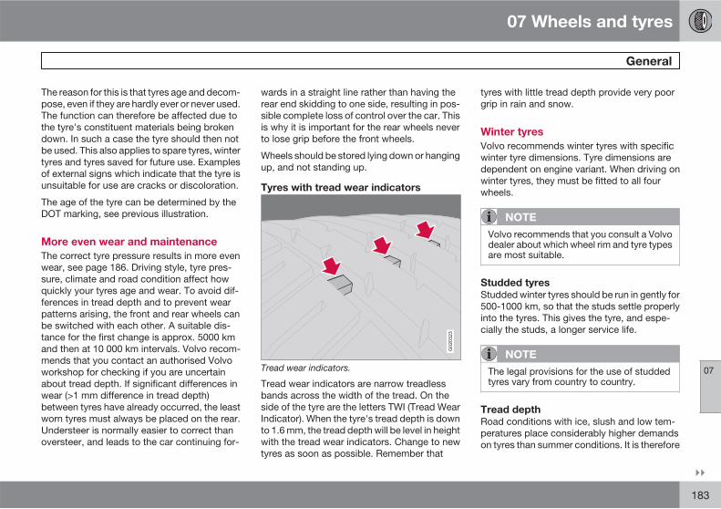
07 Wheels and tyres
General
07
��
183
The reason for this is that tyres age and decom-pose, even if they are hardly ever or never used.The function can therefore be affected due tothe tyre's constituent materials being brokendown. In such a case the tyre should then notbe used. This also applies to spare tyres, wintertyres and tyres saved for future use. Examplesof external signs which indicate that the tyre isunsuitable for use are cracks or discoloration.
The age of the tyre can be determined by theDOT marking, see previous illustration.
More even wear and maintenance
The correct tyre pressure results in more evenwear, see page 186. Driving style, tyre pres-sure, climate and road condition affect howquickly your tyres age and wear. To avoid dif-ferences in tread depth and to prevent wearpatterns arising, the front and rear wheels canbe switched with each other. A suitable dis-tance for the first change is approx. 5000 kmand then at 10 000 km intervals. Volvo recom-mends that you contact an authorised Volvoworkshop for checking if you are uncertainabout tread depth. If significant differences inwear (>1 mm difference in tread depth)between tyres have already occurred, the leastworn tyres must always be placed on the rear.Understeer is normally easier to correct thanoversteer, and leads to the car continuing for-
wards in a straight line rather than having therear end skidding to one side, resulting in pos-sible complete loss of control over the car. Thisis why it is important for the rear wheels neverto lose grip before the front wheels.
Wheels should be stored lying down or hangingup, and not standing up.
Tyres with tread wear indicators
G020323
Tread wear indicators.
Tread wear indicators are narrow treadlessbands across the width of the tread. On theside of the tyre are the letters TWI (Tread WearIndicator). When the tyre's tread depth is downto 1.6 mm, the tread depth will be level in heightwith the tread wear indicators. Change to newtyres as soon as possible. Remember that
tyres with little tread depth provide very poorgrip in rain and snow.
Winter tyres
Volvo recommends winter tyres with specificwinter tyre dimensions. Tyre dimensions aredependent on engine variant. When driving onwinter tyres, they must be fitted to all fourwheels.
NOTE
Volvo recommends that you consult a Volvodealer about which wheel rim and tyre typesare most suitable.
Studded tyres
Studded winter tyres should be run in gently for500-1000 km, so that the studs settle properlyinto the tyres. This gives the tyre, and espe-cially the studs, a longer service life.
NOTE
The legal provisions for the use of studdedtyres vary from country to country.
Tread depth
Road conditions with ice, slush and low tem-peratures place considerably higher demandson tyres than summer conditions. It is therefore
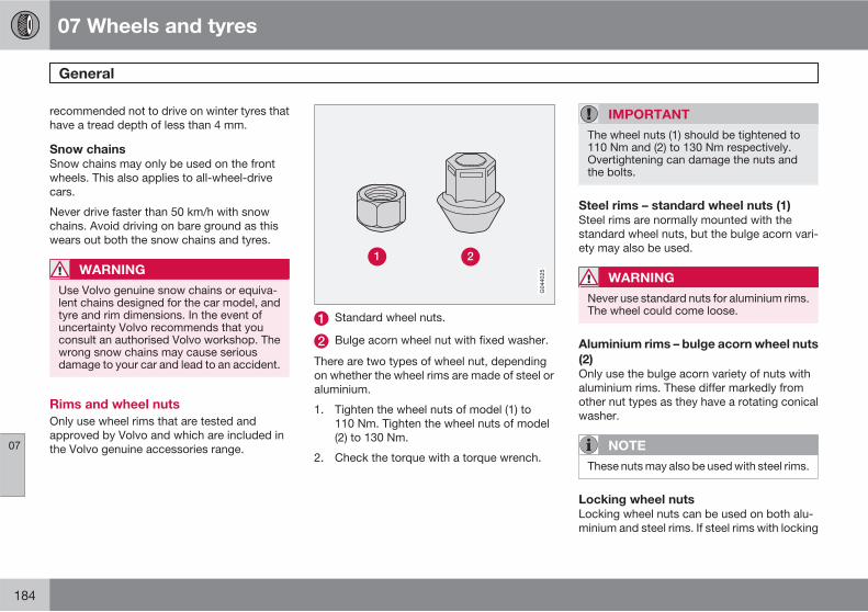
07 Wheels and tyres
General
07
184
recommended not to drive on winter tyres thathave a tread depth of less than 4 mm.
Snow chains
Snow chains may only be used on the frontwheels. This also applies to all-wheel-drivecars.
Never drive faster than 50 km/h with snowchains. Avoid driving on bare ground as thiswears out both the snow chains and tyres.
WARNING
Use Volvo genuine snow chains or equiva-lent chains designed for the car model, andtyre and rim dimensions. In the event ofuncertainty Volvo recommends that youconsult an authorised Volvo workshop. Thewrong snow chains may cause seriousdamage to your car and lead to an accident.
Rims and wheel nuts
Only use wheel rims that are tested andapproved by Volvo and which are included inthe Volvo genuine accessories range.
Standard wheel nuts.
Bulge acorn wheel nut with fixed washer.
There are two types of wheel nut, dependingon whether the wheel rims are made of steel oraluminium.
1. Tighten the wheel nuts of model (1) to110 Nm. Tighten the wheel nuts of model(2) to 130 Nm.
2. Check the torque with a torque wrench.
IMPORTANT
The wheel nuts (1) should be tightened to110 Nm and (2) to 130 Nm respectively.Overtightening can damage the nuts andthe bolts.
Steel rims – standard wheel nuts (1)
Steel rims are normally mounted with thestandard wheel nuts, but the bulge acorn vari-ety may also be used.
WARNING
Never use standard nuts for aluminium rims.The wheel could come loose.
Aluminium rims – bulge acorn wheel nuts
(2)
Only use the bulge acorn variety of nuts withaluminium rims. These differ markedly fromother nut types as they have a rotating conicalwasher.
NOTE
These nuts may also be used with steel rims.
Locking wheel nuts
Locking wheel nuts can be used on both alu-minium and steel rims. If steel rims with locking
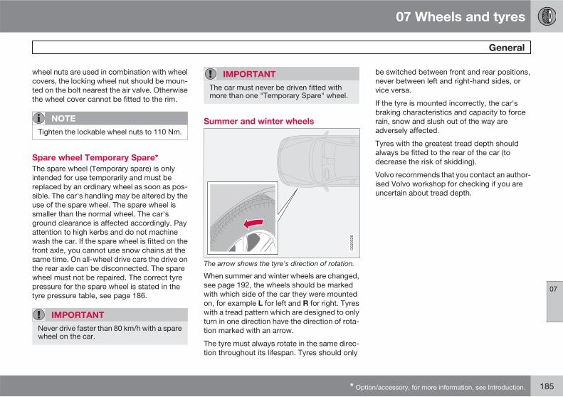
07 Wheels and tyres
General
07
* Option/accessory, for more information, see Introduction. 185
wheel nuts are used in combination with wheelcovers, the locking wheel nut should be moun-ted on the bolt nearest the air valve. Otherwisethe wheel cover cannot be fitted to the rim.
NOTE
Tighten the lockable wheel nuts to 110 Nm.
Spare wheel Temporary Spare*
The spare wheel (Temporary spare) is onlyintended for use temporarily and must bereplaced by an ordinary wheel as soon as pos-sible. The car's handling may be altered by theuse of the spare wheel. The spare wheel issmaller than the normal wheel. The car'sground clearance is affected accordingly. Payattention to high kerbs and do not machinewash the car. If the spare wheel is fitted on thefront axle, you cannot use snow chains at thesame time. On all-wheel drive cars the drive onthe rear axle can be disconnected. The sparewheel must not be repaired. The correct tyrepressure for the spare wheel is stated in thetyre pressure table, see page 186.
IMPORTANT
Never drive faster than 80 km/h with a sparewheel on the car.
IMPORTANT
The car must never be driven fitted withmore than one "Temporary Spare" wheel.
Summer and winter wheels
G020325
The arrow shows the tyre's direction of rotation.
When summer and winter wheels are changed,see page 192, the wheels should be markedwith which side of the car they were mountedon, for example L for left and R for right. Tyreswith a tread pattern which are designed to onlyturn in one direction have the direction of rota-tion marked with an arrow.
The tyre must always rotate in the same direc-tion throughout its lifespan. Tyres should only
be switched between front and rear positions,never between left and right-hand sides, orvice versa.
If the tyre is mounted incorrectly, the car'sbraking characteristics and capacity to forcerain, snow and slush out of the way areadversely affected.
Tyres with the greatest tread depth shouldalways be fitted to the rear of the car (todecrease the risk of skidding).
Volvo recommends that you contact an author-ised Volvo workshop for checking if you areuncertain about tread depth.
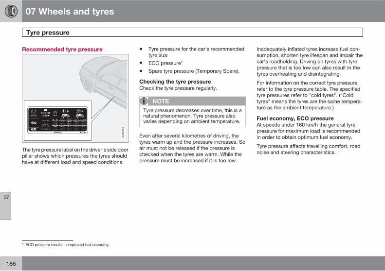
07 Wheels and tyres
Tyre pressure
07
186
Recommended tyre pressure
G020791
The tyre pressure label on the driver's side doorpillar shows which pressures the tyres shouldhave at different load and speed conditions.
• Tyre pressure for the car's recommendedtyre size
• ECO pressure1
• Spare tyre pressure (Temporary Spare).
Checking the tyre pressure
Check the tyre pressure regularly.
NOTE
Tyre pressure decreases over time, this is anatural phenomenon. Tyre pressure alsovaries depending on ambient temperature.
Even after several kilometres of driving, thetyres warm up and the pressure increases. Soair must not be released if the pressure ischecked when the tyres are warm. While thepressure must be increased if it is too low.
Inadequately inflated tyres increase fuel con-sumption, shorten tyre lifespan and impair thecar's roadholding. Driving on tyres with tyrepressure that is too low can also result in thetyres overheating and disintegrating.
For information on the correct tyre pressure,refer to the tyre pressure table. The specifiedtyre pressures refer to "cold tyres". ("Coldtyres" means the tyres are the same tempera-ture as the ambient temperature.)
Fuel economy, ECO pressure
At speeds under 160 km/h the general tyrepressure for maximum load is recommendedin order to obtain optimum fuel economy.
Tyre pressure affects travelling comfort, roadnoise and steering characteristics.
1 ECO pressure results in improved fuel economy.
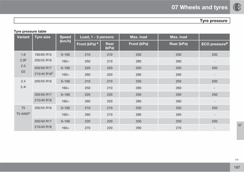
07 Wheels and tyres
Tyre pressure
07
��
187
Tyre pressure table
Variant Tyre size Speed(km/h)
Load, 1 - 3 persons Max. load Max. load
Front (kPa) A Rear(kPa)
Front (kPa) Rear (kPa) ECO pressureB
1.6
2.0F
2.0
D2
195/65 R15
205/55 R16
0–160 210 210 250 250 250
160+ 250 210 280 260 -
205/50 R17
215/45 R18C
0–160 220 220 250 250 250
160+ 260 220 280 260 -
2.4
2.4i
205/55 R16 0–160 210 210 250 250 250
160+ 250 210 280 260 -
205/50 R17
215/45 R18
0–160 220 220 250 250 250
160+ 260 220 280 260 -
T5
T5 AWDD
205/55 R16 0–160 210 210 250 250 250
160+ 260 210 280 260 -
205/50 R17
215/45 R18
0–160 220 220 250 250 250
160+ 270 220 290 270 -
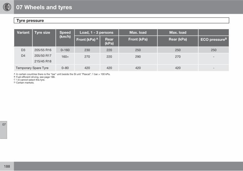
07 Wheels and tyres
Tyre pressure
07
188
Variant Tyre size Speed(km/h)
Load, 1 - 3 persons Max. load Max. load
Front (kPa) A Rear(kPa)
Front (kPa) Rear (kPa) ECO pressureB
D3
D4
205/55 R16
205/50 R17
215/45 R18
0–160 230 220 250 250 250
160+ 270 220 290 270 -
Temporary Spare Tyre 0–80 420 420 420 420 -
A In certain countries there is the "bar" unit beside the SI unit "Pascal": 1 bar = 100 kPa.B Fuel-efficient driving, see page 186.C 1.6 cannot select this tyre.D Certain markets.
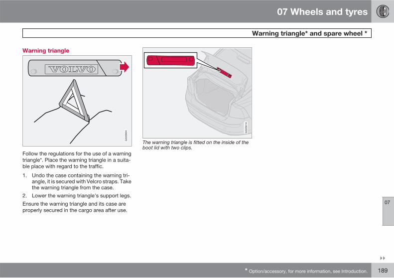
07 Wheels and tyres
Warning triangle* and spare wheel *
07
��
* Option/accessory, for more information, see Introduction. 189
Warning triangle
G020904
Follow the regulations for the use of a warningtriangle*. Place the warning triangle in a suita-ble place with regard to the traffic.
1. Undo the case containing the warning tri-angle, it is secured with Velcro straps. Takethe warning triangle from the case.
2. Lower the warning triangle's support legs.
Ensure the warning triangle and its case areproperly secured in the cargo area after use.
G020914
The warning triangle is fitted on the inside of theboot lid with two clips.
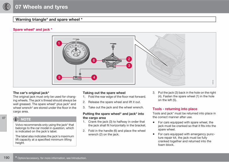
07 Wheels and tyres
Warning triangle* and spare wheel *
07
190 * Option/accessory, for more information, see Introduction.
Spare wheel* and jack *
G00
0000
The car's original jack*
The original jack must only be used for chang-ing wheels. The jack's thread should always bewell greased. The spare wheel* plus jack* andwheel wrench* are stored under the floor in thecargo area.
NOTE
Volvo recommends only using the jack* thatbelongs to the car model in question, whichis indicated on the jack's label.
The label also indicates the jack's maximumlift capacity at a specified minimum liftingheight.
Taking out the spare wheel
1. Fold the rear edge of the floor mat forward.
2. Release the spare wheel and lift it out.
3. Take out the jack and the wheel wrench.
Putting the spare wheel* and jack* into
the cargo area
1. Crank the jack (3) to halfway in order thatthe jack shall fit horizontally in the bracket.
2. Fold in the handle (6) and place the wheelwrench (2) on the jack.
3. Put the jack (3) back in the hole on the right(4). Fasten the spare wheel (1) in the holeon the left (5).
Tools - returning into place
Tools and jack* must be returned into place inthe correct manner after use.
• For cars equipped with spare wheel, thejack must be cranked so that it fits into thespare wheel.
• For cars equipped with emergency punc-ture repair kit, the jack must be fullycranked together and returned into thefoam block.
07 Wheels and tyres
Warning triangle* and spare wheel *
07
* Option/accessory, for more information, see Introduction. 191
IMPORTANT
The tools and jack* must be stored in theintended location in the car's cargo areawhen not in use.
First aid*
A case with first aid equipment is located in thecargo area.
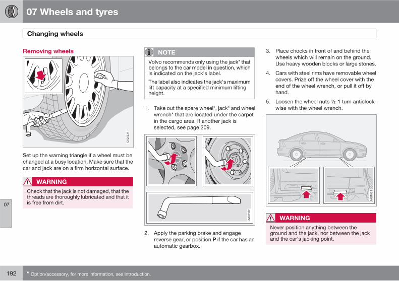
07 Wheels and tyres
Changing wheels
07
192 * Option/accessory, for more information, see Introduction.
Removing wheels
G020331
Set up the warning triangle if a wheel must bechanged at a busy location. Make sure that thecar and jack are on a firm horizontal surface.
WARNING
Check that the jack is not damaged, that thethreads are thoroughly lubricated and that itis free from dirt.
NOTE
Volvo recommends only using the jack* thatbelongs to the car model in question, whichis indicated on the jack's label.
The label also indicates the jack's maximumlift capacity at a specified minimum liftingheight.
1. Take out the spare wheel*, jack* and wheelwrench* that are located under the carpetin the cargo area. If another jack isselected, see page 209.
G020332
2. Apply the parking brake and engagereverse gear, or position P if the car has anautomatic gearbox.
3. Place chocks in front of and behind thewheels which will remain on the ground.Use heavy wooden blocks or large stones.
4. Cars with steel rims have removable wheelcovers. Prize off the wheel cover with theend of the wheel wrench, or pull it off byhand.
5. Loosen the wheel nuts ½-1 turn anticlock-wise with the wheel wrench.
WARNING
Never position anything between theground and the jack, nor between the jackand the car's jacking point.
07 Wheels and tyres
Changing wheels
07
193
6. There are two jacking points on each sideof the car. There is a recess in the plasticcover at each point. Crank the foot of thejack down so it is pressed squarely on theground. Check that the jack is seated cor-rectly in the intended jacking point, as illus-trated, and that the base is located directlyunder it.
IMPORTANT
The ground must be firm, smooth and level.
7. Lift the car so that the wheel is free.Remove the wheel nuts and lift off thewheel.
Fitting the wheel
1. Clean the contact surfaces between wheeland hub.
2. Put on the wheel. Tighten the wheel nuts.
3. Lower the car so that the wheel cannotrotate.
4. Tighten the wheel nuts crosswise. It isimportant that the wheel nuts are tightenedproperly. Tighten to 110 Nm.
Standard wheel nuts and domed wheelnuts with rotating washers (tightening tor-que: 110 Nm).
Domed wheel nuts with fixed washers(tightening torque: 130 Nm).
Check the torque with a torque wrench.
5. Put on the wheel cover (steel rim).
WARNING
Never crawl under the car when it is raisedon the jack.
Passengers must leave the car when it israised on the jack.
Ensure that passengers wait with the car -or preferably a crash barrier - between themand the road.
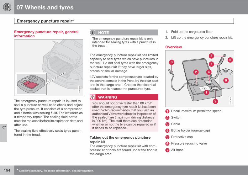
07 Wheels and tyres
Emergency puncture repair*
07
194 * Option/accessory, for more information, see Introduction.
Emergency puncture repair, generalinformation
The emergency puncture repair kit is used toseal a puncture as well as to check and adjustthe tyre pressure. It consists of a compressorand a bottle with sealing fluid. The kit works asa temporary repair. The sealing fluid bottlemust be replaced before its expiration date andafter use.
The sealing fluid effectively seals tyres punc-tured in the tread.
NOTE
The emergency puncture repair kit is onlyintended for sealing tyres with a puncture inthe tread.
The emergency puncture repair kit has limitedcapacity to seal tyres which have punctures inthe wall. Do not seal tyres with the emergencypuncture repair kit if they have larger slits,cracks or similar damage.
12V sockets for the compressor are located bythe centre console in the front, by the rear seatand in the cargo area*. Choose the electricalsocket that is nearest the punctured tyre.
WARNING
You should not drive faster than 80 km/hafter the emergency tyre repair kit has beenused. Volvo recommends that you visit anauthorised Volvo workshop for inspection ofthe sealed tyre (maximum driving distanceis 200 km). The staff there can determinewhether or not the tyre can be repaired or ifit needs to be replaced.
Taking out the emergency puncture
repair kit
The emergency puncture repair kit with com-pressor and tools are found under the floor inthe cargo area.
1. Fold up the cargo area floor.
2. Lift up the emergency puncture repair kit.
Overview
G020400
Decal, maximum permitted speed
Switch
Cable
Bottle holder (orange cap)
Protective cap
Pressure reducing valve
Air hose
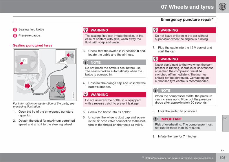
07 Wheels and tyres
Emergency puncture repair*
07
��
* Option/accessory, for more information, see Introduction. 195
Sealing fluid bottle
Pressure gauge
Sealing punctured tyres
G019723
For information on the function of the parts, seepreceding illustration.
1. Open the lid of the emergency puncturerepair kit.
2. Detach the decal for maximum permittedspeed and affix it to the steering wheel.
WARNING
The sealing fluid can irritate the skin. In thecase of contact with skin, wash away thefluid with soap and water.
3. Check that the switch is in position 0 andlocate the cable and the air hose.
NOTE
Do not break the bottle's seal before use.The seal is broken automatically when thebottle is screwed in.
4. Unscrew the orange cap and unscrew thebottle's stopper.
WARNING
Do not unscrew the bottle, it is equippedwith a reverse catch to prevent leakage.
5. Screw the bottle into its holder.
6. Unscrew the wheel's dust cap and screwin the air hose valve connection to the bot-tom of the thread on the tyre's air valve.
WARNING
Do not leave children in the car withoutsupervision when the engine is running.
7. Plug the cable into the 12 V socket andstart the car.
WARNING
Never stand next to the tyre when the com-pressor is running. If cracks or unevennessarise then the compressor must beswitched off immediately. The journeyshould not be continued. Contacting anauthorised tyre centre is recommended.
NOTE
When the compressor starts, the pressurecan increase up to 6 bar but the pressuredrops after approximately 30 seconds.
8. Flick the switch to position I.
IMPORTANT
Risk of overheating. The compressor mustnot run for more than 10 minutes.
9. Inflate the tyre for 7 minutes.
07 Wheels and tyres
Emergency puncture repair*
07
196 * Option/accessory, for more information, see Introduction.
WARNING
If the pressure is below 1.8 bar then the holein the tyre is too big. The journey should notbe continued. Contacting an authorised tyrecentre is recommended.
10. Switch off the compressor to check thepressure on the pressure gauge. Minimumpressure is 1.8 bar and maximum is3.5 bar.
11. Switch off the compressor and unplug thecable from the 12 V socket.
12. Detach the hose from the tyre valve and fitthe valve cap.
13. As soon as possible, drive approximately 3km at a maximum speed of 80 km/h so thatthe sealing fluid can seal the tyre.
Rechecking the repair and pressure
1. Reconnect the equipment.
2. Read the tyre pressure on the pressuregauge.
3. If it is below 1.3 bar then the tyre is insuf-ficiently sealed. The journey should not becontinued. Contact a tyre centre.
4. If the tyre pressure is higher than 1.3 bar,the tyre must be inflated to the pressure
specified on the tyre pressure decal.Release air using the pressure reducingvalve if the tyre pressure is too high.
WARNING
Do not unscrew the bottle, it is equippedwith a reverse catch to prevent leakage.
5. Switch off the compressor. Detach the airhose and cable. Refit the dust cap.
NOTE
The sealing fluid bottle and the hose mustbe replaced after use. Volvo recommendsthat this replacement is performed by anauthorised Volvo workshop.
WARNING
Check the tyre pressure regularly.
6. Return the emergency puncture repair kitto the cargo area.
7. Volvo recommends that you drive to thenearest authorised Volvo workshop for thereplacement/repair of the damaged tyre.Advise the workshop that the tyre containssealing fluid.
WARNING
You should not drive faster than 80 km/hafter the emergency tyre repair kit has beenused. Volvo recommends that you visit anauthorised Volvo workshop for inspection ofthe sealed tyre (maximum driving distanceis 200 km). The staff there can determinewhether or not the tyre can be repaired or ifit needs to be replaced.
Inflating the tyres
The car's original tyres can be inflated by thecompressor.
1. The compressor must be switched off.Make sure that the switch is in position 0and locate the cable and air hose.
2. Unscrew the wheel's dust cap and screwin the air hose valve connection to the bot-tom of the thread on the tyre's air valve.
WARNING
Inhaling car exhaust fumes could result indanger to life. Never leave the engine run-ning in sealed areas or areas that lack suf-ficient ventilation.
07 Wheels and tyres
Emergency puncture repair*
07
* Option/accessory, for more information, see Introduction. 197
WARNING
Do not leave children in the car withoutsupervision when the engine is running.
3. Connect the cable to one of the car's12 V sockets and start the car.
4. Start the compressor by flicking the switchto position I.
IMPORTANT
Risk of overheating. The compressor mustnot run for more than 10 minutes.
5. Inflate the tyre to the pressure specified onthe tyre pressure decal. (Release air usingthe pressure reducing valve if the tyre pres-sure is too high.)
6. Switch off the compressor. Detach the airhose and cable.
7. Refit the dust cap.
Changing the sealing fluid canister
Replace the bottle before the expiration datehas passed. Treat the old bottle as environ-mentally hazardous waste.
WARNING
The bottle contains 1.2-Ethanol and naturalrubber-latex.
Harmful if ingested. Could result in allergicreaction in the event of skin contact.
Avoid contact with the skin and eyes.
Store out of the reach of children.
NOTE
Leave the container at a collection point forstoring dangerous waste.
198
Cleaning................................................................................................ 200Touching up paintwork ........................................................................ 204Rustproofing......................................................................................... 205
CAR CARE
08 Car care
Cleaning
08
200
Washing the car
Wash the car as soon as it becomes dirty. Usecar shampoo. Dirt and road salt can lead tocorrosion.
• Do not park the car in direct sunlight.Washing a car with hot paintwork cancause permanent paintwork damage.Wash the car in a car wash with wastewater separator.
• Hose down the underbody thoroughly.
• Wash using a sponge, car shampoo andplenty of lukewarm water.
• If the dirt is difficult to dislodge, wash thecar using a cold degreasing agent.
• Dry the car using a clean, soft chamois ora water scraper.
WARNING
Always have the engine cleaned by a work-shop. There is a risk of fire if the engine ishot.
IMPORTANT
Dirty headlamps have impaired functional-ity. Clean them regularly, when refuelling forexample.
NOTE
Outside lighting such as headlamps, foglamps and rear lamps may temporarily havecondensation on the inside of the lens. Thisis a natural phenomenon, all outside lightingis designed to withstand this. Condensationis normally vented out of the lamp when ithas been switched on for a time.
Cleaning the wiper blades
Asphalt, dust and salt residue on wiper blades,as well as insects, ice etc. on the windscreen,impair the service life of wiper blades.
NOTE
Wash the wiper blades and windscreen reg-ularly with lukewarm soap solution or carshampoo.
Do not use any strong solvents.
Removing bird droppings
Wash away bird droppings from the paintworkas soon as possible. Bird droppings containchemicals that affect and discolour paintworkvery quickly. This discoloration can only beremoved by a specialist.
Chromed wheels
IMPORTANT
Rim cleaning agents can cause stains onchrome-plated wheels. Wash using asponge, car shampoo and plenty of luke-warm water.
Automatic car washes
An automatic car wash is a simple and quickway of washing the car, but it can never replacea proper handwashing. The brushes of an auto-matic car wash cannot reach everywhere.
IMPORTANT
Washing by hand is gentler to the paintworkthan an automatic car wash. Paintwork isalso more sensitive when it is new. For thisreason, handwashing is recommended dur-ing the first few months with a new car.
High-pressure washing
When using high-pressure washing, usesweeping movements and make sure that thenozzle does not come closer than 30 cm to thesurface of the car (the distance applies to allexterior parts).
08 Car care
Cleaning
08
��
* Option/accessory, for more information, see Introduction. 201
IMPORTANT
Rinse the entire car to remove loose dirt.When using a pressure washer: Make surethat the nozzle of the pressure washer is notcloser than 30 cm to the bodywork. Do notspray directly onto the locks.
Testing the brakes
WARNING
Always test the brakes after washing thecar, including the parking brake, to ensurethat moisture and corrosion do not attackthe brake linings and reduce braking per-formance.
Lightly depress the brake pedal now and thenwhen driving long distances in rain or slush.This heats and dries the brake pads. Do thesame thing after starting in very damp or coldweather.
Exterior plastic, rubber and trim
components
A special cleaning agent available from Volvodealers is recommended for the cleaning andcare of coloured plastic parts, rubber and trimcomponents (such as glossy trim mouldings).When using such a cleaning agent the instruc-tions must be followed carefully.
IMPORTANT
Avoid waxing and polishing on plastic andrubber.
When using degreasant on plastic and rub-ber, only rub with light pressure if it is nec-essary. Use a soft washing sponge.
Polishing glossy trim mouldings could wearaway or damage the glossy surface.
Polishing agent that contains abrasive mustnot be used.
Polishing and waxing
Polish and wax the car if the paintwork is dullor to give the paintwork extra protection.
The car does not need to be polished until it isat least one year old. However, the car can bewaxed before this time. Do not polish or waxthe car in direct sunlight.
Wash and dry the car thoroughly before youbegin polishing or waxing. Clean off asphaltand tar stains using tar remover or white spirit.More stubborn stains can be removed usingfine rubbing paste designed for car paintwork.
Polish first with a polish and then wax with liq-uid or solid wax. Follow the instructions on thepackaging carefully. Many preparations con-tain both polish and wax.
IMPORTANT
Only paint treatment recommended byVolvo should be used. Other treatment suchas preserving, sealing, protection, lustresealing or similar could damage the paint-work. Paintwork damage caused by suchtreatments is not covered by Volvo war-ranty.
Water-repellent coating*
Never use products such as car wax,degreaser or similar on glass surfa-
ces as this could ruin their water-repellentproperties.
Take care when cleaning so as not to damagethe glass surface.
To avoid damaging glass surfaces whenremoving ice – only use plastic ice scrapers.
There is natural wear of the water-repellentcoating.
NOTE
Treatment with a special finishing agentavailable from Volvo dealers is recom-mended in order to maintain the water-repellent properties. This should be usedfirst after three years and then each year.
08 Car care
Cleaning
08
202
Cleaning the interior
Treatment of stains on textile upholstery
and headliner
Only use cleaning agents and car care prod-ucts recommended by Volvo. Clean regularlyand follow the instructions included with thecar care product. Other chemicals can impairthe fire retardant qualities of the upholstery.
Vacuuming is important prior to using cleaningagents.
Volvo's cleaning agents can also be used forstains on the mat after vacuuming.
IMPORTANT
Sharp objects and Velcro may damage thefabric upholstery.
A special fabric cleaning agent, available fromauthorised Volvo dealers, is recommended toavoid impairing the fire retardant qualities ofthe upholstery. Use water and a syntheticdetergent to clean the seatbelts. Make sure theseatbelt is dry before allowing it to retract.
Treating stains on leather upholstery
Volvo's leather upholstery is chromium-freeand approved in accordance with the Oeko-Tex 100 standard and is treated to preserve itsoriginal appearance.
Leather upholstery ages and acquires a beau-tiful patina over time. The leather is refined andprocessed so that it retains its natural charac-teristics. It is given a protective coating, butregular cleaning is required in order to maintainboth characteristics and appearance. Volvooffers a comprehensive product for the clean-ing and treatment of leather upholstery which,when used in accordance with the instructions,preserves the leather's protective coating.After a period of use the natural appearance ofthe leather will nevertheless emerge, depend-ing more or less on the surface texture of theleather. This is a natural maturing of the leatherand shows that it is a natural product.
To achieve best results Volvo recommendscleaning and the application of protectivecream once to four times per year (or more ifnecessary). The Volvo Leather Care kit is avail-able from your Volvo dealer.
IMPORTANT
• Certain items of coloured clothing (forexample, jeans and suede garments)may stain the upholstery.
• Never use strong solvents. Such prod-ucts may damage fabric, vinyl andleather upholstery.
Washing instructions for leather
upholstery
1. Pour the leather cleaner on the dampenedsponge and squeeze out a strong foam.
2. Work the dirt away with gentle circularmovements.
3. Dab accurately with the sponge on thestains. Allow the sponge to absorb thestain. Do not rub.
4. Wipe off with soft paper or a cloth andallow the leather to dry completely.
Protective treatment of leather
upholstery
Vacuuming is important prior to using leathercare agents.
1. Pour a small amount of the protectivecream on the felted cloth and massage ina thin layer of cream with gentle circularmovements on the leather.
2. Allow the leather to dry for 20 minutesbefore use.
The leather has now been given improved pro-tection against stains and improved UV pro-tection.
08 Car care
Cleaning
08
203
IMPORTANT
Sharp objects may damage the leather, (e.g.rings).
Washing instructions for the leather
steering wheel
• Remove dirt and dust with a soft pre-mois-tened sponge and neutral soap.
• Leather needs to breathe. Never cover theleather steering wheel with protective plas-tic.
• Use natural oils. Volvo's leather careagents are recommended for best results.
If the steering wheel has stains:
Group 1 (ink, wine, coffee, milk, sweat andblood)
� Use a soft cloth or sponge. Mix a 5%ammonia solution. (For blood stains, use asolution of 2 dl water and 25g salt.)
Group 2 (fats, oils, sauces and chocolate)
1. Same procedure as group I.
2. Polish with an absorbent paper or cloth.
Group 3 (dry dirt, dust)
1. Use a soft brush to remove the dirt.
2. Same procedure as group I.
Treating stains on interior plastic, metal
and wood parts
A special cleaning agent, available from Volvodealers, is recommended for cleaning interiorparts and surfaces. Do not scrape or rub stains.Never use strong stain removers.
Cleaning seatbelts
Use water and a synthetic detergent. A specialtextile cleaning agent is available from yourVolvo dealer. Make sure the seatbelt is drybefore allowing it to retract.
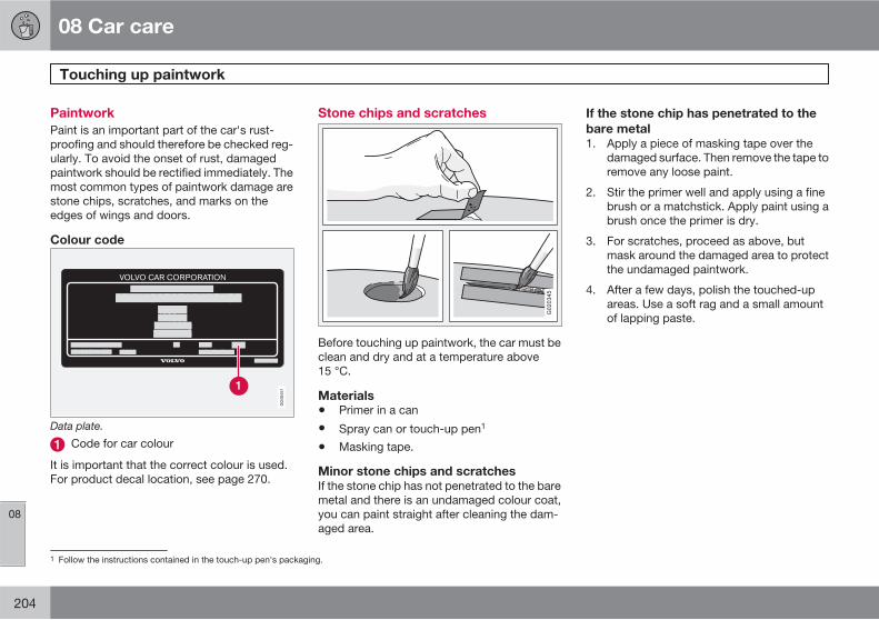
08 Car care
Touching up paintwork
08
204
Paintwork
Paint is an important part of the car's rust-proofing and should therefore be checked reg-ularly. To avoid the onset of rust, damagedpaintwork should be rectified immediately. Themost common types of paintwork damage arestone chips, scratches, and marks on theedges of wings and doors.
Colour code
Data plate.
Code for car colour
It is important that the correct colour is used.For product decal location, see page 270.
Stone chips and scratches
G020345
Before touching up paintwork, the car must beclean and dry and at a temperature above15 °C.
Materials
• Primer in a can
• Spray can or touch-up pen1
• Masking tape.
Minor stone chips and scratches
If the stone chip has not penetrated to the baremetal and there is an undamaged colour coat,you can paint straight after cleaning the dam-aged area.
If the stone chip has penetrated to the
bare metal
1. Apply a piece of masking tape over thedamaged surface. Then remove the tape toremove any loose paint.
2. Stir the primer well and apply using a finebrush or a matchstick. Apply paint using abrush once the primer is dry.
3. For scratches, proceed as above, butmask around the damaged area to protectthe undamaged paintwork.
4. After a few days, polish the touched-upareas. Use a soft rag and a small amountof lapping paste.
1 Follow the instructions contained in the touch-up pen's packaging.
08 Car care
Rustproofing
08
205
Inspection and maintenance
Your car has already received a thorough andcomplete rustproofing at the factory. Parts ofthe body are made of galvanised sheet metal.The underbody is protected by a wear-resis-tant anti-corrosion compound. A thin, pene-trating rustproofing fluid was sprayed into themembers, cavities and closed sections.
Maintain the car's rustproofing.
• Keep the car clean. Hose down the under-body. If using a pressure washer, keep thenozzle at least 30 cm from the painted sur-faces.
• Regularly check and touch-up the rust-proofing treatment as necessary.
The car's rustproofing does not normallyrequire treatment for approximately 12 years.After this period, it should be treated at three-year intervals. If the car needs further treat-ment, Volvo recommends that you engage anauthorised Volvo workshop for assistance.
206
Volvo service......................................................................................... 208Self-maintenance.................................................................................. 209Bonnet and engine compartment......................................................... 210Oils and fluids....................................................................................... 212Wiper blades......................................................................................... 217Battery................................................................................................... 218Replacing bulbs ................................................................................... 220Fuses..................................................................................................... 226
MAINTENANCE AND SERVICE
09 Maintenance and service
Volvo service 09
208
Volvo service programme
Before the car left the factory, it was thoroughlytest driven. It was checked again in accord-ance with Volvo Car Corporation regulationsbefore it was handed over to you.
To keep your Volvo as safe and reliable as pos-sible, follow the Volvo service programmespecified in the Service and Warranty Booklet.Volvo also recommends that you engage anauthorised Volvo workshop to perform theservice and maintenance work. Volvo work-shops have the personnel, special tools andservice literature to guarantee the highest qual-ity of service.
IMPORTANT
For the Volvo warranty to apply, check andfollow the instructions in the Service andWarranty Booklet.
Special service measures
Certain service measures which affect the car'selectrical system can only be performed usingelectronic equipment specially developed foryour car. For this reason, Volvo recommendsthat you always contact an authorised Volvoworkshop before beginning or performingservice work that affects the electrical system.
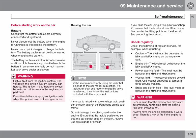
09 Maintenance and service
Self-maintenance 09
209
Before starting work on the car
Battery
Check that the battery cables are correctlyconnected and tightened.
Never disconnect the battery when the engineis running (e.g. if replacing the battery).
Never use a quick charger to charge the bat-tery. The battery cables must be disconnectedwhen charging the battery.
The battery contains acid that is both corrosiveand toxic. It is therefore important to handle thebattery in an environmentally correct manner.Let your Volvo dealer assist you.
WARNING
High output from the ignition system. Thevoltage in the ignition system is highly dan-gerous. The ignition must therefore alwaysbe switched off for work in the engine com-partment.
Do not touch the spark plugs or ignition coilswhen the ignition is on or the engine is hot.
Raising the car
NOTE
Volvo recommends only using the jack thatbelongs to the car model in question. If ajack other than one recommended by Volvois selected, then follow the instructionsincluded with the equipment
If the car is raised with a workshop jack; posi-tion the jack against the front edge on the sub-frame.
Do not damage the splashguard under theengine. Ensure that the jack is positioned sothat the car cannot slide off the jack. Alwaysuse axle stands or similar.
If you raise the car using a two-pillar workshoplift, ensure that the front and rear lift arms arefixed under the lifting points on the door sill.See preceding illustration.
Check regularly
Check the following at regular intervals, forexample, when refuelling:
• Coolant – The level must be between theMIN and MAX marks on the expansiontank.
• Engine oil – The level must be between theMIN and MAX marks.
• Power steering fluid – The level must bebetween the MIN and MAX marks.
• Washer fluid – The reservoir should be wellfilled. Use washer antifreeze at tempera-tures around freezing.
• Brake and clutch fluid – The level must bebetween the MIN and MAX marks.
WARNING
Bear in mind that the radiator fan may startautomatically some time after the enginehas been switched off.
Always have the engine cleaned by a work-shop. There is a risk of fire if the engine ishot.

09 Maintenance and service
Bonnet and engine compartment 09
210
Opening the bonnet
G020793
The illustration shows a left-hand drive car.
1. Pull the handle on the far left under theinstrument panel. (In right-hand drive carsthe handle is on the far right.) You will hearwhen the catch releases.
2. Insert your hand under the centre of thefront edge of the bonnet and press thesafety catch to the right.
3. Open the bonnet.
WARNING
Check that the bonnet locks properly whenclosed.
Engine compartment
Washer fluid reservoir (4-cyl.)
Coolant expansion tank
Reservoir for the power steering fluid (con-cealed behind the headlamp)
Engine oil dipstick1
Radiator
Radiator fan
Washer fluid reservoir (5-cyl.)
Brake and clutch fluid reservoir (right-handdrive)
Filler opening for engine oil1
Brake and clutch fluid reservoir (left-handdrive)
1 The location varies depending on engine alternative
09 Maintenance and service
Bonnet and engine compartment 09
211
Battery
Relay and fuse box, engine compartment
Air filter1
1 The location varies depending on engine alternative
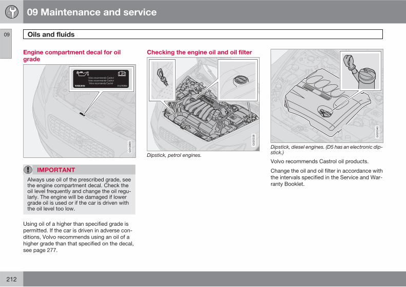
09 Maintenance and service
Oils and fluids 09
212
Engine compartment decal for oilgrade
IMPORTANT
Always use oil of the prescribed grade, seethe engine compartment decal. Check theoil level frequently and change the oil regu-larly. The engine will be damaged if lowergrade oil is used or if the car is driven withthe oil level too low.
Using oil of a higher than specified grade ispermitted. If the car is driven in adverse con-ditions, Volvo recommends using an oil of ahigher grade than that specified on the decal,see page 277.
Checking the engine oil and oil filter
G020338
Dipstick, petrol engines.
G020340
Dipstick, diesel engines. (D5 has an electronic dip-stick.)
Volvo recommends Castrol oil products.
Change the oil and oil filter in accordance withthe intervals specified in the Service and War-ranty Booklet.
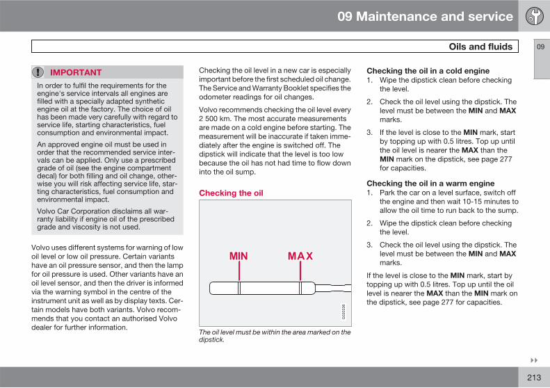
09 Maintenance and service
Oils and fluids 09
��
213
IMPORTANT
In order to fulfil the requirements for theengine's service intervals all engines arefilled with a specially adapted syntheticengine oil at the factory. The choice of oilhas been made very carefully with regard toservice life, starting characteristics, fuelconsumption and environmental impact.
An approved engine oil must be used inorder that the recommended service inter-vals can be applied. Only use a prescribedgrade of oil (see the engine compartmentdecal) for both filling and oil change, other-wise you will risk affecting service life, star-ting characteristics, fuel consumption andenvironmental impact.
Volvo Car Corporation disclaims all war-ranty liability if engine oil of the prescribedgrade and viscosity is not used.
Volvo uses different systems for warning of lowoil level or low oil pressure. Certain variantshave an oil pressure sensor, and then the lampfor oil pressure is used. Other variants have anoil level sensor, and then the driver is informedvia the warning symbol in the centre of theinstrument unit as well as by display texts. Cer-tain models have both variants. Volvo recom-mends that you contact an authorised Volvodealer for further information.
Checking the oil level in a new car is especiallyimportant before the first scheduled oil change.The Service and Warranty Booklet specifies theodometer readings for oil changes.
Volvo recommends checking the oil level every2 500 km. The most accurate measurementsare made on a cold engine before starting. Themeasurement will be inaccurate if taken imme-diately after the engine is switched off. Thedipstick will indicate that the level is too lowbecause the oil has not had time to flow downinto the oil sump.
Checking the oil
G020336
The oil level must be within the area marked on thedipstick.
Checking the oil in a cold engine
1. Wipe the dipstick clean before checkingthe level.
2. Check the oil level using the dipstick. Thelevel must be between the MIN and MAX
marks.
3. If the level is close to the MIN mark, startby topping up with 0.5 litres. Top up untilthe oil level is nearer the MAX than theMIN mark on the dipstick, see page 277for capacities.
Checking the oil in a warm engine
1. Park the car on a level surface, switch offthe engine and then wait 10-15 minutes toallow the oil time to run back to the sump.
2. Wipe the dipstick clean before checkingthe level.
3. Check the oil level using the dipstick. Thelevel must be between the MIN and MAX
marks.
If the level is close to the MIN mark, start bytopping up with 0.5 litres. Top up until the oillevel is nearer the MAX than the MIN mark onthe dipstick, see page 277 for capacities.
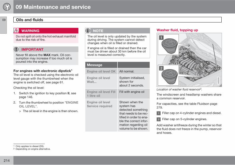
09 Maintenance and service
Oils and fluids 09
214
WARNING
Do not spill oil onto the hot exhaust manifolddue to the risk of fire.
IMPORTANT
Never fill above the MAX mark. Oil con-sumption may increase if too much oil ispoured into the engine.
For engines with electronic dipstick1
The oil level is checked using the electronic oillevel gauge with the thumbwheel when theengine is switched off, see page 61.
Checking the oil level:
1. Switch the ignition to key position II, seepage 146.
2. Turn the thumbwheel to position "ENGINE
OIL LEVEL".> The oil level in the engine is then shown.
NOTE
The oil level is only updated by the systemduring driving. The system cannot detectchanges when oil is filled or drained.
If engine oil is filled or drained then the carmust be driven about 30 km before the oillevel is measured correctly.
Message
Engine oil level OK All normal.
Engine oil level
Wait...
System initialised,shown forabout 2 seconds.
Engine oil level Fill
1 litre oil
Fill with engine oil
Engine oil level
Service required
Shown when thesystem hasdetected somethingthat needs to be rec-tified in order to ena-ble the correct infor-mation regarding oilvolume to be shown.
Washer fluid, topping up
G020335
Location of washer fluid reservoir2.
The windscreen and headlamp washers sharea common reservoir.
For capacities, see the table Fluidson page279.
Filler cap on 4-cylinder engines and diesel.
Filler cap on 5-cylinder engines.
Add washer antifreeze during the winter so thatthe fluid does not freeze in the pump, reservoirand hoses.
1 Only applies to diesel (D5).2 Depending on engine alternative.
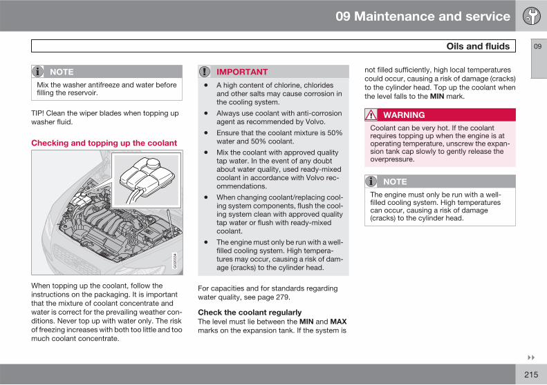
09 Maintenance and service
Oils and fluids 09
��
215
NOTE
Mix the washer antifreeze and water beforefilling the reservoir.
TIP! Clean the wiper blades when topping upwasher fluid.
Checking and topping up the coolant
G020334
When topping up the coolant, follow theinstructions on the packaging. It is importantthat the mixture of coolant concentrate andwater is correct for the prevailing weather con-ditions. Never top up with water only. The riskof freezing increases with both too little and toomuch coolant concentrate.
IMPORTANT
• A high content of chlorine, chloridesand other salts may cause corrosion inthe cooling system.
• Always use coolant with anti-corrosionagent as recommended by Volvo.
• Ensure that the coolant mixture is 50%water and 50% coolant.
• Mix the coolant with approved qualitytap water. In the event of any doubtabout water quality, used ready-mixedcoolant in accordance with Volvo rec-ommendations.
• When changing coolant/replacing cool-ing system components, flush the cool-ing system clean with approved qualitytap water or flush with ready-mixedcoolant.
• The engine must only be run with a well-filled cooling system. High tempera-tures may occur, causing a risk of dam-age (cracks) to the cylinder head.
For capacities and for standards regardingwater quality, see page 279.
Check the coolant regularly
The level must lie between the MIN and MAX
marks on the expansion tank. If the system is
not filled sufficiently, high local temperaturescould occur, causing a risk of damage (cracks)to the cylinder head. Top up the coolant whenthe level falls to the MIN mark.
WARNING
Coolant can be very hot. If the coolantrequires topping up when the engine is atoperating temperature, unscrew the expan-sion tank cap slowly to gently release theoverpressure.
NOTE
The engine must only be run with a well-filled cooling system. High temperaturescan occur, causing a risk of damage(cracks) to the cylinder head.
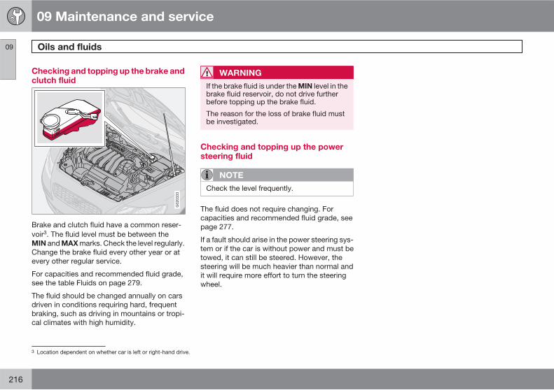
09 Maintenance and service
Oils and fluids 09
216
Checking and topping up the brake andclutch fluid
G020333
Brake and clutch fluid have a common reser-voir3. The fluid level must be between theMIN and MAX marks. Check the level regularly.Change the brake fluid every other year or atevery other regular service.
For capacities and recommended fluid grade,see the table Fluids on page 279.
The fluid should be changed annually on carsdriven in conditions requiring hard, frequentbraking, such as driving in mountains or tropi-cal climates with high humidity.
WARNING
If the brake fluid is under the MIN level in thebrake fluid reservoir, do not drive furtherbefore topping up the brake fluid.
The reason for the loss of brake fluid mustbe investigated.
Checking and topping up the powersteering fluid
NOTE
Check the level frequently.
The fluid does not require changing. Forcapacities and recommended fluid grade, seepage 277.
If a fault should arise in the power steering sys-tem or if the car is without power and must betowed, it can still be steered. However, thesteering will be much heavier than normal andit will require more effort to turn the steeringwheel.
3 Location dependent on whether car is left or right-hand drive.
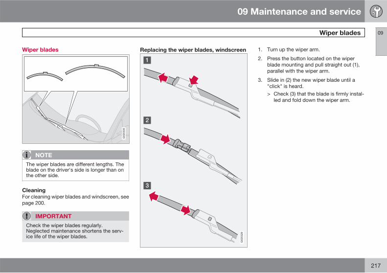
09 Maintenance and service
Wiper blades 09
217
Wiper blades
G020330
NOTE
The wiper blades are different lengths. Theblade on the driver's side is longer than onthe other side.
Cleaning
For cleaning wiper blades and windscreen, seepage 200.
IMPORTANT
Check the wiper blades regularly.Neglected maintenance shortens the serv-ice life of the wiper blades.
Replacing the wiper blades, windscreen
G020329
1. Turn up the wiper arm.
2. Press the button located on the wiperblade mounting and pull straight out (1),parallel with the wiper arm.
3. Slide in (2) the new wiper blade until a"click" is heard.> Check (3) that the blade is firmly instal-
led and fold down the wiper arm.
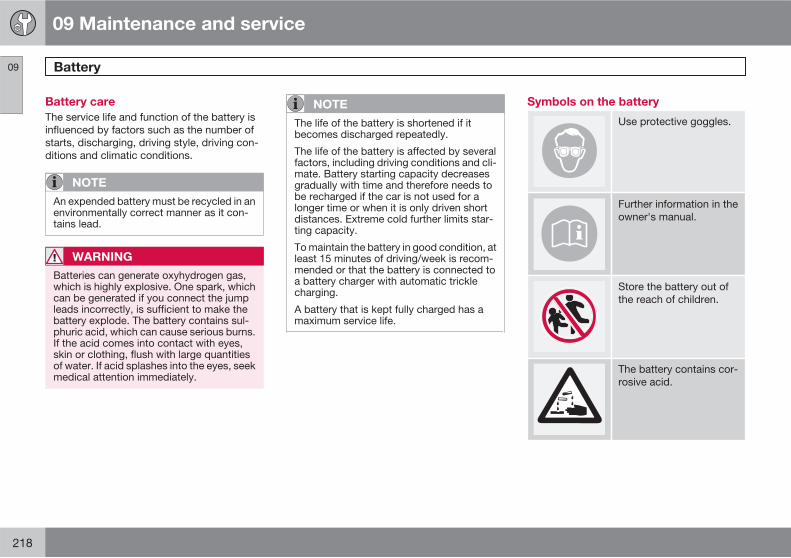
09 Maintenance and service
Battery 09
218
Battery care
The service life and function of the battery isinfluenced by factors such as the number ofstarts, discharging, driving style, driving con-ditions and climatic conditions.
NOTE
An expended battery must be recycled in anenvironmentally correct manner as it con-tains lead.
WARNING
Batteries can generate oxyhydrogen gas,which is highly explosive. One spark, whichcan be generated if you connect the jumpleads incorrectly, is sufficient to make thebattery explode. The battery contains sul-phuric acid, which can cause serious burns.If the acid comes into contact with eyes,skin or clothing, flush with large quantitiesof water. If acid splashes into the eyes, seekmedical attention immediately.
NOTE
The life of the battery is shortened if itbecomes discharged repeatedly.
The life of the battery is affected by severalfactors, including driving conditions and cli-mate. Battery starting capacity decreasesgradually with time and therefore needs tobe recharged if the car is not used for alonger time or when it is only driven shortdistances. Extreme cold further limits star-ting capacity.
To maintain the battery in good condition, atleast 15 minutes of driving/week is recom-mended or that the battery is connected toa battery charger with automatic tricklecharging.
A battery that is kept fully charged has amaximum service life.
Symbols on the battery
Use protective goggles.
Further information in theowner's manual.
Store the battery out ofthe reach of children.
The battery contains cor-rosive acid.
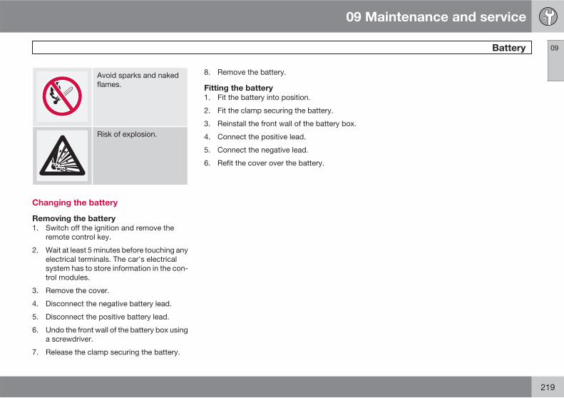
09 Maintenance and service
Battery 09
219
Avoid sparks and nakedflames.
Risk of explosion.
Changing the battery
Removing the battery
1. Switch off the ignition and remove theremote control key.
2. Wait at least 5 minutes before touching anyelectrical terminals. The car's electricalsystem has to store information in the con-trol modules.
3. Remove the cover.
4. Disconnect the negative battery lead.
5. Disconnect the positive battery lead.
6. Undo the front wall of the battery box usinga screwdriver.
7. Release the clamp securing the battery.
8. Remove the battery.
Fitting the battery
1. Fit the battery into position.
2. Fit the clamp securing the battery.
3. Reinstall the front wall of the battery box.
4. Connect the positive lead.
5. Connect the negative lead.
6. Refit the cover over the battery.
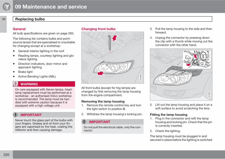
09 Maintenance and service
Replacing bulbs 09
220
General
All bulb specifications are given on page 283.
The following list contains bulbs and point-source lamps that are specialised or unsuitablefor changing except at a workshop:
• General interior lighting in the roof
• Reading lamps, courtesy lighting and glo-vebox lighting
• Direction indicators, door mirror andapproach lighting
• Brake light
• Active Bending Lights (ABL)
WARNING
On cars equipped with Xenon lamps, head-lamp replacement must be performed at aworkshop - an authorised Volvo workshopis recommended. The lamp must be han-dled with extreme caution because it isequipped with a high voltage unit.
IMPORTANT
Never touch the glass part of the bulbs withyour fingers. Grease and oil from your fin-gers are vaporised by the heat, coating thereflector and then causing damage.
Changing front bulbs
G019599
All front bulbs (except for fog lamps) arechanged by first removing the lamp housingfrom the engine compartment.
Removing the lamp housing
1. Remove the remote control key and turnthe light switch to position 0.
2. Withdraw the lamp housing's locking pin.
IMPORTANT
Do not pull the electrical cable, only the con-nector.
3. Pull the lamp housing to the side and thenforward.
4. Unplug the connector by pressing downthe clip with a thumb while moving out theconnector with the other hand.
G019600
5. Lift out the lamp housing and place it on asoft surface to avoid scratching the lens.
Fitting the lamp housing
1. Plug in the connector and refit the lamphousing and locking pin. Check that the pinis correctly inserted.
2. Check the lighting.
The lamp housing must be plugged in andsecured in place before the lighting is switched
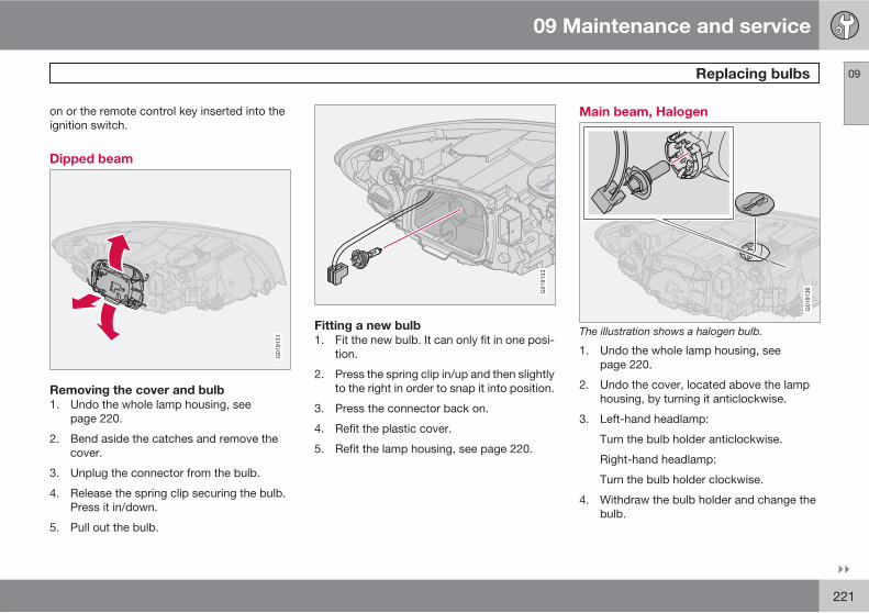
09 Maintenance and service
Replacing bulbs 09
��
221
on or the remote control key inserted into theignition switch.
Dipped beam
G019131
Removing the cover and bulb
1. Undo the whole lamp housing, seepage 220.
2. Bend aside the catches and remove thecover.
3. Unplug the connector from the bulb.
4. Release the spring clip securing the bulb.Press it in/down.
5. Pull out the bulb.G019133
Fitting a new bulb
1. Fit the new bulb. It can only fit in one posi-tion.
2. Press the spring clip in/up and then slightlyto the right in order to snap it into position.
3. Press the connector back on.
4. Refit the plastic cover.
5. Refit the lamp housing, see page 220.
Main beam, Halogen
G019136
The illustration shows a halogen bulb.
1. Undo the whole lamp housing, seepage 220.
2. Undo the cover, located above the lamphousing, by turning it anticlockwise.
3. Left-hand headlamp:
Turn the bulb holder anticlockwise.
Right-hand headlamp:
Turn the bulb holder clockwise.
4. Withdraw the bulb holder and change thebulb.
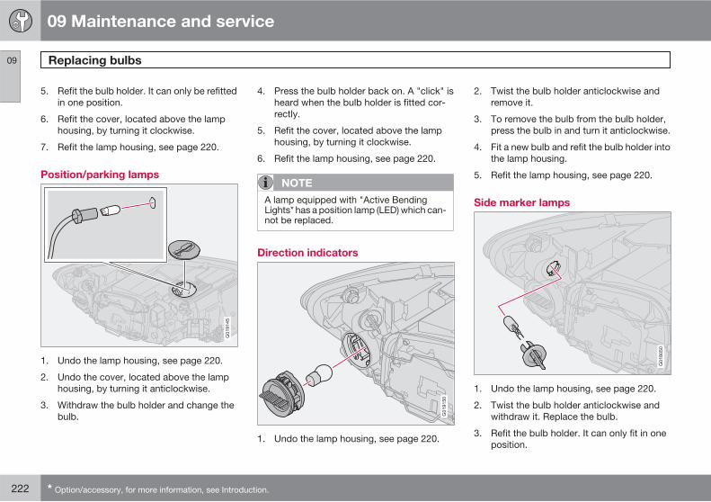
09 Maintenance and service
Replacing bulbs 09
222 * Option/accessory, for more information, see Introduction.
5. Refit the bulb holder. It can only be refittedin one position.
6. Refit the cover, located above the lamphousing, by turning it clockwise.
7. Refit the lamp housing, see page 220.
Position/parking lamps
G019145
1. Undo the lamp housing, see page 220.
2. Undo the cover, located above the lamphousing, by turning it anticlockwise.
3. Withdraw the bulb holder and change thebulb.
4. Press the bulb holder back on. A "click" isheard when the bulb holder is fitted cor-rectly.
5. Refit the cover, located above the lamphousing, by turning it clockwise.
6. Refit the lamp housing, see page 220.
NOTE
A lamp equipped with "Active BendingLights* has a position lamp (LED) which can-not be replaced.
Direction indicators
G019150
1. Undo the lamp housing, see page 220.
2. Twist the bulb holder anticlockwise andremove it.
3. To remove the bulb from the bulb holder,press the bulb in and turn it anticlockwise.
4. Fit a new bulb and refit the bulb holder intothe lamp housing.
5. Refit the lamp housing, see page 220.
Side marker lamps
G018050
1. Undo the lamp housing, see page 220.
2. Twist the bulb holder anticlockwise andwithdraw it. Replace the bulb.
3. Refit the bulb holder. It can only fit in oneposition.
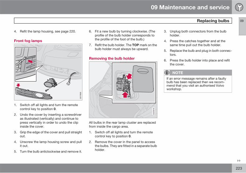
09 Maintenance and service
Replacing bulbs 09
��
223
4. Refit the lamp housing, see page 220.
Front fog lamps
G017609
1. Switch off all lights and turn the remotecontrol key to position 0.
2. Undo the cover by inserting a screwdriveras illustrated (vertically) and continue topress vertically in order to undo the clipinside the cover.
3. Grip the edge of the cover and pull straightout.
4. Unscrew the lamp housing screw and pullit out.
5. Turn the bulb anticlockwise and remove it.
6. Fit a new bulb by turning clockwise. (Theprofile of the bulb holder corresponds tothe profile of the foot of the bulb.)
7. Refit the bulb holder. The TOP mark on thebulb holder must always be upward.
Removing the bulb holder
G020916
All bulbs in the rear lamp cluster are replacedfrom inside the cargo area.
1. Switch off all lights and turn the remotecontrol key to position 0.
2. Remove the cover in the panel to accessthe bulbs. They are fitted in a separate bulbholder.
3. Unplug both connectors from the bulbholder.
4. Press the catches together and at thesame time pull out the bulb holder.
5. Replace the bulb and plug in both connec-tors.
6. Press the bulb holder into place and refitthe cover.
NOTE
If an error message remains after a faultybulb has been replaced then we recom-mend that you visit an authorised Volvoworkshop.
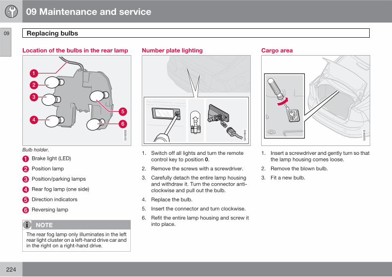
09 Maintenance and service
Replacing bulbs 09
224
Location of the bulbs in the rear lamp
G018055
Bulb holder.
Brake light (LED)
Position lamp
Position/parking lamps
Rear fog lamp (one side)
Direction indicators
Reversing lamp
NOTE
The rear fog lamp only illuminates in the leftrear light cluster on a left-hand drive car andin the right on a right-hand drive.
Number plate lighting
G014843
1. Switch off all lights and turn the remotecontrol key to position 0.
2. Remove the screws with a screwdriver.
3. Carefully detach the entire lamp housingand withdraw it. Turn the connector anti-clockwise and pull out the bulb.
4. Replace the bulb.
5. Insert the connector and turn clockwise.
6. Refit the entire lamp housing and screw itinto place.
Cargo area
G020915
1. Insert a screwdriver and gently turn so thatthe lamp housing comes loose.
2. Remove the blown bulb.
3. Fit a new bulb.
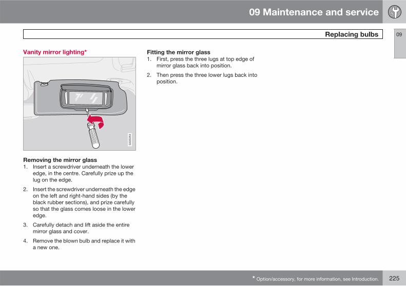
09 Maintenance and service
Replacing bulbs 09
* Option/accessory, for more information, see Introduction. 225
Vanity mirror lighting*
G020253
Removing the mirror glass
1. Insert a screwdriver underneath the loweredge, in the centre. Carefully prize up thelug on the edge.
2. Insert the screwdriver underneath the edgeon the left and right-hand sides (by theblack rubber sections), and prize carefullyso that the glass comes loose in the loweredge.
3. Carefully detach and lift aside the entiremirror glass and cover.
4. Remove the blown bulb and replace it witha new one.
Fitting the mirror glass
1. First, press the three lugs at top edge ofmirror glass back into position.
2. Then press the three lower lugs back intoposition.
09 Maintenance and service
Fuses 09
226
General
All electrical functions and components arefused to protect the car's electrical systemfrom damage by short circuiting and overload-ing.
The fuses are in two different locations in thecar:
• Relay/Fuse box in the engine compart-ment.
• Relay/Fuse box in the passenger compart-ment.
Changing
If an electrical component or function does notwork, it may be because the component's fusewas temporarily overloaded and blew.
1. Look in the fuse diagram to locate the fuse.
2. Pull out the fuse and check from the sideto see whether the curved wire has blown.
3. If this is the case, replace it with a new fuseof the same colour and amperage.
Each fuse box has space for several sparefuses. If the same fuse fails repeatedly thenthere is a fault in the component. In which case,Volvo recommends that you visit an authorisedVolvo workshop for this to be checked.
WARNING
Never use a foreign object, or a fuse with anamperage higher than that specified whenreplacing a fuse. This could cause signifi-cant damage to the electrical system andpossibly lead to fire.
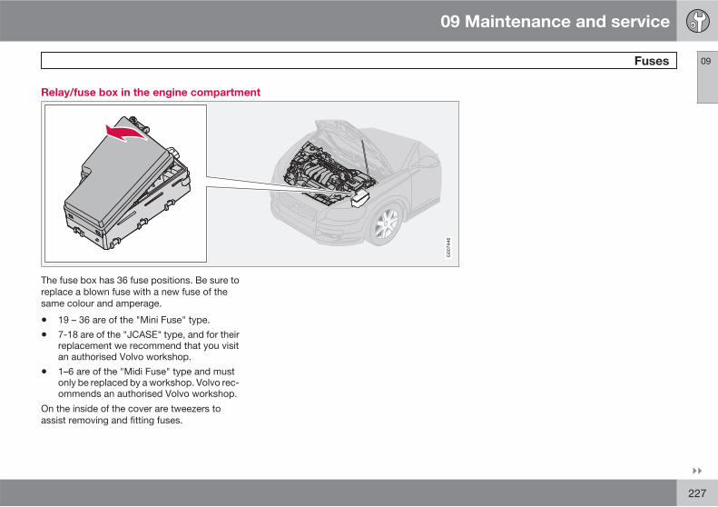
09 Maintenance and service
Fuses 09
��
227
Relay/fuse box in the engine compartment
G007446
The fuse box has 36 fuse positions. Be sure toreplace a blown fuse with a new fuse of thesame colour and amperage.
• 19 – 36 are of the "Mini Fuse" type.
• 7-18 are of the "JCASE" type, and for theirreplacement we recommend that you visitan authorised Volvo workshop.
• 1–6 are of the "Midi Fuse" type and mustonly be replaced by a workshop. Volvo rec-ommends an authorised Volvo workshop.
On the inside of the cover are tweezers toassist removing and fitting fuses.
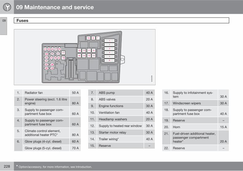
09 Maintenance and service
Fuses 09
228 * Option/accessory, for more information, see Introduction.
G020250
1. Radiator fan 50 A
2. Power steering (excl. 1.6 litreengine) 80 A
3. Supply to passenger com-partment fuse box 60 A
4. Supply to passenger com-partment fuse box 60 A
5. Climate control element,additional heater PTC* 80 A
6. Glow plugs (4-cyl. diesel) 60 A
Glow plugs (5-cyl. diesel) 70 A
7. ABS pump 40 A
8. ABS valves 20 A
9. Engine functions 30 A
10. Ventilation fan 40 A
11. Headlamp washers 20 A
12. Supply to heated rear window 30 A
13. Starter motor relay 30 A
14. Trailer wiring* 40 A
15. Reserve –
16. Supply to infotainment sys-tem 30 A
17. Windscreen wipers 30 A
18. Supply to passenger com-partment fuse box 40 A
19. Reserve –
20. Horn 15 A
21. Fuel-driven additional heater,passenger compartmentheater* 20 A
22. Reserve –
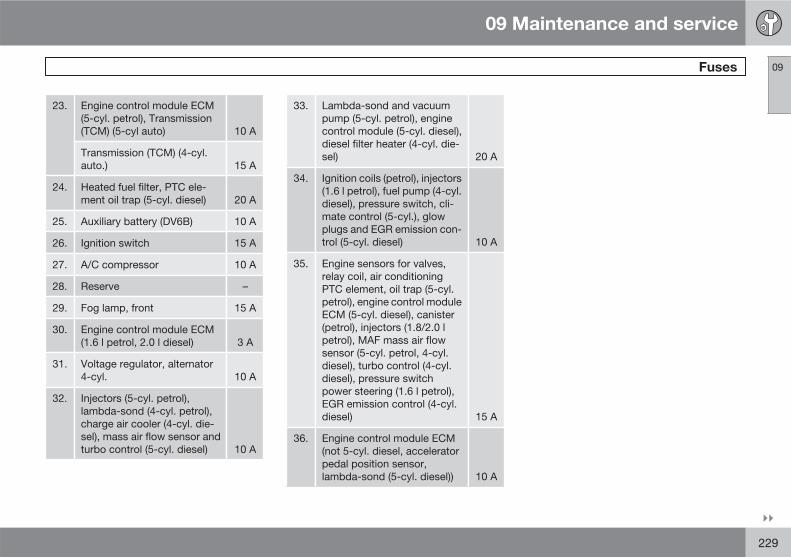
09 Maintenance and service
Fuses 09
��
229
23. Engine control module ECM(5-cyl. petrol), Transmission(TCM) (5-cyl auto) 10 A
Transmission (TCM) (4-cyl.auto.) 15 A
24. Heated fuel filter, PTC ele-ment oil trap (5-cyl. diesel) 20 A
25. Auxiliary battery (DV6B) 10 A
26. Ignition switch 15 A
27. A/C compressor 10 A
28. Reserve –
29. Fog lamp, front 15 A
30. Engine control module ECM(1.6 l petrol, 2.0 l diesel) 3 A
31. Voltage regulator, alternator4-cyl. 10 A
32. Injectors (5-cyl. petrol),lambda-sond (4-cyl. petrol),charge air cooler (4-cyl. die-sel), mass air flow sensor andturbo control (5-cyl. diesel) 10 A
33. Lambda-sond and vacuumpump (5-cyl. petrol), enginecontrol module (5-cyl. diesel),diesel filter heater (4-cyl. die-sel) 20 A
34. Ignition coils (petrol), injectors(1.6 l petrol), fuel pump (4-cyl.diesel), pressure switch, cli-mate control (5-cyl.), glowplugs and EGR emission con-trol (5-cyl. diesel) 10 A
35. Engine sensors for valves,relay coil, air conditioningPTC element, oil trap (5-cyl.petrol), engine control moduleECM (5-cyl. diesel), canister(petrol), injectors (1.8/2.0 lpetrol), MAF mass air flowsensor (5-cyl. petrol, 4-cyl.diesel), turbo control (4-cyl.diesel), pressure switchpower steering (1.6 l petrol),EGR emission control (4-cyl.diesel) 15 A
36. Engine control module ECM(not 5-cyl. diesel, acceleratorpedal position sensor,lambda-sond (5-cyl. diesel)) 10 A

09 Maintenance and service
Fuses 09
230
Relay/Fuse box in the passenger compartment
G020601
The fuse box has 50 fuse positions. The fusesare located under the glovebox. The box alsoprovides space for several spare fuses. Toolsfor fuse replacement are located in the relay/fuse box in the engine compartment, seepage 227.
Replacing fuses
1. Remove the trim concealing the fuse boxby pressing in the pin in the centre of theclips (1) about one cm and then withdraw-ing the clips.
2. Turn the two wing screws (that secure thefuse box) (2) anticlockwise and removethem.
3. Lower the fuse box (3) half way. Pull ittowards the seat until it stops. Lower it
completely. The fuse box can be fullyunhooked.
4. Close the fuse box in the reverse order.
5. Remove the pins from the centre of theclips. Fit the trim and the clips. Reinsert thepins into the clips. This expands the clipsand secures the trim.
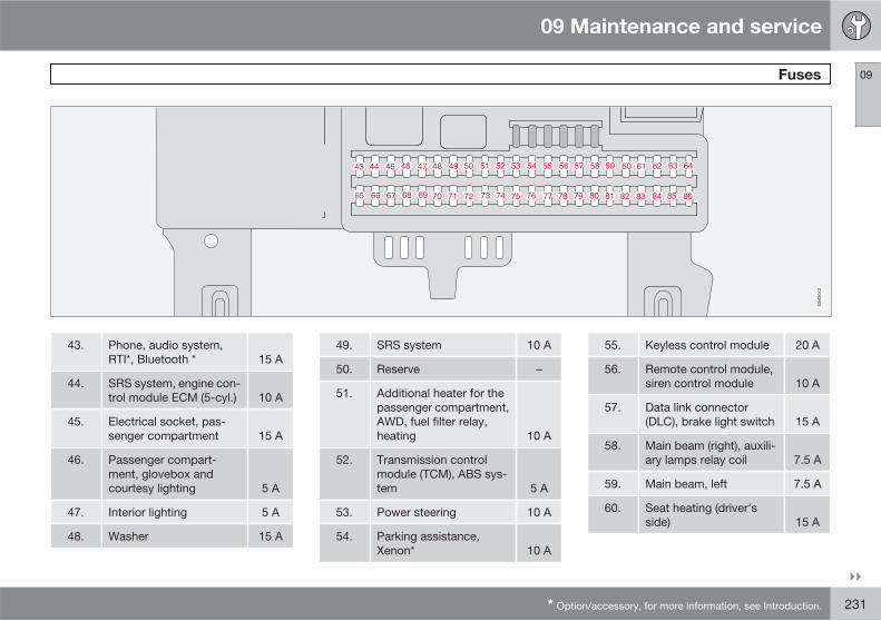
09 Maintenance and service
Fuses 09
��
* Option/accessory, for more information, see Introduction. 231
43. Phone, audio system,RTI*, Bluetooth * 15 A
44. SRS system, engine con-trol module ECM (5-cyl.) 10 A
45. Electrical socket, pas-senger compartment 15 A
46. Passenger compart-ment, glovebox andcourtesy lighting 5 A
47. Interior lighting 5 A
48. Washer 15 A
49. SRS system 10 A
50. Reserve –
51. Additional heater for thepassenger compartment,AWD, fuel filter relay,heating 10 A
52. Transmission controlmodule (TCM), ABS sys-tem 5 A
53. Power steering 10 A
54. Parking assistance,Xenon* 10 A
55. Keyless control module 20 A
56. Remote control module,siren control module 10 A
57. Data link connector(DLC), brake light switch 15 A
58. Main beam (right), auxili-ary lamps relay coil 7.5 A
59. Main beam, left 7.5 A
60. Seat heating (driver'sside) 15 A
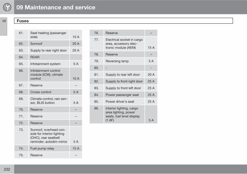
09 Maintenance and service
Fuses 09
232
61. Seat heating (passengerside) 15 A
62. Sunroof 20 A
63. Supply to rear right door 20 A
64. RDAR
65. Infotainment system 5 A
66. Infotainment controlmodule (ICM), climatecontrol 10 A
67. Reserve –
68. Cruise control 5 A
69. Climate control, rain sen-sor, BLIS button 5 A
70. Reserve –
71. Reserve –
72. Reserve –
73. Sunroof, overhead con-sole for interior lighting(OHC), rear seatbeltreminder, autodim mirror 5 A
74. Fuel pump relay 15 A
75. Reserve –
76. Reserve –
77. Electrical socket in cargoarea, accessory elec-tronic module (AEM) 15 A
78. Reserve –
79. Reversing lamp 5 A
80. - -
81. Supply to rear left door 20 A
82. Supply to front right door 25 A
83. Supply to front left door 25 A
84. Power passenger seat 25 A
85. Power driver's seat 25 A
86. Interior lighting, cargoarea lighting, powerseats, fuel level display(1.8F) 5 A
09 Maintenance and service
09
233
234 * Option/accessory, for more information, see Introduction.
General.................................................................................................. 236Audio functions..................................................................................... 238Radio functions..................................................................................... 242CD functions ........................................................................................ 247Menu structure – audio system............................................................. 250Phone functions*................................................................................... 251Menu structure – phone*....................................................................... 258Bluetooth handsfree* ........................................................................... 261
INFOTAINMENT SYSTEM
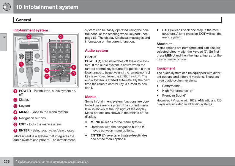
10 Infotainment system
General
10
236 * Option/accessory, for more information, see Introduction.
Infotainment system
G020245
POWER - Pushbutton, audio system on/off
Display
Keypad
MENU - Goes to the menu system
Navigation buttons
EXIT - Exits the menu system
ENTER - Selects/activates/deactivates
Infotainment is a system that integrates theaudio system and phone*. The infotainment
system can be easily operated using the con-trol panel or the steering wheel keypad*, seepage 67. The display (2) shows messages andinformation on the current function.
Audio system
On/Off
POWER (1) starts/switches off the audio sys-tem. If the audio system is active when theremote control key is turned to position 0 thenit continues to be active until the remote controlkey is removed from the ignition switch. Theaudio system is started automatically the nexttime the remote control key is turned to posi-tion I.
Menus
Some infotainment system functions are con-trolled via a menu system. The current menulevel is shown at the top right of the display.Menu options are shown in the middle of thedisplay.
• MENU (4) leads to the menu system.
• Up/down with the navigation button (5)moves between menu options.
• ENTER (7) selects/activates/deactivatesone of the menu options.
• EXIT (6) leads back one step in the menustructure. A long press on EXIT will exit themenu system.
Shortcuts
Menu options are numbered and can also beselected directly with the keypad (3). So firstpress MENU and then the figure/figures for thedesired menu option.
Equipment
The audio system can be equipped with differ-ent options and different versions. There arethree audio system versions:
• Performance,
• High Performance* or
• Premuim Sound*
However, FM radio with RDS, AM radio and CDplayer are included in all audio systems.
10 Infotainment system
General
10
237
Dolby Surround Pro Logic II 1
Dolby Surround Pro Logic II distributes thetwo stereo audio channels to left, centre, rightand rear speakers. This provides a more real-istic sound quality than that provided by stand-ard two-channel stereo.
Dolby Surround Pro Logic II and the Dolbyicon are trademarks of Dolby LaboratoriesLicensing Corporation.
Dolby Surround Pro Logic II System is manu-factured under license from Dolby LaboratoriesLicensing Corporation.
1 Premium Sound.
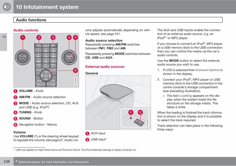
10 Infotainment system
Audio functions
10
238 * Option/accessory, for more information, see Introduction.
Audio controls
VOLUME - Knob
AM/FM – Audio source selection
MODE - Audio source selection, CD, AUXand USB (e.g. iPod )1
TUNING - Knob
SOUND - Button
Navigation button - Menus
Volume
Use VOLUME (1) or the steering wheel keypadto regulate the volume, see page 67. Audio vol-
ume adjusts automatically depending on vehi-cle speed, see page 241.
Audio source selection
Repeatedly pressing AM/FM switchesbetween FM1, FM2 and AM.
Repeatedly pressing MODE switches betweenCD, USB and AUX.
External audio sources
General
AUX input
USB input*
The AUX and USB inputs enable the connec-tion of an external audio source, e.g. aniPod 1 or MP3 player.
If you choose to connect an iPod , MP3 playeror a USB memory stick to the USB connectionthen you can control the media via the car'saudio controls.
Use the MODE button to select the externalaudio source you wish to use.
1. If USB is selected then Connect device isshown in the display.
2. Connect your iPod , MP3 player or USBmemory stick to the USB connection in thecentre console's storage compartment(see preceding illustration).> The text Loading appears on the dis-
play when the system loads the filestructure on the storage media. Thistakes a while.
When the loading is finished the track informa-tion is shown on the display and it is possibleto select the track required.
Track selection can take place in the followingthree ways:
1 USB only applies for High Performance and Premium Sound. The iPod trademark belongs to Apple Computer Inc.
10 Infotainment system
Audio functions
10
��
239
• Select TUNING (4) clockwise or anticlock-wise.
• Use the right or left-hand button (6) of thenavigation control to scroll to the desiredtrack.
• With the steering wheel keypad.
In USB or iPod mode the infotainment systemoperates in an equivalent way to theCD player for playing back music files. Formore information, see page 247.
NOTE
The system supports the playback of musicfiles in the MP3, WMA and WAV file formats.However, there are variants of these file for-mats that are not supported by the system.The system also supports most iPod mod-els produced in 2005 or later. iPod Shuffleis not supported.
USB memory
To facilitate the use of USB memory avoid stor-ing any files other than music files in the mem-ory. It takes considerably longer for the systemto load storage media that contains items otherthan playable music files.
NOTE
The system supports removable mediawhich is compatible with USB 2.0 and theFAT32 file system, and can handle a maxi-mum of 500 folders and 64 000 files. Thememory must have a capacity of at least 256Mb.
MP3 player
Many MP3 players have their own file systemsthat are not supported by the audio system. Foruse in the system, an MP3 player must be setin USB Removable device/Mass Storage
Device mode.
iPod
An iPod is charged and supplied with powerby the USB connection via the player's con-nection cable. However, if the player's batteryis completely discharged then it must becharged before the player is connected.
NOTE
When an iPod is used as audio source, thecar's infotainment system has a menustructure that is similar to the iPod player'sown menu structure.
For information on USB and iPod in combi-nation with Performance audio, see the acces-
sory manual for USB and iPod Music Inter-face.
AUX
Sometimes the AUX external audio source canbe heard at a different volume to the internalaudio sources, e.g. the CD player. If the audiovolume of the external audio source is too highthen the sound quality can be impaired. Pre-vent this by adjusting the input volume of theAUX input.
NOTE
The sound quality may be impaired if theplayer is charged while the audio system isin AUX mode, so avoid charging the player.
Audio settings
Adjusting audio settings
Press SOUND (5) repeatedly to browse amongthe following options. Adjust by turningTUNING.
• BASS - Bass level.
• TREBLE - Treble level.
• FADER – Balance between the front andrear speakers.
• BALANCE – Balance between the left andright-hand speakers.
10 Infotainment system
Audio functions
10
240 * Option/accessory, for more information, see Introduction.
• SUBWOOFER* - Bass speaker level. Sub-woofer must be activated before adjust-ment is possible, see under the headingActivating/deactivating the subwooferbelow.
• CENTRE2 - Level for centre speaker.Three channel stereo or Pro Logic II mustbe activated before adjustment is possible,see under the heading Activating/deacti-vating surround sound below.
• SURROUND2 - Level for surround. ProLogic II must be activated before adjust-ment is possible, see under the headingAudio settings below.
Activating/deactivating the subwoofer
• Press MENU and then ENTER.
• Scroll to Audio settings… and pressENTER.
• Scroll to Subwoofer and press ENTER.
Surround2
Surround settings govern the spatialperception of the sound. Settingsand activating/deactivating are sep-arate for each audio source.
G021216
The Dolby icon in the display indicates thatDolby Pro Logic II is active. There are threedifferent settings for surround sound:
• Dolby Pro Logic II
• 3 channel
• Off - 2 channel stereo.
Activating/deactivating surround sound
1. Press MENU and then ENTER.
2. Scroll to Audio settings… and pressENTER.
3. Scroll to Surround FM…, Surround
AM…, Surround CD…or Surround
AUX… and press ENTER.
4. Scroll to Dolby Pro Logic II3, 3 channel
or Off and press ENTER.
Equalizer front/rear4
The equalizer can be used to adjust differentfrequency bands separately.
Adjusting equalizer
1. Press MENU and then ENTER.
2. Scroll to Audio settings… and pressENTER.
3. Scroll to Equalizer front… or Equalizer
rear… and press ENTER.
4. The graphic on the display indicates theaudio level of the frequency in question.
5. Adjust the level with TUNING (4) or up/down with the navigation button. Addi-tional frequencies can be selected usingthe left/right navigation button.
6. Save with ENTER or EXIT to exit withoutsaving the settings.
2 Premium Sound.3 Not available in AM and FM mode.4 Certain audio systems.
10 Infotainment system
Audio functions
10
* Option/accessory, for more information, see Introduction. 241
Automatic volume control5
The auto volume control function allows theaudio volume to increase as the speed of thecar increases. There are three levels to choosefrom: Low, Medium and High.
Adjusting automatic volume control
1. Press MENU and then ENTER.
2. Scroll to Audio settings… and pressENTER.
3. Scroll to Auto. volume control… andpress ENTER.
4. Scroll to Low, Medium or High and pressENTER.
Optimum sound reproduction
The audio system is calibrated for optimumsound reproduction by means of digital signalprocessing.
This calibration takes into account loudspeak-ers, amplifiers, passenger compartmentacoustics, listener position etc. for each com-bination of car model and audio system.
There is a also a dynamic calibration that takesinto account the position of the volume control,radio reception and vehicle speed.
The controls explained in these operatinginstructions, e.g. bass, treble and equalizer*
are only intended for the user to be able toadapt the sound reproduction according topersonal taste.
5 Not Performance
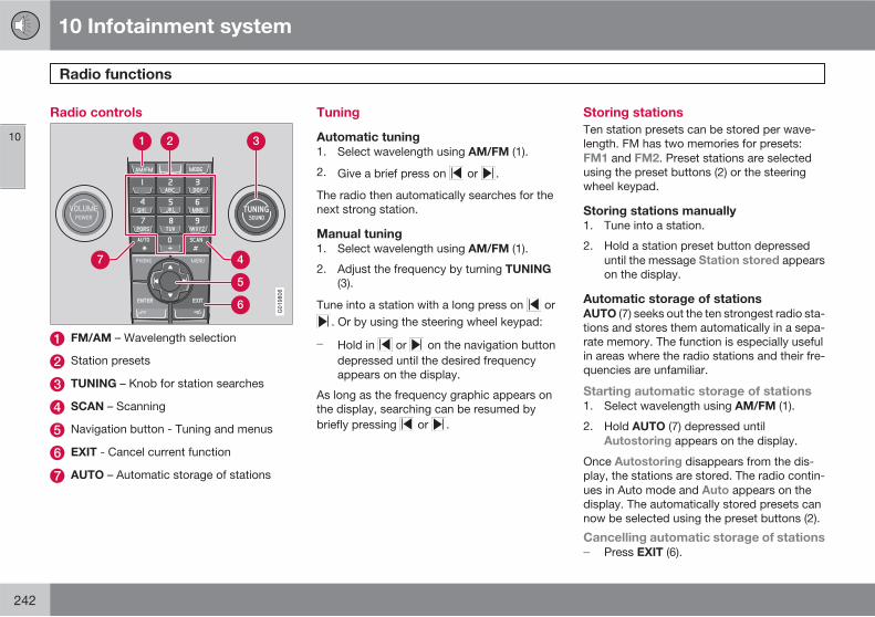
10 Infotainment system
Radio functions
10
242
Radio controls
G019806
FM/AM – Wavelength selection
Station presets
TUNING – Knob for station searches
SCAN – Scanning
Navigation button - Tuning and menus
EXIT - Cancel current function
AUTO – Automatic storage of stations
Tuning
Automatic tuning
1. Select wavelength using AM/FM (1).
2. Give a brief press on or .
The radio then automatically searches for thenext strong station.
Manual tuning
1. Select wavelength using AM/FM (1).
2. Adjust the frequency by turning TUNING
(3).
Tune into a station with a long press on or. Or by using the steering wheel keypad:
� Hold in or on the navigation buttondepressed until the desired frequencyappears on the display.
As long as the frequency graphic appears onthe display, searching can be resumed bybriefly pressing or .
Storing stations
Ten station presets can be stored per wave-length. FM has two memories for presets:FM1 and FM2. Preset stations are selectedusing the preset buttons (2) or the steeringwheel keypad.
Storing stations manually
1. Tune into a station.
2. Hold a station preset button depresseduntil the message Station stored appearson the display.
Automatic storage of stations
AUTO (7) seeks out the ten strongest radio sta-tions and stores them automatically in a sepa-rate memory. The function is especially usefulin areas where the radio stations and their fre-quencies are unfamiliar.
Starting automatic storage of stations
1. Select wavelength using AM/FM (1).
2. Hold AUTO (7) depressed untilAutostoring appears on the display.
Once Autostoring disappears from the dis-play, the stations are stored. The radio contin-ues in Auto mode and Auto appears on thedisplay. The automatically stored presets cannow be selected using the preset buttons (2).
Cancelling automatic storage of stations
� Press EXIT (6).
10 Infotainment system
Radio functions
10
��
243
Selecting an auto-stored preset
Allowing the radio to remain in Auto mode pro-vides access to the autostored presets.
1. Briefly press AUTO (7).> Auto appears on the display.
2. Press a preset button (2).> The radio remains in Auto mode until it
is exited by a brief press on AUTO (7),EXIT (6) or AM/FM (1) cancels Automode.
Storing autostored presets in another
memory
An autostored preset can be transferred to theFM or AM memory.
1. Briefly press AUTO (7).> Auto appears on the display.
2. Press the preset button for the station youwant to move.
3. Press the button under which the stationwill be stored and hold it depressed untilthe message Station stored appears onthe display.> The radio exits Auto mode and the
stored station can be selected as a pre-set.
Scanning
SCAN (4) automatically searches through awavelength for strong stations. When a stationis found, it is played for approx. 8 secondsbefore scanning is resumed.
Activating/deactivating Scan
1. Select wavelength using AM/FM.
2. Press SCAN to activate.> SCAN appears on the display. Close
using SCAN or EXIT.
Storing a station
A selected station can be stored as a presetwhile SCAN is active.
� Press a station preset button and hold itdepressed until the message Station
stored appears on the display.> Scanning is interrupted and the stored
station can be selected as a preset.
RDS functions
Radio Data System - RDS links FM transmittersinto a network. An FM transmitter in such anetwork sends information that gives anRDS radio the following functions:
• Automatically switches to a stronger trans-mitter if reception in the area is poor.
• Searches for programme form, such astraffic information or news.
• Receives text information on current radioprogramme.
Some radio stations do not use RDS or onlysome if its functionality.
Programme functions
In FM mode, the radio can search for stationswith certain programme types. If a requiredprogramme type is located the radio canswitch stations interrupting the audio sourcecurrently in use. For example, if the CD playeris in use, it is paused. The interrupting trans-mission is played at a preset audio volume, seepage 246. The radio returns to the previousaudio source and audio volume when the setprogramme type is no longer broadcast.
The programme functions alarm (ALARM!),traffic information (TP), news (News), and pro-gramme types (PTY) interrupt one another inorder of priority, where alarm has the highestpriority and programme types has the lowest.
If you want to return to the interrupted audiosource before the message or programme typehas been completed, press EXIT.
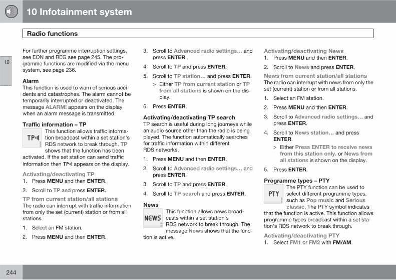
10 Infotainment system
Radio functions
10
244
For further programme interruption settings,see EON and REG see page 245. The pro-gramme functions are modified via the menusystem, see page 236.
Alarm
This function is used to warn of serious acci-dents and catastrophes. The alarm cannot betemporarily interrupted or deactivated. Themessage ALARM! appears on the displaywhen an alarm message is transmitted.
Traffic information – TP
This function allows traffic informa-tion broadcast within a set station'sRDS network to break through. TP
shows that the function has beenactivated. If the set station can send trafficinformation then appears on the display.
G021220
Activating/deactivating TP
1. Press MENU and then ENTER.
2. Scroll to TP and press ENTER.
TP from current station/all stations
The radio can interrupt with traffic informationfrom only the set (current) station or from allstations.
1. Select an FM station.
2. Press MENU and then ENTER.
3. Scroll to Advanced radio settings… andpress ENTER.
4. Scroll to TP and press ENTER.
5. Scroll to TP station… and press ENTER.> Either TP from current station or TP
from all stations is shown on the dis-play.
6. Press ENTER.
Activating/deactivating TP search
TP search is useful during long journeys whilean audio source other than the radio is beingplayed. The function automatically searchesfor traffic information within differentRDS networks.
1. Press MENU and then ENTER.
2. Scroll to Advanced radio settings… andpress ENTER.
3. Scroll to TP and press ENTER.
4. Scroll to TP search and press ENTER.
News
This function allows news broad-casts within a set station'sRDS network to break through. Themessage News shows that the func-
tion is active.
G021221
Activating/deactivating News
1. Press MENU and then ENTER.
2. Scroll to News and press ENTER.
News from current station/all stations
The radio can interrupt with news from only theset (current) station or from all stations.
1. Select an FM station.
2. Press MENU and then ENTER.
3. Scroll to Advanced radio settings… andpress ENTER.
4. Scroll to News station… and pressENTER.> Either Press ENTER to receive news
from this station only. or News from
all stations is shown on the display.
5. Press ENTER.
Programme types – PTY
The PTY function can be used toselect different programme types,such as Pop music and Serious
classic. The PTY symbol indicatesthat the function is active. This function allowsprogramme types broadcast within a set sta-tion's RDS network to break through.
G021222
Activating/deactivating PTY
1. Select FM1 or FM2 with FM/AM.
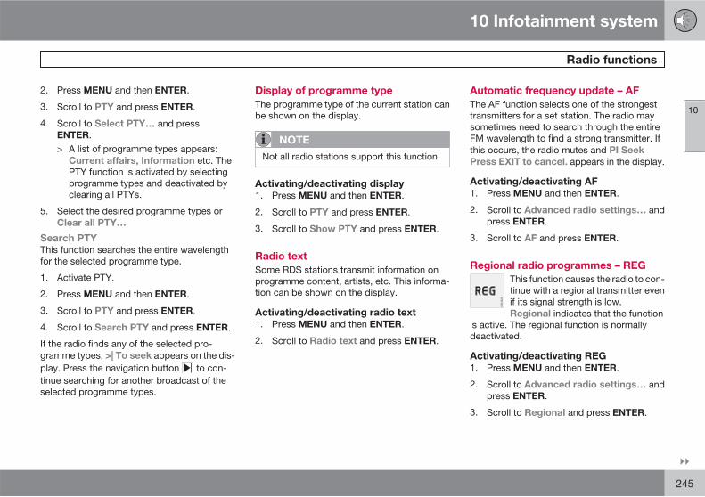
10 Infotainment system
Radio functions
10
��
245
2. Press MENU and then ENTER.
3. Scroll to PTY and press ENTER.
4. Scroll to Select PTY… and pressENTER.> A list of programme types appears:
Current affairs, Information etc. ThePTY function is activated by selectingprogramme types and deactivated byclearing all PTYs.
5. Select the desired programme types orClear all PTY…
Search PTY
This function searches the entire wavelengthfor the selected programme type.
1. Activate PTY.
2. Press MENU and then ENTER.
3. Scroll to PTY and press ENTER.
4. Scroll to Search PTY and press ENTER.
If the radio finds any of the selected pro-gramme types, >| To seek appears on the dis-play. Press the navigation button to con-tinue searching for another broadcast of theselected programme types.
Display of programme type
The programme type of the current station canbe shown on the display.
NOTE
Not all radio stations support this function.
Activating/deactivating display
1. Press MENU and then ENTER.
2. Scroll to PTY and press ENTER.
3. Scroll to Show PTY and press ENTER.
Radio text
Some RDS stations transmit information onprogramme content, artists, etc. This informa-tion can be shown on the display.
Activating/deactivating radio text
1. Press MENU and then ENTER.
2. Scroll to Radio text and press ENTER.
Automatic frequency update – AF
The AF function selects one of the strongesttransmitters for a set station. The radio maysometimes need to search through the entireFM wavelength to find a strong transmitter. Ifthis occurs, the radio mutes and PI Seek
Press EXIT to cancel. appears in the display.
Activating/deactivating AF
1. Press MENU and then ENTER.
2. Scroll to Advanced radio settings… andpress ENTER.
3. Scroll to AF and press ENTER.
Regional radio programmes – REG
This function causes the radio to con-tinue with a regional transmitter evenif its signal strength is low.Regional indicates that the function
is active. The regional function is normallydeactivated.
G021223
Activating/deactivating REG
1. Press MENU and then ENTER.
2. Scroll to Advanced radio settings… andpress ENTER.
3. Scroll to Regional and press ENTER.
10 Infotainment system
Radio functions
10
246
Enhanced Other Networks – EON
The EON function is especially useful in urbanareas with many regional radio stations. Itallows the distance between the car and theradio station transmitter to determine whenprogramme functions should interrupt the cur-rent audio source.
• Local – interrupts only if the radio stationtransmitter is close.
• Distant – interrupts if the station transmit-ter is far away, even if there is a lot of static.
• Off – no interruption for programmes fromother transmitters.
Activating/deactivating EON
1. Press MENU and then ENTER.
2. Scroll to Advanced radio settings… andpress ENTER.
3. Scroll to EON… and press ENTER.
4. Scroll to Local, Distant or Off and pressENTER.
Resetting RDS functions
Resets all radio settings to the original factorysettings.
1. Press MENU and then ENTER.
2. Scroll to Advanced radio settings… andpress ENTER.
3. Scroll to Reset all… and press ENTER.
Volume control, programme types
The interrupting programme types are heard atthe volume selected for each programme type.If the volume level is adjusted during the pro-gramme interruption, the new level is saveduntil the next programme interruption.
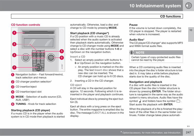
10 Infotainment system
CD functions
10
��
* Option/accessory, for more information, see Introduction. 247
CD function controls
G019807
Navigation button – Fast forward/rewind,track selection and menus
CD changer position selection*
CD insertion/eject
CD insertion/eject slot
MODE - Selection of audio source (CD,AUX, USB*)
TUNING - Knob for track selection
Starting playback (CD player)
If a music CD is in the player when the audiosystem is in CD mode then playback is started
automatically. Otherwise, load a disc andchange to CD mode by pressing MODE.
Start playback (CD changer*)
If a CD position with a music CD is alreadyselected when the audio system is activatedthen playback starts automatically. Otherwisechange to CD changer mode using MODE andselect a disc with the number buttons 1–6 orUp/Down on the navigation button.
Insert a CD
1. Select an empty position with buttons 1–
6 or Up/Down on the navigation button.> An empty position is marked on the dis-
play. The text Insert disc shows that anew disc can be inserted. TheCD changer can hold up to 6 CD discs.
2. Inserting a CD in the CD changer.
CD eject
A CD will stay in the ejected position forapprox. 12 seconds. Following which it is re-inserted in the player and playback continues.
Eject individual discs by pressing the eject but-ton (3).
Eject all discs with a long press on the ejectbutton. The entire magazine is emptied disc bydisc. The message EJECT ALL is shown in thedisplay.
Pause
If the volume is turned down completely, theCD player is stopped. The player is restartedwhen volume is increased.
Audio files*
The CD player/CD changer* also supports MP3and WMA format audio files.
NOTE
Certain types of copy-protected audio filescannot be read by the player.
When a CD containing audio files is insertedinto the player the disc's folder structure is loa-ded in. It may take a while before playbackstarts due to the quality of the disc.
Navigation and playback
If a disc with audio files is inserted in theCD player then the disc's folder structure isshown by pressing ENTER. The folder struc-ture is navigated in the same way as the audiosystem's menu structure. Audio files have thesymbol and folders have the symbol .Start audio file playback with ENTER.
When the playback of a file is finished the play-back of the other files in the same folder con-tinues. Folder change takes place automati-
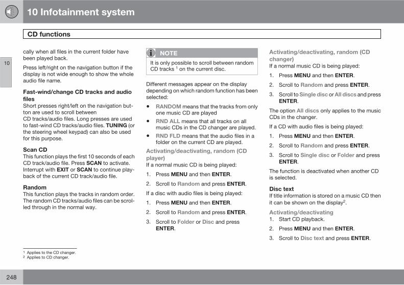
10 Infotainment system
CD functions
10
248
cally when all files in the current folder havebeen played back.
Press left/right on the navigation button if thedisplay is not wide enough to show the wholeaudio file name.
Fast-wind/change CD tracks and audio
files
Short presses right/left on the navigation but-ton are used to scroll betweenCD tracks/audio files. Long presses are usedto fast-wind CD tracks/audio files. TUNING (orthe steering wheel keypad) can also be usedfor this purpose.
Scan CD
This function plays the first 10 seconds of eachCD track/audio file. Press SCAN to activate.Interrupt with EXIT or SCAN to continue play-back of the current CD track/audio file.
Random
This function plays the tracks in random order.The random CD tracks/audio files can be scrol-led through in the normal way.
NOTE
It is only possible to scroll between randomCD tracks 1 on the current disc.
Different messages appear on the displaydepending on which random function has beenselected:
• RANDOM means that the tracks from onlyone music CD are played
• RND ALL means that all tracks on allmusic CDs in the CD changer are played.
• RND FLD means that the audio files in afolder on the current CD are played.
Activating/deactivating, random (CD
player)
If a normal music CD is being played:
1. Press MENU and then ENTER.
2. Scroll to Random and press ENTER.
If a disc with audio files is being played:
1. Press MENU and then ENTER.
2. Scroll to Random and press ENTER.
3. Scroll to Folder or Disc and pressENTER.
Activating/deactivating, random (CD
changer)
If a normal music CD is being played:
1. Press MENU and then ENTER.
2. Scroll to Random and press ENTER.
3. Scroll to Single disc or All discs and pressENTER.
The option All discs only applies to the musicCDs in the changer.
If a CD with audio files is being played:
1. Press MENU and then ENTER.
2. Scroll to Random and press ENTER.
3. Scroll to Single disc or Folder and pressENTER.
The function is deactivated when another CDis selected.
Disc text
If title information is stored on a music CD thenit can be shown on the display2.
Activating/deactivating
1. Start CD playback.
2. Press MENU and then ENTER.
3. Scroll to Disc text and press ENTER.
1 Applies to the CD changer.2 Applies to CD changer.
10 Infotainment system
CD functions
10
249
CDs
Using low quality CD discs could result in pooror non-existent sound.
IMPORTANT
Only use standard discs (12 cm in diameter).Do not use CD discs with adhesive disclabels. The heat in the CD player may causethe label to come off, damaging theCD player.
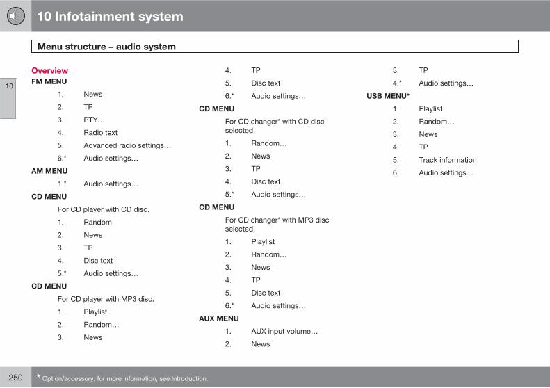
10 Infotainment system
Menu structure – audio system
10
250 * Option/accessory, for more information, see Introduction.
Overview
FM MENU
1. News
2. TP
3. PTY…
4. Radio text
5. Advanced radio settings…
6.* Audio settings…
AM MENU
1.* Audio settings…
CD MENU
For CD player with CD disc.
1. Random
2. News
3. TP
4. Disc text
5.* Audio settings…
CD MENU
For CD player with MP3 disc.
1. Playlist
2. Random…
3. News
4. TP
5. Disc text
6.* Audio settings…
CD MENU
For CD changer* with CD discselected.
1. Random…
2. News
3. TP
4. Disc text
5.* Audio settings…
CD MENU
For CD changer* with MP3 discselected.
1. Playlist
2. Random…
3. News
4. TP
5. Disc text
6.* Audio settings…
AUX MENU
1. AUX input volume…
2. News
3. TP
4.* Audio settings…
USB MENU*
1. Playlist
2. Random…
3. News
4. TP
5. Track information
6. Audio settings…
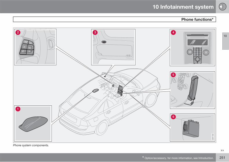
10 Infotainment system
Phone functions*
10
��
* Option/accessory, for more information, see Introduction. 251
Phone system components.
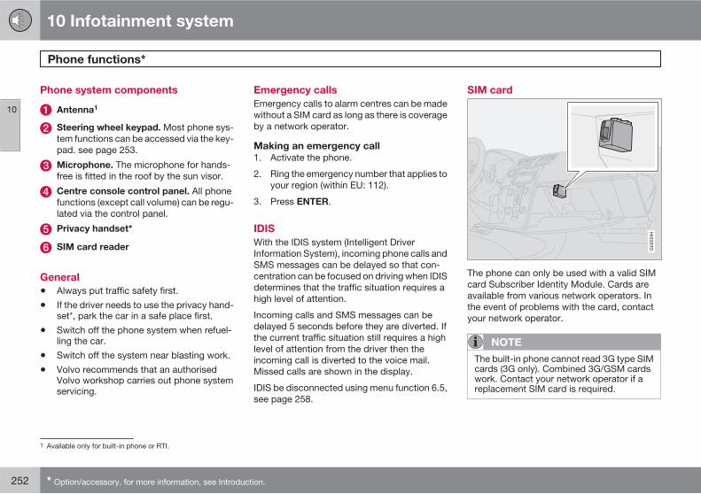
10 Infotainment system
Phone functions*
10
252 * Option/accessory, for more information, see Introduction.
Phone system components
Antenna1
Steering wheel keypad. Most phone sys-tem functions can be accessed via the key-pad. see page 253.
Microphone. The microphone for hands-free is fitted in the roof by the sun visor.
Centre console control panel. All phonefunctions (except call volume) can be regu-lated via the control panel.
Privacy handset*
SIM card reader
General
• Always put traffic safety first.
• If the driver needs to use the privacy hand-set*, park the car in a safe place first.
• Switch off the phone system when refuel-ling the car.
• Switch off the system near blasting work.
• Volvo recommends that an authorisedVolvo workshop carries out phone systemservicing.
Emergency calls
Emergency calls to alarm centres can be madewithout a SIM card as long as there is coverageby a network operator.
Making an emergency call
1. Activate the phone.
2. Ring the emergency number that applies toyour region (within EU: 112).
3. Press ENTER.
IDIS
With the IDIS system (Intelligent DriverInformation System), incoming phone calls andSMS messages can be delayed so that con-centration can be focused on driving when IDISdetermines that the traffic situation requires ahigh level of attention.
Incoming calls and SMS messages can bedelayed 5 seconds before they are diverted. Ifthe current traffic situation still requires a highlevel of attention from the driver then theincoming call is diverted to the voice mail.Missed calls are shown in the display.
IDIS be disconnected using menu function 6.5,see page 258.
SIM card
G020244
The phone can only be used with a valid SIMcard Subscriber Identity Module. Cards areavailable from various network operators. Inthe event of problems with the card, contactyour network operator.
NOTE
The built-in phone cannot read 3G type SIMcards (3G only). Combined 3G/GSM cardswork. Contact your network operator if areplacement SIM card is required.
1 Available only for built-in phone or RTI.
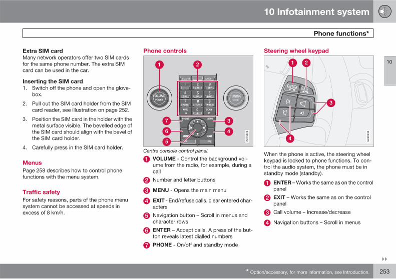
10 Infotainment system
Phone functions*
10
��
* Option/accessory, for more information, see Introduction. 253
Extra SIM card
Many network operators offer two SIM cardsfor the same phone number. The extra SIMcard can be used in the car.
Inserting the SIM card
1. Switch off the phone and open the glove-box.
2. Pull out the SIM card holder from the SIMcard reader, see illustration on page 252.
3. Position the SIM card in the holder with themetal surface visible. The bevelled edge ofthe SIM card should align with the bevel ofthe SIM card holder.
4. Carefully press in the SIM card holder.
Menus
Page 258 describes how to control phonefunctions with the menu system.
Traffic safety
For safety reasons, parts of the phone menusystem cannot be accessed at speeds inexcess of 8 km/h.
Phone controls
G019809
Centre console control panel.
VOLUME - Control the background vol-ume from the radio, for example, during acall
Number and letter buttons
MENU - Opens the main menu
EXIT - End/refuse calls, clear entered char-acters
Navigation button – Scroll in menus andcharacter rows
ENTER – Accept calls. A press of the but-ton reveals latest dialled numbers
PHONE - On/off and standby mode
Steering wheel keypad
G020243
When the phone is active, the steering wheelkeypad is locked to phone functions. To con-trol the audio system, the phone must be instandby mode (standby).
ENTER – Works the same as on the controlpanel
EXIT – Works the same as on the controlpanel
Call volume – Increase/decrease
Navigation buttons – Scroll in menus
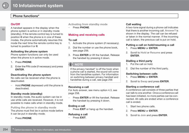
10 Infotainment system
Phone functions*
10
254 * Option/accessory, for more information, see Introduction.
On/Off
A handset appears in the display when thephone system is active or in standby mode(standby). If the remote control key is turned toposition 0 when the phone is in one of thesemodes, the phone automatically resumes thismode the next time the remote control key isturned to position I or II.
Activating the phone system
Phone system functions can only be usedwhen the phone is in active mode.
1. Press PHONE.
2. Enter the PIN code (if necessary) and pressENTER.
Deactivating the phone system
No calls can be received when the phone isdeactivated.
� Hold PHONE depressed until the phone isdeactivated.
Standby mode (standby)
In standby mode, the audio system can be inuse while calls are received. However, it is notpossible to make calls when in standby mode.
Putting the phone in standby mode
The phone must first be in active mode beforeit can be put in standby mode.
� Press PHONE.
Activating from standby mode
� Press PHONE.
Making and receiving calls
To call
1. Activate the phone system (if necessary).
2. Dial the number or use the phone book,see page 256.
3. Press ENTER or lift the handset. Releasethe handset by pressing it down.
NOTE
If the privacy handset* is off the hook whena phone call is started, the sound will comefrom the handsfree system. For informationon switching between privacy handset andhandsfree during a call, see page 256
Receiving a call
For Auto answer, see menu option 4.3, seepage 258.
� Press ENTER or lift the handset. Releasethe handset by pressing it down.
Ending a call
� Press EXIT or hang up the handset.
Refusing a call
� Press EXIT.
Call waiting
A two-tone signal during a phone call indicatesthat there is another incoming call. Answer? isshown in the display. The call can be refusedor taken in the normal manner. If the incomingcall is taken, the previous call is put on hold.
Putting a call on hold/resuming a call
1. Press MENU or ENTER.
2. Scroll to Hold or Resume and pressENTER.
Dialling a third party
1. Put the call on hold.
2. Dial the number of the third party.
Switching between calls
1. Press MENU or ENTER.
2. Scroll to Swap and press ENTER.
Starting a conference call
A conference call consists of three parties thatcan talk to one another. Once a conference callhas been initiated, no more parties can be con-nected. All calls are ended when a conferencecall is ended.
1. Start two phone calls.
2. Press MENU or ENTER.
3. Scroll to Join and press ENTER.
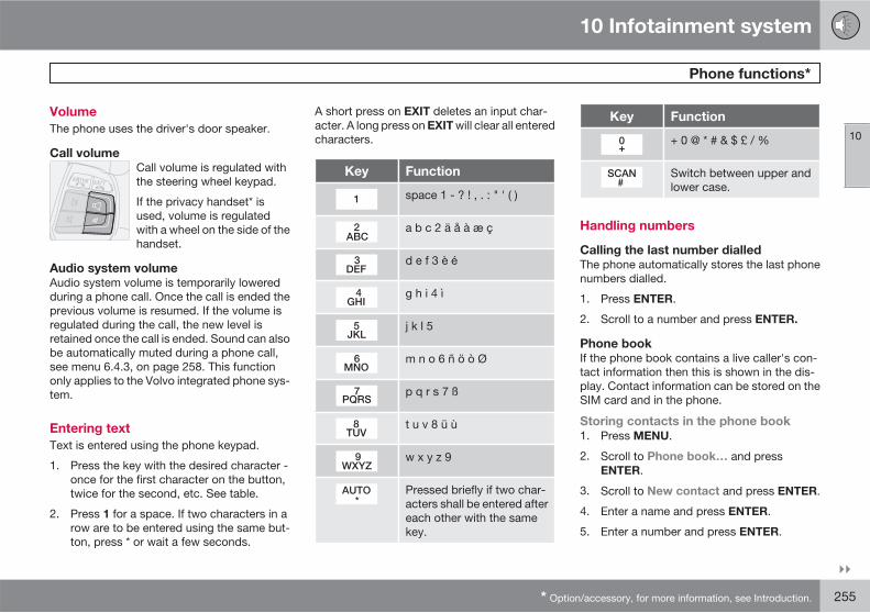
10 Infotainment system
Phone functions*
10
��
* Option/accessory, for more information, see Introduction. 255
Volume
The phone uses the driver's door speaker.
Call volume
Call volume is regulated withthe steering wheel keypad.
If the privacy handset* isused, volume is regulatedwith a wheel on the side of thehandset.
Audio system volume
Audio system volume is temporarily loweredduring a phone call. Once the call is ended theprevious volume is resumed. If the volume isregulated during the call, the new level isretained once the call is ended. Sound can alsobe automatically muted during a phone call,see menu 6.4.3, on page 258. This functiononly applies to the Volvo integrated phone sys-tem.
Entering text
Text is entered using the phone keypad.
1. Press the key with the desired character -once for the first character on the button,twice for the second, etc. See table.
2. Press 1 for a space. If two characters in arow are to be entered using the same but-ton, press * or wait a few seconds.
A short press on EXIT deletes an input char-acter. A long press on EXIT will clear all enteredcharacters.
Key Function
space 1 - ? ! , . : " ' ( )
a b c 2 ä å à æ ç
d e f 3 è é
g h i 4 ì
j k l 5
m n o 6 ñ ö ò Ø
p q r s 7 ß
t u v 8 ü ù
w x y z 9
Pressed briefly if two char-acters shall be entered aftereach other with the samekey.
Key Function
+ 0 @ * # & $ £ / %
Switch between upper andlower case.
Handling numbers
Calling the last number dialled
The phone automatically stores the last phonenumbers dialled.
1. Press ENTER.
2. Scroll to a number and press ENTER.
Phone book
If the phone book contains a live caller's con-tact information then this is shown in the dis-play. Contact information can be stored on theSIM card and in the phone.
Storing contacts in the phone book
1. Press MENU.
2. Scroll to Phone book… and pressENTER.
3. Scroll to New contact and press ENTER.
4. Enter a name and press ENTER.
5. Enter a number and press ENTER.
10 Infotainment system
Phone functions*
10
256 * Option/accessory, for more information, see Introduction.
6. Scroll to SIM card or Phone memory andpress ENTER.
Searching for contacts in the phone book
Use the down arrow of the navigation buttoninstead of MENU for direct access to theSearch menu.
1. Press MENU.
2. Scroll to Phone book… and pressENTER.
3. Scroll to Search and press ENTER.
4. Enter the first few letters of the item andpress ENTER, or simply press ENTER.
5. Scroll to an item and press ENTER.
Copying entries between the SIM card
and Phone book
1. Press MENU.
2. Scroll to Phone book… and pressENTER.
3. Scroll to Copy all… and press ENTER.
4. Scroll to SIM to phone or Phone to SIM
and press ENTER.
Deleting contacts from the phone book
1. Press MENU.
2. Scroll to Phone book… and pressENTER.
3. Scroll to Search and press ENTER.
4. Enter the first few letters of the item andpress ENTER, or simply press ENTER.
5. Scroll to the item to be erased and pressENTER.
6. Scroll to Erase and press ENTER.
Erase all contacts
1. Press MENU.
2. Scroll to Phone book… and pressENTER.
3. Scroll to Erase SIM or Erase phone andpress ENTER.
If required, enter phone code. The factory-setdefault code is 1234.
Speed dial
A keypad button (1–9) can be used as a speeddial number for a contact in the phone book.
1. Press MENU.
2. Scroll to Phone book… and pressENTER.
3. Scroll to Speed dial… and press ENTER.
4. Scroll to Select numbers and pressENTER.
5. Scroll to the digit of the keypad button forthe speed dial number and press ENTER.
6. Enter the first few letters of the item andpress ENTER, or simply press ENTER.
7. Scroll to an item and press ENTER.
8. Hold EXIT depressed to leave the menusystem.
Calling using speed dial
� Briefly press the required keypad button,followed by ENTER.
NOTE
It takes a short time before speed diallingbecomes available after the phone has beenactivated.
To use the speed dial function Speed dial…
must be activated in the Phone book… menu,see page 260.
Calling from the phone book
1. Press MENU.
2. Scroll to Phone book… and pressENTER.> All contacts in the phone book memory
are displayed. The number of contactsdisplayed can be reduced by enteringpart of the contact's name.
3. Scroll to a contact and press ENTER.
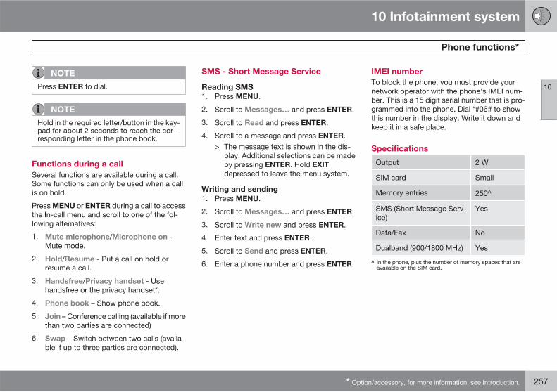
10 Infotainment system
Phone functions*
10
* Option/accessory, for more information, see Introduction. 257
NOTE
Press ENTER to dial.
NOTE
Hold in the required letter/button in the key-pad for about 2 seconds to reach the cor-responding letter in the phone book.
Functions during a call
Several functions are available during a call.Some functions can only be used when a callis on hold.
Press MENU or ENTER during a call to accessthe In-call menu and scroll to one of the fol-lowing alternatives:
1. Mute microphone/Microphone on –Mute mode.
2. Hold/Resume - Put a call on hold orresume a call.
3. Handsfree/Privacy handset - Usehandsfree or the privacy handset*.
4. Phone book – Show phone book.
5. Join – Conference calling (available if morethan two parties are connected)
6. Swap – Switch between two calls (availa-ble if up to three parties are connected).
SMS - Short Message Service
Reading SMS
1. Press MENU.
2. Scroll to Messages… and press ENTER.
3. Scroll to Read and press ENTER.
4. Scroll to a message and press ENTER.> The message text is shown in the dis-
play. Additional selections can be madeby pressing ENTER. Hold EXIT
depressed to leave the menu system.
Writing and sending
1. Press MENU.
2. Scroll to Messages… and press ENTER.
3. Scroll to Write new and press ENTER.
4. Enter text and press ENTER.
5. Scroll to Send and press ENTER.
6. Enter a phone number and press ENTER.
IMEI number
To block the phone, you must provide yournetwork operator with the phone's IMEI num-ber. This is a 15 digit serial number that is pro-grammed into the phone. Dial *#06# to showthis number in the display. Write it down andkeep it in a safe place.
Specifications
Output 2 W
SIM card Small
Memory entries 250A
SMS (Short Message Serv-ice)
Yes
Data/Fax No
Dualband (900/1800 MHz) Yes
A In the phone, plus the number of memory spaces that areavailable on the SIM card.

10 Infotainment system
Menu structure – phone*
10
258 * Option/accessory, for more information, see Introduction.
Phone menu
1. Call register…
1.1. Last 10 missed calls
1.2. Last 10 received calls
1.3. Last 10 dialled calls
1.4. Erase list…
1.4.1. All calls
1.4.2. Missed calls
1.4.3. Received calls
1.4.4. Dialled numbers
1.5. Call duration…
1.5.1. Last call
1.5.2. Call count
1.5.3. Total time
1.5.4. Reset timers
2. Phone book…
2.1. Search
2.2. New contact
2.3. Copy all…
2.3.1. SIM to phone
2.3.2. Phone to SIM
2.4. Speed dial…
2.4.1. Active
2.4.2. Select numbers
2.5. Erase SIM
2.6. Erase phone
2.7. Memory status
3. Messages…
3.1. Read
3.2. Write new
3.3. Message settings…
3.3.1. SMSC number
3.3.2. Validity time…
3.3.3. Message type…
4 Call options…
4.1. Send my number
4.2. Call waiting
4.3. Automatic answer
4.4. Auto re-dial
4.5. Voice mail number
4.6. Diversions…
4.6.1. All calls
4.6.2. When busy
4.6.3. Not answered
4.6.4. Not reachable
4.6.5. Fax calls
4.6.6. Data calls
4.6.7. Cancel all
5. Change phone
5.1. Carphone
5.2. Add phone
5.3–7. Added phones1
NOTE
The menu above only applies to cars withBluetoothTM handsfree.
6. Phone settings…
6.1. Network selection…
6.1.1. Automatic
6.1.2. Manual select
6.2. SIM security…
6.2.1. On
6.2.2. Off
1 A maximum of 5 phones.
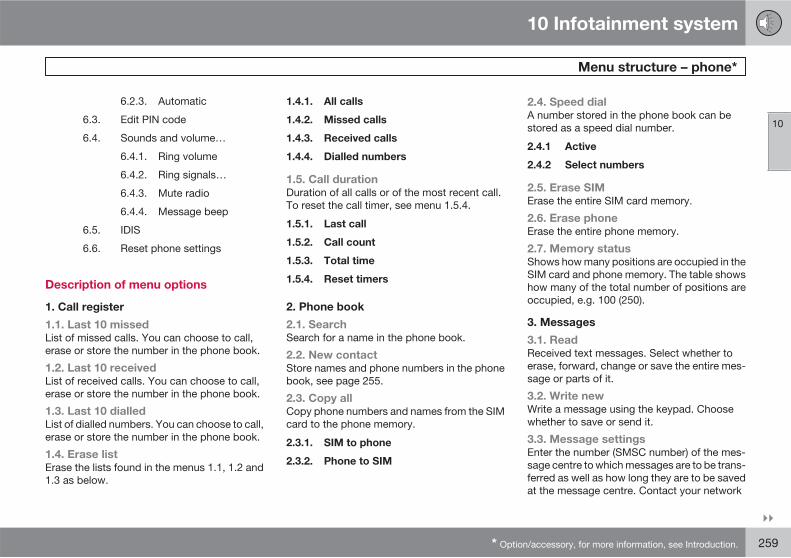
10 Infotainment system
Menu structure – phone*
10
��
* Option/accessory, for more information, see Introduction. 259
6.2.3. Automatic
6.3. Edit PIN code
6.4. Sounds and volume…
6.4.1. Ring volume
6.4.2. Ring signals…
6.4.3. Mute radio
6.4.4. Message beep
6.5. IDIS
6.6. Reset phone settings
Description of menu options
1. Call register
1.1. Last 10 missed
List of missed calls. You can choose to call,erase or store the number in the phone book.
1.2. Last 10 received
List of received calls. You can choose to call,erase or store the number in the phone book.
1.3. Last 10 dialled
List of dialled numbers. You can choose to call,erase or store the number in the phone book.
1.4. Erase list
Erase the lists found in the menus 1.1, 1.2 and1.3 as below.
1.4.1. All calls
1.4.2. Missed calls
1.4.3. Received calls
1.4.4. Dialled numbers
1.5. Call duration
Duration of all calls or of the most recent call.To reset the call timer, see menu 1.5.4.
1.5.1. Last call
1.5.2. Call count
1.5.3. Total time
1.5.4. Reset timers
2. Phone book
2.1. Search
Search for a name in the phone book.
2.2. New contact
Store names and phone numbers in the phonebook, see page 255.
2.3. Copy all
Copy phone numbers and names from the SIMcard to the phone memory.
2.3.1. SIM to phone
2.3.2. Phone to SIM
2.4. Speed dial
A number stored in the phone book can bestored as a speed dial number.
2.4.1 Active
2.4.2 Select numbers
2.5. Erase SIM
Erase the entire SIM card memory.
2.6. Erase phone
Erase the entire phone memory.
2.7. Memory status
Shows how many positions are occupied in theSIM card and phone memory. The table showshow many of the total number of positions areoccupied, e.g. 100 (250).
3. Messages
3.1. Read
Received text messages. Select whether toerase, forward, change or save the entire mes-sage or parts of it.
3.2. Write new
Write a message using the keypad. Choosewhether to save or send it.
3.3. Message settings
Enter the number (SMSC number) of the mes-sage centre to which messages are to be trans-ferred as well as how long they are to be savedat the message centre. Contact your network
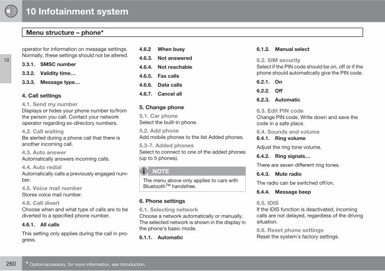
10 Infotainment system
Menu structure – phone*
10
260 * Option/accessory, for more information, see Introduction.
operator for information on message settings.Normally, these settings should not be altered.
3.3.1. SMSC number
3.3.2. Validity time…
3.3.3. Message type…
4. Call settings
4.1. Send my number
Displays or hides your phone number to/fromthe person you call. Contact your networkoperator regarding ex-directory numbers.
4.2. Call waiting
Be alerted during a phone call that there isanother incoming call.
4.3. Auto answer
Automatically answers incoming calls.
4.4. Auto redial
Automatically calls a previously engaged num-ber.
4.5. Voice mail number
Stores voice mail number.
4.6. Call divert
Choose when and what type of calls are to bediverted to a specified phone number.
4.6.1. All calls
This setting only applies during the call in pro-gress.
4.6.2 When busy
4.6.3. Not answered
4.6.4. Not reachable
4.6.5. Fax calls
4.6.6. Data calls
4.6.7. Cancel all
5. Change phone
5.1. Car phone
Select the built-in phone.
5.2. Add phone
Add mobile phones to the list Added phones.
5.3-7. Added phones
Select to connect to one of the added phones(up to 5 phones).
NOTE
The menu above only applies to cars withBluetoothTM handsfree.
6. Phone settings
6.1. Selecting network
Choose a network automatically or manually.The selected network is shown in the display inthe phone's basic mode.
6.1.1. Automatic
6.1.2. Manual select
6.2. SIM security
Select if the PIN code should be on, off or if thephone should automatically give the PIN code.
6.2.1. On
6.2.2. Off
6.2.3. Automatic
6.3. Edit PIN code
Change PIN code. Write down and save thecode in a safe place.
6.4. Sounds and volume
6.4.1. Ring volume
Adjust the ring tone volume.
6.4.2. Ring signals…
There are seven different ring tones.
6.4.3. Mute radio
The radio can be switched off/on.
6.4.4. Message beep
6.5. IDIS
If the IDIS function is deactivated, incomingcalls are not delayed, regardless of the drivingsituation.
6.6. Reset phone settings
Reset the system's factory settings.
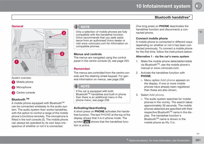
10 Infotainment system
Bluetooth handsfree*
10
��
* Option/accessory, for more information, see Introduction. 261
General
System overview.
Mobile phone
Microphone
Centre console
Bluetooth TM
A mobile phone equipped with BluetoothTM
can be connected wirelessly to the audio sys-tem. The audio system then works handsfree,with the option to control a range of the mobilephone's functions remotely. The microphone isfitted in the roof console (2). The mobile phonecan always be operated by its own keys irre-spective of whether or not it is connected.
NOTE
Only a selection of mobile phones are fullycompatible with the handsfree function.Volvo recommends that you seek assis-tance from an authorised Volvo dealer orvisit www.volvocars.com for information oncompatible phones.
Menus and controls
The menus are navigated using the controlpanel in the centre console (3), see page 253.
Remember
The menus are controlled from the centre con-sole and the steering wheel keypad. For gen-eral information on menus, see page 258.
NOTE
If the car is equipped with bothBluetoothTM handsfree and built-in phonethen there is an additional menu in thephone menu, see page 258.
Activating/deactivating
A short press on PHONE activates the hands-free function. The text PHONE at the top of thedisplay shows that it is in phone mode. Thesymbol shows that the handsfree func-tion is active.
One long press on PHONE deactivates thehandsfree function and disconnects a con-nected phone.
Connect mobile phone
A mobile phone is connected in different waysdepending on whether or not it has been con-nected previously. To connect a mobile phonefor the first time, follow the instructions below:
Alternative 1 - via the car's menu system
1. Make the mobile phone detectable/visiblevia BluetoothTM, see the mobile phone'smanual or www.volvocars.com.
2. Activate the handsfree function withPHONE.> Menu option Add phone appears on
the display. If one or more mobilephones have already been registeredthen these are also shown.
3. Select Add phone.> The audio system searches for mobile
phones in the vicinity. The search takesapproximately 30 seconds. The mobilephones detected are specified with theirrespective BluetoothTM name in the dis-play. The handsfree function'sBluetoothTM name is shown in themobile phone as My Car.
10 Infotainment system
Bluetooth handsfree*
10
262 * Option/accessory, for more information, see Introduction.
4. Choose one of the mobile phones in theaudio system display.
5. Enter the number series shown in the audiosystem display via the mobile phone key-pad.
Alternative 2 - via the phone's menu system
1. Activate the handsfree function withPHONE. If there is a phone connected,disconnect the connected phone.
2. Search with the phone's BluetoothTM, seethe mobile phone's manual.
3. Select My Car in the list of units detectedin your mobile phone.
4. Enter the PIN code '1234' into the mobilephone when prompted for the PIN code.
5. Select to connect to My Car from themobile phone.
The mobile phone is registered and connectedautomatically to the audio system while the textSynchronising appears on the display. Formore information on how mobile phones areregistered, see page 263.
When the connection is established the symbol is shown and the mobile phone's
BluetoothTM name is shown in the display. Now
the mobile phone can be controlled from theaudio system.
To call
1. Make sure that the text PHONE is shownat the top of the display and that the symbol is visible.
2. Dial the number or use the phone book,see page 264.
3. Press ENTER.
The call is interrupted with EXIT.
Disconnecting the mobile phone
Automatic disconnection takes place if themobile phone moves out of the audio system'srange. For more information on connection,see page 263.
Manual disconnection takes place by deacti-vating the handsfree function with one longpress on PHONE. The handsfree function isalso deactivated when the engine is switchedoff or when a door is opened1.
When the mobile phone has been discon-nected an ongoing call can be continued withthe mobile phone's built-in microphone andspeaker.
NOTE
Some mobile phones require that thechangeover from handsfree is confirmedfrom the phone's keypad.
Making and receiving calls
Incoming call
Calls are accepted with ENTER even if theaudio system is in CD or FM mode for example.Refuse or end with EXIT.
Auto answer
The automatic answer function means thatcalls are accepted automatically. Activate/deactivate under Phone Menu… Call
options… Automatic answer.
In-call menu
Press MENU or ENTER during an ongoing callto access the following functions:
• Mute microphone - audio system micro-phone is muted.
• Transfer call to mobile - the call is trans-ferred to the mobile phone.
1 Applies to Keyless Drive.
10 Infotainment system
Bluetooth handsfree*
10
��
* Option/accessory, for more information, see Introduction. 263
NOTE
With certain mobile phones the connectionis terminated when the privacy function isused. This is normal. The handsfree functionasks if you want to reconnect.
• Phone book – searching in the phonebook.
NOTE
A new call cannot be started during anongoing call.
Audio settings
Call volume
Call volume can be adjusted during calls. Usethe steering wheel keypad.
Audio system volume
In phone mode (PHONE) the audio system vol-ume can be adjusted as usual with VOLUME.
The audio source can be automatically mutedfor incoming calls under Phone Menu…
Phone settings… Sounds and volume…
Mute radio.
Ring volume
Go to Phone Menu… Phone settings…
Sounds and volume… Ring volume
and adjust with / on the navigation but-ton.
Ring signals
The handsfree function has integrated ring sig-nals that can be selected under Phone
Menu… Phone settings… Sounds and
volume… Ring signals… Ring signal 1
etc.
NOTE
The connected mobile phone's ring signal isnot deactivated when one of the handsfreesystem's integrated signals is used.
In order to select the connected phone's ringsignal2, go to Phone Menu… Phone
settings… Sounds and volume… Ring
signals… Use mobile phone signal.
More on registering and connecting
A maximum of five mobile phones can be reg-istered. Registration is performed once perphone. After registration the mobile phone is inthe list of added phones. Not more than onemobile phone can be connected at a time.Phones can be deregistered under Phone
Menu… Bluetooth… Remove phone.
Automatic connection
When the handsfree function is active and thelast mobile phone connected is in range it isconnected automatically. When the audio sys-tem searches for the last phone connected itsname is shown in the display. To change overto manual connection of another phone, pressEXIT.
Manual connection
If you want to connect a mobile phone otherthan the last connected or change the con-nected mobile phone, proceed as follows:
Set the audio system in phone mode(PHONE) and follow the instructions on thedisplay or change the connected mobile phoneby using the menu system as described below.
The menu structure is available in two variantsdepending on whether the car only has
2 Not supported by all mobile phones.
10 Infotainment system
Bluetooth handsfree*
10
264 * Option/accessory, for more information, see Introduction.
BluetoothTM or if the car also has a built-inphone.
• For cars with only BluetoothTM the connec-tion is made under Phone Menu…
Bluetooth… Change phone Add
phone or select one of the previously con-nected phones.
• For cars with built-in phone andBluetoothTM the connection is made underPhone Menu… Change phone Add
phone or select one of the previously con-nected phones.
Phonebook
All use of the phone book presupposes that thetext PHONE is shown at the top of the displayand that the symbol is visible.
The audio system stores a copy of the phonebook from each registered mobile phone. Thephone book is copied automatically to theaudio system during each connection. Deacti-vate the function under Phone settings…
Synchronise phone book. Searching for con-tacts is only performed in the connectedmobile phone's phone book.
NOTE
If the mobile phone does not support copy-ing of the phone book then List is empty isshown when copying is finished.
If the phone book contains a ringing caller'scontact information then this is shown in thedisplay.
Searching for contacts
The easiest way to search in the phone book iswith long presses on the keys 2–9. This startsa search in the phone book based on the key'sfirst letter.
The phone book can also be reached with / on the navigation button or with / on
the steering wheel keypad. The search can alsobe performed from the phone book's Searchmenu under Phone book… Search:
1. Enter the first few letters of the contact andpress ENTER. Or simply press ENTER.
2. Scroll to a contact and press ENTER tocall.
Voice recognition
The mobile phone's voice recognition functionfor dialling can be used by holding in ENTER.
NOTE
Only a selection of mobile phones are fullycompatible with the voice recognition func-tion. Volvo recommends that you contact anauthorised Volvo dealer or visitwww.volvocars.com for information oncompatible phones.
Voice mail number
The number to the voice mail is changed underCall options… Voice mail number. If nonumber is stored then this menu is reachedwith one long press on 1. Press 1 for a long timeto use the stored number.
Call lists
The call lists are copied to the handsfree func-tion at each new connection and are thenupdated during the connection. Press ENTER
to show the last dialled. Other call lists areavailable under Call register….
NOTE
Certain mobile phones show a list of the lastdialled calls in reverse order.
Inputting text
Input text using the keypad in the centre con-sole. Press once for the key's first character,
10 Infotainment system
Bluetooth handsfree*
10
��
* Option/accessory, for more information, see Introduction. 265
twice for the second etc. Continue pressing formore characters, see the table on page 255.
A short press on EXIT deletes an input char-acter. One long press on EXIT clears all inputcharacters. / on the navigation buttonscrolls between the characters.
Menu structure - BluetoothTM
handsfree
NOTE
The menu for BluetoothTM handsfree isavailable in two variants. For cars with onlyBluetoothTM handsfree and for cars withbuilt-in phone and BluetoothTM handsfree.
1. Call register…
1.1. Last 10 missed calls
1.2. Last 10 received calls
1.3. Last 10 dialled calls
2. Phone book…
2.1. Search
2.2. Copy fr. mobile phone
3. Bluetooth…
3.1. Change phone
3.1.1. Add phone
3.1.2–6.Added phones3
3.2. Remove phone
3.3. Connect fr. mobile phone
3.4. Car Bluetooth info
4. Call options…
4.1. Automatic answer
4.2. Voice mail number
5. Phone settings…
5.1. Sounds and volume…
5.1.1. Ring volume
5.1.2. Ring signals…
5.1.3. Mute radio
5.2. Synchronise phone book
Menu structure - BluetoothTM
handsfree with built-in phone
1. Call register…
1.1. Last 10 missed calls
1.2. Last 10 received calls
1.3. Last 10 dialled calls
2. Phone book…
2.1. Search
2.2. Copy fr. mobile phone
3. Bluetooth…
3.1. Remove phone
3.2. Connect fr. mobile phone
3.3. Car Bluetooth info
4. Call options…
4.1. Automatic answer
4.2. Voice mail number
5. Change phone
5.1. Carphone
5.2. Add phone
5.3–7. Added phones 3
3 A maximum of 5 phones.
10 Infotainment system
Bluetooth handsfree*
10
266 * Option/accessory, for more information, see Introduction.
6. Phone settings…
6.1. Sounds and volume…
6.1.1. Ring volume
6.1.2. Ring signals…
6.1.3. Mute radio
6.2. Synchronise phone book
10 Infotainment system
10
267
268
Type designation................................................................................... 270Dimensions and weights....................................................................... 272Engine specifications............................................................................ 275Engine oil............................................................................................... 276Fluids and lubricants............................................................................. 278Fuel....................................................................................................... 280Electrical system................................................................................... 283Type approval....................................................................................... 285Symbols in the display.......................................................................... 286
SPECIF ICATIONS
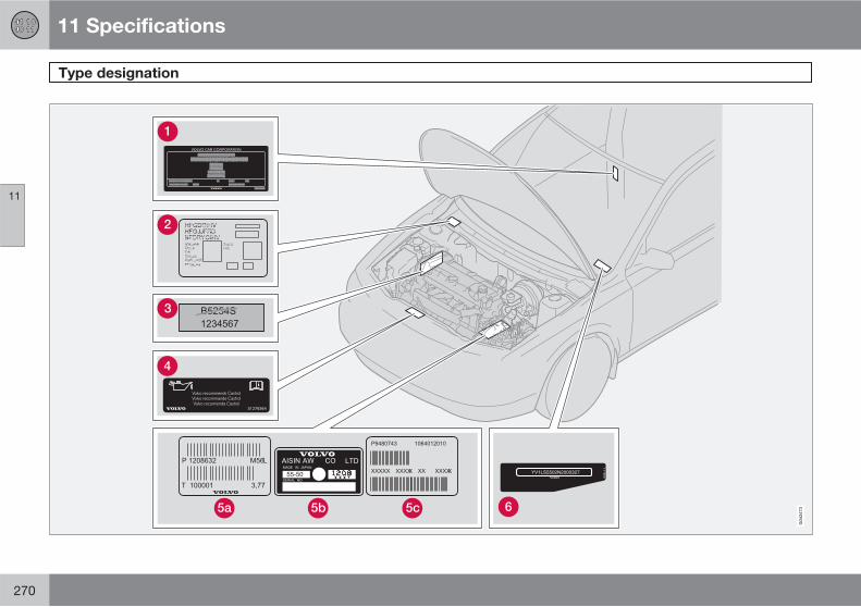
11 Specifications
Type designation
11
270
11 Specifications
Type designation
11
271
Knowing the car's type designation, vehicleidentification and engine numbers can facili-tate all contact with a Volvo dealer regardingthe car and when ordering spare parts andaccessories.
Type designation, vehicle identificationnumber, maximum permissible weights,codes for colour and upholstery and typeapproval number.S40 and V50: The label is visible when theright rear door is opened. C30 and C70:The label is visible when the right door isopened.
Label for parking heater.
Engine code, component and serial num-bers.
Label for engine oil.
Gearbox type designation and serial num-ber:
manual gearbox
, automatic gearbox
VIN number (type and model year desig-nation plus chassis number).
Further information on the car is presented inthe registration document.
NOTE
The labels shown in the owner's manual arenot provided as exact reproductions ofthose in the car. The purpose is to showtheir approximate appearance and locationin the car. The information that applies toyour car in particular is available on the labelin question in your car.
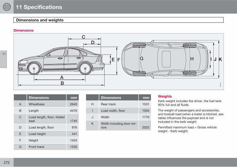
11 Specifications
Dimensions and weights
11
272
Dimensions
Dimensions mm
A Wheelbase 2640
B Length 4476
C Load length, floor, foldedseat 1745
D Load length, floor 976
E Load height 441
F Height 1454
G Front track 1535
Dimensions mm
H Rear track 1531
I Load width, floor 1034
J Width 1770
K Width including door mir-rors 2022
Weights
Kerb weight includes the driver, the fuel tank90% full and all fluids.
The weight of passengers and accessories,and towball load (when a trailer is hitched, seetable) influences the payload and is notincluded in the kerb weight.
Permitted maximum load = Gross vehicleweight - Kerb weight.
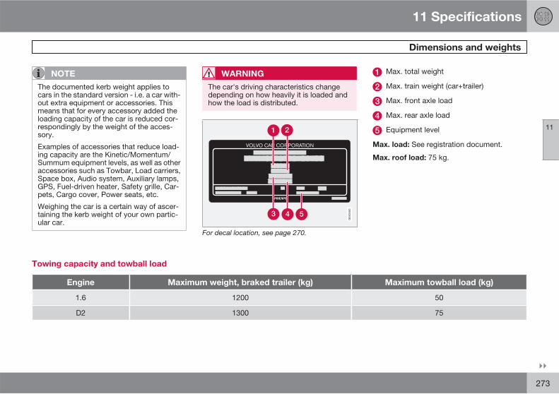
11 Specifications
Dimensions and weights
11
��
273
NOTE
The documented kerb weight applies tocars in the standard version - i.e. a car with-out extra equipment or accessories. Thismeans that for every accessory added theloading capacity of the car is reduced cor-respondingly by the weight of the acces-sory.
Examples of accessories that reduce load-ing capacity are the Kinetic/Momentum/Summum equipment levels, as well as otheraccessories such as Towbar, Load carriers,Space box, Audio system, Auxiliary lamps,GPS, Fuel-driven heater, Safety grille, Car-pets, Cargo cover, Power seats, etc.
Weighing the car is a certain way of ascer-taining the kerb weight of your own partic-ular car.
WARNING
The car's driving characteristics changedepending on how heavily it is loaded andhow the load is distributed.
For decal location, see page 270.
Max. total weight
Max. train weight (car+trailer)
Max. front axle load
Max. rear axle load
Equipment level
Max. load: See registration document.
Max. roof load: 75 kg.
Towing capacity and towball load
Engine Maximum weight, braked trailer (kg) Maximum towball load (kg)
1.6 1200 50
D2 1300 75
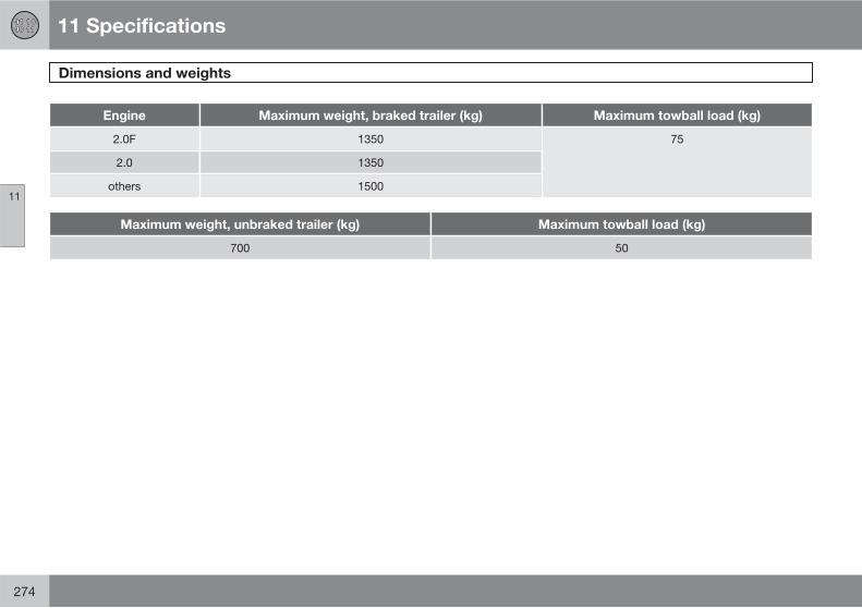
11 Specifications
Dimensions and weights
11
274
Engine Maximum weight, braked trailer (kg) Maximum towball load (kg)
2.0F 1350 75
2.0 1350
others 1500
Maximum weight, unbraked trailer (kg) Maximum towball load (kg)
700 50
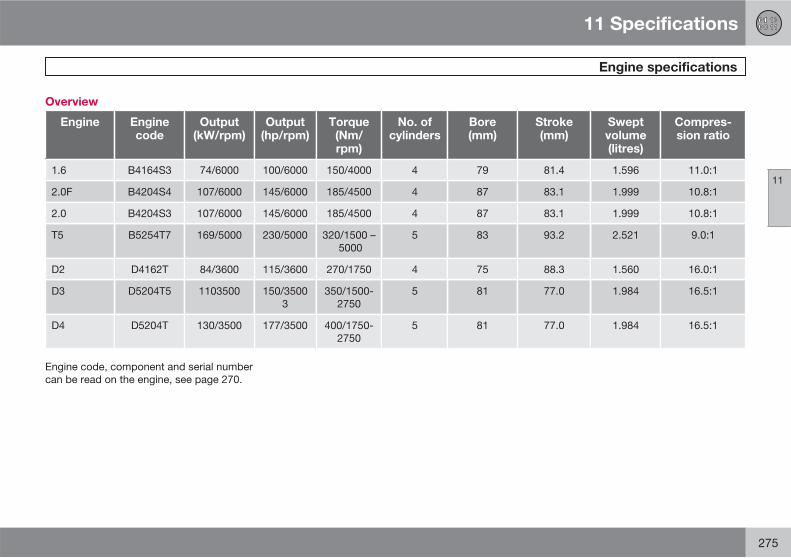
11 Specifications
Engine specifications
11
275
Overview
Engine Enginecode
Output(kW/rpm)
Output(hp/rpm)
Torque(Nm/rpm)
No. ofcylinders
Bore(mm)
Stroke(mm)
Sweptvolume(litres)
Compres-sion ratio
1.6 B4164S3 74/6000 100/6000 150/4000 4 79 81.4 1.596 11.0:1
2.0F B4204S4 107/6000 145/6000 185/4500 4 87 83.1 1.999 10.8:1
2.0 B4204S3 107/6000 145/6000 185/4500 4 87 83.1 1.999 10.8:1
T5 B5254T7 169/5000 230/5000 320/1500 – 5000
5 83 93.2 2.521 9.0:1
D2 D4162T 84/3600 115/3600 270/1750 4 75 88.3 1.560 16.0:1
D3 D5204T5 1103500 150/35003
350/1500-2750
5 81 77.0 1.984 16.5:1
D4 D5204T 130/3500 177/3500 400/1750-2750
5 81 77.0 1.984 16.5:1
Engine code, component and serial numbercan be read on the engine, see page 270.
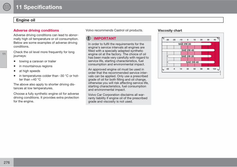
11 Specifications
Engine oil
11
276
Adverse driving conditions
Adverse driving conditions can lead to abnor-mally high oil temperature or oil consumption.Below are some examples of adverse drivingconditions.
Check the oil level more frequently for longjourneys:
• towing a caravan or trailer
• in mountainous regions
• at high speeds
• in temperatures colder than -30 °C or hot-ter than +40 °C
The above also apply to shorter driving dis-tances at low temperatures.
Choose a fully synthetic engine oil for adversedriving conditions. It provides extra protectionfor the engine.
Volvo recommends Castrol oil products.
IMPORTANT
In order to fulfil the requirements for theengine's service intervals all engines arefilled with a specially adapted syntheticengine oil at the factory. The choice of oilhas been made very carefully with regard toservice life, starting characteristics, fuelconsumption and environmental impact.
An approved engine oil must be used inorder that the recommended service inter-vals can be applied. Only use a prescribedgrade of oil for both filling and oil change,otherwise you will risk affecting service life,starting characteristics, fuel consumptionand environmental impact.
Volvo Car Corporation disclaims all war-ranty liability if engine oil of the prescribedgrade and viscosity is not used.
Viscosity chart
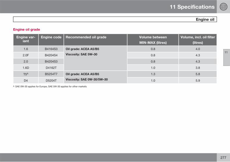
11 Specifications
Engine oil
11
277
Engine oil grade
Engine var-iant
Engine code Recommended oil grade Volume between
MIN-MAX (litres)
Volume, incl. oil filter
(litres)
1.6 B4164S3 Oil grade: ACEA A5/B5
Viscosity: SAE 5W–30
0.8 4.0
2.0F B4204S4 0.8 4.3
2.0 B4204S3 0.8 4.3
1.6D D4162T 1.0 3.8
T5A B5254T7 Oil grade: ACEA A5/B5
Viscosity: SAE 0W-30/5W–30
1.3 5.8
D4 D5204T 1.0 5.9
A SAE 0W-30 applies for Europe, SAE 5W-30 applies for other markets
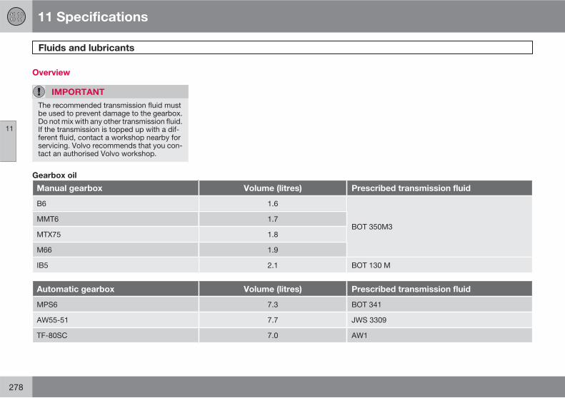
11 Specifications
Fluids and lubricants
11
278
Overview
IMPORTANT
The recommended transmission fluid mustbe used to prevent damage to the gearbox.Do not mix with any other transmission fluid.If the transmission is topped up with a dif-ferent fluid, contact a workshop nearby forservicing. Volvo recommends that you con-tact an authorised Volvo workshop.
Gearbox oil
Manual gearbox Volume (litres) Prescribed transmission fluid
B6 1.6
BOT 350M3MMT6 1.7
MTX75 1.8
M66 1.9
IB5 2.1 BOT 130 M
Automatic gearbox Volume (litres) Prescribed transmission fluid
MPS6 7.3 BOT 341
AW55-51 7.7 JWS 3309
TF-80SC 7.0 AW1
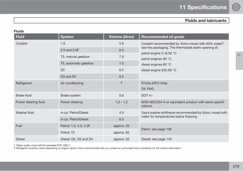
11 Specifications
Fluids and lubricants
11
279
Fluids
Fluid System Volume (litres) Recommended oil grade
Coolant 1.6 5.8 Coolant recommended by Volvo mixed with 50% waterA,see the packaging. The thermostat starts opening at:
petrol engine (1.6) 82 °C
petrol engines 90 °C,
diesel engines 82 °C
diesel engine (D2) 83 °C
2.0 and 2.0F 6.5
T5, manual gearbox 7.0
T5, automatic gearbox 7.5
D2 6.2
D3 and D4 8.5
Refrigerant Air conditioning B R134a (HFC134a)
Oil: PAG
Brake fluid Brake system 0.6 DOT 4+
Power steering fluid Power steering 1,0 – 1,2 WSS M2C204-A or equivalent product with same specifi-cations.
Washer fluid 4-cyl. Petrol/Diesel 4.0 Use a washer antifreeze recommended by Volvo, mixed withwater for temperatures below freezing.
5-cyl. Petrol/Diesel 6.5
Fuel Petrol: 1.6, 2.0, 2.0F approx. 55Petrol: see page 139
Petrol: T5 approx. 62
Diesel Diesel: D2, D3 and D4 approx. 52 Diesel: see page 140
A Water quality must fulfil the standard STD 1285.1.B Refrigerant quantity varies depending on engine variant. Volvo recommends that you contact an authorised Volvo workshop for the correct information.
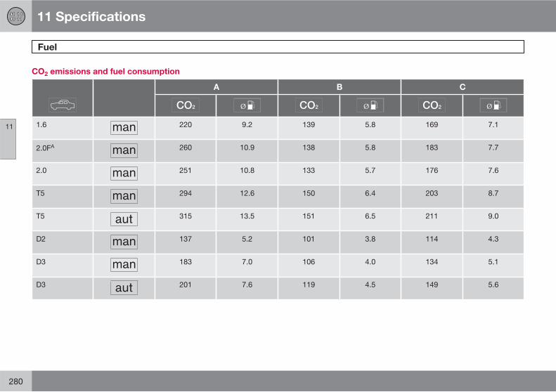
11 Specifications
Fuel
11
280
CO2 emissions and fuel consumption
A B C
1.6 220 9.2 139 5.8 169 7.1
2.0FA 260 10.9 138 5.8 183 7.7
2.0 251 10.8 133 5.7 176 7.6
T5 294 12.6 150 6.4 203 8.7
T5 315 13.5 151 6.5 211 9.0
D2 137 5.2 101 3.8 114 4.3
D3 183 7.0 106 4.0 134 5.1
D3 201 7.6 119 4.5 149 5.6
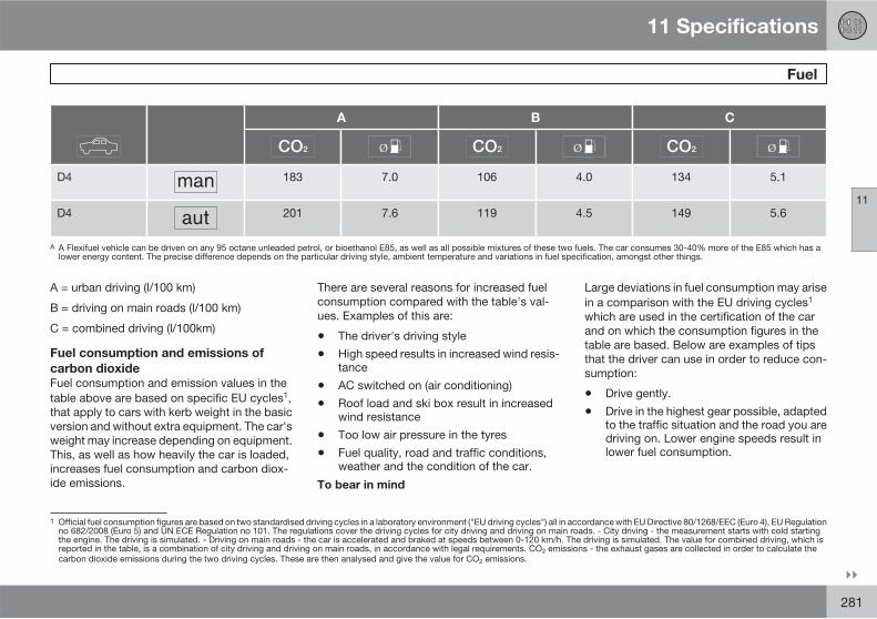
11 Specifications
Fuel
11
��
281
A B C
D4 183 7.0 106 4.0 134 5.1
D4 201 7.6 119 4.5 149 5.6
A A Flexifuel vehicle can be driven on any 95 octane unleaded petrol, or bioethanol E85, as well as all possible mixtures of these two fuels. The car consumes 30-40% more of the E85 which has alower energy content. The precise difference depends on the particular driving style, ambient temperature and variations in fuel specification, amongst other things.
A = urban driving (l/100 km)
B = driving on main roads (l/100 km)
C = combined driving (l/100km)
Fuel consumption and emissions of
carbon dioxide
Fuel consumption and emission values in thetable above are based on specific EU cycles1,that apply to cars with kerb weight in the basicversion and without extra equipment. The car'sweight may increase depending on equipment.This, as well as how heavily the car is loaded,increases fuel consumption and carbon diox-ide emissions.
There are several reasons for increased fuelconsumption compared with the table's val-ues. Examples of this are:
• The driver's driving style
• High speed results in increased wind resis-tance
• AC switched on (air conditioning)
• Roof load and ski box result in increasedwind resistance
• Too low air pressure in the tyres
• Fuel quality, road and traffic conditions,weather and the condition of the car.
To bear in mind
Large deviations in fuel consumption may arisein a comparison with the EU driving cycles1
which are used in the certification of the carand on which the consumption figures in thetable are based. Below are examples of tipsthat the driver can use in order to reduce con-sumption:
• Drive gently.
• Drive in the highest gear possible, adaptedto the traffic situation and the road you aredriving on. Lower engine speeds result inlower fuel consumption.
1 Official fuel consumption figures are based on two standardised driving cycles in a laboratory environment ("EU driving cycles") all in accordance with EU Directive 80/1268/EEC (Euro 4), EU Regulationno 682/2008 (Euro 5) and UN ECE Regulation no 101. The regulations cover the driving cycles for city driving and driving on main roads. - City driving - the measurement starts with cold startingthe engine. The driving is simulated. - Driving on main roads - the car is accelerated and braked at speeds between 0-120 km/h. The driving is simulated. The value for combined driving, which isreported in the table, is a combination of city driving and driving on main roads, in accordance with legal requirements. CO2 emissions - the exhaust gases are collected in order to calculate thecarbon dioxide emissions during the two driving cycles. These are then analysed and give the value for CO2 emissions.
11 Specifications
Fuel
11
282
• Use engine braking to slow down, when itcan take place without risk to other roadusers.
• Avoid letting the engine idle for long peri-ods. Pay attention to local traffic regula-tions. Switch off the engine if stationary forlonger periods, when this can take placewithout endangering other road users.
• If the car is equipped with an electricengine block heater, always use it beforestarting from cold.
• Drive with the correct air pressure in thetyres and check this regularly. Select ECOtyre pressure for best results, see the tyrepressure table on page 187.
• Choice of tyres can affect fuel consump-tion. Information on suitable tyres can begiven by your dealer.
• Extra weight - remove unnecessary itemsfrom the car.
• Remove the space box directly after use.
• Always carry out service and maintenanceon the car in accordance with the instruc-tions in the owner's manual.
Even a combination of some of the above-mentioned examples can result in significantlyimproved consumption.
For further information, please refer to the reg-ulations referred to in accordance with theabove.
WARNING
Never switch off the engine while moving,such as downhill, this deactivates importantsystems such as the power steering andbrake servo.
See page 138 for general information on fuel.
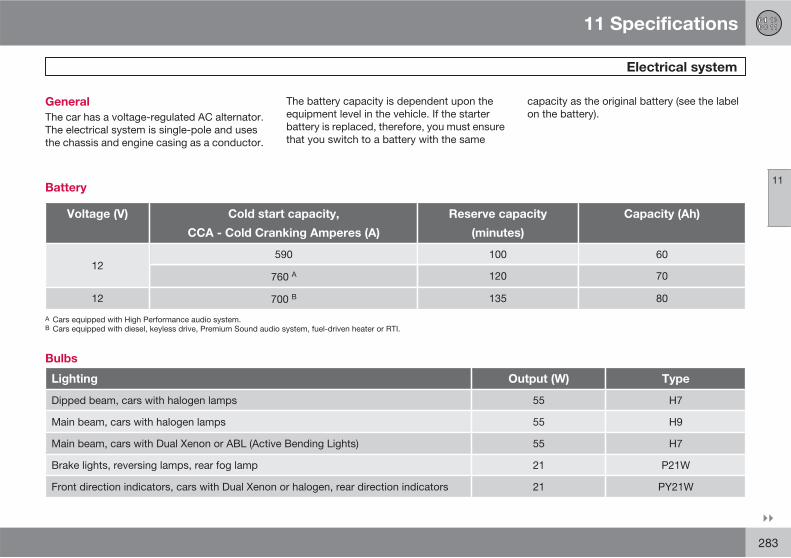
11 Specifications
Electrical system
11
��
283
General
The car has a voltage-regulated AC alternator.The electrical system is single-pole and usesthe chassis and engine casing as a conductor.
The battery capacity is dependent upon theequipment level in the vehicle. If the starterbattery is replaced, therefore, you must ensurethat you switch to a battery with the same
capacity as the original battery (see the labelon the battery).
Battery
Voltage (V) Cold start capacity,
CCA - Cold Cranking Amperes (A)
Reserve capacity
(minutes)
Capacity (Ah)
12590 100 60
760 A 120 70
12 700 B 135 80
A Cars equipped with High Performance audio system.B Cars equipped with diesel, keyless drive, Premium Sound audio system, fuel-driven heater or RTI.
Bulbs
Lighting Output (W) Type
Dipped beam, cars with halogen lamps 55 H7
Main beam, cars with halogen lamps 55 H9
Main beam, cars with Dual Xenon or ABL (Active Bending Lights) 55 H7
Brake lights, reversing lamps, rear fog lamp 21 P21W
Front direction indicators, cars with Dual Xenon or halogen, rear direction indicators 21 PY21W
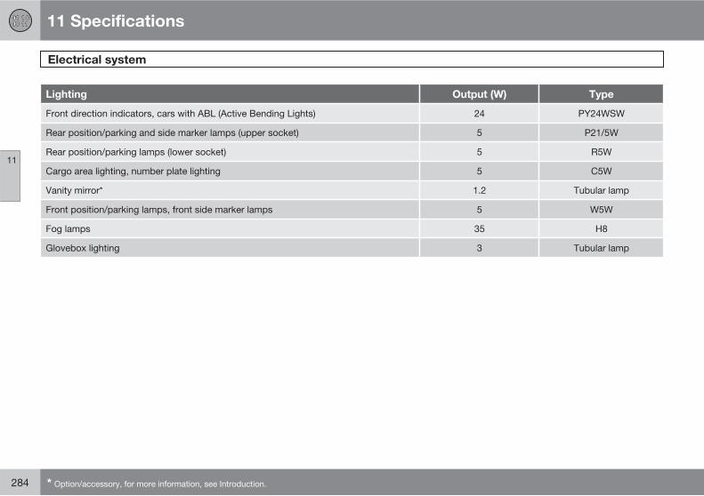
11 Specifications
Electrical system
11
284 * Option/accessory, for more information, see Introduction.
Lighting Output (W) Type
Front direction indicators, cars with ABL (Active Bending Lights) 24 PY24WSW
Rear position/parking and side marker lamps (upper socket) 5 P21/5W
Rear position/parking lamps (lower socket) 5 R5W
Cargo area lighting, number plate lighting 5 C5W
Vanity mirror* 1.2 Tubular lamp
Front position/parking lamps, front side marker lamps 5 W5W
Fog lamps 35 H8
Glovebox lighting 3 Tubular lamp
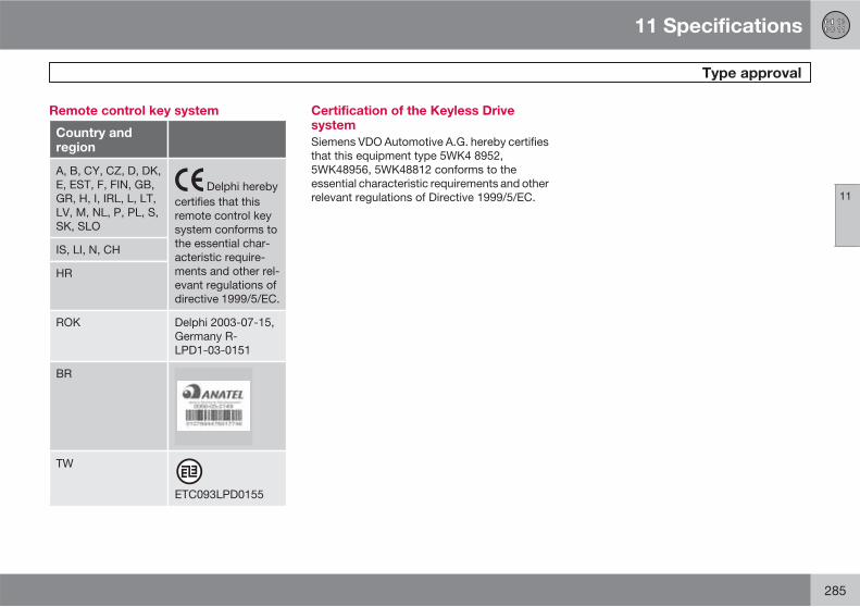
11 Specifications
Type approval
11
285
Remote control key system
Country andregion
A, B, CY, CZ, D, DK,E, EST, F, FIN, GB,GR, H, I, IRL, L, LT,LV, M, NL, P, PL, S,SK, SLO
Delphi herebycertifies that thisremote control keysystem conforms tothe essential char-acteristic require-ments and other rel-evant regulations ofdirective 1999/5/EC.
IS, LI, N, CH
HR
ROK Delphi 2003-07-15,Germany R-LPD1-03-0151
BR
TW
ETC093LPD0155
Certification of the Keyless Drivesystem
Siemens VDO Automotive A.G. hereby certifiesthat this equipment type 5WK4 8952,5WK48956, 5WK48812 conforms to theessential characteristic requirements and otherrelevant regulations of Directive 1999/5/EC.
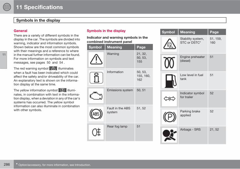
11 Specifications
Symbols in the display
11
286 * Option/accessory, for more information, see Introduction.
General
There are a variety of different symbols in thedisplay in the car. The symbols are divided intowarning, indicator and information symbols.Shown below are the most common symbolswith their meanings and a reference to wherein the manual further information can be found.For more information on symbols and textmessages, see pages 50 and 54 .
The red warning symbol illuminateswhen a fault has been indicated which couldaffect the safety and/or driveability of the car.An explanatory text is shown on the informa-tion display at the same time.
The yellow information symbol illumi-nates, in combination with text in the informa-tion display, when a deviation in any of the car'ssystems has occurred. The yellow symbolinformation can also illuminate in combinationwith other symbols.
Symbols in the display
Indicator and warning symbols in the
combined instrument panel
Symbol Meaning Page
Warning 21, 32,50, 53,155
Information 50, 53,155, 160,162
Emissions system 50, 51
Fault in the ABSsystem
51, 52
Rear fog lamp 51
Symbol Meaning Page
Stability system,STC or DSTC*
51, 159,160
Engine preheater(diesel)
51
Low level in fueltank
51
Indicator symbolfor trailer
52
Parking brakeapplied
52
Airbags - SRS 21, 52
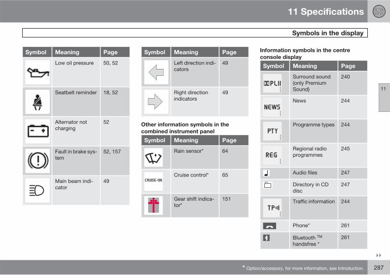
11 Specifications
Symbols in the display
11
��
* Option/accessory, for more information, see Introduction. 287
Symbol Meaning Page
Low oil pressure 50, 52
Seatbelt reminder 18, 52
Alternator notcharging
52
Fault in brake sys-tem
52, 157
Main beam indi-cator
49
Symbol Meaning Page
Left direction indi-cators
49
Right directionindicators
49
Other information symbols in the
combined instrument panel
Symbol Meaning Page
Rain sensor* 64
Cruise control* 65
Gear shift indica-tor*
151
Information symbols in the centre
console display
Symbol Meaning Page
G021216
Surround sound(only PremiumSound)
240
G021221
News 244
G021222
Programme types 244
G021223
Regional radioprogrammes
245
Audio files 247
Directory in CDdisc
247
G021220
Traffic information 244
Phone* 261
Bluetooth TM
handsfree *261
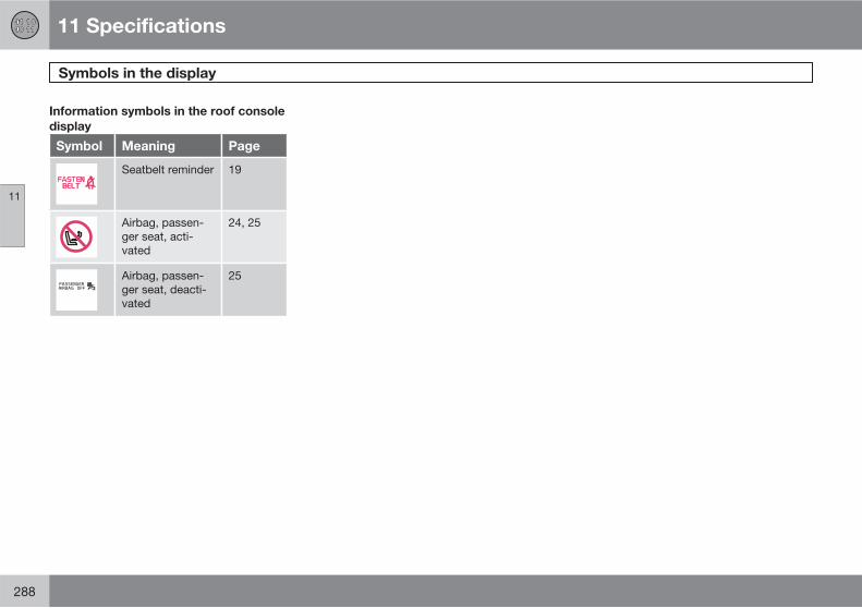
11 Specifications
Symbols in the display
11
288
Information symbols in the roof console
display
Symbol Meaning Page
Seatbelt reminder 19
Airbag, passen-ger seat, acti-vated
24, 25
Airbag, passen-ger seat, deacti-vated
25
11 Specifications
11
289
12 Alphabetical Index
12
290
A
A/Celectronic climate control..................... 93manual climate control................... 88, 89
ABS fault............................................ 51, 157
Active Bending Lights (ABL)...................... 58
Active headlamps...................................... 58
Adaptation............................................... 149
Additional heater (Diesel)........................... 98
Adjusting headlamp pattern.................... 178halogen headlamp.............................. 178
AF – automatic frequency update........... 245
Airbag........................................................ 22activating/deactivating, PACOS........... 24driver's and front passenger side......... 23key switch off........................................ 24
AIRBAG ..................................................... 22
Airbag system............................................ 22
Air conditioning.......................................... 88ECC...................................................... 91general.................................................. 86
Air distribution............................................ 94ECC...................................................... 92
Air distribution, A/C................................... 89
Air quality system, ECC............................. 92
Air vents..................................................... 87
Alarm........................................................ 130alarm indicator.................................... 130arming................................................. 130automatic alarm activation................. 131deactivating a triggered alarm............ 131disarming............................................ 130RDS traffic warning............................. 244reduced alarm level............................ 131testing the alarm system.................... 131
Alcolock................................................... 142
Antenna location, Keyless drive............... 124
Approach light, duration............................ 75setting................................................... 79
Audio, see also Sound............................. 238
Audio volumephone.......................................... 255, 263phone/media player............................ 263programme types............................... 246ring signal, phone............................... 263
Autoclimate control settings........................ 91
AUTOstoring stations................................... 242
Auto climate............................................... 91
Automatic car washes............................. 200
Automatic gearboxmanual gear positions (Geartronic)..... 152towing and recovery........................... 166trailer........................................... 169, 170
Automatic locking.................................... 127
Automatic relocking................................. 126
Autostart.................................................. 146
Auto volume control................................ 241
Auxiliary heater.......................................... 98
Average fuel consumption......................... 61
B
Backrest rear seat, lowering.................... 110
Bag holder............................................... 112
Bass speaker........................................... 239
Battery............................................. 218, 283changing the battery in the remote con-trol key................................................ 125maintenance............................... 209, 218overload.............................................. 137specifications...................................... 283start assistance................................... 168symbols on the battery....................... 218
12 Alphabetical Index
12
291
Bioethanol E85........................................ 139
Blind spot (BLIS)...................................... 163
Blind Spot Information System, BLIS 75, 163
Bluetoothhandsfree............................................ 261mute microphone............................... 262transfer call to mobile......................... 262
Bonnet, opening...................................... 210
Booster cushionfolding up.............................................. 38lowering................................................ 39
Booster cushion, integrated...................... 38
Boot liddriving with open boot lid................... 136locking/unlocking........................ 116, 126
Brake and clutch fluid.............................. 216
Brake light.................................................. 59
Brakesanti-lock braking system, ABS........... 157brake light............................................. 59Emergency Brake Assistance, EBA ... 158emergency brake lights...................... 158handbrake............................................. 69
Brake system........................................... 157
Bulb holderremoval............................................... 223
Bulbschanging............................................. 220
Bulbs, see Lighting.......................... 220, 283
C
Callsfunctions during a call................ 254, 257incoming............................................. 262operation..................................... 254, 262volume in phone................................. 255
Car care................................................... 200
Car care, leather upholstery.................... 202
Cargo area............................................... 112bag holder........................................... 112electrical socket.................................. 112loading................................................ 177load retaining eyelets.......................... 112
Car settings............................................... 79
Car upholstery......................................... 202
Car wash.................................................. 200
Catalytic converter................................... 139recovery.............................................. 166
CD discsstorage compartment......................... 108
CD functions............................................ 247
Checking and topping up the coolant..... 215
Checksfluids and oils...................................... 213
Children..................................................... 33child safety locks.......................... 39, 129child seats and side airbags................. 26location in the car................................. 33location in the car, table....................... 34safety.................................................... 33
Child safety locks.................................... 129
Child seat................................................... 33
Child seats................................................. 33ISOFIX fixture system for child seats. . . 39
Cigarette lighter socketfront seat............................................... 56
Cleaningautomatic car washes......................... 200car wash............................................. 200rims..................................................... 200seatbelts..................................... 202, 203upholstery........................................... 202
12 Alphabetical Index
12
292
Climate controlgeneral.................................................. 86personal preferences............................ 78
Climate control settingsauto....................................................... 91
Clock, adjustment...................................... 78
Clutch fluid, checking & topping up........ 216
Coat hanger............................................. 107
Cold start................................................. 154automatic gearbox.............................. 154
Collisioncrash mode........................................... 32inflatable curtain, IC.............................. 28
Colour code, paint................................... 204
Combined instrument panel...................... 49
Compass................................................... 72calibration............................................. 72setting the zone.................................... 72
Condensation in headlamps.................... 200
Coolant.................................................... 215
Cooling system........................................ 136
Crash, see Collision................................... 32
Cruise control............................................ 65
D
Deadlocks................................................ 127deactivation........................................ 127temporary deactivation....................... 127
Defroster.................................................... 89
Diesel....................................................... 140
Diesel: engine preheater............................ 51
Diesel particle filter.................................. 140
Dipstick, electronic.................................. 214
Direction indicators.................................... 60
Disc text................................................... 248
Disengaging the gear selector inhibitor... 154
Display, messages..................................... 54
Display lighting.......................................... 58
Dolby Surround Pro Logic II............ 237, 240
Door mirrors............................................... 74
Driver's door control panel.................. 48, 70
Drivingcooling system.................................... 136economical......................................... 136in water............................................... 136slippery driving conditions.................. 136with trailer........................................... 169
Driving in water........................................ 136
Driving with a trailertowball load........................................ 272towing capacity.................................. 272
DSTC, see also Stability control system.. 159
DSTC, see also Stability systemsymbol.................................................. 51
During a call, functions............................ 257
E
ECC, electronic climate control................. 87
Economical driving.................................. 136
ECO pressure.......................................... 186table.................................................... 186
Electrical socketcargo area........................................... 112centre console...................................... 56rear seat................................................ 56
Electrical system...................................... 283
Emergency calls...................................... 252
Emergency equipmentwarning triangle.................................. 189
Emergency puncture repair..................... 194
12 Alphabetical Index
12
293
Emission controlfault indicator........................................ 51
Engine block heater................................. 148fuel-driven............................................. 95
Engine compartment............................... 210coolant................................................ 215power steering fluid............................ 216
Engine oil......................................... 213, 276adverse driving conditions.................. 276capacities........................................... 276filter..................................................... 212oil grade.............................................. 276oil pressure........................................... 52
Engine specifications............................... 275
Entry, keyless............................................. 79
Environmental labelling, FSC, owner'smanual....................................................... 15
EON - Enhanced Other Networks............ 246
Equalizer.................................................. 240
Error messages in BLIS........................... 164
Expectant mothers, seatbelt...................... 19
External dimensions................................ 272
F
FanA/C........................................................ 88ECC...................................................... 91
Fast-wind................................................. 248
First aid equipment.................................. 191
Flexifuel.................................................... 148adaptation........................................... 149
Floor mats................................................ 103
Fluids, capacities..................................... 278
Fluids and oils.................................. 212, 278
Fluids and oils, checks, engine compart-ment......................................................... 212
Fluids and oils general............................. 212
Fog lampsrear........................................................ 58
Fog lamps, on/off...................................... 58
Fold down the rear seat backrest ........... 110
Frequency update, automatic.................. 245
Front seats, heated.................................... 89
FSC, environmental labelling..................... 15
FuelCO2 emissions.................................... 280consumption....................................... 280fuel consumption, display..................... 61fuel economy...................................... 186fuel filter.............................................. 140level indicator........................................ 51parking heater....................................... 95refuelling............................................. 138
Fuses....................................................... 226box in the engine compartment.......... 227changing............................................. 226general................................................ 226relay/fuse box in the passenger com-partment............................................. 230
G
Gearboxmanual................................................ 151
Gear selector assistance (GSI - Gear shiftindicator).................................................. 151
Gear selector inhibitor............................. 153
Geartronic................................................ 152
General information on fuel..................... 138
12 Alphabetical Index
12
294
Glovebox................................................. 107locking................................................ 118
Gross vehicle weight............................... 272
GSI - Gear shift indicator......................... 151
H
Handbrake................................................. 69
Hazard warning flashers............................ 68
Headlamp pattern adjustment Active Bending Lights (ABL) .............. 178
Headlamps................................................. 57
Head restraint.......................................... 110
Heatingfront seats....................................... 89, 93rearview and door mirrors.............. 89, 93rear window.................................... 89, 93
High-pressure headlamp washing............. 63
HomeLink ................................................ 81
Home safe lighting............................... 60, 75setting................................................... 79
I
IDIS – Intelligent Driver Information Sys-tem........................................................... 252
Ignition keys............................................. 147
IMEI number............................................ 257
Immobiliser...................................... 116, 147
Inflatable Curtain........................................ 28
Information display.................................... 54
Information on fuel................................... 138
Infotainment systemmenus................................................. 236
Instrument lighting..................................... 58
Instrument overviewleft-hand drive....................................... 44right-hand drive.................................... 46
Integrated booster cushion........................ 38
Interior lighting, see Lighting................... 104
Interior rearview mirror............................... 72automatic dimming............................... 72
Intermittent wiping..................................... 63
iPod , connection................................... 238
ISOFIX fixture system for child seats......... 39
J
Jack......................................................... 190
K
Kerb weight.............................................. 272
Keykeyless lock and ignition system........ 122remote control key.............................. 116
Key blade......................................... 117, 123active locks......................................... 119
Keyless drive............................ 122, 150, 285starting the car.................................... 150
Keyless entry............................................. 79
Keyless start (keyless drive)..................... 122
Keypad in the steering wheel...... 65, 67, 253
Key positions........................................... 146
Kick-downautomatic gearbox.............................. 153
12 Alphabetical Index
12
295
L
Lambda-sond.......................................... 139
Leather upholstery, washing instructions 202
LightingActive Xenon headlamps...................... 58approach light, duration....................... 75automatic lighting............................... 105automatic lighting, dipped beam.......... 57bulbs, specifications........................... 283dipped beam........................................ 57display lighting...................................... 58front fog lamps..................................... 58headlamp levelling................................ 57home safe lighting.......................... 60, 75in passenger compartment................. 104lighting panel, passenger compart-ment...................................................... 57main/dipped beam......................... 57, 60position/parking lamps......................... 57reading lamps..................................... 104rear fog lamp........................................ 58
Lighting, bulb replacement...................... 220cargo area........................................... 224dipped beam...................................... 221direction indicators............................. 222fog lamp.............................................. 223
front.................................................... 220main beam halogen............................ 221number plate lighting.......................... 224parking lamps..................................... 222position lamps.................................... 222rear lamp............................................. 224side marker lamps.............................. 222vanity mirror........................................ 225
Loadinggeneral................................................ 177load capacity...................................... 177load retaining eyelets.......................... 112
Load retaining eyelets.............................. 112
Locking.................................................... 123unlocking............................................ 126
Locking/unlocking................................... 126inside.................................................. 126outside................................................ 126
Lockslocking................................................ 126
Lubricants................................................ 278
Lubricants, capacities.............................. 278
M
Main/dipped beam, see Lightning............. 57
Main beamflashing................................................. 60
Main beam "flash"..................................... 60
Maintenance............................................ 209rustproofing........................................ 205self-maintenance................................ 209
Making calls..................................... 254, 262
Manual gearbox....................................... 151GSI - Gear shift indicator.................... 151towing and recovery........................... 166
Manual gear positions (Geartronic).......... 152
Max. roof load ......................................... 272
Memory function in seats........................ 103
Menusaudio system...................................... 236
Menu structure.......................................... 78media player....................................... 250phone, menu options.......................... 259phone, overview................................. 258
Messages in BLIS.................................... 164
Messages in the information display......... 54
12 Alphabetical Index
12
296
Meters in the combined instrument panelfuel gauge............................................. 49outside temperature gauge.................. 49speedometer......................................... 49tachometer........................................... 49trip meter.............................................. 49
Mistingattending to the windows..................... 86condensation in headlamps............... 200rear window.......................................... 89removing with defroster function.... 89, 92timer function.................................. 89, 92
Mobile phoneconnect............................................... 263handsfree............................................ 261register phone..................................... 261
N
News........................................................ 244
O
Oil, see also Engine oil..................... 213, 276
One-key dial............................................. 256
Owner's manual, environmental labelling.. 15
Oxyhydrogen gas.................................... 168
P
PACOS....................................................... 24
PACOS, switch.......................................... 24
Paintworkcolour code......................................... 204damage and touch-up........................ 204
Parking assistance................................... 161parking assistance sensors................ 162
Parking brake....................................... 52, 69
Parking heaterbattery and fuel..................................... 95general.................................................. 95parking on a hill.................................... 95symbols and display messages............ 96time setting........................................... 97
Passenger compartment filter................... 86
Passenger compartment heaterfuel-driven............................................. 95
Personal preferences................................. 78approach light, duration....................... 79auto blower adjust................................ 78
automatic locking................................. 79doors unlock......................................... 79home safe lighting................................ 79keyless entry......................................... 79lock confirm. light................................. 79recirculation timer................................. 78unlock confirm. light............................. 79
Petrol grade............................................. 139
Phonecalling from the phone book............... 256connect............................................... 263controls............................................... 253entering text........................................ 255handsfree............................................ 261incoming calls..................................... 262making calls........................................ 262on/off.................................................. 254one-key dial........................................ 256phone book......................................... 264phone book, shortcut......................... 264receiving a call.................................... 262register phone..................................... 261standby, standby mode...................... 254traffic safety........................................ 253
Phone bookhandling numbers............................... 255
Phone system.......................................... 252
12 Alphabetical Index
12
297
Pinch protection, sunroof.......................... 77
Polishing.................................................. 201
Power seat............................................... 102
Powershift gearbox.......................... 154, 166
Power steering fluid, checking and toppingup............................................................. 216
Power sunroof........................................... 76
Power windows......................................... 70blocking................................................ 71passenger seat..................................... 71rear seat................................................ 71
Privacy locking......................................... 120
Programme type...................................... 245
PTY – Programme type........................... 244
Puncture, see Tyres......................... 190, 192
Putting calls on hold................................ 254
R
RadioEON.................................................... 246frequency update................................ 245news................................................... 244programme types............................... 243
radio settings...................................... 242radio stations...................................... 242REG.................................................... 245
Radio text................................................ 245
Rain sensor................................................ 64
Random, CD and audio files.................... 248
RDS functions.......................................... 243resetting.............................................. 246
Reading lamps, see Lighting................... 104
Rear seat ................................................. 110
Rearview and door mirrorsautomatic retracting/extending...... 74, 79compass............................................... 72door...................................................... 74electrically retractable........................... 74interior................................................... 72
RecirculationA/C........................................................ 88ECC...................................................... 92
Recommended child seats ....................... 33
Reduced guardsettings................................................. 79
Refrigerant................................................. 86
Refuellingfuel cap............................................... 138fuel filler flap, electrical opening......... 138refuelling............................................. 138
Refusing a call......................................... 254
REG - Regional radio programmes......... 245
Relay/fuse box: see Fuses....................... 226
Remote control........................................ 116replacing the battery........................... 125
Remote control, HomeLink programmable ..................................... 81
Remote control key................................. 147battery replacement............................ 125detachable key blade......................... 117functions............................................. 116
Remote control key system, type appro-val............................................................ 285
Resetting the door mirrors......................... 75
Reverse gear inhibitor.............................. 151
Rimscleaning.............................................. 200
Roof load, max. weight ........................... 272
Rustproofing............................................ 205
12 Alphabetical Index
12
298
S
Safetysafety systems, table............................ 31
ScanCD and audio files.............................. 248radio stations...................................... 243
Seatbeltpregnancy............................................. 19seatbelt tensioner................................. 20
Seatbelt reminder...................................... 19
Seatbelts.................................................... 18
Seatshead restraints, rear............................ 110lowering the rear backrest.................. 110manual setting.................................... 102power seat.......................................... 102
Service programme................................. 208
Side airbags............................................... 26
Side airbag SIPS........................................ 26
SIM card.................................................. 252
SIPS bags.................................................. 26
SMS......................................................... 257read..................................................... 257write.................................................... 257
Soot filter........................................... 54, 141
Soot filter full............................................ 141
Soundaudio settings............................. 238, 239audio source....................................... 238volume................................................ 238
Spare wheel............................................. 190temporary spare......................... 185, 190
Spin control............................................. 159
SRS systemgeneral.................................................. 22
Stability and traction control system....... 159
Stains....................................................... 202
Standby, phone....................................... 254
Start assistance....................................... 168
Starting the engine.................................. 146keyless drive............................... 122, 150
Steering lock............................................ 146
Steering wheelcruise control........................................ 65keypad.................................... 65, 67, 253steering wheel adjustment.................... 68
Stone chips and scratches...................... 204
Storage compartment.............................. 106CD discs............................................. 108
Storage spaces in the passenger compart-ment......................................................... 106
Storing stations, manual and automatic.. 242
Subwoofer............................................... 239
Sun blind.................................................... 74
Sunroof...................................................... 76opening and closing....................... 76, 77pinch protection.................................... 77sunscreen............................................. 77ventilation position................................ 76
Sunscreen, sunroof.................................... 77
Surround.......................................... 237, 240
Symbols................................................... 160indicator symbols........................... 51, 52warning symbols................................... 50
Symbols and display messagesparking heater....................................... 96
T
Tank volume............................................ 278
Technical data, engine............................. 275
12 Alphabetical Index
12
299
Temperatureactual temperature............................... 87passenger compartment, electronic cli-mate control.......................................... 93passenger compartment, manual cli-mate control.......................................... 90
Testing the alarm system......................... 131
TimerA/C........................................................ 89ECC...................................................... 92
Tools........................................................ 190
Total airing function................................. 127
Towbar, see Towing equipment.............. 171
Towing..................................................... 166towing eye.......................................... 167
Towing capacity....................................... 272
Towing equipment................................... 171installation........................................... 173removing............................................. 175specifications...................................... 172
Towing eye.............................................. 167
TP – Traffic information............................ 244
Traffic information.................................... 244
Trailer....................................................... 169cable................................................... 171
Trip computer............................................ 61
Tuning Radio............................................ 242
Type approval, remote control key sys-tem........................................................... 285
Type designation..................................... 270
Tyresdirection of rotation............................ 185driving characteristics......................... 182general................................................ 182maintenance....................................... 182pressure...................................... 186, 187puncture repair................................... 194specifications...................................... 182speed ratings...................................... 182tread wear indicators.......................... 183winter tyres......................................... 185
U
Unlocking......................................... 123, 126settings................................................. 79
USB, connection...................................... 238
V
Ventilation.................................................. 87
Vibration damper..................................... 171
Volumeaudio system...................................... 238auto volume control............................ 241media player....................................... 238
W
Warning lampstability and traction control system. . 159
Warning symbol, airbag system................ 21
Warning triangle....................................... 189
Washer fluid, filling................................... 214
Washersheadlamps............................................ 63washer fluid, filling.............................. 214windscreen........................................... 63
Water and dirt-repellent coating................ 75
Water-repellent surface, cleaning............ 201
Waxing..................................................... 201
Weightskerb weight......................................... 272
12 Alphabetical Index
12
300
Wheelschanging............................................. 192installation........................................... 193removal............................................... 192rims..................................................... 184snow chains........................................ 184spare wheel........................................ 190
Whiplash injury.......................................... 29
WHIPSchild seat/booster cushion................... 29whiplash injury...................................... 29
Windscreen wipers.................................... 63rain sensor............................................ 64
Winter tyres.............................................. 185
Wiper blades............................................ 217cleaning.............................................. 217replacing, windscreen......................... 217


���������������� ������������� ���������������� ���� ������������������������� !� ����©�����"�����#��$���%����� ��%� �