Embed Size (px)
Citation preview
�ANTI-THEFT SYSTEM
�1995 Volvo 850
1995-96 ACCESSORIES & EQUIPMENT Volvo Anti-Theft Systems
850
DESCRIPTION & OPERATION
WARNING: Deactivate air bag system before performing any service operation. For 1995 850, see AIR BAG RESTRAINT SYSTEM, for 1996 850, see AIR BAG RESTRAINT SYSTEM article. Do not apply electrical power to any component on steering column without first deactivating air bag system. Air bag may deploy.
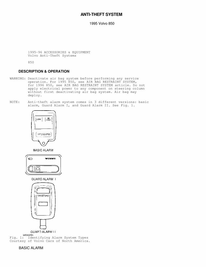
NOTE: Anti-theft alarm system comes in 3 different versions: basic alarm, Guard Alarm I, and Guard Alarm II. See Fig. 1.
Fig. 1: Identifying Alarm System TypesCourtesy of Volvo Cars of North America.
BASIC ALARM
Alarm is activated by LOCK button on remote control or bylocking either front door or trunk using standard door keys. Centrallocking system’s remote control, setting device and lock cylindermicro-switches send signals to central locking relay, which in turnsends a control signal to alarm control module. After 5 seconds, indicator LED goes out and starts flashing.This indicates that alarm has been activated. If any hood, trunk orany door is open when system is activated, LED will not come on. Whendoors, hood and trunk are closed, LED will start flashing to indicatethat all alarm loops have been activated. Alarm is protected bystandard door contacts, contact on hood catch, contact on rear window,and starter inhibitor.
GUARD ALARM I
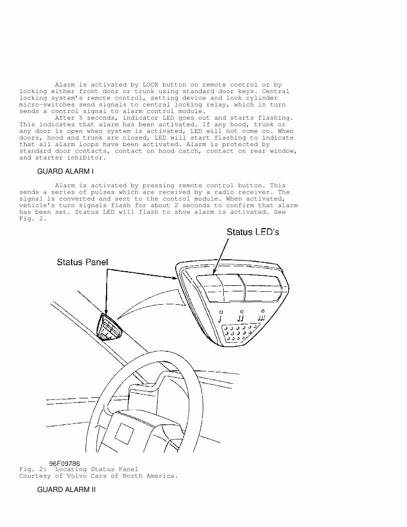
Alarm is activated by pressing remote control button. Thissends a series of pulses which are received by a radio receiver. Thesignal is converted and sent to the control module. When activated,vehicle’s turn signals flash for about 2 seconds to confirm that alarmhas been set. Status LED will flash to show alarm is activated. SeeFig. 2.
Fig. 2: Locating Status PanelCourtesy of Volvo Cars of North America.
GUARD ALARM II
Alarm is activated by pressing large button on remotecontrol. Remote control sends a signal to receiver built into controlmodule. Control module decodes the signal and decides whether stringof pulses is correct. Alarm activation is indicated by single shortflashes from indicator LED. If hood, trunk or any door is open, or ifthere is a fault, indicator LED will light for 5 seconds, then beginflashing.
RECEIVER PROGRAMMING
BASIC ALARM
NOTE: Programming procedures are not available from the manufacturer.
GUARD ALARM I
1) Ensure alarm is deactivated. Close all doors, hood, andtrunk. Turn ignition on. Press function button on status panel untilstatus LED and indicator LED are lit. Release function button. Usingstatus panel function button, advance to unoccupied key code locationI, II or III. An occupied location is indicated by a flashing LED. Anunoccupied location is indicated by a steadily lit LED. If a code isprogrammed into an occupied location, the old code is erased. 2) Select one of 3 locations. Send a code signal within 10seconds using remote control. Alarm will acknowledge an approved codewith brief flashes of status and indicator LED’s before reverting tostandard mode.
GUARD ALARM II
1) Ensure all doors, hood, and trunk are closed. Turnignition on and off at least 5 times in 10 seconds. Indicator LEDshould start to flash. Leave ignition on. Once indicator LED startsflashing, first remote control must be programmed within 15 seconds. 2) Press one button on one remote control. Programming isacknowledged by indicator LED lighting for about 2 seconds. IndicatorLED will then start flashing for 10 seconds. Program other remotecontrol within 10 seconds while indicator LED is flashing. Turnignition off. Test remote controls.
SYSTEM TESTS
SELF TEST
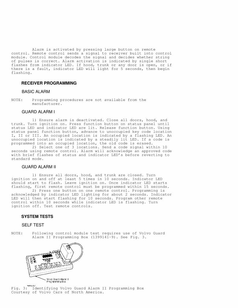
NOTE: Following control module test requires use of Volvo Guard Alarm II Programming Box (1399141-9). See Fig. 3.
Fig. 3: Identifying Volvo Guard Alarm II Programming BoxCourtesy of Volvo Cars of North America.
Guard Alarm II Control Module Press button "C" RUN SELF TEST on programming box. Lowerdisplay line should read TESTING. If control module is okay, lowerline of display will read TEST OK. If control module is faulty,display will read ERRCODE XXX.
FUNCTIONAL TESTS
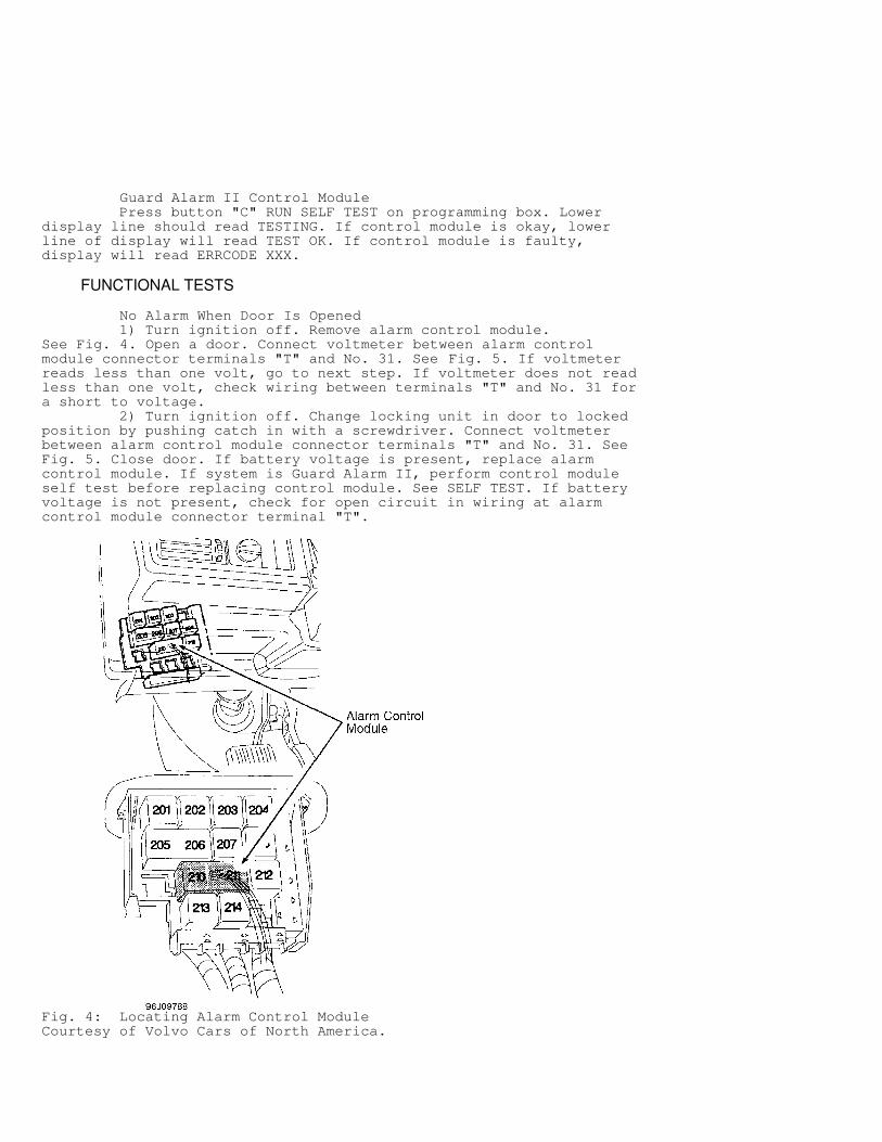
No Alarm When Door Is Opened 1) Turn ignition off. Remove alarm control module.See Fig. 4. Open a door. Connect voltmeter between alarm controlmodule connector terminals "T" and No. 31. See Fig. 5. If voltmeterreads less than one volt, go to next step. If voltmeter does not readless than one volt, check wiring between terminals "T" and No. 31 fora short to voltage. 2) Turn ignition off. Change locking unit in door to lockedposition by pushing catch in with a screwdriver. Connect voltmeterbetween alarm control module connector terminals "T" and No. 31. SeeFig. 5. Close door. If battery voltage is present, replace alarmcontrol module. If system is Guard Alarm II, perform control moduleself test before replacing control module. See SELF TEST. If batteryvoltage is not present, check for open circuit in wiring at alarmcontrol module connector terminal "T".
Fig. 4: Locating Alarm Control ModuleCourtesy of Volvo Cars of North America.
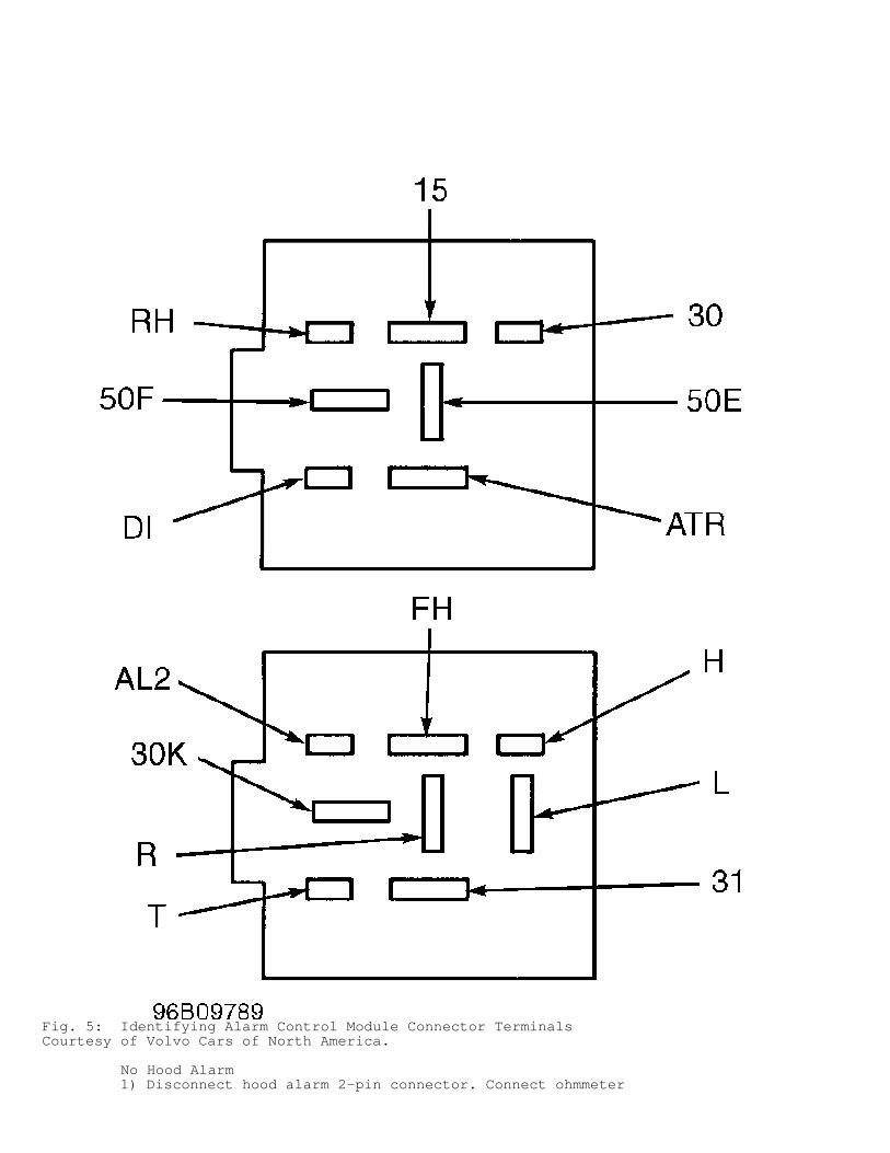
Fig. 5: Identifying Alarm Control Module Connector TerminalsCourtesy of Volvo Cars of North America.
No Hood Alarm 1) Disconnect hood alarm 2-pin connector. Connect ohmmeter
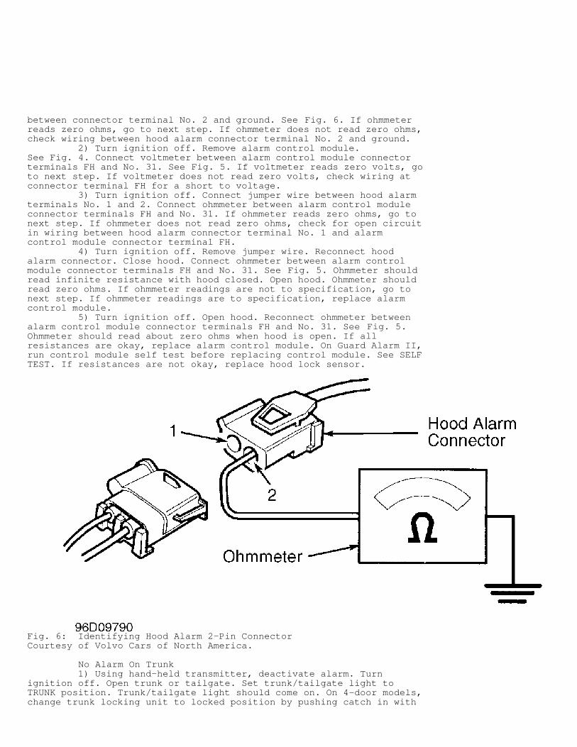
between connector terminal No. 2 and ground. See Fig. 6. If ohmmeterreads zero ohms, go to next step. If ohmmeter does not read zero ohms,check wiring between hood alarm connector terminal No. 2 and ground. 2) Turn ignition off. Remove alarm control module.See Fig. 4. Connect voltmeter between alarm control module connectorterminals FH and No. 31. See Fig. 5. If voltmeter reads zero volts, goto next step. If voltmeter does not read zero volts, check wiring atconnector terminal FH for a short to voltage. 3) Turn ignition off. Connect jumper wire between hood alarmterminals No. 1 and 2. Connect ohmmeter between alarm control moduleconnector terminals FH and No. 31. If ohmmeter reads zero ohms, go tonext step. If ohmmeter does not read zero ohms, check for open circuitin wiring between hood alarm connector terminal No. 1 and alarmcontrol module connector terminal FH. 4) Turn ignition off. Remove jumper wire. Reconnect hoodalarm connector. Close hood. Connect ohmmeter between alarm controlmodule connector terminals FH and No. 31. See Fig. 5. Ohmmeter shouldread infinite resistance with hood closed. Open hood. Ohmmeter shouldread zero ohms. If ohmmeter readings are not to specification, go tonext step. If ohmmeter readings are to specification, replace alarmcontrol module. 5) Turn ignition off. Open hood. Reconnect ohmmeter betweenalarm control module connector terminals FH and No. 31. See Fig. 5.Ohmmeter should read about zero ohms when hood is open. If allresistances are okay, replace alarm control module. On Guard Alarm II,run control module self test before replacing control module. See SELFTEST. If resistances are not okay, replace hood lock sensor.
Fig. 6: Identifying Hood Alarm 2-Pin ConnectorCourtesy of Volvo Cars of North America.
No Alarm On Trunk 1) Using hand-held transmitter, deactivate alarm. Turnignition off. Open trunk or tailgate. Set trunk/tailgate light toTRUNK position. Trunk/tailgate light should come on. On 4-door models,change trunk locking unit to locked position by pushing catch in with
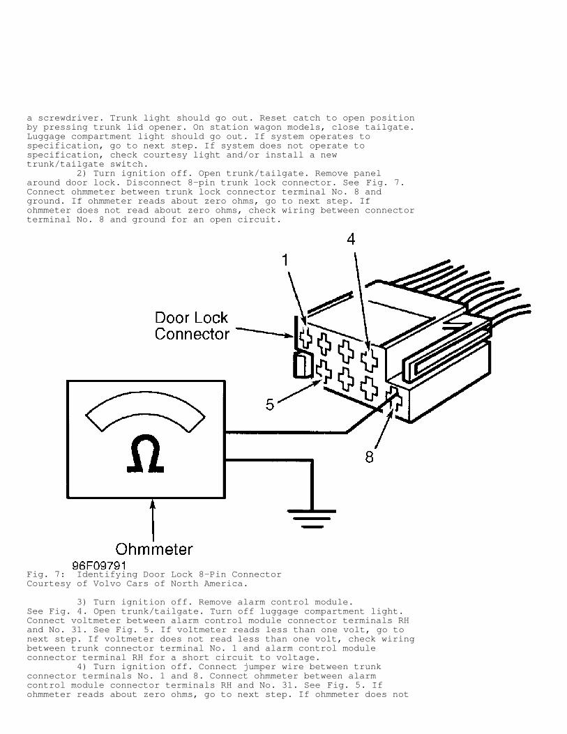
a screwdriver. Trunk light should go out. Reset catch to open positionby pressing trunk lid opener. On station wagon models, close tailgate.Luggage compartment light should go out. If system operates tospecification, go to next step. If system does not operate tospecification, check courtesy light and/or install a newtrunk/tailgate switch. 2) Turn ignition off. Open trunk/tailgate. Remove panelaround door lock. Disconnect 8-pin trunk lock connector. See Fig. 7.Connect ohmmeter between trunk lock connector terminal No. 8 andground. If ohmmeter reads about zero ohms, go to next step. Ifohmmeter does not read about zero ohms, check wiring between connectorterminal No. 8 and ground for an open circuit.
Fig. 7: Identifying Door Lock 8-Pin ConnectorCourtesy of Volvo Cars of North America.
3) Turn ignition off. Remove alarm control module.See Fig. 4. Open trunk/tailgate. Turn off luggage compartment light.Connect voltmeter between alarm control module connector terminals RHand No. 31. See Fig. 5. If voltmeter reads less than one volt, go tonext step. If voltmeter does not read less than one volt, check wiringbetween trunk connector terminal No. 1 and alarm control moduleconnector terminal RH for a short circuit to voltage. 4) Turn ignition off. Connect jumper wire between trunkconnector terminals No. 1 and 8. Connect ohmmeter between alarmcontrol module connector terminals RH and No. 31. See Fig. 5. Ifohmmeter reads about zero ohms, go to next step. If ohmmeter does not
read about zero ohms, check wiring for an open circuit between trunkconnector terminal No. 1 and alarm control module connector terminalRH. 5) Turn ignition off. Remove jumper wire. Reconnect trunkconnector. Close trunk/liftgate. Connect ohmmeter between alarmcontrol module connector terminals RH and No. 31. See Fig. 5. Ohmmetershould read infinite resistance when trunk is closed. Disconnectohmmeter. Turn ignition off. Open trunk/liftgate. Turn off trunklight. 6) Reconnect ohmmeter between alarm control module connectorterminals RH and No. 31. See Fig. 5. If ohmmeter reads about zero ohmswhen trunk/liftgate is open, replace alarm control module. If GuardAlarm II, run control module self test. See SELF TEST. If any readingis incorrect, replace trunk contact.
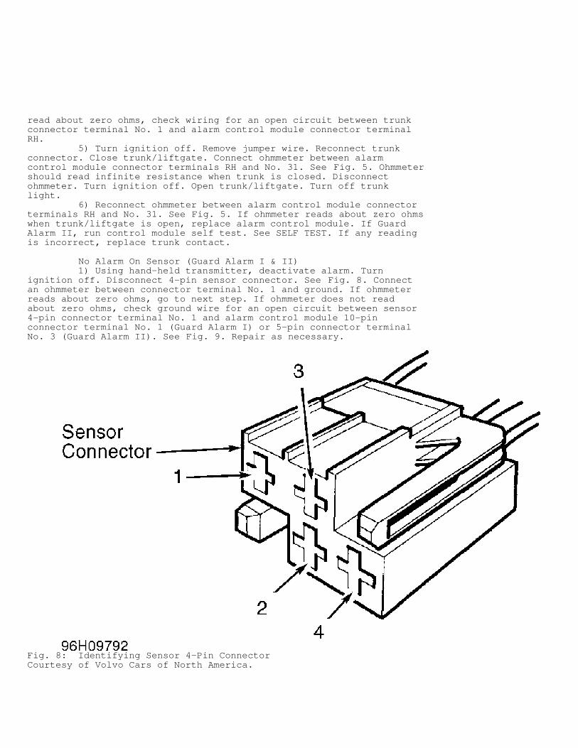
No Alarm On Sensor (Guard Alarm I & II) 1) Using hand-held transmitter, deactivate alarm. Turnignition off. Disconnect 4-pin sensor connector. See Fig. 8. Connectan ohmmeter between connector terminal No. 1 and ground. If ohmmeterreads about zero ohms, go to next step. If ohmmeter does not readabout zero ohms, check ground wire for an open circuit between sensor4-pin connector terminal No. 1 and alarm control module 10-pinconnector terminal No. 1 (Guard Alarm I) or 5-pin connector terminalNo. 3 (Guard Alarm II). See Fig. 9. Repair as necessary.
Fig. 8: Identifying Sensor 4-Pin ConnectorCourtesy of Volvo Cars of North America.
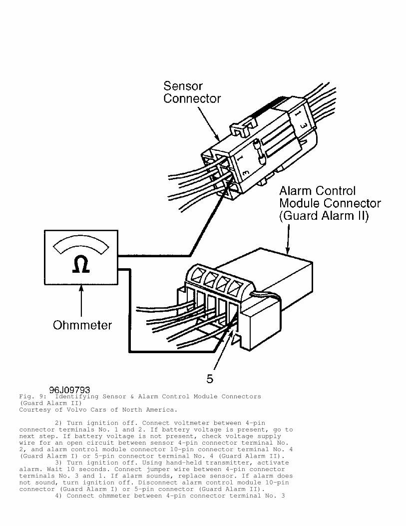
Fig. 9: Identifying Sensor & Alarm Control Module Connectors(Guard Alarm II)Courtesy of Volvo Cars of North America.
2) Turn ignition off. Connect voltmeter between 4-pinconnector terminals No. 1 and 2. If battery voltage is present, go tonext step. If battery voltage is not present, check voltage supplywire for an open circuit between sensor 4-pin connector terminal No.2, and alarm control module connector 10-pin connector terminal No. 4(Guard Alarm I) or 5-pin connector terminal No. 4 (Guard Alarm II). 3) Turn ignition off. Using hand-held transmitter, activatealarm. Wait 10 seconds. Connect jumper wire between 4-pin connectorterminals No. 3 and 1. If alarm sounds, replace sensor. If alarm doesnot sound, turn ignition off. Disconnect alarm control module 10-pinconnector (Guard Alarm I) or 5-pin connector (Guard Alarm II). 4) Connect ohmmeter between 4-pin connector terminal No. 3
and alarm control module connector terminal No. 5. See Fig. 9. Ifohmmeter reads about zero ohms, replace alarm control module. If GuardAlarm II, run control module self test. See SELF TEST. If any readingis incorrect, check wiring for an open circuit between 4-pin connectorterminal No. 3 and alarm control module connector terminal No. 5.
False Alarm 1) Using hand-held transmitter, deactivate alarm. Turnignition off. Remove alarm control module. See Fig. 4. Disconnect allalarm loops (door, trunk, hood, etc.) except ignition. Disconnectfollowing wiring from relay center and insulate with tape orinsulators:
* Door contacts (Yellow/White wire at terminal "T"). * Hood alarm loop (Yellow/Black wire at terminal FH). * Trunk alarm loop (Blue/Brown wire at terminal RH).
2) Disconnect sensor 4-pin connector (Guard Alarm I and II).Turn ignition off. Reinstall alarm control module. Close all doors,hood, and trunk lid. Activate alarm. If alarm continues, check falsealarm at ignition voltage supply circuit.
No Audible Signal When Alarm Is Triggered 1) Using hand-held transmitter, deactivate horn. Turnignition off. Remove alarm control module. See Fig. 4. Connect jumperwire between alarm control module connector terminals "H" and No. 30.See Fig. 5. If horn does not sound, go to next step. If horn sounds,replace alarm control module. If Guard Alarm II, run control moduleself test. See SELF TEST. 2) Turn ignition off. Leave jumper wire connected. Disconnecthorn 2-pin connector. Connect voltmeter between horn connectorterminal No. 1 (Yellow/Red wire) and ground. If battery voltage ispresent, go to next step. If voltage is not present, check wiringbetween alarm control module connector terminal "H" and horn connectorterminal No. 1 for an open circuit. 3) Turn ignition off. Remove jumper wire. Connect ohmmeterbetween horn connector terminal No. 2 (Black wire) and ground. Ifohmmeter reads about zero ohms, replace horn. If ohmmeter does notread about zero ohms, check wiring between horn connector terminal No.2 and ground.
Turn Signal Lights Do Not Flash When Alarm Is Triggered 1) Using hand-held transmitter, deactivate alarm. Turnignition on. Turn left and right turn signal indicators on. If bothindicators flash, go to next step. If both indicators do not flash,check turn signal switch. 2) Turn ignition off. Remove fuse No. 13 from enginecompartment fuse panel. If fuse is okay, go to next step. If fuse isnot okay, check wiring between battery and alarm control moduleconnector terminal No. 30K for a short to ground. 3) Ensure ignition is off. Connect voltmeter between groundand fuse No. 13 terminal. If battery voltage is present, go to nextstep. If battery voltage is not present, check wiring between batteryand fuse No. 13 terminal. 4) Ensure ignition is off. Replace fuse. Remove alarm controlmodule. Connect voltmeter between alarm control module connectorterminals No. 30K and No. 31. See Fig. 5. If battery voltage ispresent, go to next step. If battery voltage is not present, check foran open circuit in wiring between fuse No. 13 terminal and alarmcontrol module terminal No. 30K. 5) Ensure ignition is off. Connect jumper wire between alarmcontrol module terminals No. 30K and "L". Left turn signal should comeon. Connect jumper wire between alarm control module terminals No. 30K
and "R". Right turn signal should come on. 6) If both turn signals operate, replace alarm controlmodule. If Guard Alarm II, run control module self test. See SELFTEST. If neither turn signal operates, check wiring between alarmcontrol module terminal "L" and left turn signal splice, or wiringbetween alarm control module terminal "R" and right turn signal splicefor an open circuit.
Start Inhibitor Malfunction 1) Using hand-held transmitter, deactivate alarm. Turnignition off. Remove alarm control module. Attempt to start engine byturning ignition switch to position III. If starter does not crank, goto next step. If starter cranks, check for short circuit in wiring toalarm control module connector terminals No. 50E and 50F. See Fig. 5. 2) Turn ignition off. Remove fuse No. 2 from enginecompartment fuse panel. If fuse is okay, go to next step. If fuse isnot okay, check for short circuit in wiring between battery and alarmcontrol module terminal No. 15. 3) Replace fuse. Turn ignition off. Connect voltmeter betweenalarm control module terminals No. 15 and 31. Voltmeter should readzero volts. Turn ignition on. Voltmeter should now read batteryvoltage. 4) If both voltage readings are okay, replace alarm controlmodule. If Guard Alarm II, run control module self test. See SELFTEST. If any voltage reading is not okay, check for open circuit inwiring between ignition and alarm control module terminal No. 15.
Starter Inhibitor Will Not Disengage 1) Using hand-held transmitter, deactivate alarm. Turnignition off. Remove alarm control module. See Fig. 4. Connect jumperwire between alarm control module connector terminals No. 50E and 50F.See Fig. 5. Attempt to start engine by turning ignition switch toposition III. If starter does not crank, go to next step. If startercranks, replace alarm control module. If Guard Alarm II, run controlmodule self test. See SELF TEST. 2) Turn ignition off. Remove jumper wire. Connect voltmeterbetween alarm relay terminals No. 50E and 31. Turn ignition switch toposition III. If battery voltage is present, problem is in startingsystem. If battery voltage is not present, check wiring for an opencircuit or short to ground between ignition switch and alarm controlmodule terminal No. 50E.
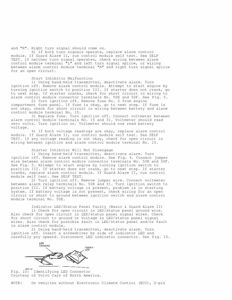
Indicator LED/Status Panel Faulty (Basic & Guard Alarm II) 1) Check for open circuit in LED/status panel ground wire.Also check for open circuit in LED/status panel signal wires. Checkfor short circuit to ground or voltage in LED/status panel signalwires. Also check for possible fault in LED/status panel and/or faultin alarm control module. 2) Using hand-held transmitter, deactivate alarm. Turnignition off. Insert a screwdriver by side of indicator LED andcarefully pry upward. Disconnect LED indicator connector. See Fig. 10.
Fig. 10: Identifying LED ConnectorCourtesy of Volvo Cars of North America.
NOTE: On vehicles without Electronic Climate Control (ECC), 2-pin
connector is used. On vehicles with ECC, 5-pin connector is used, as A/C sun sensor is integrated in indicator LED.
3) Connect ohmmeter between ground and LED connector terminalNo. 2 (without Electronic Climate Control - ECC) or No. 5 (with ECC).If ohmmeter reads zero ohms, go to next step. If ohmmeter does notread zero ohms, check LED ground wire for an open circuit. 4) Turn ignition off. Connect an ohmmeter between LEDconnector terminals No. 1 and 2 (without ECC) or between terminals No.1 and 5 (with ECC). If ohmmeter reads high resistance, go to nextstep. If ohmmeter does not read high resistance, check LED signal wirefor a short circuit to ground. 5) Turn ignition on, then off. Connect voltmeter between LEDconnector terminals No. 1 and 2 (without ECC) or between terminals No.1 and 5 (with ECC). If voltmeter reads zero volts, go to next step. Ifvoltmeter does not read zero volts, check LED signal wire for a shortcircuit to voltage. 6) Turn ignition off. To check system with LED indicatormounted on speaker grille, go to next step. To check system with LEDindicator mounted on instrument panel, remove alarm control module.See Fig. 4. Connect jumper wire between alarm control module connectorterminals DI and No. 31. See Fig. 5. Connect an ohmmeter between LEDindicator connector terminals No. 1 and 2 (without ECC) or betweenterminals No. 1 and 5 (with ECC). Ohmmeter should read about zeroohms. Go to next step. 7) Turn ignition off. Disconnect alarm control moduleconnector. See Fig. 4. Connect ohmmeter between 2-pin connectorterminal No. 1 (Blue/White or Red wire) and 5-pin connector terminalNo. 1 (Black wire). If ohmmeter reads zero ohms, go to next step. Ifohmmeter does not read zero ohms, check LED signal lead for an opencircuit. 8) Turn ignition off. Remove jumper wire from alarm controlmodule connector terminals DI and No. 31. See Fig. 5. Reinstall alarmcontrol module. Activate alarm using hand-held transmitter. Wait 10seconds. Trigger alarm by opening hood. Deactivate alarm using hand-held transmitter. 9) On vehicles without ECC, connect voltmeter between LEDconnector terminals No. 1 and 2. On vehicles with ECC, connectvoltmeter between LED connector terminals No. 1 and 5. If voltmeterreads at least 4 volts, install new LED. If voltmeter does not read atleast 4 volts, replace alarm control module. If Guard Alarm II, runcontrol module self test. See SELF TEST.
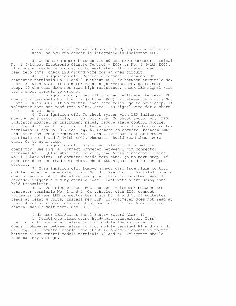
Indicator LED/Status Panel Faulty (Guard Alarm I) 1) Deactivate alarm using hand-held transmitter. Turnignition off. Disconnect alarm control module 10-pin connector.Connect ohmmeter between alarm control module terminal K1 and ground.See Fig. 11. Ohmmeter should read about zero ohms. Connect voltmeterbetween alarm control module terminals K1 and K4. Voltmeter shouldread battery voltage.
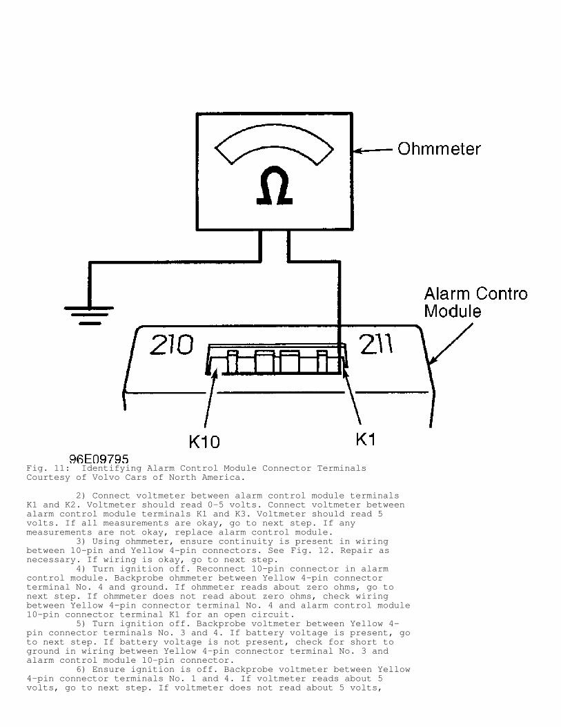
Fig. 11: Identifying Alarm Control Module Connector TerminalsCourtesy of Volvo Cars of North America.
2) Connect voltmeter between alarm control module terminalsK1 and K2. Voltmeter should read 0-5 volts. Connect voltmeter betweenalarm control module terminals K1 and K3. Voltmeter should read 5volts. If all measurements are okay, go to next step. If anymeasurements are not okay, replace alarm control module. 3) Using ohmmeter, ensure continuity is present in wiringbetween 10-pin and Yellow 4-pin connectors. See Fig. 12. Repair asnecessary. If wiring is okay, go to next step. 4) Turn ignition off. Reconnect 10-pin connector in alarmcontrol module. Backprobe ohmmeter between Yellow 4-pin connectorterminal No. 4 and ground. If ohmmeter reads about zero ohms, go tonext step. If ohmmeter does not read about zero ohms, check wiringbetween Yellow 4-pin connector terminal No. 4 and alarm control module10-pin connector terminal K1 for an open circuit. 5) Turn ignition off. Backprobe voltmeter between Yellow 4-pin connector terminals No. 3 and 4. If battery voltage is present, goto next step. If battery voltage is not present, check for short toground in wiring between Yellow 4-pin connector terminal No. 3 andalarm control module 10-pin connector. 6) Ensure ignition is off. Backprobe voltmeter between Yellow4-pin connector terminals No. 1 and 4. If voltmeter reads about 5volts, go to next step. If voltmeter does not read about 5 volts,
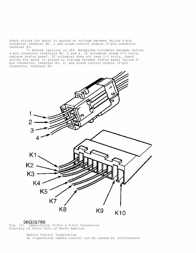
check wiring for short to ground or voltage between Yellow 4-pinconnector terminal No. 1 and alarm control module 10-pin connectorterminal K3. 7) Ensure ignition is off. Backprobe voltmeter between Yellow4-pin connector terminals No. 2 and 4. If voltmeter reads 0-5 volts,replace status panel. If voltmeter does not read 0-5 volts, checkwiring for short to ground or voltage between status panel Yellow 4-pin connector, terminal No. 2, and alarm control module 10-pinconnector, terminal K2.
Fig. 12: Identifying 10-Pin & 4-Pin ConnectorsCourtesy of Volvo Cars of North America.
Remote Control Inoperative An inoperative remote control can be caused by interference
from surroundings (buildings, vehicles, etc.), defective batteries,incorrectly programmed remote, or defective remote control unit.
Alarm Cannot Be Activated Or Deactivated 1) Check for open or short circuit in ground wire to alarmrelay connector. Check for open or short circuit in voltage supplywire to alarm relay connector. 2) Check for open or short circuit in ignition supply wire toalarm control module connector. Check if remote control is programmedincorrectly. Check for faulty fuse No. 2 or 6. Check for defectiveremote control, central locking relay, relief relay, or alarm controlmodule. 3) On basic alarm system, check for defective ignitionswitch, open or short circuit in signal wire between central lockingrelay and alarm control module, or short circuit to voltage in signalwire between central locking relay and alarm control module. 4) On Guard Alarm I system, check for open circuit inaccessory cable ground wire. Check for short circuit to ground inaccessory cable supply. Check for open circuit in accessory cablesupply.
Central Locking System Does Not Lock Or Open When Activated Or Deactivated (Guard Alarm I & II) Check for open or short circuit in signal wire betweencentral locking relay and alarm control module. Check for shortcircuit to voltage in signal wire between central locking relay andalarm control module. Check for defective central locking relay oralarm control module.
Panic Function Does Not Work (Guard Alarm I & II) Check for failing remote control range. Check for defectiveremote control. Check batteries. Check for defective remote controlmodule.
Alarm Will Not Reactivate (Guard Alarm I & II) Check for defective alarm control module.
REMOVAL & INSTALLATION
WARNING: Deactivate air bag system before performing any service operation. For 1995 850, see AIR BAG RESTRAINT SYSTEM, for 1996 850, see AIR BAG RESTRAINT SYSTEM article. Do not apply electrical power to any component on steering column without first deactivating air bag system. Air bag may deploy.
ALARM CONTROL MODULE
Removal & Installation Alarm control module is located under left side of instrumentpanel. See Fig. 4.
WIRING DIAGRAMS
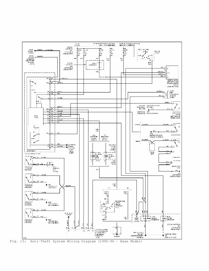
Fig. 13: Anti-Theft System Wiring Diagram (1995-96 - Base Model)
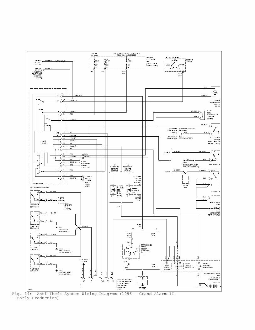
Fig. 14: Anti-Theft System Wiring Diagram (1996 - Grand Alarm II- Early Production)
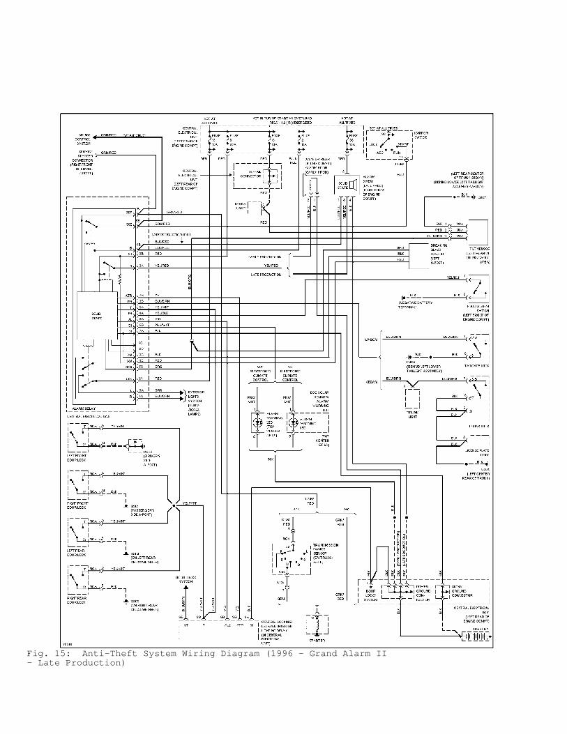
Fig. 15: Anti-Theft System Wiring Diagram (1996 - Grand Alarm II- Late Production)