Embed Size (px)
Citation preview

1/13
Classification: Reference: Date:
RA19-002 NTB19-082 October 24, 2019
VOLUNTARY SERVICE CAMPAIGN 2013 ALTIMA SEDAN; REAR LOWER LINK
CAMPAIGN ID #: P9324 APPLIED VEHICLE: 2013 Altima Sedan (L33)
Check Service COMM or Dealer Business Systems (DBS) National Service History to confirm campaign eligibility.
INTRODUCTION
Nissan is conducting this voluntary service campaign on certain specific model year 2013 Altima Sedan vehicles. Both rear lower links, located at the rear suspension, will be replaced. This service will be performed at no charge to the customer for parts or labor. IDENTIFICATION NUMBER
Nissan has assigned identification number P9324 to this campaign. This number must appear on all communication and documentation of any nature dealing with this campaign. DEALER RESPONSIBILITY
Dealers are to repair vehicles falling within range of this campaign that enter the service department. This includes vehicles purchased from private parties, vehicles presented by transient (tourists) owners, and vehicles in a dealer’s inventory. Nissan Bulletins are intended for use by qualified technicians, not 'do-it-yourselfers'. Qualified technicians are properly trained individuals who have the equipment, tools, safety instruction, and know-how to do a job properly and safely. NOTE: If you believe that a described condition may apply to a particular vehicle, DO NOT assume that it does. See your Nissan dealer to determine if this applies to your vehicle.

2/13 NTB19-082
REQUIRED SPECIAL TOOL
Coil Spring Compressor J-52929
Figure 1
Additional tools are available from Tech•Mate: 1-800-662-2001 or nissantechmate.com
When using the spring compressor, wear proper eye protection. Dirt or debris may enter the eye, causing injury.
Inspect the condition of the spring compressor before each use. Do not use the
spring compressor if it is not in serviceable condition. Injury may occur when parts are bent, cracked, etc.
Do not drop the spring compressor when it is holding a compressed spring. If
dropped, the spring may separate from the spring compressor and launch toward your body, causing injury.
Upper ball
# 37731
Support plates
Lower ball# 311835 Threaded rod
# 49169
Thrust washer
# 211206
Barrel nut # 37666
Support plates# 42913-BK2
Pin # 204444

3/13 NTB19-082
SERVICE PROCEDURE
HINT: Most of the SERVICE PROCEDURE will show a repair performed on the left rear side. The same repair will repeated on the right rear side. 1. Set and raise the vehicle on a lift. 2. Remove both rear tire and wheel assemblies. 3. Mark the suspension alignment washer to the frame on all four (4) rear lower link
alignment bolts (see Figure 2).
Figure 2

4/13 NTB19-082
4. Install the upper ball in the cavity of one of the support plates of tool J-52929, upper ball facing upward, and then place the support plate midway inside the coil spring.
HINT: The upper ball can be identified by its cross drilled pin hole.
Figure 3
5. Install the other small support plate, with the ball cavity facing down, as low as possible inside the coil spring.
Figure 4
Support plate
Upper ball
Support plate – cavity facing down

5/13 NTB19-082
6. Assemble the following pieces of tool J-52929 as shown in Figure 5: The threaded rod, lower ball, thrust bearing, and barrel nut.
To keep the pieces together, thread the barrel nut onto the threaded rod.
Figure 5
7. Install the assembled pieces, pin hole end first, from the bottom of the coil spring through both support plates and the upper ball.
Figure 6
Pin hole
Rod
Barrel nut

6/13 NTB19-082
8. Install the pin of tool J-52929 through the upper ball and threaded rod up to its O-ring stopper.
Figure 7
9. Align the upper ball into the upper support plate cavity so that the pin rests in the slots.
Figure 8
Upper ball
Pin
Pin
Slot
Cavity
O-ring stopper

7/13 NTB19-082
10. Rotate the threaded rod and upper support plate together as an assembly counterclockwise until the upper support plate contacts the upper rubber seat.
Figure 9
11. Slide the lower ball up the rod and into the lower support plate cavity while aligning the lower ball’s notch into one of the lower support plate’s slots.
Make sure the lower plate stays as low on the coil spring as possible.
12. Thread the barrel nut up the threaded rod until the thrust washer makes contact with the lower ball (see Figure 10).
Figure 10
Turn plate until it contacts rubber seatRotate plate until it
contacts rubber seat
Lower ball
Thrust washer (barrel nut not shown)
Lower plate

8/13 NTB19-082
13. Compress the coil spring until the lower ball bottoms out on the threaded rod.
To compress the coil spring, use a wrench, deep socket, or other suitable tool to turn the barrel nut clockwise.
Figure 11
14. Remove the two (2) knuckle bolt nuts and two (2) alignment bolt nuts but do NOT remove the related bolts at this time.
HINT: These nuts will not be reused and will be replaced with new ones (see PARTS INFORMATION on the last page of this bulletin).
Figure 12
9/13 NTB19-082
15. Remove the nut holding the rear stabilizer connecting rod to the rear lower link.
Figure 13
16. Remove the coil spring and tool J-52929 as an assembly:
a. Remove both inside rear lower link (alignment) bolts. HINT: Due to being marked earlier, these bolts need to go back to their original
locations during reassembly. b. Swing the rear lower link downward. c. Remove the connecting rod assembly from the rear lower link. d. Remove the coil spring and tool J-52929 as an assembly.
Figure 14
Where one of two alignment bolts removed
Connecting rod assembly not
shown
10/13 NTB19-082
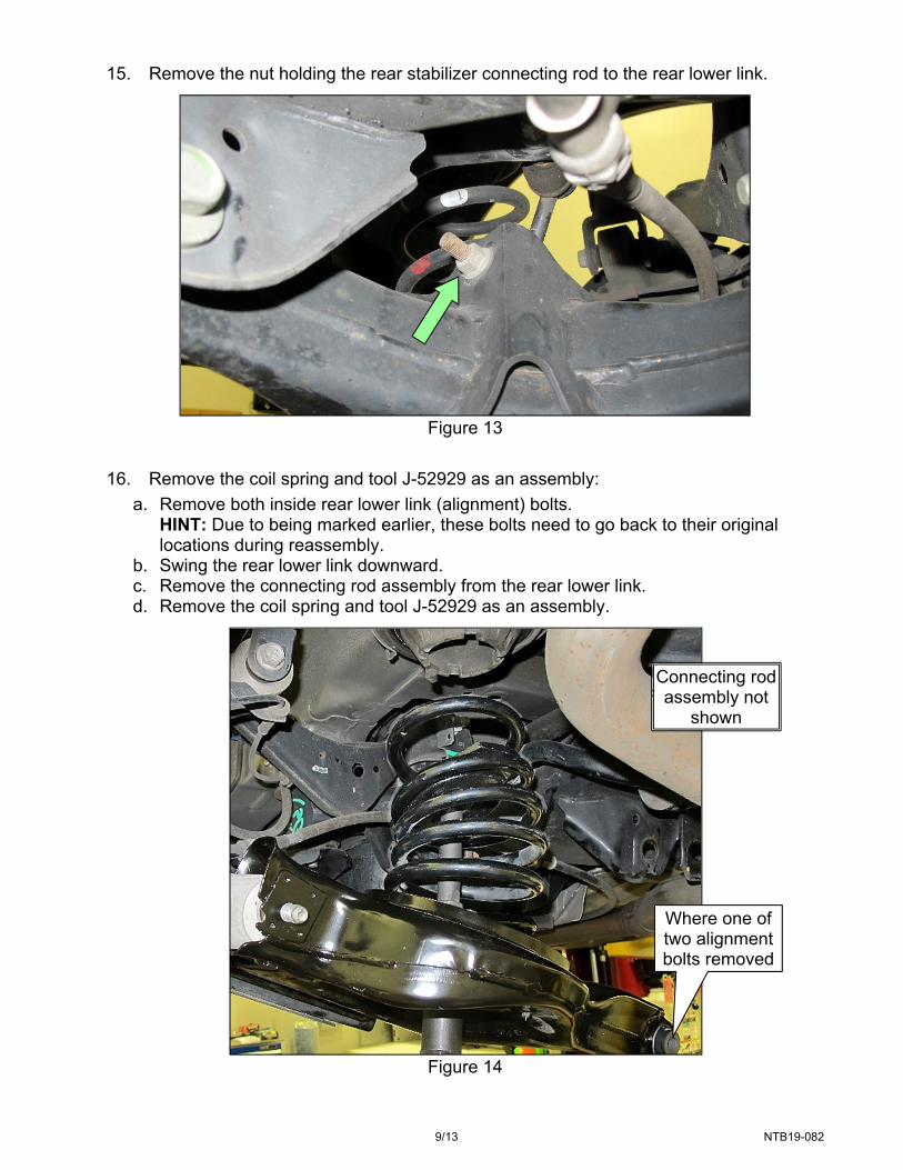
17. Remove the two (2) remaining (knuckle) bolts, and then remove the rear lower link from the vehicle.
Figure 15
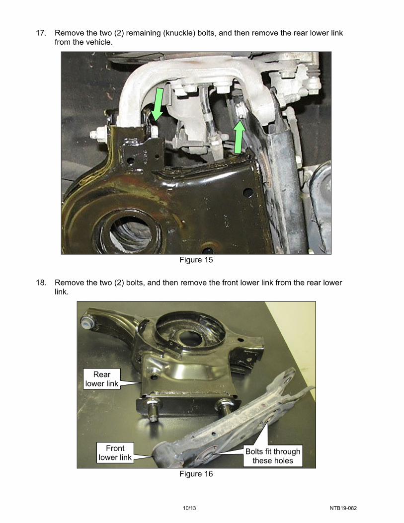
18. Remove the two (2) bolts, and then remove the front lower link from the rear lower link.
Figure 16
Bolts fit through these holes
Bolts fit through these holes
Front lower link
Rear lower link

11/13 NTB19-082
19. Install a new rear lower link (see PARTS INFORMATION on the last page of this bulletin) in reverse order of disassembly.
Transfer the lower rubber seat from the old rear lower link to the new rear lower link.
HINT: To make reassembly easier: When assembling the front and rear lower links, hand tighten the bolts, and then back off by two (2) turns. This allows for extra movement of these parts.
HINT: Torque all fasteners from step 19 through step 20 with the vehicle unladed and the weight of the vehicle on the ground. A drive-on lift will make fastener torquing easier.
Front lower link-to-rear lower link bolts torque: 111 N•m (11 kg-m, 82 ft-lbs)
When installing the coil spring (still compressed):
a. Make sure the orientation of the coil spring is as shown in Figure 17: A single painted mark is above the two painted marks.
Figure 17
b. Make sure the upper rubber seat is secured to the bracket, which is secured to
the vehicle.
Make sure the protrusion is aligned, facing into the vehicle.
Figure 18
Protrusion
Bracket
1 of 3 tabs
Upper rubber
seat
1 of 3 tabs
Upper rubber seat opening
Top end of coil spring One painted mark
Two painted marks

12/13 NTB19-082
c. Align the coil spring by placing its lower end as shown in Figure 19.
Figure 19
Rear stabilizer connecting rod nut torque: 44 N•m (4.5 kg-m, 32 ft-lbs) Nuts-to-alignment bolts torque: 146 N•m (15 kg-m, 108 ft-lb)
HINT: Place the alignment bolts in their original locations, and then line up the marks when torquing.
Nuts-to-knuckle bolts torque: 118 N•m (12 kg-m, 87 ft-lbs)
20. Perform steps 4-19 on the other rear lower link. 21. Reinstall both rear tire & wheel assemblies.
Wheel lug nuts torque: 113 N•m (12 kg-m, 83 ft-lbs)
22. Perform a 4-wheel alignment. 23. Reset the steering angle sensor (neutral position adjustment) with C-III plus.
Maximum gap: 5 mm (0.2. inches)
Lower end of coil spring
Coil spring seat

13/13 NTB19-082
PARTS INFORMATION
DESCRIPTION PART NUMBER QUANTITY
LINK COMPLETE, REAR SUSPENSION (RH rear lower link)
551B0-3TA0D 1
LINK COMPLETE, REAR SUSPENSION (LH rear lower link)
551B1-3TA0D 1
NUT (for alignment bolts) (1) 54588-JA060 4
NUT (for knuckle bolts) (1) 40262-JA000 4
(1) One-time use part. CLAIMS INFORMATION
Submit a “CM” line claim using the following claims coding:
CAMPAIGN (“CM”) ID DESCRIPTION OP CODE FRT
P9324 Remove and Install Rear Lower Link Assemblies (Left And Right)
P93240 2.7 hrs
AMENDMENT HISTORY
PUBLISHED DATE REFERENCE DESCRIPTION
October 24, 2019 NTB19-082 Original bulletin published