Embed Size (px)
Citation preview
Instructions-Parts
Volumetric Fluid Flow Meter 308778M
ENG
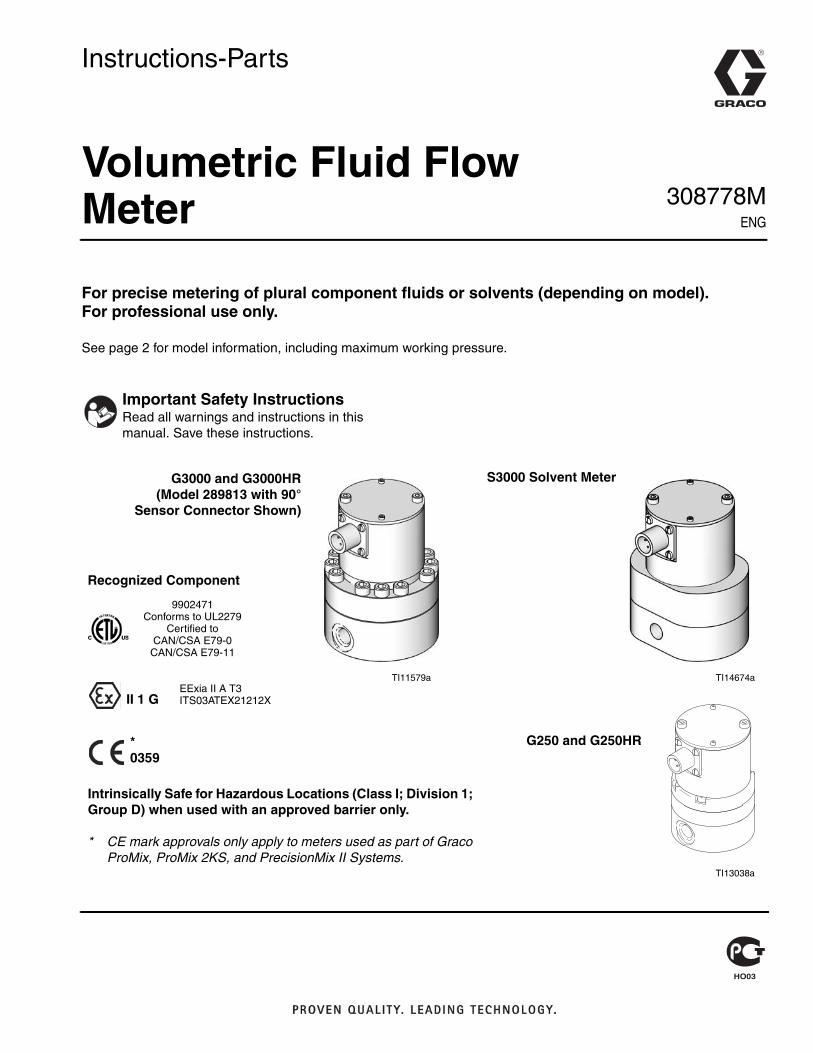
For precise metering of plural component fluids or solvents (depending on model). For professional use only.
See page 2 for model information, including maximum working pressure.
Important Safety InstructionsRead all warnings and instructions in this manual. Save these instructions.
TI11579a
Intrinsically Safe for Hazardous Locations (Class I; Division 1; Group D) when used with an approved barrier only.
* CE mark approvals only apply to meters used as part of Graco ProMix, ProMix 2KS, and PrecisionMix II Systems.
*0359
Recognized Component
9902471Conforms to UL2279
Certified toCAN/CSA E79-0
CAN/CSA E79-11
EExia II A T3ITS03ATEX21212XII 1 G
G3000 and G3000HR(Model 289813 with 90°
Sensor Connector Shown)
G250 and G250HR
TI13038a
TI14674a
S3000 Solvent Meter
Models
2 308778M
ContentsModels . . . . . . . . . . . . . . . . . . . . . . . . . . . . . . . . . . . 2
Low Pressure Fluid Meters . . . . . . . . . . . . . . . . . 2High Pressure Fluid Meters . . . . . . . . . . . . . . . . 2High Pressure Solvent Meters . . . . . . . . . . . . . . 2
Warnings . . . . . . . . . . . . . . . . . . . . . . . . . . . . . . . . . 3Installation . . . . . . . . . . . . . . . . . . . . . . . . . . . . . . . . 5
Dust and Foreign Matter . . . . . . . . . . . . . . . . . . . 5Installing the Flow Meter . . . . . . . . . . . . . . . . . . . 5Grounding . . . . . . . . . . . . . . . . . . . . . . . . . . . . . . 6
Operation . . . . . . . . . . . . . . . . . . . . . . . . . . . . . . . . . 7Pressure Relief Procedure . . . . . . . . . . . . . . . . . 7Flow Meter Function . . . . . . . . . . . . . . . . . . . . . . 7Recommended Usage . . . . . . . . . . . . . . . . . . . . 7Flow Volume Range . . . . . . . . . . . . . . . . . . . . . . 7Checking the Meter Accuracy . . . . . . . . . . . . . . . 7
Troubleshooting . . . . . . . . . . . . . . . . . . . . . . . . . . . . 8Maintenance . . . . . . . . . . . . . . . . . . . . . . . . . . . . . . . 9
Residue Build-up on the Meter Gears . . . . . . . . . 9Flushing . . . . . . . . . . . . . . . . . . . . . . . . . . . . . . . . 9Cleaning or Servicing the Meter Chamber . . . . 10
Parts . . . . . . . . . . . . . . . . . . . . . . . . . . . . . . . . . . . . 11Flow Meter Kits, for ProMix 2KS Wall Fluid Panel 11Bare Meter Assemblies . . . . . . . . . . . . . . . . . . . 12Solvent Meter Assembly . . . . . . . . . . . . . . . . . . 13
Dimensions . . . . . . . . . . . . . . . . . . . . . . . . . . . . . . . 16Technical Data . . . . . . . . . . . . . . . . . . . . . . . . . . . . 18Pressure Drop Curve . . . . . . . . . . . . . . . . . . . . . . . 19Graco Standard Warranty . . . . . . . . . . . . . . . . . . . 20Graco Information . . . . . . . . . . . . . . . . . . . . . . . . . 20
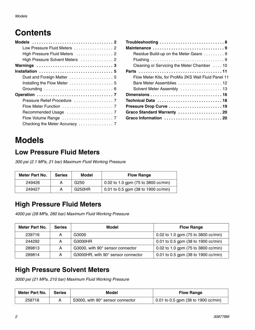
ModelsLow Pressure Fluid Meters300 psi (2.1 MPa, 21 bar) Maximum Fluid Working Pressure
High Pressure Fluid Meters4000 psi (28 MPa, 280 bar) Maximum Fluid Working Pressure
High Pressure Solvent Meters3000 psi (21 MPa, 210 bar) Maximum Fluid Working Pressure
Meter Part No. Series Model Flow Range
249426 A G250 0.02 to 1.0 gpm (75 to 3800 cc/min)
249427 A G250HR 0.01 to 0.5 gpm (38 to 1900 cc/min)
Meter Part No. Series Model Flow Range
239716 A G3000 0.02 to 1.0 gpm (75 to 3800 cc/min)
244292 A G3000HR 0.01 to 0.5 gpm (38 to 1900 cc/min)
289813 A G3000, with 90° sensor connector 0.02 to 1.0 gpm (75 to 3800 cc/min)
289814 A G3000HR, with 90° sensor connector 0.01 to 0.5 gpm (38 to 1900 cc/min)
Meter Part No. Series Model Flow Range
258718 A S3000, with 90° sensor connector 0.01 to 0.5 gpm (38 to 1900 cc/min)
Warnings
308778M 3
WarningsThe following warnings are for the setup, use, grounding, maintenance, and repair of this equipment. The exclama-tion point symbol alerts you to a general warning and the hazard symbol refers to procedure-specific risk. Refer back to these warnings. Additional, product-specific warnings may be found throughout the body of this manual where applicable.
WARNINGSKIN INJECTION HAZARD High-pressure fluid from gun, hose leaks, or ruptured components will pierce skin. This may look like just a cut, but it is a serious injury that can result in amputation. Get immediate surgical treatment.• Do not point gun at anyone or at any part of the body.• Do not put your hand over the spray tip.• Do not stop or deflect leaks with your hand, body, glove, or rag.• Do not spray without tip guard and trigger guard installed.• Engage trigger lock when not spraying.• Follow Pressure Relief Procedure in this manual, when you stop spraying and before cleaning,
checking, or servicing equipment.
FIRE AND EXPLOSION HAZARD Flammable fumes, such as solvent and paint fumes, in work area can ignite or explode. To help prevent fire and explosion:• Use equipment only in well ventilated area.• Eliminate all ignition sources; such as pilot lights, cigarettes, portable electric lamps, and plastic drop
cloths (potential static arc). • Keep work area free of debris, including solvent, rags and gasoline.• Do not plug or unplug power cords, or turn power or light switches on or off when flammable fumes
are present.• Ground all equipment in the work area. See Grounding instructions.• Use only grounded hoses.• Hold gun firmly to side of grounded pail when triggering into pail.• If there is static sparking or you feel a shock, stop operation immediately. Do not use equipment
until you identify and correct the problem.• Keep a working fire extinguisher in the work area.
SPECIAL CONDITIONSEquipment must comply with the following conditions to avoid a hazardous condition which can cause fire, explosion, or electric shock:• Never use the flow meter with an electrostatic gun isolation stand.• Keep liquids away from the electronic sensor device.• Do not service the electronic sensor. Return it to your Graco distributor for service.• Sensor housing is of aluminum construction. Precautions must be taken to avoid impacts or contact
with moving parts.
PRESSURIZED EQUIPMENT HAZARD Fluid from the gun/dispense valve, leaks, or ruptured components can splash in the eyes or on skin and cause serious injury.• Follow Pressure Relief Procedure in this manual, when you stop spraying and before cleaning,
checking, or servicing equipment. • Tighten all fluid connections before operating the equipment.• Check hoses, tubes, and couplings daily. Replace worn or damaged parts immediately.
Warnings
4 308778M
EQUIPMENT MISUSE HAZARD Misuse can cause death or serious injury.• Do not operate the unit when fatigued or under the influence of drugs or alcohol.• Do not exceed the maximum working pressure or temperature rating of the lowest rated system
component. See Technical Data in all equipment manuals.• Use fluids and solvents that are compatible with equipment wetted parts. See Technical Data in all
equipment manuals. Read fluid and solvent manufacturer’s warnings. For complete information about your material, request MSDS forms from distributor or retailer.
• Check equipment daily. Repair or replace worn or damaged parts immediately with genuine manu-facturer’s replacement parts only.
• Do not alter or modify equipment.• Use equipment only for its intended purpose. Call your distributor for information.• Route hoses and cables away from traffic areas, sharp edges, moving parts, and hot surfaces.• Do not kink or over bend hoses or use hoses to pull equipment.• Keep children and animals away from work area.• Comply with all applicable safety regulations.
TOXIC FLUID OR FUMES HAZARD Toxic fluids or fumes can cause serious injury or death if splashed in the eyes or on skin, inhaled, or swallowed.• Read MSDS’s to know the specific hazards of the fluids you are using.• Store hazardous fluid in approved containers, and dispose of it according to applicable guidelines.• Always wear impervious gloves when spraying or cleaning equipment.
PERSONAL PROTECTIVE EQUIPMENT You must wear appropriate protective equipment when operating, servicing, or when in the operating area of the equipment to help protect you from serious injury, including eye injury, inhalation of toxic fumes, burns, and hearing loss. This equipment includes but is not limited to:• Protective eyewear • Clothing and respirator as recommended by the fluid and solvent manufacturer• Gloves• Hearing protection
WARNING
Installation
308778M 5
Installation
Dust and Foreign MatterAvoid having dust or foreign matter enter the flow meter by taking the following precautions:
• Thoroughly flush the fluid supply lines before install-ing the flow meter.
• When installing fittings, make sure that no sealing tape overlaps into the inside of the pipe.
• Install a 100 mesh fluid filter upstream of the flow meter.
Installing the Flow Meter• Flow volume can only be measured at the location
where the flow meter is installed.
• The Fluid Flow Meters are intrinsically safe for Class I; Division 1; Group D hazardous indoor (NEMA 1) locations when installed with an intrinsically safe power device and wiring.
Refer to ANSI standards ISA-RP12.6, NEC Article 504 and the Canadian Electrical Code Appendix F.
• Do not use more than 200 ft. (61 m) of cable.
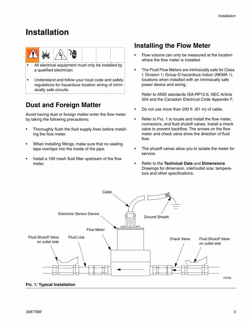
• Refer to FIG. 1 to locate and install the flow meter, connectors, and fluid shutoff valves. Install a check valve to prevent backflow. The arrows on the flow meter and check valve show the direction of fluid flow.
• The shutoff valves allow you to isolate the meter for service.
• Refer to the Technical Data and Dimensions Drawings for dimension, inlet/outlet size, tempera-ture and other specifications.
• All electrical equipment must only be installed by a qualified electrician.
• Understand and follow your local code and safety regulations for hazardous location wiring of intrin-sically safe circuits.
FIG. 1: Typical Installation
7379A
Cable
Electronic Sensor Device
Flow Meter
Fluid LineFluid Shutoff Valveon outlet side
Ground Sheath
Check Valve Fluid Shutoff Valveon outlet side
Installation
6 308778M
Grounding
1. Ground the flow meter by connecting a grounded cable to the sensor.
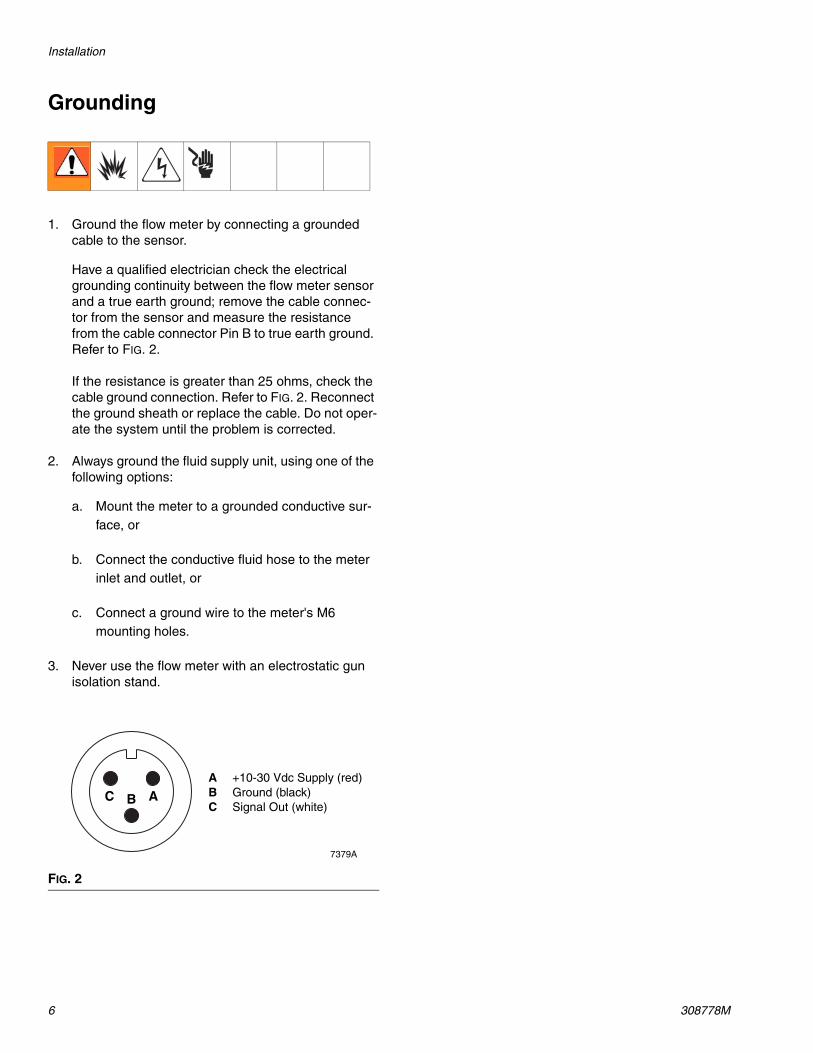
Have a qualified electrician check the electrical grounding continuity between the flow meter sensor and a true earth ground; remove the cable connec-tor from the sensor and measure the resistance from the cable connector Pin B to true earth ground. Refer to FIG. 2.
If the resistance is greater than 25 ohms, check the cable ground connection. Refer to FIG. 2. Reconnect the ground sheath or replace the cable. Do not oper-ate the system until the problem is corrected.
2. Always ground the fluid supply unit, using one of the following options:
a. Mount the meter to a grounded conductive sur-face, or
b. Connect the conductive fluid hose to the meter inlet and outlet, or
c. Connect a ground wire to the meter's M6 mounting holes.
3. Never use the flow meter with an electrostatic gun isolation stand.
FIG. 2
7379A
ABCA +10-30 Vdc Supply (red)B Ground (black)C Signal Out (white)
Operation
308778M 7
Operation
Pressure Relief Procedure
1. Shut off the fluid supply to the meter.
2. Shut off all electrical power to the fluid system.
3. Follow the Pressure Relief Procedure for your fluid system dispensing device.
Flow Meter FunctionThis is a positive displacement, gear flow meter. The gear flow meter is highly accurate, even with low flow rates. The fluid flowing through the meter rotates the gears. The gear tooth is picked up by a sensor device, which produces an impulse for every gear tooth passing by.
Recommended Usage
• See the Technical Data for fluid and ambient tem-perature limits.
• Only use the flow meter with fluids that are compati-ble with the “Wetted Parts” listed in the Technical Data.
Flow Volume RangeThe G3000 and G250 meters flow volume range is 0.02-1.0 gal./min. (75-3800 cc/min.).
The G3000HR and G250HR meters flow volume range is 0.01-0.5 gal./min. (38-1900 cc/min.).
The S3000 solvent meter flow volume range is 0.01-0.5 gpm (38-1900 cc/min).
Checking the Meter Accuracy1. To check the accuracy of the meter, turn your gun
fan and atomizing air off, then trigger the fluid into a graduated cylinder; dispense at least 500 cc of fluid.
2. Measure the volume of fluid in the beaker in cubic-centimeters (cc) and read the volume on the flow meter monitor.
G3000 and G250: If the flow meter scale factor is not between 0.112-0.140 cc/pulse, follow the clean-ing procedure on page 10, then recalibrate the flow meter.
G3000HR and G250HR: If the flow meter scale fac-tor is not between 0.05-0.07 cc/pulse, follow the cleaning procedure on page 10, then recalibrate the flow meter.
S3000: If the solvent meter scale factor is not between 0.019-0.022 cc/pulse, follow the cleaning procedure on page 10, then recalibrate the flow meter.
Do not exceed the maximum working pressure of your meter or any component or accessory in your system.
NOTICEThe flow meter gears and bearings can be damaged if they rotate at too high a speed. To avoid high speed rotation, open the fluid valve gradually. Do not over-speed the meter with air or solvent. To prolong meter life, do not exceed the meter’s maximum flow rate.
Troubleshooting
8 308778M
TroubleshootingBefore servicing this equipment always make sure to relieve the pressure.
NOTICEThe sensor is not a serviceable part. Replace it if it is malfunctioning.
Problem Cause Solution
No flow volume displayed at monitor-ing unit.
Flow volume is too low to measure. Increase flow volume.
Fluid is not flowing. Repair.
Damaged cable. Replace cable.
Improper input voltage to sensor. Make sure input voltage is 10-30 Vdc.
Damaged sensor. Replace sensor if it is malfunctioning.
Fluid is not flowing. Clogs in fluid line or in meter. Clean fluid line and/or meter; see Maintenance on page 9.
Gears worn or damaged. Repair meter; see Maintenance on page 9.
Maintenance
308778M 9
Maintenance
Residue Build-up on the Meter GearsResidue build-up may cause the meter gears to bind or stop rotating, which decreases the meter accuracy and makes meter recalibration necessary. As more build-up occurs, recalibration is required more often.
The frequency that your meter requires cleaning depends on the type of fluid being used. Excessive resi-due build-up usually means that you are using improper cleaning solvents and/or cleaning sequences or pro-cesses.
• Check the meter routinely to develop the correct cleaning schedule.
• Use the proper cleaning solvent for the fluid being metered.
Flushing
Flush the fluid supply line and meter fluid reservoir daily with a compatible solvent as instructed below.
1. Follow the Pressure Relief Procedure, on page 7.
2. Connect the fluid line to the solvent supply unit.
3. Flush the meter until it is clean.
4. Follow the Pressure Relief Procedure, then dis-connect the fluid line from the solvent supply unit.
5. Reconnect the fluid line to the fluid (paint) supply.
6. Turn on the fluid supply.
7. Operate until the meter and fluid line are free of sol-vent.
If the meter is not installed in an instrinsically safe location, make sure the power is off or the electronic sensor is disconnected before wiping the outside of the meter clean with a cloth dampened in a compati-ble solvent or flushing the meter.
NOTICEDo not immerse the meter in solvent with the elec-tronic sensor installed. Solvent could damage the electrical components.
Air purge is not recommended for any gear-type flow meter. Air purges do not provide the lubrication the meter gears require.
Maintenance
10 308778M
Cleaning or Servicing the Meter Chamber
1. Follow the Pressure Relief Procedure, on page 7. Then close the fluid shut-off valve on each side of the meter.
2. Disconnect the cable from the electronic sensor device.
3. Disconnect both fluid line fittings and remove the meter from the fluid line.
4. Loosen the two screws and remove the electronic sensor device from the flow meter upper housing. See the Parts drawings, pages 12-15.
5. Loosen the screws. Keep a few threads of two opposing bolts engaged to minimize the torque stress on the shafts when you separate the meter housings.
6. Hold onto the upper housing and gently tap the opposing bolts to separate the lower housing.
7. Remove and inspect the gears and shafts. Clean the meter parts with solvent.
8. Reassemble the gears and shafts into the lower housing in the position they were removed from. Check the gears for free and easy rotation.
9. Make sure the two locating pins are in place.
10. Assemble the two meter housings, making sure to keep them parallel to each other.
11. Install the screws. Tighten them oppositely and evenly, to 12 ft-lb (16 N•m). Do not over-tighten.
12. After re-assembling the meter, test the gear rotation by applying a brief air blast to the meter inlet. You should clearly hear the gears spin.
13. Set the electronic sensor on the upper housing and tighten the two screws hand-tight, about 3.5 ft-lb (4.7 N•m). Do not over-tighten.
NOTICEClean and service the meter at a clean workbench. Use only lint-free cloth on parts.
Installing and servicing this equipment requires access to parts that may cause electric shock or other serious injury if the work is not performed properly. Do not install or service this equipment unless you are trained and qualified.
Use only genuine Graco replacement parts. Substitu-tion of components may impair intrinsic safety. This could result in a failure which causes serious injury and/or substantial property damage.
NOTICETo avoid damaging the shafts, keep the housings par-allel to each other when separating them; do not rock the housings from side to side. Do not use chisels or screwdrivers to split and pry apart the housings.
Parts
308778M 11
Parts
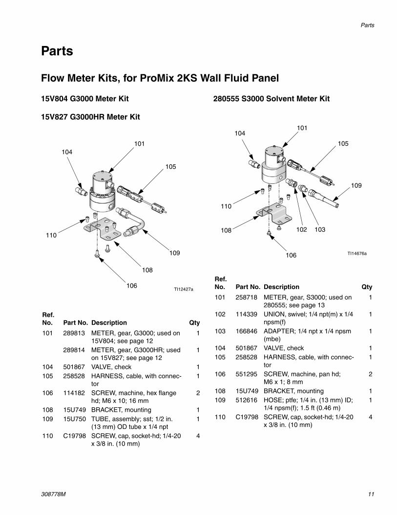
Flow Meter Kits, for ProMix 2KS Wall Fluid Panel
15V804 G3000 Meter Kit
15V827 G3000HR Meter Kit
280555 S3000 Solvent Meter Kit
Ref. No. Part No. Description Qty
101 289813 METER, gear, G3000; used on 15V804; see page 12
1
289814 METER, gear, G3000HR; used on 15V827; see page 12
1
104 501867 VALVE, check 1105 258528 HARNESS, cable, with connec-
tor1
106 114182 SCREW, machine, hex flange hd; M6 x 10; 16 mm
2
108 15U749 BRACKET, mounting 1109 15U750 TUBE, assembly; sst; 1/2 in.
(13 mm) OD tube x 1/4 npt1
110 C19798 SCREW, cap, socket-hd; 1/4-20 x 3/8 in. (10 mm)
4
101104
109
108
105
106
110
TI12427a
Ref. No. Part No. Description Qty
101 258718 METER, gear, S3000; used on 280555; see page 13
1
102 114339 UNION, swivel; 1/4 npt(m) x 1/4 npsm(f)
1
103 166846 ADAPTER; 1/4 npt x 1/4 npsm (mbe)
1
104 501867 VALVE, check 1105 258528 HARNESS, cable, with connec-
tor1
106 551295 SCREW, machine, pan hd; M6 x 1; 8 mm
2
108 15U749 BRACKET, mounting 1109 512616 HOSE; ptfe; 1/4 in. (13 mm) ID;
1/4 npsm(f); 1.5 ft (0.46 m)1
110 C19798 SCREW, cap, socket-hd; 1/4-20 x 3/8 in. (10 mm)
4
101104
109
108
105
106
110
TI14676a
102 103
Parts
12 308778M
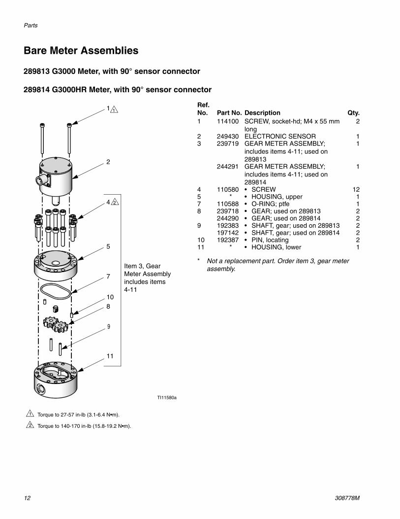
Bare Meter Assemblies
289813 G3000 Meter, with 90° sensor connector
289814 G3000HR Meter, with 90° sensor connector
* Not a replacement part. Order item 3, gear meter assembly.
1
Torque to 27-57 in-lb (3.1-6.4 N•m).
Torque to 140-170 in-lb (15.8-19.2 N•m).
1
2
TI11580a
1
2
4
5
7
8
9
10
11
Item 3, Gear Meter Assemblyincludes items 4-11
2
Ref. No. Part No. Description Qty.1 114100 SCREW, socket-hd; M4 x 55 mm
long2
2 249430 ELECTRONIC SENSOR 13 239719 GEAR METER ASSEMBLY;
includes items 4-11; used on 289813
1
244291 GEAR METER ASSEMBLY;includes items 4-11; used on 289814
1
4 110580 • SCREW 125 * • HOUSING, upper 17 110588 • O-RING; ptfe 18 239718 • GEAR; used on 289813 2
244290 • GEAR; used on 289814 29 192383 • SHAFT, gear; used on 289813 2
197142 • SHAFT, gear; used on 289814 210 192387 • PIN, locating 211 * • HOUSING, lower 1
Parts
308778M 13
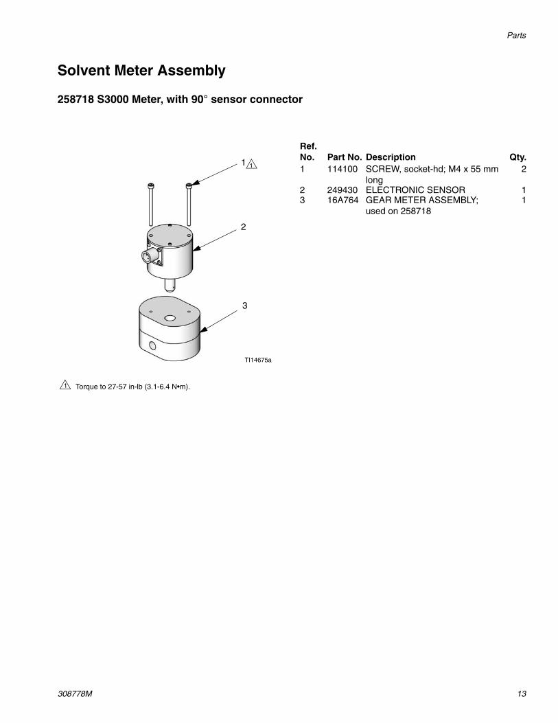
Solvent Meter Assembly
258718 S3000 Meter, with 90° sensor connector
1
Torque to 27-57 in-lb (3.1-6.4 N•m).1
TI14675a
1
2
3
Ref. No. Part No. Description Qty.1 114100 SCREW, socket-hd; M4 x 55 mm
long2
2 249430 ELECTRONIC SENSOR 13 16A764 GEAR METER ASSEMBLY;
used on 2587181
Parts
14 308778M
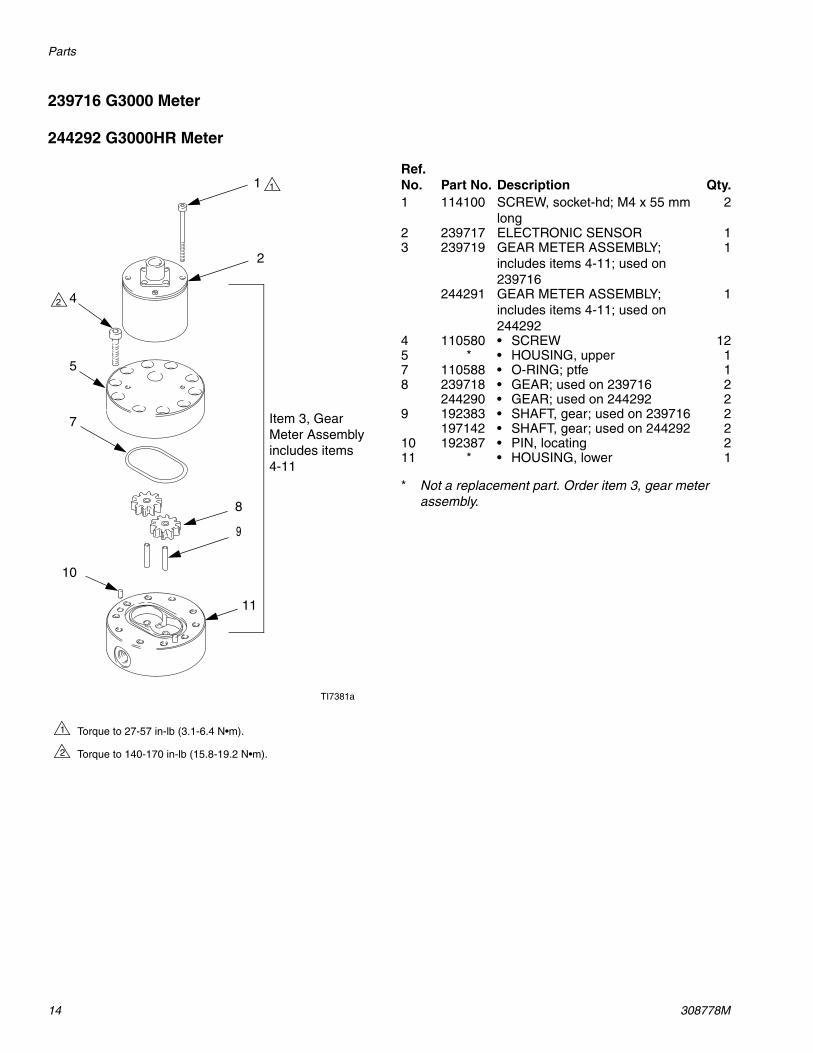
239716 G3000 Meter
244292 G3000HR Meter
* Not a replacement part. Order item 3, gear meter assembly.
Torque to 27-57 in-lb (3.1-6.4 N•m).
Torque to 140-170 in-lb (15.8-19.2 N•m).
1
2
TI7381a
Item 3, Gear Meter Assemblyincludes items 4-11
2
2
4
5
7
8
9
10
11
1 1
Ref. No. Part No. Description Qty.1 114100 SCREW, socket-hd; M4 x 55 mm
long2
2 239717 ELECTRONIC SENSOR 13 239719 GEAR METER ASSEMBLY;
includes items 4-11; used on 239716
1
244291 GEAR METER ASSEMBLY;includes items 4-11; used on 244292
1
4 110580 • SCREW 125 * • HOUSING, upper 17 110588 • O-RING; ptfe 18 239718 • GEAR; used on 239716 2
244290 • GEAR; used on 244292 29 192383 • SHAFT, gear; used on 239716 2
197142 • SHAFT, gear; used on 244292 210 192387 • PIN, locating 211 * • HOUSING, lower 1
Parts
308778M 15
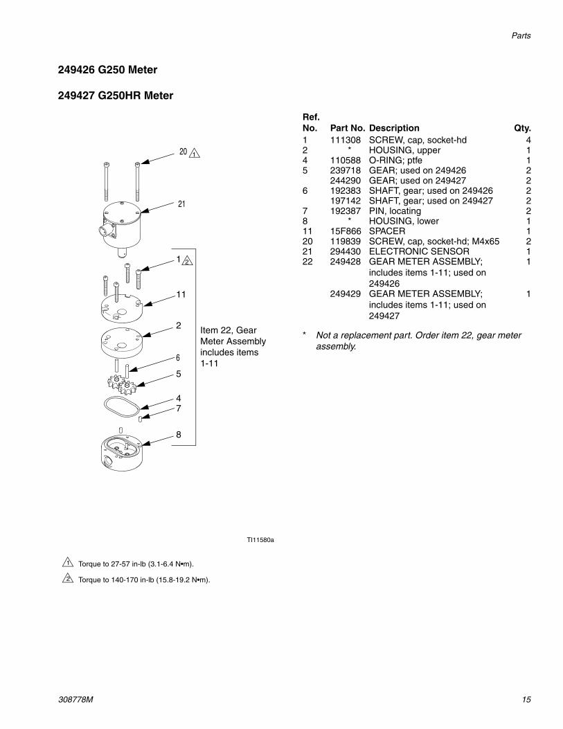
249426 G250 Meter
249427 G250HR Meter
* Not a replacement part. Order item 22, gear meter assembly.
1
Torque to 27-57 in-lb (3.1-6.4 N•m).
Torque to 140-170 in-lb (15.8-19.2 N•m).
1
2
TI11580a
1
2
4
5
7
8
6
11
Item 22, Gear Meter Assemblyincludes items 1-11
2
21
20
Ref. No. Part No. Description Qty.1 111308 SCREW, cap, socket-hd 42 * HOUSING, upper 14 110588 O-RING; ptfe 15 239718 GEAR; used on 249426 2
244290 GEAR; used on 249427 26 192383 SHAFT, gear; used on 249426 2
197142 SHAFT, gear; used on 249427 27 192387 PIN, locating 28 * HOUSING, lower 111 15F866 SPACER 120 119839 SCREW, cap, socket-hd; M4x65 221 294430 ELECTRONIC SENSOR 122 249428 GEAR METER ASSEMBLY;
includes items 1-11; used on 249426
1
249429 GEAR METER ASSEMBLY;includes items 1-11; used on 249427
1
Dimensions
16 308778M
Dimensions
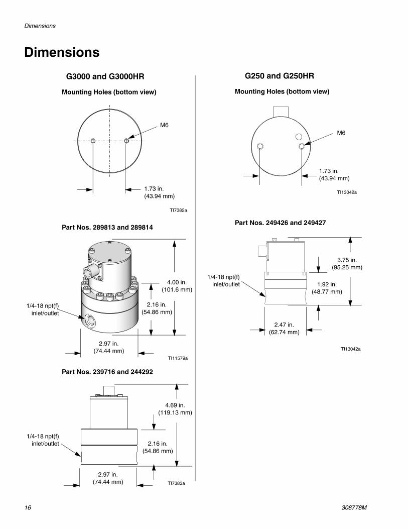
G3000 and G3000HR
Mounting Holes (bottom view)
Part Nos. 289813 and 289814
Part Nos. 239716 and 244292
1.73 in. (43.94 mm)
M6
1/4-18 npt(f)inlet/outlet
1/4-18 npt(f)inlet/outlet
2.97 in. (74.44 mm)
2.16 in. (54.86 mm)
4.69 in. (119.13 mm)
2.97 in. (74.44 mm)
2.16 in. (54.86 mm)
4.00 in. (101.6 mm)
TI11579a
TI7383a
TI7382a
G250 and G250HR
Mounting Holes (bottom view)
Part Nos. 249426 and 249427
M6
1.73 in. (43.94 mm)
1/4-18 npt(f)inlet/outlet
2.47 in. (62.74 mm)
3.75 in. (95.25 mm)
1.92 in. (48.77 mm)
TI13042a
TI13042a
Dimensions
308778M 17
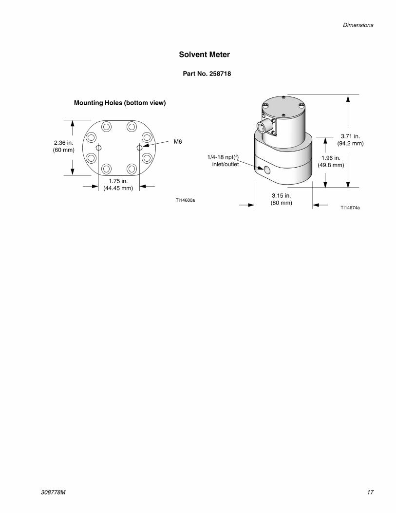
Part No. 258718
1/4-18 npt(f)inlet/outlet
3.15 in. (80 mm)
1.96 in. (49.8 mm)
3.71 in. (94.2 mm)
Solvent Meter
Mounting Holes (bottom view)
1.75 in. (44.45 mm)
M6
TI14674a
2.36 in.(60 mm)
TI14680a
Technical Data
18 308778M
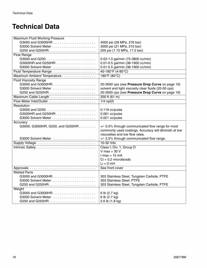
Technical Data
Maximum Fluid Working PressureG3000 and G3000HR. . . . . . . . . . . . . . . . . . . . . . . S3000 Solvent Meter . . . . . . . . . . . . . . . . . . . . . . . G250 and G250HR. . . . . . . . . . . . . . . . . . . . . . . . .
4000 psi (28 MPa, 276 bar)3000 psi (21 MPa, 210 bar)250 psi (1.72 MPa, 17.2 bar)
Flow RangeG3000 and G250 . . . . . . . . . . . . . . . . . . . . . . . . . . G3000HR and G250HR . . . . . . . . . . . . . . . . . . . . . S3000 Solvent Meter . . . . . . . . . . . . . . . . . . . . . . .
0.02-1.0 gal/min (75-3800 cc/min)0.01-0.5 gal/min (38-1900 cc/min)0.01-0.5 gal/min (38-1900 cc/min)
Fluid Temperature Range . . . . . . . . . . . . . . . . . . . . . . . 40-180°F (4-80°C)Maximum Ambient Temperature . . . . . . . . . . . . . . . . . . 180°F (80°C)Fluid Viscosity Range
G3000 and G3000HR. . . . . . . . . . . . . . . . . . . . . . . S3000 Solvent Meter . . . . . . . . . . . . . . . . . . . . . . . G250 and G250HR. . . . . . . . . . . . . . . . . . . . . . . . .
20-3000 cps (see Pressure Drop Curve on page 19)solvent and light viscosity clear fluids (20-50 cps)20-3000 cps (see Pressure Drop Curve on page 19)
Maximum Cable Length . . . . . . . . . . . . . . . . . . . . . . . . 200 ft (61 m)Flow Meter Inlet/Outlet . . . . . . . . . . . . . . . . . . . . . . . . . 1/4 npt(f)Resolution
G3000 and G250 . . . . . . . . . . . . . . . . . . . . . . . . . . G3000HR and G250HR . . . . . . . . . . . . . . . . . . . . . S3000 Solvent Meter . . . . . . . . . . . . . . . . . . . . . . .
0.119 cc/pulse0.061 cc/pulse0.021 cc/pulse
AccuracyG3000, G3000HR, G250, and G250HR . . . . . . . . .
S3000 Solvent Meter . . . . . . . . . . . . . . . . . . . . . . .
+/- 0.5% through communicated flow range for most commonly used coatings. Accuracy will diminish at low viscosities and low flow rates.+/- 2.5% through communicated flow range.
Supply Voltage . . . . . . . . . . . . . . . . . . . . . . . . . . . . . . . 10-30 VdcIntrinsic Safety. . . . . . . . . . . . . . . . . . . . . . . . . . . . . . . . Class I; Div. 1; Group D
V max = 30 VI max = 15 mACi = 0.2 microfaradsLi = 0 mH
Approvals . . . . . . . . . . . . . . . . . . . . . . . . . . . . . . . . . . . See front coverWetted Parts
G3000 and G3000HR. . . . . . . . . . . . . . . . . . . . . . . S3000 Solvent Meter . . . . . . . . . . . . . . . . . . . . . . . G250 and G250HR. . . . . . . . . . . . . . . . . . . . . . . . .
303 Stainless Steel, Tungsten Carbide, PTFE303 Stainless Steel, PTFE303 Stainless Steel, Tungsten Carbide, PTFE
WeightG3000 and G3000HR. . . . . . . . . . . . . . . . . . . . . . . S3000 Solvent Meter . . . . . . . . . . . . . . . . . . . . . . . G250 and G250HR. . . . . . . . . . . . . . . . . . . . . . . . .
6 lb (2.7 kg)6 lb (2.7 kg)2.6 lb (1.8 kg)

Pressure Drop Curve
308778M 19
Pressure Drop Curve
G3000/G250
PSI
140
130
120
110
100
90
80
70
60
50
40
30
20
10
0
0.0 0.1 0.2 0.3 0.4 0.5 0.6 0.7 0.8 0.9 1.0 1.1
G3000HR/G250HR
gal/min
gal/min0.0 0.05 0.10 0.15 0.20 0.25 0.30 0.35 0.40 0.45 0.50 0.55
500 cps
400 cps
300 cps
200 cps
100 cps
50 cps
800
cps
3000
cp
s
2000
cp
s
1500
cp
s
1000
cp
s
S3000 gal/min0.0 0.025 0.05 0.065 0.076 0.083 0.10 0.13 0.16 0.19 0.22 0.25
All written and visual data contained in this document reflects the latest product information available at the time of publication. Graco reserves the right to make changes at any time without notice.
This manual contains English. MM 308778
Graco Headquarters: MinneapolisInternational Offices: Belgium, China, Japan, Korea
GRACO INC. P.O. BOX 1441 MINNEAPOLIS, MN 55440-1441Copyright 1997, Graco Inc. is registered to ISO 9001
www.graco.comRevised 12/2009
Graco Standard WarrantyGraco warrants all equipment referenced in this document which is manufactured by Graco and bearing its name to be free from defects in material and workmanship on the date of sale to the original purchaser for use. With the exception of any special, extended, or limited warranty published by Graco, Graco will, for a period of twelve months from the date of sale, repair or replace any part of the equipment determined by Graco to be defective. This warranty applies only when the equipment is installed, operated and maintained in accordance with Graco’s written recommendations.
This warranty does not cover, and Graco shall not be liable for general wear and tear, or any malfunction, damage or wear caused by faulty installation, misapplication, abrasion, corrosion, inadequate or improper maintenance, negligence, accident, tampering, or substitution of non-Graco component parts. Nor shall Graco be liable for malfunction, damage or wear caused by the incompatibility of Graco equipment with structures, accessories, equipment or materials not supplied by Graco, or the improper design, manufacture, installation, operation or maintenance of structures, accessories, equipment or materials not supplied by Graco.
This warranty is conditioned upon the prepaid return of the equipment claimed to be defective to an authorized Graco distributor for verification of the claimed defect. If the claimed defect is verified, Graco will repair or replace free of charge any defective parts. The equipment will be returned to the original purchaser transportation prepaid. If inspection of the equipment does not disclose any defect in material or workmanship, repairs will be made at a reasonable charge, which charges may include the costs of parts, labor, and transportation.
THIS WARRANTY IS EXCLUSIVE, AND IS IN LIEU OF ANY OTHER WARRANTIES, EXPRESS OR IMPLIED, INCLUDING BUT NOT LIMITED TO WARRANTY OF MERCHANTABILITY OR WARRANTY OF FITNESS FOR A PARTICULAR PURPOSE.
Graco’s sole obligation and buyer’s sole remedy for any breach of warranty shall be as set forth above. The buyer agrees that no other remedy (including, but not limited to, incidental or consequential damages for lost profits, lost sales, injury to person or property, or any other incidental or consequential loss) shall be available. Any action for breach of warranty must be brought within two (2) years of the date of sale.
GRACO MAKES NO WARRANTY, AND DISCLAIMS ALL IMPLIED WARRANTIES OF MERCHANTABILITY AND FITNESS FOR A PARTICULAR PURPOSE, IN CONNECTION WITH ACCESSORIES, EQUIPMENT, MATERIALS OR COMPONENTS SOLD BUT NOT MANUFACTURED BY GRACO. These items sold, but not manufactured by Graco (such as electric motors, switches, hose, etc.), are subject to the warranty, if any, of their manufacturer. Graco will provide purchaser with reasonable assistance in making any claim for breach of these warranties.
In no event will Graco be liable for indirect, incidental, special or consequential damages resulting from Graco supplying equipment hereunder, or the furnishing, performance, or use of any products or other goods sold hereto, whether due to a breach of contract, breach of warranty, the negligence of Graco, or otherwise.
FOR GRACO CANADA CUSTOMERSThe Parties acknowledge that they have required that the present document, as well as all documents, notices and legal proceedings entered into, given or instituted pursuant hereto or relating directly or indirectly hereto, be drawn up in English. Les parties reconnaissent avoir convenu que la rédaction du présente document sera en Anglais, ainsi que tous documents, avis et procédures judiciaires exécutés, donnés ou intentés, à la suite de ou en rapport, directement ou indirectement, avec les procédures concernées.
Graco Information For the latest information about Graco products, visit www.graco.com.
TO PLACE AN ORDER, contact your Graco distributor or call to identify the nearest distributor.Phone: 612-623-6921 or Toll Free: 1-800-328-0211 Fax: 612-378-3505