Embed Size (px)
Citation preview
Volumetric Compensation Systemfor SINUMERIK 840D sl
January 2009
© Siemens AG 2009 - Subject to modificationsIndustry SectorVolumetric Compensation System
2009-01-22 Slide 2/65
Volumetric Compensation System
§ Geometric Errors
© Siemens AG 2009 - Subject to modificationsIndustry SectorVolumetric Compensation System
2009-01-22 Slide 3/65
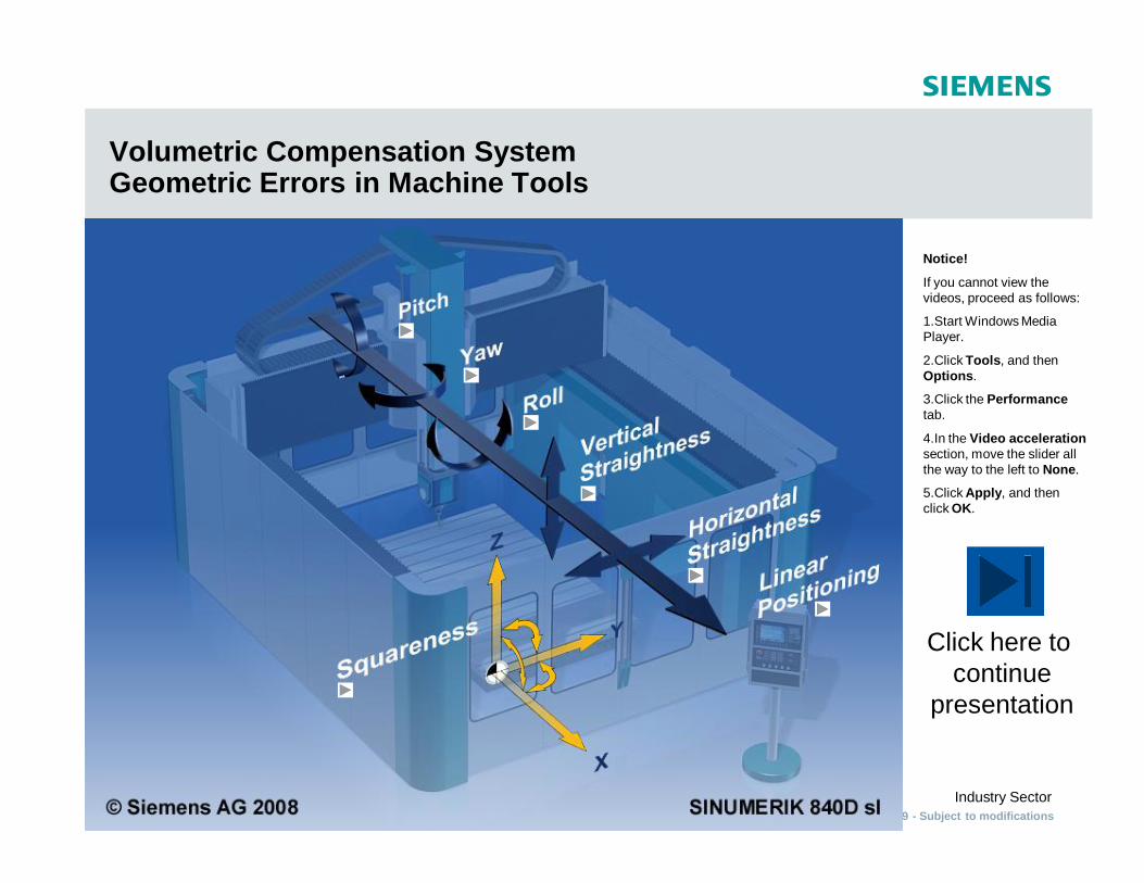
Volumetric Compensation SystemGeometric Errors in Machine Tools
Click here to continue
presentation
Notice!
If you cannot view the videos, proceed as follows:
1.Start Windows Media Player.
2.Click Tools, and then Options.
3.Click the Performancetab.
4.In the Video accelerationsection, move the slider all the way to the left to None.
5.Click Apply, and then click OK.

© Siemens AG 2009 - Subject to modificationsIndustry SectorVolumetric Compensation System
2009-01-22 Slide 4/65
PITCH
Back to master screen
© Siemens AG 2009 - Subject to modificationsIndustry SectorVolumetric Compensation System
2009-01-22 Slide 5/65
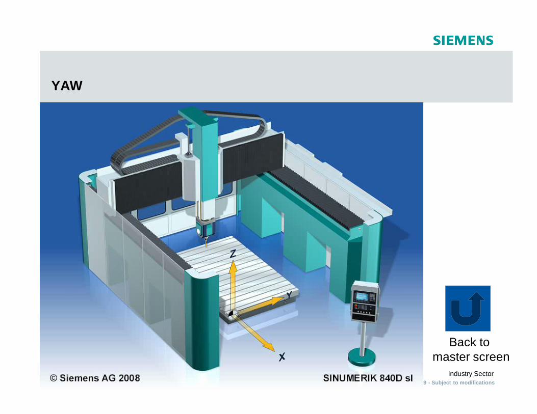
YAW
Back to master screen

© Siemens AG 2009 - Subject to modificationsIndustry SectorVolumetric Compensation System
2009-01-22 Slide 6/65
ROLL
Back to master screen

© Siemens AG 2009 - Subject to modificationsIndustry SectorVolumetric Compensation System
2009-01-22 Slide 7/65
VERTICAL STRAIGHTNESS
Back to master screen
© Siemens AG 2009 - Subject to modificationsIndustry SectorVolumetric Compensation System
2009-01-22 Slide 8/65
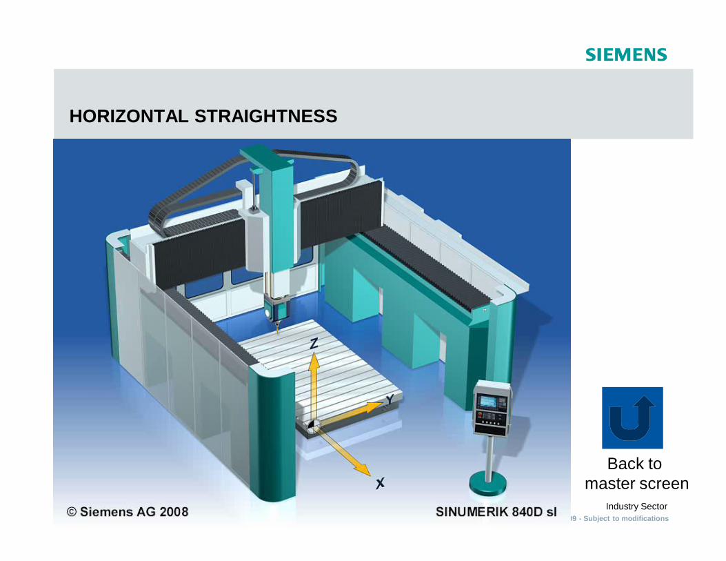
HORIZONTAL STRAIGHTNESS
Back to master screen

© Siemens AG 2009 - Subject to modificationsIndustry SectorVolumetric Compensation System
2009-01-22 Slide 9/65
LINEAR POSITIONING
Back to master screen

© Siemens AG 2009 - Subject to modificationsIndustry SectorVolumetric Compensation System
2009-01-22 Slide 10/65
SQUARENESS
Back to master screen
© Siemens AG 2009 - Subject to modificationsIndustry SectorVolumetric Compensation System
2009-01-22 Slide 11/65
Volumetric Compensation System
§ Market Requirements
© Siemens AG 2009 - Subject to modificationsIndustry SectorVolumetric Compensation System
2009-01-22 Slide 12/65
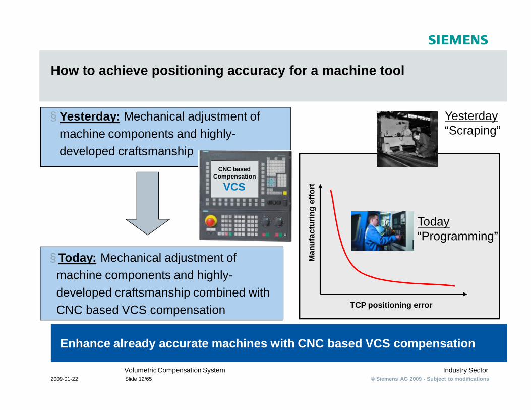
How to achieve positioning accuracy for a machine tool
Enhance already accurate machines with CNC based VCS compensation
§ Yesterday: Mechanical adjustment of machine components and highly-developed craftsmanship
TCP positioning errorM
anuf
actu
ring
effo
rt
§ Today: Mechanical adjustment of machine components and highly-developed craftsmanship combined with CNC based VCS compensation
CNC based Compensation
VCS
Yesterday“Scraping”
Today“Programming”
© Siemens AG 2009 - Subject to modificationsIndustry SectorVolumetric Compensation System
2009-01-22 Slide 13/65
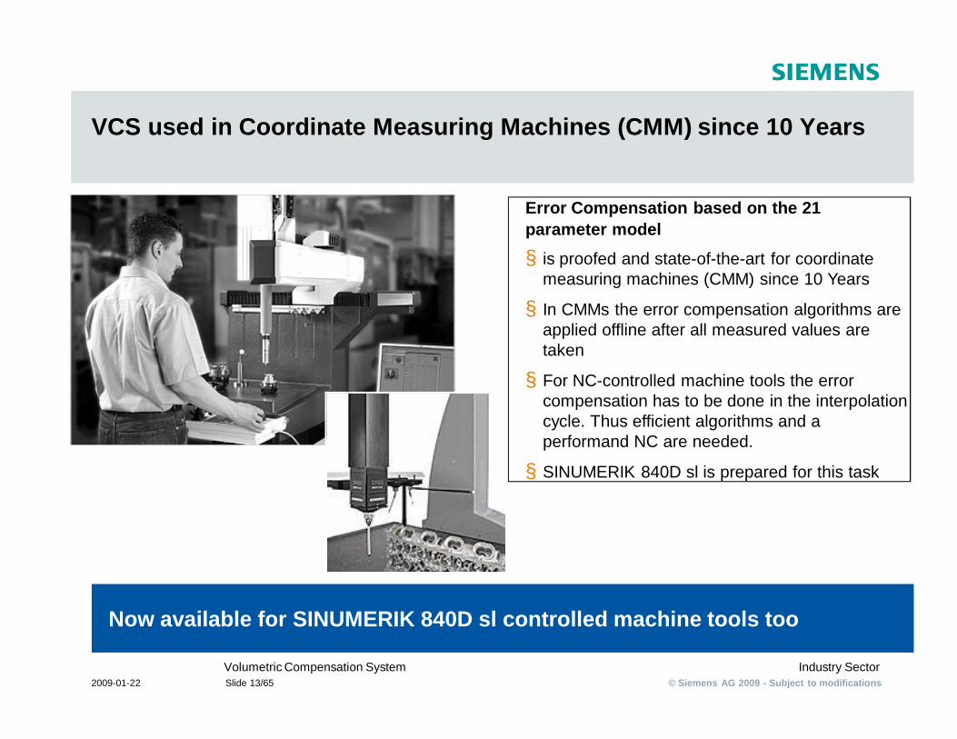
VCS used in Coordinate Measuring Machines (CMM) since 10 Years
Now available for SINUMERIK 840D sl controlled machine tools too
Error Compensation based on the 21 parameter model
§ is proofed and state-of-the-art for coordinate measuring machines (CMM) since 10 Years
§ In CMMs the error compensation algorithms are applied offline after all measured values are taken
§ For NC-controlled machine tools the error compensation has to be done in the interpolation cycle. Thus efficient algorithms and a performand NC are needed.
§ SINUMERIK 840D sl is prepared for this task
© Siemens AG 2009 - Subject to modificationsIndustry SectorVolumetric Compensation System
2009-01-22 Slide 14/65
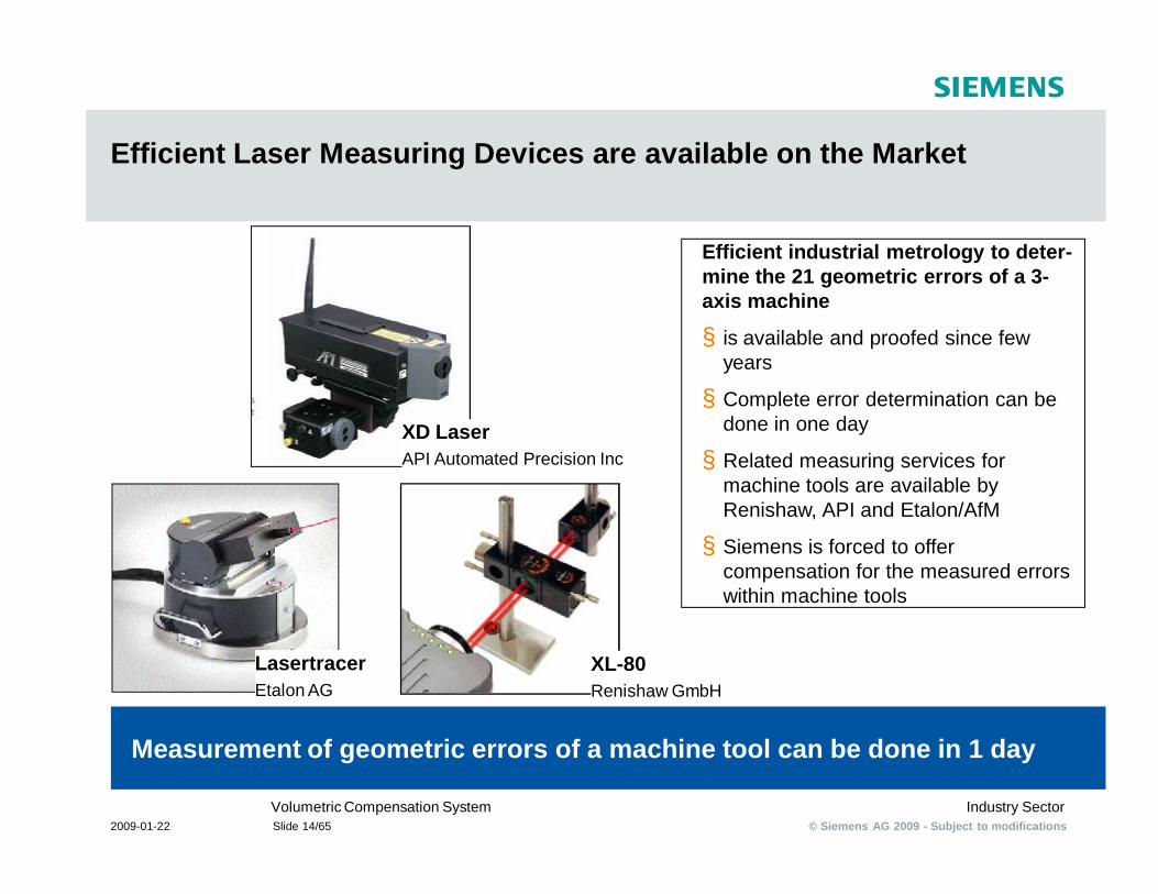
Efficient Laser Measuring Devices are available on the Market
Measurement of geometric errors of a machine tool can be done in 1 day
Efficient industrial metrology to deter-mine the 21 geometric errors of a 3-axis machine
§ is available and proofed since few years
§ Complete error determination can be done in one day
§ Related measuring services for machine tools are available by Renishaw, API and Etalon/AfM
§ Siemens is forced to offer compensation for the measured errors within machine tools
LasertracerEtalon AG
XD LaserAPI Automated Precision Inc
XL-80Renishaw GmbH
© Siemens AG 2009 - Subject to modificationsIndustry SectorVolumetric Compensation System
2009-01-22 Slide 15/65
Volumetric Compensation System
§ Objectives
© Siemens AG 2009 - Subject to modificationsIndustry SectorVolumetric Compensation System
2009-01-22 Slide 16/65
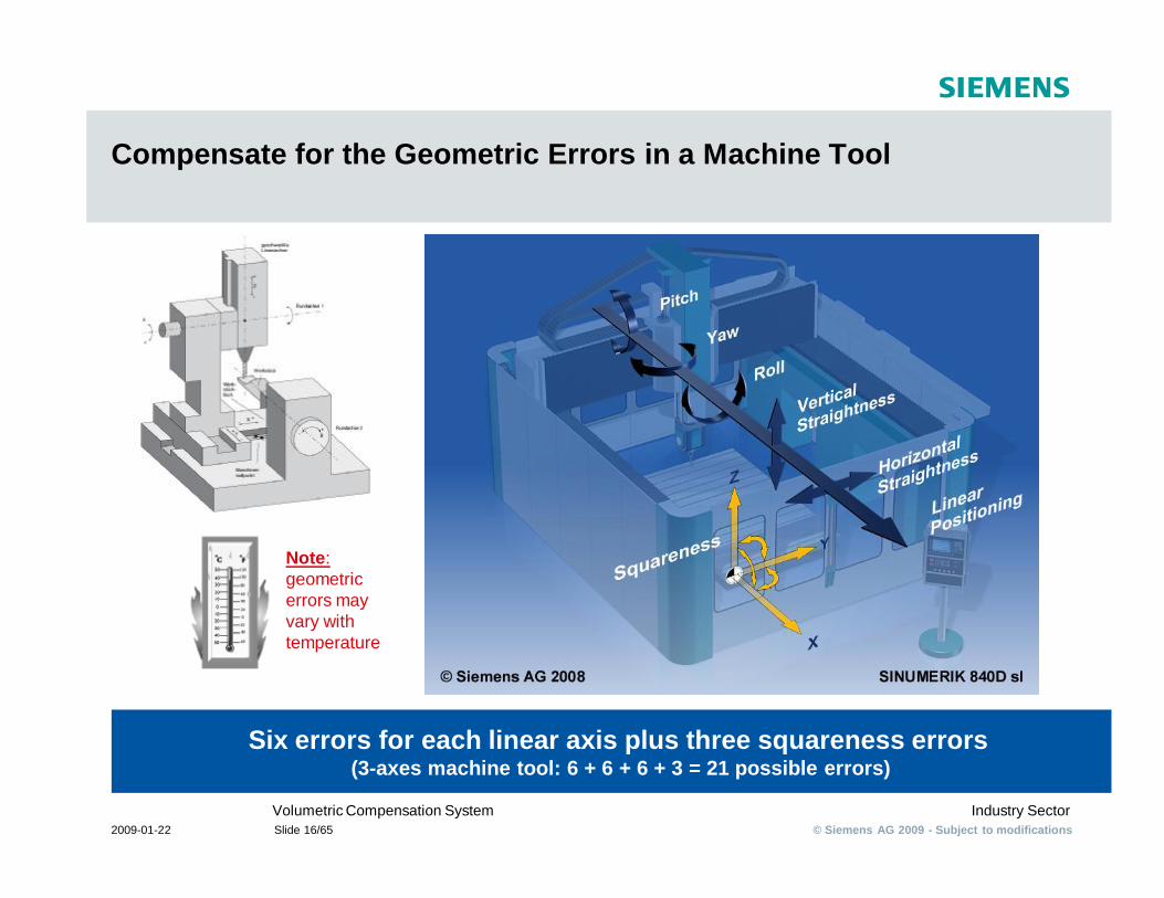
Compensate for the Geometric Errors in a Machine Tool
Six errors for each linear axis plus three squareness errors(3-axes machine tool: 6 + 6 + 6 + 3 = 21 possible errors)
Note: geometric errors may vary with temperature
© Siemens AG 2009 - Subject to modificationsIndustry SectorVolumetric Compensation System
2009-01-22 Slide 17/65
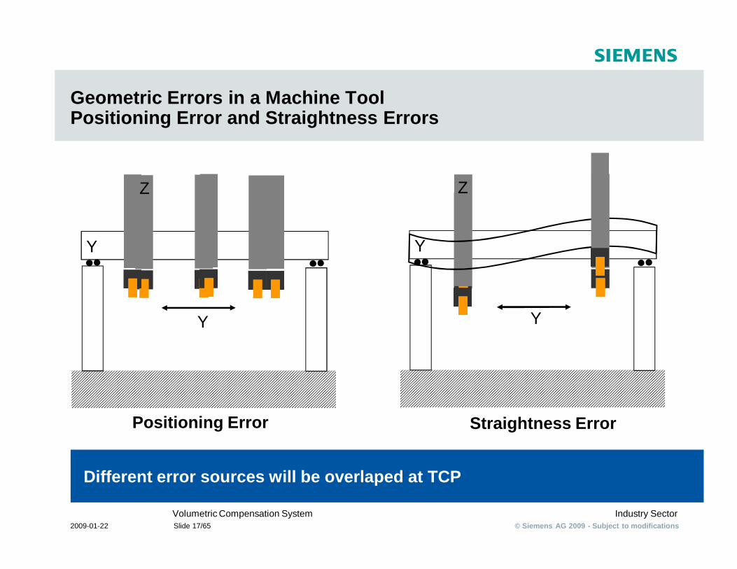
Geometric Errors in a Machine ToolPositioning Error and Straightness Errors
Different error sources will be overlaped at TCP
Y
Z
Y
Z
Positioning Error Straightness Error
Y Y
© Siemens AG 2009 - Subject to modificationsIndustry SectorVolumetric Compensation System
2009-01-22 Slide 18/65
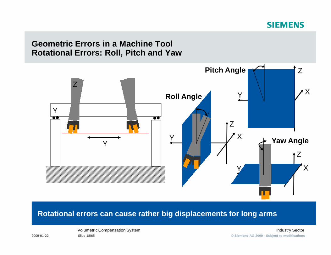
Geometric Errors in a Machine ToolRotational Errors: Roll, Pitch and Yaw
Rotational errors can cause rather big displacements for long arms
Pitch Angle
Y
Z
Y
Z
X
Roll Angle
Y
Z
X
Yaw Angle
YZ
X
Z
X
Y
© Siemens AG 2009 - Subject to modificationsIndustry SectorVolumetric Compensation System
2009-01-22 Slide 19/65
Volumetric Compensation System
§ Volumetric Error
© Siemens AG 2009 - Subject to modificationsIndustry SectorVolumetric Compensation System
2009-01-22 Slide 20/65
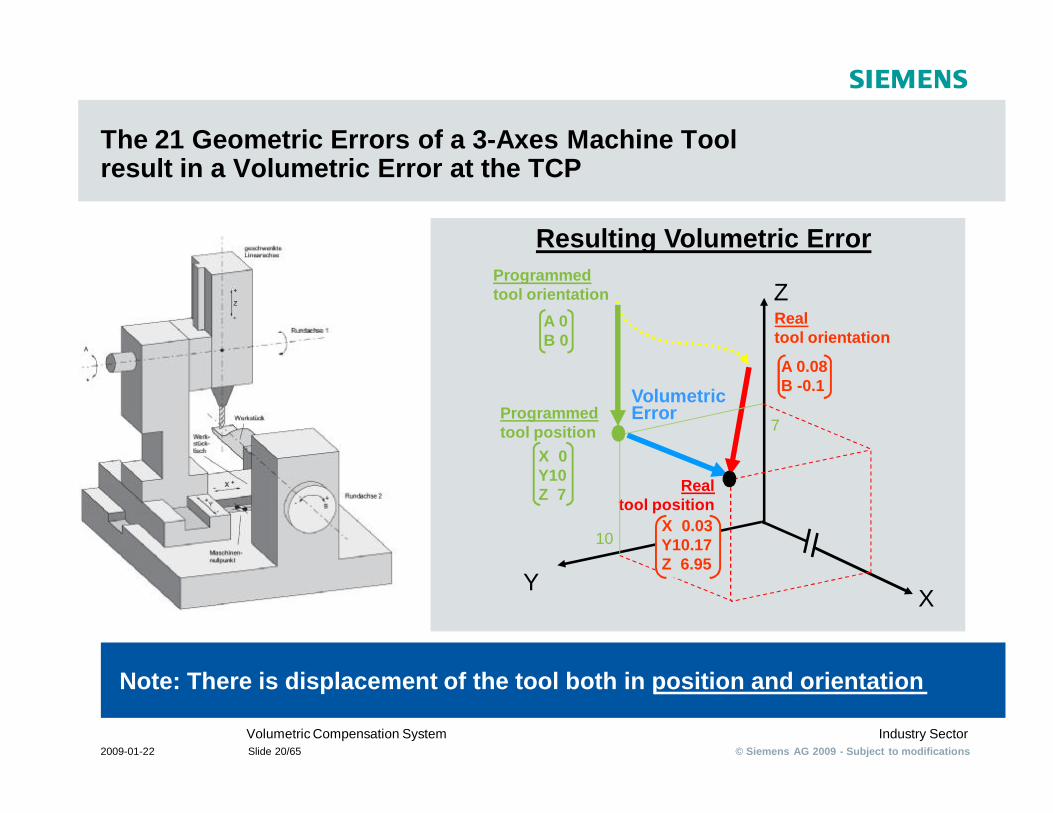
The 21 Geometric Errors of a 3-Axes Machine Toolresult in a Volumetric Error at the TCP
Note: There is displacement of the tool both in position and orientation
Resulting Volumetric ErrorProgrammedtool orientation
Realtool position
Z
YX
10
7
X 0Y10Z 7
Programmedtool position
A 0B 0
X 0.03Y10.17Z 6.95
Realtool orientation
A 0.08B -0.1Volumetric
Error
© Siemens AG 2009 - Subject to modificationsIndustry SectorVolumetric Compensation System
2009-01-22 Slide 21/65
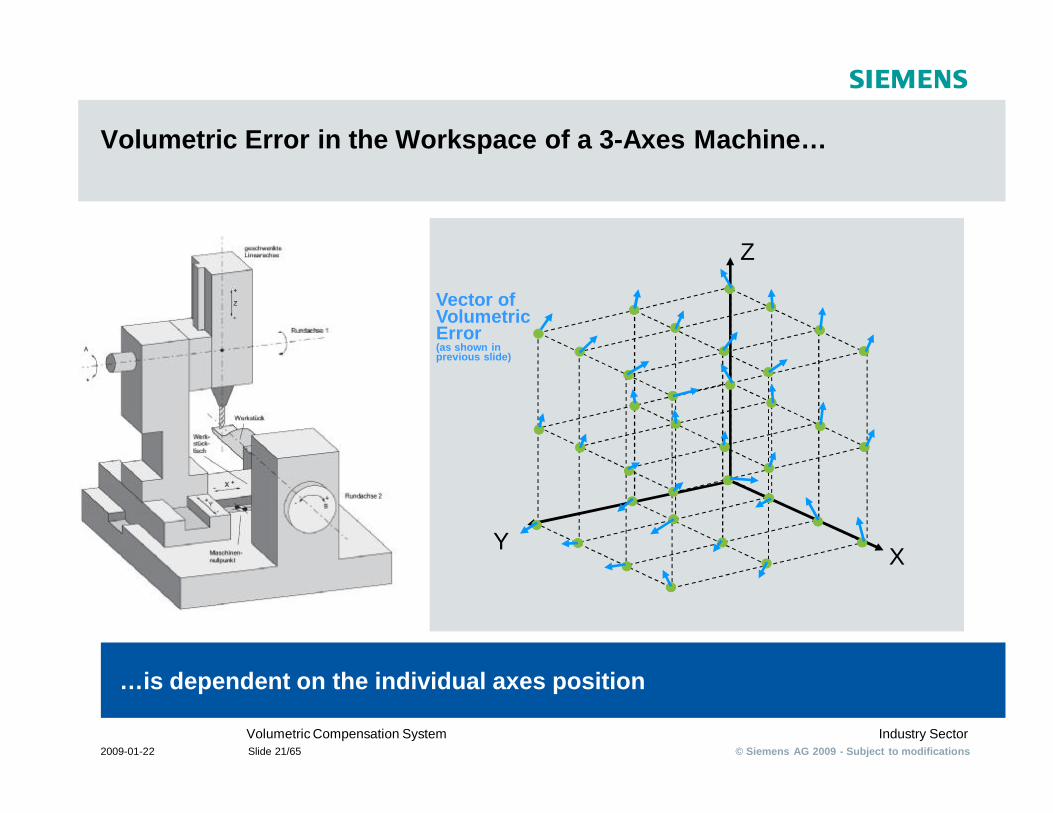
Volumetric Error in the Workspace of a 3-Axes Machine…
…is dependent on the individual axes position
Y X
Z
Vector ofVolumetric Error(as shown in previous slide)
© Siemens AG 2009 - Subject to modificationsIndustry SectorVolumetric Compensation System
2009-01-22 Slide 22/65
Volumetric Compensation System
§ Priority Market
© Siemens AG 2009 - Subject to modificationsIndustry SectorVolumetric Compensation System
2009-01-22 Slide 23/65
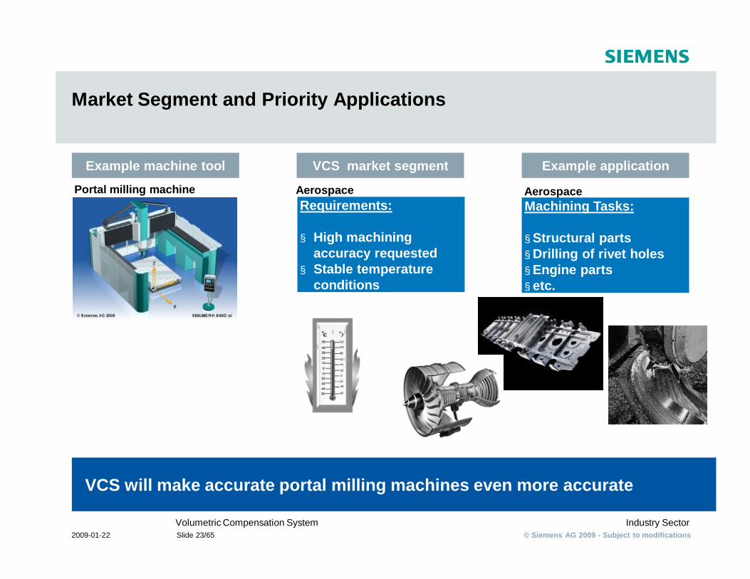
Market Segment and Priority Applications
VCS will make accurate portal milling machines even more accurate
Portal milling machine
Example applicationVCS market segmentExample machine tool
Machining Tasks:
§ Structural parts§ Drilling of rivet holes§ Engine parts§ etc.
Requirements:
§ High machining accuracy requested
§ Stable temperature conditions
Aerospace Aerospace
© Siemens AG 2009 - Subject to modificationsIndustry SectorVolumetric Compensation System
2009-01-22 Slide 24/65
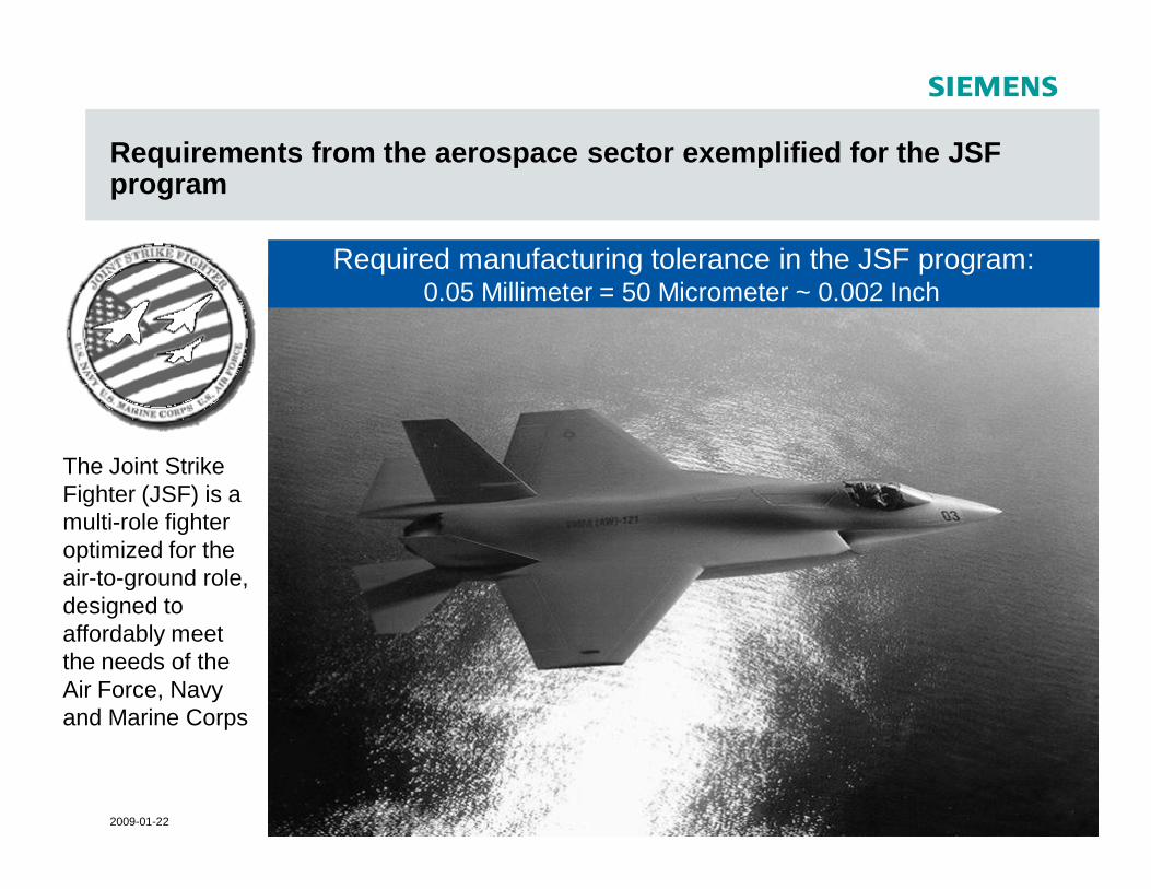
Requirements from the aerospace sector exemplified for the JSF program
The Joint Strike Fighter (JSF) is a multi-role fighter optimized for the air-to-ground role, designed to affordably meet the needs of the Air Force, Navy and Marine Corps
Required manufacturing tolerance in the JSF program: 0.05 Millimeter = 50 Micrometer ~ 0.002 Inch
© Siemens AG 2009 - Subject to modificationsIndustry SectorVolumetric Compensation System
2009-01-22 Slide 25/65
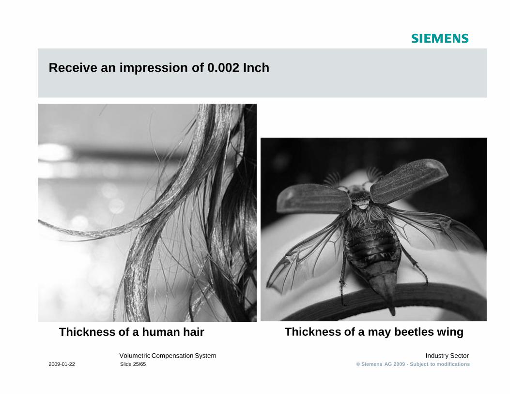
Receive an impression of 0.002 Inch
Thickness of a human hair Thickness of a may beetles wing
© Siemens AG 2009 - Subject to modificationsIndustry SectorVolumetric Compensation System
2009-01-22 Slide 26/65
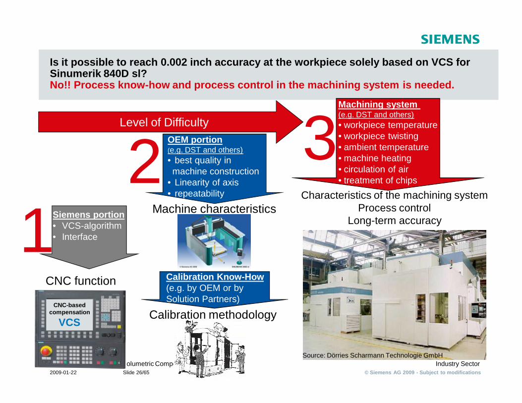
Is it possible to reach 0.002 inch accuracy at the workpiece solely based on VCS for Sinumerik 840D sl?No!! Process know-how and process control in the machining system is needed.
CNC-based compensation
VCS
CNC function
Machine characteristics12 3
Characteristics of the machining systemProcess control
Long-term accuracy
Machining system(e.g. DST and others)• workpiece temperature• workpiece twisting• ambient temperature• machine heating• circulation of air• treatment of chips
OEM portion(e.g. DST and others)• best quality in machine construction
• Linearity of axis• repeatability
Level of Difficulty
Siemens portion• VCS-algorithm• Interface
Calibration methodology
Source: Dörries Scharmann Technologie GmbH
Calibration Know-How(e.g. by OEM or by Solution Partners)
© Siemens AG 2009 - Subject to modificationsIndustry SectorVolumetric Compensation System
2009-01-22 Slide 27/65
Volumetric Compensation System
§Mode of Action
© Siemens AG 2009 - Subject to modificationsIndustry SectorVolumetric Compensation System
2009-01-22 Slide 28/65
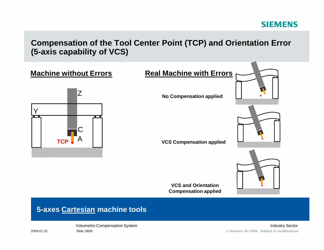
Compensation of the Tool Center Point (TCP) and Orientation Error (5-axis capability of VCS)
5-axes Cartesian machine tools
Z
Y
Machine without Errors
CA
Real Machine with Errors
No Compensation applied
VCS Compensation applied
VCS and OrientationCompensation applied
TCP
© Siemens AG 2009 - Subject to modificationsIndustry SectorVolumetric Compensation System
2009-01-22 Slide 29/65
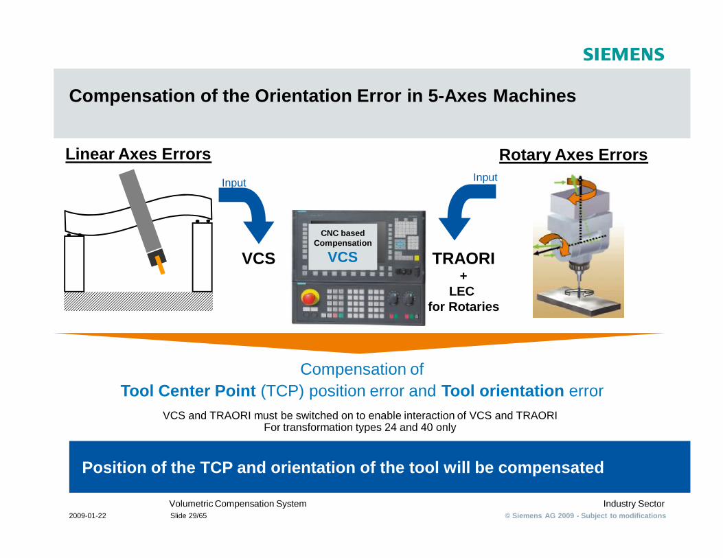
Compensation of the Orientation Error in 5-Axes Machines
VCS and TRAORI must be switched on to enable interaction of VCS and TRAORIFor transformation types 24 and 40 only
Position of the TCP and orientation of the tool will be compensated
CNC based Compensation
VCS
Linear Axes Errors Rotary Axes Errors
VCS
Input Input
TRAORI+
LEC for Rotaries
Compensation ofTool Center Point (TCP) position error and Tool orientation error
© Siemens AG 2009 - Subject to modificationsIndustry SectorVolumetric Compensation System
2009-01-22 Slide 30/65
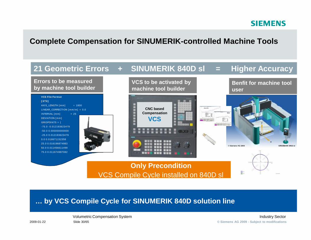
Complete Compensation for SINUMERIK-controlled Machine Tools
… by VCS Compile Cycle for SINUMERIK 840D solution line
VCS File Format
[XTX]
AXIS_LENGTH [mm] = 1800
LINEAR_CORRECTION [mm/m] = 0.0
INTERVAL [mm] = 25
DEVIATION [mm]
GRIDPOINTS = {
-75.0 -0.012193623479
-50.0 0.000000000000
-25.0 0.012193623479
0.0 0.018671152358
25.0 0.016196874983
50.0 0.011456611499
75.0 0.011674987082
21 Geometric Errors + SINUMERIK 840D sl = Higher Accuracy
Only Precondition VCS Compile Cycle installed on 840D sl
CNC based Compensation
VCS
Errors to be measured by machine tool builder
VCS to be activated by machine tool builder
Benfit for machine tool user
© Siemens AG 2009 - Subject to modificationsIndustry SectorVolumetric Compensation System
2009-01-22 Slide 31/65
Volumetric Compensation System
§ Interpolation of 2 VCS Files
© Siemens AG 2009 - Subject to modificationsIndustry SectorVolumetric Compensation System
2009-01-22 Slide 32/65
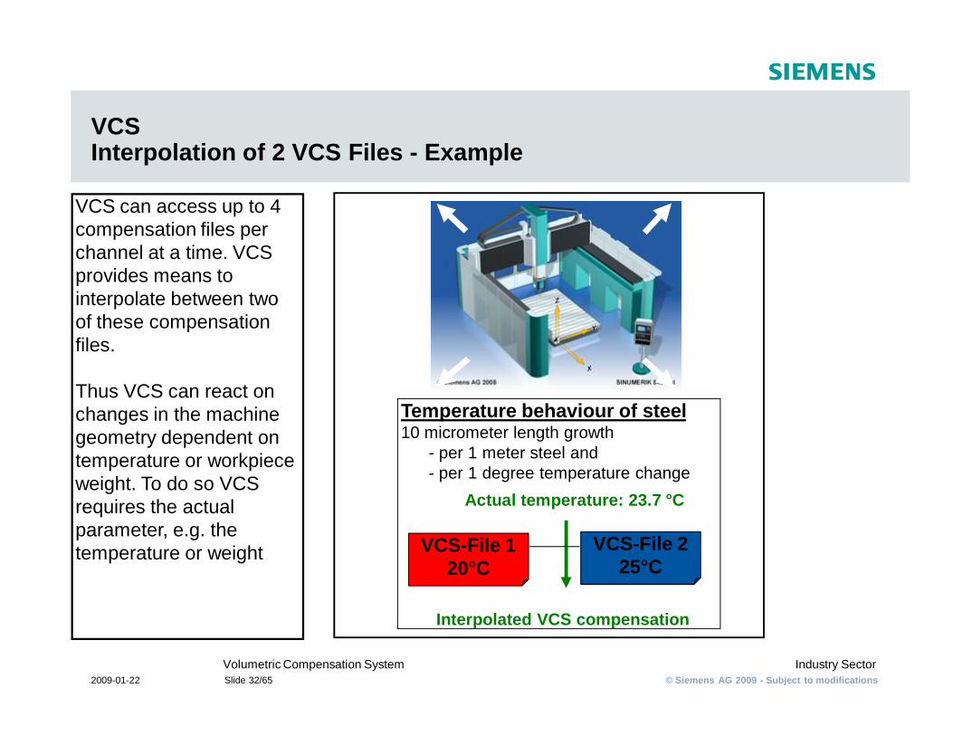
VCS Interpolation of 2 VCS Files - Example
VCS can access up to 4 compensation files per channel at a time. VCS provides means to interpolate between two of these compensation files.
Thus VCS can react on changes in the machine geometry dependent on temperature or workpiece weight. To do so VCS requires the actual parameter, e.g. the temperature or weight
Temperature behaviour of steel10 micrometer length growth
- per 1 meter steel and- per 1 degree temperature change
VCS-File 120°C
VCS-File 225°C
Actual temperature: 23.7 °C
Interpolated VCS compensation
© Siemens AG 2009 - Subject to modificationsIndustry SectorVolumetric Compensation System
2009-01-22 Slide 33/65
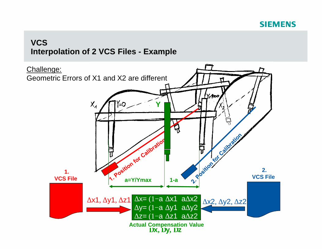
VCS Interpolation of 2 VCS Files - Example
1.VCS File
2.VCS File
∆x1, ∆y1, ∆z1 ∆x2, ∆y2, ∆z2
∆x, ∆y, ∆z
a=Y/Ymax 1-a
∆x= (1−a)∆x1+a∆x2
Y
∆y= (1−a)∆y1+a∆y2∆z= (1−a)∆z1+a∆z2
Actual Compensation Value
Challenge:Geometric Errors of X1 and X2 are different
© Siemens AG 2009 - Subject to modificationsIndustry SectorVolumetric Compensation System
2009-01-22 Slide 34/65
Volumetric Compensation System
§ Market Access
© Siemens AG 2009 - Subject to modificationsIndustry SectorVolumetric Compensation System
2009-01-22 Slide 35/65
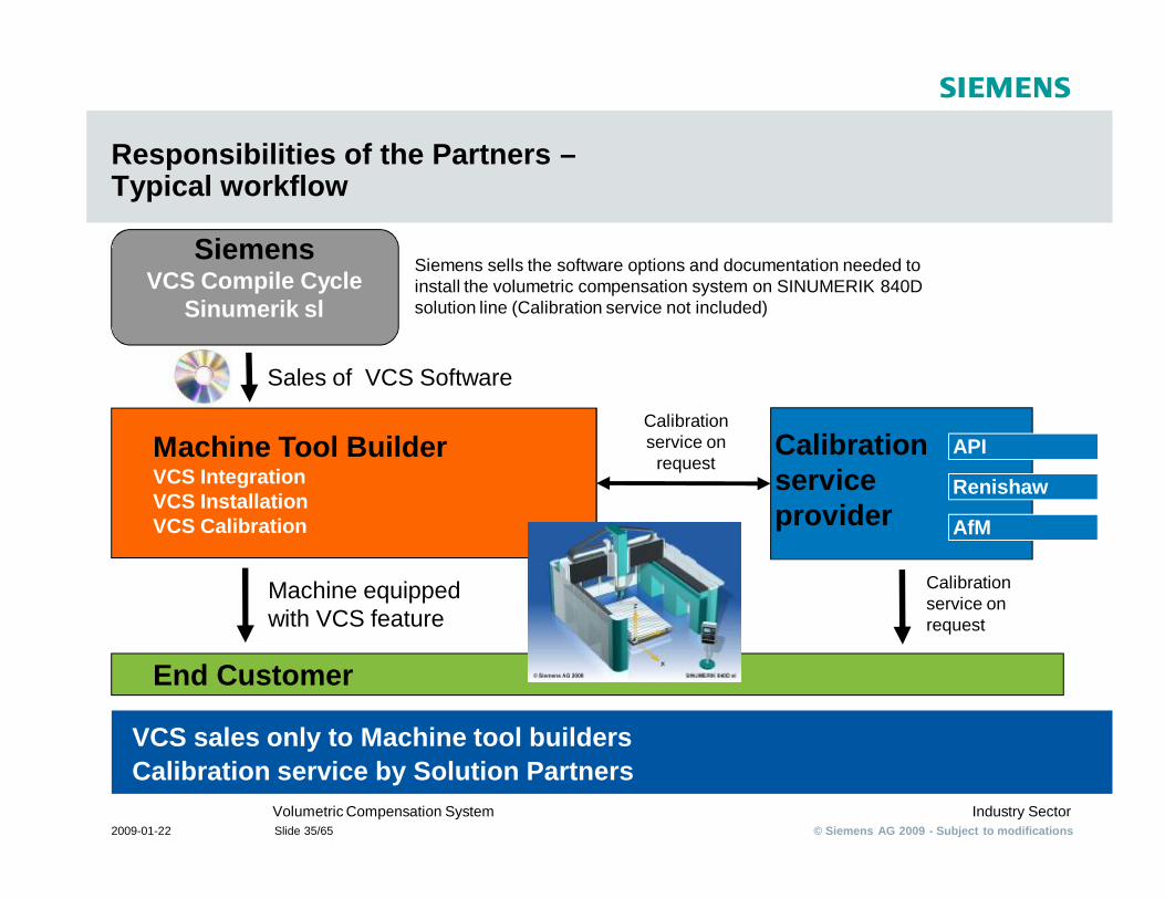
Responsibilities of the Partners –Typical workflow
VCS sales only to Machine tool buildersCalibration service by Solution Partners
Machine Tool BuilderVCS IntegrationVCS InstallationVCS Calibration
End Customer
Calibration serviceprovider
Machine equipped with VCS feature
Siemens sells the software options and documentation needed to install the volumetric compensation system on SINUMERIK 840D solution line (Calibration service not included)
SiemensVCS Compile Cycle
Sinumerik sl
AfM
API
Renishaw
Sales of VCS Software
Calibration service on request
Calibration service on
request
© Siemens AG 2009 - Subject to modificationsIndustry SectorVolumetric Compensation System
2009-01-22 Slide 36/65
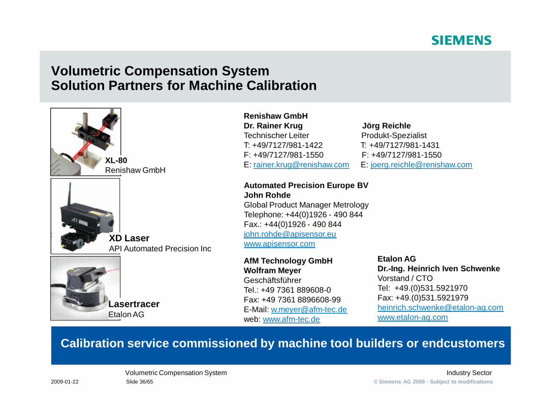
Volumetric Compensation SystemSolution Partners for Machine Calibration
Calibration service commissioned by machine tool builders or endcustomers
LasertracerEtalon AG
XD LaserAPI Automated Precision Inc
XL-80Renishaw GmbH
Renishaw GmbHDr. Rainer Krug Jörg ReichleTechnischer Leiter Produkt-SpezialistT: +49/7127/981-1422 T: +49/7127/981-1431F: +49/7127/981-1550 F: +49/7127/981-1550E: [email protected] E: [email protected]
Automated Precision Europe BVJohn RohdeGlobal Product Manager Metrology Telephone: +44(0)1926 - 490 844Fax.: +44(0)1926 - 490 844 [email protected]
AfM Technology GmbH Wolfram Meyer GeschäftsführerTel.: +49 7361 889608-0Fax: +49 7361 8896608-99E-Mail: [email protected]: www.afm-tec.de
Etalon AG Dr.-Ing. Heinrich Iven SchwenkeVorstand / CTOTel: +49.(0)531.5921970Fax: +49.(0)[email protected]
© Siemens AG 2009 - Subject to modificationsIndustry SectorVolumetric Compensation System
2009-01-22 Slide 37/65
Volumetric Compensation System
§ Set-Up Process
© Siemens AG 2009 - Subject to modificationsIndustry SectorVolumetric Compensation System
2009-01-22 Slide 38/65
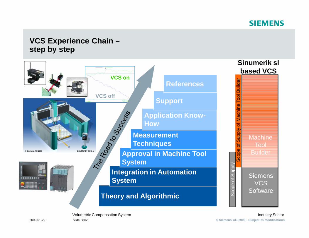
VCS Experience Chain –step by step
Theory and Algorithmic
Integration in Automation System
Approval in Machine Tool System
Measurement Techniques
Application Know-How
Support
References
Siemens VCS
Software
Sinumerik sl based VCS
Machine Tool
Builder
Scop
e of
Sup
ply
of M
achi
ne T
ool B
uild
erSc
ope
of S
uppl
y
VCS off
VCS on
© Siemens AG 2009 - Subject to modificationsIndustry SectorVolumetric Compensation System
2009-01-22 Slide 39/65
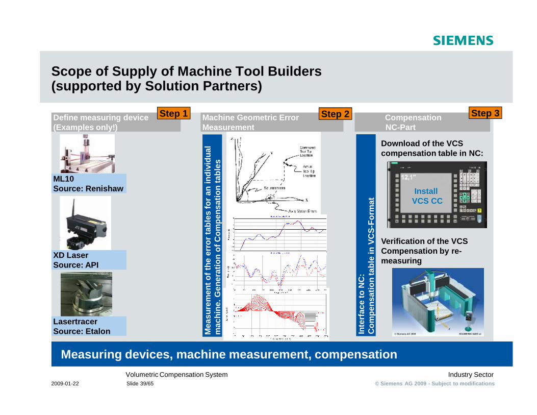
Scope of Supply of Machine Tool Builders (supported by Solution Partners)
Measuring devices, machine measurement, compensation
Define measuring device(Examples only!)
Machine Geometric ErrorMeasurement
Compensation NC-Part
Step 1 Step 3
XD LaserSource: API
ML10Source: Renishaw
LasertracerSource: Etalon
Step 2
Mea
sure
men
t of t
he e
rror
tabl
es fo
r an
indi
vidu
al
mac
hine
. Gen
erat
ion
of C
ompe
nsat
ion
tabl
es
Inte
rfac
e to
NC
: C
ompe
nsat
ion
tabl
e in
VC
S-Fo
rmat
Download of the VCS compensation table in NC:
Verification of the VCS Compensation by re-measuring
Install VCS CC
© Siemens AG 2009 - Subject to modificationsIndustry SectorVolumetric Compensation System
2009-01-22 Slide 40/65
Volumetric Compensation System
§ Results
© Siemens AG 2009 - Subject to modificationsIndustry SectorVolumetric Compensation System
2009-01-22 Slide 41/65
Volumetric Compensation System
§ More than 10 machine tools compensated successful so far
§ Summary of reference projects available on request
© Siemens AG 2009 - Subject to modificationsIndustry SectorVolumetric Compensation System
2009-01-22 Slide 42/65
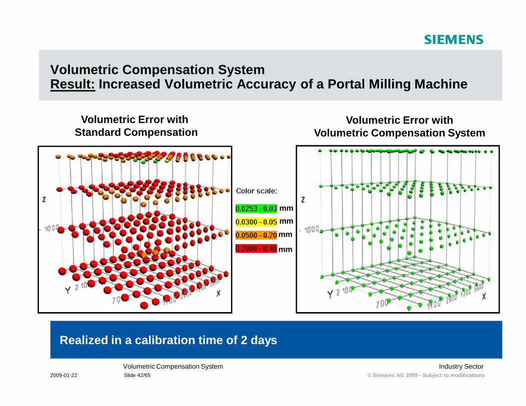
Volumetric Compensation SystemResult: Increased Volumetric Accuracy of a Portal Milling Machine
Realized in a calibration time of 2 days
Volumetric Error with Standard Compensation
Volumetric Error withVolumetric Compensation System
mmmmmm
mm
Volumetric Compensation System
Name: Dr. Jochen Bretschneider
Department: Industry Sector
Address: MC MT P 3
Phone: +49 (9131) 98-4134
Mail: [email protected]
Thank you
VC
S_Technical_D
escription_Sales_January_2009_english.ppt
SINUMERIKVolumetric Compensation System
Secure your futurewith innovative manufacturing
© Siemens AG 2009 - Subject to modificationsIndustry SectorVolumetric Compensation System
2009-01-22 Slide 44/65
Volumetric Compensation System
§ FAQs
© Siemens AG 2009 - Subject to modificationsIndustry SectorVolumetric Compensation System
2009-01-22 Slide 45/65
Volumetric Compensation System
§ Can I build cheap incorrect machines and VCS will correct?
§ No. High repeatability of the machine is required.
© Siemens AG 2009 - Subject to modificationsIndustry SectorVolumetric Compensation System
2009-01-22 Slide 46/65
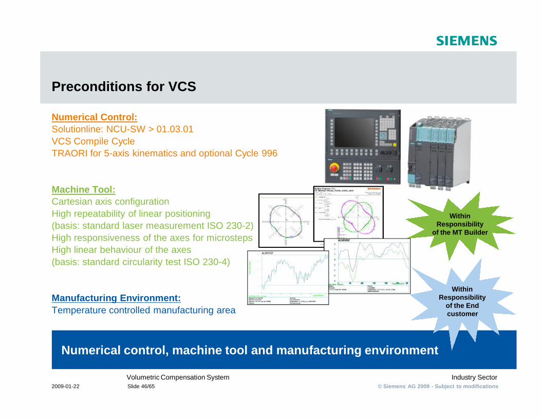
Preconditions for VCS
Numerical Control:Solutionline: NCU-SW > 01.03.01VCS Compile CycleTRAORI for 5-axis kinematics and optional Cycle 996
Machine Tool:Cartesian axis configurationHigh repeatability of linear positioning (basis: standard laser measurement ISO 230-2)High responsiveness of the axes for microstepsHigh linear behaviour of the axes(basis: standard circularity test ISO 230-4)
Manufacturing Environment:Temperature controlled manufacturing area
Numerical control, machine tool and manufacturing environment
Within Responsibility
of the MT Builder
Within Responsibility
of the End customer
© Siemens AG 2009 - Subject to modificationsIndustry SectorVolumetric Compensation System
2009-01-22 Slide 47/65
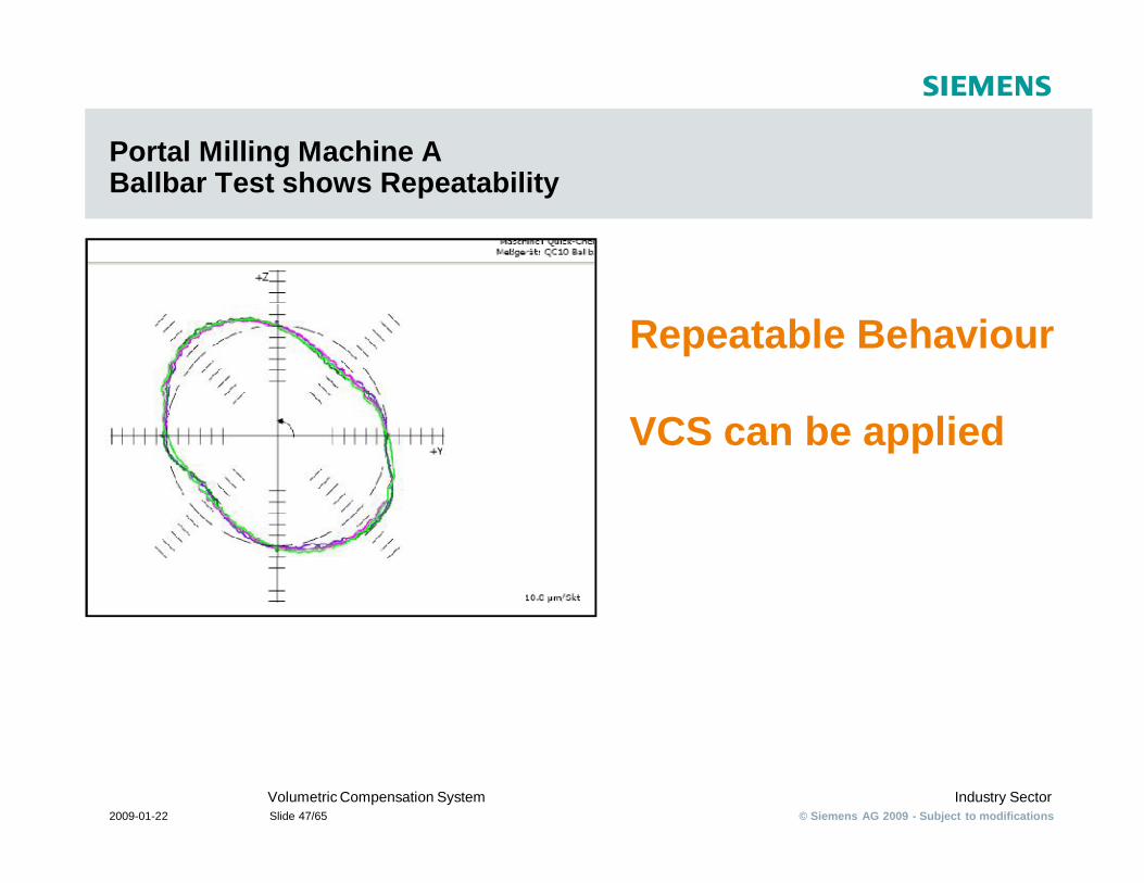
Portal Milling Machine A Ballbar Test shows Repeatability
Repeatable Behaviour
VCS can be applied
© Siemens AG 2009 - Subject to modificationsIndustry SectorVolumetric Compensation System
2009-01-22 Slide 48/65
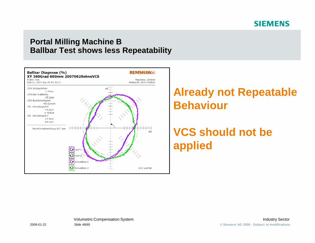
Portal Milling Machine B Ballbar Test shows less Repeatability
Already not Repeatable Behaviour
VCS should not be applied
© Siemens AG 2009 - Subject to modificationsIndustry SectorVolumetric Compensation System
2009-01-22 Slide 49/65
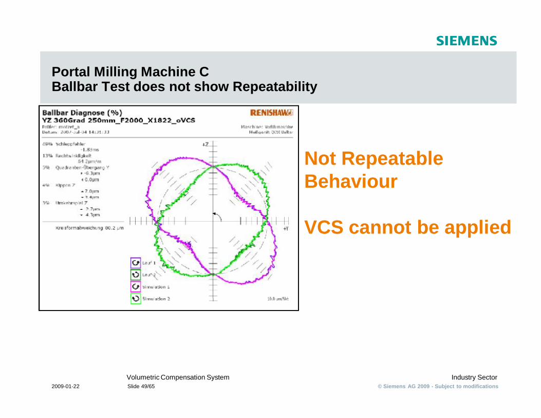
Portal Milling Machine C Ballbar Test does not show Repeatability
Not Repeatable Behaviour
VCS cannot be applied
© Siemens AG 2009 - Subject to modificationsIndustry SectorVolumetric Compensation System
2009-01-22 Slide 50/65
Volumetric Compensation System
§ Influence of changing Temperature
© Siemens AG 2009 - Subject to modificationsIndustry SectorVolumetric Compensation System
2009-01-22 Slide 51/65
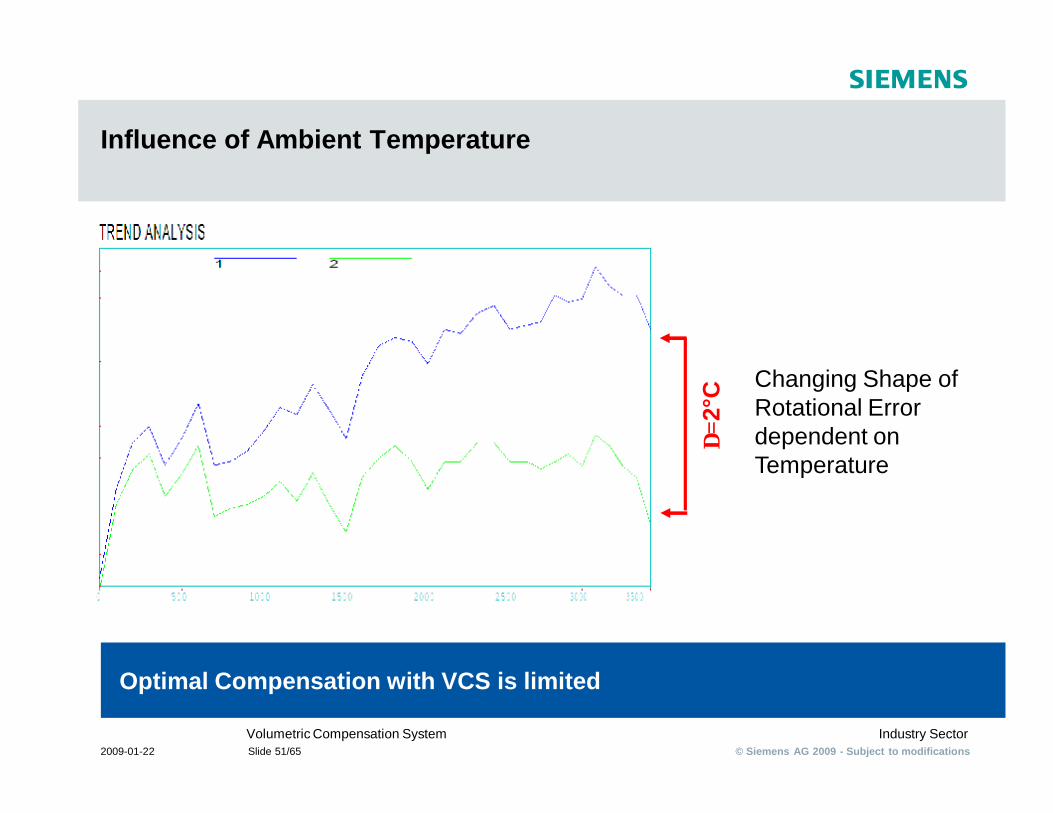
Influence of Ambient Temperature
∆=2
°C
Changing Shape of Rotational Error dependent on Temperature
Optimal Compensation with VCS is limited

© Siemens AG 2009 - Subject to modificationsIndustry SectorVolumetric Compensation System
2009-01-22 Slide 52/65
Volumetric Compensation SystemPosition Error caused by Solar Radiation
T
Optimal Compensation with VCS is limited
Changing Position Error dependent on Temperature
© Siemens AG 2009 - Subject to modificationsIndustry SectorVolumetric Compensation System
2009-01-22 Slide 53/65
Volumetric Compensation System
§ Difference to existing Compensations
© Siemens AG 2009 - Subject to modificationsIndustry SectorVolumetric Compensation System
2009-01-22 Slide 54/65
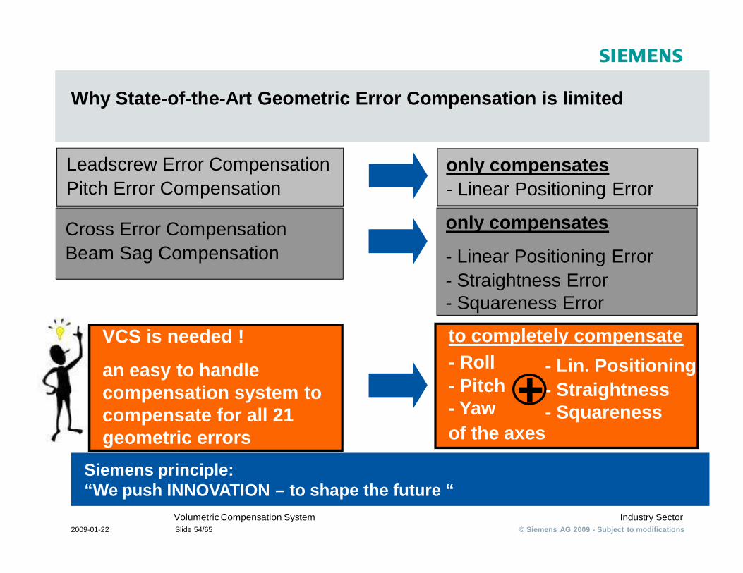
Why State-of-the-Art Geometric Error Compensation is limited
Siemens principle:“We push INNOVATION – to shape the future “
Leadscrew Error CompensationPitch Error Compensation
Cross Error CompensationBeam Sag Compensation
only compensates- Linear Positioning Error
only compensates
- Linear Positioning Error- Straightness Error- Squareness Error
to completely compensate - Roll- Pitch- Yaw of the axes
VCS is needed !
an easy to handle compensation system to compensate for all 21 geometric errors
- Lin. Positioning- Straightness- Squareness
© Siemens AG 2009 - Subject to modificationsIndustry SectorVolumetric Compensation System
2009-01-22 Slide 55/65
Volumetric Compensation System
§ Which SW options are needed in detail?
© Siemens AG 2009 - Subject to modificationsIndustry SectorVolumetric Compensation System
2009-01-22 Slide 56/65
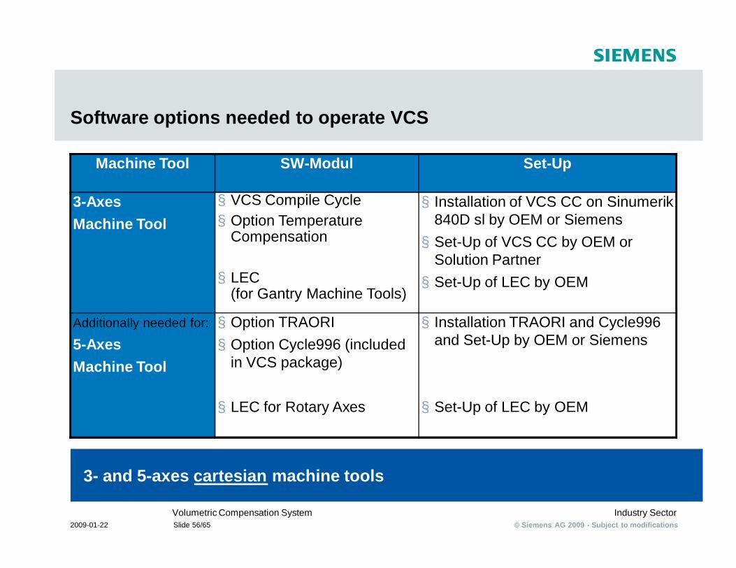
Software options needed to operate VCS
3- and 5-axes cartesian machine tools
Machine Tool SW-Modul Set-Up
3-Axes Machine Tool
§ VCS Compile Cycle§ Option Temperature
Compensation
§ LEC (for Gantry Machine Tools)
§ Installation of VCS CC on Sinumerik 840D sl by OEM or Siemens§ Set-Up of VCS CC by OEM or
Solution Partner§ Set-Up of LEC by OEM
Additionally needed for:
5-Axes Machine Tool
§ Option TRAORI§ Option Cycle996 (included
in VCS package)
§ LEC for Rotary Axes
§ Installation TRAORI and Cycle996 and Set-Up by OEM or Siemens
§ Set-Up of LEC by OEM
© Siemens AG 2009 - Subject to modificationsIndustry SectorVolumetric Compensation System
2009-01-22 Slide 57/65
Volumetric Compensation System
§ Which Compensations are conducted by VCS in detail?
© Siemens AG 2009 - Subject to modificationsIndustry SectorVolumetric Compensation System
2009-01-22 Slide 58/65
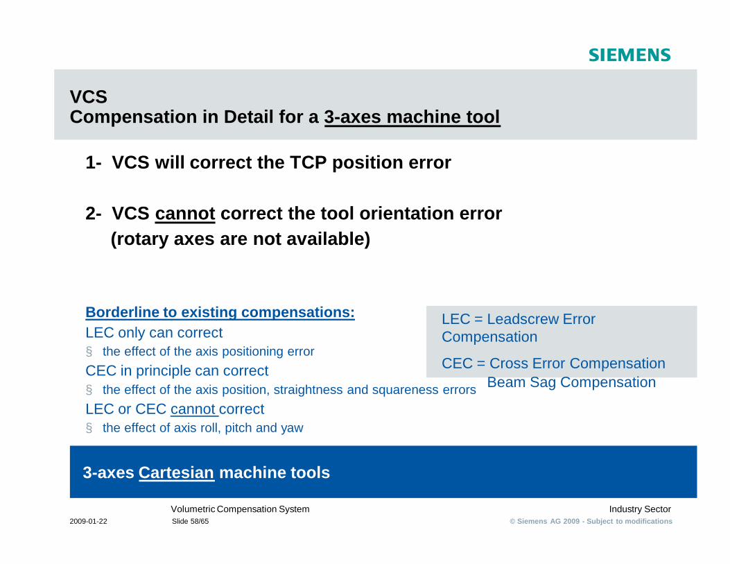
VCSCompensation in Detail for a 3-axes machine tool
1- VCS will correct the TCP position error
2- VCS cannot correct the tool orientation error (rotary axes are not available)
Borderline to existing compensations:LEC only can correct§ the effect of the axis positioning error CEC in principle can correct§ the effect of the axis position, straightness and squareness errorsLEC or CEC cannot correct§ the effect of axis roll, pitch and yaw
3-axes Cartesian machine tools
LEC = Leadscrew Error Compensation
CEC = Cross Error CompensationBeam Sag Compensation
© Siemens AG 2009 - Subject to modificationsIndustry SectorVolumetric Compensation System
2009-01-22 Slide 59/65
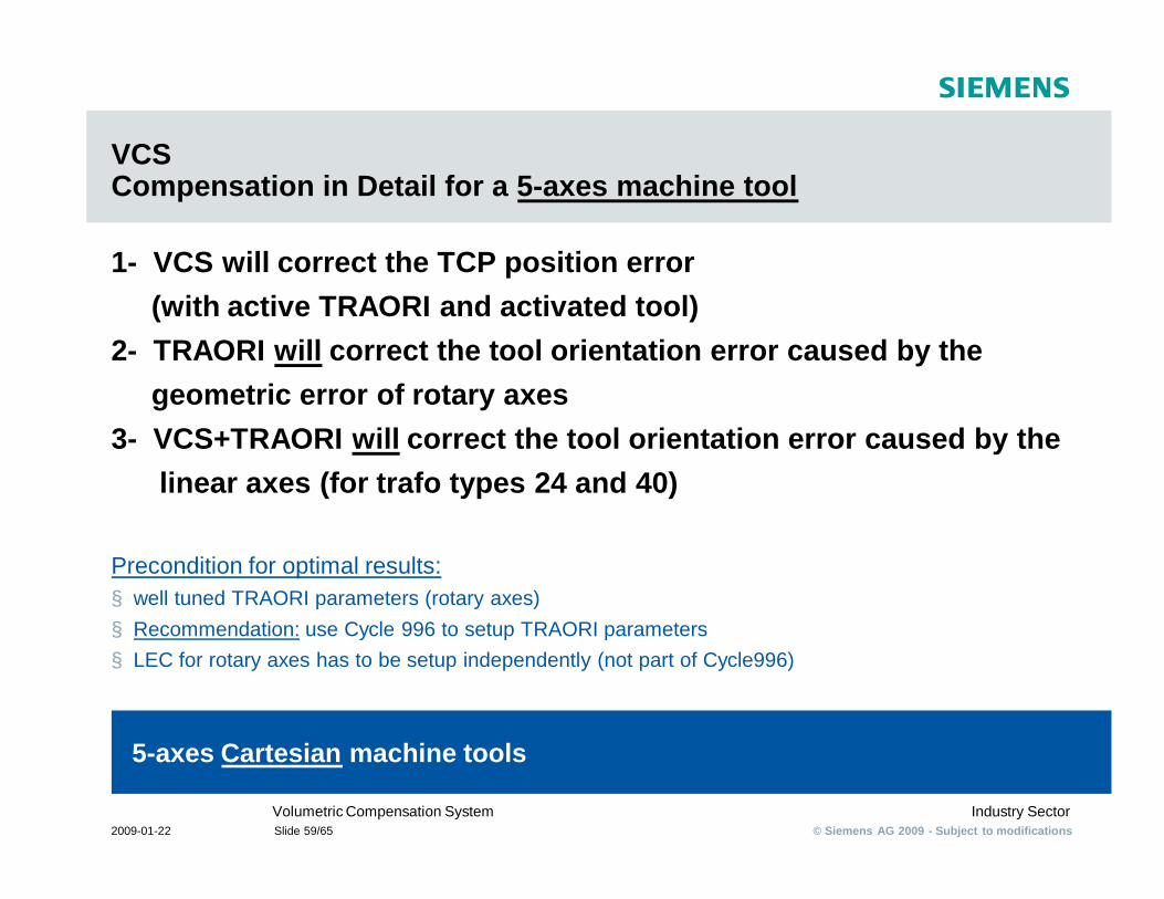
VCSCompensation in Detail for a 5-axes machine tool
1- VCS will correct the TCP position error (with active TRAORI and activated tool)
2- TRAORI will correct the tool orientation error caused by the geometric error of rotary axes
3- VCS+TRAORI will correct the tool orientation error caused by the linear axes (for trafo types 24 and 40)
Precondition for optimal results:§ well tuned TRAORI parameters (rotary axes)§ Recommendation: use Cycle 996 to setup TRAORI parameters§ LEC for rotary axes has to be setup independently (not part of Cycle996)
5-axes Cartesian machine tools
© Siemens AG 2009 - Subject to modificationsIndustry SectorVolumetric Compensation System
2009-01-22 Slide 60/65
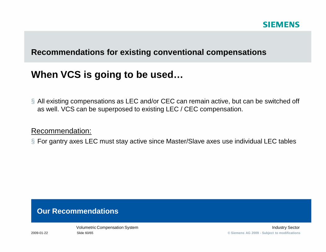
Recommendations for existing conventional compensations
When VCS is going to be used…
§ All existing compensations as LEC and/or CEC can remain active, but can be switched off as well. VCS can be superposed to existing LEC / CEC compensation.
Recommendation:§ For gantry axes LEC must stay active since Master/Slave axes use individual LEC tables
Our Recommendations
© Siemens AG 2009 - Subject to modificationsIndustry SectorVolumetric Compensation System
2009-01-22 Slide 61/65
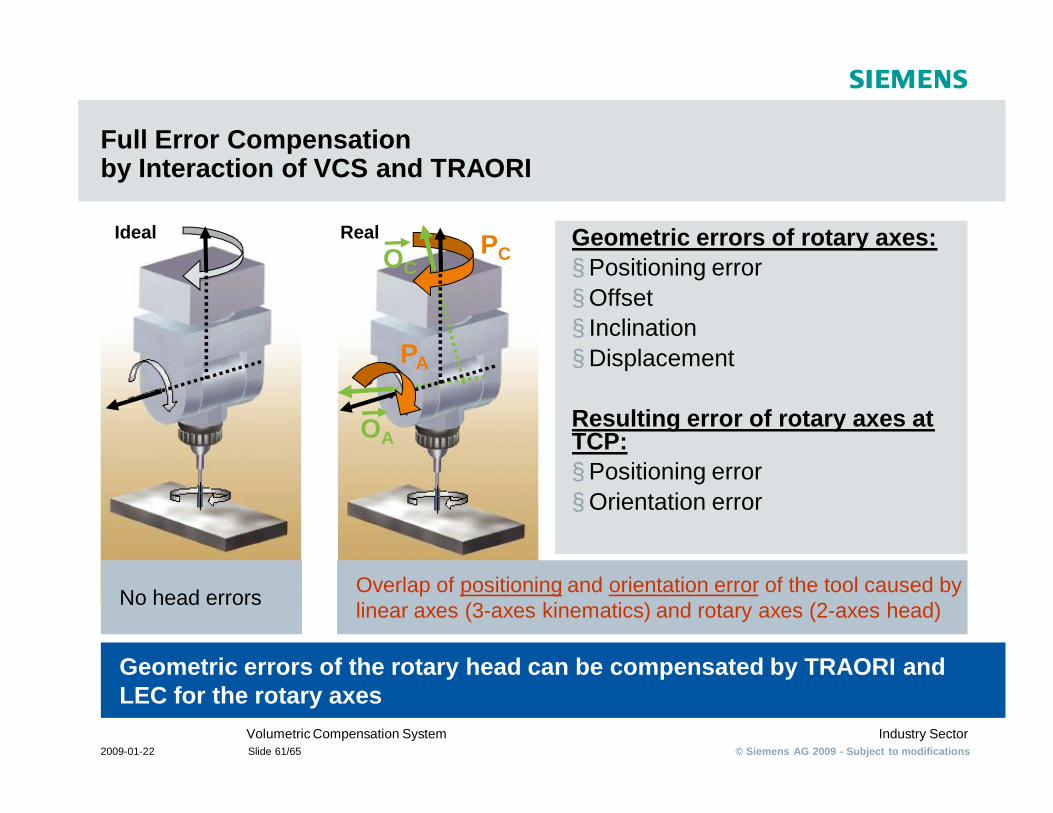
Full Error Compensationby Interaction of VCS and TRAORI
Geometric errors of the rotary head can be compensated by TRAORI and LEC for the rotary axes
Geometric errors of rotary axes:§ Positioning error§ Offset § Inclination § Displacement
Resulting error of rotary axes at TCP:§ Positioning error§ Orientation error
Ideal
No head errors Overlap of positioning and orientation error of the tool caused by linear axes (3-axes kinematics) and rotary axes (2-axes head)
Real
OA
OCPC
PA
© Siemens AG 2009 - Subject to modificationsIndustry SectorVolumetric Compensation System
2009-01-22 Slide 62/65
Volumetric Compensation System
§ Some more Results
© Siemens AG 2009 - Subject to modificationsIndustry SectorVolumetric Compensation System
2009-01-22 Slide 63/65
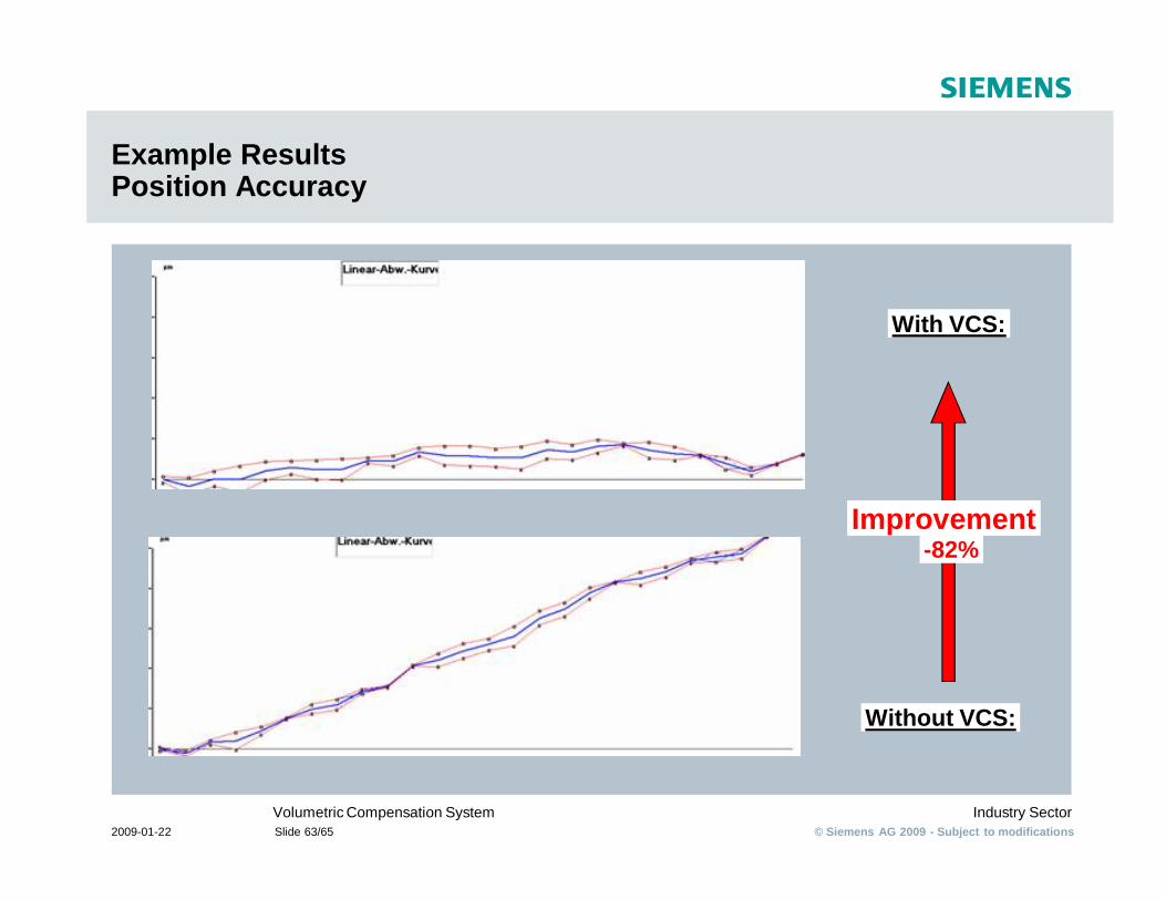
Example ResultsPosition Accuracy
Without VCS:
With VCS:
Improvement-82%
© Siemens AG 2009 - Subject to modificationsIndustry SectorVolumetric Compensation System
2009-01-22 Slide 64/65
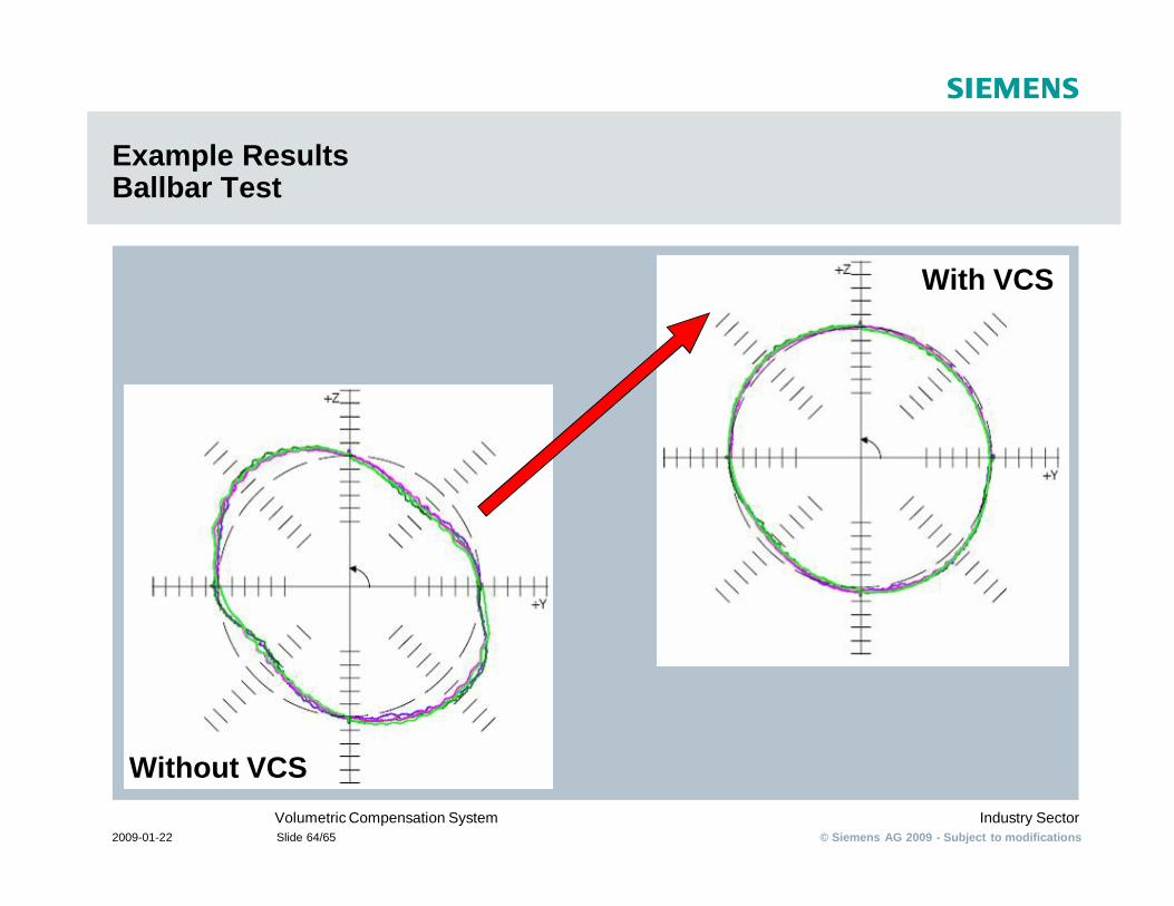
Example Results Ballbar Test
Without VCS
With VCS
© Siemens AG 2009 - Subject to modificationsIndustry SectorVolumetric Compensation System
2009-01-22 Slide 65/65
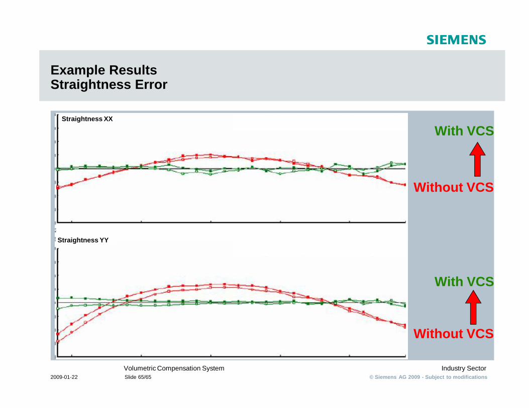
Example Results Straightness Error
Without VCS
With VCS
With VCS
Without VCS
Straightness XX
Straightness YY