Embed Size (px)
Citation preview

Volume V:Duraplus
®
Air-line System
Industrial TechnicalManual Series
DURAPLUS ® AIR-LINE SYSTEM
A l ightweight corros ion res i s t antcompressed a ir d i s t r ibut ion sys temfrom IPEX
F I R S T E D I T I O N
IPEX Duraplus® Air-line
Industrial Technical Manual Series Vol. V. 1st Edition
© 2006 by IPEX

About IPEXAt IPEX, we have been manufacturing non-metallic pipe and fittings since 1951. We formulate most of our compoundsourselves, and maintain strict quality control during production. Our products are made available for customers thanks to anetwork of regional stocking locations throughout North America. We offer a wide variety of systems including complete linesof piping, fittings, valves and custom-fabricated items.
More importantly, we are committed to meeting our customers’ needs. As a leader in the plastic piping industry, IPEXcontinually develops new products, modernizes manufacturing facilities and acquires innovative process technology. Inaddition, our staff take pride in their work, making available to customers their extensive thermoplastic knowledge and fieldexperience. For specific details about any IPEX product, contact our customer service department (contact information islisted on the back cover).

3
SAFETY ALERTS
AREAS OF USE
Air-line must be used downstream from the receiver oraftercooler only.
Care must be taken to avoid overheating air-line. Metalpipe must be used between compressor and receiver andat any other part of a system where conditions exceedthose permissible for air-line. Refer to page 14.
Air-line should not be connected directly to vibratingmachinery. Flexible couplings should be incorporated toabsorb vibrations.
INSTALLATION PRECAUTIONS
Air-line pipe must not be threaded. Refer to page 22.
Lubricators must only be installed at the downstreamextremities of the system.
Air-line must not be bent. Standard elbows and moldedbends are available throughout the size range.
Certain types of flexible hoses contain plasticizers whichare harmful to air-line piping. Therefore the suitability ofhoses which are to be installed upstream of the air-linesystem must be checked with IPEX prior to installation.
Purge new compressors and ancillary equipment,including new steel piping, prior to connecting to theair-line system.
INSPECTION AND TESTING
After installation, the air-line system must be inspected forexternal damage in the form of cuts or deep notches. Anysuch damaged areas must be cut out and replaced.
The normal precautions for testing a compressed airsystem before pressurizing must be followed for the air-linesystem.
Anaerobic thread sealants (e.g. Loctite, 542, 572) canchemically attack air-line and must not be used.
COMPRESSOR OILS
Air-line is ideally suited to clean air applications. Whereair is not free from oil, IPEX must be consulted prior toinstallation concerning the suitability of the compressor oilsto be used.
Note that synthetic oils are generally not compatiblewith air-line and must not be used with the system.Certain additive rich mineral oils are also incompatiblewith the system.
As a safeguard, IPEX has produced oil warning labels forattachment to the compressor. These are available uponrequest. A reduced copy of the label is shown below.
WARNING
IPEX cannot accept responsibility for accidents arisingfrom the misuse of their products because of incorrectdesign, installation or application.
Unless the procedures and recommendations set out inthis manual have been strictly adhered to, all warrantiesare null and void.
W A R N I N GCertain compressor and lubricating oils will damageyour Duraplus air-line installation
Before using any oils in the system, contact IPEX toobtain a list of recommended oils or to confirmindividual oil suitability.
CDN (866) 473-9462 U.S. (800) 463-9572
! !
!
U.V. LIGHT
Care should be taken to avoid prolonged exposure tosunlight, which will cause discolouration of the Air-LineXtra material. If sotred outdoors, products must beunderneath an opaque covering, e.g. a tarpaulin.
If installed in a location exposed to sunlight, the pipeworkshould be painted.
!
!
!
4
This page intentionally
left blank.

Only the correct Duraplus cement will provide a compatible joint. All warranties void if other cement used. 5
5
INTRODUCTION
CONTENTS
Section One: General Information . . . . . . . . . . . . . . . . . . . . . . . . . . . . . . . . . . . . . . 7
Overview . . . . . . . . . . . . . . . . . . . . . . . . . . . . . . . . . . . . . . . . . . . . . . . . . . . 7
Features & Benefits . . . . . . . . . . . . . . . . . . . . . . . . . . . . . . . . . . . . . . . . . . . 7
Applications . . . . . . . . . . . . . . . . . . . . . . . . . . . . . . . . . . . . . . . . . . . . . . . . 8
Section Two: Material Description . . . . . . . . . . . . . . . . . . . . . . . . . . . . . . . . . . . . . . . . . 9
The Material . . . . . . . . . . . . . . . . . . . . . . . . . . . . . . . . . . . . . . . . . . . . . . . . 9
The System . . . . . . . . . . . . . . . . . . . . . . . . . . . . . . . . . . . . . . . . . . . . . . . . . 9
Joining . . . . . . . . . . . . . . . . . . . . . . . . . . . . . . . . . . . . . . . . . . . . . . . . . . . . 9
Material Properties . . . . . . . . . . . . . . . . . . . . . . . . . . . . . . . . . . . . . . . . . . 10
Material Characteristics . . . . . . . . . . . . . . . . . . . . . . . . . . . . . . . . . . . . . 11
Operational Range . . . . . . . . . . . . . . . . . . . . . . . . . . . . . . . . . . . . . . . . . . . 11
Mode of Failure . . . . . . . . . . . . . . . . . . . . . . . . . . . . . . . . . . . . . . . . . . . . . 11
Compressor Oil Selection . . . . . . . . . . . . . . . . . . . . . . . . . . . . . . . . . . . . . . 11
Section Three: Design Data . . . . . . . . . . . . . . . . . . . . . . . . . . . . . . . . . . . . . . . . . . . . . . 13
Design Considerations
Size Range . . . . . . . . . . . . . . . . . . . . . . . . . . . . . . . . . . . . . . . . . . . . . . . . 13
Product Range Dimensions . . . . . . . . . . . . . . . . . . . . . . . . . . . . . . . . . . . . . 13
Pressure Ratings . . . . . . . . . . . . . . . . . . . . . . . . . . . . . . . . . . . . . . . . . . . . 14
Pressure Drop in Fittings . . . . . . . . . . . . . . . . . . . . . . . . . . . . . . . . . . . . . . 15
Contaminants . . . . . . . . . . . . . . . . . . . . . . . . . . . . . . . . . . . . . . . . . . . . . . 16
General Considerations for Piping System Designs . . . . . . . . . . . . . . . . . . . . 16
Pipe Sizing
Pipe Sizing - Main Lines . . . . . . . . . . . . . . . . . . . . . . . . . . . . . . . . . . . . . . 17
Pipe Sizing - Branch Lines . . . . . . . . . . . . . . . . . . . . . . . . . . . . . . . . . . . . . 18
Section Four: Handling and Installation . . . . . . . . . . . . . . . . . . . . . . . . . . . . . . . . . . . . . 19
Storage on Site . . . . . . . . . . . . . . . . . . . . . . . . . . . . . . . . . . . . . . . . . . . . . 19
Z-Length Installation Method . . . . . . . . . . . . . . . . . . . . . . . . . . . . . . . . . . . 19
Installation Techniquies . . . . . . . . . . . . . . . . . . . . . . . . . . . . . . . . . . . . . . 20
Joining Methods . . . . . . . . . . . . . . . . . . . . . . . . . . . . . . . . . . . . . . . . . . . . 27
Buried Pipe . . . . . . . . . . . . . . . . . . . . . . . . . . . . . . . . . . . . . . . . . . . . . . . . 29
Air Testing Procedures . . . . . . . . . . . . . . . . . . . . . . . . . . . . . . . . . . . . . . . . 29
Installed Exposure to Sunlight . . . . . . . . . . . . . . . . . . . . . . . . . . . . . . . . . . 29
6
Section Five: Dimensional Data . . . . . . . . . . . . . . . . . . . . . . . . . . . . . . . . . . . . . . . 30
Section Six: Specifications . . . . . . . . . . . . . . . . . . . . . . . . . . . . . . . . . . . . . . . . . . . . . 39
Section Seven: Appendices . . . . . . . . . . . . . . . . . . . . . . . . . . . . . . . . . . . . . . . . . . . . . . . 40
Conversion Glossary . . . . . . . . . . . . . . . . . . . . . . . . . . . . . . . . . . . . . . . . . . 40

GENERAL
INFORM
ATION
7
GENERAL INFORMATION
Overview
Compressed air, a major source of industrial energy, is being used increasingly in both the manufacturing and processindustries. There, its distinct advantages of cleanliness, flexibility, safety and economy of use (compared with other energysources) are fully exploited.
Modern process equipment, pneumatic controls and instrumentation, however, demand a supply of clean, uncontaminated airand this has prompted the development in recent years of more advanced designs of compressors and ancillary equipment.Maintenance of the cleanliness of this air, from the source right up to the point of use is obviously essential and hence airmains and branch lines are also required to be of an advanced design.
Duraplus Air-Line is manufactured from a specially formulated ABS blend that has a high performance co-extruded liner whichgreatly enhances its mechanical and chemical properties. Duraplus fittings are manufactured using an alloy blend of ABS thatensures the performance of the whole system is without equal.
Features and Benefits
Safety
The Butadiene constituent of Duraplus air-line affordsresistance to accidental damage and prevents materialfracture should the pipe be subjected to severe impact.Duraplus has been designed and tested to withstand impactfor a large range of temperatures. Duraplus air-line has adesign life of 30 years with a residual factor of safety of 2:1.
Wide range of applications
The advanced liner and ABS material combination protectsagainst the stray chemicals which may sometimes causeproblems for ordinary systems. Duraplus air-line is nowcompatible with even more compressor lubricants.
Low Installation Costs
Duraplus air-line pipe reduces costs on a typical installationnot only for materials but also for labor and transportationcosts when compared to traditional materials. The reason?Its lightweight construction and simple assembly procedures.Like all thermoplastics, Duraplus is easly handled, stored,cut, joined and installed. As a result, project costs forinstalled Duraplus systems are significantly lower.Requirements for heavy installation equipment are alsoeliminated.
Clean
Duraplus products are packaged in a manner that protectsthe surface finish of the pipe and fittings and preventscontamination before use. The smooth, hygienic liner ofDuraplus air-line is extremely clean when new and cannotrust, corrode of form loose scale. Clean air remains cleanthroughout the life of the system.
Non Toxic
Durplus air-line has been proven to be safe for both medicaland everyday applications.
Smooth Interior
Less friction means lower pressure drops and higher flowrates. This may allow for smaller pipe diameters to be used.
Ease of Use
Duraplus air-line is one sixth the weight of steel and can bejoined by cold solvent welding for easy on site modificationand repair without special training or equipment.
Leak Free System
Correctly made solvent welded joints are leak free and cangreatly reduce running costs.
Metric Sized
Duraplus air-line is metric sized to prevent mixing with I.P.S.sized PVC and CPVC pipe.
Proven
From manufacturing to the marketplace, Durplus air-line issupported by the technical experience gained in over 30years of thermoplastic pressure piping production. Both rawmaterial and finished air-line products are subjected torigorous tests together with aging, weathering and stressedenvironmental tests to ensure complete systems integrity overthe designed operating life.
This manual serves to outline the design and installationtechniques required to achieve a safe, high-integrity system.Further detailed advice can be obtained from our TechnicalSales Department.

GEN
ERAL
INFO
RMAT
ION
8
Applications
• Plant Air
• Food and beverage - CO2 delivery
• Ventilation
• Valve actuation
• Microbulk gas delivery systems of inert gases
• Secondary loop refrigeration

MATERIAL
DESCRIPTION
MATERIAL DESCRIPTION
The materialAcrylonitrile-Butadiene-Styrene (ABS) is a broad family ofengineered thermoplastics with a range of performancecharacteristics.
The copolymeric system can be blended to yield the optimumbalance of properties suited to compressed air applications.Acrylonitrile imparts chemical resistance and rigidity.Butadiene endows the product with impact strength andtoughness, while Styrene contributes to ease of processing.
The formulation used by IPEX for air-line has been selectedto optimize performance in respect of tensile strength,toughness, ductility, heat stability and processability __ fromraw material to finished product. These properties make itparticularly suitable for conveying compressed air.
In addition, the material has good chemical resistance and iseasily joined by solvent welding, which allows fast systemassembly and modification.
The system
Advanced manufacturing techniques allow the formation of aliner layer to be permanently fused with the ABS layer duringthe extrusion process. The liner is a high performancecopolymeric material which offers extra strength and anunrivalled level of chemical resistance.
Fittings are produced in an alloy blend of ABS and the linermaterial which has been carefully balanced to achieve aperformance improvement equivalent to the new pipe.
Duraplus air-line offers resistance to stray aggressivesubstances which may contaminate compressed air pipelinesand cause problems for other thermoplastic materials.Though Duraplus air-line is resistant to a large variety of strayaggressive substances it may suffer stress attack if exposedto some compressor oils.
Joining
All socket fittings are joined by solvent welding usingDuraplus air-line cement. This cement has been specificallyformulated for maximum joint efficiency. No other cement orcompound should be used.
In addition to socket fittings, threaded adapter fittings areavailable in the smaller sizes for connecting to filters,regulators, lubricators, quick release couplings and otherterminal connections or equipment.
Air-line pipe must never be threaded.
Both pipe and fittings are manufactured from - acrylonitrilebutadiene styrene (ABS) - conforming to a 5-5-5-3-3 cellclassification in accordance with ASTM D3965. They arecapable of withstanding a continuous working pressure of185 psi at 73ºF (1275 KPa at 23ºC) in accordance withASTM D2282.
The outside diameters of the pipe comply with thedimensional requirements of DIN 8062, and ISO 161/1.The socket sizes of the fittings conform with the dimensionalrequirements of DIN 8063 and ISO 727.
The sockets of the fittings have a 0º 30’ taper, the diameterdecreasing from the opening to the stop.
The table below shows the socket dimensions in millimetersfor the whole range.
Od, = Pipe outside diameter
A = Minimum socket depth
B = Socket diameter at mid-point of socket depth
Pipe wall thicknesses meet, or exceed, schedule 40requirements.
9
Od.(in)
A(in)
B Min(in)
Max(in)
1/2
3/4
1
1 1/2
2
3
4
0.63
0.728
0.866
1.221
1.476
2.008
2.402
0.791
0.988
1.264
1.972
2.484
3.547
4.335
0.799
0.996
1.272
1.98
2.492
3.555
4.343

Material Properties
MAT
ERIA
LDE
SCRI
PTIO
N
10
Mechanical
Ultimate tensile strength(strain rate 2 in (50 mm)/min).
Elongation at break
Modulus of elasticity
Compressive strength
Notched Izod impact strength
Physical
Specific gravity
Softening pointBS 2782: Part 1 (Method 120 B: 1976)
Linear coefficient of thermal expansion
Linear distortion point(ASTM D648) at 264 psi (1820 KPa)
Thermal conductivity
Specific heat
73ºF (23ºC)176ºF (80ºC)
73ºF (23ºC)176ºF (80ºC)
73ºF (23ºC)176ºF (80ºC)
73ºF (23ºC)
73ºF (23ºC)
Unit
lbf/in2
lbf/in2
%%
lbf/in2
lbf/in2
lbf/in2
ft.lb/in
Value
5500 psi (3792 MPa)3150 psi (2172 MPa)
45%88%
240,000 psi (165,480 MPa)185,000 psi (127,558 MPa)
6,150 psi (4,240 MPa)
8.5 ft.lb/in (453 J/m)
annealedunannealed
Unit
ºF (ºC)
in/in/ºF (mm/mm/ºC)
ºF (ºC)ºF (ºC)
Btu/in/ft2/ºF/hrW/m/ºC
Btu/in/ft2/ºF/hrW/m/ºC
Value
1.06
194ºF (90ºC)
5.6 x 10⁻⁵ in/in/ºF (10 x 10-5 mm/mm/ºC)
223ºF (106ºC)194ºF (90ºC)
1.7 Btu/in/ft2/ºF/hr .245 W/m/ºC
0.35 Btu/in/ft2/ºF/hr.050 W/m/ºC
Airline is metric sized. Equivalent inch sizes are 20 (1/2"), 25 (3/4"), 32 (1"), 50 (1-1/2"), 63 (2"), 90 (3"), 110 (4")

MATERIAL
DESCRIPTION
MATERIAL CHARACTERISTICS
4
Operational rangeThe air-line system is designed for a maximum continuousservice pressure of 185 psi at 73ºF (1275 KPa at 23ºC).
Any increase in working temperature above 73ºF (23ºC) willrequire a corresponding reduction in pressure rating asdetailed on page 14. For example, at 120ºF (49ºC), thesystem is derated to 115 psi (793 KPa).
Mode of failure
Duraplus air-line is made from a ductile material whose modeof failure resembles that of soft copper. Failure is by ductiledistortion and tearing.
In contrast, the failure of rigid materials, (PVC, CPVC, etc.)is accompanied by rapid crack propagation and hazardousmaterial fragmentation. The resulting explosion whenconveying compressed air can be catastrophic and couldcause injury. Unplasticised, rigid plastic piping must never beused for compressed gas conveyance.
Compressor oil selection
Air-line is ideally suited to clean air applications and insystems required to be free of oil.
Where compressors are selected that are not of the ‘oil free’design, varying amounts of compressor lubricant will bedischarged from the compressor into the downstream pipingand equipment. The amount of oil carry over will depend onthe type, manufacture and age of the compressor selected.
Compressors can normally operate with either synthetic ormineral oil lubrication. Synthetic oils can damage seals,polycarbonate lubricator bowls and other elastomericcomponents and care should be taken in their selection. air-line can be similarly affected.
It should be carefully noted that synthetic oils, except for aselect few, are incompatible with air-line and must not beused with the system - otherwise permanent damage willresult. Certain additive rich mineral oils are also incompatiblewith the system.
Compressor oils should therefore always be checked withIPEX for compatibility with air-line before beginninginstallation.
Make certain that proper cleaning procedures are followed ifthe compressor lubricant needs to be changed. It is essentialthat the Duraplus cleaning guidelines are followed. Pleasecontact IPEX for details.
11
Standard pipe impact test showing air-line ductility.
Localized ductile failure of Duraplus air-line pipe sample inforeground, compared with explosive, failure of PVC pipe. (Bothsamples charged to 80 psi (552 KPa) with compressed air.)

MAT
ERIA
LDE
SCRI
PTIO
N
12
This page intentionally
left blank.

Design Considerations
Size RangeIPEX offers a comprehensive range of pressure piping andmatched precision molded fittings in the following metricsizes:
1/2, 3/4, 11/2, 2, 21/4, 3, and 4 in.
20, 25, 32, 50, 63, 90 and 110 mm.
This equates to an equivalent range of 1/2" to 4" nominal pipesize (NPS). (see below size comparison table). For pipe sizesabove 4" NPS (110 mm), Duraplus 6", 8" 10" and 12" NPSpressure piping can be used (see page 14 for pressureratings and catalog DEC5200D for dimensional details).
Product Range DimensionsThe air-line system consists of the following sizes: 20, 25,32, 50, 63, 90 and 110 mm. The table below shows thenearest equivalent IPS sizes of galvanized mild steel piping,plus weight comparisons.
All pipe wall thicknesses meet or exceed schedule 40 wallthickness requirements.
Note: Metric/Imperial conversion charts are located inAppendix A.
DESIGN DATA
13
DESIGN DATA
Galvanized Mild Steel, Sch 40
(mm)
20
25
32
50
63
90
110
lbs/ft
.11
.15
.22
.49
.75
1.50
2.22
in1/23/4
1
11/2
2
3
4
in
.840
1.050
1.315
1.900
2.375
3.500
4.500
in
.622
.824
1.049
1.610
2.067
3.068
4.026
lbs/ft
0.85
1.13
1.68
2.72
3.65
7.58
10.79
Air-line 185 psi (1275 KPa)
Nominal OD Weight
(mm)
14.2
19.0
24.9
40.4
51.3
73.9
90.4
in
.56
.75
.98
1.59
2.02
2.91
3.56
in
.79
.99
1.26
1.97
2.48
3.55
4.34
(mm)
20.1
25.1
32.1
50.1
63.1
90.2
110.2
ID
(kg/m)
.17
.22
.34
.72
1.12
2.23
3.30
(mm)
21.3
26.7
33.4
48.3
60.3
88.9
114.3
OD WeightID
(mm)
15.8
20.9
26.6
40.9
52.5
77.9
102.3
(kg/m)
1.26
1.68
2.50
4.05
5.43
11.28
16.05
DESI
GN D
ATA
14
DESIGN DATA
Pressure Ratings
Air-line is designed for a maximumcontinuous working pressure of 185 psi at73ºF (1275 KPa @ 23ºC).
This pressure must not be continuouslyexceeded or a reduced service life willresult.
TRANSIENT increases in pressure can betolerated up to a maximum of 10% overthe maximum continuous pressure at agiven temperature.
For increased compressed airtemperatures, the pressure rating of air-line should be correspondingly reduced,as indicated on the graph. For example, at120ºF (49º) the system can be operatedcontinuously up to 115 psi(793 KPa) internal pressure.
When the system’s pressure/temperaturecombination is too high for the air-linesystem, the air temperature must bereduced by employing aftercoolers or othermethods. Alternatively 230 psi (1586KPa) rated Duraplus Industrial piping maybe suitable - contact IPEX’s TechnicalSales Department for advice.
NOTES:
1. Graph is based on an ambienttemperature of 73ºF (23ºC).
2. For higher ambient temperatures, decrease theworking pressure by 5% for every 20ºF (11ºC)above 73ºF (23ºC) ambient.
3. Generally compressed air systems must not be used at temperatures below 4ºF (-16ºC) or in excess of 120ºF (49ºC). For applications outside these parameters consult IPEX’s Technical Sales Department.
200
180
160
140
120
100
80
60
40
20
40 50 60 70 80 90 100 110 120
air-line - 185 psi
6" industrial - 180 psi (1241 KPa)
6", 8" industrial- 145 psi
10", 12" industrial - 90 psi
Compressed air temperature ºF (ºC)
Wor
king
Pre
ssur
e ps
i (K
Pa)
(1379)
(1241)
(1103)
(965)
(827)
(690)
(552)
(414)
(276)
(138)
(0) (10) (16) (21) (26) (32) (38) (43) (49)

Pressure drops in fittings
Pressure drops not only occur in pipe, but also across fittings, valves, filters, etc. Therefore the total pressure drop is thesummation of all the individual pressure drops for valves, filters and other ancillary equipment.
For pressure drops across valves, filters and other equipment, refer to the particular manufacturer’s literature.
DESIGN DATA
15
DESIGN DATA
Fitting Type
90º elbow
45º elbow
90º bend
Tee-in line flow
Tree-in line to branch flow
Reducer
180º dropper bend
Composite unions
1/2
1.38
.66
.49
.51
3.18
.89
1.15
.56
3/4
1.64
.79
.52
.62
3.84
1.02
1.35
.69
1
2.13
1.05
.72
.75
4.82
1.21
-
.82
11/2
3.28
1.71
1.12
1.18
7.25
1.67
-
1.31
2
4.13
2.07
1.44
1.48
9.78
2.62
-
1.64
3
6.17
3.12
2.46
2.26
14.99
4.40
-
-
4
8.46
4.36
3.28
3.12
19.68
5.18
-
-
Pressure drop in fittings - Equivalent pipe length in feet
Pipe outside diameter - in
Fitting Type
90º elbow
45º elbow
90º bend
Tee-in line flow
Tree-in line to branch flow
Reducer
180º dropper bend
Composite unions
20
.42
.20
.15
.16
.97
.27
.35
.17
25
.50
.24
.16
.19
1.17
.31
.41
.21
32
.65
.32
.22
.23
1.47
.37
-
.25
50
1.00
.52
.34
.36
2.21
.51
-
.40
63
1.26
.63
.44
.45
2.28
.80
-
.50
90
1.88
.95
.75
.69
4.57
1.34
-
-
110
2.58
1.33
1.00
.95
6.00
1.58
-
-
Pressure drop in fittings - Equivalent pipe length in feet
Pipe outside diameter - mm
NOTE: The table shows the length of pipe with equivalent pressure loss in a given size and type of fitting. For example, a 50 mm 90º elbow has a pressure loss equal to 3.28 ft of 50 mm pipe. All equivalent pipe lengths should beadded to the total pipe length when calculating pressure drops in main and branch piping.

DESI
GN D
ATA
16
DESIGN DATA
General Considerations for Piping System Design
A compressed air system must be controlled, regulated, andsized to ensure that an adequate volume of air, at a specificpressure and purity, will satisfy user requirements during theperiod of heaviest use.
Overview of Design
1. Locate each process, work station, or piece of equipmentthat uses compressed air. They should be located on aplan, and a complete list should be made to simplifyrecord keeping. This initial process will act as abeginning for your piping layout.
2. Determine the volume of air and pressure range used ateach location. Information regarding pressure and flowrates for equipment such as tools can be obtained fromthe manufacturer. If the pressure and flow rates are notknown, assign some preliminary rates until the specificvalues can be obtained.
3. Determine the system conditioning requirements for eachpiece of equipment. This includes the allowable moisturecontent, particulate size, and oil content. The systemmay require conditioning equipment including dryers,filters, lubricators and pressure regulators.
4. Establish how much time the individual tool or processwill be in actual use for a one-minute period of time.This is referred to as the “duty cycle.” In most industrialapplications, tools or operations of a similar nature areusually grouped together.
5. Establish the maximum number of locations that may be used simultaneously on each branch, on each main,and for the project as a whole. This is known as the “use factor.”
6. Establish the extent of allowable leakage. Leakage is aresult of the number and type of connections, the use of disconnects, the age of the system and the quality ofthe initial assembly process. Many small tools andoperations will result in more leakage than fewer largerapplications. A well maintained compressed air systemwill have an allowable leakage rate of 2% to 5%.
Note: This allowable leakage rate applies only tocompressed air made on site. All other inert gas systemsmust be designed with the strictest health and safetyconsiderations in mind including preventing leakage ofany pipe contents.
7. Establish any allowance for future expansion. Thoughtshould be given to oversizing some components(i.e., main supply lines) to avoid the cost of replacementat a later date.
8. Make a preliminary piping layout and assign a preliminarypressure drop for the system.
9. Select the air compressor type, conditioning equipment,equipment location, and air inlet, making sure that scfm(L/min) is used consistently for both the system andcompressor capacity rating.
To start, the following information must be available:
• Total connected flow rate cfm (L/min) of all air-using devices, including flow to the air dryer system if applicable.
• Maximum pressure (psi) all air-using devices require.
• Duty cycle and use factors for these devices giving maximum expected use of air.
• Leakage and future expansion allowance, cfm (L/min).
• Allowable pressure drops for the entire system, including piping and conditioning equipment.
• Altitude, temperature, and contaminant removal corrections.
• Location where adequate space is available for air compressor and all ancillary equipment.
• Produce a final piping layout and size the piping network.
Contaminants
An understanding of the various pollutants in the air is helpfulwhen an engineer has to decide what equipment is required toeffectively reduce or remove them. The required level ofprotection from the various contaminants depends upon thepurpose for the air. Prior to the selection of equipment theperformance criteria for each system, along with the identityand quantity of pollutants, must be determined.
There are four general classes of contamination:
1. Liquids (oil and water)2. Vapor (oil, water, and hydrocarbons)3. Gas4. Particulates

DESIGN DATA
PIPE SIZING - MAIN LINES
The compressed air mains are the all-important link betweenthe compressor and the point of use. Correct sizing of thepiping system for both current and future demand isessential to maximize the cost-effectiveness of the system.Piping pressure drops are totally unrecoverable, a completewaste of energy and should be kept to an absolute minimum.
Mains that are too small will also cause high air velocity,making it difficult to separate the water from the air (sincemuch of the condensed vapor running as water along thebottom of the pipe will be whipped up by, and carried alongwith, the fast moving airstream).
For the main distribution line from the compressor, excessivepressure drops and energy loss can be avoided by restrictingair velocity to a maximum of 1,200 scfm (566 n1/s). Highervelocities, can be permitted in the shorter service lines.Oversizing will result in increased initial capital expenditurebut is not adverse in any other respect. The larger pipe is infact advantageous, acting as a reservoir or receiver for the airthus reducing the load on the compressor and providingcapacity for increased future demand.
In order to determine the correct pipe size for a particularlength of main, the following information is required:
a. Total length of pipe L (ft.)
b. Volumetric flow rate of air, (Q cfm)
c. Pressure output of compressor, P (psi)
d. Allowable pressure drop in the system, §P (psi)
The total system pressure drop should not exceed 4 psi andideally 1.5 psi. However, a drop slightly in excess of this canusually be tolerated.
Air-line Graph
A graph has been designed for pipe sizing and pressure dropcalculation. It is based on the Standard IsothermalCompressible flow formula. (Isothermal process taken placeunder constant temperature.)
The graph is not intended to give absolutely preciseinformation. However, it does provide an acceptable means ofdetermining pipe sizes which are sufficiently accurate for themajority of industrial systems.
A worked example is shown with the values plotted on thegraph to illustrate its correct use.
How to use the NomogramExample:
What size of pipe will be required for a system 920’ long,comprising fittings with a pressure drop, equivalent to a 64 ft. length of pipe. Charts for pressure drops due to fittingscan be found on page 15.
The compressed air is required to drive air tools andequipment with a total air consumption of 424 scfm. Theminimum pressure required to drive the tools and equipmentis 102 psi. A compressor rated at 116 psi and 530 scfm hasbeen chosen to allow for increased future demand.
The piping should be sized for the anticipated futuredemand.
Solution:
L = 920 + 64 = 984 ft.Q = 530 scfmP = 116 psi
Pressure drop is chosen to be = 1.5 psi
The length of the pipe run is plotted on scale ‘A’ and flowrate on ‘B’. A straight line is drawn to connect ‘A’ to ‘B’ andextended to ‘C’.
The compressor output pressure (116 psi) is now plotted onscale ‘E’ and the acceptable pressure drop (1.5 psi) isplotted on ‘G’. Again, a straight line is drawn to connect ‘E’to ‘G’ which cuts through ‘F’.
The intersection points on ‘C’ and ‘F’ are now connected witha straight line. The intersection of this line through scale ‘D’gives a minimum pipe size. In the example, the line ’C’ to ‘F’cuts ‘D’ at just under 90 mm (3"). ‘D’ is scaled in standardpipe sizes and therefore the minimum suitable pipe size willbe that shown immediately above the intersectioni.e. 90 mm (3").
33
6698
131164
328
656984
1640
3280
6560
16400
6350
4230
31802118
160012701060850635530425320212170127
85
64
42
21
11
5
2
110
90
75
63
50
32
25
20
16
12
15
29
43
58
87
116
145181
1.5
3
4.3
5.8
7.2
8.7
11.614.5
22
29
A B C D E F G
scfm = standard cubic feet/minuten1/s = normal liters/second
17

DESI
GN D
ATA
18
PIPE SIZING - BRANCH LINES
Higher velocities can be permitted in branch lines than inmain lines.
The flow data chart gives maximum recommended flow inscfm through air-line pipe at various applied pressures. Thisshould be used as a guide only.
The chart is based on a pressure drop in a 100' maximumlength of branch line using a 5% maximum pressure drop.e.g. a compressor delivering 80 psi and 50 scfm at 73ºFwould require a 25 mm (3/4") pipe (actual maximum capacitywould be 77.32 scfm).
AppliedPressure
Pipe Size(in)
1/2
3/4
1
11/2
2
3
4
5 psi
1.55
2.86
5.97
18.50
34.07
84.33
160.00
10 psi
3.00
5.97
12.73
39.13
72.36
188.10
332.70
20 psi
7.20
12.84
27.38
81.55
151.40
395.80
684.30
40 psi
13.03
27.42
59.04
168.90
314.70
814.90
1435.00
60 psi
21.10
42.85
90.99
269.60
505.60
1259.00
2266.00
80 psi
30.71
59.74
123.10
374.60
706.20
1732.00
3077.00
100 psi
42.76
77.32
156.00
481.60
911.50
2196.00
3914.00
150 psi
59.00
118.90
237.20
744.80
1416.00
3353.00
5984.00
Maximum recommended air flow (scfm) standard cubic feet/minute
AppliedPressure
Pipe Size(mm)
20
25
32
50
63
90
110
35 KPa
.78
1.43
2.99
9.25
17.04
42.17
80.00
69 KPa
1.50
2.99
6.37
19.57
36.18
94.05
166.35
138 KPa
3.60
6.42
13.69
46.78
75.70
197.90
342.15
276 KPa
6.52
13.71
29.52
84.45
157.35
407.45
717.50
414 KPa
10.55
21.43
45.50
134.80
252.80
629.50
1133.00
552 KPa
15.36
29.87
61.55
187.30
353.10
866.00
1538.50
690 KPa
21.38
38.66
78.00
240.80
455.75
1098.00
1957.00
1034 KPa
29.50
59.45
118.60
372.40
708.00
1676.50
2992.00
Maximum recommended air flow (nl/s) normal liters/second

HAN
DLING AN
DIN
STALLATION
HANDLING AND INSTALLATION
Storage on-site
The high-impact strength of the air-line system provides someprotection against the damage which occurs during handlingand storage on site.
However, it is recommended that the following precautionsare taken:
1. The storage site should be flat, level and free from sharpstones, etc.
2. Pipe should not be stacked to heights exceeding the following:
3. Smaller pipe may be ‘nested’ inside larger pipe.
4. Side bracing should be provided to prevent stack collapse.
5. Pipe should not be subjected to excessive temperature variation within the stack.
Z-Length installation method
As an aid to installation, Z-lengths have been added to thedimensional details of fittings shown in this section. Thebasic idea of z-lengths is to assist in the prefabrication ofpipe sections and to avoid time consuming and costlypiecemeal preparation of short lengths and fittings on anindividual basis. By using Z-lengths pipe sections can bereadily pre-assembled away from the job site.
To fabricate pipe assemblies from sketches giving centre-linedimensions it is necessary to know the distance from theperpendicular centre line of the fitting to the beginning ofthe pipe and in the case of sockets and similar fittings, thepipe stop length. These are the Z-lengths and are the key toeasy fabrication.
By subtracting the sum of the Z dimensions of the twofittings from the centre-to-centre measurement, the lengthof pipe required can be quickly determined. Thus thecutting length required, (e), is obtained by subtracting thesum of the 2 lengths (Z1 + Z2), from the centre-linemeasurement, (L).
Pipe Size
Up to 3" (90 mm)
4" (110 mm) & 6" (180 mm)
8" (220 mm)
10"
12"
Max Stacking height
20 x pipe size
12 x pipe size
7 x pipe size
4 x pipe size
4 x pipe size
19

HAN
DLIN
G AN
DIN
STAL
LATI
ON
INSTALLATION TECHNIQUIES
Installation Methods
Air-line is more flexible and has higher a rate of thermalexpansion than metal pipe. It is important to follow theguidelines detailed in the following pages to accommodateexpansion and contraction and provide adequate support.
Flange Bolt Torque Values
Pipe Supports
Support SpacingThe following support spacing is recommended for air-line.For vertical pipes, the support spacing shown can bedoubled.
Support Spacings for Air-line Pipe
For each 20ºF rise in temperature decrease these supportspacings by 10%.
Support Design
air-line is light in weight (approximately 1/8th the weight ofsteel). This means supports can be of light construction.
When subjected to temperature changes, air-line will expandmuch more than metals. This expansion should be controlledby laterally constraining the pipe while allowing free axialmovement.
Thus pipe supports should:
1. Be rigid in construction - to adequately support the pipe (fabricated mild steel angle is ideal).
2. Have a wide bearing area - to allow free transmission of pipe movement and to avoid localized stressing.
3. Be free from sharp burrs or edges - to avoid cutting into the pipe wall.
4. Allow free axial pipe movement - to avoid pipe snaking.5. Provide lateral restraint - to avoid pipe snaking.
Any pipe clips used inconjunction with air-lineshould also allow free axialpipe movement and affordlateral restraint. IPEX Cobrasnap-in pipe clips meet theserequirements. A suitablealternative would befabricated mild steel saddleclips, designed with aclearance between pipeand clip.
The diagrams illustrate the types of support ideally suited tothe air-line system.
Long hanger rod typesupports are not designed to provide lateral restraint to piping and are notrecommended for use withair-line where expansion isexpected, since pipe snakingmay result.
The illustration shows 4" (110 mm) pipe.
1" (32 mm)
11/2 - 2" (40-63 mm)
3" (75-90 mm)
4" (110 mm)
13 ft lb (18 Nm)
22 ft lb (30 Nm)
30 ft lb (40 Nm)
33 ft lb (45 Nm)
Pipe Diameter Torque Value
Outside Diameter Support Spacing at 73ºF (23ºC)
(in)1/23/41
11/223468
1012
(mm)
202532506390
110
(ft)
3.944.604.926.236.898.209.19
11.0012.5013.5014.50
(m)
1.21.41.51.92.12.52.83.43.84.14.4
20

HAN
DLING AN
DIN
STALLATION
INSTALLATION TECHNIQUIES
Hanger rods may occasionally be used in conjunction withrigid supports where pipe spans are large and it is notpractical to support by any other method. In this case,hanger rods should be kept as short and rigid as possibleand must also allow free axial pipe movement.
The illustration shows 110 mm pipe.
Supporting Heavy Equipment
Large valves, filters and other equipment should always beindependently supported and anchored to prevent undueloading and stress being transmitted onto the air-line system.IPEX ‘valve’ support plates can be used in place of flangebacking rings to satisfy this requirement.
For smaller valves and equipment, two pipe clips situatedimmediately adjacent to either side of the equipment willprevent transmission of excess torque and other loadings tothe air-line pipe.
Joining Methods
Solvent weldingJoining air-line pipe and fittings is achieved by solventwelding. A detailed procedure is shown on pages 20 and 21.
Miscellaneous Joining
Threaded connections - air-line to metalAir-line must not be threaded. Connections to metal threadscan be made using female threaded adapters or compositeunions.
Apply a thread lubricant such as Teflon® tape around theentire length of threads, beginning with the number twothread from the end.
Anaerobic thread sealants, (e.g. Loctite, 542,572, Rectorseal #5)can chemically attack air-line and must not be used.
Connections should be tightened by hand, with a finalquarter turn with a strap wrench where necessary. Pipewrenches may induce overtightening with consequentialdamage to the fitting and therefore should not be used.
Air-line should not be connected directly to vibratingmachinery. Flexible couplings should be incorporated toabsorb any movement.
Connections to instrumentation
Pressure gauges, temperature gauges and flow measurementprobes can be connected to the air-line system with femalethreaded adapters or composite unions solvent welded intoplain air-line tees. Alternatively, threaded saddle clamps canbe used.
21
HAN
DLIN
G AN
DIN
STAL
LATI
ON
22
INSTALLATION TECHNIQUIES
Quick-release coupling connections
High levelQuick release couplings or hoses may be connected to the air-line system by using a female threaded adapter or compositeunion, solvent welded to a dropper bend. This method shouldbe used in areas not normally accessible from the floor leveland not subject to frequent disconnection.
The connection should be reinforced using two IPEX pipeclips as illustrated.
Termination of drop legsIt is important that the lower end of all pipe droppers andany take-off points, particularly those employing flexiblehoses, are rigidly attached to walls, pillars, etc. Two methodsare available for such terminations:
If drains are required, and the dropper is attached to a tee,then the branch line will be held in place with a wall bracket.
When drains are not required, air-line wall brackets must beused at the lower end of the vertical droppers to preventstrain from flexible hoses.
Mechanical JointsSystems which require frequent disassembly can use air-lineunions or stub flanges. (These can also be used at fixedterminal connections such as air receivers or dryers.)
Teflon® trademark of the E.I. DuPont Company
HAN
DLING AN
DIN
STALLATION
INSTALLATION TECHNIQUIES
Thermal Expansion
Expansion ratesWhile thermoplastics expand more thanmetals, they have a much lower thermalconductivity. This means the entire wall ofa plastic pipe does not reach the sametemperature as the contents, unless thepipe is wholly immersed at the sametemperature inside and out.
The expansion and contraction of a plasticpipe is a function of the change in averagetemperature of the pipe wall.
This means the expansion in athermoplastic pipe is frequently less thanexpected because the average pipe walltemperature is lower than the contents.
Approximate expansion rates for air-linepipe are shown on the graph.
Controlling pipe expansion (Fig. 1)Because of the small differences betweenambient and service air temperatures plusthe low thermal conductivity of the air-linematerial, most pipe expansion can beaccommodated by using the flexibility ofthe product and by careful pipe supportsand guides.
The basic principle of design is to allowpipe runs to expand along their length froma fixed point and then to guide thisexpansion into a change of pipe directionwhich will flex as the pipe expands andcontracts.
The following examples explain thisprinciple in further detail.
Pipe constrained at both ends (Fig. 2)In the diagram, the pipe run is fixed at oneend to the flanged outlet of the air receiver,(Point A) and constrained at the other endby virtue of its close proximity to the wall(Point B).
Problem (Fig. 2)As the temperature increases, the pipe willtry to expand outward but will havenowhere to go because of its fixed ends.The expansion will be directed inward fromboth the wall and the air receiver resultingin the pipe twisting between supports, asindicated.
Exp
ansi
on R
ate
(inc
hes)
Air receiver
APipe clip
B
Change in mid-wall temperature, ºF
Figure 1
Figure 2
23

HAN
DLIN
G AN
DIN
STAL
LATI
ON
24
INSTALLATION TECHNIQUIES
Solution (Fig. 3)By using fabricated angle iron brackets andIPEX Cobra pipe clips along pipe length B,C, & D, the pipe can be installed away fromthe wall with sufficient room for it toexpand and contract.
Now the pipe will expand away from itsfixed point, (the air receiver - (A)), and themovement will be guided into the change ofdirection, i.e. pipe leg length B, C, D.
NB: The support at C remains, but the clipis removed to give it sufficient leg lengthfor flexibility.
Pipe Anchors (Fig. 4)In the previous example, the air receiveracted as an anchor point to the pipe systemand this served to direct the thermalexpansion of the pipe - i.e. the pipe wasforced to move in one direction from Point A.
Alternatively, an anchor can be placed at anappropriate point in the run to control thedirection of expansion.
Typical methods of producing anchors areshown in Figures 4a and 4b. The pipeshould not be clamped, but simplyrestrained from moving.
Equipment such as valves, filters andlubricators need independent support aspreviously indicated (page 23). Thesesupports will automatically serve as anchorsto the system.
All the anchors previously described,provide complete axial and lateral piperestraint. During installation, pipe clipsmay be strategically positioned to serve aspartial anchors. For instance, in Figure 5, apipe clip has been positioned close to PointB, forcing the expansion along pipe lengthBC and into leg length CD, which is able toflex.
NOTE: A saddle clip is used for thisapplication.
Figure 3
Figure 4
Figure 4a
Figure 5
Figure 4b

HAN
DLING AN
DIN
STALLATION
INSTALLATION TECHNIQUIES
Pipe Flexibility
It is essential that the pipe leg into whichexpansion is being directed is flexibleenough to accommodate the expectedmovement. In certain cases, pipe lengthsmay need to be increased or expansionloops may be required.
The methods shown in Figures 6-9 useflexibility introduced to accommodateexpansion which occurs in the direction ofthe arrows.
The pipe shown in Figure 9 has therequired flexibility but expansion isconstrained by clips fitted too close to thebends. Movement can be controlled byanchoring and flexing the bends allowedfor by moving the clips.
Obviously, the degree of flexibility requiredin pipe legs depends upon the amount ofpipe expansion to be accommodated.Typical calculations are detailed below.
Flexibility - sizing of leg lengths andloops
The actual expansion, or contraction, of air-line pipe is dependent on the change intemperature of the mid-wall of the pipe.The mid-wall temperature is dependent onthe internal and external temperatures withthe temperature of the compressed airhaving the greater influence - unless thepiping is subject to radiated heat.
The following simple equations may beused to calculate expansion or contraction:
∆TL = Maximum temperature change of compressed air (ºF)
∆TA = Maximum temperature change of external air (ºF)
∆T = Change in average temperature of pipe wall (ºF)
∆L = Change in length of pipe (inches)
α = Coefficient of linear expansion of air-line (in/inºF)
For air-line α = 5.6 x 10⁻⁵ per ºF.
L = Original length of pipe (feet)
To calculate pipe wall temperature change,use the equation
∆T = 0.65 ∆TL + 0.10 ∆TA
Using value of ∆T thus calculated,calculate expansion, ∆L = ∆T x L x α
1/2" (20 mm)
3/4" (25 mm)
1" (32 mm)
1-1/2" (50 mm)
2" (63 mm)
3" (90 mm)
4" (110 mm)
6" (180 mm)
8" (220 mm)
20
1098765
4
3
2
10.90.80.70.6
0.5
0.4
0.3
0.2
0.11 2 3 4 5 6 7 8 910 20 30 40 50 60 70 8090100
∆L (
inch
es)
H (inches)
Air-line - Expansion Loops
Figure 7Figure 6
axialrestraint
controlledexpansion
preferred
non-preferred
Key
SupportFlange
preferrednon-preferred
Figure 8 Figure 9
H/2 max
H
∆L ∆L
H
∆L
25

HAN
DLIN
G AN
DIN
STAL
LATI
ON
26
INSTALLATION TECHNIQUIES
Example 1: Leg Lengths
The 3" (90 mm) air-line pipe shown infigure 10 is conveying compressed air at atemperature varying between 100ºF and120ºF. The ambient temperature variesfrom 60ºF to 90ºF. Determine the free leglength required at the change of directionto accommodate thermal expansion.
Solution∆T = .65 (∆TL) + .1 (∆TA)
= .65 (120 - 100) + .1 (90 - 60)= .65 (20) + .1 (30)= 13 + 3
. . . ∆T = 16ºF
∆L = L α ∆T= (100 x 12) (5.6 x 10⁻⁵) (16)
. . . ∆L = 1.08 inches
Calculate leg length A-B
Using the value of 1.08", draw a horizontalline on the graph (page 24) from thevertical scale to meet the 3" (90 mm) pipegradient line. Drop a perpendicular fromthe intersection point to the horizontalscale. The figure obtained is the leg lengthrequired, i.e. length A to B.
In this case therefore, the leg length will be56", i.e. the first support guide should bepositioned at B, 56" (1.42 m) from theelbow at A.
Note: A support without a guide may berequired at point A.
Example 2 Expansion Loops
Determine the loop size required in a 2"(63 mm) air-line pipe which is constrainedat both ends as shown in figure 11. thecompressed air temperature varies between100ºF and 120ºF. The ambienttemperature varies from 40ºF to 100ºF.
Solution:
The solution follows exactly the sameprinciples used in the previous example.
∆T = .65 (∆TL) + .1 (∆TA)= .65 (120 - 100) + .1 (100 - 40)= .65 (20) + .1 (60)= 13 + 6
. . . ∆T = 19ºF
∆L = L α ∆T= (100 x 12) (5.6 x 10⁻⁵) (19)
. . . ∆L = 1.28 inches
?A
B
100 ft.
B = position of clip
A
B
100 ft.
?
Figure 10
Figure 11
Calculate Loop Size
In this case, the expansion is equally split and directed inward from points Aand b. Therefore, using a value of ∆L/2 (i.e. 64"), draw a horizontal line on thegraph from the vertical scale to meet the 63 mm pipe gradient line. Drop aperpendicular from the intersection point to the horizontal scale. The figureobtained is the leg length of loop offset required, i.e. .36" (.91 m).
The distance between the legs should not exceed H/2 - i.e. in this case 18"(.46 m).
Key Figures 10 - 11
Fixed Point
Direction of expansion
Pipe movement
x

HAN
DLING AN
DIN
STALLATION
JOINING METHODS
Solvent Welding
Joining of air-line pipe and fittings is achieved by solventwelding. Correctly made, the resulting joints are strongerthan either pipe or fitting.
air-line solvent cement is designed and formulated to matchthe temperature and design performance of the air-linesystem. When applied, it will chemically soften the preparedsurfaces of the pipe and fitting, allowing fusion between themating surfaces when brought together.
The extent of softening by the solvent cement is dependentupon the removal of all traces of foreign matter from themating surfaces, i.e. oil, dirt, grease, etc. The cleaner themating surfaces, the stronger the resulting joint will be.
Joint curing times
The strength of the solvent cemented joint increases withcuring time. The initial cure is very rapid but full jointstrength is not reached for a number of hours. The actualcuring time depends upon a number of factors, the key onesbeing the amount of solvent applied, the fit of thecomponent and the ambient temperature. A guide to theamount of solvent to be used is shown below.
At a temperature of 73ºF (23º), an approximate curing timeis to allow one hour per 15 psi (103 KPa) of appliedpressure. However, a minimum of six hours must elapsebefore any system is pressurized.
Joints made in environments with higher ambienttemperatures will require longer curing times. For example,at 90ºF (32ºC), a full 24 hours should elapse before fullworking pressure is applied; at 100ºF (38ºC), 48 hours willbe required prior to pressurization.
Number of joints per quart
Under normal conditions, the following approximate numberof joints can be made per quart of solvent cement. Actualusage will depend upon ambient conditions and the fitbetween the pipe and fitting.
Joining times
The following indicates expected times to produce solventjoints across the size range. These times may be extendedslightly under adverse installation conditions.
Solvent cement type
The integrity of the air-line system will be effected if thecorrect Duraplus solvent cement is not used. IPEX disclaimsresponsibility for any air-line system constructed with anyother cements or compounds or not fabricated in accordingto the instructions contained herein.
Procedure
Joining is simple and quick, but the following proceduresmust be adhered to if maximum joint efficiency is to beachieved.
1. Cut pipe clean andsquare. A hacksaw isconvenient for smallerpipes but a fine-toothcarpenter’s saw has provedto be more suitable on thelarger sizes.
Proprietary rotary cuttingtools specially designed forplastics can also be used,provided the cutting edgesare maintained in a sharp condition.
2. Cut a lead chamfer onthe pipe with a file orchamfering tool.
This assists entry of pipeinto fitting during joiningand also prevents thesolvent cement layer beingsheared from the surface ofthe fitting when pushingthe pipe fully home.
The size of chamfer willdepend upon the pipe’s diameter but on average it will be 1/8" x 45º.
3. Remove internal andexternal burrs and cleanout filings.
Mark the pipe a convenientdistance from the end tobe joined - say 1" (25 mm)plus socket depth.
This enables checking thepenetration of the pipe intothe fitting after joining -the mark should be visible1" (25 mm) from the socket after joining. (This step will notbe necessary as experience is gained since the fitter will beable to feel the pipe butt against the pipe stop.)
1/2" - 1" : 5 mins/joint 2" : 7 mins/joint3"- 4" : 10 mins/joint 6" : 13 mins/joint
8" : 16 mins/joint 10"-12" : 20 mins/joint
1/2" - 1" : 290 joints 2" : 144 joints3" : 48 joints 4" : 32 joints6" : 16 joints 8" : 10 joints
10" : 4 joints 12" : 4 joints
1
2
3
27

HAN
DLIN
G AN
DIN
STAL
LATI
ON
28
JOINING METHODS
4. Lightly sand the end ofthe pipe over a lengthequal to the depth of thefitting socket, using onlyclean medium glass paperor emery cloth.
No attempt should bemade to increase theclearance between pipesand fittings by heavyabrasion.
5. Lightly sand the socketof the fitting.
6. Thoroughly clean thesanded surfaces of pipe andfittings using a clean ragmoistened with DuraplusMEK cleaner.
7. Open the can of air-linesolvent cement and stirthoroughly. This ensures evendistribution of the air-lineparticles within the solventbase and will aid joining.
8. Using a clean paint brushequal in width to half thepipe diameter, liberally applythe solvent cement to thepipe and fitting usinglongitudinal strokes.
One coat should be sufficientfor pipe sizes up to 2" (63mm). Two coats should beapplied on larger sizes.
The cement should be applied quickly to both the pipe andfitting. If an additional coat is required, apply it to the piperather than the fitting.
Care should be taken to avoid any excess deposit of solventcement inside the fitting which could weaken the wall,particularly in the smaller sizes.
9. Immediately afterapplying the cement, push pipe fully home intothe fitting.
Do not twist but continue toexert the pressurenecessary to hold the pipeinto the fitting for timesvarying from five secondson 1/2" (20 mm) pipe to 20seconds on 4" (110 mm)sizes. Otherwise, the slight taper of the air-line fittings maypush the pipe out of the socket with loss of joint shearstrength.
Check for full penetration of pipe to socket by measuringagainst the mark previouslymade on the pipe.
10. Wipe off excess solventcement to avoid weakeningthe pipe wall due to continued solvent attack.
11. Replace lid on thesolvent cement can tominimize solvent evaporation.This is particularly importantin hot weather.
12. Clean brush in MEKcleaner and replace screwcap.
4
5
6
7
8
9
10
11
12

HAN
DLING AN
DIN
STALLATION
29
INSPECTION, TESTING & PRECAUTIONS
Buried pipe
Air-line is equally suited to above ground and buried use.Recommendations covering essential requirements for largeruns below ground may be summarized as follows:
In general, trenches should not be less than 3' (.91 m) deep.However, site conditions may permit pipe being laid nearerthe surface - IPEX’s Technical Sales Department should becontacted for detailed advice.
Trenches should be straight-sided and as narrow as possibleto allow proper consolidation of packing materials.
Trench bottoms should be as level as possible.
Large pieces of rock, debris and sharp objects should beremoved.
Unless the excavation is in ground of natural materials of finegrains, a bed of finely graded pea gravel should be laid (3/8"(10 mm), or similar) approximately 3" (76 mm) deep on thefloor of trench. (Sand may be used but a high water tablemay wash sand away and leave the pipe unsupported.)
If piping is joined above ground, it should remainundisturbed for 2 hours before being ‘snaked’ into thetrench. Alternatively, the pipe may be joined in the trench.
Particular care should be taken to ensure piping and joiningmaterials are thoroughly dry and that the joining procedureshown on page 18 is strictly followed.
Care should be taken to ensure that sharp objects, stones,etc., are prevented from falling into the trench. Backfillingshould be carried out between joints using pea gravel, orsimilar material, to a depth of 3" (76 mm) above the pipeand extended sideways to both trench walls. Joints should beleft exposed for pressure testing.
After pressure testing, joints should be covered with peagravel and backfilling completed.
Because of the condensation which can build up in anycompressed air system, drain pits should be constructed atthe lowest points of the line so a drain facility can beincorporated.
Air testing procedure
1. Fully inspect the installed piping for evidence of mechanical abuse and dry or suspect joints.
2. Split the system into convenient test sections not exceeding 1,000 ft (305 m).
3. Slowly pressurize each section to 15 psi (103 KPa) and allow the system to equalize for 30 minutes.
4. Check joints for leaks with a soap solution or Duraplus-approved foaming agent. Never use leak detection sprayssuch as Snoop. If leaks are detected or the system loses pressure, stop the test immediately and relieve pressure.
5. Any threaded joints found to be leaking should be re-made using Teflon® (PTFE) tape wrapped around the thread. Any defective solvent weld joint should be cut out and replaced. Further tests should be suspended until the joint has fully cured for 24 hours.
6. After successfully pressurizing the system to 15 psi (103KPa) for 30 minutes, gradually increase the pressure to 50 psi (345 KPa) and apply for 30 minutes. If any loss in pressure occurs, immediately suspend the test, release the pressure and correct the leaks as indicated above. Re-pressurize to a maximum of 15 psi ((103 KPa)and test each joint with a soap solution. Continue the test procedure as indicated above.
7. After successfully pressurizing to 50 psi (103 KPa) for 30 minutes gradually increase the pressure to full working pressure and apply for 1 hour.
If the system loses pressure, immediately suspend the testand release the pressure. Re-pressurize to a maximum 15 psi(103 KPa) and test each joint with soap solution. Continuethe testing procedure as indicated above.
Installed exposure to sunlight
All air-line piping installed outside and subject to exposure tosunlight must be painted for protection to retain the fulltoughness and ductility of the material. This can be achievedas follows:
1. Lightly abrade the pipe and fittings, using medium gradeglass paper, to provide a ‘key’ for the paint to adhere to.
2. Clean the system down with soap and water to remove any residual grease or oil. Do not use solvents or detergents.
3. Select a white, oil-based, gloss paint or a water-based latex paint, preferably one containing titanium dioxide. Do not use cellulose or solvent-based paints.
4. Apply an undercoat followed by a final gloss coat.
Teflon® trademark of the E.I. DuPont Company

DIM
ENSI
ONAL
DATA
30
(mm)
20
25
32
50
63
90
110
(in)1/23/4
1
11/2
2
3
4
(mm)
20.1
25.1
32.1
50.1
63.1
90.2
110.2
(in)
.79
.99
1.26
1.97
2.48
3.55
4.34
(mm)
2.9
3.0
3.6
4.8
5.9
8.2
9.9
(in)
.114
.118
.141
.19
.23
.32
.39
(in)
.109
.113
.133
.145
.154
.216
.237
3553306
3553307
3553308
3553310
3553311
3553313
3553314
PIPE 185 PSI (1275 KPa)
Pipe Size d1 t
min sch 40wall
thicknessProduct
Code
(in)1/23/4
1
11/2
2
21/4
3
4
(in)
1.25
1.65
1.92
2.67
3.14
3.74
4.64
5.43
(in)
.98
1.06
1.18
1.57
1.96
2.28
2.75
3.14
(in)
.62
.66
.66
.90
.90
.98
1.06
1.06
(in)
1.25
1.37
1.53
2.04
2.79
3.26
3.85
4.33
(in)
.19
.21
.21
.23
.27
.33
.33
.33
(oz)
.35
.39
.46
1.20
1.59
2.44
3.88
5.30
434 306
434 407
434 308
434 310
434 311
434 312
434 313
434 314
PIPE CLIP
d1 B C G H L Weight Product Code
(in)1/23/4
1
11/2
2
3
4
(in)
.11
.11
.11
.11
.11
.15
.23
(in)
.98
1.22
1.56
2.43
3.07
4.38
5.35
(oz)
.25
.42
.88
2.72
5.44
13.41
24.36
100 306
100 307
100 308
100 310
100 311
100 313
100 314
COUPLING SOCKET
d1 Z1 A Weight Product Code
(in)
1.42
1.62
1.89
2.66
3.17
4.33
5.19
B
Airline is metric sized. Equivalent inch sizes are 20 (1/2"), 25 (3/4"), 32 (1"), 50 (1-1/2"), 63 (2"), 90 (3"), 110 (4") 30
DIMENSIONS

DIMEN
SIONAL
DATA
31
6
(in)3/4
1
11/2
2
3
4
(in)
1.96
2.51
3.93
4.96
7.08
8.66
(in)
1.28
1.61
2.43
3.07
4.38
5.51
(oz)
1.34
2.65
8.65
16.59
47.66
90.72
118 307
118 308
118 310
118 310
118 313
118 314
90º BEND - SOCKET
d1 Z1 A Weight Product Code
(in)
2.72
3.40
5.20
6.48
9.19
11.16
C
(in)1/23/4
1
11/2
2
3
4
(in)
.45
.55
.70
1.07
1.34
1.90
2.37
(in)
.98
1.22
1.56
2.43
3.07
4.38
5.35
(oz)
.35
.60
1.24
4.38
8.12
24.36
43.07
115 306
115 307
115 308
115 310
115 311
115 313
115 314
90º ELBOW - SOCKET
d1 Z1 A Weight Product Code
(in)
1.11
1.31
1.59
2.34
2.87
4.01
4.87
C
(in)1/23/4
1
11/2
2
3
4
(in)
.22
.26
.32
.49
.58
.89
1.03
(in)
.98
1.22
1.56
2.43
3.07
4.40
5.35
(oz)
.25
.49
.95
3.53
6.35
19.42
33.54
119 306
119 307
119 308
119 310
119 311
119 313
119 314
45º ELBOW - SOCKET
d1 Z1 A Weight Product Code
(in)
1.42
1.62
1.89
2.66
3.17
4.33
5.19
C

DIM
ENSI
ONAL
DATA
32
DROPPER BEND - SPIGOT
(in)1/23/4
1
11/2
2
3
4
(in)
.45
.55
.70
1.07
1.34
1.90
2.37
(in)
.98
1.22
1.56
2.43
3.07
4.38
5.35
(oz)
.42
.85
1.69
5.65
10.59
31.77
58.25
122 306
122 307
122 308
122 310
122 311
122 313
122 314
TEE - SOCKET
d1 Weight Product Code
(in)
1.11
1.31
1.59
2.34
2.87
4.01
4.87
C
TEE - REDUCER - SOCKET
(in)
2.22
2.62
3.18
4.68
5.74
8.03
9.74
BZ1 A
(in)3/4
1
1
11/2
11/2
11/2
2
2
2
(in)
20
20
25
20
25
32
25
32
50
(in)
.55
.70
.70
1.07
1.07
1.07
1.33
1.33
1.34
(in)
1.22
1.56
1.56
2.43
2.43
2.43
3.07
3.07
3.07
(in)
2.64
3.18
3.18
4.68
4.68
4.68
5.75
5.75
5.74
(in)
1.22
1.54
1.45
1.72
1.82
1.96
2.08
2.24
2.61
(oz )
.8
1.4
1.45
4.94
4.94
4.94
.9
9.2
9.53
124 415
124 418
124 419
124 424
124 425
124 426
124 429
124 430
124 432
d1 d2 Z1 A B C Weight Product Code
(in)
.98
.98
1.22
.98
1.22
1.56
1.22
1.57
2.43
D
(in)1/23/4
1
(in)
2.75
2.95
3.77
(in)
.78
.90
1.02
(in)
3.54
3.54
3.54
(in)
3.14
3.36
5.66
(in)
13.0
13.7
19.2
(oz)
.99
1.27
4.80
312 306
312 307
312 308
d1 B C D H Weight Product CodeDev Length
Airline is metric sized. Equivalent inch sizes are 20 (1/2"), 25 (3/4"), 32 (1"), 50 (1-1/2"), 63 (2"), 90 (3"), 110 (4") 32

DIMEN
SIONAL
DATA
33
8
CAP - SOCKET
A d1
CB
(in)3/4
1
11/2
11/2
11/2
2
2
2
3
3
4
4
(in)1/23/4
1/2*3/4*
13/4*
1*
11/2
11/2*
2*
2*
3
(in).09
.13
.62
.51
.37
.74
.63
.25
.27
.57
.97
.39
(oz)0.14
0.21
1.13
1.02
1.67
2.12
1.27
1.66
7.05
7.91
8.90
7.06
109 415
109 419
109 424
109 425
109 426
109 429
109 430
109 432
109 442
109 443
109 449
109 451
REDUCER BUSHING - SOCKET
d2 Weight Product Code
B
d1 d2
Z
Z1
REDUCER COUPLING - SOCKET/SPIGOT
B
d3 d2 d1 C
Z2
Z1
(in)0.75
0.88
1.27
1.27
1.27
1.52
1.52
1.52
2.10
2.10
2.50
2.50
Bd1 Z1
(in)
1
11/2
3
(in)3/4
1
21/4
(in)1/2
1
2
(in)
.24
.39
.50
(in)
1.00
1.47
2.29
(in)
1.65
2.36
3.81
(oz)
0.42
1.39
6.71
114 415
114 423
114 438
d3 d2 d1 Z1 Z2 B Weight Product Code
(in)
.98
1.56
3.07
C
NOTE: For an example on the use of reducer couplings see page 16.
* denotes
bushing
configuration
shown in inset.
For an
example on
the use of
reducer
bushings see
page 16.
(in)1/23/4
1
11/2
2
3
4*
(in)
0.99
1.24
1.59
2.43
3.07
4.38
5.37
(in)
0.81
0.93
1.12
1.62
1.97
2.10
2.50
(oz)
0.18
0.28
0.67
1.87
3.74
10.59
20.12
149 306
149 307
149 308
149 310
149 311
149 313
149 314
d1 A B Weight Product Code
(in)
0.65
.77
.88
1.27
1.52
2.75
3.29
C
NOTE: Only available in grey

DIM
ENSI
ONAL
DATA
34
D
B
A
L
K
STUB FLANGE - SOCKET
Cd1
B
A
DZ1
GASKET - STUB FLANGE (NEOPRENE)
D
AB
(in)
1
11/2
2
3
4
(in)
.23
.31
.31
.39
.43
(in)
1.61
2.40
3.54
4.92
5.90
(in)
1.96
2.87
1.84
2.50
2.93
(in)
1.56
2.43
2.99
4.25
5.15
(in)
1.12
1.58
0.55
0.62
0.70
(oz)
0.67
2.12
3.53
8.47
13.06
135 308
135 310
135 311
135 313
135 314
d1 Z1 A B C Weight Product CodeD
NOTE: A galvanized mild steel backing ring and viton gasket must be
used with airline stub flanges.
(in)
1
11/2
2
3
4
(in)
1.96
2.87
3.54
4.92
5.90
(in)
.11
.11
.11
.11
.15
(oz)
0.14
0.25
0.35
1.06
1.41
411 308
411 310
411 311
411 313
411 314
Size A B Weight Product Code
(in)
1.08
1.75
2.22
3.32
4.07
D
BACKING RING - GALVANIZED MILD STEEL (ASA 150)
(in)
1
11/2
2
3
4
(in)
4.48
5.23
5.98
7.28
8.54
(in)
.31
.19
.25
.39
.39
(in)
1.65
2.66
3.08
4.33
5.50
(in)
3.26
3.85
4.75
6.00
7.50
(in)
.55
.625
.75
.75
.75
(oz)
21
33
44
57
61
416 308
425 106
425 107
425 109
425 110
Size A B D K L Weight Product Code
4
4
4
4
4
NoHoles
Airline is metric sized. Equivalent inch sizes are 20 (1/2"), 25 (3/4"), 32 (1"), 50 (1-1/2"), 63 (2"), 90 (3"), 110 (4") 34

DIMEN
SIONAL
DATA
35
10
G
A
E DC
Z1
d1
F
BLIND FLANGE - ASA 150
A
L
K
C
G
T d1
D B
Z1Z2
d1
C
A
(in)
3*
4*
(in)
7.24
8.50
(in)
.75
.75
(in)
6.00
7.50
(in)
.75
.75
4
8
(oz)
18.34
25.40
325 109
325 110
Size A C K L Weight Product CodeNo Holes
NOTE: Blind flanges are gray in color.
SOCKET UNION - SOCKET
(in)1/23/4
1
11/2
2
(in)
.11
.11
.31
.47
.55
(in)
.39
.39
.39
.55
.70
(in)
1
1.25
1.50
2.25
2.75
(in)
0.77
0.10
1.20
1.74
2.09
(in)
1.04
1.16
1.28
1.82
2.25
(oz)
0.79
1.09
1.58
3.80
4.08
205 306
205 307
205 308
205 310
205 311
d1 Z1 Z2 T A B Weight Product Code
(in)
1.73
2.04
2.40
3.34
3.93
C
(in)
0.70
0.78
0.86
0.98
1.06
D
(in)
0.74
0.82
0.90
1.14
1.25
G
NOTE: O-ring gasket - chloroprene rubber.
(Viton O-rings are available for conversion.)
COMPOSITE UNION - AIR-LINE TO BRASS - SOCKET X MPT
(in)1/23/4
1
11/2
2
(in)
.11
.11
.31
.47
.55
(in)
0.50
0.75
1.00
1.25
2.00
(in)
.07
.07
.07
.07
.11
(in)
0.77
0.88
1.20
1.74
2.09
(in)
1.25
1.92
2.08
2.44
2.71
(oz)
4.9
7.0
10.5
22.8
33.3
217 306
217 307
217 308
217 310
217 311
d1 Z1 A C D E Weight Product Code
(in)
0.70
0.78
0.86
0.98
1.06
G
(in)
1.57
1.88
2.16
3.07
3.44
F
NOTE: Seal - Chloroprene rubber. Retaining nut - Brass.

DIM
ENSI
ONAL
DATA
36
T
B
F
D
A T
Z2
Z1
B
d1 d2
B
A
C
Z1
d2d1
FEMALE ADAPTER - SOCKET/SPIGOT X FPT
(in)
11/2
2
(in)
1
11/2
(in)
1.50
2
(in)
0.84
1.01
(in)
1.26
1.54
(in)
2.48
3.05
(oz)
3.81
5.97
153 341
153 343
d2 d1 T Z1 Z2 A Weight Product Code
(in)
2.34
2.81
B
NOTE: This adapter is designed for spigot or socket joining.
For an example of the use of the adapter, see page
(in)1/2 x .501/2 x .75
1 x 1
(in)
1.10
1.41
1.69
(in)
1.41
1.57
1.85
(oz)
.42
.67
1.40
101 306
101 307
101 308
FEMALE ADAPTER - SOCKET X FPT
Sized1 d2 Weight Product Code
(in)
.15
.15
.15
Z1
(in)
.62
.70
.82
CA B
PLUG - MPT
(in)
.50
.75
1
1.25
1.50
2
(in)
.92
1.09
1.81
13.8
1.50
1.77
(in)
.55
.57
.67
.85
.94
1.03
(oz)
.2
.3
.4
1.1
1.3
1.8
155 102
155 103
155 104
155 105
155 106
155 107
T B D Weight Product Code
(in)
.50
.55
.68
.87
1.06
1.44
F
36

DIMEN
SIONAL
DATA
37
12
(in)1/23/43/4
(in)
.50
.50
.75
(in)
.70
.74
.74
(in)
.61
.66
.66
WALL BRACKET - BRASS BODY - SOCKET X FPT
d1 T Z1 A
(in)
.33
.43
.43
Z2
E
Z1
Z2
A
C
D
B
WALL BRACKET - MULTIPORT - ALUMINUM
T
T2
BE
D F A
C
(in)
.17
.17
.17
(in)
.23
.19
.19
(in)
.74
.94
.94
(oz)
6.5
7.6
7.1
B C D Weight Product Code
(in)
.76
.88
.27
E
422 327
422 328
422 329
(in)
.75 X .50
(in)
2.99
(in)
3.30
(in)
2.20
Size A B D
(in)
3.70
C
(in)
2.55
(in)
2.20
(in)3/4 npt
(oz)
11.6
E F T1 Weight Product Code
(in)1/2 npt
T2
429 122
TRUE UNION BALL VALVE - SOCKET
(in)1/23/4
1
11/2
2
(in)
0.59
0.79
0.98
1.57
1.97
(in)
2.00
2.48
2.87
4.13
5.31
(in)
3.97
4.68
5.27
6.29
7.51
(lb)
0.36
0.55
0.79
1.81
3.44
882 306
882 307
882 308
882 310
882 311
Size ND Weight Product Code
(in)
1.88
2.55
2.71
3.46
4.25
D
(in)
3.18
3.42
3.97
5.00
5.94
CA B

DIM
ENSI
ONAL
DATA
38
Airline is metric sized. Equivalent inch sizes are 20 (1/2"), 25 (3/4"), 32 (1"), 50 (1-1/2"), 63 (2"), 90 (3"), 110 (4") 38
BUTTERFLY VALVE
(in)
21/2
3
4
6
8
(in)
5.04
5.71
6.50
9.10
11.02
(in)
5.70
6.30
7.50
9.53
11.73
(in)
3.15
3.66
4.21
5.30
6.34
(in)
6.46
7.00
7.56
8.86
10.71
(in)
10.70
10.70
10.70
12.99
16.54
(lbs)
3.23
4.11
4.88
8.47
14.35
683 109
683 110
Size Amin Amax B1 B2 C Weight Product Code
(in)
4.33
4.33
4.33
4.33
4.80
C1
(in)
6.50
7.28
8.31
10.60
12.72
H
(in)
1.81
1.93
2.20
2.80
2.80
Z

SPECIFICATIONS
39
Airline is metric sized. Equivalent inch sizes are 20 (1/2"), 25 (3/4"), 32 (1"), 50 (1-1/2"), 63 (2"), 90 (3"), 110 (4") 39
Sample Specifications
GeneralDuraplus ABS air-line is designed for industrial pressure pipeapplications where the extremely high-impact resistance andductility of the material offers some insurance againstinternal and external shock loadings and site abuseconditions. Its unique combination of ABS properties - non-toxicity, purity, corrosion- and chemical-resistance,toughness, low-hydraulic resistance, and the ability toperform over a wide temperature range (4°F - 120°F) ensuresexcellent in-service performance and system life.
Material SpecificationsPipe and fittings shall be manufactured from acrylonitrile,butadiene, styrene (ABS) material which conforms to a5-5-5-3-3 cell classification in accordance with ASTM D3965.
Material for both pipe and fittings shall be designed with a2 to 1 safety factor for a 30 year lifespan when operatedunder continuous pressure. All pipe and fittings carry aDIN 4102-B2 fire rating.
The material shall have an izod impact resistance value of noless than 8.5 ft.lb/in at 73°F when tested in accordance withASTM D256, method 'A'. Pipe bore contains a co-extrudednylon liner and fittings are manufactured using an alloy blendof ABS and nylon.
PipePipes shall be manufactured by IPEX and designed in metricsizes that comply with the dimensional requirements ofDIN 8062, and ISO 161/1. The pipe wall thickness bothmeets and exceeds schedule 40 requirements.
FittingsFittings shall be of the socket type, designed for solventwelding as supplied by IPEX.
Fittings shall be designed and manufactured to withstandthe continuous pressures applicable to the maximumpressure native of the pipe. The sockets and fittings shallhave a 0° 30° taper, the diameter decreasing from the mouthto the root.
Solvent CementAll joints shall be made with Blue Duraplus Air-Line ABSsolvent cement as supplied by IPEX.
The solvent cement shall be designed to withstandcontinuous applied pressures up to 185 psi at 73°F.
Design and InstallationThe design and installation of ABS pressure systems shall beperformed in accordance with the recommendations detailedin the Handling and Installation section of this manual andin local and national regulations where applicable.
To ensure the full integrity of the completed system, allcomponents shall be supplied by IPEX.
SPECIFICATIONS

APPE
NDI
CES
40
APPENDICES
Contents of Pipe
Dia.in.
1/45/16
3/87/16
1/29/16
5/811/16
3/413/16
7/815/16
111/411/213/42
21/421/223/43
31/431/233/44
Dia.ft.
.0208
.0260
.0313
.0365
.0417
.0469
.0521
.0573
.0625
.0677
.0729
.0781
.0833
.1042
.1250
.1458
.1667
.1875
.2083
.2292
.2500
.2708
.2917
.3125
.3333
ft.3Also Area
in. ft.2.0003.0005.0008.0010.0014.0017.0021.0026.0031.0036.0042.0048.0055.0085.0123.0168.0218.0276.0341.0413.0491.0576.0668.0767.0873
U.S. Gal.(231 in.3)
.0026
.0040
.0057
.0078
.0102
.0129
.0159
.0193
.0230
.0270
.0312
.0359
.0408
.0638
.0918
.1250
.1632
.2066
.2550
.3085
.3673
.4310
.4998
.5738
.6528
Dia.in.
41/441/243/45
51/451/253/46
61/461/263/47
71/471/273/48
81/481/283/49
91/491/293/410
101/4
Dia.ft.
.3542
.3750
.3958
.4167
.4375
.4583
.4792
.5000
.5208
.5417
.5625
.5833
.6042
.6250
.6458
.6667
.6875
.7083
.7292
.7500
.7708
.7917
.8125
.8333
.8542
ft.3Also Area
in. ft.2.0985.1105.1231.1364.1503.1650.1803.1963.2130.2305.2485.2673.2868.3068.3275.3490.3713.3940.4175.4418.4668.4923.5185.5455.5730
U.S. Gal.(231 in.3)
.7370
.8263
.92051.0201.1241.2341.3491.4691.5941.7241.8591.9992.1442.2952.4502.6112.7772.9483.1253.3053.4923.6823.8794.0814.286
Dia.in.
101/2103/411
111/4111/2113/412
121/213
131/214
141/215
151/216
161/2
Dia.ft.
.8750
.8958
.9167
.9375
.9583
.97921.0001.0421.0831.1251.1671.2081.2501.2921.3331.375
ft.3Also Area
in. ft.2.6013.6303.6600.6903.7213.7530.7854.8523.9218.99401.0691.1471.2271.3101.3961.485
U.S. Gal.(231 in.3)
4.4984.7144.9375.1635.3955.6335.8766.3756.8957.4357.9978.5789.1809.801
10.44011.110
Capacities in Cubic Feet and in United States Gallons (231 Cubic Inches) per Foot of Length
For 1 Foot Length For 1 Foot Length For 1 Foot Length
Volume
Volume of a pipe is computed by: V = ID2 x p x L x 3
Where: V = volume (in cubic inches)ID = inside diameter (in inches)π = 3.14159L = length of pipe (in feet)
Weight
1 U.S. gallon @ 50°F....... 8.33 lbs. x sp. gr.1 cubic foot .................... 62.35 lbs. x sp. gr....................................... 7.48 U.S. gal.1 cu. ft. of water @ 50°F . 62.41 lbs.1 cu. ft. of water @ 39.2°F 62.43 lbs.(39.2°F is water temp. at its greatest density)1 kilogram ...................... 2.2 lbs.1 imperial gallon of water. 10.0 lbs.1 pound.......................... 12 U.S. gal ÷ sp. gr....................................... .016 cu. ft. ÷ sp. gr.
Capacity or Flow
1 U.S. gallon per minute (gpm) 0.134 cfm......500 lb. per hr. x sp. gr.......500 lb. per hr. 1 gpm ÷ sp. gr.
1 cu. ft. per minute (cfm) ......449 gph1 cu. ft. per second (cfs) ......449 gpm1 acre foot per day ......227 gpm1 acre inch per hour ......454 gpm1 cubic meter per minute ......264.2 gpm1,000,000 gal. per day ......595 gpmBrake H.P. = (gpm) (total head in ft.) (specific gravity)
(3960) (pump eff.)

APPENDICES
41
APPENDICES
lb./i
n.2
mm
Hg (T
orr)
(at 0
°C)
1.00
0
3.61
27x1
0-2
1.42
23x1
0-2
4.91
16x1
0-1
1.93
37x1
0-2
1.45
04x1
05
1.45
04x1
0-4
1.42
24x1
01
1.45
04x1
01
1.46
96x1
01
6.94
45x1
0-3
4.33
52x1
0-1
2.76
80x1
01
1.00
00
0.39
37
1.35
96x1
01
5.35
25x1
0-1
4.01
47x1
0-4
4.01
47x1
0-3
3.93
71x1
02
4.01
47x1
02
4.06
79x1
02
1.92
23x1
0-1
1.20
00x1
01
7.03
08x1
01
2.54
00
1.00
00
3.45
32x1
01
1.35
95
1.01
97x1
0-3
1.01
97x1
0-2
1.00
003x
103
1.01
97x1
03
1.03
33x1
03
4.88
2x10
-1
3.04
80x1
01
2.03
60
7.35
54x1
0-2
2.89
58x1
0-2
1.00
00
3.93
70x1
0-2
2.95
30x1
0-5
2.95
30x1
0-4
2.89
59x1
01
2.95
30x1
01
2.99
21x1
01
1.41
39x1
0-2
8.82
6x10
-1
5.17
15x1
01
1.86
83
0.73
55
2.54
00x1
01
1.00
00
7.50
06x1
0-4
7.50
06x1
0-3
7.35
56x1
02
7.50
06x1
02
7.60
00x1
02
3.59
1x10
-1
2.24
19x1
01
6.89
48x1
04
2.49
808x
103
9.80
64x1
02
3.38
64x1
04
1.33
32x1
03
1.00
00
1.00
00x1
01
9.80
60x1
05
1.00
00x1
06
1.01
33x1
06
4.78
80x1
02
2.98
90x1
04
6.89
48x1
03
2.49
08x1
02
9.80
64x1
01
3.38
64x1
03
1.33
32x1
02
1.00
00x1
0-1
1.00
00
9.80
60x1
04
1.00
00x1
05
1.01
33x1
05
4.78
80x1
01
2.98
90x1
03
7.03
06x1
0-2
2.53
99x1
0-3
9.99
97x1
0-4
3.45
32x1
0-2
1.35
95x1
0-3
1.01
97x1
0-6
1.01
97x1
0-5
1.00
00
1.01
97
1.03
32
4.88
24x1
0-4
3.04
79x1
0-2
6.89
47x1
0-2
2.49
08x1
0-3
9.80
64x1
0-4
3.38
64x1
0-2
1.33
32x1
0-3
1.00
00x1
0-6
1.00
00x1
0-5
9.80
60x1
0-1
1.00
00
1.01
13
4.78
80x1
0-4
2.98
90x1
0-2
6.80
45x1
0-2
2.45
82x1
0-3
9.67
81x1
0-4
3.34
21x1
0-2
1.31
58x1
0-3
9.86
92x1
0-7
9.86
92x1
0-6
9.67
8x10
-1
9.86
92x1
0-1
1.00
00
4.72
54x1
0-4
2.94
99x1
0-2
1.44
00x1
02
5.20
22
2.04
81
7.07
27x1
01
2.78
45
2.08
86x1
0-3
2.08
85x1
0-2
2.04
82x1
03
2.08
85x1
03
2.11
62x1
03
1.00
00
6.24
27x1
01
2.30
67
8.33
33x1
0-2
3.28
08x1
0-2
1.13
30
4.46
05x1
0-2
3.34
56x1
0-5
3.34
56x1
0-4
3.28
09x1
01
3.34
56x1
01
3.39
00x1
01
1.60
19x1
0-2
1.00
00
in.H
20(a
t +39
.2°F
)cm
H20
(at +
4°C)
in. H
g(a
t +32
°F)
dyne
/cm
2
(1m
bar)
new
ton/
m2
(PAS
CAL)
kgm
/cm
2
bar
atm
. (An
)
ft. H
20(a
t +39
.2°F
)
lb./f
t.2
Give
nlb
./in.
2in
.H20
(at +
39.2
°F)
cmH
20(a
t +4°
C)in
.Hg
(at +
32°F
)m
m H
g (T
orr)
(at 0
°C)
dyne
/cm
2(1
mba
r)ne
wto
n/m
2(P
ASCA
L)kg
m/c
m2
bar
atm
. (A n
)lb
./ft.2
ft.H
20(a
t +39
.2°F
)
BY F
ACTO
R TO
OBT
AIN
MULTIPLY GIVEN NUMBER OF
Frac
tions
1 /64
1 /32
3 /64
1 /16
5 /64
3 /32
7 /64
1 /8 9 /64
5 /32
11 /6
4
3 /16
13 /6
4
7 /32
15 /6
4
1 /4
Deci
mal
s.0
15
62
5
.03
12
5
.04
68
75
.06
25
.07
81
25
.09
37
5
.10
93
75
.12
5
.14
06
25
.15
62
5
.17
18
75
.18
75
.20
31
25
.21
87
5
.23
47
5
.25
0
Mill
i-m
eter
s.3
97
.79
4
1.1
91
1.5
88
1.9
84
2.3
81
2.7
78
3.1
75
3.5
72
3.9
69
4.3
66
4.7
63
5.1
59
5.5
56
5.9
53
6.3
50
Frac
tions
17 /6
4
9 /32
19 /6
4
5 /16
21 /6
4
11 /3
2
23 /6
4
3 /82
5 /64
13 /3
2
27 /6
4
7 /16
29 /6
4
15 /3
2
31 /6
4
1 /2
Deci
mal
s.2
65
62
5
.28
12
5
.29
68
75
.31
25
.32
81
25
.34
37
5
.35
93
75
.37
5
.39
06
25
.40
62
5
.42
18
75
.43
75
.45
31
25
.46
87
5
.48
43
75
.50
0
Mill
i-m
eter
s6
.74
7
7.1
44
7.5
41
7.9
38
8.3
34
8.7
31
9.1
28
9.5
25
9.9
22
10
.31
9
10
.71
6
11
.11
3
11
.50
9
11
.90
6
12
.30
3
12
.70
0
Frac
tions
33 /6
4
17 /3
2
35 /6
4
9 /16
37 /6
4
19 /3
2
39 /6
4
5 /84
1 /64
21 /3
2
43 /6
4
11 /1
6
45 /6
4
23 /3
2
47 /6
4
3 /4
Deci
mal
s
.51
56
25
.53
12
5
.54
68
75
.56
25
.57
81
25
.59
37
5
.60
93
75
.62
5
.64
06
25
.65
62
5
.67
18
75
.68
75
.70
31
25
.71
87
5
.73
43
75
.75
0
Mill
i-m
eter
s1
3.0
97
13
.49
4
13
.89
1
14
.28
8
14
.68
4
15
.08
1
15
.47
8
15
.87
5
16
.27
2
16
.66
9
17
.06
6
17
.46
3
17
.85
9
18
.25
6
18
.65
3
19
.05
0
Frac
tions
49 /6
4
25 /3
2
51 /6
4
13 /1
6
53 /6
4
27 /3
2
55 /6
4
7 /85
7 /64
29 /3
2
59 /6
4
15 /1
6
61 /6
4
31 /3
2
63 /6
4
1
Deci
mal
s.7
65
62
5
.78
12
5
.79
68
75
.81
25
.82
81
25
.83
47
5
.85
93
75
.87
5
.89
06
25
.90
62
5
.92
18
75
.93
75
.95
31
25
.96
87
5
.98
43
75
1.0
00
Mill
i-m
eter
s1
9.4
47
19
.84
4
20
.24
1
20
.63
8
21
.03
4
21
.43
1
21
.82
8
22
.22
5
22
.62
2
23
.01
9
23
.41
6
23
.81
3
24
.20
9
24
.60
6
25
.00
3
25
.40
0
Inch
esIn
ches
Inch
esIn
ches
DECIM
AL
AN
DM
ILLI
METER
EQU
IVALE
NTS
OF
FRACTIO
NS
PRESSU
RE
CON
VERSIO
N

APPE
NDI
CES
42
APPENDICES
Units ofLength
1 inch
1 foot
1 yard
1 mile
1 millimeter
1 centimeter
1 meter
1 kilometer
in.1
1236-
0.03940.393739.37
-
ft.0.0833
13
52800.00330.03283.2813281
yd.0.02780.3333
11760
-0.01091.0941094
mile---1---
0.6214
mm25.4
304.8914.4
-1
101000
-
cm2.54030.4891.44
-0.100
1100
-
m0.02540.30480.91441609.30.0010.01
11000
km---
1.609--
0.0011
Units of Weight
1 grain
1 ounce
1 pound
1 ton
1 gram
1 kilogram
1 metric ton
grain1
437.57000
-15.43
--
oz.-1
1632,0000.035335.27
35,274
lb.-
0.06251
2000-
2.2052205
ton--
0.00051--
1.1023
gram0.064828.35453.6
-1
1000-
kg-
0.02830.4536907.20.001
11000
metric ton---
0.9072-
0.0011
Multiply units in left column by proper factor below
Units of Density
1 pound/in.3
1 pound/ft.3
1 pound/gal.
1 gram/cm3
1 gram/liter
lb./in.3
1
-
0.00433
0.0361
-
lb./ft.3
17281
7.48162.43
0.0624
lb./gal.231.0
0.13371
8.3450.00835
g/cm3
27.680.01600.1198
10.001
g/liter27,68016.019119.831000.0
1
Multiply units in left column by proper factor below
(1 micron = 0.001 millimeter)
Units of Area
1 inch2
1 foot2
1 acre
1 mile2
1 centimeter2
1 meter2
1 hectare
in.2
1144
--
0.15501550
-
ft.2
0.00691
43,560--
10.76-
acre--1
640--
2.471
mile2
--
0.00161---
cm2
6.452929.0
--1
10,000-
m2
-0.09294047
-0.0001
110,000
hectare--
0.4047259.0
--1
Multiply units in left column by proper factor below
Units ofVolume
1 inch3
1 foot3
1 yard3
1 centimeter3
1 meter3
1 liter
1 U.S. gallon
1 Imp. gallon
in.3
11728
46,6560.061061,02361.025
231277.4
ft.3
-1
27-
35.310.03530.13370.1605
yd.3
-0.0370
1-
1.308---
cm.3
16.38728,317
-1
1,000,0001000.028
3785.44546.1
meter3
-0.02830.7646
-1
0.0010--
liter0.016428.32764.5
0.0010999.97
13.7854.546
U.S. gal.-
7.481202.0
-264.2
0.26421
1.201
Imp. gal.-
6.229168.2
-220.0
0.22000.8327
1
Multiply units in left column by proper factor below
Multiply units in left column by proper factor below
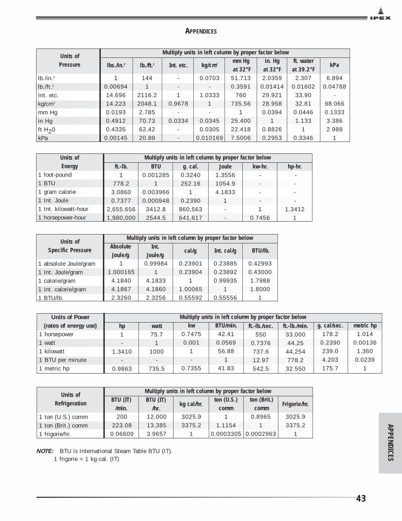
APPENDICES
43
APPENDICES
10.0069414.69614.2230.01930.49120.4335
0.00145
1441
2116.22048.12.78570.7362.4220.89
--1
0.9678-
0.0334--
0.0703-
1.03331-
0.03450.0305
0.010169
mm Hgat 32°F
51.7130.3591
760735.56
125.40022.4187.5006
in. Hgat 32°F2.0359
0.0141429.92128.9580.0394
10.88260.2953
ft. waterat 39.2°F2.307
0.0160233.9032.81
0.04461.133
10.3346
6.8940.04788
-98.0660.13333.3862.988
1
Multiply units in left column by proper factor below
lb./in.2
lb./ft.2
Int. etc.kg/cm2
mm Hgin Hgft H20kPa
kg/cm2Int. etc.lb./ft.2 kPalbs./in.2
Units of Pressure
ft.-lb.1
778.23.08600.7377
2,655,6561,980,000
BTU0.001285
10.0039660.000948
3412.82544.5
g. cal.0.3240252.16
10.2390
860,563641,617
-Joule
1.35561054.94.1833
1--
kw-hr.----1
0.7456
hp-hr.----
1.34121
Multiply units in left column by proper factor belowUnits of Energy
1 foot-pound1 BTU1 gram calorie1 Int. Joule1 Int. kilowatt-hour1 horsepower-hour
hp1-
1.3410-
0.9863
watt75.7
11000
-735.5
kw0.74750.001
1-
0.7355
BTU/min.42.41
0.056956.88
141.83
ft.-lb./sec.550
0.7376737.612.97542.5
ft.-lb./min.33.00044.25
44,254778.2
32.550
g. cal/sec.178.2
0.2390239.04.203175.7
metric hp1.014
0.001361.360
0.02391
Multiply units in left column by proper factor belowUnits of Power (rates of energy use)
1 horsepower1 watt1 kilowatt1 BTU per minute1 metric hp
11.000165
4.18404.18672.3260
0.999841
4.18334.18602.3256
0.239010.23904
11.000650.55592
0.238850.238920.99935
10.55556
0.429930.430001.79881.8000
1
Multiply units in left column by proper factor below
1 absolute Joule/gram1 Int. Joule/gram1 calorie/gram1 int. calorie/gram1 BTU/lb.
Int. cal/g BTU/lb.cal/gInt.
Joule/gAbsoluteJoule/g
Units of Specific Pressure
200223.08
0.06609
12,00013,3853.9657
3025.93375.2
1
11.1154
0.0003305
0.89651
0.0002963
3025.93375.2
1
Multiply units in left column by proper factor below
1 ton (U.S.) comm1 ton (Brit.) comm1 frigorie/hr.
ton (U.S.)comm
ton (Brit.)comm
Frigorie/hr.kg cal/hr.BTU (IT)
/hr.BTU (IT)
/min.
Units of Refrigeration
NOTE: BTU is International Steam Table BTU (IT).1 frigorie = 1 kg cal. (IT)

APPE
NDI
CES
44
°F
-459.4-450-440-430-420-410-400-390-380-370-360-350-340-330-320-310-300-290-280-273-270-260-250-240-230-220-210-200-190-180-170-160-150-140-130-120-110-100
-90-80-70-60-50-40-30-20-10
0
°C
-273-268-262-257-251-246-240-234-229-223-218-212-207-201-196-190-184-179-173-169-168-162-157-151-146-140-134-129-123-118-112-107-101
-96-90-84-79-73-68-62-57-51-46-40-34-29-23-17.8
°F
123456789
101112131415161718192021222324252627282930313233343536373839404142434445464748495051525354555657585960
°C
-17.2-16.7-16.1-15.6-15.0-14.4-13.9-13.3-12.8-12.2-11.7-11.1-10.6-10.0
-9.4-8.9-8.3-7.8-7.2-6.7-6.1-5.6-5.0-4.4-3.9-3.3-2.8-2.2-1.7-1.1-0.60.00.61.11.72.22.83.33.94.45.05.66.16.77.27.88.38.99.4
10.010.611.111.712.212.813.313.914.415.015.6
°F
616263646566676869707172737475767778798081828384858687888990919293949596979899
100110120130140150160170180190200210212220230240250260270280290
°C
16.116.717.217.818.318.919.420.020.621.121.722.222.823.323.924.425.025.626.126.727.227.828.328.929.430.030.631.131.732.232.833.333.934.435.035.636.136.737.237.84349546066717782889299
100104110116121127132138143
°F
300310320330340350360370380390400410420430440450460470480490500510520530540550560570580590600610620630640650660670680690700710720730740750760770780790800810820830840850860870880890
°C
149154160166171177182188193199204210215221227232238243249254260266271277282288293299304310316321327332338343349354360366371377382388393399404410416421427432438443449454460466471477
°F
900910920930940950960970980990
10001020104010601080110011201140116011801200122012401260128013001350140014501500155016001650170017501800185019001950200020502100215022002250230023502400245025002550260026502700275028002850290029503000
°C
482488493499504510516521527532538549560571582593604616627638649660671682693704732760788816843871899927954982
101010381066109311211149117712041232126012881316134313711399142714541482151015381566159316211649
The following formulas may also be used for converting Centigrade or Fahrenheit degrees into the other scales.
Degrees Cent. °C = (°F - 32) Degrees Fahr. °F = °C + 32
Degrees Kelvin °T = °C + 273.2 Degrees Rankine °R = °F + 459.7
TEMPERATURE CONVERSION
59
95
APPENDICES
WARRANTY: All of the Company's Products are guaranteed against defects resulting from faulty workmanship or materials. TheCompany will replace, free of charge, including shipping charges for the replacement Products, any Products which are found to bedefective in workmanship or material, provided that the following conditions are met:
a) the Company is promptly notified in writing of such defect immediately upon discovery of same, and the defectiveProduct is promptly returned to the Company; b) the defect is not due, without limitation, to faulty installation, misalignment of Products, vibration, ordinary wear andtear, corrosion, erosion, U.V. degradation, incompatible lubricants, pastes and thread sealants, unusual pressure surges orpulsation, water hammer, temperature shocking, or fouling; andc) the Products have not been altered or modified after leaving the Company's premises.
The warranty period can be specifically limited for certain Products as stated in writing in the Company's literature.
The Company will not allow claims for labor, materials and/or other expenses required to replace the defective Product, or torepair any damage resulting from the use thereof. The Company disclaims any responsibility for the Purchaser's calculations,product drawings or engineering design specifications. The Company's liability is limited to the purchase price applicable tothe product.
It is agreed and understood that the Company's liability in respect to the sale is strictly limited to the replacement of Productsas hereinbefore specified and that the Company shall not, in any event, be liable for any damages whether for the loss of useor business interruption or any other claim for incidental, consequential, special or punitive damages. There is no warranty,condition or representation of any nature whatsoever, expressed or implied, by statute or otherwise, except as herein contained,and the Company disclaims any implied warranties of merchantability and/or fitness of its Products for a special purpose.
This literature is published in good faith and is believed to be reliable. However, IPEX does not represent and/or warrant inany manner the information and suggestions contained in this brochure. Data presented is the result of laboratory tests andfield experience.
IPEX maintains a policy of ongoing product improvement. This may result in modification of features and/orspecifications without notice.
BRINALIP001050© 2002 IPEX IND0036UC
SALES AND CUSTOMER SERVICE
Canadian Customers call
Toll free: (866) 473-9462
U.S. Customers call
Toll free: (800) 463-9572
www. ipex inc.com
About IPEX
IPEX is a leading supplier of thermoplastic piping systems. We provide our
customers with one of the world’s largest and most comprehensive product
lines. All IPEX products are backed by over 50 years of experience. With
state-of-the-art manufacturing facilities and distribution centers across
North America, the IPEX name is synonymous with quality and
performance.
Our products and systems have been designed for a broad range of
customers and markets. Contact us for information on:
• PVC, CPVC, PP, ABS, PEX and PE pipe and fittings (1/4" to 48")
• Industrial process piping systems
• Double containment systems
• Acid waste systems
• High purity systems
• Municipal pressure and gravity piping systems
• Plumbing and mechanical pipe systems
• PVC electrical systems
• Telecommunications and utility piping systems
• Irrigation systems
• Radiant heating systems
• Cements, primers and accessories