Embed Size (px)
Citation preview

volume U cha ter 3
ENGINE CONSTRUCTION AND RELATED COMPONENTS
Each engine is encased ln Its own nacelle package. The pylon supports the engine and nacelle and provides a means of attaching them to the aircraft structure. Each power package consists of the engine, accessories, cowling, engine mounts, and exhaust duct-thrust reverser assembly.
Within the nacelle are two firewall& of corrosion resistant steel. The vertical firewall d1vldes the nacelle into two zones, No. 1 and 2. Zone ~o. 1 Ls aft of the !lrewall, and Zone No. 2 Is on the forward side. A horizontal firewall separates the pylon structure from the eng:lne.
The nacelle has a zero lnlet duct which means that the duct length Is very short ln front. of the lnlet guide vanes. Spring-loaded blow-in doors in the
VOL. n
HORI ZONTAl. r I R[VA I.I.
OIGINE fiRE'JAUS
VCATIC AL
ri ll[ VALL
3-1

... I
"'
"YL() ..
A(T COWL "AN[L
l
DUCT
rORWARO [NGIH[ NOUIITS
COWL NACELLE CONSTRUCTION
"YLOH I Ok STRUCTUR[
(NC t H ['"NOUN T
£1CN4UST
TNRUST
RlV[RS[It OOOits
NOUL£ ASS[NILY

,
0 PRIMARY & SECON~Y AIR flOW
<D AF"T COWL DUCTS & N2 CQ.IPRESS~
® ArT COWL DUCTS & TURBINE ® fAN & ENGINE EXHAUST NOZZLE
VOL. n 3-3

nose cowl open during starting :md low airspeed to provide sufficient airflow to the fan rotors. When airspeed Increases to a value where ram air supplies airflow needs, differential pressure across the doors drops ancl they are springloaded closed.
Aft of the nose cowl is a bifurcated duct which bolts to the f:ln discharge case. This duct directs the fan airflow (secondary airflow) into two channels on the left and right side::; o[ the engine. The forward cowl doors which enclose the bifurcated duct hinge on the upper left and right sides of the engine and latch on the bottom centerllne. The aft cowl doors are hinged and lntched in a like . manner and provide an Integral duct which guides fan discharge air to the exhaust nozzle assembly.
The exhaust nozzle assembly combines the fan and engine exhaust nozzles and the thrust reverser nssernbly. These nozzles direct fan and engine exhaust gases a[t and overboard. The fan exhaust nozzle encloses the engine exhaust nozzle.
Nl COMPRESSOR SECTION (FAN):
Since the fan and Nl compressor are on a common shaft they are discussed under this section along with their related components.
The auxiliary accessory support section Is a one -piece ;·.1agnesium casting. It supports the auxiliary accessory drive and bolts Into the No. 1 bearing support. The auxiliary accessory support provides two mount pads on the forward face, but only one Is usea. It drives the Nl compressor tachometer generator. The lower face of the support section provides a mount for the No. 1 bearing oil scavenge pump.
The aux.lllary accessory drive gear is externally splined and Installed with an "0" ring into the front compressor hub. The hub has an Internal spl!ne which mates with the accessory d1·ive gear. The accessory drive gear powers the N1 tachometer generator and the No. 1 bearing oil scavenge pump.
The compressor air Inlet duct, A-B, bolts to the front compressor [ront airflow duct (front fan case), B-:a. The outer case wall is titanium. Fitted into the inner diameter of the outer case are 23 hollow titanium guide vanes and their spacers. These guide vanes are bolted to the case wall on the outer diameter and riveted to the No. 1 bearing support on the inner diameter. These hollow vanes have an internal webb bracing and a sponge nylon filler which absorbs vibrations. All the vanes carry anti-icing air. In addition, some struts have special functions:
3-4
1 0' clock strut - Air Sens lng 4 O'clock Strut - Oil Pressure 8 O'clock strut - Scavenge OU
9 O'clock Strut - Nl TACH Gen Wire 11 O'clock strut - Breather
VOL. II

'"' I <n
2 2 5 ---- - - - -- 3 -- - ---- - 4 - - ST AT I OH -- - -- - - - - - - 5 - - - - - 1 14 7----::---=~ 27.8-------- 77. 1 ---- - --235 - Pr PSI A ---- -- - -- --221 - - - - 28 . 1 ~ ---- - -1~ ----- - 4f --- ---7f -- TT Of---- - - ---- --1~ -- - - lt9
T i _a T -~ -~ l' ! ~ i -' '""" ~ ' f ~ -~ lfl f iiOHT
CO"'PRtSS OR fRONT CASE
(3 )
•
I ~ - ~ ~-.
I HTERM £D I AT £
CAS[
DiffUSER
CASE •
lk~---~~-'-HAIH ~ / ~
A C C [ SSORY --..... .u.+-I """~.,..--.JI7..r ...... CAS £
~,..JU,~--~---~,-~-~ ;r~o f RONT COMPRESSOR REAR CAS£
L_fAH EXHAUST DUCT
\ '- fRONT COMPRESSOR EXI T ST RUT CASt
fRONT COMPRESSOR REAR A IR f lOW DU CT
l_ f RONT COMPRESSOR fRONT A IR fl OW DUCT
L- COHPIItSSOII A I R INl ET CAS E
TUR B INE EXHAUS T CAS£
TURI IN£ HOlll t CASt
RE Ali OUTER COMBUSTION CHAMBER CAS £
fRONT OUTE R COMBUS T ION CH AMB ER CASt
'-- AUX ACC ESSORY DRI VE PAD ENG INE CASES, FLANGES, AND STATIONS

No. 1 BEAR I NG
RETA I N I NG NUT
(INNER RACt)
1 eu~ ' "'"
AUXIL I ARY _.J.~--- ~~ FRONT COMPRESSOR HUA
A~CtSSORY CR IV£
No.1 I> tAR INC
RETA I NING HUT
(OUTER RA CE )
3-6
NO.1 BEARING AND SEAL
S£A l.
A I ~ CON T ~OL S(A l
VOL. U

VOL. fi
S~ONGt
NY~ON
01~ ~ASSAGE
(TYPICAl OF' 4 &. 8 o'c~OCK STRUTS)
CONOUIT F'OR - ---O IL, AI. , o• ~ 1 -[S
AIR INLET CASE - INLET GU IDE VANE INSTALLATION
3-7
c.> I
00
COMPRESSOR ~IR
IN~
No. I IIRCi SU~~ORT
ACC US HS G MOUNT rLAHG[
(fwO)
RUAINU~
CON[ (BULLET )
Suft.-011 T
VRAT HOtll[
VAN£ ( HOT SHOWN 8[LOW) ANCHOR R INC~ ft ./fRONT COMPRESSOR fRONT
BOl lS ~.. A l A r LOW CAS(
111 ~AIR (N OT SHOWN BE LOW) \w~-c~~ ---------fRONT COMPRESSOR
fROHT A I R fLOW DUCT AIR TRAN S fER TU8[
liT STAal ltltlfll DUCT
AN D RINC
'I If FLAHG( A
COMPRESSOR AIR INL£T CASE
SuPPORT
PRESSURE

< 0 r
VAN(
COMPRESSOR INLET
= NOl SHO~~ 8£LOW (sr£ r1c 6 &. 7)
'f fLANGE "811
"'
lRANSr[R RIHG AHO fU8(
STATOR POSITION PLAT£ ( rROHl)
o'
STATOR VAN£
FRONT COMPRESSOR - FRONT &. REAR AIR FLOW DUCTS AND fiRST STATOR
NOT SHO"H 8£L0"
FAN OUCT 2HO STAG [
It " ,.LANGE C
STATOR YAM(
over
fAN SPAC£R

w I .....
0
rRONT COMPRESSOR
REAR AIR fLOW DUCT
STATOR VANE (NOT SHOWN)
fAN DUCT 2ND STAG£
I
I
I
I I I
I
"c"
v SPOil(R
"o" "
rRONT COMPRESSOR CAS£ (OUTER)
(NOT SHOWN)
INN[R CAS(
COMP ROTOR
STATOR 2ND STAGE
'-----FLANGE "c" --------~~~~~ f""L ANC£ "0 ''
FlANGE 110 11
FRONT COMPRESSOR REAR AIR FLOW DUCT EXIT STRUT CASE

These special functions are discussed In later chapters under related subsystems.
The purpose of the Inlet guide vanes ls two-fold: First, they direct Incoming air onto the rotors at the best angle for compression. Second, they distribute the No. 1 bearing support load to the outer case. On the loner diameter of the vanes, the fore und aft No. 1 bearing support shells are riveted. These components form the No. l bearing scavenge sump.
The front compressor front airflow duct (front fan case) B-B, bolts to the rear of the air inlet duct and to the front flange (Bl) of the front compressor rear airflow duct (rear fan case). The front airflow duct (front fan case) ls aluminum and fits over the first-s~ge·fan duct. Tbe first-stage rotor of the Nl compressor rotates inside this fan duct. Riveted to the flrst-5tage fan duct and to front and rear stator position plates are 48 aluminum alloy stator blades. These blades help provide compression and serve to guide fan airflow onto the second-stage rotor. At the Inside diameter of the stator blades Is a spoiler, which rides on the knile edge of the rotating fan spacer. The purpose of this spoiler is to prevent air leakage around the Inner diameter of the stators. Should leakage occur, engine efficiency would decrease. The stator blades are replaceable. For easy maintenance, they slip Into the rear airflow duct (rear fan case).
The front compressor rear airflow duct (rear fan case) shown as B-C ln the Illustration is aluminum and houses the first-stage (fan) stator assembly as noted above. The·second-stage fan duct slips into the rear airflow duct and bolts to an Internal flange. This duct houses the second-stage rotor. During disassembly, this fan duct must be removed from the forward end.
The rear fan duct slips Into the rear airflow duct at flange C. The leading edge lip fits over the aft lip of the second-stage fan duct making a streamlined passage to the front compressor eldt case and the Nl Inner case Inlet. The rear fan duct bolts Into position with the front compressor exit case at flange C.
In summary, the front compressor front case (fan case) Is divided Into two parts: the front (fan) and rear (fan) airflow ducts, which house the first two stages of the low pressure (Nl) compressor. These first two stages, then, are the fan.
The front compressor eldt strut case (fa:n discharge case) shown as C-D, divides fan airflow Into two paths: primary and secondary. The secondary alr flows into the blfurcated duct, as shown earlier In this chapter; primary air flows into the Nl compressor via second- stage stator vanes.
The exit case is stainless steel and supports 38 steel eldt guide vanes on Its outer circumference. The inner circumference houses the second and thlrd
VOL. II 3-ll

stator assemblies and the third-stage rotor.
The second-stage stator Is bolted to the forw:1rd Inside diameter of the exit case and extends forward Into the rear airflow duct. The 48 aluminum alloy vanes are Individually replaceable and form a continuous ring. At their Inside diameter they are riveted to a shroud which forms an air seal on the inner end o{ the vanes. The second-stage stators are pinned to the third stage for alignment and to prevent the stator sections from rotating within the case.
The third-stage stators are a two-piece assemblies which pin to the secondstage stator on the forward end and to the fourth-stage stator on the aft end. The 56 vanes are made of aluminum alloy and riveted to a spoUer shroud on the inner diameter. This spoUer serves as an air seal to prevent air leakage on the Inner end of the stators. Tl!e outer circumference of the third stage rivets to an inner compressor ducr on the forward end. The inner duct and the spoiler shrouds are two-piece units to allow ease of maintenance. The stator vanes are replaceable.
Nl COMPRESSOR SECTION (COMPRESSOR).
The front compressor rear case (Nl compressor case), D-F In the Illustration, Is a one-piece aluminum structure. It bolts to the front compressor exit strut case (fan discharge case) at flange D and to the Intermediate case at flange F. There Is a dummy flange, £, at mid-case. The front compressor rear case (Nl compressor case) houses the remaining five stages of the compressor. Each stator stage Is constr1,1cted In halves.
The 66 fourth-stage vanes are made of replacable aluminum alloy. The outer circumference Is riveted to the compressor Inner duct on th.e forward end. The inner circumference is riveted to an air seal spoUer shroud. The compressor inner duct serves as a spacer between stator sections and Is pinned for alignment and to prevent rotation within the case.
The fifth-stage stator Is a two-piece steel assembly. The 96 stator vanes are all welded on the Inner diameter. Every sixth vane on the outer diameter Is welded. This provides flexibility and room for expansion without putting undue strain on the case. The fifth-stage Is not attached to a compressor Inner duct but assemblies between the fourth and sixth stage ducts which act as spacer and pin to the fifth stage.
The sl.xth through eight stages are of two-piece steel construction. The vanes, of which the sixth stage has 96 blades, the seventh stage, 106 blades, and the eighth stage, 120 blades, are welded on the Inner diameter and strap welded on the outer diameter. In additloo, the vane segments are assembled with and pinned to Inner ducts which act as spacers. Each stage ls pinned to the one In
3-12 VOL. II

rRONl COMPRESSOR R(AR CASE
(INNER oucr )
3
Ali GNH(Hl ANO ~ AH T' • AOT A l I ON
oowns
(TYPICAL2 , ,'
4
/ fRONl COMPRESSOR R(AR CASE
(ouTeR)
5 6 7
t A LUM I
8
Nl COMPRESSOR STATORS AND CASE
r
S1A10R 5PLIC(
\PLATES
-..,

front and the one aft. The vanes r ve an aluminum spoiler shroud riveted on their inner diameter. These spot. rs form an air seal on the Inner end of the stators. Stator splice plates, which fasten the two-piece sections together, are staggered 90 degrees during installation.
The front compressor rear case (Nl outer case) is installed from the rear. It tapers from flange D to flange F to conform to decreasing blade size and compressor volume.
Nl COMPRESSOR SECTION @OTOR ASSEMBLY).
The Nl cam pressor rotor assembly consists of nine stages. The front compressor disk and hub are an Integral unit supported by the No. 1 bearing. The hub is internally spllned and drives the front accessories. The disk mounts the firststage fan blades. Sixteen tie rods, which secure the ian rotor stack, are Inserted from the front disk and thread into the second spacer. A nut on the front disk provides torque on the stack. The _front and aft disks are separated by a spacer which has two knife-edge air seals used with the stator shrouds. The aft disk mounts the second-stage fan blades. Snap flanges on the front and rear face receive the spacers. The second spacer separates the second-stage fan rotor and the third stage of the compressor.
There are 34 first-stage fan blades. These blades are of steel and have a stellite mid-span shroud. This shroud locks the blades together during operation which helps to .strengthen the blades.
The 30 second-stage blades are also made of steel but are pin-mounted to the disk. This allows the blades to move 1 1/2 Inches radially and 1/4 inch longitudinally at the blade tip. This movement allows the blades to take their best operating position and helps compensate for uneven loading.
The rotor disks In the third through ninth stages are of varying weights and thiclmesses to compensate for vibration levels experienced with this engine. Each segment Is designed for maximum strength at maximum operation. On the front and rear of each disk are snap flanges. The third stage forward side mates with the No. 2 fan spacer. The third stage aft side, the fore and aft sides of the fourth through eighth, and the forward side of the ninth disks accept the disk spacers. At the seventh disk aft side, just in front of the spacer, Is the front compressor rotor rear hub.
A1r seals are formed by the stator vane Inner shrouds and the knife-edge seals on disk spacers. The spacers fit into the snap flanges of the disks separating the disks and helping to transmit torque from rotor segment to rotor segment.
The rear hub Is assembled into the disk-spacer stack at the seventh disk to
3-14 VOL. ll

c.; I ,_. .. ,
< 0 r t:l
BAL WTS (STATIC)
YAM Tl[·llODS (16)
\._ COH ~ T1 [ · ll OOS ( 16)
Nl CG1PRESSOR ROTOR
\ • \~~
~- ·1 I
I
/
KNIH •EOC:[ SULS ( ~~ (TYPIC AL) ~
rRONT COMPRtSSOA RtAII ROTOR HUB

w I ... "'
rRONT COM~N(SSON O~IV( TUROIN( 'HArT
COUPl1 N8
No.3 &t•,. oN;.
S( Al ( AIItlllt i(R
No.3 et•" •" <.
No. 2-1/2 ~c•R oH<. No. l at• A,,.'" Ouf'l( .( 8 ALL
fH $1AQl
.........
l tH • Rik·.-. -, (Al
c c • ~BcN r • cf r~~f C)Pfhl '-/Ill 1
I
SPA AY NOllL(
r t8 (111 (.L A SS
H (A f S H I ( l0
12t H
NUT
/
'\ AS f (HAh(('' flll(R
Oil PRtSSURt (6 O'CLOCK
No. 2, 2 1/2, AND 3 BEARINGS AND SEALS
~fii'LI N ( TO .. H2 ( H4PA: ( SSOA SHAf'
No.3 et• oo HG ~ t• L (C AA:8VN f A (( TY~l,
IHTtRM£0 CASe)

w I
SW((NY WH[N~H SPLINt
NUT RtTA INER
~~ (OMP R(AH HU8
Nl TURBIN( St-U ,l
( \
Nl fUkUIN( . t"' A fl~oj
r - LOCr -, ~
om• ~~r IIV1
Ill TU~OIN( ~uT AND RETAINER
Nl TUROIN( SHAfT IIUT AND RETAINER

to lessen the effect of vibrations and to keep the total engine length to a mlnl.mum. The rear hub Is supported by the No. 2, 2 1/ 2, and 3 bearings and mounts the related bearing seals and seal supports. In addition, the rear hub splines over the N1 turbine shaft. The N1 compressor shaft is bolted to the Nl turbine shaft with an internal nut and spacer and is prevented from loosening by a springloaded lock. Holes In the hub flange allow ninth-stage bleed air Into the rotor. This air provides turbine coollng and No. 1 and 2 bearing alr load for the carbon seals.
Sixteen tie rods, installed In the second ian spacer, secure the rotor stack from third and ninth stage and join the fan to the compressor section. These tie rods are removed from the forward side which allows the fan to be removed and replaced without disassembling the compressor.
The compressor blades~ thiTd to ninth stage, are steel. Blade numbers by stage follow:
o Third stage - 36 blades o Fourth stage - 51 blades o Fifth stage - 62 blades o Sixth stage - 62 blades o Seventh stage - 82 blades o Eighth stage - 100 blades o Ninth stage - 102 blades
These blades are dovetailed to their disks and are retained by expandable tab locks. The blades· have what are called "squealer" tips. These special tips provide a turbulence which minimizes air leakage on the outer end of the rotors.
N2 COMPRESSOR SECTION (INTERMEDIATE CASE).
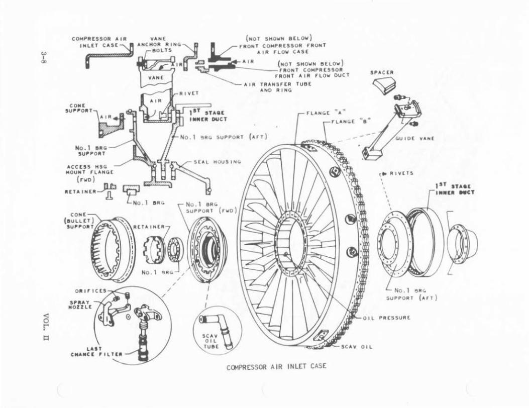
The intermediate case, bolts to the front compressor rear case (Nl compressor outer case) at flange F and to the diffuser case at flange G. The intermediate case forms the N2 compressor outer case. The N2 outer case has two acceleration bleed valves at the twelfth stage: one of 4 3/4-inch diameter on the left side, one of 6-lnch diameter on the right side.
On the forward flange (F) there are eight mO\mting lugs. The four top lugs are used to mount the engine to the pylon (forward engine mount), the bottom four forward lugs are used with the engine stand for removal and installation.
The ninth-stage stator for the N1 compressor Is formed by the forward part of the Intermediate case. The outer circumference of the case forms a bearing vent manifold. A vent adapter tube 1n the 6 o'clock strut connects the bearing cavity and the vent annulus.
3-18 VOL. ll

~ I ... "'
LUBRIC ATION ORiriCCS -~------,
''LAST CHANCE'' f tLTlA
No.2 BEARING SUPPORT
Oll TRAH Sf(A TU6(
( NCIN( fi40UN1
V(.., T A"'NUl.US
SUPPORT
CARBON SEAL OIL TA~N$f(R TUB[
HEAT 5 HI(L0 A 55(N8~Y
SEAL SUPPORT
~AlA SEAL RING
( l.0W[ It H Al l f)f ( A~()
LUBRIC ATI ON LIN£
(CI<L ARG£0)
''LAST CH ANt£ fllrCR
L H ( A T S H I(LO A S5 (M8 l '1'
rt 8£A GL ASS &LAHK(TS
A IR S( AI.. RI NG
(To N2 ROTOR)
INTERMED IATE CASE INNER STRUCTURE
... I
"" 0
< 0 r 1=1
I I
L--...;..- 4 3/4. I ~~~,,o
I r olll
I
,---_; I I I I I I I L--
9
t vtlll
"'"
\2lM sto\Gt ·~ttO pOfll
. sto\Gt
ll~(lO MO~U.
IIL(tO HO~tS 112 Ct).IPR£SS00 CAS£ AND STATORS
tMltll .. to•"'t Co\St
"""' (stud Slllo\P wt~OtO
co .. r•ts•Dfl Co\St
sro•~'" (,. ~...,. . .. ~~o~)

ANNULUS
SCAVENGE
' 8:30 STRUT SCAVENGE O IL #1 BEARING TO GEAR BOX
SPIDER
CARBON SEAL SUPPORT
A spider on the bottom of the 6 o'clock strut combines the fittings for the vent adapter, pressure line from the pump,. and the scavenge line from the accessory case.
The No. 2 bearing seal support Is welded into the inner periphery of the lntermediate case. The No. 2 bearing seal housing bolts to the forward face of the seal support and supports the forward heat shield. The No. 2 bearing housing bolts between the nlnth-stage stator and the aft face of the bearing support. The No. 3 bearing seal support and seal housing bolts to the No. 2 bearing housing. In addition, the No. 3 seal support bolts to the inner stator flange. The seal housing supports a fiberglas heat shield assembly.
Assembled with the No. 3 seal support Is an air seal ring. This ring contacts the N2 rotor and prevents air leakage across the front of the N2 compressor.
The rear compressor case (inner) Is of one-piece steel construction. It slips into the intermediate case on the forward end and Is flanged and bolted at the diffuser end (flange F). The N2 stator vane assemblies nest inside this case. The twelfth-stage bleed holes circle the case just over the twelfth-stage rotor stage. These bleed holes port twelfth- stage air between the inner and outer cases.
The six stator assemblies are of steel, continuous-ring construction. The stator blades are all welded on the inner diameter. The outer diameter Is strap welded. At the Inner diameter an aluminum alloy spoiler shroud Is riveted to prevent air leakage. Assembled with the stator sections Is an integTal duct which serves as a spacer between segments. The stator segments nest into the inner case. The tenth stage butts against a flange; the fifteenth stage Is secured by four screws.
VOL. ll 3-21

Each stage Is pinned to the others for alignment and to prevent rotation in the case. Following Is a list, by stage, of blade numbers.
Tenth stage - 96 blades Eleventh stage - 122 blades Twelfth stage - 128 blades Thirteenth stage - 140 blades Fourteenth stage - 150 blades Fifteenth stage - 174 blades
N2 COMPRESSOR SECTION (ROTOR),
The N2 compressor rotor Is a seven-stage steel alloy assembly. The rotor disks are machined In asaort'ed sizes and thicknesses depending on their strength requirements. Each disk Is made with snap flanges on the front and rear sides. The tenth-stage disk has an air seal mounted Into the front snap flange. The eleventh through sixteenth stage flanges mate with spacers. In addition, the twelfth stage accepts the N2 rotor front hub; the sixteenth stage accepts the rear hub.
The six spacers are separate steel disks with machined knife- edge seals on their rims. They separate the rotor segments and shrink fit Into the rotor snap flanges. When assembled into the rotor stack the spacers help transmit torque. The knife-edge seals mate with the stator spoiler shrouds and form air seals.
The front hub assembly mounts Into the forward flange of the twelfth-stage rotor which reduces overall engine length and the effects of vibrations. The N2 front hub Is supported by the No. 3 bearing, and also drives the No. 3 seal carrier. The alr seal tube which Is shrunk fit Into the front hub prevents N2 rotor air from leaking down the shaft. The front hub flange has ex.lt boles which .allow twelfth-stage air to exhaust forward, creating approximately 4, 000 pounds thrust to offset the engine thrust load on the No. 4 bearing.
The rear hub Is flanged to the aft side of the sixteenth-stage rotor. Just above the hub flange Is an air seal contact flange which mates with N2 rotor air seals. The rear hub Is Installed over the air seal tube with piston ring type seals. The rear hub also mounts the No. -1 bearing, No. 4 seal plate, and the accessory drive gear. The aft end of the N2 hub splines Into the N2 turbine shaft with a spacer. Left and right-hand threaded nuts secure the assembly.
The 16 N2 compressor tie rods are Installed from the rear (sixteenth- stage rotor) thus securing the rotor stack. The forged steel compressor blades dovetail Into the rotors. The blades are secured by expandable tab locks. In addition, the blades are "squeeler" tipped.
3-22 VOL. ll

.., I
N ..,
•oroa A 1• SlAL~
(~•o•n )
I A L It T(l!l (OYNANI C)
IAL ItT ( DYMANI C)
" I
A I._ Sl.A. L
~IMQ
TAll LOC K
14 A IR SCAL
BAL "' (sutoc) 2 l"RU 6 DISCS
; CONT ACT fl.ANC.(
(R (AR)
'
~ l tlON .INCi
S U LS
... IIA L "' (DYNAM O C)
Tl( ~ODS
( 16)
•i>~ N2 CG1PRESSOO ROTOR

< 0 r
16TM r 18ERGLASS HEAT SHIELDS
AIR
N2 COMPRESSOR REAR HU8
Nl
•••• IIAL AIIIMeLY
9TH STAG[ AIR::>
CAR BON S[AL NO 4 8[ARING
OIL PRESSUR[ (4 O'CLOCK, DlrrUS[R STRUT)----~
NUMBER 4 BEARING AND SEAL
OlrruS£R CAS£ INN[R STRUCTuRE
ACC[SSORY ORIV( G[AR
11LAST CHAHC£
11 FI LT ER

N2 COMPR ESSOR ArT Hu e
DIFFUSER SECTION.
The diffuser case bolts to the Intermediate case at flange G and to the combustion case at flange H. The outer weldment forms a plenum which bleeds off high velocity "outside diameter" air. Outside diameter air Is differentiated from Inside diameter air by the position from which It is bled off and by its relative cleanliness. Outside diameter air has high velocity and would tend to keep heavy particles suspended in lt. Inside diameter air is of lower velocity and higher static pressure. Large particles separate leaving cleaner air. Outside diameter bleed ports are round with three bolt holes; Inside diameter ports are oval with multiple bolt holes.
The outer weldment provides Internal mounts for the fuel manifold and burner cans and external mounts for the accessory case, igniter plugs, and the pressurizing and dump valve.
Eight hollow struts join the Inner and outer weldments. The twelve o'clock strut vents the No. 4, 4 1/ 2, and 5 bearing cavities. It also supplies Inside diameter air to the acceleration bleed control. The No. 1, 3, 9, and 10 o'clock struts extract Inside diameter air for environmental systems. The 4 o'clock strut supplies pressure oil to the No. 4 and 5 hearings. The 6 o'clock strut houses the tower shaft housing for the accessory drive. The 8 o'clock strut scavenges oil from the No. 4 and 5 bearing.
The Inner weldment bolts to the Inner combustion case and heat shield on the aft end. On the forward end It forms a two walled duct supporting the sixteenthstage stator vanes of which there are .1.30. The No. 4 bearing housing bolts to the forward face Inner diameter. This housing supports a seal assembly and head
VOL. II 3- 25

H
OUTER WELOM[NT
.t.IR &L££0
BRG CAVllY Y
IHN[R WELOM[NT
...
S TA TOll SHIIOUO OIHUSER C.t.S[
DIFFUSER A.SS046LY

shield. A bracket on the aft Inner diameter helps support the fuel mantiold.
COMBUSTION SECTION.
The combustion section outer casing Is a two piece steel construction. It Is formed Into two cases (H-J forward, J-K aft) for easy access to the burner cans. The outer casing retains the air around the burners. In the bottom of the aft portion of the casing Is 11 reed type drain valve. This valve opens at 2 to 4 pounds per square Inch to drain the residual fuel from the combustion section any time raw fuel has collected in this area.
Housed in the case are eight nickel alloy steel combustion liners (burner. cans). The burners are made of a series of rings, roll-welded together. The air distribution tube In the center of the burner eflectlvely Increases burner area. It too Is made of ringed sections roll-welded together. Both the can and the tube are welded in such a manner as to leave spaces between the welds. These spaces form cooling tabs allowing air to flow along the Inside surfaces of the can, thus providing a cooling blanket of air to Insulate the sides of the burner. Additional holes are in the burner cans for mixing the fuel-air mixture and for flame dilution.
Cross-over tubes connect the burner cans. These tubes connect the burner cans in a male-female CollDectlon and spread the flame from one can to the other.
The burner cans are attached to a bracket on the front end. This bracket Is bolted between flange G and Hand accepts a hook on the burner. The fuel nozzles also pr ovide support on the forward end of the burner cans. At the rear end, the bu.rner cans clamp Into a transition duct. The transition duct bolts to the turbine case at flange K to secure the burners and direct combustion gases onto the turbine.
VOL. n 3-27

w I
"" <X>
a r --
B A~~~===========~~ I.J:=:?'" \ OU T(R C0 .. 8US T ION _j i H CASt (AfT) K
OU T<R COMBUS TI ON
CASt (rwo)
I HH(R COMBUS T ION CAS[
OUT(A COMBUSTION
C ASt ( rwo) l
IHN(R CON8USTION
CAS t HE AT SHI ( LO !'
I I
r lll(R~LASS !hAHK( J
I I
8Rt.
HOUSIN(.
OIL O R triCES
L OIL P RE SS. ttl
. (-~ '.~ Lt Nl -& ..,.. ~
L __ t1t ~~ ; . SC AV [NC.t IU8 t . ·.
H
INNER AND OUTER COOUST ION CASE ASSO.BLY
r t&CRGL A$5
fi HH(O
l • ~ '-'·~·· · J
Ht.(O ._. 4 LY( -
OUT[R COHB USTION f "" )m)
I NH[R
CON8U S T tON ( A S(

"" I
"' "'
rutL NOZZL £5 ------11
rutL
rLAMt TUIIt
/
CAN ANNULAR C().18UST ION CHAMBER

..., I ...,
0
fllANS IT I ON OUC T ASSY
8UAH(A CLAMP
T /cOMBUS T ION
OUT LlT
N2 IUA6 uUIO( VAtr.I(S
COMB USTION CHAM8[A
jOUTl[T DUCT POSITIOH I
Pl • TE
S U~POAT
TUII. I N(
~~~;_--------:;~~~~~~~~~~::~~ (XNAUST c••t
4 TH STAQ( TUII81N[ IIOTOII S (A L
2 3 4
TURBINE NOZZLE CASE
A~R CONTROl. 1
SEALS S POil(AS
Nl TuAC CUIO[ YAN(
( ~
I
A three-walled combustion Inner case houses and protects the turbine shafts. It also encloses the pressure and scavenge oil tubes for the No. 3 bearing. A dual scavenge pump is also housed in the Inner case. In addition to the above, the Inner case forms a \'ent cavity and scavenge sump for tbe No. -1, l 1/2, and 5 be:1rlngs.
TURBINE SECTION.
The turbine nozzle case, K-L, is a one-piece steel structure. Il encloses the N1 and N2 of the turbines. Each stage consists of a stator assembly located In front of a rotor assembly.
A stator assembly consists basically of a row of Individually replaceable stator vanes and an air control ring. The vanes are shrouded at their Ups and are classified by size. The vanes determine nozzle area and angle of gas flow to the turbine wheel aft of each row of stators. During assembly, the class of the vanes Is varied to obtain the specliled nozzle area. When replacing vanes, use the sanae class to prevent changing the nozzle area.
The flrst·stage stator vanes are Installed from the front. They are slipped in and pinned at the outSide diameter to a flange on the Inside oi the turbine nozzle case. The Inside diameter blades fit over lugs on a flange of the turbine stator support case. They are safetled by a special heat resistent safety wire run through the lugs.
The second, third, and fourth stages are installed from the rear and are positioned by spacers at their outer ends. The Inner ends have lug tips which fit into channels In the air control rings. The fourth-stage turbine rotor outer seal fits In behind the fourth-stage stator vanes and retains the second, third, and fourth stages and their spacers.
The air control rings control airflow at the stator vanes' inner ends. The No. 1 ring fits between the N1 and N2 turbines or the first and second-stage turbine wheels. It has knife edges, which are opposite flanges on the rear face of the No. 1 turbine wheel and the front face of the No. 2 turbine wheel, form lng an air seal. The No. 2 ring fits between the No. 2 and No. 3 turbine wheels. It uses a fiat spoiler opposite knife edges on the turbine rotor spacer to form an air seal. The No. 3 rlng ts between the No. 3 and No. 4 turbine wheels. It has the same type of seal as the l';o, 2 ring.
The stator spacers Interlock with the outer tips of the stator vanes. They are also used as an atr seal. The No. 1 spacer has knlie edges opposite the No. 1 turbine's blade tip shroud. The No. 2 and No. 3 spacers do not have knife edges; they are stepped for a spoiler effect. The knife edges are on the blade tip shrouds of the No. 2 and No. 3 turbine wheels. The No. 4 turbine blade tip shroud has
VOL, D 3-31

N2 NOlZLl GUIOl VANU
(cLASS! r llO)
N2 TURBINE INSPECT ION

the knife edges oppostte the stepped fourth-stage rotor seal. These seals contain the diverging gas flow minimizing the leakage around the outside of the blade tip shrouds.
A combustion chamber outlet duct is positioned by a plate to the rear flange on the inner combustion case. The plate has an Inner bolt ring and eight tabs which e>.."tend around the outer edge. Locating pins e>..'tend rearward from four of these tabs. It Is on these locating pins the outlet duct Is correctly positioned.
The center opening of the outlet duct Is larger In diameter than the forward flange on the stator support case. The forward flange extends through the opening and mates t the bolt ring on the outlet duct positioning plate. The No. 5 bearing support mates to the rear face of the front flange on the stator support case. From the rear, bolts are Inserted In every other hole around the bearing support. Then from the other side, i.e. the positioning plate side, bolts are placed !.n the remaining holes. In this manner the positlon!.ng plate, combustion case rear flange, stator support case front flange, and the No. 5 bearing support are all joined together.
The turbine stator support or inner turbine case provides a mounting means for the N2 stators and two air control seals. It is cone shaped and, as previously mentioned, bolts to the rear of the Inner combustion case. The two air control seals have knife .edges extending Inward towards opposite flanges on the front face of the N2 turbine wheel. Mounting for the stators is provided by a row of lugs and a stepped flange. The stepped flange and a similar one on the inner rear flange of tlie N2 stator vanes provide a seat for the vanes. Au eye In the stator inner front flange passes over the lug. After the row has been installed the safety wire is used for retaining the vanes.
The No. 5 t-earing support Is internally spl!ned. The spl!nes mesh with similar splines on the periphery of cne No. 5 bearing housing. This radially positions the housing and allows for growth lengthwise due to thermal expansion. The bearing housing Is also fastened to the Inner combustion case heat shidd by the same bolts that hold the bearing seal support and the beat shield to the rear of the bearing support housing.
TURBINE ASSEMBLY (ROTATING).
The rotating turbine assembly is made up of the Nl and N2 turbines. The turbines consists a total of four turbine wheels or disks, two concentric turbine shafts, turbine blades, and tie rods.
The N2 turbine is a single stage turbine that supplles the power to turn the N2 compressor. Physically, It Is the first turbine wheel aft of the combustion section. The turbine wheel is a machined steel disk with provisions for attaching
VOL. n 3-33

No.6 stARING ~
'
COAS S(Al
.;,. J'· r co -..PR£3 "!t)k --·-·-·"'-:· C.r~ IV( TUIItB l l' i
,tlTO.- n (AA f'lJil
No.6 a t~RING stAL
NUMBER 6 BEAR~NG SEALS AND OIL SUMP
OIL I'R(SSUR(
( 3 0 1 CLOCK, UMAUST CASt )
FINAL S CRCCN r I LT tR
SCAV(HG[ OIL AND AI~
(1 O'CLOCK,
UMAUST c.ost )

the turbine blades to Its outer circumference.
The blades :Ire classified by weight In pairs and then lnst:tlled diametrlc:tlly opposite each other. They are fir-treed to the wheel. The broached openings In the wheel are not perpendicular to the frtce of the disk but :~re at about a 10-degree angle to the wheel. They are offset as a method of manufactcrln;r :md assembly that reduces the width of the base of the blade allowing more blades to be Installed around the turbine wheel. On their outer tips, the turbine blades are shrouded to cut down airflow losses. The shrouds are Interlocked In a "Z" shaped joint for added strength.
On the rear face of the ~o. 1 trublne wheel, one seal flange is opposite the knife-edge fastened to the bottom of the No. 2 stator air control rmg.
The front face of the 1':2 turbine is cooled by six-teenth-stage air Uwt has passed aft between the inner combustion case and the case liner. The <.'oollng air can pass outward along the face of the wheels tl:rough the knife seals and finally mix with tbe gas flow just forward of the N2 turbine blades. Part of the cooling air can pass down througb holes In tbe mounting flange to the area betwt:~n the :-12 and Nl shafts. From here It flows forward through the shaft bearings and seals or rearward under the N2 wheel and up its rear face and the front ra .. e <>f the l'io. 2 turbine wheel to mLx with the exhaust flow.
The Inner diameter of the N2 turbine wheel has a soap flange on the forwnrd face for mounttng to the N2 turbine shaft flange. The N2 turbine shaft extends forward through the combustion section coupling the N2 turbine to the :-<2 compressor. At its aft end, just forward of the turbine section, It Is supported by the No. 5 bearing. At the forward end, just aft of the diffuser, It Is spllned to and supported by the N2 compressor rear hub. At the mldpolnt it Is supported by the No. 4 1/2 bearing.
The N2 turbine shaft coupling consists of a spacer, attach nut, and lock nut. The N2 carnpressor rear hub has external splines and the N2 turbine shaft has Internal splines. The spacer flts between the end of the rea.r hub and an Internal shoulder Inside the turbine shaft when the two are spllned together. On the rear face of the same shoulder, an attach nut mates when It Is threaded Into the Internal threads of the rear hub. Once the attach nut is seated, a Jock nut threads Into the Inside of the turbine shaft and seats against the attach nut. The two nuts have opposite threads, e. g. the attach nut Is right hand and the Jock nut is left hand, to provide a locking system for the :\2 compressor and turbine shaft. The nuts themselves have internal splines to match those on the tool used to remove them. They are accessible from the rear end or the turbine after the Nl turbine shaft has been removed.
Just forward of the No. 4 1/2 bearing, the N2 shaft has a series of small holes
VOL. ll 3-35

to allow oil to be scavenged by centrifugal force into the void between the N2 shaft and the combustion case heat shield and illto the No. -t bearing sump.
The Nl turbine ls a three-stage assembly conslstillg of the No. 2 , No. 3, and No. 4 turbine wheels, their seals, a spacer, and ten tie rods.
A turbille rotor seal is between the No. 2 and No. 3 turbine wheels and another between the No. 3 and No. 4 wheels. The spacer is concentrically mounted Inside the rotor seal between the No. 3 and No. 4 wheels. It determilles the stacked dlmenslon after assembly and is available in many different thicknesses for this reason.
Ten tie rods hold the Nl tutb!ne assembly together. The No. 2 wheel bolts to a flange on the rear of the N1 turbine shaft. On the rear of the No. 2 wheel, there Is an integral turbine shaft ex1;ension flange that Is sometimes called the "flower pot." The rest of the turbine assembly, consisting of turbine rotor seal, the No. 3 turbine wheel, another roto.r seal and the spacer, and the ~o. 4 turbine wheel and a flange, Is fastened to the flower pot by the ten tie rods. Special nuts lock Into the flower pot and then the tie rods thread Into the nuts frma the rear of the turbine. Then, on the rear end of the tie rods, the assembly Is secured by nuts and tab locks. The turbine wheels have close tolerance snap flanges for the stacking of the wheels, seals, and spacer.
The rear flange or hub narrows and extends rearward formillg a mo\Ulting surface for the No. 6 bea>!ng, bearing spacer, and seal assembly.
The rear hub is Internally threaded for a plate to which an oil transfer tube assembly and a pinion drive gear attach. The transfer tube passes engine lubrication oil to the trumphets going to the No. 4 1/ 2 bearing. The pilllon drive gear drives the No. 6 bearillg oil scavenge pump.
A housing attached to the No. 6 bearing support encases the oil scavenge pump. A cup-shaped heat shield fastens over this area. Ninth-stage cooling air, passing through the Inside of the Nl turbille shaft, flows between the pump housing and the heat shield. It then passes out a bole in the tip of the heat shield and back along the inside of the tail cone. At the junction of the tail cone and the turbine assembly, it mixes with the exhaust gas flow. Some ninth-stage air passes through the air seal at the rear inner face of the No. 4 turbine wheel and out along the rear face cooling it and then mixes with the exhaust gas flow near the turbine blade base.
The turbine blades are fir-treed and rivet retained In the rim of the turbine wheels the same way as the N2 turbine blades. Knife-edge air seals are used on the outside of the blade tip shrouds and each blade's shroud Interlocks with the ones on each side of it. The Interlocking face Is Z-shaped. Above 9, 000
3-36 VOL. IT

revolutions per minute, centrilugal twisting force acting on the blades locks the tips firmly together. As prevlously mentioned, the blades are classified by weight and are Installed In pairs diametrically opposite each other.
The Nl turbine shaft couples the N1 turbine to the N1 compressor. The rear hub of the N1 compressor is spllned internally, and the N1 turbine shaft has external splines, They slip together and then an attach nut Is Inserted In from the compressor side.
The turbine attach nut and a lock (retainlng) assembly are held lnslde the rear hub by a snap ring. The lock consists of two splined collars and a spring. The attach nut is internally spllned to receive a Sweeney wrench. The lock is designed to be released by the Sweeney wrench allowing the attach nut to turn. The nut threads Into the Inside of the turbine shaft. As it is threaded In, a shoulder on the nut tightens down against the other side of the flange In the hub pulling the turbine shaft Into position. For disassembly, the attach nut acts against the lock and functions as a puller, thus backing the shaft out of the compressor hub. The attach nut"is silverplated to prevent seizing and galling.
The Nl tnrblne shaft is supported at Its forward end by the Nl compressor rear hub. Further ait In the combustion area, the Nl shaft and the forward end of the turbine rotor are supported by the No. 4 1/2 bearing. The aft end of the Nl turbine rotor is supported by the No. 6 bearing. No. 4 1/2 bearing inner race and retaining nut are on the Nl turbine shift and the oil tubes are Inside the shait.
TURBINE EXHAUST CASE.
The turbine exhaust case. L-M, attaches to the rear of the turbine nozzle case. The fourth-stage turbine outer seal is flanged between the rear flange of the turbine nozzle case and the front flange of the exhaust case. 1\vo heavy external flanges near the center of the exhaust case provlde the necessary strength and rigidity for engine mounting and the fastening of the outer ends of the turbine exhaust strut rods. The rods position and bold the No. 6 bearing support, the No. 6 sump and heat shield assembly, and the turbine exhaust fairing assembly.
Six Pt7 probes mount on bosses between the front flange L and the heavy flanges. The bosses are at the 1:30, 3:30, 5:30, 7:00, 8 :30, and 10:30 o'clock positions. The probes sample the exhaust gas pressure which Is averaged out In the pressure manifold. Tbe manifold, in turn, is conoected to the corresponding EPR transmitter .
Just forward of the rear flange N, six thermocouple mounting bosses are located. They are at the 12:30, 3:00, 5:00, 6:30, 9:15, and 11:30 o'clock positions. Six dual thermocuples are mounted on the bosses. The thermocouples provide the
VOL. II 3-37

exhaust gas temperature electrical signal for the engine EGT system.
The six suppor t rods are secured at their outer ends by a dual locknut arrangement. The locknut arro.ngement secures the rods to the strut support mounts between the engine mount flanges. Strut support mounts are at the 12:00, 2:00, 5:00, 7:00, and 10:00 o'clock positions on the exhaust case.
At thelr Inner ends, the rods are bolted to ears on the No. 6 bearing support. With the same bolts, a gas seal assembly Is fastened to the forward side of the No. 6 bearing support. To the aft side of the bearing support is fastened the sump adapter and No. 6 bearing oll scavenge pump. The entire sump area Is enclosed in a heat shield also fastened to the sump adapter.
A pressure oil line enters the exhaust case at the 3:00 o'clock position. It runs parallel to the 3:00 o'clock support rod and enters the No. 6 bearing housing and heat shield just aft of the 3:00 o'clock support.
The exhaust fairing assembly consists of an inner cone and fairing and five hollow streamline struts. The struts fair-In the support rods and olllines. The inner cone and fairing fairs-In and encloses the No. 6 bearing housing and heat shield assembly. 1n addition, It forms an inner nozzle wall and maintains proper nozzle area.
MAIN ACCESSORY DRIVE AND GEARBOX.
The main accessory drive and gearbox is located at the 6:00 o'clock position on the d;ifuser case. The accessory drive gearbox consists of front housing, rear housing, and reduction gear assembly.
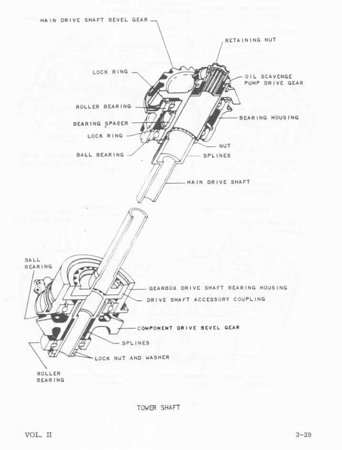
The reduction gear assembly is driven by a hollow steel tower shaft extending down through the 6:00 o'clock strut. The upper end of the tower shaft splines into the main drive shaft bevel gear and coupling. This gear meshes with the bevel gear on the rear hub of the N2 compressor.
The upper end of the tower shaft Is supported by two bearing assemblies, housed in the main component drive coupling. Tbe upper bearing Is a r oller type and accepts radial loads from the coupling. The other, also a ball bear ing, accepts both radial and thrust loads lroposed on the coupling by the compressor drive gear.
At its lower end, the tower shaft has a gear that meshes with a ring gear inside the lower coupling. This coupling is, In turn, spllned toto the inside of a bevel gear that meshes with a bevelled accessory drive gear in the gearbox.
The lower coupling and tower shaft assembly Is supported by two bearing
3-38 VOL. ll
MAIN DRIVE SHArT BEVEL GEAR
BALL
ROLLER BEARING
VOL. il
RETAINING NUT
LOCK RING OIL SCAVENGE PUMP DRIVE GEAR
ROLLER
LOCK RING
BALL BEARING
t~'--GEARBOX DRIVE SHAFT BEARING HOUSING
DRIVE SHArT ACCESSORY COUPLING
CO~~ON(NT D~IVE BEVEL G[A~
SPLINES
NUT AND WASHER
TOw'ER SHAfT
3-39

STA~T[~ O~ I V[ I[A~ I NQ ACC tSSDIIY AND COM,ONINT DUT[II IIAC[ D~IY[S 8[Y[L Q[AIIIHAtT
HYDRAULI C 'UN' DIIIYI QIAII
tu[L ''*' Dil l Y[ llAII I NQ OUT[II IIAC[ I DLlll OIAII
COtiTIIDL OII IYI eCAII INe OUTU ltAC[
3-40
ACClSSOIIT AND COM,ONINT DillY[ QIAIIIHAtT
IIIIATHlll . II<'[LL[II
STAIIT[II Dil l Y[ COU, LI NQ
Q[AIIeOII FIIDNT HOUSING
GEAR BOX GEAR TRAIN
TAC:HOIIITU NIYI etAa tU[L C:ONTIIOL
OI L ,UN, Dil l Y[ C: OU,LINe
VOL. U

assemblles located In the gearbox bearing adapter. The ball bearing accepts radial and thrust loads from the tower shaft while the lower roller bearing receives radial loads from the bevel gear.
The gearbox fastens to the diffuser with four mounting lugs, a positioning bracket, and two guide pins.
Mounting lugs are in pairs: one pair on the forward upper left corner, and the other on the upper right corner. Each pair slips over each side of a mounting link attached to the diffuser. When properly aligned, a pin can then be slipped through the lugs and the link. A clip retalnet· is used to lock the pin In position.
On the top center of the gear case, the positioning bracket slips between two lugs on the bottom of the dtffus.er case. Just aft of the positioning bracket are the two guide pins. When the case is mounted, the guide pins slide Into matching holes in the diffuser case properly aligning the gearbox.
The gearbox is then properly m'ated to the tower shaft and bevel drive gear assembl.v. Machined mating surfaces around the tower shaft assembly compress an "0" ring type seal when the gear case Is properly attached to the diffuser.
Accessories mount to pads on the front and rear faces. When mounted on the correct pad, the ·accessory is driven at the proper speed by the reduction gear assembly 1n the gearbox. All accessory drives are right hand when looking Into the drive pa.ds.
Drive ratios as compared to N2 compressor speed follow:
Starter CSD Hydraulic Pump N2 Tach Generator Fuel Control Fuel Pump Thrust Reverser Pump
0. 7000:1 o. 8020:1 0. 3420:1 0. 4350:1 0. 3480:1 0. 3440:1 o. 7000:1
Accessory locations on the forward face (viewed from the rear) are the fuel pump drive on left hand side, Constant Speed Drive (CSD) adapter pad in the center, and the fuel control drive on the right hand side. A duplex oil pump assembly is mounted internally between the CSD adapter pad and the fuel control drive.
On the upper left end of the accessory drive gearbox Is a pad for mounting the thrust reverser hydraulic pump. On the upper right end is a mounting pad for the engine oil filter (undrlven).
VOL. II 3-41

TO rtLlllt rJIOM r IL H~
SU,tt lY T•OM TANK
O IL PUMP ASSEMBLY
ruEL CONT~OL D~IVE
run PUMP O~IVE
O IL PRESSU~E ~ECULATING VALVE AOJUSlMENT
ENGINE ACCESSORY DRIVE GEAR BOX (fRONT VIEW)
TH~UST ~[VE~SE PUMP
C$ 0 AOAPTE~ PAO

< 0 r ~
BREATHER PRESSURIZING
STARTER DRIVE PAD
BEARING liNER
ACCESSORY DRIVES BEVEl GEAR SHAfT
ll CRAIN PlUG BOSS
(NGINE ACCESSORY DRIVE GEAR BOX (REAR VI£W)
HYDRAUliC PUMP DRIVE PAD

No.2 BEAR INC (OUPLtX)
No.6
No.4-1/2 No.3 BEARING
No.4 BEARING (DUPLEX)
No.2-1/2 BEARING
ENGINE BEARING LOCATIONS
No.5 BEARING

On the afl face of lhe accessory drive gearbox the following accessory drives or mounts are located. On the upper left hand side is the breather pressurizing valve pad and on the lower left hand side is the starter drive pad. The hydraulic pumps d1·ive pad is on the lower right hand side and on the upper right hand side is the N2 compressor tach generator drive pad. An oil drain plug is provided in the lower rear case just left of center.
ENGINE BEARINGS.
The rotating mass of the JT3D (TF33) engine, consisting of the compressor rotors , turbines, and turbine shafts, is supported by eight bearings. The No. 2 and 4 bearings are actually dual ball bearing units with each dual unit being considered as one bearing. By numerical reference, the bearings are the No. 1, 2, 2 1/2, 3, 4, 4 1/2; 5, 'and 6. The No. 2, 2 1/2, and 4 bearings are ball type used as thrust bearings. Ball bearings are used as thrust bearings as they can absorb both radial and axial loads. Remaining bearings are of the plain roller type as they absorb mainly radial loads.
NO. 1 BEARING.
The No. 1 bearing Is a roUe r type located Inside the compressor inlet guide vane assembly. The No. 1 bearing supports the front hub of the Nl compressor, and behind it is a spring-loaded carbon seal.
The outer race of the ~o. 1 bearing Is mounted inside a bearing support, which is bolted to o. flange located inside the compressor Inlet guide vane assembly. The outer race is held In the bearing support by a spanner nut which is locked by a rivet.
The lrmer race is mounted on the front hub of the Nl compressor. Order of assembly from the hub forward is a spacer, seal plate, bearing inner race, and then the spanner type retaining nut. The retaining nut Is riveted to the compressor hub. The inner race is wider than the rollers to allow for enging dimension changes due to varying temperatures.
Fastened to the same flange as the bearing support is a seal support assembly. The seal support has a spring-loaded, carbon-faced seal riding on pins to make an effective seal with the seal plate. In addition, a ring seal carrier fastens to the rear of the seal support . The ring seal carrier has grooves in its outer periphery for two metal piston-ring type seals to ride in. The piston ring type seals provide a seal for the floating carbon seal as It moves to remain in contact with the seal plate. The seal plate, being mounted on the compressor hub, moves as the engine rotor length changes due to temperature changes.
A seal between the compressor hub and seal support Is provided by multiple
VOL. II 3- 45

No.\ BEARING RETAINING NUT (INNER RACE)
No.\ BEARING RETA INING NUT (OUTER RACE)
OIL PRESSURE (4 0 1 CLOCK GUIDE VANE)
~H STAGE AIR
No.\ BEARING SCAVENGE PUMP
SCAVENGE OIL (8 0 1 CLOCK GUIDE VAN£)
NI.MBER 1 BEARING AND SEAL
3-46
SEAL
AIR CONTROL SEAL
VOL. II

lmife edges on the bearing spacer opposite the mside surface of the ring seal carrier, forming a type of labyrinth seal. :-linth-stage air Is bled through holes in the front hub and bearing spacer to a sm:tll cavity between the seal plate, the carbon seal, and the bearing spacer. Thi~ ninth-stage air pressurizes the car bon seal so that if any seal leakage occurs. it is air-to-oil. Some bleed air passes through the labyrinth seal, up the front face of the first N1 compressor rotor wheel and is reingested. Air bled through the ring seals, and the carbon seal enters the No. 1 bearing cavity and passes out the No. 1 bearing vent.
The bearing front face ls lubricated by an oil jet. The carbon seal and seal plate also are lubricated by another oll jet.
NO. 2, 2 1/2, AND 3 BEAJ.UNGS.
The No. 2 bearing (front compressor rear hearing), ~-o. 2 1/2 bearing (compressor intermediate bearing), anti the No. 3 bearing (rear compressor front bearing), are all located in the center section in front of the compressor intermediate case.
The No. 2 bearing ls a duplex ball bearing, the two bearings acting as one. They are a ma~ched set and both have split inner races to facilitate installation. The design of the split inner- race, duplex, nnnular- type bearing is unique in several respects.
A deep groove outer race Is used. There is no tendency for a ball to be damaged under high centrifugal forces or under hea\'Y thrust loads due to the elimination of a counter bore which wlll be found on some non-separable bearings. A split inner race permits a greater number of balls to be used without the need for a counterbore or notches. A one-piece machined retainer of maximum strength can be used. It may be inner or outer land riding, but preferably inner.
The bearing is completely separable lor vast: of Inspection and cleaning. The split-inner-race bearing has the ability to take high thrust loading in either direction while heavy momentary radial overloads may be carried.
In producing the inner race, the curvatur" ')f the groove ln each of the two halves is ground while they are separated by a sp::cer. When the bearing Is assembled, the spacer Is left out. This forms what is ~c.lled a "gothic arch. " The arch prevents the balls from rolling on the split Itself. If the ball is pressed radially inward, as when under a rad1al load, It ~o::1tacts the inner races on both sides of the split. This allows greater monentar) :-adlal overloads to be carried besides axial loads in either direction. For these reasons, split-Inner- race, annulartype bearings are used as thrust bearings. A duplex bearing of this type would gl ve twice the capacity in one unit.
VOL. n 3- 47

rRONT COMPRESSOR ORIYt TURBINE SHArT
(OUI'liNG
SNAP RING
No.3 BUR I NG S(A L CARR I tR
No.3 BEARING
No.2-l/2 StARING
No.2 DURING
riB[RGLASS
HtAT SHI tLD
12TH STAGE
AIR f) DUPLEX
9TH
STAG( -~::J~~~.~~~~~~~~~:;::~~ AIR ~ ~-
No.2 6tAAINC SEAL ( CAROON rACt TYPE)
SPRAY NOZZLE
NUT R INC
SPRAY NOZZ Lt 11 LAST CHAN Ct'' FILTER
Nl TURBINE SHAr T
SPLINt roR N2 COMPRESSOR SHArf
No.3 etARING StAL ( CARBON rACt TYPt)
OIL PRESSURE (6 O' CLOC K INf(RHtO CASt)
NUMillR 2, 2 1/2, AND 3 BEARINGS AND SEALS

The inner races of the bearing are separated by an oil baffle. In front of the bearlng, proper position Is maintained by a seal plate used as a spacer. The seal plate sets against the shoulder of a sleeve that has been slipped over the rear hub. The No. 2 be:lring races. seal plate and oil baffle all ride on the sleeve. They are held on the sleeve by a retaining nut that threads onto the rear hub of the Nl compressor.
The outer race of the dual bearing Is carried ln a bearing support that, In turn, is bolted to a flange of the compressor intermediate case. The outer race is retained by a retaining nut that threads into the bearing support.
Extending forward from the bearing support Is a heat shield and seal assembly. The seal Is comprised of a springloaded, floating carbon seal and seal plate with piston ring type seals.· Again, the piston ring type seals provide an air seal for the carbon seal as it moves to maintain contact with its seal plate. Ninth- stage air off of the rear of the Nl compressor pressurizes the carbon seal to prevent oil leakage.
Aft of the No. 2 bearing, the No. 2 1/ 2 and 3 bearing assemblies sit on steps In the rear hub of the Nl compressor.
The inner races of the No. 2 1/ 2 and 3 bearings and a spacer are retained on the hub by a spanner-type retaining nut. The nut, in turn, Is locked to the hub by a rivet.
To the rear of the· compressor intermediate case, a beat shield assembly and a rear bearing support Is fastened. Part of the heat shield insulates the rear face of the bear log support. The other part slips over the seal assembly, helping insulate it.
To the a ft loner flange of the rear bearing support, the No. 3 bearing carbon seal assembly fastens. Over the outside of this, the No. 3 bearing ring seal carrier fastens. The carbon seal is of the sprlngloaded floating type as before.
The seal plate assembly fastens to the forward end of the N2 compressor front hub, and is supported by the No. 2 l/2 bearing. The seal plate splines lnto the N2 compressor hub, and a snap ring retains the outer race of the No. 2 1/ 2 bearing inside the seal plate assembly.
Twelfth-stage air pressurizes the No. 3 bearing seal. The No. 3 bearing outer race is held between a shoulder on the Inside of N2 compressor hub and a shoulder on the rear of the seal plate assembly. The No. 3 bearing is therefore the support for the front bub of the N2 compressor .
Inside the diffuser case, the rear hub of the N2 compressor is supported by the
VOL. n 3-49

c.:> I
"' 0
16TH STAGE AIR fiBERGLASS HEAT SHIELDS
DiffUSER CAS[ IHN(R STRUCTURC
ACCESSORY DRIVE GEAR N2 COMPRESSOR REAR HUB
RETAINING NUT
~~~::~;t~~~~~==~~=:~::~~~~~~~~==~~~~~SNAP RING c TAB LOCK
Nl TURBIN( SHAfT ~-=========7~===5=P==AC=£=R==A=H=O==O=I=L===I=S=T=R==I8=U=T=O=R=====================
RING SEAL ASSEMBLY
9TH STAG[ Alii>
CARBON SEAL SEAL P LATE &£Alii HG
fiNAL SCREEN fiLTER
O I L PRESSURE (4 0 1 CLOCK DiffUSER STRUT)
NUMBER 4 BEAR ING AND SEAL

No. -1 bearing. The No. -1 bearing is a duplex ball type sim tlar to the No. 2 bearing.
The Inner races of the No. -1 bearing are of the spilt type and slip over the outer diameter of the rear hub of the N2 compressor. Fr om a shoulder on the rear hub aft, the order of assembly is a seal plate, dual bearing Inner races separated by an oil baffle-spacer, spacer ring, bevel gear, and a retaining nut. The retaining nut is safetied to the rear hub by a splined locking sleeve and a snap ring to keep It engaged.
The outer race of the No. -1 bear ing Is mounted In a bear ing support-seal carrier fastened to a flange of the inner dlffuser case structure. To the forward end of the bearing support-seal carrier, the No. 4 bearing heat shield fastens. Just below this, the sprlngloaded floating carbon seal is located. Piston ring seals are again provided to seal the carbon seal as it moves to stay in contact with the seal plate during engine dimension changes.
Sb.:teenth-stage air passes down the rear face of the N2 compressor hub, around and under the heat shield, pressurizing the carbon seal so any leakage is air Into the No. 4 bearing cavity.
NO. 4 1/2 BEARING.
The No. 4 1/2 bearing Is mounted between the low speed (N1) and high- speed (N2) turbine shafts, and Is located approximately midway In the combustion section. It is a roller bearing used to minimize the whip of the long, low- speed (Nl ) turbine sbait.
The outer race Is extra wide to allow for changes in engine length due to temperature variations. The outer race is held against a spacer and the spacer against a shoulder Inside the N2 turbine shaft by a retaining sleeve. The sleeve threads Into the inside of the N2 turbine shaft .
The inner race of the No. 4 l/2 bear ing, a bearing spacer, and three carbon ring seals are held in place on the N1 turbine shaft by a castellated retain ing nut that threads onto the shaft . A tab lock retained by a snap ring locks the castellated nut to the Nl turbine shaft. To Index the tab lock to the turbine shaft, grooves are cut In the threaded portion of the shaft.
Three rotating carbon ring seals seal off the bearing preventing oil flow rearward. Sixteenth-stage air passes forward between the concentric turbine shafts and pressurizes the aft side of the r ing seals. Normally, any leakage Is airInto-oil.
VOL. IT 3- 51

4 t /2 BUR IN<i OIL TO SCAV(NG[ Su~P N2 TURBIN( SH Arf
A(TA IN IHC NUT 1 HOt X \lASHER
.... Oil PAt55UA( rROM No. 6 BAG
NlMlER 4 BEAR ING AND SEAL
'

\
NO. 5 BEARING.
The No. 5 bearing is a roller type, located just forward of the N2 turbine in the front center of the turbine nozzle case. This bearing supports the high-speed (N2) turbine.
The outer race and rollers are mounted In the bearing support housing. The bearing support housing splines into the bearing support and is also bolted to the inner combustion case heat shield. The Inner race is retained In the bearing housing by a spanner type retaining nut that is locked by a rivet to the bearing housing.
Against a shoulder on the N2 turbine shaft rides a spacer, seal plate, and the No. 5 bearing inner race. They are held against the shoulder by a castellated retainJ.ng nut that threads onto the turbine shaft. The retaining nut is safetled by a tab lock that locks the nut to the turbine shaft. The tab lock is retained Inside the nut by a snaprlng.
Oil flow aft is prevented by a springloaded floating carbon seal. The carbon seal assembly mounts to the seal support. The carbon seal is sealed by two, metal, ring- type seals. The ring seals and their carrier bolt to the aft Inner flange of the seal ;SUpport.
Kntie edges on the bearing spacer provide additional seal on the inner circumference of the ring seal carrier. Sixteenth-stage air pressurizes the ring seals and the carbon seal so leakage Is air into the No. 5 bearing cavity.
Lubrication for both faces of the bearing and the carbon seal is provided by three oil jets. A finned heat shield of swandwich construction is fastened over the bearIng assembly.
No. 6 BEARING.
The No. 6 bearing is a roller type located in the turbine exhaust case. It supports the rear of the low-speed (Nl) turbine.
The No. 6 bearing inner race, rollers, and seal assembly are mounted on the rear hub of the Nl turbine. From a shoulder on the rear hub aft, the buildup sequence Is two seal spacers and carbon seals, seal plate, No. 6 bearing Inner race, and rollers. These are retained by a flange on the pinion drive gear for the No. 6 bearing oil scavenge pump. The pinion gear Is bolted to the carrier sleeve for the oil transfer tube assembly inside the rear hub. The carr ier sleeve Is threaded into the inside of the rear hub.
The outer race is held in the bearing support by the turbine rear bearing heat
VOL. II 3-53
--

BEARING SUPPORT
riBERGLASS H[AT SHIELD
BEARING SUPPORT HOUSING
No.5 BEARING
RETAINING TAB
SNAP
SCAVENGE OIL (PUMP AT No.4 BEARING
OIL PRESSURE
(rROM N0.4 BEARING)
INNER COMBUSTION CASE HEAT SHIELD
INNER COMBUSTION CASE
SPLINE
BEARING SPACER
RACE
SPRAY NOZZLE
NUMB(R 5 BEARING AND SEAL
SEALS
riBERGLASS HEAT SHIELD
REAR COMPRESSOR DRIVE
TURBINE SHArT (N2}
CARIION SEAL
(rACE TYPE)
Nl TURBINE SHArT
SUPPORT

< 0 r t:l
No.6 BEARitlc
CAS SEAL
rRONT COMPRESSOR------~~-~~ DRIVE TURBitiE ?'-.--./1
ROTOR REAR HUB
TO #4-1/2 BEARING
AND SEALS
No.6 BEARING SEAL
NUMBER 6 BEARING SEALS AND OI L SUMP
OIL PRESSURE (3 0 1 CLOCK,
EXHAUST CASt)
riNAL SCREEN r IL TER
SCAVENGE O I L AND AIR
(7 O'CLOCK,
EXHAUST CASt)

shield support which bolts to the bearing support.
The forward carbon seal Is preloaded by ninth-stage air from the inside of the hollow turbine shaft. This air Is bled off to the outside and forward faces of the carbon seal through a passage In the turbine shaft. The other carbon seal Is sprlngloaded by a spring washer. In addition, ninth-stage air pressurizes the seal assembly on Its forward side so leakage Is air-to-oil.
Lubrication Is provided for the forward face of the bearing by an oll jet. Complete Information on bearing lubrication Is covered under Engine Lubrication, Chapter IV.
3-56 VOL. II