Embed Size (px)
Citation preview

1
Volume 3 Issue 2 Published by Lee Thevenet March-April, 2011
HORSELESS CARRIAGE REPLICA NEWSLETTER
A Publication dedicated to the reporting of news, events, articles, photos, items for sale, etc, having to do with replica horseless carriages.
Newsletter published six times a year and special issues when needed.
From the Editor Hi Everyone, With the Christmas / New Years Holidays behind us and the winter months just about gone, I think most builders will once again prepare to start planning and building. This is the time of year I am in the planning stages and that always includes the Chickasha Pre War Swap Meet in Chickasha, OK. I am always looking for interesting parts I can use on my next build or a really neat oil lamp for one of my finished carriages. I can not even start to explain all the terrific prices of usable HCR goodies at this event. There are also meetings for the various clubs, as the National CDO Club of America, the Early Ford Registry Club, the Model T Ford Club of America & the Horseless Carriage Club of America. The folks that are members of these fine organizations have a wealth of information any builder can use just for the asking & will gladly allow guests at their meetings. By the time this HCR News Issue is posted, I will already making arrangements for the 2-3 day stay there. This event is at the top of my “to do” list for 2011. This would be a perfect location for a yearly HCR Meet for members of the surrounding area or states as some of us did last October in NC. Lets talk about the possibilities & who would be interested on the HCR Builders Group Blog before it’s too late.
The information on the Swap Meet and area map are on the next page, along with a few pictures of some items found there…
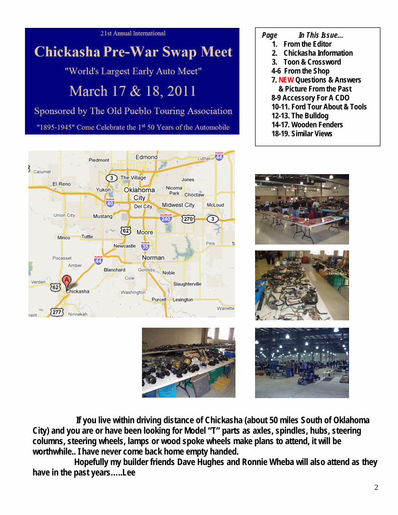
2
If you live within driving distance of Chickasha (about 50 miles South of Oklahoma City) and you are or have been looking for Model “T” parts as axles, spindles, hubs, steering columns, steering wheels, lamps or wood spoke wheels make plans to attend, it will be worthwhile.. I have never come back home empty handed. Hopefully my builder friends Dave Hughes and Ronnie Wheba will also attend as they have in the past years…..Lee
Page In This Issue… 1. From the Editor 2. Chickasha Information 3. Toon & Crossword 4-6 From the Shop 7. NEW Questions & Answers & Picture From the Past 8-9 Accessory For A CDO 10-11. Ford Tour About & Tools 12-13. The Bulldog 14-17. Wooden Fenders 18-19. Similar Views
3
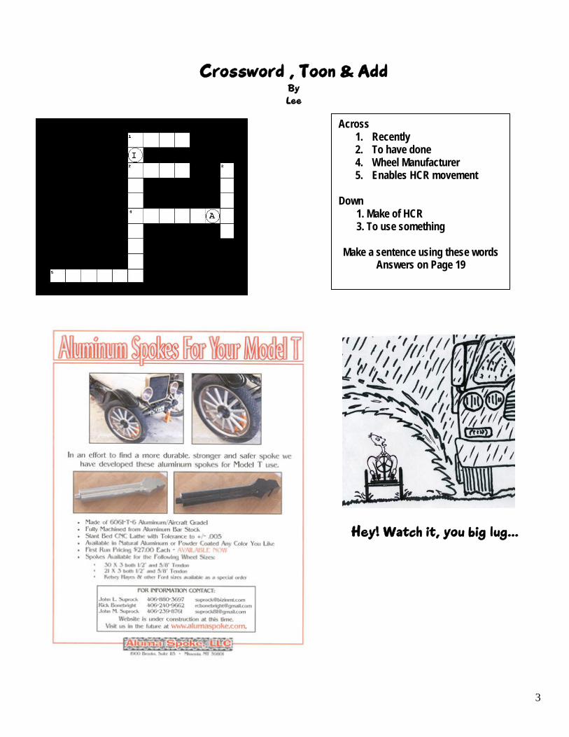
Crossword , Toon & Add By Lee
Across 1. Recently 2. To have done 4. Wheel Manufacturer 5. Enables HCR movement
Down 1. Make of HCR 3. To use something Make a sentence using these words
Answers on Page 19
Hey! Watch it, you big lug…

4
From the Shop
This time fellow builders & readers we go back in time at two Interesting articles from the pages of Everett Moore’s
“Builders Handbook” by our Ford man Robert Kapela… (the article has been re-edited & re-formatted to fit the HCR News format)
All about Roller Chains
by Robert Kapela I have read about some roller chains breaking. This is disturbing, and depending where
the brakes are located, can be — and has proven to be — dangerous. Some information about roller chains: Roller chain drives are intended for power transmission between two or more parallel shafts on short or medium centers, with relatively low speed driving units. "Browning chain drive engineering". The capacity of a chain drive is determined by the speed of the smaller sprocket, the number of teeth in the smaller sprocket and the chain size. Horsepower ratings are based on a normally lubricated setup. A lot of the replica cars use #41 roller chain (maybe, because it is easily available from Northern and others?). Size #41 chain has a tensile rating in pounds of 2000. Even size #35 (I can't figure this out) has a rating of 2100#. However, if you upsize to size #40 (same 1/2" pitch as #41) your tensile rating just about doubles to 3700#. Size #50, maybe overkill, is rated at 6100#. I really recommend using size #40 sprockets and chain, and good quality chain at that. I wouldn't settle for what's in the Northern book, you can find size #40 pretty easily. I would never even consider size #35. If you live in a farming area where there is a Tractor Supply Co., they have size #40 sprockets that are hub less, and you can buy a bored hub to fit, meant to be welded into the sprocket. There are other agrisupply places around, or you can go to the internet and look up where Browning, Morse, Woods, or others can be purchased. If you go way back to issue #23, one of my first articles, I talk about it being important to gather up a small library of supply catalogs. This practice proves to be very helpful also the technical articles are golden. This may be the only car you will ever build, so take a little extra time to get the sprockets and chain with which you will be more comfortable.
When roller chain drives are rated, the engineer looks at the application to put a "factor" in his rating. If an internal combustion engine is involved, the rating has to be downsized by a factor of 1.4, if the engine is driving a hydraulic unit, and as high as 1.7, if it is driving a mechanical setup (most of ours are in this category?) I did a few horsepower ratings just to show how chain size changes the ratings and they are as follows: A 20 tooth small sprocket at 300 rpm: Size #35 chain = .93 hp, size #41 chain= 1.21 hp. and size #40 chain = 2.21 hp. These readings are before the factors are considered. They are not too useful to us as shown, but demonstrate the improvements in ratings when chains are upsized. The other thing that has an effect on chains breaking is the tension in which the chain is running. Initial installation should have the chain slightly tight. After a short amount of use, the pins, etc., will "seat" and you should have a operating system with just a bit of slack in the idle side.

5
Avoid loose chains, they can easily be the cause of double the amount of shock delivered to the chain by the power unit, when it is suddenly accelerated or slowed. If the alignment of the drive is not what it should be, loose chains can easily "jump off", and we will maybe read about this.
Good practice includes keeping the chains lubricated. Of course, the initial setup should have everything in alignment. Avoid "offset" or "half" links. They are usually used because the person that first installed the drive did not do his homework. When I setup a drive- on the mounting plate, I always mill some adjusting slots in it so the drive can be adjusted in the future. I put the chain on temporarily, between the two shafts and check to be sure that the chain will be tight when I weld the mounting plate down, with plenty of adjustment left for the future. If you are using a very small sprocket to drive a large one, and the distance between the two is short, you may have a problem. At least 120 degrees of the driving sprocket should have "chain wrap". That is, at least 1/3 of the teeth should be engaged. Very small sprockets (number of teeth) should always be avoided as much as possible, as they are the most important factor in figuring horsepower ratings, capacity, etc.. A word of caution: Roller chain sizes #41 and #40 have the same (1/2") pitch. Size #40 is a little wider and will actually fit on #41 sprockets. Size #41 will only fit on #41 sprockets. I don't recommend at all anyone putting #40 chain on their existing #41 sprockets, thinking that they have just upgraded the capacity of their drive unit. Doing so just opens up a can of worms, and not only is the capacity of the drive compromised, now you would have to deal with side slop and possible "chain climb". If you are going to upgrade, do it all the way for your safety. Keep your chains adjusted…
More about Roller Chains by Robert Kapela
Chain drives, properly-sized and installed, are a very reliable and inexpensive way to operate a power transmission system. Setup your drive correctly, maintain it, and enjoy the rewards of trouble-free operation for your efforts. (For effect, I will describe some extreme situations, found in industrial operations, that operate mostly non-stop, for extended periods.) You should only have to readjust your chains once per year or season. If you find that your chains need adjusting frequently, this is something you cannot afford to ignore. It could mean that your drive is under engineered and needs upsizing from size #35 or #41 to size #40 or larger. If you are already at size #40, and still have problems, you have to do additional troubleshooting to see what is causing the problem. Where did you get the chain? If it is very inexpensive chain from some hard to pronounce country, this could be the problem. "Made in America" still means something; use high quality, name brand chain. Is the chain dry and shiny and does it kind of "snap" around the sprockets? This indicates the chain is dry and needs lubrication. The proper way to re-lubricate a chain is to remove it and soak it in medium weight oil overnight. When re-installed, how- ever, centrifugal force may throw some oil on your driveway and the underside of the machine. When you have the chain off, hold it in your hands and see if there is significant slop between each individual link. This will indicate the amount of wear. Lay the chain down full length and count the number of links. Then, compare the extended length of the chain section with a brand new section with the same number of links. The extra length of the old chain will soon tell you if and when it is time to re-chain.

6
When I was a maintenance engineer at Ford, I could get a $50,000.00 project approved for a new conveyor chain installation, based on the measurements of a couple of 10 link sections of chain alone. That is how reliable and recognized this test is. To further explain this, for example, your size #40 chain has 1/2" (.500") pitch. The chain, usually, wears faster than the sprocket teeth, which remain at proper .500" pitch longer, unless the sprockets are very soft. As chain-wear progresses, it’s true pitch distorts, measured across several links from .500" to .505", then .510", etc. There comes a point when you can not properly adjust the chain to make up for this wear. As you tighten the chain, it will start to climb up on the sprocket teeth. Replace long before this.
Other factors that accelerate chain wear include: combinations of a very heavy machine or one that has more than normal resistance to rolling (this would usually cause engine overheating), a machine carrying a heavy load, pulling a trailer, extended operation in sand or soft ground, machine is over- powered, or engine not running smoothly.
Again, avoid half or "offset links", remember that a chain is only as strong as it's weakest link.
Chain take-ups or tensioners are meant to keep tension on the slack side of chains
only in between periodical mechanical adjustments. They are nice, but not a cure-all and certainly not meant to compensate for unlimited chain wear and stretch. Check your sprockets. In industrial use, Engineers commonly specify sprockets with hardened teeth. They resist wear and maintain proper profile for much longer than plain sprockets (double this life). They are readily available. I don't think you will find them in the catalogs that are commonly mailed to your home.
Combined with low quality chain, soft sprockets can be a real problem. The builder loses in the end, because, now, he has to buy better quality parts to replace the original, or use the existing machine, sparingly. Soft sprockets with only 10-12 teeth can be especially trouble- some. Due to the torque of the drive, the teeth can distort and develop "hooks" at the outer tips. If you start to hear "snapping" sounds or the chain does not go around the sprockets smoothly, check for this. Although not common, a stone or other piece of foreign material can get caught in a link or between two sprocket teeth. You can correct this during your pre-ride inspection. If, during an inspection of your machine, you find a broken link, missing roller, or some- thing else, it is a poor practice to just replace the one bad link. Go all the way and replace the entire chain.
Try to use sprockets with split-taper bushings instead of straight-bored ones. They cost more but are by far the better choice. Split taper bushings, properly-installed, grip the shaft some 20 times greater than straight bored ones, yet are much easier to remove or readjust. Now we are all experts on chain drives! Good driving. Bob Kapela

7
Questions & Answers
In a recent E-Mail from a HCR Builders Group member and reader of the HCR News, I received a suggestion that I should add a new topic to the HCR Newsletter. Namely; “Questions & Answers”. Even though I regularly invite the HCR members and Newsletter readers for input to the Newsletter, this was the first time a “suggestion” was offered… Credit goes to reader, Robert Shannon of Camden, TN… Mr. Shannon is a teacher at the Benton County Career & Technical Center. Question: “Even though I am a licensed contractor and finish a lot of cabinetry, I don't know the best way to paint the woodwork on the Olds so that over time, as the wood takes on more moisture in the summer and expands, it won't be as likely to start cracking & peeling”… How can this be avoided?... A good article on this subject would be very helpful… How about it, HCR Builders Group members, could we kick this subject around on the HCR Builders Group blog or possibly come up with an answer or member article for the next issue of the HCR News? Lee
Picture From The Past

8
An Accessory For A Full Size CDO by
Lee Thevenet
While going through some reprints of some early Oldsmobile advertisements I recently acquired, I ran across this beauty. Apparently an accessory offered in the first couple of years of the Olds Motor Company’s production. The only text offered is what appears underneath the picture. Judging from what is shown, the CDO carriage appears to be 1901 to late 1903 due to the absence of fenders & having wire wheels. It most likely led to enough interest by shop keepers & delivery carriers to urge Ramsey Olds to begin designing & eventually manufacturing the larger size delivery, or the one we refer to as the “Pie Wagon” Builders who already have built or plan to build the “Full Size” CDO using the plans by this author possibly might be interested in adding this smaller version of the “Pie Wagon Body” to the build, that will give their CDO HCR a completely fresh look. The light cargo body would be detachable and would simply install where the rear deck is. To install would require temporally removal of the rear deck lid. Continued on next page…

9
With that in mind, I took the liberty to come up with some workable profile measurements that could be used to build this accessory to the CDO Runabout body. Using a light 1” X 2” framework & ¼” Luan plywood for the sides & top should work out real well….:) The width measurements would be that of the CDO body, 30 1/ 8”… Enjoy, Lee

10
Ford Tour About by
Earl Brown Hello All, My name is Earl Brown of Lake Tapps, Washington. I am presently building my second HCR Carriage. My first build was a Jimmy Woods, single seat HCR with a 16.5 B&S engine. My family has enjoyed riding it in many parades since I completed the build. Being a single seat carriage capable of two adult passengers, it was decided the next carriage build would seat four. For my second build, I selected on the 1906 Ford Model “N” to be built using Lee Thevenet’s Plans. The 1906 Ford “N” did not come with a rear seat therefore, there would be modifications made to the build. To achieve this I would have a frame length of 116”overall and a frame width of 23” and a body width of 31 ¾”. I used the plans as they were except I substituted a rear seat instead of the trunk area. That worked out well, giving the carriage an additional seating capacity of two more adults or three children. I used a Model “T” front axle, four “T” wood spoke wheels and a “T” steering column and steering wheel. The transaxle at the rear is a Eaton Hydrostat mated to the “T” wheels. The HCR sports a Kohler 14.5 hp, electric start. The coil box on the firewall is built from Lee’s plans and features the ignition switch and amp meter.
Presently I have not yet determined on what fuel tank I will use & where to install it. Some other items still to be done are, Brakes, exhaust system, fenders & upholstery. This has so far been a really enjoyable build. Earl Brown Lake Tapps, WA More pictures to follow…

11
I also received another really nice E-Mail from Earl recently …as follows… The HCR Builders Group is great, Don Bowers, also a member, has helped me a lot. I don’t know what I would done without his help. Lee, I want to thank both you and David Hibbitts for all the help and information you both gave me. Like I have always said “This Group really works” Earl Brown Lake Tapps, WA
Tool Time By Lee Readers, watch for this savings coupon in the mail. I just recently purchased this neat set of “Step Drill Bits” and they are Great!

12
Readers, An E-Mail I received recently led to the next article… Hello Lee, It’s has been some time since we corresponded. I’m John Johnston from Michigan who emailed you and then we talked over the telephone. I was asking for assistance in building an HCR.... It’s been completed and this last year we drove it in several parades in this area. I have a couple photos attached that show me and the family enjoying it this last summer. Just thought I would drop you a line and show you how the project turned out. I wanted to thank you for providing me the inspiration, and let you know that I and the family have really enjoyed it. I have a couple bugs to work out yet but will be enjoying it for many years.. Thanks again, A friend always John Johnston
The “Bulldog” By
John Johnston Hello everyone, My name is John Johnston of Michigan. I’m the Facilities Director of a four year Methodist College. The College’s mascot is a “Bulldog”, so we named her as made by the Bulldog Motorcar Co. Since completion, we have made era costumes of the 1900’s and have participated in many parades and events. Here are some pictures of the “Bulldog” and the family enjoying her. PS: Thanks Lee for the interest and response. It was some project but well worth all the time and effort that went into it…
John & Father in Law Bill…Bill & his wife Liz (in next 2 pictures), are from Florida

13
Again, many thanks to you Lee for answering my E-Mail, and phone call which provided me more inspiration than you realize. A friend always, John Johnston
Do you know the year & make of this horseless carriage? A “FREE” set of my HCR Plans to the first person to answer correctly… Lee
John & his Mother in Law Liz & “Roxie”
John, Vickie & Daughter Jordan The “Bulldog”

14
Wooden Fenders By
Lee Thevenet In the early days of the automobile there was as much as a thousand different makes of autos. Sometimes being no more than a horse drawn buggy that had been converted from being pulled along by an average horse to being pushed along using some form of propulsion unit in its earliest form of development. Folks coined the name “Horseless Carriage” and they proved to sometimes be very unreliable. Even when everything was running well, they were very noisy to say the least. So noisy, that early makes of the autos had to pull to the side of the roadway and shut off their motors when encountering horse drawn traffic. The body’s or passenger compartments of these early forms of transportation were mostly constructed of wood. Frames & other components were of metal. However some makes sported wooden fenders instead of the normal metal counterparts. One of these makes was the REO. Being a builder in the hobby of Horseless Carriage Replicas, I strive to make my creations as close to an original as reasonably possible, in looks, at least. Getting very close to completing my 1906 REO Runabout replica, it came time to build the fenders. Wood or metal was the choice. Already having the needed metal sheeting to do the job, I had to weigh the decision of purchasing additional material to get it done. Since the model I was building originally came with wooden fenders from the factory and staying with the principle of accuracy, the choice just had to be wood. A bit of research indicated the fenders needed to be 3/8” thick. That would mean laminating 12 pieces of 1/8” plywood together. Three pieces, for each of the four fenders. I was able to purchase three sheets of 1/8” Luan plywood from a local shop owner for $8.50 a sheet. I had previously checked with Lowe’s & The Home Depot stores, but what they call 1/8” is really fifty thousandths thick & costs almost three times more. Now the trick to making wood stay curved in the correct shape, is to layer different pieces together to form one. The trick to doing that is to have a fixture (buck) to build onto. This fender building process would require three “Bucks”. One for the two rear fenders, since those two fenders were identical and two for the front fenders, because the front fenders each curve in opposite directions at the rear edge.
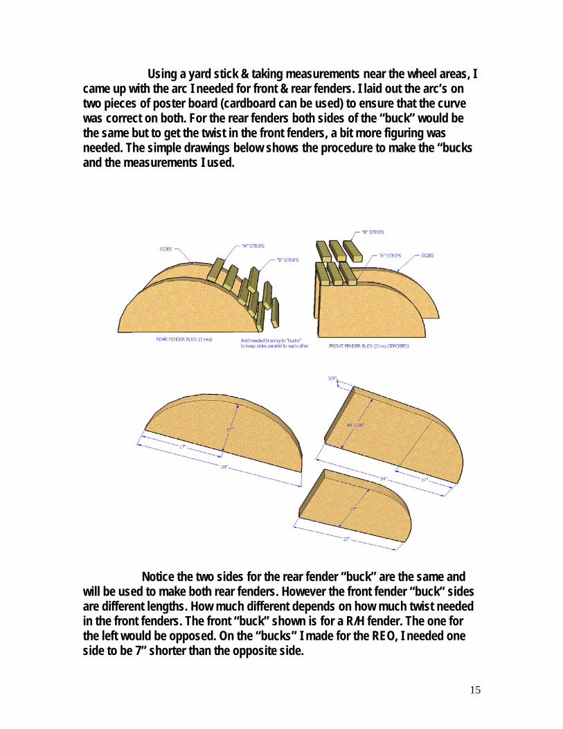
15
Using a yard stick & taking measurements near the wheel areas, I came up with the arc I needed for front & rear fenders. I laid out the arc’s on two pieces of poster board (cardboard can be used) to ensure that the curve was correct on both. For the rear fenders both sides of the “buck” would be the same but to get the twist in the front fenders, a bit more figuring was needed. The simple drawings below shows the procedure to make the “bucks and the measurements I used. Notice the two sides for the rear fender “buck” are the same and will be used to make both rear fenders. However the front fender “buck” sides are different lengths. How much different depends on how much twist needed in the front fenders. The front “buck” shown is for a R/H fender. The one for the left would be opposed. On the “bucks” I made for the REO, I needed one side to be 7” shorter than the opposite side.

16
Space the wood strips “A” uniformly along the curvature of the “bucks” from one end to the other. The “buck” sides can be made out of particle board or other economical material (better quality material should be used if several sets of fenders are to be made). Wood strips are 1” X 2” pine purchased at Lowe’s. Make the “bucks wide enough so they are wider than the fender pattern you are using. The “A” & “B” strips should be the same width so they can be tightened down with drywall screws on the ends, to put pressure on the layers of fender material. Once the “buck” fixtures are finished, they should be covered with scrap ¼” plywood (as shown below on the right) to prevent the wood strip pattern from transferring on to the finished fenders. The actual bucks I made and used, are shown below, both after being stripped & also after they had been covered with scrap plywood.
The pattern for the top of each fender should be transferred to the 1/8” plywood with the grain running with the fender pattern. Cut out one top piece for each fender. Transfer patterns as to conserve material.

17
The pattern should be turned across the grain of the plywood for the center pieces and then once again the pattern should be running along the grain for the bottom pieces. The grain should be opposed for each layer. Notice in the lower picture on the previous page, that only the top fender piece is cut to the pattern size. The second & third layers should be cut a bit larger than the top layer to make allignment easier when gluing up. After all pieces are cut, number the layers for each fender and stack in order seperately. When gluing up, coat the entire top part of the lower piece first. Coat both sides of the center piece and place on the bottom piece. Coat the bottom of the top piece, flip over and place on top of the other two. Place the entire assembly on top of the correct “buck” (a helper would be great). Allign pieces accordingly and put the first “B” strip on one end of the assembly and screw down both ends into the matching “A” strip, but outside of the pieces. Working from one end, continue to attach all “B” strips, working toward the other end of the “buck”. Place something (paper, cardboard) on the floor surface to catch glue being squeezed out. Do not wipe excess glue with wet cloth, as it will delute the glue. Allow to drip onto floor protectant. Allow at least 36 hours to completely set up undisturbed. This will assure a good bond between layers. Once completely dry, remove fenders from “buck”, trim accordingly following the outer edge of the top layer, sand thoroughly around edges (careful of splinters). If transfer of strips occur, correct using auto body filler. Temporarly re-install fenders on “bucks” for bodywork, temporary legs can be added to facilitate working….End…..Enjoy!
With the curvature of the fenders, the “bucks” serve a second role by providing a sanding fixture for the new fenders…
After the filling & sanding of the irregularities, the new fenders are ready for primer and painting
18
Similar Views I recently went back through some of Everett Moore’s writings that I collected when he was publishing the E&W Newsletter. This particular piece in Issue No. 10 Engine and Wheels Page 5, got my attention. He is of coarse speaking of the former E&W website in the piece.
— Some final thoughts — By
Everett Moore I am pleased to see an increase in input from our readers. Also, the traffic to the web site is increasing. We are doing a few “link trades” with other websites. Little by little more people are coming to realize that they aren’t alone in their attraction to building a replica horseless carriage or “old car.” I am, also, glad to learn of others referring people to the website. When I started the website (about a year ago) I wanted to create a place where all could come to learn and share experiences and knowledge with others of the same interest. There seems to be a large number of designers and builders who create for their own enjoyment without the idea of creating plans for others. What we need is more of these people to become draftsmen and make their plans available. If anyone out there fits this category, get in touch with me and I’ll aid you every way I can to see your plans come to life. Till the next issue — Everett Moore Issue No. 10 Engine and Wheels Page 5 Editors Notes… Not long after Everett decided to end the E&W Newsletter publication, I started the HCR Newsletter (with Everett’s blessing) so the builders could have a place to show the world pictures and articles of their builds, continue bringing the HCR movement forward and making our ever growing numbers visible to the world. The HorselessCarriageReplicas.com “website” provides a place for builders, as myself and others to display building plans for HCR’s, both free & for sale. More importantly, the website allows unlimited storage for the HCR Newsletters and members home videos (of their HCR’s). All at no charge to the builders or plans designers.
19
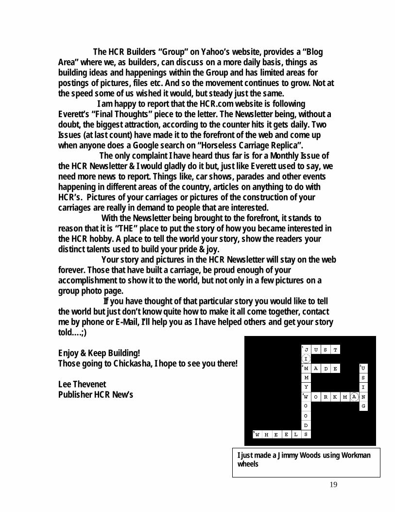
The HCR Builders “Group” on Yahoo’s website, provides a “Blog Area” where we, as builders, can discuss on a more daily basis, things as building ideas and happenings within the Group and has limited areas for postings of pictures, files etc. And so the movement continues to grow. Not at the speed some of us wished it would, but steady just the same. I am happy to report that the HCR.com website is following Everett’s “Final Thoughts” piece to the letter. The Newsletter being, without a doubt, the biggest attraction, according to the counter hits it gets daily. Two Issues (at last count) have made it to the forefront of the web and come up when anyone does a Google search on “Horseless Carriage Replica”. The only complaint I have heard thus far is for a Monthly Issue of the HCR Newsletter & I would gladly do it but, just like Everett used to say, we need more news to report. Things like, car shows, parades and other events happening in different areas of the country, articles on anything to do with HCR’s. Pictures of your carriages or pictures of the construction of your carriages are really in demand to people that are interested. With the Newsletter being brought to the forefront, it stands to reason that it is “THE” place to put the story of how you became interested in the HCR hobby. A place to tell the world your story, show the readers your distinct talents used to build your pride & joy. Your story and pictures in the HCR Newsletter will stay on the web forever. Those that have built a carriage, be proud enough of your accomplishment to show it to the world, but not only in a few pictures on a group photo page. If you have thought of that particular story you would like to tell the world but just don’t know quite how to make it all come together, contact me by phone or E-Mail, I’ll help you as I have helped others and get your story told….;) Enjoy & Keep Building! Those going to Chickasha, I hope to see you there! Lee Thevenet Publisher HCR New’s
I just made a Jimmy Woods using Workman wheels