Embed Size (px)
Citation preview

NASA Contractor Report 189205
Advanced Controls for Airbreathing EnginesVolume 3
Allison Gas Turbine
R.M. BoughAllison Gas Turbine Division
General Motors Corporation
Indianapolis, Indiana
July 1993
Prepared forLewis Research Center
Under Contract NAS3--25459
National Aeronautics and
Space Administration
(NASA-CR-189205) ADVANCED CONTROLS
FOR AIRBREATHING ENGINES w VOLUME 3:ALLISON GAS TURBINE (General
Motors Corp.) 43 p
N94-12272
Unclas
G3/07 0176733
https://ntrs.nasa.gov/search.jsp?R=19940007800 2018-06-01T05:57:47+00:00Z


Sec on
1.0
2.0
3.0
4.0
5.0
6.0
TABLE OF CONTENTS
Summary ..................................................................................................................... 1
Introduction ................................................................................................................ .2
Analytical Model ....................................................................................................... 33.1 Reference Model Aircraft ................ •............................................................... .33.2 Evaluation Criteria ......................... . .............................................................. .5
3.3 Mission Profile Study Points ............................................................................ .5
Controllable Advanced Propulsion Concepts .................................................................. 74.1 Combustor Variable Geometry Concept for Air-Breathing Engines ..................... 7
4.2 Compressor Variable Geometry ........................................................................ 114.2.1 One-Engine-Inoperative ....................................................................... 114.2.2 Reduced Surge Margin .......................................................................... 12
4.3 Wiggling Vanes and Surge Control .................................................................... 134.4 Turbine Variable Geometry .............................................................................. 154.5 Pattern Factor Control Using an Active Fuel Control System .............................. 204.6 Active Control of Chargeable Cooling Air ......................................................... 234.7 Performance Seeking Control ........................... _................................................ 27
4.7.1 Optimization process ............. !............................................................. 314.7.2 Advanced Propulsion Control Concepts Benefits ................................... 324.7.3 Additional Work ................................................................................. 34
Discussion of5.15.25.35.45.55.6
Results .................................................................................................... 35
Emissions ......................................................................................................... 35SFC ................................................................................................................. 35OEI ................................................................................................................. 37Life ................................................................................................................. 37
APC Management ............................................................................................. 37Summary ......................................................................................................... 37
References ................................................................................................................... 38

12345678910111213141516171819202122
23
LIST OF ILLUSTRATIONS
Potential civil tiltrotor designs ................................................................................... .4Civil tiltrotor mission profile ...................................................................................... .5CTR-22C .................................................................................................................... .5
Combustor variable geometry block diagram ................................................................. 9Combustor variable geometry ....................................................................................... 11Compressor variable geometry block diagram ............................................................... 13CVG benefits for reduced surge margin ........................................................................... 14W_/iggling vanes" block diagram .................................................................................. 16"Wiggling vanes" performance benefits .......................... 17Circumferential wave disturbance ................................................................................ 17
"Wiggling vanes" actuator location ............................................................................. 18Turbine variable geometry block diagram .................................................................... .20Turbine variable geometry potential at cruise .............................................................. .21Turbine variable geometry potential at takeoff ............................................................. 21Turbine variable geometry hardware ........................................................................... .24High stability combustor actively controlled fuel injector ............................................ .25Active cooling air control .............................................................................................. 29Active cooling air control hardware concept ................................................................. .31Active cooling control block diagram ............................................................................. 32Simplified engine/rotor control block diagram .............................................................. 33Propulsion system control loop with PSC (Level 1)......................................................... 34Total aircraft control loop with PSC (Level 2) ............................................................... 37Summary of results ....................................................................................................... 42
ii

Table
III
IIIIIIIV
LIST OF TABLES
Title
Evaluation criteria ..................................................... . ................................................ 6
Mission profile study points .......................................................................................... 6Combustor variable geometry components list ................................................................ 9CVG components list ..................................................................................................... 13Turbine variable geometry components list .................................................................... 19
Weight of active cooling concept hardware implementation ......................................... _.6
iii


1.0SUMMARY
This report provides quantified measures of performance and operability improvement resulting fromthe application of advanced control technologies to an airbreathing engine as part of the ongoingAdvanced Propulsion Concept (APC) program. The model aircraft of study was a 39-passenger civiltiltrotor based on the military V-22 Osprey, which utilizes two Allison T406 engines. A takeoff pointand a maximum cruise point were selected from an expected civil mission profile to simplify this first-
pass quantitative analysis. The engine performance and operability parameters examined werespecific fuel consumption (SFC), engine weight, engine acquisition cost, maintenance, emissions, and
safety.
Concepts were examined to reduce emissions in anticipation of stringent FAA regulations. Critical com-bustor design conditions are idle and maximum power conditions since carbon monoxide (CO) andunburned hydrocarbons (UHC) tend to be high at idle while nitrogen oxides ('NOx) are high at maxi-
mum power. Current fixed-combustor design yields acceptable emissions at maximum power yet muchimprovement is needed at the idle point. By controlling combustor fuel/air ratio, via variable geome-try, reductions of CO by 53% and UHC by 69% were calculated at idle with no effect on the maximum
power conditions.
Concepts were examined for improved SFC. Massachusetts Institute of Technology (MIT) has donestudies with regard to surge inhibitor technology which enable operating the engine nearer the surgeline. Reducing the surge margin, through compressor variable geometry vane settings, by 5% it was seenthat a 0.7% decrease in SFC resulted. Incorporating gas generator turbine variable geometry, to allow
varying flow by 10%, an improvement to SFC of 1.3% was achieved. Implementation of hardwareallowing active cooling control also yielded a 1.3% improvement to SFC.
Concepts were examined for improved one-engine-inoperative (OEI) capability, an important safetydesign criteria. At high compressor corrected speeds, 0.5% increase in horsepower was attainablewhile power turbine-turbine variable geometry yielded a 5.8% increase or 400 horsepower. The benefitof this concept provides either an increase of safety margin or a dynamic potential for downsizing the
engines yielding less weight for the same power.
A concept was examined to control combustor pattern factor. An actively controlled fuel nozzle systemwould allow for control of combustor circumferential pattern factor control. It was found that with 36%
reduction in pattern factor the maximum burner outlet temperature could be reduced by at least 100°F.This relates to an increase in turbine component life in excess of 100% which reduces maintenance cost.
Alternatively, the engines could be run hotter, thus providing additional power output.
Performance seeking control (PSC) was studied as not only an engine controller but as an outer loop forcombining airframe and engine in the optimization analysis. Although beyond the scope of this reportto quantify, PSC is expected to improve any other APC performance benefit as well as optimize thecoordination of any combination of implemented APCs.
Resizing the engine to reduce weight as a trade-off to SIC benefits was examined. Weight and costdeltas for each APC are presented whereas quantified measures of maintenance were deemed beyond
the scope of this report. For this commercial application the effects of APC implementation weresummed as sensitivities to direct operating cost. This is not intended to be a final ranking of the APCs
but simply one method of recording the results. It is recommended that a downselect process be per-formed on the basis of this report and that further, more detailed analysis be conducted by way of com-
puter simulation and if appropriate, eventual engine implementation and testing.

2.0INTRODUCTION
Theapplicationof advancedcontrolstechnologiesto airbreathingenginesofferspotentialfor signifi-cantimprovementof performanceandoperability.Detailedstudiesareplannedby NASAasapartofthe APC program to provide detailed quantified measures of such improvement for engine control fea-tures. Task 3 of the Unique Systems Analysis program, entitled Advanced Control for Airbreathing
Engines, successfully completed a preliminary screening of some 27 APCs against three model aircraft.From the results of Task 3, Task 6 (Phase II) continues the study, in greater detail, of the eight most
promising APCs against a single model aircraft. The purpose of Task 6, under same title as Task 3, wastwofold: provide a starting point for quantifying the benefits of each APC and gain insight into thebest methods of further detailed studies.
This program was divided into the following five tasks:
. Task 1: Define Aircraft--The results of Task 3 led to the selection of the Civil Tiltrotor becauseof it's common interest to NASA and Allison and because of it's excellent potential for future
demonstration programs. The mission profile was already well-defined such that operation
points could be easily chosen, with technical baseline information readily available. Specificaircraft/engine details can be found in Section 3.1 of this report.
• Task 2: Establish Evaluation Criteria--To obtain an evaluation criteria for ranking the net bene-fit of each APC, two types of information were considered, namely, aspects which could be easily
quantified and those which could not. Specific fuel consumption benefits could be determinedfairly easily with quantified numerical approximations. However, isolating the effects of indi-vidual hardware maintenance on overall aircraft maintenance costs, for example, is a difficult,
costly process beyond the scope of this effort. So, whenever possible, an impact to direct operat-ing cost (DOC) is shown and the other effects are described as best as possible. Details on theevaluation criteria can be found in Section 3.2 of this report.
• Task 3: Engineering Effort--Assistance was obtained from throughout the variety of engineeringdisciplines to obtain information for each APC. The concepts were reassessed and reshaped, pre-liminary drawings were generated, and technical information required for evaluation wasgathered. Details of this work, the bulk of this report, can be found in Section 3.0 of this report.
• Task 4: Evaluation Analysis--With concepts more clearly developed and the technical informa-tion defined, a net benefit for each APC was approximated. Each APCs impact on the evaluationcriteria were tallied to show what level of benefit might be expected if pursued by future, larger-funded studies such as engine implementation or simulation analysis. This material is also found
in Section 4.0 of this report.• Task 5: Reporting--The results of the work to be presented orally and in written form.
Allison's effort for Phase II began in late January of 1991 and continued through June of the same year.
Boeing has been very helpful in providing required airframer information with regard to the modelaircraft and future endeavors could easily take place with further funding. Similar relationships have
developed with experts inside and outside of Allison, related to the other topics herein, which providethe foundation of the study at hand and the potential for success in further, more detailed studies.
2

3.0 ANALYTICAL MODEL
3.1 REFERENCE MODEL AIRCRAFT
The tiltrotor aircraft, with its combination of vertical takeoff/landing (VTOL) operation and turbo-
prop comfort, speed, and cruise efficiency, has attracted the interest of commercial operators. Tiltrotordevelopment has progressed over the past decade from the successful XV-15 flight demonstrator pro-
gram to the current V-22 full-scale development program. Although these programs are military,studies of civil application have utilized the existing database for development purposes. The tech-
nologies which translated from military to civil applications include: all-composite structure; triply
redundant, digital, fly-by-wire (FBW) control system; single-fail-operational, dual fail safe flight
control system; 5,000 psi hydraulic system; advanced electronic multifunction cockpit display; and inte-
grated digital avionics system. Studies have presented five different passenger-size concepts for the
various VTOL intercity transport needs (see Figure 1).
A standard mission profile was conceived as a 600-nmi mission range with full IFR reserves for intercity
VTOL operations. This was based on surveys of potential operators early in the studies. The mission
profile included taxi, takeoff, climb, cruise, and descent as shown (see Figure 2). IFR reserve fuel was
provided for 45 minutes of cruise at the long-range cruise speed and normal cruise altitude. Additional
fuel was provided for a 50-nmi alternate, including O_ minute hover at each end and climb and descent
legs within alternate fuel calculations. Each vehicle's VTO design gross weight (DGW) was deter-mined based on its full passenger load and fuel for the 600-nmi range plus alternate and reserve fuel.
The propulsion system was then sized to provide hover out of ground effect with one engine inoperative(OEI) at the VTO GW. The vehicles were designed around the high-density intercity passenger mar-
ket, cargo operations, offshore oil and gas platforms, corporate and executive transport, and public ser-
vice such as police, Coast Guard, fire, drug enforcement, and disaster relief.
CTR 800 XV-15 SIZE(8 PASSENGERS)
• NEW HIGH-WING DESIGN
CTR 1900 NEW TILTROTOR(19 PASSENGERS) ,) •
• NEW LOW-WING DESIGN
CTR22AJB V-22 MIN CHANGE
(31 PASSENGERS)• NONPRESSURIZED FUSELAGE
CTR 22C V-22 DERIVATIVE(39 PASSENGERS)
• NEW PRESSURIZED FUSELAGE
CTR7500 NEW TILl'ROTOR
(75 PASSENGERS) • •
• NEW LOW-WING DESIGNTE91-1304
Figure 1. Potential civil tiltrotor designs.
LRCLONG RANGE CRUISE t = 45 MIN
(,99 SR MAX)
LRC ALTITUDE (lOOOF____ I_TE_CsLF_/SEA LEVEe_I_Lg HOVER. OGE
.,oc ._ i</>1 -. \ r
TAX] IN I
I:3MIN I
AT iDLE ],,_
R_V_ ALTERNATE
(soNM)TEg1-1305
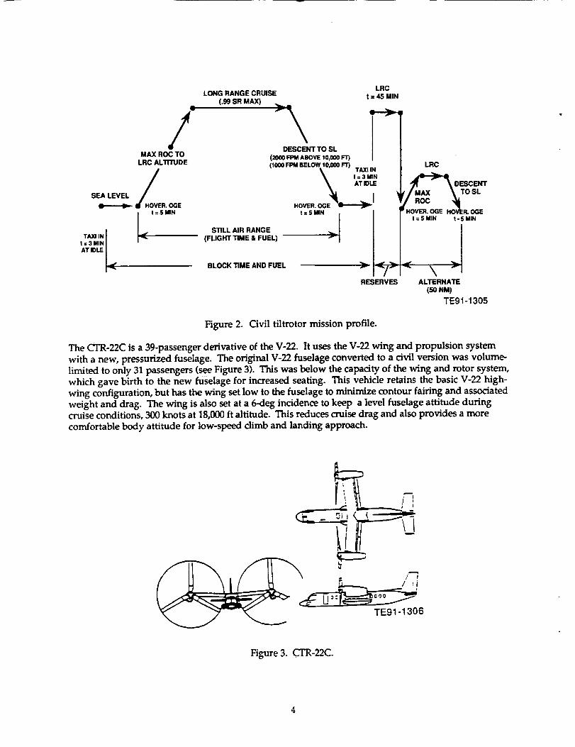
Figure 2. Civil tiltrotor mission profile.
The CTR-22C is a 39-passenger derivative of the V-22. It uses the V-22 wing and propulsion system
with a new, pressurized fuselage. The original V-22 fuselage converted to a civil version was volume-limited to only 31 passengers (see Figure 3). This was below the capacity of the wing and rotor system,which gave birth to the new fuselage for increased seating. This vehicle retains the basic V-22 high-
wing configuration, but has the wing set low to the fuselage to minimize contour fairing and associatedweight and drag. The wing is also set at a 6-deg incidence to keep a level fuselage attitude duringcruise conditions, 300 knots at 18,000 ft altitude. This reduces cruise drag and also provides a more
comfortable body attitude for low-speed climb and landing approach.
TE91-1306
Figure 3. CTR-22C.

TheV-22AllisonT406-AD-400 (Allison Gas Turbine Division of General Motors) engine was used as the
basis for power available and specific fuel consumption of the CTR-22C aircraft. The engine torquelimit is relaxed, being consistent with the assumption of a new, civil 30-second OEI power rating. Thedrive system ratings are the same as the V-22, however, it is considered that some redesign of the main
transmission input spur gears and housing may be reciuired. Fuel system design was based on a wet-wingapproach yielding capacity of 1423 gallons. The digital FBW flight control system, hydraulics andactuators were left identical to those in the V-22, including the nacelle tilt actuators.
3.2 EVALUATION CRITERIA
To determine the net benefit, if any, of each APC, a method of evaluation was developed. This methodneeded to be: consistent with current practices associated with the application; relevant to the concepts
being studied; and intelligible as a first-pass of quantifying net benefits. An approach was neededwhich would show all major impacts on the baseline model in a way that would allow for direct
comparisons.
For a commercial application the key issues are profit and federal regulations. Profit can be shown tobe impacted by the direct operating cost (DOC), a familiar term in the commercial arena. Federal regu-lations play an important role in areas of emissions, safety and noise. The future environmental con-cerns will continue to increase and commercial manufacturers will be forced to find new technologies to
meet stricter requirements. Hence, the development of all evaluation criteria for APCs evolved fromthese two very important elements. Boeing Helicopters' personnel were very instrumental in the devel-opment of the evaluation criteria including weighing specific values of DOC sensitivity.
After discussions with Allison and Boeing personnel, it was determined that the most obvious items of
concern related to DOC were the following:
• SFC--Engine model runs were completed to determine the delta Specific Fuel Consumption impacton the DOC.
• EW--An Engine Weight delta was approximated for the added hardware of concept implemen-tation.
• EACwThe impact of the technology on Engine Acquisition Cost was approximated based ondevelopment and hardware costs.
Impact on the baseline due to emissions were calculated where pertinent. Safety issues were consideredvia the scope of OEI/hard accel cases. Noise considerations were eventually eliminated as an evalua-tion criteria because of the difficulty in assessing the impact on the evaluated systems. Early in the
investigation it was found that an engine maintenance cost (EMC) impact study would easily consumethe entire present funding in itself, hence, qualifying statements concerning the subject are made accord-ingly. DOC sensitivities and listing of the other studied criteria are found in Table I.
3.3 MISSION PROFILE STUDY POINTS
To obtain worthwhile information while maintaining simplicity, it was deemed necessary to view themission from two select operation points key to the overall mission profile. The two points chosen were
a takeoff point and a maximum (typical) cruise point. All APCs were to be evaluated at both pointsassuming that the full range of benefit versus penalty would be approximated. Table II shows the mis-sion points and the pertinent parameters.
5

Table I.
Evaluation criteria.
. Direct operating cost sensitivities*ADOC/A Specific fuel consumptionADOC/AEngine weight
ADOC/A Engine acquisition cost
ADOC/AEngine maintenance costADOC/AEngine dimensions
= 2.75%/10.0%= 0.04%/10.0%
= 2.50%/10.0%
= 2.20%/10.0%= no effect
baseline SFC = 0.423
baseline engine weight = 1,991 lbbaseline gross A/C weight = 46,240 Ibbaseline cost = 3.4M/engine(25% of A/C cost of 13,455M)did not use
2. Emissions
3. Safety (OEI-conditions)
*For individual DOC sensitivities, see Figure 23.
Table II.
Mission profile study points.
Cm_se Takeoff
Shaft horsepower/engine
Temperature dayAltitudeMach number
3520ISA
20,000 ft303 knots
615059°FSea leveluw

4.0 CONTROLLABLE ADVANCED PROPULSION CONCEPTS
4.1 COMBUSTOR VARIABLE GEOMETRY CONCEPT FOR AIR-BREATHING ENGINES
Advanced air-breathing engine applications will demand more efficient and higher power enginescompared to the present designs. The operational range of future gas turbines is expected to be stretchedin both speed and altitude demands as civil/commercial transports cross over from advanced subsonic tosupersonic speeds at altitudes above 50,000 ft above sea level. The wide operational envelope, in turn,
demands high performance at all operating conditions. Combustion systems with fixed geometry(conventional designs) are therefore designed to operate efficiently in a limited flight envelope, there-fore becoming an undesirable design for future applications. As the combustion system operational
capabilities are stretched, the thermodynamic performance (at higher and/or lower operating condi-tion) is less than optimum, thereby losing efficiency and increasing the pollutant exhaust emissions.
The thermodynamic performance of the combustion section in a gas turbine engine depends on the propermixture of fuel and air. Consequently, inefficiencies caused by incomplete combustion and high temper-ature reactions can form carbon monoxide (CO), nitrogen oxides (NOx), unburned hydrocarbons (UHC),
and soot formation (smoke). These gas emissions are becoming an increasing concern in polluting theenvironment, therefore encouraging technology to produce gas turbines with more restrictive emission
requirements.
Therefore, an important design criteria in the development of advanced gas turbine designs consists ofoperating the combustion chamber at or near st oichiometry at all performance conditions to minimizethese inefficiencies. Unfortunately in fixed geometry combustors, at low operating conditions, operatingat low fuel/air ratios, CO and UHC production is high and NOx production is low, and the reverseoccurs at high operating conditions where the operating conditions have fuel/air ratios closer to thestoichiometric value. Therefore, a good combustor design achieves a good compromise to minimize all
emissions throughout the operating range.
A variable geometry combustion liner can be used to change the overall air distribution to the combus-tor, thereby varying the primary zone and dilution zone fuel/air ratios. With this variable geometryconcept (see Figure 4), the combustor airflow admitted to the front end is increased to enhance the mix-ture of air and fuel at the higher operating conditions to reduce smoke and lower the overall flametemperature to reduce NOx. Similarly, the variable geometry can be adjusted to permit less air in theprimary zone (front end) of the combustor at lower operating conditions to allow increased stability andreduce the production of CO and UHC by burning the fuel at a richer fuel/air mixture.
SPEI_)
T3
FIA 2
SPEED
POSITION REQUEST _ _ _CTUATOR
T ITE91-1287
Figure 4. Combustor variable geometry block diagram.

Thefuel/air ratioat theprimaryzoneisconsideredto be crucial in the production and consumption ofthe gas emissions. The fuel/air ratio (f/a) is significantly changed by selectively controlling theamount of air entering through the primary zone jet orifices. The critical design conditions are idle andmaximum power conditions since CO and UHC tend to be high at idle while NOx is higher at maximumpower due to the high temperature combustion interior environment. The emissions of the baseline ref-erence combustion system (T406) is acceptable at or near the maximum operating condition (takeoff);however, idle emissions could be significantly improved, especially for commercial/civil applicationswhere Environmental Protection Agency (EPA) operation cycles are applied.
In the T406 combustion system, the idle operating primary zone equivalence ratio (defined as the f/a forthe primary zone divided by the stoichiometric f/a) is 0.444. The equivalence ratio at stoichiometry is1.00. The CO and UHC emissions from a T406 engine operating at idle are significantly high, consider-
ing that the typical EPA landing-takeoff cycle demands an idle operation time of 26 minutes. The cur-rently proposed variable geometry combustor design applied to the T406 annular combustor can increasethe primary zone equivalence ratio to 0.576 if the primary zone jets are totally blocked. This wouldeffectively decrease the idle CO emission by 53% and reduce the UHC emission by 69% over those pro-duced by the baseline T406 current design. The predicted NOx emission indicated a 1% increase com-pared with the T406 value at idle. In addition, no significant change was produced in the smoke signa-ture compared to that of the T406 baseline. These values were obtained by using Allison-derivedempirical correlations based on extensive test data on the T406 engine. These empirical correlations arecomplex equations which depend on combustor volume, fraction of air to the primary zone, temperaturein the primary zone, inlet pressure, liner wall pressure drop, fuel spray droplet size, fuel droplet evapo-ration rate, stoichiometric temperature, fuel, and air properties.
The variable geometry would therefore change the current T406 design by blocking the primary zone jetstotally or partially to lower the emissions at the idle conditions. Similarly, the variable geometrywould revert back to the original T406 configuration to obtain the good emission signature of the currentT406 at or near maximum power.
The variable geometry control in the combustor is performed by varying the orifice area of the primaryand dilution zone holes located in the side wall of the combustion liner. The dilution zone holes are
simultaneously changed along with the primary zone holes to maintain equal pressure drop throughthe combustion liner since this significantly affects the pattern factor. The variable geometry hard-
ware design is shown in Figure 5. The hole size is effectively changed by sliding tabs over the hole,thereby increasing or decreasing the blockage area. The controls for the primary and dilution zoneholes are linked to a master control which allows the primary holes to reduce while the dilution zoneholes are increased and vice versa. The mechanical drive is provided by a digital stepping motor with
a position control. The correct position of the variable geometry at different operating conditions willbe determined by establishing a flame temperature curve in the primary zone of the combustion system.The flame temperature in the engine control feedback unit is determined using the measured compressordischarge temperature (T3), combustor fuel/air ratio (f/a), and gas generator rotor speed (Ng) as inputsto the ideal temperature rise relations for a specific fuel. The combustor airflow rate needed for theF/A will be calculated using the measured Ng using empirically determined compressor performancerelations. Therefore, the relation between the variable geometry (VG) position and Ng, F/A, and T3
will be processed by the computer logic which will actuate the stepping motor via a digital indexerdriver. The driver, in turn, sends the proper signal to the stepping motor using a position sensor as feed-back to indicate the location of the VG mechanism. Additional work is required to detail the concept ofthe mechanical control to actuate the blocker rings blocking the primary and dilution zone holes.
The weight of the variable geometry actuation mechanism is estimated to increase the baseline com-bustion liner weight by 8%, and an overall baseline engine weight increase of 1.40%, with all hardwareincluded. The cost of the variable geometry design has been estimated to increase the overall engineacquisition cost by 1.90%. The proposed components listing is given in Table III.

In sumn_ry, the variable geometry combustor design can significantly decrease the emission CO andUHC signatures of the baseline T406 combustion system with little change in the NOx emissions. This
is potentially advantageous for civil/commercial aircraft applications which, due to the increase inairport traffic, require long term operation at idle.
Table III.
Combustor variable geometry, components list.
UnitVolume Density Unit weight Total weight
_in.3 _3 "lb Ouanti_ -lb
Actuator 4.40 0.28 1.23 2 2.46Actuator hardware 1.50 2 3.00
Actuator plumbing 2.00 2 4.00
Torque rod 0.25 2 0.50Link 0.10 0.28 0.03 2 0.06Rocker arm 0.05 0.28 0.01 6 0.08
Outer forward ring 1.19 0.28 0.33 1 0.33Outer aft ring 1.48 0.28 0.41 1 0.41Inner forward ring 0.62 0.28 0.17 1 0.17Inner aft ring 0.25 0.28 0.07 1 0.07Outer forward retainer 0.48 0.28 0.13 4 0.54Outer aft retainer 0.48 0.28 0.13 4 0.54Inner forward retainer 0.48 0.28 0.13 4 0.54Inner aft retainer 0.48 0.28 0.13 4 0.54
0.15 4 0.60Fasteners
Total 13.85

i i 77. 18 ---
60.01 ---
i ' 9Z
a)
I[II
II
" It
0 ''
'ii;i I
TE91-1302
Figure 5. Combustor variable geometry.
10
4.2 COMPRESSOR VARIABLE GEOMETRY
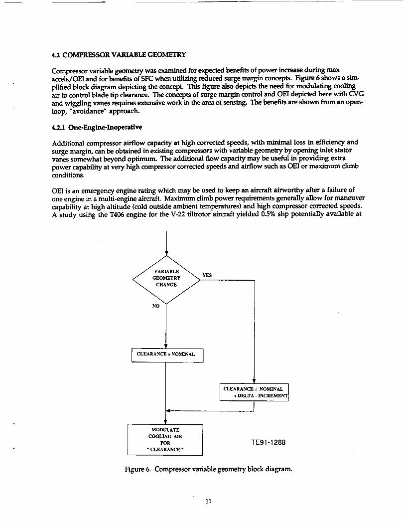
Compressor variable geometry was examined for expected benefits of power increase during maxaccels/OEI and for benefits of SFC when utilizing reduced surge margin concepts. Figure 6 shows a sim-
plified block diagram depicting the concept. This figure also depicts the need for modulating coolingair to control blade tip clearance. The concepts of surge margin control and OEI depicted here with CVG
and wiggling vanes requires extensive work in the area of sensing. The benefits are shown from an open-loop, "avoidance" approach.
4.2.1 One-Engine-Inoperative
Additional compressor airflow capacity at high corrected speeds, with minimal loss in efficiency andsurge margin, can be obtained in existing compressors with variable geometry by opening inlet statorvanes somewhat beyond optimum. The additional flow capacity may be useful in providing extrapower capability at very high compressor corrected speeds and airflow such as OEI or maximum climbconditions.
OEI is an emergency engine rating which may be used to keep an aircraft airworthy after a failure ofone engine in a multi-engine aircraft. Maximum climb power requirements generally allow for maneuvercapability at high altitude (cold outside ambient temperatures) and high compressor corrected speeds.A study using the T406 engine for the V-22 tiltrotor aircraft yielded 0.5% shp potentially available at
NO
YES
P
I CLEARANCE = NOMINAL I
r
MODULATE
COOLING AIR
FOR
"CLEARANCE"
CLEARANCE = NOMINAL
+ DELTA - INCREMENT
TE91-1288
Figure 6. Compressor variable geometry block diagram.
11

OEIand1.6% at the maximum climb rating condition. As noted, this benefit is only available at high
compressor corrected speed.
These potential improve_ts in OEI/max climb do not lend themselves to any SIC benefit but do,however, address serious safety and power requirements.
4.2.2 Reduced Su_e_
Compressor variable geometry can also show performance benefits by reducing design surge margin.Compressors are normally designed with at least 15% surge margin. This surge margin covers a numberof effects which work to either move the surge line closer to the operating line (Reynolds number, dis-
tortion, compressor-compressor variations, variable vane schedule inaccuracies) or the operating linecloser to the surge line (engine deterioration, acceleration requirements). Normally these effects arecombined in a worse-case scenario to define a minimum surge margin requirement and a cushion as a
safety factor is left over. A performance benefit can be achieved if we assume that we can develop acombination of stall inhibitor (wiggly vanes, acoustic feedback) and detection/recovery (fast sensors
with a fast-feedback loop to fuel flow and or compressor vane schedules or bleeds) systems which wouldallow design of a compressor operating point closer to its surge line.
A study using the T406 engine for the V-22 tiltrotor aircraft yields the following potential performanceimprovement assuming a 5% reduction in required surge margin, i.e., elimination of the cushionnormally allowed for in doing a surge margin audit (see Figure 7). By reducing the surge margin 5% it isseen that the corresponding pressure delta yields a 0.7% decrease in SIC. If a compressor can be
"taught" to live with 5% surge margin, or if the effective surge line can be moved, two or three timesthis effect can be achieved.
With the increased ability to manipulate the pressure characteristics within the compressor, addi-tional analysis was performed to determine the benefit potential of redesign. It was estimated that ifa 10% surge margin allowance could be won using compressor variable geometry, one complete stage ofthe compressor could be eliminated. This would yield a weight delta of 0.81%. Redesign, however,would require further detailed analysis. This does, however, demonstrate the SFC/weight trade-off.
24
2O
16
RC 12
0
14
OP. LINE w/10.6% S.M.
SURGE J _-/__
\ \' ' 'z
8!0 9O.O
80.0
! ! t == I I / ! 1 I / I I I I
16 18 20 22 24 26 28 30 32 34 36 38 40 42
FLOW TE91-1464
Figure 7. CVG benefits for reduced surge margin.
12

Currently,theT406usescompressorvariablegeometry.TableIV showsthelistofhardwareusedforthe system with corresponding weights.
4.3 WIGGLING VANES AND SURGE CONTROL
Axial compressors are subject to two distinct aerodynamic instabilities, rotating stall and surge, whichcan severely limit compressor performance. Rotating stall is characterized by a wave travelling aboutthe circumference of the machine, surge by a basically one-dimensional fluctuation in mass flow
through the machine. Whether these phenomena are viewed as distinct (rotating stall is local to theblade rows and dependent only on the compressor, while surge involves the entire pumping system) or asrelated (both are natural modes of the compression system with surge corresponding to the zero order),
they generally cannot be tolerated during compressor operation. Both rotating stall and surge reduce
the pressure rise in the machine, cause rapid heating of the blades, and can induce severe mechanicaldistress.
The traditional approach to the problem of compressor flow field instabilities has been to incorporatevarious features in the aerodynamic design of the compressor to increase the stable operating range.Balanced stage loading and casing treatment are examples of design features that fall into this cate-gory. More recently, techniques have been developed that are based on moving the operating pointclose to the surge line when surge does not threaten, and then quickly increasing the margin whenrequired, either in open or closed loop manner. The open loop techniques are based on observation, sup-ported by many years of experience, that compressor stability is strongly influenced by inlet distortionsand by pressure transients, such as is caused by aircraft angle of attack and yaw angle. Thus, significantgains have been realized by coupling the aircraft flight control and engine fuel control so that theengine operating point is continually adjusted to yield the minimum stall margin required at eachinstantaneous flight condition (see subsection 4.7).
Studies conducted at MIT regarding the onset of surge have revealed a small perturbation that appar-ently grows and ultimately results in the large scale surge that is damaging. The concept and subsequent
Table IV.
CVG components list.
Arm and ball
Actuator ringArm and ball
Actuator ringArm and ball
Actuator ringArm and ball
Actuator (approximate wet weight)Actuator mounting hardware (approximate)Actuator ring and button assembly-IGV
assembly-IGVand button assembly-stage 1
assembly--stage 1and button assembly--stage 2assembly-stage 2and button assembly-stage 3assembly--stage 3
Actuator ring and button assembly--stage 4Arm and ball assembly-stage 4Actuator ring and button assembly-stage 5Arm and ball assembly--stage 5Miscellaneous associated hardware
Total weight
Weight--lb
4.1000O30OO2.09300.50401.83201.0400
1.83001.08001.80801.08001.80801.08001.80801.0800
23.587
13

experiments performed at MIT work on the basis that active stabilization can be brought about by thepassage of a convected field of vortices shed from upstream oscillating vanes. The vortices weakly dis-turb the downstream flow and prevent the development of a stall. This can be used to move the operat-ing line up and provide improved gas turbine performance. The concept is depicted in simple block dia-gram form in Figure 8.
If, as the theory implies, rotating stall can be viewed as the mature form of the rotating disturbance,damping of the waves would prevent rotating stall from developing, thus moving the point of instabil-ity onset as shown in Figure 9. It was proposed that the compressor stability could be augmented by
SPEED
FREQUENCY
COMMAND
amplitude = 0.25
TRUE IF
PLA- dot > PLA- dot limit
(infers hard accel)
im
0
VANE ACTUATOR COMMAND
Figure 8. "Wiggling vanes" block diagram.
Region / Surge LineStabilized
With ControlWith Active
Control // / Actively Stabilized\ // __/ Operating Point
\ ,z.e,/.:.
:% " ,-.,._ Performance
//. _lmpro_ement" _ Operatin Point
< _ Vithout_'°ntr°l
Surge Line _ Constant
Without Control Speed Line
CORRECTED A. C.
TE91-1289
Mass Flow TE91-1290
Figure 9. "Wiggling vanes" performance benefits.
14

creatingatravellingdisturbancewithphaseandamplitudebasedonreal time measurement of the
incipient instability waves. The basic concept is to measure the wave pattern in a compressor andgenerate a circumferentially propagating disturbance based on those measurements so as to damp thegrowth of the naturally occurring waves. Implementation of individual vanes in an upstream blade roware "wiggled" to create the travelling wave velocity disturbance (see Figure 10).
The current studies and experiments done by MIT have shown what type of benefit can be achievedwith this concept. From this information approximations have been made for the T406 of the referenceaircraft V-22. The 3"406 currently incorporates compressor variable geometry as shown in Figure 10. Theaddition of actuation hardware could be implemented at one stage of vanes to provide a +10 deg ampli-tude at 200-300 hertz frequency. This would result in SFC benefit, same as found in section 4.2. Thehardware would result in a cost delta of +0.58% and a weight delta of +0.6%, based on a two actuator
system (see Figure 11).
This concept requires a considerable amount of further research but shows a lot of promise. Studies onthe current T406 compressor would be required to gather information for appropriate modeling. Also,the existing compressor variable geometry hardware would need to be assessed for Implementation dif-ficulties or modifications. The limitations of the overall system would have to be analyzed to deter-mine what level of benefit could actually be obtained. The values herein are of a rough order of magni-tude and rely solely on the studies done with MIT and the expected cost/weight analysis of
implementation.
4.4TURBINEVARIABLEGEOMETRY
Variable geometry can be used to enhance the performance of gas turbine engines. Turbine variablegeometry can be useful in improving both steady-state and transient performance. In the transientmode, variable geometry can be used in place of an acceleration bleed valve in order to improve acceler-ation times while maintaining adequate surge margin. For the study at hand, turbine variable geome-
try was examined for benefits of SFC at cruise and potential horsepower increase at the one-engine-inoperative (OEI) engine sizing point (see Figure 12a-c). The commercial tiltrotor application pre-cludes studying the positive impact of turbine variable geometry on accel time. In general, propellerpitch change mechanisms operate much slower than the engine, i.e., the engine can ramp up or down inpower much faster than the propeller can absorb it. Thus, this application is not impacted by faster
Inlet Guide 0Vanes
I '2_jI"
D
CO "_
L ,ira..
C x ....m
iww
B
w
IVelocity at
Compressor Inlet(Sense This)
/CirculationChanges
(Move This)
0
Velocity FieldDue to
Blade Motion
'-": ":: i,_ I
•. ,.--t- CompressorI
=X
TE91-1291
Figure 10. Circumferential wave disturbance.
15

TE91-1307
Figure 11. "Wiggling vanes" actuator location.
accel times as a combat helicopter mission would be. Data presented in the Phase I report (reL 1) forthe LH Comanche T800 engine is still applicable.
To determine the SFC benefit potential for cruise a simulation was performed for the T406 engine. Inthis implementation the assumption was made that the effect of varying the turbine vane angles wouldsolely be a reduction in turbine flow capacity. The results of the simulation are given in plot form inFigures 13 and 14. The study shows the relationship between two pertinent parameters, namely horse-power and SFC. The turbine variable geometry was allowed to adjust flow +10% in both the gas genera-tor and the power turbine. By reducing gas generator flow by 10% and maintaining nominal flow in thepower turbine it was found that an improvement to SFC of 1.3% was achieved. At these conditions a
negligible loss in horsepower was experienced.
The other major benefit found in turbine variable geometry was in increased safety. When conditionsarise that would require maximum output of the engine, SFC is no longer a concern. All SFC can be sacri-
riced to secure the safety of the commercial aircraft passengers. Any occasion for hard accel require-ments or even the worse case scenario of one-engine-inoperative (OEI) demands the engine to providehorsepower to its full capacity.
For takeoff, using the data as portrayed in Figure 14, an increase in power turbine flow of +5% yields anincrease of 275 hp while +10% flow yields near 400 hp. Again, the gas generator turbine flow was heldat nominal.
To determine an impact on weight a list of essential hardware was compiled with individual compo-nent weights. The data were based on earlier experience Allison had with turbine variable geometryon the GMA 800 engine program. A scale factor was applied which yielded approximate hardware
weights. The information is depicted in Table V. The total engine weight delta could then be found tobe 3.3%. However, the option of redesign must be examined to explore the full benefit potential.
16

SHP
WFT
N-dot
4
O
AND DETERMINE
SFC SENSITIVITY
TO VG SETTING
NO
MAINTAIN
OPTIMUMVG
Ia)
NO
COPJP.ECrgD
NO
b)
AREA MAX TURBINE
r- ACTUATOR
EMERGENCY REQUT.ST
POWER
_QuF_r(PLA MAX)
SPEED
Figure 12.
TIT MAX
c) TIT
Turbine variable geometry block diagram.
SELECT
LOW
DELTA
FUEL HOW
TE91-1292
17

o. 0.3gOO-r-
0_. 0.3850-E
t"-
8
_ 0.38O0-
"Boe,J
0.3750-
'_,-....... !_l_-+lu
...... _ggt :
\
I
0.4150-
0.4100-o..J::
J_
0.4050-
E
_ 0.4000-o
_ 0.3950-°_
5800
• I i i '
6000 6200 6400 6600 6800 7000Corrected shaft horsepower-shp
Figure 13. Turbine variable geometry potential at cruise.
7200 7400
TE91-1293
0.3900-
0.3850-
,.r
",,_-_.'_ ._ _ "_?'_'
.....
!
"--'-'/0z
5600 5800 6000
Figure 14.
%• I
i I i l _ i "
%
i I
--J---- ......
i i i
\
/]
l l "l ( i i
6200 6400 6600 6800 7000 7200 7400
Corrected shaft horsepower-shp TE91-1294
Turbine variable geometry potential at takeoff.
18

TableV.Turbine variable geometry, components list.
GMA 800 T406
Vane quantityInner stem diameterOuter stem diameter
Actuator ring mean radiusCompressor corrected airflow
GMA 8O0
weight-to
30 42
0.625 0.3750.5 0.2513.2 11.165 37.7
,C_alef'_orsInner Outer Actuator
Vane stem stem ring
quantity Oiameter _liameter Oiameter
outer buttonInner button
outer piston ringouter spindleInner spindleouter endwallInner endwall
Outer bearingInner bearingInner snap ringInner bearing nutOuter bearing spacerInner bearing shimOuter bearing seal ringInner bearing seal ringInner support structure
Strip seals
3.256 1.4 -- 0.1252.646 1.4 0.216 --0.344 1.4 -- 0.1254.389 1.4 00 0.125
3.293 1.4 0.216 --8.684 1.4 -- 0.1258.322 1.4 0.216 --2.850 1.4 -- 0.1252.850 1.4 0.216 --0.144 1.4 0.216 --1.108 1.4 0.216 --0.474 1.4 -- 0.1250.029 1.4 0.216 --2.318 1.4 -- 0.1250.708 1.4 0.216 --6.892 1.4 0.216 --0.426 1.4 -- 0.125
Subtotal 48.733
Actuation system
Compressorcorrected
airflgw
f.
T406
weight-4b
0.570.800.060.771.001.522.520.500.860.040.340.080.010.410.212.08O.07
11.84
Outer spindle hardware 4.500 1.4 -- 0.125 .... 0.79Splined sleeve 0.130 1.4 -- 0.125 .... 0.02Lever arm 7.200 1.4 ...... 0.58 5.85
Sync ring and hardware 10.460 ...... 0.841 -- 8.80Bearing lock nut 1.450 1.4 -- 0.125 .... 0.25Insert spacer 2.400 1.4 -- 0.125 .... 0.42Two actuators 37.440 ........ 0.58 21.72Air motor 22.700 ........ 0.58 13.17Flex air motor drives 2.000 ........ 0.58 1.16Air motor brackets 1.000 ........ 0.58 0.58
Inlet and exhaust piping 2.000 ........ 0.58 1.16
Subtotal 91.280
Total 140.013
53.91
65.75
19

AssumingOEIconditionsandsizeof theengine,asmallerdiameterturbinecould be designed, withvariable geometry, to provide the required horsepower. For example, Figure 14 showed an increase of400 hp from an increase of +10% in flow. This translates to a 5.8% increase of shaft horsepower. TheT406 characteristics are such that a one-to-one (1:1) relationship exists between hp and weight, hence a
5.8% weight benefit is seen. This results in a net weight delta of-2.5%. For any redesign study,considerable further analysis is required.
A cost factor was then processed by establishing a nonrecurring development cost and the cost of thehardware. The engine acquisition cost delta was found to be 7.3%. Some impact on maintenance wouldcertainly be seen but the study is beyond the scope of this program. As is the case with most of the AI_sfurther, more detailed studies are required to determine the full range of effects of adding turbine vari-able geometry. The hardware concept is shown in Figure 15.
4.5 PATTERN FACTOR CONTROL USING AN ACTIVE FUEL CONTROL SYSTEM
Advanced air-breathing engine applications will demand more efficient and longer lasting gas turbineengines. Higher engine efficiencies are obtained by selectively increasing the engine pressure ratio andincreasing the burner outlet temperature. Allison presently has two ongoing programs dealing with thehot section design of an advanced T406 (straight annular) and TS00 (reverse flow annular) combustors
with operating conditions demanding burner outlet temperatures in the 3000°F range. The burner outlettemperature distribution in engines with BOTs above 3000°F becomes extremely critical in affecting tur-bine vane and blade component lifetime and therefore affecting overall engine maintainability. There-fore, parameters such as pattern factor and radial temperature profile become an even more critical ascriteria in the design of the engine hot section.
Allison recognizes that the burner pattern factor (Tmax - Tav) divided by the temperature rise of thecombustor (Tav - T3) is affected by several parameters including combustor primary zone mixing, dilu-tion zone air distribution, and fuel nozzle performance. In annular combustors with several fuel nozzles,the fuel distribution around the combustor is a major contributor to the localized temperature variations
which, in turn, produce changes in the pattern factor. The flow variation allowed in the T406 modelfuel injectors is +5% at any operating condition. This variation alone can produce substantial tempera-ture changes within the combustor. A 5% fuel flow rate increase in one nozzle can produce a 55°Fincrease in Tmax, thereby significantly affecting the turbine blades and vanes located downstream ofthe malfunctioning fuel injector. Fuel maldistribution is also the result of nozzle flow rate variationsthat could be caused by internal coking and general fuel nozzle degradation. In addition to the fuel noz-zle flow variation, one has to contend with the airflow nonuniformities around the combustor liner due
to many reasons, e.g., manufacturer ring variabilities. Given the operational requirements of the T406engine, there is a need for a "smart" fuel system able to correct itself for fuel injector performance normalspec variation and temporal degradation. Allison is presently considering the use of an "active" fuelcontrol system with a full feedback control.
An "active" fuel control system concept is shown in Figure 16. The fuel flow rate in each of the annularcombustor's 16 fuel nozzles is measured and controlled by a "black box" controller, which drives a motor-ized fuel flow rate valve. The black box, in turn, is controlled by a commanding unit with sophisticatedsoftware which senses the output from the temperatures measured near the burner outlet plane. Much
work is needed to determine the sensing technology required to implement this concept. Therefore, thefuel control system is designed to be a closed loop feedback system where the sensed aberrant tempera-ture readings are fed to the control unit which then selects the proper combustor fuel manifold distribu-tion necessary to eliminate that aberration. Therefore, there is a high certainty that a decrease orincrease in temperature at the burner outlet plane at a certain location around the combustor correlateswith the fuel nozzle at that same circumferential location. Small phase shifts, however, are expected
due to the flow nature in typical annular combustors combined with the fact that some residual swirl isleft in the flow after exiting the compressor exit guide vanes.
2O

77, lB
= 60.01
:i7
22.92
b) - close-up TE91-1301
Figure 15. Turbine variable geometry hardware.
21

FLOW SENSINGORIFICE AND TRANSDUCERS
o FUEL FLOW RATE CONTROL INOF 16 FUEL NOZZLES
o FUEL STAGING CAPABILITY
EACH
DIRECT DRIVHOTOR
METERING SPOOL
VALVECONTROL
FUELINLET
BLACK PILOT CONTROL ANDBOX FEEDBACK
FLOWFEEDBACK
TEHP"EEDBACK
Hgum 16.
TURBINE
High stability combustor actively controlled fuel injector.
TE91-1465
The fuel flow rate control box for each nozzle essentially contains a digital stepping motor with posi-tion feedback and a fuel flow rate valve. The digital stepping motor has both the required torque and
accuracy which are essential to make the appropriate vernier fuel flow rate variations on the order of+1%. The position feedback in the stepping motor allows the commanding unit to sense the flow rate to
provide a double feedback control loop along with the sensed burner outlet temperatures. The steppingmotor will be chosen to operate in high temperature environments and will be capable of being totallysubmersed in the fuel for additional cooling purposes since the flow control "black box" will be located
as close as possible to the fuel nozzle. Extra precautions will also be taken to select a stepping motorwith the appropriate safeguards against fire hazards.
The master control unit incorporates indexing drivers (for all 16 stepping motors) and the logic hard-ware which supports the necessary software capable of processing the inputs from the temperature sens-
ing devices and commanding the outputs to each individual nozzle flow rate control box. The conceptdemonstration will first be accomplished in a full scale annular combustion rig capable of simulatingthe appropriate inlet conditions of pressure, temperature, air, and fuel flow rates necessary to make thecombustion system work as if it were installed in an engine. The combustor inlet and outlet conditionsand combustion system performance parameters can be more accurately controlled and studied in a com-bustion rig compared to an engine test where extensive instrumentation is limited due to the space con-straints. The temperature sensing devices in a combustor rig test can be provided by a rotating rake with
radially located thermocouple probes across the annulus. The rotating probe should be capable ofobtaining a full 360 deg temperature survey. Five temperature probes are mounted on the rotatingthermocouple rakes at different radial locations to measure the temperature variations in the radialdirection across the combustor outlet plane. For an engine demonstrator, however, special stationary
(high temperature) long endurance thermocouples will be located in the burner outlet plane downstreamof each of the 16 fuel injectors instead of a rotating temperature rake. Optical fiber optic temperature
sensing devices will be installed in engine designs where the burner outlet temperature exceeds 2500°F
22
sincetheconventionalthermocouplecomponentlife isseverelylimited in hightemperatureenvironments.
Theestimatedpatternfactorreductionusingthe active fuel control system can be more than 36% from0.22 to 0.14. This change in pattern factor implies that the maximum temperature value at the burner
outlet plane could be reduced by at least 100°F. This decrease in Tmax can potentially lead to a turbinecomponent life increase of over 100% compared to the T406 turbine.
Therefore, the maintenance cycle can be significantlyimproved with the use of an "active" fuel control
system. An accurate assessment of the benefits of the "active" fuel control system is presently difficultdue to the lack of test data available. Allison is presently working on a test demonstration using a
semiactive fuel control system where the test operator will provide the closed-loop feedback betweenthe sensed temperatures at the burner outlet plane and the actual fuel control in each of the 16 nozzles
in a T406 type combustor. This demonstration test, however, is only an initial step since further investi-gation is required to maximize the weight/performance trade-off. The present system is estimated toincrease the weight of the engine by 2%, but due to material optimization, this estimate can be reducedto about 1% or less.
The present acquisition cost of the active fuel control system which includes a digital stepping motor,fuel valve, indexer driver for the stepping motor, power supply, temperature sensing device, software
providing the active control between temperature and fuel flow rate, and associated electronic linkagesbetween the center command has been estimated to be about $3000 for each fuel injector of which thereare 16 in a T406 combustion liner. This cost amounts to 2.8% of the total engine acquisition cost. The
production cost can be estimated to be significantly lower due to the quantity required per engine andthe amount of engines manufactured.
In summary, this innovative fuel control system is able to correct the fuel delivery distribution, therebydecreasing the burner outlet pattern factor and decreasing the overall maximum temperature which
significantly impacts the turbine component lifetime. The active fuel control system is also an effectivedesign able to compensate for spec and temporal fuel injector flow rate changes thereby increasing theoverhaul mean time between repair (MTBR) maintenance record of the present T406 baseline design.
4.6 ACTIVE CONTROL OF CHARGEABLE COOLING AIR
Cooling air requirements have a direct impact on engine performance. Typically, these levels are set bymaximum temperature takeoff conditions and results in overcooling at other off-design conditions. Thisover-cooling is a significant performance loss. Having the capability of modulating this air to reducedlevels at off-design conditions represents a potential performance payoff. Previously, the potential
payoff for a modem flit-rotor aircraft was estimated, but did not examine the details of the system.This work effort takes a next-step look at how this can be accomplished conceptually, and re-examinesthe benefits.
A T406-AD-400 engine with 6.7% chargeable cooling air was used as the baseline. Two cooling air feed
circuits on the high pressure turbine were chosen for investigation because of the high potential payoff.A 20K, 0.5 Mn altitude cruise condition at 1870°F rotor inlet temperature was selected for evaluation.
Figure 17 shows the details of these controllable circuits. The second stage vane, the first circuit ana-lyzed, which was previously fed from the cavity between the inner and outer case, is now fed from avalve which extracts air from the outer combustor cavity. At the cruise condition, the gas path tem-
peratures are lower than the allowable metal temperatures resulting in the ability to completely shutthis air supply off. This results in a 0.7% savings in chargeable cooling air at this flight condition.
The second circuit examined is a much more complex system to evaluate. Cooling air exiting the
preswirler supplies air to the first-stage blade and first- and second-stage wheel cavities. Heat trans-fer analysis of the rotor system at the altitude operating condition indicates that the blade requires no
23

a) - before b) - after TE91-1296
Figure 17. Active cooling air control.
cooling air and the wheel cavities can be reduced significantly. Analysis of the internal flow systemindicates that the current T406 configuration would require an additional sealing change in addition to
adding the valving system. The preswirler aft labyrinth seal would have to be replaced by an essen-tially zero leakage seal, such as a film-riding face seal. This would be required to prevent starvationof the first-stage wheel forward cavity. Figure 17 depicts the modified cooling air circuit, indicating
that the preswirler flow can be reduced by 1.5%. Figure 18 shows the overall concept hardware
implementation.
Examination of the baseline 3"406 engine suggests that 22.% in cooling air can be modulated for an alti-
tude cruise condition, resulting in a 1.3% decrease in engine SFC while maintaining life. While the
ability to modulate the cooling air at this condition exists, there are additional implications that mustbe considered. Modification to the cooling circuit can alter blade tip clearances, interstage seal clear-
ances, and blade/vane overlap gaps, all of which can impact performance and cooling air requirement s .A detailed structural analysis would be required to assess the implications and trade-offs. Advanced
engines in this class operating at 2600-3000°F would probably show an even higher SFC impact sincebase chargeable cooling flows are higher.
The system would be active only in the cruise condition where performance loss, due to design, is signifi-cant. Hence, performance is not affected at takeoff, as demonstrated by the simplified block diagram
found in Figure 19.
24

a)
i
L_
7777r----r f.... 71 i-T1777
b) - close-up
7-
TE91-1303
Figure 18. Active cooling air control hardware concept.
25

COOLING
AIR TO
DESIRED
LEVEL
INCREASE
COOLING
AIR TO
NOMINAL
TE91-1297
Figure 19. Active cooling control block diagram.
The implementation concept, yielding the performance benefits listed above, requires hardware for the
cooling air tubes and for the seal at the preswirler. Some nonrecurring development and testing costs
would be involved, but when considering the costs of the hardware per engine (primary) and the impact
on maintenance costs (secondary), these can be considered negligible. The total cost impact for acquisi-tion was calculated to be approximately 1.0%.
The hardware described will also have a weight impact. Table VI depicts the concept weightapproximations. The total impact on engine weight is 0.8%.
Table VI.
Weight of active cooling concept hardware implem_ntatiqn.
Unit Total
weight-lb Ouantity weight--lb
Control valve
Control valve hardware
Turbine vane cooling air tubesTurbine vane outer hardware
Blade cooling air tubes
Film riding face seal
1.20 4 4.80
0.75 4 3.00
0.24 4 0.97
0.35 14 4.90
0.22 8 1.75
1.50 116.92
26

4.7 PERFORMANCE SEEKING CONTROL
The application of performance seeking control (PSC) to the Civil Tiltrotor is approached in this studyfrom two levels. The first is at the level of the propulsion system alone and the second includes the air-
frame in the optimization analysis. Before discussing these concepts a short description of the V-22system is in order. The current engine/rotor control system for the V-22 tiltrotor is shown in Figure 20.
The Allison Full Authority Digital Electronic Controls (FADECs) and engines are shown as part of an
overall thrust power management system (TPMS) which governs both the engine and rotor system toprovide height/rate-of-climb control in the VTOL mode and airspeed control in the airplane mode(ref. 1). Throttle inputs are analogous to collective control in a helicopter and throttle control in anairplane. The TPMS is supplied by the airframer Beg-Boeing. In the TPMS system the inputs to theTPMS engine control are the pilot commands, shown as thrust control lever ('rCL) and engine conditionlever (ECL). Mast angle (engine nacelle angle) is controlled directly by the pilot usinga separate leverand is set according to his feel for what works best. The TPMS provides for throttle (TCL) quickening to
improve handling qualities, engine starting and throttle response shaping based on ECL command, andOEI compensation. The TPMS then produces a left and right power demand signal (PDS) to each
FADEC system of the two T406 engines.
The TPMS rotor speed control provides conversion to collective pitch control of the propellers duringtransition from airplane to helicopter mode and it provides feed forward pitch control for improvedairplane mode throttle response. Another feature of the TPMS is a torque command limiting system(TCLS) which prevents overstressing the V-22 transmission and provides for a more linear torque versus
TCL position function.
The new propulsion control system addressed here involves the further integration of the TPMS and theengine FADECs into one integrated multivariable control system (representing Level 1) and the furtherintegration still with the flight control system (Level 2). The Level 1"approach is shown in Figure 21and represents the total propulsion system control (engines plus rotors) control as a MIMO system ratherthan the current multiple independent SISO systems currently employed on the V-22. The use of multi-variable control is the natural progression that would be necessary to take advantage of the advancedcontrol concepts being investigated in this program and to enhance the tiltrotor propulsion system in
general.
The current T406 control, however, could still take advantage of an adaptive performance seeking con-
trol through trim inputs to its current fuel flow and compressor variable geometry commands. For thesake of clarity the rotor/propeller control signals currently generated by the TPMS are shown as adashed line which themselves may be included in the aircraft PSC system. In this configuration the
ENGINE #1 _lbTCL .
TPMS I DRIVEENGINE SYSTEM
CONTROL
_ ENGINE #2 Q_
RPM L
ROTOR
IRPM R
CONTROL /
Figure 20. Simplified engine/rotor control block diagram.
TE
LEFTROTOR
0C
RIGHTROTOR
tl -1298
27

IIIII
o_
o_
a_
0
28

pilot TCL, ECL and any outer-loop commands are fed into the propulsion system schedules. The outer-loop commands would consist of mast angle (beta), flight condition (stick and pedal commands, cruise,take-off, landing, OEI), and air-data computer (angle of attack, side-slip angle) outputs. The propul-sion system schedules then convert these commands to desired operating conditions in terms of the
following:
• NG---gas generator speed• P3i--compressor pressure at the "i"th stage• BC--burner condition (emissions)
• PF--pattern factor• TMT--turbine metal temperature
and rotor/propeller operating conditions (not shown):
• N-P---power turbine speed• Q--rotor torque• THETA--propeller pitch angle
These parameters cover the normal control loop (engine speed) and the variables of interest in this pro-gram with respect to advanced control modes (i.e., stall/surge control (P3i); turbine variable geometry
for increased power (NG); emissions (BC); pattern factor (PF), and active cooling control (TMT)).Maneuver predictions are provided from the flight condition data. Neglecting the PSC input biases forthe moment, these command parameters are then compared with the actual engine operating conditionsbased on processed sensor information, and the errors are then fed into the engine MIMO control to per-form actuation of the following:
• CVG--compressor variable geometry angle• TVG---turbine variable geometry angle• WF--fuel flow
• BVG--- burner variable geometry position (combustor can)• BPVGi--burner pattern variable geometry ("i"th fuel nozzle flow)
• BLD--turbine cooling flow bleed
The block diagram also shows additional engine parameters being fed back into the control for protec-tion logic which would include power turbine speed, engine torque and fuel flow limits. The form of theMIMO control is not important for this discussion but a concept used in the past by Allison is the "KQ-multivariable control" concept shown in Figure 22 in conjunction with a model-following regulator forfeed forward control and improved performance and command following (ref. 2). This is an easily
implementable control which is designed based on the desired response matrix. Allison has recentlybegun to investigate nonlinear control concepts such as neural nets fuzzy logic which may be of use forthe Civil Tiltrotor.
The PSC system is shown implemented as an adaptive trim method essentially the same as that cur-rently in the development and validation process on the NASA F-15 HIDEC aircraft (ref. 3) and as pro-
posed for the High Speed Civil Transport (ref. 4). The actual engine performance is compared with anideal mathematical model to update the model which is then used in the optimization logic (using amodel rather than perturbing the actual aircraft and engine removes the error associated with sensornoise and response uncertainties). The optimization logic then seeks to optimize the parameter ofchoice whether it is specific fuel consumption, thrust, life or other parameter affecting direct operatingcost (DOC). This technique should be capable of improving each of these parameters independently
and possibly more than one at a time depending on how sophisticated the performance index and theoptimization algorithm. Ultimately, the greatest payoff will be obtained by including both the
29

o _S
i
_qo
3O

advanced propulsion controls concepts with the airframe in the PSC problem as shown in Figure 22.This is the second level of PSC which is discussed next.
In this treatment the Design Methods in Integrated Control Systems (DMICS) program (ref. 5) structure
is shown with the PSC system providing trim inputs to the function level subsystem commands and eachinner loop control. The PSC loop is closed around these subsystems and the airframe to perform opti-mization of not only the engine performance according to external inputs but also to drive the inputs tothe engine by influencing the flight conditions and to improve aircraft system performance. The exter-nal inputs influencing engine performance are inlet conditions, propeller torque requirements, and throt-tle commands. These external inputs are affected by airspeed, angle of attack, mast angle, ambienttemperature and pressure. The last two are essentially uncontrolled parameters whereas the first threeare coupled to the flight control. That is to say that the airspeed, angle of attack and mast angle areinterrelated with the airframe flight control surface deflections. This is where the PSC might gain
additional performance enhancements through the optimization of parameters such as specific fuel con-sumption by "setting up" the aircraft in a low drag low inlet distortion flight condition. The optimiza-tion logic would determine the "cleanest" profile for the desired airspeed through the best balance ofengine thrust angle, thrust magnitude and elevator angle while reducing inlet distortion for improved
engine power.
4.7.1 Optimization Process
As stated, the performance seeking controller would employ an engine simulation which is continuallyupdated to match the operating characteristics of the actual engine. The effects of each advancedengine control concept would be included in this model. The compact engine model (CEM) used in thisprocess must necessarily be very accurate otherwise the PSC will provide poor performance and will notbe able to adapt to aging engines or properly represent engine operation. The CEM would consist of apiecewise-linear steady state variable model (SSVM) and a portion devoted to modeling those nonlin-ear effects which are not accurately represented by the linear models. Kalman filtering would be used
to estimate component deviations representing off-nominal performance (ref. 6). These componentdeviations would then be added into the model to force a match. For the T406 derivative it is expected
that there would be low and high spool efficiency adders, and a compressor airflow adder. Thistechnique was proven to result in accuracies within +2% for the HIDEC F-15 when compared to anonlinear aero/thermodynamic engine model (ref. 7), used as the "truth model," and was considered
sufficient for PSC purposes.
The PSC follow-on to the HIDEC program did not incorporate the flight control surfaces into the PSC
system but focused on adjusting the inlet, engine variable geometry and nozzle according to predictedand actual angle-of-attack and sideslip angle. The system discussed for the Civil Tiltrotor would alsoinclude maneuver prediction but would benefit from including the flight control surfaces for maximumaircraft performance during cruise since the inlet and nozzle are fixed geometry components and thenacelle angle (mast angle) directly impacts drag and the thrust vector. However, the advanced enginecontrol concepts, or "first leveF, may be incorporated without the airframe control loop to provide theenhancements outlined under each concept section.
The PSC also will contain models of the inlet and nozzle which in the case of the tiltrotor are fixed
geometry components as mentioned earlier. Once modeled these components should not change signifi-cantly from build to build nor over time so these parts of the model will not require active updating.
To incorporate the airframe into the PSC (second level) a compact airframe model (CAM) and dynamicsmust be included with the CEM to optimize aircraft performance. This model would probably require
less updating since the control surface and nacelle effects will not change noticeably over time.However, this would be useful for flight control failure detection and accommodation and essentially,if an FDIA system were incorporated in the flight controls, the model updates from such a system couldbe used for the PSC.
31

The compact models are used to determine the sensitivities of the outputs of interest (SFC, power, emis-sions, life) to control input changes. These are then used to form an overall propulsion system modelthrough the definition of a matrix reflecting the control system sensitivities. The propulsion systemmatrix is a linear representation of the propulsion system about the specific operating point which isused to perform a series of linear programming optimizations using the Simplex method (ref. 8). Thefirst pass through defines a local optimum within the constraints defined by the limits on maximumcontrol input changes allowed by the linearization process and within the constraints of maximumallowable physical operating limits of the engine. Control input changes are then used to bring theengine to this new operaiing point from which a new propulsion system matrix about that point isformed. The linear programming opi_ization is then repeated to find a new local optimum. This
process continues until the series of control input changes converge to a global optimum. These optimumcontrol input biases are then summed with those of the standard control loop inputs.
Another method of searching for the optimum is through nonlinear programming techniques (ref. 9).However, the success of these nonlinear programs are highly dependent on the search method used.Often, as the "nonlinear surface" of the problem and its associated constraints change, as might happenwith varying operating conditions and limits, the search method must be scaled or changed all
together. The process could potentially be investigated for a variety of points throughout theoperating envelope and revised search techniques for each point could be stored in memory. The pitfallassociated with this is that there may be no way to assure reaching a global rather than local optimum
for points that didn't happen to be selected for investigation. Also, constraints or boundaries posespecial problems as do global optimums that reside in troughs or on peaks on the nonlinear performancesurface being searched because the search may jump past the optimum point or take forever to get there.Often the point from which the search begins is crucial to the programs success. It is possible thatartificial intelligence, neural networks or fuzzy logic may be of use in applying the nonlinearprogramming techniques in order to provide the on-line adaptability that is needed.
4.7.2 Advanced Propulsion Control Concepts Benefits
The benefits associated with including each of the advanced control concepts have already been sum-marized in the individual discussions. Each is essentially a method for improving the performancewhether it be in the area of thrust, SFC, emissions or engine life. When incorporated into the PSC each
of these subsystems will become an integrated part of the overall optimization process. Secondary con-trol modes such as compressor "wiggling vanes" and turbine variable geometry will be superimposedover the primary airflow control modes used during steady-state and transients.
Neglecting the potential advanced control features, such as active cooling air control and variablegeometry turbines, and focusing on control features already available to the T406, i.e., compressor vari-able geometry and fuel flow, the potential role of the PSC system and the associated benefits can beapproximated. The primary advantages of the PSC system would, in this case, be through activelycontrolling surge margin based on flight condition, as discussed in Section 4.2 of this report. Tables existfor surge margin loss allowance that are keyed to such destabilizing effects as: service deterioration;inlet distortion; production variations, control system tolerances and errors; and service bleed off-takevariation. In addition, net surge margin loss allowance associated with the compressor itself is
included. These all add up to a base surge margin of 17_5%. In cruise mode the PSC could be used to trimthe aircraft to a minimum inlet distortion condition and the engine essentially "tuned" through the
optimization process to recover approximately half, or 8.75%, of the surge margin allowance. Thisrepresents a 1.2% improvement in specific fuel consumption.
Deterioration allowances built into the base surge margin value of 173% must be handled carefully.
Starting the service life of the engine is possible with the control able to extract more power thannormally available due to the derating of the engine through surge margin allowances. However, the
operator has determined a series of design point power requirements for the engine. This is because theoperator requires a certain base power output regardless of how close the engines are to overhaul. This
32

iswhattheaircraft,therotor/propellers,andthe engine are designed for. The engine is not expected todrop below this power level between overhauls. By designing in a thrust optimization system that willautomatically adapt to engine degradation over the course of the engine's life, the operator is faced
with variable and possibly inconsistent aircraft performance levels that may be hard to track. Also, asone engine is derated due to deterioration, with the controller responding by adding surge margin, forinstance, the other engine must be similarly derated regardless of its condition to provide balanced
power for aircraft control. However, the comn_rcial operator and pilot are asking for consistentperforce expectations especially during takeoff and landing. Additional power might be useful in aone-engine-inoperative situation but will generally go unused. The prospect of having additional
power on-demand appears to be more suitable for a military application in which this extra margincould be used in combat, special operations, or situations when it could provide the extra edge.
Nevertheless, cycle optimization at cruise with control of airflow and fuel alone may allow an approx-imate improvement of 3-5% in horsepower. This figure is based on the more significant level of resultsfrom the NASA programs associated with performance optimization of the F-15 test vehicle. In thecase of the civil tiltrotor there is no controllable nozzle to fine tune engine performance, and the operat-
ing altitudes and speeds do not vary as greatly. Using an integrated rotor/propeller system and opti-mally scheduling the base engine control variables could provide the additional horsepower. This mayalso allow the operation of the engine at reduced turbine temperatures, thus improving life while pro-
riding the same rotor/propeller thrust.
Allison also investigated the use of the PSC to reduce turbine temperature margins designed into thebase engine control. This margin allows the control to increase turbine temperature in response to loss of
engine performance from such causes as turbine vane erosion. In this way the engine can provide consis-tent perform_r_ce levels for a greater length of time. If this margin were reduced to gain as much per-formance as possible initially, then engine performance would begin to deteriorate sooner for lack of the
ability to increase temperature further. As discussed earlier, the loss of turbine engine power over timeis not considered a viable option in the commercial industry.
During the course of this program, it was decided that further analysis to determine the benefits andfull potential of the PSC more accurately was required. For the level 2 concept a simple aircraft simu-lation and CAM are needed requiring airframer involvement.
The NASA/McDonnell Aircraft F-15 PSC program demonstrated significant thrust and SFC improve-
ments. The F-15 program is now moving into a demonstration of the adaptability features of the PSC byintentionally degrading the engine performance for flight test. Discussions with NASA-Ames/Drydenand McAir have indicated that there should be tremendous potential for PSC incorporation into theCivil Tiltrotor. Further discussions with Boeing have uncovered a great interest in pursuing such a con-
cept since most of the efforts to-date have been in the area of hardware improvements. PSC promises toenhance cruise, takeoff/landing, and OEI capabilities for both the military and civil applications ofthis aircraft. In addition, the potential exists for actual flight demonstration phases of various forms
of the PSC concept whether or not the other advanced engine control modes are implemented. Beyondthe thrust and SFC and life improvements possible there exists the enhanced maintenance possibilities
provided by the adaptive engine models that are incorporated into the optimizer. Status informationcould be transferred to the on-board maintenance logging system to flag engine health problems formaintenance crews while the PSC will provide greater aircraft availability by accommodating off-
nominal performance and improving flight reliability and safety.
The implementation of a PSC adds cost to the initial control algorithm/software development and soincreases engine acquisition cost (EAC) by reason of the nonrecurring costs. This could translate into
approximately four man-years plus two man-years for software development. However, when this isamortized over the course of the production program the added cost should be insignificant. Thereshould actually be an added improvement in engine maintenance cost (EMC) and specific fuel consump-
tion by reason of the detection schemes and control modes provided by the PSC. The final parameter
33

impactingdirectoperatingcostisengineweightwhichthePSCshould have no effect on since therewill be little or no electronics added and the data can be transferred to other flight/propulsion com-
puters over a standard data bus. There will of course be the impact of the advanced control mode hard-ware covered in the other sections.
4.7.3 Additional Work
A more detailed analysis of the PSC concept needs to be performed. This could aid both the V-22 andthe Civil Tiltrotor programs and therefore have a significant effect on the emerging VTOL technologiesin the United States from both the military and co_cial standpoint. Allison proposes a multi-
faceted program involving the expertise of NASA Lewis, NASA Ames-Dryden, Boeing, and Allison to
fully explore this concept.
34

5.0DISCUSSIONOFRESULTS
This report provides quantified measures of performance and operability improvement resulting from
the application of advanced control technologies to an airbreathing engine as part of the ongoing APCprogram. The model aircraft of study was a 39-passenger civil tiltrotor based on the military V-22Osprey, which utilizes two Allison T406 engines. A takeoff point and a maximum cruise point wereselected from an expected civil mission profile to simplify this first-pass quantitative analysis. The
engine performance andoperability parameters examined were SFC, engine weight, engine acquisitioncost, maintenance, emissions, and safety.
Members of the Boeing Helicopter Company, civil tiltrotor program were instrmnental in defining theevaluation criteria. It was decided that the DOC would be an appropriate vehicle for "summing" the
benefits versus the penalties. The equation for yielding the net result is:
ADOC = 0.275 x (_LSFC)+ 0.004 x (AEW) + 0.250 x (AEAC)
where
_SFC =
&EW =
_EAC =
change in specific fuel consumptionchange in engine weightchange in engine acquisition cost
A summary of the results can be seen in Figure 23. From this summary chart, a "first-glance" evaluation
may indicate that improvements were marginal. However, it is still maintained that each APC is aworthwhile venture and that further study is needed.
Due to the limited nature of the study, estimations were required to obtain the results. In many casesthe estimates were conservative to maintain integrity. In addition, with hindsight, a heavier funded
study could allow for a more analytical means of evaluation than currently undertaken. For example,determining impact on maintenance cost would be an expensive endeavor, yet many of the APCs studiedwould certainly have significant affect thereon. Hence, it is important to understand that the limits of
this study must be bore in mind when reviewing the results as presented in Figure 23.
5.1 EMISSIONS
Currently, baseline emission requirements for a civil tiltrotor application are essentially nonexistent.However, the timeframe and geographical locations most likely to represent the expected implementa-tion of such a system will inherently face strict federal regulations. Critical combustor designconditions are idle and maximum power conditions since CO and UHC tend to be high at idle while
NOx are high at maximum power. Current fixed-combustor design yields acceptable emissions atmaximum power yet much improvement is needed at the idle point. By controlling combustor fuel/airratio, via variable geometry, reductions of CO by 53% and UHC by 69% were calculated at idle with no
effect on the maximum power conditions.
Therefore it seems obvious that for little penalty in weight, future requirements regarding emissions
will be more approachable with combustor variable geometry.
5.2 SFC
Turbine engine performance is severely limited by the requirements of surge margin. Allison continues tofollow the successful studies and testing being conducted by Massachusetts Institute of Technology (MIT)
in the area of surge inhibitor techniques. The concept of "wiggling" vanes to interrupt the developmentof a stall cell, believed to be the cause of surge, would allow operating the engine with a reduced surge
margin yielding increased performance. To operate closer to surge would require some mechanization.
35

£I
Z_al
_- <z
.J
0
Z
U
U
Z<
U=
i
s
]
0
<2
+
+
+
Z
[]
+
E
v
I
+_
+
r+ .
+
Sa
u
+
+
+
,-1
0
r_
o
g+
m+
0
0
f,0U
o
o
[
u
oZ
Z
Z
_,_
Z
Z
W
I-"
• 0 •
w
|
m
36

So, for example, "wiggling" vanes in conjunction with compressor variable geometry would result in abenefit to SFC. An indirect method of using this APC pair is in resizing the compressor. Figure 23 shows
that for 10% less surge margin an SFC benefit of -1.4% was achieved. Alternatively, for 10% less surgemargin an entire stage of the compressor could be "designed-out" while still maintaining the baseline
pressure characteristics.
Other items which affected SFC improvement, and more dramatically, were gas generator turbine
variable geometry and active chargeable cooling air control. Incorporating gas generator turbine vari-able geometry, to allow varying flow by 10%, an improvement to SFC of 1_3%was achieved. Implemen-tation of hardware allowing active cooling control also yielded a 1,3% improvement to SFC.
In military applications SFC would translate to increased range while the civil arena views the bene-fit in a monetary profit. With further study and eventual development costs and weights of neededhardware could be reduced from the conservative estimates presented herein.
5.30EI
Safety requirements are a vital aspect to any aircraft performance and more so in the civil sector. Theworst case scenario of OEI is so important that the engine would be designed or "sized" by the criteria.Hence, any technology which increases horsepower can be extrapolated to either meet stricter safetyrequirements of the future or to allow reduced size yielding less weight for similar-to-baseline perfor-mance.
Concepts were examined for improved OEI capability, an important safety design criteria. At highcompressor corrected speeds, 0.5% increase in horsepower was attainable while power turbine-turbine
variable geometry yielded a 5.8% increase or 400 horsepower.
5.4 LIFE
In any turbine engine design criteria the life of the components must be considered. The cost of replacingfailed or worn parts is high when the support personnel and facilities as well as the cost of down-timeare considered. Burner outlet temperatures (BOT) become exceedingly important in determining the life
of components in the turbine. Although an engine design utilizes a circumferential average BOT, hot-spots exist which adversely affect the components expected life. An actively controlled fuel nozzle sys-tem would allow for combustor circumferential pattern factor control. It was found that with 36% reduc-
tion in pattern factor the maximum burner outlet temperature could be reduced by at least 100°F (Allisonholds that as much as 50% reduction is attainable-further study is required). This relates to an increase
in turbine component life in excess of 100% which reduces maintenance cost.
5.5 APC MANAGEMENT
PSC was studied as not only an engine controller but as an outer loop for combining airframe and enginein the optimization analysis. Although beyond the scope of this report to quantify, PSC is expected toimprove any other APC performance benefit as well as optimize the coordination of any combination ofimplemented APCs. Therefore it is recommended that although PSC could be studied independentlythat any further study of APC combinations should include PSC as a performance enhancing and manag-
ing tool.
5.6 SUMMARY
This is not intended to be a final ranking of the APCs but simply one method of recording the results. Itis recommended that a downselect process be performed on the basis of this report and that further,more detailed, analysis be conducted by way of computer simulation and if appropriate, eventual
engine implementation and testing.
37

6.0REFERENCES
1. C.J. Common and R.M. Bough, "Unique Systems Analysis," Task 3: Advanced Control for Air-
breathing Engines NAS3-25459, August 1990.2. J.B. Wilkerson, "A Look at Tomorrow's Civil Tiltrotor," N.E. Regional Paper No. 806, October
1987.
3. Boeing Commercial Airplane Group, "Civil Tfltrotor Missions and Applications Phase II: TheCommercial Passenger Market," NAS2-12393 (SAC), January 1991.
4. A.H. Epstein, J.E. Williams, and E.M. Greitzer, "Active Suppression of Compressor Instabilities,"presented at the 10th AIAA Aeroacoustics Conference, July 1986.
5. J. Paduano, A.H. Epstein, L. Valavani, J.P. Longley, E.M. Greitzer, and G.R. Guenette, "ActiveControl of Rotating Stall in a Low Speed Axial Compressor," 91-GT-88, presented at the Interna-tional Gas Turbine and Aeroengine Congress and Exposition, June 1991.
6. J. Paduano, L. Valavani, A.H. Epstein, E.M. Greitzer, and G.R. Guenette, "Modeling for Control ofRotating Stall," paper from Department of Aeronautics and Astronautics, Gas Turbine Labora-tory, Massachusetts Institute of Technology, Cambridge, Massachusetts, 1991.
7. J. Schaeffer, R. Alwang, and M. Joglekar, "V-22 Thrust Power Management Control Law Devel-opment," presented at the 47th annual forum of the American Helicopter Society, May 1991.
8. C.J. Common, A.C. Gau, E.J. Tich, and J.M. DeLuca, "Integrated Aircraft/Engine Control SystemProgram, Final Report," WL-TR-91-2035, June 1991.
9. F.W. Burcham, Jr., G.W. Gilyard, and L. Myers, "Propulsion System--Flight Control Integra-tionDFlight Evaluation and Technology Transition," AIAA-90-2280.
10. F.W. Burcham, Jr., G.W. Gilyard, and P.A. Gelhausen, "Integrated Flight-Propulsion ControlConcepts for Supersonic Transport Airplanes," NASA TM-101728, November 1990 and SAE Con-ference Paper No. 901928, October 1990.
11. P.D. Shaw, et al., "Design Methods for Integrated Control Systems," AFWAL-TR-88-2061, June1989.
12. R.H. Luppold, J.R. Roman, G.W. Gallops, and L.J. Kerr, "Estimating In-Flight Engine PerformanceVariations Using Kalman Filter Concepts," AIAA-89-2584, July 1989.
13. R.J. Smith, J.D. Chisholm, and J.F. Stewart, "Optimizing Aircraft Performance with AdaptiveIntegrated Flight/Propulsion Control," ASME Paper 90-GT-252, June 1990.
14. D.G. Luenberger, "Linear and Nonlinear Programming," Second Edition Copyright 1984, Addison-Wesley Publishing Co., pp 30-84.
15. D.F. Berg, J.A. Swan, S. Ahdibatiar, P.D. Shaw, and E.J. Tich, "Performance Seeking Control,"Volume 1, AFWAL-TR-88-2067, october 1989.
38

Form Approved
REPORT DOCUMENTATION PAGE OMB No. 0704-0188
Public reportingburden for this collectionof infon'nationis estimatedto average 1 hourper response, including the time for reviewinginsb'uct_ns, searchingexist_ data sources,gatheringand mak'dainingthe data needed, and completingand reviewingthe collectionof infocmation.Send commentsregxrdingthis burden estimateor any other aspect of thiscollection of information,includingsuggestionsfor reducingthis burden, to WashingtonHeadquartersServices, Directoratefor InformationOperationsand Reports, 1215 JeffersonDavis Highway,Suite 1204, Arlington,VA 22202.4302, and to the Office of Managementand Budget.Pape_'k ReductionProject (070.¢-0188), Washington,DC 20503.
1. AGENCY USE ONLY (Leave b/aRk) 2_ REPORT DATE
July 1993
4. TITLE AND SUBTITLE
Advanced Controls for Airbreathing EnginesVolume 3
Allison Gas Turbine
¢ AUTHOR(S)
R.M. Bough
7. PERFORMINGORGANIZATIONNAME(S)ANDADDRESS(ES)
Allison Gas Turbine Division
General Motors CorporationP.O. Box 420
Indianapolis, Indiana 46206-0420
9. SPONSORING/MONITORING AGENCY NAME(S) AND ADDRESS(ES)
National Aeronautics and Space AdministrationLewis Research Center
Cleveland, Ohio 44135-3191
3. REPORT TYPE AND DATES COVERED
Final Contractor Report
FUNDING NUMBERS
WU-505-62--41
C-NAS3-25459
8. PERFORMING ORGANIZATION
REPORT NUMBER
E-8007
10. SPONSORING/MONITORING
AGENCY REPORT NUMBER
NASA CR-189205
11. SUPPLEMENTARY NOTES
Project Manager, Peter J. Ouzts, Instrumentation and Control Technology Division, (216) 433--6469.
12L DISTRIBUTION/AVAILABILITY STATEMENT
Unclassified - Unlimited
Subject Category 07
12b. DISTRIBUTION CODE
13. ABSTRACT (Maximum 200 words)
The application of advanced control concepts to airbreathing engines may yield significant improvements in aircraft/
engine performance and operability. Screening studies of advanced control concepts for airbreathing engines have been
conducted by three major domestic aircraft engine manufacturers to determine the potential impact of concepts on
turbine engine performance and operability. The purpose of the studies was to identify concepts which offered high
potential yet may incur high research and development risk. A target suite of proposed advanced control concepts was
formulated and evaluated in a two-phase study to quantify each concept's impact on desired engine characteristics. To aid
in the evaluation specific aircraft/engine combinations were considered: a Military High Performance Fighter mission, a
High Speed Civil Transport mission, and a Civil Tiltrotor mission. Each of the advanced control concepts considered in
the study are defined and described. The concept potential impact on engine performance was determined. Relevant
figures of merit on which to evaluate the concepts are determined. Finally, the concepts are ranked with respect to the
target aircraft/engine missions. A final report describing the screening studies has been prepared by each engine manu-
facturer. Volume 3 of these reports describes the studies performed by the Allison Gas Turbine Division.
14. SUBJECT TERMS
Controls
17. SECURITY CLASSIFICATIONOF REPORT
Unclassified
NSN 7540-01-280-5500
18. SECURITY CLASSIFICATION
OF THIS PAGE
Unclassified
19. SECURITY CLASSIFICATIONOF ABSTRACT
Unclassified
15. NUMBER _)PAGES
16. PRICE CODE
A0320. UMITATION OF ABSTRACT
Standard Form 298 (Rev. 2-89)
Prescribed by ANSI Std. Z39-18298-102

=
z