Embed Size (px)
Citation preview

Intel ArchitectureSoftware Developer’s
Manual
Volume 2:Instruction Set Reference
NOTE: The Intel Architecture Software Developer’s Manual consists ofthree volumes: Basic Architecture, Order Number 243190; Instruction Set
Reference, Order Number 243191; and the System Programming Guide,Order Number 243192.
Please refer to all three volumes when evaluating your design needs.
1999

Information in this document is provided in connection with Intel products. No license, express or implied, by estoppelor otherwise, to any intellectual property rights is granted by this document. Except as provided in Intel’s Terms andConditions of Sale for such products, Intel assumes no liability whatsoever, and Intel disclaims any express or impliedwarranty, relating to sale and/or use of Intel products including liability or warranties relating to fitness for a particularpurpose, merchantability, or infringement of any patent, copyright or other intellectual property right. Intel products arenot intended for use in medical, life saving, or life sustaining applications.
Intel may make changes to specifications and product descriptions at any time, without notice.
Designers must not rely on the absence or characteristics of any features or instructions marked “reserved” or“undefined.” Intel reserves these for future definition and shall have no responsibility whatsoever for conflicts orincompatibilities arising from future changes to them.
Intel’s Intel Architecture processors (e.g., Pentium®, Pentium® II, Pentium® III, and Pentium® Pro processors) maycontain design defects or errors known as errata which may cause the product to deviate from publishedspecifications. Current characterized errata are available on request.
Contact your local Intel sales office or your distributor to obtain the latest specifications and before placing yourproduct order.
Copies of documents which have an ordering number and are referenced in this document, or other Intel literature,may be obtained by calling 1-800-548-4725, or by visiting Intel's literature center at http://www.intel.com.
COPYRIGHT © INTEL CORPORATION 1999 *THIRD-PARTY BRANDS AND NAMES ARE THE PROPERTY OF THEIR RESPECTIVE OWNERS.

TABLE OF CONTENTS
CHAPTER 1ABOUT THIS MANUAL 1.1. OVERVIEW OF THE INTEL ARCHITECTURE SOFTWARE DEVELOPER’S MANUAL,
VOLUME 2: INSTRUCTION SET REFERENCE 1-11.2. OVERVIEW OF THE INTEL ARCHITECTURE SOFTWARE DEVELOPER’S MANUAL,
VOLUME 1: BASIC ARCHITECTURE 1-21.3. OVERVIEW OF THE INTEL ARCHITECTURE SOFTWARE DEVELOPER’S MANUAL,
VOLUME 3: SYSTEM PROGRAMMING GUIDE 1-31.4. NOTATIONAL CONVENTIONS. . . . . . . . . . . . . . . . . . . . . . . . . . . . . . . . . . . . . . . . 1-51.4.1. Bit and Byte Order . . . . . . . . . . . . . . . . . . . . . . . . . . . . . . . . . . . . . . . . . . . . . . . . .1-51.4.2. Reserved Bits and Software Compatibility . . . . . . . . . . . . . . . . . . . . . . . . . . . . . .1-61.4.3. Instruction Operands . . . . . . . . . . . . . . . . . . . . . . . . . . . . . . . . . . . . . . . . . . . . . . .1-71.4.4. Hexadecimal and Binary Numbers . . . . . . . . . . . . . . . . . . . . . . . . . . . . . . . . . . . .1-71.4.5. Segmented Addressing . . . . . . . . . . . . . . . . . . . . . . . . . . . . . . . . . . . . . . . . . . . . .1-71.4.6. Exceptions. . . . . . . . . . . . . . . . . . . . . . . . . . . . . . . . . . . . . . . . . . . . . . . . . . . . . . .1-81.5. RELATED LITERATURE . . . . . . . . . . . . . . . . . . . . . . . . . . . . . . . . . . . . . . . . . . . . . 1-9
CHAPTER 2INSTRUCTION FORMAT2.1. GENERAL INSTRUCTION FORMAT . . . . . . . . . . . . . . . . . . . . . . . . . . . . . . . . . . . 2-12.2. INSTRUCTION PREFIXES . . . . . . . . . . . . . . . . . . . . . . . . . . . . . . . . . . . . . . . . . . . 2-12.3. OPCODE . . . . . . . . . . . . . . . . . . . . . . . . . . . . . . . . . . . . . . . . . . . . . . . . . . . . . . . . . 2-22.4. MODR/M AND SIB BYTES . . . . . . . . . . . . . . . . . . . . . . . . . . . . . . . . . . . . . . . . . . . 2-22.5. DISPLACEMENT AND IMMEDIATE BYTES. . . . . . . . . . . . . . . . . . . . . . . . . . . . . . 2-32.6. ADDRESSING-MODE ENCODING OF MODR/M AND SIB BYTES. . . . . . . . . . . . 2-3
CHAPTER 3INSTRUCTION SET REFERENCE3.1. INTERPRETING THE INSTRUCTION REFERENCE PAGES . . . . . . . . . . . . . . . . 3-13.1.1. Instruction Format . . . . . . . . . . . . . . . . . . . . . . . . . . . . . . . . . . . . . . . . . . . . . . . . .3-13.1.1.1. Opcode Column . . . . . . . . . . . . . . . . . . . . . . . . . . . . . . . . . . . . . . . . . . . . . . . .3-23.1.1.2. Instruction Column . . . . . . . . . . . . . . . . . . . . . . . . . . . . . . . . . . . . . . . . . . . . . .3-33.1.1.3. Description Column . . . . . . . . . . . . . . . . . . . . . . . . . . . . . . . . . . . . . . . . . . . . .3-53.1.1.4. Description . . . . . . . . . . . . . . . . . . . . . . . . . . . . . . . . . . . . . . . . . . . . . . . . . . . .3-53.1.2. Operation. . . . . . . . . . . . . . . . . . . . . . . . . . . . . . . . . . . . . . . . . . . . . . . . . . . . . . . .3-63.1.3. Intel C/C++ Compiler Intrinsics Equivalent . . . . . . . . . . . . . . . . . . . . . . . . . . . . . .3-93.1.3.1. The Intrinsics API . . . . . . . . . . . . . . . . . . . . . . . . . . . . . . . . . . . . . . . . . . . . . . .3-93.1.3.2. MMX™ Technology Intrinsics . . . . . . . . . . . . . . . . . . . . . . . . . . . . . . . . . . . . .3-103.1.3.3. SIMD Floating-Point Intrinsics . . . . . . . . . . . . . . . . . . . . . . . . . . . . . . . . . . . .3-103.1.4. Flags Affected . . . . . . . . . . . . . . . . . . . . . . . . . . . . . . . . . . . . . . . . . . . . . . . . . . .3-113.1.5. FPU Flags Affected . . . . . . . . . . . . . . . . . . . . . . . . . . . . . . . . . . . . . . . . . . . . . . .3-123.1.6. Protected Mode Exceptions. . . . . . . . . . . . . . . . . . . . . . . . . . . . . . . . . . . . . . . . .3-123.1.7. Real-Address Mode Exceptions . . . . . . . . . . . . . . . . . . . . . . . . . . . . . . . . . . . . .3-123.1.8. Virtual-8086 Mode Exceptions. . . . . . . . . . . . . . . . . . . . . . . . . . . . . . . . . . . . . . .3-133.1.9. Floating-Point Exceptions . . . . . . . . . . . . . . . . . . . . . . . . . . . . . . . . . . . . . . . . . .3-143.1.10. SIMD Floating-Point Exceptions - Streaming SIMD Extensions Only . . . . . . . . .3-14
i

TABLE OF CONTENTS
3.2. INSTRUCTION REFERENCE . . . . . . . . . . . . . . . . . . . . . . . . . . . . . . . . . . . . . . . . . . . 3-16AAA—ASCII Adjust After Addition . . . . . . . . . . . . . . . . . . . . . . . . . . . . . . . . . . . . . . . .3-17AAD—ASCII Adjust AX Before Division . . . . . . . . . . . . . . . . . . . . . . . . . . . . . . . . . . . .3-18AAM—ASCII Adjust AX After Multiply . . . . . . . . . . . . . . . . . . . . . . . . . . . . . . . . . . . . .3-19AAS—ASCII Adjust AL After Subtraction . . . . . . . . . . . . . . . . . . . . . . . . . . . . . . . . . . .3-20ADC—Add with Carry. . . . . . . . . . . . . . . . . . . . . . . . . . . . . . . . . . . . . . . . . . . . . . . . . .3-21ADD—Add . . . . . . . . . . . . . . . . . . . . . . . . . . . . . . . . . . . . . . . . . . . . . . . . . . . . . . . . . .3-23ADDPS—Packed Single-FP Add . . . . . . . . . . . . . . . . . . . . . . . . . . . . . . . . . . . . . . . . .3-25AND—Logical AND . . . . . . . . . . . . . . . . . . . . . . . . . . . . . . . . . . . . . . . . . . . . . . . . . . .3-30ANDNPS—Bit-wise Logical And Not For Single-FP. . . . . . . . . . . . . . . . . . . . . . . . . . .3-32ANDPS—Bit-wise Logical And For Single FP . . . . . . . . . . . . . . . . . . . . . . . . . . . . . . .3-34ARPL—Adjust RPL Field of Segment Selector . . . . . . . . . . . . . . . . . . . . . . . . . . . . . .3-36BOUND—Check Array Index Against Bounds . . . . . . . . . . . . . . . . . . . . . . . . . . . . . . .3-38BSF—Bit Scan Forward . . . . . . . . . . . . . . . . . . . . . . . . . . . . . . . . . . . . . . . . . . . . . . . .3-40BSR—Bit Scan Reverse. . . . . . . . . . . . . . . . . . . . . . . . . . . . . . . . . . . . . . . . . . . . . . . .3-42BSWAP—Byte Swap . . . . . . . . . . . . . . . . . . . . . . . . . . . . . . . . . . . . . . . . . . . . . . . . . .3-44BT—Bit Test . . . . . . . . . . . . . . . . . . . . . . . . . . . . . . . . . . . . . . . . . . . . . . . . . . . . . . . . .3-45BTC—Bit Test and Complement . . . . . . . . . . . . . . . . . . . . . . . . . . . . . . . . . . . . . . . . .3-47BTR—Bit Test and Reset . . . . . . . . . . . . . . . . . . . . . . . . . . . . . . . . . . . . . . . . . . . . . . .3-49BTS—Bit Test and Set . . . . . . . . . . . . . . . . . . . . . . . . . . . . . . . . . . . . . . . . . . . . . . . . .3-51CALL—Call Procedure . . . . . . . . . . . . . . . . . . . . . . . . . . . . . . . . . . . . . . . . . . . . . . . . .3-53CBW/CWDE—Convert Byte to Word/Convert Word to Doubleword . . . . . . . . . . . . . .3-64CDQ—Convert Double to Quad . . . . . . . . . . . . . . . . . . . . . . . . . . . . . . . . . . . . . . . . . .3-65CLC—Clear Carry Flag . . . . . . . . . . . . . . . . . . . . . . . . . . . . . . . . . . . . . . . . . . . . . . . .3-66CLD—Clear Direction Flag. . . . . . . . . . . . . . . . . . . . . . . . . . . . . . . . . . . . . . . . . . . . . .3-67CLI—Clear Interrupt Flag . . . . . . . . . . . . . . . . . . . . . . . . . . . . . . . . . . . . . . . . . . . . . . .3-68CLTS—Clear Task-Switched Flag in CR0 . . . . . . . . . . . . . . . . . . . . . . . . . . . . . . . . . .3-70CMC—Complement Carry Flag . . . . . . . . . . . . . . . . . . . . . . . . . . . . . . . . . . . . . . . . . .3-71CMOVcc—Conditional Move . . . . . . . . . . . . . . . . . . . . . . . . . . . . . . . . . . . . . . . . . . . .3-72CMP—Compare Two Operands . . . . . . . . . . . . . . . . . . . . . . . . . . . . . . . . . . . . . . . . .3-76CMPPS—Packed Single-FP Compare . . . . . . . . . . . . . . . . . . . . . . . . . . . . . . . . . . . .3-78CMPS/CMPSB/CMPSW/CMPSD—Compare String Operands. . . . . . . . . . . . . . . . . .3-87CMPSS—Scalar Single-FP Compare . . . . . . . . . . . . . . . . . . . . . . . . . . . . . . . . . . . . .3-90CMPSS—Scalar Single-FP Compare (Continued) . . . . . . . . . . . . . . . . . . . . . . . . . . .3-98CMPXCHG—Compare and Exchange. . . . . . . . . . . . . . . . . . . . . . . . . . . . . . . . . . . .3-100CMPXCHG8B—Compare and Exchange 8 Bytes . . . . . . . . . . . . . . . . . . . . . . . . . . .3-102COMISS—Scalar Ordered Single-FP Compare and Set EFLAGS . . . . . . . . . . . . . .3-104CPUID—CPU Identification . . . . . . . . . . . . . . . . . . . . . . . . . . . . . . . . . . . . . . . . . . . .3-111CVTPI2PS—Packed Signed INT32 to Packed Single-FP Conversion . . . . . . . . . . .3-119CVTPS2PI—Packed Single-FP to Packed INT32 Conversion. . . . . . . . . . . . . . . . . .3-123CVTSI2SS—Scalar Signed INT32 to Single-FP Conversion . . . . . . . . . . . . . . . . . . .3-127CVTSS2SI—Scalar Single-FP to Signed INT32 Conversion . . . . . . . . . . . . . . . . . . .3-130CVTTPS2PI—Packed Single-FP to Packed INT32 Conversion (Truncate) . . . . . . .3-133CVTTSS2SI—Scalar Single-FP to Signed INT32 Conversion (Truncate) . . . . . . . . .3-137CWD/CDQ—Convert Word to Doubleword/Convert Doubleword to Quadword. . . . . . . . . . . . . . . . . . . . . . . . . . . . . . . . . . . . . . . . . . . . . . . . . . . . . . . .3-141CWDE—Convert Word to Doubleword . . . . . . . . . . . . . . . . . . . . . . . . . . . . . . . . . . .3-142
ii

TABLE OF CONTENTS
DAA—Decimal Adjust AL after Addition . . . . . . . . . . . . . . . . . . . . . . . . . . . . . . . . . . 3-143DAS—Decimal Adjust AL after Subtraction . . . . . . . . . . . . . . . . . . . . . . . . . . . . . . . 3-145DEC—Decrement by 1 . . . . . . . . . . . . . . . . . . . . . . . . . . . . . . . . . . . . . . . . . . . . . . . 3-146DIV—Unsigned Divide . . . . . . . . . . . . . . . . . . . . . . . . . . . . . . . . . . . . . . . . . . . . . . . 3-148DIVPS—Packed Single-FP Divide . . . . . . . . . . . . . . . . . . . . . . . . . . . . . . . . . . . . . . 3-151DIVSS—Scalar Single-FP Divide . . . . . . . . . . . . . . . . . . . . . . . . . . . . . . . . . . . . . . . 3-154EMMS—Empty MMX™ State. . . . . . . . . . . . . . . . . . . . . . . . . . . . . . . . . . . . . . . . . . 3-156ENTER—Make Stack Frame for Procedure Parameters . . . . . . . . . . . . . . . . . . . . . 3-158F2XM1—Compute 2x–1 . . . . . . . . . . . . . . . . . . . . . . . . . . . . . . . . . . . . . . . . . . . . . . 3-161FABS—Absolute Value . . . . . . . . . . . . . . . . . . . . . . . . . . . . . . . . . . . . . . . . . . . . . . 3-163FADD/FADDP/FIADD—Add. . . . . . . . . . . . . . . . . . . . . . . . . . . . . . . . . . . . . . . . . . . 3-165FBLD—Load Binary Coded Decimal . . . . . . . . . . . . . . . . . . . . . . . . . . . . . . . . . . . . 3-169FBSTP—Store BCD Integer and Pop. . . . . . . . . . . . . . . . . . . . . . . . . . . . . . . . . . . . 3-171FCHS—Change Sign . . . . . . . . . . . . . . . . . . . . . . . . . . . . . . . . . . . . . . . . . . . . . . . . 3-174FCLEX/FNCLEX—Clear Exceptions . . . . . . . . . . . . . . . . . . . . . . . . . . . . . . . . . . . . 3-176FCMOVcc—Floating-Point Conditional Move. . . . . . . . . . . . . . . . . . . . . . . . . . . . . . 3-178FCOM/FCOMP/FCOMPP—Compare Real . . . . . . . . . . . . . . . . . . . . . . . . . . . . . . . 3-180FCOMI/FCOMIP/ FUCOMI/FUCOMIP—Compare Real and Set EFLAGS . . . . . . . 3-183FCOS—Cosine. . . . . . . . . . . . . . . . . . . . . . . . . . . . . . . . . . . . . . . . . . . . . . . . . . . . . 3-186FDECSTP—Decrement Stack-Top Pointer . . . . . . . . . . . . . . . . . . . . . . . . . . . . . . . 3-188FDIV/FDIVP/FIDIV—Divide . . . . . . . . . . . . . . . . . . . . . . . . . . . . . . . . . . . . . . . . . . . 3-189FDIVR/FDIVRP/FIDIVR—Reverse Divide . . . . . . . . . . . . . . . . . . . . . . . . . . . . . . . . 3-193FFREE—Free Floating-Point Register . . . . . . . . . . . . . . . . . . . . . . . . . . . . . . . . . . . 3-197FICOM/FICOMP—Compare Integer. . . . . . . . . . . . . . . . . . . . . . . . . . . . . . . . . . . . . 3-198FILD—Load Integer . . . . . . . . . . . . . . . . . . . . . . . . . . . . . . . . . . . . . . . . . . . . . . . . . 3-200FINCSTP—Increment Stack-Top Pointer . . . . . . . . . . . . . . . . . . . . . . . . . . . . . . . . . 3-202FINIT/FNINIT—Initialize Floating-Point Unit . . . . . . . . . . . . . . . . . . . . . . . . . . . . . . . 3-203FIST/FISTP—Store Integer . . . . . . . . . . . . . . . . . . . . . . . . . . . . . . . . . . . . . . . . . . . 3-205FLD—Load Real. . . . . . . . . . . . . . . . . . . . . . . . . . . . . . . . . . . . . . . . . . . . . . . . . . . . 3-208FLD1/FLDL2T/FLDL2E/FLDPI/FLDLG2/FLDLN2/FLDZ—Load Constant . . . . . . . . 3-210FLDCW—Load Control Word . . . . . . . . . . . . . . . . . . . . . . . . . . . . . . . . . . . . . . . . . . 3-212FLDENV—Load FPU Environment. . . . . . . . . . . . . . . . . . . . . . . . . . . . . . . . . . . . . . 3-214FMUL/FMULP/FIMUL—Multiply . . . . . . . . . . . . . . . . . . . . . . . . . . . . . . . . . . . . . . . . 3-216FNOP—No Operation. . . . . . . . . . . . . . . . . . . . . . . . . . . . . . . . . . . . . . . . . . . . . . . . 3-220FPATAN—Partial Arctangent . . . . . . . . . . . . . . . . . . . . . . . . . . . . . . . . . . . . . . . . . . 3-221FPREM—Partial Remainder. . . . . . . . . . . . . . . . . . . . . . . . . . . . . . . . . . . . . . . . . . . 3-223FPREM1—Partial Remainder. . . . . . . . . . . . . . . . . . . . . . . . . . . . . . . . . . . . . . . . . . 3-226FPTAN—Partial Tangent . . . . . . . . . . . . . . . . . . . . . . . . . . . . . . . . . . . . . . . . . . . . . 3-229FRNDINT—Round to Integer . . . . . . . . . . . . . . . . . . . . . . . . . . . . . . . . . . . . . . . . . . 3-231FRSTOR—Restore FPU State . . . . . . . . . . . . . . . . . . . . . . . . . . . . . . . . . . . . . . . . . 3-232FSAVE/FNSAVE—Store FPU State. . . . . . . . . . . . . . . . . . . . . . . . . . . . . . . . . . . . . 3-235FSCALE—Scale . . . . . . . . . . . . . . . . . . . . . . . . . . . . . . . . . . . . . . . . . . . . . . . . . . . . 3-238FSIN—Sine. . . . . . . . . . . . . . . . . . . . . . . . . . . . . . . . . . . . . . . . . . . . . . . . . . . . . . . . 3-240FSINCOS—Sine and Cosine . . . . . . . . . . . . . . . . . . . . . . . . . . . . . . . . . . . . . . . . . . 3-242FSQRT—Square Root . . . . . . . . . . . . . . . . . . . . . . . . . . . . . . . . . . . . . . . . . . . . . . . 3-244FST/FSTP—Store Real . . . . . . . . . . . . . . . . . . . . . . . . . . . . . . . . . . . . . . . . . . . . . . 3-246FSTCW/FNSTCW—Store Control Word . . . . . . . . . . . . . . . . . . . . . . . . . . . . . . . . . 3-249
iii

TABLE OF CONTENTS
FSTENV/FNSTENV—Store FPU Environment . . . . . . . . . . . . . . . . . . . . . . . . . . . . .3-251FSTSW/FNSTSW—Store Status Word . . . . . . . . . . . . . . . . . . . . . . . . . . . . . . . . . . .3-254FSUB/FSUBP/FISUB—Subtract . . . . . . . . . . . . . . . . . . . . . . . . . . . . . . . . . . . . . . . .3-257FSUBR/FSUBRP/FISUBR—Reverse Subtract . . . . . . . . . . . . . . . . . . . . . . . . . . . . .3-261FTST—TEST . . . . . . . . . . . . . . . . . . . . . . . . . . . . . . . . . . . . . . . . . . . . . . . . . . . . . . .3-265FUCOM/FUCOMP/FUCOMPP—Unordered Compare Real . . . . . . . . . . . . . . . . . . .3-267FWAIT—Wait . . . . . . . . . . . . . . . . . . . . . . . . . . . . . . . . . . . . . . . . . . . . . . . . . . . . . . .3-270FXAM—Examine . . . . . . . . . . . . . . . . . . . . . . . . . . . . . . . . . . . . . . . . . . . . . . . . . . . .3-271FXCH—Exchange Register Contents . . . . . . . . . . . . . . . . . . . . . . . . . . . . . . . . . . . .3-273FXRSTOR—Restore FP and MMX™ State and Streaming SIMD Extension State. . . . . . . . . . . . . . . . . . . . . . . . . . . . . . . . . . . . . . . .3-275FXSAVE—Store FP and MMX™ State and Streaming SIMD Extension State . . . . .3-279FXTRACT—Extract Exponent and Significand . . . . . . . . . . . . . . . . . . . . . . . . . . . . .3-285FYL2X—Compute y * log2x . . . . . . . . . . . . . . . . . . . . . . . . . . . . . . . . . . . . . . . . . . . .3-287FYL2XP1—Compute y * log2(x +1) . . . . . . . . . . . . . . . . . . . . . . . . . . . . . . . . . . . . . .3-289HLT—Halt. . . . . . . . . . . . . . . . . . . . . . . . . . . . . . . . . . . . . . . . . . . . . . . . . . . . . . . . . .3-291IDIV—Signed Divide. . . . . . . . . . . . . . . . . . . . . . . . . . . . . . . . . . . . . . . . . . . . . . . . . .3-292IMUL—Signed Multiply. . . . . . . . . . . . . . . . . . . . . . . . . . . . . . . . . . . . . . . . . . . . . . . .3-295IN—Input from Port . . . . . . . . . . . . . . . . . . . . . . . . . . . . . . . . . . . . . . . . . . . . . . . . . .3-299INC—Increment by 1 . . . . . . . . . . . . . . . . . . . . . . . . . . . . . . . . . . . . . . . . . . . . . . . . .3-301INS/INSB/INSW/INSD—Input from Port to String . . . . . . . . . . . . . . . . . . . . . . . . . . .3-303INT n/INTO/INT 3—Call to Interrupt Procedure . . . . . . . . . . . . . . . . . . . . . . . . . . . . .3-306INVD—Invalidate Internal Caches . . . . . . . . . . . . . . . . . . . . . . . . . . . . . . . . . . . . . . .3-318INVLPG—Invalidate TLB Entry . . . . . . . . . . . . . . . . . . . . . . . . . . . . . . . . . . . . . . . . .3-320IRET/IRETD—Interrupt Return. . . . . . . . . . . . . . . . . . . . . . . . . . . . . . . . . . . . . . . . . .3-321Jcc—Jump if Condition Is Met . . . . . . . . . . . . . . . . . . . . . . . . . . . . . . . . . . . . . . . . . .3-329JMP—Jump . . . . . . . . . . . . . . . . . . . . . . . . . . . . . . . . . . . . . . . . . . . . . . . . . . . . . . . .3-333LAHF—Load Status Flags into AH Register . . . . . . . . . . . . . . . . . . . . . . . . . . . . . . .3-341LAR—Load Access Rights Byte. . . . . . . . . . . . . . . . . . . . . . . . . . . . . . . . . . . . . . . . .3-342LDMXCSR—Load Streaming SIMD Extension Control/Status . . . . . . . . . . . . . . . . .3-345LDS/LES/LFS/LGS/LSS—Load Far Pointer. . . . . . . . . . . . . . . . . . . . . . . . . . . . . . . .3-349LEA—Load Effective Address . . . . . . . . . . . . . . . . . . . . . . . . . . . . . . . . . . . . . . . . . .3-353LEAVE—High Level Procedure Exit. . . . . . . . . . . . . . . . . . . . . . . . . . . . . . . . . . . . . .3-355LES—Load Full Pointer . . . . . . . . . . . . . . . . . . . . . . . . . . . . . . . . . . . . . . . . . . . . . . .3-357LFS—Load Full Pointer . . . . . . . . . . . . . . . . . . . . . . . . . . . . . . . . . . . . . . . . . . . . . . .3-358LGDT/LIDT—Load Global/Interrupt Descriptor Table Register . . . . . . . . . . . . . . . . .3-359LGS—Load Full Pointer . . . . . . . . . . . . . . . . . . . . . . . . . . . . . . . . . . . . . . . . . . . . . . .3-361LLDT—Load Local Descriptor Table Register . . . . . . . . . . . . . . . . . . . . . . . . . . . . . .3-362LIDT—Load Interrupt Descriptor Table Register . . . . . . . . . . . . . . . . . . . . . . . . . . . .3-364LMSW—Load Machine Status Word . . . . . . . . . . . . . . . . . . . . . . . . . . . . . . . . . . . . .3-365LOCK—Assert LOCK# Signal Prefix . . . . . . . . . . . . . . . . . . . . . . . . . . . . . . . . . . . . .3-367LODS/LODSB/LODSW/LODSD—Load String. . . . . . . . . . . . . . . . . . . . . . . . . . . . . .3-369LOOP/LOOPcc—Loop According to ECX Counter . . . . . . . . . . . . . . . . . . . . . . . . . .3-372LSL—Load Segment Limit . . . . . . . . . . . . . . . . . . . . . . . . . . . . . . . . . . . . . . . . . . . . .3-375LSS—Load Full Pointer . . . . . . . . . . . . . . . . . . . . . . . . . . . . . . . . . . . . . . . . . . . . . . .3-379LTR—Load Task Register . . . . . . . . . . . . . . . . . . . . . . . . . . . . . . . . . . . . . . . . . . . . .3-380MASKMOVQ—Byte Mask Write . . . . . . . . . . . . . . . . . . . . . . . . . . . . . . . . . . . . . . . .3-382
iv
TABLE OF CONTENTS
MAXPS—Packed Single-FP Maximum . . . . . . . . . . . . . . . . . . . . . . . . . . . . . . . . . . 3-387MAXSS—Scalar Single-FP Maximum . . . . . . . . . . . . . . . . . . . . . . . . . . . . . . . . . . . 3-391MINPS—Packed Single-FP Minimum . . . . . . . . . . . . . . . . . . . . . . . . . . . . . . . . . . . 3-395MINSS—Scalar Single-FP Minimum . . . . . . . . . . . . . . . . . . . . . . . . . . . . . . . . . . . . 3-399MOV—Move . . . . . . . . . . . . . . . . . . . . . . . . . . . . . . . . . . . . . . . . . . . . . . . . . . . . . . . 3-403MOV—Move to/from Control Registers . . . . . . . . . . . . . . . . . . . . . . . . . . . . . . . . . . 3-408MOV—Move to/from Debug Registers . . . . . . . . . . . . . . . . . . . . . . . . . . . . . . . . . . . 3-410MOVAPS—Move Aligned Four Packed Single-FP. . . . . . . . . . . . . . . . . . . . . . . . . . 3-412MOVD—Move 32 Bits . . . . . . . . . . . . . . . . . . . . . . . . . . . . . . . . . . . . . . . . . . . . . . . 3-415MOVHLPS— High to Low Packed Single-FP. . . . . . . . . . . . . . . . . . . . . . . . . . . . . . 3-418MOVHPS—Move High Packed Single-FP . . . . . . . . . . . . . . . . . . . . . . . . . . . . . . . . 3-420MOVLHPS—Move Low to High Packed Single-FP . . . . . . . . . . . . . . . . . . . . . . . . . 3-423MOVLPS—Move Low Packed Single-FP. . . . . . . . . . . . . . . . . . . . . . . . . . . . . . . . . 3-425MOVMSKPS—Move Mask To Integer . . . . . . . . . . . . . . . . . . . . . . . . . . . . . . . . . . . 3-428MOVNTPS—Move Aligned Four Packed Single-FP Non Temporal. . . . . . . . . . . . . 3-430MOVNTQ—Move 64 Bits Non Temporal . . . . . . . . . . . . . . . . . . . . . . . . . . . . . . . . . 3-432MOVQ—Move 64 Bits . . . . . . . . . . . . . . . . . . . . . . . . . . . . . . . . . . . . . . . . . . . . . . . 3-434MOVS/MOVSB/MOVSW/MOVSD—Move Data from String to String . . . . . . . . . . . 3-436MOVSS—Move Scalar Single-FP . . . . . . . . . . . . . . . . . . . . . . . . . . . . . . . . . . . . . . 3-439MOVSX—Move with Sign-Extension . . . . . . . . . . . . . . . . . . . . . . . . . . . . . . . . . . . . 3-442MOVUPS—Move Unaligned Four Packed Single-FP . . . . . . . . . . . . . . . . . . . . . . . 3-444MOVZX—Move with Zero-Extend . . . . . . . . . . . . . . . . . . . . . . . . . . . . . . . . . . . . . . 3-447MUL—Unsigned Multiply . . . . . . . . . . . . . . . . . . . . . . . . . . . . . . . . . . . . . . . . . . . . . 3-449MULPS—Packed Single-FP Multiply . . . . . . . . . . . . . . . . . . . . . . . . . . . . . . . . . . . . 3-451MULSS—Scalar Single-FP Multiply . . . . . . . . . . . . . . . . . . . . . . . . . . . . . . . . . . . . . 3-453NEG—Two's Complement Negation . . . . . . . . . . . . . . . . . . . . . . . . . . . . . . . . . . . . 3-455NOP—No Operation. . . . . . . . . . . . . . . . . . . . . . . . . . . . . . . . . . . . . . . . . . . . . . . . . 3-457NOT—One's Complement Negation . . . . . . . . . . . . . . . . . . . . . . . . . . . . . . . . . . . . 3-458OR—Logical Inclusive OR . . . . . . . . . . . . . . . . . . . . . . . . . . . . . . . . . . . . . . . . . . . . 3-460ORPS—Bit-wise Logical OR for Single-FP Data . . . . . . . . . . . . . . . . . . . . . . . . . . . 3-462OUT—Output to Port . . . . . . . . . . . . . . . . . . . . . . . . . . . . . . . . . . . . . . . . . . . . . . . . 3-464OUTS/OUTSB/OUTSW/OUTSD—Output String to Port . . . . . . . . . . . . . . . . . . . . . 3-466PACKSSWB/PACKSSDW—Pack with Signed Saturation . . . . . . . . . . . . . . . . . . . . 3-470PACKSSWB/PACKSSDW—Pack with Signed Saturation (Continued) . . . . . . . . . . 3-471PACKSSWB/PACKSSDW—Pack with Signed Saturation (Continued) . . . . . . . . . . 3-472PACKUSWB—Pack with Unsigned Saturation. . . . . . . . . . . . . . . . . . . . . . . . . . . . . 3-473PADDB/PADDW/PADDD—Packed Add . . . . . . . . . . . . . . . . . . . . . . . . . . . . . . . . . 3-476PADDSB/PADDSW—Packed Add with Saturation . . . . . . . . . . . . . . . . . . . . . . . . . 3-480PADDUSB/PADDUSW—Packed Add Unsigned with Saturation. . . . . . . . . . . . . . . 3-483PAND—Logical AND . . . . . . . . . . . . . . . . . . . . . . . . . . . . . . . . . . . . . . . . . . . . . . . . 3-486PANDN—Logical AND NOT. . . . . . . . . . . . . . . . . . . . . . . . . . . . . . . . . . . . . . . . . . . 3-488PAVGB/PAVGW—Packed Average. . . . . . . . . . . . . . . . . . . . . . . . . . . . . . . . . . . . . 3-490PCMPEQB/PCMPEQW/PCMPEQD—Packed Compare for Equal . . . . . . . . . . . . . 3-494PCMPGTB/PCMPGTW/PCMPGTD—Packed Compare for Greater Than . . . . . . . 3-498PEXTRW—Extract Word . . . . . . . . . . . . . . . . . . . . . . . . . . . . . . . . . . . . . . . . . . . . . 3-502PINSRW—Insert Word . . . . . . . . . . . . . . . . . . . . . . . . . . . . . . . . . . . . . . . . . . . . . . . 3-504PMADDWD—Packed Multiply and Add . . . . . . . . . . . . . . . . . . . . . . . . . . . . . . . . . . 3-506
v

TABLE OF CONTENTS
PMAXSW—Packed Signed Integer Word Maximum . . . . . . . . . . . . . . . . . . . . . . . .3-509PMAXUB—Packed Unsigned Integer Byte Maximum . . . . . . . . . . . . . . . . . . . . . . . .3-512PMINSW—Packed Signed Integer Word Minimum . . . . . . . . . . . . . . . . . . . . . . . . . .3-515PMINUB—Packed Unsigned Integer Byte Minimum . . . . . . . . . . . . . . . . . . . . . . . . .3-518PMOVMSKB—Move Byte Mask To Integer . . . . . . . . . . . . . . . . . . . . . . . . . . . . . . . .3-521PMULHUW—Packed Multiply High Unsigned . . . . . . . . . . . . . . . . . . . . . . . . . . . . . .3-523PMULHW—Packed Multiply High . . . . . . . . . . . . . . . . . . . . . . . . . . . . . . . . . . . . . . .3-526PMULLW—Packed Multiply Low . . . . . . . . . . . . . . . . . . . . . . . . . . . . . . . . . . . . . . . .3-529POP—Pop a Value from the Stack . . . . . . . . . . . . . . . . . . . . . . . . . . . . . . . . . . . . . .3-532POPA/POPAD—Pop All General-Purpose Registers . . . . . . . . . . . . . . . . . . . . . . . .3-537POPF/POPFD—Pop Stack into EFLAGS Register . . . . . . . . . . . . . . . . . . . . . . . . . .3-539POR—Bitwise Logical OR . . . . . . . . . . . . . . . . . . . . . . . . . . . . . . . . . . . . . . . . . . . . .3-542PREFETCH—Prefetch . . . . . . . . . . . . . . . . . . . . . . . . . . . . . . . . . . . . . . . . . . . . . . .3-544PSADBW—Packed Sum of Absolute Differences . . . . . . . . . . . . . . . . . . . . . . . . . . .3-546PSHUFW—Packed Shuffle Word . . . . . . . . . . . . . . . . . . . . . . . . . . . . . . . . . . . . . . .3-549PSLLW/PSLLD/PSLLQ—Packed Shift Left Logical . . . . . . . . . . . . . . . . . . . . . . . . . .3-551PSRAW/PSRAD—Packed Shift Right Arithmetic. . . . . . . . . . . . . . . . . . . . . . . . . . . .3-556PSRLW/PSRLD/PSRLQ—Packed Shift Right Logical. . . . . . . . . . . . . . . . . . . . . . . .3-559PSUBB/PSUBW/PSUBD—Packed Subtract . . . . . . . . . . . . . . . . . . . . . . . . . . . . . . .3-564PSUBSB/PSUBSW—Packed Subtract with Saturation . . . . . . . . . . . . . . . . . . . . . . .3-568PSUBUSB/PSUBUSW—Packed Subtract Unsigned with Saturation . . . . . . . . . . . .3-571PUNPCKHBW/PUNPCKHWD/PUNPCKHDQ—Unpack High Packed Data . . . . . . .3-574PUNPCKLBW/PUNPCKLWD/PUNPCKLDQ—Unpack Low Packed Data . . . . . . . .3-578PUSH—Push Word or Doubleword Onto the Stack. . . . . . . . . . . . . . . . . . . . . . . . . .3-582PUSHA/PUSHAD—Push All General-Purpose Registers . . . . . . . . . . . . . . . . . . . . .3-585PUSHF/PUSHFD—Push EFLAGS Register onto the Stack . . . . . . . . . . . . . . . . . . .3-588PXOR—Logical Exclusive OR . . . . . . . . . . . . . . . . . . . . . . . . . . . . . . . . . . . . . . . . . .3-590RCL/RCR/ROL/ROR-—Rotate. . . . . . . . . . . . . . . . . . . . . . . . . . . . . . . . . . . . . . . . . .3-592RCPPS—Packed Single-FP Reciprocal . . . . . . . . . . . . . . . . . . . . . . . . . . . . . . . . . .3-597RCPSS—Scalar Single-FP Reciprocal . . . . . . . . . . . . . . . . . . . . . . . . . . . . . . . . . . .3-599RDMSR—Read from Model Specific Register . . . . . . . . . . . . . . . . . . . . . . . . . . . . . .3-601RDPMC—Read Performance-Monitoring Counters. . . . . . . . . . . . . . . . . . . . . . . . . .3-603RDTSC—Read Time-Stamp Counter . . . . . . . . . . . . . . . . . . . . . . . . . . . . . . . . . . . .3-605REP/REPE/REPZ/REPNE /REPNZ—Repeat String Operation Prefix . . . . . . . . . . .3-606RET—Return from Procedure . . . . . . . . . . . . . . . . . . . . . . . . . . . . . . . . . . . . . . . . . .3-609ROL/ROR—Rotate. . . . . . . . . . . . . . . . . . . . . . . . . . . . . . . . . . . . . . . . . . . . . . . . . . .3-616RSM—Resume from System Management Mode . . . . . . . . . . . . . . . . . . . . . . . . . . .3-617RSQRTPS—Packed Single-FP Square Root Reciprocal . . . . . . . . . . . . . . . . . . . . .3-618RSQRTSS—Scalar Single-FP Square Root Reciprocal . . . . . . . . . . . . . . . . . . . . . .3-620SAHF—Store AH into Flags . . . . . . . . . . . . . . . . . . . . . . . . . . . . . . . . . . . . . . . . . . . .3-622SAL/SAR/SHL/SHR—Shift. . . . . . . . . . . . . . . . . . . . . . . . . . . . . . . . . . . . . . . . . . . . .3-623SBB—Integer Subtraction with Borrow . . . . . . . . . . . . . . . . . . . . . . . . . . . . . . . . . . .3-628SCAS/SCASB/SCASW/SCASD—Scan String . . . . . . . . . . . . . . . . . . . . . . . . . . . . .3-630SETcc—Set Byte on Condition . . . . . . . . . . . . . . . . . . . . . . . . . . . . . . . . . . . . . . . . .3-633SGDT/SIDT—Store Global/Interrupt Descriptor Table Register . . . . . . . . . . . . . . . .3-637SHL/SHR—Shift Instructions . . . . . . . . . . . . . . . . . . . . . . . . . . . . . . . . . . . . . . . . . . .3-640SHLD—Double Precision Shift Left . . . . . . . . . . . . . . . . . . . . . . . . . . . . . . . . . . . . . .3-641
vi

TABLE OF CONTENTS
SHRD—Double Precision Shift Right . . . . . . . . . . . . . . . . . . . . . . . . . . . . . . . . . . . . 3-644SHUFPS—Shuffle Single-FP . . . . . . . . . . . . . . . . . . . . . . . . . . . . . . . . . . . . . . . . . . 3-647SIDT—Store Interrupt Descriptor Table Register . . . . . . . . . . . . . . . . . . . . . . . . . . . 3-652SLDT—Store Local Descriptor Table Register . . . . . . . . . . . . . . . . . . . . . . . . . . . . . 3-653SMSW—Store Machine Status Word. . . . . . . . . . . . . . . . . . . . . . . . . . . . . . . . . . . . 3-655SQRTPS—Packed Single-FP Square Root . . . . . . . . . . . . . . . . . . . . . . . . . . . . . . 3-657SQRTSS—Scalar Single-FP Square Root . . . . . . . . . . . . . . . . . . . . . . . . . . . . . . . . 3-660STC—Set Carry Flag . . . . . . . . . . . . . . . . . . . . . . . . . . . . . . . . . . . . . . . . . . . . . . . . 3-663STD—Set Direction Flag . . . . . . . . . . . . . . . . . . . . . . . . . . . . . . . . . . . . . . . . . . . . . 3-664STI—Set Interrupt Flag. . . . . . . . . . . . . . . . . . . . . . . . . . . . . . . . . . . . . . . . . . . . . . . 3-665STMXCSR—Store Streaming SIMD Extension Control/Status . . . . . . . . . . . . . . . . 3-667STOS/STOSB/STOSW/STOSD—Store String. . . . . . . . . . . . . . . . . . . . . . . . . . . . . 3-669STR—Store Task Register . . . . . . . . . . . . . . . . . . . . . . . . . . . . . . . . . . . . . . . . . . . . 3-672SUB—Subtract . . . . . . . . . . . . . . . . . . . . . . . . . . . . . . . . . . . . . . . . . . . . . . . . . . . . . 3-674SUBPS—Packed Single-FP Subtract. . . . . . . . . . . . . . . . . . . . . . . . . . . . . . . . . . . . 3-676SUBSS—Scalar Single-FP Subtract. . . . . . . . . . . . . . . . . . . . . . . . . . . . . . . . . . . . . 3-679SYSENTER—Fast Transition to System Call Entry Point . . . . . . . . . . . . . . . . . . . . 3-682SYSEXIT—Fast Transition from System Call Entry Point . . . . . . . . . . . . . . . . . . . . 3-686TEST—Logical Compare . . . . . . . . . . . . . . . . . . . . . . . . . . . . . . . . . . . . . . . . . . . . . 3-689UCOMISS—Unordered Scalar Single-FP compare and set EFLAGS . . . . . . . . . . . 3-691UD2—Undefined Instruction. . . . . . . . . . . . . . . . . . . . . . . . . . . . . . . . . . . . . . . . . . . 3-698UNPCKHPS—Unpack High Packed Single-FP Data . . . . . . . . . . . . . . . . . . . . . . . . 3-699UNPCKLPS—Unpack Low Packed Single-FP Data . . . . . . . . . . . . . . . . . . . . . . . . 3-702VERR/VERW—Verify a Segment for Reading or Writing. . . . . . . . . . . . . . . . . . . . . 3-705WAIT/FWAIT—Wait . . . . . . . . . . . . . . . . . . . . . . . . . . . . . . . . . . . . . . . . . . . . . . . . . 3-708WBINVD—Write Back and Invalidate Cache . . . . . . . . . . . . . . . . . . . . . . . . . . . . . . 3-709WRMSR—Write to Model Specific Register . . . . . . . . . . . . . . . . . . . . . . . . . . . . . . . 3-711XADD—Exchange and Add . . . . . . . . . . . . . . . . . . . . . . . . . . . . . . . . . . . . . . . . . . . 3-713XCHG—Exchange Register/Memory with Register . . . . . . . . . . . . . . . . . . . . . . . . . 3-715XLAT/XLATB—Table Look-up Translation. . . . . . . . . . . . . . . . . . . . . . . . . . . . . . . . 3-717XOR—Logical Exclusive OR . . . . . . . . . . . . . . . . . . . . . . . . . . . . . . . . . . . . . . . . . . 3-719XORPS—Bit-wise Logical Xor for Single-FP Data . . . . . . . . . . . . . . . . . . . . . . . . . . 3-721
APPENDIX AOPCODE MAPA.1. KEY TO ABBREVIATIONS . . . . . . . . . . . . . . . . . . . . . . . . . . . . . . . . . . . . . . . . . . . A-1A.2. CODES FOR ADDRESSING METHOD. . . . . . . . . . . . . . . . . . . . . . . . . . . . . . . . . . A-1A.2.1. Codes for Operand Type . . . . . . . . . . . . . . . . . . . . . . . . . . . . . . . . . . . . . . . . . . . A-3A.2.2. Register Codes . . . . . . . . . . . . . . . . . . . . . . . . . . . . . . . . . . . . . . . . . . . . . . . . . . A-3A.3. OPCODE LOOK-UP EXAMPLES . . . . . . . . . . . . . . . . . . . . . . . . . . . . . . . . . . . . . . A-3A.3.1. One-Byte Opcode Integer Instructions . . . . . . . . . . . . . . . . . . . . . . . . . . . . . . . . A-4A.3.2. Two-Byte Opcode Integer Instructions . . . . . . . . . . . . . . . . . . . . . . . . . . . . . . . . A-5A.3.3. Opcode Extensions For One- And Two-byte Opcodes . . . . . . . . . . . . . . . . . . . A-10A.3.4. Escape Opcode Instructions . . . . . . . . . . . . . . . . . . . . . . . . . . . . . . . . . . . . . . . A-12A.3.4.1. Opcodes with ModR/M Bytes in the 00H through BFH Range . . . . . . . . . . . A-12A.3.4.2. Opcodes with ModR/M Bytes outside the 00H through BFH Range. . . . . . . A-12A.3.4.3. Escape Opcodes with D8 as First Byte. . . . . . . . . . . . . . . . . . . . . . . . . . . . . A-12A.3.4.4. Escape Opcodes with D9 as First Byte. . . . . . . . . . . . . . . . . . . . . . . . . . . . . A-14A.3.4.5. Escape Opcodes with DA as First Byte . . . . . . . . . . . . . . . . . . . . . . . . . . . . A-15
vii

TABLE OF CONTENTS
A.3.4.6. Escape Opcodes with DB as First Byte . . . . . . . . . . . . . . . . . . . . . . . . . . . . A-16A.3.4.7. Escape Opcodes with DC as First Byte . . . . . . . . . . . . . . . . . . . . . . . . . . . . A-18A.3.4.8. Escape Opcodes with DD as First Byte . . . . . . . . . . . . . . . . . . . . . . . . . . . . A-19A.3.4.9. Escape Opcodes with DE as First Byte . . . . . . . . . . . . . . . . . . . . . . . . . . . . A-21A.3.4.10. Escape Opcodes with DF As First Byte . . . . . . . . . . . . . . . . . . . . . . . . . . . . A-22
APPENDIX BINSTRUCTION FORMATS AND ENCODINGSB.1. MACHINE INSTRUCTION FORMAT. . . . . . . . . . . . . . . . . . . . . . . . . . . . . . . . . . . . B-1B.1.1. Reg Field (reg). . . . . . . . . . . . . . . . . . . . . . . . . . . . . . . . . . . . . . . . . . . . . . . . . . . B-2B.1.2. Encoding of Operand Size Bit (w) . . . . . . . . . . . . . . . . . . . . . . . . . . . . . . . . . . . . B-3B.1.3. Sign Extend (s) Bit. . . . . . . . . . . . . . . . . . . . . . . . . . . . . . . . . . . . . . . . . . . . . . . . B-3B.1.4. Segment Register Field (sreg). . . . . . . . . . . . . . . . . . . . . . . . . . . . . . . . . . . . . . . B-4B.1.5. Special-Purpose Register (eee) Field . . . . . . . . . . . . . . . . . . . . . . . . . . . . . . . . . B-4B.1.6. Condition Test Field (tttn) . . . . . . . . . . . . . . . . . . . . . . . . . . . . . . . . . . . . . . . . . . B-5B.1.7. Direction (d) Bit . . . . . . . . . . . . . . . . . . . . . . . . . . . . . . . . . . . . . . . . . . . . . . . . . . B-5B.2. INTEGER INSTRUCTION FORMATS AND ENCODINGS . . . . . . . . . . . . . . . . . . . B-6B.3. MMX™ INSTRUCTION FORMATS AND ENCODINGS . . . . . . . . . . . . . . . . . . . . B-19B.3.1. Granularity Field (gg). . . . . . . . . . . . . . . . . . . . . . . . . . . . . . . . . . . . . . . . . . . . . B-19B.3.2. MMX™ and General-Purpose Register Fields
(mmxreg and reg) . . . . . . . . . . . . . . . . . . . . . . . . . . . . . . . . . . . . . . . . . . . . . . . B-19B.3.3. MMX™ Instruction Formats and Encodings Table . . . . . . . . . . . . . . . . . . . . . . B-20B.4. STREAMING SIMD EXTENSION FORMATS AND ENCODINGS TABLE . . . . . . B-24B.4.1. Instruction Prefixes . . . . . . . . . . . . . . . . . . . . . . . . . . . . . . . . . . . . . . . . . . . . . . B-24B.4.2. Notations . . . . . . . . . . . . . . . . . . . . . . . . . . . . . . . . . . . . . . . . . . . . . . . . . . . . . . B-26B.4.3. Formats and Encodings. . . . . . . . . . . . . . . . . . . . . . . . . . . . . . . . . . . . . . . . . . . B-27B.5. FLOATING-POINT INSTRUCTION FORMATS AND ENCODINGS . . . . . . . . . . . B-36
APPENDIX CCOMPILER INTRINSICS AND FUNCTIONAL EQUIVALENTSC.1. SIMPLE INTRINSICS. . . . . . . . . . . . . . . . . . . . . . . . . . . . . . . . . . . . . . . . . . . . . . . . C-2C.2. COMPOSITE INTRINSICS . . . . . . . . . . . . . . . . . . . . . . . . . . . . . . . . . . . . . . . . . . C-11
viii

TABLE OF FIGURES
Figure 1-1. Bit and Byte Order . . . . . . . . . . . . . . . . . . . . . . . . . . . . . . . . . . . . . . . . . . . . . .1-6Figure 2-1. Intel Architecture Instruction Format. . . . . . . . . . . . . . . . . . . . . . . . . . . . . . . . .2-1Figure 3-1. Bit Offset for BIT[EAX,21] . . . . . . . . . . . . . . . . . . . . . . . . . . . . . . . . . . . . . . . . .3-8Figure 3-2. Memory Bit Indexing . . . . . . . . . . . . . . . . . . . . . . . . . . . . . . . . . . . . . . . . . . . .3-12Figure 3-3. Operation of the ADDPS Instruction. . . . . . . . . . . . . . . . . . . . . . . . . . . . . . . .3-25Figure 3-4. Operation of the ADDSS Instruction. . . . . . . . . . . . . . . . . . . . . . . . . . . . . . . .3-27Figure 3-5. Operation of the ANDNPS Instruction . . . . . . . . . . . . . . . . . . . . . . . . . . . . . .3-32Figure 3-6. Operation of the ANDPS Instruction. . . . . . . . . . . . . . . . . . . . . . . . . . . . . . . .3-34Figure 3-8. Operation of the CMPPS (Imm8=1) Instruction . . . . . . . . . . . . . . . . . . . . . . .3-78Figure 3-7. Operation of the CMPPS (Imm8=0) Instruction . . . . . . . . . . . . . . . . . . . . . . .3-78Figure 3-9. Operation of the CMPPS (Imm8=2) Instruction . . . . . . . . . . . . . . . . . . . . . . .3-79Figure 3-10. Operation of the CMPPS (Imm8=3) Instruction . . . . . . . . . . . . . . . . . . . . . . .3-79Figure 3-11. Operation of the CMPPS (Imm8=4) Instruction . . . . . . . . . . . . . . . . . . . . . . .3-80Figure 3-12. Operation of the CMPPS (Imm8=5) Instruction . . . . . . . . . . . . . . . . . . . . . . .3-80Figure 3-13. Operation of the CMPPS (Imm8=6) Instruction . . . . . . . . . . . . . . . . . . . . . . .3-81Figure 3-14. Operation of the CMPPS (Imm8=7) Instruction . . . . . . . . . . . . . . . . . . . . . . .3-81Figure 3-15. Operation of the CMPSS (Imm8=0) Instruction . . . . . . . . . . . . . . . . . . . . . . .3-92Figure 3-16. Operation of the CMPSS (Imm8=1) Instruction . . . . . . . . . . . . . . . . . . . . . . .3-92Figure 3-17. Operation of the CMPSS (Imm8=2) Instruction . . . . . . . . . . . . . . . . . . . . . . .3-93Figure 3-18. Operation of the CMPSS (Imm8=3) Instruction . . . . . . . . . . . . . . . . . . . . . . .3-93Figure 3-19. Operation of the CMPSS (Imm8=4) Instruction . . . . . . . . . . . . . . . . . . . . . . .3-94Figure 3-20. Operation of the CMPSS (Imm8=5) Instruction . . . . . . . . . . . . . . . . . . . . . . .3-94Figure 3-21. Operation of the CMPSS (Imm8=6) Instruction . . . . . . . . . . . . . . . . . . . . . . .3-95Figure 3-22. Operation of the CMPSS (Imm8=7) Instruction . . . . . . . . . . . . . . . . . . . . . . .3-95Figure 3-23. Operation of the COMISS Instruction, Condition One . . . . . . . . . . . . . . . . .3-104Figure 3-24. Operation of the COMISS Instruction, Condition Two . . . . . . . . . . . . . . . . .3-105Figure 3-25. Operation of the COMISS Instruction, Condition Three . . . . . . . . . . . . . . . .3-105Figure 3-26. Operation of the COMISS Instruction, Condition Four . . . . . . . . . . . . . . . . .3-106Figure 3-27. Version and Feature Information in Registers EAX and EDX. . . . . . . . . . . .3-112Figure 3-28. Operation of the CVTPI2PS Instruction . . . . . . . . . . . . . . . . . . . . . . . . . . . .3-119Figure 3-29. Operation of the CVTPS2PI Instruction . . . . . . . . . . . . . . . . . . . . . . . . . . . .3-123Figure 3-30. Operation of the CVTSI2SS Instruction . . . . . . . . . . . . . . . . . . . . . . . . . . . .3-127Figure 3-31. Operation of the CVTSS2SI Instruction . . . . . . . . . . . . . . . . . . . . . . . . . . . .3-130Figure 3-32. Operation of the CVTTPS2PI Instruction . . . . . . . . . . . . . . . . . . . . . . . . . . .3-133Figure 3-33. Operation of the CVTTSS2SI Instruction . . . . . . . . . . . . . . . . . . . . . . . . . . .3-137Figure 3-34. Operation of the DIVPS Instruction. . . . . . . . . . . . . . . . . . . . . . . . . . . . . . . .3-151Figure 3-35. Operation of the DIVSS Instruction. . . . . . . . . . . . . . . . . . . . . . . . . . . . . . . .3-154Figure 3-36. Operation of the MAXPS Instruction. . . . . . . . . . . . . . . . . . . . . . . . . . . . . . .3-387Figure 3-37. Operation of the MAXSS Instruction. . . . . . . . . . . . . . . . . . . . . . . . . . . . . . .3-391Figure 3-38. Operation of the MINPS Instruction . . . . . . . . . . . . . . . . . . . . . . . . . . . . . . .3-395Figure 3-39. Operation of the MINSS Instruction . . . . . . . . . . . . . . . . . . . . . . . . . . . . . . .3-399Figure 3-40. Operation of the MOVAPS Instruction . . . . . . . . . . . . . . . . . . . . . . . . . . . . .3-412Figure 3-41. Operation of the MOVD Instruction. . . . . . . . . . . . . . . . . . . . . . . . . . . . . . . .3-415Figure 3-42. Operation of the MOVHLPS Instruction . . . . . . . . . . . . . . . . . . . . . . . . . . . .3-418Figure 3-43. Operation of the MOVHPS Instruction . . . . . . . . . . . . . . . . . . . . . . . . . . . . .3-420Figure 3-44. Operation of the MOVLHPS Instruction . . . . . . . . . . . . . . . . . . . . . . . . . . . .3-423Figure 3-45. Operation of the MOVLPS Instruction . . . . . . . . . . . . . . . . . . . . . . . . . . . . .3-425Figure 3-46. Operation of the MOVMSKPS Instruction. . . . . . . . . . . . . . . . . . . . . . . . . . .3-428Figure 3-47. Operation of the MOVQ Instructions. . . . . . . . . . . . . . . . . . . . . . . . . . . . . . .3-434
ix

TABLE OF FIGURES
Figure 3-48. Operation of the MOVSS Instruction . . . . . . . . . . . . . . . . . . . . . . . . . . . . . .3-439Figure 3-49. Operation of the MOVUPS Instruction . . . . . . . . . . . . . . . . . . . . . . . . . . . . .3-444Figure 3-50. Operation of the MULPS Instruction. . . . . . . . . . . . . . . . . . . . . . . . . . . . . . .3-451Figure 3-51. Operation of the MULSS Instruction. . . . . . . . . . . . . . . . . . . . . . . . . . . . . . .3-453Figure 3-52. Operation of the ORPS Instruction . . . . . . . . . . . . . . . . . . . . . . . . . . . . . . . .3-462Figure 3-53. Operation of the PACKSSDW Instruction. . . . . . . . . . . . . . . . . . . . . . . . . . .3-470Figure 3-54. Operation of the PACKUSWB Instruction. . . . . . . . . . . . . . . . . . . . . . . . . . .3-473Figure 3-55. Operation of the PADDW Instruction . . . . . . . . . . . . . . . . . . . . . . . . . . . . . .3-476Figure 3-56. Operation of the PADDSW Instruction . . . . . . . . . . . . . . . . . . . . . . . . . . . . .3-480Figure 3-57. Operation of the PADDUSB Instruction . . . . . . . . . . . . . . . . . . . . . . . . . . . .3-483Figure 3-58. Operation of the PAND Instruction . . . . . . . . . . . . . . . . . . . . . . . . . . . . . . . .3-486Figure 3-59. Operation of the PANDN Instruction. . . . . . . . . . . . . . . . . . . . . . . . . . . . . . .3-488Figure 3-60. Operation of the PAVGB/PAVGW Instruction. . . . . . . . . . . . . . . . . . . . . . . .3-490Figure 3-61. Operation of the PCMPEQW Instruction . . . . . . . . . . . . . . . . . . . . . . . . . . .3-494Figure 3-62. Operation of the PCMPGTW Instruction. . . . . . . . . . . . . . . . . . . . . . . . . . . .3-498Figure 3-63. Operation of the PEXTRW Instruction . . . . . . . . . . . . . . . . . . . . . . . . . . . . .3-502Figure 3-64. Operation of the PINSRW Instruction . . . . . . . . . . . . . . . . . . . . . . . . . . . . . .3-504Figure 3-65. Operation of the PMADDWD Instruction . . . . . . . . . . . . . . . . . . . . . . . . . . .3-506Figure 3-66. Operation of the PMAXSW Instruction . . . . . . . . . . . . . . . . . . . . . . . . . . . . .3-509Figure 3-67. Operation of the PMAXUB Instruction . . . . . . . . . . . . . . . . . . . . . . . . . . . . .3-512Figure 3-68. Operation of the PMINSW Instruction. . . . . . . . . . . . . . . . . . . . . . . . . . . . . .3-515Figure 3-69. Operation of the PMINUB Instruction . . . . . . . . . . . . . . . . . . . . . . . . . . . . . .3-518Figure 3-70. Operation of the PMOVMSKB Instruction. . . . . . . . . . . . . . . . . . . . . . . . . . .3-521Figure 3-71. Operation of the PMULHUW Instruction. . . . . . . . . . . . . . . . . . . . . . . . . . . .3-523Figure 3-72. Operation of the PMULHW Instruction . . . . . . . . . . . . . . . . . . . . . . . . . . . . .3-526Figure 3-73. Operation of the PMULLW Instruction . . . . . . . . . . . . . . . . . . . . . . . . . . . . .3-529Figure 3-74. Operation of the POR Instruction.. . . . . . . . . . . . . . . . . . . . . . . . . . . . . . . . .3-542Figure 3-75. Operation of the PSADBW Instruction . . . . . . . . . . . . . . . . . . . . . . . . . . . . .3-546Figure 3-76. Operation of the PSHUFW Instruction . . . . . . . . . . . . . . . . . . . . . . . . . . . . .3-549Figure 3-77. Operation of the PSLLW Instruction . . . . . . . . . . . . . . . . . . . . . . . . . . . . . . .3-551Figure 3-78. Operation of the PSRAW Instruction . . . . . . . . . . . . . . . . . . . . . . . . . . . . . .3-556Figure 3-79. Operation of the PSRLW Instruction. . . . . . . . . . . . . . . . . . . . . . . . . . . . . . .3-559Figure 3-80. Operation of the PSUBW Instruction . . . . . . . . . . . . . . . . . . . . . . . . . . . . . .3-564Figure 3-81. Operation of the PSUBSW Instruction . . . . . . . . . . . . . . . . . . . . . . . . . . . . .3-568Figure 3-82. Operation of the PSUBUSB Instruction . . . . . . . . . . . . . . . . . . . . . . . . . . . .3-571Figure 3-83. High-Order Unpacking and Interleaving of Bytes
With the PUNPCKHBW Instruction. . . . . . . . . . . . . . . . . . . . . . . . . . . . . . . .3-574Figure 3-84. Low-Order Unpacking and Interleaving of Bytes
With the PUNPCKLBW Instruction . . . . . . . . . . . . . . . . . . . . . . . . . . . . . . . .3-578Figure 3-85. Operation of the PXOR Instruction . . . . . . . . . . . . . . . . . . . . . . . . . . . . . . . .3-590Figure 3-86. Operation of the RCPPS Instruction. . . . . . . . . . . . . . . . . . . . . . . . . . . . . . .3-597Figure 3-87. Operation of the RCPSS Instruction. . . . . . . . . . . . . . . . . . . . . . . . . . . . . . .3-599Figure 3-88. Operation of the RSQRTPS Instruction . . . . . . . . . . . . . . . . . . . . . . . . . . . .3-618Figure 3-89. Operation of the RSQRTSS Instruction . . . . . . . . . . . . . . . . . . . . . . . . . . . .3-620Figure 3-90. Operation of the SHUFPS Instruction. . . . . . . . . . . . . . . . . . . . . . . . . . . . . .3-648Figure 3-91. Operation of the SQRTPS Instruction. . . . . . . . . . . . . . . . . . . . . . . . . . . . . .3-657Figure 3-92. Operation of the SQRTSS Instruction. . . . . . . . . . . . . . . . . . . . . . . . . . . . . .3-660Figure 3-93. Operation of the SUBPS Instruction . . . . . . . . . . . . . . . . . . . . . . . . . . . . . . .3-676Figure 3-94. Operation of the SUBSS Instruction . . . . . . . . . . . . . . . . . . . . . . . . . . . . . . .3-679Figure 3-95. Operation of the UCOMISS Instruction, Condition One . . . . . . . . . . . . . . . .3-691Figure 3-96. Operation of the UCOMISS Instruction, Condition Two . . . . . . . . . . . . . . . .3-692Figure 3-97. Operation of the UCOMISS Instruction, Condition Three . . . . . . . . . . . . . . .3-692
x

TABLE OF FIGURES
Figure 3-98. Operation of the UCOMISS Instruction, Condition Four . . . . . . . . . . . . . . . 3-693Figure 3-99. Operation of the UNPCKHPS Instruction . . . . . . . . . . . . . . . . . . . . . . . . . . 3-700Figure 3-100. Operation of the UNPCKLPS Instruction . . . . . . . . . . . . . . . . . . . . . . . . . . 3-703Figure 3-101. Operation of the XORPS Instruction . . . . . . . . . . . . . . . . . . . . . . . . . . . . . . 3-721Figure A-1. ModR/M Byte nnn Field (Bits 5, 4, and 3) . . . . . . . . . . . . . . . . . . . . . . . . . . . A-10Figure B-1. General Machine Instruction Format. . . . . . . . . . . . . . . . . . . . . . . . . . . . . . . . B-1Figure B-2. Key to Codes for MMX™ Data Type Cross-Reference. . . . . . . . . . . . . . . . . B-20Figure B-3. Key to Codes for Streaming SIMD Extensions Data Type Cross-Reference B-27
xi

TABLE OF FIGURES
xii

TABLE OF TABLES
Table 2-1. 16-Bit Addressing Forms with the ModR/M Byte . . . . . . . . . . . . . . . . . . . . . . .2-5Table 2-2. 32-Bit Addressing Forms with the ModR/M Byte . . . . . . . . . . . . . . . . . . . . . . .2-6Table 2-3. 32-Bit Addressing Forms with the SIB Byte . . . . . . . . . . . . . . . . . . . . . . . . . . .2-7Table 3-1. Register Encodings Associated with the +rb, +rw, and +rd Nomenclature. . . .3-3Table 3-2. Exception Mnemonics, Names, and Vector Numbers . . . . . . . . . . . . . . . . . .3-13Table 3-3. Floating-Point Exception Mnemonics and Names . . . . . . . . . . . . . . . . . . . . .3-14Table 3-4. SIMD Floating-Point Exception Mnemonics and Names . . . . . . . . . . . . . . . .3-15Table 3-5. Streaming SIMD Extensions Faults (Interrupts 6 & 7) . . . . . . . . . . . . . . . . . .3-16Table 3-6. Information Returned by CPUID Instruction . . . . . . . . . . . . . . . . . . . . . . . . .3-111Table 3-7. Processor Type Field . . . . . . . . . . . . . . . . . . . . . . . . . . . . . . . . . . . . . . . . . .3-113Table 3-8. Feature Flags Returned in EDX Register . . . . . . . . . . . . . . . . . . . . . . . . . .3-114Table 3-9. Encoding of Cache and TLB Descriptors . . . . . . . . . . . . . . . . . . . . . . . . . . .3-116Table A-1. One-Byte Opcode Map (Left) . . . . . . . . . . . . . . . . . . . . . . . . . . . . . . . . . . . . . A-6Table A-2. One-Byte Opcode Map (Right) . . . . . . . . . . . . . . . . . . . . . . . . . . . . . . . . . . . . A-7Table A-3. Two-Byte Opcode Map (Left) (First Byte is OFH). . . . . . . . . . . . . . . . . . . . . . A-8Table A-4. Two-Byte Opcode Map (Right) (First Byte is OFH) . . . . . . . . . . . . . . . . . . . . A-9Table A-5. Opcode Extensions for One- and Two-Byte Opcodes by Group Number1 . A-11Table A-6. D8 Opcode Map When ModR/M Byte is Within 00H to BFH1 . . . . . . . . . . . A-12Table A-7. D8 Opcode Map When ModR/M Byte is Outside 00H to BFH1 . . . . . . . . . . A-13Table A-8. D9 Opcode Map When ModR/M Byte is Within 00H to BFH1. . . . . . . . . . . . A-14Table A-9. D9 Opcode Map When ModR/M Byte is Outside 00H to BFH1 . . . . . . . . . . A-15Table A-10. DA Opcode Map When ModR/M Byte is Within 00H to BFH1 . . . . . . . . . . . A-15Table A-11. DA Opcode Map When ModR/M Byte is Outside 00H to BFH1 . . . . . . . . . . A-16Table A-12. DB Opcode Map When ModR/M Byte is Within 00H to BFH1 . . . . . . . . . . . A-17Table A-13. DB Opcode Map When ModR/M Byte is Outside 00H to BFH1 . . . . . . . . . . A-17Table A-14. DC Opcode Map When ModR/M Byte is Within 00H to BFH1 . . . . . . . . . . . A-18Table A-15. DC Opcode Map When ModR/M Byte is Outside 00H to BFH4 . . . . . . . . . . A-19Table A-16. DD Opcode Map When ModR/M Byte is Within 00H to BFH1 . . . . . . . . . . . A-20Table A-17. DD Opcode Map When ModR/M Byte is Outside 00H to BFH1 . . . . . . . . . . A-20Table A-18. DE Opcode Map When ModR/M Byte is Within 00H to BFH1 . . . . . . . . . . . A-21Table A-19. DE Opcode Map When ModR/M Byte is Outside 00H to BFH1 . . . . . . . . . . A-22Table A-20. DF Opcode Map When ModR/M Byte is Within 00H to BFH1 . . . . . . . . . . . A-23Table A-21. DF Opcode Map When ModR/M Byte is Outside 00H to BFH1 . . . . . . . . . . A-23Table B-1. Special Fields Within Instruction Encodings. . . . . . . . . . . . . . . . . . . . . . . . . . B-2Table B-2. Encoding of reg Field When w Field is Not Present in Instruction . . . . . . . . . B-2Table B-3. Encoding of reg Field When w Field is Present in Instruction. . . . . . . . . . . . . B-3Table B-4. Encoding of Operand Size (w) Bit. . . . . . . . . . . . . . . . . . . . . . . . . . . . . . . . . . B-3Table B-5. Encoding of Sign-Extend (s) Bit . . . . . . . . . . . . . . . . . . . . . . . . . . . . . . . . . . . B-3Table B-6. Encoding of the Segment Register (sreg) Field . . . . . . . . . . . . . . . . . . . . . . . B-4Table B-7. Encoding of Special-Purpose Register (eee) Field. . . . . . . . . . . . . . . . . . . . . B-4Table B-8. Encoding of Conditional Test (tttn) Field. . . . . . . . . . . . . . . . . . . . . . . . . . . . . B-5Table B-9. Encoding of Operation Direction (d) Bit . . . . . . . . . . . . . . . . . . . . . . . . . . . . . B-6Table B-10. Integer Instruction Formats and Encodings . . . . . . . . . . . . . . . . . . . . . . . . . . B-6Table B-11. Encoding of Granularity of Data Field (gg) . . . . . . . . . . . . . . . . . . . . . . . . . . B-19Table B-12. Encoding of the MMX™ Register Field (mmxreg) . . . . . . . . . . . . . . . . . . . . B-19Table B-13. Encoding of the General-Purpose Register Field (reg)
When Used in MMX™ Instructions. . . . . . . . . . . . . . . . . . . . . . . . . . . . . . . . B-20Table B-14. MMX™ Instruction Formats and Encodings . . . . . . . . . . . . . . . . . . . . . . . . B-21Table B-15. Streaming SIMD Extensions Instruction Behavior with Prefixes . . . . . . . . . B-25
xiii

TABLE OF TABLES
Table B-16. SIMD Integer Instructions - Behavior with Prefixes . . . . . . . . . . . . . . . . . . . B-25Table B-17. Cacheability Control Instruction Behavior with Prefixes . . . . . . . . . . . . . . . B-25Table B-18. Key to Streaming SIMD Extensions Naming Convention . . . . . . . . . . . . . . . B-26Table B-19. Encoding of the SIMD Floating-Point Register Field . . . . . . . . . . . . . . . . . . B-27Table B-20. Encoding of the SIMD-Integer Register Field . . . . . . . . . . . . . . . . . . . . . . . . B-34Table B-21. Encoding of the Streaming SIMD Extensions
Cacheability Control Register Field . . . . . . . . . . . . . . . . . . . . . . . . . . . . . . . B-35Table B-22. General Floating-Point Instruction Formats . . . . . . . . . . . . . . . . . . . . . . . . . B-36Table B-23. Floating-Point Instruction Formats and Encodings. . . . . . . . . . . . . . . . . . . . B-37Table C-1. Simple Intrinsics . . . . . . . . . . . . . . . . . . . . . . . . . . . . . . . . . . . . . . . . . . . . . . . C-2Table C-2. Composite Intrinsics . . . . . . . . . . . . . . . . . . . . . . . . . . . . . . . . . . . . . . . . . . . C-11
xiv

1
About This Manual

CHAPTER 1ABOUT THIS MANUAL
The Intel Architecture Software Developer’s Manual, Volume 2: Instruction Set Reference(Order Number 243191) is part of a three-volume set that describes the architecture andprogramming environment of all Intel Architecture processors. The other two volumes in thisset are:
• The Intel Architecture Software Developer’s Manual, Volume 1: Basic Architecture (OrderNumber 243190).
• The Intel Architecture Software Developer’s Manual, Volume 3: System Programing Guide(Order Number 243192).
The Intel Architecture Software Developer’s Manual, Volume 1, describes the basic architectureand programming environment of an Intel Architecture processor; the Intel Architecture Soft-ware Developer’s Manual, Volume 2, describes the instructions set of the processor and theopcode structure. These two volumes are aimed at application programmers who are writingprograms to run under existing operating systems or executives. The Intel Architecture SoftwareDeveloper’s Manual, Volume 3, describes the operating-system support environment of an IntelArchitecture processor, including memory management, protection, task management, interruptand exception handling, and system management mode. It also provides Intel Architectureprocessor compatibility information. This volume is aimed at operating-system and BIOSdesigners and programmers.
1.1. OVERVIEW OF THE INTEL ARCHITECTURE SOFTWARE DEVELOPER’S MANUAL, VOLUME 2 : INSTRUCTION SET REFERENCE
The contents of this manual are as follows:
Chapter 1 — About This Manual. Gives an overview of all three volumes of the Intel Archi-tecture Software Developer’s Manual. It also describes the notational conventions in thesemanuals and lists related Intel manuals and documentation of interest to programmers and hard-ware designers.
Chapter 2 — Instruction Format. Describes the machine-level instruction format used for allIntel Architecture instructions and gives the allowable encodings of prefixes, the operand-iden-tifier byte (ModR/M byte), the addressing-mode specifier byte (SIB byte), and the displacementand immediate bytes.
Chapter 3 — Instruction Set Reference. Describes each of the Intel Architecture instructionsin detail, including an algorithmic description of operations, the effect on flags, the effect ofoperand- and address-size attributes, and the exceptions that may be generated. The instructions
1-1

ABOUT THIS MANUAL
ming
and
s are
ology
are arranged in alphabetical order. The FPU, MMX™ Technology instructions, and StreaSIMD Extensions are included in this chapter.
Appendix A — Opcode Map. Gives an opcode map for the Intel Architecture instruction set.
Appendix B — Instruction Formats and Encodings. Gives the binary encoding of each formof each Intel Architecture instruction.
Appendix C — Compiler Intrinsics and Functional Equivalents. Gives the Intel C/C++compiler intrinsics and functional equivalents for the MMX™ Technology instructions Streaming SIMD Extensions.
1.2. OVERVIEW OF THE INTEL ARCHITECTURE SOFTWARE DEVELOPER’S MANUAL, VOLUME 1 : BASIC ARCHITECTURE
The contents of the Intel Architecture Software Developer’s Manual, Volume 1, are as follows:
Chapter 1 — About This Manual. Gives an overview of all three volumes of the Intel Archi-tecture Software Developer’s Manual. It also describes the notational conventions in thesemanuals and lists related Intel manuals and documentation of interest to programmers and hard-ware designers.
Chapter 2 — Introduction to the Intel Architecture. Introduces the Intel Architecture and thefamilies of Intel processors that are based on this architecture. It also gives an overview of thecommon features found in these processors and brief history of the Intel Architecture.
Chapter 3 — Basic Execution Environment. Introduces the models of memory organizationand describes the register set used by applications.
Chapter 4 — Procedure Calls, Interrupts, and Exceptions. Describes the procedure stackand the mechanisms provided for making procedure calls and for servicing interrupts andexceptions.
Chapter 5 — Data Types and Addressing Modes. Describes the data types and addressingmodes recognized by the processor.
Chapter 6 — Instruction Set Summary. Gives an overview of all the Intel Architectureinstructions except those executed by the processor’s floating-point unit. The instructionpresented in functionally related groups.
Chapter 7 — Floating-Point Unit. Describes the Intel Architecture floating-point unit,including the floating-point registers and data types; gives an overview of the floating-pointinstruction set; and describes the processor’s floating-point exception conditions.
Chapter 8 — Programming with Intel MMX™ Technology. Describes the Intel MMX™technology, including registers and data types, and gives an overview of the MMX™ techninstruction set.
1-2

ABOUT THIS MANUAL
ort
Chapter 9 — Programming with the Streaming SIMD Extensions. Describes the IntelStreaming SIMD Extensions, including the registers and data types, and gives an overview ofthe Streaming SIMD Extension set.
Chapter 10— Input/Output. Describes the processor’s I/O architecture, including I/O paddressing, the I/O instructions, and the I/O protection mechanism.
Chapter 11 — Processor Identification and Feature Determination. Describes how to deter-mine the CPU type and the features that are available in the processor.
Appendix A — EFLAGS Cross-Reference. Summaries how the Intel Architecture instruc-tions affect the flags in the EFLAGS register.
Appendix B — EFLAGS Condition Codes. Summarizes how the conditional jump, move, andbyte set on condition code instructions use the condition code flags (OF, CF, ZF, SF, and PF) inthe EFLAGS register.
Appendix C — Floating-Point Exceptions Summary. Summarizes the exceptions that can beraised by floating-point instructions.
Appendix D — Guidelines for Writing FPU and SIMD Extension Exception Handlers.Describes how to design and write MS-DOS* compatible exception-handling facilities for FPUand Streaming SIMD Extension exceptions, including both software and hardware requirementsand assembly-language code examples. This appendix also describes general techniques forwriting robust FPU exception handlers.
Appendix E— Guidelines for Writing Streaming SIMD Extension Floating-Point Excep-tion Handlers. Provides guidelines for the Streaming SIMD Extension instructions that cangenerate numeric (floating-point) exceptions, and gives an overview of the necessary supportfor handling such exceptions.
1.3. OVERVIEW OF THE INTEL ARCHITECTURE SOFTWARE DEVELOPER’S MANUAL, VOLUME 3 : SYSTEM PROGRAMMING GUIDE
The contents of the Intel Architecture Software Developer’s Manual, Volume 3, are as follows:
Chapter 1 — About This Manual. Gives an overview of all three volumes of the Intel Archi-tecture Software Developer’s Manual. It also describes the notational conventions in thesemanuals and lists related Intel manuals and documentation of interest to programmers and hard-ware designers.
Chapter 2 — System Architecture Overview. Describes the modes of operation of an IntelArchitecture processor and the mechanisms provided in the Intel Architecture to support oper-ating systems and executives, including the system-oriented registers and data structures and thesystem-oriented instructions. The steps necessary for switching between real-address andprotected modes are also identified.
1-3
ABOUT THIS MANUAL
level,ron-um
ns.
Chapter 3 — Protected-Mode Memory Management. Describes the data structures, registers,and instructions that support segmentation and paging and explains how they can be used toimplement a “flat” (unsegmented) memory model or a segmented memory model.
Chapter 4 — Protection. Describes the support for page and segment protection provided inthe Intel Architecture. This chapter also explains the implementation of privilege rules, stackswitching, pointer validation, user and supervisor modes.
Chapter 5 — Interrupt and Exception Handling. Describes the basic interrupt mechanismsdefined in the Intel Architecture, shows how interrupts and exceptions relate to protection, anddescribes how the architecture handles each exception type. Reference information for eachIntel Architecture exception is given at the end of this chapter.
Chapter 6 — Task Management. Describes the mechanisms the Intel Architecture provides tosupport multitasking and inter-task protection.
Chapter 7 — Multiple Processor Management. Describes the instructions and flags thatsupport multiple processors with shared memory, memory ordering, and the advanced program-mable interrupt controller (APIC).
Chapter 8 — Processor Management and Initialization. Defines the state of an Intel Archi-tecture processor and its floating-point and SIMD floating-point units after reset initialization.This chapter also explains how to set up an Intel Architecture processor for real-address modeoperation and protected- mode operation, and how to switch between modes.
Chapter 9 — Memory Cache Control. Describes the general concept of caching and thecaching mechanisms supported by the Intel Architecture. This chapter also describes thememory type range registers (MTRRs) and how they can be used to map memory types of phys-ical memory. MTRRs were introduced into the Intel Architecture with the Pentium® Proprocessor. It also presents information on using the new cache control and memory streaminginstructions introduced with the Pentium® III processor.
Chapter 10 — MMX™ Technology System Programming. Describes those aspects of theIntel MMX™ technology that must be handled and considered at the system programmingincluding task switching, exception handling, and compatibility with existing system enviments. The MMX™ technology was introduced into the Intel Architecture with the Penti®
processor.
Chapter 11 — Streaming SIMD Extensions System Programming. Describes those aspectsof Streaming SIMD Extensions that must be handled and considered at the system programminglevel, including task switching, exception handling, and compatibility with existing systemenvironments. Streaming SIMD Extensions were introduced into the Intel Architecture with thePentium® processor.
Chapter 12 — System Management Mode (SMM). Describes the Intel Architecture’s systemmanagement mode (SMM), which can be used to implement power management functio
Chapter 13 — Machine-Check Architecture. Describes the machine-check architecture,which was introduced into the Intel Architecture with the Pentium® processor.
Chapter 14 — Code Optimization. Discusses general optimization techniques for program-ming an Intel Architecture processor.
1-4

ABOUT THIS MANUAL
Chapter 15 — Debugging and Performance Monitoring. Describes the debugging registersand other debug mechanism provided in the Intel Architecture. This chapter also describes thetime-stamp counter and the performance-monitoring counters.
Chapter 16 — 8086 Emulation. Describes the real-address and virtual-8086 modes of the IntelArchitecture.
Chapter 17 — Mixing 16-Bit and 32-Bit Code. Describes how to mix 16-bit and 32-bit codemodules within the same program or task.
Chapter 18 — Intel Architecture Compatibility. Describes the programming differencesbetween the Intel 286, Intel386, Intel486, Pentium®, and P6 family processors. The differencesamong the 32-bit Intel Architecture processors (the Intel386, Intel486, Pentium®, and P6 familyprocessors) are described throughout the three volumes of the Intel Architecture Software Devel-oper’s Manual, as relevant to particular features of the architecture. This chapter provides acollection of all the relevant compatibility information for all Intel Architecture processors andalso describes the basic differences with respect to the 16-bit Intel Architecture processors (theIntel 8086 and Intel 286 processors).
Appendix A — Performance-Monitoring Events. Lists the events that can be counted withthe performance-monitoring counters and the codes used to select these events. Both Pentium®
processor and P6 family processor events are described.
Appendix B — Model-Specific Registers (MSRs). Lists the MSRs available in the Pentium®
and P6 family processors and their functions.
Appendix C — Dual-Processor (DP) Bootup Sequence Example (Specific to Pentium®
Processors). Gives an example of how to use the DP protocol to boot two Pentium® processors(a primary processor and a secondary processor) in a DP system and initialize their APICs.
Appendix D — Multiple-Processor (MP) Bootup Sequence Example (Specific to P6 FamilyProcessors). Gives an example of how to use of the MP protocol to boot two P6 family proces-sors in a multiple-processor (MP) system and initialize their APICs.
Appendix E — Programming the LINT0 and LINT1 Inputs. Gives an example of how toprogram the LINT0 and LINT1 pins for specific interrupt vectors.
1.4. NOTATIONAL CONVENTIONS
This manual uses special notation for data-structure formats, for symbolic representation ofinstructions, and for hexadecimal numbers. A review of this notation makes the manual easierto read.
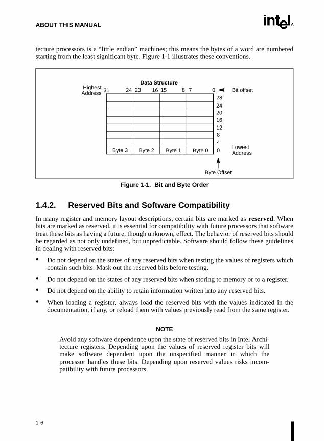
1.4.1. Bit and Byte Order
In illustrations of data structures in memory, smaller addresses appear toward the bottom of thefigure; addresses increase toward the top. Bit positions are numbered from right to left. Thenumerical value of a set bit is equal to two raised to the power of the bit position. Intel Archi-
1-5
ABOUT THIS MANUAL
bered
ftwareshouldelines
tecture processors is a “little endian” machines; this means the bytes of a word are numstarting from the least significant byte. Figure 1-1 illustrates these conventions.
1.4.2. Reserved Bits and Software Compatibility
In many register and memory layout descriptions, certain bits are marked as reserved. Whenbits are marked as reserved, it is essential for compatibility with future processors that sotreat these bits as having a future, though unknown, effect. The behavior of reserved bits be regarded as not only undefined, but unpredictable. Software should follow these guidin dealing with reserved bits:
• Do not depend on the states of any reserved bits when testing the values of registers whichcontain such bits. Mask out the reserved bits before testing.
• Do not depend on the states of any reserved bits when storing to memory or to a register.
• Do not depend on the ability to retain information written into any reserved bits.
• When loading a register, always load the reserved bits with the values indicated in thedocumentation, if any, or reload them with values previously read from the same register.
NOTE
Avoid any software dependence upon the state of reserved bits in Intel Archi-tecture registers. Depending upon the values of reserved register bits willmake software dependent upon the unspecified manner in which theprocessor handles these bits. Depending upon reserved values risks incom-patibility with future processors.
Figure 1-1. Bit and Byte Order
Byte 3
HighestData Structure
Byte 1Byte 2 Byte 0
31 24 23 16 15 8 7 0Address
Lowest
Bit offset28
24201612840 Address
Byte Offset
1-6

ABOUT THIS MANUAL
onfu-
ed as a used tolled an
1.4.3. Instruction Operands
When instructions are represented symbolically, a subset of the Intel Architecture assemblylanguage is used. In this subset, an instruction has the following format:
label: mnemonic argument1, argument2, argument3
where:
• A label is an identifier which is followed by a colon.
• A mnemonic is a reserved name for a class of instruction opcodes which have the samefunction.
• The operands argument1, argument2, and argument3 are optional. There may be from zeroto three operands, depending on the opcode. When present, they take the form of eitherliterals or identifiers for data items. Operand identifiers are either reserved names ofregisters or are assumed to be assigned to data items declared in another part of theprogram (which may not be shown in the example).
When two operands are present in an arithmetic or logical instruction, the right operand is thesource and the left operand is the destination.
For example:
LOADREG: MOV EAX, SUBTOTAL
In this example LOADREG is a label, MOV is the mnemonic identifier of an opcode, EAX isthe destination operand, and SUBTOTAL is the source operand. Some assembly languages putthe source and destination in reverse order.
1.4.4. Hexadecimal and Binary Numbers
Base 16 (hexadecimal) numbers are represented by a string of hexadecimal digits followed bythe character H (for example, F82EH). A hexadecimal digit is a character from the followingset: 0, 1, 2, 3, 4, 5, 6, 7, 8, 9, A, B, C, D, E, and F.
Base 2 (binary) numbers are represented by a string of 1s and 0s, sometimes followed by thecharacter B (for example, 1010B). The “B” designation is only used in situations where csion as to the type of number might arise.
1.4.5. Segmented Addressing
The processor uses byte addressing. This means memory is organized and accesssequence of bytes. Whether one or more bytes are being accessed, a byte address islocate the byte or bytes of memory. The range of memory that can be addressed is caaddress space.
1-7

ABOUT THIS MANUAL
The processor also supports segmented addressing. This is a form of addressing where aprogram may have many independent address spaces, called segments. For example, a programcan keep its code (instructions) and stack in separate segments. Code addresses would alwaysrefer to the code space, and stack addresses would always refer to the stack space. The followingnotation is used to specify a byte address within a segment:
Segment-register:Byte-address
For example, the following segment address identifies the byte at address FF79H in the segmentpointed by the DS register:
DS:FF79H
The following segment address identifies an instruction address in the code segment. The CSregister points to the code segment and the EIP register contains the address of the instruction.
CS:EIP
1.4.6. Exceptions
An exception is an event that typically occurs when an instruction causes an error. For example,an attempt to divide by zero generates an exception. However, some exceptions, such as break-points, occur under other conditions. Some types of exceptions may provide error codes. Anerror code reports additional information about the error. An example of the notation used toshow an exception and error code is shown below.
#PF(fault code)
This example refers to a page-fault exception under conditions where an error code naming atype of fault is reported. Under some conditions, exceptions which produce error codes may notbe able to report an accurate code. In this case, the error code is zero, as shown below for ageneral-protection exception.
#GP(0)
Refer to Chapter 5, Interrupt and Exception Handling, in the Intel Architecture Software Devel-oper’s Manual, Volume 3, for a list of exception mnemonics and their descriptions.
1-8

ABOUT THIS MANUAL
ory
1.5. RELATED LITERATURE
The following books contain additional material related to Intel processors:
• Intel Pentium® Pro Processor Specification Update, Order Number 242689.
• Intel Pentium® Processor Specification Update, Order Number 242480.
• AP-485, Intel Processor Identification and the CPUID Instruction, Order Number 241618.
• AP-578, Software and Hardware Considerations for FPU Exception Handlers for IntelArchitecture Processors, Order Number 242415-001.
• Pentium® Pro Processor Family Developer’s Manual, Volume 1: Specifications, OrderNumber 242690-001.
• Pentium® Processor Family Developer’s Manual, Order Number 241428.
• Intel486™ Microprocessor Data Book, Order Number 240440.
• Intel486™ SX CPU/Intel487™ SX Math Coprocessor Data Book, Order Number 240950.
• Intel486™ DX2 Microprocessor Data Book, Order Number 241245.
• Intel486™ Microprocessor Product Brief Book, Order Number 240459.
• Intel386™ Processor Hardware Reference Manual, Order Number 231732.
• Intel386™ Processor System Software Writer's Guide, Order Number 231499.
• Intel386™ High-Performance 32-Bit CHMOS Microprocessor with Integrated MemManagement, Order Number 231630.
• 376 Embedded Processor Programmer’s Reference Manual, Order Number 240314.
• 80387 DX User’s Manual Programmer’s Reference, Order Number 231917.
• 376 High-Performance 32-Bit Embedded Processor, Order Number 240182.
• Intel386™ SX Microprocessor, Order Number 240187.
• Microprocessor and Peripheral Handbook (Vol. 1), Order Number 230843.
• AP-528, Optimizations for Intel’s 32-Bit Processors, Order Number 242816-001.
1-9

ABOUT THIS MANUAL
1-10

2
Instruction Format

en-
MD
CHAPTER 2INSTRUCTION FORMAT
This chapter describes the instruction format for all Intel Architecture processors.
2.1. GENERAL INSTRUCTION FORMAT
All Intel Architecture instruction encodings are subsets of the general instruction format shownin Figure 2-1. Instructions consist of optional instruction prefixes (in any order), one or twoprimary opcode bytes, an addressing-form specifier (if required) consisting of the ModR/M byteand sometimes the SIB (Scale-Index-Base) byte, a displacement (if required), and an immediatedata field (if required).
2.2. INSTRUCTION PREFIXES
The instruction prefixes are divided into four groups, each with a set of allowable prefix codes:
• Lock and repeat prefixes.
— F0H—LOCK prefix.
— F2H—REPNE/REPNZ prefix (used only with string instructions).
— F3H—REP prefix (used only with string instructions and Streaming SIMD Extsions).
— F3H—REPE/REPZ prefix (used only with string instructions and Streaming SIExtensions).
Figure 2-1. Intel Architecture Instruction Format
InstructionPrefixes Opcode ModR/M SIB Displacement Immediate
Mod R/MReg/Opcode
027 6 5 3
Scale Base
027 6 5 3
Index
Immediatedata of
1, 2, or 4bytes or none
Addressdisplacementof 1, 2, or 4
bytes or none
1 byte(if required)
1 byte(if required)
1 or 2 byteopcode
Up to fourprefixes of
1-byte each(optional)
2-1

INSTRUCTION FORMAT
codedheseoding,ing on
r byteree
• Segment override.
— 2EH—CS segment override prefix.
— 36H—SS segment override prefix.
— 3EH—DS segment override prefix.
— 26H—ES segment override prefix.
— 64H—FS segment override prefix.
— 65H—GS segment override prefix.
• Operand-size override, 66H
• Address-size override, 67H
For each instruction, one prefix may be used from each of these groups and be placed in anyorder. The effect of redundant prefixes (more than one prefix from a group) is undefined andmay vary from processor to processor.
• Streaming SIMD Extensions prefix, 0FH
The nature of Streaming SIMD Extensions allows the use of existing instruction formats.Instructions use the ModR/M format and are preceded by the 0F prefix byte. In general, opera-tions are not duplicated to provide two directions (i.e. separate load and store variants). For moreinformation, see Section B.4.1., “Instruction Prefixes” in Appendix B, Instruction Formats andEncodings.
2.3. OPCODE
The primary opcode is either 1 or 2 bytes. An additional 3-bit opcode field is sometimes enin the ModR/M byte. Smaller encoding fields can be defined within the primary opcode. Tfields define the direction of the operation, the size of displacements, the register enccondition codes, or sign extension. The encoding of fields in the opcode varies, dependthe class of operation.
2.4. MODR/M AND SIB BYTES
Most instructions that refer to an operand in memory have an addressing-form specifie(called the ModR/M byte) following the primary opcode. The ModR/M byte contains thfields of information:
• The mod field combines with the r/m field to form 32 possible values: eight registers and24 addressing modes.
• The reg/opcode field specifies either a register number or three more bits of opcode infor-mation. The purpose of the reg/opcode field is specified in the primary opcode.
• The r/m field can specify a register as an operand or can be combined with the mod field toencode an addressing mode.
2-2
INSTRUCTION FORMAT
tiveM fields theeralings fieldch-
ersther the
od anddressd.
eld arew isecondSIMD, then repre-
Certain encodings of the ModR/M byte require a second addressing byte, the SIB byte, to fullyspecify the addressing form. The base-plus-index and scale-plus-index forms of 32-bitaddressing require the SIB byte. The SIB byte includes the following fields:
• The scale field specifies the scale factor.
• The index field specifies the register number of the index register.
• The base field specifies the register number of the base register.
Refer to Section 2.6. for the encodings of the ModR/M and SIB bytes.
2.5. DISPLACEMENT AND IMMEDIATE BYTES
Some addressing forms include a displacement immediately following either the ModR/M orSIB byte. If a displacement is required, it can be 1, 2, or 4 bytes.
If the instruction specifies an immediate operand, the operand always follows any displacementbytes. An immediate operand can be 1, 2, or 4 bytes.
2.6. ADDRESSING-MODE ENCODING OF MODR/M AND SIB BYTES
The values and the corresponding addressing forms of the ModR/M and SIB bytes are shown inTables 2-1 through 2-3. The 16-bit addressing forms specified by the ModR/M byte are in Table2-1, and the 32-bit addressing forms specified by the ModR/M byte are in Table 2-2. Table 2-3shows the 32-bit addressing forms specified by the SIB byte.
In Tables 2-1 and 2-2, the first column (labeled “Effective Address”) lists 32 different effecaddresses that can be assigned to one operand of an instruction by using the Mod and R/of the ModR/M byte. The first 24 give the different ways of specifying a memory location;last eight (specified by the Mod field encoding 11B) give the ways of specifying the genpurpose, MMX™ technology, and SIMD floating-point registers. Each of the register encodlist five possible registers. For example, the first register-encoding (selected by the R/Mencoding of 000B) indicates the general-purpose registers EAX, AX or AL, the MMX™ tenology register MM0, or the SIMD floating-point register XMM0. Which of these five registis used is determined by the opcode byte and the operand-size attribute, which select eiEAX register (32 bits) or AX register (16 bits).
The second and third columns in Tables 2-1 and 2-2 gives the binary encodings of the MR/M fields in the ModR/M byte, respectively, required to obtain the associated effective adlisted in the first column. All 32 possible combinations of the Mod and R/M fields are liste
Across the top of Tables 2-1 and 2-2, the eight possible values of the 3-bit Reg/Opcode filisted, in decimal (sixth row from top) and in binary (seventh row from top). The seventh rolabeled “REG=”, which represents the use of these three bits to give the location of a soperand, which must be a general-purpose register, an MMX™ technology register, or a floating-point register. If the instruction does not require a second operand to be specifiedthe 3 bits of the Reg/Opcode field may be used as an extension of the opcode, which is
2-3

INSTRUCTION FORMAT
, andIMDbers,
h they the
al)”). Bitsecifies
sented by the sixth row, labeled “/digit (Opcode)”. The five rows above give the byte, worddoubleword general-purpose registers; the MMX™ technology registers; the Streaming SExtensions registers; and SIMD floating-point registers that correspond to the register numwith the same assignments as for the R/M field when Mod field encoding is 11B. As witR/M field register options, which of the five possible registers is used is determined bopcode byte along with the operand-size attribute.
The body of Tables 2-1 and 2-2 (under the label “Value of ModR/M Byte (in Hexadecimcontains a 32 by 8 array giving all of the 256 values of the ModR/M byte, in hexadecimal3, 4 and 5 are specified by the column of the table in which a byte resides, and the row spbits 0, 1 and 2, and also bits 6 and 7.
2-4

INSTRUCTION FORMAT
NOTES:
1. The default segment register is SS for the effective addresses containing a BP index, DS for other effec-tive addresses.
2. The “disp16” nomenclature denotes a 16-bit displacement following the ModR/M byte, to be added to theindex.
3. The “disp8” nomenclature denotes an 8-bit displacement following the ModR/M byte, to be sign-extendedand added to the index.
Table 2-1. 16-Bit Addressing Forms with the ModR/M Byter8(/r)r16(/r)r32(/r)mm(/r)xmm(/r)/digit (Opcode)REG =
ALAXEAXMM0XMM00000
CLCXECXMM1XMM11001
DLDXEDXMM2XMM22010
BLBXEBXMM3XMM33011
AHSPESPMM4XMM44100
CHBP1
EBPMM5XMM55101
DHSIESIMM6XMM66110
BHDIEDIMM7XMM77111
EffectiveAddress Mod R/M Value of ModR/M Byte (in Hexadecimal)
[BX+SI][BX+DI][BP+SI][BP+DI][SI][DI]disp162
[BX]
00 000001010011100101110111
0001020304050607
08090A0B0C0D0E0F
1011121314151617
18191A1B1C1D1E1F
2021222324252627
28292A2B2C2D2E2F
3031323334353637
38393A3B3C3D3E3F
[BX+SI]+disp83
[BX+DI]+disp8[BP+SI]+disp8[BP+DI]+disp8[SI]+disp8[DI]+disp8[BP]+disp8[BX]+disp8
01 000001010011100101110111
4041424344454647
48494A4B4C4D4E4F
5051525354555657
58595A5B5C5D5E5F
6061626364656667
68696A6B6C6D6E6F
7071727374757677
78797A7B7C7D7E7F
[BX+SI]+disp16[BX+DI]+disp16[BP+SI]+disp16[BP+DI]+disp16[SI]+disp16[DI]+disp16[BP]+disp16[BX]+disp16
10 000001010011100101110111
8081828384858687
88898A8B8C8D8E8F
9091929394959697
98999A9B9C9D9E9F
A0A1A2A3A4A5A6A7
A8A9AAABACADAEAF
B0B1B2B3B4B5B6B7
B8B9BABBBCBDBEBF
EAX/AX/AL/MM0/XMM0ECX/CX/CL/MM1/XMM1EDX/DX/DL/MM2/XMM2EBX/BX/BL/MM3/XMM3ESP/SP/AHMM4/XMM4EBP/BP/CH/MM5/XMM5ESI/SI/DH/MM6/XMM6EDI/DI/BH/MM7/XMM7
11 000001010011100101110111
C0C1C2C3C4C5C6C7
C8C9CACBCCCDCECF
D0D1D2D3D4D5D6D7
D8D9DADBDCDDDEDF
E0EQE2E3E4E5E6E7
E8E9EAEBECEDEEEF
F0F1F2F3F4F5F6F7
F8F9FAFBFCFDFEFF
2-5

INSTRUCTION FORMAT
NOTES:
1. The [--][--] nomenclature means a SIB follows the ModR/M byte.
2. The disp32 nomenclature denotes a 32-bit displacement following the SIB byte, to be added to the index.
3. The disp8 nomenclature denotes an 8-bit displacement following the SIB byte, to be sign-extended andadded to the index.
Table 2-2. 32-Bit Addressing Forms with the ModR/M Byter8(/r)r16(/r)r32(/r)mm(/r)xmm(/r)/digit (Opcode)REG =
ALAXEAXMM0XMM00000
CLCXECXMM1XMM11001
DLDXEDXMM2XMM22010
BLBXEBXMM3XMM33011
AHSPESPMM4XMM44100
CHBPEBPMM5XMM55101
DHSIESIMM6XMM66110
BHDIEDIMM7XMM77111
EffectiveAddress Mod R/M Value of ModR/M Byte (in Hexadecimal)
[EAX][ECX][EDX][EBX][--][--]1
disp322
[ESI][EDI]
00 000001010011100101110111
0001020304050607
08090A0B0C0D0E0F
1011121314151617
18191A1B1C1D1E1F
2021222324252627
28292A2B2C2D2E2F
3031323334353637
38393A3B3C3D3E3F
disp8[EAX]3
disp8[ECX]disp8[EDX]disp8[EBX];disp8[--][--]disp8[EBP]disp8[ESI]disp8[EDI]
01 000001010011100101110111
4041424344454647
48494A4B4C4D4E4F
5051525354555657
58595A5B5C5D5E5F
6061626364656667
68696A6B6C6D6E6F
7071727374757677
78797A7B7C7D7E7F
disp32[EAX]disp32[ECX]disp32[EDX]disp32[EBX]disp32[--][--]disp32[EBP]disp32[ESI]disp32[EDI]
10 000001010011100101110111
8081828384858687
88898A8B8C8D8E8F
9091929394959697
98999A9B9C9D9E9F
A0A1A2A3A4A5A6A7
A8A9AAABACADAEAF
B0B1B2B3B4B5B6B7
B8B9BABBBCBDBEBF
EAX/AX/AL/MM0/XMM0ECX/CX/CL/MM1/XMM1EDX/DX/DL/MM2XMM2EBX/BX/BL/MM3/XMM3ESP/SP/AH/MM4/XMM4EBP/BP/CH/MM5/XMM5ESI/SI/DH/MM6/XMM6EDI/DI/BH/MM7/XMM7
11 000001010011100101110111
C0C1C2C3C4C5C6C7
C8C9CACBCCCDCECF
D0D1D2D3D4D5D6D7
D8D9DADBDCDDDEDF
E0E1E2E3E4E5E6E7
E8E9EAEBECEDEEEF
F0F1F2F3F4F5F6F7
F8F9FAFBFCFDFEFF
2-6

INSTRUCTION FORMAT
Table 2-3 is organized similarly to Tables 2-1 and 2-2, except that its body gives the 256 possiblevalues of the SIB byte, in hexadecimal. Which of the 8 general-purpose registers will be used asbase is indicated across the top of the table, along with the corresponding values of the base field(bits 0, 1 and 2) in decimal and binary. The rows indicate which register is used as the index(determined by bits 3, 4 and 5) along with the scaling factor (determined by bits 6 and 7).
NOTE:
1. The [*] nomenclature means a disp32 with no base if MOD is 00, [EBP] otherwise. This provides thefollowing addressing modes:
disp32[index] (MOD=00).disp8[EBP][index] (MOD=01).disp32[EBP][index] (MOD=10).
Table 2-3. 32-Bit Addressing Forms with the SIB Byter32Base =Base =
EAX0000
ECX1001
EDX2010
EBX3011
ESP4100
[*]5101
ESI6110
EDI7111
Scaled Index SS Index Value of SIB Byte (in Hexadecimal)
[EAX][ECX][EDX][EBX]none[EBP][ESI][EDI]
00 000001010011100101110111
0008101820283038
0109111921293139
020A121A222A323A
030B131B232B333B
040C141C242C343C
050D151D252D353D
060E161E262E363E
070F171F272F373F
[EAX*2][ECX*2][EDX*2][EBX*2]none[EBP*2][ESI*2][EDI*2]
01 000001010011100101110111
4048505860687078
4149515961697179
424A525A626A727A
434B535B636B737B
444C545C646C747C
454D555D656D757D
464E565E666E767E
474F575F676F777F
[EAX*4][ECX*4][EDX*4][EBX*4]none[EBP*4][ESI*4][EDI*4]
10 000001010011100101110111
80889098A0A8B0B8
81899189A1A9B1B9
828A929AA2AAB2BA
838B939BA3ABB3BB
848C949CA4ACB4BC
858D959DA5ADB5BD
868E969EA6AEB6BE
878F979FA7AFB7BF
[EAX*8][ECX*8][EDX*8][EBX*8]none[EBP*8][ESI*8][EDI*8]
11 000001010011100101110111
C0C8D0D8E0E8F0F8
C1C9D1D9E1E9F1F9
C2CAD2DAE2EAF2FA
C3CBD3DBE3EBF3FB
C4CCD4DCE4ECF4FC
C5CDD5DDE5EDF5FD
C6CED6DEE6EEF6FE
C7CFD7DFE7EFF7FF
2-7

INSTRUCTION FORMAT
2-8
3
Instruction Set Reference

Thes are
ription.pera-ister,
refer-ntions
crip-
CHAPTER 3INSTRUCTION SET REFERENCE
This chapter describes the complete Intel Architecture instruction set, including the integer,floating-point, MMX™ technology, Streaming SIMD Extensions, and system instructions.instruction descriptions are arranged in alphabetical order. For each instruction, the formgiven for each operand combination, including the opcode, operands required, and a descAlso given for each instruction are a description of the instruction and its operands, an otional description, a description of the effect of the instructions on flags in the EFLAGS regand a summary of the exceptions that can be generated.
3.1. INTERPRETING THE INSTRUCTION REFERENCE PAGES
This section describes the information contained in the various sections of the instructionence pages that make up the majority of this chapter. It also explains the notational conveand abbreviations used in these sections.
3.1.1. Instruction Format
The following is an example of the format used for each Intel Architecture instruction destion in this chapter:
3-1

INSTRUCTION SET REFERENCE
ction. appear
seses an
CMC—Complement Carry Flag
3.1.1.1. OPCODE COLUMN
The “Opcode” column gives the complete object code produced for each form of the instruWhen possible, the codes are given as hexadecimal bytes, in the same order in which theyin memory. Definitions of entries other than hexadecimal bytes are as follows:
• /digit—A digit between 0 and 7 indicates that the ModR/M byte of the instruction uonly the r/m (register or memory) operand. The reg field contains the digit that providextension to the instruction's opcode.
• /r— Indicates that the ModR/M byte of the instruction contains both a register operand andan r/m operand.
• cb, cw, cd, cp—A 1-byte (cb), 2-byte (cw), 4-byte (cd), or 6-byte (cp) value following theopcode that is used to specify a code offset and possibly a new value for the code segmentregister.
• ib, iw, id—A 1-byte (ib), 2-byte (iw), or 4-byte (id) immediate operand to the instructionthat follows the opcode, ModR/M bytes or scale-indexing bytes. The opcode determines ifthe operand is a signed value. All words and doublewords are given with the low-orderbyte first.
• +rb, +rw, +rd— A register code, from 0 through 7, added to the hexadecimal byte given atthe left of the plus sign to form a single opcode byte. The register codes are given in Table3-1.
• +i—A number used in floating-point instructions when one of the operands is ST(i) fromthe FPU register stack. The number i (which can range from 0 to 7) is added to thehexadecimal byte given at the left of the plus sign to form a single opcode byte.
Opcode Instruction Description
F5 CMC Complement carry flag
3-2

INSTRUCTION SET REFERENCE
in ann the
on to
tionof 16
ofhement
ment.s; the
BP,
–128 orword.
te is
3.1.1.2. INSTRUCTION COLUMN
The “Instruction” column gives the syntax of the instruction statement as it would appearASM386 program. The following is a list of the symbols used to represent operands iinstruction statements:
• rel8—A relative address in the range from 128 bytes before the end of the instructi127 bytes after the end of the instruction.
• rel16 and rel32—A relative address within the same code segment as the instrucassembled. The rel16 symbol applies to instructions with an operand-size attribute bits; the rel32 symbol applies to instructions with an operand-size attribute of 32 bits.
• ptr16:16 and ptr16:32—A far pointer, typically in a code segment different from that the instruction. The notation 16:16 indicates that the value of the pointer has two parts. Tvalue to the left of the colon is a 16-bit selector or value destined for the code segregister. The value to the right corresponds to the offset within the destination segThe ptr16:16 symbol is used when the instruction's operand-size attribute is 16 bitptr16:32 symbol is used when the operand-size attribute is 32 bits.
• r8—One of the byte general-purpose registers AL, CL, DL, BL, AH, CH, DH, or BH.
• r16—One of the word general-purpose registers AX, CX, DX, BX, SP, BP, SI, or DI.
• r32—One of the doubleword general-purpose registers EAX, ECX, EDX, EBX, ESP, EESI, or EDI.
• imm8—An immediate byte value. The imm8 symbol is a signed number between and +127 inclusive. For instructions in which imm8 is combined with a worddoubleword operand, the immediate value is sign-extended to form a word or doubleThe upper byte of the word is filled with the topmost bit of the immediate value.
• imm16—An immediate word value used for instructions whose operand-size attribu16 bits. This is a number between –32,768 and +32,767 inclusive.
Table 3-1. Register Encodings Associated with the +rb, +rw, and +rd Nomenclature
rb rw rd
AL = 0 AX = 0 EAX = 0
CL = 1 CX = 1 ECX = 1
DL = 2 DX = 2 EDX = 2
BL = 3 BX = 3 EBX = 3
rb rw rd
AH = 4 SP = 4 ESP = 4
CH = 5 BP = 5 EBP = 5
DH = 6 SI = 6 ESI = 6
BH = 7 DI = 7 EDI = 7
3-3

INSTRUCTION SET REFERENCE
nd- and
(AL,
hose, CX,y the
tionsrs are:t the
, but the
, but the
ame, with
the
only
ers.r. The
sessing
UNDdices.oadding
,ss is
n the
• imm32—An immediate doubleword value used for instructions whose operasize attribute is 32 bits. It allows the use of a number between +2,147,483,647–2,147,483,648 inclusive.
• r/m8—A byte operand that is either the contents of a byte general-purpose registerBL, CL, DL, AH, BH, CH, and DH), or a byte from memory.
• r/m16—A word general-purpose register or memory operand used for instructions woperand-size attribute is 16 bits. The word general-purpose registers are: AX, BXDX, SP, BP, SI, and DI. The contents of memory are found at the address provided beffective address computation.
• r/m32—A doubleword general-purpose register or memory operand used for instrucwhose operand-size attribute is 32 bits. The doubleword general-purpose registeEAX, EBX, ECX, EDX, ESP, EBP, ESI, and EDI. The contents of memory are found aaddress provided by the effective address computation.
• m—A 16- or 32-bit operand in memory.
• m8—A byte operand in memory, usually expressed as a variable or array namepointed to by the DS:(E)SI or ES:(E)DI registers. This nomenclature is used only withstring instructions and the XLAT instruction.
• m16—A word operand in memory, usually expressed as a variable or array namepointed to by the DS:(E)SI or ES:(E)DI registers. This nomenclature is used only withstring instructions.
• m32—A doubleword operand in memory, usually expressed as a variable or array nbut pointed to by the DS:(E)SI or ES:(E)DI registers. This nomenclature is used onlythe string instructions.
• m64—A memory quadword operand in memory. This nomenclature is used only withCMPXCHG8B instruction.
• m128—A memory double quadword operand in memory. This nomenclature is usedwith the Streaming SIMD Extensions.
• m16:16, m16:32—A memory operand containing a far pointer composed of two numbThe number to the left of the colon corresponds to the pointer's segment selectonumber to the right corresponds to its offset.
• m16&32, m16&16, m32&32—A memory operand consisting of data item pairs whosizes are indicated on the left and the right side of the ampersand. All memory addremodes are allowed. The m16&16 and m32&32 operands are used by the BOinstruction to provide an operand containing an upper and lower bounds for array inThe m16&32 operand is used by LIDT and LGDT to provide a word with which to lthe limit field, and a doubleword with which to load the base field of the corresponGDTR and IDTR registers.
• moffs8, moffs16, moffs32—A simple memory variable (memory offset) of type byteword, or doubleword used by some variants of the MOV instruction. The actual addregiven by a simple offset relative to the segment base. No ModR/M byte is used i
3-4

INSTRUCTION SET REFERENCE
SS=2,
ly)
nt
e:
e:
rynts
bitund
bitare
bitare
bitare
usore
rands.
instruction. The number shown with moffs indicates its size, which is determined by theaddress-size attribute of the instruction.
• Sreg—A segment register. The segment register bit assignments are ES=0, CS=1, DS=3, FS=4, and GS=5.
• m32real, m64real, m80real—A single-, double-, and extended-real (respectivefloating-point operand in memory.
• m16int, m32int, m64int—A word-, short-, and long-integer (respectively) floating-poioperand in memory.
• ST or ST(0)—The top element of the FPU register stack.
• ST(i)—The ith element from the top of the FPU register stack. (i = 0 through 7)
• mm—An MMX™ technology register. The 64-bit MMX™ technology registers arMM0 through MM7.
• xmm—A SIMD floating-point register. The 128-bit SIMD floating-point registers arXMM0 through XMM7.
• mm/m32—The low order 32 bits of an MMX™ technology register or a 32-bit memooperand. The 64-bit MMX™ technology registers are: MM0 through MM7. The conteof memory are found at the address provided by the effective address computation.
• mm/m64—An MMX™ technology register or a 64-bit memory operand. The 64-MMX™ technology registers are: MM0 through MM7. The contents of memory are foat the address provided by the effective address computation.
• xmm/m32—A SIMD floating-points register or a 32-bit memory operand. The 128-SIMD floating-point registers are XMM0 through XMM7. The contents of memory found at the address provided by the effective address computation.
• xmm/m64—A SIMD floating-point register or a 64-bit memory operand. The 64-SIMD floating-point registers are XMM0 through XMM7. The contents of memory found at the address provided by the effective address computation.
• xmm/m128—A SIMD floating-point register or a 128-bit memory operand. The 128-SIMD floating-point registers are XMM0 through XMM7. The contents of memory found at the address provided by the effective address computation.
3.1.1.3. DESCRIPTION COLUMN
The “Description” column following the “Instruction” column briefly explains the varioforms of the instruction. The following “Description” and “Operation” sections contain mdetails of the instruction's operation.
3.1.1.4. DESCRIPTION
The “Description” section describes the purpose of the instructions and the required opeIt also discusses the effect of the instruction on flags.
3-5

INSTRUCTION SET REFERENCE
f thee algo-
dicatess read
andount
izetifiere, the of the
3.1.2. Operation
The “Operation” section contains an algorithmic description (written in pseudo-code) oinstruction. The pseudo-code uses a notation similar to the Algol or Pascal language. Thrithms are composed of the following elements:
• Comments are enclosed within the symbol pairs “(*” and “*)”.
• Compound statements are enclosed in keywords, such as IF, THEN, ELSE, and FI for an ifstatement, DO and OD for a do statement, or CASE ... OF and ESAC for a case statement.
• A register name implies the contents of the register. A register name enclosed in bracketsimplies the contents of the location whose address is contained in that register. Forexample, ES:[DI] indicates the contents of the location whose ES segment relative addressis in register DI. [SI] indicates the contents of the address contained in register SI relativeto SI’s default segment (DS) or overridden segment.
• Parentheses around the “E” in a general-purpose register name, such as (E)SI, inthat an offset is read from the SI register if the current address-size attribute is 16 or ifrom the ESI register if the address-size attribute is 32.
• Brackets are also used for memory operands, where they mean that the contents of thememory location is a segment-relative offset. For example, [SRC] indicates that thecontents of the source operand is a segment-relative offset.
• A ← B; indicates that the value of B is assigned to A.
• The symbols =, ≠, ≥, and ≤ are relational operators used to compare two values, meaningequal, not equal, greater or equal, less or equal, respectively. A relational expression suchas A = B is TRUE if the value of A is equal to B; otherwise it is FALSE.
• The expression “<< COUNT” and “>> COUNT” indicates that the destination opershould be shifted left or right, respectively, by the number of bits indicated by the coperand.
The following identifiers are used in the algorithmic descriptions:
• OperandSize and AddressSize—The OperandSize identifier represents the operand-sattribute of the instruction, which is either 16 or 32 bits. The AddressSize idenrepresents the address-size attribute, which is either 16 or 32 bits. For examplfollowing pseudo-code indicates that the operand-size attribute depends on the formCMPS instruction used.
IF instruction = CMPSWTHEN OperandSize ← 16;ELSE
IF instruction = CMPSDTHEN OperandSize ← 32;
FI;FI;
3-6

INSTRUCTION SET REFERENCE
1
thetion
e
f thelue ofssedxtend
thebyte of
tribute
italue ).
bit value
32767
eduratede 255
e. Ifif it is
lue.0H); if
lue.if it is
Refer to Section 3.8., Operand-Size and Address-Size Attributes in Chapter 3, BasicExecution Environment of the Intel Architecture Software Developer’s Manual, Volume ,for general guidelines on how these attributes are determined.
• StackAddrSize—Represents the stack address-size attribute associated withinstruction, which has a value of 16 or 32 bits. For more information, refer to Sec4.2.3., Address-Size Attributes for Stack Accesses in Chapter 4, Procedure Calls,Interrupts, and Exceptions of the Intel Architecture Software Developer’s Manual, Volum1.
• SRC—Represents the source operand.
• DEST—Represents the destination operand.
The following functions are used in the algorithmic descriptions:
• ZeroExtend(value)—Returns a value zero-extended to the operand-size attribute oinstruction. For example, if the operand-size attribute is 32, zero extending a byte va–10 converts the byte from F6H to a doubleword value of 000000F6H. If the value pato the ZeroExtend function and the operand-size attribute are the same size, ZeroEreturns the value unaltered.
• SignExtend(value)—Returns a value sign-extended to the operand-size attribute ofinstruction. For example, if the operand-size attribute is 32, sign extending a containing the value –10 converts the byte from F6H to a doubleword valueFFFFFFF6H. If the value passed to the SignExtend function and the operand-size atare the same size, SignExtend returns the value unaltered.
• SaturateSignedWordToSignedByte—Converts a signed 16-bit value to a signed 8-bvalue. If the signed 16-bit value is less than –128, it is represented by the saturated v–128 (80H); if it is greater than 127, it is represented by the saturated value 127 (7FH
• SaturateSignedDwordToSignedWord—Converts a signed 32-bit value to a signed 16-value. If the signed 32-bit value is less than –32768, it is represented by the saturated–32768 (8000H); if it is greater than 32767, it is represented by the saturated value (7FFFH).
• SaturateSignedWordToUnsignedByte—Converts a signed 16-bit value to an unsign8-bit value. If the signed 16-bit value is less than zero, it is represented by the satvalue zero (00H); if it is greater than 255, it is represented by the saturated valu(FFH).
• SaturateToSignedByte—Represents the result of an operation as a signed 8-bit valuthe result is less than –128, it is represented by the saturated value –128 (80H); greater than 127, it is represented by the saturated value 127 (7FH).
• SaturateToSignedWord—Represents the result of an operation as a signed 16-bit vaIf the result is less than –32768, it is represented by the saturated value –32768 (800it is greater than 32767, it is represented by the saturated value 32767 (7FFFH).
• SaturateToUnsignedByte—Represents the result of an operation as a signed 8-bit vaIf the result is less than zero it is represented by the saturated value zero (00H); greater than 255, it is represented by the saturated value 255 (FFH).
3-7

INSTRUCTION SET REFERENCE
-bit); if it
d
d
ed by intion
tion” the
PU
cethin in the, the
TheffsetD
• SaturateToUnsignedWord—Represents the result of an operation as a signed 16value. If the result is less than zero it is represented by the saturated value zero (00His greater than 65535, it is represented by the saturated value 65535 (FFFFH).
• LowOrderWord(DEST * SRC)—Multiplies a word operand by a word operand anstores the least significant word of the doubleword result in the destination operand.
• HighOrderWord(DEST * SRC)—Multiplies a word operand by a word operand anstores the most significant word of the doubleword result in the destination operand.
• Push(value)—Pushes a value onto the stack. The number of bytes pushed is determinthe operand-size attribute of the instruction. Refer to the “Operation” section“PUSH—Push Word or Doubleword Onto the Stack” in this chapter for more informaon the push operation.
• Pop() removes the value from the top of the stack and returns it. The statement EAX ←Pop(); assigns to EAX the 32-bit value from the top of the stack. Pop will return either aword or a doubleword depending on the operand-size attribute. Refer to the “Operasection in “POP—Pop a Value from the Stack” in this chapter for more information onpop operation.
• PopRegisterStack—Marks the FPU ST(0) register as empty and increments the Fregister stack pointer (TOP) by 1.
• Switch-Tasks—Performs a task switch.
• Bit(BitBase, BitOffset)—Returns the value of a bit within a bit string, which is a sequenof bits in memory or a register. Bits are numbered from low-order to high-order wiregisters and within memory bytes. If the base operand is a register, the offset can berange 0..31. This offset addresses a bit within the indicated register. An examplefunction Bit[EAX, 21] is illustrated in Figure 3-1.
If BitBase is a memory address, BitOffset can range from –2 GBits to 2 GBits. addressed bit is numbered (Offset MOD 8) within the byte at address (BitBase + (BitODIV 8)), where DIV is signed division with rounding towards negative infinity, and MOreturns a positive number. This operation is illustrated in Figure 3-2.
Figure 3-1. Bit Offset for BIT[EAX,21]
02131
BitOffset = 21
3-8

INSTRUCTION SET REFERENCE
MDion.ngly
list ofh
isisters.r opti-nal andic thattionion to
3.1.3. Intel C/C++ Compiler Intrinsics Equivalent
The Pentium® with MMX™ technology, Pentium® II, and Pentium® III processors have charac-teristics that enable the development of advanced multimedia applications. This sectiondescribes the compiler intrinsic equivalents that can be used with the Intel C/C++ Compiler.
Intrinsics are special coding extensions that allow using the syntax of C function calls and Cvariables instead of hardware registers. Using these intrinsics frees programmers from havingto manage registers and assembly programming. Further, the compiler optimizes the instructionscheduling so that executables runs faster.
The following sections discuss the intrinsics API and the MMX™ technology and SIfloating-point intrinsics. Each intrinsic equivalent is listed with the instruction descriptThere may be additional intrinsics that do not have an instruction equivalent. It is strorecommended that the reader reference the compiler documentation for the completesupported intrinsics. Please refer to the Intel C/C++ Compiler User’s Guide for Win32* Systems WitStreaming SIMD Extension Support (Order Number 718195-00B). Refer to Appendix C, Compiler Intrin-sics and Functional Equivalents for more information on using intrinsics.
Most of the intrinsics that use __m64 operands have two different names. If two intrinsic namesare shown for the same equivalent, the first name is the intrinsic for Intel C/C++ Compiler ver-sions prior to 4.0 and the second name should be used with the Intel C/C++ Compiler version4.0 and future versions. The Intel C/C++ Compiler version 4.0 will support the old intrinsicnames. Programs written using pre-4.0 intrinsic names will compile with version 4.0. Version4.0 intrinsic names will not compile on pre-4.0 compilers.
3.1.3.1. THE INTRINSICS API
The benefit of coding with MMX™ technology intrinsics and SIMD floating-point intrinsicsthat you can use the syntax of C function calls and C variables instead of hardware regThis frees you from managing registers and programming assembly. Further, the compilemizes the instruction scheduling so that your executable runs faster. For each computatiodata manipulation instruction in the new instruction set, there is a corresponding C intrinsimplements it directly. The intrinsics allow you to specify the underlying implementa(instruction selection) of an algorithm yet leave instruction scheduling and register allocatthe compiler.
3-9

INSTRUCTION SET REFERENCE
pecifics, 32- type,
andion
data is in thers ino repre- objectsopera-
opera-ost)
this,
3.1.3.2. MMX™ TECHNOLOGY INTRINSICS
The MMX™ technology intrinsics are based on a new __m64 data type to represent the scontents of an MMX™ technology register. You can specify values in bytes, short integerbit values, or a 64-bit object. The __m64 data type, however, is not a basic ANSI C dataand therefore you must observe the following usage restrictions:
• Use __m64 data only on the left-hand side of an assignment, as a return value, or as aparameter. You cannot use it with other arithmetic expressions ("+", ">>", and so on).
• Use __m64 objects in aggregates, such as unions to access the byte elements and structures; theaddress of an __m64 object may be taken.
• Use __m64 data only with the MMX™ technology intrinsics described in this guidethe Intel C/C++ Compiler User’s Guide for Win32* Systems With Streaming SIMD ExtensSupport (Order Number 718195-00B). Refer to Appendix C, Compiler Intrinsics and FunctionalEquivalents for more information on using intrinsics.
3.1.3.3. SIMD FLOATING-POINT INTRINSICS
The __m128 data type is used to represent the contents of an xmm register, which is either fourpacked single-precision floating-point values or one scalar single-precision number. The__m128 data type is not a basic ANSI C datatype and therefore some restrictions are placed onits usage:
• Use __m128 only on the left-hand side of an assignment, as a return value, or as aparameter. Do not use it in other arithmetic expressions such as "+" and ">>".
• Do not initialize __m128 with literals; there is no way to express 128-bit constants.
• Use __m128 objects in aggregates, such as unions (for example, to access the floatelements) and structures. The address of an __m128 object may be taken.
• Use __m128 data only with the intrinsics described in this user’s guide. Refer toAppendix C, Compiler Intrinsics and Functional Equivalents for more information on usingintrinsics.
The compiler aligns __m128 local data to 16B boundaries on the stack. Global __m128 also 16B-aligned. (To align float arrays, you can use the alignment declspec describedfollowing section.) Because the new instruction set treats the SIMD floating-point registethe same way whether you are using packed or scalar data, there is no __m32 datatype tsent scalar data as you might expect. For scalar operations, you should use the __m128and the “scalar” forms of the intrinsics; the compiler and the processor implement these tions with 32-bit memory references.
The suffixes ps and ss are used to denote “packed single” and “scalar single” precision tions. The packed floats are represented in right-to-left order, with the lowest word (right-mbeing used for scalar operations: [z, y, x, w]. To explain how memory storage reflectsconsider the following example.
3-10

INSTRUCTION SET REFERENCE
ementIMD
ion
y themeticr more
ion”e-
The operation
float a[4] = { 1.0, 2.0, 3.0, 4.0 };__m128 t = _mm_load_ps(a);
produces the same result as follows:
__m128 t = _mm_set_ps(4.0, 3.0, 2.0, 1.0);
In other words,
t = [ 4.0, 3.0, 2.0, 1.0 ]
where the “scalar” element is 1.0.
Some intrinsics are “composites” because they require more than one instruction to implthem. You should be familiar with the hardware features provided by the Streaming SExtensions and MMX™ technology when writing programs with the intrinsics.
Keep the following three important issues in mind:
• Certain intrinsics, such as _mm_loadr_ps and _mm_cmpgt_ss, are not directlysupported by the instruction set. While these intrinsics are convenient programmingaids, be mindful of their implementation cost.
• Floating-point data loaded or stored as __m128 objects must generally be 16-byte-aligned.
• Some intrinsics require that their argument be immediates, that is, constant integers(literals), due to the nature of the instruction.
• The result of arithmetic operations acting on two NaN (Not a Number) arguments isundefined. Therefore, FP operations using NaN arguments will not match the expectedbehavior of the corresponding assembly instructions.
For a more detailed description of each intrinsic and additional information related to its usage,refer to the Intel C/C++ Compiler User’s Guide for Win32* Systems With Streaming SIMD ExtensSupport (Order Number 718195-00B). Refer to Appendix C, Compiler Intrinsics and Functional Equiva-lents for more information on using intrinsics.
3.1.4. Flags Affected
The “Flags Affected” section lists the flags in the EFLAGS register that are affected binstruction. When a flag is cleared, it is equal to 0; when it is set, it is equal to 1. The arithand logical instructions usually assign values to the status flags in a uniform manner. Foinformation, refer to Appendix A, EFLAGS Cross-Reference, of the Intel Architecture SoftwareDeveloper’s Manual, Volume 1. Non-conventional assignments are described in the “Operatsection. The values of flags listed as undefined may be changed by the instruction in an indterminate manner. Flags that are not listed are unchanged by the instruction.
3-11

INSTRUCTION SET REFERENCE
each
struc-s givenr codeor codevector
n the
3.1.5. FPU Flags Affected
The floating-point instructions have an “FPU Flags Affected” section that describes howinstruction can affect the four condition code flags of the FPU status word.
3.1.6. Protected Mode Exceptions
The “Protected Mode Exceptions” section lists the exceptions that can occur when the intion is executed in protected mode and the reasons for the exceptions. Each exception ia mnemonic that consists of a pound sign (#) followed by two letters and an optional erroin parentheses. For example, #GP(0) denotes a general protection exception with an errof 0. Table 3-2 associates each two-letter mnemonic with the corresponding interrupt number and exception name. Refer to Chapter 5, Interrupt and Exception Handling, of the IntelArchitecture Software Developer’s Manual, Volume 3, for a detailed description of the excep-tions.
Application programmers should consult the documentation provided with their operatingsystems to determine the actions taken when exceptions occur.
3.1.7. Real-Address Mode Exceptions
The “Real-Address Mode Exceptions” section lists the exceptions that can occur wheinstruction is executed in real-address mode.
Figure 3-2. Memory Bit Indexing
BitBase + 1
0777 5 0 0
BitBase − 2
0777 50 0
BitBase BitBase − 1
BitOffset = +13
BitOffset = −11
BitBase − 1BitBase
3-12

INSTRUCTION SET REFERENCE
n the
NOTES:
1. The UD2 instruction was introduced in the Pentium® Pro processor.
2. This exception was introduced in the Intel486™ processor.
3. This exception was introduced in the Pentium® processor and enhanced in the Pentium®�Pro processor.
3.1.8. Virtual-8086 Mode Exceptions
The “Virtual-8086 Mode Exceptions” section lists the exceptions that can occur wheinstruction is executed in virtual-8086 mode.
Table 3-2. Exception Mnemonics, Names, and Vector Numbers
Vector No. Mnemonic Name Source
0 #DE Divide Error DIV and IDIV instructions.
1 #DB Debug Any code or data reference.
3 #BP Breakpoint INT 3 instruction.
4 #OF Overflow INTO instruction.
5 #BR BOUND Range Exceeded BOUND instruction.
6 #UD Invalid Opcode (Undefined Opcode)
UD2 instruction or reserved opcode.1
7 #NM Device Not Available (No Math Coprocessor)
Floating-point or WAIT/FWAIT instruction.
8 #DF Double Fault Any instruction that can generate an exception, an NMI, or an INTR.
10 #TS Invalid TSS Task switch or TSS access.
11 #NP Segment Not Present Loading segment registers or accessing system segments.
12 #SS Stack Segment Fault Stack operations and SS register loads.
13 #GP General Protection Any memory reference and other protection checks.
14 #PF Page Fault Any memory reference.
16 #MF Floating-Point Error (Math Fault) Floating-point or WAIT/FWAIT instruction.
17 #AC Alignment Check Any data reference in memory.2
18 #MC Machine Check Model dependent.3
19 #XF SIMD Floating-Point Numeric Error
Streaming SIMD Extensions
3-13

INSTRUCTION SET REFERENCE
en at in aciatesn 7.8.,
henionsable. For a
3.1.9. Floating-Point Exceptions
The “Floating-Point Exceptions” section lists additional exceptions that can occur whfloating-point instruction is executed in any mode. All of these exception conditions resulfloating-point error exception (#MF, vector number 16) being generated. Table 3-3 assoeach one- or two-letter mnemonic with the corresponding exception name. Refer to SectioFloating-Point Exception Conditions in Chapter 7, Floating-Point Unit of the Intel ArchitectureSoftware Developer’s Manual, Volume 1, for a detailed description of these exceptions.
3.1.10. SIMD Floating-Point Exceptions - Streaming SIMD Extensions Only
The “SIMD Floating-Point Exceptions” section lists additional exceptions that can occur wa SIMD floating-point instruction is executed in any mode. All of these exception conditresult in a SIMD floating-point error exception (#XF, vector number 19) being generated. T3-4 associates each one-or two-letter mnemonic with the corresponding exception namedetailed description of these exceptions, refer to Chapter 9, Programming with the StreamingSIMD Extension, of the Intel Architecture Software Developer’s Manual, Volume 1.
Table 3-3. Floating-Point Exception Mnemonics and Names
Vector No. Mnemonic Name Source
16#IS#IA
Floating-point invalid operation:- Stack overflow or underflow- Invalid arithmetic operation
- FPU stack overflow or underflow- Invalid FPU arithmetic operation
16 #Z Floating-point divide-by-zero FPU divide-by-zero
16 #D Floating-point denormalized operation
Attempting to operate on a denormal number
16 #O Floating-point numeric overflow FPU numeric overflow
16 #U Floating-point numeric underflow FPU numeric underflow
16 #P Floating-point inexact result (precision)
Inexact result (precision)
3-14
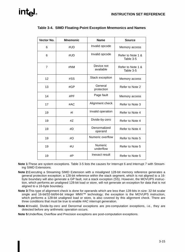
INSTRUCTION SET REFERENCE
Table 3-4. SIMD Floating-Point Exception Mnemonics and Names
Note 1:These are system exceptions. Table 3-5 lists the causes for Interrupt 6 and Interrupt 7 with Stream-ing SIMD Extensions.
Note 2:Executing a Streaming SIMD Extension with a misaligned 128-bit memory reference generates ageneral protection exception; a 128-bit reference within the stack segment, which is not aligned to a 16-byte boundary will also generate a GP fault, not a stack exception (SS). However, the MOVUPS instruc-tion, which performs an unaligned 128-bit load or store, will not generate an exception for data that is notaligned to a 16-byte boundary.
Note 3:This type of alignment check is done for operands which are less than 128-bits in size: 32-bit scalarsingle and 16-bit/32-bit/64-bit integer MMX™ technology; the exception is the MOVUPS instruction,which performs a 128-bit unaligned load or store, is also covered by this alignment check. There arethree conditions that must be true to enable #AC interrupt generation.
Note 4:Invalid, Divide-by-zero and Denormal exceptions are pre-computation exceptions, i.e., they aredetected before any arithmetic operation occurs.
Note 5:Underflow, Overflow and Precision exceptions are post-computation exceptions.
Vector No. Mnemonic Name Source
6 #UD Invalid opcode Memory access
6 #UD Invalid opcode Refer to Note 1 & Table 3-5
7 #NM Device not available
Refer to Note 1 & Table 3-5
12 #SS Stack exception Memory access
13 #GP General protection
Refer to Note 2
14 #PF Page fault Memory access
17 #AC Alignment check Refer to Note 3
19 #I Invalid operation Refer to Note 4
19 #Z Divide-by-zero Refer to Note 4
19 #D Denormalized operand
Refer to Note 4
19 #O Numeric overflow Refer to Note 5
19 #U Numeric underflow
Refer to Note 5
19 #P Inexact result Refer to Note 5
3-15

INSTRUCTION SET REFERENCE
Table 3-5. Streaming SIMD Extensions Faults (Interrupts 6 & 7)
3.2. INSTRUCTION REFERENCE
The remainder of this chapter provides detailed descriptions of each of the Intel Architectureinstructions.
CR0.EM CR0.TS CR4.OSFXSR CPUID.XMM Exception
1 - - - #UD Interrupt 6
0 1 1 1 #NM Interrupt 7
- - 0 - #UD Interrupt 6
- - - 0 #UD Interrupt 6
3-16

INSTRUCTION SET REFERENCE
AAA—ASCII Adjust After Addition
Description
This instruction adjusts the sum of two unpacked BCD values to create an unpacked BCD result.The AL register is the implied source and destination operand for this instruction. The AAAinstruction is only useful when it follows an ADD instruction that adds (binary addition) twounpacked BCD values and stores a byte result in the AL register. The AAA instruction thenadjusts the contents of the AL register to contain the correct 1-digit unpacked BCD result.
If the addition produces a decimal carry, the AH register is incremented by 1, and the CF andAF flags are set. If there was no decimal carry, the CF and AF flags are cleared and the AHregister is unchanged. In either case, bits 4 through 7 of the AL register are cleared to 0.
Operation
IF ((AL AND 0FH) > 9) OR (AF = 1)THEN
AL ← (AL + 6);AH ← AH + 1;AF ← 1;CF ← 1;
ELSEAF ← 0;CF ← 0;
FI;AL ← AL AND 0FH;
Flags Affected
The AF and CF flags are set to 1 if the adjustment results in a decimal carry; otherwise they arecleared to 0. The OF, SF, ZF, and PF flags are undefined.
Exceptions (All Operating Modes)
None.
Opcode Instruction Description
37 AAA ASCII adjust AL after addition
3-17

INSTRUCTION SET REFERENCE
. Thes. Tode (D5
efined.
AAD—ASCII Adjust AX Before Division
Description
This instruction adjusts two unpacked BCD digits (the least-significant digit in the AL registerand the most-significant digit in the AH register) so that a division operation performed on theresult will yield a correct unpacked BCD value. The AAD instruction is only useful when itprecedes a DIV instruction that divides (binary division) the adjusted value in the AX registerby an unpacked BCD value.
The AAD instruction sets the value in the AL register to (AL + (10 * AH)), and then clears theAH register to 00H. The value in the AX register is then equal to the binary equivalent of theoriginal unpacked two-digit (base 10) number in registers AH and AL.
The generalized version of this instruction allows adjustment of two unpacked digits of anynumber base (refer to the “Operation” section below), by setting the imm8 byte to the selectednumber base (for example, 08H for octal, 0AH for decimal, or 0CH for base 12 numbers)AAD mnemonic is interpreted by all assemblers to mean adjust ASCII (base 10) valueadjust values in another number base, the instruction must be hand coded in machine coimm8).
Operation
tempAL ← AL;tempAH ← AH;AL ← (tempAL + (tempAH ∗ imm8)) AND FFH; (* imm8 is set to 0AH for the AAD mnemonic *)AH ← 0
The immediate value (imm8) is taken from the second byte of the instruction.
Flags Affected
The SF, ZF, and PF flags are set according to the result; the OF, AF, and CF flags are und
Exceptions (All Operating Modes)
None.
Opcode Instruction Description
D5 0A AAD ASCII adjust AX before division
D5 ib (No mnemonic) Adjust AX before division to number base imm8
3-18

INSTRUCTION SET REFERENCE
, theal, or adjustust be
efined.
ed, it
AAM—ASCII Adjust AX After Multiply
Description
This instruction adjusts the result of the multiplication of two unpacked BCD values to create apair of unpacked (base 10) BCD values. The AX register is the implied source and destinationoperand for this instruction. The AAM instruction is only useful when it follows an MULinstruction that multiplies (binary multiplication) two unpacked BCD values and stores a wordresult in the AX register. The AAM instruction then adjusts the contents of the AX register tocontain the correct 2-digit unpacked (base 10) BCD result.
The generalized version of this instruction allows adjustment of the contents of the AX to createtwo unpacked digits of any number base (refer to the “Operation” section below). Hereimm8 byte is set to the selected number base (for example, 08H for octal, 0AH for decim0CH for base 12 numbers). The AAM mnemonic is interpreted by all assemblers to meanto ASCII (base 10) values. To adjust to values in another number base, the instruction mhand coded in machine code (D4 imm8).
Operation
tempAL ← AL;AH ← tempAL / imm8; (* imm8 is set to 0AH for the AAD mnemonic *)AL ← tempAL MOD imm8;
The immediate value (imm8) is taken from the second byte of the instruction.
Flags Affected
The SF, ZF, and PF flags are set according to the result. The OF, AF, and CF flags are und
Exceptions (All Operating Modes)
None with the default immediate value of 0AH. If, however, an immediate value of 0 is uswill cause a #DE (divide error) exception.
Opcode Instruction Description
D4 0A AAM ASCII adjust AX after multiply
D4 ib (No mnemonic) Adjust AX after multiply to number base imm8
3-19

INSTRUCTION SET REFERENCE
AAS—ASCII Adjust AL After Subtraction
Description
This instruction adjusts the result of the subtraction of two unpacked BCD values to create aunpacked BCD result. The AL register is the implied source and destination operand for thisinstruction. The AAS instruction is only useful when it follows a SUB instruction that subtracts(binary subtraction) one unpacked BCD value from another and stores a byte result in the ALregister. The AAA instruction then adjusts the contents of the AL register to contain the correct1-digit unpacked BCD result.
If the subtraction produced a decimal carry, the AH register is decremented by 1, and the CF andAF flags are set. If no decimal carry occurred, the CF and AF flags are cleared, and the AHregister is unchanged. In either case, the AL register is left with its top nibble set to 0.
Operation
IF ((AL AND 0FH) > 9) OR (AF = 1)THEN
AL ← AL – 6;AH ← AH – 1;AF ← 1;CF ← 1;
ELSECF ← 0;AF ← 0;
FI;AL ← AL AND 0FH;
Flags Affected
The AF and CF flags are set to 1 if there is a decimal borrow; otherwise, they are cleared to 0.The OF, SF, ZF, and PF flags are undefined.
Exceptions (All Operating Modes)
None.
Opcode Instruction Description
3F AAS ASCII adjust AL after subtraction
3-20

INSTRUCTION SET REFERENCE
ADC—Add with Carry
Description
This instruction adds the destination operand (first operand), the source operand (secondoperand), and the carry (CF) flag and stores the result in the destination operand. The destinationoperand can be a register or a memory location; the source operand can be an immediate, aregister, or a memory location. (However, two memory operands cannot be used in one instruc-tion.) The state of the CF flag represents a carry from a previous addition. When an immediatevalue is used as an operand, it is sign-extended to the length of the destination operand format.
The ADC instruction does not distinguish between signed or unsigned operands. Instead, theprocessor evaluates the result for both data types and sets the OF and CF flags to indicate a carryin the signed or unsigned result, respectively. The SF flag indicates the sign of the signed result.
The ADC instruction is usually executed as part of a multibyte or multiword addition in whichan ADD instruction is followed by an ADC instruction.
Operation
DEST ← DEST + SRC + CF;
Flags Affected
The OF, SF, ZF, AF, CF, and PF flags are set according to the result.
Opcode Instruction Description
14 ib ADC AL,imm8 Add with carry imm8 to AL
15 iw ADC AX,imm16 Add with carry imm16 to AX
15 id ADC EAX,imm32 Add with carry imm32 to EAX
80 /2 ib ADC r/m8,imm8 Add with carry imm8 to r/m8
81 /2 iw ADC r/m16,imm16 Add with carry imm16 to r/m16
81 /2 id ADC r/m32,imm32 Add with CF imm32 to r/m32
83 /2 ib ADC r/m16,imm8 Add with CF sign-extended imm8 to r/m16
83 /2 ib ADC r/m32,imm8 Add with CF sign-extended imm8 into r/m32
10 /r ADC r/m8,r8 Add with carry byte register to r/m8
11 /r ADC r/m16,r16 Add with carry r16 to r/m16
11 /r ADC r/m32,r32 Add with CF r32 to r/m32
12 /r ADC r8,r/m8 Add with carry r/m8 to byte register
13 /r ADC r16,r/m16 Add with carry r/m16 to r16
13 /r ADC r32,r/m32 Add with CF r/m32 to r32
3-21
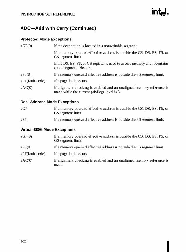
INSTRUCTION SET REFERENCE
ADC—Add with Carry (Continued)
Protected Mode Exceptions
#GP(0) If the destination is located in a nonwritable segment.
If a memory operand effective address is outside the CS, DS, ES, FS, orGS segment limit.
If the DS, ES, FS, or GS register is used to access memory and it containsa null segment selector.
#SS(0) If a memory operand effective address is outside the SS segment limit.
#PF(fault-code) If a page fault occurs.
#AC(0) If alignment checking is enabled and an unaligned memory reference ismade while the current privilege level is 3.
Real-Address Mode Exceptions
#GP If a memory operand effective address is outside the CS, DS, ES, FS, orGS segment limit.
#SS If a memory operand effective address is outside the SS segment limit.
Virtual-8086 Mode Exceptions
#GP(0) If a memory operand effective address is outside the CS, DS, ES, FS, orGS segment limit.
#SS(0) If a memory operand effective address is outside the SS segment limit.
#PF(fault-code) If a page fault occurs.
#AC(0) If alignment checking is enabled and an unaligned memory reference ismade.
3-22

INSTRUCTION SET REFERENCE
ADD—Add
Description
This instruction adds the first operand (destination operand) and the second operand (sourceoperand) and stores the result in the destination operand. The destination operand can be aregister or a memory location; the source operand can be an immediate, a register, or a memorylocation. (However, two memory operands cannot be used in one instruction.) When an imme-diate value is used as an operand, it is sign-extended to the length of the destination operandformat.
The ADD instruction does not distinguish between signed or unsigned operands. Instead, theprocessor evaluates the result for both data types and sets the OF and CF flags to indicate a carryin the signed or unsigned result, respectively. The SF flag indicates the sign of the signed result.
Operation
DEST ← DEST + SRC;
Flags Affected
The OF, SF, ZF, AF, CF, and PF flags are set according to the result.
Opcode Instruction Description
04 ib ADD AL,imm8 Add imm8 to AL
05 iw ADD AX,imm16 Add imm16 to AX
05 id ADD EAX,imm32 Add imm32 to EAX
80 /0 ib ADD r/m8,imm8 Add imm8 to r/m8
81 /0 iw ADD r/m16,imm16 Add imm16 to r/m16
81 /0 id ADD r/m32,imm32 Add imm32 to r/m32
83 /0 ib ADD r/m16,imm8 Add sign-extended imm8 to r/m16
83 /0 ib ADD r/m32,imm8 Add sign-extended imm8 to r/m32
00 /r ADD r/m8,r8 Add r8 to r/m8
01 /r ADD r/m16,r16 Add r16 to r/m16
01 /r ADD r/m32,r32 Add r32 to r/m32
02 /r ADD r8,r/m8 Add r/m8 to r8
03 /r ADD r16,r/m16 Add r/m16 to r16
03 /r ADD r32,r/m32 Add r/m32 to r32
3-23

INSTRUCTION SET REFERENCE
ADD—Add (Continued)
Protected Mode Exceptions
#GP(0) If the destination is located in a nonwritable segment.
If a memory operand effective address is outside the CS, DS, ES, FS, orGS segment limit.
If the DS, ES, FS, or GS register is used to access memory and it containsa null segment selector.
#SS(0) If a memory operand effective address is outside the SS segment limit.
#PF(fault-code) If a page fault occurs.
#AC(0) If alignment checking is enabled and an unaligned memory reference ismade while the current privilege level is 3.
Real-Address Mode Exceptions
#GP If a memory operand effective address is outside the CS, DS, ES, FS, orGS segment limit.
#SS If a memory operand effective address is outside the SS segment limit.
Virtual-8086 Mode Exceptions
#GP(0) If a memory operand effective address is outside the CS, DS, ES, FS, orGS segment limit.
#SS(0) If a memory operand effective address is outside the SS segment limit.
#PF(fault-code) If a page fault occurs.
#AC(0) If alignment checking is enabled and an unaligned memory reference ismade.
3-24
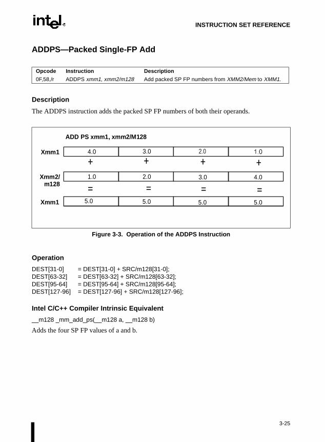
INSTRUCTION SET REFERENCE
ADDPS—Packed Single-FP Add
Description
The ADDPS instruction adds the packed SP FP numbers of both their operands.
Operation
DEST[31-0] = DEST[31-0] + SRC/m128[31-0];DEST[63-32] = DEST[63-32] + SRC/m128[63-32];DEST[95-64] = DEST[95-64] + SRC/m128[95-64];DEST[127-96] = DEST[127-96] + SRC/m128[127-96];
Intel C/C++ Compiler Intrinsic Equivalent
__m128 _mm_add_ps(__m128 a, __m128 b)
Adds the four SP FP values of a and b.
Opcode Instruction Description
0F,58,/r ADDPS xmm1, xmm2/m128 Add packed SP FP numbers from XMM2/Mem to XMM1.
Figure 3-3. Operation of the ADDPS Instruction
Xmm1
Xmm2/m128
Xmm1
1.0
5.0 5.0 5.05.0
2.0 3.0 4.0
ADD PS xmm1, xmm2/M128
4.0 3.0
+ ++
== ==
3-25

INSTRUCTION SET REFERENCE
ADDPS—Packed Single-FP Add (Continued)
Exceptions
General protection exception if not aligned on 16-byte boundary, regardless of segment.
Numeric Exceptions
Overflow, Underflow, Invalid, Precision, Denormal.
Protected Mode Exceptions
#GP(0) For an illegal memory operand effective address in the CS, DS, ES, FS, orGS segments.
#SS(0) For an illegal address in the SS segment.
#PF(fault-code) For a page fault
#UD If CR0.EM = 1.
#NM If TS bit in CR0 is set.
#XM For an unmasked Streaming SIMD Extension numeric exception(CR4.OSXMMEXCPT =1).
#UD For an unmasked Streaming SIMD Extension numeric exception(CR4.OSXMMEXCPT =0).
#UD If CR4.OSFXSR(bit 9) = 0.
#UD If CPUID.XMM(EDX bit 25) = 0.
Real Address Mode Exceptions
Interrupt 13 If any part of the operand would lie outside of the effective address spacefrom 0 to 0FFFFH.
#UD If CR0.EM = 1.
#NM If TS bit in CR0 is set.
#XM For an unmasked Streaming SIMD Extension numeric exception(CR4.OSXMMEXCPT =1).
#UD For an unmasked Streaming SIMD Extension numeric exception(CR4.OSXMMEXCPT =0).
Virtual 8086 Mode Exceptions
Same exceptions as in Real Address Mode.
#PF(fault-code) For a page fault.
3-26

INSTRUCTION SET REFERENCE
ADDSS—Scalar Single-FP Add
Description
The ADDSS instruction adds the lower SP FP numbers of both their operands; the upper threefields are passed through from xmm1.
Operation
DEST[31-0] = DEST[31-0] + SRC/m32[31-0];DEST[63-32] = DEST[63-32];DEST[95-64] = DEST[95-64];DEST[127-96] = DEST[127-96];
Intel C/C++ Compiler Intrinsic Equivalent
__m128 _mm_add_ss(__m128 a, __m128 b)
Adds the lower SP FP (single-precision, floating-point) values of a and b; the upper three SP FPvalues are passed through from a.
Opcode Instruction Description
F3,0F,58, /r ADDSS xmm1, xmm2/m32 Add the lower SP FP number from XMM2/Mem to XMM1.
Figure 3-4. Operation of the ADDSS Instruction
Xmm1
Xmm2/m32
Xmm1 5.0
4.0
ADD SS xmm1, xmm2/m32
+ ++
== ==
3-27

INSTRUCTION SET REFERENCE
3-28
ADDSS—Scalar Single-FP Add (Continued)
Exceptions
None.
Numeric Exceptions
Overflow, Underflow, Invalid, Precision, Denormal.
Protected Mode Exceptions
#GP(0) For an illegal memory operand effective address in the CS, DS, ES,FS, or GS segments.
#SS(0) For an illegal address in the SS segment.
#PF(fault-code) For a page fault.
#UD If CR0.EM = 1.
#NM If TS bit in CR0 is set.
#AC For unaligned memory reference. To enable #AC exceptions, threeconditions must be true (CR0.AM is set; EFLAGS.AC is set; andcurrent CPL is 3).
#XM For an unmasked Streaming SIMD Extension numeric exception(CR4.OSXMMEXCPT =1).
#UD For an unmasked Streaming SIMD Extension numeric exception(CR4.OSXMMEXCPT =0).
#UD If CR4.OSFXSR(bit 9) = 0.
#UD If CPUID.XMM(EDX bit 25) = 0.

INSTRUCTION SET REFERENCE
ADDSS—Scalar Single-FP Add (Continued)
Real Address Mode Exceptions
Interrupt 13 If any part of the operand would lie outside of the effective address spacefrom 0 to 0FFFFH.
#UD If CR0.EM = 1.
#NM If TS bit in CR0 is set.
#XM For an unmasked Streaming SIMD Extension numeric exception(CR4.OSXMMEXCPT =1).
#UD For an unmasked Streaming SIMD Extension numeric exception(CR4.OSXMMEXCPT =0).
#UD If CR4.OSFXSR(bit 9) = 0.
#UD If CPUID.XMM(EDX bit 25) = 0.
Virtual 8086 Mode Exceptions
Same exceptions as in Real Address Mode.
#AC For unaligned memory reference if the current privilege level is 3.
#PF (fault-code) For a page fault.
3-29

INSTRUCTION SET REFERENCE
AND—Logical AND
Description
This instruction performs a bitwise AND operation on the destination (first) and source (second)operands and stores the result in the destination operand location. The source operand can be animmediate, a register, or a memory location; the destination operand can be a register or amemory location. Two memory operands cannot, however, be used in one instruction. Each bitof the instruction result is a 1 if both corresponding bits of the operands are 1; otherwise, itbecomes a 0.
Operation
DEST ← DEST AND SRC;
Flags Affected
The OF and CF flags are cleared; the SF, ZF, and PF flags are set according to the result. Thestate of the AF flag is undefined.
Opcode Instruction Description
24 ib AND AL,imm8 AL AND imm8
25 iw AND AX,imm16 AX AND imm16
25 id AND EAX,imm32 EAX AND imm32
80 /4 ib AND r/m8,imm8 r/m8 AND imm8
81 /4 iw AND r/m16,imm16 r/m16 AND imm16
81 /4 id AND r/m32,imm32 r/m32 AND imm32
83 /4 ib AND r/m16,imm8 r/m16 AND imm8 (sign-extended)
83 /4 ib AND r/m32,imm8 r/m32 AND imm8 (sign-extended)
20 /r AND r/m8,r8 r/m8 AND r8
21 /r AND r/m16,r16 r/m16 AND r16
21 /r AND r/m32,r32 r/m32 AND r32
22 /r AND r8,r/m8 r8 AND r/m8
23 /r AND r16,r/m16 r16 AND r/m16
23 /r AND r32,r/m32 r32 AND r/m32
3-30

INSTRUCTION SET REFERENCE
AND—Logical AND (Continued)
Protected Mode Exceptions
#GP(0) If the destination operand points to a nonwritable segment.
If a memory operand effective address is outside the CS, DS, ES, FS, orGS segment limit.
If the DS, ES, FS, or GS register contains a null segment selector.
#SS(0) If a memory operand effective address is outside the SS segment limit.
#PF(fault-code) If a page fault occurs.
#AC(0) If alignment checking is enabled and an unaligned memory reference ismade while the current privilege level is 3.
Real-Address Mode Exceptions
#GP If a memory operand effective address is outside the CS, DS, ES, FS, orGS segment limit.
#SS If a memory operand effective address is outside the SS segment limit.
Virtual-8086 Mode Exceptions
#GP(0) If a memory operand effective address is outside the CS, DS, ES, FS, orGS segment limit.
#SS(0) If a memory operand effective address is outside the SS segment limit.
#PF(fault-code) If a page fault occurs.
#AC(0) If alignment checking is enabled and an unaligned memory reference ismade.
3-31

INSTRUCTION SET REFERENCE
ANDNPS—Bit-wise Logical And Not For Single-FP
Description
The ANDNPS instructions returns a bit-wise logical AND between the complement of XMM1and XMM2/Mem.
Operation
DEST[127-0] = NOT (DEST[127-0]) AND SRC/m128[127-0];
Intel C/C++ Compiler Intrinsic Equivalent
__m128 _mm_andnot_ps(__m128 a, __m128 b)
Computes the bitwise AND-NOT of the four SP FP values of a and b.
Opcode Instruction Description
0F,55,/r ANDNPS xmm1, xmm2/m128 Invert the 128 bits in XMM1and then AND the result with 128 bits from XMM2/Mem.
Figure 3-5. Operation of the ANDNPS Instruction
Xmm1
Xmm2/m128
Xmm1
0x11110000
0x11110000 0x00001111 0x111100000x00001111
0x00001111 0x11110000 0x00001111
ANDNPS xmm1, xmm2/M128
0x00001111 0x11110000
& &&
== ==
3-32

INSTRUCTION SET REFERENCE
ANDNPS—Bit-wise Logical And Not for Single-FP (Continued)
Exceptions
General protection exception if not aligned on 16-byte boundary, regardless of segment.
Numeric Exceptions
None.
Protected Mode Exceptions
#GP(0) For an illegal memory operand effective address in the CS, DS, ES, FS, orGS segments.
#SS(0) For an illegal address in the SS segment.
#PF(fault-code) For a page fault.
#UD If CR0.EM = 1.
#NM If TS bit in CR0 is set.
#UD If CR4.OSFXSR(bit 9) = 0.
#UD If CPUID.XMM(EDX bit 25) = 0.
Real-Address Mode Exceptions
Interrupt 13 If any part of the operand would lie outside of the effective address spacefrom 0 to 0FFFFH
#UD If CR0.EM = 1.
#NM If TS bit in CR0 is set.
Virtual-8086 Mode Exceptions
Same exceptions as in Real Address Mode.
#PF(fault-code) For a page fault.
#UD If CR4.OSFXSR(bit 9) = 0.
#UD If CPUID.XMM(EDX bit 25) = 0.
Comments
The usage of Repeat Prefix (F3H) with ANDNPS is reserved. Different processor implementa-tions may handle this prefix differently. Usage of this prefix with ANDNPS risks incompatibilitywith future processors.
3-33

INSTRUCTION SET REFERENCE
ANDPS—Bit-wise Logical And For Single FP
Description
The ANDPS instruction returns a bit-wise logical AND between XMM1 and XMM2/Mem.
Figure 3-6. Operation of the ANDPS Instruction
Operation
DEST[127-0] AND= SRC/m128[127-0];
Intel C/C++ Compiler Intrinsic Equivalent
__m128 _mm_and_ps(__m128 a, __m128 b)
Computes the bitwise And of the four SP FP values of a and b.
Exceptions
General protection exception if not aligned on 16-byte boundary, regardless of segment.
Opcode Instruction Description
0F,54,/r ANDPS xmm1, xmm2/m128 Logical AND of 128 bits from XMM2/Mem to XMM1 register.
=Xmm1
= = =
Xmm2/m128
ANDPS xmm1, xmm2/m128
0x11110000
0X00000000 0X00000000 0X00000000 0X00000000
0x11110000 0x00001111 0x111100000x00001111
0x00001111 0x11110000 0x00001111
Xmm1
& & &&
3-34

INSTRUCTION SET REFERENCE
ANDPS—Bit-wise Logical And for Single-FP (Continued)
Numeric Exceptions
None.
Protected Mode Exceptions
#GP(0) For an illegal memory operand effective address in the CS, DS, ES, FS, orGS segments
#SS(0) For an illegal address in the SS segment.
#PF(fault-code) For a page fault.
#UD If CR0.EM = 1.
#NM If TS bit in CR0 is set.
#UD If CR4.OSFXSR(bit 9) = 0.
#UD If CPUID.XMM(EDX bit 25) = 0.
Real-Address Mode Exceptions
Interrupt 13 If any part of the operand would lie outside of the effective address spacefrom 0 to 0FFFFH.
#UD If CR0.EM = 1.
#NM If TS bit in CR0 is set.
#UD If CR4.OSFXSR(bit 9) = 0.
#UD If CPUID.XMM(EDX bit 25) = 0.
Virtual-8086 Mode Exceptions
Same exceptions as in Real Address Mode.
#PF(fault-code) For a page fault.
Comments
The usage of Repeat Prefix (F3H) with ANDPS is reserved. Different processor implementa-tions may handle this prefix differently. Usage of this prefix with ANDPS risks incompatibilitywith future processors.
3-35

INSTRUCTION SET REFERENCE
ent ise levelf the
ivilege)ation
ARPL—Adjust RPL Field of Segment Selector
Description
This instruction compares the RPL fields of two segment selectors. The first operand (the desti-nation operand) contains one segment selector and the second operand (source operand)contains the other. (The RPL field is located in bits 0 and 1 of each operand.) If the RPL field ofthe destination operand is less than the RPL field of the source operand, the ZF flag is set andthe RPL field of the destination operand is increased to match that of the source operand. Other-wise, the ZF flag is cleared and no change is made to the destination operand. (The destinationoperand can be a word register or a memory location; the source operand must be a wordregister.)
The ARPL instruction is provided for use by operating-system procedures (however, it can alsobe used by applications). It is generally used to adjust the RPL of a segment selector that hasbeen passed to the operating system by an application program to match the privilege level ofthe application program. Here the segment selector passed to the operating system is placed inthe destination operand and segment selector for the application program’s code segmplaced in the source operand. (The RPL field in the source operand represents the privilegof the application program.) Execution of the ARPL instruction then insures that the RPL osegment selector received by the operating system is no lower (does not have a higher prthan the privilege level of the application program. (The segment selector for the applicprogram’s code segment can be read from the stack following a procedure call.)
Refer to Chapter 4.10.4., Checking Caller Access Privileges (ARPL Instruction) in Chapter 4,Protection of the Intel Architecture Software Developer’s Manual, Volume 3, for more informa-tion about the use of this instruction.
Operation
IF DEST(RPL) < SRC(RPL)THEN
ZF ← 1;DEST(RPL) ← SRC(RPL);
ELSEZF ← 0;
FI;
Flags Affected
The ZF flag is set to 1 if the RPL field of the destination operand is less than that of the sourceoperand; otherwise, is cleared to 0.
Opcode Instruction Description
63 /r ARPL r/m16,r16 Adjust RPL of r/m16 to not less than RPL of r16
3-36

INSTRUCTION SET REFERENCE
ARPL—Adjust RPL Field of Segment Selector (Continued)
Protected Mode Exceptions
#GP(0) If the destination is located in a nonwritable segment.
If a memory operand effective address is outside the CS, DS, ES, FS, orGS segment limit.
If the DS, ES, FS, or GS register is used to access memory and it containsa null segment selector.
#SS(0) If a memory operand effective address is outside the SS segment limit.
#PF(fault-code) If a page fault occurs.
#AC(0) If alignment checking is enabled and an unaligned memory reference ismade while the current privilege level is 3.
Real-Address Mode Exceptions
#UD The ARPL instruction is not recognized in real-address mode.
Virtual-8086 Mode Exceptions
#UD The ARPL instruction is not recognized in virtual-8086 mode.
3-37

INSTRUCTION SET REFERENCE
BOUND—Check Array Index Against Bounds
Description
This instruction determines if the first operand (array index) is within the bounds of an arrayspecified the second operand (bounds operand). The array index is a signed integer located in aregister. The bounds operand is a memory location that contains a pair of signed doubleword-integers (when the operand-size attribute is 32) or a pair of signed word-integers (when theoperand-size attribute is 16). The first doubleword (or word) is the lower bound of the array andthe second doubleword (or word) is the upper bound of the array. The array index must begreater than or equal to the lower bound and less than or equal to the upper bound plus theoperand size in bytes. If the index is not within bounds, a BOUND range exceeded exception(#BR) is signalled. (When a this exception is generated, the saved return instruction pointerpoints to the BOUND instruction.)
The bounds limit data structure (two words or doublewords containing the lower and upperlimits of the array) is usually placed just before the array itself, making the limits addressablevia a constant offset from the beginning of the array. Because the address of the array alreadywill be present in a register, this practice avoids extra bus cycles to obtain the effective addressof the array bounds.
Operation
IF (ArrayIndex < LowerBound OR ArrayIndex > (UppderBound + OperandSize/8]))(* Below lower bound or above upper bound *)THEN
#BR;FI;
Flags Affected
None.
Opcode Instruction Description
62 /r BOUND r16,m16&16 Check if r16 (array index) is within bounds specified by m16&16
62 /r BOUND r32,m32&32 Check if r32 (array index) is within bounds specified by m16&16
3-38

INSTRUCTION SET REFERENCE
BOUND—Check Array Index Against Bounds (Continued)
Protected Mode Exceptions
#BR If the bounds test fails.
#UD If second operand is not a memory location.
#GP(0) If a memory operand effective address is outside the CS, DS, ES, FS, orGS segment limit.
If the DS, ES, FS, or GS register contains a null segment selector.
#SS(0) If a memory operand effective address is outside the SS segment limit.
#PF(fault-code) If a page fault occurs.
#AC(0) If alignment checking is enabled and an unaligned memory reference ismade while the current privilege level is 3.
Real-Address Mode Exceptions
#BR If the bounds test fails.
#UD If second operand is not a memory location.
#GP If a memory operand effective address is outside the CS, DS, ES, FS, orGS segment limit.
#SS If a memory operand effective address is outside the SS segment limit.
Virtual-8086 Mode Exceptions
#BR If the bounds test fails.
#UD If second operand is not a memory location.
#GP(0) If a memory operand effective address is outside the CS, DS, ES, FS, orGS segment limit.
#SS(0) If a memory operand effective address is outside the SS segment limit.
#PF(fault-code) If a page fault occurs.
#AC(0) If alignment checking is enabled and an unaligned memory reference ismade.
3-39

INSTRUCTION SET REFERENCE
BSF—Bit Scan Forward
Description
This instruction searches the source operand (second operand) for the least significant set bit (1bit). If a least significant 1 bit is found, its bit index is stored in the destination operand (firstoperand). The source operand can be a register or a memory location; the destination operand isa register. The bit index is an unsigned offset from bit 0 of the source operand. If the contentssource operand are 0, the contents of the destination operand is undefined.
Operation
IF SRC = 0THEN
ZF ← 1;DEST is undefined;
ELSEZF ← 0;temp ← 0;
WHILE Bit(SRC, temp) = 0DO
temp ← temp + 1;DEST ← temp;
OD;FI;
Flags Affected
The ZF flag is set to 1 if all the source operand is 0; otherwise, the ZF flag is cleared. The CF,OF, SF, AF, and PF, flags are undefined.
Protected Mode Exceptions
#GP(0) If a memory operand effective address is outside the CS, DS, ES, FS, orGS segment limit.
If the DS, ES, FS, or GS register contains a null segment selector.
#SS(0) If a memory operand effective address is outside the SS segment limit.
#PF(fault-code) If a page fault occurs.
#AC(0) If alignment checking is enabled and an unaligned memory reference ismade while the current privilege level is 3.
Opcode Instruction Description
0F BC BSF r16,r/m16 Bit scan forward on r/m16
0F BC BSF r32,r/m32 Bit scan forward on r/m32
3-40

INSTRUCTION SET REFERENCE
BSF—Bit Scan Forward (Continued)
Real-Address Mode Exceptions
#GP If a memory operand effective address is outside the CS, DS, ES, FS, orGS segment limit.
#SS If a memory operand effective address is outside the SS segment limit.
Virtual-8086 Mode Exceptions
#GP(0) If a memory operand effective address is outside the CS, DS, ES, FS, orGS segment limit.
#SS(0) If a memory operand effective address is outside the SS segment limit.
#PF(fault-code) If a page fault occurs.
#AC(0) If alignment checking is enabled and an unaligned memory reference ismade.
3-41

INSTRUCTION SET REFERENCE
BSR—Bit Scan Reverse
Description
This instruction searches the source operand (second operand) for the most significant set bit (1bit). If a most significant 1 bit is found, its bit index is stored in the destination operand (firstoperand). The source operand can be a register or a memory location; the destination operand isa register. The bit index is an unsigned offset from bit 0 of the source operand. If the contentssource operand are 0, the contents of the destination operand is undefined.
Operation
IF SRC = 0THEN
ZF ← 1;DEST is undefined;
ELSEZF ← 0;temp ← OperandSize – 1;
WHILE Bit(SRC, temp) = 0DO
temp ← temp − 1;DEST ← temp;
OD;FI;
Flags Affected
The ZF flag is set to 1 if all the source operand is 0; otherwise, the ZF flag is cleared. The CF,OF, SF, AF, and PF, flags are undefined.
Protected Mode Exceptions
#GP(0) If a memory operand effective address is outside the CS, DS, ES, FS, orGS segment limit.
If the DS, ES, FS, or GS register contains a null segment selector.
#SS(0) If a memory operand effective address is outside the SS segment limit.
#PF(fault-code) If a page fault occurs.
#AC(0) If alignment checking is enabled and an unaligned memory reference ismade while the current privilege level is 3.
Opcode Instruction Description
0F BD BSR r16,r/m16 Bit scan reverse on r/m16
0F BD BSR r32,r/m32 Bit scan reverse on r/m32
3-42

INSTRUCTION SET REFERENCE
BSR—Bit Scan Reverse (Continued)
Real-Address Mode Exceptions
#GP If a memory operand effective address is outside the CS, DS, ES, FS, orGS segment limit.
#SS If a memory operand effective address is outside the SS segment limit.
Virtual-8086 Mode Exceptions
#GP(0) If a memory operand effective address is outside the CS, DS, ES, FS, orGS segment limit.
#SS(0) If a memory operand effective address is outside the SS segment limit.
#PF(fault-code) If a page fault occurs.
#AC(0) If alignment checking is enabled and an unaligned memory reference ismade.
3-43

INSTRUCTION SET REFERENCE
llymily.
BSWAP—Byte Swap
Description
This instruction reverses the byte order of a 32-bit (destination) register: bits 0 through 7 areswapped with bits 24 through 31, and bits 8 through 15 are swapped with bits 16 through 23.This instruction is provided for converting little-endian values to big-endian format and viceversa.
To swap bytes in a word value (16-bit register), use the XCHG instruction. When the BSWAPinstruction references a 16-bit register, the result is undefined.
Intel Architecture Compatibility
The BSWAP instruction is not supported on Intel Architecture processors earlier than theIntel486™ processor family. For compatibility with this instruction, include functionaequivalent code for execution on Intel processors earlier than the Intel486™ processor fa
Operation
TEMP ← DESTDEST(7..0) ← TEMP(31..24)DEST(15..8) ← TEMP(23..16)DEST(23..16) ← TEMP(15..8)DEST(31..24) ← TEMP(7..0)
Flags Affected
None.
Exceptions (All Operating Modes)
None.
Opcode Instruction Description
0F C8+rd BSWAP r32 Reverses the byte order of a 32-bit register.
3-44

INSTRUCTION SET REFERENCE
BT—Bit Test
Description
This instruction selects the bit in a bit string (specified with the first operand, called the bit base)at the bit-position designated by the bit offset operand (second operand) and stores the value ofthe bit in the CF flag. The bit base operand can be a register or a memory location; the bit offsetoperand can be a register or an immediate value. If the bit base operand specifies a register, theinstruction takes the modulo 16 or 32 (depending on the register size) of the bit offset operand,allowing any bit position to be selected in a 16- or 32-bit register, respectively (refer to Figure3-1). If the bit base operand specifies a memory location, it represents the address of the byte inmemory that contains the bit base (bit 0 of the specified byte) of the bit string (refer to Figure3-2). The offset operand then selects a bit position within the range −231 to 231 − 1 for a registeroffset and 0 to 31 for an immediate offset.
Some assemblers support immediate bit offsets larger than 31 by using the immediate bit offsetfield in combination with the displacement field of the memory operand. In this case, the low-order three or five bits (three for 16-bit operands, five for 32-bit operands) of the immediate bitoffset are stored in the immediate bit offset field, and the high-order bits are shifted andcombined with the byte displacement in the addressing mode by the assembler. The processorwill ignore the high order bits if they are not zero.
When accessing a bit in memory, the processor may access four bytes starting from the memoryaddress for a 32-bit operand size, using by the following relationship:
Effective Address + (4 ∗ (BitOffset DIV 32))
Or, it may access two bytes starting from the memory address for a 16-bit operand, using thisrelationship:
Effective Address + (2 ∗ (BitOffset DIV 16))
It may do so even when only a single byte needs to be accessed to reach the given bit. Whenusing this bit addressing mechanism, software should avoid referencing areas of memory closeto address space holes. In particular, it should avoid references to memory-mapped I/O registers.Instead, software should use the MOV instructions to load from or store to these addresses, anduse the register form of these instructions to manipulate the data.
Operation
CF ← Bit(BitBase, BitOffset)
Opcode Instruction Description
0F A3 BT r/m16,r16 Store selected bit in CF flag
0F A3 BT r/m32,r32 Store selected bit in CF flag
0F BA /4 ib BT r/m16,imm8 Store selected bit in CF flag
0F BA /4 ib BT r/m32,imm8 Store selected bit in CF flag
3-45

INSTRUCTION SET REFERENCE
BT—Bit Test (Continued)
Flags Affected
The CF flag contains the value of the selected bit. The OF, SF, ZF, AF, and PF flags areundefined.
Protected Mode Exceptions
#GP(0) If a memory operand effective address is outside the CS, DS, ES, FS, orGS segment limit.
If the DS, ES, FS, or GS register contains a null segment selector.
#SS(0) If a memory operand effective address is outside the SS segment limit.
#PF(fault-code) If a page fault occurs.
#AC(0) If alignment checking is enabled and an unaligned memory reference ismade while the current privilege level is 3.
Real-Address Mode Exceptions
#GP If a memory operand effective address is outside the CS, DS, ES, FS, orGS segment limit.
#SS If a memory operand effective address is outside the SS segment limit.
Virtual-8086 Mode Exceptions
#GP(0) If a memory operand effective address is outside the CS, DS, ES, FS, orGS segment limit.
#SS(0) If a memory operand effective address is outside the SS segment limit.
#PF(fault-code) If a page fault occurs.
#AC(0) If alignment checking is enabled and an unaligned memory reference ismade.
3-46

INSTRUCTION SET REFERENCE
Bit
F, ZF,
BTC—Bit Test and Complement
Description
This instruction selects the bit in a bit string (specified with the first operand, called the bit base)at the bit-position designated by the bit offset operand (second operand), stores the value of thebit in the CF flag, and complements the selected bit in the bit string. The bit base operand canbe a register or a memory location; the bit offset operand can be a register or an immediate value.If the bit base operand specifies a register, the instruction takes the modulo 16 or 32 (dependingon the register size) of the bit offset operand, allowing any bit position to be selected in a 16- or32-bit register, respectively (refer to Figure 3-1). If the bit base operand specifies a memorylocation, it represents the address of the byte in memory that contains the bit base (bit 0 of thespecified byte) of the bit string (refer to Figure 3-2). The offset operand then selects a bit positionwithin the range −231 to 231 − 1 for a register offset and 0 to 31 for an immediate offset.
Some assemblers support immediate bit offsets larger than 31 by using the immediate bit offsetfield in combination with the displacement field of the memory operand. Refer to “BT—Test” in this chapter for more information on this addressing mechanism.
Operation
CF ← Bit(BitBase, BitOffset)Bit(BitBase, BitOffset) ← NOT Bit(BitBase, BitOffset);
Flags Affected
The CF flag contains the value of the selected bit before it is complemented. The OF, SAF, and PF flags are undefined.
Opcode Instruction Description
0F BB BTC r/m16,r16 Store selected bit in CF flag and complement
0F BB BTC r/m32,r32 Store selected bit in CF flag and complement
0F BA /7 ib BTC r/m16,imm8 Store selected bit in CF flag and complement
0F BA /7 ib BTC r/m32,imm8 Store selected bit in CF flag and complement
3-47

INSTRUCTION SET REFERENCE
BTC—Bit Test and Complement (Continued)
Protected Mode Exceptions
#GP(0) If the destination operand points to a nonwritable segment.
If a memory operand effective address is outside the CS, DS, ES, FS, orGS segment limit.
If the DS, ES, FS, or GS register contains a null segment selector.
#SS(0) If a memory operand effective address is outside the SS segment limit.
#PF(fault-code) If a page fault occurs.
#AC(0) If alignment checking is enabled and an unaligned memory reference ismade while the current privilege level is 3.
Real-Address Mode Exceptions
#GP If a memory operand effective address is outside the CS, DS, ES, FS, orGS segment limit.
#SS If a memory operand effective address is outside the SS segment limit.
Virtual-8086 Mode Exceptions
#GP(0) If a memory operand effective address is outside the CS, DS, ES, FS, orGS segment limit.
#SS(0) If a memory operand effective address is outside the SS segment limit.
#PF(fault-code) If a page fault occurs.
#AC(0) If alignment checking is enabled and an unaligned memory reference ismade.
3-48

INSTRUCTION SET REFERENCE
Bit
F, and
BTR—Bit Test and Reset
Description
This instruction selects the bit in a bit string (specified with the first operand, called the bit base)at the bit-position designated by the bit offset operand (second operand), stores the value of thebit in the CF flag, and clears the selected bit in the bit string to 0. The bit base operand can be aregister or a memory location; the bit offset operand can be a register or an immediate value. Ifthe bit base operand specifies a register, the instruction takes the modulo 16 or 32 (dependingon the register size) of the bit offset operand, allowing any bit position to be selected in a 16- or32-bit register, respectively (refer to Figure 3-1). If the bit base operand specifies a memorylocation, it represents the address of the byte in memory that contains the bit base (bit 0 of thespecified byte) of the bit string (refer to Figure 3-2). The offset operand then selects a bit positionwithin the range −231 to 231 − 1 for a register offset and 0 to 31 for an immediate offset.
Some assemblers support immediate bit offsets larger than 31 by using the immediate bit offsetfield in combination with the displacement field of the memory operand. Refer to “BT—Test” in this chapter for more information on this addressing mechanism.
Operation
CF ← Bit(BitBase, BitOffset)Bit(BitBase, BitOffset) ← 0;
Flags Affected
The CF flag contains the value of the selected bit before it is cleared. The OF, SF, ZF, APF flags are undefined.
Opcode Instruction Description
0F B3 BTR r/m16,r16 Store selected bit in CF flag and clear
0F B3 BTR r/m32,r32 Store selected bit in CF flag and clear
0F BA /6 ib BTR r/m16,imm8 Store selected bit in CF flag and clear
0F BA /6 ib BTR r/m32,imm8 Store selected bit in CF flag and clear
3-49

INSTRUCTION SET REFERENCE
BTR—Bit Test and Reset (Continued)
Protected Mode Exceptions
#GP(0) If the destination operand points to a nonwritable segment.
If a memory operand effective address is outside the CS, DS, ES, FS, orGS segment limit.
If the DS, ES, FS, or GS register contains a null segment selector.
#SS(0) If a memory operand effective address is outside the SS segment limit.
#PF(fault-code) If a page fault occurs.
#AC(0) If alignment checking is enabled and an unaligned memory reference ismade while the current privilege level is 3.
Real-Address Mode Exceptions
#GP If a memory operand effective address is outside the CS, DS, ES, FS, orGS segment limit.
#SS If a memory operand effective address is outside the SS segment limit.
Virtual-8086 Mode Exceptions
#GP(0) If a memory operand effective address is outside the CS, DS, ES, FS, orGS segment limit.
#SS(0) If a memory operand effective address is outside the SS segment limit.
#PF(fault-code) If a page fault occurs.
#AC(0) If alignment checking is enabled and an unaligned memory reference ismade.
3-50

INSTRUCTION SET REFERENCE
Bit
nd PF
BTS—Bit Test and Set
Description
This instruction selects the bit in a bit string (specified with the first operand, called the bit base)at the bit-position designated by the bit offset operand (second operand), stores the value of thebit in the CF flag, and sets the selected bit in the bit string to 1. The bit base operand can be aregister or a memory location; the bit offset operand can be a register or an immediate value. Ifthe bit base operand specifies a register, the instruction takes the modulo 16 or 32 (dependingon the register size) of the bit offset operand, allowing any bit position to be selected in a 16- or32-bit register, respectively (refer to Figure 3-1). If the bit base operand specifies a memorylocation, it represents the address of the byte in memory that contains the bit base (bit 0 of thespecified byte) of the bit string (refer to Figure 3-2). The offset operand then selects a bit positionwithin the range −231 to 231 − 1 for a register offset and 0 to 31 for an immediate offset.
Some assemblers support immediate bit offsets larger than 31 by using the immediate bit offsetfield in combination with the displacement field of the memory operand. Refer to “BT—Test” in this chapter for more information on this addressing mechanism.
Operation
CF ← Bit(BitBase, BitOffset)Bit(BitBase, BitOffset) ← 1;
Flags Affected
The CF flag contains the value of the selected bit before it is set. The OF, SF, ZF, AF, aflags are undefined.
Opcode Instruction Description
0F AB BTS r/m16,r16 Store selected bit in CF flag and set
0F AB BTS r/m32,r32 Store selected bit in CF flag and set
0F BA /5 ib BTS r/m16,imm8 Store selected bit in CF flag and set
0F BA /5 ib BTS r/m32,imm8 Store selected bit in CF flag and set
3-51

INSTRUCTION SET REFERENCE
BTS—Bit Test and Set (Continued)
Protected Mode Exceptions
#GP(0) If the destination operand points to a nonwritable segment.
If a memory operand effective address is outside the CS, DS, ES, FS, orGS segment limit.
If the DS, ES, FS, or GS register contains a null segment selector.
#SS(0) If a memory operand effective address is outside the SS segment limit.
#PF(fault-code) If a page fault occurs.
#AC(0) If alignment checking is enabled and an unaligned memory reference ismade while the current privilege level is 3.
Real-Address Mode Exceptions
#GP If a memory operand effective address is outside the CS, DS, ES, FS, orGS segment limit.
#SS If a memory operand effective address is outside the SS segment limit.
Virtual-8086 Mode Exceptions
#GP If a memory operand effective address is outside the CS, DS, ES, FS, orGS segment limit.
#SS If a memory operand effective address is outside the SS segment limit.
#PF(fault-code) If a page fault occurs.
#AC(0) If alignment checking is enabled and an unaligned memory reference ismade.
3-52

INSTRUCTION SET REFERENCE
rently
code
ege
d in
l,
CALL—Call Procedure
Description
This instruction saves procedure linking information on the stack and branches to the procedure(called procedure) specified with the destination (target) operand. The target operand specifiesthe address of the first instruction in the called procedure. This operand can be an immediatevalue, a general-purpose register, or a memory location.
This instruction can be used to execute four different types of calls:
• Near call—A call to a procedure within the current code segment (the segment curpointed to by the CS register), sometimes referred to as an intrasegment call.
• Far call—A call to a procedure located in a different segment than the current segment, sometimes referred to as an intersegment call.
• Inter-privilege-level far call—A far call to a procedure in a segment at a different privillevel than that of the currently executing program or procedure.
• Task switch—A call to a procedure located in a different task.
The latter two call types (inter-privilege-level call and task switch) can only be executeprotected mode. Refer to Section 4.3., Calling Procedures Using CALL and RET in Chapter 4,Procedure Calls, Interrupts, and Exceptions of the Intel Architecture Software Developer’sManual, Volume 1, for additional information on near, far, and inter-privilege-level calls. Referto Chapter 6, Task Management, of the Intel Architecture Software Developer’s ManuaVolume 3, for information on performing task switches with the CALL instruction.
Near Call. When executing a near call, the processor pushes the value of the EIP register(which contains the offset of the instruction following the CALL instruction) onto the stack (foruse later as a return-instruction pointer). The processor then branches to the address in thecurrent code segment specified with the target operand. The target operand specifies either anabsolute offset in the code segment (that is an offset from the base of the code segment) or arelative offset (a signed displacement relative to the current value of the instruction pointer inthe EIP register, which points to the instruction following the CALL instruction). The CSregister is not changed on near calls.
Opcode Instruction Description
E8 cw CALL rel16 Call near, relative, displacement relative to next instruction
E8 cd CALL rel32 Call near, relative, displacement relative to next instruction
FF /2 CALL r/m16 Call near, absolute indirect, address given in r/m16
FF /2 CALL r/m32 Call near, absolute indirect, address given in r/m32
9A cd CALL ptr16:16 Call far, absolute, address given in operand
9A cp CALL ptr16:32 Call far, absolute, address given in operand
FF /3 CALL m16:16 Call far, absolute indirect, address given in m16:16
FF /3 CALL m16:32 Call far, absolute indirect, address given in m16:32
3-53

INSTRUCTION SET REFERENCE
s a “farproce-pointer
uction,. With(16-bitrminesto the
egister
LL
CALL—Call Procedure (Continued)
For a near call, an absolute offset is specified indirectly in a general-purpose register or amemory location (r/m16 or r/m32). The operand-size attribute determines the size of the targetoperand (16 or 32 bits). Absolute offsets are loaded directly into the EIP register. If the operand-size attribute is 16, the upper two bytes of the EIP register are cleared to 0s, resulting in amaximum instruction pointer size of 16 bits. (When accessing an absolute offset indirectly usingthe stack pointer [ESP] as a base register, the base value used is the value of the ESP before theinstruction executes.)
A relative offset (rel16 or rel32) is generally specified as a label in assembly code, but at themachine code level, it is encoded as a signed, 16- or 32-bit immediate value. This value is addedto the value in the EIP register. As with absolute offsets, the operand-size attribute determinesthe size of the target operand (16 or 32 bits).
Far Calls in Real-Address or Virtual-8086 Mode. When executing a far call in real-address or virtual-8086 mode, the processor pushes the current value of both the CS and EIPregisters onto the stack for use as a return-instruction pointer. The processor then performbranch” to the code segment and offset specified with the target operand for the called dure. Here the target operand specifies an absolute far address either directly with a (ptr16:16 or ptr16:32) or indirectly with a memory location (m16:16 or m16:32). With thepointer method, the segment and offset of the called procedure is encoded in the instrusing a 4-byte (16-bit operand size) or 6-byte (32-bit operand size) far address immediatethe indirect method, the target operand specifies a memory location that contains a 4-byte operand size) or 6-byte (32-bit operand size) far address. The operand-size attribute detethe size of the offset (16 or 32 bits) in the far address. The far address is loaded directly inCS and EIP registers. If the operand-size attribute is 16, the upper two bytes of the EIP rare cleared to 0s.
Far Calls in Protected Mode. When the processor is operating in protected mode, the CAinstruction can be used to perform the following three types of far calls:
• Far call to the same privilege level.
• Far call to a different privilege level (inter-privilege level call).
• Task switch (far call to another task).
In protected mode, the processor always uses the segment selector part of the far address toaccess the corresponding descriptor in the GDT or LDT. The descriptor type (code segment, callgate, task gate, or TSS) and access rights determine the type of call operation to be performed.
If the selected descriptor is for a code segment, a far call to a code segment at the same privilegelevel is performed. (If the selected code segment is at a different privilege level and the codesegment is non-conforming, a general-protection exception is generated.) A far call to the sameprivilege level in protected mode is very similar to one carried out in real-address or virtual-8086mode. The target operand specifies an absolute far address either directly with a pointer(ptr16:16 or ptr16:32) or indirectly with a memory location (m16:16 or m16:32). The operand-size attribute determines the size of the offset (16 or 32 bits) in the far address. The new codesegment selector and its descriptor are loaded into CS register, and the offset from the instructionis loaded into the EIP register.
3-54

INSTRUCTION SET REFERENCE
ack, antor andriptorches to
callgate for in turnd stackecutedso that
limi-
e old instruc-rn to
CALL—Call Procedure (Continued)
Note that a call gate (described in the next paragraph) can also be used to perform far call to acode segment at the same privilege level. Using this mechanism provides an extra level of indi-rection and is the preferred method of making calls between 16-bit and 32-bit code segments.
When executing an inter-privilege-level far call, the code segment for the procedure being calledmust be accessed through a call gate. The segment selector specified by the target operand iden-tifies the call gate. Here again, the target operand can specify the call gate segment selectoreither directly with a pointer (ptr16:16 or ptr16:32) or indirectly with a memory location(m16:16 or m16:32). The processor obtains the segment selector for the new code segment andthe new instruction pointer (offset) from the call gate descriptor. (The offset from the targetoperand is ignored when a call gate is used.) On inter-privilege-level calls, the processorswitches to the stack for the privilege level of the called procedure. The segment selector for thenew stack segment is specified in the TSS for the currently running task. The branch to the newcode segment occurs after the stack switch. (Note that when using a call gate to perform a farcall to a segment at the same privilege level, no stack switch occurs.) On the new stack, theprocessor pushes the segment selector and stack pointer for the calling procedure’s st(optional) set of parameters from the calling procedures stack, and the segment selecinstruction pointer for the calling procedure’s code segment. (A value in the call gate descdetermines how many parameters to copy to the new stack.) Finally, the processor branthe address of the procedure being called within the new code segment.
Executing a task switch with the CALL instruction, is somewhat similar to executing athrough a call gate. Here the target operand specifies the segment selector of the task the task being switched to (and the offset in the target operand is ignored.) The task gatepoints to the TSS for the task, which contains the segment selectors for the task’s code ansegments. The TSS also contains the EIP value for the next instruction that was to be exbefore the task was suspended. This instruction pointer value is loaded into EIP register the task begins executing again at this next instruction.
The CALL instruction can also specify the segment selector of the TSS directly, which enates the indirection of the task gate. Refer to Chapter 6, Task Management, of the Intel Archi-tecture Software Developer’s Manual, Volume 3, for detailed information on the mechanics of atask switch.
Note that when you execute at task switch with a CALL instruction, the nested task flag (NT) isset in the EFLAGS register and the new TSS’s previous task link field is loaded with thtasks TSS selector. Code is expected to suspend this nested task by executing an IRETtion, which, because the NT flag is set, will automatically use the previous task link to retuthe calling task. Refer to Section 6.4., Task Linking in Chapter 6, Task Management of the IntelArchitecture Software Developer’s Manual, Volume 3, for more information on nested tasks.Switching tasks with the CALL instruction differs in this regard from the JMP instruction whichdoes not set the NT flag and therefore does not expect an IRET instruction to suspend the task.
3-55
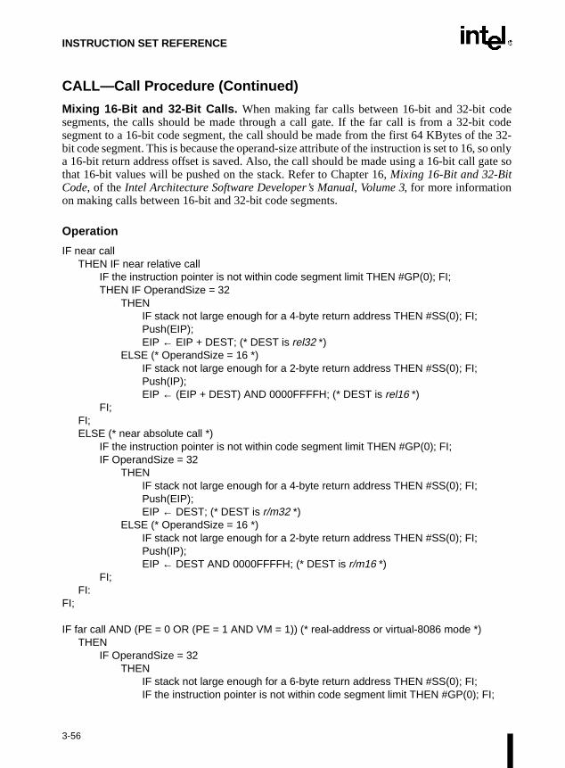
INSTRUCTION SET REFERENCE
CALL—Call Procedure (Continued)
Mixing 16-Bit and 32-Bit Calls. When making far calls between 16-bit and 32-bit codesegments, the calls should be made through a call gate. If the far call is from a 32-bit codesegment to a 16-bit code segment, the call should be made from the first 64 KBytes of the 32-bit code segment. This is because the operand-size attribute of the instruction is set to 16, so onlya 16-bit return address offset is saved. Also, the call should be made using a 16-bit call gate sothat 16-bit values will be pushed on the stack. Refer to Chapter 16, Mixing 16-Bit and 32-BitCode, of the Intel Architecture Software Developer’s Manual, Volume 3, for more informationon making calls between 16-bit and 32-bit code segments.
Operation
IF near callTHEN IF near relative call
IF the instruction pointer is not within code segment limit THEN #GP(0); FI;THEN IF OperandSize = 32
THENIF stack not large enough for a 4-byte return address THEN #SS(0); FI;Push(EIP);EIP ← EIP + DEST; (* DEST is rel32 *)
ELSE (* OperandSize = 16 *)IF stack not large enough for a 2-byte return address THEN #SS(0); FI;Push(IP);EIP ← (EIP + DEST) AND 0000FFFFH; (* DEST is rel16 *)
FI; FI;ELSE (* near absolute call *)
IF the instruction pointer is not within code segment limit THEN #GP(0); FI;IF OperandSize = 32
THENIF stack not large enough for a 4-byte return address THEN #SS(0); FI;Push(EIP); EIP ← DEST; (* DEST is r/m32 *)
ELSE (* OperandSize = 16 *) IF stack not large enough for a 2-byte return address THEN #SS(0); FI;Push(IP);EIP ← DEST AND 0000FFFFH; (* DEST is r/m16 *)
FI; FI:
FI;
IF far call AND (PE = 0 OR (PE = 1 AND VM = 1)) (* real-address or virtual-8086 mode *)THEN
IF OperandSize = 32THEN
IF stack not large enough for a 6-byte return address THEN #SS(0); FI;IF the instruction pointer is not within code segment limit THEN #GP(0); FI;
3-56

INSTRUCTION SET REFERENCE
CALL—Call Procedure (Continued)
Push(CS); (* padded with 16 high-order bits *)Push(EIP);CS ← DEST[47:32]; (* DEST is ptr16:32 or [m16:32] *)EIP ← DEST[31:0]; (* DEST is ptr16:32 or [m16:32] *)
ELSE (* OperandSize = 16 *)IF stack not large enough for a 4-byte return address THEN #SS(0); FI;IF the instruction pointer is not within code segment limit THEN #GP(0); FI;Push(CS);Push(IP);CS ← DEST[31:16]; (* DEST is ptr16:16 or [m16:16] *)EIP ← DEST[15:0]; (* DEST is ptr16:16 or [m16:16] *)EIP ← EIP AND 0000FFFFH; (* clear upper 16 bits *)
FI;FI;
IF far call AND (PE = 1 AND VM = 0) (* Protected mode, not virtual-8086 mode *)THEN
IF segment selector in target operand null THEN #GP(0); FI;IF segment selector index not within descriptor table limits
THEN #GP(new code segment selector);FI;Read type and access rights of selected segment descriptor;IF segment type is not a conforming or nonconforming code segment, call gate,
task gate, or TSS THEN #GP(segment selector); FI;Depending on type and access rights
GO TO CONFORMING-CODE-SEGMENT;GO TO NONCONFORMING-CODE-SEGMENT;GO TO CALL-GATE;GO TO TASK-GATE;GO TO TASK-STATE-SEGMENT;
FI;
CONFORMING-CODE-SEGMENT:IF DPL > CPL THEN #GP(new code segment selector); FI;IF segment not present THEN #NP(new code segment selector); FI;IF OperandSize = 32
THENIF stack not large enough for a 6-byte return address THEN #SS(0); FI;IF the instruction pointer is not within code segment limit THEN #GP(0); FI;Push(CS); (* padded with 16 high-order bits *)Push(EIP);CS ← DEST(NewCodeSegmentSelector); (* segment descriptor information also loaded *)CS(RPL) ← CPLEIP ← DEST(offset);
3-57

INSTRUCTION SET REFERENCE
CALL—Call Procedure (Continued)
ELSE (* OperandSize = 16 *)IF stack not large enough for a 4-byte return address THEN #SS(0); FI;IF the instruction pointer is not within code segment limit THEN #GP(0); FI;Push(CS);Push(IP);CS ← DEST(NewCodeSegmentSelector); (* segment descriptor information also loaded *)CS(RPL) ← CPLEIP ← DEST(offset) AND 0000FFFFH; (* clear upper 16 bits *)
FI;END;
NONCONFORMING-CODE-SEGMENT:IF (RPL > CPL) OR (DPL ≠ CPL) THEN #GP(new code segment selector); FI;IF segment not present THEN #NP(new code segment selector); FI;IF stack not large enough for return address THEN #SS(0); FI;tempEIP ← DEST(offset)IF OperandSize=16
THENtempEIP ← tempEIP AND 0000FFFFH; (* clear upper 16 bits *)
FI;IF tempEIP outside code segment limit THEN #GP(0); FI;IF OperandSize = 32
THENPush(CS); (* padded with 16 high-order bits *)Push(EIP);CS ← DEST(NewCodeSegmentSelector); (* segment descriptor information also loaded *)CS(RPL) ← CPL;EIP ← tempEIP;
ELSE (* OperandSize = 16 *)Push(CS);Push(IP);CS ← DEST(NewCodeSegmentSelector); (* segment descriptor information also loaded *)CS(RPL) ← CPL;EIP ← tempEIP;
FI;END;
CALL-GATE:IF call gate DPL < CPL or RPL THEN #GP(call gate selector); FI;IF call gate not present THEN #NP(call gate selector); FI;IF call gate code-segment selector is null THEN #GP(0); FI;
3-58
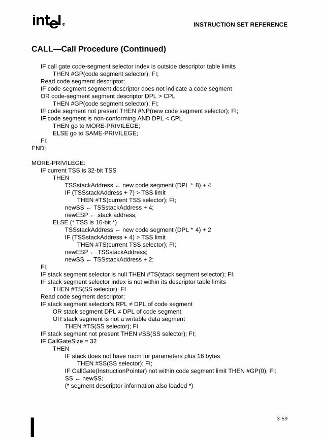
INSTRUCTION SET REFERENCE
CALL—Call Procedure (Continued)
IF call gate code-segment selector index is outside descriptor table limitsTHEN #GP(code segment selector); FI;
Read code segment descriptor;IF code-segment segment descriptor does not indicate a code segmentOR code-segment segment descriptor DPL > CPL
THEN #GP(code segment selector); FI;IF code segment not present THEN #NP(new code segment selector); FI;IF code segment is non-conforming AND DPL < CPL
THEN go to MORE-PRIVILEGE;ELSE go to SAME-PRIVILEGE;
FI;END;
MORE-PRIVILEGE:IF current TSS is 32-bit TSS
THEN TSSstackAddress ← new code segment (DPL ∗ 8) + 4IF (TSSstackAddress + 7) > TSS limit
THEN #TS(current TSS selector); FI;newSS ← TSSstackAddress + 4;newESP ← stack address;
ELSE (* TSS is 16-bit *)TSSstackAddress ← new code segment (DPL ∗ 4) + 2IF (TSSstackAddress + 4) > TSS limit
THEN #TS(current TSS selector); FI;newESP ← TSSstackAddress;newSS ← TSSstackAddress + 2;
FI;IF stack segment selector is null THEN #TS(stack segment selector); FI;IF stack segment selector index is not within its descriptor table limits
THEN #TS(SS selector); FIRead code segment descriptor;IF stack segment selector’s RPL ≠ DPL of code segment
OR stack segment DPL ≠ DPL of code segment OR stack segment is not a writable data segment
THEN #TS(SS selector); FIIF stack segment not present THEN #SS(SS selector); FI;IF CallGateSize = 32
THENIF stack does not have room for parameters plus 16 bytes
THEN #SS(SS selector); FI;IF CallGate(InstructionPointer) not within code segment limit THEN #GP(0); FI;SS ← newSS; (* segment descriptor information also loaded *)
3-59

INSTRUCTION SET REFERENCE
CALL—Call Procedure (Continued)
ESP ← newESP; CS:EIP ← CallGate(CS:InstructionPointer); (* segment descriptor information also loaded *)Push(oldSS:oldESP); (* from calling procedure *)temp ← parameter count from call gate, masked to 5 bits;Push(parameters from calling procedure’s stack, temp)Push(oldCS:oldEIP); (* return address to calling procedure *)
ELSE (* CallGateSize = 16 *)IF stack does not have room for parameters plus 8 bytes
THEN #SS(SS selector); FI;IF (CallGate(InstructionPointer) AND FFFFH) not within code segment limit
THEN #GP(0); FI;SS ← newSS; (* segment descriptor information also loaded *)ESP ← newESP; CS:IP ← CallGate(CS:InstructionPointer);(* segment descriptor information also loaded *)Push(oldSS:oldESP); (* from calling procedure *)temp ← parameter count from call gate, masked to 5 bits;Push(parameters from calling procedure’s stack, temp)Push(oldCS:oldEIP); (* return address to calling procedure *)
FI;CPL ← CodeSegment(DPL)CS(RPL) ← CPL
END;
SAME-PRIVILEGE:IF CallGateSize = 32
THENIF stack does not have room for 8 bytes
THEN #SS(0); FI;IF EIP not within code segment limit then #GP(0); FI;CS:EIP ← CallGate(CS:EIP) (* segment descriptor information also loaded *)Push(oldCS:oldEIP); (* return address to calling procedure *)
ELSE (* CallGateSize = 16 *)IF stack does not have room for parameters plus 4 bytes
THEN #SS(0); FI;IF IP not within code segment limit THEN #GP(0); FI;CS:IP ← CallGate(CS:instruction pointer) (* segment descriptor information also loaded *)Push(oldCS:oldIP); (* return address to calling procedure *)
FI;CS(RPL) ← CPL
END;
3-60

INSTRUCTION SET REFERENCE
CALL—Call Procedure (Continued)
TASK-GATE:IF task gate DPL < CPL or RPL
THEN #GP(task gate selector); FI;IF task gate not present
THEN #NP(task gate selector); FI;Read the TSS segment selector in the task-gate descriptor;IF TSS segment selector local/global bit is set to local
OR index not within GDT limitsTHEN #GP(TSS selector);
FI;Access TSS descriptor in GDT;
IF TSS descriptor specifies that the TSS is busy (low-order 5 bits set to 00001)THEN #GP(TSS selector);
FI;IF TSS not present
THEN #NP(TSS selector);FI;SWITCH-TASKS (with nesting) to TSS;IF EIP not within code segment limit
THEN #GP(0); FI;
END;
TASK-STATE-SEGMENT:IF TSS DPL < CPL or RPLOR TSS descriptor indicates TSS not available
THEN #GP(TSS selector);FI;IF TSS is not present
THEN #NP(TSS selector); FI;SWITCH-TASKS (with nesting) to TSSIF EIP not within code segment limit
THEN #GP(0); FI;
END;
Flags Affected
All flags are affected if a task switch occurs; no flags are affected if a task switch does not occur.
3-61

INSTRUCTION SET REFERENCE
lessment
s not
able
the
able.
r ontowitch
it.
r ontowitch
CALL—Call Procedure (Continued)
Protected Mode Exceptions
#GP(0) If target offset in destination operand is beyond the new code segmentlimit.
If the segment selector in the destination operand is null.
If the code segment selector in the gate is null.
If a memory operand effective address is outside the CS, DS, ES, FS, orGS segment limit.
If the DS, ES, FS, or GS register is used to access memory and it containsa null segment selector.
#GP(selector) If code segment or gate or TSS selector index is outside descriptor tablelimits.
If the segment descriptor pointed to by the segment selector in thedestination operand is not for a conforming-code segment, noncon-forming-code segment, call gate, task gate, or task state segment.
If the DPL for a nonconforming-code segment is not equal to the CPL orthe RPL for the segment’s segment selector is greater than the CPL.
If the DPL for a conforming-code segment is greater than the CPL.
If the DPL from a call-gate, task-gate, or TSS segment descriptor is than the CPL or than the RPL of the call-gate, task-gate, or TSS’s segselector.
If the segment descriptor for a segment selector from a call gate doeindicate it is a code segment.
If the segment selector from a call gate is beyond the descriptor tlimits.
If the DPL for a code-segment obtained from a call gate is greater thanCPL.
If the segment selector for a TSS has its local/global bit set for local.
If a TSS segment descriptor specifies that the TSS is busy or not avail
#SS(0) If pushing the return address, parameters, or stack segment pointethe stack exceeds the bounds of the stack segment, when no stack soccurs.
If a memory operand effective address is outside the SS segment lim
#SS(selector) If pushing the return address, parameters, or stack segment pointethe stack exceeds the bounds of the stack segment, when a stack soccurs.
3-62

INSTRUCTION SET REFERENCE
CALL—Call Procedure (Continued)
If the SS register is being loaded as part of a stack switch and the segmentpointed to is marked not present.
If stack segment does not have room for the return address, parameters, orstack segment pointer, when stack switch occurs.
#NP(selector) If a code segment, data segment, stack segment, call gate, task gate, orTSS is not present.
#TS(selector) If the new stack segment selector and ESP are beyond the end of the TSS.
If the new stack segment selector is null.
If the RPL of the new stack segment selector in the TSS is not equal to theDPL of the code segment being accessed.
If DPL of the stack segment descriptor for the new stack segment is notequal to the DPL of the code segment descriptor.
If the new stack segment is not a writable data segment.
If segment-selector index for stack segment is outside descriptor tablelimits.
#PF(fault-code) If a page fault occurs.
#AC(0) If an unaligned memory access occurs when the CPL is 3 and alignmentchecking is enabled.
Real-Address Mode Exceptions
#GP If a memory operand effective address is outside the CS, DS, ES, FS, orGS segment limit.
If the target offset is beyond the code segment limit.
Virtual-8086 Mode Exceptions
#GP(0) If a memory operand effective address is outside the CS, DS, ES, FS, orGS segment limit.
If the target offset is beyond the code segment limit.
#PF(fault-code) If a page fault occurs.
#AC(0) If an unaligned memory access occurs when alignment checking isenabled.
3-63

INSTRUCTION SET REFERENCE
CBW/CWDE—Convert Byte to Word/Convert Word to Doubleword
Description
These instructions double the size of the source operand by means of sign extension (refer toFigure 6-5 in Chapter 6, Instruction Set Summary of the Intel Architecture Software Developer’sManual, Volume 1). The CBW (convert byte to word) instruction copies the sign (bit 7) in thesource operand into every bit in the AH register. The CWDE (convert word to doubleword)instruction copies the sign (bit 15) of the word in the AX register into the higher 16 bits of theEAX register.
The CBW and CWDE mnemonics reference the same opcode. The CBW instruction is intendedfor use when the operand-size attribute is 16 and the CWDE instruction for when the operand-size attribute is 32. Some assemblers may force the operand size to 16 when CBW is used andto 32 when CWDE is used. Others may treat these mnemonics as synonyms (CBW/CWDE) anduse the current setting of the operand-size attribute to determine the size of values to beconverted, regardless of the mnemonic used.
The CWDE instruction is different from the CWD (convert word to double) instruction. TheCWD instruction uses the DX:AX register pair as a destination operand; whereas, the CWDEinstruction uses the EAX register as a destination.
Operation
IF OperandSize = 16 (* instruction = CBW *)THEN AX ← SignExtend(AL);ELSE (* OperandSize = 32, instruction = CWDE *)
EAX ← SignExtend(AX);FI;
Flags Affected
None.
Exceptions (All Operating Modes)
None.
Opcode Instruction Description
98 CBW AX ← sign-extend of AL
98 CWDE EAX ← sign-extend of AX
3-64

INSTRUCTION SET REFERENCE
ad-
CDQ—Convert Double to Quad
Refer to entry for CWD/CDQ — Convert Word to Doubleword/Convert Doubleword to Quword.
3-65

INSTRUCTION SET REFERENCE
CLC—Clear Carry Flag
Description
This instruction clears the CF flag in the EFLAGS register.
Operation
CF ← 0;
Flags Affected
The CF flag is cleared to 0. The OF, ZF, SF, AF, and PF flags are unaffected.
Exceptions (All Operating Modes)
None.
Opcode Instruction Description
F8 CLC Clear CF flag
3-66

INSTRUCTION SET REFERENCE
CLD—Clear Direction Flag
Description
This instruction clears the DF flag in the EFLAGS register. When the DF flag is set to 0, stringoperations increment the index registers (ESI and/or EDI).
Operation
DF ← 0;
Flags Affected
The DF flag is cleared to 0. The CF, OF, ZF, SF, AF, and PF flags are unaffected.
Exceptions (All Operating Modes)
None.
Opcode Instruction Description
FC CLD Clear DF flag
3-67
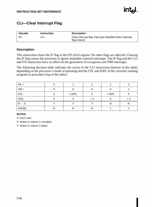
INSTRUCTION SET REFERENCE
nning
CLI—Clear Interrupt Flag
Description
This instruction clears the IF flag in the EFLAGS register. No other flags are affected. Clearingthe IF flag causes the processor to ignore maskable external interrupts. The IF flag and the CLIand STI instruction have no affect on the generation of exceptions and NMI interrupts.
The following decision table indicates the action of the CLI instruction (bottom of the table)depending on the processor’s mode of operating and the CPL and IOPL of the currently ruprogram or procedure (top of the table).
NOTES:
X Don’t care
N Action in column 1 not taken
Y Action in column 1 taken
Opcode Instruction Description
FA CLI Clear interrupt flag; interrupts disabled when interrupt flag cleared
PE = 0 1 1 1 1
VM = X 0 X 0 1
CPL X ≤ IOPL X > IOPL X
IOPL X X = 3 X < 3
IF ← 0 Y Y Y N N
#GP(0) N N N Y Y
3-68
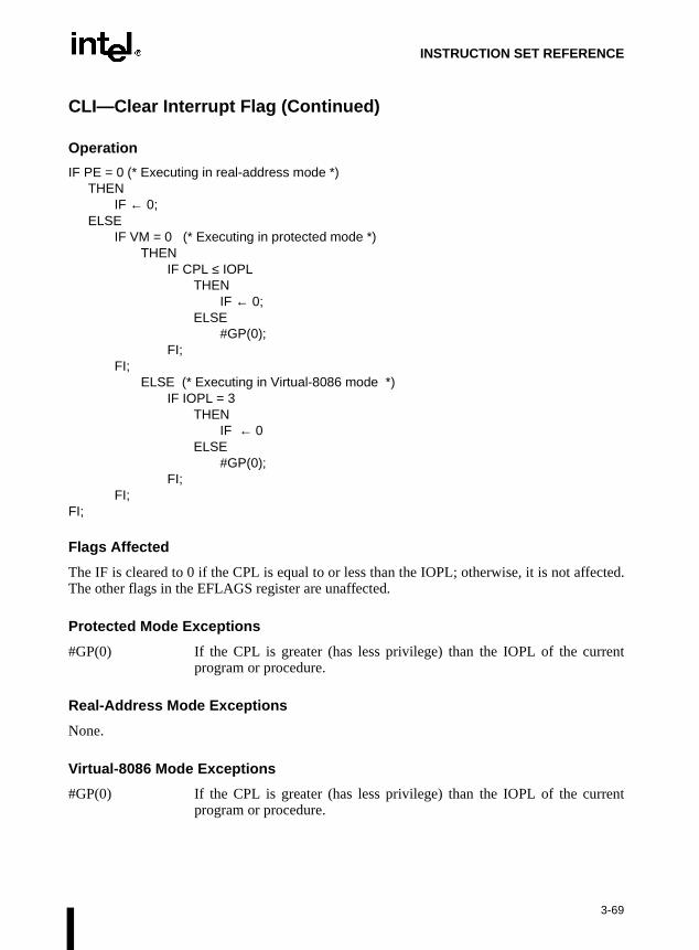
INSTRUCTION SET REFERENCE
CLI—Clear Interrupt Flag (Continued)
Operation
IF PE = 0 (* Executing in real-address mode *)THEN
IF ← 0; ELSE
IF VM = 0 (* Executing in protected mode *)THEN
IF CPL ≤ IOPLTHEN
IF ← 0; ELSE
#GP(0);FI;
FI;ELSE (* Executing in Virtual-8086 mode *)
IF IOPL = 3THEN
IF ← 0ELSE
#GP(0);FI;
FI;FI;
Flags Affected
The IF is cleared to 0 if the CPL is equal to or less than the IOPL; otherwise, it is not affected.The other flags in the EFLAGS register are unaffected.
Protected Mode Exceptions
#GP(0) If the CPL is greater (has less privilege) than the IOPL of the currentprogram or procedure.
Real-Address Mode Exceptions
None.
Virtual-8086 Mode Exceptions
#GP(0) If the CPL is greater (has less privilege) than the IOPL of the currentprogram or procedure.
3-69

INSTRUCTION SET REFERENCE
CLTS—Clear Task-Switched Flag in CR0
Description
This instruction clears the task-switched (TS) flag in the CR0 register. This instruction isintended for use in operating-system procedures. It is a privileged instruction that can only beexecuted at a CPL of 0. It is allowed to be executed in real-address mode to allow initializationfor protected mode.
The processor sets the TS flag every time a task switch occurs. The flag is used to synchronizethe saving of FPU context in multitasking applications. Refer to the description of the TS flagin Section 2.5., Control Registers in Chapter 2, System Architecture Overview of the Intel Archi-tecture Software Developer’s Manual, Volume 3, for more information about this flag.
Operation
CR0(TS) ← 0;
Flags Affected
The TS flag in CR0 register is cleared.
Protected Mode Exceptions
#GP(0) If the CPL is greater than 0.
Real-Address Mode Exceptions
None.
Virtual-8086 Mode Exceptions
#GP(0) If the CPL is greater than 0.
Opcode Instruction Description
0F 06 CLTS Clears TS flag in CR0
3-70

INSTRUCTION SET REFERENCE
CMC—Complement Carry Flag
Description
This instruction complements the CF flag in the EFLAGS register.
Operation
CF ← NOT CF;
Flags Affected
The CF flag contains the complement of its original value. The OF, ZF, SF, AF, and PF flags areunaffected.
Exceptions (All Operating Modes)
None.
Opcode Instruction Description
F5 CMC Complement CF flag
3-71

INSTRUCTION SET REFERENCE
CMOVcc—Conditional Move
Opcode Instruction Description
0F 47 /r CMOVA r16, r/m16 Move if above (CF=0 and ZF=0)
0F 47 /r CMOVA r32, r/m32 Move if above (CF=0 and ZF=0)
0F 43 /r CMOVAE r16, r/m16 Move if above or equal (CF=0)
0F 43 /r CMOVAE r32, r/m32 Move if above or equal (CF=0)
0F 42 /r CMOVB r16, r/m16 Move if below (CF=1)
0F 42 /r CMOVB r32, r/m32 Move if below (CF=1)
0F 46 /r CMOVBE r16, r/m16 Move if below or equal (CF=1 or ZF=1)
0F 46 /r CMOVBE r32, r/m32 Move if below or equal (CF=1 or ZF=1)
0F 42 /r CMOVC r16, r/m16 Move if carry (CF=1)
0F 42 /r CMOVC r32, r/m32 Move if carry (CF=1)
0F 44 /r CMOVE r16, r/m16 Move if equal (ZF=1)
0F 44 /r CMOVE r32, r/m32 Move if equal (ZF=1)
0F 4F /r CMOVG r16, r/m16 Move if greater (ZF=0 and SF=OF)
0F 4F /r CMOVG r32, r/m32 Move if greater (ZF=0 and SF=OF)
0F 4D /r CMOVGE r16, r/m16 Move if greater or equal (SF=OF)
0F 4D /r CMOVGE r32, r/m32 Move if greater or equal (SF=OF)
0F 4C /r CMOVL r16, r/m16 Move if less (SF<>OF)
0F 4C /r CMOVL r32, r/m32 Move if less (SF<>OF)
0F 4E /r CMOVLE r16, r/m16 Move if less or equal (ZF=1 or SF<>OF)
0F 4E /r CMOVLE r32, r/m32 Move if less or equal (ZF=1 or SF<>OF)
0F 46 /r CMOVNA r16, r/m16 Move if not above (CF=1 or ZF=1)
0F 46 /r CMOVNA r32, r/m32 Move if not above (CF=1 or ZF=1)
0F 42 /r CMOVNAE r16, r/m16 Move if not above or equal (CF=1)
0F 42 /r CMOVNAE r32, r/m32 Move if not above or equal (CF=1)
0F 43 /r CMOVNB r16, r/m16 Move if not below (CF=0)
0F 43 /r CMOVNB r32, r/m32 Move if not below (CF=0)
0F 47 /r CMOVNBE r16, r/m16 Move if not below or equal (CF=0 and ZF=0)
0F 47 /r CMOVNBE r32, r/m32 Move if not below or equal (CF=0 and ZF=0)
0F 43 /r CMOVNC r16, r/m16 Move if not carry (CF=0)
0F 43 /r CMOVNC r32, r/m32 Move if not carry (CF=0)
0F 45 /r CMOVNE r16, r/m16 Move if not equal (ZF=0)
0F 45 /r CMOVNE r32, r/m32 Move if not equal (ZF=0)
0F 4E /r CMOVNG r16, r/m16 Move if not greater (ZF=1 or SF<>OF)
0F 4E /r CMOVNG r32, r/m32 Move if not greater (ZF=1 or SF<>OF)
0F 4C /r CMOVNGE r16, r/m16 Move if not greater or equal (SF<>OF)
0F 4C /r CMOVNGE r32, r/m32 Move if not greater or equal (SF<>OF)
0F 4D /r CMOVNL r16, r/m16 Move if not less (SF=OF)
0F 4D /r CMOVNL r32, r/m32 Move if not less (SF=OF)
0F 4F /r CMOVNLE r16, r/m16 Move if not less or equal (ZF=0 and SF=OF)
0F 4F /r CMOVNLE r32, r/m32 Move if not less or equal (ZF=0 and SF=OF)
3-72

INSTRUCTION SET REFERENCE
terms
ys, twove if are
CMOVcc—Conditional Move (Continued)
Description
The CMOVcc instructions check the state of one or more of the status flags in the EFLAGSregister (CF, OF, PF, SF, and ZF) and perform a move operation if the flags are in a specifiedstate (or condition). A condition code (cc) is associated with each instruction to indicate thecondition being tested for. If the condition is not satisfied, a move is not performed and execu-tion continues with the instruction following the CMOVcc instruction.
These instructions can move a 16- or 32-bit value from memory to a general-purpose register orfrom one general-purpose register to another. Conditional moves of 8-bit register operands arenot supported.
The conditions for each CMOVcc mnemonic is given in the description column of the abovetable. The terms “less” and “greater” are used for comparisons of signed integers and the“above” and “below” are used for unsigned integers.
Because a particular state of the status flags can sometimes be interpreted in two wamnemonics are defined for some opcodes. For example, the CMOVA (conditional moabove) instruction and the CMOVNBE (conditional move if not below or equal) instructionalternate mnemonics for the opcode 0F 47H.
Opcode Instruction Description
0F 41 /r CMOVNO r16, r/m16 Move if not overflow (OF=0)
0F 41 /r CMOVNO r32, r/m32 Move if not overflow (OF=0)
0F 4B /r CMOVNP r16, r/m16 Move if not parity (PF=0)
0F 4B /r CMOVNP r32, r/m32 Move if not parity (PF=0)
0F 49 /r CMOVNS r16, r/m16 Move if not sign (SF=0)
0F 49 /r CMOVNS r32, r/m32 Move if not sign (SF=0)
0F 45 /r CMOVNZ r16, r/m16 Move if not zero (ZF=0)
0F 45 /r CMOVNZ r32, r/m32 Move if not zero (ZF=0)
0F 40 /r CMOVO r16, r/m16 Move if overflow (OF=0)
0F 40 /r CMOVO r32, r/m32 Move if overflow (OF=0)
0F 4A /r CMOVP r16, r/m16 Move if parity (PF=1)
0F 4A /r CMOVP r32, r/m32 Move if parity (PF=1)
0F 4A /r CMOVPE r16, r/m16 Move if parity even (PF=1)
0F 4A /r CMOVPE r32, r/m32 Move if parity even (PF=1)
0F 4B /r CMOVPO r16, r/m16 Move if parity odd (PF=0)
0F 4B /r CMOVPO r32, r/m32 Move if parity odd (PF=0)
0F 48 /r CMOVS r16, r/m16 Move if sign (SF=1)
0F 48 /r CMOVS r32, r/m32 Move if sign (SF=1)
0F 44 /r CMOVZ r16, r/m16 Move if zero (ZF=1)
0F 44 /r CMOVZ r32, r/m32 Move if zero (ZF=1)
3-73

INSTRUCTION SET REFERENCE
UID this
S, or
it.
ce is
S, or
it.
CMOVcc—Conditional Move (Continued)
The CMOVcc instructions are new for the Pentium® Pro processor family; however, they maynot be supported by all the processors in the family. Software can determine if the CMOVccinstructions are supported by checking the processor’s feature information with the CPinstruction (refer to “COMISS—Scalar Ordered Single-FP Compare and Set EFLAGS” inchapter).
Operation
temp ← DESTIF condition TRUE
THENDEST ← SRC
ELSEDEST ← temp
FI;
Flags Affected
None.
Protected Mode Exceptions
#GP(0) If a memory operand effective address is outside the CS, DS, ES, FGS segment limit.
If the DS, ES, FS, or GS register contains a null segment selector.
#SS(0) If a memory operand effective address is outside the SS segment lim
#PF(fault-code) If a page fault occurs.
#AC(0) If alignment checking is enabled and an unaligned memory referenmade while the current privilege level is 3.
Real-Address Mode Exceptions
#GP If a memory operand effective address is outside the CS, DS, ES, FGS segment limit.
#SS If a memory operand effective address is outside the SS segment lim
3-74

INSTRUCTION SET REFERENCE
CMOVcc—Conditional Move (Continued)
Virtual-8086 Mode Exceptions
#GP(0) If a memory operand effective address is outside the CS, DS, ES, FS, orGS segment limit.
#SS(0) If a memory operand effective address is outside the SS segment limit.
#PF(fault-code) If a page fault occurs.
#AC(0) If alignment checking is enabled and an unaligned memory reference ismade.
3-75

INSTRUCTION SET REFERENCE
CMP—Compare Two Operands
Description
This instruction compares the first source operand with the second source operand and sets thestatus flags in the EFLAGS register according to the results. The comparison is performed bysubtracting the second operand from the first operand and then setting the status flags in thesame manner as the SUB instruction. When an immediate value is used as an operand, it is sign-extended to the length of the first operand.
The CMP instruction is typically used in conjunction with a conditional jump (Jcc), conditionmove (CMOVcc), or SETcc instruction. The condition codes used by the Jcc, CMOVcc, andSETcc instructions are based on the results of a CMP instruction. Appendix B, EFLAGS Condi-tion Codes, in the Intel Architecture Software Developer’s Manual, Volume 1, shows the rela-tionship of the status flags and the condition codes.
Operation
temp ← SRC1 − SignExtend(SRC2); ModifyStatusFlags; (* Modify status flags in the same manner as the SUB instruction*)
Flags Affected
The CF, OF, SF, ZF, AF, and PF flags are set according to the result.
Opcode Instruction Description
3C ib CMP AL, imm8 Compare imm8 with AL
3D iw CMP AX, imm16 Compare imm16 with AX
3D id CMP EAX, imm32 Compare imm32 with EAX
80 /7 ib CMP r/m8, imm8 Compare imm8 with r/m8
81 /7 iw CMP r/m16, imm16 Compare imm16 with r/m16
81 /7 id CMP r/m32,imm32 Compare imm32 with r/m32
83 /7 ib CMP r/m16,imm8 Compare imm8 with r/m16
83 /7 ib CMP r/m32,imm8 Compare imm8 with r/m32
38 /r CMP r/m8,r8 Compare r8 with r/m8
39 /r CMP r/m16,r16 Compare r16 with r/m16
39 /r CMP r/m32,r32 Compare r32 with r/m32
3A /r CMP r8,r/m8 Compare r/m8 with r8
3B /r CMP r16,r/m16 Compare r/m16 with r16
3B /r CMP r32,r/m32 Compare r/m32 with r32
3-76

INSTRUCTION SET REFERENCE
CMP—Compare Two Operands (Continued)
Protected Mode Exceptions
#GP(0) If a memory operand effective address is outside the CS, DS, ES, FS, orGS segment limit.
If the DS, ES, FS, or GS register contains a null segment selector.
#SS(0) If a memory operand effective address is outside the SS segment limit.
#PF(fault-code) If a page fault occurs.
#AC(0) If alignment checking is enabled and an unaligned memory reference ismade while the current privilege level is 3.
Real-Address Mode Exceptions
#GP If a memory operand effective address is outside the CS, DS, ES, FS, orGS segment limit.
#SS If a memory operand effective address is outside the SS segment limit.
Virtual-8086 Mode Exceptions
#GP(0) If a memory operand effective address is outside the CS, DS, ES, FS, orGS segment limit.
#SS(0) If a memory operand effective address is outside the SS segment limit.
#PF(fault-code) If a page fault occurs.
#AC(0) If alignment checking is enabled and an unaligned memory reference ismade.
3-77

INSTRUCTION SET REFERENCE
CMPPS—Packed Single-FP Compare
Description
For each individual pair of SP FP numbers, the CMPPS instruction returns an all "1" 32-bit maskor an all "0" 32-bit mask, using the comparison predicate specified by imm8.
Figure 3-8. Operation of the CMPPS (Imm8=1) Instruction
Opcode Instruction Description
0F,C2,/r,ib CMPPS xmm1, xmm2/m128, imm8
Compare packed SP FP numbers from XMM2/Mem to packed SP FP numbers in XMM1 register using imm8 as predicate.
Figure 3-7. Operation of the CMPPS (Imm8=0) Instruction
True False FalseTrue
== == ==Xmm1
Xmm2/m128
Xmm1
10.0
00000000 11111111 0000000011111111
9.0
CMPPS xmm1, xmm2/m128, imm8 (imm8=0)
10.0 2.0
Xmm1
Xmm2/m128
CMPPS xmm1, xmm2/m128,imm8 (Imm8=1)
3.0
10.0
True TrueFalse False
11.0 9.0 4.0
2.0 9.0 1.0
< < < <
0000000000000000 11111111 11111111
Xmm1
3-78

INSTRUCTION SET REFERENCE
CMPPS—Packed Single-FP Compare (Continued)
Figure 3-9. Operation of the CMPPS (Imm8=2) Instruction
Figure 3-10. Operation of the CMPPS (Imm8=3) Instruction
False True TrueTrue
<= <= <=Xmm1
Xmm2/m128
Xmm1
3.0
00000000 11111111 1111111111111111
9.0
CMPPS xmm1, xmm2/m128, imm8 (imm8=2)
10.0 2.0
Xmm1
Xmm2/m128
CMPPS xmm1, xmm2/m128,imm8 (Imm8=3)
3.0
10.0
True TrueFalse False
11.0 9.0 QNaN
QNaN 9.0 1.0
? ? ? ?
0000000000000000 11111111 11111111
Xmm1
3-79

INSTRUCTION SET REFERENCE
CMPPS—Packed Single-FP Compare (Continued)
Figure 3-11. Operation of the CMPPS (Imm8=4) Instruction
Figure 3-12. Operation of the CMPPS (Imm8=5) Instruction
FalseTrue TrueTrue
!= != !=Xmm1
Xmm2/m128
Xmm1
3.0
00000000 11111111 1111111111111111
9.0
CMPPS xmm1, xmm2/m128, imm8 (imm8=4)
10.0 2.0
Xmm1
Xmm2/m128
CMPPS xmm1, xmm2/m128,imm8 (Imm8=5)
3.0
10.0
True TrueFalse False
11.0 9.0 4.0
2.0 9.0 1.0
!< !<
000000000000000011111111 11111111
Xmm1
3-80

INSTRUCTION SET REFERENCE
CMPPS—Packed Single-FP Compare (Continued)
Figure 3-13. Operation of the CMPPS (Imm8=6) Instruction
Figure 3-14. Operation of the CMPPS (Imm8=7) Instruction
False False FalseTrue
!<= !<=Xmm1
Xmm2/m128
Xmm1
3.0
00000000 00000000 00000000 11111111
9.0
CMPPS xmm1, xmm2/m128, imm8 (imm8=6)
10.0 2.0
Xmm1
Xmm2/m128
CMPPS xmm1, xmm2/m128,imm8 (Imm8=7)
3.0
10.0
True TrueFalse False
11.0 9.0 QNaN
QNaN 9.0 1.0
!? !?
000000000000000011111111 11111111
Xmm1
3-81

INSTRUCTION SET REFERENCE
ask ofd onlyerands,nd thenlationsrent
CMPPS—Packed Single-FP Compare (Continued)
Note that a subsequent computational instruction which uses this mask as an input operand willnot generate a fault, since a mask of all "0’s" corresponds to an FP value of +0.0 and a mall "1’s" corresponds to an FP value of -qNaN. Some of the comparisons can be achievethrough software emulation. For these comparisons the programmer must swap the opcopying registers when necessary to protect the data that will now be in the destination, aperform the compare using a different predicate. The predicate to be used for these emuis listed in the table under the heading "Emulation". The following table shows the diffecomparison types:
:
NOTE:
The greater-than, greater-than-or-equal, not-greater-than, and not-greater-than-or-equal relations are notdirectly implemented in hardware.
Predicate Description Relation Emulation imm8 Encoding
Result if NaN
Operand
Q/SNaN OperandSignals Invalid
eq equal xmm1 == xmm2
000B False No
lt less-than xmm1 < xmm2
001B False Yes
le less-than-or-equal xmm1 <= xmm2
010B False Yes
greater than xmm1 > xmm2
swap, protect, lt
False Yes
greater-than-or-equal
xmm1 >= xmm2
swap protect, le
False Yes
unord unordered xmm1 ? xmm2
011B True No
neq not-equal !(xmm1 == xmm2)
100B True No
nlt not-less-than !(xmm1 < xmm2)
101B True Yes
nle not-less-than-or-equal
!(xmm1 <= xmm2)
110B True Yes
not-greater-than !(xmm1 > xmm2)
swap, protect, nlt
True Yes
not-greater-than-or-equal
!(xmm1 >= xmm2)
swap, protect, nle
True Yes
ord ordered !(xmm1 ? xmm2)
111B False No
3-82

INSTRUCTION SET REFERENCE
CMPPS—Packed Single-FP Compare (Continued)
Operation
IF (imm8 = 0) THENOP = "EQ";
ELSEIF (imm8 = 1) THEN
OP = "LT";ELSE
IF (imm8 = 2) THENOP = "LE";
ELSEIF (imm8 = 3) THEN
OP = "UNORD";ELSE
IF (imm8 = 4) THENOP = "NE";
ELSEIF (imm8 = 5) THEN
OP = "NLT";ELSE
IF (imm8 = 6) THENOP = "NLE";
ELSEIF (imm8 = 7) THEN
OP = "ORD";FI
FIFI
FIFI
FIFI
FI
CMP0 = DEST[31-0] OP SRC/m128[31-0];CMP1 = DEST[63-32] OP SRC/m128[63-32];CMP2 = DEST [95-64] OP SRC/m128[95-64];CMP3 = DEST[127-96] OP SRC/m128[127-96];
IF (CMP0 = TRUE) THENDEST[31-0] = 0XFFFFFFFF;DEST[63-32] = 0XFFFFFFFF;DEST[95-64] = 0XFFFFFFFF;DEST[127-96] = 0XFFFFFFFF;
3-83

INSTRUCTION SET REFERENCE
CMPPS—Packed Single-FP Compare (Continued)
ELSEDEST[31-0] = 0X00000000;DEST[63-32] = 0X00000000;DEST[95-64] = 0X00000000;DEST[127-96] = 0X00000000;
FI
Intel C/C++ Compiler Intrinsic Equivalents
__m128 _mm_cmpeq_ps(__m128 a, __m128 b)
Compare for equality.
__m128 _mm_cmplt_ps(__m128 a, __m128 b)
Compare for less-than.
__m128 _mm_cmple_ps(__m128 a, __m128 b)
Compare for less-than-or-equal.
__m128 _mm_cmpgt_ps(__m128 a, __m128 b)
Compare for greater-than.
__m128 _mm_cmpge_ps(__m128 a, __m128 b)
Compare for greater-than-or-equal.
__m128 _mm_cmpneq_ps(__m128 a, __m128 b)
Compare for inequality.
__m128 _mm_cmpnlt_ps(__m128 a, __m128 b)
Compare for not-less-than.
__m128 _mm_cmpngt_ps(__m128 a, __m128 b)
Compare for not-greater-than.
__m128 _mm_cmpnge_ps(__m128 a, __m128 b)
Compare for not-greater-than-or-equal.
__m128 _mm_cmpord_ps(__m128 a, __m128 b)
Compare for ordered.
__m128 _mm_cmpunord_ps(__m128 a, __m128 b)
Compare for unordered.
__m128 _mm_cmpnle_ps(__m128 a, __m128 b)
Compare for not-less-than-or-equal.
3-84

INSTRUCTION SET REFERENCE
CMPPS—Packed Single-FP Compare (Continued)
Exceptions
General protection exception if not aligned on 16-byte boundary, regardless of segment.
Numeric Exceptions
Invalid, if sNaN operands, denormal.
Protected Mode Exceptions
#GP(0) For an illegal memory operand effective address in the CS, DS, ES, FS, orGS segments.
#SS(0) For an illegal address in the SS segment.
#PF(fault-code) For a page fault.
#UD If CR0.EM = 1.
#NM If TS bit in CR0 is set.
#XM For an unmasked Streaming SIMD Extension numeric exception(CR4.OSXMMEXCPT =1).
#UD For an unmasked Streaming SIMD Extension numeric exception(CR4.OSXMMEXCPT =0).
#UD If CR4.OSFXSR(bit 9) = 0.
#UD If CPUID.XMM(EDX bit 25) = 0.
Real Address Mode Exceptions
Interrupt 13 If any part of the operand would lie outside of the effective address spacefrom 0 to 0FFFFH.
#UD If CR0.EM = 1.
#NM If TS bit in CR0 is set.
#XM For an unmasked Streaming SIMD Extension numeric exception(CR4.OSXMMEXCPT =1).
#UD For an unmasked Streaming SIMD Extension numeric exception(CR4.OSXMMEXCPT =0).
#UD If CR4.OSFXSR(bit 9) = 0.
#UD If CPUID.XMM(EDX bit 25) = 0.
3-85

INSTRUCTION SET REFERENCE
CMPPS—Packed Single-FP Compare (Continued)
Virtual Mode Exceptions
Same exceptions as in Real Address Mode.
#PF(fault-code) For a page fault.
Comments
Compilers and assemblers should implement the following 2-operand pseudo-ops in addition tothe 3-operand CMPPS instruction:
The greater-than relations not implemented in hardware require more than one instruction toemulate in software and therefore should not be implemented as pseudo-ops. (For these, theprogrammer should reverse the operands of the corresponding less than relations and use moveinstructions to ensure that the mask is moved to the correct destination register and that thesource operand is left intact.)
Bits 7-4 of the immediate field are reserved. Different processors may handle them differently.Usage of these bits risks incompatibility with future processors.
Pseudo-Op Implementation
CMPEQPS xmm1, xmm2 CMPPS xmm1,xmm2, 0
CMPLTPS xmm1, xmm2 CMPPS xmm1,xmm2, 1
CMPLEPS xmm1, xmm2 CMPPS xmm1,xmm2, 2
CMPUNORDPS xmm1, xmm2 CMPPS xmm1,xmm2, 3
CMPNEQPS xmm1, xmm2 CMPPS xmm1,xmm2, 4
CMPNLTPS xmm1, xmm2 CMPPS xmm1,xmm2, 5
CMPNLEPS xmm1, xmm2 CMPPS xmm1,xmm2, 6
CMPORDPS xmm1, xmm2 CMPPS xmm1,xmm2, 7
3-86

INSTRUCTION SET REFERENCE
nds”PS
erandserandsy this
t :(E)DId.
of thecessored withuble-
CMPS/CMPSB/CMPSW/CMPSD—Compare String Operands
Description
This instruction compares the byte, word, or double word specified with the first source operandwith the byte, word, or double word specified with the second source operand and sets the statusflags in the EFLAGS register according to the results. Both the source operands are located inmemory. The address of the first source operand is read from either the DS:ESI or the DS:SIregisters (depending on the address-size attribute of the instruction, 32 or 16, respectively). Theaddress of the second source operand is read from either the ES:EDI or the ES:DI registers(again depending on the address-size attribute of the instruction). The DS segment may be over-ridden with a segment override prefix, but the ES segment cannot be overridden.
At the assembly-code level, two forms of this instruction are allowed: the “explicit-operaform and the “no-operands” form. The explicit-operands form (specified with the CMmnemonic) allows the two source operands to be specified explicitly. Here, the source opshould be symbols that indicate the size and location of the source values. This explicit-opform is provided to allow documentation; however, note that the documentation provided bform can be misleading. That is, the source operand symbols must specify the correct type (size)of the operands (bytes, words, or doublewords), but they do not have to specify the correcloca-tion. The locations of the source operands are always specified by the DS:(E)SI and ESregisters, which must be loaded correctly before the compare string instruction is execute
The no-operands form provides “short forms” of the byte, word, and doubleword versions CMPS instructions. Here also the DS:(E)SI and ES:(E)DI registers are assumed by the proto specify the location of the source operands. The size of the source operands is selectthe mnemonic: CMPSB (byte comparison), CMPSW (word comparison), or CMPSD (doword comparison).
Opcode Instruction Description
A6 CMPS m8, m8 Compares byte at address DS:(E)SI with byte at address ES:(E)DI and sets the status flags accordingly
A7 CMPS m16, m16 Compares word at address DS:(E)SI with word at address ES:(E)DI and sets the status flags accordingly
A7 CMPS m32, m32 Compares doubleword at address DS:(E)SI with doubleword at address ES:(E)DI and sets the status flags accordingly
A6 CMPSB Compares byte at address DS:(E)SI with byte at address ES:(E)DI and sets the status flags accordingly
A7 CMPSW Compares word at address DS:(E)SI with word at address ES:(E)DI and sets the status flags accordingly
A7 CMPSD Compares doubleword at address DS:(E)SI with doubleword at address ES:(E)DI and sets the status flags accordingly
3-87

INSTRUCTION SET REFERENCE
PNEfix.
CMPS/CMPSB/CMPSW/CMPSD—Compare String Operands (Continued)
After the comparison, the (E)SI and (E)DI registers are incremented or decremented automati-cally according to the setting of the DF flag in the EFLAGS register. (If the DF flag is 0, the(E)SI and (E)DI register are incremented; if the DF flag is 1, the (E)SI and (E)DI registers aredecremented.) The registers are incremented or decremented by one for byte operations, by twofor word operations, or by four for doubleword operations.
The CMPS, CMPSB, CMPSW, and CMPSD instructions can be preceded by the REP prefix forblock comparisons of ECX bytes, words, or doublewords. More often, however, these instruc-tions will be used in a LOOP construct that takes some action based on the setting of the statusflags before the next comparison is made. Refer to “REP/REPE/REPZ/RE/REPNZ—Repeat String Operation Prefix” in this chapter for a description of the REP pre
Operation
temp ←SRC1 − SRC2;SetStatusFlags(temp);IF (byte comparison)
THEN IF DF = 0THEN
(E)SI ← (E)SI + 1; (E)DI ← (E)DI + 1;
ELSE (E)SI ← (E)SI – 1; (E)DI ← (E)DI – 1;
FI;ELSE IF (word comparison)
THEN IF DF = 0(E)SI ← (E)SI + 2; (E)DI ← (E)DI + 2;
ELSE (E)SI ← (E)SI – 2; (E)DI ← (E)DI – 2;
FI;ELSE (* doubleword comparison*)
THEN IF DF = 0(E)SI ← (E)SI + 4; (E)DI ← (E)DI + 4;
ELSE (E)SI ← (E)SI – 4; (E)DI ← (E)DI – 4;
FI;FI;
3-88

INSTRUCTION SET REFERENCE
CMPS/CMPSB/CMPSW/CMPSD—Compare String Operands (Continued)
Flags Affected
The CF, OF, SF, ZF, AF, and PF flags are set according to the temporary result of the comparison.
Protected Mode Exceptions
#GP(0) If a memory operand effective address is outside the CS, DS, ES, FS, orGS segment limit.
If the DS, ES, FS, or GS register contains a null segment selector.
#SS(0) If a memory operand effective address is outside the SS segment limit.
#PF(fault-code) If a page fault occurs.
#AC(0) If alignment checking is enabled and an unaligned memory reference ismade while the current privilege level is 3.
Real-Address Mode Exceptions
#GP If a memory operand effective address is outside the CS, DS, ES, FS, orGS segment limit.
#SS If a memory operand effective address is outside the SS segment limit.
Virtual-8086 Mode Exceptions
#GP(0) If a memory operand effective address is outside the CS, DS, ES, FS, orGS segment limit.
#SS(0) If a memory operand effective address is outside the SS segment limit.
#PF(fault-code) If a page fault occurs.
#AC(0) If alignment checking is enabled and an unaligned memory reference ismade.
3-89

INSTRUCTION SET REFERENCE
valuethosesary toing a
eading
CMPSS—Scalar Single-FP Compare
Description
For the lowest pair of SP FP numbers, the CMPSS instruction returns an all "1" 32-bit mask oran all "0" 32-bit mask, using the comparison predicate specified by imm8. The values for theupper three pairs of SP FP numbers are not compared. Note that a subsequent computationalinstruction, which uses this mask as an input operand, will not generate a fault, since a mask ofall "0"s corresponds to an FP value of +0.0, and a mask of all "1’s" corresponds to an FPof -qNaN. Some comparisons can be achieved only through software emulation. For comparisons, the programmer must swap the operands, copying registers when necesprotect the data that will now be in the destination, and then perform the compare usdifferent predicate. The predicate to be used for these emulations is listed under the h"Emulation."
Opcode Instruction Description
F3,0F,C2,/r,ib CMPSS xmm1, xmm2/m32, imm8
Compare lowest SP FP number from XMM2/Mem to lowest SP FP number in XMM1 register using imm8 as predicate.
3-90

INSTRUCTION SET REFERENCE
CMPSS—Scalar Single-FP Compare (Continued)
The following table shows the different comparison types:
NOTE:
* The greater-than, greater-than-or-equal, not-greater-than, and not-greater-than-or-equal relations are notdirectly implemented in hardware.
Predi-cate
Description Relation Emulation imm8 Encoding
Result if NaN
Operand
qNaN OperandSignals Invalid
eq equal xmm1 == xmm2 000B False No
lt less-than xmm1 < xmm2 001B False Yes
le less-than-or-equal xmm1 <= xmm2 010B False Yes
greater than xmm1 > xmm2 swap, protect, lt
False Yes
greater-than-or-equal xmm1 >= xmm2 swap protect, le
False Yes
unord unordered xmm1 ? xmm2 011B True No
neq not-equal !(xmm1 == xmm2) 100B True No
nlt not-less-than !(xmm1 < xmm2) 101B True Yes
nle not-less-than-or-equal !(xmm1 <= xmm2) 110B True Yes
not-greater-than !(xmm1 > xmm2) swap, protect, nlt
True Yes
not-greater-than-or-equal !(xmm1 >= xmm2) swap, protect, nle
True Yes
ord ordered !(xmm1 ? xmm2) 111B False No
3-91

INSTRUCTION SET REFERENCE
CMPSS—Scalar Single-FP Compare (Continued)
Figure 3-15. Operation of the CMPSS (Imm8=0) Instruction
Figure 3-16. Operation of the CMPSS (Imm8=1) Instruction
False
==Xmm1
Xmm2/m32
Xmm1 00000000
CMPSS xmm1, xmm2/m32, imm8 (imm8=0)
Xmm1
Xmm2/m32
CMPSS xmm1, xmm2/m32,imm8 (Imm8=1)
True
4.0
1.0Xmm1
3-92

INSTRUCTION SET REFERENCE
CMPSS—Scalar Single-FP Compare (Continued)
Figure 3-17. Operation of the CMPSS (Imm8=2) Instruction
Figure 3-18. Operation of the CMPSS (Imm8=3) Instruction
True
<=Xmm1
Xmm2/m32
Xmm1
CMPSS xmm1, xmm2/m32, imm8 (imm8=2)
Xmm1
Xmm2/m32
CMPSS xmm1, xmm2/m32,imm8 (Imm8=3)
True
4.0
QNaNXmm1
3-93
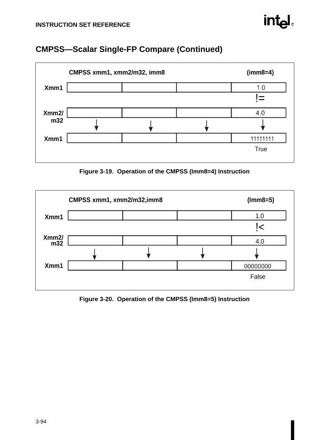
INSTRUCTION SET REFERENCE
CMPSS—Scalar Single-FP Compare (Continued)
Figure 3-19. Operation of the CMPSS (Imm8=4) Instruction
Figure 3-20. Operation of the CMPSS (Imm8=5) Instruction
True
!=Xmm1
Xmm2/m32
Xmm1
CMPSS xmm1, xmm2/m32, imm8 (imm8=4)
Xmm1
Xmm2/m32
CMPSS xmm1, xmm2/m32,imm8 (Imm8=5)
False
4.0
1.0Xmm1
3-94

INSTRUCTION SET REFERENCE
CMPSS—Scalar Single-FP Compare (Continued)
Figure 3-21. Operation of the CMPSS (Imm8=6) Instruction
Figure 3-22. Operation of the CMPSS (Imm8=7) Instruction
False
!<=Xmm1
Xmm2/m32
Xmm1
CMPSS xmm1, xmm2/m32, imm8 (imm8=6)
Xmm1
Xmm2/m32
CMPSS xmm1, xmm2/m32,imm8 (Imm8=7)
False
QNaN
1.0Xmm1
3-95

INSTRUCTION SET REFERENCE
CMPSS—Scalar Single-FP Compare (Continued)
Operation
IF (imm8 = 0) THENOP = "EQ";
ELSEIF (imm8 = 1) THEN
OP = "LT";ELSE
IF (imm8 = 2) THENOP = "LE";
ELSEIF (imm8 = 3) THEN
OP = "UNORD";ELSE
IF (imm8 = 4) THENOP = "NE";
ELSEIF (imm8 = 5) THEN
OP = "NLT";ELSE
IF (imm8 = 6) THENOP = "NLE";
ELSEIF (imm8 = 7) THEN
OP = "ORD";FI
FIFI
FIFI
FIFI
FICMP0 = DEST[31-0] OP SRC/m128[31-0];
IF (CMP0 = TRUE) THENDEST[31-0] = 0XFFFFFFFF;DEST[63-32] = DEST[63-32];DEST[95-64] = DEST[95-64];DEST[127-96] = DEST[127-96];
ELSEDEST[31-0] = 0X00000000;DEST[63-32] = DEST[63-32];DEST[95-64] = DEST[95-64];DEST[127-96] = DEST[127-96];
FI
3-96

INSTRUCTION SET REFERENCE
CMPSS—Scalar Single-FP Compare (Continued)
Intel C/C++ Compiler Intrinsic Equivalents
__m128 _mm_cmpeq_ss(__m128 a, __m128 b)
Compare for equality.
__m128 _mm_cmplt_ss(__m128 a, __m128 b)
Compare for less-than.
__m128 _mm_cmple_ss(__m128 a, __m128 b)
Compare for less-than-or-equal.
__m128 _mm_cmpgt_ss(__m128 a, __m128 b)
Compare for greater-than.
__m128 _mm_cmpge_ss(__m128 a, __m128 b)
Compare for greater-than-or-equal.
__m128 _mm_cmpneq_ss(__m128 a, __m128 b)
Compare for inequality.
__m128 _mm_cmpnlt_ss(__m128 a, __m128 b)
Compare for not-less-than.
__m128 _mm_cmpnle_ss(__m128 a, __m128 b)
Compare for not-less-than-or-equal.
__m128 _mm_cmpngt_ss(__m128 a, __m128 b)
Compare for not-greater-than.
__m128 _mm_cmpnge_ss(__m128 a, __m128 b)
Compare for not-greater-than-or-equal.
__m128 _mm_cmpord_ss(__m128 a, __m128 b)
Compare for ordered.
__m128 _mm_cmpunord_ss(__m128 a, __m128 b)
Compare for unordered.
3-97

INSTRUCTION SET REFERENCE
CMPSS—Scalar Single-FP Compare (Continued)
Exceptions
None.
Numeric Exceptions
Invalid if sNaN operand, invalid if qNaN and predicate as listed in above table, denormal.
Protected Mode Exceptions
#GP(0) For an illegal memory operand effective address in the CS, DS, ES, FS, orGS segments.
#SS(0) For an illegal address in the SS segment.
#PF (fault-code) For a page fault.
#UD If CR0.EM = 1.
#NM If TS bit in CR0 is set.
#AC For unaligned memory reference. To enable #AC exceptions, three condi-tions must be true (CR0.AM is set; EFLAGS.AC is set; current CPL is 3).
#XM For an unmasked Streaming SIMD Extension numeric exception(CR4.OSXMMEXCPT =1).
#UD For an unmasked Streaming SIMD Extension numeric exception(CR4.OSXMMEXCPT =0).
#UD If CR4.OSFXSR(bit 9) = 0.
#UD If CPUID.XMM(EDX bit 25) = 0.
Real Address Mode Exceptions
Interrupt 13 If any part of the operand would lie outside of the effective address spacefrom 0 to 0FFFFH.
#UD If CR0.EM = 1.
#NM If TS bit in CR0 is set.
#XM For an unmasked Streaming SIMD Extension numeric exception(CR4.OSXMMEXCPT =1).
#UD For an unmasked Streaming SIMD Extension numeric exception(CR4.OSXMMEXCPT =0).
#UD If CR4.OSFXSR(bit 9) = 0.
#UD If CPUID.XMM(EDX bit 25) = 0.
3-98

INSTRUCTION SET REFERENCE
CMPSS—Scalar Single-FP Compare (Continued)
Virtual 8086 Mode Exceptions
Same exceptions as in Real Address Mode.
#AC For unaligned memory reference if the current privilege level is 3.
#PF (fault-code) For a page fault.
Comments
Compilers and assemblers should implement the following 2-operand pseudo-ops in addition tothe 3-operand CMPSS instruction.
The greater-than relations not implemented in hardware require more than one instruction toemulate in software and therefore should not be implemented as pseudo-ops. (For these, theprogrammer should reverse the operands of the corresponding less than relations and use moveinstructions to ensure that the mask is moved to the correct destination register and that thesource operand is left intact.)
Bits 7-4 of the immediate field are reserved. Different processors may handle them differently.Usage of these bits risks incompatibility with future processors.
Pseudo-Op Implementation
CMPEQSS xmm1, xmm2 CMPSS xmm1,xmm2, 0
CMPLTSS xmm1, xmm2 CMPSS xmm1,xmm2, 1
CMPLESS xmm1, xmm2 CMPSS xmm1,xmm2, 2
CMPUNORDSS xmm1, xmm2 CMPSS xmm1,xmm2, 3
CMPNEQSS xmm1, xmm2 CMPSS xmm1,xmm2, 4
CMPNLTSS xmm1, xmm2 CMPSS xmm1,xmm2, 5
CMPNLESS xmm1, xmm2 CMPSS xmm1,xmm2, 6
CMPORDSS xmm1, xmm2 CMPSS xmm1,xmm2, 7
3-99

INSTRUCTION SET REFERENCE
writeack if(The
rs.
qual; of the
CMPXCHG—Compare and Exchange
Description
This instruction compares the value in the AL, AX, or EAX register (depending on the size ofthe operand) with the first operand (destination operand). If the two values are equal, the secondoperand (source operand) is loaded into the destination operand. Otherwise, the destinationoperand is loaded into the AL, AX, or EAX register.
This instruction can be used with a LOCK prefix to allow the instruction to be executed atomi-cally. To simplify the interface to the processor’s bus, the destination operand receives acycle without regard to the result of the comparison. The destination operand is written bthe comparison fails; otherwise, the source operand is written into the destination. processor never produces a locked read without also producing a locked write.)
Intel Architecture Compatibility
This instruction is not supported on Intel processors earlier than the Intel486™ processo
Operation
(* accumulator = AL, AX, or EAX, depending on whether *)(* a byte, word, or doubleword comparison is being performed*)IF accumulator = DEST
THENZF ← 1DEST ← SRC
ELSEZF ← 0accumulator ← DEST
FI;
Flags Affected
The ZF flag is set if the values in the destination operand and register AL, AX, or EAX are eotherwise it is cleared. The CF, PF, AF, SF, and OF flags are set according to the resultscomparison operation.
Opcode Instruction Description
0F B0/r CMPXCHG r/m8,r8 Compare AL with r/m8. If equal, ZF is set and r8 is loaded into r/m8. Else, clear ZF and load r/m8 into AL.
0F B1/r CMPXCHG r/m16,r16 Compare AX with r/m16. If equal, ZF is set and r16 is loaded into r/m16. Else, clear ZF and load r/m16 into AL
0F B1/r CMPXCHG r/m32,r32 Compare EAX with r/m32. If equal, ZF is set and r32 is loaded into r/m32. Else, clear ZF and load r/m32 into AL
3-100

INSTRUCTION SET REFERENCE
CMPXCHG—Compare and Exchange (Continued)
Protected Mode Exceptions
#GP(0) If the destination is located in a nonwritable segment.
If a memory operand effective address is outside the CS, DS, ES, FS, orGS segment limit.
If the DS, ES, FS, or GS register contains a null segment selector.
#SS(0) If a memory operand effective address is outside the SS segment limit.
#PF(fault-code) If a page fault occurs.
#AC(0) If alignment checking is enabled and an unaligned memory reference ismade while the current privilege level is 3.
Real-Address Mode Exceptions
#GP If a memory operand effective address is outside the CS, DS, ES, FS, orGS segment limit.
#SS If a memory operand effective address is outside the SS segment limit.
Virtual-8086 Mode Exceptions
#GP(0) If a memory operand effective address is outside the CS, DS, ES, FS, orGS segment limit.
#SS(0) If a memory operand effective address is outside the SS segment limit.
#PF(fault-code) If a page fault occurs.
#AC(0) If alignment checking is enabled and an unaligned memory reference ismade.
3-101

INSTRUCTION SET REFERENCE
writeack if(The
CMPXCHG8B—Compare and Exchange 8 Bytes
Description
This instruction compares the 64-bit value in EDX:EAX with the operand (destination operand).If the values are equal, the 64-bit value in ECX:EBX is stored in the destination operand. Other-wise, the value in the destination operand is loaded into EDX:EAX. The destination operand isan 8-byte memory location. For the EDX:EAX and ECX:EBX register pairs, EDX and ECXcontain the high-order 32 bits and EAX and EBX contain the low-order 32 bits of a 64-bit value.
This instruction can be used with a LOCK prefix to allow the instruction to be executed atomi-cally. To simplify the interface to the processor’s bus, the destination operand receives acycle without regard to the result of the comparison. The destination operand is written bthe comparison fails; otherwise, the source operand is written into the destination. processor never produces a locked read without also producing a locked write.)
Intel Architecture Compatibility
This instruction is not supported on Intel processors earlier than the Pentium® processors.
Operation
IF (EDX:EAX = DEST)ZF ← 1DEST ← ECX:EBX
ELSEZF ← 0EDX:EAX ← DEST
Flags Affected
The ZF flag is set if the destination operand and EDX:EAX are equal; otherwise it is cleared.The CF, PF, AF, SF, and OF flags are unaffected.
Opcode Instruction Description
0F C7 /1 m64 CMPXCHG8B m64 Compare EDX:EAX with m64. If equal, set ZF and load ECX:EBX into m64. Else, clear ZF and load m64 into EDX:EAX.
3-102
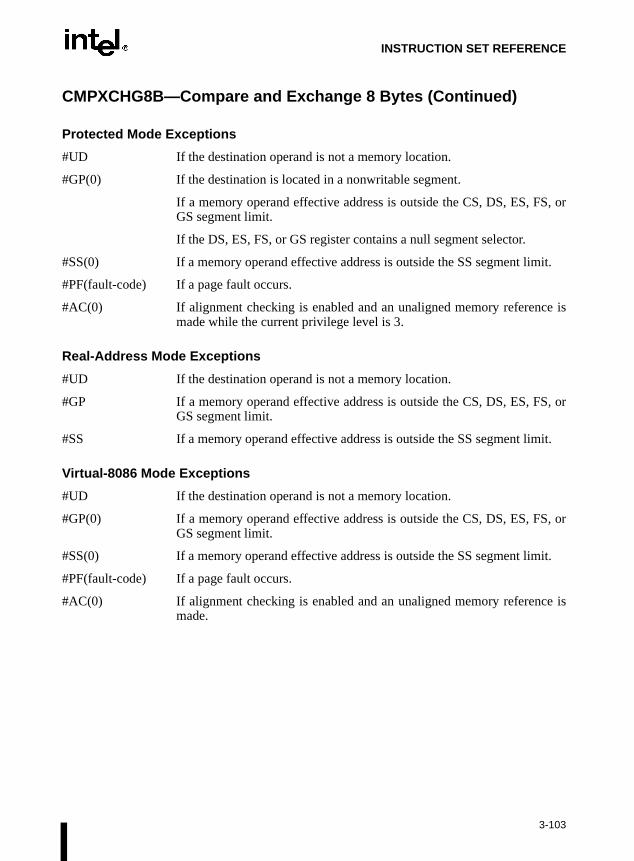
INSTRUCTION SET REFERENCE
CMPXCHG8B—Compare and Exchange 8 Bytes (Continued)
Protected Mode Exceptions
#UD If the destination operand is not a memory location.
#GP(0) If the destination is located in a nonwritable segment.
If a memory operand effective address is outside the CS, DS, ES, FS, orGS segment limit.
If the DS, ES, FS, or GS register contains a null segment selector.
#SS(0) If a memory operand effective address is outside the SS segment limit.
#PF(fault-code) If a page fault occurs.
#AC(0) If alignment checking is enabled and an unaligned memory reference ismade while the current privilege level is 3.
Real-Address Mode Exceptions
#UD If the destination operand is not a memory location.
#GP If a memory operand effective address is outside the CS, DS, ES, FS, orGS segment limit.
#SS If a memory operand effective address is outside the SS segment limit.
Virtual-8086 Mode Exceptions
#UD If the destination operand is not a memory location.
#GP(0) If a memory operand effective address is outside the CS, DS, ES, FS, orGS segment limit.
#SS(0) If a memory operand effective address is outside the SS segment limit.
#PF(fault-code) If a page fault occurs.
#AC(0) If alignment checking is enabled and an unaligned memory reference ismade.
3-103

INSTRUCTION SET REFERENCE
COMISS—Scalar Ordered Single-FP Compare and Set EFLAGS
Description
The COMISS instruction compares two SP FP numbers and sets the ZF,PF,CF bits in theEFLAGS register as described above. Although the data type is packed single-FP, only the lowerSP numbers are compared. In addition, the OF, SF, and AF bits in the EFLAGS register arezeroed out. The unordered predicate is returned if either input is a NaN (qNaN or sNaN).
Figure 3-23. Operation of the COMISS Instruction, Condition One
EFLAGS: OF,SF,AF=000EFLAGS: ZF,PF,CF=111
MXCSR flags: Invalid flag is set
Opcode Instruction Description
0F,2F,/r COMISS xmm1, xmm2/m32
Compare lower SP FP number in XMM1 register with lower SP FP number in XMM2/Mem and set the status flags accordingly
= = ==
Xmm1
Xmm2/m32
Xmm1
COMISS xmm1, xmm2/m32
3-104

INSTRUCTION SET REFERENCE
COMISS—Scalar Ordered Single-FP Compare And Set EFLAGS (Continued)
Figure 3-24. Operation of the COMISS Instruction, Condition Two
EFLAGS: OF,SF,AF=000EFLAGS: ZF,PF,CF=000
MXCSR flags: Invalid flag is set
Figure 3-25. Operation of the COMISS Instruction, Condition Three
EFLAGS: OF,SF,AF=000EFLAGS: ZF,PF,CF=001
MXCSR flags: Invalid flag is set
Xmm1
Xmm2/m32
COMISS xmm1, xmm2/m32
6.0
9.0
9.0
= = = =
Xmm1
= = ==
Xmm1
Xmm2/m32
Xmm1
COMISS xmm1, xmm2/m32
3-105

INSTRUCTION SET REFERENCE
COMISS—Scalar Ordered Single-FP Compare And Set EFLAGS (Continued)
Figure 3-26. Operation of the COMISS Instruction, Condition Four
EFLAGS: OF,SF,AF=000EFLAGS: ZF,PF,CF=100
MXCSR flags: Invalid flag is set
Xmm1
Xmm2/m32
COMISS xmm1, xmm2/m32
6.0
6.0
6.0
= = = =
Xmm1
3-106
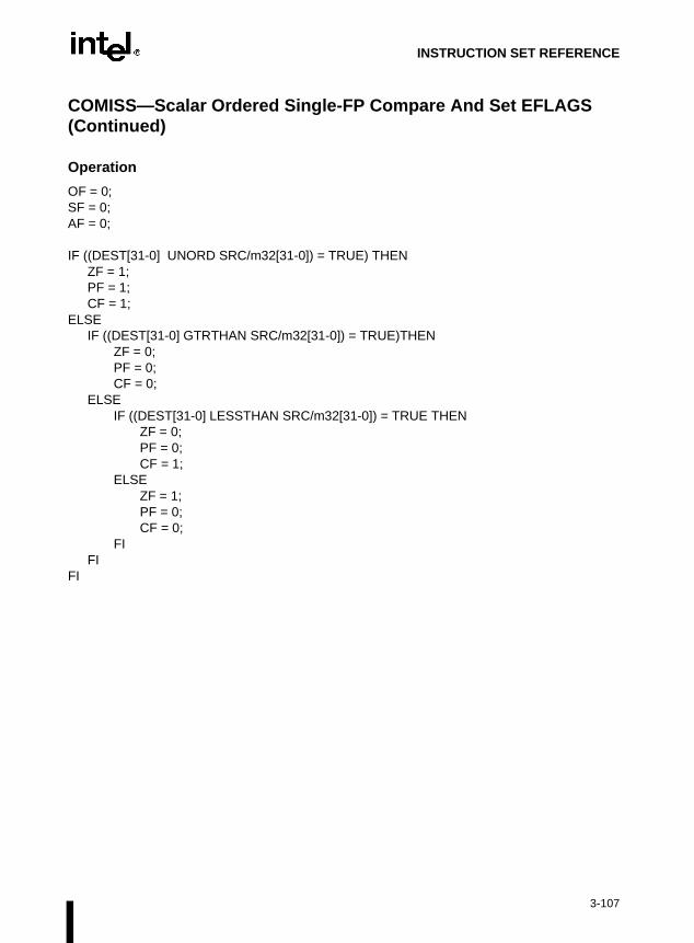
INSTRUCTION SET REFERENCE
COMISS—Scalar Ordered Single-FP Compare And Set EFLAGS (Continued)
Operation
OF = 0;SF = 0;AF = 0;
IF ((DEST[31-0] UNORD SRC/m32[31-0]) = TRUE) THENZF = 1;PF = 1;CF = 1;
ELSEIF ((DEST[31-0] GTRTHAN SRC/m32[31-0]) = TRUE)THEN
ZF = 0;PF = 0;CF = 0;
ELSEIF ((DEST[31-0] LESSTHAN SRC/m32[31-0]) = TRUE THEN
ZF = 0;PF = 0;CF = 1;
ELSEZF = 1;PF = 0;CF = 0;
FIFI
FI
3-107

INSTRUCTION SET REFERENCE
COMISS—Scalar Ordered Single-FP Compare And Set EFLAGS (Continued)
Intel C/C++ Compiler Intrinsic Equivalents
int_mm_comieq_ss(__m128 a, __m128 b)
Compares the lower SP FP value of a and b for a equal to b. If a and b are equal, 1 is returned.Otherwise 0 is returned.
int_mm_comilt_ss(__m128 a, __m128 b)
Compares the lower SP FP value of a and b for a less than b. If a is less than b, 1 is returned.Otherwise 0 is returned.
int_mm_comile_ss(__m128 a, __m128 b)
Compares the lower SP FP value of a and b for a less than or equal to b. If a is less than or equalto b, 1 is returned. Otherwise 0 is returned.
int_mm_comigt_ss(__m128 a, __m128 b)
Compares the lower SP FP value of a and b for a greater than b. If a is greater than b are equal,1 is returned. Otherwise 0 is returned.
int_mm_comige_ss(__m128 a, __m128 b)
Compares the lower SP FP value of a and b for a greater than or equal to b. If a is greater thanor equal to b, 1 is returned. Otherwise 0 is returned.
int_mm_comineq_ss(__m128 a, __m128 b)
Compares the lower SP FP value of a and b for a not equal to b. If a and b are not equal, 1 isreturned. Otherwise 0 is returned.
Exceptions
None.
3-108

INSTRUCTION SET REFERENCE
COMISS—Scalar Ordered Single-FP Compare And Set EFLAGS (Continued)
Numeric Exceptions
Invalid (if sNaN or qNaN operands), Denormal. Integer EFLAGS values will not be updated inthe presence of unmasked numeric exceptions.
#GP(0) For an illegal memory operand effective address in the CS, DS, ES, FS, orGS segments.
#SS(0) For an illegal address in the SS segment.
#PF (fault-code) For a page fault.
#UD If CR0.EM = 1.
#NM If TS bit in CR0 is set.
#AC For unaligned memory reference. To enable #AC exceptions, three condi-tions must be true(CR0.AM is set; EFLAGS.AC is set; current CPL is 3).
#XM For an unmasked Streaming SIMD Extension numeric exception(CR4.OSXMMEXCPT =1).
#UD For an unmasked Streaming SIMD Extension numeric exception(CR4.OSXMMEXCPT =0).
#UD If CR4.OSFXSR(bit 9) = 0.
#UD If CPUID.XMM(EDX bit 25) = 0.
Real Address Mode Exceptions
Interrupt 13 If any part of the operand would lie outside of the effective address spacefrom 0 to 0FFFFH.
#UD If CR0.EM = 1.
#NM If TS bit in CR0 is set.
#XM For an unmasked Streaming SIMD Extension numeric exception(CR4.OSXMMEXCPT =1).
#UD For an unmasked Streaming SIMD Extension numeric exception(CR4.OSXMMEXCPT =0).
#UD If CR4.OSFXSR(bit 9) = 0.
#UD If CPUID.XMM(EDX bit 25) = 0.
3-109

INSTRUCTION SET REFERENCE
COMISS—Scalar Ordered Single-FP Compare And Set EFLAGS (Continued)
Virtual 8086 Mode Exceptions
Same exceptions as in Real Address Mode.
#AC For unaligned memory reference if the current privilege level is 3.
#PF (fault-code) For a page fault.
Comments
COMISS differs from UCOMISS and COMISS in that it signals an invalid numeric exceptionwhen a source operand is either a qNaN or an sNaN operand; UCOMISS signals invalid only asource operand is an sNaN.
The usage of Repeat (F2H, F3H) and Operand-Size (66H) prefixes with COMISS is reserved.Different processor implementations may handle this prefix differently. Usage of this prefixwith COMISS risks incompatibility with future processors.
3-110

INSTRUCTION SET REFERENCE
l,
CPUID—CPU Identification
Description
This instruction provides processor identification information in registers EAX, EBX, ECX, andEDX. This information identifies Intel as the vendor, gives the family, model, and stepping ofprocessor, feature information, and cache information. An input value loaded into the EAXregister determines what information is returned, as shown in Table 3-6.
The CPUID instruction can be executed at any privilege level to serialize instruction execution.Serializing instruction execution guarantees that any modifications to flags, registers, andmemory for previous instructions are completed before the next instruction is fetched andexecuted. For more information, refer to Section 7.4., Serializing Instructions in Chapter 7,Multiple-Processor Management of the Intel Architecture Software Developer’s ManuaVolume 3.
When the input value in register EAX is 0, the processor returns the highest value the CPUIDinstruction recognizes in the EAX register (refer to Table 3-6). A vendor identification string isreturned in the EBX, EDX, and ECX registers. For Intel processors, the vendor identificationstring is “GenuineIntel” as follows:
EBX ← 756e6547h (* "Genu", with G in the low nibble of BL *)EDX ← 49656e69h (* "ineI", with i in the low nibble of DL *)ECX ← 6c65746eh (* "ntel", with n in the low nibble of CL *)
Opcode Instruction Description
0F A2 CPUID EAX ← Processor identification information
Table 3-6. Information Returned by CPUID Instruction
Initial EAX Value Information Provided about the Processor
0 EAX
EBXECXEDX
Maximum CPUID Input Value (2 for the Pentium® Pro processor and 1 for the Pentium® processor and the later versions of Intel486™ processor that support the CPUID instruction).“Genu”“ntel”“ineI”
1 EAXEBXECXEDX
Version Information (Type, Family, Model, and Stepping ID)ReservedReservedFeature Information
2 EAXEBXECXEDX
Cache and TLB InformationCache and TLB InformationCache and TLB InformationCache and TLB Information
3-111

INSTRUCTION SET REFERENCE
CPUID—CPU Identification (Continued)
When the input value is 1, the processor returns version information in the EAX register andfeature information in the EDX register (refer to Figure 3-27).
The version information consists of an Intel Architecture family identifier, a model identifier, astepping ID, and a processor type. The model, family, and processor type for the first processorin the Intel Pentium® Pro family is as follows:
• Model—0001B
• Family—0110B
• Processor Type—00B
Figure 3-27. Version and Feature Information in Registers EAX and EDX
31 12 11 8 7 4 3 0
EAX
Family (0110B for the Pentium® Pro Processor Family)Model (Beginning with 0001B)
1314
Processor Type
ModelFamilyStepping
ID
Streaming SIMD Extensions
3-112

INSTRUCTION SET REFERENCE
CPUID—CPU Identification (Continued)
Refer to AP-485, Intel Processor Identification and the CPUID Instruction (Order Number241618), the Intel Pentium® Pro Processor Specification Update (Order Number 242689), andthe Intel Pentium® Processor Specification Update (Order Number 242480) for more informa-tion on identifying earlier Intel Architecture processors.
The available processor types are given in Table 3-7. Intel releases information on stepping IDsas needed.
* Not applicable to Intel386™ and Intel486™ processors.
Table 3-7. Processor Type Field
Type Encoding
Original OEM Processor 00B
Intel OverDrive® Processor 01B
Dual processor * 10B
Intel reserved. 11B
3-113
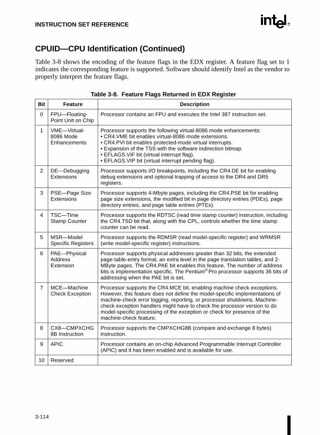
INSTRUCTION SET REFERENCE
CPUID—CPU Identification (Continued)
Table 3-8 shows the encoding of the feature flags in the EDX register. A feature flag set to 1indicates the corresponding feature is supported. Software should identify Intel as the vendor toproperly interpret the feature flags.
Table 3-8. Feature Flags Returned in EDX Register
Bit Feature Description
0 FPU—Floating-Point Unit on Chip
Processor contains an FPU and executes the Intel 387 instruction set.
1 VME—Virtual-8086 Mode Enhancements
Processor supports the following virtual-8086 mode enhancements:• CR4.VME bit enables virtual-8086 mode extensions.• CR4.PVI bit enables protected-mode virtual interrupts.• Expansion of the TSS with the software indirection bitmap.• EFLAGS.VIF bit (virtual interrupt flag).• EFLAGS.VIP bit (virtual interrupt pending flag).
2 DE—Debugging Extensions
Processor supports I/O breakpoints, including the CR4.DE bit for enabling debug extensions and optional trapping of access to the DR4 and DR5 registers.
3 PSE—Page Size Extensions
Processor supports 4-Mbyte pages, including the CR4.PSE bit for enabling page size extensions, the modified bit in page directory entries (PDEs), page directory entries, and page table entries (PTEs).
4 TSC—Time Stamp Counter
Processor supports the RDTSC (read time stamp counter) instruction, including the CR4.TSD bit that, along with the CPL, controls whether the time stamp counter can be read.
5 MSR—Model Specific Registers
Processor supports the RDMSR (read model-specific register) and WRMSR (write model-specific register) instructions.
6 PAE—Physical Address Extension
Processor supports physical addresses greater than 32 bits, the extended page-table-entry format, an extra level in the page translation tables, and 2-MByte pages. The CR4.PAE bit enables this feature. The number of address bits is implementation specific. The Pentium® Pro processor supports 36 bits of addressing when the PAE bit is set.
7 MCE—Machine Check Exception
Processor supports the CR4.MCE bit, enabling machine check exceptions. However, this feature does not define the model-specific implementations of machine-check error logging, reporting, or processor shutdowns. Machine-check exception handlers might have to check the processor version to do model-specific processing of the exception or check for presence of the machine-check feature.
8 CX8—CMPXCHG8B Instruction
Processor supports the CMPXCHG8B (compare and exchange 8 bytes) instruction.
9 APIC Processor contains an on-chip Advanced Programmable Interrupt Controller (APIC) and it has been enabled and is available for use.
10 Reserved
3-114

INSTRUCTION SET REFERENCE
CPUID—CPU Identification (Continued)
Bit Feature Description
11 SEP—Fast System Call Indicates whether the processor supports the Fast System Call instructions, SYSENTER and SYSEXIT.
12 MTRR—Memory Type Range Registers
Processor supports machine-specific memory-type range registers (MTRRs). The MTRRs contains bit fields that indicate the processor’s MTRR capabilities, including which memory types the processor supports, the number of variable MTRRs the processor supports, and whether the processor supports fixed MTRRs.
13 PGE—PTE Global Flag Processor supports the CR4.PGE flag enabling the global bit in both PTDEs and PTEs. These bits are used to indicate translation lookaside buffer (TLB) entries that are common to different tasks and need not be flushed when control register CR3 is written.
14 MCA—Machine Check Architecture
Processor supports the MCG_CAP (machine check global capability) MSR. The MCG_CAP register indicates how many banks of error reporting MSRs the processor supports.
15 CMOV—Conditional Move and Compare Instructions
Processor supports the CMOVcc instruction and, if the FPU feature flag (bit 0) is also set, supports the FCMOVcc and FCOMI instructions.
16 FGPAT—Page Attribute Table
Processor supports CMOVcc, and if the FPU feature flag (bit 0) is also set, supports the FMOVCC and FCOMI instructions.
17 PSE-36—36-bit Page Size Extension
Processor supports 4MB pages with 36 bit physical addresses.
18 PN—Processor Number
Processor supports the 96-bit Processor Number feature, and the feature is enabled
19-22 Reserved
23 MMX™ Technology Processor supports the MMX™ instruction set. These instructions operate in parallel on multiple data elements (8 bytes, 4 words, or 2 doublewords) packed into quadword registers or memory locations.
24 FXSR—Fast FP/MMX™ Technology/Streaming SIMD Extensions save/restore
Indicates whether the processor supports the FXSAVE and FXRSTOR instructions for fast save and restore of the floating point context. Presence of this bit also indicates that CR4.OSFXSR is available for an operating system to indicate that it uses the fast save/restore instructions.
25 XMM—Streaming SIMD Extensions
Processor supports the Streaming SIMD Extensions instruction set.
26-31 Reserved
3-115

INSTRUCTION SET REFERENCE
ternalisters
CPUID—CPU Identification (Continued)
When the input value is 2, the processor returns information about the processor’s incaches and TLBs in the EAX, EBX, ECX, and EDX registers. The encoding of these regis as follows:
• The least-significant byte in register EAX (register AL) indicates the number of times theCPUID instruction must be executed with an input value of 2 to get a complete descriptionof the processor’s caches and TLBs. The Pentium® Pro family of processors will return a 1.
• The most significant bit (bit 31) of each register indicates whether the register containsvalid information (cleared to 0) or is reserved (set to 1).
• If a register contains valid information, the information is contained in one-bytedescriptors. Table 3-9 shows the encoding of these descriptors.
Table 3-9. Encoding of Cache and TLB Descriptors
Descriptor Value Cache or TLB Description
00H Null descriptor
01H Instruction TLB: 4K-Byte Pages, 4-way set associative, 32 entries
02H Instruction TLB: 4M-Byte Pages, fully associative, two entries
03H Data TLB: 4K-Byte Pages, 4-way set associative, 64 entries
04H Data TLB: 4M-Byte Pages, 4-way set associative, eight entries
06H Instruction cache: 8K Bytes, 4-way set associative, 32 byte line size
08H Instruction cache: 16K Bytes, 4-way set associative, 32 byte line size
0AH Data cache: 8K Bytes, 2-way set associative, 32 byte line size
0CH Data cache: 16K Bytes, 2-way or 4-way set associative, 32 byte line size
40H No L2 Cache
41H L2 Unified cache: 128K Bytes, 4-way set associative, 32 byte line size
42H L2 Unified cache: 256K Bytes, 4-way set associative, 32 byte line size
43H L2 Unified cache: 512K Bytes, 4-way set associative, 32 byte line size
44H L2 Unified cache: 1M Byte, 4-way set associative, 32 byte line size
45H L2 Unified cache: 2M Byte, 4-way set associative, 32 byte line size
3-116

INSTRUCTION SET REFERENCE
te
h a
ith a
tive,
anyAGS set or
CPUID—CPU Identification (Continued)
The first member of the Pentium® Pro processor family will return the following informationabout caches and TLBs when the CPUID instruction is executed with an input value of 2:
EAX 03 02 01 01H
EBX 0H
ECX 0H
EDX 06 04 0A 42H
These values are interpreted as follows:
• The least-significant byte (byte 0) of register EAX is set to 01H, indicating that the CPUIDinstruction needs to be executed only once with an input value of 2 to retrieve completeinformation about the processor’s caches and TLBs.
• The most-significant bit of all four registers (EAX, EBX, ECX, and EDX) is set to 0,indicating that each register contains valid 1-byte descriptors.
• Bytes 1, 2, and 3 of register EAX indicate that the processor contains the following:
— 01H—A 32-entry instruction TLB (4-way set associative) for mapping 4-KBypages.
— 02H—A 2-entry instruction TLB (fully associative) for mapping 4-MByte pages.
— 03H—A 64-entry data TLB (4-way set associative) for mapping 4-KByte pages.
• The descriptors in registers EBX and ECX are valid, but contain null descriptors.
• Bytes 0, 1, 2, and 3 of register EDX indicate that the processor contains the following:
— 42H—A 256-KByte unified cache (the L2 cache), 4-way set associative, wit32-byte cache line size.
— 0AH—An 8-KByte data cache (the L1 data cache), 2-way set associative, w32-byte cache line size.
— 04H—An 8-entry data TLB (4-way set associative) for mapping 4M-byte pages.
— 06H—An 8-KByte instruction cache (the L1 instruction cache), 4-way set associawith a 32-byte cache line size.
Intel Architecture Compatibility
The CPUID instruction is not supported in early models of the Intel486™ processor or inIntel Architecture processor earlier than the Intel486™ processor. The ID flag in the EFLregister can be used to determine if this instruction is supported. If a procedure is able toclear this flag, the CPUID is supported by the processor running the procedure.
3-117

INSTRUCTION SET REFERENCE
CPUID—CPU Identification (Continued)
Operation
CASE (EAX) OFEAX = 0:
EAX ← highest input value understood by CPUID; (* 2 for Pentium® Pro processor *)EBX ← Vendor identification string;EDX ← Vendor identification string;ECX ← Vendor identification string;
BREAK;EAX = 1:
EAX[3:0] ← Stepping ID; EAX[7:4] ← Model; EAX[11:8] ← Family; EAX[13:12] ← Processor type; EAX[31:12] ← Reserved;EBX ← Reserved;ECX ← Reserved;EDX ← Feature flags; (* Refer to Figure 3-27 *)
BREAK;EAX = 2:
EAX ← Cache and TLB information; EBX ← Cache and TLB information; ECX ← Cache and TLB information;
EDX ← Cache and TLB information; BREAK;DEFAULT: (* EAX > highest value recognized by CPUID *)
EAX ← reserved, undefined; EBX ← reserved, undefined; ECX ← reserved, undefined; EDX ← reserved, undefined;
BREAK;ESAC;
Flags Affected
None.
Exceptions (All Operating Modes)
None.
3-118

INSTRUCTION SET REFERENCE
CVTPI2PS—Packed Signed INT32 to Packed Single-FP Conversion
Description
The CVTPI2PS instruction converts signed 32-bit integers to SP FP numbers. When the conver-sion is inexact, rounding is done according to MXCSR. A #MF fault is signalled if there is apending x87 fault.
Figure 3-28. Operation of the CVTPI2PS Instruction
Operation
DEST[31-0] = (float) (SRC/m64[31-0]);DEST[63-32] = (float) (SRC/m64[63-32]);DEST[95-64] = DEST[95-64];DEST[127-96] = DEST[127-96];
Intel C/C++ Compiler Intrinsic Equivalent
__m128 _mm_cvt_pi2ps(__m128 a, __m64 b)
__m128 _mm_cvtpi32_ps(__m128 a, __m64 b)
Convert the two 32-bit integer values in packed form in b to two SP FP values; the upper twoSP FP values are passed through from a.
Opcode Instruction Description
0F,2A,/r CVTPI2PS xmm, mm/m64 Convert two 32-bit signed integers from MM/Mem to two SP FP.
Xmm1
Float Float
Mm1/m64
CVTPI2PS xmm1, xmm1/m64
1.0
Xmm1
3-119

INSTRUCTION SET REFERENCE
CVTPI2PS—Packed Signed INT32 to Packed Single-FP Conversion (Continued)
Exceptions
None.
Numeric Exceptions
Precision.
Protected Mode Exceptions
#GP(0) For an illegal memory operand effective address in the CS, DS, ES, FS, orGS segments.
#SS(0) For an illegal address in the SS segment.
#PF (fault-code) For a page fault.
#UD If CR0.EM = 1.
#NM If TS bit in CR0 is set.
#MF If there is a pending FPU exception.
#AC For unaligned memory reference. To enable #AC exceptions, three condi-tions must be true(CR0.AM is set; EFLAGS.AC is set; current CPL is 3).
#XM For an unmasked Streaming SIMD Extension numeric exception(CR4.OSXMMEXCPT =1).
#UD For an unmasked Streaming SIMD Extension numeric exception(CR4.OSXMMEXCPT =0).
#UD If CR4.OSFXSR(bit 9) = 0.
#UD If CPUID.XMM(EDX bit 25) = 0.
3-120

INSTRUCTION SET REFERENCE
CVTPI2PS—Packed Signed INT32 to Packed Single-FP Conversion (Continued)
Real Address Mode Exceptions
Interrupt 13 If any part of the operand would lie outside of the effective address spacefrom 0 to 0FFFFH.
#UD If CR0.EM = 1.
#NM If TS bit in CR0 is set.
#MF If there is a pending FPU exception.
#AC For unaligned memory reference.
#XM For an unmasked Streaming SIMD Extension numeric exception(CR4.OSXMMEXCPT =1).
#UD For an unmasked Streaming SIMD Extension numeric exception(CR4.OSXMMEXCPT =0).
#UD If CR4.OSFXSR(bit 9) = 0.
#UD If CPUID.XMM(EDX bit 25) = 0.
Virtual 8086 Mode Exceptions
Same exceptions as in Real Address Mode.
#AC For unaligned memory reference if the current privilege level is 3.
#PF (fault-code) For a page fault.
3-121
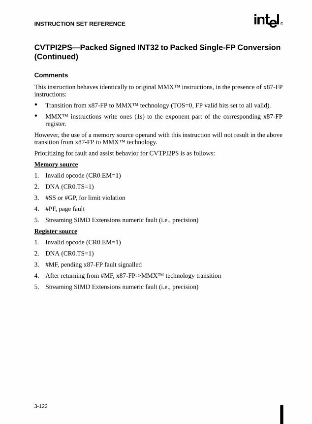
INSTRUCTION SET REFERENCE
-FP
-FP
bove
CVTPI2PS—Packed Signed INT32 to Packed Single-FP Conversion (Continued)
Comments
This instruction behaves identically to original MMX™ instructions, in the presence of x87instructions:
• Transition from x87-FP to MMX™ technology (TOS=0, FP valid bits set to all valid).
• MMX™ instructions write ones (1s) to the exponent part of the corresponding x87register.
However, the use of a memory source operand with this instruction will not result in the atransition from x87-FP to MMX™ technology.
Prioritizing for fault and assist behavior for CVTPI2PS is as follows:
Memory source
1. Invalid opcode (CR0.EM=1)
2. DNA (CR0.TS=1)
3. #SS or #GP, for limit violation
4. #PF, page fault
5. Streaming SIMD Extensions numeric fault (i.e., precision)
Register source
1. Invalid opcode (CR0.EM=1)
2. DNA (CR0.TS=1)
3. #MF, pending x87-FP fault signalled
4. After returning from #MF, x87-FP->MMX™ technology transition
5. Streaming SIMD Extensions numeric fault (i.e., precision)
3-122
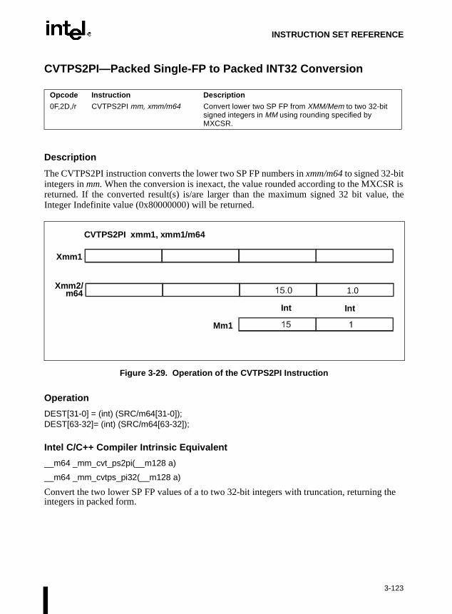
INSTRUCTION SET REFERENCE
CVTPS2PI—Packed Single-FP to Packed INT32 Conversion
Description
The CVTPS2PI instruction converts the lower two SP FP numbers in xmm/m64 to signed 32-bitintegers in mm. When the conversion is inexact, the value rounded according to the MXCSR isreturned. If the converted result(s) is/are larger than the maximum signed 32 bit value, theInteger Indefinite value (0x80000000) will be returned.
Figure 3-29. Operation of the CVTPS2PI Instruction
Operation
DEST[31-0] = (int) (SRC/m64[31-0]);DEST[63-32]= (int) (SRC/m64[63-32]);
Intel C/C++ Compiler Intrinsic Equivalent
__m64 _mm_cvt_ps2pi(__m128 a)
__m64 _mm_cvtps_pi32(__m128 a)
Convert the two lower SP FP values of a to two 32-bit integers with truncation, returning the integers in packed form.
Opcode Instruction Description
0F,2D,/r CVTPS2PI mm, xmm/m64 Convert lower two SP FP from XMM/Mem to two 32-bit signed integers in MM using rounding specified by MXCSR.
Xmm1
Xmm2/m64
CVTPS2PI xmm1, xmm1/m64
1.0
Mm1
Int Int
3-123
INSTRUCTION SET REFERENCE
CVTPS2PI—Packed Single-FP to Packed INT32 Conversion (Continued)
Exceptions
None.
Numeric Exceptions
Invalid, Precision.
Protected Mode Exceptions
#GP(0) For an illegal memory operand effective address in the CS, DS, ES, FS, orGS segments.
#SS(0) For an illegal address in the SS segment.
#PF (fault-code) For a page fault.
#UD If CR0.EM = 1.
#NM If TS bit in CR0 is set.
#MF If there is a pending FPU exception.
#AC For unaligned memory reference. To enable #AC exceptions, three condi-tions must be true(CR0.AM is set; EFLAGS.AC is set; current CPL is 3).
#XM For an unmasked Streaming SIMD Extension numeric exception(CR4.OSXMMEXCPT =1).
#UD For an unmasked Streaming SIMD Extension numeric exception(CR4.OSXMMEXCPT =0).
#UD If CR4.OSFXSR(bit 9) = 0.
#UD If CPUID.XMM(EDX bit 25) = 0.
3-124

INSTRUCTION SET REFERENCE
CVTPS2PI—Packed Single-FP to Packed INT32 Conversion (Continued)
Real Address Mode Exceptions
Interrupt 13 If any part of the operand would lie outside of the effective address spacefrom 0 to 0FFFFH.
#UD If CR0.EM = 1.
#NM If TS bit in CR0 is set.
#MF If there is a pending FPU exception.
#XM For an unmasked Streaming SIMD Extension numeric exception(CR4.OSXMMEXCPT =1).
#UD For an unmasked Streaming SIMD Extension numeric exception(CR4.OSXMMEXCPT =0).
#UD If CR4.OSFXSR(bit 9) = 0.
#UD If CPUID.XMM(EDX bit 25) = 0.
Virtual 8086 Mode Exceptions
Same exceptions as in Real Address Mode.
#AC For unaligned memory reference if the current privilege level is 3.
#PF (fault-code) For a page fault.
3-125

INSTRUCTION SET REFERENCE
-FP
-FP
CVTPS2PI—Packed Single-FP to Packed INT32 Conversion (Continued)
Comments
This instruction behaves identically to original MMX™ instructions, in the presence of x87instructions:
• Transition from x87-FP to MMX™ technology (TOS=0, FP valid bits set to all valid).
• MMX™ instructions write ones (1s) to the exponent part of the corresponding x87register.
Prioritizing for fault and assist behavior for CVTPS2PI is as follows:
Memory source
1. Invalid opcode (CR0.EM=1)
2. DNA (CR0.TS=1)
3. #MF, pending x87-FP fault signalled
4. After returning from #MF, x87-FP->MMX™ technology transition
5. #SS or #GP, for limit violation
6. #PF, page fault
7. Streaming SIMD Extensions numeric fault (i.e., invalid, precision)
Register source
1. Invalid opcode (CR0.EM=1)
2. DNA (CR0.TS=1)
3. #MF, pending x87-FP fault signalled
4. After returning from #MF, x87-FP->MMX™ technology transition
5. Streaming SIMD Extensions numeric fault (i.e., precision)
3-126

INSTRUCTION SET REFERENCE
CVTSI2SS—Scalar Signed INT32 to Single-FP Conversion
Description
The CVTSI2SS instruction converts a signed 32-bit integer from memory or from a 32-bitinteger register to an SP FP number. When the conversion is inexact, rounding is done accordingto the MXCSR.
Figure 3-30. Operation of the CVTSI2SS Instruction
Operation
DEST[31-0] = (float) (R/m32);DEST[63-32] = DEST[63-32];DEST[95-64] = DEST[95-64];DEST[127-96] = DEST[127-96];
Intel C/C++ Compiler Intrinsic Equivalent
__m128 _mm_cvt_si2ss(__m128 a, int b)
__m128 _mm_cvtsi32_ss(__m128 a, int b)
Convert the 32-bit integer value b to an SP FP value; the upper three SP FP values are passedthrough from a.
Opcode Instruction Description
F3,0F,2A,/r CVTSI2SS xmm, r/m32 Convert one 32-bit signed integer from Integer Reg/Mem to one SP FP.
CVTSI2SS xmm1, r/m32
Xmm1
R/m32
Xmm1
Float
3-127

INSTRUCTION SET REFERENCE
CVTSI2SS—Scalar Signed INT32 to Single-FP Conversion (Continued)
Exceptions
None.
Numeric Exceptions
Precision.
Protected Mode Exceptions
#GP(0) For an illegal memory operand effective address in the CS, DS, ES, FS, orGS segments.
#SS(0) For an illegal address in the SS segment.
#PF (fault-code) For a page fault.
#UD If CR0.EM = 1.
#NM If TS bit in CR0 is set.
#AC For unaligned memory reference. To enable #AC exceptions, three condi-tions must be true(CR0.AM is set; EFLAGS.AC is set; current CPL is 3).
#XM For an unmasked Streaming SIMD Extension numeric exception(CR4.OSXMMEXCPT =1).
#UD For an unmasked Streaming SIMD Extension numeric exception(CR4.OSXMMEXCPT =0).
#UD If CR4.OSFXSR(bit 9) = 0.
#UD If CPUID.XMM(EDX bit 25) = 0.
3-128

INSTRUCTION SET REFERENCE
CVTSI2SS—Scalar Signed INT32 to Single-FP Conversion (Continued)
Real Address Mode Exceptions
Interrupt 13 If any part of the operand would lie outside of the effective address spacefrom 0 to 0FFFFH.
#UD If CR0.EM = 1.
#NM If TS bit in CR0 is set.
#XM For an unmasked Streaming SIMD Extension numeric exception(CR4.OSXMMEXCPT =1).
#UD For an unmasked Streaming SIMD Extension numeric exception(CR4.OSXMMEXCPT =0).
#UD If CR4.OSFXSR(bit 9) = 0.
#UD If CPUID.XMM(EDX bit 25) = 0.
Virtual 8086 Mode Exceptions
Same exceptions as in Real Address Mode.
#AC For unaligned memory reference if the current privilege level is 3.
#PF (fault-code) For a page fault.
3-129

INSTRUCTION SET REFERENCE
CVTSS2SI—Scalar Single-FP to Signed INT32 Conversion
Description
The CVTSS2SI instruction converts an SP FP number to a signed 32-bit integer and returns itin the 32-bit integer register. When the conversion is inexact, the rounded value according to theMXCSR is returned. If the converted result is larger than the maximum signed 32 bit integer, theInteger Indefinite value (0x80000000) will be returned.
Figure 3-31. Operation of the CVTSS2SI Instruction
Operation
r32 = (int) (SRC/m32[31-0]);
Intel C/C++ Compiler Intrinsic Equivalent
int_mm_cvt_ss2si(__m128 a)
int_mm_cvtss_si32(__m128 a)
Convert the lower SP FP value of a to a 32-bit integer according to the current rounding mode.
Opcode Instruction Description
F3,0F,2D,/r CVTSS2SI r32, xmm/m32 Convert one SP FP from XMM/Mem to one 32 bit signed integer using rounding mode specified by MXCSR, and move the result to an integer register.
Xmm1/m32
CVTSS2SI r32, xmm1/m32
r32
r32
3-130

INSTRUCTION SET REFERENCE
CVTSS2SI—Scalar Single-FP to Signed INT32 Conversion (Continued)
Exceptions
None.
Numeric Exceptions
Invalid, Precision.
Protected Mode Exceptions
#GP(0) For an illegal memory operand effective address in the CS, DS, ES, FS, orGS segments.
#SS(0) For an illegal address in the SS segment.
#PF (fault-code) For a page fault.
#UD If CR0.EM = 1.
#NM If TS bit in CR0 is set.
#AC For unaligned memory reference.To enable #AC exceptions, three condi-tions must be true(CR0.AM is set; EFLAGS.AC is set; current CPL is 3).
#XM For an unmasked Streaming SIMD Extension numeric exception(CR4.OSXMMEXCPT =1).
#UD For an unmasked Streaming SIMD Extension numeric exception(CR4.OSXMMEXCPT = 0).
#UD If CR4.OSFXSR(bit 9) = 0.
#UD If CPUID.XMM(EDX bit 25) = 0.
3-131

INSTRUCTION SET REFERENCE
CVTSS2SI—Scalar Single-FP to Signed INT32 Conversion (Continued)
Real Address Mode Exceptions
Interrupt 13 If any part of the operand would lie outside of the effective address spacefrom 0 to 0FFFFH.
#UD If CR0.EM = 1.
#NM If TS bit in CR0 is set.
#XM For an unmasked Streaming SIMD Extension numeric exception(CR4.OSXMMEXCPT =1).
#UD For an unmasked Streaming SIMD Extension numeric exception(CR4.OSXMMEXCPT =0).
#UD If CR4.OSFXSR(bit 9) = 0.
#UD If CPUID.XMM(EDX bit 25) = 0.
Virtual 8086 Mode Exceptions
Same exceptions as in Real Address Mode.
#AC For unaligned memory reference if the current privilege level is 3.
#PF (fault-code) For a page fault.
3-132

INSTRUCTION SET REFERENCE
CVTTPS2PI—Packed Single-FP to Packed INT32 Conversion (Truncate)
Description
The CVTTPS2PI instruction converts the lower two SP FP numbers in xmm/m64 to two 32-bitsigned integers in mm. If the conversion is inexact, the truncated result is returned. If theconverted result(s) is/are larger than the maximum signed 32 bit value, the Integer Indefinitevalue (0x80000000) will be returned.
Figure 3-32. Operation of the CVTTPS2PI Instruction
Operation
DEST[31-0] = (int) (SRC/m64[31-0]);DEST[63-32]= (int) (SRC/m64[63-32]);
Opcode Instruction Description
0F,2C,/r CVTTPS2PI mm, xmm/m64 Convert lower two SP FP from XMM/Mem to two 32-bit signed integers in MM using truncate.
Mm1
Xmm1/m64
CVTTPS2PI mm1, xmm1/m64
1.0
Mm1
Int Int
3-133

INSTRUCTION SET REFERENCE
CVTTPS2PI—Packed Single-FP to Packed INT32 Conversion (Truncate) (Continued)
Intel C/C++ Compiler Intrinsic Equivalent
__m64 _mm_cvtt_ps2pi(__m128 a)
__m64 _mm_cvttps_pi32(__m128 a)
Convert the two lower SP FP values of a to two 32-bit integers according to the current roundingmode, returning the integers in packed form.
Exceptions
None.
Numeric Exceptions
Invalid, Precision.
Protected Mode Exceptions
#GP(0) For an illegal memory operand effective address in the CS, DS, ES, FS, orGS segments.
#SS(0) For an illegal address in the SS segment.
#PF (fault-code) For a page fault.
#UD If CR0.EM = 1.
#NM If TS bit in CR0 is set.
#MF If there is a pending FPU exception.
#AC For unaligned memory reference. To enable #AC exceptions, three condi-tions must be true(CR0.AM is set; EFLAGS.AC is set; current CPL is 3).
#XM For an unmasked Streaming SIMD Extension numeric exception(CR4.OSXMMEXCPT =1).
#UD For an unmasked Streaming SIMD Extension numeric exception(CR4.OSXMMEXCPT =0).
#UD If CR4.OSFXSR(bit 9) = 0.
#UD If CPUID.XMM(EDX bit 25) = 0.
3-134

INSTRUCTION SET REFERENCE
CVTTPS2PI—Packed Single-FP to Packed INT32 Conversion (Truncate) (Continued)
Real Address Mode Exceptions
Interrupt 13 If any part of the operand would lie outside of the effective address spacefrom 0 to 0FFFFH.
#UD If CR0.EM = 1.
#NM If TS bit in CR0 is set.
#MF If there is a pending FPU exception.
#XM For an unmasked Streaming SIMD Extension numeric exception(CR4.OSXMMEXCPT =1).
#UD For an unmasked Streaming SIMD Extension numeric exception(CR4.OSXMMEXCPT =0).
#UD If CR4.OSFXSR(bit 9) = 0.
#UD If CPUID.XMM(EDX bit 25) = 0.
Virtual 8086 Mode Exceptions
Same exceptions as in Real Address Mode.
#AC For unaligned memory reference if the current privilege level is 3.
#PF (fault-code) For a page fault.
3-135

INSTRUCTION SET REFERENCE
-FP
-FP
CVTTPS2PI—Packed Single-FP to Packed INT32 Conversion (Truncate) (Continued)
Comments
This instruction behaves identically to original MMX™ instructions, in the presence of x87instructions, including:
• Transition from x87-FP to MMX™ technology (TOS=0, FP valid bits set to all valid).
• MMX™ instructions write ones (1s) to the exponent part of the corresponding x87register.
Prioritizing for fault and assist behavior for CVTTPS2PI is as follows:
Memory source
1. Invalid opcode (CR0.EM=1)
2. DNA (CR0.TS=1)
3. #MF, pending x87-FP fault signalled
4. After returning from #MF, x87-FP->MMX™ technology transition
5. #SS or #GP, for limit violation
6. #PF, page fault
7. Streaming SIMD Extensions numeric fault (i.e., precision)
Register source
1. Invalid opcode (CR0.EM=1)
2. DNA (CR0.TS=1)
3. #MF, pending x87-FP fault signalled
4. After returning from #MF, x87-FP->MMX™ technology transition
5. Streaming SIMD Extensions numeric fault (i.e., precision)
3-136

INSTRUCTION SET REFERENCE
CVTTSS2SI—Scalar Single-FP to Signed INT32 Conversion (Truncate)
Description
The CVTTSS2SI instruction converts an SP FP number to a signed 32-bit integer and returns itin the 32-bit integer register. If the conversion is inexact, the truncated result is returned. If theconverted result is larger than the maximum signed 32 bit value, the Integer Indefinite value(0x80000000) will be returned.
Figure 3-33. Operation of the CVTTSS2SI Instruction
Operation
r32 = (INT) (SRC/m32[31-0]);
Opcode Instruction Description
F3,0F,2C,/r CVTTSS2SI r32, xmm/m32 Convert lowest SP FP from XMM/Mem to one 32 bit signed integer using truncate, and move the result to an integer register.
Xmm1/m32
CVTTSS2SI r321, xmm1/m32
R32
R32
Int
3-137

INSTRUCTION SET REFERENCE
CVTTSS2SI—Scalar Single-FP to Signed INT32 Conversion (Truncate) (Continued)
Intel C/C++ Compiler Intrinsic Equivalent
Version 4.0 and later Intel C/C++ Compiler intrinsic:
int_mm_cvtt_ss2si(__m128 a)
int_mm_cvttss_si32(__m128 a)
Convert the lower SP FP value of a to a 32-bit integer according to the current rounding mode.
Pre-4.0 Intel C/C++ Compiler intrinsic:
_m64_m_from_int(int_i)
Version 4.0 and later Intel C/C++ Compiler intrinsic:
_m64_mm_cvttsi32_si64(int_i)
Convert the integer object i to a 64-bit __m64 object. The integer value is zero extended to 64bits.
Pre-4.0 Intel C/C++ Compiler intrinsic:
int_m_to_int(__m64_m)
Version 4.0 and later Intel C/C++ Compiler intrinsic:
int_mm_cvtsi64_si32(__m64_m)
Convert the lower 32 bits of the __m64 object m to an integer.
Exceptions
None.
Numeric Exceptions
Invalid, Precision.
3-138

INSTRUCTION SET REFERENCE
CVTTSS2SI—Scalar Single-FP to Signed INT32 Conversion (Truncate) (Continued)
Protected Mode Exceptions
#GP(0) For an illegal memory operand effective address in the CS, DS, ES, FS, orGS segments.
#SS(0) For an illegal address in the SS segment.
#PF (fault-code) For a page fault.
#UD If CR0.EM = 1.
#NM If TS bit in CR0 is set.
#AC For unaligned memory reference. To enable #AC exceptions, three condi-tions must be true(CR0.AM is set; EFLAGS.AC is set; current CPL is 3).
#XM For an unmasked Streaming SIMD Extension numeric exception(CR4.OSXMMEXCPT =1).
#UD For an unmasked Streaming SIMD Extension numeric exception(CR4.OSXMMEXCPT =0).
#UD If CR4.OSFXSR(bit 9) = 0.
#UD If CPUID.XMM(EDX bit 25) = 0.
Real Address Mode Exceptions
Interrupt 13 If any part of the operand would lie outside of the effective address spacefrom 0 to 0FFFFH.
#UD If CR0.EM = 1.
#NM If TS bit in CR0 is set.
#XM For an unmasked Streaming SIMD Extension numeric exception(CR4.OSXMMEXCPT =1).
#UD For an unmasked Streaming SIMD Extension numeric exception(CR4.OSXMMEXCPT =0).
#UD If CR4.OSFXSR(bit 9) = 0.
#UD If CPUID.XMM(EDX bit 25) = 0.
3-139

INSTRUCTION SET REFERENCE
CVTTSS2SI—Scalar Single-FP to Signed INT32 Conversion (Truncate) (Continued)
Virtual 8086 Mode Exceptions
Same exceptions as in Real Address Mode.
#AC For unaligned memory reference if the current privilege level is 3.
#PF (fault-code) For a page fault.
3-140

INSTRUCTION SET REFERENCE
CWD/CDQ—Convert Word to Doubleword/Convert Doubleword to Quadword
Description
These instructions double the size of the operand in register AX or EAX (depending on theoperand size) by means of sign extension and stores the result in registers DX:AX or EDX:EAX,respectively. The CWD instruction copies the sign (bit 15) of the value in the AX register intoevery bit position in the DX register. For more information, refer to Figure 6-5 in Chapter 6,Instruction Set Summaryof the Intel Architecture Software Developer’s Manual, Volume 1. TheCDQ instruction copies the sign (bit 31) of the value in the EAX register into every bit positionin the EDX register.
The CWD instruction can be used to produce a doubleword dividend from a word before a worddivision, and the CDQ instruction can be used to produce a quadword dividend from a double-word before doubleword division.
The CWD and CDQ mnemonics reference the same opcode. The CWD instruction is intendedfor use when the operand-size attribute is 16 and the CDQ instruction for when the operand-sizeattribute is 32. Some assemblers may force the operand size to 16 when CWD is used and to 32when CDQ is used. Others may treat these mnemonics as synonyms (CWD/CDQ) and use thecurrent setting of the operand-size attribute to determine the size of values to be converted,regardless of the mnemonic used.
Operation
IF OperandSize = 16 (* CWD instruction *)THEN DX ← SignExtend(AX);ELSE (* OperandSize = 32, CDQ instruction *)
EDX ← SignExtend(EAX);FI;
Flags Affected
None.
Exceptions (All Operating Modes)
None.
Opcode Instruction Description
99 CWD DX:AX ← sign-extend of AX
99 CDQ EDX:EAX ← sign-extend of EAX
3-141

INSTRUCTION SET REFERENCE
CWDE—Convert Word to Doubleword
Refer to entry for CBW/CWDE—Convert Byte to Word/Convert Word to Doubleword.
3-142
INSTRUCTION SET REFERENCE
DAA—Decimal Adjust AL after Addition
Description
This instruction adjusts the sum of two packed BCD values to create a packed BCD result. TheAL register is the implied source and destination operand. The DAA instruction is only usefulwhen it follows an ADD instruction that adds (binary addition) two 2-digit, packed BCD valuesand stores a byte result in the AL register. The DAA instruction then adjusts the contents of theAL register to contain the correct 2-digit, packed BCD result. If a decimal carry is detected, theCF and AF flags are set accordingly.
Operation
IF (((AL AND 0FH) > 9) or AF = 1)THEN
AL ← AL + 6;CF ← CF OR CarryFromLastAddition; (* CF OR carry from AL ← AL + 6 *)AF ← 1;
ELSEAF ← 0;
FI;IF ((AL AND F0H) > 90H) or CF = 1)
THENAL ← AL + 60H;CF ← 1;
ELSECF ← 0;
FI;
Example
ADD AL, BL Before: AL=79H BL=35H EFLAGS(OSZAPC)=XXXXXXAfter: AL=AEH BL=35H EFLAGS(0SZAPC)=110000
DAA Before: AL=2EH BL=35H EFLAGS(OSZAPC)=110000After: AL=04H BL=35H EFLAGS(0SZAPC)=X00101
Opcode Instruction Description
27 DAA Decimal adjust AL after addition
3-143

INSTRUCTION SET REFERENCE
re set
DAA—Decimal Adjust AL after Addition (Continued)
Flags Affected
The CF and AF flags are set if the adjustment of the value results in a decimal carry in eitherdigit of the result (refer to the “Operation” section above). The SF, ZF, and PF flags aaccording to the result. The OF flag is undefined.
Exceptions (All Operating Modes)
None.
3-144

INSTRUCTION SET REFERENCE
re set
DAS—Decimal Adjust AL after Subtraction
Description
This instruction adjusts the result of the subtraction of two packed BCD values to create apacked BCD result. The AL register is the implied source and destination operand. The DASinstruction is only useful when it follows a SUB instruction that subtracts (binary subtraction)one 2-digit, packed BCD value from another and stores a byte result in the AL register. The DASinstruction then adjusts the contents of the AL register to contain the correct 2-digit, packedBCD result. If a decimal borrow is detected, the CF and AF flags are set accordingly.
Operation
IF (AL AND 0FH) > 9 OR AF = 1THEN
AL ← AL − 6;CF ← CF OR BorrowFromLastSubtraction; (* CF OR borrow from AL ← AL − 6 *)AF ← 1;
ELSE AF ← 0;FI;IF ((AL > 9FH) or CF = 1)
THENAL ← AL − 60H;CF ← 1;
ELSE CF ← 0;FI;
Example
SUB AL, BL Before: AL=35H BL=47H EFLAGS(OSZAPC)=XXXXXXAfter: AL=EEH BL=47H EFLAGS(0SZAPC)=010111
DAA Before: AL=EEH BL=47H EFLAGS(OSZAPC)=010111After: AL=88H BL=47H EFLAGS(0SZAPC)=X10111
Flags Affected
The CF and AF flags are set if the adjustment of the value results in a decimal borrow in eitherdigit of the result (refer to the “Operation” section above). The SF, ZF, and PF flags aaccording to the result. The OF flag is undefined.
Exceptions (All Operating Modes)
None.
Opcode Instruction Description
2F DAS Decimal adjust AL after subtraction
3-145

INSTRUCTION SET REFERENCE
DEC—Decrement by 1
Description
This instruction subtracts one from the destination operand, while preserving the state of the CFflag. The destination operand can be a register or a memory location. This instruction allows aloop counter to be updated without disturbing the CF flag. (To perform a decrement operationthat updates the CF flag, use a SUB instruction with an immediate operand of 1.)
Operation
DEST ← DEST – 1;
Flags Affected
The CF flag is not affected. The OF, SF, ZF, AF, and PF flags are set according to the result.
Protected Mode Exceptions
#GP(0) If the destination operand is located in a nonwritable segment.
If a memory operand effective address is outside the CS, DS, ES, FS, orGS segment limit.
If the DS, ES, FS, or GS register contains a null segment selector.
#SS(0) If a memory operand effective address is outside the SS segment limit.
#PF(fault-code) If a page fault occurs.
#AC(0) If alignment checking is enabled and an unaligned memory reference ismade while the current privilege level is 3.
Real-Address Mode Exceptions
#GP If a memory operand effective address is outside the CS, DS, ES, FS, orGS segment limit.
#SS If a memory operand effective address is outside the SS segment limit.
Opcode Instruction Description
FE /1 DEC r/m8 Decrement r/m8 by 1
FF /1 DEC r/m16 Decrement r/m16 by 1
FF /1 DEC r/m32 Decrement r/m32 by 1
48+rw DEC r16 Decrement r16 by 1
48+rd DEC r32 Decrement r32 by 1
3-146

INSTRUCTION SET REFERENCE
DEC—Decrement by 1 (Continued)
Virtual-8086 Mode Exceptions
#GP(0) If a memory operand effective address is outside the CS, DS, ES, FS, orGS segment limit.
#SS(0) If a memory operand effective address is outside the SS segment limit.
#PF(fault-code) If a page fault occurs.
#AC(0) If alignment checking is enabled and an unaligned memory reference ismade.
3-147

INSTRUCTION SET REFERENCE
DIV—Unsigned Divide
Description
This instruction divides (unsigned) the value in the AX register, DX:AX register pair, orEDX:EAX register pair (dividend) by the source operand (divisor) and stores the result in theAX (AH:AL), DX:AX, or EDX:EAX registers. The source operand can be a general-purposeregister or a memory location. The action of this instruction depends on the operand size, asshown in the following table:
Non-integral results are truncated (chopped) towards 0. The remainder is always less than thedivisor in magnitude. Overflow is indicated with the #DE (divide error) exception rather thanwith the CF flag.
Opcode Instruction Description
F6 /6 DIV r/m8 Unsigned divide AX by r/m8; AL ← Quotient, AH ← Remainder
F7 /6 DIV r/m16 Unsigned divide DX:AX by r/m16; AX ← Quotient, DX ← Remainder
F7 /6 DIV r/m32 Unsigned divide EDX:EAX by r/m32 doubleword; EAX ← Quotient, EDX ← Remainder
Operand Size Dividend Divisor Quotient RemainderMaximum Quotient
Word/byte AX r/m8 AL AH 255
Doubleword/word DX:AX r/m16 AX DX 65,535
Quadword/doubleword EDX:EAX r/m32 EAX EDX 232 − 1
3-148
INSTRUCTION SET REFERENCE
DIV—Unsigned Divide (Continued)
Operation
IF SRC = 0THEN #DE; (* divide error *)
FI;IF OpernadSize = 8 (* word/byte operation *)
THENtemp ← AX / SRC;IF temp > FFH
THEN #DE; (* divide error *) ;ELSE
AL ← temp;AH ← AX MOD SRC;
FI;ELSE
IF OperandSize = 16 (* doubleword/word operation *)THEN
temp ← DX:AX / SRC;
IF temp > FFFFHTHEN #DE; (* divide error *) ;ELSE
AX ← temp;DX ← DX:AX MOD SRC;
FI;ELSE (* quadword/doubleword operation *)
temp ← EDX:EAX / SRC;IF temp > FFFFFFFFH
THEN #DE; (* divide error *) ;ELSE
EAX ← temp;EDX ← EDX:EAX MOD SRC;
FI;FI;
FI;
Flags Affected
The CF, OF, SF, ZF, AF, and PF flags are undefined.
3-149

INSTRUCTION SET REFERENCE
DIV—Unsigned Divide (Continued)
Protected Mode Exceptions
#DE If the source operand (divisor) is 0
If the quotient is too large for the designated register.
#GP(0) If a memory operand effective address is outside the CS, DS, ES, FS, orGS segment limit.
If the DS, ES, FS, or GS register contains a null segment selector.
#SS(0) If a memory operand effective address is outside the SS segment limit.
#PF(fault-code) If a page fault occurs.
#AC(0) If alignment checking is enabled and an unaligned memory reference ismade while the current privilege level is 3.
Real-Address Mode Exceptions
#DE If the source operand (divisor) is 0.
If the quotient is too large for the designated register.
#GP If a memory operand effective address is outside the CS, DS, ES, FS, orGS segment limit.
If the DS, ES, FS, or GS register contains a null segment selector.
#SS(0) If a memory operand effective address is outside the SS segment limit.
Virtual-8086 Mode Exceptions
#DE If the source operand (divisor) is 0.
If the quotient is too large for the designated register.
#GP(0) If a memory operand effective address is outside the CS, DS, ES, FS, orGS segment limit.
#SS If a memory operand effective address is outside the SS segment limit.
#PF(fault-code) If a page fault occurs.
#AC(0) If alignment checking is enabled and an unaligned memory reference ismade.
3-150
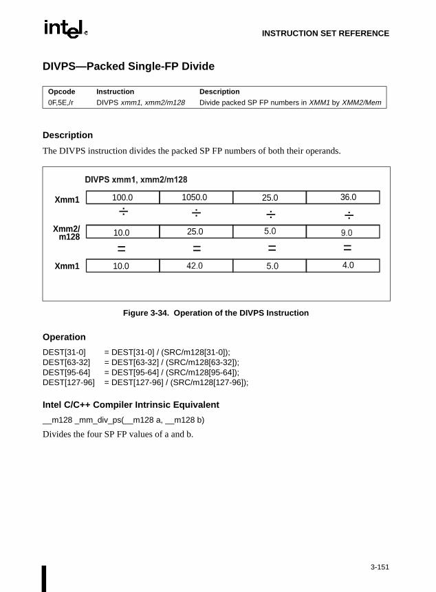
INSTRUCTION SET REFERENCE
DIVPS—Packed Single-FP Divide
Description
The DIVPS instruction divides the packed SP FP numbers of both their operands.
Figure 3-34. Operation of the DIVPS Instruction
Operation
DEST[31-0] = DEST[31-0] / (SRC/m128[31-0]);DEST[63-32] = DEST[63-32] / (SRC/m128[63-32]);DEST[95-64] = DEST[95-64] / (SRC/m128[95-64]);DEST[127-96] = DEST[127-96] / (SRC/m128[127-96]);
Intel C/C++ Compiler Intrinsic Equivalent
__m128 _mm_div_ps(__m128 a, __m128 b)
Divides the four SP FP values of a and b.
Opcode Instruction Description
0F,5E,/r DIVPS xmm1, xmm2/m128 Divide packed SP FP numbers in XMM1 by XMM2/Mem
Xmm1 4.0
÷ ÷ ÷ ÷Xmm1
Xmm2/m128
100.0 1050.0
10.0 25.0
25.0 36.0
10.0
= = = =
3-151

INSTRUCTION SET REFERENCE
DIVPS—Packed Single-FP Divide (Continued)
Exceptions
General protection exception if not aligned on 16-byte boundary, regardless of segment.
Numeric Exceptions
Overflow, Underflow, Invalid, Divide by Zero, Precision, Denormal.
Protected Mode Exceptions
#GP If a memory operand effective address is outside the CS, DS, ES, FS, orGS segment limit.
#GP (0) for an illegal memory operand effective address in the CS, DS, ES, FS,or GS segments.
#SS (0) for an illegal address in the SS segment.
#PF (fault-code) for a page fault.
#UD If CR0.EM = 1.
#NM If TS bit in CR0 is set.
#XM For an unmasked Streaming SIMD Extension numeric exception(CR4.OSXMMEXCPT =1)
#UD For an unmasked Streaming SIMD Extension numeric exception(CR4.OSXMMEXCPT =0).
#UD If CR4.OSFXSR(bit 9) = 0.
#UD If CPUID.XMM(EDX bit 25) = 0.
3-152
INSTRUCTION SET REFERENCE
DIVPS—Packed Single-FP Divide (Continued)
Real Address Mode Exceptions
Interrupt 13 If any part of the operand would lie outside of the effective address spacefrom 0 to 0FFFFH.
#UD If CR0.EM = 1.
#NM If TS bit in CR0 is set.
#XM For an unmasked Streaming SIMD Extension numeric exception(CR4.OSXMMEXCPT =1).
#UD For an unmasked Streaming SIMD Extension numeric exception(CR4.OSXMMEXCPT =0).
#UD If CR4.OSFXSR(bit 9) = 0.
#UD If CPUID.XMM(EDX bit 25) = 0.
Virtual 8086 Mode Exceptions
Same exceptions as in Real Address Mode.
#PF(fault-code). If a page fault occurs.
3-153
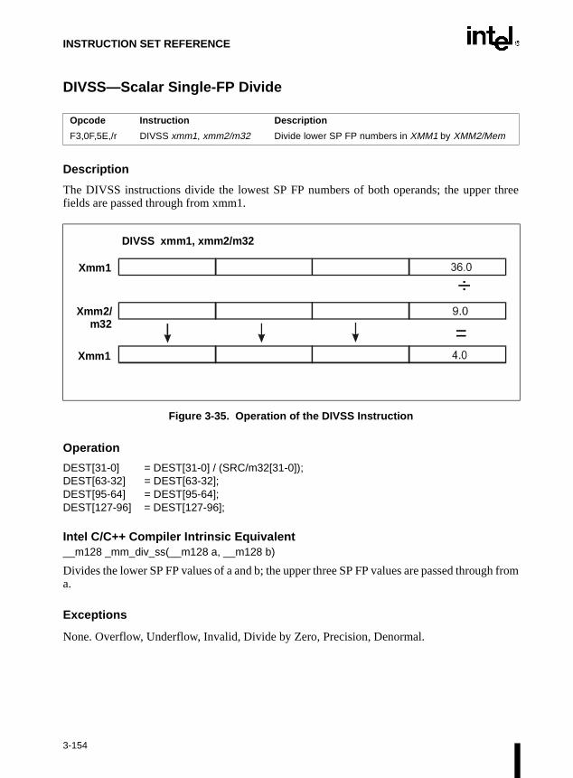
INSTRUCTION SET REFERENCE
DIVSS—Scalar Single-FP Divide
Description
The DIVSS instructions divide the lowest SP FP numbers of both operands; the upper threefields are passed through from xmm1.
Figure 3-35. Operation of the DIVSS Instruction
Operation
DEST[31-0] = DEST[31-0] / (SRC/m32[31-0]);DEST[63-32] = DEST[63-32];DEST[95-64] = DEST[95-64];DEST[127-96] = DEST[127-96];
Intel C/C++ Compiler Intrinsic Equivalent__m128 _mm_div_ss(__m128 a, __m128 b)
Divides the lower SP FP values of a and b; the upper three SP FP values are passed through froma.
Exceptions
None. Overflow, Underflow, Invalid, Divide by Zero, Precision, Denormal.
Opcode Instruction Description
F3,0F,5E,/r DIVSS xmm1, xmm2/m32 Divide lower SP FP numbers in XMM1 by XMM2/Mem
=
÷Xmm1
Xmm2/m32
Xmm1
DIVSS xmm1, xmm2/m32
3-154

INSTRUCTION SET REFERENCE
DIVSS—Scalar Single-FP Divide (Continued)
Protected Mode Exceptions
#GP(0) For an illegal memory operand effective address in the CS, DS, ES, FS, or GS segments.
#SS(0) For an illegal address in the SS segment.
#PF (fault-code) For a page fault.
#UD If CR0.EM = 1.
#NM If TS bit in CR0 is set.
#AC For unaligned memory reference. To enable #AC exceptions, three condi-tions must be true(CR0.AM is set; EFLAGS.AC is set; current CPL is 3).
#XM For an unmasked Streaming SIMD Extension numeric exception(CR4.OSXMMEXCPT =1).
#UD For an unmasked Streaming SIMD Extension numeric exception(CR4.OSXMMEXCPT =0).
#UD If CR4.OSFXSR(bit 9) = 0.
#UD If CPUID.XMM(EDX bit 25) = 0.
Real Address Mode Exceptions
Interrupt 13 If any part of the operand would lie outside of the effective address spacefrom 0 to 0FFFFH.
#UD If CR0.EM = 1.
#NM If TS bit in CR0 is set.
#XM For an unmasked Streaming SIMD Extension numeric exception(CR4.OSXMMEXCPT =1).
#UD For an unmasked Streaming SIMD Extension numeric exception(CR4.OSXMMEXCPT =0).
#UD If CR4.OSFXSR(bit 9) = 0.
#UD If CPUID.XMM(EDX bit 25) = 0.
Virtual 8086 Mode Exceptions
Same exceptions as in Real Address Mode.
#AC For unaligned memory reference if the current privilege level is 3.
#PF (fault-code) For a page fault.
3-155

INSTRUCTION SET REFERENCE
sed by
ord
of allmay
n theating-ult.
EMMS—Empty MMX™ State
Description
This instruction sets the values of all the tags in the FPU tag word to empty (all ones). This oper-ation marks the MMX™ technology registers as available, so they can subsequently be ufloating-point instructions. Refer to Figure 7-11 in Chapter 7, Floating-Point Unit of the IntelArchitecture Software Developer’s Manual, Volume 1, for the format of the FPU tag word. Allother MMX™ instructions (other than the EMMS instruction) set all the tags in FPU tag wto valid (all zeroes).
The EMMS instruction must be used to clear the MMX™ technology state at the end MMX™ technology routines and before calling other procedures or subroutines that execute floating-point instructions. If a floating-point instruction loads one of the registers iFPU register stack before the FPU tag word has been reset by the EMMS instruction, a flopoint stack overflow can occur that will result in a floating-point exception or incorrect res
OperationFPUTagWord ← FFFF
Intel C/C++ Compiler Intrinsic Equivalent
Pre-4.0 Intel C/C++ Compiler intrinsic:
void_m_empty()
Version 4.0 and later Intel C/C++ Compiler intrinsic:
void_mm_empty()
Clears the MMX™ technology state.
Flags Affected
None.
Protected Mode Exceptions
#UD If EM in CR0 is set.
#NM If TS in CR0 is set.
#MF If there is a pending FPU exception.
Opcode Instruction Description
0F 77 EMMS Set the FP tag word to empty.
3-156

INSTRUCTION SET REFERENCE
EMMS—Empty MMX™ State (Continued)
Real-Address Mode Exceptions
#UD If EM in CR0 is set.
#NM If TS in CR0 is set.
#MF If there is a pending FPU exception.
Virtual-8086 Mode Exceptions
#UD If EM in CR0 is set.
#NM If TS in CR0 is set.
#MF If there is a pending FPU exception.
3-157
INSTRUCTION SET REFERENCE
these
ecifiesointer.
uredduresed at
to theads theesting
beforee with
ENTER—Make Stack Frame for Procedure Parameters
Description
This instruction creates a stack frame for a procedure. The first operand (size operand) specifiesthe size of the stack frame (that is, the number of bytes of dynamic storage allocated on the stackfor the procedure). The second operand (nesting level operand) gives the lexical nesting level (0to 31) of the procedure. The nesting level determines the number of stack frame pointers that arecopied into the “display area” of the new stack frame from the preceding frame. Both of operands are immediate values.
The stack-size attribute determines whether the BP (16 bits) or EBP (32 bits) register spthe current frame pointer and whether SP (16 bits) or ESP (32 bits) specifies the stack p
The ENTER and companion LEAVE instructions are provided to support block structlanguages. The ENTER instruction (when used) is typically the first instruction in a proceand is used to set up a new stack frame for a procedure. The LEAVE instruction is then uthe end of the procedure (just before the RET instruction) to release the stack frame.
If the nesting level is 0, the processor pushes the frame pointer from the EBP register onstack, copies the current stack pointer from the ESP register into the EBP register, and loESP register with the current stack-pointer value minus the value in the size operand. For nlevels of one or greater, the processor pushes additional frame pointers on the stackadjusting the stack pointer. These additional frame pointers provide the called proceduraccess points to other nested frames on the stack. Refer to Section 4.5., Procedure Calls forBlock-Structured Languages in Chapter 4, Procedure Calls, Interrupts, and Exceptions of theIntel Architecture Software Developer’s Manual, Volume 1, for more information about theactions of the ENTER instruction.
Opcode Instruction Description
C8 iw 00 ENTER imm16,0 Create a stack frame for a procedure
C8 iw 01 ENTER imm16,1 Create a nested stack frame for a procedure
C8 iw ib ENTER imm16,imm8 Create a nested stack frame for a procedure
3-158

INSTRUCTION SET REFERENCE
ENTER—Make Stack Frame for Procedure Parameters (Continued)
Operation
NestingLevel ← NestingLevel MOD 32IF StackSize = 32
THEN Push(EBP) ;FrameTemp ← ESP;
ELSE (* StackSize = 16*)Push(BP); FrameTemp ← SP;
FI;IF NestingLevel = 0
THEN GOTO CONTINUE;FI;IF (NestingLevel > 0)
FOR i ← 1 TO (NestingLevel − 1)DO
IF OperandSize = 32THEN
IF StackSize = 32EBP ← EBP − 4;Push([EBP]); (* doubleword push *)
ELSE (* StackSize = 16*)BP ← BP − 4;Push([BP]); (* doubleword push *)
FI;ELSE (* OperandSize = 16 *)
IF StackSize = 32THEN
EBP ← EBP − 2;Push([EBP]); (* word push *)
ELSE (* StackSize = 16*)BP ← BP − 2;Push([BP]); (* word push *)
FI;FI;
OD;IF OperandSize = 32
THEN Push(FrameTemp); (* doubleword push *)
ELSE (* OperandSize = 16 *)Push(FrameTemp); (* word push *)
FI;GOTO CONTINUE;
FI;
3-159

INSTRUCTION SET REFERENCE
ENTER—Make Stack Frame for Procedure Parameters (Continued)
CONTINUE:IF StackSize = 32
THENEBP ← FrameTempESP ← EBP − Size;
ELSE (* StackSize = 16*)BP ← FrameTempSP ← BP − Size;
FI;END;
Flags Affected
None.
Protected Mode Exceptions
#SS(0) If the new value of the SP or ESP register is outside the stack segmentlimit.
#PF(fault-code) If a page fault occurs.
Real-Address Mode Exceptions
#SS(0) If the new value of the SP or ESP register is outside the stack segmentlimit.
Virtual-8086 Mode Exceptions
#SS(0) If the new value of the SP or ESP register is outside the stack segmentlimit.
#PF(fault-code) If a page fault occurs.
3-160

INSTRUCTION SET REFERENCE
range,
arious
er-
F2XM1—Compute 2 x–1
Description
This instruction calculates the exponential value of 2 to the power of the source operand minus1. The source operand is located in register ST(0) and the result is also stored in ST(0). The valueof the source operand must lie in the range –1.0 to +1.0. If the source value is outside thisthe result is undefined.
The following table shows the results obtained when computing the exponential value of vclasses of numbers, assuming that neither overflow nor underflow occurs.
Values other than 2 can be exponentiated using the following formula:
xy = 2(y ∗ log2x)
Operation
ST(0) ← (2ST(0) − 1);
FPU Flags Affected
C1 Set to 0 if stack underflow occurred.
Indicates rounding direction if the inexact-result exception (#P) is genated: 0 = not roundup; 1 = roundup.
C0, C2, C3 Undefined.
Opcode Instruction Description
D9 F0 F2XM1 Replace ST(0) with (2ST(0) – 1)
ST(0) SRC ST(0) DEST
−1.0 to −0 −0.5 to −0
−0 −0
+0 +0
+0 to +1.0 +0 to 1.0
3-161

INSTRUCTION SET REFERENCE
F2XM1—Compute 2 x–1 (Continued)
Floating-Point Exceptions
#IS Stack underflow occurred.
#IA Source operand is an sNaN value or unsupported format.
#D Result is a denormal value.
#U Result is too small for destination format.
#P Value cannot be represented exactly in destination format.
Protected Mode Exceptions
#NM EM or TS in CR0 is set.
Real-Address Mode Exceptions
#NM EM or TS in CR0 is set.
Virtual-8086 Mode Exceptions
#NM EM or TS in CR0 is set.
3-162

INSTRUCTION SET REFERENCE
FABS—Absolute Value
Description
This instruction clears the sign bit of ST(0) to create the absolute value of the operand. Thefollowing table shows the results obtained when creating the absolute value of various classesof numbers.
NOTE:
F Means finite-real number.
Operation
ST(0) ← |ST(0)|
FPU Flags Affected
C1 Set to 0 if stack underflow occurred; otherwise, cleared to 0.
C0, C2, C3 Undefined.
Floating-Point Exceptions
#IS Stack underflow occurred.
Protected Mode Exceptions
#NM EM or TS in CR0 is set.
Opcode Instruction Description
D9 E1 FABS Replace ST with its absolute value.
ST(0) SRC ST(0) DEST
−∞ +∞
−F +F
−0 +0
+0 +0
+F +F
+∞ +∞
NaN NaN
3-163

INSTRUCTION SET REFERENCE
FABS—Absolute Value (Continued)
Real-Address Mode Exceptions
#NM EM or TS in CR0 is set.
Virtual-8086 Mode Exceptions
#NM EM or TS in CR0 is set.
3-164

INSTRUCTION SET REFERENCE
FADD/FADDP/FIADD—Add
Description
This instruction adds the destination and source operands and stores the sum in the destinationlocation. The destination operand is always an FPU register; the source operand can be a registeror a memory location. Source operands in memory can be in single-real, double-real, word-integer, or short-integer formats.
The no-operand version of the instruction adds the contents of the ST(0) register to the ST(1)register. The one-operand version adds the contents of a memory location (either a real or aninteger value) to the contents of the ST(0) register. The two-operand version, adds the contentsof the ST(0) register to the ST(i) register or vice versa. The value in ST(0) can be doubled bycoding:
FADD ST(0), ST(0);
The FADDP instructions perform the additional operation of popping the FPU register stackafter storing the result. To pop the register stack, the processor marks the ST(0) register as emptyand increments the stack pointer (TOP) by 1. (The no-operand version of the floating-point addinstructions always results in the register stack being popped. In some assemblers, themnemonic for this instruction is FADD rather than FADDP.)
The FIADD instructions convert an integer source operand to extended-real format beforeperforming the addition.
The table on the following page shows the results obtained when adding various classes ofnumbers, assuming that neither overflow nor underflow occurs.
When the sum of two operands with opposite signs is 0, the result is +0, except for the roundtoward −∞ mode, in which case the result is −0. When the source operand is an integer 0, it istreated as a +0.
When both operand are infinities of the same sign, the result is ∞ of the expected sign. If bothoperands are infinities of opposite signs, an invalid-operation exception is generated.
Opcode Instruction Description
D8 /0 FADD m32 real Add m32real to ST(0) and store result in ST(0)
DC /0 FADD m64real Add m64real to ST(0) and store result in ST(0)
D8 C0+i FADD ST(0), ST(i) Add ST(0) to ST(i) and store result in ST(0)
DC C0+i FADD ST(i), ST(0) Add ST(i) to ST(0) and store result in ST(i)
DE C0+i FADDP ST(i), ST(0) Add ST(0) to ST(i), store result in ST(i), and pop the register stack
DE C1 FADDP Add ST(0) to ST(1), store result in ST(1), and pop the register stack
DA /0 FIADD m32int Add m32int to ST(0) and store result in ST(0)
DE /0 FIADD m16int Add m16int to ST(0) and store result in ST(0)
3-165
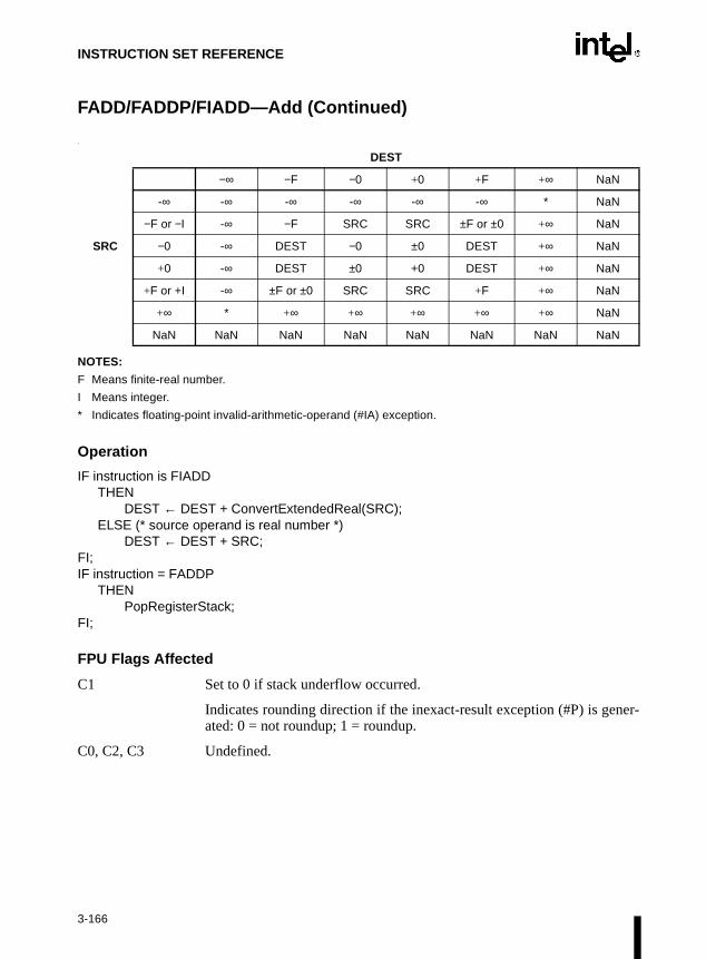
INSTRUCTION SET REFERENCE
FADD/FADDP/FIADD—Add (Continued)
.
NOTES:
F Means finite-real number.
I Means integer.
* Indicates floating-point invalid-arithmetic-operand (#IA) exception.
Operation
IF instruction is FIADDTHEN
DEST ← DEST + ConvertExtendedReal(SRC);ELSE (* source operand is real number *)
DEST ← DEST + SRC;FI;IF instruction = FADDP
THEN PopRegisterStack;
FI;
FPU Flags Affected
C1 Set to 0 if stack underflow occurred.
Indicates rounding direction if the inexact-result exception (#P) is gener-ated: 0 = not roundup; 1 = roundup.
C0, C2, C3 Undefined.
DEST
−∞ −F −0 +0 +F +∞ NaN
-∞ -∞ -∞ -∞ -∞ -∞ * NaN
−F or −I -∞ −F SRC SRC ±F or ±0 +∞ NaN
SRC −0 -∞ DEST −0 ±0 DEST +∞ NaN
+0 -∞ DEST ±0 +0 DEST +∞ NaN
+F or +I -∞ ±F or ±0 SRC SRC +F +∞ NaN
+∞ * +∞ +∞ +∞ +∞ +∞ NaN
NaN NaN NaN NaN NaN NaN NaN NaN
3-166

INSTRUCTION SET REFERENCE
FADD/FADDP/FIADD—Add (Continued)
Floating-Point Exceptions
#IS Stack underflow occurred.
#IA Operand is an sNaN value or unsupported format.
Operands are infinities of unlike sign.
#D Source operand is a denormal value.
#U Result is too small for destination format.
#O Result is too large for destination format.
#P Value cannot be represented exactly in destination format.
Protected Mode Exceptions
#GP(0) If a memory operand effective address is outside the CS, DS, ES, FS, orGS segment limit.
If the DS, ES, FS, or GS register contains a null segment selector.
#SS(0) If a memory operand effective address is outside the SS segment limit.
#NM EM or TS in CR0 is set.
#PF(fault-code) If a page fault occurs.
#AC(0) If alignment checking is enabled and an unaligned memory reference ismade while the current privilege level is 3.
Real-Address Mode Exceptions
#GP If a memory operand effective address is outside the CS, DS, ES, FS, orGS segment limit.
#SS If a memory operand effective address is outside the SS segment limit.
#NM EM or TS in CR0 is set.
3-167

INSTRUCTION SET REFERENCE
FADD/FADDP/FIADD—Add (Continued)
Virtual-8086 Mode Exceptions
#GP(0) If a memory operand effective address is outside the CS, DS, ES, FS, orGS segment limit.
#SS(0) If a memory operand effective address is outside the SS segment limit.
#NM EM or TS in CR0 is set.
#PF(fault-code) If a page fault occurs.
#AC(0) If alignment checking is enabled and an unaligned memory reference ismade.
3-168
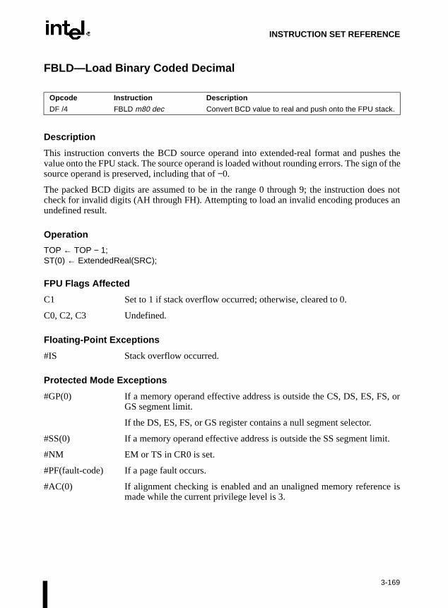
INSTRUCTION SET REFERENCE
FBLD—Load Binary Coded Decimal
Description
This instruction converts the BCD source operand into extended-real format and pushes thevalue onto the FPU stack. The source operand is loaded without rounding errors. The sign of thesource operand is preserved, including that of −0.
The packed BCD digits are assumed to be in the range 0 through 9; the instruction does notcheck for invalid digits (AH through FH). Attempting to load an invalid encoding produces anundefined result.
Operation
TOP ← TOP − 1;ST(0) ← ExtendedReal(SRC);
FPU Flags Affected
C1 Set to 1 if stack overflow occurred; otherwise, cleared to 0.
C0, C2, C3 Undefined.
Floating-Point Exceptions
#IS Stack overflow occurred.
Protected Mode Exceptions
#GP(0) If a memory operand effective address is outside the CS, DS, ES, FS, orGS segment limit.
If the DS, ES, FS, or GS register contains a null segment selector.
#SS(0) If a memory operand effective address is outside the SS segment limit.
#NM EM or TS in CR0 is set.
#PF(fault-code) If a page fault occurs.
#AC(0) If alignment checking is enabled and an unaligned memory reference ismade while the current privilege level is 3.
Opcode Instruction Description
DF /4 FBLD m80 dec Convert BCD value to real and push onto the FPU stack.
3-169

INSTRUCTION SET REFERENCE
FBLD—Load Binary Coded Decimal (Continued)
Real-Address Mode Exceptions
#GP If a memory operand effective address is outside the CS, DS, ES, FS, orGS segment limit.
#SS If a memory operand effective address is outside the SS segment limit.
#NM EM or TS in CR0 is set.
Virtual-8086 Mode Exceptions
#GP(0) If a memory operand effective address is outside the CS, DS, ES, FS, orGS segment limit.
#SS(0) If a memory operand effective address is outside the SS segment limit.
#NM EM or TS in CR0 is set.
#PF(fault-code) If a page fault occurs.
#AC(0) If alignment checking is enabled and an unaligned memory reference ismade.
3-170

INSTRUCTION SET REFERENCE
FBSTP—Store BCD Integer and Pop
Description
This instruction converts the value in the ST(0) register to an 18-digit packed BCD integer,stores the result in the destination operand, and pops the register stack. If the source value is anon-integral value, it is rounded to an integer value, according to rounding mode specified bythe RC field of the FPU control word. To pop the register stack, the processor marks the ST(0)register as empty and increments the stack pointer (TOP) by 1.
The destination operand specifies the address where the first byte destination value is to bestored. The BCD value (including its sign bit) requires 10 bytes of space in memory.
The following table shows the results obtained when storing various classes of numbers inpacked BCD format.
NOTES:
F Means finite-real number.
D Means packed-BCD number.
* Indicates floating-point invalid-operation (#IA) exception.
** ±0 or ±1, depending on the rounding mode.
If the source value is too large for the destination format and the invalid-operation exception isnot masked, an invalid-operation exception is generated and no value is stored in the destinationoperand. If the invalid-operation exception is masked, the packed BCD indefinite value is storedin memory.
If the source value is a quiet NaN, an invalid-operation exception is generated. Quiet NaNs donot normally cause this exception to be generated.
Opcode Instruction Description
DF /6 FBSTP m80bcd Store ST(0) in m80bcd and pop ST(0).
ST(0) DEST
-∞ *
−F < −1 −D
−1 < −F < −0 **
−0 −0
+0 +0
+0 < +F < +1 **
+F > +1 +D
+∞ *
NaN *
3-171

INSTRUCTION SET REFERENCE
FBSTP—Store BCD Integer and Pop (Continued)
Operation
DEST ← BCD(ST(0));PopRegisterStack;
FPU Flags Affected
C1 Set to 0 if stack underflow occurred.
Indicates rounding direction if the inexact exception (#P) is generated:0 = not roundup; 1 = roundup.
C0, C2, C3 Undefined.
Floating-Point Exceptions
#IS Stack underflow occurred.
#IA Source operand is empty; contains a NaN, ±∞, or unsupported format; orcontains value that exceeds 18 BCD digits in length.
#P Value cannot be represented exactly in destination format.
Protected Mode Exceptions
#GP(0) If a segment register is being loaded with a segment selector that points toa nonwritable segment.
If a memory operand effective address is outside the CS, DS, ES, FS, orGS segment limit.
If the DS, ES, FS, or GS register contains a null segment selector.
#SS(0) If a memory operand effective address is outside the SS segment limit.
#NM EM or TS in CR0 is set.
#PF(fault-code) If a page fault occurs.
#AC(0) If alignment checking is enabled and an unaligned memory reference ismade while the current privilege level is 3.
Real-Address Mode Exceptions
#GP If a memory operand effective address is outside the CS, DS, ES, FS, orGS segment limit.
#SS If a memory operand effective address is outside the SS segment limit.
#NM EM or TS in CR0 is set.
3-172

INSTRUCTION SET REFERENCE
FBSTP—Store BCD Integer and Pop (Continued)
Virtual-8086 Mode Exceptions
#GP(0) If a memory operand effective address is outside the CS, DS, ES, FS, orGS segment limit.
#SS(0) If a memory operand effective address is outside the SS segment limit.
#NM EM or TS in CR0 is set.
#PF(fault-code) If a page fault occurs.
#AC(0) If alignment checking is enabled and an unaligned memory reference ismade.
3-173

INSTRUCTION SET REFERENCE
FCHS—Change Sign
Description
This instruction complements the sign bit of ST(0). This operation changes a positive value intoa negative value of equal magnitude or vice versa. The following table shows the resultsobtained when changing the sign of various classes of numbers.
NOTE:
F Means finite-real number.
Operation
SignBit(ST(0)) ← NOT (SignBit(ST(0)))
FPU Flags Affected
C1 Set to 0 if stack underflow occurred; otherwise, cleared to 0.
C0, C2, C3 Undefined.
Floating-Point Exceptions
#IS Stack underflow occurred.
Protected Mode Exceptions
#NM EM or TS in CR0 is set.
Opcode Instruction Description
D9 E0 FCHS Complements sign of ST(0)
ST(0) SRC ST(0) DEST
−∞ +∞
−F +F
−0 +0
+0 −0
+F −F
+∞ −∞
NaN NaN
3-174

INSTRUCTION SET REFERENCE
FCHS—Change Sign (Continued)
Real-Address Mode Exceptions
#NM EM or TS in CR0 is set.
Virtual-8086 Mode Exceptions
#NM EM or TS in CR0 is set.
3-175

INSTRUCTION SET REFERENCE
isior to
FCLEX/FNCLEX—Clear Exceptions
NOTE:
* Refer to “Intel Architecture Compatibility” below.
Description
This instruction clears the floating-point exception flags (PE, UE, OE, ZE, DE, and IE), theexception summary status flag (ES), the stack fault flag (SF), and the busy flag (B) in the FPUstatus word. The FCLEX instruction checks for and handles any pending unmasked floating-point exceptions before clearing the exception flags; the FNCLEX instruction does not.
Intel Architecture Compatibility
When operating a Pentium® or Intel486™ processor in MS-DOS compatibility mode, it possible (under unusual circumstances) for an FNCLEX instruction to be interrupted prbeing executed to handle a pending FPU exception. Refer to Section D.2.1.3., No-Wait FPUInstructions Can Get FPU Interrupt in Window in Appendix D, Guidelines for Writing FPU andStreaming SIMD Extension Exception Handlers of the Intel Architecture Software Developer’sManual, Volume 1, for a description of these circumstances. An FNCLEX instruction cannot beinterrupted in this way on a Pentium® Pro processor.
On a Pentium® III processor, the FCLEX/FNCLEX instructions operate the same as on aPentium® II processor. They have no effect on the Pentium® III processor SIMD floating-pointfunctional unit or control/status register.
Operation
FPUStatusWord[0..7] ← 0;FPUStatusWord[15] ← 0;
FPU Flags Affected
The PE, UE, OE, ZE, DE, IE, ES, SF, and B flags in the FPU status word are cleared. The C0,C1, C2, and C3 flags are undefined.
Floating-Point Exceptions
None.
Opcode Instruction Description
9B DB E2 FCLEX Clear floating-point exception flags after checking for pending unmasked floating-point exceptions.
DB E2 FNCLEX* Clear floating-point exception flags without checking for pending unmasked floating-point exceptions.
3-176

INSTRUCTION SET REFERENCE
FCLEX/FNCLEX—Clear Exceptions (Continued)
Protected Mode Exceptions
#NM EM or TS in CR0 is set.
Real-Address Mode Exceptions
#NM EM or TS in CR0 is set.
Virtual-8086 Mode Exceptions
#NM EM or TS in CR0 is set.
3-177
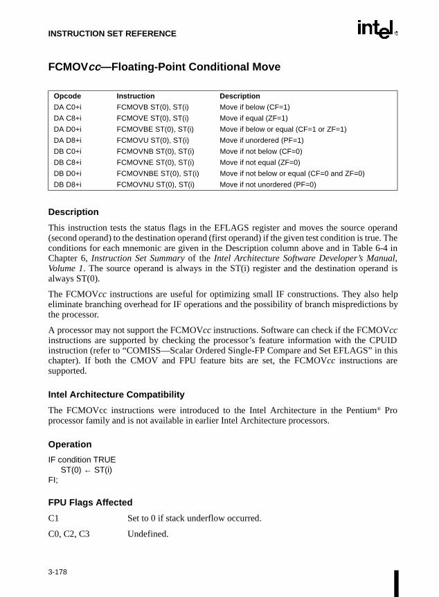
INSTRUCTION SET REFERENCE
l,
UID this
FCMOVcc—Floating-Point Conditional Move
Description
This instruction tests the status flags in the EFLAGS register and moves the source operand(second operand) to the destination operand (first operand) if the given test condition is true. Theconditions for each mnemonic are given in the Description column above and in Table 6-4 inChapter 6, Instruction Set Summary of the Intel Architecture Software Developer’s ManuaVolume 1. The source operand is always in the ST(i) register and the destination operand isalways ST(0).
The FCMOVcc instructions are useful for optimizing small IF constructions. They also helpeliminate branching overhead for IF operations and the possibility of branch mispredictions bythe processor.
A processor may not support the FCMOVcc instructions. Software can check if the FCMOVccinstructions are supported by checking the processor’s feature information with the CPinstruction (refer to “COMISS—Scalar Ordered Single-FP Compare and Set EFLAGS” inchapter). If both the CMOV and FPU feature bits are set, the FCMOVcc instructions aresupported.
Intel Architecture Compatibility
The FCMOVcc instructions were introduced to the Intel Architecture in the Pentium® Proprocessor family and is not available in earlier Intel Architecture processors.
Operation
IF condition TRUEST(0) ← ST(i)
FI;
FPU Flags Affected
C1 Set to 0 if stack underflow occurred.
C0, C2, C3 Undefined.
Opcode Instruction Description
DA C0+i FCMOVB ST(0), ST(i) Move if below (CF=1)
DA C8+i FCMOVE ST(0), ST(i) Move if equal (ZF=1)
DA D0+i FCMOVBE ST(0), ST(i) Move if below or equal (CF=1 or ZF=1)
DA D8+i FCMOVU ST(0), ST(i) Move if unordered (PF=1)
DB C0+i FCMOVNB ST(0), ST(i) Move if not below (CF=0)
DB C8+i FCMOVNE ST(0), ST(i) Move if not equal (ZF=0)
DB D0+i FCMOVNBE ST(0), ST(i) Move if not below or equal (CF=0 and ZF=0)
DB D8+i FCMOVNU ST(0), ST(i) Move if not unordered (PF=0)
3-178

INSTRUCTION SET REFERENCE
FCMOVcc—Floating-Point Conditional Move (Continued)
Floating-Point Exceptions
#IS Stack underflow occurred.
Integer Flags Affected
None.
Protected Mode Exceptions
#NM EM or TS in CR0 is set.
Real-Address Mode Exceptions
#NM EM or TS in CR0 is set.
Virtual-8086 Mode Exceptions
#NM EM or TS in CR0 is set.
3-179

INSTRUCTION SET REFERENCE
ine”etic-
set toflags
d the pop
e stack
FCOM/FCOMP/FCOMPP—Compare Real
Description
These instructions compare the contents of register ST(0) and source value and sets conditioncode flags C0, C2, and C3 in the FPU status word according to the results (refer to the tablebelow). The source operand can be a data register or a memory location. If no source operand isgiven, the value in ST(0) is compared with the value in ST(1). The sign of zero is ignored, sothat –0.0 = +0.0.
NOTE:
* Flags not set if unmasked invalid-arithmetic-operand (#IA) exception is generated.
This instruction checks the class of the numbers being compared (refer to “FXAM—Examin this chapter). If either operand is a NaN or is in an unsupported format, an invalid-arithmoperand exception (#IA) is raised and, if the exception is masked, the condition flags are“unordered.” If the invalid-arithmetic-operand exception is unmasked, the condition code are not set.
The FCOMP instruction pops the register stack following the comparison operation anFCOMPP instruction pops the register stack twice following the comparison operation. Tothe register stack, the processor marks the ST(0) register as empty and increments thpointer (TOP) by 1.
Opcode Instruction Description
D8 /2 FCOM m32real Compare ST(0) with m32real.
DC /2 FCOM m64real Compare ST(0) with m64real.
D8 D0+i FCOM ST(i) Compare ST(0) with ST(i).
D8 D1 FCOM Compare ST(0) with ST(1).
D8 /3 FCOMP m32real Compare ST(0) with m32real and pop register stack.
DC /3 FCOMP m64real Compare ST(0) with m64real and pop register stack.
D8 D8+i FCOMP ST(i) Compare ST(0) with ST(i) and pop register stack.
D8 D9 FCOMP Compare ST(0) with ST(1) and pop register stack.
DE D9 FCOMPP Compare ST(0) with ST(1) and pop register stack twice.
Condition C3 C2 C0
ST(0) > SRC 0 0 0
ST(0) < SRC 0 0 1
ST(0) = SRC 1 0 0
Unordered* 1 1 1
3-180

INSTRUCTION SET REFERENCE
FCOM/FCOMP/FCOMPP—Compare Real (Continued)
The FCOM instructions perform the same operation as the FUCOM instructions. The onlydifference is how they handle qNaN operands. The FCOM instructions raise an invalid-arith-metic-operand exception (#IA) when either or both of the operands is a NaN value or is in anunsupported format. The FUCOM instructions perform the same operation as the FCOMinstructions, except that they do not generate an invalid-arithmetic-operand exception forqNaNs.
Operation
CASE (relation of operands) OFST > SRC: C3, C2, C0 ← 000;ST < SRC: C3, C2, C0 ← 001;ST = SRC: C3, C2, C0 ← 100;
ESAC;IF ST(0) or SRC = NaN or unsupported format
THEN #IAIF FPUControlWord.IM = 1
THEN C3, C2, C0 ← 111;
FI;FI;IF instruction = FCOMP
THEN PopRegisterStack;
FI;IF instruction = FCOMPP
THEN PopRegisterStack;PopRegisterStack;
FI;
FPU Flags Affected
C1 Set to 0 if stack underflow occurred; otherwise, cleared to 0.
C0, C2, C3 Refer to table on previous page.
Floating-Point Exceptions
#IS Stack underflow occurred.
#IA One or both operands are NaN values or have unsupported formats.
Register is marked empty.
#D One or both operands are denormal values.
3-181

INSTRUCTION SET REFERENCE
FCOM/FCOMP/FCOMPP—Compare Real (Continued)
Protected Mode Exceptions
#GP(0) If a memory operand effective address is outside the CS, DS, ES, FS, orGS segment limit.
If the DS, ES, FS, or GS register contains a null segment selector.
#SS(0) If a memory operand effective address is outside the SS segment limit.
#NM EM or TS in CR0 is set.
#PF(fault-code) If a page fault occurs.
#AC(0) If alignment checking is enabled and an unaligned memory reference ismade while the current privilege level is 3.
Real-Address Mode Exceptions
#GP If a memory operand effective address is outside the CS, DS, ES, FS, orGS segment limit.
#SS If a memory operand effective address is outside the SS segment limit.
#NM EM or TS in CR0 is set.
Virtual-8086 Mode Exceptions
#GP(0) If a memory operand effective address is outside the CS, DS, ES, FS, orGS segment limit.
#SS(0) If a memory operand effective address is outside the SS segment limit.
#NM EM or TS in CR0 is set.
#PF(fault-code) If a page fault occurs.
#AC(0) If alignment checking is enabled and an unaligned memory reference ismade.
3-182

INSTRUCTION SET REFERENCE
MIPMIPerand in an
MIPn forred
etic-
risond incre-
FCOMI/FCOMIP/ FUCOMI/FUCOMIP—Compare Real and Set EFLAGS
Description
These instructions compare the contents of register ST(0) and ST(i) and sets the status flags ZF,PF, and CF in the EFLAGS register according to the results (refer to the table below). The signof zero is ignored for comparisons, so that –0.0 = +0.0.
NOTE:
* Flags are set regardless, whether there is an unmasked invalid-arithmetic-operand (#IA) exception gen-erated or not.
The FCOMI/FCOMIP instructions perform the same operation as the FUCOMI/FUCOinstructions. The only difference is how they handle qNaN operands. The FCOMI/FCOinstructions set the status flags to “unordered” and generate an invalid-arithmetic-opexception (#IA) when either or both of the operands is a NaN value (sNaN or qNaN) or isunsupported format.
The FUCOMI/FUCOMIP instructions perform the same operation as the FCOMI/FCOinstructions, except that they do not generate an invalid-arithmetic-operand exceptioqNaNs. Refer to “FXAM—Examine” in this chapter for additional information on unordecomparisons.
If invalid-operation exception is unmasked, the status flags are not set if the invalid-arithmoperand exception is generated.
The FCOMIP and FUCOMIP instructions also pop the register stack following the compaoperation. To pop the register stack, the processor marks the ST(0) register as empty anments the stack pointer (TOP) by 1.
Opcode Instruction Description
DB F0+i FCOMI ST, ST(i) Compare ST(0) with ST(i) and set status flags accordingly
DF F0+i FCOMIP ST, ST(i) Compare ST(0) with ST(i), set status flags accordingly, and pop register stack
DB E8+i FUCOMI ST, ST(i) Compare ST(0) with ST(i), check for ordered values, and set status flags accordingly
DF E8+i FUCOMIP ST, ST(i) Compare ST(0) with ST(i), check for ordered values, set status flags accordingly, and pop register stack
Comparison Results ZF PF CF
ST0 > ST(i) 0 0 0
ST0 < ST(i) 0 0 1
ST0 = ST(i) 1 0 0
Unordered* 1 1 1
3-183

INSTRUCTION SET REFERENCE
FCOMI/FCOMIP/ FUCOMI/FUCOMIP—Compare Real and Set EFLAGS (Continued)
Intel Architecture Compatibility
The FCOMI/FCOMIP/FUCOMI/FUCOMIP instructions were introduced to the Intel Architec-ture in the Pentium® Pro processor family and are not available in earlier Intel Architectureprocessors.
Operation
CASE (relation of operands) OFST(0) > ST(i): ZF, PF, CF ← 000;ST(0) < ST(i): ZF, PF, CF ← 001;ST(0) = ST(i): ZF, PF, CF ← 100;
ESAC;IF instruction is FCOMI or FCOMIP
THENIF ST(0) or ST(i) = NaN or unsupported format
THEN #IAIF FPUControlWord.IM = 1
THEN ZF, PF, CF ← 111;
FI;FI;
FI;IF instruction is FUCOMI or FUCOMIP
THENIF ST(0) or ST(i) = QNaN, but not SNaN or unsupported format
THEN ZF, PF, CF ← 111;
ELSE (* ST(0) or ST(i) is SNaN or unsupported format *) #IA;IF FPUControlWord.IM = 1
THEN ZF, PF, CF ← 111;
FI;FI;
FI;IF instruction is FCOMIP or FUCOMIP
THEN PopRegisterStack;
FI;
3-184

INSTRUCTION SET REFERENCE
FCOMI/FCOMIP/ FUCOMI/FUCOMIP—Compare Real and Set EFLAGS (Continued)
FPU Flags Affected
C1 Set to 0 if stack underflow occurred; otherwise, cleared to 0.
C0, C2, C3 Not affected.
Floating-Point Exceptions
#IS Stack underflow occurred.
#IA (FCOMI or FCOMIP instruction) One or both operands are NaN values orhave unsupported formats.
(FUCOMI or FUCOMIP instruction) One or both operands are sNaNvalues (but not qNaNs) or have undefined formats. Detection of a qNaNvalue does not raise an invalid-operand exception.
Protected Mode Exceptions
#NM EM or TS in CR0 is set.
Real-Address Mode Exceptions
#NM EM or TS in CR0 is set.
Virtual-8086 Mode Exceptions
#NM EM or TS in CR0 is set.
3-185
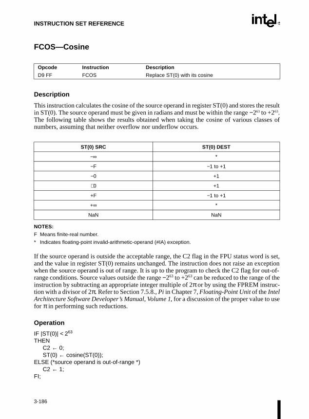
INSTRUCTION SET REFERENCE
FCOS—Cosine
Description
This instruction calculates the cosine of the source operand in register ST(0) and stores the resultin ST(0). The source operand must be given in radians and must be within the range −263 to +263.The following table shows the results obtained when taking the cosine of various classes ofnumbers, assuming that neither overflow nor underflow occurs.
NOTES:
F Means finite-real number.
* Indicates floating-point invalid-arithmetic-operand (#IA) exception.
If the source operand is outside the acceptable range, the C2 flag in the FPU status word is set,and the value in register ST(0) remains unchanged. The instruction does not raise an exceptionwhen the source operand is out of range. It is up to the program to check the C2 flag for out-of-range conditions. Source values outside the range −263 to +263 can be reduced to the range of theinstruction by subtracting an appropriate integer multiple of 2π or by using the FPREM instruc-tion with a divisor of 2π. Refer to Section 7.5.8., Pi in Chapter 7, Floating-Point Unit of the IntelArchitecture Software Developer’s Manual, Volume 1, for a discussion of the proper value to usefor π in performing such reductions.
Operation
IF |ST(0)| < 263
THENC2 ← 0;ST(0) ← cosine(ST(0));
ELSE (*source operand is out-of-range *)C2 ← 1;
FI;
Opcode Instruction Description
D9 FF FCOS Replace ST(0) with its cosine
ST(0) SRC ST(0) DEST
−∞ *
−F −1 to +1
−0 +1
+0 +1
+F −1 to +1
+∞ *
NaN NaN
3-186

INSTRUCTION SET REFERENCE
FCOS—Cosine (Continued)
FPU Flags Affected
C1 Set to 0 if stack underflow occurred.
Indicates rounding direction if the inexact-result exception (#P) is gener-ated: 0 = not roundup; 1 = roundup.
Undefined if C2 is 1.
C2 Set to 1 if source operand is outside the range −263 to +263; otherwise,cleared to 0.
C0, C3 Undefined.
Floating-Point Exceptions
#IS Stack underflow occurred.
#IA Source operand is an sNaN value, ∞, or unsupported format.
#D Result is a denormal value.
#U Result is too small for destination format.
#P Value cannot be represented exactly in destination format.
Protected Mode Exceptions
#NM EM or TS in CR0 is set.
Real-Address Mode Exceptions
#NM EM or TS in CR0 is set.
Virtual-8086 Mode Exceptions
#NM EM or TS in CR0 is set.
3-187

INSTRUCTION SET REFERENCE
FDECSTP—Decrement Stack-Top Pointer
Description
Description
This instruction subtracts one from the TOP field of the FPU status word (decrements the top-of-stack pointer). If the TOP field contains a 0, it is set to 7. The effect of this instruction is torotate the stack by one position. The contents of the FPU data registers and tag register are notaffected.
Operation
IF TOP = 0THEN TOP ← 7;ELSE TOP ← TOP – 1;
FI;
FPU Flags Affected
The C1 flag is set to 0; otherwise, cleared to 0. The C0, C2, and C3 flags are undefined.
Floating-Point Exceptions
None.
Protected Mode Exceptions
#NM EM or TS in CR0 is set.
Real-Address Mode Exceptions
#NM EM or TS in CR0 is set.
Virtual-8086 Mode Exceptions
#NM EM or TS in CR0 is set.
Opcode Instruction Description
D9 F6 FDECSTP Decrement TOP field in FPU status word.
3-188

INSTRUCTION SET REFERENCE
FDIV/FDIVP/FIDIV—Divide
Description
These instructions divide the destination operand by the source operand and stores the result inthe destination location. The destination operand (dividend) is always in an FPU register; thesource operand (divisor) can be a register or a memory location. Source operands in memorycan be in single-real, double-real, word-integer, or short-integer formats.
The no-operand version of the instruction divides the contents of the ST(1) register by thecontents of the ST(0) register. The one-operand version divides the contents of the ST(0) registerby the contents of a memory location (either a real or an integer value). The two-operandversion, divides the contents of the ST(0) register by the contents of the ST(i) register or viceversa.
The FDIVP instructions perform the additional operation of popping the FPU register stack afterstoring the result. To pop the register stack, the processor marks the ST(0) register as empty andincrements the stack pointer (TOP) by 1. The no-operand version of the floating-point divideinstructions always results in the register stack being popped. In some assemblers, themnemonic for this instruction is FDIV rather than FDIVP.
The FIDIV instructions convert an integer source operand to extended-real format beforeperforming the division. When the source operand is an integer 0, it is treated as a +0.
If an unmasked divide by zero exception (#Z) is generated, no result is stored; if the exceptionis masked, an ∞ of the appropriate sign is stored in the destination operand.
The following table shows the results obtained when dividing various classes of numbers,assuming that neither overflow nor underflow occurs.
Opcode Instruction Description
D8 /6 FDIV m32real Divide ST(0) by m32real and store result in ST(0)
DC /6 FDIV m64real Divide ST(0) by m64real and store result in ST(0)
D8 F0+i FDIV ST(0), ST(i) Divide ST(0) by ST(i) and store result in ST(0)
DC F8+i FDIV ST(i), ST(0) Divide ST(i) by ST(0) and store result in ST(i)
DE F8+i FDIVP ST(i), ST(0) Divide ST(i) by ST(0), store result in ST(i), and pop the register stack
DE F9 FDIVP Divide ST(1) by ST(0), store result in ST(1), and pop the register stack
DA /6 FIDIV m32int Divide ST(0) by m32int and store result in ST(0)
DE /6 FIDIV m16int Divide ST(0) by m16int and store result in ST(0)
3-189

INSTRUCTION SET REFERENCE
FDIV/FDIVP/FIDIV—Divide (Continued)
NOTES:
F Means finite-real number.
I Means integer.
* Indicates floating-point invalid-arithmetic-operand (#IA) exception.
** Indicates floating-point zero-divide (#Z) exception.
Operation
IF SRC = 0THEN
#ZELSE
IF instruction is FIDIVTHEN
DEST ← DEST / ConvertExtendedReal(SRC);ELSE (* source operand is real number *)
DEST ← DEST / SRC;FI;
FI;IF instruction = FDIVP
THEN PopRegisterStack
FI;
DEST
−∞ −F −0 +0 +F +∞ NaN
-∞ * +0 +0 −0 −0 * NaN
−F +∞ +F +0 −0 −F −∞ NaN
−I +∞ +F +0 −0 −F −∞ NaN
SRC −0 +∞ ** * * ** −∞ NaN
+0 −∞ ** * * ** +∞ NaN
+I −∞ −F −0 +0 +F +∞ NaN
+F −∞ −F −0 +0 +F +∞ NaN
+∞ * −0 −0 +0 +0 * NaN
NaN NaN NaN NaN NaN NaN NaN NaN
3-190

INSTRUCTION SET REFERENCE
FDIV/FDIVP/FIDIV—Divide (Continued)
FPU Flags Affected
C1 Set to 0 if stack underflow occurred.
Indicates rounding direction if the inexact-result exception (#P) is gener-ated: 0 = not roundup; 1 = roundup.
C0, C2, C3 Undefined.
Floating-Point Exceptions
#IS Stack underflow occurred.
#IA Operand is an sNaN value or unsupported format.
±∞ / ±∞; ±0 / ±0
#D Result is a denormal value.
#Z DEST / ±0, where DEST is not equal to ±0.
#U Result is too small for destination format.
#O Result is too large for destination format.
#P Value cannot be represented exactly in destination format.
Protected Mode Exceptions
#GP(0) If a memory operand effective address is outside the CS, DS, ES, FS, orGS segment limit.
If the DS, ES, FS, or GS register contains a null segment selector.
#SS(0) If a memory operand effective address is outside the SS segment limit.
#NM EM or TS in CR0 is set.
#PF(fault-code) If a page fault occurs.
#AC(0) If alignment checking is enabled and an unaligned memory reference ismade while the current privilege level is 3.
Real-Address Mode Exceptions
#GP If a memory operand effective address is outside the CS, DS, ES, FS, orGS segment limit.
#SS If a memory operand effective address is outside the SS segment limit.
#NM EM or TS in CR0 is set.
3-191
INSTRUCTION SET REFERENCE
FDIV/FDIVP/FIDIV—Divide (Continued)
Virtual-8086 Mode Exceptions
#GP(0) If a memory operand effective address is outside the CS, DS, ES, FS, orGS segment limit.
#SS(0) If a memory operand effective address is outside the SS segment limit.
#NM EM or TS in CR0 is set.
#PF(fault-code) If a page fault occurs.
#AC(0) If alignment checking is enabled and an unaligned memory reference ismade.
3-192

INSTRUCTION SET REFERENCE
FDIVR/FDIVRP/FIDIVR—Reverse Divide
Description
These instructions divide the source operand by the destination operand and stores the result inthe destination location. The destination operand (divisor) is always in an FPU register; thesource operand (dividend) can be a register or a memory location. Source operands in memorycan be in single-real, double-real, word-integer, or short-integer formats.
These instructions perform the reverse operations of the FDIV, FDIVP, and FIDIV instructions.They are provided to support more efficient coding.
The no-operand version of the instruction divides the contents of the ST(0) register by thecontents of the ST(1) register. The one-operand version divides the contents of a memory loca-tion (either a real or an integer value) by the contents of the ST(0) register. The two-operandversion, divides the contents of the ST(i) register by the contents of the ST(0) register or viceversa.
The FDIVRP instructions perform the additional operation of popping the FPU register stackafter storing the result. To pop the register stack, the processor marks the ST(0) register as emptyand increments the stack pointer (TOP) by 1. The no-operand version of the floating-pointdivide instructions always results in the register stack being popped. In some assemblers, themnemonic for this instruction is FDIVR rather than FDIVRP.
The FIDIVR instructions convert an integer source operand to extended-real format beforeperforming the division.
If an unmasked divide by zero exception (#Z) is generated, no result is stored; if the exceptionis masked, an ∞ of the appropriate sign is stored in the destination operand.
The following table shows the results obtained when dividing various classes of numbers,assuming that neither overflow nor underflow occurs.
Opcode Instruction Description
D8 /7 FDIVR m32real Divide m32real by ST(0) and store result in ST(0)
DC /7 FDIVR m64real Divide m64real by ST(0) and store result in ST(0)
D8 F8+i FDIVR ST(0), ST(i) Divide ST(i) by ST(0) and store result in ST(0)
DC F0+i FDIVR ST(i), ST(0) Divide ST(0) by ST(i) and store result in ST(i)
DE F0+i FDIVRP ST(i), ST(0) Divide ST(0) by ST(i), store result in ST(i), and pop the register stack
DE F1 FDIVRP Divide ST(0) by ST(1), store result in ST(1), and pop the register stack
DA /7 FIDIVR m32int Divide m32int by ST(0) and store result in ST(0)
DE /7 FIDIVR m16int Divide m16int by ST(0) and store result in ST(0)
3-193

INSTRUCTION SET REFERENCE
FDIVR/FDIVRP/FIDIVR—Reverse Divide (Continued)
NOTES:
F Means finite-real number.
I Means integer.
* Indicates floating-point invalid-arithmetic-operand (#IA) exception.
** Indicates floating-point zero-divide (#Z) exception.
When the source operand is an integer 0, it is treated as a +0.
Operation
IF DEST = 0THEN
#ZELSE
IF instruction is FIDIVRTHEN
DEST ← ConvertExtendedReal(SRC) / DEST;ELSE (* source operand is real number *)
DEST ← SRC / DEST;FI;
FI;IF instruction = FDIVRP
THEN PopRegisterStack
FI;
DEST
−∞ −F −0 +0 +F +∞ NaN
−∞ * +∞ +∞ −∞ −∞ * NaN
SRC −F +0 +F ** ** -F −0 NaN
−I +0 +F ** ** -F −0 NaN
−0 +0 +0 * * −0 −0 NaN
+0 −0 −0 * * +0 +0 NaN
+I −0 -F ** ** +F +0 NaN
+F −0 -F ** ** +F +0 NaN
+∞ * −∞ −∞ +∞ +∞ * NaN
NaN NaN NaN NaN NaN NaN NaN NaN
3-194

INSTRUCTION SET REFERENCE
FDIVR/FDIVRP/FIDIVR—Reverse Divide (Continued)
FPU Flags Affected
C1 Set to 0 if stack underflow occurred.
Indicates rounding direction if the inexact-result exception (#P) is gener-ated: 0 = not roundup; 1 = roundup.
C0, C2, C3 Undefined.
Floating-Point Exceptions
#IS Stack underflow occurred.
#IA Operand is an sNaN value or unsupported format.
±∞ / ±∞; ±0 / ±0
#D Result is a denormal value.
#Z SRC / ±0, where SRC is not equal to ±0.
#U Result is too small for destination format.
#O Result is too large for destination format.
#P Value cannot be represented exactly in destination format.
Protected Mode Exceptions
#GP(0) If a memory operand effective address is outside the CS, DS, ES, FS, orGS segment limit.
If the DS, ES, FS, or GS register contains a null segment selector.
#SS(0) If a memory operand effective address is outside the SS segment limit.
#NM EM or TS in CR0 is set.
#PF(fault-code) If a page fault occurs.
#AC(0) If alignment checking is enabled and an unaligned memory reference ismade while the current privilege level is 3.
Real-Address Mode Exceptions
#GP If a memory operand effective address is outside the CS, DS, ES, FS, orGS segment limit.
#SS If a memory operand effective address is outside the SS segment limit.
#NM EM or TS in CR0 is set.
3-195

INSTRUCTION SET REFERENCE
FDIVR/FDIVRP/FIDIVR—Reverse Divide (Continued)
Virtual-8086 Mode Exceptions
#GP(0) If a memory operand effective address is outside the CS, DS, ES, FS, orGS segment limit.
#SS(0) If a memory operand effective address is outside the SS segment limit.
#NM EM or TS in CR0 is set.
#PF(fault-code) If a page fault occurs.
#AC(0) If alignment checking is enabled and an unaligned memory reference ismade.
3-196

INSTRUCTION SET REFERENCE
FFREE—Free Floating-Point Register
Description
This instruction sets the tag in the FPU tag register associated with register ST(i) to empty (11B).The contents of ST(i) and the FPU stack-top pointer (TOP) are not affected.
Operation
TAG(i) ← 11B;
FPU Flags Affected
C0, C1, C2, C3 undefined.
Floating-Point Exceptions
None.
Protected Mode Exceptions
#NM EM or TS in CR0 is set.
Real-Address Mode Exceptions
#NM EM or TS in CR0 is set.
Virtual-8086 Mode Exceptions
#NM EM or TS in CR0 is set.
Opcode Instruction Description
DD C0+i FFREE ST(i) Sets tag for ST(i) to empty
3-197

INSTRUCTION SET REFERENCE
hecksither
gister) by 1.
FICOM/FICOMP—Compare Integer
Description
These instruction compare the value in ST(0) with an integer source operand and sets the condi-tion code flags C0, C2, and C3 in the FPU status word according to the results (refer to tablebelow). The integer value is converted to extended-real format before the comparison is made.
These instructions perform an “unordered comparison.” An unordered comparison also cthe class of the numbers being compared (refer to “FXAM—Examine” in this chapter). If eoperand is a NaN or is in an undefined format, the condition flags are set to “unordered.”
The sign of zero is ignored, so that –0.0 = +0.0.
The FICOMP instructions pop the register stack following the comparison. To pop the restack, the processor marks the ST(0) register empty and increments the stack pointer (TOP
Operation
CASE (relation of operands) OFST(0) > SRC: C3, C2, C0 ← 000;ST(0) < SRC: C3, C2, C0 ← 001;ST(0) = SRC: C3, C2, C0 ← 100;Unordered: C3, C2, C0 ← 111;
ESAC;IF instruction = FICOMP
THEN PopRegisterStack;
FI;
Opcode Instruction Description
DE /2 FICOM m16int Compare ST(0) with m16int
DA /2 FICOM m32int Compare ST(0) with m32int
DE /3 FICOMP m16int Compare ST(0) with m16int and pop stack register
DA /3 FICOMP m32int Compare ST(0) with m32int and pop stack register
Condition C3 C2 C0
ST(0) > SRC 0 0 0
ST(0) < SRC 0 0 1
ST(0) = SRC 1 0 0
Unordered 1 1 1
3-198

INSTRUCTION SET REFERENCE
FICOM/FICOMP—Compare Integer (Continued)
FPU Flags Affected
C1 Set to 0 if stack underflow occurred; otherwise, set to 0.
C0, C2, C3 Refer to table on previous page.
Floating-Point Exceptions
#IS Stack underflow occurred.
#IA One or both operands are NaN values or have unsupported formats.
#D One or both operands are denormal values.
Protected Mode Exceptions
#GP(0) If a memory operand effective address is outside the CS, DS, ES, FS, orGS segment limit.
If the DS, ES, FS, or GS register contains a null segment selector.
#SS(0) If a memory operand effective address is outside the SS segment limit.
#NM EM or TS in CR0 is set.
#PF(fault-code) If a page fault occurs.
#AC(0) If alignment checking is enabled and an unaligned memory reference ismade while the current privilege level is 3.
Real-Address Mode Exceptions
#GP If a memory operand effective address is outside the CS, DS, ES, FS, orGS segment limit.
#SS If a memory operand effective address is outside the SS segment limit.
#NM EM or TS in CR0 is set.
Virtual-8086 Mode Exceptions
#GP(0) If a memory operand effective address is outside the CS, DS, ES, FS, orGS segment limit.
#SS(0) If a memory operand effective address is outside the SS segment limit.
#NM EM or TS in CR0 is set.
#PF(fault-code) If a page fault occurs.
#AC(0) If alignment checking is enabled and an unaligned memory reference ismade.
3-199

INSTRUCTION SET REFERENCE
FILD—Load Integer
Description
This instruction converts the signed-integer source operand into extended-real format andpushes the value onto the FPU register stack. The source operand can be a word, short, or longinteger value. It is loaded without rounding errors. The sign of the source operand is preserved.
Operation
TOP ← TOP − 1;ST(0) ← ExtendedReal(SRC);
FPU Flags Affected
C1 Set to 1 if stack overflow occurred; cleared to 0 otherwise.
C0, C2, C3 Undefined.
Floating-Point Exceptions
#IS Stack overflow occurred.
Protected Mode Exceptions
#GP(0) If a memory operand effective address is outside the CS, DS, ES, FS, orGS segment limit.
If the DS, ES, FS, or GS register contains a null segment selector.
#SS(0) If a memory operand effective address is outside the SS segment limit.
#NM EM or TS in CR0 is set.
#PF(fault-code) If a page fault occurs.
#AC(0) If alignment checking is enabled and an unaligned memory reference ismade while the current privilege level is 3.
Opcode Instruction Description
DF /0 FILD m16int Push m16int onto the FPU register stack.
DB /0 FILD m32int Push m32int onto the FPU register stack.
DF /5 FILD m64int Push m64int onto the FPU register stack.
3-200
INSTRUCTION SET REFERENCE
FILD—Load Integer (Continued)
Real-Address Mode Exceptions
#GP If a memory operand effective address is outside the CS, DS, ES, FS, orGS segment limit.
#SS If a memory operand effective address is outside the SS segment limit.
#NM EM or TS in CR0 is set.
Virtual-8086 Mode Exceptions
#GP(0) If a memory operand effective address is outside the CS, DS, ES, FS, orGS segment limit.
#SS(0) If a memory operand effective address is outside the SS segment limit.
#NM EM or TS in CR0 is set.
#PF(fault-code) If a page fault occurs.
#AC(0) If alignment checking is enabled and an unaligned memory reference ismade.
3-201

INSTRUCTION SET REFERENCE
FINCSTP—Increment Stack-Top Pointer
Description
This instruction adds one to the TOP field of the FPU status word (increments the top-of-stackpointer). If the TOP field contains a 7, it is set to 0. The effect of this instruction is to rotate thestack by one position. The contents of the FPU data registers and tag register are not affected.This operation is not equivalent to popping the stack, because the tag for the previous top-of-stack register is not marked empty.
Operation
IF TOP = 7THEN TOP ← 0;ELSE TOP ← TOP + 1;
FI;
FPU Flags Affected
The C1 flag is set to 0; otherwise, cleared to 0. The C0, C2, and C3 flags are undefined.
Floating-Point Exceptions
None.
Protected Mode Exceptions
#NM EM or TS in CR0 is set.
Real-Address Mode Exceptions
#NM EM or TS in CR0 is set.
Virtual-8086 Mode Exceptions
#NM EM or TS in CR0 is set.
Opcode Instruction Description
D9 F7 FINCSTP Increment the TOP field in the FPU status register
3-202

INSTRUCTION SET REFERENCE
isor to
FINIT/FNINIT—Initialize Floating-Point Unit
NOTE:
* Refer to “Intel Architecture Compatibility” below.
Description
These instructions set the FPU control, status, tag, instruction pointer, and data pointer registersto their default states. The FPU control word is set to 037FH (round to nearest, all exceptionsmasked, 64-bit precision). The status word is cleared (no exception flags set, TOP is set to 0).The data registers in the register stack are left unchanged, but they are all tagged as empty (11B).Both the instruction and data pointers are cleared.
The FINIT instruction checks for and handles any pending unmasked floating-point exceptionsbefore performing the initialization; the FNINIT instruction does not.
Intel Architecture Compatibility
When operating a Pentium® or Intel486™ processor in MS-DOS compatibility mode, it possible (under unusual circumstances) for an FNINIT instruction to be interrupted pribeing executed to handle a pending FPU exception. Refer to Section D.2.1.3., No-Wait FPUInstructions Can Get FPU Interrupt in Window in Appendix D, Guidelines for Writing FPU andStreaming SIMD Extension Exception Handlers of the Intel Architecture Software Developer’sManual, Volume 1, for a description of these circumstances. An FNINIT instruction cannot beinterrupted in this way on a Pentium® Pro processor.
In the Intel387 math coprocessor, the FINIT/FNINIT instruction does not clear the instructionand data pointers.
On a Pentium® III processor, the FINIT/FNINT instructions operate the same as on a Pentium®
II processor. They have no effect on the Pentium® III processor SIMD floating-point functionalunit or control/status register.
Operation
FPUControlWord ← 037FH;FPUStatusWord ← 0;FPUTagWord ← FFFFH;FPUDataPointer ← 0;FPUInstructionPointer ← 0;FPULastInstructionOpcode ← 0;
Opcode Instruction Description
9B DB E3 FINIT Initialize FPU after checking for pending unmasked floating-point exceptions.
DB E3 FNINIT* Initialize FPU without checking for pending unmasked floating-point exceptions.
3-203

INSTRUCTION SET REFERENCE
FINIT/FNINIT—Initialize Floating-Point Unit (Continued)
FPU Flags Affected
C0, C1, C2, C3 cleared to 0.
Floating-Point Exceptions
None.
Protected Mode Exceptions
#NM EM or TS in CR0 is set.
Real-Address Mode Exceptions
#NM EM or TS in CR0 is set.
Virtual-8086 Mode Exceptions
#NM EM or TS in CR0 is set.
Comments
This instruction has no effect on the state of SIMD floating-point registers.
3-204

INSTRUCTION SET REFERENCE
FIST/FISTP—Store Integer
Description
The FIST instruction converts the value in the ST(0) register to a signed integer and stores theresult in the destination operand. Values can be stored in word- or short-integer format. Thedestination operand specifies the address where the first byte of the destination value is to bestored.
The FISTP instruction performs the same operation as the FIST instruction and then pops theregister stack. To pop the register stack, the processor marks the ST(0) register as empty andincrements the stack pointer (TOP) by 1. The FISTP instruction can also stores values in long-integer format.
The following table shows the results obtained when storing various classes of numbers ininteger format.
NOTES:
F Means finite-real number.
I Means integer.
* Indicates floating-point invalid-operation (#IA) exception.
** 0 or ±1, depending on the rounding mode.
Opcode Instruction Description
DF /2 FIST m16int Store ST(0) in m16int
DB /2 FIST m32int Store ST(0) in m32int
DF /3 FISTP m16int Store ST(0) in m16int and pop register stack
DB /3 FISTP m32int Store ST(0) in m32int and pop register stack
DF /7 FISTP m64int Store ST(0) in m64int and pop register stack
ST(0) DEST
−∞ *
−F < −1 −I
−1 < −F < −0 **
−0 0
+0 0
+0 < +F < +1 **
+F > +1 +I
+∞ *
NaN *
3-205

INSTRUCTION SET REFERENCE
FIST/FISTP—Store Integer (Continued)
If the source value is a non-integral value, it is rounded to an integer value, according to therounding mode specified by the RC field of the FPU control word.
If the value being stored is too large for the destination format, is an ∞, is a NaN, or is in anunsupported format and if the invalid-arithmetic-operand exception (#IA) is unmasked, aninvalid-operation exception is generated and no value is stored in the destination operand. If theinvalid-operation exception is masked, the integer indefinite value is stored in the destinationoperand.
Operation
DEST ← Integer(ST(0));IF instruction = FISTP
THEN PopRegisterStack;
FI;
FPU Flags Affected
C1 Set to 0 if stack underflow occurred.
Indicates rounding direction of if the inexact exception (#P) is generated:0 = not roundup; 1 = roundup.
Cleared to 0 otherwise.
C0, C2, C3 Undefined.
Floating-Point Exceptions
#IS Stack underflow occurred.
#IA Source operand is too large for the destination format
Source operand is a NaN value or unsupported format.
#P Value cannot be represented exactly in destination format.
3-206

INSTRUCTION SET REFERENCE
FIST/FISTP—Store Integer (Continued)
Protected Mode Exceptions
#GP(0) If the destination is located in a nonwritable segment.
If a memory operand effective address is outside the CS, DS, ES, FS, orGS segment limit.
If the DS, ES, FS, or GS register is used to access memory and it containsa null segment selector.
#SS(0) If a memory operand effective address is outside the SS segment limit.
#NM EM or TS in CR0 is set.
#PF(fault-code) If a page fault occurs.
#AC(0) If alignment checking is enabled and an unaligned memory reference ismade while the current privilege level is 3.
Real-Address Mode Exceptions
#GP If a memory operand effective address is outside the CS, DS, ES, FS, orGS segment limit.
#SS If a memory operand effective address is outside the SS segment limit.
#NM EM or TS in CR0 is set.
Virtual-8086 Mode Exceptions
#GP(0) If a memory operand effective address is outside the CS, DS, ES, FS, orGS segment limit.
#SS(0) If a memory operand effective address is outside the SS segment limit.
#NM EM or TS in CR0 is set.
#PF(fault-code) If a page fault occurs.
#AC(0) If alignment checking is enabled and an unaligned memory reference ismade.
3-207

INSTRUCTION SET REFERENCE
FLD—Load Real
Description
This instruction pushes the source operand onto the FPU register stack. If the source operand isin single- or double-real format, it is automatically converted to the extended-real format beforebeing pushed on the stack.
The FLD instruction can also push the value in a selected FPU register [ST(i)] onto the stack.Here, pushing register ST(0) duplicates the stack top.
Operation
IF SRC is ST(i)THEN
temp ← ST(i)TOP ← TOP − 1;IF SRC is memory-operand
THENST(0) ← ExtendedReal(SRC);
ELSE (* SRC is ST(i) *)ST(0) ← temp;
FPU Flags Affected
C1 Set to 1 if stack overflow occurred; otherwise, cleared to 0.
C0, C2, C3 Undefined.
Floating-Point Exceptions
#IS Stack overflow occurred.
#IA Source operand is an sNaN value or unsupported format.
#D Source operand is a denormal value. Does not occur if the source operandis in extended-real format.
Opcode Instruction Description
D9 /0 FLD m32real Push m32real onto the FPU register stack.
DD /0 FLD m64real Push m64real onto the FPU register stack.
DB /5 FLD m80real Push m80real onto the FPU register stack.
D9 C0+i FLD ST(i) Push ST(i) onto the FPU register stack.
3-208

INSTRUCTION SET REFERENCE
FLD—Load Real (Continued)
Protected Mode Exceptions
#GP(0) If destination is located in a nonwritable segment.
If a memory operand effective address is outside the CS, DS, ES, FS, orGS segment limit.
If the DS, ES, FS, or GS register is used to access memory and it containsa null segment selector.
#SS(0) If a memory operand effective address is outside the SS segment limit.
#NM EM or TS in CR0 is set.
#PF(fault-code) If a page fault occurs.
#AC(0) If alignment checking is enabled and an unaligned memory reference ismade while the current privilege level is 3.
Real-Address Mode Exceptions
#GP If a memory operand effective address is outside the CS, DS, ES, FS, orGS segment limit.
#SS If a memory operand effective address is outside the SS segment limit.
#NM EM or TS in CR0 is set.
Virtual-8086 Mode Exceptions
#GP(0) If a memory operand effective address is outside the CS, DS, ES, FS, orGS segment limit.
#SS(0) If a memory operand effective address is outside the SS segment limit.
#NM EM or TS in CR0 is set.
#PF(fault-code) If a page fault occurs.
#AC(0) If alignment checking is enabled and an unaligned memory reference ismade.
3-209

INSTRUCTION SET REFERENCE
FLD1/FLDL2T/FLDL2E/FLDPI/FLDLG2/FLDLN2/FLDZ—Load Constant
Description
These instructions push one of seven commonly used constants (in extended-real format) ontothe FPU register stack. The constants that can be loaded with these instructions include +1.0,+0.0, log210, log2e, π, log102, and loge2. For each constant, an internal 66-bit constant is rounded(as specified by the RC field in the FPU control word) to external-real format. The inexact-resultexception (#P) is not generated as a result of the rounding. Refer to Section 7.5.8., Pi in Chapter7, Floating-Point Unit of the Intel Architecture Software Developer’s Manual, Volume 1, for adescription of the π constant.
Operation
TOP ← TOP − 1;ST(0) ← CONSTANT;
FPU Flags Affected
C1 Set to 1 if stack overflow occurred; otherwise, cleared to 0.
C0, C2, C3 Undefined.
Floating-Point Exceptions
#IS Stack overflow occurred.
Protected Mode Exceptions
#NM EM or TS in CR0 is set.
Real-Address Mode Exceptions
#NM EM or TS in CR0 is set.
Opcode Instruction Description
D9 E8 FLD1 Push +1.0 onto the FPU register stack.
D9 E9 FLDL2T Push log210 onto the FPU register stack.
D9 EA FLDL2E Push log2e onto the FPU register stack.
D9 EB FLDPI Push π onto the FPU register stack.
D9 EC FLDLG2 Push log102 onto the FPU register stack.
D9 ED FLDLN2 Push loge2 onto the FPU register stack.
D9 EE FLDZ Push +0.0 onto the FPU register stack.
3-210

INSTRUCTION SET REFERENCE
FLD1/FLDL2T/FLDL2E/FLDPI/FLDLG2/FLDLN2/FLDZ—Load Constant (Continued)
Virtual-8086 Mode Exceptions
#NM EM or TS in CR0 is set.
Intel Architecture Compatibility
When the RC field is set to round-to-nearest, the FPU produces the same constants that isproduced by the Intel 8087 and Intel287 math coprocessors.
3-211

INSTRUCTION SET REFERENCE
mode
ontrol-pointr the
.
FLDCW—Load Control Word
Description
This instruction loads the 16-bit source operand into the FPU control word. The source operandis a memory location. This instruction is typically used to establish or change the FPU’s of operation.
If one or more exception flags are set in the FPU status word prior to loading a new FPU cword and the new control word unmasks one or more of those exceptions, a floatingexception will be generated upon execution of the next floating-point instruction (except fono-wait floating-point instructions. For more information, refer to Section 7.7.3., SoftwareException Handling in Chapter 7, Floating-Point Unit of the Intel Architecture Software Devel-oper’s Manual, Volume 1). To avoid raising exceptions when changing FPU operating modes,clear any pending exceptions (using the FCLEX or FNCLEX instruction) before loading thenew control word.
Intel Architecture Compatibility
On a Pentium® III processor, the FLDCW instruction operates the same as on a Pentium® IIprocessor. It has no effect on the Pentium® III processor SIMD floating-point functional unit orcontrol/status register.
Operation
FPUControlWord ← SRC;
FPU Flags Affected
C0, C1, C2, C3 undefined.
Floating-Point Exceptions
None; however, this operation might unmask a pending exception in the FPU status word. Thatexception is then generated upon execution of the next “waiting” floating-point instruction
Opcode Instruction Description
D9 /5 FLDCW m2byte Load FPU control word from m2byte.
3-212
INSTRUCTION SET REFERENCE
FLDCW—Load Control Word (Continued)
Protected Mode Exceptions
#GP(0) If a memory operand effective address is outside the CS, DS, ES, FS, orGS segment limit.
If the DS, ES, FS, or GS register is used to access memory and it containsa null segment selector.
#SS(0) If a memory operand effective address is outside the SS segment limit.
#NM EM or TS in CR0 is set.
#PF(fault-code) If a page fault occurs.
#AC(0) If alignment checking is enabled and an unaligned memory reference ismade while the current privilege level is 3.
Real-Address Mode Exceptions
#GP If a memory operand effective address is outside the CS, DS, ES, FS, orGS segment limit.
#SS If a memory operand effective address is outside the SS segment limit.
#NM EM or TS in CR0 is set.
Virtual-8086 Mode Exceptions
#GP(0) If a memory operand effective address is outside the CS, DS, ES, FS, orGS segment limit.
#SS(0) If a memory operand effective address is outside the SS segment limit.
#NM EM or TS in CR0 is set.
#PF(fault-code) If a page fault occurs.
#AC(0) If alignment checking is enabled and an unaligned memory reference ismade.
3-213

INSTRUCTION SET REFERENCE
FLDENV—Load FPU Environment
Description
This instruction loads the complete FPU operating environment from memory into the FPUregisters. The source operand specifies the first byte of the operating-environment data inmemory. This data is typically written to the specified memory location by a FSTENV orFNSTENV instruction.
The FPU operating environment consists of the FPU control word, status word, tag word,instruction pointer, data pointer, and last opcode. Figures 7-13 through Figure 7-16 in Chapter7, Floating-Point Unit of the Intel Architecture Software Developer’s Manual, Volume 1, showthe layout in memory of the loaded environment, depending on the operating mode of theprocessor (protected or real) and the current operand-size attribute (16-bit or 32-bit). In virtual-8086 mode, the real mode layouts are used.
The FLDENV instruction should be executed in the same operating mode as the correspondingFSTENV/FNSTENV instruction.
If one or more unmasked exception flags are set in the new FPU status word, a floating-pointexception will be generated upon execution of the next floating-point instruction (except for theno-wait floating-point instructions. or more information, refer to Section 7.7.3., Software Excep-tion Handling in Chapter 7, Floating-Point Unit of the Intel Architecture Software Developer’sManual, Volume 1). To avoid generating exceptions when loading a new environment, clear allthe exception flags in the FPU status word that is being loaded.
Intel Architecture Compatibility
On a Pentium® III processor, the FLDENV instruction operates the same as on a Pentium® IIprocessor. It has no effect on the Pentium® III processor SIMD floating-point functional unit orcontrol/status register.
Operation
FPUControlWord ← SRC(FPUControlWord);FPUStatusWord ← SRC(FPUStatusWord);FPUTagWord ← SRC(FPUTagWord);FPUDataPointer ← SRC(FPUDataPointer);FPUInstructionPointer ← SRC(FPUInstructionPointer);FPULastInstructionOpcode ← SRC(FPULastInstructionOpcode);
FPU Flags Affected
The C0, C1, C2, C3 flags are loaded.
Opcode Instruction Description
D9 /4 FLDENV m14/28byte Load FPU environment from m14byte or m28byte.
3-214

INSTRUCTION SET REFERENCE
S, or
tains
it.
ce is
S, or
it.
S, or
it.
ce is
FLDENV—Load FPU Environment (Continued)
Floating-Point Exceptions
None; however, if an unmasked exception is loaded in the status word, it is generated uponexecution of the next “waiting” floating-point instruction.
Protected Mode Exceptions
#GP(0) If a memory operand effective address is outside the CS, DS, ES, FGS segment limit.
If the DS, ES, FS, or GS register is used to access memory and it cona null segment selector.
#SS(0) If a memory operand effective address is outside the SS segment lim
#NM EM or TS in CR0 is set.
#PF(fault-code) If a page fault occurs.
#AC(0) If alignment checking is enabled and an unaligned memory referenmade while the current privilege level is 3.
Real-Address Mode Exceptions
#GP If a memory operand effective address is outside the CS, DS, ES, FGS segment limit.
#SS If a memory operand effective address is outside the SS segment lim
#NM EM or TS in CR0 is set.
Virtual-8086 Mode Exceptions
#GP(0) If a memory operand effective address is outside the CS, DS, ES, FGS segment limit.
#SS(0) If a memory operand effective address is outside the SS segment lim
#NM EM or TS in CR0 is set.
#PF(fault-code) If a page fault occurs.
#AC(0) If alignment checking is enabled and an unaligned memory referenmade.
3-215

INSTRUCTION SET REFERENCE
FMUL/FMULP/FIMUL—Multiply
Description
These instructions multiply the destination and source operands and stores the product in thedestination location. The destination operand is always an FPU data register; the source operandcan be an FPU data register or a memory location. Source operands in memory can be in single-real, double-real, word-integer, or short-integer formats.
The no-operand version of the instruction multiplies the contents of the ST(1) register by thecontents of the ST(0) register and stores the product in the ST(1) register. The one-operandversion multiplies the contents of the ST(0) register by the contents of a memory location (eithera real or an integer value) and stores the product in the ST(0) register. The two-operand version,multiplies the contents of the ST(0) register by the contents of the ST(i) register, or vice versa,with the result being stored in the register specified with the first operand (the destinationoperand).
The FMULP instructions perform the additional operation of popping the FPU register stackafter storing the product. To pop the register stack, the processor marks the ST(0) register asempty and increments the stack pointer (TOP) by 1. The no-operand version of the floating-point multiply instructions always results in the register stack being popped. In some assem-blers, the mnemonic for this instruction is FMUL rather than FMULP.
The FIMUL instructions convert an integer source operand to extended-real format beforeperforming the multiplication.
The sign of the result is always the exclusive-OR of the source signs, even if one or more of thevalues being multiplied is 0 or ∞. When the source operand is an integer 0, it is treated as a +0.
The following table shows the results obtained when multiplying various classes of numbers,assuming that neither overflow nor underflow occurs.
Opcode Instruction Description
D8 /1 FMUL m32real Multiply ST(0) by m32real and store result in ST(0)
DC /1 FMUL m64real Multiply ST(0) by m64real and store result in ST(0)
D8 C8+i FMUL ST(0), ST(i) Multiply ST(0) by ST(i) and store result in ST(0)
DC C8+i FMUL ST(i), ST(0) Multiply ST(i) by ST(0) and store result in ST(i)
DE C8+i FMULP ST(i), ST(0) Multiply ST(i) by ST(0), store result in ST(i), and pop the register stack
DE C9 FMULP Multiply ST(1) by ST(0), store result in ST(1), and pop the register stack
DA /1 FIMUL m32int Multiply ST(0) by m32int and store result in ST(0)
DE /1 FIMUL m16int Multiply ST(0) by m16int and store result in ST(0)
3-216

INSTRUCTION SET REFERENCE
FMUL/FMULP/FIMUL—Multiply (Continued)
NOTES:
F Means finite-real number.
I Means Integer.
* Indicates invalid-arithmetic-operand (#IA) exception.
Operation
IF instruction is FIMULTHEN
DEST ← DEST ∗ ConvertExtendedReal(SRC);ELSE (* source operand is real number *)
DEST ← DEST ∗ SRC;FI;IF instruction = FMULP
THEN PopRegisterStack
FI;
FPU Flags Affected
C1 Set to 0 if stack underflow occurred.
Indicates rounding direction if the inexact-result exception (#P) fault isgenerated: 0 = not roundup; 1 = roundup.
C0, C2, C3 Undefined.
DEST
−∞ −F −0 +0 +F +∞ NaN
−∞ +∞ +∞ * * −∞ −∞ NaN
−F +∞ +F +0 −0 −F −∞ NaN
−I +∞ +F +0 −0 −F −∞ NaN
SRC −0 * +0 +0 −0 −0 * NaN
+0 * −0 −0 +0 +0 * NaN
+I −∞ −F −0 +0 +F +∞ NaN
+F −∞ −F −0 +0 +F +∞ NaN
+∞ −∞ −∞ * * +∞ +∞ NaN
NaN NaN NaN NaN NaN NaN NaN NaN
3-217

INSTRUCTION SET REFERENCE
FMUL/FMULP/FIMUL—Multiply (Continued)
Floating-Point Exceptions
#IS Stack underflow occurred.
#IA Operand is an sNaN value or unsupported format.
One operand is ±0 and the other is ±∞.
#D Source operand is a denormal value.
#U Result is too small for destination format.
#O Result is too large for destination format.
#P Value cannot be represented exactly in destination format.
Protected Mode Exceptions
#GP(0) If a memory operand effective address is outside the CS, DS, ES, FS, orGS segment limit.
If the DS, ES, FS, or GS register is used to access memory and it containsa null segment selector.
#SS(0) If a memory operand effective address is outside the SS segment limit.
#NM EM or TS in CR0 is set.
#PF(fault-code) If a page fault occurs.
#AC(0) If alignment checking is enabled and an unaligned memory reference ismade while the current privilege level is 3.
Real-Address Mode Exceptions
#GP If a memory operand effective address is outside the CS, DS, ES, FS, orGS segment limit.
#SS If a memory operand effective address is outside the SS segment limit.
#NM EM or TS in CR0 is set.
3-218
INSTRUCTION SET REFERENCE
FMUL/FMULP/FIMUL—Multiply (Continued)
Virtual-8086 Mode Exceptions
#GP(0) If a memory operand effective address is outside the CS, DS, ES, FS, orGS segment limit.
#SS(0) If a memory operand effective address is outside the SS segment limit.
#NM EM or TS in CR0 is set.
#PF(fault-code) If a page fault occurs.
#AC(0) If alignment checking is enabled and an unaligned memory reference ismade.
3-219

INSTRUCTION SET REFERENCE
FNOP—No Operation
Description
This instruction performs no FPU operation. This instruction takes up space in the instructionstream but does not affect the FPU or machine context, except the EIP register.
FPU Flags Affected
C0, C1, C2, C3 undefined.
Floating-Point Exceptions
None.
Protected Mode Exceptions
#NM EM or TS in CR0 is set.
Real-Address Mode Exceptions
#NM EM or TS in CR0 is set.
Virtual-8086 Mode Exceptions
#NM EM or TS in CR0 is set.
Opcode Instruction Description
D9 D0 FNOP No operation is performed.
3-220

INSTRUCTION SET REFERENCE
FPATAN—Partial Arctangent
Description
This instruction computes the arctangent of the source operand in register ST(1) divided by thesource operand in register ST(0), stores the result in ST(1), and pops the FPU register stack. Theresult in register ST(0) has the same sign as the source operand ST(1) and a magnitude less than+π.
The FPATAN instruction returns the angle between the X axis and the line from the origin to thepoint (X,Y), where Y (the ordinate) is ST(1) and X (the abscissa) is ST(0). The angle dependson the sign of X and Y independently, not just on the sign of the ratio Y/X. This is because apoint (−X,Y) is in the second quadrant, resulting in an angle between π/2 and π, while a point(X,−Y) is in the fourth quadrant, resulting in an angle between 0 and −π/2. A point (−X,−Y) isin the third quadrant, giving an angle between −π/2 and −π.
The following table shows the results obtained when computing the arctangent of variousclasses of numbers, assuming that underflow does not occur.
NOTES:
F Means finite-real number.
* Table 7-20 in Chapter 7, Floating-Point Unit of the Intel Architecture Software Developer’s Manual, Vol-ume 1, specifies that the ratios 0/0 and ∞/∞ generate the floating-point invalid arithmetic-operation excep-tion and, if this exception is masked, the real indefinite value is returned. With the FPATAN instruction, the0/0 or ∞/∞ value is actually not calculated using division. Instead, the arctangent of the two variables isderived from a common mathematical formulation that is generalized to allow complex numbers as argu-ments. In this complex variable formulation, arctangent(0,0) etc. has well defined values. These valuesare needed to develop a library to compute transcendental functions with complex arguments, based onthe FPU functions that only allow real numbers as arguments.
There is no restriction on the range of source operands that FPATAN can accept.
Opcode Instruction Description
D9 F3 FPATAN Replace ST(1) with arctan(ST(1)/ST(0)) and pop the register stack
ST(0)
−∞ −F −0 +0 +F +∞ NaN
−∞ −3π/4* −π/2 −π/2 −π/2 −π/2 −π/4* NaN
ST(1) −F −π −π to −π/2 −π/2 −π/2 −π/2 to −0 -0 NaN
−0 −π −π −π* −0* −0 −0 NaN
+0 +π +π +π* +0* +0 +0 NaN
+F +π +π to +π/2 +π/2 +π/2 +π/2 to +0 +0 NaN
+∞ +3π/4* +π/2 +π/2 +π/2 +π/2 +π/4* NaN
NaN NaN NaN NaN NaN NaN NaN NaN
3-221

INSTRUCTION SET REFERENCE
FPATAN—Partial Arctangent (Continued)
Intel Architecture Compatibility
The source operands for this instruction are restricted for the 80287 math coprocessor to thefollowing range:
0 ≤ |ST(1)| < |ST(0)| < +∞
Operation
ST(1) ← arctan(ST(1) / ST(0));PopRegisterStack;
FPU Flags Affected
C1 Set to 0 if stack underflow occurred.
Indicates rounding direction if the inexact-result exception (#P) is gener-ated: 0 = not roundup; 1 = roundup.
C0, C2, C3 Undefined.
Floating-Point Exceptions
#IS Stack underflow occurred.
#IA Source operand is an sNaN value or unsupported format.
#D Source operand is a denormal value.
#U Result is too small for destination format.
#P Value cannot be represented exactly in destination format.
Protected Mode Exceptions
#NM EM or TS in CR0 is set.
Real-Address Mode Exceptions
#NM EM or TS in CR0 is set.
Virtual-8086 Mode Exceptions
#NM EM or TS in CR0 is set.
3-222

INSTRUCTION SET REFERENCE
FPREM—Partial Remainder
Description
This instruction computes the remainder obtained from dividing the value in the ST(0) register(the dividend) by the value in the ST(1) register (the divisor or modulus), and stores the resultin ST(0). The remainder represents the following value:
Remainder = ST(0) − (Q ∗ ST(1))
Here, Q is an integer value that is obtained by truncating the real-number quotient of [ST(0) /ST(1)] toward zero. The sign of the remainder is the same as the sign of the dividend. Themagnitude of the remainder is less than that of the modulus, unless a partial remainder wascomputed (as described below).
This instruction produces an exact result; the precision (inexact) exception does not occur andthe rounding control has no effect. The following table shows the results obtained whencomputing the remainder of various classes of numbers, assuming that underflow does notoccur.
NOTES:
F Means finite-real number.
* Indicates floating-point invalid-arithmetic-operand (#IA) exception.
** Indicates floating-point zero-divide (#Z) exception.
When the result is 0, its sign is the same as that of the dividend. When the modulus is ∞, theresult is equal to the value in ST(0).
Opcode Instruction Description
D9 F8 FPREM Replace ST(0) with the remainder obtained from dividing ST(0) by ST(1)
ST(1)
−∞ −F −0 +0 +F +∞ NaN
−∞ * * * * * * NaN
ST(0) −F ST(0) −F or −0 ** ** −F or −0 ST(0) NaN
−0 −0 −0 * * −0 −0 NaN
+0 +0 +0 * * +0 +0 NaN
+F ST(0) +F or +0 ** ** +F or +0 ST(0) NaN
+∞ * * * * * * NaN
NaN NaN NaN NaN NaN NaN NaN NaN
3-223

INSTRUCTION SET REFERENCE
s theever,
If thetion is result
anuction
hileeeds
tions.otientmentle
FPREM—Partial Remainder (Continued)
The FPREM instruction gets its name “partial remainder” because of the way it computeremainder. This instructions arrives at a remainder through iterative subtraction. It can, howreduce the exponent of ST(0) by no more than 63 in one execution of the instruction. instruction succeeds in producing a remainder that is less than the modulus, the operacomplete and the C2 flag in the FPU status word is cleared. Otherwise, C2 is set, and thein ST(0) is called the partial remainder. The exponent of the partial remainder will be less ththe exponent of the original dividend by at least 32. Software can re-execute the instr(using the partial remainder in ST(0) as the dividend) until C2 is cleared. (Note that wexecuting such a remainder-computation loop, a higher-priority interrupting routine that nthe FPU can force a context switch in-between the instructions in the loop.)
An important use of the FPREM instruction is to reduce the arguments of periodic funcWhen reduction is complete, the instruction stores the three least-significant bits of the quin the C3, C1, and C0 flags of the FPU status word. This information is important in argureduction for the tangent function (using a modulus of π/4), because it locates the original angin the correct one of eight sectors of the unit circle.
Operation
D ← exponent(ST(0)) – exponent(ST(1));IF D < 64
THENQ ← Integer(TruncateTowardZero(ST(0) / ST(1)));ST(0) ← ST(0) – (ST(1) ∗ Q);C2 ← 0;C0, C3, C1 ← LeastSignificantBits(Q); (* Q2, Q1, Q0 *)
ELSEC2 ← 1;N ← an implementation-dependent number between 32 and 63;QQ ← Integer(TruncateTowardZero((ST(0) / ST(1)) / 2(D − N)));ST(0) ← ST(0) – (ST(1) ∗ QQ ∗ 2(D − N));
FI;
FPU Flags Affected
C0 Set to bit 2 (Q2) of the quotient.
C1 Set to 0 if stack underflow occurred; otherwise, set to least significant bitof quotient (Q0).
C2 Set to 0 if reduction complete; set to 1 if incomplete.
C3 Set to bit 1 (Q1) of the quotient.
3-224
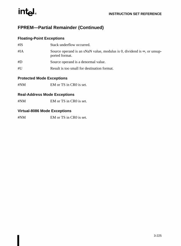
INSTRUCTION SET REFERENCE
FPREM—Partial Remainder (Continued)
Floating-Point Exceptions
#IS Stack underflow occurred.
#IA Source operand is an sNaN value, modulus is 0, dividend is ∞, or unsup-ported format.
#D Source operand is a denormal value.
#U Result is too small for destination format.
Protected Mode Exceptions
#NM EM or TS in CR0 is set.
Real-Address Mode Exceptions
#NM EM or TS in CR0 is set.
Virtual-8086 Mode Exceptions
#NM EM or TS in CR0 is set.
3-225

INSTRUCTION SET REFERENCE
FPREM1—Partial Remainder
Description
This instruction computes the IEEE remainder obtained from dividing the value in the ST(0)register (the dividend) by the value in the ST(1) register (the divisor or modulus), and stores theresult in ST(0). The remainder represents the following value:
Remainder = ST(0) − (Q ∗ ST(1))
Here, Q is an integer value that is obtained by rounding the real-number quotient of [ST(0) /ST(1)] toward the nearest integer value. The magnitude of the remainder is less than half themagnitude of the modulus, unless a partial remainder was computed (as described below).
This instruction produces an exact result; the precision (inexact) exception does not occur andthe rounding control has no effect. The following table shows the results obtained whencomputing the remainder of various classes of numbers, assuming that underflow does notoccur.
NOTES:
F Means finite-real number.
* Indicates floating-point invalid-arithmetic-operand (#IA) exception.
** Indicates floating-point zero-divide (#Z) exception.
When the result is 0, its sign is the same as that of the dividend. When the modulus is ∞, theresult is equal to the value in ST(0).
The FPREM1 instruction computes the remainder specified in IEEE Std 754. This instructionoperates differently from the FPREM instruction in the way that it rounds the quotient of ST(0)divided by ST(1) to an integer (refer to the “Operation” section below).
Opcode Instruction Description
D9 F5 FPREM1 Replace ST(0) with the IEEE remainder obtained from dividing ST(0) by ST(1)
ST(1)
−∞ −F −0 +0 +F +∞ NaN
−∞ * * * * * * NaN
ST(0) −F ST(0) ±F or −0 ** ** ±F or −0 ST(0) NaN
−0 −0 −0 * * −0 −0 NaN
+0 +0 +0 * * +0 +0 NaN
+F ST(0) ±F or +0 ** ** ±F or +0 ST(0) NaN
+∞ * * * * * * NaN
NaN NaN NaN NaN NaN NaN NaN NaN
3-226

INSTRUCTION SET REFERENCE
FPREM1—Partial Remainder (Continued)
Like the FPREM instruction, the FPREM1 computes the remainder through iterative subtrac-tion, but can reduce the exponent of ST(0) by no more than 63 in one execution of the instruc-tion. If the instruction succeeds in producing a remainder that is less than one half the modulus,the operation is complete and the C2 flag in the FPU status word is cleared. Otherwise, C2 isset, and the result in ST(0) is called the partial remainder. The exponent of the partialremainder will be less than the exponent of the original dividend by at least 32. Software can re-execute the instruction (using the partial remainder in ST(0) as the dividend) until C2 is cleared.(Note that while executing such a remainder-computation loop, a higher-priority interruptingroutine that needs the FPU can force a context switch in-between the instructions in the loop.)
An important use of the FPREM1 instruction is to reduce the arguments of periodic functions.When reduction is complete, the instruction stores the three least-significant bits of the quotientin the C3, C1, and C0 flags of the FPU status word. This information is important in argumentreduction for the tangent function (using a modulus of π/4), because it locates the original anglein the correct one of eight sectors of the unit circle.
Operation
D ← exponent(ST(0)) – exponent(ST(1));IF D < 64
THENQ ← Integer(RoundTowardNearestInteger(ST(0) / ST(1)));ST(0) ← ST(0) – (ST(1) ∗ Q);C2 ← 0;C0, C3, C1 ← LeastSignificantBits(Q); (* Q2, Q1, Q0 *)
ELSEC2 ← 1;N ← an implementation-dependent number between 32 and 63;QQ ← Integer(TruncateTowardZero((ST(0) / ST(1)) / 2(D − N)));ST(0) ← ST(0) – (ST(1) ∗ QQ ∗ 2(D − N));
FI;
FPU Flags Affected
C0 Set to bit 2 (Q2) of the quotient.
C1 Set to 0 if stack underflow occurred; otherwise, set to least significant bitof quotient (Q0).
C2 Set to 0 if reduction complete; set to 1 if incomplete.
C3 Set to bit 1 (Q1) of the quotient.
3-227

INSTRUCTION SET REFERENCE
FPREM1—Partial Remainder (Continued)
Floating-Point Exceptions
#IS Stack underflow occurred.
#IA Source operand is an sNaN value, modulus (divisor) is 0, dividend is ∞, orunsupported format.
#D Source operand is a denormal value.
#U Result is too small for destination format.
Protected Mode Exceptions
#NM EM or TS in CR0 is set.
Real-Address Mode Exceptions
#NM EM or TS in CR0 is set.
Virtual-8086 Mode Exceptions
#NM EM or TS in CR0 is set.
3-228

INSTRUCTION SET REFERENCE
edw does
d is set,ceptionut-of-e
FPTAN—Partial Tangent
Description
This instruction computes the tangent of the source operand in register ST(0), stores the resultin ST(0), and pushes a 1.0 onto the FPU register stack. The source operand must be given inradians and must be less than ±263. The following table shows the unmasked results obtainwhen computing the partial tangent of various classes of numbers, assuming that underflonot occur.
NOTES:
F Means finite-real number.
* Indicates floating-point invalid-arithmetic-operand (#IA) exception.
If the source operand is outside the acceptable range, the C2 flag in the FPU status worand the value in register ST(0) remains unchanged. The instruction does not raise an exwhen the source operand is out of range. It is up to the program to check the C2 flag for orange conditions. Source values outside the range −263 to +263 can be reduced to the range of thinstruction by subtracting an appropriate integer multiple of 2π or by using the FPREM instruc-tion with a divisor of 2π. Refer to Section 7.5.8., Pi in Chapter 7, Floating-Point Unit of the IntelArchitecture Software Developer’s Manual, Volume 1, for a discussion of the proper value to usefor π in performing such reductions.
The value 1.0 is pushed onto the register stack after the tangent has been computed to maintaincompatibility with the Intel 8087 and Intel287 math coprocessors. This operation also simplifiesthe calculation of other trigonometric functions. For instance, the cotangent (which is the recip-rocal of the tangent) can be computed by executing a FDIVR instruction after the FPTANinstruction.
Opcode Instruction Clocks Description
D9 F2 FPTAN 17-173 Replace ST(0) with its tangent and push 1 onto the FPU stack.
ST(0) SRC ST(0) DEST
−∞ *
−F −F to +F
−0 −0
+0 +0
+F −F to +F
+∞ *
NaN NaN
3-229

INSTRUCTION SET REFERENCE
FPTAN—Partial Tangent (Continued)
Operation
IF ST(0) < 263
THENC2 ← 0;ST(0) ← tan(ST(0));TOP ← TOP − 1;ST(0) ← 1.0;
ELSE (*source operand is out-of-range *)C2 ← 1;
FI;
FPU Flags Affected
C1 Set to 0 if stack underflow occurred; set to 1 if stack overflow occurred.
Indicates rounding direction if the inexact-result exception (#P) is gener-ated: 0 = not roundup; 1 = roundup.
C2 Set to 1 if source operand is outside the range −263 to +263; otherwise,cleared to 0.
C0, C3 Undefined.
Floating-Point Exceptions
#IS Stack underflow occurred.
#IA Source operand is an sNaN value, ∞, or unsupported format.
#D Source operand is a denormal value.
#U Result is too small for destination format.
#P Value cannot be represented exactly in destination format.
Protected Mode Exceptions
#NM EM or TS in CR0 is set.
Real-Address Mode Exceptions
#NM EM or TS in CR0 is set.
Virtual-8086 Mode Exceptions
#NM EM or TS in CR0 is set.
3-230

INSTRUCTION SET REFERENCE
FRNDINT—Round to Integer
Description
This instruction rounds the source value in the ST(0) register to the nearest integral value,depending on the current rounding mode (setting of the RC field of the FPU control word), andstores the result in ST(0).
If the source value is ∞, the value is not changed. If the source value is not an integral value, thefloating-point inexact-result exception (#P) is generated.
Operation
ST(0) ← RoundToIntegralValue(ST(0));
FPU Flags Affected
C1 Set to 0 if stack underflow occurred.
Indicates rounding direction if the inexact-result exception (#P) is gener-ated: 0 = not roundup; 1 = roundup.
C0, C2, C3 Undefined.
Floating-Point Exceptions
#IS Stack underflow occurred.
#IA Source operand is an sNaN value or unsupported format.
#D Source operand is a denormal value.
#P Source operand is not an integral value.
Protected Mode Exceptions
#NM EM or TS in CR0 is set.
Real-Address Mode Exceptions
#NM EM or TS in CR0 is set.
Virtual-8086 Mode Exceptions
#NM EM or TS in CR0 is set.
Opcode Instruction Description
D9 FC FRNDINT Round ST(0) to an integer.
3-231

INSTRUCTION SET REFERENCE
FRSTOR—Restore FPU State
Description
This instruction loads the FPU state (operating environment and register stack) from thememory area specified with the source operand. This state data is typically written to the spec-ified memory location by a previous FSAVE/FNSAVE instruction.
The FPU operating environment consists of the FPU control word, status word, tag word,instruction pointer, data pointer, and last opcode. Figures 7-13 through Figure 7-16 in Chapter7, Floating-Point Unit of the Intel Architecture Software Developer’s Manual, Volume 1, showthe layout in memory of the stored environment, depending on the operating mode of theprocessor (protected or real) and the current operand-size attribute (16-bit or 32-bit). In virtual-8086 mode, the real mode layouts are used. The contents of the FPU register stack are stored inthe 80 bytes immediately follow the operating environment image.
The FRSTOR instruction should be executed in the same operating mode as the correspondingFSAVE/FNSAVE instruction.
Intel Architecture Compatibility
On a Pentium® III processor, the FRSTOR instruction operates the same as on a Pentium® IIprocessor. It has no effect on the SIMD floating-point functional unit or control/status register,i.e., it does not restore the SIMD floating-point processor state.
Operation
FPUControlWord ← SRC(FPUControlWord);FPUStatusWord ← SRC(FPUStatusWord);FPUTagWord ← SRC(FPUTagWord);FPUDataPointer ← SRC(FPUDataPointer);FPUInstructionPointer ← SRC(FPUInstructionPointer);FPULastInstructionOpcode ← SRC(FPULastInstructionOpcode);ST(0) ← SRC(ST(0));ST(1) ← SRC(ST(1));ST(2) ← SRC(ST(2));ST(3) ← SRC(ST(3));ST(4) ← SRC(ST(4));ST(5) ← SRC(ST(5));ST(6) ← SRC(ST(6));ST(7) ← SRC(ST(7));
Opcode Instruction Description
DD /4 FRSTOR m94/108byte Load FPU state from m94byte or m108byte.
3-232

INSTRUCTION SET REFERENCE
FRSTOR—Restore FPU State (Continued)
FPU Flags Affected
The C0, C1, C2, C3 flags are loaded.
Floating-Point Exceptions
None; however, this operation might unmask an existing exception that has been detected butnot generated, because it was masked. Here, the exception is generated at the completion of theinstruction.
Protected Mode Exceptions
#GP(0) If a memory operand effective address is outside the CS, DS, ES, FS, orGS segment limit.
If the DS, ES, FS, or GS register is used to access memory and it containsa null segment selector.
#SS(0) If a memory operand effective address is outside the SS segment limit.
#NM EM or TS in CR0 is set.
#PF(fault-code) If a page fault occurs.
#AC(0) If alignment checking is enabled and an unaligned memory reference ismade while the current privilege level is 3.
Real-Address Mode Exceptions
#GP If a memory operand effective address is outside the CS, DS, ES, FS, orGS segment limit.
#SS If a memory operand effective address is outside the SS segment limit.
#NM EM or TS in CR0 is set.
3-233

INSTRUCTION SET REFERENCE
FRSTOR—Restore FPU State (Continued)
Virtual-8086 Mode Exceptions
#GP(0) If a memory operand effective address is outside the CS, DS, ES, FS, orGS segment limit.
#SS(0) If a memory operand effective address is outside the SS segment limit.
#NM EM or TS in CR0 is set.
#PF(fault-code) If a page fault occurs.
#AC(0) If alignment checking is enabled and an unaligned memory reference ismade.
Comments
This instruction has no effect on the state of SIMD floating-point registers.
3-234

INSTRUCTION SET REFERENCE
ds toogram
FSAVE/FNSAVE—Store FPU State
NOTE:
* Refer to “Intel Architecture Compatibility” below.
Description
These instructions store the current FPU state (operating environment and register stack) at thespecified destination in memory, and then re-initializes the FPU. The FSAVE instruction checksfor and handles pending unmasked floating-point exceptions before storing the FPU state; theFNSAVE instruction does not.
The FPU operating environment consists of the FPU control word, status word, tag word,instruction pointer, data pointer, and last opcode. Figures 7-13 through Figures 7-16 in Chapter7, Floating-Point Unit of the Intel Architecture Software Developer’s Manual, Volume 1 showthe layout in memory of the stored environment, depending on the operating mode of theprocessor (protected or real) and the current operand-size attribute (16-bit or 32-bit). In virtual-8086 mode, the real mode layouts are used. The contents of the FPU register stack are stored inthe 80 bytes immediately follow the operating environment image.
The saved image reflects the state of the FPU after all floating-point instructions preceding theFSAVE/FNSAVE instruction in the instruction stream have been executed.
After the FPU state has been saved, the FPU is reset to the same default values it is set to withthe FINIT/FNINIT instructions (refer to “FINIT/FNINIT—Initialize Floating-Point Unit” inthis chapter).
The FSAVE/FNSAVE instructions are typically used when the operating system neeperform a context switch, an exception handler needs to use the FPU, or an application prneeds to pass a “clean” FPU to a procedure.
Intel Architecture Compatibility
For Intel math coprocessors and FPUs prior to the Intel Pentium® processor, an FWAIT instruc-tion should be executed before attempting to read from the memory image stored with a priorFSAVE/FNSAVE instruction. This FWAIT instruction helps insure that the storage operationhas been completed.
On a Pentium® III processor, the FSAVE/FNSAVE instructions operate the same as on aPentium® II processor. They have no effect on the Pentium® III processor SIMD floating-pointfunctional unit or control/status register, i.e., they do not save the SIMD floating-point processorstate.
Opcode Instruction Description
9B DD /6 FSAVE m94/108byte Store FPU state to m94byte or m108byte after checking for pending unmasked floating-point exceptions. Then re-initialize the FPU.
DD /6 FNSAVE* m94/108byte Store FPU environment to m94byte or m108byte without checking for pending unmasked floating-point exceptions. Then re-initialize the FPU.
3-235
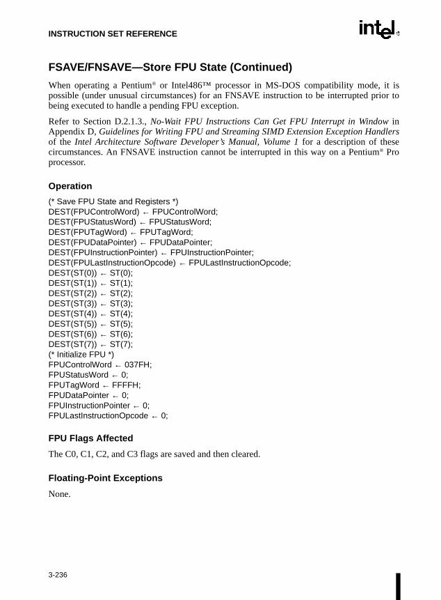
INSTRUCTION SET REFERENCE
isior to
FSAVE/FNSAVE—Store FPU State (Continued)
When operating a Pentium® or Intel486™ processor in MS-DOS compatibility mode, it possible (under unusual circumstances) for an FNSAVE instruction to be interrupted prbeing executed to handle a pending FPU exception.
Refer to Section D.2.1.3., No-Wait FPU Instructions Can Get FPU Interrupt in Window inAppendix D, Guidelines for Writing FPU and Streaming SIMD Extension Exception Handlersof the Intel Architecture Software Developer’s Manual, Volume 1 for a description of thesecircumstances. An FNSAVE instruction cannot be interrupted in this way on a Pentium® Proprocessor.
Operation
(* Save FPU State and Registers *)DEST(FPUControlWord) ← FPUControlWord;DEST(FPUStatusWord) ← FPUStatusWord;DEST(FPUTagWord) ← FPUTagWord;DEST(FPUDataPointer) ← FPUDataPointer;DEST(FPUInstructionPointer) ← FPUInstructionPointer;DEST(FPULastInstructionOpcode) ← FPULastInstructionOpcode;DEST(ST(0)) ← ST(0);DEST(ST(1)) ← ST(1);DEST(ST(2)) ← ST(2);DEST(ST(3)) ← ST(3);DEST(ST(4)) ← ST(4);DEST(ST(5)) ← ST(5);DEST(ST(6)) ← ST(6);DEST(ST(7)) ← ST(7);(* Initialize FPU *)FPUControlWord ← 037FH;FPUStatusWord ← 0;FPUTagWord ← FFFFH;FPUDataPointer ← 0;FPUInstructionPointer ← 0;FPULastInstructionOpcode ← 0;
FPU Flags Affected
The C0, C1, C2, and C3 flags are saved and then cleared.
Floating-Point Exceptions
None.
3-236

INSTRUCTION SET REFERENCE
FSAVE/FNSAVE—Store FPU State (Continued)
Protected Mode Exceptions
#GP(0) If destination is located in a nonwritable segment.
If a memory operand effective address is outside the CS, DS, ES, FS, orGS segment limit.
If the DS, ES, FS, or GS register is used to access memory and it containsa null segment selector.
#SS(0) If a memory operand effective address is outside the SS segment limit.
#NM EM or TS in CR0 is set.
#PF(fault-code) If a page fault occurs.
#AC(0) If alignment checking is enabled and an unaligned memory reference ismade while the current privilege level is 3.
Real-Address Mode Exceptions
#GP If a memory operand effective address is outside the CS, DS, ES, FS, orGS segment limit.
#SS If a memory operand effective address is outside the SS segment limit.
#NM EM or TS in CR0 is set.
Virtual-8086 Mode Exceptions
#GP(0) If a memory operand effective address is outside the CS, DS, ES, FS, orGS segment limit.
#SS(0) If a memory operand effective address is outside the SS segment limit.
#NM EM or TS in CR0 is set.
#PF(fault-code) If a page fault occurs.
#AC(0) If alignment checking is enabled and an unaligned memory reference ismade.
Comments
This instruction has no effect on the state of SIMD floating-point registers.
3-237

INSTRUCTION SET REFERENCE
a.
n, as
FSCALE—Scale
Description
This instruction multiplies the destination operand by 2 to the power of the source operand andstores the result in the destination operand. The destination operand is a real value that is locatedin register ST(0). The source operand is the nearest integer value that is smaller than the valuein the ST(1) register (that is, the value in register ST(1) is truncated toward 0 to its nearestinteger value to form the source operand). This instruction provides rapid multiplication or divi-sion by integral powers of 2 because it is implemented by simply adding an integer value (thesource operand) to the exponent of the value in register ST(0). The following table shows theresults obtained when scaling various classes of numbers, assuming that neither overflow norunderflow occurs.
NOTES:
F Means finite-real number.
N Means integer.
In most cases, only the exponent is changed and the mantissa (significand) remains unchanged.However, when the value being scaled in ST(0) is a denormal value, the mantissa is also changedand the result may turn out to be a normalized number. Similarly, if overflow or underflowresults from a scale operation, the resulting mantissa will differ from the source’s mantiss
The FSCALE instruction can also be used to reverse the action of the FXTRACT instructioshown in the following example:
FXTRACT;FSCALE;FSTP ST(1);
Opcode Instruction Description
D9 FD FSCALE Scale ST(0) by ST(1).
ST(1)
−N 0 +N
−∞ −∞ −∞ −∞
ST(0) −F −F −F −F
−0 −0 −0 −0
+0 +0 +0 +0
+F +F +F +F
+∞ +∞ +∞ +∞
NaN NaN NaN NaN
3-238

INSTRUCTION SET REFERENCE
FSCALE—Scale (Continued)
In this example, the FXTRACT instruction extracts the significand and exponent from the valuein ST(0) and stores them in ST(0) and ST(1) respectively. The FSCALE then scales the signifi-cand in ST(0) by the exponent in ST(1), recreating the original value before the FXTRACToperation was performed. The FSTP ST(1) instruction overwrites the exponent (extracted by theFXTRACT instruction) with the recreated value, which returns the stack to its original state withonly one register [ST(0)] occupied.
Operation
ST(0) ← ST(0) ∗ 2ST(1);
FPU Flags Affected
C1 Set to 0 if stack underflow occurred.
Indicates rounding direction if the inexact-result exception (#P) is gener-ated: 0 = not roundup; 1 = roundup.
C0, C2, C3 Undefined.
Floating-Point Exceptions
#IS Stack underflow occurred.
#IA Source operand is an sNaN value or unsupported format.
#D Source operand is a denormal value.
#U Result is too small for destination format.
#O Result is too large for destination format.
#P Value cannot be represented exactly in destination format.
Protected Mode Exceptions
#NM EM or TS in CR0 is set.
Real-Address Mode Exceptions
#NM EM or TS in CR0 is set.
Virtual-8086 Mode Exceptions
#NM EM or TS in CR0 is set.
3-239

INSTRUCTION SET REFERENCE
FSIN—Sine
Description
This instruction calculates the sine of the source operand in register ST(0) and stores the resultin ST(0). The source operand must be given in radians and must be within the range −263 to +263.The following table shows the results obtained when taking the sine of various classes ofnumbers, assuming that underflow does not occur.
NOTES:
F Means finite-real number.
* Indicates floating-point invalid-arithmetic-operand (#IA) exception.
If the source operand is outside the acceptable range, the C2 flag in the FPU status word is set,and the value in register ST(0) remains unchanged. The instruction does not raise an exceptionwhen the source operand is out of range. It is up to the program to check the C2 flag for out-of-range conditions. Source values outside the range −263 to +263 can be reduced to the range of theinstruction by subtracting an appropriate integer multiple of 2π or by using the FPREM instruc-tion with a divisor of 2π. Refer to Section 7.5.8., Pi in Chapter 7, Floating-Point Unit of the IntelArchitecture Software Developer’s Manual, Volume 1, for a discussion of the proper value to usefor π in performing such reductions.
Operation
IF ST(0) < 263
THENC2 ← 0;ST(0) ← sin(ST(0));
ELSE (* source operand out of range *)C2 ← 1;
FI:
Opcode Instruction Description
D9 FE FSIN Replace ST(0) with its sine.
SRC (ST(0)) DEST (ST(0))
−∞ *
−F −1 to +1
−0 −0
+0 +0
+F −1 to +1
+∞ *
NaN NaN
3-240

INSTRUCTION SET REFERENCE
FSIN—Sine (Continued)
FPU Flags Affected
C1 Set to 0 if stack underflow occurred.
Indicates rounding direction if the inexact-result exception (#P) is gener-ated: 0 = not roundup; 1 = roundup.
C2 Set to 1 if source operand is outside the range −263 to +263; otherwise,cleared to 0.
C0, C3 Undefined.
Floating-Point Exceptions
#IS Stack underflow occurred.
#IA Source operand is an sNaN value, ∞, or unsupported format.
#D Source operand is a denormal value.
#P Value cannot be represented exactly in destination format.
Protected Mode Exceptions
#NM EM or TS in CR0 is set.
Real-Address Mode Exceptions
#NM EM or TS in CR0 is set.
Virtual-8086 Mode Exceptions
#NM EM or TS in CR0 is set.
3-241

INSTRUCTION SET REFERENCE
FSINCOS—Sine and Cosine
Description
This instruction computes both the sine and the cosine of the source operand in register ST(0),stores the sine in ST(0), and pushes the cosine onto the top of the FPU register stack. (Thisinstruction is faster than executing the FSIN and FCOS instructions in succession.)
The source operand must be given in radians and must be within the range −263 to +263. Thefollowing table shows the results obtained when taking the sine and cosine of various classes ofnumbers, assuming that underflow does not occur.
NOTES:
F Means finite-real number.
* Indicates floating-point invalid-arithmetic-operand (#IA) exception.
If the source operand is outside the acceptable range, the C2 flag in the FPU status word is set,and the value in register ST(0) remains unchanged. The instruction does not raise an exceptionwhen the source operand is out of range. It is up to the program to check the C2 flag for out-of-range conditions. Source values outside the range −263 to +263 can be reduced to the range of theinstruction by subtracting an appropriate integer multiple of 2π or by using the FPREM instruc-tion with a divisor of 2π. Refer to Section 7.5.8., Pi in Chapter 7.5.8., Pi of the Intel ArchitectureSoftware Developer’s Manual, Volume 1, for a discussion of the proper value to use for π inperforming such reductions.
Opcode Instruction Description
D9 FB FSINCOS Compute the sine and cosine of ST(0); replace ST(0) with the sine, and push the cosine onto the register stack.
SRC DEST
ST(0) ST(1) Cosine ST(0) Sine
−∞ * *
−F −1 to +1 −1 to +1
−0 +1 −0
+0 +1 +0
+F −1 to +1 −1 to +1
+∞ * *
NaN NaN NaN
3-242

INSTRUCTION SET REFERENCE
FSINCOS—Sine and Cosine (Continued)
Operation
IF ST(0) < 263
THENC2 ← 0;TEMP ← cosine(ST(0));ST(0) ← sine(ST(0));
TOP ← TOP − 1;ST(0) ← TEMP;
ELSE (* source operand out of range *)C2 ← 1;
FI:
FPU Flags Affected
C1 Set to 0 if stack underflow occurred; set to 1 of stack overflow occurs.
Indicates rounding direction if the exception (#P) is generated: 0 = notroundup; 1 = roundup.
C2 Set to 1 if source operand is outside the range −263 to +263; otherwise,cleared to 0.
C0, C3 Undefined.
Floating-Point Exceptions
#IS Stack underflow occurred.
#IA Source operand is an sNaN value, ∞, or unsupported format.
#D Source operand is a denormal value.
#U Result is too small for destination format.
#P Value cannot be represented exactly in destination format.
Protected Mode Exceptions
#NM EM or TS in CR0 is set.
Real-Address Mode Exceptions
#NM EM or TS in CR0 is set.
Virtual-8086 Mode Exceptions
#NM EM or TS in CR0 is set.
3-243

INSTRUCTION SET REFERENCE
FSQRT—Square Root
Description
This instruction calculates the square root of the source value in the ST(0) register and stores theresult in ST(0).
The following table shows the results obtained when taking the square root of various classes ofnumbers, assuming that neither overflow nor underflow occurs.
NOTES:
F Means finite-real number.
* Indicates floating-point invalid-arithmetic-operand (#IA) exception.
Operation
ST(0) ← SquareRoot(ST(0));
FPU Flags Affected
C1 Set to 0 if stack underflow occurred.
Indicates rounding direction if inexact-result exception (#P) is generated:0 = not roundup; 1 = roundup.
C0, C2, C3 Undefined.
Opcode Instruction Description
D9 FA FSQRT Calculates square root of ST(0) and stores the result in ST(0)
SRC (ST(0)) DEST (ST(0))
−∞ *
−F *
−0 −0
+0 +0
+F +F
+∞ +∞
NaN NaN
3-244

INSTRUCTION SET REFERENCE
FSQRT—Square Root (Continued)
Floating-Point Exceptions
#IS Stack underflow occurred.
#IA Source operand is an sNaN value or unsupported format.
Source operand is a negative value (except for −0).
#D Source operand is a denormal value.
#P Value cannot be represented exactly in destination format.
Protected Mode Exceptions
#NM EM or TS in CR0 is set.
Real-Address Mode Exceptions
#NM EM or TS in CR0 is set.
Virtual-8086 Mode Exceptions
#NM EM or TS in CR0 is set.
3-245

INSTRUCTION SET REFERENCE
heentity
s not
FST/FSTP—Store Real
Description
The FST instruction copies the value in the ST(0) register to the destination operand, which canbe a memory location or another register in the FPU register stack. When storing the value inmemory, the value is converted to single- or double-real format.
The FSTP instruction performs the same operation as the FST instruction and then pops theregister stack. To pop the register stack, the processor marks the ST(0) register as empty andincrements the stack pointer (TOP) by 1. The FSTP instruction can also store values in memoryin extended-real format.
If the destination operand is a memory location, the operand specifies the address where the firstbyte of the destination value is to be stored. If the destination operand is a register, the operandspecifies a register in the register stack relative to the top of the stack.
If the destination size is single- or double-real, the significand of the value being stored isrounded to the width of the destination (according to rounding mode specified by the RC fieldof the FPU control word), and the exponent is converted to the width and bias of the destinationformat. If the value being stored is too large for the destination format, a numeric overflowexception (#O) is generated and, if the exception is unmasked, no value is stored in the destina-tion operand. If the value being stored is a denormal value, the denormal exception (#D) is notgenerated. This condition is simply signalled as a numeric underflow exception (#U) condition.
If the value being stored is ±0, ±∞, or a NaN, the least-significant bits of the significand and texponent are truncated to fit the destination format. This operation preserves the value’s idas a 0, ∞, or NaN.
If the destination operand is a non-empty register, the invalid-operation exception igenerated.
Operation
DEST ← ST(0);IF instruction = FSTP
THEN PopRegisterStack;
FI;
Opcode Instruction Description
D9 /2 FST m32real Copy ST(0) to m32real
DD /2 FST m64real Copy ST(0) to m64real
DD D0+i FST ST(i) Copy ST(0) to ST(i)
D9 /3 FSTP m32real Copy ST(0) to m32real and pop register stack
DD /3 FSTP m64real Copy ST(0) to m64real and pop register stack
DB /7 FSTP m80real Copy ST(0) to m80real and pop register stack
DD D8+i FSTP ST(i) Copy ST(0) to ST(i) and pop register stack
3-246
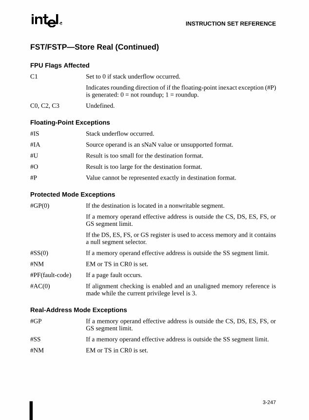
INSTRUCTION SET REFERENCE
FST/FSTP—Store Real (Continued)
FPU Flags Affected
C1 Set to 0 if stack underflow occurred.
Indicates rounding direction of if the floating-point inexact exception (#P)is generated: 0 = not roundup; 1 = roundup.
C0, C2, C3 Undefined.
Floating-Point Exceptions
#IS Stack underflow occurred.
#IA Source operand is an sNaN value or unsupported format.
#U Result is too small for the destination format.
#O Result is too large for the destination format.
#P Value cannot be represented exactly in destination format.
Protected Mode Exceptions
#GP(0) If the destination is located in a nonwritable segment.
If a memory operand effective address is outside the CS, DS, ES, FS, orGS segment limit.
If the DS, ES, FS, or GS register is used to access memory and it containsa null segment selector.
#SS(0) If a memory operand effective address is outside the SS segment limit.
#NM EM or TS in CR0 is set.
#PF(fault-code) If a page fault occurs.
#AC(0) If alignment checking is enabled and an unaligned memory reference ismade while the current privilege level is 3.
Real-Address Mode Exceptions
#GP If a memory operand effective address is outside the CS, DS, ES, FS, orGS segment limit.
#SS If a memory operand effective address is outside the SS segment limit.
#NM EM or TS in CR0 is set.
3-247

INSTRUCTION SET REFERENCE
FST/FSTP—Store Real (Continued)
Virtual-8086 Mode Exceptions
#GP(0) If a memory operand effective address is outside the CS, DS, ES, FS, orGS segment limit.
#SS(0) If a memory operand effective address is outside the SS segment limit.
#NM EM or TS in CR0 is set.
#PF(fault-code) If a page fault occurs.
#AC(0) If alignment checking is enabled and an unaligned memory reference ismade.
3-248

INSTRUCTION SET REFERENCE
isior to
FSTCW/FNSTCW—Store Control Word
NOTE:
* Refer to “Intel Architecture Compatibility” below.
Description
These instructions store the current value of the FPU control word at the specified destinationin memory. The FSTCW instruction checks for and handles pending unmasked floating-pointexceptions before storing the control word; the FNSTCW instruction does not.
Intel Architecture Compatibility
When operating a Pentium® or Intel486™ processor in MS-DOS compatibility mode, it possible (under unusual circumstances) for an FNSTCW instruction to be interrupted prbeing executed to handle a pending FPU exception. Refer to Section D.2.1.3., No-Wait FPUInstructions Can Get FPU Interrupt in Window in Appendix D, Guidelines for Writing FPU andStreaming SIMD Extension Exception Handlers of the Intel Architecture Software Developer’sManual, Volume 1, for a description of these circumstances. An FNSTCW instruction cannot beinterrupted in this way on a Pentium® Pro processor.
On a Pentium® III processor, the FSTCW/FNSTCW instructions operate the same as on aPentium® II processor. They have no effect on the Pentium® III processor SIMD floating-pointfunctional unit or control/status register.
Operation
DEST ← FPUControlWord;
FPU Flags Affected
The C0, C1, C2, and C3 flags are undefined.
Floating-Point Exceptions
None.
Opcode Instruction Description
9B D9 /7 FSTCW m2byte Store FPU control word to m2byte after checking for pending unmasked floating-point exceptions.
D9 /7 FNSTCW* m2byte Store FPU control word to m2byte without checking for pending unmasked floating-point exceptions.
3-249

INSTRUCTION SET REFERENCE
FSTCW/FNSTCW—Store Control Word (Continued)
Protected Mode Exceptions
#GP(0) If the destination is located in a nonwritable segment.
If a memory operand effective address is outside the CS, DS, ES, FS, orGS segment limit.
If the DS, ES, FS, or GS register is used to access memory and it containsa null segment selector.
#SS(0) If a memory operand effective address is outside the SS segment limit.
#NM EM or TS in CR0 is set.
#PF(fault-code) If a page fault occurs.
#AC(0) If alignment checking is enabled and an unaligned memory reference ismade while the current privilege level is 3.
Real-Address Mode Exceptions
#GP If a memory operand effective address is outside the CS, DS, ES, FS, orGS segment limit.
#SS If a memory operand effective address is outside the SS segment limit.
#NM EM or TS in CR0 is set.
Virtual-8086 Mode Exceptions
#GP(0) If a memory operand effective address is outside the CS, DS, ES, FS, orGS segment limit.
#SS(0) If a memory operand effective address is outside the SS segment limit.
#NM EM or TS in CR0 is set.
#PF(fault-code) If a page fault occurs.
#AC(0) If alignment checking is enabled and an unaligned memory reference ismade.
3-250

INSTRUCTION SET REFERENCE
isior to
FSTENV/FNSTENV—Store FPU Environment
NOTE:
* Refer to “Intel Architecture Compatibility” below.
Description
These instructions save the current FPU operating environment at the memory location specifiedwith the destination operand, and then masks all floating-point exceptions. The FPU operatingenvironment consists of the FPU control word, status word, tag word, instruction pointer, datapointer, and last opcode. Figures 7-13 through Figure 7-16 in Chapter 7, Floating-Point Unit ofthe Intel Architecture Software Developer’s Manual, Volume 1 show the layout in memory of thestored environment, depending on the operating mode of the processor (protected or real) andthe current operand-size attribute (16-bit or 32-bit). In virtual-8086 mode, the real mode layoutsare used.
The FSTENV instruction checks for and handles any pending unmasked floating-point excep-tions before storing the FPU environment; the FNSTENV instruction does not.The savedimage reflects the state of the FPU after all floating-point instructions preceding theFSTENV/FNSTENV instruction in the instruction stream have been executed.
These instructions are often used by exception handlers because they provide access to the FPUinstruction and data pointers. The environment is typically saved in the stack. Masking allexceptions after saving the environment prevents floating-point exceptions from interrupting theexception handler.
Intel Architecture Compatibility
When operating a Pentium® or Intel486™ processor in MS-DOS compatibility mode, it possible (under unusual circumstances) for an FNSTENV instruction to be interrupted prbeing executed to handle a pending FPU exception. Refer to Section D.2.1.3., No-Wait FPUInstructions Can Get FPU Interrupt in Window in Appendix D, Guidelines for Writing FPU andStreaming SIMD Extension Exception Handlers of the Intel Architecture Software Developer’sManual, Volume 1, for a description of these circumstances. An FNSTENV instruction cannotbe interrupted in this way on a Pentium® Pro processor.
On a Pentium® III processor, the FSTENV/FNSTENV instructions operate the same as on aPentium® II processor. They have no effect on the Pentium® III processor SIMD floating-pointfunctional unit or control/status register.
Opcode Instruction Description
9B D9 /6 FSTENV m14/28byte Store FPU environment to m14byte or m28byte after checking for pending unmasked floating-point exceptions. Then mask all floating-point exceptions.
D9 /6 FNSTENV* m14/28byte Store FPU environment to m14byte or m28byte without checking for pending unmasked floating-point exceptions. Then mask all floating-point exceptions.
3-251

INSTRUCTION SET REFERENCE
FSTENV/FNSTENV—Store FPU Environment (Continued)
Operation
DEST(FPUControlWord) ← FPUControlWord;DEST(FPUStatusWord) ← FPUStatusWord;DEST(FPUTagWord) ← FPUTagWord;DEST(FPUDataPointer) ← FPUDataPointer;DEST(FPUInstructionPointer) ← FPUInstructionPointer;DEST(FPULastInstructionOpcode) ← FPULastInstructionOpcode;
FPU Flags Affected
The C0, C1, C2, and C3 are undefined.
Floating-Point Exceptions
None.
Protected Mode Exceptions
#GP(0) If the destination is located in a nonwritable segment.
If a memory operand effective address is outside the CS, DS, ES, FS, orGS segment limit.
If the DS, ES, FS, or GS register is used to access memory and it containsa null segment selector.
#SS(0) If a memory operand effective address is outside the SS segment limit.
#NM EM or TS in CR0 is set.
#PF(fault-code) If a page fault occurs.
#AC(0) If alignment checking is enabled and an unaligned memory reference ismade while the current privilege level is 3.
Real-Address Mode Exceptions
#GP If a memory operand effective address is outside the CS, DS, ES, FS, orGS segment limit.
#SS If a memory operand effective address is outside the SS segment limit.
#NM EM or TS in CR0 is set.
3-252

INSTRUCTION SET REFERENCE
FSTENV/FNSTENV—Store FPU Environment (Continued)
Virtual-8086 Mode Exceptions
#GP(0) If a memory operand effective address is outside the CS, DS, ES, FS, orGS segment limit.
#SS(0) If a memory operand effective address is outside the SS segment limit.
#NM EM or TS in CR0 is set.
#PF(fault-code) If a page fault occurs.
#AC(0) If alignment checking is enabled and an unaligned memory reference ismade.
3-253

INSTRUCTION SET REFERENCE
isior to
FSTSW/FNSTSW—Store Status Word
NOTE:
* Refer to “Intel Architecture Compatibility” below.
Description
These instructions store the current value of the FPU status word in the destination location. Thedestination operand can be either a two-byte memory location or the AX register. The FSTSWinstruction checks for and handles pending unmasked floating-point exceptions before storingthe status word; the FNSTSW instruction does not.
The FNSTSW AX form of the instruction is used primarily in conditional branching (forinstance, after an FPU comparison instruction or an FPREM, FPREM1, or FXAM instruction),where the direction of the branch depends on the state of the FPU condition code flags. Refer toSection 7.3.3., Branching and Conditional Moves on FPU Condition Codes in Chapter 7,Floating-Point Unit of the Intel Architecture Software Developer’s Manual, Volume 1. Thisinstruction can also be used to invoke exception handlers (by examining the exception flags) inenvironments that do not use interrupts. When the FNSTSW AX instruction is executed, the AXregister is updated before the processor executes any further instructions. The status stored inthe AX register is thus guaranteed to be from the completion of the prior FPU instruction.
Intel Architecture Compatibility
When operating a Pentium® or Intel486™ processor in MS-DOS compatibility mode, it possible (under unusual circumstances) for an FNSTSW instruction to be interrupted prbeing executed to handle a pending FPU exception. Refer to Section D.2.1.3., No-Wait FPUInstructions Can Get FPU Interrupt in Window in Appendix D, Guidelines for Writing FPU andStreaming SIMD Extension Exception Handlers of the Intel Architecture Software Developer’sManual, Volume 1, for a description of these circumstances. An FNSTSW instruction cannot beinterrupted in this way on a Pentium® Pro processor.
On a Pentium® III processor, the FSTSW/FNSTSW instructions operate the same as on aPentium® II processor. They have no effect on the Pentium® III processor SIMD floating-pointfunctional unit or control/status register.
Opcode Instruction Description
9B DD /7 FSTSW m2byte Store FPU status word at m2byte after checking for pending unmasked floating-point exceptions.
9B DF E0 FSTSW AX Store FPU status word in AX register after checking for pending unmasked floating-point exceptions.
DD /7 FNSTSW* m2byte Store FPU status word at m2byte without checking for pending unmasked floating-point exceptions.
DF E0 FNSTSW* AX Store FPU status word in AX register without checking for pending unmasked floating-point exceptions.
3-254

INSTRUCTION SET REFERENCE
FSTSW/FNSTSW—Store Status Word (Continued)
Operation
DEST ← FPUStatusWord;
FPU Flags Affected
The C0, C1, C2, and C3 are undefined.
Floating-Point Exceptions
None.
Protected Mode Exceptions
#GP(0) If the destination is located in a nonwritable segment.
If a memory operand effective address is outside the CS, DS, ES, FS, orGS segment limit.
If the DS, ES, FS, or GS register is used to access memory and it containsa null segment selector.
#SS(0) If a memory operand effective address is outside the SS segment limit.
#NM EM or TS in CR0 is set.
#PF(fault-code) If a page fault occurs.
#AC(0) If alignment checking is enabled and an unaligned memory reference ismade while the current privilege level is 3.
Real-Address Mode Exceptions
#GP If a memory operand effective address is outside the CS, DS, ES, FS, orGS segment limit.
#SS If a memory operand effective address is outside the SS segment limit.
#NM EM or TS in CR0 is set.
3-255

INSTRUCTION SET REFERENCE
FSTSW/FNSTSW—Store Status Word (Continued)
Virtual-8086 Mode Exceptions
#GP(0) If a memory operand effective address is outside the CS, DS, ES, FS, orGS segment limit.
#SS(0) If a memory operand effective address is outside the SS segment limit.
#NM EM or TS in CR0 is set.
#PF(fault-code) If a page fault occurs.
#AC(0) If alignment checking is enabled and an unaligned memory reference ismade.
3-256

INSTRUCTION SET REFERENCE
FSUB/FSUBP/FISUB—Subtract
Description
These instructions subtract the source operand from the destination operand and stores thedifference in the destination location. The destination operand is always an FPU data register;the source operand can be a register or a memory location. Source operands in memory can bein single-real, double-real, word-integer, or short-integer formats.
The no-operand version of the instruction subtracts the contents of the ST(0) register from theST(1) register and stores the result in ST(1). The one-operand version subtracts the contents ofa memory location (either a real or an integer value) from the contents of the ST(0) register andstores the result in ST(0). The two-operand version, subtracts the contents of the ST(0) registerfrom the ST(i) register or vice versa.
The FSUBP instructions perform the additional operation of popping the FPU register stackfollowing the subtraction. To pop the register stack, the processor marks the ST(0) register asempty and increments the stack pointer (TOP) by 1. The no-operand version of the floating-point subtract instructions always results in the register stack being popped. In some assemblers,the mnemonic for this instruction is FSUB rather than FSUBP.
The FISUB instructions convert an integer source operand to extended-real format beforeperforming the subtraction.
The following table shows the results obtained when subtracting various classes of numbersfrom one another, assuming that neither overflow nor underflow occurs. Here, the SRC value issubtracted from the DEST value (DEST − SRC = result).
When the difference between two operands of like sign is 0, the result is +0, except for the roundtoward −∞ mode, in which case the result is −0. This instruction also guarantees that +0 − (−0)= +0, and that −0 − (+0) = −0. When the source operand is an integer 0, it is treated as a +0.
When one operand is ∞, the result is ∞ of the expected sign. If both operands are ∞ of the samesign, an invalid-operation exception is generated.
Opcode Instruction Description
D8 /4 FSUB m32real Subtract m32real from ST(0) and store result in ST(0)
DC /4 FSUB m64real Subtract m64real from ST(0) and store result in ST(0)
D8 E0+i FSUB ST(0), ST(i) Subtract ST(i) from ST(0) and store result in ST(0)
DC E8+i FSUB ST(i), ST(0) Subtract ST(0) from ST(i) and store result in ST(i)
DE E8+i FSUBP ST(i), ST(0) Subtract ST(0) from ST(i), store result in ST(i), and pop register stack
DE E9 FSUBP Subtract ST(0) from ST(1), store result in ST(1), and pop register stack
DA /4 FISUB m32int Subtract m32int from ST(0) and store result in ST(0)
DE /4 FISUB m16int Subtract m16int from ST(0) and store result in ST(0)
3-257

INSTRUCTION SET REFERENCE
FSUB/FSUBP/FISUB—Subtract (Continued)
NOTES:
F Means finite-real number.
I Means integer.
* Indicates floating-point invalid-arithmetic-operand (#IA) exception.
Operation
IF instruction is FISUBTHEN
DEST ← DEST − ConvertExtendedReal(SRC);ELSE (* source operand is real number *)
DEST ← DEST − SRC;FI;IF instruction is FSUBP
THEN PopRegisterStack
FI;
FPU Flags Affected
C1 Set to 0 if stack underflow occurred.
Indicates rounding direction if the inexact-result exception (#P) fault isgenerated: 0 = not roundup; 1 = roundup.
C0, C2, C3 Undefined.
SRC
−∞ −F or −I −0 +0 +F or +I +∞ NaN
−∞ * −∞ −∞ −∞ −∞ −∞ NaN
−F +∞ ±F or ±0 DEST DEST −F −∞ NaN
DEST −0 +∞ −SRC ±0 −0 −SRC −∞ NaN
+0 +∞ −SRC +0 ±0 −SRC −∞ NaN
+F +∞ +F DEST DEST ±F or ±0 −∞ NaN
+∞ +∞ +∞ +∞ +∞ +∞ * NaN
NaN NaN NaN NaN NaN NaN NaN NaN
3-258

INSTRUCTION SET REFERENCE
FSUB/FSUBP/FISUB—Subtract (Continued)
Floating-Point Exceptions
#IS Stack underflow occurred.
#IA Operand is an sNaN value or unsupported format.
Operands are infinities of like sign.
#D Source operand is a denormal value.
#U Result is too small for destination format.
#O Result is too large for destination format.
#P Value cannot be represented exactly in destination format.
Protected Mode Exceptions
#GP(0) If a memory operand effective address is outside the CS, DS, ES, FS, orGS segment limit.
If the DS, ES, FS, or GS register is used to access memory and it containsa null segment selector.
#SS(0) If a memory operand effective address is outside the SS segment limit.
#NM EM or TS in CR0 is set.
#PF(fault-code) If a page fault occurs.
#AC(0) If alignment checking is enabled and an unaligned memory reference ismade while the current privilege level is 3.
Real-Address Mode Exceptions
#GP If a memory operand effective address is outside the CS, DS, ES, FS, orGS segment limit.
#SS If a memory operand effective address is outside the SS segment limit.
#NM EM or TS in CR0 is set.
3-259

INSTRUCTION SET REFERENCE
FSUB/FSUBP/FISUB—Subtract (Continued)
Virtual-8086 Mode Exceptions
#GP(0) If a memory operand effective address is outside the CS, DS, ES, FS, orGS segment limit.
#SS(0) If a memory operand effective address is outside the SS segment limit.
#NM EM or TS in CR0 is set.
#PF(fault-code) If a page fault occurs.
#AC(0) If alignment checking is enabled and an unaligned memory reference ismade.
3-260
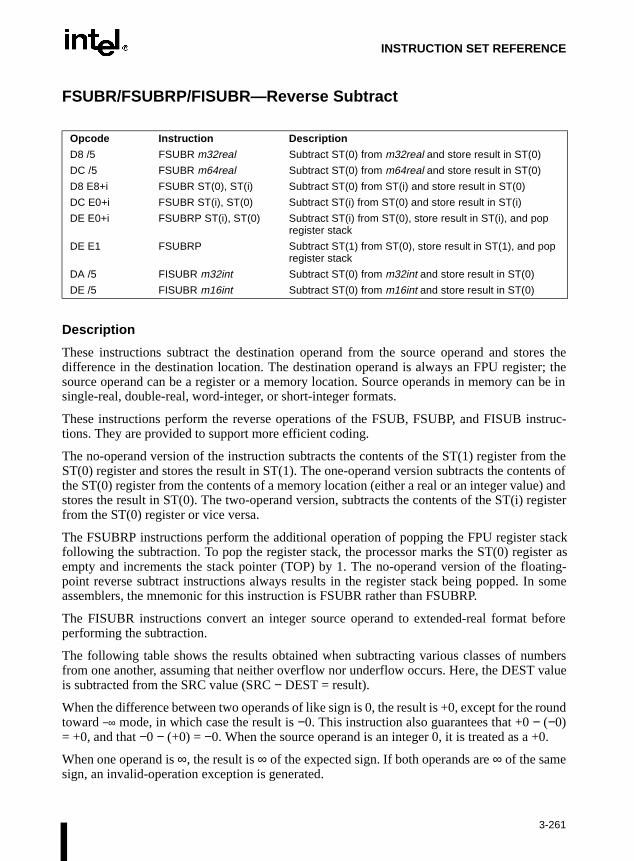
INSTRUCTION SET REFERENCE
FSUBR/FSUBRP/FISUBR—Reverse Subtract
Description
These instructions subtract the destination operand from the source operand and stores thedifference in the destination location. The destination operand is always an FPU register; thesource operand can be a register or a memory location. Source operands in memory can be insingle-real, double-real, word-integer, or short-integer formats.
These instructions perform the reverse operations of the FSUB, FSUBP, and FISUB instruc-tions. They are provided to support more efficient coding.
The no-operand version of the instruction subtracts the contents of the ST(1) register from theST(0) register and stores the result in ST(1). The one-operand version subtracts the contents ofthe ST(0) register from the contents of a memory location (either a real or an integer value) andstores the result in ST(0). The two-operand version, subtracts the contents of the ST(i) registerfrom the ST(0) register or vice versa.
The FSUBRP instructions perform the additional operation of popping the FPU register stackfollowing the subtraction. To pop the register stack, the processor marks the ST(0) register asempty and increments the stack pointer (TOP) by 1. The no-operand version of the floating-point reverse subtract instructions always results in the register stack being popped. In someassemblers, the mnemonic for this instruction is FSUBR rather than FSUBRP.
The FISUBR instructions convert an integer source operand to extended-real format beforeperforming the subtraction.
The following table shows the results obtained when subtracting various classes of numbersfrom one another, assuming that neither overflow nor underflow occurs. Here, the DEST valueis subtracted from the SRC value (SRC − DEST = result).
When the difference between two operands of like sign is 0, the result is +0, except for the roundtoward −∞ mode, in which case the result is −0. This instruction also guarantees that +0 − (−0)= +0, and that −0 − (+0) = −0. When the source operand is an integer 0, it is treated as a +0.
When one operand is ∞, the result is ∞ of the expected sign. If both operands are ∞ of the samesign, an invalid-operation exception is generated.
Opcode Instruction Description
D8 /5 FSUBR m32real Subtract ST(0) from m32real and store result in ST(0)
DC /5 FSUBR m64real Subtract ST(0) from m64real and store result in ST(0)
D8 E8+i FSUBR ST(0), ST(i) Subtract ST(0) from ST(i) and store result in ST(0)
DC E0+i FSUBR ST(i), ST(0) Subtract ST(i) from ST(0) and store result in ST(i)
DE E0+i FSUBRP ST(i), ST(0) Subtract ST(i) from ST(0), store result in ST(i), and pop register stack
DE E1 FSUBRP Subtract ST(1) from ST(0), store result in ST(1), and pop register stack
DA /5 FISUBR m32int Subtract ST(0) from m32int and store result in ST(0)
DE /5 FISUBR m16int Subtract ST(0) from m16int and store result in ST(0)
3-261

INSTRUCTION SET REFERENCE
FSUBR/FSUBRP/FISUBR—Reverse Subtract (Continued)
NOTES:
F Means finite-real number.
I Means integer.
* Indicates floating-point invalid-arithmetic-operand (#IA) exception.
Operation
IF instruction is FISUBRTHEN
DEST ← ConvertExtendedReal(SRC) − DEST;ELSE (* source operand is real number *)
DEST ← SRC − DEST;FI;IF instruction = FSUBRP
THEN PopRegisterStack
FI;
FPU Flags Affected
C1 Set to 0 if stack underflow occurred.
Indicates rounding direction if the inexact-result exception (#P) fault isgenerated: 0 = not roundup; 1 = roundup.
C0, C2, C3 Undefined.
SRC
−∞ −F or −I −0 +0 +F or +I +∞ NaN
−∞ * +∞ +∞ +∞ +∞ +∞ NaN
−F −∞ ±F or ±0 −DEST −DEST +F +∞ NaN
DEST −0 −∞ SRC ±0 +0 SRC +∞ NaN
+0 −∞ SRC −0 ±0 SRC +∞ NaN
+F −∞ −F −DEST −DEST ±F or ±0 +∞ NaN
+∞ −∞ −∞ −∞ −∞ −∞ * NaN
NaN NaN NaN NaN NaN NaN NaN NaN
3-262

INSTRUCTION SET REFERENCE
FSUBR/FSUBRP/FISUBR—Reverse Subtract (Continued)
Floating-Point Exceptions
#IS Stack underflow occurred.
#IA Operand is an sNaN value or unsupported format.
Operands are infinities of like sign.
#D Source operand is a denormal value.
#U Result is too small for destination format.
#O Result is too large for destination format.
#P Value cannot be represented exactly in destination format.
Protected Mode Exceptions
#GP(0) If a memory operand effective address is outside the CS, DS, ES, FS, orGS segment limit.
If the DS, ES, FS, or GS register is used to access memory and it containsa null segment selector.
#SS(0) If a memory operand effective address is outside the SS segment limit.
#NM EM or TS in CR0 is set.
#PF(fault-code) If a page fault occurs.
#AC(0) If alignment checking is enabled and an unaligned memory reference ismade while the current privilege level is 3.
Real-Address Mode Exceptions
#GP If a memory operand effective address is outside the CS, DS, ES, FS, orGS segment limit.
#SS If a memory operand effective address is outside the SS segment limit.
#NM EM or TS in CR0 is set.
3-263

INSTRUCTION SET REFERENCE
FSUBR/FSUBRP/FISUBR—Reverse Subtract (Continued)
Virtual-8086 Mode Exceptions
#GP(0) If a memory operand effective address is outside the CS, DS, ES, FS, orGS segment limit.
#SS(0) If a memory operand effective address is outside the SS segment limit.
#NM EM or TS in CR0 is set.
#PF(fault-code) If a page fault occurs.
#AC(0) If alignment checking is enabled and an unaligned memory reference ismade.
3-264

INSTRUCTION SET REFERENCE
ecksf theunor-
FTST—TEST
Description
This instruction compares the value in the ST(0) register with 0.0 and sets the condition codeflags C0, C2, and C3 in the FPU status word according to the results (refer to the table below).
This instruction performs an “unordered comparison.” An unordered comparison also chthe class of the numbers being compared (refer to “FXAM—Examine” in this chapter). Ivalue in register ST(0) is a NaN or is in an undefined format, the condition flags are set to “dered” and the invalid operation exception is generated.
The sign of zero is ignored, so that –0.0 = +0.0.
Operation
CASE (relation of operands) OFNot comparable: C3, C2, C0 ← 111;ST(0) > 0.0: C3, C2, C0 ← 000;ST(0) < 0.0: C3, C2, C0 ← 001;ST(0) = 0.0: C3, C2, C0 ← 100;
ESAC;
FPU Flags Affected
C1 Set to 0 if stack underflow occurred; otherwise, cleared to 0.
C0, C2, C3 Refer to above table.
Floating-Point Exceptions
#IS Stack underflow occurred.
#IA The source operand is a NaN value or is in an unsupported format.
#D The source operand is a denormal value.
Opcode Instruction Description
D9 E4 FTST Compare ST(0) with 0.0.
Condition C3 C2 C0
ST(0) > 0.0 0 0 0
ST(0) < 0.0 0 0 1
ST(0) = 0.0 1 0 0
Unordered 1 1 1
3-265

INSTRUCTION SET REFERENCE
FTST—TEST (Continued)
Protected Mode Exceptions
#NM EM or TS in CR0 is set.
Real-Address Mode Exceptions
#NM EM or TS in CR0 is set.
Virtual-8086 Mode Exceptions
#NM EM or TS in CR0 is set.
3-266

INSTRUCTION SET REFERENCE
fer tos asalid- in an
do notceptionformat.
cep-
d theo pope stack
FUCOM/FUCOMP/FUCOMPP—Unordered Compare Real
Description
These instructions perform an unordered comparison of the contents of register ST(0) and ST(i)and sets condition code flags C0, C2, and C3 in the FPU status word according to the results(refer to the table below). If no operand is specified, the contents of registers ST(0) and ST(1)are compared. The sign of zero is ignored, so that –0.0 = +0.0.
NOTE:
* Flags not set if unmasked invalid-arithmetic-operand (#IA) exception is generated.
An unordered comparison checks the class of the numbers being compared (re“FXAM—Examine” in this chapter). The FUCOM instructions perform the same operationthe FCOM instructions. The only difference is that the FUCOM instructions raise the invarithmetic-operand exception (#IA) only when either or both operands are an sNaN or areunsupported format; qNaNs cause the condition code flags to be set to unordered, butcause an exception to be generated. The FCOM instructions raise an invalid-operation exwhen either or both of the operands are a NaN value of any kind or are in an unsupported
As with the FCOM instructions, if the operation results in an invalid-arithmetic-operand extion being raised, the condition code flags are set only if the exception is masked.
The FUCOMP instruction pops the register stack following the comparison operation anFUCOMPP instruction pops the register stack twice following the comparison operation. Tthe register stack, the processor marks the ST(0) register as empty and increments thpointer (TOP) by 1.
Opcode Instruction Description
DD E0+i FUCOM ST(i) Compare ST(0) with ST(i)
DD E1 FUCOM Compare ST(0) with ST(1)
DD E8+i FUCOMP ST(i) Compare ST(0) with ST(i) and pop register stack
DD E9 FUCOMP Compare ST(0) with ST(1) and pop register stack
DA E9 FUCOMPP Compare ST(0) with ST(1) and pop register stack twice
Comparison Results C3 C2 C0
ST0 > ST(i) 0 0 0
ST0 < ST(i) 0 0 1
ST0 = ST(i) 1 0 0
Unordered 1 1 1
3-267

INSTRUCTION SET REFERENCE
FUCOM/FUCOMP/FUCOMPP—Unordered Compare Real (Continued)
Operation
CASE (relation of operands) OFST > SRC: C3, C2, C0 ← 000;ST < SRC: C3, C2, C0 ← 001;ST = SRC: C3, C2, C0 ← 100;
ESAC;IF ST(0) or SRC = QNaN, but not SNaN or unsupported format
THEN C3, C2, C0 ← 111;
ELSE (* ST(0) or SRC is SNaN or unsupported format *) #IA;IF FPUControlWord.IM = 1
THEN C3, C2, C0 ← 111;
FI;FI;IF instruction = FUCOMP
THEN PopRegisterStack;
FI;IF instruction = FUCOMPP
THEN PopRegisterStack; PopRegisterStack;
FI;
FPU Flags Affected
C1 Set to 0 if stack underflow occurred.
C0, C2, C3 Refer to table on previous page.
Floating-Point Exceptions
#IS Stack underflow occurred.
#IA One or both operands are sNaN values or have unsupported formats.Detection of a qNaN value in and of itself does not raise an invalid-operand exception.
#D One or both operands are denormal values.
3-268

INSTRUCTION SET REFERENCE
FUCOM/FUCOMP/FUCOMPP—Unordered Compare Real (Continued)
Protected Mode Exceptions
#NM EM or TS in CR0 is set.
Real-Address Mode Exceptions
#NM EM or TS in CR0 is set.
Virtual-8086 Mode Exceptions
#NM EM or TS in CR0 is set.
3-269
INSTRUCTION SET REFERENCE
FWAIT—Wait
Refer to entry for WAIT/FWAIT—Wait.
3-270

INSTRUCTION SET REFERENCE
FXAM—Examine
Description
This instruction examines the contents of the ST(0) register and sets the condition code flags C0,C2, and C3 in the FPU status word to indicate the class of value or number in the register (referto the table below).
.
The C1 flag is set to the sign of the value in ST(0), regardless of whether the register is emptyor full.
Operation
C1 ← sign bit of ST; (* 0 for positive, 1 for negative *)CASE (class of value or number in ST(0)) OF
Unsupported:C3, C2, C0 ← 000;NaN: C3, C2, C0 ← 001;Normal: C3, C2, C0 ← 010;Infinity: C3, C2, C0 ← 011;Zero: C3, C2, C0 ← 100;Empty: C3, C2, C0 ← 101;Denormal: C3, C2, C0 ← 110;
ESAC;
FPU Flags Affected
C1 Sign of value in ST(0).
C0, C2, C3 Refer to table above.
Opcode Instruction Description
D9 E5 FXAM Classify value or number in ST(0)
Class C3 C2 C0
Unsupported 0 0 0
NaN 0 0 1
Normal finite number 0 1 0
Infinity 0 1 1
Zero 1 0 0
Empty 1 0 1
Denormal number 1 1 0
3-271

INSTRUCTION SET REFERENCE
FXAM—Examine (Continued)
Floating-Point Exceptions
None.
Protected Mode Exceptions
#NM EM or TS in CR0 is set.
Real-Address Mode Exceptions
#NM EM or TS in CR0 is set.
Virtual-8086 Mode Exceptions
#NM EM or TS in CR0 is set.
3-272

INSTRUCTION SET REFERENCE
FXCH—Exchange Register Contents
Description
This instruction exchanges the contents of registers ST(0) and ST(i). If no source operand isspecified, the contents of ST(0) and ST(1) are exchanged.
This instruction provides a simple means of moving values in the FPU register stack to the topof the stack [ST(0)], so that they can be operated on by those floating-point instructions that canonly operate on values in ST(0). For example, the following instruction sequence takes thesquare root of the third register from the top of the register stack:
FXCH ST(3);FSQRT;FXCH ST(3);
Operation
IF number-of-operands is 1THEN
temp ← ST(0);ST(0) ← SRC;SRC ← temp;
ELSEtemp ← ST(0);ST(0) ← ST(1);ST(1) ← temp;
FPU Flags Affected
C1 Set to 0 if stack underflow occurred; otherwise, cleared to 0.
C0, C2, C3 Undefined.
Floating-Point Exceptions
#IS Stack underflow occurred.
Protected Mode Exceptions
#NM EM or TS in CR0 is set.
Opcode Instruction Description
D9 C8+i FXCH ST(i) Exchange the contents of ST(0) and ST(i)
D9 C9 FXCH Exchange the contents of ST(0) and ST(1)
3-273

INSTRUCTION SET REFERENCE
FXCH—Exchange Register Contents (Continued)
Real-Address Mode Exceptions
#NM EM or TS in CR0 is set.
Virtual-8086 Mode Exceptions
#NM EM or TS in CR0 is set.
3-274

INSTRUCTION SET REFERENCE
ming2byte.
andmory,
FXRSTOR—Restore FP and MMX ™ State and Streaming SIMD Extension State
Description
The FXRSTOR instruction reloads the FP and MMX™ technology state, and the StreaSIMD Extension state (environment and registers), from the memory area defined by m51This data should have been written by a previous FXSAVE.
The floating-point, MMX™ technology, and Streaming SIMD Extension environment registers consist of the following data structure (little-endian byte order as arranged in mewith byte offset into row described by right column):
Opcode Instruction Description
0F,AE,/1 FXRSTORm512byte
Load FP and MMX™ technology and Streaming SIMD Extension state from m512byte.
3-275

INSTRUCTION SET REFERENCE
FXRSTOR—Restore FP And MMX ™ State and Streaming SIMD Extension State (Continued)
15 14 13 12 11 10 9 8 7 6 5 4 3 2 1 0
Rsrvd CS IP FOP FTW FSW FCW 0
Reserved MXCSR Rsrvd DS DP 16
Reserved ST0/MM0 32
Reserved ST1/MM1 48
Reserved ST2/MM2 64
Reserved ST3/MM3 80
Reserved ST4/MM4 96
Reserved ST5/MM5 112
Reserved ST6/MM6 128
Reserved ST7/MM7 144
XMM0 160
XMM1 176
XMM2 192
XMM3 208
XMM4 224
XMM5 240
XMM6 256
XMM7 272
Reserved 288
Reserved 304
Reserved 320
Reserved 336
Reserved 352
Reserved 368
Reserved 384
Reserved 400
Reserved 416
Reserved 432
Reserved 448
Reserved 464
Reserved 480
Reserved 496
3-276

INSTRUCTION SET REFERENCE
FXRSTOR—Restore FP And MMX ™ State And Streaming SIMD Extension State (Continued)
Three fields in the floating-point save area contain reserved bits that are not indicated in thetable:
FOP The lower 11-bits contain the opcode, upper 5-bits are reserved.
IP & DP 32-bit mode: 32-bit IP-offset.
16-bit mode: lower 16 bits are IP-offset and upper 16 bits are reserved.
If the MXCSR state contains an unmasked exception with a corresponding status flag also set,loading it will not result in a floating-point error condition being asserted. Only the next occur-rence of this unmasked exception will result in the error condition being asserted.
Some bits of MXCSR (bits 31-16 and bit 6) are defined as reserved and cleared; attempting towrite a non-zero value to these bits will result in a general protection exception.
FXRSTOR does not flush pending x87-FP exceptions, unlike FRSTOR. To check and raiseexceptions when loading a new operating environment, use FWAIT after FXRSTOR.
The Streaming SIMD Extension fields in the save image (XMM0-XMM7 and MXCSR) will notbe loaded into the processor if the CR4.OSFXSR bit is not set. This CR4 bit must be set in orderto enable execution of Streaming SIMD Extension.
Operation
FP and MMX™ technology state and Streaming SIMD Extension state = m512byte;
Exceptions
#AC If exception detection is disabled, a general protection exception issignalled if the address is not aligned on 16-byte boundary. Note that if#AC is enabled (and CPL is 3), signalling of #AC is not guaranteed andmay vary with implementation. In all implementations where #AC is notsignalled, a general protection fault will instead be signalled. In addition,the width of the alignment check when #AC is enabled may also vary withimplementation; for instance, for a given implementation, #AC might besignalled for a 2-byte misalignment, whereas #GP might be signalled forall other misalignments (4-/8-/16-byte). Invalid opcode exception ifinstruction is preceded by a LOCK override prefix. General protectionfault if reserved bits of MXCSR are loaded with non-zero values.
Numeric Exceptions
None.
3-277
INSTRUCTION SET REFERENCE
FXRSTOR—Restore FP And MMX ™ State And Streaming SIMD Extension State (Continued)
Protected Mode Exceptions
#GP(0) For an illegal memory operand effective address in the CS, DS, ES, FS, orGS segments, or if an attempt is made to load non-zero values to reservedbits in the MXCSR field.
#SS(0) For an illegal address in the SS segment.
#PF (fault-code) For a page fault.
#NM If CR0.EM = 1.
#NM If TS bit in CR0 is set.
#AC For unaligned memory reference. To enable #AC exceptions, three condi-tions must be true(CR0.AM is set; EFLAGS.AC is set; current CPL is 3).
Real Address Mode Exceptions
Interrupt 13 If any part of the operand would lie outside of the effective address spacefrom 0 to 0FFFFH.
#NM If CR0.EM = 1.
#NM If TS bit in CR0 is set.
Virtual 8086 Mode Exceptions
Same exceptions as in Real Address Mode.
#AC For unaligned memory reference if the current privilege level is 3.
#PF (fault-code) For a page fault.
Comments
State saved with FXSAVE and restored with FRSTOR, and state saved with FSAVE and restoredwith FXRSTOR, will result in incorrect restoration of state in the processor. The address sizeprefix will have the usual effect on address calculation, but will have no effect on the format ofthe FXRSTOR image.
The use of Repeat (F2H, F3H) and Operand-size (66H) prefixes with FXRSTOR is reserved.Different processor implementations may handle these prefixes differently. Usage of theseprefixes with FXRSTOR risks incompatibility with future processors.
3-278

INSTRUCTION SET REFERENCE
ed bytionssornsion to maxi- byte
FXSAVE—Store FP and MMX ™ State and Streaming SIMD Extension State
Description
The FXSAVE instruction writes the current FP and MMX™ technology state, and StreamingSIMD Extension state (environment and registers), to the specified destination definm512byte. It does this without checking for pending unmasked floating-point excep(similar to the operation of FNSAVE). Unlike the FSAVE/FNSAVE instructions, the procesretains the contents of the FP and MMX™ technology state and Streaming SIMD Extestate in the processor after the state has been saved. This instruction has been optimizedmize floating-point save performance. The save data structure is as follows (little-endianorder as arranged in memory, with byte offset into row described by right column):
Opcode Instruction Description
0F,AE,/0 FXSAVEm512byte
Store FP and MMX™ technology state and Streaming SIMD Extension state to m512byte.
3-279

INSTRUCTION SET REFERENCE
FXSAVE—Store FP and MMX ™ State And Streaming SIMD Extension State (Continued)
15 14 13 12 11 10 9 8 7 6 5 4 3 2 1 0
Rsrvd CS IP FOP FTW FSW FCW 0
Reserved MXCSR Rsrvd DS DP 16
Reserved ST0/MM0 32
Reserved ST1/MM1 48
Reserved ST2/MM2 64
Reserved ST3/MM3 80
Reserved ST4/MM4 96
Reserved ST5/MM5 112
Reserved ST6/MM6 128
Reserved ST7/MM7 144
XMM0 160
XMM1 176
XMM2 192
XMM3 208
XMM4 224
XMM5 240
XMM6 256
XMM7 272
Reserved 288
Reserved 304
Reserved 320
Reserved 336
Reserved 352
Reserved 368
Reserved 384
Reserved 400
Reserved 416
Reserved 432
Reserved 448
Reserved 464
Reserved 480
Reserved 496
3-280

INSTRUCTION SET REFERENCE
andclean"xecute
ield. d first,2 are
and 10 the
FXSAVE—Store FP and MMX ™ State And Streaming SIMD Extension State (Continued)
Three fields in the floating-point save area contain reserved bits that are not indicated in thetable:
FOP: The lower 11-bits contain the opcode, upper 5-bits are reserved.
IP & DP: 32-bit mode: 32-bit IP-offset.
16-bit mode: lower 16 bits are IP-offset and upper 16 bits are reserved.
The FXSAVE instruction is used when an operating system needs to perform a context switchor when an exception handler needs to use the floating-point, MMX™ technology,Streaming SIMD Extension units. It cannot be used by an application program to pass a "FP state to a procedure, since it retains the current state. An application must explicitly ean FINIT instruction after FXSAVE to provide for this functionality.
All of the x87-FP fields retain the same internal format as in FSAVE except for FTW.
Unlike FSAVE, FXSAVE saves only the FTW valid bits rather than the entire x87-FP FTW fThe FTW bits are saved in a non-TOS relative order, which means that FR0 is always savefollowed by FR1, FR2 and so forth. As an example, if TOS=4 and only ST0, ST1 and STvalid, FSAVE saves the FTW field in the following format:
ST3 ST2 ST1 ST0 ST7 ST6 ST5 ST4 (TOS=4)
FR7 FR6 FR5 FR4 FR3 FR2 FR1 FR0
11 xx xx xx 11 11 11 11
where xx is one of (00, 01, 10). (11) indicates an empty stack elements, and the 00, 01, indicate Valid, Zero, and Special, respectively. In this example, FXSAVE would savefollowing vector:
FR7 FRits6 FR5 FR4 FR3 FR2 FR1 FR0
0 1 1 1 0 0 0 0
3-281

INSTRUCTION SET REFERENCE
ing the
gnifi-nifi-
t be
se a the
the
e
FXSAVE—Store FP and MMX ™ State And Streaming SIMD Extension State (Continued)
The FSAVE format for FTW can be recreated from the FTW valid bits and the stored 80-bit FPdata (assuming the stored data was not the contents of MMX™ technology registers) usfollowing table:
The J-bit is defined to be the 1-bit binary integer to the left of the decimal place in the sicand. The M-bit is defined to be the most significant bit of the fractional portion of the sigcand (i.e., the bit immediately to the right of the decimal place).
When the M- bit is the most significant bit of the fractional portion of the significand, it mus0 if the fraction is all 0’s.
If the FXSAVE instruction is immediately preceded by an FP instruction which does not umemory operand, then the FXSAVE instruction does not write/update the DP field, inFXSAVE image.
MXCSR holds the contents of the SIMD floating-point Control/Status Register. Refer toLDMXCSR instruction for a full description of this field.
The fields XMM0-XMM7 contain the content of registers XMM0-XMM7 in exactly the samformat as they exist in the registers.
Exponentall 1’s
Exponentall 0’s
Fractionall 0’s
J and Mbits
FTW valid bit
x87 FTW
0 0 0 0x 1 Special 10
0 0 0 1x 1 Valid 00
0 0 1 00 1 Special 10
0 0 1 10 1 Valid 00
0 1 0 0x 1 Special 10
0 1 0 1x 1 Special 10
0 1 1 00 1 Zero 01
0 1 1 10 1 Special 10
1 0 0 1x 1 Special 10
1 0 0 1x 1 Special 10
1 0 1 00 1 Special 10
1 0 1 10 1 Special 10
For all legal combinations above 0 Empty 11
3-282

INSTRUCTION SET REFERENCE
FXSAVE—Store FP and MMX ™ State And Streaming SIMD Extension State (Continued)
The Streaming SIMD Extension fields in the save image (XMM0-XMM7 and MXCSR) maynot be loaded into the processor if the CR4.OSFXSR bit is not set. This CR4 bit must be set inorder to enable execution of Streaming SIMD Extensions.
The destination m512byte is assumed to be aligned on a 16-byte boundary. If m512byte is notaligned on a 16-byte boundary, FXSAVE generates a general protection exception.
Operation
m512byte = FP and MMX™ technology state and Streaming SIMD Extension state;
Exceptions
#AC If exception detection is disabled, a general protection exception issignalled if the address is not aligned on 16-byte boundary. Note that if#AC is enabled (and CPL is 3), signalling of #AC is not guaranteed andmay vary with implementation. In all implementations where #AC is notsignalled, a general protection fault will instead be signalled. In addition,the width of the alignment check when #AC is enabled may also vary withimplementation; for instance, for a given implementation, #AC might besignalled for a 2-byte misalignment, whereas #GP might be signalled forall other misalignments (4-/8-/16-byte). Invalid opcode exception ifinstruction is preceded by a LOCK override prefix.
Numeric Exceptions
Invalid, Precision.
Protected Mode Exceptions
#GP(0) For an illegal memory operand effective address in the CS, DS, ES, FS, orGS segments.
#SS(0) For an illegal address in the SS segment.
#PF (fault-code) For a page fault.
#NM If CR0.EM = 1.
#NM If TS bit in CR0 is set.
#AC For unaligned memory reference. To enable #AC exceptions, three condi-tions must be true(CR0.AM is set; EFLAGS.AC is set; current CPL is 3).
3-283

INSTRUCTION SET REFERENCE
FXSAVE—Store FP and MMX ™ State And Streaming SIMD Extension State (Continued)
Real Address Mode Exceptions
Interrupt 13 If any part of the operand would lie outside of the effective address spacefrom 0 to 0FFFFH.
#NM If CR0.EM = 1.
#NM If TS bit in CR0 is set.
Virtual 8086 Mode Exceptions
Same exceptions as in Real Address Mode.
#AC For unaligned memory reference if the current privilege level is 3.
#PF (fault-code) For a page fault.
Comments
State saved with FXSAVE and restored with FRSTOR, and state saved with FSAVE and restoredwith FXRSTOR, will result in incorrect restoration of state in the processor. The address sizeprefix will have the usual effect on address calculation, but will have no effect on the format ofthe FXSAVE image.
The use of Repeat (F2H, F3H) and Operand-size (66H) prefixes with FXSAVE is reserved.Different processor implementations may handle these prefixes differently. Usage of theseprefixes with FXSAVE risks incompatibility with future processors.
3-284

INSTRUCTION SET REFERENCE
ressedecom-
aling-real
ro, and is
d.
FXTRACT—Extract Exponent and Significand
Description
This instruction separates the source value in the ST(0) register into its exponent and signifi-cand, stores the exponent in ST(0), and pushes the significand onto the register stack. Followingthis operation, the new top-of-stack register ST(0) contains the value of the original significandexpressed as a real number. The sign and significand of this value are the same as those foundin the source operand, and the exponent is 3FFFH (biased value for a true exponent of zero). TheST(1) register contains the value of the original operand’s true (unbiased) exponent expas a real number. (The operation performed by this instruction is a superset of the IEEE-rmended logb(x) function.)
This instruction and the F2XM1 instruction are useful for performing power and range scoperations. The FXTRACT instruction is also useful for converting numbers in extendedformat to decimal representations (e.g., for printing or displaying).
If the floating-point zero-divide exception (#Z) is masked and the source operand is zeexponent value of –∞ is stored in register ST(1) and 0 with the sign of the source operanstored in register ST(0).
Operation
TEMP ← Significand(ST(0));ST(0) ← Exponent(ST(0));TOP← TOP − 1;ST(0) ← TEMP;
FPU Flags Affected
C1 Set to 0 if stack underflow occurred; set to 1 if stack overflow occurre
C0, C2, C3 Undefined.
Floating-Point Exceptions
#IS Stack underflow occurred.
Stack overflow occurred.
#IA Source operand is an sNaN value or unsupported format.
#Z ST(0) operand is ±0.
#D Source operand is a denormal value.
Opcode Instruction Description
D9 F4 FXTRACT Separate value in ST(0) into exponent and significand, store exponent in ST(0), and push the significand onto the register stack.
3-285

INSTRUCTION SET REFERENCE
FXTRACT—Extract Exponent and Significand (Continued)
Protected Mode Exceptions
#NM EM or TS in CR0 is set.
Real-Address Mode Exceptions
#NM EM or TS in CR0 is set.
Virtual-8086 Mode Exceptions
#NM EM or TS in CR0 is set.
3-286

INSTRUCTION SET REFERENCE
FYL2X—Compute y ∗ log 2x
Description
This instruction calculates (ST(1) ∗ log2 (ST(0))), stores the result in resister ST(1), and pops theFPU register stack. The source operand in ST(0) must be a non-zero positive number.
The following table shows the results obtained when taking the log of various classes ofnumbers, assuming that neither overflow nor underflow occurs.
NOTES:
F Means finite-real number.
* Indicates floating-point invalid-operation (#IA) exception.
** Indicates floating-point zero-divide (#Z) exception.
If the divide-by-zero exception is masked and register ST(0) contains ±0, the instruction returns∞ with a sign that is the opposite of the sign of the source operand in register ST(1).
The FYL2X instruction is designed with a built-in multiplication to optimize the calculation oflogarithms with an arbitrary positive base (b):
logbx = (log2b)–1 ∗ log2x
Operation
ST(1) ← ST(1) ∗ log2ST(0);PopRegisterStack;
Opcode Instruction Description
D9 F1 FYL2X Replace ST(1) with (ST(1) ∗ log2ST(0)) and pop the register stack
ST(0)
−∞ −F ±0 +0 < +F < +1 +1 +F > +1 +∞ NaN
−∞ * * +∞ +∞ * −∞ −∞ NaN
ST(1) −F * * ** +F −0 −F −∞ NaN
−0 * * * +0 −0 −0 * NaN
+0 * * * −0 +0 +0 * NaN
+F * * ** −F +0 +F +∞ NaN
+∞ * * −∞ −∞ ∗ +∞ +∞ NaN
NaN NaN NaN NaN NaN NaN NaN NaN NaN
3-287

INSTRUCTION SET REFERENCE
FYL2X—Compute y ∗ log 2x (Continued)
FPU Flags Affected
C1 Set to 0 if stack underflow occurred.
Indicates rounding direction if the inexact-result exception (#P) is gener-ated: 0 = not roundup; 1 = roundup.
C0, C2, C3 Undefined.
Floating-Point Exceptions
#IS Stack underflow occurred.
#IA Either operand is an sNaN or unsupported format.
Source operand in register ST(0) is a negative finite value (not −0).
#Z Source operand in register ST(0) is ±0.
#D Source operand is a denormal value.
#U Result is too small for destination format.
#O Result is too large for destination format.
#P Value cannot be represented exactly in destination format.
Protected Mode Exceptions
#NM EM or TS in CR0 is set.
Real-Address Mode Exceptions
#NM EM or TS in CR0 is set.
Virtual-8086 Mode Exceptions
#NM EM or TS in CR0 is set.
3-288

INSTRUCTION SET REFERENCE
FYL2XP1—Compute y ∗ log 2(x +1)
Description
This instruction calculates the log epsilon (ST(1) ∗ log2(ST(0) + 1.0)), stores the result in registerST(1), and pops the FPU register stack. The source operand in ST(0) must be in the range:
The source operand in ST(1) can range from −∞ to +∞. If the ST(0) operand is outside of itsacceptable range, the result is undefined and software should not rely on an exception beinggenerated. Under some circumstances exceptions may be generated when ST(0) is out of range,but this behavior is implementation specific and not guaranteed.
The following table shows the results obtained when taking the log epsilon of various classes ofnumbers, assuming that underflow does not occur.
NOTES:
F Means finite-real number.
* Indicates floating-point invalid-operation (#IA) exception.
This instruction provides optimal accuracy for values of epsilon [the value in register ST(0)] thatare close to 0. When the epsilon value (ε) is small, more significant digits can be retained byusing the FYL2XP1 instruction than by using (ε+1) as an argument to the FYL2X instruction.The (ε+1) expression is commonly found in compound interest and annuity calculations. Theresult can be simply converted into a value in another logarithm base by including a scale factorin the ST(1) source operand. The following equation is used to calculate the scale factor for aparticular logarithm base, where n is the logarithm base desired for the result of the FYL2XP1instruction: scale factor = logn 2
Opcode Instruction Description
D9 F9 FYL2XP1 Replace ST(1) with ST(1) ∗ log2(ST(0) + 1.0) and pop the register stack
ST(0)
−(1 − ( )) to −0 −0 +0 +0 to +(1 − ( )) NaN
−∞ +∞ * * −∞ NaN
ST(1) −F +F +0 −0 −F NaN
−0 +0 +0 −0 −0 NaN
+0 −0 −0 +0 +0 NaN
+F −F −0 +0 +F NaN
+∞ −∞ * * +∞ NaN
NaN NaN NaN NaN NaN NaN
1 2 2⁄–( ) )to 1 2 2⁄–( )–
2 2⁄ 2 2⁄
3-289

INSTRUCTION SET REFERENCE
FYL2XP1—Compute y ∗ log 2(x +1) (Continued)
Operation
ST(1) ← ST(1) ∗ log2(ST(0) + 1.0);PopRegisterStack;
FPU Flags Affected
C1 Set to 0 if stack underflow occurred.
Indicates rounding direction if the inexact-result exception (#P) isgenerated: 0 = not roundup; 1 = roundup.
C0, C2, C3 Undefined.
Floating-Point Exceptions
#IS Stack underflow occurred.
#IA Either operand is an sNaN value or unsupported format.
#D Source operand is a denormal value.
#U Result is too small for destination format.
#O Result is too large for destination format.
#P Value cannot be represented exactly in destination format.
Protected Mode Exceptions
#NM EM or TS in CR0 is set.
Real-Address Mode Exceptions
#NM EM or TS in CR0 is set.
Virtual-8086 Mode Exceptions
#NM EM or TS in CR0 is set.
3-290

INSTRUCTION SET REFERENCE
HLT—Halt
Description
This instruction stops instruction execution and places the processor in a HALT state. Anenabled interrupt, NMI, or a reset will resume execution. If an interrupt (including NMI) is usedto resume execution after a HLT instruction, the saved instruction pointer (CS:EIP) points to theinstruction following the HLT instruction.
The HLT instruction is a privileged instruction. When the processor is running in protected orvirtual-8086 mode, the privilege level of a program or procedure must be 0 to execute the HLTinstruction.
Operation
Enter Halt state;
Flags Affected
None.
Protected Mode Exceptions
#GP(0) If the current privilege level is not 0.
Real-Address Mode Exceptions
None.
Virtual-8086 Mode Exceptions
#GP(0) If the current privilege level is not 0.
Opcode Instruction Description
F4 HLT Halt
3-291

INSTRUCTION SET REFERENCE
IDIV—Signed Divide
Description
This instruction divides (signed) the value in the AL, AX, or EAX register by the source operandand stores the result in the AX, DX:AX, or EDX:EAX registers. The source operand can be ageneral-purpose register or a memory location. The action of this instruction depends on theoperand size, as shown in the following table:
Non-integral results are truncated (chopped) towards 0. The sign of the remainder is always thesame as the sign of the dividend. The absolute value of the remainder is always less than theabsolute value of the divisor. Overflow is indicated with the #DE (divide error) exception ratherthan with the OF (overflow) flag.
Operation
IF SRC = 0THEN #DE; (* divide error *)
FI;IF OpernadSize = 8 (* word/byte operation *)
THENtemp ← AX / SRC; (* signed division *)IF (temp > 7FH) OR (temp < 80H) (* if a positive result is greater than 7FH or a negative result is less than 80H *)
THEN #DE; (* divide error *) ;ELSE
AL ← temp;AH ← AX SignedModulus SRC;
FI;
Opcode Instruction Description
F6 /7 IDIV r/m8 Signed divide AX (where AH must contain sign-extension of AL) by r/m byte. (Results: AL=Quotient, AH=Remainder)
F7 /7 IDIV r/m16 Signed divide DX:AX (where DX must contain sign-extension of AX) by r/m word. (Results: AX=Quotient, DX=Remainder)
F7 /7 IDIV r/m32 Signed divide EDX:EAX (where EDX must contain sign-extension of EAX) by r/m doubleword. (Results: EAX=Quotient, EDX=Remainder)
Operand Size Dividend Divisor Quotient Remainder Quotient Range
Word/byte AX r/m8 AL AH −128 to +127
Doubleword/word DX:AX r/m16 AX DX −32,768 to +32,767
Quadword/doubleword EDX:EAX r/m32 EAX EDX −231 to 232 − 1
3-292

INSTRUCTION SET REFERENCE
IDIV—Signed Divide (Continued)
ELSEIF OpernadSize = 16 (* doubleword/word operation *)
THENtemp ← DX:AX / SRC; (* signed division *)IF (temp > 7FFFH) OR (temp < 8000H) (* if a positive result is greater than 7FFFH *)(* or a negative result is less than 8000H *)
THEN #DE; (* divide error *) ;ELSE
AX ← temp;DX ← DX:AX SignedModulus SRC;
FI;ELSE (* quadword/doubleword operation *)
temp ← EDX:EAX / SRC; (* signed division *)IF (temp > 7FFFFFFFH) OR (temp < 80000000H) (* if a positive result is greater than 7FFFFFFFH *)(* or a negative result is less than 80000000H *)
THEN #DE; (* divide error *) ;ELSE
EAX ← temp;EDX ← EDXE:AX SignedModulus SRC;
FI;FI;
FI;
Flags Affected
The CF, OF, SF, ZF, AF, and PF flags are undefined.
Protected Mode Exceptions
#DE If the source operand (divisor) is 0.
The signed result (quotient) is too large for the destination.
#GP(0) If a memory operand effective address is outside the CS, DS, ES, FS, orGS segment limit.
If the DS, ES, FS, or GS register is used to access memory and it containsa null segment selector.
#SS(0) If a memory operand effective address is outside the SS segment limit.
#PF(fault-code) If a page fault occurs.
#AC(0) If alignment checking is enabled and an unaligned memory reference ismade while the current privilege level is 3.
3-293

INSTRUCTION SET REFERENCE
IDIV—Signed Divide (Continued)
Real-Address Mode Exceptions
#DE If the source operand (divisor) is 0.
The signed result (quotient) is too large for the destination.
#GP If a memory operand effective address is outside the CS, DS, ES, FS, orGS segment limit.
#SS If a memory operand effective address is outside the SS segment limit.
Virtual-8086 Mode Exceptions
#DE If the source operand (divisor) is 0.
The signed result (quotient) is too large for the destination.
#GP(0) If a memory operand effective address is outside the CS, DS, ES, FS, orGS segment limit.
#SS(0) If a memory operand effective address is outside the SS segment limit.
#PF(fault-code) If a page fault occurs.
#AC(0) If alignment checking is enabled and an unaligned memory reference ismade.
3-294

INSTRUCTION SET REFERENCE
IMUL—Signed Multiply
Description
This instruction performs a signed multiplication of two operands. This instruction has threeforms, depending on the number of operands.
• One-operand form. This form is identical to that used by the MUL instruction. Here, thesource operand (in a general-purpose register or memory location) is multiplied by thevalue in the AL, AX, or EAX register (depending on the operand size) and the product isstored in the AX, DX:AX, or EDX:EAX registers, respectively.
• Two-operand form. With this form the destination operand (the first operand) ismultiplied by the source operand (second operand). The destination operand is a general-purpose register and the source operand is an immediate value, a general-purpose register,or a memory location. The product is then stored in the destination operand location.
• Three-operand form. This form requires a destination operand (the first operand) and twosource operands (the second and the third operands). Here, the first source operand (whichcan be a general-purpose register or a memory location) is multiplied by the second sourceoperand (an immediate value). The product is then stored in the destination operand (ageneral-purpose register).
When an immediate value is used as an operand, it is sign-extended to the length of the destina-tion operand format.
Opcode Instruction Description
F6 /5 IMUL r/m8 AX← AL ∗ r/m byte
F7 /5 IMUL r/m16 DX:AX ← AX ∗ r/m word
F7 /5 IMUL r/m32 EDX:EAX ← EAX ∗ r/m doubleword
0F AF /r IMUL r16,r/m16 word register ← word register ∗ r/m word
0F AF /r IMUL r32,r/m32 doubleword register ← doubleword register ∗ r/m doubleword
6B /r ib IMUL r16,r/m16,imm8 word register ← r/m16 ∗ sign-extended immediate byte
6B /r ib IMUL r32,r/m32,imm8 doubleword register ← r/m32 ∗ sign-extended immediate byte
6B /r ib IMUL r16,imm8 word register ← word register ∗ sign-extended immediate byte
6B /r ib IMUL r32,imm8 doubleword register ← doubleword register ∗ sign-extended immediate byte
69 /r iw IMUL r16,r/m16,imm16
word register ← r/m16 ∗ immediate word
69 /r id IMUL r32,r/m32,imm32
doubleword register ← r/m32 ∗ immediate doubleword
69 /r iw IMUL r16,imm16 word register ← r/m16 ∗ immediate word
69 /r id IMUL r32,imm32 doubleword register ← r/m32 ∗ immediate doubleword
3-295

INSTRUCTION SET REFERENCE
IMUL—Signed Multiply (Continued)
The CF and OF flags are set when significant bits are carried into the upper half of the result.The CF and OF flags are cleared when the result fits exactly in the lower half of the result.
The three forms of the IMUL instruction are similar in that the length of the product is calculatedto twice the length of the operands. With the one-operand form, the product is stored exactly inthe destination. With the two- and three- operand forms, however, result is truncated to thelength of the destination before it is stored in the destination register. Because of this truncation,the CF or OF flag should be tested to ensure that no significant bits are lost.
The two- and three-operand forms may also be used with unsigned operands because the lowerhalf of the product is the same regardless if the operands are signed or unsigned. The CF and OFflags, however, cannot be used to determine if the upper half of the result is non-zero.
3-296

INSTRUCTION SET REFERENCE
IMUL—Signed Multiply (Continued)
Operation
IF (NumberOfOperands = 1)THEN IF (OperandSize = 8)
THENAX ← AL ∗ SRC (* signed multiplication *)IF ((AH = 00H) OR (AH = FFH))
THEN CF = 0; OF = 0;ELSE CF = 1; OF = 1;
FI;ELSE IF OperandSize = 16
THEN DX:AX ← AX ∗ SRC (* signed multiplication *)IF ((DX = 0000H) OR (DX = FFFFH))
THEN CF = 0; OF = 0;ELSE CF = 1; OF = 1;
FI;ELSE (* OperandSize = 32 *)
EDX:EAX ← EAX ∗ SRC (* signed multiplication *)IF ((EDX = 00000000H) OR (EDX = FFFFFFFFH))
THEN CF = 0; OF = 0;ELSE CF = 1; OF = 1;
FI;FI;
ELSE IF (NumberOfOperands = 2)THEN
temp ← DEST ∗ SRC (* signed multiplication; temp is double DEST size*)DEST ← DEST ∗ SRC (* signed multiplication *)IF temp ≠ DEST
THEN CF = 1; OF = 1;ELSE CF = 0; OF = 0;
FI;
ELSE (* NumberOfOperands = 3 *)DEST ← SRC1 ∗ SRC2 (* signed multiplication *)temp ← SRC1 ∗ SRC2 (* signed multiplication; temp is double SRC1 size *)IF temp ≠ DEST
THEN CF = 1; OF = 1;ELSE CF = 0; OF = 0;
FI;FI;
FI;
3-297

INSTRUCTION SET REFERENCE
IMUL—Signed Multiply (Continued)
Flags Affected
For the one operand form of the instruction, the CF and OF flags are set when significant bitsare carried into the upper half of the result and cleared when the result fits exactly in the lowerhalf of the result. For the two- and three-operand forms of the instruction, the CF and OF flagsare set when the result must be truncated to fit in the destination operand size and cleared whenthe result fits exactly in the destination operand size. The SF, ZF, AF, and PF flags are undefined.
Protected Mode Exceptions
#GP(0) If a memory operand effective address is outside the CS, DS, ES, FS, orGS segment limit.
If the DS, ES, FS, or GS register is used to access memory and it containsa null segment selector.
#SS(0) If a memory operand effective address is outside the SS segment limit.
#PF(fault-code) If a page fault occurs.
#AC(0) If alignment checking is enabled and an unaligned memory reference ismade while the current privilege level is 3.
Real-Address Mode Exceptions
#GP If a memory operand effective address is outside the CS, DS, ES, FS, orGS segment limit.
#SS If a memory operand effective address is outside the SS segment limit.
Virtual-8086 Mode Exceptions
#GP(0) If a memory operand effective address is outside the CS, DS, ES, FS, orGS segment limit.
#SS(0) If a memory operand effective address is outside the SS segment limit.
#PF(fault-code) If a page fault occurs.
#AC(0) If alignment checking is enabled and an unaligned memory reference ismade.
3-298

INSTRUCTION SET REFERENCE
dressl,
IN—Input from Port
Description
This instruction copies the value from the I/O port specified with the second operand (sourceoperand) to the destination operand (first operand). The source operand can be a byte-immediateor the DX register; the destination operand can be register AL, AX, or EAX, depending on thesize of the port being accessed (8, 16, or 32 bits, respectively). Using the DX register as a sourceoperand allows I/O port addresses from 0 to 65,535 to be accessed; using a byte immediateallows I/O port addresses 0 to 255 to be accessed.
When accessing an 8-bit I/O port, the opcode determines the port size; when accessing a 16- and32-bit I/O port, the operand-size attribute determines the port size.
At the machine code level, I/O instructions are shorter when accessing 8-bit I/O ports. Here, theupper eight bits of the port address will be 0.
This instruction is only useful for accessing I/O ports located in the processor’s I/O adspace. Refer to Chapter 10, Input/Output of the Intel Architecture Software Developer’s ManuaVolume 1, for more information on accessing I/O ports in the I/O address space.
Operation
IF ((PE = 1) AND ((CPL > IOPL) OR (VM = 1)))THEN (* Protected mode with CPL > IOPL or virtual-8086 mode *)
IF (Any I/O Permission Bit for I/O port being accessed = 1)THEN (* I/O operation is not allowed *)
#GP(0);ELSE ( * I/O operation is allowed *)
DEST ← SRC; (* Reads from selected I/O port *)FI;
ELSE (Real Mode or Protected Mode with CPL ≤ IOPL *)DEST ← SRC; (* Reads from selected I/O port *)
FI;
Flags Affected
None.
Opcode Instruction Description
E4 ib IN AL,imm8 Input byte from imm8 I/O port address into AL
E5 ib IN AX,imm8 Input byte from imm8 I/O port address into AX
E5 ib IN EAX,imm8 Input byte from imm8 I/O port address into EAX
EC IN AL,DX Input byte from I/O port in DX into AL
ED IN AX,DX Input word from I/O port in DX into AX
ED IN EAX,DX Input doubleword from I/O port in DX into EAX
3-299

INSTRUCTION SET REFERENCE
IN—Input from Port (Continued)
Protected Mode Exceptions
#GP(0) If the CPL is greater than (has less privilege) the I/O privilege level (IOPL)and any of the corresponding I/O permission bits in TSS for the I/O portbeing accessed is 1.
Real-Address Mode Exceptions
None.
Virtual-8086 Mode Exceptions
#GP(0) If any of the I/O permission bits in the TSS for the I/O port being accessedis 1.
3-300

INSTRUCTION SET REFERENCE
INC—Increment by 1
Description
This instruction adds one to the destination operand, while preserving the state of the CF flag.The destination operand can be a register or a memory location. This instruction allows a loopcounter to be updated without disturbing the CF flag. (Use a ADD instruction with an immediateoperand of 1 to perform an increment operation that does updates the CF flag.)
Operation
DEST ← DEST +1;
Flags Affected
The CF flag is not affected. The OF, SF, ZF, AF, and PF flags are set according to the result.
Protected Mode Exceptions
#GP(0) If the destination operand is located in a nonwritable segment.
If a memory operand effective address is outside the CS, DS, ES, FS, orGS segment limit.
If the DS, ES, FS, or GS register is used to access memory and it containsa null segment selector.
#SS(0) If a memory operand effective address is outside the SS segment limit.
#PF(fault-code) If a page fault occurs.
#AC(0) If alignment checking is enabled and an unaligned memory reference ismade while the current privilege level is 3.
Real-Address Mode Exceptions
#GP If a memory operand effective address is outside the CS, DS, ES, FS, orGS segment limit.
#SS If a memory operand effective address is outside the SS segment limit.
Opcode Instruction Description
FE /0 INC r/m8 Increment r/m byte by 1
FF /0 INC r/m16 Increment r/m word by 1
FF /0 INC r/m32 Increment r/m doubleword by 1
40+ rw INC r16 Increment word register by 1
40+ rd INC r32 Increment doubleword register by 1
3-301

INSTRUCTION SET REFERENCE
INC—Increment by 1 (Continued)
Virtual-8086 Mode Exceptions
#GP(0) If a memory operand effective address is outside the CS, DS, ES, FS, orGS segment limit.
#SS(0) If a memory operand effective address is outside the SS segment limit.
#PF(fault-code) If a page fault occurs.
#AC(0) If alignment checking is enabled and an unaligned memory reference ismade.
3-302

INSTRUCTION SET REFERENCE
nds”INSe, thetes the allowading.
ction
of thend andith the
, thee DF DFented
ons.
INS/INSB/INSW/INSD—Input from Port to String
Description
These instructions copy the data from the I/O port specified with the source operand (secondoperand) to the destination operand (first operand). The source operand is an I/O port address(from 0 to 65,535) that is read from the DX register. The destination operand is a memory loca-tion, the address of which is read from either the ES:EDI or the ES:DI registers (depending onthe address-size attribute of the instruction, 32 or 16, respectively). The ES segment cannot beoverridden with a segment override prefix. The size of the I/O port being accessed (that is, thesize of the source and destination operands) is determined by the opcode for an 8-bit I/O port orby the operand-size attribute of the instruction for a 16- or 32-bit I/O port.
At the assembly-code level, two forms of this instruction are allowed: the “explicit-operaform and the “no-operands” form. The explicit-operands form (specified with the mnemonic) allows the source and destination operands to be specified explicitly. Hersource operand must be “DX,” and the destination operand should be a symbol that indicasize of the I/O port and the destination address. This explicit-operands form is provided todocumentation; however, note that the documentation provided by this form can be misleThat is, the destination operand symbol must specify the correct type (size) of the operand (byte,word, or doubleword), but it does not have to specify the correct location. The location is alwaysspecified by the ES:(E)DI registers, which must be loaded correctly before the INS instruis executed.
The no-operands form provides “short forms” of the byte, word, and doubleword versions INS instructions. Here also DX is assumed by the processor to be the source operaES:(E)DI is assumed to be the destination operand. The size of the I/O port is specified wchoice of mnemonic: INSB (byte), INSW (word), or INSD (doubleword).
After the byte, word, or doubleword is transfer from the I/O port to the memory location(E)DI register is incremented or decremented automatically according to the setting of thflag in the EFLAGS register. (If the DF flag is 0, the (E)DI register is incremented; if theflag is 1, the (E)DI register is decremented.) The (E)DI register is incremented or decremby one for byte operations, by two for word operations, or by four for doubleword operati
Opcode Instruction Description
6C INS m8, DX Input byte from I/O port specified in DX into memory location specified in ES:(E)DI
6D INS m16, DX Input word from I/O port specified in DX into memory location specified in ES:(E)DI
6D INS m32, DX Input doubleword from I/O port specified in DX into memory location specified in ES:(E)DI
6C INSB Input byte from I/O port specified in DX into memory location specified with ES:(E)DI
6D INSW Input word from I/O port specified in DX into memory location specified in ES:(E)DI
6D INSD Input doubleword from I/O port specified in DX into memory location specified in ES:(E)DI
3-303
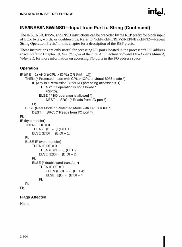
INSTRUCTION SET REFERENCE
peat
ddressl,
INS/INSB/INSW/INSD—Input from Port to String (Continued)
The INS, INSB, INSW, and INSD instructions can be preceded by the REP prefix for block inputof ECX bytes, words, or doublewords. Refer to “REP/REPE/REPZ/REPNE /REPNZ—ReString Operation Prefix” in this chapter for a description of the REP prefix.
These instructions are only useful for accessing I/O ports located in the processor’s I/O aspace. Refer to Chapter 10, Input/Output of the Intel Architecture Software Developer’s ManuaVolume 1, for more information on accessing I/O ports in the I/O address space.
Operation
IF ((PE = 1) AND ((CPL > IOPL) OR (VM = 1)))THEN (* Protected mode with CPL > IOPL or virtual-8086 mode *)
IF (Any I/O Permission Bit for I/O port being accessed = 1)THEN (* I/O operation is not allowed *)
#GP(0);ELSE ( * I/O operation is allowed *)
DEST ← SRC; (* Reads from I/O port *)FI;
ELSE (Real Mode or Protected Mode with CPL ≤ IOPL *)DEST ← SRC; (* Reads from I/O port *)
FI;IF (byte transfer)
THEN IF DF = 0THEN (E)DI ← (E)DI + 1; ELSE (E)DI ← (E)DI – 1;
FI;ELSE IF (word transfer)
THEN IF DF = 0THEN (E)DI ← (E)DI + 2; ELSE (E)DI ← (E)DI – 2;
FI;ELSE (* doubleword transfer *)
THEN IF DF = 0THEN (E)DI ← (E)DI + 4; ELSE (E)DI ← (E)DI – 4;
FI;FI;
FI;
Flags Affected
None.
3-304

INSTRUCTION SET REFERENCE
INS/INSB/INSW/INSD—Input from Port to String (Continued)
Protected Mode Exceptions
#GP(0) If the CPL is greater than (has less privilege) the I/O privilege level (IOPL)and any of the corresponding I/O permission bits in TSS for the I/O portbeing accessed is 1.
If the destination is located in a nonwritable segment.
If an illegal memory operand effective address in the ES segments isgiven.
#PF(fault-code) If a page fault occurs.
#AC(0) If alignment checking is enabled and an unaligned memory reference ismade while the current privilege level is 3.
Real-Address Mode Exceptions
#GP If a memory operand effective address is outside the CS, DS, ES, FS, orGS segment limit.
#SS If a memory operand effective address is outside the SS segment limit.
Virtual-8086 Mode Exceptions
#GP(0) If any of the I/O permission bits in the TSS for the I/O port being accessedis 1.
#PF(fault-code) If a page fault occurs.
#AC(0) If alignment checking is enabled and an unaligned memory reference ismade.
3-305

INSTRUCTION SET REFERENCE
tures.ut this
at return
ReturnsAGS
INT n/INTO/INT 3—Call to Interrupt Procedure
Description
The INT n instruction generates a call to the interrupt or exception handler specified with thedestination operand. For more information, refer to Section 4.4., Interrupts and Exceptions inChapter 4, Procedure Calls, Interrupts, and Exceptions of the Intel Architecture Software Devel-oper’s Manual, Volume 1. The destination operand specifies an interrupt vector number from 0to 255, encoded as an 8-bit unsigned intermediate value. Each interrupt vector number providesan index to a gate descriptor in the IDT. The first 32 interrupt vector numbers are reserved byIntel for system use. Some of these interrupts are used for internally generated exceptions.
The INT n instruction is the general mnemonic for executing a software-generated call to aninterrupt handler. The INTO instruction is a special mnemonic for calling overflow exception(#OF), interrupt vector number 4. The overflow interrupt checks the OF flag in the EFLAGSregister and calls the overflow interrupt handler if the OF flag is set to 1.
The INT 3 instruction generates a special one byte opcode (CC) that is intended for calling thedebug exception handler. (This one byte form is valuable because it can be used to replace thefirst byte of any instruction with a breakpoint, including other one byte instructions, withoutover-writing other code). To further support its function as a debug breakpoint, the interruptgenerated with the CC opcode also differs from the regular software interrupts as follows:
• Interrupt redirection does not happen when in VME mode; the interrupt is handled by aprotected-mode handler.
• The virtual-8086 mode IOPL checks do not occur. The interrupt is taken without faulting atany IOPL level.
Note that the “normal” 2-byte opcode for INT 3 (CD03) does not have these special feaIntel and Microsoft assemblers will not generate the CD03 opcode from any mnemonic, bopcode can be created by direct numeric code definition or by self-modifying code.
The action of the INT n instruction (including the INTO and INT 3 instructions) is similar to thof a far call made with the CALL instruction. The primary difference is that with the INTninstruction, the EFLAGS register is pushed onto the stack before the return address. (Theaddress is a far address consisting of the current values of the CS and EIP registers.) from interrupt procedures are handled with the IRET instruction, which pops the EFLinformation and return address from the stack.
Opcode Instruction Description
CC INT 3 Interrupt 3—trap to debugger
CD ib INT imm8 Interrupt vector number specified by immediate byte
CE INTO Interrupt 4—if overflow flag is 1
3-306

INSTRUCTION SET REFERENCE
kencision #GP).
INT n/INTO/INT 3—Call to Interrupt Procedure (Continued)
The interrupt vector number specifies an interrupt descriptor in the interrupt descriptor table(IDT); that is, it provides index into the IDT. The selected interrupt descriptor in turn contains apointer to an interrupt or exception handler procedure. In protected mode, the IDT containsan array of 8-byte descriptors, each of which is an interrupt gate, trap gate, or task gate. In real-address mode, the IDT is an array of 4-byte far pointers (2-byte code segment selector anda 2-byte instruction pointer), each of which point directly to a procedure in the selected segment.(Note that in real-address mode, the IDT is called the interrupt vector table, and it’s pointersare called interrupt vectors.)
The following decision table indicates which action in the lower portion of the table is tagiven the conditions in the upper portion of the table. Each Y in the lower section of the detable represents a procedure defined in the “Operation” section for this instruction (except
NOTES:
− Don’t Care.
Y Yes, Action Taken.
Blank Action Not Taken.
PE 0 1 1 1 1 1 1 1
VM – – – – – 0 1 1
IOPL – – – – – – <3 =3
DPL/CPL RELATIONSHIP
– DPL<CPL
– DPL>CPL
DPL=CPL or C
DPL<CPL & NC
– –
INTERRUPT TYPE – S/W – – – – – –
GATE TYPE – – Task Trap or Interrupt
Trap or Interrupt
Trap or Interrupt
Trap or Interrupt
Trap or Interrupt
REAL-ADDRESS-MODE
Y
PROTECTED-MODE Y Y Y Y Y Y Y
TRAP-OR-INTERRUPT-GATE
Y Y Y Y Y
INTER-PRIVILEGE-LEVEL-INTERRUPT
Y
INTRA-PRIVILEGE-LEVEL-INTERRUPT
Y
INTERRUPT-FROM-VIRTUAL-8086-MODE
Y
TASK-GATE Y
#GP Y Y Y
3-307

INSTRUCTION SET REFERENCE
INT n/INTO/INT 3—Call to Interrupt Procedure (Continued)
When the processor is executing in virtual-8086 mode, the IOPL determines the action of theINT n instruction. If the IOPL is less than 3, the processor generates a general protection excep-tion (#GP); if the IOPL is 3, the processor executes a protected mode interrupt to privilege level0. The interrupt gate’s DPL must be set to three and the target CPL of the interrupt handler proce-dure must be 0 to execute the protected mode interrupt to privilege level 0.
The interrupt descriptor table register (IDTR) specifies the base linear address and limit of theIDT. The initial base address value of the IDTR after the processor is powered up or reset is 0.
Operation
The following operational description applies not only to the INT n and INTO instructions, butalso to external interrupts and exceptions.
IF PE=0THEN
GOTO REAL-ADDRESS-MODE;ELSE (* PE=1 *)
IF (VM=1 AND IOPL < 3 AND INT n) THEN
#GP(0);ELSE (* protected mode or virtual-8086 mode interrupt *)
GOTO PROTECTED-MODE;FI;
FI;
REAL-ADDRESS-MODE:IF ((DEST ∗ 4) + 3) is not within IDT limit THEN #GP; FI;IF stack not large enough for a 6-byte return information THEN #SS; FI;Push (EFLAGS[15:0]);IF ← 0; (* Clear interrupt flag *)TF ← 0; (* Clear trap flag *)AC ← 0; (*Clear AC flag*)Push(CS);Push(IP);(* No error codes are pushed *)CS ← IDT(Descriptor (vector_number ∗ 4), selector));EIP ← IDT(Descriptor (vector_number ∗ 4), offset)); (* 16-bit offset AND 0000FFFFH *)
END;
PROTECTED-MODE:IF ((DEST ∗ 8) + 7) is not within IDT limits
OR selected IDT descriptor is not an interrupt-, trap-, or task-gate typeTHEN #GP((DEST ∗ 8) + 2 + EXT);(* EXT is bit 0 in error code *)
FI;
3-308
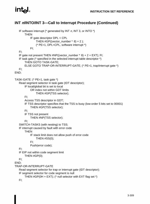
INSTRUCTION SET REFERENCE
INT n/INTO/INT 3—Call to Interrupt Procedure (Continued)
IF software interrupt (* generated by INT n, INT 3, or INTO *)THEN
IF gate descriptor DPL < CPLTHEN #GP((vector_number ∗ 8) + 2 ); (* PE=1, DPL<CPL, software interrupt *)
FI;FI;IF gate not present THEN #NP((vector_number ∗ 8) + 2 + EXT); FI;IF task gate (* specified in the selected interrupt table descriptor *)
THEN GOTO TASK-GATE;ELSE GOTO TRAP-OR-INTERRUPT-GATE; (* PE=1, trap/interrupt gate *)
FI;END;
TASK-GATE: (* PE=1, task gate *)Read segment selector in task gate (IDT descriptor);
IF local/global bit is set to localOR index not within GDT limits
THEN #GP(TSS selector); FI;Access TSS descriptor in GDT;IF TSS descriptor specifies that the TSS is busy (low-order 5 bits set to 00001)
THEN #GP(TSS selector); FI;IF TSS not present
THEN #NP(TSS selector); FI;
SWITCH-TASKS (with nesting) to TSS;IF interrupt caused by fault with error code
THENIF stack limit does not allow push of error code
THEN #SS(0);FI;Push(error code);
FI;IF EIP not within code segment limit
THEN #GP(0); FI;
END;TRAP-OR-INTERRUPT-GATE
Read segment selector for trap or interrupt gate (IDT descriptor);IF segment selector for code segment is null
THEN #GP(0H + EXT); (* null selector with EXT flag set *)FI;
3-309

INSTRUCTION SET REFERENCE
INT n/INTO/INT 3—Call to Interrupt Procedure (Continued)
IF segment selector is not within its descriptor table limits THEN #GP(selector + EXT);
FI;Read trap or interrupt handler descriptor;IF descriptor does not indicate a code segment
OR code segment descriptor DPL > CPLTHEN #GP(selector + EXT);
FI;IF trap or interrupt gate segment is not present,
THEN #NP(selector + EXT);FI;IF code segment is non-conforming AND DPL < CPL
THEN IF VM=0THEN
GOTO INTER-PRIVILEGE-LEVEL-INTERRUPT; (* PE=1, interrupt or trap gate, nonconforming *)(* code segment, DPL<CPL, VM=0 *)
ELSE (* VM=1 *)IF code segment DPL ≠ 0 THEN #GP(new code segment selector); FI;GOTO INTERRUPT-FROM-VIRTUAL-8086-MODE; (* PE=1, interrupt or trap gate, DPL<CPL, VM=1 *)
FI;ELSE (* PE=1, interrupt or trap gate, DPL ≥ CPL *)
IF VM=1 THEN #GP(new code segment selector); FI;IF code segment is conforming OR code segment DPL = CPL
THEN GOTO INTRA-PRIVILEGE-LEVEL-INTERRUPT;
ELSE #GP(CodeSegmentSelector + EXT); (* PE=1, interrupt or trap gate, nonconforming *)(* code segment, DPL>CPL *)
FI;FI;
END;
INTER-PREVILEGE-LEVEL-INTERRUPT(* PE=1, interrupt or trap gate, non-conforming code segment, DPL<CPL *)(* Check segment selector and descriptor for stack of new privilege level in current TSS *)IF current TSS is 32-bit TSS
THEN TSSstackAddress ← (new code segment DPL ∗ 8) + 4IF (TSSstackAddress + 7) > TSS limit
THEN #TS(current TSS selector); FI;NewSS ← TSSstackAddress + 4;NewESP ← stack address;
3-310

INSTRUCTION SET REFERENCE
INT n/INTO/INT 3—Call to Interrupt Procedure (Continued)
ELSE (* TSS is 16-bit *)TSSstackAddress ← (new code segment DPL ∗ 4) + 2IF (TSSstackAddress + 4) > TSS limit
THEN #TS(current TSS selector); FI;NewESP ← TSSstackAddress;NewSS ← TSSstackAddress + 2;
FI;IF segment selector is null THEN #TS(EXT); FI;IF segment selector index is not within its descriptor table limits
OR segment selector’s RPL ≠ DPL of code segment, THEN #TS(SS selector + EXT);
FI;Read segment descriptor for stack segment in GDT or LDT;
IF stack segment DPL ≠ DPL of code segment, OR stack segment does not indicate writable data segment,
THEN #TS(SS selector + EXT);FI;IF stack segment not present THEN #SS(SS selector+EXT); FI;IF 32-bit gate
THENIF new stack does not have room for 24 bytes (error code pushed)
OR 20 bytes (no error code pushed)THEN #SS(segment selector + EXT);
FI;ELSE (* 16-bit gate *)
IF new stack does not have room for 12 bytes (error code pushed) OR 10 bytes (no error code pushed);
THEN #SS(segment selector + EXT); FI;
FI;IF instruction pointer is not within code segment limits THEN #GP(0); FI;SS:ESP ← TSS(NewSS:NewESP) (* segment descriptor information also loaded *)IF 32-bit gate
THEN CS:EIP ← Gate(CS:EIP); (* segment descriptor information also loaded *)
ELSE (* 16-bit gate *)CS:IP ← Gate(CS:IP); (* segment descriptor information also loaded *)
FI;IF 32-bit gate
THENPush(far pointer to old stack); (* old SS and ESP, 3 words padded to 4 *);Push(EFLAGS);Push(far pointer to return instruction); (* old CS and EIP, 3 words padded to 4*);Push(ErrorCode); (* if needed, 4 bytes *)
3-311

INSTRUCTION SET REFERENCE
INT n/INTO/INT 3—Call to Interrupt Procedure (Continued)
ELSE(* 16-bit gate *)Push(far pointer to old stack); (* old SS and SP, 2 words *);Push(EFLAGS(15..0));Push(far pointer to return instruction); (* old CS and IP, 2 words *);Push(ErrorCode); (* if needed, 2 bytes *)
FI;CPL ← CodeSegmentDescriptor(DPL);CS(RPL) ← CPL;IF interrupt gate
THEN IF ← 0 (* interrupt flag to 0 (disabled) *); FI;TF ← 0;VM ← 0;RF ← 0;NT ← 0;END;
INTERRUPT-FROM-VIRTUAL-8086-MODE:(* Check segment selector and descriptor for privilege level 0 stack in current TSS *)IF current TSS is 32-bit TSS
THEN TSSstackAddress ← (new code segment DPL ∗ 8) + 4IF (TSSstackAddress + 7) > TSS limit
THEN #TS(current TSS selector); FI;NewSS ← TSSstackAddress + 4;NewESP ← stack address;
ELSE (* TSS is 16-bit *)TSSstackAddress ← (new code segment DPL ∗ 4) + 2IF (TSSstackAddress + 4) > TSS limit
THEN #TS(current TSS selector); FI;NewESP ← TSSstackAddress;NewSS ← TSSstackAddress + 2;
FI;IF segment selector is null THEN #TS(EXT); FI;IF segment selector index is not within its descriptor table limits
OR segment selector’s RPL ≠ DPL of code segment, THEN #TS(SS selector + EXT);
FI;Access segment descriptor for stack segment in GDT or LDT;IF stack segment DPL ≠ DPL of code segment,
OR stack segment does not indicate writable data segment, THEN #TS(SS selector + EXT);
FI;IF stack segment not present THEN #SS(SS selector+EXT); FI;
3-312
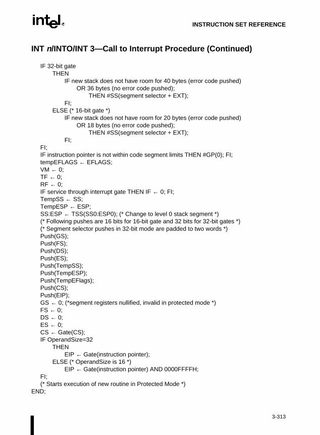
INSTRUCTION SET REFERENCE
INT n/INTO/INT 3—Call to Interrupt Procedure (Continued)
IF 32-bit gateTHEN
IF new stack does not have room for 40 bytes (error code pushed) OR 36 bytes (no error code pushed);
THEN #SS(segment selector + EXT); FI;
ELSE (* 16-bit gate *)IF new stack does not have room for 20 bytes (error code pushed)
OR 18 bytes (no error code pushed);THEN #SS(segment selector + EXT);
FI;FI;IF instruction pointer is not within code segment limits THEN #GP(0); FI;tempEFLAGS ← EFLAGS;VM ← 0;TF ← 0;RF ← 0;IF service through interrupt gate THEN IF ← 0; FI;TempSS ← SS;TempESP ← ESP;SS:ESP ← TSS(SS0:ESP0); (* Change to level 0 stack segment *)(* Following pushes are 16 bits for 16-bit gate and 32 bits for 32-bit gates *)(* Segment selector pushes in 32-bit mode are padded to two words *)Push(GS);Push(FS);Push(DS);Push(ES);Push(TempSS);Push(TempESP);Push(TempEFlags);Push(CS);Push(EIP);GS ← 0; (*segment registers nullified, invalid in protected mode *)FS ← 0;DS ← 0;ES ← 0;CS ← Gate(CS);IF OperandSize=32
THENEIP ← Gate(instruction pointer);
ELSE (* OperandSize is 16 *)EIP ← Gate(instruction pointer) AND 0000FFFFH;
FI;(* Starts execution of new routine in Protected Mode *)
END;
3-313
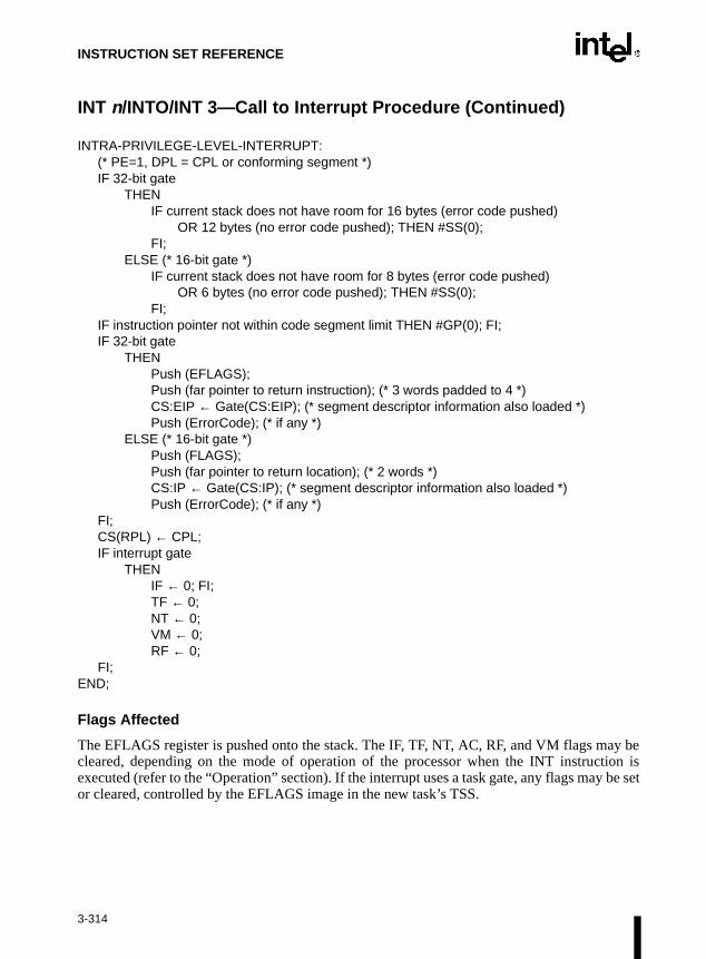
INSTRUCTION SET REFERENCE
be set
INT n/INTO/INT 3—Call to Interrupt Procedure (Continued)
INTRA-PRIVILEGE-LEVEL-INTERRUPT:(* PE=1, DPL = CPL or conforming segment *)IF 32-bit gate
THENIF current stack does not have room for 16 bytes (error code pushed)
OR 12 bytes (no error code pushed); THEN #SS(0);FI;
ELSE (* 16-bit gate *)IF current stack does not have room for 8 bytes (error code pushed)
OR 6 bytes (no error code pushed); THEN #SS(0);FI;
IF instruction pointer not within code segment limit THEN #GP(0); FI;IF 32-bit gate
THENPush (EFLAGS);Push (far pointer to return instruction); (* 3 words padded to 4 *)CS:EIP ← Gate(CS:EIP); (* segment descriptor information also loaded *)Push (ErrorCode); (* if any *)
ELSE (* 16-bit gate *)Push (FLAGS);Push (far pointer to return location); (* 2 words *)CS:IP ← Gate(CS:IP); (* segment descriptor information also loaded *)Push (ErrorCode); (* if any *)
FI;CS(RPL) ← CPL;IF interrupt gate
THENIF ← 0; FI;TF ← 0;NT ← 0;VM ← 0;RF ← 0;
FI;END;
Flags Affected
The EFLAGS register is pushed onto the stack. The IF, TF, NT, AC, RF, and VM flags may becleared, depending on the mode of operation of the processor when the INT instruction isexecuted (refer to the “Operation” section). If the interrupt uses a task gate, any flags mayor cleared, controlled by the EFLAGS image in the new task’s TSS.
3-314
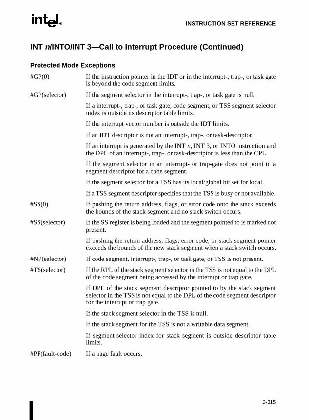
INSTRUCTION SET REFERENCE
INT n/INTO/INT 3—Call to Interrupt Procedure (Continued)
Protected Mode Exceptions
#GP(0) If the instruction pointer in the IDT or in the interrupt-, trap-, or task gateis beyond the code segment limits.
#GP(selector) If the segment selector in the interrupt-, trap-, or task gate is null.
If a interrupt-, trap-, or task gate, code segment, or TSS segment selectorindex is outside its descriptor table limits.
If the interrupt vector number is outside the IDT limits.
If an IDT descriptor is not an interrupt-, trap-, or task-descriptor.
If an interrupt is generated by the INT n, INT 3, or INTO instruction andthe DPL of an interrupt-, trap-, or task-descriptor is less than the CPL.
If the segment selector in an interrupt- or trap-gate does not point to asegment descriptor for a code segment.
If the segment selector for a TSS has its local/global bit set for local.
If a TSS segment descriptor specifies that the TSS is busy or not available.
#SS(0) If pushing the return address, flags, or error code onto the stack exceedsthe bounds of the stack segment and no stack switch occurs.
#SS(selector) If the SS register is being loaded and the segment pointed to is marked notpresent.
If pushing the return address, flags, error code, or stack segment pointerexceeds the bounds of the new stack segment when a stack switch occurs.
#NP(selector) If code segment, interrupt-, trap-, or task gate, or TSS is not present.
#TS(selector) If the RPL of the stack segment selector in the TSS is not equal to the DPLof the code segment being accessed by the interrupt or trap gate.
If DPL of the stack segment descriptor pointed to by the stack segmentselector in the TSS is not equal to the DPL of the code segment descriptorfor the interrupt or trap gate.
If the stack segment selector in the TSS is null.
If the stack segment for the TSS is not a writable data segment.
If segment-selector index for stack segment is outside descriptor tablelimits.
#PF(fault-code) If a page fault occurs.
3-315

INSTRUCTION SET REFERENCE
INT n/INTO/INT 3—Call to Interrupt Procedure (Continued)
Real-Address Mode Exceptions
#GP If a memory operand effective address is outside the CS, DS, ES, FS, orGS segment limit.
If the interrupt vector number is outside the IDT limits.
#SS If stack limit violation on push.
If pushing the return address, flags, or error code onto the stack exceedsthe bounds of the stack segment.
3-316

INSTRUCTION SET REFERENCE
nottrap
able
INT n/INTO/INT 3—Call to Interrupt Procedure (Continued)
Virtual-8086 Mode Exceptions
#GP(0) (For INT n, INTO, or BOUND instruction) If the IOPL is less than 3 or theDPL of the interrupt-, trap-, or task-gate descriptor is not equal to 3.
If the instruction pointer in the IDT or in the interrupt-, trap-, or task gateis beyond the code segment limits.
#GP(selector) If the segment selector in the interrupt-, trap-, or task gate is null.
If a interrupt-, trap-, or task gate, code segment, or TSS segment selectorindex is outside its descriptor table limits.
If the interrupt vector number is outside the IDT limits.
If an IDT descriptor is not an interrupt-, trap-, or task-descriptor.
If an interrupt is generated by the INT n instruction and the DPL of aninterrupt-, trap-, or task-descriptor is less than the CPL.
If the segment selector in an interrupt- or trap-gate does not point to asegment descriptor for a code segment.
If the segment selector for a TSS has its local/global bit set for local.
#SS(selector) If the SS register is being loaded and the segment pointed to is marked notpresent.
If pushing the return address, flags, error code, stack segment pointer, ordata segments exceeds the bounds of the stack segment.
#NP(selector) If code segment, interrupt-, trap-, or task gate, or TSS is not present.
#TS(selector) If the RPL of the stack segment selector in the TSS is not equal to the DPLof the code segment being accessed by the interrupt or trap gate.
If DPL of the stack segment descriptor for the TSS’s stack segment isequal to the DPL of the code segment descriptor for the interrupt or gate.
If the stack segment selector in the TSS is null.
If the stack segment for the TSS is not a writable data segment.
If segment-selector index for stack segment is outside descriptor tlimits.
#PF(fault-code) If a page fault occurs.
#BP If the INT 3 instruction is executed.
#OF If the INTO instruction is executed and the OF flag is set.
3-317

INSTRUCTION SET REFERENCE
l-func-caches
pletety of
cted
y will back main
ntedIntel
INVD—Invalidate Internal Caches
Description
This instruction invalidates (flushes) the processor’s internal caches and issues a speciation bus cycle that directs external caches to also flush themselves. Data held in internal is not written back to main memory.
After executing this instruction, the processor does not wait for the external caches to comtheir flushing operation before proceeding with instruction execution. It is the responsibilihardware to respond to the cache flush signal.
The INVD instruction is a privileged instruction. When the processor is running in protemode, the CPL of a program or procedure must be 0 to execute this instruction.
Use this instruction with care. Data cached internally and not written back to main memorbe lost. Unless there is a specific requirement or benefit to flushing caches without writingmodified cache lines (for example, testing or fault recovery where cache coherency withmemory is not a concern), software should use the WBINVD instruction.
Intel Architecture Compatibility
The INVD instruction is implementation dependent, and its function may be implemedifferently on future Intel Architecture processors. This instruction is not supported on Architecture processors earlier than the Intel486™ processor.
Operation
Flush(InternalCaches);SignalFlush(ExternalCaches);Continue (* Continue execution);
Flags Affected
None.
Protected Mode Exceptions
#GP(0) If the current privilege level is not 0.
Opcode Instruction Description
0F 08 INVD Flush internal caches; initiate flushing of external caches.
3-318
INSTRUCTION SET REFERENCE
INVD—Invalidate Internal Caches (Continued)
Real-Address Mode Exceptions
None.
Virtual-8086 Mode Exceptions
#GP(0) The INVD instruction cannot be executed in virtual-8086 mode.
3-319

INSTRUCTION SET REFERENCE
s” in
ntedIntel
e.
INVLPG—Invalidate TLB Entry
Description
This instruction invalidates (flushes) the translation lookaside buffer (TLB) entry specified withthe source operand. The source operand is a memory address. The processor determines the pagethat contains that address and flushes the TLB entry for that page.
The INVLPG instruction is a privileged instruction. When the processor is running in protectedmode, the CPL of a program or procedure must be 0 to execute this instruction.
The INVLPG instruction normally flushes the TLB entry only for the specified page; however,in some cases, it flushes the entire TLB. Refer to “MOV—Move to/from Control Registerthis chapter for further information on operations that flush the TLB.
Intel Architecture Compatibility
The INVLPG instruction is implementation dependent, and its function may be implemedifferently on future Intel Architecture processors. This instruction is not supported on Architecture processors earlier than the Intel486™ processor.
Operation
Flush(RelevantTLBEntries);Continue (* Continue execution);
Flags Affected
None.
Protected Mode Exceptions
#GP(0) If the current privilege level is not 0.
#UD Operand is a register.
Real-Address Mode Exceptions
#UD Operand is a register.
Virtual-8086 Mode Exceptions
#GP(0) The INVLPG instruction cannot be executed at the virtual-8086 mod
Opcode Instruction Description
0F 01/7 INVLPG m Invalidate TLB Entry for page that contains m
3-320

INSTRUCTION SET REFERENCE
l,
IRET/IRETD—Interrupt Return
Description
These instructions return program control from an exception or interrupt handler to a programor procedure that was interrupted by an exception, an external interrupt, or a software-generatedinterrupt. These instructions are also used to perform a return from a nested task. (A nested taskis created when a CALL instruction is used to initiate a task switch or when an interrupt orexception causes a task switch to an interrupt or exception handler.) Refer to Section 6.4., TaskLinking in Chapter 6, Task Management of the Intel Architecture Software Developer’s ManuaVolume 3.
IRET and IRETD are mnemonics for the same opcode. The IRETD mnemonic (interrupt returndouble) is intended for use when returning from an interrupt when using the 32-bit operand size;however, most assemblers use the IRET mnemonic interchangeably for both operand sizes.
In Real-Address Mode, the IRET instruction preforms a far return to the interrupted program orprocedure. During this operation, the processor pops the return instruction pointer, return codesegment selector, and EFLAGS image from the stack to the EIP, CS, and EFLAGS registers,respectively, and then resumes execution of the interrupted program or procedure.
In Protected Mode, the action of the IRET instruction depends on the settings of the NT (nestedtask) and VM flags in the EFLAGS register and the VM flag in the EFLAGS image stored onthe current stack. Depending on the setting of these flags, the processor performs the followingtypes of interrupt returns:
• Return from virtual-8086 mode.
• Return to virtual-8086 mode.
• Intra-privilege level return.
• Inter-privilege level return.
• Return from nested task (task switch).
If the NT flag (EFLAGS register) is cleared, the IRET instruction performs a far return from theinterrupt procedure, without a task switch. The code segment being returned to must be equallyor less privileged than the interrupt handler routine (as indicated by the RPL field of the codesegment selector popped from the stack). As with a real-address mode interrupt return, the IRETinstruction pops the return instruction pointer, return code segment selector, and EFLAGSimage from the stack to the EIP, CS, and EFLAGS registers, respectively, and then resumesexecution of the interrupted program or procedure. If the return is to another privilege level, theIRET instruction also pops the stack pointer and SS from the stack, before resuming programexecution. If the return is to virtual-8086 mode, the processor also pops the data segment regis-ters from the stack.
Opcode Instruction Description
CF IRET Interrupt return (16-bit operand size)
CF IRETD Interrupt return (32-bit operand size)
3-321
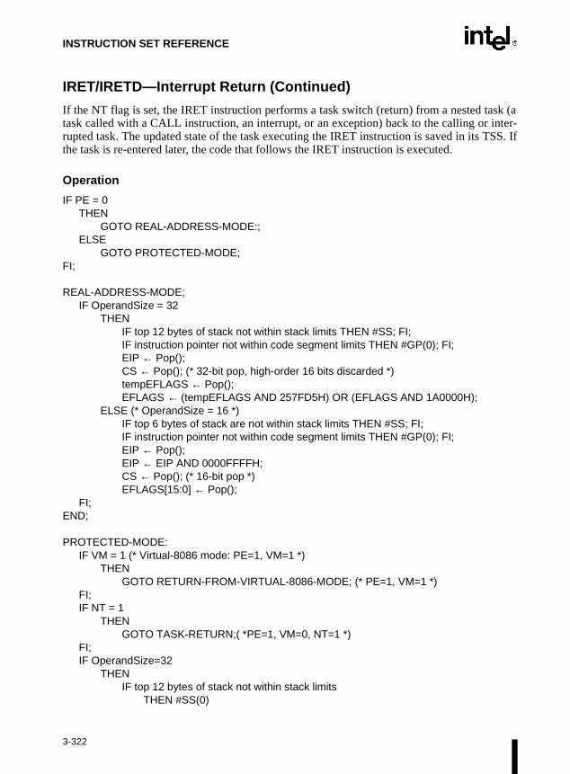
INSTRUCTION SET REFERENCE
IRET/IRETD—Interrupt Return (Continued)
If the NT flag is set, the IRET instruction performs a task switch (return) from a nested task (atask called with a CALL instruction, an interrupt, or an exception) back to the calling or inter-rupted task. The updated state of the task executing the IRET instruction is saved in its TSS. Ifthe task is re-entered later, the code that follows the IRET instruction is executed.
Operation
IF PE = 0THEN
GOTO REAL-ADDRESS-MODE:;ELSE
GOTO PROTECTED-MODE;FI;
REAL-ADDRESS-MODE;IF OperandSize = 32
THENIF top 12 bytes of stack not within stack limits THEN #SS; FI;IF instruction pointer not within code segment limits THEN #GP(0); FI;EIP ← Pop();CS ← Pop(); (* 32-bit pop, high-order 16 bits discarded *)tempEFLAGS ← Pop();EFLAGS ← (tempEFLAGS AND 257FD5H) OR (EFLAGS AND 1A0000H);
ELSE (* OperandSize = 16 *)IF top 6 bytes of stack are not within stack limits THEN #SS; FI;IF instruction pointer not within code segment limits THEN #GP(0); FI;EIP ← Pop();EIP ← EIP AND 0000FFFFH;CS ← Pop(); (* 16-bit pop *)EFLAGS[15:0] ← Pop();
FI;END;
PROTECTED-MODE:IF VM = 1 (* Virtual-8086 mode: PE=1, VM=1 *)
THEN GOTO RETURN-FROM-VIRTUAL-8086-MODE; (* PE=1, VM=1 *)
FI;IF NT = 1
THEN GOTO TASK-RETURN;( *PE=1, VM=0, NT=1 *)
FI;IF OperandSize=32
THENIF top 12 bytes of stack not within stack limits
THEN #SS(0)
3-322

INSTRUCTION SET REFERENCE
IRET/IRETD—Interrupt Return (Continued)
FI;tempEIP ← Pop();tempCS ← Pop();tempEFLAGS ← Pop();
ELSE (* OperandSize = 16 *)IF top 6 bytes of stack are not within stack limits
THEN #SS(0);FI;tempEIP ← Pop();tempCS ← Pop();tempEFLAGS ← Pop();tempEIP ← tempEIP AND FFFFH;tempEFLAGS ← tempEFLAGS AND FFFFH;
FI;IF tempEFLAGS(VM) = 1 AND CPL=0
THEN GOTO RETURN-TO-VIRTUAL-8086-MODE; (* PE=1, VM=1 in EFLAGS image *)
ELSE GOTO PROTECTED-MODE-RETURN;(* PE=1, VM=0 in EFLAGS image *)
FI;
RETURN-FROM-VIRTUAL-8086-MODE: (* Processor is in virtual-8086 mode when IRET is executed and stays in virtual-8086 mode *)
IF IOPL=3 (* Virtual mode: PE=1, VM=1, IOPL=3 *)THEN IF OperandSize = 32
THENIF top 12 bytes of stack not within stack limits THEN #SS(0); FI;IF instruction pointer not within code segment limits THEN #GP(0); FI;EIP ← Pop();CS ← Pop(); (* 32-bit pop, high-order 16 bits discarded *)EFLAGS ← Pop();(*VM,IOPL,VIP,and VIF EFLAGS bits are not modified by pop *)
ELSE (* OperandSize = 16 *)IF top 6 bytes of stack are not within stack limits THEN #SS(0); FI;IF instruction pointer not within code segment limits THEN #GP(0); FI;EIP ← Pop();EIP ← EIP AND 0000FFFFH;CS ← Pop(); (* 16-bit pop *)EFLAGS[15:0] ← Pop(); (* IOPL in EFLAGS is not modified by pop *)
FI;ELSE
#GP(0); (* trap to virtual-8086 monitor: PE=1, VM=1, IOPL<3 *)FI;
3-323

INSTRUCTION SET REFERENCE
IRET/IRETD—Interrupt Return (Continued)
END;
RETURN-TO-VIRTUAL-8086-MODE: (* Interrupted procedure was in virtual-8086 mode: PE=1, VM=1 in flags image *)
IF top 24 bytes of stack are not within stack segment limitsTHEN #SS(0);
FI;IF instruction pointer not within code segment limits
THEN #GP(0);FI;CS ← tempCS;EIP ← tempEIP;EFLAGS ← tempEFLAGSTempESP ← Pop();TempSS ← Pop();ES ← Pop(); (* pop 2 words; throw away high-order word *)DS ← Pop(); (* pop 2 words; throw away high-order word *)FS ← Pop(); (* pop 2 words; throw away high-order word *)GS ← Pop(); (* pop 2 words; throw away high-order word *)SS:ESP ← TempSS:TempESP;(* Resume execution in Virtual-8086 mode *)
END;
TASK-RETURN: (* PE=1, VM=0, NT=1 *)Read segment selector in link field of current TSS;IF local/global bit is set to local
OR index not within GDT limitsTHEN #GP(TSS selector);
FI;Access TSS for task specified in link field of current TSS;IF TSS descriptor type is not TSS or if the TSS is marked not busy
THEN #GP(TSS selector); FI;IF TSS not present
THEN #NP(TSS selector); FI;SWITCH-TASKS (without nesting) to TSS specified in link field of current TSS;Mark the task just abandoned as NOT BUSY;IF EIP is not within code segment limit
THEN #GP(0);FI;
END;
PROTECTED-MODE-RETURN: (* PE=1, VM=0 in flags image *)IF return code segment selector is null THEN GP(0); FI;IF return code segment selector addrsses descriptor beyond descriptor table limit
3-324

INSTRUCTION SET REFERENCE
IRET/IRETD—Interrupt Return (Continued)
THEN GP(selector; FI;Read segment descriptor pointed to by the return code segment selectorIF return code segment descriptor is not a code segment THEN #GP(selector); FI;IF return code segment selector RPL < CPL THEN #GP(selector); FI;IF return code segment descriptor is conforming
AND return code segment DPL > return code segment selector RPLTHEN #GP(selector); FI;
IF return code segment descriptor is not present THEN #NP(selector); FI:IF return code segment selector RPL > CPL
THEN GOTO RETURN-OUTER-PRIVILEGE-LEVEL;ELSE GOTO RETURN-TO-SAME-PRIVILEGE-LEVEL
FI;END;
RETURN-TO-SAME-PRIVILEGE-LEVEL: (* PE=1, VM=0 in flags image, RPL=CPL *)IF EIP is not within code segment limits THEN #GP(0); FI;EIP ← tempEIP;CS ← tempCS; (* segment descriptor information also loaded *)EFLAGS (CF, PF, AF, ZF, SF, TF, DF, OF, NT) ← tempEFLAGS;IF OperandSize=32
THENEFLAGS(RF, AC, ID) ← tempEFLAGS;
FI;IF CPL ≤ IOPL
THENEFLAGS(IF) ← tempEFLAGS;
FI;IF CPL = 0
THENEFLAGS(IOPL) ← tempEFLAGS;IF OperandSize=32
THEN EFLAGS(VM, VIF, VIP) ← tempEFLAGS;FI;
FI;END;
RETURN-TO-OUTER-PRIVILGE-LEVEL:IF OperandSize=32
THENIF top 8 bytes on stack are not within limits THEN #SS(0); FI;
ELSE (* OperandSize=16 *)IF top 4 bytes on stack are not within limits THEN #SS(0); FI;
FI;Read return segment selector;IF stack segment selector is null THEN #GP(0); FI;IF return stack segment selector index is not within its descriptor table limits
3-325

INSTRUCTION SET REFERENCE
ask’s
IRET/IRETD—Interrupt Return (Continued)
THEN #GP(SSselector); FI;Read segment descriptor pointed to by return segment selector;IF stack segment selector RPL ≠ RPL of the return code segment selector
IF stack segment selector RPL ≠ RPL of the return code segment selectorOR the stack segment descriptor does not indicate a a writable data segment;OR stack segment DPL ≠ RPL of the return code segment selector
THEN #GP(SS selector); FI;IF stack segment is not present THEN #SS(SS selector); FI;
IF tempEIP is not within code segment limit THEN #GP(0); FI;EIP ← tempEIP;CS ← tempCS;EFLAGS (CF, PF, AF, ZF, SF, TF, DF, OF, NT) ← tempEFLAGS;IF OperandSize=32
THENEFLAGS(RF, AC, ID) ← tempEFLAGS;
FI;IF CPL ≤ IOPL
THENEFLAGS(IF) ← tempEFLAGS;
FI;IF CPL = 0
THENEFLAGS(IOPL) ← tempEFLAGS;IF OperandSize=32
THEN EFLAGS(VM, VIF, VIP) ← tempEFLAGS;FI;
FI;CPL ← RPL of the return code segment selector;FOR each of segment register (ES, FS, GS, and DS)
DO;IF segment register points to data or non-conforming code segmentAND CPL > segment descriptor DPL (* stored in hidden part of segment register *)
THEN (* segment register invalid *)SegmentSelector ← 0; (* null segment selector *)
FI;OD;
END:
Flags Affected
All the flags and fields in the EFLAGS register are potentially modified, depending on the modeof operation of the processor. If performing a return from a nested task to a previous task, theEFLAGS register will be modified according to the EFLAGS image stored in the previous tTSS.
3-326

INSTRUCTION SET REFERENCE
IRET/IRETD—Interrupt Return (Continued)
Protected Mode Exceptions
#GP(0) If the return code or stack segment selector is null.
If the return instruction pointer is not within the return code segment limit.
#GP(selector) If a segment selector index is outside its descriptor table limits.
If the return code segment selector RPL is greater than the CPL.
If the DPL of a conforming-code segment is greater than the return codesegment selector RPL.
If the DPL for a nonconforming-code segment is not equal to the RPL ofthe code segment selector.
If the stack segment descriptor DPL is not equal to the RPL of the returncode segment selector.
If the stack segment is not a writable data segment.
If the stack segment selector RPL is not equal to the RPL of the return codesegment selector.
If the segment descriptor for a code segment does not indicate it is a codesegment.
If the segment selector for a TSS has its local/global bit set for local.
If a TSS segment descriptor specifies that the TSS is busy or not available.
#SS(0) If the top bytes of stack are not within stack limits.
#NP(selector) If the return code or stack segment is not present.
#PF(fault-code) If a page fault occurs.
#AC(0) If an unaligned memory reference occurs when the CPL is 3 and alignmentchecking is enabled.
Real-Address Mode Exceptions
#GP If the return instruction pointer is not within the return code segment limit.
#SS If the top bytes of stack are not within stack limits.
3-327

INSTRUCTION SET REFERENCE
IRET/IRETD—Interrupt Return (Continued)
Virtual-8086 Mode Exceptions
#GP(0) If the return instruction pointer is not within the return code segment limit.
IF IOPL not equal to 3
#PF(fault-code) If a page fault occurs.
#SS(0) If the top bytes of stack are not within stack limits.
#AC(0) If an unaligned memory reference occurs and alignment checking isenabled.
3-328

INSTRUCTION SET REFERENCE
Jcc—Jump if Condition Is Met
Opcode Instruction Description
77 cb JA rel8 Jump short if above (CF=0 and ZF=0)
73 cb JAE rel8 Jump short if above or equal (CF=0)
72 cb JB rel8 Jump short if below (CF=1)
76 cb JBE rel8 Jump short if below or equal (CF=1 or ZF=1)
72 cb JC rel8 Jump short if carry (CF=1)
E3 cb JCXZ rel8 Jump short if CX register is 0
E3 cb JECXZ rel8 Jump short if ECX register is 0
74 cb JE rel8 Jump short if equal (ZF=1)
7F cb JG rel8 Jump short if greater (ZF=0 and SF=OF)
7D cb JGE rel8 Jump short if greater or equal (SF=OF)
7C cb JL rel8 Jump short if less (SF<>OF)
7E cb JLE rel8 Jump short if less or equal (ZF=1 or SF<>OF)
76 cb JNA rel8 Jump short if not above (CF=1 or ZF=1)
72 cb JNAE rel8 Jump short if not above or equal (CF=1)
73 cb JNB rel8 Jump short if not below (CF=0)
77 cb JNBE rel8 Jump short if not below or equal (CF=0 and ZF=0)
73 cb JNC rel8 Jump short if not carry (CF=0)
75 cb JNE rel8 Jump short if not equal (ZF=0)
7E cb JNG rel8 Jump short if not greater (ZF=1 or SF<>OF)
7C cb JNGE rel8 Jump short if not greater or equal (SF<>OF)
7D cb JNL rel8 Jump short if not less (SF=OF)
7F cb JNLE rel8 Jump short if not less or equal (ZF=0 and SF=OF)
71 cb JNO rel8 Jump short if not overflow (OF=0)
7B cb JNP rel8 Jump short if not parity (PF=0)
79 cb JNS rel8 Jump short if not sign (SF=0)
75 cb JNZ rel8 Jump short if not zero (ZF=0)
70 cb JO rel8 Jump short if overflow (OF=1)
7A cb JP rel8 Jump short if parity (PF=1)
7A cb JPE rel8 Jump short if parity even (PF=1)
7B cb JPO rel8 Jump short if parity odd (PF=0)
78 cb JS rel8 Jump short if sign (SF=1)
74 cb JZ rel8 Jump short if zero (ZF = 1)
0F 87 cw/cd JA rel16/32 Jump near if above (CF=0 and ZF=0)
0F 83 cw/cd JAE rel16/32 Jump near if above or equal (CF=0)
0F 82 cw/cd JB rel16/32 Jump near if below (CF=1)
0F 86 cw/cd JBE rel16/32 Jump near if below or equal (CF=1 or ZF=1)
0F 82 cw/cd JC rel16/32 Jump near if carry (CF=1)
3-329

INSTRUCTION SET REFERENCE
Jcc—Jump if Condition Is Met (Continued)
Description
This instruction checks the state of one or more of the status flags in the EFLAGS register (CF,OF, PF, SF, and ZF) and, if the flags are in the specified state (condition), performs a jump to thetarget instruction specified by the destination operand. A condition code (cc) is associated witheach instruction to indicate the condition being tested for. If the condition is not satisfied, thejump is not performed and execution continues with the instruction following the Jcc instruc-tion.
Opcode Instruction Description
0F 84 cw/cd JE rel16/32 Jump near if equal (ZF=1)
0F 8F cw/cd JG rel16/32 Jump near if greater (ZF=0 and SF=OF)
0F 8D cw/cd JGE rel16/32 Jump near if greater or equal (SF=OF)
0F 8C cw/cd JL rel16/32 Jump near if less (SF<>OF)
0F 8E cw/cd JLE rel16/32 Jump near if less or equal (ZF=1 or SF<>OF)
0F 86 cw/cd JNA rel16/32 Jump near if not above (CF=1 or ZF=1)
0F 82 cw/cd JNAE rel16/32 Jump near if not above or equal (CF=1)
0F 83 cw/cd JNB rel16/32 Jump near if not below (CF=0)
0F 87 cw/cd JNBE rel16/32 Jump near if not below or equal (CF=0 and ZF=0)
0F 83 cw/cd JNC rel16/32 Jump near if not carry (CF=0)
0F 85 cw/cd JNE rel16/32 Jump near if not equal (ZF=0)
0F 8E cw/cd JNG rel16/32 Jump near if not greater (ZF=1 or SF<>OF)
0F 8C cw/cd JNGE rel16/32 Jump near if not greater or equal (SF<>OF)
0F 8D cw/cd JNL rel16/32 Jump near if not less (SF=OF)
0F 8F cw/cd JNLE rel16/32 Jump near if not less or equal (ZF=0 and SF=OF)
0F 81 cw/cd JNO rel16/32 Jump near if not overflow (OF=0)
0F 8B cw/cd JNP rel16/32 Jump near if not parity (PF=0)
0F 89 cw/cd JNS rel16/32 Jump near if not sign (SF=0)
0F 85 cw/cd JNZ rel16/32 Jump near if not zero (ZF=0)
0F 80 cw/cd JO rel16/32 Jump near if overflow (OF=1)
0F 8A cw/cd JP rel16/32 Jump near if parity (PF=1)
0F 8A cw/cd JPE rel16/32 Jump near if parity even (PF=1)
0F 8B cw/cd JPO rel16/32 Jump near if parity odd (PF=0)
0F 88 cw/cd JS rel16/32 Jump near if sign (SF=1)
0F 84 cw/cd JZ rel16/32 Jump near if 0 (ZF=1)
3-330

INSTRUCTION SET REFERENCE
upperr size
heers and
ys, twon and 77H.
targetditionmpp is
tctively,Thesetionalr CX
f jump
Jcc—Jump if Condition Is Met (Continued)
The target instruction is specified with a relative offset (a signed offset relative to the currentvalue of the instruction pointer in the EIP register). A relative offset (rel8, rel16, or rel32) isgenerally specified as a label in assembly code, but at the machine code level, it is encoded as asigned, 8-bit or 32-bit immediate value, which is added to the instruction pointer. Instructioncoding is most efficient for offsets of –128 to +127. If the operand-size attribute is 16, the two bytes of the EIP register are cleared to 0s, resulting in a maximum instruction pointeof 16 bits.
The conditions for each Jcc mnemonic are given in the “Description” column of the table on tpreceding page. The terms “less” and “greater” are used for comparisons of signed integthe terms “above” and “below” are used for unsigned integers.
Because a particular state of the status flags can sometimes be interpreted in two wamnemonics are defined for some opcodes. For example, the JA (jump if above) instructiothe JNBE (jump if not below or equal) instruction are alternate mnemonics for the opcode
The Jcc instruction does not support far jumps (jumps to other code segments). When thefor the conditional jump is in a different segment, use the opposite condition from the conbeing tested for the Jcc instruction, and then access the target with an unconditional far ju(JMP instruction) to the other segment. For example, the following conditional far jumillegal:
JZ FARLABEL;
To accomplish this far jump, use the following two instructions:
JNZ BEYOND;JMP FARLABEL;BEYOND:
The JECXZ and JCXZ instructions differs from the other Jcc instructions because they do nocheck the status flags. Instead they check the contents of the ECX and CX registers, respefor 0. Either the CX or ECX register is chosen according to the address-size attribute. instructions are useful at the beginning of a conditional loop that terminates with a condiloop instruction (such as LOOPNE). They prevent entering the loop when the ECX oregister is equal to 0, which would cause the loop to execute 232 or 64K times, respectively,instead of zero times.
All conditional jumps are converted to code fetches of one or two cache lines, regardless oaddress or cacheability.
3-331

INSTRUCTION SET REFERENCE
Jcc—Jump if Condition Is Met (Continued)
Operation
IF conditionTHEN
EIP ← EIP + SignExtend(DEST);IF OperandSize = 16
THEN EIP ← EIP AND 0000FFFFH;
FI;FI;
Flags Affected
None.
Protected Mode Exceptions
#GP(0) If the offset being jumped to is beyond the limits of the CS segment.
Real-Address Mode Exceptions
#GP If the offset being jumped to is beyond the limits of the CS segment or isoutside of the effective address space from 0 to FFFFH. This condition canoccur if 32-address size override prefix is used.
Virtual-8086 Mode Exceptions
#GP(0) If the offset being jumped to is beyond the limits of the CS segment or isoutside of the effective address space from 0 to FFFFH. This condition canoccur if 32-address size override prefix is used.
3-332

INSTRUCTION SET REFERENCE
entmp.
the
codemp.
JMP—Jump
Description
This instruction transfers program control to a different point in the instruction stream withoutrecording return information. The destination (target) operand specifies the address of theinstruction being jumped to. This operand can be an immediate value, a general-purposeregister, or a memory location.
This instruction can be used to execute four different types of jumps:
• Near jump—A jump to an instruction within the current code segment (the segmcurrently pointed to by the CS register), sometimes referred to as an intrasegment ju
• Short jump—A near jump where the jump range is limited to –128 to +127 fromcurrent EIP value.
• Far jump—A jump to an instruction located in a different segment than the current segment but at the same privilege level, sometimes referred to as an intersegment ju
• Task switch—A jump to an instruction located in a different task.
A task switch can only be executed in protected mode. Refer to Chapter 6, Task Management,of the Intel Architecture Software Developer’s Manual, Volume 3, for information onperforming task switches with the JMP instruction.
Near and Short Jumps. When executing a near jump, the processor jumps to the address(within the current code segment) that is specified with the target operand. The target operandspecifies either an absolute offset (that is an offset from the base of the code segment) or a rela-tive offset (a signed displacement relative to the current value of the instruction pointer in theEIP register). A near jump to a relative offset of 8-bits (rel8) is referred to as a short jump. TheCS register is not changed on near and short jumps.
An absolute offset is specified indirectly in a general-purpose register or a memory location(r/m16 or r/m32). The operand-size attribute determines the size of the target operand (16 or 32bits). Absolute offsets are loaded directly into the EIP register. If the operand-size attribute is16, the upper two bytes of the EIP register are cleared to 0s, resulting in a maximum instructionpointer size of 16 bits.
Opcode Instruction Description
EB cb JMP rel8 Jump short, relative, displacement relative to next instruction
E9 cw JMP rel16 Jump near, relative, displacement relative to next instruction
E9 cd JMP rel32 Jump near, relative, displacement relative to next instruction
FF /4 JMP r/m16 Jump near, absolute indirect, address given in r/m16
FF /4 JMP r/m32 Jump near, absolute indirect, address given in r/m32
EA cd JMP ptr16:16 Jump far, absolute, address given in operand
EA cp JMP ptr16:32 Jump far, absolute, address given in operand
FF /5 JMP m16:16 Jump far, absolute indirect, address given in m16:16
FF /5 JMP m16:32 Jump far, absolute indirect, address given in m16:32
3-333

INSTRUCTION SET REFERENCE
JMP—Jump (Continued)
A relative offset (rel8, rel16, or rel32) is generally specified as a label in assembly code, but atthe machine code level, it is encoded as a signed 8-, 16-, or 32-bit immediate value. This valueis added to the value in the EIP register. (Here, the EIP register contains the address of theinstruction following the JMP instruction). When using relative offsets, the opcode (for short vs.near jumps) and the operand-size attribute (for near relative jumps) determines the size of thetarget operand (8, 16, or 32 bits).
Far Jumps in Real-Address or Virtual-8086 Mode. When executing a far jump in real-address or virtual-8086 mode, the processor jumps to the code segment and offset specified withthe target operand. Here the target operand specifies an absolute far address either directly witha pointer (ptr16:16 or ptr16:32) or indirectly with a memory location (m16:16 or m16:32). Withthe pointer method, the segment and address of the called procedure is encoded in the instruc-tion, using a 4-byte (16-bit operand size) or 6-byte (32-bit operand size) far address immediate.With the indirect method, the target operand specifies a memory location that contains a 4-byte(16-bit operand size) or 6-byte (32-bit operand size) far address. The far address is loadeddirectly into the CS and EIP registers. If the operand-size attribute is 16, the upper two bytes ofthe EIP register are cleared to 0s.
Far Jumps in Protected Mode. When the processor is operating in protected mode, the JMPinstruction can be used to perform the following three types of far jumps:
• A far jump to a conforming or non-conforming code segment.
• A far jump through a call gate.
• A task switch.
(The JMP instruction cannot be used to perform interprivilege level far jumps.)
In protected mode, the processor always uses the segment selector part of the far address toaccess the corresponding descriptor in the GDT or LDT. The descriptor type (code segment, callgate, task gate, or TSS) and access rights determine the type of jump to be performed.
If the selected descriptor is for a code segment, a far jump to a code segment at the same privi-lege level is performed. (If the selected code segment is at a different privilege level and the codesegment is non-conforming, a general-protection exception is generated.) A far jump to the sameprivilege level in protected mode is very similar to one carried out in real-address or virtual-8086mode. The target operand specifies an absolute far address either directly with a pointer(ptr16:16 or ptr16:32) or indirectly with a memory location (m16:16 or m16:32). The operand-size attribute determines the size of the offset (16 or 32 bits) in the far address. The new codesegment selector and its descriptor are loaded into CS register, and the offset from the instructionis loaded into the EIP register. Note that a call gate (described in the next paragraph) can also beused to perform far call to a code segment at the same privilege level. Using this mechanismprovides an extra level of indirection and is the preferred method of making jumps between 16-bit and 32-bit code segments.
3-334

INSTRUCTION SET REFERENCE
de and to be
to EIP
inates
th thecuting thetion,
JMP—Jump (Continued)
When executing a far jump through a call gate, the segment selector specified by the targetoperand identifies the call gate. (The offset part of the target operand is ignored.) The processorthen jumps to the code segment specified in the call gate descriptor and begins executing theinstruction at the offset specified in the call gate. No stack switch occurs. Here again, the targetoperand can specify the far address of the call gate either directly with a pointer (ptr16:16 orptr16:32) or indirectly with a memory location (m16:16 or m16:32).
Executing a task switch with the JMP instruction, is somewhat similar to executing a jumpthrough a call gate. Here the target operand specifies the segment selector of the task gate forthe task being switched to (and the offset part of the target operand is ignored). The task gate inturn points to the TSS for the task, which contains the segment selectors for the task’s costack segments. The TSS also contains the EIP value for the next instruction that wasexecuted before the task was suspended. This instruction pointer value is loaded inregister so that the task begins executing again at this next instruction.
The JMP instruction can also specify the segment selector of the TSS directly, which elimthe indirection of the task gate. Refer to Chapter 6, Task Management, of the Intel ArchitectureSoftware Developer’s Manual, Volume 3, for detailed information on the mechanics of a taskswitch.
Note that when you execute at task switch with a JMP instruction, the nested task flag (NT) isnot set in the EFLAGS register and the new TSS’s previous task link field is not loaded wiold task’s TSS selector. A return to the previous task can thus not be carried out by exethe IRET instruction. Switching tasks with the JMP instruction differs in this regard fromCALL instruction which does set the NT flag and save the previous task link informaallowing a return to the calling task with an IRET instruction.
3-335

INSTRUCTION SET REFERENCE
JMP—Jump (Continued)
Operation
IF near jumpTHEN IF near relative jump
THENtempEIP ← EIP + DEST; (* EIP is instruction following JMP instruction*)
ELSE (* near absolute jump *)tempEIP ← DEST;
FI;IF tempEIP is beyond code segment limit THEN #GP(0); FI;IF OperandSize = 32
THEN EIP ← tempEIP;
ELSE (* OperandSize=16 *)EIP ← tempEIP AND 0000FFFFH;
FI;FI:
IF far jump AND (PE = 0 OR (PE = 1 AND VM = 1)) (* real-address or virtual-8086 mode *)THEN
tempEIP ← DEST(offset); (* DEST is ptr16:32 or [m16:32] *)IF tempEIP is beyond code segment limit THEN #GP(0); FI;CS ← DEST(segment selector); (* DEST is ptr16:32 or [m16:32] *)IF OperandSize = 32
THENEIP ← tempEIP; (* DEST is ptr16:32 or [m16:32] *)
ELSE (* OperandSize = 16 *)EIP ← tempEIP AND 0000FFFFH; (* clear upper 16 bits *)
FI;FI;IF far jump AND (PE = 1 AND VM = 0) (* Protected mode, not virtual-8086 mode *)
THENIF effective address in the CS, DS, ES, FS, GS, or SS segment is illegal
OR segment selector in target operand nullTHEN #GP(0);
FI;IF segment selector index not within descriptor table limits
THEN #GP(new selector);FI;Read type and access rights of segment descriptor;IF segment type is not a conforming or nonconforming code segment, call gate,
task gate, or TSS THEN #GP(segment selector); FI;Depending on type and access rights
GO TO CONFORMING-CODE-SEGMENT;GO TO NONCONFORMING-CODE-SEGMENT;
3-336

INSTRUCTION SET REFERENCE
JMP—Jump (Continued)
GO TO CALL-GATE;GO TO TASK-GATE;GO TO TASK-STATE-SEGMENT;
ELSE #GP(segment selector);
FI;
CONFORMING-CODE-SEGMENT:IF DPL > CPL THEN #GP(segment selector); FI;IF segment not present THEN #NP(segment selector); FI;tempEIP ← DEST(offset);IF OperandSize=16
THEN tempEIP ← tempEIP AND 0000FFFFH; FI;IF tempEIP not in code segment limit THEN #GP(0); FI;CS ← DEST(SegmentSelector); (* segment descriptor information also loaded *)CS(RPL) ← CPLEIP ← tempEIP;
END;
NONCONFORMING-CODE-SEGMENT:IF (RPL > CPL) OR (DPL ≠ CPL) THEN #GP(code segment selector); FI;
IF segment not present THEN #NP(segment selector); FI;IF instruction pointer outside code segment limit THEN #GP(0); FI;tempEIP ← DEST(offset);IF OperandSize=16
THEN tempEIP ← tempEIP AND 0000FFFFH; FI;IF tempEIP not in code segment limit THEN #GP(0); FI;CS ← DEST(SegmentSelector); (* segment descriptor information also loaded *)CS(RPL) ← CPLEIP ← tempEIP;
END;
CALL-GATE:IF call gate DPL < CPL
OR call gate DPL < call gate segment-selector RPL THEN #GP(call gate selector); FI;
IF call gate not present THEN #NP(call gate selector); FI;IF call gate code-segment selector is null THEN #GP(0); FI;IF call gate code-segment selector index is outside descriptor table limits
THEN #GP(code segment selector); FI;Read code segment descriptor;
3-337

INSTRUCTION SET REFERENCE
JMP—Jump (Continued)
IF code-segment segment descriptor does not indicate a code segmentOR code-segment segment descriptor is conforming and DPL > CPLOR code-segment segment descriptor is non-conforming and DPL ≠ CPL
THEN #GP(code segment selector); FI;IF code segment is not present THEN #NP(code-segment selector); FI;IF instruction pointer is not within code-segment limit THEN #GP(0); FI;tempEIP ← DEST(offset);IF GateSize=16
THEN tempEIP ← tempEIP AND 0000FFFFH; FI;IF tempEIP not in code segment limit THEN #GP(0); FI;CS ← DEST(SegmentSelector); (* segment descriptor information also loaded *)CS(RPL) ← CPLEIP ← tempEIP;
END;
TASK-GATE:IF task gate DPL < CPL
OR task gate DPL < task gate segment-selector RPL THEN #GP(task gate selector); FI;
IF task gate not present THEN #NP(gate selector); FI;Read the TSS segment selector in the task-gate descriptor;IF TSS segment selector local/global bit is set to local
OR index not within GDT limitsOR TSS descriptor specifies that the TSS is busy
THEN #GP(TSS selector); FI;IF TSS not present THEN #NP(TSS selector); FI;SWITCH-TASKS to TSS;IF EIP not within code segment limit THEN #GP(0); FI;
END;
TASK-STATE-SEGMENT:IF TSS DPL < CPL
OR TSS DPL < TSS segment-selector RPL OR TSS descriptor indicates TSS not available
THEN #GP(TSS selector); FI;IF TSS is not present THEN #NP(TSS selector); FI;SWITCH-TASKS to TSSIF EIP not within code segment limit THEN #GP(0); FI;
END;
Flags Affected
All flags are affected if a task switch occurs; no flags are affected if a task switch does not occur.
3-338

INSTRUCTION SET REFERENCE
ctor
lessment
t is a
s not
able.
it.
ce ising
JMP—Jump (Continued)
Protected Mode Exceptions
#GP(0) If offset in target operand, call gate, or TSS is beyond the code segmentlimits.
If the segment selector in the destination operand, call gate, task gate, orTSS is null.
If a memory operand effective address is outside the CS, DS, ES, FS, orGS segment limit.
If the DS, ES, FS, or GS register is used to access memory and it containsa null segment selector.
#GP(selector) If segment selector index is outside descriptor table limits.
If the segment descriptor pointed to by the segment selector in thedestination operand is not for a conforming-code segment, noncon-forming-code segment, call gate, task gate, or task state segment.
If the DPL for a nonconforming-code segment is not equal to the CPL
(When not using a call gate.) If the RPL for the segment’s segment seleis greater than the CPL.
If the DPL for a conforming-code segment is greater than the CPL.
If the DPL from a call-gate, task-gate, or TSS segment descriptor is than the CPL or than the RPL of the call-gate, task-gate, or TSS’s segselector.
If the segment descriptor for selector in a call gate does not indicate icode segment.
If the segment descriptor for the segment selector in a task gate doeindicate available TSS.
If the segment selector for a TSS has its local/global bit set for local.
If a TSS segment descriptor specifies that the TSS is busy or not avail
#SS(0) If a memory operand effective address is outside the SS segment lim
#NP (selector) If the code segment being accessed is not present.
If call gate, task gate, or TSS not present.
#PF(fault-code) If a page fault occurs.
#AC(0) If alignment checking is enabled and an unaligned memory referenmade while the current privilege level is 3. (Only occurs when fetchtarget from memory.)
3-339

INSTRUCTION SET REFERENCE
JMP—Jump (Continued)
Real-Address Mode Exceptions
#GP If a memory operand effective address is outside the CS, DS, ES, FS, orGS segment limit.
If a memory operand effective address is outside the CS, DS, ES, FS, orGS segment limit.
#SS If a memory operand effective address is outside the SS segment limit.
Virtual-8086 Mode Exceptions
#GP(0) If the target operand is beyond the code segment limits.
If a memory operand effective address is outside the CS, DS, ES, FS, orGS segment limit.
#SS(0) If a memory operand effective address is outside the SS segment limit.
#PF(fault-code) If a page fault occurs.
#AC(0) If alignment checking is enabled and an unaligned memory reference ismade. (Only occurs when fetching target from memory.)
3-340

INSTRUCTION SET REFERENCE
LAHF—Load Status Flags into AH Register
Description
This instruction moves the low byte of the EFLAGS register (which includes status flags SF, ZF,AF, PF, and CF) to the AH register. Reserved bits 1, 3, and 5 of the EFLAGS register are set inthe AH register as shown in the “Operation” section below.
Operation
AH ← EFLAGS(SF:ZF:0:AF:0:PF:1:CF);
Flags Affected
None (that is, the state of the flags in the EFLAGS register is not affected).
Exceptions (All Operating Modes)
None.
Opcode Instruction Description
9F LAHF Load: AH = EFLAGS(SF:ZF:0:AF:0:PF:1:CF)
3-341

INSTRUCTION SET REFERENCE
LAR—Load Access Rights Byte
Description
This instruction loads the access rights from the segment descriptor specified by the secondoperand (source operand) into the first operand (destination operand) and sets the ZF flag in theEFLAGS register. The source operand (which can be a register or a memory location) containsthe segment selector for the segment descriptor being accessed. The destination operand is ageneral-purpose register.
The processor performs access checks as part of the loading process. Once loaded in the desti-nation register, software can perform additional checks on the access rights information.
When the operand size is 32 bits, the access rights for a segment descriptor include the type andDPL fields and the S, P, AVL, D/B, and G flags, all of which are located in the second double-word (bytes 4 through 7) of the segment descriptor. The doubleword is masked by 00FXFF00Hbefore it is loaded into the destination operand. When the operand size is 16 bits, the accessrights include the type and DPL fields. Here, the two lower-order bytes of the doubleword aremasked by FF00H before being loaded into the destination operand.
This instruction performs the following checks before it loads the access rights in the destinationregister:
• Checks that the segment selector is not null.
• Checks that the segment selector points to a descriptor that is within the limits of the GDTor LDT being accessed
• Checks that the descriptor type is valid for this instruction. All code and data segmentdescriptors are valid for (can be accessed with) the LAR instruction. The valid systemsegment and gate descriptor types are given in the following table.
• If the segment is not a conforming code segment, it checks that the specified segmentdescriptor is visible at the CPL (that is, if the CPL and the RPL of the segment selector areless than or equal to the DPL of the segment selector).
If the segment descriptor cannot be accessed or is an invalid type for the instruction, the ZF flagis cleared and no access rights are loaded in the destination operand.
The LAR instruction can only be executed in protected mode.
Opcode Instruction Description
0F 02 /r LAR r16,r/m16 r16 ← r/m16 masked by FF00H
0F 02 /r LAR r32,r/m32 r32 ← r/m32 masked by 00FxFF00H
3-342

INSTRUCTION SET REFERENCE
LAR—Load Access Rights Byte (Continued)
OperationIF SRC(Offset) > descriptor table limit THEN ZF ← 0; FI;Read segment descriptor;IF SegmentDescriptor(Type) ≠ conforming code segment
AND (CPL > DPL) OR (RPL > DPL)OR Segment type is not valid for instruction
THENZF ← 0
ELSEIF OperandSize = 32
THENDEST ← [SRC] AND 00FxFF00H;
ELSE (*OperandSize = 16*)DEST ← [SRC] AND FF00H;
FI;FI;
Type Name Valid
0 Reserved No
1 Available 16-bit TSS Yes
2 LDT Yes
3 Busy 16-bit TSS Yes
4 16-bit call gate Yes
5 16-bit/32-bit task gate Yes
6 16-bit interrupt gate No
7 16-bit trap gate No
8 Reserved No
9 Available 32-bit TSS Yes
A Reserved No
B Busy 32-bit TSS Yes
C 32-bit call gate Yes
D Reserved No
E 32-bit interrupt gate No
F 32-bit trap gate No
3-343

INSTRUCTION SET REFERENCE
LAR—Load Access Rights Byte (Continued)
Flags Affected
The ZF flag is set to 1 if the access rights are loaded successfully; otherwise, it is cleared to 0.
Protected Mode Exceptions
#GP(0) If a memory operand effective address is outside the CS, DS, ES, FS, orGS segment limit.
If the DS, ES, FS, or GS register is used to access memory and it containsa null segment selector.
#SS(0) If a memory operand effective address is outside the SS segment limit.
#PF(fault-code) If a page fault occurs.
#AC(0) If alignment checking is enabled and an unaligned memory reference ismade while the current privilege level is 3. (Only occurs when fetchingtarget from memory.)
Real-Address Mode Exceptions
#UD The LAR instruction is not recognized in real-address mode.
Virtual-8086 Mode Exceptions
#UD The LAR instruction cannot be executed in virtual-8086 mode.
3-344

INSTRUCTION SET REFERENCE
roesxcep-
onlyIMDidualtions
that at
orre-eaning
arestmetic
LDMXCSR—Load Streaming SIMD Extension Control/Status
Description
The MXCSR control/status register is used to enable masked/unmasked exception handling, toset rounding modes, to set flush-to-zero mode, and to view exception status flags. The followingfigure shows the format and encoding of the fields in MXCSR
The default MXCSR value at reset is 0x1f80.
Bits 5-0 indicate whether a Streaming SIMD Extension numerical exception has been detected.They are “sticky” flags, and can be cleared by using the LDMXCSR instruction to write zeto these fields. If an LDMXCSR instruction clears a mask bit and sets the corresponding etion flag bit, an exception will not be immediately generated. The exception will occur upon the next Streaming SIMD Extension to cause this type of exception. Streaming SExtension uses only one exception flag for each exception. There is no provision for indivexception reporting within a packed data type. In situations where multiple identical excepoccur within the same instruction, the associated exception flag is updated and indicatesleast one of these conditions happened. These flags are cleared upon reset.
Bits 12-7 configure numerical exception masking. An exception type is masked if the csponding bit is set, and unmasked if the bit is clear. These enables are set upon reset, mthat all numerical exceptions are masked.
Bits 14-13 encode the rounding-control, which provides for the common round-to-nemode, as well as directed rounding and true chop. Rounding control affects the arithinstructions and certain conversion instructions. The encoding for RC is as follows:
Opcode Instruction Description
0F,AE,/2 LDMXCSR m32 Load Streaming SIMD Extension control/status word from m32.
31-16 15 10 5 0
Rsvd FZ RC RC PM UM OM ZM DM IM Rsvd PE UE OE ZE DE IE
3-345

INSTRUCTION SET REFERENCE
LDMXCSR—Load Streaming SIMD Extension Control/Status (Continued)
The rounding-control is set to round to nearest upon reset.
Bit 15 (FZ) is used to turn on the Flush To Zero mode (bit is set). Turning on the Flush To Zeromode has the following effects during underflow situations:
• zero results are returned with the sign of the true result
• precision and underflow exception flags are set
The IEEE mandated masked response to underflow is to deliver the denormalized result (i.e.,gradual underflow); consequently, the flush to zero mode is not compatible with IEEE Std. 754.It is provided primarily for performance reasons. At the cost of a slight precision loss, fasterexecution can be achieved for applications where underflows are common. Unmasking theunderflow exception takes precedence over Flush To Zero mode. This arrangement means thatan exception handler will be invoked for a Streaming SIMD Extension that generates an under-flow condition while this exception is unmasked, regardless of whether flush to zero is enabled.
The other bits of MXCSR (bits 31-16 and bit 6) are defined as reserved and cleared; attemptingto write a non-zero value to these bits, using either the FXRSTOR or LDMXCSR instructions,will result in a general protection exception.
The linear address corresponds to the address of the least-significant byte of the referencedmemory data.
Operation
MXCSR = m32;
Rounding Mode RC Field Description
Round to nearest (even)
00B Rounded result is the closest to the infinitely precise result. If two values are equally close, the result is the even value (that is, the one with the least-significant bit of zero).
Round down (to minus infinity)
01B Rounded result is close to but no greater than the infi-nitely precise result
Round up (toward positive infinity)
10B Rounded result is close to but no less than the infinitely precise result.
Round toward zero (truncate)
11B Rounded result is close to but no greater in absolute value than the infinitely precise result.
3-346

INSTRUCTION SET REFERENCE
LDMXCSR—Load Streaming SIMD Extension Control/Status (Continued)
C/C++ Compiler Intrinsic Equivalent
_mm_setcsr(unsigned int i)
Sets the control register to the value specified.
Exceptions
General protection fault if reserved bits are loaded with non-zero values.
Numeric Exceptions
None.
Protected Mode Exceptions
#GP(0) For an illegal memory operand effective address in the CS, DS, ES, FS, orGS segments.
#SS(0) For an illegal address in the SS segment.
#PF(fault-code) For a page fault.
#UD If CR0.EM = 1.
#NM If TS bit in CR0 is set. #AC for unaligned memory reference. To enable#AC exceptions, three conditions must be true(CR0.AM is set;EFLAGS.AC is set; current CPL is 3).
#UD If CR4.OSFXSR(bit 9) = 0.
#UD If CPUID.XMM(EDX bit 25) = 0.
Real Address Mode Exceptions
Interrupt 13 If any part of the operand would lie outside of the effective address spacefrom 0 to 0FFFFH.
#UD If CR0.EM = 1.
#NM If TS bit in CR0 is set.
#UD If CR4.OSFXSR(bit 9) = 0.
#UD If CPUID.XMM(EDX bit 25) = 0.
3-347

INSTRUCTION SET REFERENCE
LDMXCSR—Load Streaming SIMD Extension Control/Status (Continued)
Virtual 8086 Mode Exceptions
Same exceptions as in Real Address Mode.
#PF(fault-code) For a page fault.
#AC For unaligned memory reference.
Comments
The usage of Repeat Prefix (F3H) with LDMXCSR is reserved. Different processor implemen-tations may handle this prefix differently. Usage of this prefix with LDMXCSR risks incompat-ibility with future processors.
3-348

INSTRUCTION SET REFERENCE
LDS/LES/LFS/LGS/LSS—Load Far Pointer
Description
These instructions load a far pointer (segment selector and offset) from the second operand(source operand) into a segment register and the first operand (destination operand). The sourceoperand specifies a 48-bit or a 32-bit pointer in memory depending on the current setting of theoperand-size attribute (32 bits or 16 bits, respectively). The instruction opcode and the destina-tion operand specify a segment register/general-purpose register pair. The 16-bit segmentselector from the source operand is loaded into the segment register specified with the opcode(DS, SS, ES, FS, or GS). The 32-bit or 16-bit offset is loaded into the register specified with thedestination operand.
If one of these instructions is executed in protected mode, additional information from thesegment descriptor pointed to by the segment selector in the source operand is loaded in thehidden part of the selected segment register.
Also in protected mode, a null selector (values 0000 through 0003) can be loaded into DS, ES,FS, or GS registers without causing a protection exception. (Any subsequent reference to asegment whose corresponding segment register is loaded with a null selector, causes a general-protection exception (#GP) and no memory reference to the segment occurs.)
Opcode Instruction Description
C5 /r LDS r16,m16:16 Load DS:r16 with far pointer from memory
C5 /r LDS r32,m16:32 Load DS:r32 with far pointer from memory
0F B2 /r LSS r16,m16:16 Load SS:r16 with far pointer from memory
0F B2 /r LSS r32,m16:32 Load SS:r32 with far pointer from memory
C4 /r LES r16,m16:16 Load ES:r16 with far pointer from memory
C4 /r LES r32,m16:32 Load ES:r32 with far pointer from memory
0F B4 /r LFS r16,m16:16 Load FS:r16 with far pointer from memory
0F B4 /r LFS r32,m16:32 Load FS:r32 with far pointer from memory
0F B5 /r LGS r16,m16:16 Load GS:r16 with far pointer from memory
0F B5 /r LGS r32,m16:32 Load GS:r32 with far pointer from memory
3-349

INSTRUCTION SET REFERENCE
LDS/LES/LFS/LGS/LSS—Load Far Pointer (Continued)
Operation
IF Protected ModeTHEN IF SS is loaded
THEN IF SegementSelector = nullTHEN #GP(0);
FI;ELSE IF Segment selector index is not within descriptor table limitsOR Segment selector RPL ≠ CPLOR Access rights indicate nonwritable data segmentOR DPL ≠ CPL
THEN #GP(selector);FI;ELSE IF Segment marked not present
THEN #SS(selector);FI;SS ← SegmentSelector(SRC);SS ← SegmentDescriptor([SRC]);
ELSE IF DS, ES, FS, or GS is loaded with non-null segment selectorTHEN IF Segment selector index is not within descriptor table limitsOR Access rights indicate segment neither data nor readable code segmentOR (Segment is data or nonconforming-code segment
AND both RPL and CPL > DPL)THEN #GP(selector);
FI;ELSE IF Segment marked not present
THEN #NP(selector);FI;SegmentRegister ← SegmentSelector(SRC) AND RPL;SegmentRegister ← SegmentDescriptor([SRC]);
ELSE IF DS, ES, FS or GS is loaded with a null selector:SegmentRegister ← NullSelector;SegmentRegister(DescriptorValidBit) ← 0; (*hidden flag; not accessible by software*)
FI;FI;IF (Real-Address or Virtual-8086 Mode)
THENSegmentRegister ← SegmentSelector(SRC);
FI;DEST ← Offset(SRC);
3-350

INSTRUCTION SET REFERENCE
LDS/LES/LFS/LGS/LSS—Load Far Pointer (Continued)
Flags Affected
None.
Protected Mode Exceptions
#UD If source operand is not a memory location.
#GP(0) If a null selector is loaded into the SS register.
If a memory operand effective address is outside the CS, DS, ES, FS, orGS segment limit.
If the DS, ES, FS, or GS register is used to access memory and it containsa null segment selector.
#GP(selector) If the SS register is being loaded and any of the following is true: thesegment selector index is not within the descriptor table limits, thesegment selector RPL is not equal to CPL, the segment is a nonwritabledata segment, or DPL is not equal to CPL.
If the DS, ES, FS, or GS register is being loaded with a non-null segmentselector and any of the following is true: the segment selector index is notwithin descriptor table limits, the segment is neither a data nor a readablecode segment, or the segment is a data or nonconforming-code segmentand both RPL and CPL are greater than DPL.
#SS(0) If a memory operand effective address is outside the SS segment limit.
#SS(selector) If the SS register is being loaded and the segment is marked not present.
#NP(selector) If DS, ES, FS, or GS register is being loaded with a non-null segmentselector and the segment is marked not present.
#PF(fault-code) If a page fault occurs.
#AC(0) If alignment checking is enabled and an unaligned memory reference ismade while the current privilege level is 3.
Real-Address Mode Exceptions
#GP If a memory operand effective address is outside the CS, DS, ES, FS, orGS segment limit.
#SS If a memory operand effective address is outside the SS segment limit.
#UD If source operand is not a memory location.
3-351

INSTRUCTION SET REFERENCE
LDS/LES/LFS/LGS/LSS—Load Far Pointer (Continued)
Virtual-8086 Mode Exceptions
#UD If source operand is not a memory location.
#GP(0) If a memory operand effective address is outside the CS, DS, ES, FS, orGS segment limit.
#SS(0) If a memory operand effective address is outside the SS segment limit.
#PF(fault-code) If a page fault occurs.
#AC(0) If alignment checking is enabled and an unaligned memory reference ismade.
3-352

INSTRUCTION SET REFERENCE
LEA—Load Effective Address
Description
This instruction computes the effective address of the second operand (the source operand) andstores it in the first operand (destination operand). The source operand is a memory address(offset part) specified with one of the processors addressing modes; the destination operand is ageneral-purpose register. The address-size and operand-size attributes affect the actionperformed by this instruction, as shown in the following table. The operand-size attribute of theinstruction is determined by the chosen register; the address-size attribute is determined by theattribute of the code segment.
Different assemblers may use different algorithms based on the size attribute and symbolicreference of the source operand.
Opcode Instruction Description
8D /r LEA r16,m Store effective address for m in register r16
8D /r LEA r32,m Store effective address for m in register r32
Operand Size Address Size Action Performed
16 16 16-bit effective address is calculated and stored in requested 16-bit register destination.
16 32 32-bit effective address is calculated. The lower 16 bits of the address are stored in the requested 16-bit register destination.
32 16 16-bit effective address is calculated. The 16-bit address is zero-extended and stored in the requested 32-bit register destination.
32 32 32-bit effective address is calculated and stored in the requested 32-bit register destination.
3-353

INSTRUCTION SET REFERENCE
LEA—Load Effective Address (Continued)
Operation
IF OperandSize = 16 AND AddressSize = 16THEN
DEST ← EffectiveAddress(SRC); (* 16-bit address *)ELSE IF OperandSize = 16 AND AddressSize = 32
THENtemp ← EffectiveAddress(SRC); (* 32-bit address *)DEST ← temp[0..15]; (* 16-bit address *)
ELSE IF OperandSize = 32 AND AddressSize = 16THEN
temp ← EffectiveAddress(SRC); (* 16-bit address *)DEST ← ZeroExtend(temp); (* 32-bit address *)
ELSE IF OperandSize = 32 AND AddressSize = 32THEN
DEST ← EffectiveAddress(SRC); (* 32-bit address *)FI;
FI;
Flags Affected
None.
Protected Mode Exceptions
#UD If source operand is not a memory location.
Real-Address Mode Exceptions
#UD If source operand is not a memory location.
Virtual-8086 Mode Exceptions
#UD If source operand is not a memory location.
3-354

INSTRUCTION SET REFERENCE
am
l,
LEAVE—High Level Procedure Exit
Description
This instruction releases the stack frame set up by an earlier ENTER instruction. The LEAVEinstruction copies the frame pointer (in the EBP register) into the stack pointer register (ESP),which releases the stack space allocated to the stack frame. The old frame pointer (the framepointer for the calling procedure that was saved by the ENTER instruction) is then popped fromthe stack into the EBP register, restoring the calling procedure’s stack frame.
A RET instruction is commonly executed following a LEAVE instruction to return progrcontrol to the calling procedure.
Refer to Section 4.5., Procedure Calls for Block-Structured Languages in Chapter 4, ProcedureCalls, Interrupts, and Exceptions of the Intel Architecture Software Developer’s ManuaVolume 1, for detailed information on the use of the ENTER and LEAVE instructions.
Operation
IF StackAddressSize = 32THEN
ESP ← EBP;ELSE (* StackAddressSize = 16*)
SP ← BP;FI;IF OperandSize = 32
THENEBP ← Pop();
ELSE (* OperandSize = 16*)BP ← Pop();
FI;
Flags Affected
None.
Opcode Instruction Description
C9 LEAVE Set SP to BP, then pop BP
C9 LEAVE Set ESP to EBP, then pop EBP
3-355

INSTRUCTION SET REFERENCE
LEAVE—High Level Procedure Exit (Continued)
Protected Mode Exceptions
#SS(0) If the EBP register points to a location that is not within the limits of thecurrent stack segment.
#PF(fault-code) If a page fault occurs.
#AC(0) If alignment checking is enabled and an unaligned memory reference ismade while the current privilege level is 3.
Real-Address Mode Exceptions
#GP If the EBP register points to a location outside of the effective addressspace from 0 to 0FFFFH.
Virtual-8086 Mode Exceptions
#GP(0) If the EBP register points to a location outside of the effective addressspace from 0 to 0FFFFH.
#PF(fault-code) If a page fault occurs.
#AC(0) If alignment checking is enabled and an unaligned memory reference ismade.
3-356

INSTRUCTION SET REFERENCE
LES—Load Full Pointer
Refer to entry for LDS/LES/LFS/LGS/LSS—Load Far Pointer.
3-357

INSTRUCTION SET REFERENCE
LFS—Load Full Pointer
Refer to entry for LDS/LES/LFS/LGS/LSS—Load Far Pointer.
3-358
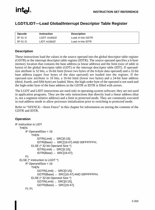
INSTRUCTION SET REFERENCE
f the
LGDT/LIDT—Load Global/Interrupt Descriptor Table Register
Description
These instructions load the values in the source operand into the global descriptor table register(GDTR) or the interrupt descriptor table register (IDTR). The source operand specifies a 6-bytememory location that contains the base address (a linear address) and the limit (size of table inbytes) of the global descriptor table (GDT) or the interrupt descriptor table (IDT). If operand-size attribute is 32 bits, a 16-bit limit (lower two bytes of the 6-byte data operand) and a 32-bitbase address (upper four bytes of the data operand) are loaded into the register. If theoperand-size attribute is 16 bits, a 16-bit limit (lower two bytes) and a 24-bit base address(third, fourth, and fifth byte) are loaded. Here, the high-order byte of the operand is not used andthe high-order byte of the base address in the GDTR or IDTR is filled with zeroes.
The LGDT and LIDT instructions are used only in operating-system software; they are not usedin application programs. They are the only instructions that directly load a linear address (thatis, not a segment-relative address) and a limit in protected mode. They are commonly executedin real-address mode to allow processor initialization prior to switching to protected mode.
Refer to “SFENCE—Store Fence” in this chapter for information on storing the contents oGDTR and IDTR.
Operation
IF instruction is LIDTTHEN
IF OperandSize = 16THEN
IDTR(Limit) ← SRC[0:15];IDTR(Base) ← SRC[16:47] AND 00FFFFFFH;
ELSE (* 32-bit Operand Size *)IDTR(Limit) ← SRC[0:15];IDTR(Base) ← SRC[16:47];
FI;ELSE (* instruction is LGDT *)
IF OperandSize = 16THEN
GDTR(Limit) ← SRC[0:15];GDTR(Base) ← SRC[16:47] AND 00FFFFFFH;
ELSE (* 32-bit Operand Size *)GDTR(Limit) ← SRC[0:15];GDTR(Base) ← SRC[16:47];
FI; FI;
Opcode Instruction Description
0F 01 /2 LGDT m16&32 Load m into GDTR
0F 01 /3 LIDT m16&32 Load m into IDTR
3-359
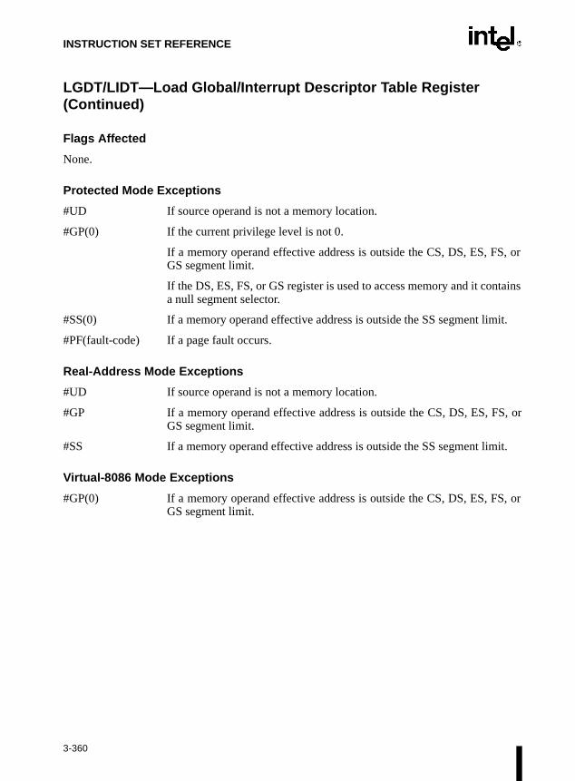
INSTRUCTION SET REFERENCE
LGDT/LIDT—Load Global/Interrupt Descriptor Table Register (Continued)
Flags Affected
None.
Protected Mode Exceptions
#UD If source operand is not a memory location.
#GP(0) If the current privilege level is not 0.
If a memory operand effective address is outside the CS, DS, ES, FS, orGS segment limit.
If the DS, ES, FS, or GS register is used to access memory and it containsa null segment selector.
#SS(0) If a memory operand effective address is outside the SS segment limit.
#PF(fault-code) If a page fault occurs.
Real-Address Mode Exceptions
#UD If source operand is not a memory location.
#GP If a memory operand effective address is outside the CS, DS, ES, FS, orGS segment limit.
#SS If a memory operand effective address is outside the SS segment limit.
Virtual-8086 Mode Exceptions
#GP(0) If a memory operand effective address is outside the CS, DS, ES, FS, orGS segment limit.
3-360

INSTRUCTION SET REFERENCE
LGS—Load Full Pointer
Refer to entry for LDS/LES/LFS/LGS/LSS—Load Far Pointer.
3-361

INSTRUCTION SET REFERENCE
LLDT—Load Local Descriptor Table Register
Description
This instruction loads the source operand into the segment selector field of the local descriptortable register (LDTR). The source operand (a general-purpose register or a memory location)contains a segment selector that points to a local descriptor table (LDT). After the segmentselector is loaded in the LDTR, the processor uses to segment selector to locate the segmentdescriptor for the LDT in the global descriptor table (GDT). It then loads the segment limit andbase address for the LDT from the segment descriptor into the LDTR. The segment registers DS,ES, SS, FS, GS, and CS are not affected by this instruction, nor is the LDTR field in the taskstate segment (TSS) for the current task.
If the source operand is 0, the LDTR is marked invalid and all references to descriptors in theLDT (except by the LAR, VERR, VERW or LSL instructions) cause a general protection excep-tion (#GP).
The operand-size attribute has no effect on this instruction.
The LLDT instruction is provided for use in operating-system software; it should not be used inapplication programs. Also, this instruction can only be executed in protected mode.
OperationIF SRC(Offset) > descriptor table limit THEN #GP(segment selector); FI;Read segment descriptor;IF SegmentDescriptor(Type) ≠ LDT THEN #GP(segment selector); FI;IF segment descriptor is not present THEN #NP(segment selector);LDTR(SegmentSelector) ← SRC;LDTR(SegmentDescriptor) ← GDTSegmentDescriptor;
Flags Affected
None.
Opcode Instruction Description
0F 00 /2 LLDT r/m16 Load segment selector r/m16 into LDTR
3-362
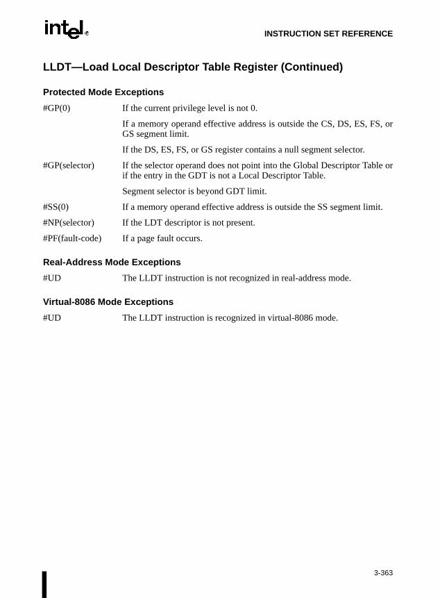
INSTRUCTION SET REFERENCE
LLDT—Load Local Descriptor Table Register (Continued)
Protected Mode Exceptions
#GP(0) If the current privilege level is not 0.
If a memory operand effective address is outside the CS, DS, ES, FS, orGS segment limit.
If the DS, ES, FS, or GS register contains a null segment selector.
#GP(selector) If the selector operand does not point into the Global Descriptor Table orif the entry in the GDT is not a Local Descriptor Table.
Segment selector is beyond GDT limit.
#SS(0) If a memory operand effective address is outside the SS segment limit.
#NP(selector) If the LDT descriptor is not present.
#PF(fault-code) If a page fault occurs.
Real-Address Mode Exceptions
#UD The LLDT instruction is not recognized in real-address mode.
Virtual-8086 Mode Exceptions
#UD The LLDT instruction is recognized in virtual-8086 mode.
3-363

INSTRUCTION SET REFERENCE
LIDT—Load Interrupt Descriptor Table Register
Refer to entry for LGDT/LIDT—Load Global/Interrupt Descriptor Table Register.
3-364
INSTRUCTION SET REFERENCE
se thetionswitch
S, or
tains
it.
LMSW—Load Machine Status Word
Description
This instruction loads the source operand into the machine status word, bits 0 through 15 ofregister CR0. The source operand can be a 16-bit general-purpose register or a memory location.Only the low-order four bits of the source operand (which contains the PE, MP, EM, and TSflags) are loaded into CR0. The PG, CD, NW, AM, WP, NE, and ET flags of CR0 are notaffected. The operand-size attribute has no effect on this instruction.
If the PE flag of the source operand (bit 0) is set to 1, the instruction causes the processor toswitch to protected mode. While in protected mode, the LMSW instruction cannot be used clearthe PE flag and force a switch back to real-address mode.
The LMSW instruction is provided for use in operating-system software; it should not be usedin application programs. In protected or virtual-8086 mode, it can only be executed at CPL 0.
This instruction is provided for compatibility with the Intel 286 processor; programs and proce-dures intended to run on the P6 family, Intel486™, and Intel386™ processors should uMOV (control registers) instruction to load the whole CR0 register. The MOV CR0 instruccan be used to set and clear the PE flag in CR0, allowing a procedure or program to between protected and real-address modes.
This instruction is a serializing instruction.
Operation
CR0[0:3] ← SRC[0:3];
Flags Affected
None.
Protected Mode Exceptions
#GP(0) If the current privilege level is not 0.
If a memory operand effective address is outside the CS, DS, ES, FGS segment limit.
If the DS, ES, FS, or GS register is used to access memory and it cona null segment selector.
#SS(0) If a memory operand effective address is outside the SS segment lim
#PF(fault-code) If a page fault occurs.
Opcode Instruction Description
0F 01 /6 LMSW r/m16 Loads r/m16 in machine status word of CR0
3-365

INSTRUCTION SET REFERENCE
LMSW—Load Machine Status Word (Continued)
Real-Address Mode Exceptions
#GP If a memory operand effective address is outside the CS, DS, ES, FS, orGS segment limit.
Virtual-8086 Mode Exceptions
#GP(0) If the current privilege level is not 0.
If a memory operand effective address is outside the CS, DS, ES, FS, orGS segment limit.
#SS(0) If a memory operand effective address is outside the SS segment limit.
#PF(fault-code) If a page fault occurs.
3-366

INSTRUCTION SET REFERENCE
of thessor
shared
’s cacherds to
LOCK—Assert LOCK# Signal Prefix
Description
This instruction causes the processor’s LOCK# signal to be asserted during execution accompanying instruction (turns the instruction into an atomic instruction). In a multiproceenvironment, the LOCK# signal insures that the processor has exclusive use of any memory while the signal is asserted.
Note that in later Intel Architecture processors (such as the Pentium® Pro processor), lockingmay occur without the LOCK# signal being asserted. Refer to Intel Architecture Compatibilitybelow.
The LOCK prefix can be prepended only to the following instructions and to those forms of theinstructions that use a memory operand: ADD, ADC, AND, BTC, BTR, BTS, CMPXCHG,DEC, INC, NEG, NOT, OR, SBB, SUB, XOR, XADD, and XCHG. An undefined opcodeexception will be generated if the LOCK prefix is used with any other instruction. The XCHGinstruction always asserts the LOCK# signal regardless of the presence or absence of the LOCKprefix.
The LOCK prefix is typically used with the BTS instruction to perform a read-modify-writeoperation on a memory location in shared memory environment.
The integrity of the LOCK prefix is not affected by the alignment of the memory field. Memorylocking is observed for arbitrarily misaligned fields.
Intel Architecture Compatibility
Beginning with the Pentium® Pro processor, when the LOCK prefix is prefixed to an instructionand the memory area being accessed is cached internally in the processor, the LOCK# signal isgenerally not asserted. Instead, only the processor’s cache is locked. Here, the processorcoherency mechanism insures that the operation is carried out atomically with regamemory. Refer to Section 7.1.4., Effects of a LOCK Operation on Internal Processor Caches inChapter 7, Multiple-Processor Management of the Intel Architecture Software Developer’sManual, Volume 3, the for more information on locking of caches.
Operation
AssertLOCK#(DurationOfAccompaningInstruction)
Flags Affected
None.
Opcode Instruction Description
F0 LOCK Asserts LOCK# signal for duration of the accompanying instruction
3-367

INSTRUCTION SET REFERENCE
p-ction
p-ction
p-ction
LOCK—Assert LOCK# Signal Prefix (Continued)
Protected Mode Exceptions
#UD If the LOCK prefix is used with an instruction not listed in the “Descrition” section above. Other exceptions can be generated by the instruthat the LOCK prefix is being applied to.
Real-Address Mode Exceptions
#UD If the LOCK prefix is used with an instruction not listed in the “Descrition” section above. Other exceptions can be generated by the instruthat the LOCK prefix is being applied to.
Virtual-8086 Mode Exceptions
#UD If the LOCK prefix is used with an instruction not listed in the “Descrition” section above. Other exceptions can be generated by the instruthat the LOCK prefix is being applied to.
3-368

INSTRUCTION SET REFERENCE
nds”DSshouldrand isr byteandsy this
rectly
of theAX, ortinationword
AX, to thecre-enteduble-
LODS/LODSB/LODSW/LODSD—Load String
Description
These instructions load a byte, word, or doubleword from the source operand into the AL, AX,or EAX register, respectively. The source operand is a memory location, the address of which isread from the DS:EDI or the DS:SI registers (depending on the address-size attribute of theinstruction, 32 or 16, respectively). The DS segment may be overridden with a segment overrideprefix.
At the assembly-code level, two forms of this instruction are allowed: the “explicit-operaform and the “no-operands” form. The explicit-operands form (specified with the LOmnemonic) allows the source operand to be specified explicitly. Here, the source operand be a symbol that indicates the size and location of the source value. The destination opethen automatically selected to match the size of the source operand (the AL register fooperands, AX for word operands, and EAX for doubleword operands). This explicit-operform is provided to allow documentation; however, note that the documentation provided bform can be misleading. That is, the source operand symbol must specify the correct type (size)of the operand (byte, word, or doubleword), but it does not have to specify the correct location.The location is always specified by the DS:(E)SI registers, which must be loaded corbefore the load string instruction is executed.
The no-operands form provides “short forms” of the byte, word, and doubleword versions LODS instructions. Here also DS:(E)SI is assumed to be the source operand and the AL, EAX register is assumed to be the destination operand. The size of the source and desoperands is selected with the mnemonic: LODSB (byte loaded into register AL), LODSW (loaded into AX), or LODSD (doubleword loaded into EAX).
After the byte, word, or doubleword is transferred from the memory location into the AL, or EAX register, the (E)SI register is incremented or decremented automatically accordingsetting of the DF flag in the EFLAGS register. (If the DF flag is 0, the (E)SI register is inmented; if the DF flag is 1, the ESI register is decremented.) The (E)SI register is incremor decremented by one for byte operations, by two for word operations, or by four for doword operations.
Opcode Instruction Description
AC LODS m8 Load byte at address DS:(E)SI into AL
AD LODS m16 Load word at address DS:(E)SI into AX
AD LODS m32 Load doubleword at address DS:(E)SI into EAX
AC LODSB Load byte at address DS:(E)SI into AL
AD LODSW Load word at address DS:(E)SI into AX
AD LODSD Load doubleword at address DS:(E)SI into EAX
3-369
INSTRUCTION SET REFERENCE
fix.
LODS/LODSB/LODSW/LODSD—Load String (Continued)
The LODS, LODSB, LODSW, and LODSD instructions can be preceded by the REP prefix forblock loads of ECX bytes, words, or doublewords. More often, however, these instructionsare used within a LOOP construct because further processing of the data moved into the registeris usually necessary before the next transfer can be made. Refer to “REP/REPE/REPZ/REPNE/REPNZ—Repeat String Operation Prefix” in this chapter for a description of the REP pre
Operation
IF (byte load)THEN
AL ← SRC; (* byte load *)THEN IF DF = 0
THEN (E)SI ← (E)SI + 1; ELSE (E)SI ← (E)SI – 1;
FI;ELSE IF (word load)
THENAX ← SRC; (* word load *)
THEN IF DF = 0THEN (E)SI ← (E)SI + 2; ELSE (E)SI ← (E)SI – 2;
FI;ELSE (* doubleword transfer *)
EAX ← SRC; (* doubleword load *)THEN IF DF = 0
THEN (E)SI ← (E)SI + 4; ELSE (E)SI ← (E)SI – 4;
FI;FI;
FI;
Flags Affected
None.
Protected Mode Exceptions
#GP(0) If a memory operand effective address is outside the CS, DS, ES, FS, orGS segment limit.
If the DS, ES, FS, or GS register contains a null segment selector.
#SS(0) If a memory operand effective address is outside the SS segment limit.
#PF(fault-code) If a page fault occurs.
#AC(0) If alignment checking is enabled and an unaligned memory reference ismade while the current privilege level is 3.
3-370

INSTRUCTION SET REFERENCE
LODS/LODSB/LODSW/LODSD—Load String (Continued)
Real-Address Mode Exceptions
#GP If a memory operand effective address is outside the CS, DS, ES, FS, orGS segment limit.
#SS If a memory operand effective address is outside the SS segment limit.
Virtual-8086 Mode Exceptions
#GP(0) If a memory operand effective address is outside the CS, DS, ES, FS, orGS segment limit.
#SS(0) If a memory operand effective address is outside the SS segment limit.
#PF(fault-code) If a page fault occurs.
#AC(0) If alignment checking is enabled and an unaligned memory reference ismade.
3-371

INSTRUCTION SET REFERENCE
this
i-dition
e, theother
LOOP/LOOPcc—Loop According to ECX Counter
Description
These instructions perform a loop operation using the ECX or CX register as a counter. Eachtime the LOOP instruction is executed, the count register is decremented, then checked for 0. Ifthe count is 0, the loop is terminated and program execution continues with the instructionfollowing the LOOP instruction. If the count is not zero, a near jump is performed to the desti-nation (target) operand, which is presumably the instruction at the beginning of the loop. If theaddress-size attribute is 32 bits, the ECX register is used as the count register; otherwise the CXregister is used.
The target instruction is specified with a relative offset (a signed offset relative to the currentvalue of the instruction pointer in the EIP register). This offset is generally specified as a labelin assembly code, but at the machine code level, it is encoded as a signed, 8-bit immediate value,which is added to the instruction pointer. Offsets of –128 to +127 are allowed withinstruction.
Some forms of the loop instruction (LOOPcc) also accept the ZF flag as a condition for termnating the loop before the count reaches zero. With these forms of the instruction, a concode (cc) is associated with each instruction to indicate the condition being tested for. HerLOOPcc instruction itself does not affect the state of the ZF flag; the ZF flag is changed by instructions in the loop.
Opcode Instruction Description
E2 cb LOOP rel8 Decrement count; jump short if count ≠ 0
E1 cb LOOPE rel8 Decrement count; jump short if count ≠ 0 and ZF=1
E1 cb LOOPZ rel8 Decrement count; jump short if count ≠ 0 and ZF=1
E0 cb LOOPNE rel8 Decrement count; jump short if count ≠ 0 and ZF=0
E0 cb LOOPNZ rel8 Decrement count; jump short if count ≠ 0 and ZF=0
3-372

INSTRUCTION SET REFERENCE
LOOP/LOOPcc—Loop According to ECX Counter (Continued)
Operation
IF AddressSize = 32THEN
Count is ECX; ELSE (* AddressSize = 16 *)
Count is CX;FI;Count ← Count – 1;
IF instruction is not LOOPTHEN
IF (instruction = LOOPE) OR (instruction = LOOPZ)THEN
IF (ZF =1) AND (Count ≠ 0)THEN BranchCond ← 1;ELSE BranchCond ← 0;
FI;FI;IF (instruction = LOOPNE) OR (instruction = LOOPNZ)
THEN IF (ZF =0 ) AND (Count ≠ 0)
THEN BranchCond ← 1;ELSE BranchCond ← 0;
FI;FI;
ELSE (* instruction = LOOP *)IF (Count ≠ 0)
THEN BranchCond ← 1;ELSE BranchCond ← 0;
FI;FI;IF BranchCond = 1
THEN EIP ← EIP + SignExtend(DEST);
IF OperandSize = 16THEN
EIP ← EIP AND 0000FFFFH;FI;
ELSETerminate loop and continue program execution at EIP;
FI;
3-373

INSTRUCTION SET REFERENCE
LOOP/LOOPcc—Loop According to ECX Counter (Continued)
Flags Affected
None.
Protected Mode Exceptions
#GP(0) If the offset jumped to is beyond the limits of the code segment.
Real-Address Mode Exceptions
None.
Virtual-8086 Mode Exceptions
None.
3-374

INSTRUCTION SET REFERENCE
and
When trun-
esti-
LSL—Load Segment Limit
Description
This instruction loads the unscrambled segment limit from the segment descriptor specified withthe second operand (source operand) into the first operand (destination operand) and sets the ZFflag in the EFLAGS register. The source operand (which can be a register or a memory location)contains the segment selector for the segment descriptor being accessed. The destinationoperand is a general-purpose register.
The processor performs access checks as part of the loading process. Once loaded in the desti-nation register, software can compare the segment limit with the offset of a pointer.
The segment limit is a 20-bit value contained in bytes 0 and 1 and in the first four bits of byte 6of the segment descriptor. If the descriptor has a byte granular segment limit (the granularity flagis set to 0), the destination operand is loaded with a byte granular value (byte limit). If thedescriptor has a page granular segment limit (the granularity flag is set to 1), the LSL instructionwill translate the page granular limit (page limit) into a byte limit before loading it into the desti-nation operand. The translation is performed by shifting the 20-bit “raw” limit left 12 bits filling the low-order 12 bits with 1s.
When the operand size is 32 bits, the 32-bit byte limit is stored in the destination operand.the operand size is 16 bits, a valid 32-bit limit is computed; however, the upper 16 bits arecated and only the low-order 16 bits are loaded into the destination operand.
This instruction performs the following checks before it loads the segment limit into the dnation register:
• Checks that the segment selector is not null.
• Checks that the segment selector points to a descriptor that is within the limits of the GDTor LDT being accessed
• Checks that the descriptor type is valid for this instruction. All code and data segmentdescriptors are valid for (can be accessed with) the LSL instruction. The valid specialsegment and gate descriptor types are given in the following table.
• If the segment is not a conforming code segment, the instruction checks that the specifiedsegment descriptor is visible at the CPL (that is, if the CPL and the RPL of the segmentselector are less than or equal to the DPL of the segment selector).
If the segment descriptor cannot be accessed or is an invalid type for the instruction, the ZF flagis cleared and no value is loaded in the destination operand.
Opcode Instruction Description
0F 03 /r LSL r16,r/m16 Load: r16 ← segment limit, selector r/m16
0F 03 /r LSL r32,r/m32 Load: r32 ← segment limit, selector r/m32)
3-375

INSTRUCTION SET REFERENCE
LSL—Load Segment Limit (Continued)
Type Name Valid
0 Reserved No
1 Available 16-bit TSS Yes
2 LDT Yes
3 Busy 16-bit TSS Yes
4 16-bit call gate No
5 16-bit/32-bit task gate No
6 16-bit interrupt gate No
7 16-bit trap gate No
8 Reserved No
9 Available 32-bit TSS Yes
A Reserved No
B Busy 32-bit TSS Yes
C 32-bit call gate No
D Reserved No
E 32-bit interrupt gate No
F 32-bit trap gate No
3-376

INSTRUCTION SET REFERENCE
LSL—Load Segment Limit (Continued)
OperationIF SRC(Offset) > descriptor table limit
THEN ZF ← 0; FI;Read segment descriptor;IF SegmentDescriptor(Type) ≠ conforming code segment
AND (CPL > DPL) OR (RPL > DPL)OR Segment type is not valid for instruction
THENZF ← 0
ELSEtemp ← SegmentLimit([SRC]);IF (G = 1)
THENtemp ← ShiftLeft(12, temp) OR 00000FFFH;
FI;IF OperandSize = 32
THENDEST ← temp;
ELSE (*OperandSize = 16*)DEST ← temp AND FFFFH;
FI;FI;
Flags Affected
The ZF flag is set to 1 if the segment limit is loaded successfully; otherwise, it is cleared to 0.
Protected Mode Exceptions
#GP(0) If a memory operand effective address is outside the CS, DS, ES, FS, orGS segment limit.
If the DS, ES, FS, or GS register is used to access memory and it containsa null segment selector.
#SS(0) If a memory operand effective address is outside the SS segment limit.
#PF(fault-code) If a page fault occurs.
#AC(0) If alignment checking is enabled and an unaligned memory reference ismade while the current privilege level is 3.
3-377

INSTRUCTION SET REFERENCE
LSL—Load Segment Limit (Continued)
Real-Address Mode Exceptions
#UD The LSL instruction is not recognized in real-address mode.
Virtual-8086 Mode Exceptions
#UD The LSL instruction is not recognized in virtual-8086 mode.
3-378

INSTRUCTION SET REFERENCE
LSS—Load Full Pointer
Refer to entry for LDS/LES/LFS/LGS/LSS—Load Far Pointer.
3-379

INSTRUCTION SET REFERENCE
LTR—Load Task Register
Description
This instruction loads the source operand into the segment selector field of the task register. Thesource operand (a general-purpose register or a memory location) contains a segment selectorthat points to a task state segment (TSS). After the segment selector is loaded in the task register,the processor uses the segment selector to locate the segment descriptor for the TSS in the globaldescriptor table (GDT). It then loads the segment limit and base address for the TSS from thesegment descriptor into the task register. The task pointed to by the task register is marked busy,but a switch to the task does not occur.
The LTR instruction is provided for use in operating-system software; it should not be used inapplication programs. It can only be executed in protected mode when the CPL is 0. It iscommonly used in initialization code to establish the first task to be executed.
The operand-size attribute has no effect on this instruction.
OperationIF SRC(Offset) > descriptor table limit OR IF SRC(type) ≠ global
THEN #GP(segment selector); FI;Read segment descriptor;IF segment descriptor is not for an available TSS THEN #GP(segment selector); FI;IF segment descriptor is not present THEN #NP(segment selector);TSSsegmentDescriptor(busy) ← 1; (* Locked read-modify-write operation on the entire descriptor when setting busy flag *)TaskRegister(SegmentSelector) ← SRC;TaskRegister(SegmentDescriptor) ← TSSSegmentDescriptor;
Flags Affected
None.
Opcode Instruction Description
0F 00 /3 LTR r/m16 Load r/m16 into task register
3-380

INSTRUCTION SET REFERENCE
LTR—Load Task Register (Continued)
Protected Mode Exceptions
#GP(0) If the current privilege level is not 0.
If a memory operand effective address is outside the CS, DS, ES, FS, orGS segment limit.
If the DS, ES, FS, or GS register is used to access memory and it containsa null segment selector.
#GP(selector) If the source selector points to a segment that is not a TSS or to one for atask that is already busy.
If the selector points to LDT or is beyond the GDT limit.
#NP(selector) If the TSS is marked not present.
#SS(0) If a memory operand effective address is outside the SS segment limit.
#PF(fault-code) If a page fault occurs.
Real-Address Mode Exceptions
#UD The LTR instruction is not recognized in real-address mode.
Virtual-8086 Mode Exceptions
#UD The LTR instruction is not recognized in virtual-8086 mode.
3-381

INSTRUCTION SET REFERENCE
gy
MASKMOVQ—Byte Mask Write
Description
Data is stored from the mm1 register to the location specified by the di/edi register (using DSsegment). The size of the store depends on the address-size attribute. The most significant bit ineach byte of the mask register mm2 is used to selectively write the data (0 = no write, 1 = write)on a per-byte basis. Behavior with a mask of all zeroes is as follows:
• No data will be written to memory. However, transition from FP to MMX™ technolostate (if necessary) will occur, irrespective of the value of the mask.
• For memory references, a zero byte mask does not prevent addressing faults (i.e., #GP,#SS) from being signalled.
• Signalling of page faults (#PG) is implementation-specific.
• #UD, #NM, #MF, and #AC faults are signalled irrespective of the value of the mask.
• Signalling of breakpoints (code or data) is not guaranteed; different processor implementa-tions may signal or not signal these breakpoints.
• If the destination memory region is mapped as UC or WP, enforcement of associatedsemantics for these memory types is not guaranteed (i.e., is reserved) and is implemen-tation-specific. Dependence on the behavior of a specific implementation in this case is notrecommended, and may lead to future incompatibility.
The Mod field of the ModR/M byte must be 11, or an Invalid Opcode Exception will result.
Opcode Instruction Description
0F,F7,/r MASKMOVQ mm1, mm2
Move 64-bits representing integer data from MM1 register to memory location specified by the edi register, using the byte mask in MM2 register.
3-382

INSTRUCTION SET REFERENCE
MASKMOVQ—Byte Mask Write (Continued)
Operation
IF (SRC[7] = 1) THENm64[EDI] = DEST[7-0];
ELSEM64[EDI] = 0X0;
IF (SRC[15] = 1) THENm64[EDI] = DEST[15-8];
ELSEM64[EDI] = 0X0;
IF (SRC[23] = 1) THENm64[EDI] = DEST[23-16];
ELSEM64[EDI] = 0X0;
IF (SRC[31] = 1) THENm64[EDI] = DEST[31-24];
ELSEM64[EDI] = 0X0;
IF (SRC[39] = 1) THENm64[EDI] = DEST[39-32];
ELSEM64[EDI] = 0X0;
IF (SRC[47] = 1) THENm64[EDI] = DEST[47-40];
ELSEM64[EDI] = 0X0;
IF (SRC[55] = 1) THENm64[EDI] = DEST[55-48];
ELSEM64[EDI] = 0X0;
IF (SRC[63] = 1) THENm64[EDI] = DEST[63-56];
ELSEM64[EDI] = 0X0;
3-383

INSTRUCTION SET REFERENCE
MASKMOVQ—Byte Mask Write (Continued)
Intel C/C++ Compiler Intrinsic Equivalent
Pre-4.0 Intel C/C++ Compiler intrinsic:
void_m_maskmovq(__m64d, __m64n, char * p)
Version 4.0 and later Intel C/C++ Compiler intrinsic:
void_mm_maskmove_si64(__m64d, __m64n, char * p)
Conditionally store byte elements of d to address p. The high bit of each byte in the selector ndetermines whether the corresponding byte in d will be stored.
Numeric Exceptions
None.
Protected Mode Exceptions
#GP(0) For an illegal memory operand effective address in the CS, DS, ES, FS, orGS segments.
#SS(0) For an illegal address in the SS segment.
#PF (fault-code) For a page fault.
#UD If CR0.EM = 1.
#NM If TS bit in CR0 is set.
#MF If there is a pending FPU exception.
#AC For unaligned memory reference. To enable #AC exceptions, three condi-tions must be true(CR0.AM is set; EFLAGS.AC is set; current CPL is 3)
Real Address Mode Exceptions
Interrupt 13 If any part of the operand would lie outside of the effective address spacefrom 0 to 0FFFFH.
#UD If CR0.EM = 1.
#NM If TS bit in CR0 is set.
#MF If there is a pending FPU exception.
3-384

INSTRUCTION SET REFERENCE
MASKMOVQ—Byte Mask Write (Continued)
Virtual 8086 Mode Exceptions
Same exceptions as in Real Address Mode.
#AC For unaligned memory reference if the current privilege level is 3.
#PF (fault-code) For a page fault.
3-385

INSTRUCTION SET REFERENCE
truc-
ming
MASKMOVQ—Byte Mask Write (Continued)
Comments
MASKMOVQ can be used to improve performance for algorithms which need to merge data ona byte granularity. MASKMOVQ should not cause a read for ownership; doing so generatesunnecessary bandwidth since data is to be written directly using the byte-mask without allo-cating old data prior to the store. Similar to the Streaming SIMD Extension non-temporal storeinstructions, MASKMOVQ minimizes pollution of the cache hierarchy. MASKMOVQ implic-itly uses weakly-ordered, write-combining stores (WC). Refer to Section 9.3.9., CacheabilityControl Instructions in Chapter 9, Programming with the Streaming SIMD Extension of the IntelArchitecture Software Developer’s Manual, Volume 1, for further information about non-temporal stores.
As a consequence of the resulting weakly-ordered memory consistency model, a fencing oper-ation such as SFENCE should be used if multiple processors may use different memory types toread/write the same memory location specified by edi.
This instruction behaves identically to MMX™ instructions, in the presence of x87-FP instions: transition from x87-FP to MMX™ technology (TOS=0, FP valid bits set to all valid).
MASMOVQ ignores the value of CR4.OSFXSR. Since it does not affect the new StreaSIMD Extension state, they will not generate an invalid exception if CR4.OSFXSR = 0.
3-386

INSTRUCTION SET REFERENCE
MAXPS—Packed Single-FP Maximum
Description
The MAXPS instruction returns the maximum SP FP numbers from XMM1 and XMM2/Mem.If the values being compared are both zeroes, source2 (xmm2/m128) would be returned. Ifsource2 (xmm2/m128) is an sNaN, this sNaN is forwarded unchanged to the destination (i.e., aquieted version of the sNaN is not returned).
Figure 3-36. Operation of the MAXPS Instruction
Operation
IF (DEST[31-0]=NaN) THENDEST[31-0] = SRC[31-0];
ELSEIF (SRC[31-0] = NaN) THEN
DEST[31-0] = SRC[31-0];ELSE
IF (DEST[31-0] > SRC/m128[31-0]) THENDEST[31-0] = DEST[31-0];
ELSEDEST[31-0] = SRC/m128[31-0];
FIFI
FI
Opcode Instruction Description
0F,5F,/r MAXPS xmm1, xmm2/m128
Return the maximum SP FP numbers between XMM2/Mem and XMM1.
Xmm1
> > > >Xmm1
Xmm2/m128
99.1 10.99
519.0 8.7
65.0 267.0
519.0
= = = =
3-387

INSTRUCTION SET REFERENCE
MAXPS—Packed Single-FP Maximum (Continued)
IF (DEST[63-32]=NaN) THENDEST[63-32] = SRC[63-32];
ELSEIF (SRC[63-32] = NaN) THEN
DEST[63-32] = SRC[63-32];ELSE
IF (DEST[63-32] > SRC/m128[63-32]) THENDEST[63-32] = DEST[63-32];
ELSEDEST[63-32] = SRC/m128[63-32];
FIFI
FIIF (DEST[95-64]=NaN) THEN
DEST[95-64] = SRC[95-64];ELSE
IF (SRC[95-64] = NaN) THENDEST[95-64] = SRC[95-64];
ELSEIF (DEST[95-64] > SRC/m128[95-64]) THEN
DEST[95-64] = DEST[95-64];ELSE
DEST[95-64] = SRC/m128[95-64];FI
FIFIIF (DEST[127-96]=NaN) THEN
DEST[127-96] = SRC[127-96];ELSE
IF (SRC[127-96] = NaN) THENDEST[127-96] = SRC[127-96];
ELSEIF (DEST[127-96] > SRC/m128[127-96]) THEN
DEST[127-96] = DEST[127-96];ELSE
DEST[127-96] = SRC/m128[127-96];FI
FIFI
3-388

INSTRUCTION SET REFERENCE
MAXPS—Packed Single-FP Maximum (Continued)
Exceptions
General protection exception if not aligned on 16-byte boundary, including unaligned referencewithin the stack segment.
Intel C/C++ Compiler Intrinsic Equivalent
__m128 _mm_max_ps(__m128 a, __m128 b)
Computes the maximums of the four SP FP values of a and b.
Exceptions
General protection exception if not aligned on 16-byte boundary, regardless of segment.
Numeric Exceptions
Invalid (including qNaN source operand), Denormal.
Protected Mode Exceptions
#GP(0) For an illegal memory operand effective address in the CS, DS, ES, FS, orGS segments.
#SS(0) For an illegal address in the SS segment.
#PF(fault-code) For a page fault.
#UD If CR0.EM = 1.
#NM If TS bit in CR0 is set.
#XM For an unmasked Streaming SIMD Extension numeric exception(CR4.OSXMMEXCPT =1).
#UD For an unmasked Streaming SIMD Extension numeric exception(CR4.OSXMMEXCPT =0).
#UD If CR4.OSFXSR(bit 9) = 0.
#UD If CPUID.XMM(EDX bit 25) = 0.
3-389

INSTRUCTION SET REFERENCE
MAXPS—Packed Single-FP Maximum (Continued)
Real Address Mode Exceptions
Interrupt 13 If any part of the operand would lie outside of the effective address spacefrom 0 to 0FFFFH.
#UD If CR0.EM = 1.
#NM If TS bit in CR0 is set.
#XM For an unmasked Streaming SIMD Extension numeric exception(CR4.OSXMMEXCPT =1).
#UD For an unmasked Streaming SIMD Extension numeric exception(CR4.OSXMMEXCPT =0).
#UD If CR4.OSFXSR(bit 9) = 0.
#UD If CPUID.XMM(EDX bit 25) = 0.
Virtual 8086 Mode Exceptions
Same exceptions as in Real Address Mode.
#PF(fault-code) For a page fault.
Comments
Note that if only one source is a NaN for these instructions, the Src2 operand (either NaN or realvalue) is written to the result; this differs from the behavior for other instructions as defined inTable 7-9 in Chapter 7, Floating-Point Unit of the Intel Architecture Software Developer’sManual, Volume 1, which is to always write the NaN to the result, regardless of which sourceoperand contains the NaN. This approach for MAXPS allows compilers to use the MAXPSinstruction for common C conditional constructs. If instead of this behavior, it is required thatthe NaN source operand be returned, the min/max functionality can be emulated using asequence of instructions: comparison followed by AND, ANDN, and OR.
3-390

INSTRUCTION SET REFERENCE
MAXSS—Scalar Single-FP Maximum
Description
The MAXSS instruction returns the maximum SP FP number from the lower SP FP numbers ofXMM1 and XMM2/Mem; the upper three fields are passed through from xmm1. If the valuesbeing compared are both zeroes, source2 (xmm2/m128) will be returned. If source2(xmm2/m128) is an sNaN, this sNaN is forwarded unchanged to the destination (i.e., a quietedversion of the sNaN is not returned).
Figure 3-37. Operation of the MAXSS Instruction
Opcode Instruction Description
F3,0F,5F,/r MAXSS xmm1, xmm2/m32
Return the maximum SP FP number between the lower SP FP numbers from XMM2/Mem and XMM1.
Xmm1
Xmm2/m32
MAXSS xmm1, xmm2/m32
107.3
267.0
>
267.0
Xmm1
=
3-391

INSTRUCTION SET REFERENCE
MAXSS—Scalar Single-FP Maximum (Continued)
Operation
IF (DEST[31-0]=NaN) THENDEST[31-0] = SRC[31-0];
ELSEIF (SRC[31-0] = NaN) THEN
DEST[31-0] = SRC[31-0];ELSE
IF (DEST[31-0] > SRC/m128[31-0]) THENDEST[31-0] = DEST[31-0];
ELSEDEST[31-0] = SRC/m128[31-0];
FIFI
FIDEST[63-32]= DEST[63-32];DEST[95-64]= DEST[95-64];DEST[127-96]= DEST[127-96];
Intel C/C++ Compiler Intrinsic Equivalent
__m128 _mm_max_ss(__m128 a, __m128 b)
Computes the maximum of the lower SP FP values of a and b; the upper three SP FP values arepassed through from a.
Exceptions
None.
Numeric Exceptions
Invalid (including qNaN source operand), Denormal.
3-392

INSTRUCTION SET REFERENCE
MAXSS—Scalar Single-FP Maximum (Continued)
Protected Mode Exceptions
#GP(0) For an illegal memory operand effective address in the CS, DS, ES, FS, orGS segments.
#SS(0) For an illegal address in the SS segment.
#PF (fault-code) For a page fault.
#UD If CR0.EM = 1.
#NM If TS bit in CR0 is set.
#AC For unaligned memory reference. To enable #AC exceptions, three condi-tions must be true(CR0.AM is set; EFLAGS.AC is set; current CPL is 3).
#XM For an unmasked Streaming SIMD Extension numeric exception(CR4.OSXMMEXCPT =1).
#UD For an unmasked Streaming SIMD Extension numeric exception(CR4.OSXMMEXCPT =0).
#UD If CR4.OSFXSR(bit 9) = 0.
#UD If CPUID.XMM(EDX bit 25) = 0.
Real Address Mode Exceptions
Interrupt 13 If any part of the operand would lie outside of the effective address spacefrom 0 to 0FFFFH.
#UD If CR0.EM = 1.
#NM If TS bit in CR0 is set.
#XM For an unmasked Streaming SIMD Extension numeric exception(CR4.OSXMMEXCPT =1).
#UD For an unmasked Streaming SIMD Extension numeric exception(CR4.OSXMMEXCPT =0).
#UD If CR4.OSFXSR(bit 9) = 0.
#UD If CPUID.XMM(EDX bit 25) = 0.
Virtual 8086 Mode Exceptions
Same exceptions as in Real Address Mode.
#AC For unaligned memory reference if the current privilege level is 3.
#PF (fault-code) For a page fault.
3-393

INSTRUCTION SET REFERENCE
MAXSS—Scalar Single-FP Maximum (Continued)
Comments
Note that if only one source is a NaN for these instructions, the Src2 operand (either NaN or realvalue) is written to the result; this differs from the behavior for other instructions as defined inTable 7-9 in Chapter 7, Floating-Point Unit of the Intel Architecture Software Developer’sManual, Volume 1, which is to always write the NaN to the result, regardless of which sourceoperand contains the NaN. The upper three operands are still bypassed from the src1 operand,as in all other scalar operations. This approach for MAXSS allows compilers to use the MAXSSinstruction for common C conditional constructs. If instead of this behavior, it is required thatthe NaN source operand be returned, the min/max functionality can be emulated using asequence of instructions: comparison followed by AND, ANDN, and OR.
3-394

INSTRUCTION SET REFERENCE
MINPS—Packed Single-FP Minimum
Description
The MINPS instruction returns the minimum SP FP numbers from XMM1 and XMM2/Mem. Ifthe values being compared are both zeroes, source2 (xmm2/m128) would be returned. If source2(xmm2/m128) is an sNaN, this sNaN is forwarded unchanged to the destination (i.e., a quietedversion of the sNaN is not returned).
Figure 3-38. Operation of the MINPS Instruction
OperationIF (DEST[31-0]=NaN) THEN
DEST[31-0] = SRC[31-0];ELSE
IF (SRC[31-0] = NaN) THENDEST[31-0] = SRC[31-0];
ELSEIF (DEST[31-0] < SRC/m128[31-0]) THEN
DEST[31-0] = DEST[31-0];ELSE
DEST[31-0] = SRC/m128[31-0];FI
FIFI
Opcode Instruction Description
0F,5D,/r MINPS xmm1, xmm2/m128 Return the minimum SP numbers between XMM2/Mem and XMM1.
Xmm1
Xmm2/m128
MINPS xmm1, xmm2/m128
519.0
99.1
8.7 38.9 107.3
10.99 65.0 267.0
< < < <
38.999.1 8.7 107.3
Xmm1
= ===
3-395

INSTRUCTION SET REFERENCE
MINPS—Packed Single-FP Minimum (Continued)
IF (DEST[63-32]=NaN) THENDEST[63-32] = SRC[63-32];
ELSEIF (SRC[63-32] = NaN) THEN
DEST[63-32] = SRC[63-32];ELSE
IF (DEST[63-32] < SRC/m128[63-32]) THENDEST[63-32] = DEST[63-32];
ELSEDEST[63-32] = SRC/m128[63-32];
FIFI
FIIF (DEST[95-64]=NaN) THEN
DEST[95-64] = SRC[95-64];ELSE
IF (SRC[95-64] = NaN) THENDEST[95-64] = SRC[95-64];
ELSEIF (DEST[95-64] < SRC/m128[95-64]) THEN
DEST[95-64] = DEST[95-64];ELSE
DEST[95-64] = SRC/m128[95-64];FI
FIFIIF (DEST[127-96]=NaN) THEN
DEST[127-96] = SRC[127-96];ELSE
IF (SRC[127-96] = NaN) THENDEST[127-96] = SRC[127-96];
ELSEIF (DEST[127-96] < SRC/m128[127-96]) THEN
DEST[127-96] = DEST[127-96];ELSE
DEST[127-96] = SRC/m128[127-96];FI
FIFI
Intel C/C++ Compiler Intrinsic Equivalent
__m128 _mm_min_ps(__m128 a, __m128 b)
Computes the minimums of the four SP FP values of a and b.
3-396

INSTRUCTION SET REFERENCE
MINPS—Packed Single-FP Minimum (Continued)
Exceptions
General protection exception if not aligned on 16-byte boundary, regardless of segment.
Numeric Exceptions
Invalid (including qNaN source operand), Denormal.
Protected Mode Exceptions
#GP(0) For an illegal memory operand effective address in the CS, DS, ES, FS, orGS segments.
#SS(0) For an illegal address in the SS segment.
#PF(fault-code) For a page fault.
#UD If CR0.EM = 1.
#NM If TS bit in CR0 is set.
#XM For an unmasked Streaming SIMD Extension numeric exception(CR4.OSXMMEXCPT =1).
#UD For an unmasked Streaming SIMD Extension numeric exception(CR4.OSXMMEXCPT =0).
#UD If CR4.OSFXSR(bit 9) = 0.
#UD If CPUID.XMM(EDX bit 25) = 0.
Real Address Mode Exceptions
Interrupt 13 If any part of the operand would lie outside of the effective address spacefrom 0 to 0FFFFH.
#UD If CR0.EM = 1.
#NM If TS bit in CR0 is set.
#XM For an unmasked Streaming SIMD Extension numeric exception(CR4.OSXMMEXCPT =1).
#UD For an unmasked Streaming SIMD Extension numeric exception(CR4.OSXMMEXCPT =0).
#UD If CR4.OSFXSR(bit 9) = 0.
#UD If CPUID.XMM(EDX bit 25) = 0.
3-397

INSTRUCTION SET REFERENCE
MINPS—Packed Single-FP Minimum (Continued)
Virtual 8086 Mode Exceptions
Same exceptions as in Real Address Mode.
#PF(fault-code) For a page fault.
Comments
Note that if only one source is a NaN for these instructions, the Src2 operand (either NaN or realvalue) is written to the result; this differs from the behavior for other instructions as defined inTable 7-9 in Chapter 7, Floating-Point Unit of the Intel Architecture Software Developer’sManual, Volume 1, which is to always write the NaN to the result, regardless of which sourceoperand contains the NaN. This approach for MINPS allows compilers to use the MINPSinstruction for common C conditional constructs. If instead of this behavior, it is required thatthe NaN source operand be returned, the min/max functionality can be emulated using asequence of instructions: comparison followed by AND, ANDN, and OR.
3-398
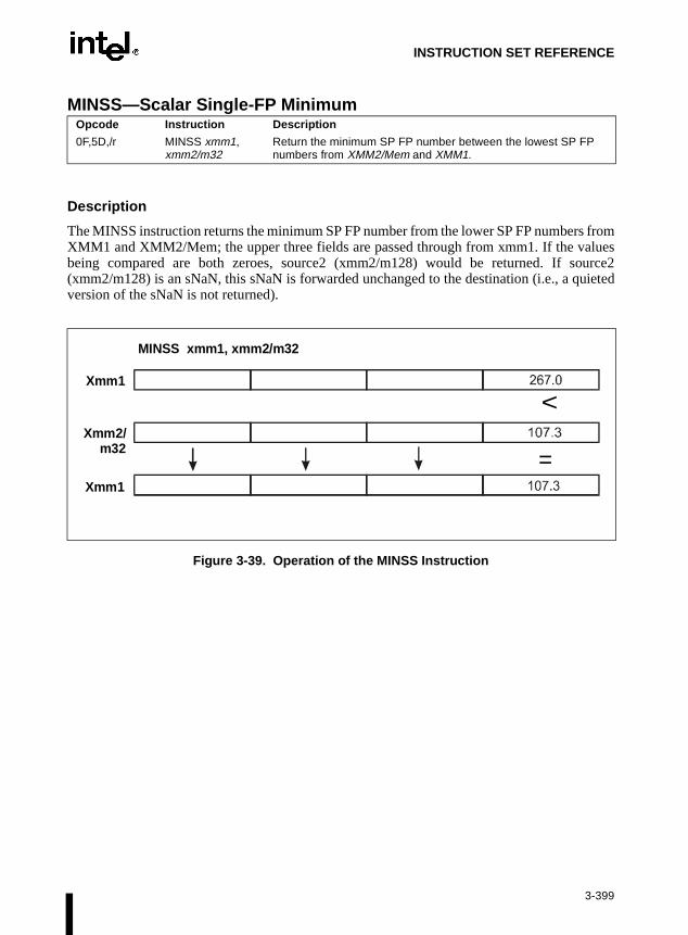
INSTRUCTION SET REFERENCE
MINSS—Scalar Single-FP Minimum
Description
The MINSS instruction returns the minimum SP FP number from the lower SP FP numbers fromXMM1 and XMM2/Mem; the upper three fields are passed through from xmm1. If the valuesbeing compared are both zeroes, source2 (xmm2/m128) would be returned. If source2(xmm2/m128) is an sNaN, this sNaN is forwarded unchanged to the destination (i.e., a quietedversion of the sNaN is not returned).
Figure 3-39. Operation of the MINSS Instruction
Opcode Instruction Description
0F,5D,/r MINSS xmm1, xmm2/m32
Return the minimum SP FP number between the lowest SP FP numbers from XMM2/Mem and XMM1.
=
<Xmm1
Xmm2/m32
Xmm1
MINSS xmm1, xmm2/m32
3-399

INSTRUCTION SET REFERENCE
MINSS—Scalar Single-FP Minimum (Continued)
Operation
IF (DEST[31-0]=NaN) THENDEST[31-0] = SRC[31-0];
ELSEIF (SRC[31-0] = NaN) THEN
DEST[31-0] = SRC[31-0];ELSE
IF (DEST[31-0] < SRC/m128[31-0]) THENDEST[31-0] = DEST[31-0];
ELSEDEST[31-0] = SRC/m128[31-0];
FIFI
FIDEST[63-32]= DEST[63-32];DEST[95-64]= DEST[95-64];DEST[127-96]= DEST[127-96];
Intel C/C++ Compiler Intrinsic Equivalent
__m128 _mm_min_ss(__m128 a, __m128 b)
Computes the minimum of the lower SP FP values of a and b; the upper three SP FP values arepassed through from a.
Exceptions
None.
Numeric Exceptions
Invalid (including qNaN source operand), Denormal.
3-400

INSTRUCTION SET REFERENCE
MINSS—Scalar Single-FP Minimum (Continued)
Protected Mode Exceptions
#GP(0) For an illegal memory operand effective address in the CS, DS, ES, FS, orGS segments.
#SS(0) For an illegal address in the SS segment.
#PF (fault-code) For a page fault.
#UD If CR0.EM = 1.
#NM If TS bit in CR0 is set.
#AC For unaligned memory reference. To enable #AC exceptions, three condi-tions must be true(CR0.AM is set; EFLAGS.AC is set; current CPL is 3).
#XM For an unmasked Streaming SIMD Extension numeric exception(CR4.OSXMMEXCPT =1).
#UD For an unmasked Streaming SIMD Extension numeric exception(CR4.OSXMMEXCPT =0).
#UD If CR4.OSFXSR(bit 9) = 0.
#UD If CPUID.XMM(EDX bit 25) = 0.
Real Address Mode Exceptions
Interrupt 13 If any part of the operand would lie outside of the effective address spacefrom 0 to 0FFFFH.
#UD If CR0.EM = 1.
#NM If TS bit in CR0 is set.
#XM For an unmasked Streaming SIMD Extension numeric exception(CR4.OSXMMEXCPT =1).
#UD For an unmasked Streaming SIMD Extension numeric exception(CR4.OSXMMEXCPT =0).
#UD If CR4.OSFXSR(bit 9) = 0.
#UD If CPUID.XMM(EDX bit 25) = 0.
3-401

INSTRUCTION SET REFERENCE
MINSS—Scalar Single-FP Minimum (Continued)
Virtual 8086 Mode Exceptions
Same exceptions as in Real Address Mode.
#PF (fault-code) For a page fault.
#AC For unaligned memory references.
Comments
Note that if only one source is a NaN for these instructions, the Src2 operand (either NaN or realvalue) is written to the result; this differs from the behavior for other instructions as defined inTable 7-9 in Chapter 7, Floating-Point Unit of the Intel Architecture Software Developer’sManual, Volume 1, which is to always write the NaN to the result, regardless of which sourceoperand contains the NaN. The upper three operands are still bypassed from the src1 operand,as in all other scalar operations. This approach for MINSS allows compilers to use the MINSSinstruction for common C conditional constructs. If instead of this behavior, it is required thatthe NaN source operand be returned, the min/max functionality can be emulated using asequence of instructions: comparison followed by AND, ANDN, and OR.
3-402

INSTRUCTION SET REFERENCE
MOV—Move
NOTES:
* The moffs8, moffs16, and moffs32 operands specify a simple offset relative to the segment base, where8, 16, and 32 refer to the size of the data. The address-size attribute of the instruction determines the sizeof the offset, either 16 or 32 bits.
** In 32-bit mode, the assembler may insert the 16-bit operand-size prefix with this instruction (refer to thefollowing “Description” section for further information).
Description
This instruction copies the second operand (source operand) to the first operand (destinationoperand). The source operand can be an immediate value, general-purpose register, segmentregister, or memory location; the destination register can be a general-purpose register, segmentregister, or memory location. Both operands must be the same size, which can be a byte, a word,or a doubleword.
The MOV instruction cannot be used to load the CS register. Attempting to do so results in aninvalid opcode exception (#UD). To load the CS register, use the far JMP, CALL, or RETinstruction.
Opcode Instruction Description
88 /r MOV r/m8,r8 Move r8 to r/m8
89 /r MOV r/m16,r16 Move r16 to r/m16
89 /r MOV r/m32,r32 Move r32 to r/m32
8A /r MOV r8,r/m8 Move r/m8 to r8
8B /r MOV r16,r/m16 Move r/m16 to r16
8B /r MOV r32,r/m32 Move r/m32 to r32
8C /r MOV r/m16,Sreg** Move segment register to r/m16
8E /r MOV Sreg,r/m16** Move r/m16 to segment register
A0 MOV AL,moffs8* Move byte at (seg:offset) to AL
A1 MOV AX,moffs16* Move word at (seg:offset) to AX
A1 MOV EAX,moffs32* Move doubleword at (seg:offset) to EAX
A2 MOV moffs8*,AL Move AL to (seg:offset)
A3 MOV moffs16*,AX Move AX to (seg:offset)
A3 MOV moffs32*,EAX Move EAX to (seg:offset)
B0+ rb MOV r8,imm8 Move imm8 to r8
B8+ rw MOV r16,imm16 Move imm16 to r16
B8+ rd MOV r32,imm32 Move imm32 to r32
C6 /0 MOV r/m8,imm8 Move imm8 to r/m8
C7 /0 MOV r/m16,imm16 Move imm16 to r/m16
C7 /0 MOV r/m32,imm32 Move imm32 to r/m32
3-403

INSTRUCTION SET REFERENCE
LDT
gistersnce ageneral
tiongister
eneral-of theblers
heith
66Hter, it
ation or-order
MOV—Move (Continued)
If the destination operand is a segment register (DS, ES, FS, GS, or SS), the source operand mustbe a valid segment selector. In protected mode, moving a segment selector into a segmentregister automatically causes the segment descriptor information associated with that segmentselector to be loaded into the hidden (shadow) part of the segment register. While loading thisinformation, the segment selector and segment descriptor information is validated (refer to the“Operation” algorithm below). The segment descriptor data is obtained from the GDT or entry for the specified segment selector.
A null segment selector (values 0000-0003) can be loaded into the DS, ES, FS, and GS rewithout causing a protection exception. However, any subsequent attempt to referesegment whose corresponding segment register is loaded with a null value causes a protection exception (#GP) and no memory reference occurs.
Loading the SS register with a MOV instruction inhibits all interrupts until after the execuof the next instruction. This operation allows a stack pointer to be loaded into the ESP rewith the next instruction (MOV ESP, stack-pointer value) before an interrupt occurs1. The LSSinstruction offers a more efficient method of loading the SS and ESP registers.
When operating in 32-bit mode and moving data between a segment register and a gpurpose register, the Intel Architecture 32-bit family of processors do not require the use 16-bit operand-size prefix (a byte with the value 66H) with this instruction, but most assemwill insert it if the typical form of the instruction is used (for example, MOV DS, AX). Tprocessor will execute this instruction correctly, but it will usually require an extra clock. Wmost assemblers, using the instruction form MOV DS, EAX will avoid this unneeded prefix. When the processor executes the instruction with a 32-bit general-purpose regisassumes that the 16 least-significant bits of the general-purpose register are the destinsource operand. If the register is a destination operand, the resulting value in the two highbytes of the register is implementation dependent. For the Pentium® Pro processor, the two high-order bytes are filled with zeroes; for earlier 32-bit Intel Architecture processors, the two highorder bytes are undefined.
1. Note that in a sequence of instructions that individually delay interrupts past the following instruction, onlythe first instruction in the sequence is guaranteed to delay the interrupt, but subsequent interrupt-delayinginstructions may not delay the interrupt. Thus, in the following instruction sequence:STIMOV SS, EAXMOV ESP, EBPinterrupts may be recognized before MOV ESP, EBP executes, because STI also delays interrupts forone instruction.
3-404

INSTRUCTION SET REFERENCE
MOV—Move (Continued)
Operation
DEST ← SRC;
Loading a segment register while in protected mode results in special checks and actions, asdescribed in the following listing. These checks are performed on the segment selector and thesegment descriptor it points to.
IF SS is loaded;THEN
IF segment selector is null THEN #GP(0);
FI;IF segment selector index is outside descriptor table limits
OR segment selector’s RPL ≠ CPL OR segment is not a writable data segmentOR DPL ≠ CPL
THEN #GP(selector);FI;IF segment not marked present
THEN #SS(selector);ELSE
SS ← segment selector;SS ← segment descriptor;
FI;FI;IF DS, ES, FS or GS is loaded with non-null selector;THEN
IF segment selector index is outside descriptor table limitsOR segment is not a data or readable code segmentOR ((segment is a data or nonconforming code segment)
AND (both RPL and CPL > DPL))THEN #GP(selector);
IF segment not marked presentTHEN #NP(selector);
ELSESegmentRegister ← segment selector;SegmentRegister ← segment descriptor;
FI;FI;IF DS, ES, FS or GS is loaded with a null selector;
THENSegmentRegister ← segment selector;SegmentRegister ← segment descriptor;
FI;
3-405

INSTRUCTION SET REFERENCE
writ-
inted
inted CPL
it.
ed not
inted
ce is
S, or
it.
MOV—Move (Continued)
Flags Affected
None.
Protected Mode Exceptions
#GP(0) If attempt is made to load SS register with null segment selector.
If the destination operand is in a nonwritable segment.
If a memory operand effective address is outside the CS, DS, ES, FS, orGS segment limit.
If the DS, ES, FS, or GS register contains a null segment selector.
#GP(selector) If segment selector index is outside descriptor table limits.
If the SS register is being loaded and the segment selector’s RPL and thesegment descriptor’s DPL are not equal to the CPL.
If the SS register is being loaded and the segment pointed to is a nonable data segment.
If the DS, ES, FS, or GS register is being loaded and the segment poto is not a data or readable code segment.
If the DS, ES, FS, or GS register is being loaded and the segment poto is a data or nonconforming code segment, but both the RPL and theare greater than the DPL.
#SS(0) If a memory operand effective address is outside the SS segment lim
#SS(selector) If the SS register is being loaded and the segment pointed to is markpresent.
#NP If the DS, ES, FS, or GS register is being loaded and the segment poto is marked not present.
#PF(fault-code) If a page fault occurs.
#AC(0) If alignment checking is enabled and an unaligned memory referenmade while the current privilege level is 3.
#UD If attempt is made to load the CS register.
Real-Address Mode Exceptions
#GP If a memory operand effective address is outside the CS, DS, ES, FGS segment limit.
#SS If a memory operand effective address is outside the SS segment lim
#UD If attempt is made to load the CS register.
3-406

INSTRUCTION SET REFERENCE
MOV—Move (Continued)
Virtual-8086 Mode Exceptions
#GP(0) If a memory operand effective address is outside the CS, DS, ES, FS, orGS segment limit.
#SS(0) If a memory operand effective address is outside the SS segment limit.
#PF(fault-code) If a page fault occurs.
#AC(0) If alignment checking is enabled and an unaligned memory reference ismade.
#UD If attempt is made to load the CS register.
3-407

INSTRUCTION SET REFERENCE
MOV—Move to/from Control Registers
Description
This instruction moves the contents of a control register (CR0, CR2, CR3, or CR4) to a general-purpose register or vice versa. The operand size for these instructions is always 32 bits, regard-less of the operand-size attribute. Refer to Section 2.5., Control Registers in Chapter 2, SystemArchitecture Overview of the Intel Architecture Software Developer’s Manual, Volume 3, for adetailed description of the flags and fields in the control registers.
When loading a control register, a program should not attempt to change any of the reserved bits;that is, always set reserved bits to the value previously read.
At the opcode level, the reg field within the ModR/M byte specifies which of the control regis-ters is loaded or read. The two bits in the mod field are always 11B. The r/m field specifies thegeneral-purpose register loaded or read.
These instructions have the following side effects:
• When writing to control register CR3, all non-global TLB entries are flushed. Refer toSection 3.7., Translation Lookaside Buffers (TLBs) in Chapter 3, Protected-Mode MemoryManagement of the Intel Architecture Software Developer’s Manual, Volume 3, for adetailed description of the flags and fields in the control registers.
Opcode Instruction Description
0F 22 /r MOV CR0,r32 Move r32 to CR0
0F 22 /r MOV CR2,r32 Move r32 to CR2
0F 22 /r MOV CR3,r32 Move r32 to CR3
0F 22 /r MOV CR4,r32 Move r32 to CR4
0F 20 /r MOV r32,CR0 Move CR0 to r32
0F 20 /r MOV r32,CR2 Move CR2 to r32
0F 20 /r MOV r32,CR3 Move CR3 to r32
0F 20 /r MOV r32,CR4 Move CR4 to r32
3-408

INSTRUCTION SET REFERENCE
MOV—Move to/from Control Registers (Continued)
The following side effects are implementation specific for the Pentium® Pro processors. Soft-ware should not depend on this functionality in future Intel Architecture processors:
• When modifying any of the paging flags in the control registers (PE and PG in registerCR0 and PGE, PSE, and PAE in register CR4), all TLB entries are flushed, includingglobal entries.
• If the PG flag is set to 1 and control register CR4 is written to set the PAE flag to 1 (toenable the physical address extension mode), the pointers (PDPTRs) in the page-directorypointers table will be loaded into the processor (into internal, non-architectural registers).
• If the PAE flag is set to 1 and the PG flag set to 1, writing to control register CR3 willcause the PDPTRs to be reloaded into the processor.
• If the PAE flag is set to 1 and control register CR0 is written to set the PG flag, thePDPTRs are reloaded into the processor.
Operation
DEST ← SRC;
Flags Affected
The OF, SF, ZF, AF, PF, and CF flags are undefined.
Protected Mode Exceptions
#GP(0) If the current privilege level is not 0.
If an attempt is made to write invalid bit combinations in CR0 (such assetting the PG flag to 1 when the PE flag is set to 0, or setting the CD flagto 0 when the NE flag is set to 1).
If an attempt is made to write a 1 to any reserved bit in CR4.
If an attempt is made to write reserved bits in the page-directory pointerstable (used in the extended physical addressing mode) when the PAE flagin control register CR4 and the PG flag in control register CR0 are set to 1.
Real-Address Mode Exceptions
#GP If an attempt is made to write a 1 to any reserved bit in CR4.
Virtual-8086 Mode Exceptions
#GP(0) These instructions cannot be executed in virtual-8086 mode.
3-409

INSTRUCTION SET REFERENCE
mode, is set,e CR4
MOV—Move to/from Debug Registers
Description
This instruction moves the contents of a debug register (DR0, DR1, DR2, DR3, DR4, DR5,DR6, or DR7) to a general-purpose register or vice versa. The operand size for these instructionsis always 32 bits, regardless of the operand-size attribute. Refer to Chapter 14, Debugging andPerformance Monitoring of the Intel Architecture Software Developer’s Manual, Volume 3, fora detailed description of the flags and fields in the debug registers.
The instructions must be executed at privilege level 0 or in real-address mode.
When the debug extension (DE) flag in register CR4 is clear, these instructions operate on debugregisters in a manner that is compatible with Intel386™ and Intel486™ processors. In this references to DR4 and DR5 refer to DR6 and DR7, respectively. When the DE set in CR4attempts to reference DR4 and DR5 result in an undefined opcode (#UD) exception. (Thregister was added to the Intel Architecture beginning with the Pentium® processor.)
At the opcode level, the reg field within the ModR/M byte specifies which of the debug registersis loaded or read. The two bits in the mod field are always 11. The r/m field specifies the general-purpose register loaded or read.
Operation
IF ((DE = 1) and (SRC or DEST = DR4 or DR5))THEN
#UD;ELSE
DEST ← SRC;
Flags Affected
The OF, SF, ZF, AF, PF, and CF flags are undefined.
Protected Mode Exceptions
#GP(0) If the current privilege level is not 0.
#UD If the DE (debug extensions) bit of CR4 is set and a MOV instruction isexecuted involving DR4 or DR5.
#DB If any debug register is accessed while the GD flag in debug register DR7is set.
Opcode Instruction Description
0F 21/r MOV r32, DR0-DR7 Move debug register to r32
0F 23 /r MOV DR0-DR7,r32 Move r32 to debug register
3-410

INSTRUCTION SET REFERENCE
MOV—Move to/from Debug Registers (Continued)
Real-Address Mode Exceptions
#UD If the DE (debug extensions) bit of CR4 is set and a MOV instruction isexecuted involving DR4 or DR5.
#DB If any debug register is accessed while the GD flag in debug register DR7is set.
Virtual-8086 Mode Exceptions
#GP(0) The debug registers cannot be loaded or read when in virtual-8086 mode.
3-411
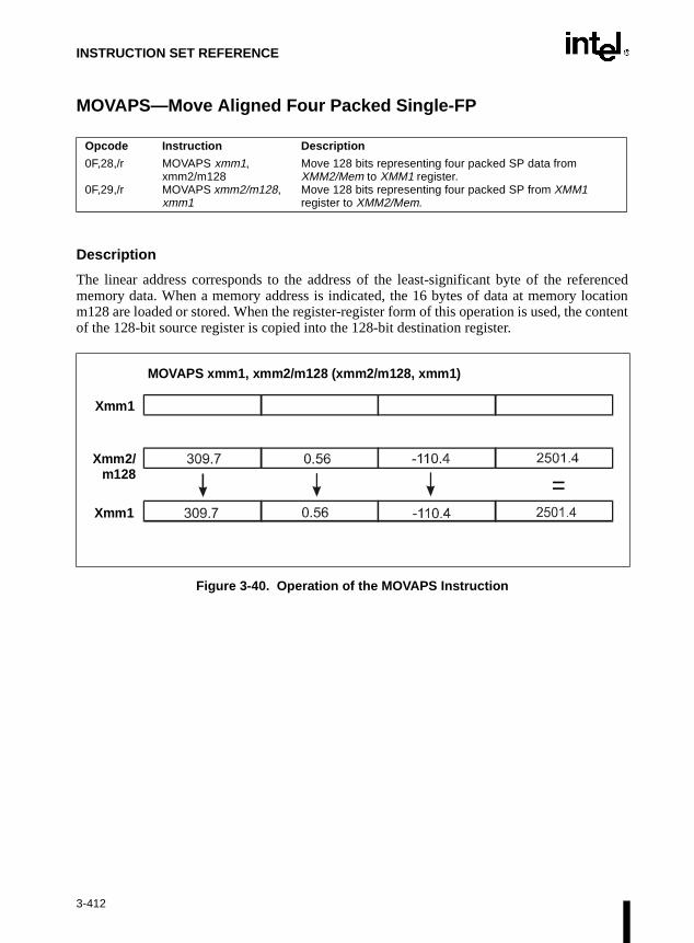
INSTRUCTION SET REFERENCE
MOVAPS—Move Aligned Four Packed Single-FP
Description
The linear address corresponds to the address of the least-significant byte of the referencedmemory data. When a memory address is indicated, the 16 bytes of data at memory locationm128 are loaded or stored. When the register-register form of this operation is used, the contentof the 128-bit source register is copied into the 128-bit destination register.
Figure 3-40. Operation of the MOVAPS Instruction
Opcode Instruction Description
0F,28,/r
0F,29,/r
MOVAPS xmm1, xmm2/m128MOVAPS xmm2/m128, xmm1
Move 128 bits representing four packed SP data from XMM2/Mem to XMM1 register.Move 128 bits representing four packed SP from XMM1 register to XMM2/Mem.
=
Xmm1
Xmm2/m128
Xmm1
MOVAPS xmm1, xmm2/m128 (xmm2/m128, xmm1)
3-412

INSTRUCTION SET REFERENCE
MOVAPS—Move Aligned Four Packed Single-FP (Continued)
Operation
IF (destination = DEST) THENIF (SRC = m128)THEN (* load instruction *)
DEST[127-0] = m128;ELSE(* move instruction *)
DEST[127=0] = SRC[127-0];FI;
ELSEIF (destination = m128)THEN (* store instruction *)
m128 = SRC[127-0];ELSE(* move instruction *)
DEST[127-0] = SRC[127-0];FI;
FI;
Intel C/C++ Compiler Intrinsic Equivalent
__m128 _mm_load_ps(float * p)
Loads four SP FP values. The address must be 16-byte-aligned.
void_mm_store_ps(float *p, __m128 a)
Stores four SP FP values. The address must be 16-byte-aligned.
Exceptions
General protection exception if not aligned on 16-byte boundary, regardless of segment.
Numeric Exceptions
None.
3-413

INSTRUCTION SET REFERENCE
MOVAPS—Move Aligned Four Packed Single-FP (Continued)
Protected Mode Exceptions
#GP(0) For an illegal memory operand effective address in the CS, DS, ES, FS, orGS segments.
#SS(0) For an illegal address in the SS segment.
#PF(fault-code) For a page fault.
#UD If CR0.EM = 1.
#NM If TS bit in CR0 is set.
#UD If CR4.OSFXSR(bit 9) = 0.
#UD If CPUID.XMM(EDX bit 25) = 0.
Real Address Mode Exceptions
Interrupt 13 If any part of the operand would lie outside of the effective address spacefrom 0 to 0FFFFH.
#UD If CR0.EM = 1.
#NM If TS bit in CR0 is set.
#UD If CR4.OSFXSR(bit 9) = 0.
#UD If CPUID.XMM(EDX bit 25) = 0.
Virtual 8086 Mode Exceptions
Same exceptions as in Real Address Mode.
#PF(fault-code) For a page fault.
Comments
MOVAPS should be used when dealing with 16-byte aligned SP FP numbers. If the data is notknown to be aligned, MOVUPS should be used instead of MOVAPS. The usage of this instruc-tion should be limited to the cases where the aligned restriction is easy to meet. Processors thatsupport Streaming SIMD Extension will provide optimal aligned performance for the MOVAPSinstruction.
The usage of Repeat Prefix (F3H) with MOVAPS is reserved. Different processor implementa-tions may handle this prefix differently. Usage of this prefix with MOVAPS risks incompati-bility with future processors.
3-414

INSTRUCTION SET REFERENCE
isters,d fromca-
neral-
lue isd tor, theose
MOVD—Move 32 Bits
Description
This instruction copies doubleword from source operand (second operand) to destinationoperand (first operand). Source and destination operands can be MMX™ technology regmemory locations, or 32-bit general-purpose registers; however, data cannot be transferrean MMX™ technology register to another MMX™ technology register, from one memory lotion to another memory location, or from one general-purpose register to another gepurpose register.
When the destination operand is an MMX™ technology register, the 32-bit source vawritten to the low-order 32 bits of the 64-bit MMX™ technology register and zero-extende64 bits (refer to Figure 3-41). When the source operand is an MMX™ technology registelow-order 32 bits of the MMX™ technology register are written to the 32-bit general-purpregister or 32-bit memory location selected with the destination operand.
Opcode Instruction Description
0F 6E /r MOVD mm, r/m32 Move doubleword from r/m32 to mm.
0F 7E /r MOVD r/m32, mm Move doubleword from mm to r/m32.
Figure 3-41. Operation of the MOVD Instruction
MOVD m32, mm
MOVD mm, r3263
31 0
32 31
mm
m32
15 0
000000000
b b b b r32
b b b b
63
mm
0xxxxxxxx b b b
b b
b b
W
W
3006010
32 31
3 2 1 0
3
01
2 N+1
N+1
3 2 1 0
b3 2 1 0
3-415

INSTRUCTION SET REFERENCE
MOVD—Move 32 Bits (Continued)
Operation
IF DEST is MMX™ technology registerTHEN
DEST ← ZeroExtend(SRC);ELSE (* SRC is MMX™ technology register *)
DEST ← LowOrderDoubleword(SRC);
Flags Affected
None.
Protected Mode Exceptions
#GP(0) If the destination operand is in a nonwritable segment.
If a memory operand effective address is outside the CS, DS, ES, FS, orGS segment limit.
#SS(0) If a memory operand effective address is outside the SS segment limit.
#UD If EM in CR0 is set.
#NM If TS in CR0 is set.
#MF If there is a pending FPU exception.
#PF(fault-code) If a page fault occurs.
#AC(0) If alignment checking is enabled and an unaligned memory reference ismade while the current privilege level is 3.
Real-Address Mode Exceptions
#GP If any part of the operand lies outside of the effective address space from0 to FFFFH.
#UD If EM in CR0 is set.
#NM If TS in CR0 is set.
#MF If there is a pending FPU exception.
3-416

INSTRUCTION SET REFERENCE
MOVD—Move 32 Bits (Continued)
Virtual-8086 Mode Exceptions
#GP If any part of the operand lies outside of the effective address space from0 to FFFFH.
#UD If EM in CR0 is set.
#NM If TS in CR0 is set.
#MF If there is a pending FPU exception.
#PF(fault-code) If a page fault occurs.
#AC(0) If alignment checking is enabled and an unaligned memory reference ismade.
3-417

INSTRUCTION SET REFERENCE
MOVHLPS— High to Low Packed Single-FP
Description
The upper 64-bits of the source register xmm2 are loaded into the lower 64-bits of the 128-bitregister xmm1, and the upper 64-bits of xmm1 are left unchanged.
Figure 3-42. Operation of the MOVHLPS Instruction
Operation
DEST[127-64] = DEST[127-64];DEST[63-0] = SRC[127-64];
Intel C/C++ Compiler Intrinsic Equivalent
__m128 _mm_movehl_ps(__m128 a, __m128 b)
Moves the upper 2 SP FP values of b to the lower 2 SP FP values of the result. The upper 2 SPFP values of a are passed through to the result.
Opcode Instruction Description
OF,12,/r MOVHLPS xmm1, xmm2
Move 64 bits representing higher two SP operands from xmm2 to lower two fields of xmm1 register.
Xmm1
Xmm1
MOVHLPS xmm1, xmm2
Xmm2
==
3-418

INSTRUCTION SET REFERENCE
MOVHLPS— High to Low Packed Single-FP (Continued)
Exceptions
None
Numeric Exceptions
None.
Protected Mode Exceptions
#UD If CR0.EM = 1.
#NM If TS bit in CR0 is set.
#UD If CR4.OSFXSR(bit 9) = 0.
#UD If CPUID.XMM(EDX bit 25) = 0.
Real Address Mode Exceptions
#UD If CR0.EM = 1.
#NM If TS bit in CR0 is set.
#UD If CR4.OSFXSR(bit 9) = 0.
#UD If CPUID.XMM(EDX bit 25) = 0.
Virtual 8086 Mode Exceptions
Same exceptions as in Real Address Mode.
Comments
The usage of Repeat (F2H, F3H) and Operand Size (66H) prefixes with MOVHLPS is reserved.Different processor implementations may handle these prefixes differently. Usage of theseprefixes with MOVHLPS risks incompatibility with future processors.
3-419

INSTRUCTION SET REFERENCE
MOVHPS—Move High Packed Single-FP
Description
The linear address corresponds to the address of the least-significant byte of the referencedmemory data. When the load form of this operation is used, m64 is loaded into the upper 64-bitsof the 128-bit register xmm, and the lower 64-bits are left unchanged.
Figure 3-43. Operation of the MOVHPS Instruction
Opcode Instruction Description
0F,16,/r
0F,17,/r
MOVHPS xmm, m64
MOVHPS m64, xmm
Move 64 bits representing two SP operands from Mem to upper two fields of XMM register.Move 64 bits representing two SP operands from upper two fields of XMM register to Mem.
MOVHPS xmm1, m64 (m64, xmm1)
Xmm1
Xmm1
m64
3-420

INSTRUCTION SET REFERENCE
MOVHPS—Move High Packed Single-FP (Continued)
Operation
IF (destination = DEST) THEN(* load instruction *)DEST[127-64] = m64;DEST[31-0] = DEST[31-0];DEST[63-32] = DEST[63-32];
ELSE (* store instruction *)m64 = SRC[127-64];
FI;
Intel C/C++ Compiler Intrinsic Equivalent__m128 _mm_loadh_pi(__m128 a, __m64 * p)
Sets the upper two SP FP values with 64 bits of data loaded from the address p; the lower twovalues are passed through from a.
void_mm_storeh_pi(__m64 * p, __m128 a)
Stores the upper two SP FP values of a to the address p.
Exceptions
None.
Numeric Exceptions
None.
Protected Mode Exceptions
#GP(0) For an illegal memory operand effective address in the CS, DS, ES, FS, orGS segments.
#SS(0) For an illegal address in the SS segment.
#PF (fault-code) For a page fault.
#UD If CR0.EM = 1.
#NM If TS bit in CR0 is set.
#AC For unaligned memory reference. To enable #AC exceptions, three condi-tions must be true(CR0.AM is set; EFLAGS.AC is set; current CPL is 3).
#UD If CR4.OSFXSR(bit 9) = 0
#UD If CPUID.XMM(EDX bit 25) = 0.
3-421

INSTRUCTION SET REFERENCE
MOVHPS—Move High Packed Single-FP (Continued)
Real Address Mode Exceptions
Interrupt 13 If any part of the operand would lie outside of the effective address spacefrom 0 to 0FFFFH.
#UD If CR0.EM = 1.
#NM If TS bit in CR0 is set.
#UD If CR4.OSFXSR(bit 9) = 0.
#UD If CPUID.XMM(EDX bit 25) = 0.
Virtual 8086 Mode Exceptions
Same exceptions as in Real Address Mode.
#PF (fault-code) For a page fault.
#AC For unaligned memory reference if the current privilege level is 3.
Comments
The usage of Repeat Prefixes (F2H, F3H) with MOVHPS is reserved. Different processorimplementations may handle these prefixes differently. Usage of these prefixes with MOVHPSrisks incompatibility with future processors.
3-422

INSTRUCTION SET REFERENCE
MOVLHPS—Move Low to High Packed Single-FP
Description
The lower 64-bits of the source register xmm2 are loaded into the upper 64-bits of the 128-bitregister xmm1, and the lower 64-bits of xmm1 are left unchanged.
Figure 3-44. Operation of the MOVLHPS Instruction
Operation
DEST[127-64] = SRC[63-0];DEST[63-0] = DEST[63-0];
Opcode Instruction Description
OF,16,/r MOVLHPS xmm1, xmm2
Move 64 bits representing lower two SP operands from xmm2 to upper two fields of xmm1 register.
Xmm1
Xmm1
MOVLHPS xmm1, xmm2
Xmm2
==
3-423

INSTRUCTION SET REFERENCE
MOVLHPS—Move Low to High Packed Single-FP (Continued)
Intel C/C++ Compiler Intrinsic Equivalent
__m128 _mm_movelh_ps (__m128 a, __m128 b)
Moves the lower 2 SP FP values of b to the upper 2 SP FP values of the result. The lower 2 SPFP values of a are passed through to the result.
Exceptions
None.
Numeric Exceptions
None.
Protected Mode Exceptions
#UD If CR0.EM = 1.
#NM If TS bit in CR0 is set.
#UD If CR4.OSFXSR(bit 9) = 0.
#UD If CPUID.XMM(EDX bit 25) = 0.
Real Address Mode Exceptions
#UD If CR0.EM = 1.
#NM If TS bit in CR0 is set.
#UD If CR4.OSFXSR(bit 9) = 0.
#UD If CPUID.XMM(EDX bit 25) = 0.
Virtual 8086 Mode Exceptions
Same exceptions as in Real Address Mode.
Comments
The usage of Repeat (F2H, F3H) and Operand Size (66H) prefixes with MOVLHPS is reserved.Different processor implementations may handle these prefixes differently. Usage of theseprefixes with MOVLHPS risks incompatibility with future processors.
3-424

INSTRUCTION SET REFERENCE
MOVLPS—Move Low Packed Single-FP
Description
The linear address corresponds to the address of the least-significant byte of the referencedmemory data. When the load form of this operation is used, m64 is loaded into the lower 64-bitsof the 128-bit register xmm, and the upper 64-bits are left unchanged.
Figure 3-45. Operation of the MOVLPS Instruction
Opcode Instruction Description
0F,12,/r
0F,13,/r
MOVLPS xmm, m64
MOVLPS m64, xmm
Move 64 bits representing two SP operands from Mem to lower two fields of XMM register.Move 64 bits representing two SP operands from lower two fields of XMM register to Mem.
MOVLPS xmm1, m64 (m64, xmm1)
Xmm1
m64
Xmm1
3-425

INSTRUCTION SET REFERENCE
MOVLPS—Move Low Packed Single-FP (Continued)
Operation
IF (destination = DEST) THEN(* load instruction *)DEST[63-0] = m64;DEST[95-64] = DEST[95-64];DEST[127-96] = DEST[127-96];
ELSE(* store instruction *)m64 = DEST[63-0];
FI
Intel C/C++ Compiler Intrinsic Equivalent__m128 _mm_loadl_pi(__m128 a, __m64 *p)
Sets the lower two SP FP values with 64 bits of data loaded from the address p; the upper twovalues are passed through from a.
void_mm_storel_pi(__m64 * p, __m128 a)
Stores the lower two SP FP values of a to the address p.
Exceptions
None.
Numeric Exceptions
None.
Protected Mode Exceptions
#GP(0) For an illegal memory operand effective address in the CS, DS, ES, FS, orGS segments.
#SS(0 For an illegal address in the SS segment.
#PF (fault-code) For a page fault.
#UD If CR0.EM = 1.
#NM If TS bit in CR0 is set.
#AC For unaligned memory reference. To enable #AC exceptions, three condi-tions must be true(CR0.AM is set; EFLAGS.AC is set; current CPL is 3).
#UD If CR4.OSFXSR(bit 9) = 0.
#UD If CPUID.XMM(EDX bit 25) = 0.
3-426

INSTRUCTION SET REFERENCE
MOVLPS—Move Low Packed Single-FP (Continued)
Real Address Mode Exceptions
Interrupt 13 If any part of the operand would lie outside of the effective address spacefrom 0 to 0FFFFH.
#UD If CR0.EM = 1.
#NM If TS bit in CR0 is set.
#UD If CR4.OSFXSR(bit 9) = 0.
#UD If CPUID.XMM(EDX bit 25) = 0.
Virtual 8086 Mode Exceptions
Same exceptions as in Real Address Mode.
#PF (fault-code) For a page fault.
#AC For unaligned memory reference if the current privilege level is 3.
Comments
The usage of Repeat Prefix (F3H) with MOVLPS is reserved. Different processor implementa-tions may handle this prefix differently. Usage of this prefix with MOVLPS risks incompati-bility with future processors.
3-427

INSTRUCTION SET REFERENCE
MOVMSKPS—Move Mask To Integer
Description
The MOVMSKPS instruction returns to the integer register r32 a 4-bit mask formed of the mostsignificant bits of each SP FP number of its operand.
Figure 3-46. Operation of the MOVMSKPS Instruction
Operation
r32[0] = SRC[31];r32[1] = SRC[63];r32[2] = SRC[95];r32[3] = SRC[127];r32[7-4] = 0X0;r32[15-8] = 0X00;r32[31-16] = 0X0000;
Opcode Instruction Description
0F,50,/r MOVMSKPS r32, xmm Move the single mask to r32.
Xmm1
MOVMSKPS r32, xmm1
R32
R32
3-428

INSTRUCTION SET REFERENCE
MOVMSKPS—Move Mask To Integer (Continued)
Intel C/C++ Compiler Intrinsic Equivalent
int_mm_movemask_ps(__m128 a)
Creates a 4-bit mask from the most significant bits of the four SP FP values.
Exceptions
None.
Numeric Exceptions
None.
Protected Mode Exceptions
#UD If CR0.EM = 1.
#NM If TS bit in CR0 is set.
#MF If there is a pending FPU exception.
#UD If CR4.OSFXSR(bit 9) = 0.
#UD If CPUID.XMM(EDX bit 25) = 0.
Real Address Mode Exceptions
#UD If CR0.EM = 1.
#NM If TS bit in CR0 is set.
#UD If CR4.OSFXSR(bit 9) = 0.
#UD If CPUID.XMM(EDX bit 25) = 0.
Virtual 8086 Mode Exceptions
Same exceptions as in Real Address Mode.
Comments
The usage of Repeat Prefix (F3H) with MOVMSKPS is reserved. Different process implemen-tations may handle this prefix differently. Usage of this prefix with MOVMSKPS risks incom-patibility with future processors.
3-429

INSTRUCTION SET REFERENCE
MOVNTPS—Move Aligned Four Packed Single-FP Non Temporal
Description
The linear address corresponds to the address of the least-significant byte of the referencedmemory data. This store instruction minimizes cache pollution.
Operation
m128 = SRC;
C/C++ Compiler Intrinsic Equivalent
void_mm_stream_ps(float * p, __m128 a)
Stores the data in a to the address p without polluting the caches. The address must be 16-byte-aligned.
Exceptions
General protection exception if not aligned on 16-byte boundary, regardless of segment.
Numeric Exceptions
None.
Protected Mode Exceptions
#GP(0) For an illegal memory operand effective address in the CS, DS, ES, FS, orGS segments.
#SS(0) For an illegal address in the SS segment.
#PF(fault-code) For a page fault.
#UD If CR0.EM = 1.
#NM If TS bit in CR0 is set.
#UD If CR4.OSFXSR(bit 9) = 0.
#UD If CPUID.XMM(EDX bit 25) = 0.
Opcode Instruction Description
0F,2B, /r MOVNTPS m128, xmm Move 128 bits representing four packed SP FP data from XMM register to Mem, minimizing pollution in the cache hierarchy.
3-430

INSTRUCTION SET REFERENCE
MOVNTPS—Move Aligned Four Packed Single-FP Non Temporal (Continued)
Real Address Mode Exceptions
Interrupt 13 If any part of the operand would lie outside of the effective address spacefrom 0 to 0FFFFH.
#UD If CR0.EM = 1.
#NM If TS bit in CR0 is set.
#UD If CR4.OSFXSR(bit 9) = 0.
#UD If CPUID.XMM(EDX bit 25) = 0.
Virtual 8086 Mode Exceptions
Same exceptions as in Real Address Mode.
#PF(fault-code) For a page fault.
Comments
MOVTNPS should be used when dealing with 16-byte aligned single-precision FP numbers.MOVNTPS minimizes pollution in the cache hierarchy. As a consequence of the resultingweakly-ordered memory consistency model, a fencing operation should be used if multipleprocessors may use different memory types to read/write the memory location. Refer to Section9.3.9., Cacheability Control Instructions in Chapter 9, Programming with the Streaming SIMDExtension of the Intel Architecture Software Developer’s Manual, Volume 1, for further informa-tion about non-temporal stores.
The usage of Repeat Prefix (F3H) with MOVNTPS is reserved. Different processor implemen-tations may handle this prefix differently. Usage of this prefix with MOVNTPS risks incompat-ibility with future processors.
3-431

INSTRUCTION SET REFERENCE
MOVNTQ—Move 64 Bits Non Temporal
Description
The linear address corresponds to the address of the least-significant byte of the referencedmemory data. This store instruction minimizes cache pollution.
Operation
m64 = SRC;
C/C++ Compiler Intrinsic Equivalent
void_mm_stream_pi(__m64 * p, __m64 a)
Stores the data in a to the address p without polluting the caches.
Numeric Exceptions
None.
Protected Mode Exceptions
#GP(0) For an illegal memory operand effective address in the CS, DS, ES, FS, orGS segments.
#SS(0) For an illegal address in the SS segment.
#PF (fault-code) For a page fault.
#UD If CR0.EM = 1.
#NM If TS bit in CR0 is set.
#MF If there is a pending FPU exception.
#AC For unaligned memory reference. To enable #AC exceptions, three condi-tions must be true (CR0.AM is set; EFLAGS.AC is set; current CPL is 3)
Opcode Instruction Description
0F,E7,/r MOVNTQ m64, mm Move 64 bits representing integer operands (8b, 16b, 32b) from MM register to memory, minimizing pollution within cache hierarchy.
3-432

INSTRUCTION SET REFERENCE
MOVNTQ—Move 64 Bits Non Temporal (Continued)
Real Address Mode Exceptions
Interrupt 13 If any part of the operand would lie outside of the effective address spacefrom 0 to 0FFFFH.
#UD If CR0.EM = 1.
#NM If TS bit in CR0 is set.
#MF If there is a pending FPU exception.
Virtual 8086 Mode Exceptions
Same exceptions as in Real Address Mode.
#AC For unaligned memory reference if the current privilege level is 3.
#PF (fault-code) For a page fault.
Comments
MOVNTQ minimizes pollution in the cache hierarchy. As a consequence of the resultingweakly-ordered memory consistency model, a fencing operation should be used if multipleprocessors may use different memory types to read/write the memory location. Refer to Section9.3.9., Cacheability Control Instructions in Chapter 9, Programming with the Streaming SIMDExtension of the Intel Architecture Software Developer’s Manual, Volume 1, for further informa-tion about non-temporal stores.
MOVNTQ ignores the value of CR4.OSFXSR. Since it does not affect the new Streaming SIMDExtension state, MOVNTQ will not generate an invalid exception if CR4.OSFXSR = 0.
3-433

INSTRUCTION SET REFERENCE
fromX™
MOVQ—Move 64 Bits
Description
This instruction copies quadword from the source operand (second operand) to the destinationoperand (first operand) (refer to Figure 3-47). A source or destination operand can be either anMMX™ technology register or a memory location; however, data cannot be transferredone memory location to another memory location. Data can be transferred from one MMtechnology register to another MMX™ technology register.
Operation
DEST ← SRC;
Flags Affected
None.
Opcode Instruction Description
0F 6F /r MOVQ mm, mm/m64 Move quadword from mm/m64 to mm.
0F 7F /r MOVQ mm/m64, mm Move quadword from mm to mm/m64.
Figure 3-47. Operation of the MOVQ Instructions
MOVQ mm, m6463 48 47 32 31
mm
m64
15 0
1615 0b7 b6 b5 b4 b3 b2 b1 b0
b7 b6
b5 b4
b3 b2
b1
W
W
W
Wb0
3006013
N+1
N+2
N+3
N+0
3-434

INSTRUCTION SET REFERENCE
MOVQ—Move 64 Bits (Continued)
Protected Mode Exceptions
#GP(0) If the destination operand is in a nonwritable segment.
If a memory operand effective address is outside the CS, DS, ES, FS, orGS segment limit.
#SS(0) If a memory operand effective address is outside the SS segment limit.
#UD If EM in CR0 is set.
#NM If TS in CR0 is set.
#MF If there is a pending FPU exception.
#PF(fault-code) If a page fault occurs.
#AC(0) If alignment checking is enabled and an unaligned memory reference ismade while the current privilege level is 3.
Real-Address Mode Exceptions
#GP If any part of the operand lies outside of the effective address space from0 to FFFFH.
#UD If EM in CR0 is set.
#NM If TS in CR0 is set.
#MF If there is a pending FPU exception.
Virtual-8086 Mode Exceptions
#GP If any part of the operand lies outside of the effective address space from0 to FFFFH.
#UD If EM in CR0 is set.
#NM If TS in CR0 is set.
#MF If there is a pending FPU exception.
#PF(fault-code) If a page fault occurs.
#AC(0) If alignment checking is enabled and an unaligned memory reference ismade.
3-435

INSTRUCTION SET REFERENCE
nds”VS
e, the of the
allowading.
SI andn is
of the desti-ed withe).
auto-, thes are by two
MOVS/MOVSB/MOVSW/MOVSD—Move Data from String to String
Description
These instructions move the byte, word, or doubleword specified with the second operand(source operand) to the location specified with the first operand (destination operand). Both thesource and destination operands are located in memory. The address of the source operand isread from the DS:ESI or the DS:SI registers (depending on the address-size attribute of theinstruction, 32 or 16, respectively). The address of the destination operand is read from theES:EDI or the ES:DI registers (again depending on the address-size attribute of the instruction).The DS segment may be overridden with a segment override prefix, but the ES segment cannotbe overridden.
At the assembly-code level, two forms of this instruction are allowed: the “explicit-operaform and the “no-operands” form. The explicit-operands form (specified with the MOmnemonic) allows the source and destination operands to be specified explicitly. Hersource and destination operands should be symbols that indicate the size and locationsource value and the destination, respectively. This explicit-operands form is provided todocumentation; however, note that the documentation provided by this form can be misleThat is, the source and destination operand symbols must specify the correct type (size) of theoperands (bytes, words, or doublewords), but they do not have to specify the correct location.The locations of the source and destination operands are always specified by the DS:(E)ES:(E)DI registers, which must be loaded correctly before the move string instructioexecuted.
The no-operands form provides “short forms” of the byte, word, and doubleword versions MOVS instructions. Here also DS:(E)SI and ES:(E)DI are assumed to be the source andnation operands, respectively. The size of the source and destination operands is selectthe mnemonic: MOVSB (byte move), MOVSW (word move), or MOVSD (doubleword mov
After the move operation, the (E)SI and (E)DI registers are incremented or decrementedmatically according to the setting of the DF flag in the EFLAGS register. (If the DF flag is 0(E)SI and (E)DI register are incremented; if the DF flag is 1, the (E)SI and (E)DI registerdecremented.) The registers are incremented or decremented by one for byte operations,for word operations, or by four for doubleword operations.
Opcode Instruction Description
A4 MOVS m8, m8 Move byte at address DS:(E)SI to address ES:(E)DI
A5 MOVS m16, m16 Move word at address DS:(E)SI to address ES:(E)DI
A5 MOVS m32, m32 Move doubleword at address DS:(E)SI to address ES:(E)DI
A4 MOVSB Move byte at address DS:(E)SI to address ES:(E)DI
A5 MOVSW Move word at address DS:(E)SI to address ES:(E)DI
A5 MOVSD Move doubleword at address DS:(E)SI to address ES:(E)DI
3-436

INSTRUCTION SET REFERENCE
ter)
MOVS/MOVSB/MOVSW/MOVSD—Move Data from String to String (Continued)
The MOVS, MOVSB, MOVSW, and MOVSD instructions can be preceded by the REP prefix(refer to “REP/REPE/REPZ/REPNE /REPNZ—Repeat String Operation Prefix” in this chapfor block moves of ECX bytes, words, or doublewords.
Operation
DEST ←SRC;IF (byte move)
THEN IF DF = 0THEN
(E)SI ← (E)SI + 1; (E)DI ← (E)DI + 1;
ELSE (E)SI ← (E)SI – 1; (E)DI ← (E)DI – 1;
FI;ELSE IF (word move)
THEN IF DF = 0(E)SI ← (E)SI + 2; (E)DI ← (E)DI + 2;
ELSE (E)SI ← (E)SI – 2; (E)DI ← (E)DI – 2;
FI;ELSE (* doubleword move*)
THEN IF DF = 0(E)SI ← (E)SI + 4; (E)DI ← (E)DI + 4;
ELSE (E)SI ← (E)SI – 4; (E)DI ← (E)DI – 4;
FI;FI;
Flags Affected
None.
3-437

INSTRUCTION SET REFERENCE
MOVS/MOVSB/MOVSW/MOVSD—Move Data from String to String (Continued)
Protected Mode Exceptions
#GP(0) If the destination is located in a nonwritable segment.
If a memory operand effective address is outside the CS, DS, ES, FS, orGS segment limit.
If the DS, ES, FS, or GS register contains a null segment selector.
#SS(0) If a memory operand effective address is outside the SS segment limit.
#PF(fault-code) If a page fault occurs.
#AC(0) If alignment checking is enabled and an unaligned memory reference ismade while the current privilege level is 3.
Real-Address Mode Exceptions
#GP If a memory operand effective address is outside the CS, DS, ES, FS, orGS segment limit.
#SS If a memory operand effective address is outside the SS segment limit.
Virtual-8086 Mode Exceptions
#GP(0) If a memory operand effective address is outside the CS, DS, ES, FS, orGS segment limit.
#SS(0) If a memory operand effective address is outside the SS segment limit.
#PF(fault-code) If a page fault occurs.
#AC(0) If alignment checking is enabled and an unaligned memory reference ismade.
3-438

INSTRUCTION SET REFERENCE
MOVSS—Move Scalar Single-FP
Description
The linear address corresponds to the address of the least-significant byte of the referencedmemory data. When a memory address is indicated, the four bytes of data at memory locationm32 are loaded or stored. When the load form of this operation is used, the 32 bits from memoryare copied into the lower 32 bits of the 128-bit register xmm, the 96 most significant bits beingcleared.
Figure 3-48. Operation of the MOVSS Instruction
Opcode Instruction Description
F3,0F,10,/r
F3,0F,11,/r
MOVSS xmm1, xmm2/m32
MOVSS xmm2/m32, xmm1
Move 32 bits representing one scalar SP operand from XMM2/Mem to XMM1 register.Move 32 bits representing one scalar SP operand from XMM1 register to XMM2/Mem.
Xmm1
Xmm2/m32
Xmm1
MOVSS xmm1,xmm2/m32 (xmm2/m32, xmm1)
=
3-439

INSTRUCTION SET REFERENCE
MOVSS—Move Scalar Single-FP (Continued)
Operation
IF (destination = DEST) THENIF (SRC == m32) THEN(* load instruction *)
DEST[31-0] = m32;DEST [63-32] = 0X00000000;DEST [95-64] = 0X00000000;DEST [127-96] = 0X00000000;
ELSE(* move instruction *)DEST [31-0] = SRC[31-0];DEST [63-32] = DEST [63-32];DEST [95-64] = DEST [95-64];DEST [127-96] = DEST [127-96];
FIELSE
IF (destination = m32) THEN(* store instruction *)m32 = SRC[31-0];
ELSE (* move instruction *)DEST [31-0] = SRC[31-0]DEST [63-32] = DEST[63-32];DEST [95-64] = DEST [95-64];DEST [127-96] = DEST [127-96];
FIFI
Intel C/C++ Compiler Intrinsic Equivalent
__m128 _mm_load_ss(float * p)
Loads an SP FP value into the low word and clears the upper three words.
void_mm_store_ss(float * p, __m128 a)
Stores the lower SP FP value.
__m128 _mm_move_ss(__m128 a, __m128 b)
Sets the low word to the SP FP value of b. The upper 3 SP FP values are passed through from a.
Exceptions
None.
Numeric Exceptions
None.
3-440

INSTRUCTION SET REFERENCE
MOVSS—Move Scalar Single-FP (Continued)
Protected Mode Exceptions
#GP(0) For an illegal memory operand effective address in the CS, DS, ES, FS, orGS segments.
#SS(0) For an illegal address in the SS segment.
#PF (fault-code) For a page fault.
#UD If CR0.EM = 1.
#NM If TS bit in CR0 is set.
#AC For unaligned memory reference.To enable #AC exceptions, three condi-tions must be true(CR0.AM is set; EFLAGS.AC is set; current CPL is 3).
#UD If CR4.OSFXSR(bit 9) = 0.
#UD If CPUID.XMM(EDX bit 25) = 0.
Real Address Mode Exceptions
Interrupt 13 If any part of the operand would lie outside of the effective address spacefrom 0 to 0FFFFH.
#UD If CR0.EM = 1.
#NM If TS bit in CR0 is set.
#UD If CR4.OSFXSR(bit 9) = 0.
#UD If CPUID.XMM(EDX bit 25) = 0.
Virtual 8086 Mode Exceptions
Same exceptions as in Real Address Mode.
#AC For unaligned memory reference if the current privilege level is 3.
#PF (fault-code) For a page fault.
3-441

INSTRUCTION SET REFERENCE
MOVSX—Move with Sign-Extension
Description
This instruction copies the contents of the source operand (register or memory location) to thedestination operand (register) and sign extends the value to 16 or 32 bits. For more information,refer to Section 6-5, Sign Extension in Chapter 6, Instruction Set Summary of the Intel Architec-ture Software Developer’s Manual, Volume 1. The size of the converted value depends on theoperand-size attribute.
Operation
DEST ← SignExtend(SRC);
Flags Affected
None.
Protected Mode Exceptions
#GP(0) If a memory operand effective address is outside the CS, DS, ES, FS, orGS segment limit.
If the DS, ES, FS, or GS register contains a null segment selector.
#SS(0) If a memory operand effective address is outside the SS segment limit.
#PF(fault-code) If a page fault occurs.
#AC(0) If alignment checking is enabled and an unaligned memory reference ismade while the current privilege level is 3.
Real-Address Mode Exceptions
#GP If a memory operand effective address is outside the CS, DS, ES, FS, orGS segment limit.
#SS If a memory operand effective address is outside the SS segment limit.
Opcode Instruction Description
0F BE /r MOVSX r16,r/m8 Move byte to word with sign-extension
0F BE /r MOVSX r32,r/m8 Move byte to doubleword, sign-extension
0F BF /r MOVSX r32,r/m16 Move word to doubleword, sign-extension
3-442

INSTRUCTION SET REFERENCE
MOVSX—Move with Sign-Extension (Continued)
Virtual-8086 Mode Exceptions
#GP(0) If a memory operand effective address is outside the CS, DS, ES, FS, orGS segment limit.
#SS(0) If a memory operand effective address is outside the SS segment limit.
#PF(fault-code) If a page fault occurs.
3-443
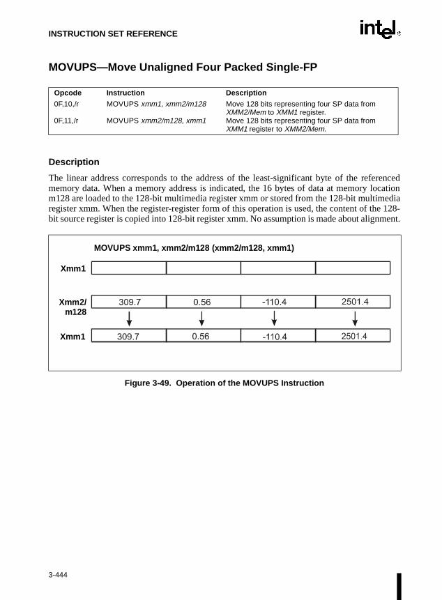
INSTRUCTION SET REFERENCE
MOVUPS—Move Unaligned Four Packed Single-FP
Description
The linear address corresponds to the address of the least-significant byte of the referencedmemory data. When a memory address is indicated, the 16 bytes of data at memory locationm128 are loaded to the 128-bit multimedia register xmm or stored from the 128-bit multimediaregister xmm. When the register-register form of this operation is used, the content of the 128-bit source register is copied into 128-bit register xmm. No assumption is made about alignment.
Figure 3-49. Operation of the MOVUPS Instruction
Opcode Instruction Description
0F,10,/r
0F,11,/r
MOVUPS xmm1, xmm2/m128
MOVUPS xmm2/m128, xmm1
Move 128 bits representing four SP data from XMM2/Mem to XMM1 register.Move 128 bits representing four SP data from XMM1 register to XMM2/Mem.
Xmm1
Xmm2/m128
Xmm1
MOVUPS xmm1, xmm2/m128 (xmm2/m128, xmm1)
3-444

INSTRUCTION SET REFERENCE
MOVUPS—Move Unaligned Four Packed Single-FP (Continued)
Operation
IF (destination = xmm) THENIF (SRC = m128)THEN(* load instruction *)
DEST[127-0] = m128;ELSE (* move instruction *)
DEST[127-0] = SRC[127-0];FI
ELSE IF (destination = m128) THEN(* store instruction *)
m128 = SRC[127-0];ELSE (* move instruction *)
DEST[127-0] = SRC[127-0];FI
FI
Intel C/C++ Compiler Intrinsic Equivalent
__m128 _mm_loadu_ps(float * p)
Loads four SP FP values. The address need not be 16-byte-aligned.
void_mm_storeu_ps(float *p, __m128 a)
Stores four SP FP values. The address need not be 16-byte-aligned.
Exceptions
None.
Numeric Exceptions
None.
3-445

INSTRUCTION SET REFERENCE
MOVUPS—Move Unaligned Four Packed Single-FP (Continued)
Protected Mode Exceptions
#GP(0) For an illegal memory operand effective address in the CS, DS, ES, FS, orGS segments.
#SS(0) For an illegal address in the SS segment.
#PF (fault-code For a page fault.
#UD If CR0.EM = 1.
#AC For unaligned memory reference if the current privilege level is 3.
#NM If TS bit in CR0 is set.
Real Address Mode Exceptions
Interrupt 13 If any part of the operand would lie outside of the effective address spacefrom 0 to 0FFFFH.
#UD If CR0.EM = 1.
#NM If TS bit in CR0 is set.
Virtual 8086 Mode Exceptions
Same exceptions as in Real Address Mode.
#AC For unaligned memory reference if the current privilege level is 3.
#PF (fault-code) For a page fault.
Comments
MOVUPS should be used with SP FP numbers when that data is known to be unaligned.Theusage of this instruction should be limited to the cases where the aligned restriction is hard orimpossible to meet. Streaming SIMD Extension implementations guarantee optimum unalignedsupport for MOVUPS. Efficient Streaming SIMD Extension applications should mainly rely onMOVAPS, not MOVUPS, when dealing with aligned data.
The usage of Repeat-NE (F2H) and Operand Size (66H) prefixes is reserved. Differentprocessor implementations may handle these prefixes differently. Usage of these prefixes withMOVUPS risks incompatibility with future processors.
A linear address of the 128 bit data access, while executing in 16-bit mode, that overlaps the endof a 16-bit segment is not allowed and is defined as reserved behavior. Different processorimplementations may/may not raise a GP fault in this case if the segment limit has beenexceeded. Additionally, the address that spans the end of the segment may/may not wrap aroundto the beginning of the segment.
3-446

INSTRUCTION SET REFERENCE
MOVZX—Move with Zero-Extend
Description
This instruction copies the contents of the source operand (register or memory location) to thedestination operand (register) and zero extends the value to 16 or 32 bits. The size of theconverted value depends on the operand-size attribute.
Operation
DEST ← ZeroExtend(SRC);
Flags Affected
None.
Protected Mode Exceptions
#GP(0) If a memory operand effective address is outside the CS, DS, ES, FS, orGS segment limit.
If the DS, ES, FS, or GS register contains a null segment selector.
#SS(0) If a memory operand effective address is outside the SS segment limit.
#PF(fault-code) If a page fault occurs.
#AC(0) If alignment checking is enabled and an unaligned memory reference ismade while the current privilege level is 3.
Real-Address Mode Exceptions
#GP If a memory operand effective address is outside the CS, DS, ES, FS, orGS segment limit.
#SS If a memory operand effective address is outside the SS segment limit.
Opcode Instruction Description
0F B6 /r MOVZX r16,r/m8 Move byte to word with zero-extension
0F B6 /r MOVZX r32,r/m8 Move byte to doubleword, zero-extension
0F B7 /r MOVZX r32,r/m16 Move word to doubleword, zero-extension
3-447

INSTRUCTION SET REFERENCE
MOVZX—Move with Zero-Extend (Continued)
Virtual-8086 Mode Exceptions
#GP(0) If a memory operand effective address is outside the CS, DS, ES, FS, orGS segment limit.
#SS(0) If a memory operand effective address is outside the SS segment limit.
#PF(fault-code) If a page fault occurs.
#AC(0) If alignment checking is enabled and an unaligned memory reference ismade.
3-448

INSTRUCTION SET REFERENCE
MUL—Unsigned Multiply
Description
This instruction performs an unsigned multiplication of the first operand (destination operand)and the second operand (source operand) and stores the result in the destination operand. Thedestination operand is an implied operand located in register AL, AX or EAX (depending on thesize of the operand); the source operand is located in a general-purpose register or a memorylocation. The action of this instruction and the location of the result depends on the opcode andthe operand size as shown in the following table.
:
The result is stored in register AX, register pair DX:AX, or register pair EDX:EAX (dependingon the operand size), with the high-order bits of the product contained in register AH, DX, orEDX, respectively. If the high-order bits of the product are 0, the CF and OF flags are cleared;otherwise, the flags are set.
Operation
IF byte operationTHEN
AX ← AL ∗ SRCELSE (* word or doubleword operation *)
IF OperandSize = 16THEN
DX:AX ← AX ∗ SRCELSE (* OperandSize = 32 *)
EDX:EAX ← EAX ∗ SRCFI;
FI;
Flags Affected
The OF and CF flags are cleared to 0 if the upper half of the result is 0; otherwise, they are setto 1. The SF, ZF, AF, and PF flags are undefined.
Opcode Instruction Description
F6 /4 MUL r/m8 Unsigned multiply (AX ← AL ∗ r/m8)
F7 /4 MUL r/m16 Unsigned multiply (DX:AX ← AX ∗ r/m16)
F7 /4 MUL r/m32 Unsigned multiply (EDX:EAX ← EAX ∗ r/m32)
Operand Size Source 1 Source 2 Destination
Byte AL r/m8 AX
Word AX r/m16 DX:AX
Doubleword EAX r/m32 EDX:EAX
3-449
INSTRUCTION SET REFERENCE
MUL—Unsigned Multiply (Continued)
Protected Mode Exceptions
#GP(0) If a memory operand effective address is outside the CS, DS, ES, FS, orGS segment limit.
If the DS, ES, FS, or GS register contains a null segment selector.
#SS(0) If a memory operand effective address is outside the SS segment limit.
#PF(fault-code) If a page fault occurs.
#AC(0) If alignment checking is enabled and an unaligned memory reference ismade while the current privilege level is 3.
Real-Address Mode Exceptions
#GP If a memory operand effective address is outside the CS, DS, ES, FS, orGS segment limit.
#SS If a memory operand effective address is outside the SS segment limit.
Virtual-8086 Mode Exceptions
#GP(0) If a memory operand effective address is outside the CS, DS, ES, FS, orGS segment limit.
#SS(0) If a memory operand effective address is outside the SS segment limit.
#PF(fault-code) If a page fault occurs.
#AC(0) If alignment checking is enabled and an unaligned memory reference ismade.
3-450

INSTRUCTION SET REFERENCE
MULPS—Packed Single-FP Multiply
Description
The MULPS instructions multiply the packed SP FP numbers of both their operands.
Figure 3-50. Operation of the MULPS Instruction
Operation
DEST[31-0] = DEST[31-0] * SRC/m128[31-0];DEST[63-32] = DEST[63-32] * SRC/m128[63-32];DEST[95-64] = DEST[95-64] * SRC/m128[95-64];DEST[127-96] = DEST[127-96] * SRC/m128[127-96];
Intel C/C++ Compiler Intrinsic Equivalent
__m128 _mm_mul_ps(__m128 a, __m128 b)
Multiplies the four SP FP values of a and b.
Opcode Instruction Description
0F,59,/r MULPS xmm1, xmm2/m128 Multiply packed SP FP numbers in XMM2/Mem to XMM1.
∗ ∗ ∗ ∗Xmm1
Xmm2/m128
Xmm1
MULPS xmm1, xmm2/m128
= = ==
3-451

INSTRUCTION SET REFERENCE
MULPS—Packed Single-FP Multiply (Continued)
Exceptions
General protection exception if not aligned on 16-byte boundary, regardless of segment.
Numeric Exceptions
Overflow, Underflow, Invalid, Precision, Denormal.
Protected Mode Exceptions
#GP(0) For an illegal memory operand effective address in the CS, DS, ES, FS, orGS segments.
#SS(0) For an illegal address in the SS segment.
#PF(fault-code) For a page fault.
#UD If CR0.EM = 1.
#NM If TS bit in CR0 is set.
#XM For an unmasked Streaming SIMD Extension numeric exception(CR4.OSXMMEXCPT =1).
#UD For an unmasked Streaming SIMD Extension numeric exception(CR4.OSXMMEXCPT =0).
Real Address Mode Exceptions
Interrupt 13 If any part of the operand would lie outside of the effective address spacefrom 0 to 0FFFFH.
#UD If CR0.EM = 1.
#NM If TS bit in CR0 is set.
#XM For an unmasked Streaming SIMD Extension numeric exception(CR4.OSXMMEXCPT =1).
#UD For an unmasked Streaming SIMD Extension numeric exception(CR4.OSXMMEXCPT =0).
Virtual 8086 Mode Exceptions
Same exceptions as in Real Address Mode.
#PF(fault-code) For a page fault.
3-452

INSTRUCTION SET REFERENCE
MULSS—Scalar Single-FP Multiply
Description
The MULSS instructions multiply the lowest SP FP numbers of both their operands; the upperthree fields are passed through from xmm1.
Figure 3-51. Operation of the MULSS Instruction
Operation
DEST[31-0] = DEST[31-0] * SRC/m32[31-0];DEST[63-32] = DEST[63-32];DEST[95-64] = DEST[95-64];DEST[127-96] = DEST[127-96];
Intel C/C++ Compiler Intrinsic Equivalent
__m128 _mm_mul_ss(__m128 a, __m128 b)
Multiplies the lower SP FP values of a and b; the upper three SP FP values are passed throughfrom a.
Exceptions
None.
Numeric Exceptions
Overflow, Underflow, Invalid, Precision, Denormal.
Opcode Instruction Description
F3,0F,59,/r MULSS xmm1 xmm2/m32 Multiply the lowest SP FP number in XMM2/Mem to XMM1.
Xmm1
Xmm2/m128
Xmm1
MULSS xmm1, xmm2/m128
2501.4
-4.75
∗ ∗ ∗∗
-11881.65
= = = =
3-453

INSTRUCTION SET REFERENCE
MULSS—Scalar Single-FP Multiply (Continued)
Protected Mode Exceptions
#GP(0) For an illegal memory operand effective address in the CS, DS, ES, FS, orGS segments.
#SS(0) For an illegal address in the SS segment.
#PF (fault-code) For a page fault.
#UD If CR0.EM = 1.
#NM If TS bit in CR0 is set.
#AC For unaligned memory reference. To enable #AC exceptions, three condi-tions must be true(CR0.AM is set; EFLAGS.AC is set; current CPL is 3).
#XM For an unmasked Streaming SIMD Extension numeric exception(CR4.OSXMMEXCPT =1).
#UD For an unmasked Streaming SIMD Extension numeric exception(CR4.OSXMMEXCPT =0).
Real Address Mode Exceptions
Interrupt 13 If any part of the operand would lie outside of the effective address spacefrom 0 to 0FFFFH.
#UD If CR0.EM = 1.
#NM If TS bit in CR0 is set.
#XM For an unmasked Streaming SIMD Extension numeric exception(CR4.OSXMMEXCPT =1).
#UD For an unmasked Streaming SIMD Extension numeric exception(CR4.OSXMMEXCPT =0).
Virtual 8086 Mode Exceptions
Same exceptions as in Real Address Mode.
#AC For unaligned memory reference if the current privilege level is 3.
#PF (fault-code) For a page fault.
3-454

INSTRUCTION SET REFERENCE
NEG—Two's Complement Negation
Description
This instruction replaces the value of operand (the destination operand) with its two’s comple-ment. (This operation is equivalent to subtracting the operand from 0.) The destination operandis located in a general-purpose register or a memory location.
Operation
IF DEST = 0 THEN CF ← 0 ELSE CF ← 1;
FI;DEST ← – (DEST)
Flags Affected
The CF flag cleared to 0 if the source operand is 0; otherwise it is set to 1. The OF, SF, ZF, AF,and PF flags are set according to the result.
Protected Mode Exceptions
#GP(0) If the destination is located in a nonwritable segment.
If a memory operand effective address is outside the CS, DS, ES, FS, orGS segment limit.
If the DS, ES, FS, or GS register contains a null segment selector.
#SS(0) If a memory operand effective address is outside the SS segment limit.
#PF(fault-code) If a page fault occurs.
#AC(0) If alignment checking is enabled and an unaligned memory reference ismade while the current privilege level is 3.
Real-Address Mode Exceptions
#GP If a memory operand effective address is outside the CS, DS, ES, FS, orGS segment limit.
#SS If a memory operand effective address is outside the SS segment limit.
Opcode Instruction Description
F6 /3 NEG r/m8 Two’s complement negate r/m8
F7 /3 NEG r/m16 Two’s complement negate r/m16
F7 /3 NEG r/m32 Two’s complement negate r/m32
3-455

INSTRUCTION SET REFERENCE
NEG—Two's Complement Negation (Continued)
Virtual-8086 Mode Exceptions
#GP(0) If a memory operand effective address is outside the CS, DS, ES, FS, orGS segment limit.
#SS(0) If a memory operand effective address is outside the SS segment limit.
#PF(fault-code) If a page fault occurs.
#AC(0) If alignment checking is enabled and an unaligned memory reference ismade.
3-456

INSTRUCTION SET REFERENCE
NOP—No Operation
Description
This instruction performs no operation. This instruction is a one-byte instruction that takes upspace in the instruction stream but does not affect the machine context, except the EIP register.
The NOP instruction is an alias mnemonic for the XCHG (E)AX, (E)AX instruction.
Flags Affected
None.
Exceptions (All Operating Modes)
None.
Opcode Instruction Description
90 NOP No operation
3-457

INSTRUCTION SET REFERENCE
NOT—One's Complement Negation
Description
This instruction performs a bitwise NOT operation (each 1 is cleared to 0, and each 0 is set to1) on the destination operand and stores the result in the destination operand location. The desti-nation operand can be a register or a memory location.
Operation
DEST ← NOT DEST;
Flags Affected
None.
Protected Mode Exceptions
#GP(0) If the destination operand points to a nonwritable segment.
If a memory operand effective address is outside the CS, DS, ES, FS, orGS segment limit.
If the DS, ES, FS, or GS register contains a null segment selector.
#SS(0) If a memory operand effective address is outside the SS segment limit.
#PF(fault-code) If a page fault occurs.
#AC(0) If alignment checking is enabled and an unaligned memory reference ismade while the current privilege level is 3.
Real-Address Mode Exceptions
#GP If a memory operand effective address is outside the CS, DS, ES, FS, orGS segment limit.
#SS If a memory operand effective address is outside the SS segment limit.
Opcode Instruction Description
F6 /2 NOT r/m8 Reverse each bit of r/m8
F7 /2 NOT r/m16 Reverse each bit of r/m16
F7 /2 NOT r/m32 Reverse each bit of r/m32
3-458

INSTRUCTION SET REFERENCE
NOT—One's Complement Negation (Continued)
Virtual-8086 Mode Exceptions
#GP(0) If a memory operand effective address is outside the CS, DS, ES, FS, orGS segment limit.
#SS(0) If a memory operand effective address is outside the SS segment limit.
#PF(fault-code) If a page fault occurs.
#AC(0) If alignment checking is enabled and an unaligned memory reference ismade.
3-459

INSTRUCTION SET REFERENCE
OR—Logical Inclusive OR
Description
This instruction performs a bitwise inclusive OR operation between the destination (first) andsource (second) operands and stores the result in the destination operand location. The sourceoperand can be an immediate, a register, or a memory location; the destination operand can bea register or a memory location. (However, two memory operands cannot be used in one instruc-tion.) Each bit of the result of the OR instruction is 0 if both corresponding bits of the operandsare 0; otherwise, each bit is 1.
Operation
DEST ← DEST OR SRC;
Flags Affected
The OF and CF flags are cleared; the SF, ZF, and PF flags are set according to the result. Thestate of the AF flag is undefined.
Opcode Instruction Description
0C ib OR AL,imm8 AL OR imm8
0D iw OR AX,imm16 AX OR imm16
0D id OR EAX,imm32 EAX OR imm32
80 /1 ib OR r/m8,imm8 r/m8 OR imm8
81 /1 iw OR r/m16,imm16 r/m16 OR imm16
81 /1 id OR r/m32,imm32 r/m32 OR imm32
83 /1 ib OR r/m16,imm8 r/m16 OR imm8 (sign-extended)
83 /1 ib OR r/m32,imm8 r/m32 OR imm8 (sign-extended)
08 /r OR r/m8,r8 r/m8 OR r8
09 /r OR r/m16,r16 r/m16 OR r16
09 /r OR r/m32,r32 r/m32 OR r32
0A /r OR r8,r/m8 r8 OR r/m8
0B /r OR r16,r/m16 r16 OR r/m16
0B /r OR r32,r/m32 r32 OR r/m32
3-460

INSTRUCTION SET REFERENCE
OR—Logical Inclusive OR (Continued)
Protected Mode Exceptions
#GP(0) If the destination operand points to a nonwritable segment.
If a memory operand effective address is outside the CS, DS, ES, FS, orGS segment limit.
If the DS, ES, FS, or GS register contains a null segment selector.
#SS(0) If a memory operand effective address is outside the SS segment limit.
#PF(fault-code) If a page fault occurs.
#AC(0) If alignment checking is enabled and an unaligned memory reference ismade while the current privilege level is 3.
Real-Address Mode Exceptions
#GP If a memory operand effective address is outside the CS, DS, ES, FS, orGS segment limit.
#SS If a memory operand effective address is outside the SS segment limit.
Virtual-8086 Mode Exceptions
#GP(0) If a memory operand effective address is outside the CS, DS, ES, FS, orGS segment limit.
#SS(0) If a memory operand effective address is outside the SS segment limit.
#PF(fault-code) If a page fault occurs.
#AC(0) If alignment checking is enabled and an unaligned memory reference ismade.
3-461

INSTRUCTION SET REFERENCE
ORPS—Bit-wise Logical OR for Single-FP Data
Description
The ORPS instructions return a bit-wise logical OR between xmm1 and xmm2/mem.
Figure 3-52. Operation of the ORPS Instruction
Operation
DEST[127-0] |= SRC/m128[127-0];
Intel C/C++ Compiler Intrinsic Equivalent
__m128 _mm_or_ps(__m128 a, __m128 b)
Computes the bitwise OR of the four SP FP values of a and b.
Exceptions
General protection exception if not aligned on 16-byte boundary, regardless of segment.
Opcode Instruction Description
0F,56,/r ORPS xmm1, xmm2/m128 OR 128 bits from XMM2/Mem to XMM1 register.
Xmm1
Xmm1
Xmm2/m128
0xEB460053 0xFB37D019
0x00FF00AA 0x00FF00AA
0x00038AC2 0x999333CC
0xEBFF00FB
= = = =
3-462

INSTRUCTION SET REFERENCE
ORPS—Bit-wise Logical OR for Single-FP Data (Continued)
Numeric Exceptions
None.
Protected Mode Exceptions
#GP(0) For an illegal memory operand effective address in the CS, DS, ES, FS, orGS segments.
#SS(0) For an illegal address in the SS segment.
#PF(fault-code) For a page fault.
#UD If CR0.EM = 1.
#NM If TS bit in CR0 is set.
Real Address Mode Exceptions
Interrupt 13 If any part of the operand would lie outside of the effective address spacefrom 0 to 0FFFFH.
#UD If CR0.EM = 1.
#NM If TS bit in CR0 is set.
Virtual 8086 Mode Exceptions
Same exceptions as in Real Address Mode.
#PF(fault-code) For a page fault.
Comments
The usage of Repeat Prefix (F3H) with ORPS is reserved. Different processor implementationsmay handle this prefix differently. Usage of this prefix with ORPS risks incompatibility withfuture processors.
3-463

INSTRUCTION SET REFERENCE
dressl,
OUT—Output to Port
Description
This instruction copies the value from the second operand (source operand) to the I/O port spec-ified with the destination operand (first operand). The source operand can be register AL, AX,or EAX, depending on the size of the port being accessed (8, 16, or 32 bits, respectively); thedestination operand can be a byte-immediate or the DX register. Using a byte immediate allowsI/O port addresses 0 to 255 to be accessed; using the DX register as a source operand allows I/Oports from 0 to 65,535 to be accessed.
The size of the I/O port being accessed is determined by the opcode for an 8-bit I/O port or bythe operand-size attribute of the instruction for a 16- or 32-bit I/O port.
At the machine code level, I/O instructions are shorter when accessing 8-bit I/O ports. Here, theupper eight bits of the port address will be 0.
This instruction is only useful for accessing I/O ports located in the processor’s I/O adspace. Refer to Chapter 10, Input/Output of the Intel Architecture Software Developer’s ManuaVolume 1, for more information on accessing I/O ports in the I/O address space.
Intel Architecture Compatibility
After executing an OUT instruction, the Pentium® processor insures that the EWBE# pin hasbeen sampled active before it begins to execute the next instruction. (Note that the instructioncan be prefetched if EWBE# is not active, but it will not be executed until the EWBE# pin issampled active.) Only the P6 family of processors has the EWBE# pin; the other Intel Architec-ture processors do not.
Opcode Instruction Description
E6 ib OUT imm8, AL Output byte in AL to I/O port address imm8
E7 ib OUT imm8, AX Output word in AX to I/O port address imm8
E7 ib OUT imm8, EAX Output doubleword in EAX to I/O port address imm8
EE OUT DX, AL Output byte in AL to I/O port address in DX
EF OUT DX, AX Output word in AX to I/O port address in DX
EF OUT DX, EAX Output doubleword in EAX to I/O port address in DX
3-464

INSTRUCTION SET REFERENCE
OUT—Output to Port (Continued)
Operation
IF ((PE = 1) AND ((CPL > IOPL) OR (VM = 1)))THEN (* Protected mode with CPL > IOPL or virtual-8086 mode *)
IF (Any I/O Permission Bit for I/O port being accessed = 1)THEN (* I/O operation is not allowed *)
#GP(0);ELSE ( * I/O operation is allowed *)
DEST ← SRC; (* Writes to selected I/O port *)FI;
ELSE (Real Mode or Protected Mode with CPL ≤ IOPL *)DEST ← SRC; (* Writes to selected I/O port *)
FI;
Flags Affected
None.
Protected Mode Exceptions
#GP(0) If the CPL is greater than (has less privilege) the I/O privilege level (IOPL)and any of the corresponding I/O permission bits in TSS for the I/O portbeing accessed is 1.
Real-Address Mode Exceptions
None.
Virtual-8086 Mode Exceptions
#GP(0) If any of the I/O permission bits in the TSS for the I/O port being accessedis 1.
3-465

INSTRUCTION SET REFERENCE
nds”TS
e, theddress,
docu-. That,
ion is
of thesumedonic:
t, thee DF
flag by ne
OUTS/OUTSB/OUTSW/OUTSD—Output String to Port
Description
These instructions copy data from the source operand (second operand) to the I/O port specifiedwith the destination operand (first operand). The source operand is a memory location, theaddress of which is read from either the DS:EDI or the DS:DI registers (depending on theaddress-size attribute of the instruction, 32 or 16, respectively). The DS segment may be over-ridden with a segment override prefix. The destination operand is an I/O port address (from 0 to65,535) that is read from the DX register. The size of the I/O port being accessed (that is, thesize of the source and destination operands) is determined by the opcode for an 8-bit I/O port orby the operand-size attribute of the instruction for a 16- or 32-bit I/O port.
At the assembly-code level, two forms of this instruction are allowed: the “explicit-operaform and the “no-operands” form. The explicit-operands form (specified with the OUmnemonic) allows the source and destination operands to be specified explicitly. Hersource operand should be a symbol that indicates the size of the I/O port and the source aand the destination operand must be DX. This explicit-operands form is provided to allow mentation; however, note that the documentation provided by this form can be misleadingis, the source operand symbol must specify the correct type (size) of the operand (byte, wordor doubleword), but it does not have to specify the correct location. The location is always spec-ified by the DS:(E)SI registers, which must be loaded correctly before the OUTS instructexecuted.
The no-operands form provides “short forms” of the byte, word, and doubleword versions OUTS instructions. Here also DS:(E)SI is assumed to be the source operand and DX is asto be the destination operand. The size of the I/O port is specified with the choice of mnemOUTSB (byte), OUTSW (word), or OUTSD (doubleword).
After the byte, word, or doubleword is transferred from the memory location to the I/O por(E)SI register is incremented or decremented automatically according to the setting of thflag in the EFLAGS register. (If the DF flag is 0, the (E)SI register is incremented; if the DFis 1, the (E)SI register is decremented.) The (E)SI register is incremented or decrementedfor byte operations, by two for word operations, or by four for doubleword operations.
Opcode Instruction Description
6E OUTS DX, m8 Output byte from memory location specified in DS:(E)SI to I/O port specified in DX
6F OUTS DX, m16 Output word from memory location specified in DS:(E)SI to I/O port specified in DX
6F OUTS DX, m32 Output doubleword from memory location specified in DS:(E)SI to I/O port specified in DX
6E OUTSB Output byte from memory location specified in DS:(E)SI to I/O port specified in DX
6F OUTSW Output word from memory location specified in DS:(E)SI to I/O port specified in DX
6F OUTSD Output doubleword from memory location specified in DS:(E)SI to I/O port specified in DX
3-466

INSTRUCTION SET REFERENCE
NEfix.
dressl,
OUTS/OUTSB/OUTSW/OUTSD—Output String to Port (Continued)
The OUTS, OUTSB, OUTSW, and OUTSD instructions can be preceded by the REP prefix forblock input of ECX bytes, words, or doublewords. Refer to “REP/REPE/REPZ/REP/REPNZ—Repeat String Operation Prefix” in this chapter for a description of the REP pre
This instruction is only useful for accessing I/O ports located in the processor’s I/O adspace. Refer to Chapter 10, Input/Output of the Intel Architecture Software Developer’s ManuaVolume 1, for more information on accessing I/O ports in the I/O address space.
Intel Architecture Compatibility
After executing an OUTS, OUTSB, OUTSW, or OUTSD instruction, the Pentium® processorinsures that the EWBE# pin has been sampled active before it begins to execute the next instruc-tion. (Note that the instruction can be prefetched if EWBE# is not active, but it will not beexecuted until the EWBE# pin is sampled active.) Only the P6 family of processors has theEWBE# pin. For the P6 family processors, upon execution of an OUTS, OUTSB, OUTSW, orOUTSD instruction, the P6 family of processor will not execute the next instruction until thedata phase of the transaction is complete.
3-467

INSTRUCTION SET REFERENCE
OUTS/OUTSB/OUTSW/OUTSD—Output String to Port (Continued)
Operation
IF ((PE = 1) AND ((CPL > IOPL) OR (VM = 1)))THEN (* Protected mode with CPL > IOPL or virtual-8086 mode *)
IF (Any I/O Permission Bit for I/O port being accessed = 1)THEN (* I/O operation is not allowed *)
#GP(0);ELSE ( * I/O operation is allowed *)
DEST ← SRC; (* Writes to I/O port *)FI;
ELSE (Real Mode or Protected Mode with CPL ≤ IOPL *)DEST ← SRC; (* Writes to I/O port *)
FI;IF (byte transfer)
THEN IF DF = 0THEN (E)SI ← (E)SI + 1; ELSE (E)SI ← (E)SI – 1;
FI;ELSE IF (word transfer)
THEN IF DF = 0THEN (E)SI ← (E)SI + 2; ELSE (E)SI ← (E)SI – 2;
FI;ELSE (* doubleword transfer *)
THEN IF DF = 0THEN (E)SI ← (E)SI + 4; ELSE (E)SI ← (E)SI – 4;
FI;FI;
FI;
Flags Affected
None.
3-468

INSTRUCTION SET REFERENCE
OUTS/OUTSB/OUTSW/OUTSD—Output String to Port (Continued)
Protected Mode Exceptions
#GP(0) If the CPL is greater than (has less privilege) the I/O privilege level (IOPL)and any of the corresponding I/O permission bits in TSS for the I/O portbeing accessed is 1.
If a memory operand effective address is outside the limit of the CS, DS,ES, FS, or GS segment.
If the segment register contains a null segment selector.
#PF(fault-code) If a page fault occurs.
#AC(0) If alignment checking is enabled and an unaligned memory reference ismade while the current privilege level is 3.
Real-Address Mode Exceptions
#GP If a memory operand effective address is outside the CS, DS, ES, FS, orGS segment limit.
#SS If a memory operand effective address is outside the SS segment limit.
Virtual-8086 Mode Exceptions
#GP(0) If any of the I/O permission bits in the TSS for the I/O port being accessedis 1.
#PF(fault-code) If a page fault occurs.
#AC(0) If alignment checking is enabled and an unaligned memory reference ismade.
3-469

INSTRUCTION SET REFERENCE
ister
PACKSSWB/PACKSSDW—Pack with Signed Saturation
Description
These instructions pack and saturate signed words into bytes (PACKSSWB) or signed double-words into words (PACKSSDW). The PACKSSWB instruction packs four signed words fromthe destination operand (first operand) and four signed words from the source operand (secondoperand) into eight signed bytes in the destination operand. If the signed value of a word isbeyond the range of a signed byte (that is, greater than 7FH or less than 80H), the saturated bytevalue of 7FH or 80H, respectively, is stored into the destination.
The PACKSSDW instruction packs two signed doublewords from the destination operand (firstoperand) and two signed doublewords from the source operand (second operand) into foursigned words in the destination operand (refer to Figure 3-53). If the signed value of a double-word is beyond the range of a signed word (that is, greater than 7FFFH or less than 8000H), thesaturated word value of 7FFFH or 8000H, respectively, is stored into the destination.
The destination operand for either the PACKSSWB or PACKSSDW instruction must be anMMX™ technology register; the source operand may be either an MMX™ technology regor a quadword memory location.
Opcode Instruction Description
0F 63 /r PACKSSWB mm, mm/m64
Packs and saturate pack four signed words from mm and four signed words from mm/m64 into eight signed bytes in mm.
0F 6B /r PACKSSDW mm, mm/m64
Pack and saturate two signed doublewords from mm and two signed doublewords from mm/m64 into four signed words in mm.
Figure 3-53. Operation of the PACKSSDW Instruction
mm/m64
mm
D C B A
D’ C’ B’ A’
mm
PACKSSDW mm, mm/m64
3-470

INSTRUCTION SET REFERENCE
PACKSSWB/PACKSSDW—Pack with Signed Saturation (Continued)
Operation
IF instruction is PACKSSWBTHEN
DEST(7..0) ← SaturateSignedWordToSignedByte DEST(15..0); DEST(15..8) ← SaturateSignedWordToSignedByte DEST(31..16);DEST(23..16) ← SaturateSignedWordToSignedByte DEST(47..32);DEST(31..24) ← SaturateSignedWordToSignedByte DEST(63..48);DEST(39..32) ← SaturateSignedWordToSignedByte SRC(15..0);DEST(47..40) ← SaturateSignedWordToSignedByte SRC(31..16);DEST(55..48) ← SaturateSignedWordToSignedByte SRC(47..32);DEST(63..56) ← SaturateSignedWordToSignedByte SRC(63..48);
ELSE (* instruction is PACKSSDW *)DEST(15..0) ← SaturateSignedDoublewordToSignedWord DEST(31..0);DEST(31..16) ← SaturateSignedDoublewordToSignedWord DEST(63..32);DEST(47..32) ← SaturateSignedDoublewordToSignedWord SRC(31..0);DEST(63..48) ← SaturateSignedDoublewordToSignedWord SRC(63..32);
FI;
Intel C/C++ Compiler Intrinsic Equivalents
Pre-4.0 Intel C/C++ Compiler intrinsic:
__m64 _m_packsswb (__m64 m1, __m64 m2)
Version 4.0 and later Intel C/C++ Compiler intrinsic:
__m64 _mm_packs_pi16(__m64 m1, __m64 m2)
Pack the four 16-bit values from m1 into the lower four 8-bit values of the result with signedsaturation, and pack the four 16-bit values from m2 into the upper four 8-bit values of the resultwith signed saturation.
Pre-4.0 Intel C/C++ Compiler intrinsic:
__m64 _m_packssdw (__m64 m1, __m64 m2)
Version 4.0 and later Intel C/C++ Compiler intrinsic:
__m64 _mm_packs_pi32 (__m64 m1, __m64 m2)
Pack the two 32-bit values from m1 into the lower two 16-bit values of the result with signedsaturation, and pack the two 32-bit values from m2 into the upper two 16-bit values of the resultwith signed saturation.
Flags Affected
None.
3-471

INSTRUCTION SET REFERENCE
PACKSSWB/PACKSSDW—Pack with Signed Saturation (Continued)
Protected Mode Exceptions
#GP(0) If a memory operand effective address is outside the CS, DS, ES, FS, orGS segment limit.
#SS(0) If a memory operand effective address is outside the SS segment limit.
#UD If EM in CR0 is set.
#NM If TS in CR0 is set.
#MF If there is a pending FPU exception.
#PF(fault-code) If a page fault occurs.
#AC(0) If alignment checking is enabled and an unaligned memory reference ismade while the current privilege level is 3.
Real-Address Mode Exceptions
#GP If any part of the operand lies outside of the effective address space from0 to FFFFH.
#UD If EM in CR0 is set.
#NM If TS in CR0 is set.
#MF If there is a pending FPU exception.
Virtual-8086 Mode Exceptions
#GP If any part of the operand lies outside of the effective address space from0 to FFFFH.
#UD If EM in CR0 is set.
#NM If TS in CR0 is set.
#MF If there is a pending FPU exception.
#PF(fault-code) If a page fault occurs.
#AC(0) If alignment checking is enabled and an unaligned memory reference ismade.
3-472

INSTRUCTION SET REFERENCE
ay be
PACKUSWB—Pack with Unsigned Saturation
Description
This instruction packs and saturates four signed words from the destination operand (firstoperand) and four signed words from the source operand (second operand) into eight unsignedbytes in the destination operand (refer to Figure 3-54). If the signed value of a word is beyondthe range of an unsigned byte (that is, greater than FFH or less than 00H), the saturated bytevalue of FFH or 00H, respectively, is stored into the destination.
The destination operand must be an MMX™ technology register; the source operand meither an MMX™ technology register or a quadword memory location.
Operation
DEST(7..0) ← SaturateSignedWordToUnsignedByte DEST(15..0); DEST(15..8) ← SaturateSignedWordToUnsignedByte DEST(31..16);DEST(23..16) ← SaturateSignedWordToUnsignedByte DEST(47..32);DEST(31..24) ← SaturateSignedWordToUnsignedByte DEST(63..48);DEST(39..32) ← SaturateSignedWordToUnsignedByte SRC(15..0);DEST(47..40) ← SaturateSignedWordToUnsignedByte SRC(31..16);DEST(55..48) ← SaturateSignedWordToUnsignedByte SRC(47..32);DEST(63..56) ← SaturateSignedWordToUnsignedByte SRC(63..48);
Opcode Instruction Description
0F 67 /r PACKUSWB mm, mm/m64
Pack and saturate four signed words from mm and four signed words from mm/m64 into eight unsigned bytes in mm.
Figure 3-54. Operation of the PACKUSWB Instruction
PACKUSWB mm, mm/m64mm/m64 mm
mm
3006014
H
G
F
E
H’
G’
F’
E’
D’
C’
B’
A’
D
C
B
A
3-473
INSTRUCTION SET REFERENCE
PACKUSWB—Pack with Unsigned Saturation (Continued)
Intel C/C++ Compiler Intrinsic Equivalent
Pre-4.0 Intel C/C++ Compiler intrinsic:
__m64 _m_packuswb(__m64 m1, __m64 m2)
Version 4.0 and later Intel C/C++ Compiler intrinsic:
__m64 _mm_packs_pu16(__m64 m1, __m64 m2)
Pack the four 16-bit values from m1 into the lower four 8-bit values of the result with unsignedsaturation, and pack the four 16-bit values from m2 into the upper four 8-bit values of the resultwith unsigned saturation.
Flags Affected
None.
Protected Mode Exceptions
#GP(0) If a memory operand effective address is outside the CS, DS, ES, FS, orGS segment limit.
#SS(0) If a memory operand effective address is outside the SS segment limit.
#UD If EM in CR0 is set.
#NM If TS in CR0 is set.
#MF If there is a pending FPU exception.
#PF(fault-code) If a page fault occurs.
#AC(0) If alignment checking is enabled and an unaligned memory reference ismade while the current privilege level is 3.
Real-Address Mode Exceptions
#GP If any part of the operand lies outside of the effective address space from0 to FFFFH.
#UD If EM in CR0 is set.
#NM If TS in CR0 is set.
#MF If there is a pending FPU exception.
3-474

INSTRUCTION SET REFERENCE
PACKUSWB—Pack with Unsigned Saturation (Continued)
Virtual-8086 Mode Exceptions
#GP If any part of the operand lies outside of the effective address space from0 to FFFFH.
#UD If EM in CR0 is set.
#NM If TS in CR0 is set.
#MF If there is a pending FPU exception.
#PF(fault-code) If a page fault occurs.
#AC(0) If alignment checking is enabled and an unaligned memory reference ismade.
3-475

INSTRUCTION SET REFERENCE
an be
nationo largeation
nationo largeperand
PADDB/PADDW/PADDD—Packed Add
Description
These instructions add the individual data elements (bytes, words, or doublewords) of the sourceoperand (second operand) to the individual data elements of the destination operand (firstoperand) (refer to Figure 3-55). If the result of an individual addition exceeds the range for thespecified data type (overflows), the result is wrapped around, meaning that the result is truncatedso that only the lower (least significant) bits of the result are returned (that is, the carry isignored).
The destination operand must be an MMX™ technology register; the source operand ceither an MMX™ technology register or a quadword memory location.
The PADDB instruction adds the bytes of the source operand to the bytes of the destioperand and stores the results to the destination operand. When an individual result is toto be represented in eight bits, the lower eight bits of the result are written to the destinoperand and therefore the result wraps around.
The PADDW instruction adds the words of the source operand to the words of the destioperand and stores the results to the destination operand. When an individual result is toto be represented in 16 bits, the lower 16 bits of the result are written to the destination oand therefore the result wraps around.
Opcode Instruction Description
0F FC /r PADDB mm, mm/m64
Add packed bytes from mm/m64 to packed bytes in mm.
0F FD /r PADDW mm, mm/m64
Add packed words from mm/m64 to packed words in mm.
0F FE /r PADDD mm, mm/m64
Add packed doublewords from mm/m64 to packed doublewords in mm.
Figure 3-55. Operation of the PADDW Instruction
PADDW mm, mm/m64
mm
mm/m64
mm
1000000000000000 0111111100111000
+ ++ +1111111111111111 0001011100000111
0111111111111111 1001011000111111
3006015
3-476

INSTRUCTION SET REFERENCE
ration”
PADDB/PADDW/PADDD—Packed Add (Continued)The PADDD instruction adds the doublewords of the source operand to the doublewords of thedestination operand and stores the results to the destination operand. When an individual resultis too large to be represented in 32 bits, the lower 32 bits of the result are written to the destina-tion operand and therefore the result wraps around.
Note that like the integer ADD instruction, the PADDB, PADDW, and PADDD instructions canoperate on either unsigned or signed (two’s complement notation) packed integers. Unlike theinteger instructions, none of the MMX™ instructions affect the EFLAGS register. WithMMX™ instructions, there are no carry or overflow flags to indicate when overflow hasoccurred, so the software must control the range of values or else use the “with satuMMX™ instructions.
Operation
IF instruction is PADDBTHEN
DEST(7..0) ← DEST(7..0) + SRC(7..0); DEST(15..8) ← DEST(15..8) + SRC(15..8);DEST(23..16) ← DEST(23..16)+ SRC(23..16);DEST(31..24) ← DEST(31..24) + SRC(31..24);DEST(39..32) ← DEST(39..32) + SRC(39..32);DEST(47..40) ← DEST(47..40)+ SRC(47..40);DEST(55..48) ← DEST(55..48) + SRC(55..48);DEST(63..56) ← DEST(63..56) + SRC(63..56);
ELSEIF instruction is PADDWTHEN
DEST(15..0) ← DEST(15..0) + SRC(15..0);DEST(31..16) ← DEST(31..16) + SRC(31..16);DEST(47..32) ← DEST(47..32) + SRC(47..32);DEST(63..48) ← DEST(63..48) + SRC(63..48);
ELSE (* instruction is PADDD *)DEST(31..0) ← DEST(31..0) + SRC(31..0);DEST(63..32) ← DEST(63..32) + SRC(63..32);
FI;
3-477

INSTRUCTION SET REFERENCE
PADDB/PADDW/PADDD—Packed Add (Continued)
Intel C/C++ Compiler Intrinsic Equivalents
Pre-4.0 Intel C/C++ Compiler intrinsic:
__m64 _m_paddb(__m64 m1, __m64 m2)
Version 4.0 and later Intel C/C++ Compiler intrinsic:
__m64 _mm_add_pi8(__m64 m1, __m64 m2)
Add the eight 8-bit values in m1 to the eight 8-bit values in m2.
Pre-4.0 Intel C/C++ Compiler intrinsic:
__m64 _m_paddw(__m64 m1, __m64 m2)
Version 4.0 and later Intel C/C++ Compiler intrinsic:
__m64 _mm_addw_pi16(__m64 m1, __m64 m2)
Add the four 16-bit values in m1 to the four 16-bit values in m2.
Pre-4.0 Intel C/C++ Compiler intrinsic:
__m64 _m_paddd(__m64 m1, __m64 m2)
Version 4.0 and later Intel C/C++ Compiler intrinsic:
__m64 _mm_add_pi32(__m64 m1, __m64 m2)
Add the two 32-bit values in m1 to the two 32-bit values in m2.
Flags Affected
None.
Protected Mode Exceptions
#GP(0) If a memory operand effective address is outside the CS, DS, ES, FS, orGS segment limit.
#SS(0) If a memory operand effective address is outside the SS segment limit.
#UD If EM in CR0 is set.
#NM If TS in CR0 is set.
#MF If there is a pending FPU exception.
#PF(fault-code) If a page fault occurs.
#AC(0) If alignment checking is enabled and an unaligned memory reference ismade while the current privilege level is 3.
3-478
INSTRUCTION SET REFERENCE
PADDB/PADDW/PADDD—Packed Add (Continued)
Real-Address Mode Exceptions
#GP If any part of the operand lies outside of the effective address space from0 to FFFFH.
#UD If EM in CR0 is set.
#NM If TS in CR0 is set.
#MF If there is a pending FPU exception.
Virtual-8086 Mode Exceptions
#GP If any part of the operand lies outside of the effective address space from0 to FFFFH.
#UD If EM in CR0 is set.
#NM If TS in CR0 is set.
#MF If there is a pending FPU exception.
#PF(fault-code) If a page fault occurs.
#AC(0) If alignment checking is enabled and an unaligned memory reference ismade.
3-479

INSTRUCTION SET REFERENCE
tech-dword
of thel resultturated
rds ofividualH), thend.
PADDSB/PADDSW—Packed Add with Saturation
Description
These instructions add the individual signed data elements (bytes or words) of the sourceoperand (second operand) to the individual signed data elements of the destination operand (firstoperand) (refer to Figure 3-56). If the result of an individual addition exceeds the range for thespecified data type, the result is saturated. The destination operand must be an MMX™nology register; the source operand can be either an MMX™ technology register or a quamemory location.
The PADDSB instruction adds the signed bytes of the source operand to the signed bytesdestination operand and stores the results to the destination operand. When an individuais beyond the range of a signed byte (that is, greater than 7FH or less than 80H), the sabyte value of 7FH or 80H, respectively, is written to the destination operand.
The PADDSW instruction adds the signed words of the source operand to the signed wothe destination operand and stores the results to the destination operand. When an indresult is beyond the range of a signed word (that is, greater than 7FFFH or less than 8000saturated word value of 7FFFH or 8000H, respectively, is written to the destination opera
Opcode Instruction Description
0F EC /r PADDSB mm, mm/m64
Add signed packed bytes from mm/m64 to signed packed bytes in mm and saturate.
0F ED /r PADDSW mm, mm/m64
Add signed packed words from mm/m64 to signed packed words in mm and saturate.
Figure 3-56. Operation of the PADDSW Instruction
PADDSW mm, mm/m64
mm
mm/m64
mm
1000000000000000 0111111100111000
+ ++ +1111111111111111 0001011100000111
1000000000000000 0111111111111111
3006016
3-480

INSTRUCTION SET REFERENCE
PADDSB/PADDSW—Packed Add with Saturation (Continued)
Operation
IF instruction is PADDSBTHEN
DEST(7..0) ← SaturateToSignedByte(DEST(7..0) + SRC (7..0)) ;DEST(15..8) ← SaturateToSignedByte(DEST(15..8) + SRC(15..8) );
DEST(23..16) ← SaturateToSignedByte(DEST(23..16)+ SRC(23..16) );DEST(31..24) ← SaturateToSignedByte(DEST(31..24) + SRC(31..24) );DEST(39..32) ← SaturateToSignedByte(DEST(39..32) + SRC(39..32) );DEST(47..40) ← SaturateToSignedByte(DEST(47..40)+ SRC(47..40) );DEST(55..48) ← SaturateToSignedByte(DEST(55..48) + SRC(55..48) );DEST(63..56) ← SaturateToSignedByte(DEST(63..56) + SRC(63..56) );
ELSE { (* instruction is PADDSW *)DEST(15..0) ← SaturateToSignedWord(DEST(15..0) + SRC(15..0) );DEST(31..16) ← SaturateToSignedWord(DEST(31..16) + SRC(31..16) );DEST(47..32) ← SaturateToSignedWord(DEST(47..32) + SRC(47..32) );DEST(63..48) ← SaturateToSignedWord(DEST(63..48) + SRC(63..48) );
FI;
Intel C/C++ Compiler Intrinsic Equivalents
Pre-4.0 Intel C/C++ Compiler intrinsic:
__m64 _m_paddsb(__m64 m1, __m64 m2)
Version 4.0 and later Intel C/C++ Compiler intrinsic:
__m64 _mm_adds_pi8(__m64 m1, __m64 m2)
Add the eight signed 8-bit values in m1 to the eight signed 8-bit values in m2 and saturate.
Pre-4.0 Intel C/C++ Compiler intrinsic:
__m64 _m_paddsw(__m64 m1, __m64 m2)
Version 4.0 and later Intel C/C++ Compiler intrinsic:
__m64 _mm_adds_pi16(__m64 m1, __m64 m2)
Add the four signed 16-bit values in m1 to the four signed 16-bit values in m2 and saturate.
Flags Affected
None.
3-481
INSTRUCTION SET REFERENCE
PADDSB/PADDSW—Packed Add with Saturation (Continued)
Protected Mode Exceptions
#GP(0) If a memory operand effective address is outside the CS, DS, ES, FS, orGS segment limit.
#SS(0) If a memory operand effective address is outside the SS segment limit.
#UD If EM in CR0 is set.
#NM If TS in CR0 is set.
#MF If there is a pending FPU exception.
#PF(fault-code) If a page fault occurs.
#AC(0) If alignment checking is enabled and an unaligned memory reference ismade while the current privilege level is 3.
Real-Address Mode Exceptions
#GP If any part of the operand lies outside of the effective address space from0 to FFFFH.
#UD If EM in CR0 is set.
#NM If TS in CR0 is set.
#MF If there is a pending FPU exception.
Virtual-8086 Mode Exceptions
#GP If any part of the operand lies outside of the effective address space from0 to FFFFH.
#UD If EM in CR0 is set.
#NM If TS in CR0 is set.
#MF If there is a pending FPU exception.
#PF(fault-code) If a page fault occurs.
#AC(0) If alignment checking is enabled and an unaligned memory reference ismade.
3-482

INSTRUCTION SET REFERENCE
MX™
d bytesividual
nsigned
ignedan indi-turated
PADDUSB/PADDUSW—Packed Add Unsigned with Saturation
Description
These instructions add the individual unsigned data elements (bytes or words) of the packedsource operand (second operand) to the individual unsigned data elements of the packed desti-nation operand (first operand) (refer to Figure 3-57). If the result of an individual additionexceeds the range for the specified unsigned data type, the result is saturated. The destinationoperand must be an MMX™ technology register; the source operand can be either an Mtechnology register or a quadword memory location.
The PADDUSB instruction adds the unsigned bytes of the source operand to the unsigneof the destination operand and stores the results to the destination operand. When an indresult is beyond the range of an unsigned byte (that is, greater than FFH), the saturated ubyte value of FFH is written to the destination operand.
The PADDUSW instruction adds the unsigned words of the source operand to the unswords of the destination operand and stores the results to the destination operand. When vidual result is beyond the range of an unsigned word (that is, greater than FFFFH), the saunsigned word value of FFFFH is written to the destination operand.
Opcode Instruction Description
0F DC /r PADDUSB mm, mm/m64
Add unsigned packed bytes from mm/m64 to unsigned packed bytes in mm and saturate.
0F DD /r PADDUSW mm, mm/m64
Add unsigned packed words from mm/m64 to unsigned packed words in mm and saturate.
Figure 3-57. Operation of the PADDUSB Instruction
PADDUSB mm, mm/m64
mm
mm/m64
mm
10000000 01111111 00111000
11111111 00010111 00000111
11111111 10010110 00111111
+ ++ +
3006017
+ ++ +
3-483

INSTRUCTION SET REFERENCE
PADDUSB/PADDUSW—Packed Add Unsigned with Saturation (Continued)
Operation
IF instruction is PADDUSBTHEN
DEST(7..0) ← SaturateToUnsignedByte(DEST(7..0) + SRC (7..0) );DEST(15..8) ← SaturateToUnsignedByte(DEST(15..8) + SRC(15..8) );DEST(23..16) ← SaturateToUnsignedByte(DEST(23..16)+ SRC(23..16) );DEST(31..24) ← SaturateToUnsignedByte(DEST(31..24) + SRC(31..24) );DEST(39..32) ← SaturateToUnsignedByte(DEST(39..32) + SRC(39..32) );DEST(47..40) ← SaturateToUnsignedByte(DEST(47..40)+ SRC(47..40) );DEST(55..48) ← SaturateToUnsignedByte(DEST(55..48) + SRC(55..48) );DEST(63..56) ← SaturateToUnsignedByte(DEST(63..56) + SRC(63..56) );
ELSE { (* instruction is PADDUSW *)DEST(15..0) ← SaturateToUnsignedWord(DEST(15..0) + SRC(15..0) );DEST(31..16) ← SaturateToUnsignedWord(DEST(31..16) + SRC(31..16) );DEST(47..32) ← SaturateToUnsignedWord(DEST(47..32) + SRC(47..32) );DEST(63..48) ← SaturateToUnsignedWord(DEST(63..48) + SRC(63..48) );
FI;
Intel C/C++ Compiler Intrinsic Equivalents
Pre-4.0 Intel C/C++ Compiler intrinsic:
__m64 _m_paddusb(__m64 m1, __m64 m2)
Version 4.0 and later Intel C/C++ Compiler intrinsic:
__m64 _mm_adds_pu8(__m64 m1, __m64 m2)
Add the eight unsigned 8-bit values in m1 to the eight unsigned 8-bit values in m2 and saturate.
Pre-4.0 Intel C/C++ Compiler intrinsic:
__m64 _m_paddusw(__m64 m1, __m64 m2)
Version 4.0 and later Intel C/C++ Compiler intrinsic:
__m64 _mm_adds_pu16(__m64 m1, __m64 m2)
Add the four unsigned 16-bit values in m1 to the four unsigned 16-bit values in m2 and saturate.
Flags Affected
None.
3-484

INSTRUCTION SET REFERENCE
PADDUSB/PADDUSW—Packed Add Unsigned with Saturation (Continued)
Protected Mode Exceptions
#GP(0) If a memory operand effective address is outside the CS, DS, ES, FS, orGS segment limit.
#SS(0) If a memory operand effective address is outside the SS segment limit.
#UD If EM in CR0 is set.
#NM If TS in CR0 is set.
#MF If there is a pending FPU exception.
#PF(fault-code) If a page fault occurs.
#AC(0) If alignment checking is enabled and an unaligned memory reference ismade while the current privilege level is 3.
Real-Address Mode Exceptions
#GP If any part of the operand lies outside of the effective address space from0 to FFFFH.
#UD If EM in CR0 is set.
#NM If TS in CR0 is set.
#MF If there is a pending FPU exception.
Virtual-8086 Mode Exceptions
#GP If any part of the operand lies outside of the effective address space from0 to FFFFH.
#UD If EM in CR0 is set.
#NM If TS in CR0 is set.
#MF If there is a pending FPU exception.
#PF(fault-code) If a page fault occurs.
#AC(0) If alignment checking is enabled and an unaligned memory reference ismade.
3-485
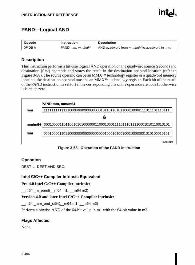
INSTRUCTION SET REFERENCE
emoryresultrwise
PAND—Logical AND
Description
This instruction performs a bitwise logical AND operation on the quadword source (second) anddestination (first) operands and stores the result in the destination operand location (refer toFigure 3-58). The source operand can be an MMX™ technology register or a quadword mlocation; the destination operand must be an MMX™ technology register. Each bit of the of the PAND instruction is set to 1 if the corresponding bits of the operands are both 1; otheit is made zero
Operation
DEST ← DEST AND SRC;
Intel C/C++ Compiler Intrinsic Equivalent
Pre-4.0 Intel C/C++ Compiler intrinsic:
__m64 _m_pand(__m64 m1, __m64 m2)
Version 4.0 and later Intel C/C++ Compiler intrinsic:
__m64 _mm_and_si64(__m64 m1, __m64 m2)
Perform a bitwise AND of the 64-bit value in m1 with the 64-bit value in m2.
Flags Affected
None.
Opcode Instruction Description
0F DB /r PAND mm, mm/m64 AND quadword from mm/m64 to quadword in mm.
Figure 3-58. Operation of the PAND Instruction
PAND mm, mm/m64
mm
mm/m64
mm
1111111111111000000000000000010110110101100010000111011101110111
0001000011011001010100000011000100011110111011110001010110010101
0001000011011000000000000000000100010100100010000001010100010101
3006019
&
3-486

INSTRUCTION SET REFERENCE
PAND—Logical AND (Continued)
Protected Mode Exceptions
#GP(0) If a memory operand effective address is outside the CS, DS, ES, FS, orGS segment limit.
#SS(0) If a memory operand effective address is outside the SS segment limit.
#UD If EM in CR0 is set.
#NM If TS in CR0 is set.
#MF If there is a pending FPU exception.
#PF(fault-code) If a page fault occurs.
#AC(0) If alignment checking is enabled and an unaligned memory reference ismade while the current privilege level is 3.
Real-Address Mode Exceptions
#GP If any part of the operand lies outside of the effective address space from0 to FFFFH.
#UD If EM in CR0 is set.
#NM If TS in CR0 is set.
#MF If there is a pending FPU exception.
Virtual-8086 Mode Exceptions
#GP If any part of the operand lies outside of the effective address space from0 to FFFFH.
#UD If EM in CR0 is set.
#NM If TS in CR0 is set.
#MF If there is a pending FPU exception.
#PF(fault-code) If a page fault occurs.
#AC(0) If alignment checking is enabled and an unaligned memory reference ismade.
3-487
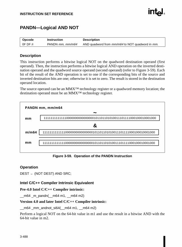
INSTRUCTION SET REFERENCE
n; the
the
PANDN—Logical AND NOT
Description
This instruction performs a bitwise logical NOT on the quadword destination operand (firstoperand). Then, the instruction performs a bitwise logical AND operation on the inverted desti-nation operand and the quadword source operand (second operand) (refer to Figure 3-59). Eachbit of the result of the AND operation is set to one if the corresponding bits of the source andinverted destination bits are one; otherwise it is set to zero. The result is stored in the destinationoperand location.
The source operand can be an MMX™ technology register or a quadword memory locatiodestination operand must be an MMX™ technology register.
Operation
DEST ← (NOT DEST) AND SRC;
Intel C/C++ Compiler Intrinsic Equivalent
Pre-4.0 Intel C/C++ Compiler intrinsic:
__m64 _m_pandn(__m64 m1, __m64 m2)
Version 4.0 and later Intel C/C++ Compiler intrinsic:
__m64 _mm_andnot_si64(__m64 m1, __m64 m2)
Perform a logical NOT on the 64-bit value in m1 and use the result in a bitwise AND with64-bit value in m2.
Opcode Instruction Description
0F DF /r PANDN mm, mm/m64 AND quadword from mm/m64 to NOT quadword in mm.
Figure 3-59. Operation of the PANDN Instruction
~
&m/m64
mm
mm 11111111111110000000000000000101101101010011101111000100010001000
11111111111110000000000000000101101101010011101111000100010001000
11111111111110000000000000000101101101010011101111000100010001000
PANDN mm, mm/m64
3-488

INSTRUCTION SET REFERENCE
PANDN—Logical AND NOT (Continued)
Flags Affected
None.
Protected Mode Exceptions
#GP(0) If a memory operand effective address is outside the CS, DS, ES, FS, orGS segment limit.
#SS(0) If a memory operand effective address is outside the SS segment limit.
#UD If EM in CR0 is set.
#NM If TS in CR0 is set.
#MF If there is a pending FPU exception.
#PF(fault-code) If a page fault occurs.
#AC(0) If alignment checking is enabled and an unaligned memory reference ismade while the current privilege level is 3.
Real-Address Mode Exceptions
#GP If any part of the operand lies outside of the effective address space from0 to FFFFH.
#UD If EM in CR0 is set.
#NM If TS in CR0 is set.
#MF If there is a pending FPU exception.
Virtual-8086 Mode Exceptions
#GP If any part of the operand lies outside of the effective address space from0 to FFFFH.
#UD If EM in CR0 is set.
#NM If TS in CR0 is set.
#MF If there is a pending FPU exception.
#PF(fault-code) If a page fault occurs.
#AC(0) If alignment checking is enabled and an unaligned memory reference ismade.
3-489

INSTRUCTION SET REFERENCE
r be an
oper-
PAVGB/PAVGW—Packed Average
Description
The PAVG instructions add the unsigned data elements of the source operand to the unsigneddata elements of the destination register, along with a carry-in. The results of the add are theneach independently right-shifted by one bit position. The high order bits of each element arefilled with the carry bits of the corresponding sum.
The destination operand is an MMX™ technology register. The source operand can eitheMMX™ technology register or a 64-bit memory operand.
The PAVGB instruction operates on packed unsigned bytes, and the PAVGW instructionates on packed unsigned words.
Figure 3-60. Operation of the PAVGB/PAVGW Instruction
Opcode Instruction Description
0F,E0, /r PAVGB mm1,mm2/m64 Average with rounding packed unsigned bytes from MM2/Mem to packed bytes in MM1 register.
0F,E3, /r PAVGW mm1, mm2/m64 Average with rounding packed unsigned words from MM2/Mem to packed words in MM1 register.
255
PAVGB mm1,mm2/m64
01 253 254 255 1 0
255 01 255 255 255 1 0
255 02 254 255 255 2 0
= = = == = = =mm1
mm1
mm2/64
3-490

INSTRUCTION SET REFERENCE
PAVGB/PAVGW—Packed Average (Continued)
Operation
IF (* instruction = PAVGB *) THENX[0] = DEST[7-0];Y[0] = SRC/m64[7-0];X[1] = DEST[15-8];Y[1] = SRC/m64[15-8];X[2] = DEST[23-16];Y[2] = SRC/m64[23-16];X[3] = DEST[31-24];Y[3] = SRC/m64[31-24];X[4] = DEST[39-32];Y[4] = SRC/m64[39-32];X[5] = DEST[47-40];Y[5] = SRC/m64[47-40];X[6] = DEST[55-48];Y[6] = SRC/m64[55-48];X[7] = DEST[63-56];Y[7] = SRC/m64[63-56];
WHILE (I < 8)TEMP[I] = ZERO_EXT(X[I], 8) + ZERO_EXT{Y[I], 8);RES[I] = (TEMP[I] + 1) >> 1;
ENDWHILE
DEST[7-0] = RES[0];DEST[15-8] = RES[1];DEST[23-16] = RES[2];DEST[31-24] = RES[3];DEST[39-32] = RES[4];DEST[47-40] = RES[5];DEST[55-48] = RES[6];DEST[63-56] = RES[7];
ELSE IF (* instruction PAVGW *)THENX[0] = DEST[15-0];Y[0] = SRC/m64[15-0];X[1] = DEST[31-16];Y[1] = SRC/m64[31-16];X[2] = DEST[47-32];Y[2] = SRC/m64[47-32];X[3] = DEST[63-48];Y[3] = SRC/m64[63-48];
3-491

INSTRUCTION SET REFERENCE
PAVGB/PAVGW—Packed Average (Continued)
WHILE (I < 4)TEMP[I] = ZERO_EXT(X[I], 16) + ZERO_EXT{Y[I], 16);RES[I] = (TEMP[I] + 1) >> 1;
ENDWHILE
DEST[15-0] = RES[0];DEST[31-16] = RES[1];DEST[47-32] = RES[2];DEST[63-48] = RES[3];
FI;
Intel C/C++ Compiler Intrinsic Equivalent
Pre-4.0 Intel C/C++ Compiler intrinsic:
__m64_mm_pavgb(__m64 a, __m64 b)
Pre-4.0 Intel C/C++ Compiler intrinsic:
__m64_mm_avg_pu8(__m64 a, __m64 b)
Performs the packed average on the eight 8-bit values of the two operands.
Pre-4.0 Intel C/C++ Compiler intrinsic:
__m64_mm_pavgw(__m64 a, __m64 b)
Pre-4.0 Intel C/C++ Compiler intrinsic:
__m64_mm_avg_pu16(__m64 a, __m64 b)
Performs the packed average on the four 16-bit values of the two operands.
Numeric Exceptions
None.
3-492

INSTRUCTION SET REFERENCE
PAVGB/PAVGW—Packed Average (Continued)
Protected Mode Exceptions
#GP(0) For an illegal memory operand effective address in the CS, DS, ES, FS, orGS segments.
#SS(0) For an illegal address in the SS segment.
#PF(fault-code) For a page fault.
#UD If CR0.EM = 1.
#NM If TS bit in CR0 is set.
#MF If there is a pending FPU exception.
#AC For unaligned memory reference. To enable #AC exceptions, three condi-tions must be true(CR0.AM is set; EFLAGS.AC is set; current CPL is 3).
Real Address Mode Exceptions
Interrupt 13 If any part of the operand would lie outside of the effective address spacefrom 0 to 0FFFFH.
#UD If CR0.EM = 1.
#NM If TS bit in CR0 is set.
#MF If there is a pending FPU exception.
Virtual 8086 Mode Exceptions
Same exceptions as in Real Address Mode.
#PF(fault-code) For a page fault.
#AC For unaligned memory references (if the current privilege level is 3).
3-493

INSTRUCTION SET REFERENCE
either
ondingg to the
ondinging to
corre-erand
PCMPEQB/PCMPEQW/PCMPEQD—Packed Compare for Equal
Description
These instructions compare the individual data elements (bytes, words, or doublewords) in thedestination operand (first operand) to the corresponding data elements in the source operand(second operand) (refer to Figure 3-61). If a pair of data elements are equal, the correspondingdata element in the destination operand is set to all ones; otherwise, it is set to all zeroes. Thedestination operand must be an MMX™ technology register; the source operand may bean MMX™ technology register or a 64-bit memory location.
The PCMPEQB instruction compares the bytes in the destination operand to the correspbytes in the source operand, with the bytes in the destination operand being set accordinresults.
The PCMPEQW instruction compares the words in the destination operand to the correspwords in the source operand, with the words in the destination operand being set accordthe results.
The PCMPEQD instruction compares the doublewords in the destination operand to thesponding doublewords in the source operand, with the doublewords in the destination opbeing set according to the results.
Opcode Instruction Description
0F 74 /r PCMPEQB mm, mm/m64 Compare packed bytes in mm/m64 with packed bytes in mm for equality.
0F 75 /r PCMPEQW mm, mm/m64 Compare packed words in mm/m64 with packed words in mm for equality.
0F 76 /r PCMPEQD mm, mm/m64 Compare packed doublewords in mm/m64 with packed doublewords in mm for equality.
Figure 3-61. Operation of the PCMPEQW Instruction
PCMPEQW mm, mm/m64
mm
mm/m64
mm
0000000000000000
0000000000000000
1111111111111111
0000000000000001
0000000000000000
0000000000000000
0000000000000111
0111000111000111
0000000000000000
0111000111000111
0111000111000111
1111111111111111
True TrueFalse False
3006020
== ==== ==
3-494

INSTRUCTION SET REFERENCE
PCMPEQB/PCMPEQW/PCMPEQD—Packed Compare for Equal (Continued)
Operation
IF instruction is PCMPEQBTHEN
IF DEST(7..0) = SRC(7..0)THEN DEST(7 0) ← FFH; ELSE DEST(7..0) ← 0;
* Continue comparison of second through seventh bytes in DEST and SRC *IF DEST(63..56) = SRC(63..56)
THEN DEST(63..56) ← FFH;ELSE DEST(63..56) ← 0;
ELSE IF instruction is PCMPEQWTHEN
IF DEST(15..0) = SRC(15..0) THEN DEST(15..0) ← FFFFH;ELSE DEST(15..0) ← 0;
* Continue comparison of second and third words in DEST and SRC *IF DEST(63..48) = SRC(63..48)
THEN DEST(63..48) ← FFFFH;ELSE DEST(63..48) ← 0;
ELSE (* instruction is PCMPEQD *)IF DEST(31..0) = SRC(31..0)
THEN DEST(31..0) ← FFFFFFFFH; ELSE DEST(31..0) ← 0;
IF DEST(63..32) = SRC(63..32)THEN DEST(63..32) ← FFFFFFFFH;ELSE DEST(63..32) ← 0;
FI;
3-495

INSTRUCTION SET REFERENCE
PCMPEQB/PCMPEQW/PCMPEQD—Packed Compare for Equal (Continued)
Intel C/C++ Compiler Intrinsic Equivalents
Pre-4.0 Intel C/C++ Compiler intrinsic:
__m64 _m_pcmpeqb (__m64 m1, __m64 m2)
Version 4.0 and later Intel C/C++ Compiler intrinsic:
__m64 _mm_cmpeq_pi8 (__m64 m1, __m64 m2)
If the respective 8-bit values in m1 are equal to the respective 8-bit values in m2 set the respec-tive 8-bit resulting values to all ones, otherwise set them to all zeroes.
Pre-4.0 Intel C/C++ Compiler intrinsic:
__m64 _m_pcmpeqw (__m64 m1, __m64 m2)
Version 4.0 and later Intel C/C++ Compiler intrinsic:
__m64 _mm_cmpeq_pi16 (__m64 m1, __m64 m2)
If the respective 16-bit values in m1 are equal to the respective 16-bit values in m2 set therespective 16-bit resulting values to all ones, otherwise set them to all zeroes.
Pre-4.0 Intel C/C++ Compiler intrinsic:
__m64 _m_pcmpeqd (__m64 m1, __m64 m2)
Version 4.0 and later Intel C/C++ Compiler intrinsic:
__m64 _mm_cmpeq_pi32 (__m64 m1, __m64 m2)
If the respective 32-bit values in m1 are equal to the respective 32-bit values in m2 set therespective 32-bit resulting values to all ones, otherwise set them to all zeroes.
Flags Affected
None:
3-496
INSTRUCTION SET REFERENCE
PCMPEQB/PCMPEQW/PCMPEQD—Packed Compare for Equal (Continued)
Protected Mode Exceptions
#GP(0) If a memory operand effective address is outside the CS, DS, ES, FS, orGS segment limit.
#SS(0) If a memory operand effective address is outside the SS segment limit.
#UD If EM in CR0 is set.
#NM If TS in CR0 is set.
#MF If there is a pending FPU exception.
#PF(fault-code) If a page fault occurs.
#AC(0) If alignment checking is enabled and an unaligned memory reference ismade while the current privilege level is 3.
Real-Address Mode Exceptions
#GP If any part of the operand lies outside of the effective address space from0 to FFFFH.
#UD If EM in CR0 is set.
#NM If TS in CR0 is set.
#MF If there is a pending FPU exception.
Virtual-8086 Mode Exceptions
#GP If any part of the operand lies outside of the effective address space from0 to FFFFH.
#UD If EM in CR0 is set.
#NM If TS in CR0 is set.
#MF If there is a pending FPU exception.
#PF(fault-code) If a page fault occurs.
#AC(0) If alignment checking is enabled and an unaligned memory reference ismade.
3-497

INSTRUCTION SET REFERENCE
logy
corre-ing set
corre- being
to theestina-
PCMPGTB/PCMPGTW/PCMPGTD—Packed Compare for Greater Than
Description
These instructions compare the individual signed data elements (bytes, words, or doublewords)in the destination operand (first operand) to the corresponding signed data elements in the sourceoperand (second operand) (refer to Figure 3-62). If a data element in the destination operand isgreater than its corresponding data element in the source operand, the data element in the desti-nation operand is set to all ones; otherwise, it is set to all zeroes. The destination operand mustbe an MMX™ technology register; the source operand may be either an MMX™ technoregister or a 64-bit memory location.
The PCMPGTB instruction compares the signed bytes in the destination operand to thesponding signed bytes in the source operand, with the bytes in the destination operand beaccording to the results.
The PCMPGTW instruction compares the signed words in the destination operand to thesponding signed words in the source operand, with the words in the destination operandset according to the results.
The PCMPGTD instruction compares the signed doublewords in the destination operandcorresponding signed doublewords in the source operand, with the doublewords in the dtion operand being set according to the results.
Opcode Instruction Description
0F 64 /r PCMPGTB mm, mm/m64
Compare packed bytes in mm with packed bytes in mm/m64 for greater value.
0F 65 /r PCMPGTW mm, mm/m64
Compare packed words in mm with packed words in mm/m64 for greater value.
0F 66 /r PCMPGTD mm, mm/m64
Compare packed doublewords in mm with packed doublewords in mm/m64 for greater value.
Figure 3-62. Operation of the PCMPGTW Instruction
PCMPGTW mm, mm/m64
mm
mm/m64
mm
0000000000000000
0000000000000000
0000000000000000
0000000000000001
0000000000000000
1111111111111111
0000000000000111
0111000111000111
0000000000000000
0111000111000111
0111000111000111
0000000000000000
False FalseTrue False
3006021
> >> >
3-498

INSTRUCTION SET REFERENCE
PCMPGTB/PCMPGTW/PCMPGTD—Packed Compare for Greater Than (Continued)
Operation
IF instruction is PCMPGTB THEN
IF DEST(7..0) > SRC(7..0)THEN DEST(7 0) ← FFH; ELSE DEST(7..0) ← 0;
* Continue comparison of second through seventh bytes in DEST and SRC *IF DEST(63..56) > SRC(63..56)
THEN DEST(63..56) ← FFH;ELSE DEST(63..56) ← 0;
ELSE IF instruction is PCMPGTWTHEN
IF DEST(15..0) > SRC(15..0)THEN DEST(15..0) ← FFFFH;ELSE DEST(15..0) ←0;
* Continue comparison of second and third bytes in DEST and SRC *IF DEST(63..48) > SRC(63..48)
THEN DEST(63..48) ← FFFFH;ELSE DEST(63..48) ← 0;
ELSE { (* instruction is PCMPGTD *)IF DEST(31..0) > SRC(31..0)
THEN DEST(31..0) ← FFFFFFFFH; ELSE DEST(31..0) ← 0;
IF DEST(63..32) > SRC(63..32)THEN DEST(63..32) ← FFFFFFFFH;ELSE DEST(63..32) ← 0;
FI;
3-499

INSTRUCTION SET REFERENCE
PCMPGTB/PCMPGTW/PCMPGTD—Packed Compare for Greater Than (Continued)
Intel C/C++ Compiler Intrinsic Equivalents
Pre-4.0 Intel C/C++ Compiler intrinsic:
__m64 _m_pcmpgtb (__m64 m1, __m64 m2)
Version 4.0 and later Intel C/C++ Compiler intrinsic:
__m64 _mm_cmpgt_pi8 (__m64 m1, __m64 m2)
If the respective 8-bit values in m1 are greater than the respective 8-bit values in m2 set therespective 8-bit resulting values to all ones, otherwise set them to all zeroes.
Pre-4.0 Intel C/C++ Compiler intrinsic:
__m64 _m_pcmpgtw (__m64 m1, __m64 m2)
Version 4.0 and later Intel C/C++ Compiler intrinsic:
__m64 _mm_pcmpgt_pi16 (__m64 m1, __m64 m2)
If the respective 16-bit values in m1 are greater than the respective 16-bit values in m2 set therespective 16-bit resulting values to all ones, otherwise set them to all zeroes.
Pre-4.0 Intel C/C++ Compiler intrinsic:
__m64 _m_pcmpgtd (__m64 m1, __m64 m2)
Version 4.0 and later Intel C/C++ Compiler intrinsic:
__m64 _mm_pcmpgt_pi32 (__m64 m1, __m64 m2)
If the respective 32-bit values in m1 are greater than the respective 32-bit values in m2 set therespective 32-bit resulting values to all ones, otherwise set them all to zeroes.
Flags Affected
None.
3-500

INSTRUCTION SET REFERENCE
PCMPGTB/PCMPGTW/PCMPGTD—Packed Compare for Greater Than (Continued)
Protected Mode Exceptions
#GP(0) If a memory operand effective address is outside the CS, DS, ES, FS, orGS segment limit.
#SS(0) If a memory operand effective address is outside the SS segment limit.
#UD If EM in CR0 is set.
#NM If TS in CR0 is set.
#MF If there is a pending FPU exception.
#PF(fault-code) If a page fault occurs.
#AC(0) If alignment checking is enabled and an unaligned memory reference ismade while the current privilege level is 3.
Real-Address Mode Exceptions
#GP If any part of the operand lies outside of the effective address space from0 to FFFFH.
#UD If EM in CR0 is set.
#NM If TS in CR0 is set.
#MF If there is a pending FPU exception.
Virtual-8086 Mode Exceptions
#GP If any part of the operand lies outside of the effective address space from0 to FFFFH.
#UD If EM in CR0 is set.
#NM If TS in CR0 is set.
#MF If there is a pending FPU exception.
#PF(fault-code) If a page fault occurs.
#AC(0) If alignment checking is enabled and an unaligned memory reference ismade.
3-501

INSTRUCTION SET REFERENCE
PEXTRW—Extract Word
Description
The PEXTRW instruction moves the word in MM (selected by the two least significant bits ofimm8) to the lower half of a 32-bit integer register.
Figure 3-63. Operation of the PEXTRW Instruction
Operation
SEL = imm8 AND 0X3;MM_TEMP = (SRC >> (SEL * 16)) AND 0XFFFF;r32[15-0] = MM_TEMP[15-0];r32[31-16] = 0X0000;
Intel C/C++ Compiler Intrinsic Equivalent
Pre-4.0 Intel C/C++ Compiler intrinsic:
int_m_pextrw(__m64 a, int n)
Version 4.0 and later Intel C/C++ Compiler intrinsic:
int_mm_extract_pi16(__m64 a, int n)
Extracts one of the four words of a. The selector n must be an immediate.
Opcode Instruction Description
0F,C5, /r, ib PEXTRW r32, mm, imm8 Extract the word pointed to by imm8 from MM and move it to a 32-bit integer register.
PEXTRW r32,mm1,0x09
Mm1
R32
R32= =
3-502

INSTRUCTION SET REFERENCE
PEXTRW—Extract Word (Continued)
Numeric Exceptions
None.
Protected Mode Exceptions
#GP(0) For an illegal memory operand effective address in the CS, DS, ES, FS, orGS segments.
#SS(0) For an illegal address in the SS segment.
#PF(fault-code) For a page fault.
#UD If CR0.EM = 1.
#NM If TS bit in CR0 is set.
#MF If there is a pending FPU exception
Real Address Mode Exceptions
Interrupt 13 If any part of the operand would lie outside of the effective address spacefrom 0 to 0FFFFH.
#UD If CR0.EM = 1.
#NM If TS bit in CR0 is set.
#MF If there is a pending FPU exception.
Virtual 8086 Mode Exceptions
Same exceptions as in Real Address Mode.
#PF(fault-code) For a page fault.
3-503

INSTRUCTION SET REFERENCE
PINSRW—Insert Word
Description
The PINSRW instruction loads a word from the lower half of a 32-bit integer register (or frommemory) and inserts it in the MM destination register, at a position defined by the two leastsignificant bits of the imm8 constant. The insertion is done in such a way that the three otherwords from the destination register are left untouched.
Figure 3-64. Operation of the PINSRW Instruction
Operation
SEL = imm8 AND 0X3;IF(SEL = 0) THEN
MASK=0X000000000000FFFF;ELSE
IF(SEL = 1) THENMASK=0X00000000FFFF0000 :
ELSEIF(SEL = 2) THEN
MASK=0XFFFF000000000000;FI
FIFIDEST = (DEST AND NOT MASK) OR ((m16/r32[15-0] << (SEL * 16)) AND MASK);
Opcode Instruction Description
0F,C4,/r,ib PINSRW mm, r32/m16, imm8
Insert the word from the lower half of r32 or from Mem16 into the position in MM pointed to by imm8 without touching the other words.
Mm1
mm1
PINSRW mm1,r32/m16, 0x0A
0x985F
=0x4326 0x985F
R32/m16
3-504

INSTRUCTION SET REFERENCE
PINSRW—Insert Word (Continued)
Intel C/C++ Compiler Intrinsic Equivalent
Pre-4.0 Intel C/C++ Compiler intrinsic:
__m64 _m_pinsrw(__m64 a, int d, int n)
Version 4.0 and later Intel C/C++ Compiler intrinsic:
__m64 _mm_insert_pi16(__m64 a, int d, int n)
Inserts word d into one of four words of a. The selector n must be an immediate.
Numeric Exceptions
None.
Protected Mode Exceptions
#GP(0) For an illegal memory operand effective address in the CS, DS, ES, FS, orGS segments.
#SS(0) For an illegal address in the SS segment.
#PF (fault-code) For a page fault.
#UD If CR0.EM = 1.
#NM If TS bit in CR0 is set.
#MF If there is a pending FPU exception.
#AC For unaligned memory reference. To enable #AC exceptions, three condi-tions must be true(CR0.AM is set; EFLAGS.AC is set; current CPL is 3)
Real Address Mode Exceptions
Interrupt 13 If any part of the operand would lie outside of the effective address spacefrom 0 to 0FFFFH.
#UD If CR0.EM = 1.
#NM If TS bit in CR0 is set.
#MF If there is a pending FPU exception.
Virtual 8086 Mode Exceptions
Same exceptions as in Real Address Mode.
#AC For unaligned memory reference if the current privilege level is 3.
#PF (fault-code) For a page fault.
3-505

INSTRUCTION SET REFERENCE
tech-64-bit
the
PMADDWD—Packed Multiply and Add
Description
This instruction multiplies the individual signed words of the destination operand by the corre-sponding signed words of the source operand, producing four signed, doubleword results (referto Figure 3-65). The two doubleword results from the multiplication of the high-order words areadded together and stored in the upper doubleword of the destination operand; the two double-word results from the multiplication of the low-order words are added together and stored in thelower doubleword of the destination operand. The destination operand must be an MMX™nology register; the source operand may be either an MMX™ technology register or a memory location.
The PMADDWD instruction wraps around to 80000000H only when all four words of bothsource and destination operands are 8000H.
Operation
DEST(31..0) ← (DEST(15..0) ∗ SRC(15..0)) + (DEST(31..16) ∗ SRC(31..16));DEST(63..32) ← (DEST(47..32) ∗ SRC(47..32)) + (DEST(63..48) ∗ SRC(63..48));
Opcode Instruction Description
0F F5 /r PMADDWD mm, mm/m64
Multiply the packed words in mm by the packed words in mm/m64. Add the 32-bit pairs of results and store in mm as doubleword
Figure 3-65. Operation of the PMADDWD Instruction
∗ ∗ ∗∗01110001110001110111000111000111
1000000000000000 0000010000000000
1100100011100011 1001110000000000
+ +mm
PMADDWD mm, mm/m64
mm/m64
mm
3-506

INSTRUCTION SET REFERENCE
PMADDWD—Packed Multiply and Add (Continued)
Intel C/C++ Compiler Intrinsic Equivalent
Pre-4.0 Intel C/C++ Compiler intrinsic:
__m64 _m_pmaddwd(__m64 m1, __m64 m2)
Version 4.0 and later Intel C/C++ Compiler intrinsic:
__m64 _mm_madd_pi16(__m64 m1, __m64 m2)
Multiply four 16-bit values in m1 by four 16-bit values in m2 producing four 32-bit intermediateresults, which are then summed by pairs to produce two 32-bit results.
Flags Affected
None.
Protected Mode Exceptions
#GP(0) If a memory operand effective address is outside the CS, DS, ES, FS, orGS segment limit.
#SS(0) If a memory operand effective address is outside the SS segment limit.
#UD If EM in CR0 is set.
#NM If TS in CR0 is set.
#MF If there is a pending FPU exception.
#PF(fault-code) If a page fault occurs.
#AC(0) If alignment checking is enabled and an unaligned memory reference ismade while the current privilege level is 3.
Real-Address Mode Exceptions
#GP If any part of the operand lies outside of the effective address space from0 to FFFFH.
#UD If EM in CR0 is set.
#NM If TS in CR0 is set.
#MF If there is a pending FPU exception.
3-507

INSTRUCTION SET REFERENCE
PMADDWD—Packed Multiply and Add (Continued)
Virtual-8086 Mode Exceptions
#GP If any part of the operand lies outside of the effective address space from0 to FFFFH.
#UD If EM in CR0 is set.
#NM If TS in CR0 is set.
#MF If there is a pending FPU exception.
#PF(fault-code) If a page fault occurs.
#AC(0) If alignment checking is enabled and an unaligned memory reference ismade.
3-508

INSTRUCTION SET REFERENCE
PMAXSW—Packed Signed Integer Word Maximum
Description
The PMAXSW instruction returns the maximum between the four signed words in MM1 andMM2/Mem.
Figure 3-66. Operation of the PMAXSW Instruction
Opcode Instruction Description
0F,EE, /r PMAXSW mm1, mm2/m64 Return the maximum words between MM2/Mem and MM1.
mm1
mm2/m64
mm1
= = = =
3-509

INSTRUCTION SET REFERENCE
PMAXSW—Packed Signed Integer Word Maximum (Continued)
Operation
IF DEST[15-0] > SRC/m64[15-0]) THEN(DEST[15-0] = DEST[15-0];
ELSE(DEST[15-0] = SRC/m64[15-0];
FIIF DEST[31-16] > SRC/m64[31-16]) THEN
(DEST[31-16] = DEST[31-16];ELSE
(DEST[31-16] = SRC/m64[31-16];FIIF DEST[47-32] > SRC/m64[47-32]) THEN
(DEST[47-32] = DEST[47-32];ELSE
(DEST[47-32] SRC/m64[47-32];FIIF DEST[63-48] > SRC/m64[63-48]) THEN
(DEST[63-48] = DEST[63-48];ELSE
(DEST[63-48] = SRC/m64[63-48];FI
Intel C/C++ Compiler Intrinsic Equivalent
Pre-4.0 Intel C/C++ Compiler intrinsic:
__m64 _m_pmaxsw(__m64 a, __m64 b)
Version 4.0 and later Intel C/C++ Compiler intrinsic:
__m64 _mm_max_pi16(__m64 a, __m64 b)
Computes the element-wise maximum of the words in a and b.
Numeric Exceptions
None.
3-510

INSTRUCTION SET REFERENCE
PMAXSW—Packed Signed Integer Word Maximum (Continued)
Protected Mode Exceptions
#GP(0) For an illegal memory operand effective address in the CS, DS, ES, FS, orGS segments.
#SS(0) For an illegal address in the SS segment.
#PF (fault-code) For a page fault.
#UD If CR0.EM = 1.
#NM If TS bit in CR0 is set.
#MF If there is a pending FPU exception.
#AC For unaligned memory reference. To enable #AC exceptions, three condi-tions must be true(CR0.AM is set; EFLAGS.AC is set; current CPL is 3)
Real Address Mode Exceptions
Interrupt 13 If any part of the operand would lie outside of the effective address spacefrom 0 to 0FFFFH.
#UD If CR0.EM = 1.
#NM If TS bit in CR0 is set.
#MF If there is a pending FPU exception.
Virtual 8086 Mode Exceptions
Same exceptions as in Real Address Mode.
#PF(fault-code) For a page fault.
#AC For unaligned memory reference if the current privilege level is 3.
3-511

INSTRUCTION SET REFERENCE
PMAXUB—Packed Unsigned Integer Byte Maximum
Description
The PMAXUB instruction returns the maximum between the eight unsigned words in MM1 andMM2/Mem.
Figure 3-67. Operation of the PMAXUB Instruction
Opcode Instruction Description
0F,DE, /r PMAXUB mm1, mm2/m64 Return the maximum bytes between MM2/Mem and MM1.
59
PMAXUB mm1, mm2/m64
4046 87 187 55 221 27
24 1165 101 78 207 111 36
59 4065 101 187 207 221 36
= = = == = = =mm1
mm1
mm2/m64
3-512

INSTRUCTION SET REFERENCE
PMAXUB—Packed Unsigned Integer Byte Maximum (Continued)
Operation
IF DEST[7-0] > SRC/m64[7-0]) THEN(DEST[7-0] = DEST[7-0];
ELSE(DEST[7-0] = SRC/m64[7-0];
FIIF DEST[15-8] > SRC/m64[15-8]) THEN
(DEST[15-8] = DEST[15-8];ELSE
(DEST[15-8] = SRC/m64[15-8];FIIF DEST[23-16] > SRC/m64[23-16]) THEN
(DEST[23-16] = DEST[23-16];ELSE
(DEST[23-16] = SRC/m64[23-16];FIIF DEST[31-24] > SRC/m64[31-24]) THEN
(DEST[31-24] = DEST[31-24];ELSE
(DEST[31-24] = SRC/m64[31-24];FIIF DEST[39-32] > SRC/m64[39-32]) THEN
(DEST[39-32] = DEST[39-32];ELSE
(DEST[39-32] = SRC/m64[39-32];FIIF DEST[47-40] > SRC/m64[47-40]) THEN
(DEST[47-40] = DEST[47-40];ELSE
(DEST[47-40] = SRC/m64[47-40];FIIF DEST[55-48] > SRC/m64[55-48]) THEN
(DEST[55-48] = DEST[55-48];ELSE
(DEST[55-48] = SRC/m64[55-48];FIIF DEST[63-56] > SRC/m64[63-56]) THEN
(DEST[63-56] = DEST[63-56];ELSE
(DEST[63-56] = SRC/m64[63-56];FI
3-513

INSTRUCTION SET REFERENCE
PMAXUB—Packed Unsigned Integer Byte Maximum (Continued)
Intel C/C++ Compiler Intrinsic Equivalent
Pre-4.0 Intel C/C++ Compiler intrinsic:
__m64 _m_pmaxub(__m64 a, __m64 b)
Version 4.0 and later Intel C/C++ Compiler intrinsic:
__m64 _mm_max_pu8(__m64 a, __m64 b)
Computes the element-wise maximum of the unsigned bytes in a and b.
Numeric Exceptions
None.
Protected Mode Exceptions
#GP(0) For an illegal memory operand effective address in the CS, DS, ES, FS, orGS segments.
#SS(0) For an illegal address in the SS segment.
#PF (fault-code) For a page fault.
#UD If CR0.EM = 1.
#NM If TS bit in CR0 is set.
#MF If there is a pending FPU exception.
#AC For unaligned memory reference. To enable #AC exceptions, three condi-tions must be true(CR0.AM is set; EFLAGS.AC is set; current CPL is 3)
Real Address Mode Exceptions
Interrupt 13 If any part of the operand would lie outside of the effective address spacefrom 0 to 0FFFFH.
#UD If CR0.EM = 1.
#NM If TS bit in CR0 is set.
#MF If there is a pending FPU exception
Virtual 8086 Mode Exceptions
Same exceptions as in Real Address Mode.
#PF(fault-code) For a page fault.
#AC For unaligned memory reference if the current privilege level is 3.
3-514

INSTRUCTION SET REFERENCE
PMINSW—Packed Signed Integer Word Minimum
Description
The PMINSW instruction returns the minimum between the four signed words in MM1 andMM2/Mem.
Figure 3-68. Operation of the PMINSW Instruction
Opcode Instruction Description
0F,EA, /r PMINSW mm1, mm2/m64 Return the minimum words between MM2/Mem and MM1.
mm1
mm2/m64
mm1
= = = =
3-515

INSTRUCTION SET REFERENCE
PMINSW—Packed Signed Integer Word Minimum (Continued)
Operation
IF DEST[15-0] < SRC/m64[15-0]) THEN(DEST[15-0] = DEST[15-0];
ELSE(DEST[15-0] = SRC/m64[15-0];
FIIF DEST[31-16] < SRC/m64[31-16]) THEN
(DEST[31-16] = DEST[31-16];ELSE
(DEST[31-16] = SRC/m64[31-16];FIIF DEST[47-32] < SRC/m64[47-32]) THEN
(DEST[47-32] = DEST[47-32];ELSE
(DEST[47-32] SRC/m64[47-32];FIIF DEST[63-48] < SRC/m64[63-48]) THEN
(DEST[63-48] = DEST[63-48];ELSE
(DEST[63-48] = SRC/m64[63-48];FI
Intel C/C++ Compiler Intrinsic Equivalent
Pre-4.0 Intel C/C++ Compiler intrinsic:
__m64 _m_pminsw(__m64 a, __m64 b)
Version 4.0 and later Intel C/C++ Compiler intrinsic:
__m64 _mm_min_pi16(__m64 a, __m64 b)
Computes the element-wise minimum of the words in a and b.
Numeric Exceptions
None.
3-516

INSTRUCTION SET REFERENCE
PMINSW—Packed Signed Integer Word Minimum (Continued)
Protected Mode Exceptions
#GP(0) For an illegal memory operand effective address in the CS, DS, ES, FS, orGS segments.
#SS(0) For an illegal address in the SS segment.
#PF (fault-code) For a page fault.
#UD If CR0.EM = 1.
#NM If TS bit in CR0 is set.
#MF If there is a pending FPU exception.
#AC For unaligned memory reference. To enable #AC exceptions, three condi-tions must be true(CR0.AM is set; EFLAGS.AC is set; current CPL is 3)
Real Address Mode Exceptions
Interrupt 13 If any part of the operand would lie outside of the effective address spacefrom 0 to 0FFFFH.
#UD If CR0.EM = 1.
#NM If TS bit in CR0 is set.
#MF If there is a pending FPU exception.
Virtual 8086 Mode Exceptions
Same exceptions as in Real Address Mode.
#PF(fault-code) For a page fault.
#AC For unaligned memory reference if the current privilege level is 3.
3-517

INSTRUCTION SET REFERENCE
PMINUB—Packed Unsigned Integer Byte Minimum
Description
The PMINUB instruction returns the minimum between the eight unsigned words in MM1 andMM2/Mem.
Figure 3-69. Operation of the PMINUB Instruction
Opcode Instruction Description
0F,DA, /r PMINUB mm1, mm2/m64 Return the minimum bytes between MM2/Mem and MM1.
59
PMINUB mm1, mm2/m64
4046 87 187 55 221 27
24 1165 101 78 207 111 36
24 1146 87 78 55 111 27
= = = == = = =mm1
mm1
mm2/m64
3-518

INSTRUCTION SET REFERENCE
PMINUB—Packed Unsigned Integer Byte Minimum (Continued)
Operation
IF DEST[7-0] < SRC/m64[7-0]) THEN(DEST[7-0] = DEST[7-0];
ELSE(DEST[7-0] = SRC/m64[7-0];
FIIF DEST[15-8] < SRC/m64[15-8]) THEN
(DEST[15-8] = DEST[15-8];ELSE
(DEST[15-8] = SRC/m64[15-8];FIIF DEST[23-16] < SRC/m64[23-16]) THEN
(DEST[23-16] = DEST[23-16];ELSE
(DEST[23-16] = SRC/m64[23-16];FIIF DEST[31-24] < SRC/m64[31-24]) THEN
(DEST[31-24] = DEST[31-24];ELSE
(DEST[31-24] = SRC/m64[31-24];FIIF DEST[39-32] < SRC/m64[39-32]) THEN
(DEST[39-32] = DEST[39-32];ELSE
(DEST[39-32] = SRC/m64[39-32];FIIF DEST[47-40] < SRC/m64[47-40]) THEN
(DEST[47-40] = DEST[47-40];ELSE
(DEST[47-40] = SRC/m64[47-40];FIIF DEST[55-48] < SRC/m64[55-48]) THEN
(DEST[55-48] = DEST[55-48];ELSE
(DEST[55-48] = SRC/m64[55-48];FIIF DEST[63-56] < SRC/m64[63-56]) THEN
(DEST[63-56] = DEST[63-56];ELSE
(DEST[63-56] = SRC/m64[63-56];FI
3-519

INSTRUCTION SET REFERENCE
PMINUB—Packed Unsigned Integer Byte Minimum (Continued)
Intel C/C++ Compiler Intrinsic Equivalent
Pre-4.0 Intel C/C++ Compiler intrinsic:
__m64 _m_pminub(__m64 a, __m64 b)
Version 4.0 and later Intel C/C++ Compiler intrinsic:
__m64 _m_min_pu8(__m64 a, __m64 b)
Computes the element-wise minimum of the unsigned bytes in a and b.
Numeric Exceptions
None.
Protected Mode Exceptions
#GP(0) For an illegal memory operand effective address in the CS, DS, ES, FS, orGS segments.
#SS(0) For an illegal address in the SS segment.
#PF (fault-code) For a page fault.
#UD If CR0.EM = 1.
#NM If TS bit in CR0 is set.
#MF If there is a pending FPU exception.
#AC For unaligned memory reference. To enable #AC exceptions, three condi-tions must be true(CR0.AM is set; EFLAGS.AC is set; current CPL is 3).
Real Address Mode Exceptions
Interrupt 13 If any part of the operand would lie outside of the effective address spacefrom 0 to 0FFFFH.
#UD If CR0.EM = 1.
#NM If TS bit in CR0 is set.
#MF If there is a pending FPU exception.
Virtual 8086 Mode Exceptions
Same exceptions as in Real Address Mode.
#PF(fault-code) For a page fault.
#AC For unaligned memory reference if the current privilege level is 3.
3-520

INSTRUCTION SET REFERENCE
PMOVMSKB—Move Byte Mask To Integer
Description
The PMOVMSKB instruction returns an 8-bit mask formed of the most significant bits of eachbyte of its source operand.
Figure 3-70. Operation of the PMOVMSKB Instruction
Operation
r32[7] = SRC[63]; r32[6] = SRC[55];r32[5] = SRC[47]; r32[4] = SRC[39];r32[3] = SRC[31]; r32[2] = SRC[23];r32[1] = SRC[15]; r32[0] = SRC[7];r32[31-8] = 0X000000;
Intel C/C++ Compiler Intrinsic Equivalent
Pre-4.0 Intel C/C++ Compiler intrinsic:
int_m_pmovmskb(__m64 a)
Version 4.0 and later Intel C/C++ Compiler intrinsic:
int_mm_movemask_pi8(__m64 a)
Creates an 8-bit mask from the most significant bits of the bytes in a.
Opcode Instruction Description
0F,D7,/r PMOVMSKB r32, mm Move the byte mask of MM to r32.
PMOVMSKB r32, mm1
mm1
R32
R32=
3-521

INSTRUCTION SET REFERENCE
PMOVMSKB—Move Byte Mask To Integer (Continued)
Numeric Exceptions
None.
Protected Mode Exceptions
#GP(0) For an illegal memory operand effective address in the CS, DS, ES, FS, orGS segments.
#SS(0) For an illegal address in the SS segment.
#PF (fault-code) For a page fault.
#UD If CR0.EM = 1.
#NM If TS bit in CR0 is set.
#MF If there is a pending FPU exception.
#AC For unaligned memory reference. To enable #AC exceptions, three condi-tions must be true(CR0.AM is set; EFLAGS.AC is set; current CPL is 3).
Real Address Mode Exceptions
Interrupt 13 If any part of the operand would lie outside of the effective address spacefrom 0 to 0FFFFH.
#UD If CR0.EM = 1.
#NM If TS bit in CR0 is set.
#MF If there is a pending FPU exception.
Virtual 8086 Mode Exceptions
Same exceptions as in Real Address Mode.
#PF (fault-code) For a page fault.
#AC For unaligned memory reference if the current privilege level is 3.
3-522

INSTRUCTION SET REFERENCE
PMULHUW—Packed Multiply High Unsigned
Description
The PMULHUW instruction multiplies the four unsigned words in the destination operand withthe four unsigned words in the source operand. The high-order 16 bits of the 32-bit intermediateresults are written to the destination operand.
Figure 3-71. Operation of the PMULHUW Instruction
Operation
DEST[15-0] = (DEST[15-0] * SRC/m64[15-0])[31-16];DEST[31-16] = (DEST[31-16] * SRC/m64[31-16])[31-16];DEST[47-32] = (DEST[47-32] * SRC/m64[47-32])[31-16];DEST[63-48] = (DEST[63-48] * SRC/m64[63-48])[31-16];
Opcode Instruction Description
0F,E4,/r PMULHUW mm1, mm2/m64 Multiply the packed unsigned words in MM1 register with the packed unsigned words in MM2/Mem, then store the high-order 16 bits of the results in MM1.
mm1
mm2/m64
mm1
= = = =
* * * *
3-523

INSTRUCTION SET REFERENCE
PMULHUW—Packed Multiply High Unsigned (Continued)
Intel C/C++ Compiler Intrinsic Equivalent
Pre-4.0 Intel C/C++ Compiler intrinsic:
__m64 _m_pmulhuw(__m64 a, __m64 b)
Version 4.0 and later Intel C/C++ Compiler intrinsic:
__m64 _mm_mulhi_pu16(__m64 a, __m64 b)
Multiplies the unsigned words in a and b, returning the upper 16 bits of the 32-bit intermediateresults.
Numeric Exceptions
None.
Protected Mode Exceptions
#GP(0) For an illegal memory operand effective address in the CS, DS, ES, FS, orGS segments.
#SS(0) For an illegal address in the SS segment.
#PF (fault-code) For a page fault.
#UD If CR0.EM = 1.
#NM If TS bit in CR0 is set.
#MF If there is a pending FPU exception.
#AC For unaligned memory reference. To enable #AC exceptions, three condi-tions must be true(CR0.AM is set; EFLAGS.AC is set; current CPL is 3).
Real Address Mode Exceptions
Interrupt 13 If any part of the operand would lie outside of the effective address spacefrom 0 to 0FFFFH.
#UD If CR0.EM = 1.
#NM If TS bit in CR0 is set.
#MF If there is a pending FPU exception.
3-524

INSTRUCTION SET REFERENCE
PMULHUW—Packed Multiply High Unsigned (Continued)
Virtual 8086 Mode Exceptions
Same exceptions as in Real Address Mode.
#PF(fault-code) For a page fault.
#AC For unaligned memory reference if the current privilege level is 3.
3-525

INSTRUCTION SET REFERENCE
er an
PMULHW—Packed Multiply High
Description
This instruction multiplies the four signed words of the source operand (second operand) by thefour signed words of the destination operand (first operand), producing four signed, double-word, intermediate results (refer to Figure 3-72). The high-order word of each intermediateresult is then written to its corresponding word location in the destination operand. The destina-tion operand must be an MMX™ technology register; the source operand may be eithMMX™ technology register or a 64-bit memory location.
Operation
DEST(15..0) ← HighOrderWord(DEST(15..0) ∗ SRC(15..0));DEST(31..16) ← HighOrderWord(DEST(31..16) ∗ SRC(31..16));DEST(47..32) ← HighOrderWord(DEST(47..32) ∗ SRC(47..32));DEST(63..48) ← HighOrderWord(DEST(63..48) ∗ SRC(63..48));
Opcode Instruction Description
0F E5 /r PMULHW mm, mm/m64
Multiply the signed packed words in mm by the signed packed words in mm/m64, then store the high-order word of each doubleword result in mm.
Figure 3-72. Operation of the PMULHW Instruction
PMULHW mm, mm/m64
mm
mm/m64
mm
0111000111000111
1000000000000000
1100011100011100
0111000111000111
0000010000000000
0000000111000111
High Order High OrderHigh Order High Order
3006022
* ** *
3-526

INSTRUCTION SET REFERENCE
PMULHW—Packed Multiply High (Continued)
Intel C/C++ Compiler Intrinsic Equivalent
Pre-4.0 Intel C/C++ Compiler intrinsic:
__m64 _m_pmulhw(__m64 m1, __m64 m2)
Pre-4.0 Intel C/C++ Compiler intrinsic:
__m64 _mM_mulhi_pi16(__m64 m1, __m64 m2)
Multiply four signed 16-bit values in m1 by four signed 16-bit values in m2 and produce thehigh 16 bits of the four results.
Flags Affected
None.
Protected Mode Exceptions
#GP(0) If a memory operand effective address is outside the CS, DS, ES, FS, orGS segment limit.
#SS(0) If a memory operand effective address is outside the SS segment limit.
#UD If EM in CR0 is set.
#NM If TS in CR0 is set.
#MF If there is a pending FPU exception.
#PF(fault-code) If a page fault occurs.
#AC(0) If alignment checking is enabled and an unaligned memory reference ismade while the current privilege level is 3.
Real-Address Mode Exceptions
#GP If any part of the operand lies outside of the effective address space from0 to FFFFH.
#UD If EM in CR0 is set.
#NM If TS in CR0 is set.
#MF If there is a pending FPU exception.
3-527

INSTRUCTION SET REFERENCE
PMULHW—Packed Multiply High (Continued)
Virtual-8086 Mode Exceptions
#GP If any part of the operand lies outside of the effective address space from0 to FFFFH.
#UD If EM in CR0 is set.
#NM If TS in CR0 is set.
#MF If there is a pending FPU exception.
#PF(fault-code) If a page fault occurs.
#AC(0) If alignment checking is enabled and an unaligned memory reference ismade.
3-528

INSTRUCTION SET REFERENCE
erand
PMULLW—Packed Multiply Low
Description
This instruction multiplies the four signed or unsigned words of the source operand (secondoperand) with the four signed or unsigned words of the destination operand (first operand),producing four doubleword, intermediate results (refer to Figure 3-73). The low-order word ofeach intermediate result is then written to its corresponding word location in the destinationoperand. The destination operand must be an MMX™ technology register; the source opmay be either an MMX™ technology register or a 64-bit memory location.
Operation
DEST(15..0) ← LowOrderWord(DEST(15..0) ∗ SRC(15..0));DEST(31..16) ← LowOrderWord(DEST(31..16) ∗ SRC(31..16));DEST(47..32) ← LowOrderWord(DEST(47..32) ∗ SRC(47..32));DEST(63..48) ← LowOrderWord(DEST(63..48) ∗ SRC(63..48));
Opcode Instruction Description
0F D5 /r PMULLW mm, mm/m64
Multiply the packed words in mm with the packed words in mm/m64, then store the low-order word of each doubleword result in mm.
Figure 3-73. Operation of the PMULLW Instruction
PMULLW mm, mm/m64
mm
mm/m64
mm
0111000111000111
1000000000000000
1000000000000000
0111000111000111
0000010000000000
0001110000000000
Low Order Low OrderLow Order Low Order
3006025
* ** *
3-529

INSTRUCTION SET REFERENCE
PMULLW—Packed Multiply Low (Continued)
Intel C/C++ Compiler Intrinsic Equivalent
Pre-4.0 Intel C/C++ Compiler intrinsic:
__m64 _m_pmullw(__m64 m1, __m64 m2)
Version 4.0 and later Intel C/C++ Compiler intrinsic:
__m64 _mm_mullo_pi16(__m64 m1, __m64 m2)
Multiply four 16-bit values in m1 by four 16-bit values in m2 and produce the low 16 bits of thefour results.
Flags Affected
None.
Protected Mode Exceptions
#GP(0) If a memory operand effective address is outside the CS, DS, ES, FS, orGS segment limit.
#SS(0) If a memory operand effective address is outside the SS segment limit.
#UD If EM in CR0 is set.
#NM If TS in CR0 is set.
#MF If there is a pending FPU exception.
#PF(fault-code) If a page fault occurs.
#AC(0) If alignment checking is enabled and an unaligned memory reference ismade while the current privilege level is 3.
Real-Address Mode Exceptions
#GP If any part of the operand lies outside of the effective address space from0 to FFFFH.
#UD If EM in CR0 is set.
#NM If TS in CR0 is set.
#MF If there is a pending FPU exception.
3-530

INSTRUCTION SET REFERENCE
PMULLW—Packed Multiply Low (Continued)
Virtual-8086 Mode Exceptions
#GP If any part of the operand lies outside of the effective address space from0 to FFFFH.
#UD If EM in CR0 is set.
#NM If TS in CR0 is set.
#MF If there is a pending FPU exception.
#PF(fault-code) If a page fault occurs.
#AC(0) If alignment checking is enabled and an unaligned memory reference ismade.
3-531

INSTRUCTION SET REFERENCE
egmentample,nter) isB flag and thes the
loadedelector
th that causesction
sing ae corre-eption
register
m the
ory, thee ESPruction,
POP—Pop a Value from the Stack
Description
This instruction loads the value from the top of the stack to the location specified with the desti-nation operand and then increments the stack pointer. The destination operand can be a general-purpose register, memory location, or segment register.
The current operand-size attribute of the stack segment determines the stack pointer size (16 bitsor 32 bits—the source address size), and the operand-size attribute of the current code sdetermines the amount the stack pointer is incremented (two bytes or four bytes). For exif these address- and operand-size attributes are 32, the 32-bit ESP register (stack poiincremented by four and, if they are 16, the 16-bit SP register is incremented by two. (The in the stack segment’s segment descriptor determines the stack’s address-size attribute,D flag in the current code segment’s segment descriptor, along with prefixes, determineoperand-size attribute and also the address-size attribute of the destination operand.)
If the destination operand is one of the segment registers DS, ES, FS, GS, or SS, the valueinto the register must be a valid segment selector. In protected mode, popping a segment sinto a segment register automatically causes the descriptor information associated wisegment selector to be loaded into the hidden (shadow) part of the segment register andthe selector and the descriptor information to be validated (refer to the “Operation” sebelow).
A null value (0000-0003) may be popped into the DS, ES, FS, or GS register without caugeneral protection fault. However, any subsequent attempt to reference a segment whossponding segment register is loaded with a null value causes a general protection exc(#GP). In this situation, no memory reference occurs and the saved value of the segment is null.
The POP instruction cannot pop a value into the CS register. To load the CS register frostack, use the RET instruction.
If the ESP register is used as a base register for addressing a destination operand in memPOP instruction computes the effective address of the operand after it increments thregister. For the case of a 16-bit stack where ESP wraps to 0h as a result of the POP instthe resulting location of the memory write is processor-family-specific.
Opcode Instruction Description
8F /0 POP m16 Pop top of stack into m16; increment stack pointer
8F /0 POP m32 Pop top of stack into m32; increment stack pointer
58+ rw POP r16 Pop top of stack into r16; increment stack pointer
58+ rd POP r32 Pop top of stack into r32; increment stack pointer
1F POP DS Pop top of stack into DS; increment stack pointer
07 POP ES Pop top of stack into ES; increment stack pointer
17 POP SS Pop top of stack into SS; increment stack pointer
0F A1 POP FS Pop top of stack into FS; increment stack pointer
0F A9 POP GS Pop top of stack into GS; increment stack pointer
3-532

INSTRUCTION SET REFERENCE
POP—Pop a Value from the Stack (Continued)
The POP ESP instruction increments the stack pointer (ESP) before data at the old top of stackis written into the destination.
A POP SS instruction inhibits all interrupts, including the NMI interrupt, until after executionof the next instruction. This action allows sequential execution of POP SS and MOV ESP, EBPinstructions without the danger of having an invalid stack during an interrupt1. However, use ofthe LSS instruction is the preferred method of loading the SS and ESP registers.
Operation
IF StackAddrSize = 32THEN
IF OperandSize = 32THEN
DEST ← SS:ESP; (* copy a doubleword *)ESP ← ESP + 4;
ELSE (* OperandSize = 16*)DEST ← SS:ESP; (* copy a word *)
ESP ← ESP + 2;FI;
ELSE (* StackAddrSize = 16* )IF OperandSize = 16
THENDEST ← SS:SP; (* copy a word *)SP ← SP + 2;
ELSE (* OperandSize = 32 *)DEST ← SS:SP; (* copy a doubleword *)SP ← SP + 4;
FI;FI;
Loading a segment register while in protected mode results in special checks and actions, asdescribed in the following listing. These checks are performed on the segment selector and thesegment descriptor it points to.
IF SS is loaded;THEN
IF segment selector is null THEN #GP(0);
1. Note that in a sequence of instructions that individually delay interrupts past the following instruction, onlythe first instruction in the sequence is guaranteed to delay the interrupt, but subsequent interrupt-delayinginstructions may not delay the interrupt. Thus, in the following instruction sequence:
STIPOP SSPOP ESP
interrupts may be recognized before the POP ESP executes, because STI also delays interrupts for oneinstruction.
3-533

INSTRUCTION SET REFERENCE
POP—Pop a Value from the Stack (Continued)
FI;IF segment selector index is outside descriptor table limits
OR segment selector’s RPL ≠ CPL OR segment is not a writable data segmentOR DPL ≠ CPL
THEN #GP(selector);FI;IF segment not marked present
THEN #SS(selector);ELSE
SS ← segment selector;SS ← segment descriptor;
FI;FI;IF DS, ES, FS or GS is loaded with non-null selector;THEN
IF segment selector index is outside descriptor table limitsOR segment is not a data or readable code segmentOR ((segment is a data or nonconforming code segment)
AND (both RPL and CPL > DPL))THEN #GP(selector);
IF segment not marked presentTHEN #NP(selector);
ELSESegmentRegister ← segment selector;SegmentRegister ← segment descriptor;
FI;FI;IF DS, ES, FS or GS is loaded with a null selector;
THENSegmentRegister ← segment selector;SegmentRegister ← segment descriptor;
FI;
Flags Affected
None.
3-534

INSTRUCTION SET REFERENCE
writ-
inted
inted CPL
it.
ed not
inted
evel
POP—Pop a Value from the Stack (Continued)
Protected Mode Exceptions
#GP(0) If attempt is made to load SS register with null segment selector.
If the destination operand is in a nonwritable segment.
If a memory operand effective address is outside the CS, DS, ES, FS, orGS segment limit.
If the DS, ES, FS, or GS register is used to access memory and it containsa null segment selector.
#GP(selector) If segment selector index is outside descriptor table limits.
If the SS register is being loaded and the segment selector’s RPL and thesegment descriptor’s DPL are not equal to the CPL.
If the SS register is being loaded and the segment pointed to is a nonable data segment.
If the DS, ES, FS, or GS register is being loaded and the segment poto is not a data or readable code segment.
If the DS, ES, FS, or GS register is being loaded and the segment poto is a data or nonconforming code segment, but both the RPL and theare greater than the DPL.
#SS(0) If the current top of stack is not within the stack segment.
If a memory operand effective address is outside the SS segment lim
#SS(selector) If the SS register is being loaded and the segment pointed to is markpresent.
#NP If the DS, ES, FS, or GS register is being loaded and the segment poto is marked not present.
#PF(fault-code) If a page fault occurs.
#AC(0) If an unaligned memory reference is made while the current privilege lis 3 and alignment checking is enabled.
3-535

INSTRUCTION SET REFERENCE
POP—Pop a Value from the Stack (Continued)
Real-Address Mode Exceptions
#GP If a memory operand effective address is outside the CS, DS, ES, FS, orGS segment limit.
Virtual-8086 Mode Exceptions
#GP(0) If a memory operand effective address is outside the CS, DS, ES, FS, orGS segment limit.
#PF(fault-code) If a page fault occurs.
#AC(0) If an unaligned memory reference is made while alignment checking isenabled.
3-536

INSTRUCTION SET REFERENCE
ment’s
POPA/POPAD—Pop All General-Purpose Registers
Description
These instructions pop doublewords (POPAD) or words (POPA) from the stack into the general-purpose registers. The registers are loaded in the following order: EDI, ESI, EBP, EBX, EDX,ECX, and EAX (if the operand-size attribute is 32) and DI, SI, BP, BX, DX, CX, and AX (if theoperand-size attribute is 16). These instructions reverse the operation of the PUSHA/PUSHADinstructions. The value on the stack for the ESP or SP register is ignored. Instead, the ESP or SPregister is incremented after each register is loaded.
The POPA (pop all) and POPAD (pop all double) mnemonics reference the same opcode. ThePOPA instruction is intended for use when the operand-size attribute is 16 and the POPADinstruction for when the operand-size attribute is 32. Some assemblers may force the operandsize to 16 when POPA is used and to 32 when POPAD is used (using the operand-size overrideprefix [66H] if necessary). Others may treat these mnemonics as synonyms (POPA/POPAD) anduse the current setting of the operand-size attribute to determine the size of values to be poppedfrom the stack, regardless of the mnemonic used. (The D flag in the current code segsegment descriptor determines the operand-size attribute.)
Operation
IF OperandSize = 32 (* instruction = POPAD *)THEN
EDI ← Pop();ESI ← Pop();EBP ← Pop();increment ESP by 4 (* skip next 4 bytes of stack *)EBX ← Pop();EDX ← Pop();ECX ← Pop();EAX ← Pop();
ELSE (* OperandSize = 16, instruction = POPA *)DI ← Pop();SI ← Pop();BP ← Pop();increment ESP by 2 (* skip next 2 bytes of stack *)BX ← Pop();DX ← Pop();CX ← Pop();AX ← Pop();
FI;
Opcode Instruction Description
61 POPA Pop DI, SI, BP, BX, DX, CX, and AX
61 POPAD Pop EDI, ESI, EBP, EBX, EDX, ECX, and EAX
3-537

INSTRUCTION SET REFERENCE
POPA/POPAD—Pop All General-Purpose Registers (Continued)
Flags Affected
None.
Protected Mode Exceptions
#SS(0) If the starting or ending stack address is not within the stack segment.
#PF(fault-code) If a page fault occurs.
#AC(0) If an unaligned memory reference is made while the current privilege levelis 3 and alignment checking is enabled.
Real-Address Mode Exceptions
#SS If the starting or ending stack address is not within the stack segment.
Virtual-8086 Mode Exceptions
#SS(0) If the starting or ending stack address is not within the stack segment.
#PF(fault-code) If a page fault occurs.
#AC(0) If an unaligned memory reference is made while alignment checking isenabled.
3-538

INSTRUCTION SET REFERENCE
POPF/POPFD—Pop Stack into EFLAGS Register
Description
These instructions pop a doubleword (POPFD) from the top of the stack (if the current operand-size attribute is 32) and stores the value in the EFLAGS register, or pops a word from the top ofthe stack (if the operand-size attribute is 16) and stores it in the lower 16 bits of the EFLAGSregister (that is, the FLAGS register). These instructions reverse the operation of thePUSHF/PUSHFD instructions.
The POPF (pop flags) and POPFD (pop flags double) mnemonics reference the same opcode.The POPF instruction is intended for use when the operand-size attribute is 16 and the POPFDinstruction for when the operand-size attribute is 32. Some assemblers may force the operandsize to 16 when POPF is used and to 32 when POPFD is used. Others may treat these mnemonicsas synonyms (POPF/POPFD) and use the current setting of the operand-size attribute to deter-mine the size of values to be popped from the stack, regardless of the mnemonic used.
The effect of the POPF/POPFD instructions on the EFLAGS register changes slightly,depending on the mode of operation of the processor. When the processor is operating inprotected mode at privilege level 0 (or in real-address mode, which is equivalent to privilegelevel 0), all the non-reserved flags in the EFLAGS register except the VIP, VIF, and VM flagscan be modified. The VIP and VIF flags are cleared, and the VM flag is unaffected.
When operating in protected mode, with a privilege level greater than 0, but less than or equalto IOPL, all the flags can be modified except the IOPL field and the VIP, VIF, and VM flags.Here, the IOPL flags are unaffected, the VIP and VIF flags are cleared, and the VM flag is unaf-fected. The interrupt flag (IF) is altered only when executing at a level at least as privileged asthe IOPL. If a POPF/POPFD instruction is executed with insufficient privilege, an exceptiondoes not occur, but the privileged bits do not change.
When operating in virtual-8086 mode, the I/O privilege level (IOPL) must be equal to 3 to usePOPF/POPFD instructions and the VM, RF, IOPL, VIP, and VIF flags are unaffected. If theIOPL is less than 3, the POPF/POPFD instructions cause a general-protection exception (#GP).
Refer to Section 3.6.3. in Chapter 3, Basic Execution Environment of the Intel Architecture Soft-ware Developer’s Manual, Volume 1, for information about the EFLAGS registers.
Operation
IF VM=0 (* Not in Virtual-8086 Mode *)THEN IF CPL=0
THENIF OperandSize = 32;
THEN
Opcode Instruction Description
9D POPF Pop top of stack into lower 16 bits of EFLAGS
9D POPFD Pop top of stack into EFLAGS
3-539

INSTRUCTION SET REFERENCE
POPF/POPFD—Pop Stack into EFLAGS Register (Continued)
EFLAGS ← Pop(); (* All non-reserved flags except VIP, VIF, and VM can be modified; *)(* VIP and VIF are cleared; VM is unaffected*)
ELSE (* OperandSize = 16 *)EFLAGS[15:0] ← Pop(); (* All non-reserved flags can be modified; *)
FI;ELSE (* CPL > 0 *)
IF OperandSize = 32;THEN
EFLAGS ← Pop()(* All non-reserved bits except IOPL, VIP, and VIF can be modified; *)(* IOPL is unaffected; VIP and VIF are cleared; VM is unaffected *)
ELSE (* OperandSize = 16 *)EFLAGS[15:0] ← Pop();(* All non-reserved bits except IOPL can be modified *)(* IOPL is unaffected *)
FI;FI;ELSE (* In Virtual-8086 Mode *)
IF IOPL=3 THEN IF OperandSize=32
THEN EFLAGS ← Pop()(* All non-reserved bits except VM, RF, IOPL, VIP, and VIF *)(* can be modified; VM, RF, IOPL, VIP, and VIF are unaffected *)
ELSE EFLAGS[15:0] ← Pop()(* All non-reserved bits except IOPL can be modified *)(* IOPL is unaffected *)
FI;ELSE (* IOPL < 3 *)
#GP(0); (* trap to virtual-8086 monitor *)FI;
FI;FI;
Flags Affected
All flags except the reserved bits and the VM bit.
3-540
INSTRUCTION SET REFERENCE
POPF/POPFD—Pop Stack into EFLAGS Register (Continued)
Protected Mode Exceptions
#SS(0) If the top of stack is not within the stack segment.
#PF(fault-code) If a page fault occurs.
#AC(0) If an unaligned memory reference is made while the current privilege levelis 3 and alignment checking is enabled.
Real-Address Mode Exceptions
#SS If the top of stack is not within the stack segment.
Virtual-8086 Mode Exceptions
#GP(0) If the I/O privilege level is less than 3.
If an attempt is made to execute the POPF/POPFD instruction with anoperand-size override prefix.
#SS(0) If the top of stack is not within the stack segment.
#PF(fault-code) If a page fault occurs.
#AC(0) If an unaligned memory reference is made while alignment checking isenabled.
3-541

INSTRUCTION SET REFERENCE
emoryresult
POR—Bitwise Logical OR
Description
This instruction performs a bitwise logical OR operation on the quadword source (second) anddestination (first) operands and stores the result in the destination operand location (refer toFigure 3-74). The source operand can be an MMX™ technology register or a quadword mlocation; the destination operand must be an MMX™ technology register. Each bit of the is made 0 if the corresponding bits of both operands are 0; otherwise the bit is set to 1.
Operation
DEST ← DEST OR SRC;
Intel C/C++ Compiler Intrinsic Equivalent
Pre-4.0 Intel C/C++ Compiler intrinsic:
__m64 _m_por(__m64 m1, __m64 m2)
Version 4.0 and later Intel C/C++ Compiler intrinsic:
__m64 _mm_or_si64(__m64 m1, __m64 m2)
Perform a bitwise OR of the 64-bit value in m1 with the 64-bit value in m2.
Flags Affected
None.
Opcode Instruction Description
0F EB /r POR mm, mm/m64 OR quadword from mm/m64 to quadword in mm.
Figure 3-74. Operation of the POR Instruction.
POR mm, mm/m64
mm
mm/m64
mm
1111111111111000000000000000010110110101100010000111011101110111
0001000011011001010100000011000100011110111011110001010110010101
1111111111111001010100000011010110111111111011110111011111110111
3006024
3-542

INSTRUCTION SET REFERENCE
POR—Bitwise Logical OR (Continued)
Protected Mode Exceptions
#GP(0) If a memory operand effective address is outside the CS, DS, ES, FS, orGS segment limit.
#SS(0) If a memory operand effective address is outside the SS segment limit.
#UD If EM in CR0 is set.
#NM If TS in CR0 is set.
#MF If there is a pending FPU exception.
#PF(fault-code) If a page fault occurs.
#AC(0) If alignment checking is enabled and an unaligned memory reference ismade while the current privilege level is 3.
Real-Address Mode Exceptions
#GP If any part of the operand lies outside of the effective address space from0 to FFFFH.
#UD If EM in CR0 is set.
#NM If TS in CR0 is set.
#MF If there is a pending FPU exception.
Virtual-8086 Mode Exceptions
#GP If any part of the operand lies outside of the effective address space from0 to FFFFH.
#UD If EM in CR0 is set.
#NM If TS in CR0 is set.
#MF If there is a pending FPU exception.
#PF(fault-code) If a page fault occurs.
#AC(0) If alignment checking is enabled and an unaligned memory reference ismade.
3-543

INSTRUCTION SET REFERENCE
PREFETCH—Prefetch
Description
If there are no excepting conditions, the prefetch instruction fetches the line containing theaddresses byte to a location in the cache hierarchy specified by a locality hint. If the line isalready present in the cache hierarchy at a level closer to the processor, no data movementoccurs. The bits 5:3 of the ModR/M byte specify locality hints as follows:
• temporal data(t0) - prefetch data into all cache levels.
• temporal with respect to first level cache (t1) - prefetch data in all cache levelsexcept 0th cache level
• temporal with respect to second level cache (t2) - prefetch data in all cache levels,except 0th and 1st cache levels.
• non temporal with respect to all cache levels (nta) - prefetch data into non-temporal cache structure.
The architectural implementation of this instruction in no way effects the function of a program.Locality hints are processor implementation-dependent, and can be overloaded or ignored by aprocessor implementation. The prefetch instruction does not cause any exceptions (except forcode breakpoints), does not affect program behavior, and may be ignored by the processorimplementation. The amount of data prefetched is processor implementation-dependent. It will,however, be a minimum of 32 bytes. Prefetches to uncacheable or WC memory (UC or WCFmemory types) will be ignored. Additional ModRM encodings, besides those specified above,are defined to be reserved, and the use of reserved encodings risks future incompatibility. Useof any ModRM value other than the specified ones will lead to unpredictable behavior.
Operation
FETCH (m8);
Opcode Instruction Description
0F,18,/1
0F,18,/2
0F,18,/3
0F,18,/0
PREFETCHT0 m8
PREFETCHT1 m8
PREFETCHT2 m8
PREFETCHNTA m8
Move data specified by address closer to the processor using the t0 hint.Move data specified by address closer to the processor using the t1 hint.Move data specified by address closer to the processor using the t2 hint.Move data specified by address closer to the processor using the nta hint.
3-544

INSTRUCTION SET REFERENCE
PREFETCH—Prefetch (Continued)
Intel C/C++ Compiler Intrinsic Equivalent
void_mm_prefetch(char *p, int i)
Loads one cache line of data from address p to a location "closer" to the processor. The value ispecifies the type of prefetch operation. The value i specifies the type of prefetch operation: theconstants _MM_HINT_T0, _MM_HINT_T1, _MM_HINT_T2, and _MM_HINT_NTA shouldbe used, corresponding to the type of prefetch instruction.
Numeric Exceptions
None.
Protected Mode Exceptions
None.
Real Address Mode Exceptions
None.
Virtual 8086 Mode Exceptions
None.
Comments
This instruction is merely a hint. If executed, this instruction moves data closer to the processorin anticipation of future use. The performance of these instructions in application code can beimplementation specific. To achieve maximum speedup, code tuning might be necessary foreach implementation. The non temporal hint also minimizes pollution of useful cache data.
PREFETCH instructions ignore the value of CR4.OSFXSR. Since they do not affect the newStreaming SIMD Extension state, they will not generate an invalid exception if CR4.OSFXSR= 0.
If the PTE is not in the TLB, the prefetch is ignored.
3-545

INSTRUCTION SET REFERENCE
r be an
PSADBW—Packed Sum of Absolute Differences
Description
The PSADBW instruction computes the absolute value of the difference of unsigned bytes formm1 and mm2/m64. These differences are then summed to produce a word result in the lower16-bit field; the upper three words are cleared.
The destination operand is an MMX™ technology register. The source operand can eitheMMX™ technology register or a 64-bit memory operand.
Figure 3-75. Operation of the PSADBW Instruction
Opcode Instruction Description
0F,F6, /r PSADBW mm1,mm2/m64
Absolute difference of packed unsigned bytes from MM2 /Mem and MM1; these differences are then summed to produce a word result.
mm1
59
PSADBW mm1, mm2/m64
4046 87 187 55 221 27
24 1165 101 78 207 111 36
= = = == = = =
- - - -----mm1
mm2/m64
3-546

INSTRUCTION SET REFERENCE
PSADBW—Packed Sum of Absolute Differences (Continued)
Operation
TEMP1 = abs(DEST[7-0] - SRC/m64[7-0]);TEMP2 = abs(DEST[15-8] - SRC/m64[15-8]);TEMP3 = abs(DEST[23-16] - SRC/m64[23-16]);TEMP4 = abs(DEST[31-24] - SRC/m64[31-24]);TEMP5 = abs(DEST[39-32] - SRC/m64[39-32]);TEMP6 = abs(DEST[47-40] - SRC/m64[47-40]);TEMP7 = abs(DEST[55-48] - SRC/m64[55-48]);TEMP8 = abs(DEST[63-56] - SRC/m64[63-56]);
DEST[15:0] = TEMP1 + TEMP2 + TEMP3 + TEMP4 + TEMP5 + TEMP6 + TEMP7 + TEMP8;DEST[31:16] = 0X00000000;DEST[47:32] = 0X00000000;DEST[63:48] = 0X00000000;
Intel C/C++ Compiler Intrinsic Equivalent
Pre-4.0 Intel C/C++ Compiler intrinsic:
__m64_m_psadbw(__m64 a,__m64 b)
Version 4.0 and later Intel C/C++ Compiler intrinsic:
__m64_mm_sad_pu8(__m64 a,__m64 b)
Computes the sum of the absolute differences of the unsigned bytes in a and b, returning thevalue in the lower word. The upper three words are cleared.
Numeric Exceptions
None.
Protected Mode Exceptions
#GP(0) For an illegal memory operand effective address in the CS, DS, ES, FS, orGS segments.
#SS(0) For an illegal address in the SS segment.
#PF (fault-code) For a page fault.
#UD If CR0.EM = 1.
#NM If TS bit in CR0 is set.
#MF If there is a pending FPU exception.
#AC For unaligned memory reference. To enable #AC exceptions, three condi-tions must be true(CR0.AM is set; EFLAGS.AC is set; current CPL is 3).
3-547

INSTRUCTION SET REFERENCE
PSADBW—Packed Sum of Absolute Differences (Continued)
Real Address Mode Exceptions
Interrupt 13 If any part of the operand would lie outside of the effective address spacefrom 0 to 0FFFFH.
#UD If CR0.EM = 1.
#NM If TS bit in CR0 is set.
#MF If there is a pending FPU exception.
Virtual 8086 Mode Exceptions
Same exceptions as in Real Address Mode.
#PF(fault-code) For a page fault.
3-548
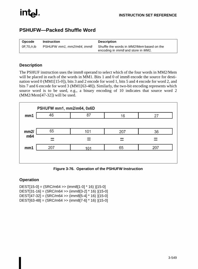
INSTRUCTION SET REFERENCE
PSHUFW—Packed Shuffle Word
Description
The PSHUF instruction uses the imm8 operand to select which of the four words in MM2/Memwill be placed in each of the words in MM1. Bits 1 and 0 of imm8 encode the source for desti-nation word 0 (MM1[15-0]), bits 3 and 2 encode for word 1, bits 5 and 4 encode for word 2, andbits 7 and 6 encode for word 3 (MM1[63-48]). Similarly, the two-bit encoding represents whichsource word is to be used, e.g., a binary encoding of 10 indicates that source word 2(MM2/Mem[47-32]) will be used.
Figure 3-76. Operation of the PSHUFW Instruction
Operation
DEST[15-0] = (SRC/m64 >> (imm8[1-0] * 16) )[15-0]DEST[31-16] = (SRC/m64 >> (imm8[3-2] * 16) )[15-0]DEST[47-32] = (SRC/m64 >> (imm8[5-4] * 16) )[15-0]DEST[63-48] = (SRC/m64 >> (imm8[7-6] * 16) )[15-0]
Opcode Instruction Description
0F,70,/r,ib PSHUFW mm1, mm2/m64, imm8 Shuffle the words in MM2/Mem based on the encoding in imm8 and store in MM1.
mm1
mm2/m64
mm1
= = = =
3-549

INSTRUCTION SET REFERENCE
PSHUFW—Packed Shuffle Word (Continued)
Intel C/C++ Compiler Intrinsic Equivalent
Pre-4.0 Intel C/C++ Compiler intrinsic:
__m64 _m_pshufw(__m64 a, int n)
Version 4.0 and later Intel C/C++ Compiler intrinsic:
__m64 _mm_shuffle_pi16(__m64 a, int n)
Returns a combination of the four words of a. The selector n must be an immediate.
Numeric Exceptions
None.
Protected Mode Exceptions
#GP(0) For an illegal memory operand effective address in the CS, DS, ES, FS, orGS segments.
#SS(0) For an illegal address in the SS segment.
#PF (fault-code) For a page fault.
#UD If CR0.EM = 1.
#NM If TS bit in CR0 is set.
#MF If there is a pending FPU exception.
#AC For unaligned memory reference. To enable #AC exceptions, three condi-tions must be true(CR0.AM is set; EFLAGS.AC is set; current CPL is 3).
Real Address Mode Exceptions
Interrupt 13 If any part of the operand would lie outside of the effective address spacefrom 0 to 0FFFFH.
#UD If CR0.EM = 1.
#NM If TS bit in CR0 is set.
#MF If there is a pending FPU exception.
Virtual 8086 Mode Exceptions
Same exceptions as in Real Address Mode.
#PF(fault-code) For a page fault.
#AC For unaligned memory reference if the current privilege level is 3.
3-550
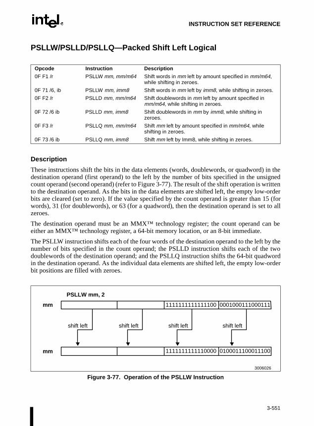
INSTRUCTION SET REFERENCE
an be
y the twoword
-order
PSLLW/PSLLD/PSLLQ—Packed Shift Left Logical
Description
These instructions shift the bits in the data elements (words, doublewords, or quadword) in thedestination operand (first operand) to the left by the number of bits specified in the unsignedcount operand (second operand) (refer to Figure 3-77). The result of the shift operation is writtento the destination operand. As the bits in the data elements are shifted left, the empty low-orderbits are cleared (set to zero). If the value specified by the count operand is greater than 15 (forwords), 31 (for doublewords), or 63 (for a quadword), then the destination operand is set to allzeroes.
The destination operand must be an MMX™ technology register; the count operand ceither an MMX™ technology register, a 64-bit memory location, or an 8-bit immediate.
The PSLLW instruction shifts each of the four words of the destination operand to the left bnumber of bits specified in the count operand; the PSLLD instruction shifts each of thedoublewords of the destination operand; and the PSLLQ instruction shifts the 64-bit quadin the destination operand. As the individual data elements are shifted left, the empty lowbit positions are filled with zeroes.
Opcode Instruction Description
0F F1 /r PSLLW mm, mm/m64 Shift words in mm left by amount specified in mm/m64, while shifting in zeroes.
0F 71 /6, ib PSLLW mm, imm8 Shift words in mm left by imm8, while shifting in zeroes.
0F F2 /r PSLLD mm, mm/m64 Shift doublewords in mm left by amount specified in mm/m64, while shifting in zeroes.
0F 72 /6 ib PSLLD mm, imm8 Shift doublewords in mm by imm8, while shifting in zeroes.
0F F3 /r PSLLQ mm, mm/m64 Shift mm left by amount specified in mm/m64, while shifting in zeroes.
0F 73 /6 ib PSLLQ mm, imm8 Shift mm left by Imm8, while shifting in zeroes.
Figure 3-77. Operation of the PSLLW Instruction
PSLLW mm, 2
mm
mm
1111111111111100
1111111111110000
0001000111000111
0100011100011100
shift left
shift left shift left shift left
3006026
3-551

INSTRUCTION SET REFERENCE
PSLLW/PSLLD/PSLLQ—Packed Shift Left Logical (Continued)
Operation
IF instruction is PSLLWTHEN
DEST(15..0) ← DEST(15..0) << COUNT;DEST(31..16) ← DEST(31..16) << COUNT;DEST(47..32) ← DEST(47..32) << COUNT;DEST(63..48) ← DEST(63..48) << COUNT;
ELSE IF instruction is PSLLDTHEN {
DEST(31..0) ← DEST(31..0) << COUNT;DEST(63..32) ← DEST(63..32) << COUNT;
ELSE (* instruction is PSLLQ *)DEST ← DEST << COUNT;
FI;
3-552

INSTRUCTION SET REFERENCE
PSLLW/PSLLD/PSLLQ—Packed Shift Left Logical (Continued)
Intel C/C++ Compiler Intrinsic Equivalents
Pre-4.0 Intel C/C++ Compiler intrinsic:
__m64 _m_psllw (__m64 m, __m64 count)
Version 4.0 and later Intel C/C++ Compiler intrinsic:
__m64 _mm_sll_pi16 (__m64 m, __m64 count)
Shifts four 16-bit values in m left the amount specified by count while shifting in zeroes.
Pre-4.0 Intel C/C++ Compiler intrinsic:
__m64 _m_psllwi (__m64 m, int count)
Version 4.0 and later Intel C/C++ Compiler intrinsic:
__m64 _mm_slli_pi16 (__m64 m, int count)
Shifts four 16-bit values in m left the amount specified by count while shifting in zeroes. For thebest performance, count should be a constant.
Pre-4.0 Intel C/C++ Compiler intrinsic:
__m64 _m_pslld (__m64 m, __m64 count)
Version 4.0 and later Intel C/C++ Compiler intrinsic:
__m64 _mm_sll_pi32 (__m64 m, __m64 count)
Shifts two 32-bit values in m left the amount specified by count while shifting in zeroes.
Pre-4.0 Intel C/C++ Compiler intrinsic:
__m64 _m_pslldi (__m64 m, int count)
Shifts two 32-bit values in m left the amount specified by count while shifting in zeroes. For thebest performance, count should be a constant.
Pre-4.0 Intel C/C++ Compiler intrinsic:
__m64 _m_psllq (__m64 m, __m64 count)
Version 4.0 and later Intel C/C++ Compiler intrinsic:
__m64 _mm_sll_si64 (__m64 m, __m64 count)
Shifts the 64-bit value in m left the amount specified by count while shifting in zeroes.
3-553

INSTRUCTION SET REFERENCE
PSLLW/PSLLD/PSLLQ—Packed Shift Left Logical (Continued)
Pre-4.0 Intel C/C++ Compiler intrinsic:
__m64 _m_psllqi (__m64 m, int count)
Version 4.0 and later Intel C/C++ Compiler intrinsic:
__m64 _mm_slli_si64 (__m64 m, int count)
Shifts the 64-bit value in m left the amount specified by count while shifting in zeroes. For thebest performance, count should be a constant.
Flags Affected
None.
Protected Mode Exceptions
#GP(0) If a memory operand effective address is outside the CS, DS, ES, FS, orGS segment limit.
#SS(0) If a memory operand effective address is outside the SS segment limit.
#UD If EM in CR0 is set.
#NM If TS in CR0 is set.
#MF If there is a pending FPU exception.
#PF(fault-code) If a page fault occurs.
#AC(0) If alignment checking is enabled and an unaligned memory reference ismade while the current privilege level is 3.
Real-Address Mode Exceptions
#GP If any part of the operand lies outside of the effective address space from0 to FFFFH.
#UD If EM in CR0 is set.
#NM If TS in CR0 is set.
#MF If there is a pending FPU exception.
3-554

INSTRUCTION SET REFERENCE
PSLLW/PSLLD/PSLLQ—Packed Shift Left Logical (Continued)
Virtual-8086 Mode Exceptions
#GP If any part of the operand lies outside of the effective address space from0 to FFFFH.
#UD If EM in CR0 is set.
#NM If TS in CR0 is set.
#MF If there is a pending FPU exception.
#PF(fault-code) If a page fault occurs.
#AC(0) If alignment checking is enabled and an unaligned memory reference ismade.
3-555

INSTRUCTION SET REFERENCE
ource 8-bit
ht bye two
ht, the
PSRAW/PSRAD—Packed Shift Right Arithmetic
Description
These instructions shift the bits in the data elements (words or doublewords) in the destinationoperand (first operand) to the right by the amount of bits specified in the unsigned count operand(second operand) (refer to Figure 3-78). The result of the shift operation is written to the desti-nation operand. The empty high-order bits of each element are filled with the initial value of thesign bit of the data element. If the value specified by the count operand is greater than 15 (forwords) or 31 (for doublewords), each destination data element is filled with the initial value ofthe sign bit of the element.
The destination operand must be an MMX™ technology register; the count operand (soperand) can be either an MMX™ technology register, a 64-bit memory location, or animmediate.
The PSRAW instruction shifts each of the four words in the destination operand to the rigthe number of bits specified in the count operand; the PSRAD instruction shifts each of thdoublewords in the destination operand. As the individual data elements are shifted rigempty high-order bit positions are filled with the sign value.
Opcode Instruction Description
0F E1 /r PSRAW mm, mm/m64
Shift words in mm right by amount specified in mm/m64 while shifting in sign bits.
0F 71 /4 ib PSRAW mm, imm8 Shift words in mm right by imm8 while shifting in sign bits
0F E2 /r PSRAD mm, mm/m64
Shift doublewords in mm right by amount specified in mm/m64 while shifting in sign bits.
0F 72 /4 ib PSRAD mm, imm8 Shift doublewords in mm right by imm8 while shifting in sign bits.
Figure 3-78. Operation of the PSRAW Instruction
PSRAW mm, 2
mm
mm
1111111111111100
1111111111111111
1101000111000111
1111010001110001
shift right shift rightshift right shift right
3006048
3-556

INSTRUCTION SET REFERENCE
PSRAW/PSRAD—Packed Shift Right Arithmetic (Continued)
OperationIF instruction is PSRAW
THENDEST(15..0) ← SignExtend (DEST(15..0) >> COUNT);DEST(31..16) ← SignExtend (DEST(31..16) >> COUNT);DEST(47..32) ← SignExtend (DEST(47..32) >> COUNT);DEST(63..48) ← SignExtend (DEST(63..48) >> COUNT);
ELSE { (*instruction is PSRAD *)DEST(31..0) ← SignExtend (DEST(31..0) >> COUNT);DEST(63..32) ← SignExtend (DEST(63..32) >> COUNT);
FI;
Intel C/C++ Compiler Intrinsic Equivalents
Pre-4.0 Intel C/C++ Compiler intrinsic:
__m64 _m_psraw (__m64 m, __m64 count)
Version 4.0 and later Intel C/C++ Compiler intrinsic:
__m64 _mm_sraw_pi16 (__m64 m, __m64 count)
Shifts four 16-bit values in m right the amount specified by count while shifting in the sign bit.
Pre-4.0 Intel C/C++ Compiler intrinsic:
__m64 _m_psrawi (__m64 m, int count)
Version 4.0 and later Intel C/C++ Compiler intrinsic:
__m64 _mm_srai_pi16 (__m64 m, int count)
Shifts four 16-bit values in m right the amount specified by count while shifting in the sign bit.For the best performance, count should be a constant.
Pre-4.0 Intel C/C++ Compiler intrinsic:
__m64 _m_psrad (__m64 m, __m64 count)
Version 4.0 and later Intel C/C++ Compiler intrinsic:
__m64 _mm_sra_pi32 (__m64 m, __m64 count)
Shifts two 32-bit values in m right the amount specified by count while shifting in the sign bit.
Pre-4.0 Intel C/C++ Compiler intrinsic:
__m64 _m_psradi (__m64 m, int count)
Version 4.0 and later Intel C/C++ Compiler intrinsic:
__m64 _mm_srai_pi32 (__m64 m, int count)
Shifts two 32-bit values in m right the amount specified by count while shifting in the sign bit.For the best performance, count should be a constant.
3-557

INSTRUCTION SET REFERENCE
PSRAW/PSRAD—Packed Shift Right Arithmetic (Continued)
Flags Affected
None.
Protected Mode Exceptions
#GP(0) If a memory operand effective address is outside the CS, DS, ES, FS, orGS segment limit.
#SS(0) If a memory operand effective address is outside the SS segment limit.
#UD If EM in CR0 is set.
#NM If TS in CR0 is set.
#MF If there is a pending FPU exception.
#PF(fault-code) If a page fault occurs.
#AC(0) If alignment checking is enabled and an unaligned memory reference ismade while the current privilege level is 3.
Real-Address Mode Exceptions
#GP If any part of the operand lies outside of the effective address space from0 to FFFFH.
#UD If EM in CR0 is set.
#NM If TS in CR0 is set.
#MF If there is a pending FPU exception.
Virtual-8086 Mode Exceptions
#GP If any part of the operand lies outside of the effective address space from0 to FFFFH.
#UD If EM in CR0 is set.
#NM If TS in CR0 is set.
#MF If there is a pending FPU exception.
#PF(fault-code) If a page fault occurs.
#AC(0) If alignment checking is enabled and an unaligned memory reference ismade.
3-558

INSTRUCTION SET REFERENCE
an be
ht bye twodword high-
PSRLW/PSRLD/PSRLQ—Packed Shift Right Logical
Description
These instructions shift the bits in the data elements (words, doublewords, or quadword) in thedestination operand (first operand) to the right by the number of bits specified in the unsignedcount operand (second operand) (refer to Figure 3-79). The result of the shift operation is writtento the destination operand. As the bits in the data elements are shifted right, the empty high-orderbits are cleared (set to zero). If the value specified by the count operand is greater than 15 (forwords), 31 (for doublewords), or 63 (for a quadword), then the destination operand is set to allzeroes.
The destination operand must be an MMX™ technology register; the count operand ceither an MMX™ technology register, a 64-bit memory location, or an 8-bit immediate.
The PSRLW instruction shifts each of the four words of the destination operand to the rigthe number of bits specified in the count operand; the PSRLD instruction shifts each of thdoublewords of the destination operand; and the PSRLQ instruction shifts the 64-bit quain the destination operand. As the individual data elements are shifted right, the emptyorder bit positions are filled with zeroes.
Opcode Instruction Description
0F D1 /r PSRLW mm, mm/m64 Shift words in mm right by amount specified in mm/m64 while shifting in zeroes.
0F 71 /2 ib PSRLW mm, imm8 Shift words in mm right by imm8.
0F D2 /r PSRLD mm, mm/m64 Shift doublewords in mm right by amount specified in mm/m64 while shifting in zeroes.
0F 72 /2 ib PSRLD mm, imm8 Shift doublewords in mm right by imm8.
0F D3 /r PSRLQ mm, mm/m64 Shift mm right by amount specified in mm/m64 while shifting in zeroes.
0F 73 /2 ib PSRLQ mm, imm8 Shift mm right by imm8 while shifting in zeroes.
Figure 3-79. Operation of the PSRLW Instruction
PSRLW mm, 2
mm
mm
1111111111111100
0011111111111111
0001000111000111
0000010001110001
shift right shift rightshift right shift right
3006027
3-559

INSTRUCTION SET REFERENCE
PSRLW/PSRLD/PSRLQ—Packed Shift Right Logical (Continued)
Operation
IF instruction is PSRLWTHEN {
DEST(15..0) ← DEST(15..0) >> COUNT;DEST(31..16) ← DEST(31..16) >> COUNT;DEST(47..32) ← DEST(47..32) >> COUNT;DEST(63..48) ← DEST(63..48) >> COUNT;
ELSE IF instruction is PSRLDTHEN {
DEST(31..0) ← DEST(31..0) >> COUNT;DEST(63..32) ← DEST(63..32) >> COUNT;
ELSE (* instruction is PSRLQ *)DEST ← DEST >> COUNT;
FI;
3-560

INSTRUCTION SET REFERENCE
PSRLW/PSRLD/PSRLQ—Packed Shift Right Logical (Continued)
Intel C/C++ Compiler Intrinsic Equivalents
Pre-4.0 Intel C/C++ Compiler intrinsic:
__m64 _m_psrlw (__m64 m, __m64 count)
Version 4.0 and later Intel C/C++ Compiler intrinsic:
__m64 _mm_srl_pi16 (__m64 m, __m64 count)
Shifts four 16-bit values in m right the amount specified by count while shifting in zeroes.
Pre-4.0 Intel C/C++ Compiler intrinsic:
__m64 _m_psrlwi (__m64 m, int count)
Version 4.0 and later Intel C/C++ Compiler intrinsic:
__m64 _mm_srli_pi16 (__m64 m, int count)
Shifts four 16-bit values in m right the amount specified by count while shifting in zeroes. Forthe best performance, count should be a constant.
Pre-4.0 Intel C/C++ Compiler intrinsic:
__m64 _m_psrld (__m64 m, __m64 count)
Version 4.0 and later Intel C/C++ Compiler intrinsic:
__m64 _mm_sri_pi32 (__m64 m, __m64 count)
Shifts two 32-bit values in m right the amount specified by count while shifting in zeroes.
Pre-4.0 Intel C/C++ Compiler intrinsic:
__m64 _m_psrldi (__m64 m, int count)
Version 4.0 and later Intel C/C++ Compiler intrinsic:
__m64 _mm_srli_pi32 (__m64 m, int count)
Shifts two 32-bit values in m right the amount specified by count while shifting in zeroes. Forthe best performance, count should be a constant.
Pre-4.0 Intel C/C++ Compiler intrinsic:
__m64 _m_psrlq (__m64 m, __m64 count)
Version 4.0 and later Intel C/C++ Compiler intrinsic:
__m64 _mm_srl_si64 (__m64 m, __m64 count)
Shifts the 64-bit value in m right the amount specified by count while shifting in zeroes.
3-561

INSTRUCTION SET REFERENCE
PSRLW/PSRLD/PSRLQ—Packed Shift Right Logical (Continued)
Pre-4.0 Intel C/C++ Compiler intrinsic:
__m64 _m_psrlqi (__m64 m, int count)
Version 4.0 and later Intel C/C++ Compiler intrinsic:
__m64 _mm_srli_si64 (__m64 m, int count)
Shifts the 64-bit value in m right the amount specified by count while shifting in zeroes. For thebest performance, count should be a constant.
Flags Affected
None.
Protected Mode Exceptions
#GP(0) If a memory operand effective address is outside the CS, DS, ES, FS, orGS segment limit.
#SS(0) If a memory operand effective address is outside the SS segment limit.
#UD If EM in CR0 is set.
#NM If TS in CR0 is set.
#MF If there is a pending FPU exception.
#PF(fault-code) If a page fault occurs.
#AC(0) If alignment checking is enabled and an unaligned memory reference ismade while the current privilege level is 3.
Real-Address Mode Exceptions
#GP If any part of the operand lies outside of the effective address space from0 to FFFFH.
#UD If EM in CR0 is set.
#NM If TS in CR0 is set.
#MF If there is a pending FPU exception.
3-562

INSTRUCTION SET REFERENCE
PSRLW/PSRLD/PSRLQ—Packed Shift Right Logical (Continued)
Virtual-8086 Mode Exceptions
#GP If any part of the operand lies outside of the effective address space from0 to FFFFH.
#UD If EM in CR0 is set.
#NM If TS in CR0 is set.
#MF If there is a pending FPU exception.
#PF(fault-code) If a page fault occurs.
#AC(0) If alignment checking is enabled and an unaligned memory reference ismade.
3-563
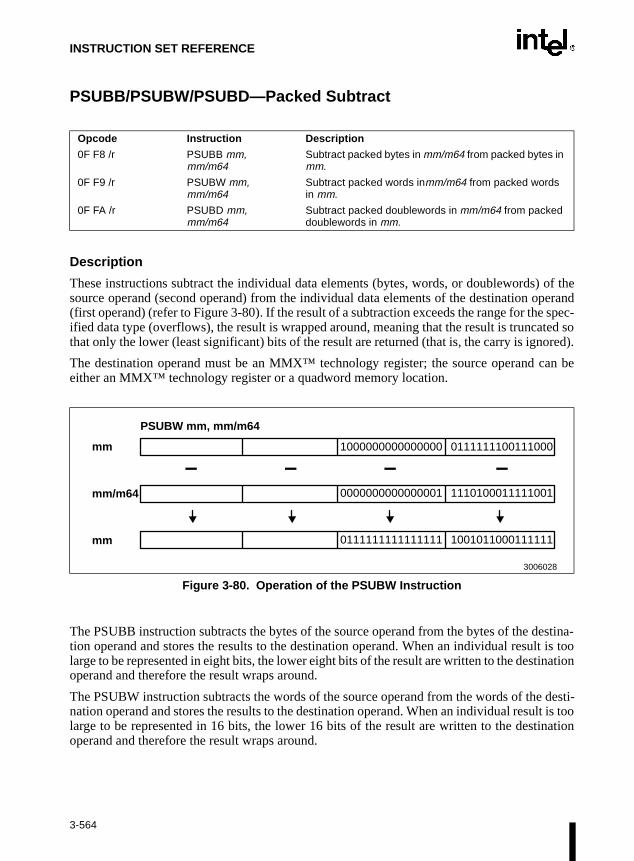
INSTRUCTION SET REFERENCE
an be
estina-t is tooination
desti-lt is toonation
PSUBB/PSUBW/PSUBD—Packed Subtract
Description
These instructions subtract the individual data elements (bytes, words, or doublewords) of thesource operand (second operand) from the individual data elements of the destination operand(first operand) (refer to Figure 3-80). If the result of a subtraction exceeds the range for the spec-ified data type (overflows), the result is wrapped around, meaning that the result is truncated sothat only the lower (least significant) bits of the result are returned (that is, the carry is ignored).
The destination operand must be an MMX™ technology register; the source operand ceither an MMX™ technology register or a quadword memory location.
The PSUBB instruction subtracts the bytes of the source operand from the bytes of the dtion operand and stores the results to the destination operand. When an individual resullarge to be represented in eight bits, the lower eight bits of the result are written to the destoperand and therefore the result wraps around.
The PSUBW instruction subtracts the words of the source operand from the words of thenation operand and stores the results to the destination operand. When an individual resularge to be represented in 16 bits, the lower 16 bits of the result are written to the destioperand and therefore the result wraps around.
Opcode Instruction Description
0F F8 /r PSUBB mm, mm/m64
Subtract packed bytes in mm/m64 from packed bytes in mm.
0F F9 /r PSUBW mm, mm/m64
Subtract packed words inmm/m64 from packed words in mm.
0F FA /r PSUBD mm, mm/m64
Subtract packed doublewords in mm/m64 from packed doublewords in mm.
Figure 3-80. Operation of the PSUBW Instruction
PSUBW mm, mm/m64
mm
mm/m64
mm
1000000000000000
0000000000000001
0111111111111111
0111111100111000
1110100011111001
1001011000111111
3006028
– –– –
3-564

INSTRUCTION SET REFERENCE
ration”
PSUBB/PSUBW/PSUBD—Packed Subtract (Continued)The PSUBD instruction subtracts the doublewords of the source operand from the doublewordsof the destination operand and stores the results to the destination operand. When an individualresult is too large to be represented in 32 bits, the lower 32 bits of the result are written to thedestination operand and therefore the result wraps around.
Note that like the integer SUB instruction, the PSUBB, PSUBW, and PSUBD instructions canoperate on either unsigned or signed (two’s complement notation) packed integers. Unlike theinteger instructions, none of the MMX™ instructions affect the EFLAGS register. WithMMX™ instructions, there are no carry or overflow flags to indicate when overflow hasoccurred, so the software must control the range of values or else use the “with satuMMX™ instructions.
Operation
IF instruction is PSUBBTHEN
DEST(7..0) ← DEST(7..0) – SRC(7..0); DEST(15..8) ← DEST(15..8) – SRC(15..8);DEST(23..16) ← DEST(23..16) – SRC(23..16);DEST(31..24) ← DEST(31..24) – SRC(31..24);DEST(39..32) ← DEST(39..32) – SRC(39..32);DEST(47..40) ← DEST(47..40) – SRC(47..40);DEST(55..48) ← DEST(55..48) – SRC(55..48);DEST(63..56) ← DEST(63..56) – SRC(63..56);
ELSEIF instruction is PSUBWTHEN
DEST(15..0) ← DEST(15..0) – SRC(15..0);DEST(31..16) ← DEST(31..16) – SRC(31..16);DEST(47..32) ← DEST(47..32) – SRC(47..32);DEST(63..48) ← DEST(63..48) – SRC(63..48);
ELSE { (* instruction is PSUBD *)DEST(31..0) ← DEST(31..0) – SRC(31..0);DEST(63..32) ← DEST(63..32) – SRC(63..32);
FI;
3-565

INSTRUCTION SET REFERENCE
PSUBB/PSUBW/PSUBD—Packed Subtract (Continued)
Intel C/C++ Compiler Intrinsic Equivalents
Pre-4.0 Intel C/C++ Compiler intrinsic:
__m64 _m_psubb(__m64 m1, __m64 m2)
Version 4.0 and later Intel C/C++ Compiler intrinsic:
__m64 _mm_sub_pi8(__m64 m1, __m64 m2)
Subtract the eight 8-bit values in m2 from the eight 8-bit values in m1.
Pre-4.0 Intel C/C++ Compiler intrinsic:
__m64 _m_psubw(__m64 m1, __m64 m2)
Version 4.0 and later Intel C/C++ Compiler intrinsic:
__m64 _mm_sub_pi16(__m64 m1, __m64 m2)
Subtract the four 16-bit values in m2 from the four 16-bit values in m1.
Pre-4.0 Intel C/C++ Compiler intrinsic:
__m64 _m_psubd(__m64 m1, __m64 m2)
Version 4.0 and later Intel C/C++ Compiler intrinsic:
__m64 _mm_sub_pi32(__m64 m1, __m64 m2)
Subtract the two 32-bit values in m2 from the two 32-bit values in m1.
Flags Affected
None.
Protected Mode Exceptions
#GP(0) If a memory operand effective address is outside the CS, DS, ES, FS, orGS segment limit.
#SS(0) If a memory operand effective address is outside the SS segment limit.
#UD If EM in CR0 is set.
#NM If TS in CR0 is set.
#MF If there is a pending FPU exception.
#PF(fault-code) If a page fault occurs.
#AC(0) If alignment checking is enabled and an unaligned memory reference ismade while the current privilege level is 3.
3-566

INSTRUCTION SET REFERENCE
PSUBB/PSUBW/PSUBD—Packed Subtract (Continued)
Real-Address Mode Exceptions
#GP If any part of the operand lies outside of the effective address space from0 to FFFFH.
#UD If EM in CR0 is set.
#NM If TS in CR0 is set.
#MF If there is a pending FPU exception.
Virtual-8086 Mode Exceptions
#GP If any part of the operand lies outside of the effective address space from0 to FFFFH.
#UD If EM in CR0 is set.
#NM If TS in CR0 is set.
#MF If there is a pending FPU exception.
#PF(fault-code) If a page fault occurs.
#AC(0) If alignment checking is enabled and an unaligned memory reference ismade.
3-567

INSTRUCTION SET REFERENCE
ologyword
d bytesividuale satu-
signedan indi-s thanation
PSUBSB/PSUBSW—Packed Subtract with Saturation
Description
These instructions subtract the individual signed data elements (bytes or words) of the sourceoperand (second operand) from the individual signed data elements of the destination operand(first operand) (refer to Figure 3-81). If the result of a subtraction exceeds the range for the spec-ified data type, the result is saturated. The destination operand must be an MMX™ technregister; the source operand can be either an MMX™ technology register or a quadmemory location.
The PSUBSB instruction subtracts the signed bytes of the source operand from the signeof the destination operand and stores the results to the destination operand. When an indresult is beyond the range of a signed byte (that is, greater than 7FH or less than 80H), thrated byte value of 7FH or 80H, respectively, is written to the destination operand.
The PSUBSW instruction subtracts the signed words of the source operand from the words of the destination operand and stores the results to the destination operand. When vidual result is beyond the range of a signed word (that is, greater than 7FFFH or les8000H), the saturated word value of 7FFFH or 8000H, respectively, is written to the destinoperand.
Opcode Instruction Description
0F E8 /r PSUBSB mm, mm/m64
Subtract signed packed bytes in mm/m64 from signed packed bytes in mm and saturate.
0F E9 /r PSUBSW mm, mm/m64
Subtract signed packed words in mm/m64 from signed packed words in mm and saturate.
Figure 3-81. Operation of the PSUBSW Instruction
PSUBSW mm, mm/m64
mm
mm/m64
mm
1000000000000000
0000000000000001
1000000000000000
0111111100111000
1110100011111001
0111111111111111
3006029
– –– –
3-568

INSTRUCTION SET REFERENCE
PSUBSB/PSUBSW—Packed Subtract with Saturation (Continued)
Operation
IF instruction is PSUBSBTHEN
DEST(7..0) ← SaturateToSignedByte(DEST(7..0) – SRC (7..0));DEST(15..8) ← SaturateToSignedByte(DEST(15..8) – SRC(15..8));DEST(23..16) ← SaturateToSignedByte(DEST(23..16) – SRC(23..16));DEST(31..24) ← SaturateToSignedByte(DEST(31..24) – SRC(31..24));DEST(39..32) ← SaturateToSignedByte(DEST(39..32) – SRC(39..32));DEST(47..40) ← SaturateToSignedByte(DEST(47..40) – SRC(47..40));DEST(55..48) ← SaturateToSignedByte(DEST(55..48) – SRC(55..48));DEST(63..56) ← SaturateToSignedByte(DEST(63..56) – SRC(63..56))
ELSE (* instruction is PSUBSW *)DEST(15..0) ← SaturateToSignedWord(DEST(15..0) – SRC(15..0));DEST(31..16) ← SaturateToSignedWord(DEST(31..16) – SRC(31..16));DEST(47..32) ← SaturateToSignedWord(DEST(47..32) – SRC(47..32));DEST(63..48) ← SaturateToSignedWord(DEST(63..48) – SRC(63..48));
FI;
Intel C/C++ Compiler Intrinsic Equivalents
Pre-4.0 Intel C/C++ Compiler intrinsic:
__m64 _m_psubsb(__m64 m1, __m64 m2)
Version 4.0 and later Intel C/C++ Compiler intrinsic:
__m64 _mm_subs_pi8(__m64 m1, __m64 m2)
Subtract the eight signed 8-bit values in m2 from the eight signed 8-bit values in m1 and saturate.
Pre-4.0 Intel C/C++ Compiler intrinsic:
__m64 _m_psubsw(__m64 m1, __m64 m2)
Version 4.0 and later Intel C/C++ Compiler intrinsic:
__m64 _mm_subs_pi16(__m64 m1, __m64 m2)
Subtract the four signed 16-bit values in m2 from the four signed 16-bit values in m1 and satu-rate.
Flags Affected
None.
3-569

INSTRUCTION SET REFERENCE
PSUBSB/PSUBSW—Packed Subtract with Saturation (Continued)
Protected Mode Exceptions
#GP(0) If a memory operand effective address is outside the CS, DS, ES, FS, orGS segment limit.
#SS(0) If a memory operand effective address is outside the SS segment limit.
#UD If EM in CR0 is set.
#NM If TS in CR0 is set.
#MF If there is a pending FPU exception.
#PF(fault-code) If a page fault occurs.
#AC(0) If alignment checking is enabled and an unaligned memory reference ismade while the current privilege level is 3.
Real-Address Mode Exceptions
#GP If any part of the operand lies outside of the effective address space from0 to FFFFH.
#UD If EM in CR0 is set.
#NM If TS in CR0 is set.
#MF If there is a pending FPU exception.
Virtual-8086 Mode Exceptions
#GP If any part of the operand lies outside of the effective address space from0 to FFFFH.
#UD If EM in CR0 is set.
#NM If TS in CR0 is set.
#MF If there is a pending FPU exception.
#PF(fault-code) If a page fault occurs.
#AC(0) If alignment checking is enabled and an unaligned memory reference ismade.
3-570

INSTRUCTION SET REFERENCE
ister
signedan indi-00H is
theperand.d value
PSUBUSB/PSUBUSW—Packed Subtract Unsigned with Saturation
Description
These instructions subtract the individual unsigned data elements (bytes or words) of the sourceoperand (second operand) from the individual unsigned data elements of the destination operand(first operand) (refer to Figure 3-82). If the result of an individual subtraction exceeds the rangefor the specified unsigned data type, the result is saturated. The destination operand musts be anMMX™ technology register; the source operand can be either an MMX™ technology regor a quadword memory location.
The PSUBUSB instruction subtracts the unsigned bytes of the source operand from the unbytes of the destination operand and stores the results to the destination operand. When vidual result is less than zero (a negative value), the saturated unsigned byte value of written to the destination operand.
The PSUBUSW instruction subtracts the unsigned words of the source operand fromunsigned words of the destination operand and stores the results to the destination oWhen an individual result is less than zero (a negative value), the saturated unsigned worof 0000H is written to the destination operand.
Opcode Instruction Description
0F D8 /r PSUBUSB mm, mm/m64
Subtract unsigned packed bytes in mm/m64 from unsigned packed bytes in mm and saturate.
0F D9 /r PSUBUSW mm, mm/m64
Subtract unsigned packed words in mm/m64 from unsigned packed words in mm and saturate.
Figure 3-82. Operation of the PSUBUSB Instruction
PSUBUSB mm, mm/m64
mm
mm/m64
mm
10000000
11111111
00000000
01111111
00010111
01101000
11111000
00000111
11110001
3006030
– –––––– –
3-571

INSTRUCTION SET REFERENCE
PSUBUSB/PSUBUSW—Packed Subtract Unsigned with Saturation (Continued)
Operation
IF instruction is PSUBUSBTHEN
DEST(7..0) ← SaturateToUnsignedByte (DEST(7..0 – SRC (7..0) );DEST(15..8) ← SaturateToUnsignedByte ( DEST(15..8) – SRC(15..8) );DEST(23..16) ← SaturateToUnsignedByte (DEST(23..16) – SRC(23..16) );DEST(31..24) ← SaturateToUnsignedByte (DEST(31..24) – SRC(31..24) );DEST(39..32) ← SaturateToUnsignedByte (DEST(39..32) – SRC(39..32) );DEST(47..40) ← SaturateToUnsignedByte (DEST(47..40) – SRC(47..40) );DEST(55..48) ← SaturateToUnsignedByte (DEST(55..48) – SRC(55..48) );DEST(63..56) ← SaturateToUnsignedByte (DEST(63..56) – SRC(63..56) );
ELSE { (* instruction is PSUBUSW *)DEST(15..0) ← SaturateToUnsignedWord (DEST(15..0) – SRC(15..0) );DEST(31..16) ← SaturateToUnsignedWord (DEST(31..16) – SRC(31..16) );DEST(47..32) ← SaturateToUnsignedWord (DEST(47..32) – SRC(47..32) );DEST(63..48) ← SaturateToUnsignedWord (DEST(63..48) – SRC(63..48) );
FI;
Intel C/C++ Compiler Intrinsic Equivalents
Pre-4.0 Intel C/C++ Compiler intrinsic:
__m64 _m_psubusb(__m64 m1, __m64 m2)
Version 4.0 and later Intel C/C++ Compiler intrinsic:
__m64 _mm_sub_pu8(__m64 m1, __m64 m2)
Subtract the eight unsigned 8-bit values in m2 from the eight unsigned 8-bit values in m1 andsaturate.
Pre-4.0 Intel C/C++ Compiler intrinsic:
__m64 _m_psubusw(__m64 m1, __m64 m2)
Version 4.0 and later Intel C/C++ Compiler intrinsic:
__m64 _mm_sub_pu16(__m64 m1, __m64 m2)
Subtract the four unsigned 16-bit values in m2 from the four unsigned 16-bit values in m1 andsaturate.
Flags Affected
None.
3-572

INSTRUCTION SET REFERENCE
PSUBUSB/PSUBUSW—Packed Subtract Unsigned with Saturation (Continued)
Protected Mode Exceptions
#GP(0) If a memory operand effective address is outside the CS, DS, ES, FS, orGS segment limit.
#SS(0) If a memory operand effective address is outside the SS segment limit.
#UD If EM in CR0 is set.
#NM If TS in CR0 is set.
#MF If there is a pending FPU exception.
#PF(fault-code) If a page fault occurs.
#AC(0) If alignment checking is enabled and an unaligned memory reference ismade while the current privilege level is 3.
Real-Address Mode Exceptions
#GP If any part of the operand lies outside of the effective address space from0 to FFFFH.
#UD If EM in CR0 is set.
#NM If TS in CR0 is set.
#MF If there is a pending FPU exception.
Virtual-8086 Mode Exceptions
#GP If any part of the operand lies outside of the effective address space from0 to FFFFH.
#UD If EM in CR0 is set.
#NM If TS in CR0 is set.
#MF If there is a pending FPU exception.
#PF(fault-code) If a page fault occurs.
#AC(0) If alignment checking is enabled and an unaligned memory reference ismade.
3-573

INSTRUCTION SET REFERENCE
her anom as only
d anderand.
d anderand.
d andation
PUNPCKHBW/PUNPCKHWD/PUNPCKHDQ—Unpack High Packed Data
Description
These instructions unpack and interleave the high-order data elements (bytes, words, or double-words) of the destination operand (first operand) and source operand (second operand) into thedestination operand (refer to Figure 3-83). The low-order data elements are ignored. The desti-nation operand must be an MMX™ technology register; the source operand may be eitMMX™ technology register or a 64-bit memory location. When the source data comes frmemory operand, the full 64-bit operand is accessed from memory, but the instruction usethe high-order 32 bits.
The PUNPCKHBW instruction interleaves the four high-order bytes of the source operanthe four high-order bytes of the destination operand and writes them to the destination op
The PUNPCKHWD instruction interleaves the two high-order words of the source operanthe two high-order words of the destination operand and writes them to the destination op
The PUNPCKHDQ instruction interleaves the high-order doubleword of the source operanthe high-order doubleword of the destination operand and writes them to the destinoperand.
Opcode Instruction Description
0F 68 /r PUNPCKHBW mm, mm/m64
Interleave high-order bytes from mm and mm/m64 into mm.
0F 69 /r PUNPCKHWD mm, mm/m64
Interleave high-order words from mm and mm/m64 into mm.
0F 6A /r PUNPCKHDQ mm, mm/m64
Interleave high-order doublewords from mm and mm/m64 into mm.
Figure 3-83. High-Order Unpacking and Interleaving of BytesWith the PUNPCKHBW Instruction
PUNPCKHBW mm, mm/m64mm/m64 mm
1 1 1 1 1 1 1 12 2 2 2 2 2 2 2
mm2 1 2 1 2 1 2 1
3006031
7 6 5 4 3 2 1 0 7 6 5 4 3 2 1 0
7 7 6 6 5 5 4 4
3-574

INSTRUCTION SET REFERENCE
PUNPCKHBW/PUNPCKHWD/PUNPCKHDQ—Unpack High Packed Data (Continued)If the source operand is all zeroes, the result (stored in the destination operand) contains zeroextensions of the high-order data elements from the original value in the destination operand.With the PUNPCKHBW instruction the high-order bytes are zero extended (that is, unpackedinto unsigned words), and with the PUNPCKHWD instruction, the high-order words are zeroextended (unpacked into unsigned doublewords).
Operation
IF instruction is PUNPCKHBWTHEN
DEST(7..0) ← DEST(39..32);DEST(15..8) ← SRC(39..32);DEST(23..16) ← DEST(47..40);DEST(31..24) ← SRC(47..40);DEST(39..32) ← DEST(55..48);DEST(47..40) ← SRC(55..48);DEST(55..48) ← DEST(63..56);DEST(63..56) ← SRC(63..56);
ELSE IF instruction is PUNPCKHWTHEN
DEST(15..0) ← DEST(47..32); DEST(31..16) ← SRC(47..32);DEST(47..32) ← DEST(63..48);DEST(63..48) ← SRC(63..48);
ELSE (* instruction is PUNPCKHDQ *)DEST(31..0) ← DEST(63..32)DEST(63..32) ← SRC(63..32);
FI;
3-575

INSTRUCTION SET REFERENCE
PUNPCKHBW/PUNPCKHWD/PUNPCKHDQ—Unpack High Packed Data (Continued)
Intel C/C++ Compiler Intrinsic Equivalents
Pre-4.0 Intel C/C++ Compiler intrinsic:
__m64 _m_punpckhbw (__m64 m1, __m64 m2)
Version 4.0 and later Intel C/C++ Compiler intrinsic:
__m64 _mm_unpckhi_pi8 (__m64 m1, __m64 m2)
Interleave the four 8-bit values from the high half of m1 with the four values from the high halfof m2 and take the least significant element from m1.
Pre-4.0 Intel C/C++ Compiler intrinsic:
__m64 _m_punpckhwd (__m64 m1, __m64 m2)
Version 4.0 and later Intel C/C++ Compiler intrinsic:
__m64 _mm_unpckhi_pi16 (__m64 m1, __m64 m2)
Interleave the two 16-bit values from the high half of m1 with the two values from the high halfof m2 and take the least significant element from m1.
Pre-4.0 Intel C/C++ Compiler intrinsic:
__m64 _m_punpckhdq (__m64 m1, __m64 m2)
Version 4.0 and later Intel C/C++ Compiler intrinsic:
__m64 _mm_unpckhi_pi32 (__m64 m1, __m64 m2)
Interleave the 32-bit value from the high half of m1 with the 32-bit value from the high half ofm2 and take the least significant element from m1.
Flags Affected
None.
3-576

INSTRUCTION SET REFERENCE
PUNPCKHBW/PUNPCKHWD/PUNPCKHDQ—Unpack High Packed Data (Continued)
Protected Mode Exceptions
#GP(0) If a memory operand effective address is outside the CS, DS, ES, FS, orGS segment limit.
#SS(0) If a memory operand effective address is outside the SS segment limit.
#UD If EM in CR0 is set.
#NM If TS in CR0 is set.
#MF If there is a pending FPU exception.
#PF(fault-code) If a page fault occurs.
#AC(0) If alignment checking is enabled and an unaligned memory reference ismade while the current privilege level is 3.
Real-Address Mode Exceptions
#GP If any part of the operand lies outside of the effective address space from0 to FFFFH.
#UD If EM in CR0 is set.
#NM If TS in CR0 is set.
#MF If there is a pending FPU exception.
Virtual-8086 Mode Exceptions
#GP If any part of the operand lies outside of the effective address space from0 to FFFFH.
#UD If EM in CR0 is set.
#NM If TS in CR0 is set.
#MF If there is a pending FPU exception.
#PF(fault-code) If a page fault occurs.
#AC(0) If alignment checking is enabled and an unaligned memory reference ismade.
3-577
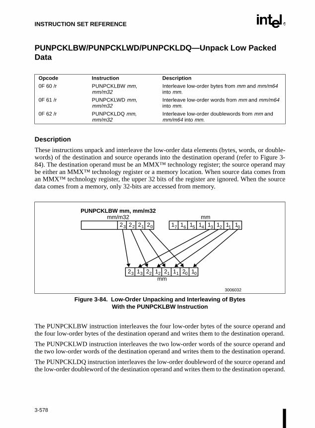
INSTRUCTION SET REFERENCE
d may fromource
anderand.
anderand.
d anderand.
PUNPCKLBW/PUNPCKLWD/PUNPCKLDQ—Unpack Low Packed Data
Description
These instructions unpack and interleave the low-order data elements (bytes, words, or double-words) of the destination and source operands into the destination operand (refer to Figure 3-84). The destination operand must be an MMX™ technology register; the source operanbe either an MMX™ technology register or a memory location. When source data comesan MMX™ technology register, the upper 32 bits of the register are ignored. When the sdata comes from a memory, only 32-bits are accessed from memory.
The PUNPCKLBW instruction interleaves the four low-order bytes of the source operandthe four low-order bytes of the destination operand and writes them to the destination op
The PUNPCKLWD instruction interleaves the two low-order words of the source operandthe two low-order words of the destination operand and writes them to the destination op
The PUNPCKLDQ instruction interleaves the low-order doubleword of the source operanthe low-order doubleword of the destination operand and writes them to the destination op
Opcode Instruction Description
0F 60 /r PUNPCKLBW mm, mm/m32
Interleave low-order bytes from mm and mm/m64 into mm.
0F 61 /r PUNPCKLWD mm, mm/m32
Interleave low-order words from mm and mm/m64 into mm.
0F 62 /r PUNPCKLDQ mm, mm/m32
Interleave low-order doublewords from mm and mm/m64 into mm.
Figure 3-84. Low-Order Unpacking and Interleaving of BytesWith the PUNPCKLBW Instruction
PUNPCKLBW mm, mm/m32mm/m32 mm
1 1 1 1 1 1 1 12 2 2 2
mm2 1 2 1 2 1 2 1
3006032
3 3 2 2 1 1 0 0
3 2 1 0 7 6 5 4 3 2 1 0
3-578

INSTRUCTION SET REFERENCE
PUNPCKLBW/PUNPCKLWD/PUNPCKLDQ—Unpack Low Packed Data (Continued)
If the source operand is all zeroes, the result (stored in the destination operand) contains zeroextensions of the high-order data elements from the original value in the destination operand.With the PUNPCKLBW instruction the low-order bytes are zero extended (that is, unpackedinto unsigned words), and with the PUNPCKLWD instruction, the low-order words are zeroextended (unpacked into unsigned doublewords).
Operation
IF instruction is PUNPCKLBWTHEN
DEST(63..56) ← SRC(31..24);DEST(55..48) ← DEST(31..24);DEST(47..40) ← SRC(23..16);DEST(39..32) ← DEST(23..16);DEST(31..24) ← SRC(15..8);DEST(23..16) ← DEST(15..8);DEST(15..8) ← SRC(7..0);DEST(7..0) ← DEST(7..0);
ELSE IF instruction is PUNPCKLWDTHEN
DEST(63..48) ← SRC(31..16);DEST(47..32) ← DEST(31..16);DEST(31..16) ← SRC(15..0);DEST(15..0) ← DEST(15..0);
ELSE (* instruction is PUNPCKLDQ *)DEST(63..32) ← SRC(31..0);DEST(31..0) ← DEST(31..0);
FI;
3-579

INSTRUCTION SET REFERENCE
PUNPCKLBW/PUNPCKLWD/PUNPCKLDQ—Unpack Low Packed Data (Continued)
Intel C/C++ Compiler Intrinsic Equivalents
Pre-4.0 Intel C/C++ Compiler intrinsic:
__m64 _m_punpcklbw (__m64 m1, __m64 m2)
Version 4.0 and later Intel C/C++ Compiler intrinsic:
__m64 _mm_unpcklo_pi8 (__m64 m1, __m64 m2)
Interleave the four 8-bit values from the low half of m1 with the four values from the low halfof m2 and take the least significant element from m1.
Pre-4.0 Intel C/C++ Compiler intrinsic:
__m64 _m_punpcklwd (__m64 m1, __m64 m2)
Version 4.0 and later Intel C/C++ Compiler intrinsic:
__m64 _mm_unpcklo_pi16 (__m64 m1, __m64 m2)
Interleave the two 16-bit values from the low half of m1 with the two values from the low halfof m2 and take the least significant element from m1.
Pre-4.0 Intel C/C++ Compiler intrinsic:
__m64 _m_punpckldq (__m64 m1, __m64 m2)
Version 4.0 and later Intel C/C++ Compiler intrinsic:
__m64 _mm_unpcklo_pi32 (__m64 m1, __m64 m2)
Interleave the 32-bit value from the low half of m1 with the 32-bit value from the low half ofm2 and take the least significant element from m1.
Protected Mode Exceptions
#GP(0) If a memory operand effective address is outside the CS, DS, ES, FS, orGS segment limit.
#SS(0) If a memory operand effective address is outside the SS segment limit.
#UD If EM in CR0 is set.
#NM If TS in CR0 is set.
#MF If there is a pending FPU exception.
#PF(fault-code) If a page fault occurs.
#AC(0) If alignment checking is enabled and an unaligned memory reference ismade while the current privilege level is 3.
3-580

INSTRUCTION SET REFERENCE
PUNPCKLBW/PUNPCKLWD/PUNPCKLDQ—Unpack Low Packed Data (Continued)
Real-Address Mode Exceptions
#GP If any part of the operand lies outside of the effective address space from0 to FFFFH.
#UD If EM in CR0 is set.
#NM If TS in CR0 is set.
#MF If there is a pending FPU exception.
Virtual-8086 Mode Exceptions
#GP If any part of the operand lies outside of the effective address space from0 to FFFFH.
#UD If EM in CR0 is set.
#NM If TS in CR0 is set.
#MF If there is a pending FPU exception.
#PF(fault-code) If a page fault occurs.
#AC(0) If alignment checking is enabled and an unaligned memory reference ismade.
3-581

INSTRUCTION SET REFERENCE
ment’scurrentttributehen thee stack
instruc- ESPss of the
cuted,ate this
es thetrue inructionby 2).
PUSH—Push Word or Doubleword Onto the Stack
Description
This instruction decrements the stack pointer and then stores the source operand on the top ofthe stack. The address-size attribute of the stack segment determines the stack pointer size (16bits or 32 bits), and the operand-size attribute of the current code segment determines theamount the stack pointer is decremented (two bytes or four bytes). For example, if these address-and operand-size attributes are 32, the 32-bit ESP register (stack pointer) is decremented by fourand, if they are 16, the 16-bit SP register is decremented by 2.(The B flag in the stack segsegment descriptor determines the stack’s address-size attribute, and the D flag in the code segment’s segment descriptor, along with prefixes, determines the operand-size aand also the address-size attribute of the source operand.) Pushing a 16-bit operand wstack address-size attribute is 32 can result in a misaligned the stack pointer (that is, thpointer is not aligned on a doubleword boundary).
The PUSH ESP instruction pushes the value of the ESP register as it existed before the tion was executed. Thus, if a PUSH instruction uses a memory operand in which theregister is used as a base register for computing the operand address, the effective addreoperand is computed before the ESP register is decremented.
In the real-address mode, if the ESP or SP register is 1 when the PUSH instruction is exethe processor shuts down due to a lack of stack space. No exception is generated to indiccondition.
Intel Architecture Compatibility
For Intel Architecture processors from the Intel 286 on, the PUSH ESP instruction pushvalue of the ESP register as it existed before the instruction was executed. (This is also the real-address and virtual-8086 modes.) For the Intel 8086 processor, the PUSH SP instpushes the new value of the SP register (that is the value after it has been decremented
Opcode Instruction Description
FF /6 PUSH r/m16 Push r/m16
FF /6 PUSH r/m32 Push r/m32
50+rw PUSH r16 Push r16
50+rd PUSH r32 Push r32
6A PUSH imm8 Push imm8
68 PUSH imm16 Push imm16
68 PUSH imm32 Push imm32
0E PUSH CS Push CS
16 PUSH SS Push SS
1E PUSH DS Push DS
06 PUSH ES Push ES
0F A0 PUSH FS Push FS
0F A8 PUSH GS Push GS
3-582

INSTRUCTION SET REFERENCE
PUSH—Push Word or Doubleword Onto the Stack (Continued)
Operation
IF StackAddrSize = 32THEN
IF OperandSize = 32THEN
ESP ← ESP − 4;SS:ESP ← SRC; (* push doubleword *)
ELSE (* OperandSize = 16*)ESP ← ESP − 2;SS:ESP ← SRC; (* push word *)
FI;ELSE (* StackAddrSize = 16*)
IF OperandSize = 16THEN
SP ← SP − 2; SS:SP ← SRC; (* push word *)
ELSE (* OperandSize = 32*)SP ← SP − 4;SS:SP ← SRC; (* push doubleword *)
FI;FI;
Flags Affected
None.
Protected Mode Exceptions
#GP(0) If a memory operand effective address is outside the CS, DS, ES, FS, orGS segment limit.
If the DS, ES, FS, or GS register is used to access memory and it containsa null segment selector.
#SS(0) If a memory operand effective address is outside the SS segment limit.
#PF(fault-code) If a page fault occurs.
#AC(0) If alignment checking is enabled and an unaligned memory reference ismade while the current privilege level is 3.
3-583
INSTRUCTION SET REFERENCE
PUSH—Push Word or Doubleword Onto the Stack (Continued)
Real-Address Mode Exceptions
#GP If a memory operand effective address is outside the CS, DS, ES, FS, orGS segment limit.
#SS If a memory operand effective address is outside the SS segment limit.
If the new value of the SP or ESP register is outside the stack segmentlimit.
Virtual-8086 Mode Exceptions
#GP(0) If a memory operand effective address is outside the CS, DS, ES, FS, orGS segment limit.
#SS(0) If a memory operand effective address is outside the SS segment limit.
#PF(fault-code) If a page fault occurs.
#AC(0) If alignment checking is enabled and an unaligned memory reference ismade.
3-584

INSTRUCTION SET REFERENCE
ction
pcode.d the
rce they treaterand- of the
HADption is
PUSHA/PUSHAD—Push All General-Purpose Registers
Description
These instructions push the contents of the general-purpose registers onto the stack. The regis-ters are stored on the stack in the following order: EAX, ECX, EDX, EBX, EBP, ESP (originalvalue), EBP, ESI, and EDI (if the current operand-size attribute is 32) and AX, CX, DX, BX, SP(original value), BP, SI, and DI (if the operand-size attribute is 16). These instructions performthe reverse operation of the POPA/POPAD instructions. The value pushed for the ESP or SPregister is its value before prior to pushing the first register (refer to the “Operation” sebelow).
The PUSHA (push all) and PUSHAD (push all double) mnemonics reference the same oThe PUSHA instruction is intended for use when the operand-size attribute is 16 anPUSHAD instruction for when the operand-size attribute is 32. Some assemblers may fooperand size to 16 when PUSHA is used and to 32 when PUSHAD is used. Others mathese mnemonics as synonyms (PUSHA/PUSHAD) and use the current setting of the opsize attribute to determine the size of values to be pushed from the stack, regardlessmnemonic used.
In the real-address mode, if the ESP or SP register is 1, 3, or 5 when the PUSHA/PUSinstruction is executed, the processor shuts down due to a lack of stack space. No excegenerated to indicate this condition.
Opcode Instruction Description
60 PUSHA Push AX, CX, DX, BX, original SP, BP, SI, and DI
60 PUSHAD Push EAX, ECX, EDX, EBX, original ESP, EBP, ESI, and EDI
3-585

INSTRUCTION SET REFERENCE
PUSHA/PUSHAD—Push All General-Purpose Register (Continued)
Operation
IF OperandSize = 32 (* PUSHAD instruction *)THEN
Temp ← (ESP);Push(EAX);Push(ECX);Push(EDX);Push(EBX);Push(Temp);Push(EBP);Push(ESI);Push(EDI);
ELSE (* OperandSize = 16, PUSHA instruction *)Temp ← (SP);Push(AX);Push(CX);Push(DX);Push(BX);Push(Temp);
Push(BP);Push(SI);Push(DI);
FI;
Flags Affected
None.
Protected Mode Exceptions
#SS(0) If the starting or ending stack address is outside the stack segment limit.
#PF(fault-code) If a page fault occurs.
#AC(0) If an unaligned memory reference is made while the current privilege levelis 3 and alignment checking is enabled.
3-586

INSTRUCTION SET REFERENCE
PUSHA/PUSHAD—Push All General-Purpose Register (Continued)
Real-Address Mode Exceptions
#GP If the ESP or SP register contains 7, 9, 11, 13, or 15.
Virtual-8086 Mode Exceptions
#GP(0) If the ESP or SP register contains 7, 9, 11, 13, or 15.
#PF(fault-code) If a page fault occurs.
#AC(0) If an unaligned memory reference is made while alignment checking isenabled.
3-587

INSTRUCTION SET REFERENCE
PUSHF/PUSHFD—Push EFLAGS Register onto the Stack
Description
These instructions decrement the stack pointer by four (if the current operand-size attribute is32) and pushes the entire contents of the EFLAGS register onto the stack, or decrements thestack pointer by two (if the operand-size attribute is 16) and pushes the lower 16 bits of theEFLAGS register (that is, the FLAGS register) onto the stack. (These instructions reverse theoperation of the POPF/POPFD instructions.) When copying the entire EFLAGS register to thestack, the VM and RF flags (bits 16 and 17) are not copied; instead, the values for these flagsare cleared in the EFLAGS image stored on the stack. Refer to Section 3.6.3. in Chapter 3, BasicExecution Environment of the Intel Architecture Software Developer’s Manual, Volume 1, forinformation about the EFLAGS registers.
The PUSHF (push flags) and PUSHFD (push flags double) mnemonics reference the sameopcode. The PUSHF instruction is intended for use when the operand-size attribute is 16 and thePUSHFD instruction for when the operand-size attribute is 32. Some assemblers may force theoperand size to 16 when PUSHF is used and to 32 when PUSHFD is used. Others may treat thesemnemonics as synonyms (PUSHF/PUSHFD) and use the current setting of the operand-sizeattribute to determine the size of values to be pushed from the stack, regardless of the mnemonicused.
When in virtual-8086 mode and the I/O privilege level (IOPL) is less than 3, thePUSHF/PUSHFD instruction causes a general protection exception (#GP).
In the real-address mode, if the ESP or SP register is 1, 3, or 5 when the PUSHA/PUSHADinstruction is executed, the processor shuts down due to a lack of stack space. No exception isgenerated to indicate this condition.
Opcode Instruction Description
9C PUSHF Push lower 16 bits of EFLAGS
9C PUSHFD Push EFLAGS
3-588

INSTRUCTION SET REFERENCE
PUSHF/PUSHFD—Push EFLAGS Register onto the Stack (Continued)
Operation
IF (PE=0) OR (PE=1 AND ((VM=0) OR (VM=1 AND IOPL=3)))(* Real-Address Mode, Protected mode, or Virtual-8086 mode with IOPL equal to 3 *)
THENIF OperandSize = 32
THEN push(EFLAGS AND 00FCFFFFH);(* VM and RF EFLAG bits are cleared in image stored on the stack*)
ELSE push(EFLAGS); (* Lower 16 bits only *)
FI;
ELSE (* In Virtual-8086 Mode with IOPL less than 0 *)#GP(0); (* Trap to virtual-8086 monitor *)
FI;
Flags Affected
None.
Protected Mode Exceptions
#SS(0) If the new value of the ESP register is outside the stack segment boundary.
#PF(fault-code) If a page fault occurs.
#AC(0) If an unaligned memory reference is made while the current privilege levelis 3 and alignment checking is enabled.
Real-Address Mode Exceptions
None.
Virtual-8086 Mode Exceptions
#GP(0) If the I/O privilege level is less than 3.
#PF(fault-code) If a page fault occurs.
#AC(0) If an unaligned memory reference is made while alignment checking isenabled.
3-589

INSTRUCTION SET REFERENCE
r or aister. bit is
PXOR—Logical Exclusive OR
Description
This instruction performs a bitwise logical exclusive-OR (XOR) operation on the quadwordsource (second) and destination (first) operands and stores the result in the destination operandlocation (refer to Figure 3-85). The source operand can be an MMX™ technology registequadword memory location; the destination operand must be an MMX™ technology regEach bit of the result is 1 if the corresponding bits of the two operands are different; each0 if the corresponding bits of the operands are the same.
Operation
DEST ← DEST XOR SRC;
Intel C/C++ Compiler Intrinsic Equivalent
Pre-4.0 Intel C/C++ Compiler intrinsic:
__m64 _m_pxor(__m64 m1, __m64 m2)
Version 4.0 and later Intel C/C++ Compiler intrinsic:
__m64 _mm_xor_si64(__m64 m1, __m64 m2)
Perform a bitwise XOR of the 64-bit value in m1 with the 64-bit value in m2.
Opcode Instruction Description
0F EF /r PXOR mm, mm/m64 XOR quadword from mm/m64 to quadword in mm.
Figure 3-85. Operation of the PXOR Instruction
PXOR mm, mm/m64
mm
mm/m64
mm
1111111111111000000000000000010110110101100010000111011101110111
0001000011011001010100000011000100011110111011110001010110010101
1110111100100001010100000011010010101011011001110110001011100010
3006033
^
3-590
INSTRUCTION SET REFERENCE
PXOR—Logical Exclusive OR (Continued)
Flags Affected
None.
Protected Mode Exceptions
#GP(0) If a memory operand effective address is outside the CS, DS, ES, FS, orGS segment limit.
#SS(0) If a memory operand effective address is outside the SS segment limit.
#UD If EM in CR0 is set.
#NM If TS in CR0 is set.
#MF If there is a pending FPU exception.
#PF(fault-code) If a page fault occurs.
#AC(0) If alignment checking is enabled and an unaligned memory reference ismade while the current privilege level is 3.
Real-Address Mode Exceptions
#GP If any part of the operand lies outside of the effective address space from0 to FFFFH.
#UD If EM in CR0 is set.
#NM If TS in CR0 is set.
#MF If there is a pending FPU exception.
Virtual-8086 Mode Exceptions
#GP If any part of the operand lies outside of the effective address space from0 to FFFFH.
#UD If EM in CR0 is set.
#NM If TS in CR0 is set.
#MF If there is a pending FPU exception.
#PF(fault-code) If a page fault occurs.
#AC(0) If alignment checking is enabled and an unaligned memory reference ismade.
3-591

INSTRUCTION SET REFERENCE
RCL/RCR/ROL/ROR-—Rotate
Opcode Instruction Description
D0 /2 RCL r/m8,1 Rotate nine bits (CF,r/m8) left once
D2 /2 RCL r/m8,CL Rotate nine bits (CF,r/m8) left CL times
C0 /2 ib RCL r/m8,imm8 Rotate nine bits (CF,r/m8) left imm8 times
D1 /2 RCL r/m16,1 Rotate 17 bits (CF,r/m16) left once
D3 /2 RCL r/m16,CL Rotate 17 bits (CF,r/m16) left CL times
C1 /2 ib RCL r/m16,imm8 Rotate 17 bits (CF,r/m16) left imm8 times
D1 /2 RCL r/m32,1 Rotate 33 bits (CF,r/m32) left once
D3 /2 RCL r/m32,CL Rotate 33 bits (CF,r/m32) left CL times
C1 /2 ib RCL r/m32,imm8 Rotate 33 bits (CF,r/m32) left imm8 times
D0 /3 RCR r/m8,1 Rotate nine bits (CF,r/m8) right once
D2 /3 RCR r/m8,CL Rotate nine bits (CF,r/m8) right CL times
C0 /3 ib RCR r/m8,imm8 Rotate nine bits (CF,r/m8) right imm8 times
D1 /3 RCR r/m16,1 Rotate 17 bits (CF,r/m16) right once
D3 /3 RCR r/m16,CL Rotate 17 bits (CF,r/m16) right CL times
C1 /3 ib RCR r/m16,imm8 Rotate 17 bits (CF,r/m16) right imm8 times
D1 /3 RCR r/m32,1 Rotate 33 bits (CF,r/m32) right once
D3 /3 RCR r/m32,CL Rotate 33 bits (CF,r/m32) right CL times
C1 /3 ib RCR r/m32,imm8 Rotate 33 bits (CF,r/m32) right imm8 times
D0 /0 ROL r/m8,1 Rotate eight bits r/m8 left once
D2 /0 ROL r/m8,CL Rotate eight bits r/m8 left CL times
C0 /0 ib ROL r/m8,imm8 Rotate eight bits r/m8 left imm8 times
D1 /0 ROL r/m16,1 Rotate 16 bits r/m16 left once
D3 /0 ROL r/m16,CL Rotate 16 bits r/m16 left CL times
C1 /0 ib ROL r/m16,imm8 Rotate 16 bits r/m16 left imm8 times
D1 /0 ROL r/m32,1 Rotate 32 bits r/m32 left once
D3 /0 ROL r/m32,CL Rotate 32 bits r/m32 left CL times
C1 /0 ib ROL r/m32,imm8 Rotate 32 bits r/m32 left imm8 times
D0 /1 ROR r/m8,1 Rotate eight bits r/m8 right once
D2 /1 ROR r/m8,CL Rotate eight bits r/m8 right CL times
C0 /1 ib ROR r/m8,imm8 Rotate eight bits r/m16 right imm8 times
D1 /1 ROR r/m16,1 Rotate 16 bits r/m16 right once
D3 /1 ROR r/m16,CL Rotate 16 bits r/m16 right CL times
C1 /1 ib ROR r/m16,imm8 Rotate 16 bits r/m16 right imm8 times
D1 /1 ROR r/m32,1 Rotate 32 bits r/m32 right once
D3 /1 ROR r/m32,CL Rotate 32 bits r/m32 right CL times
C1 /1 ib ROR r/m32,imm8 Rotate 32 bits r/m32 right imm8 times
3-592

INSTRUCTION SET REFERENCE
RCL/RCR/ROL/ROR-—Rotate (Continued)
Description
These instructions shift (rotate) the bits of the first operand (destination operand) the number ofbit positions specified in the second operand (count operand) and stores the result in the desti-nation operand. The destination operand can be a register or a memory location; the countoperand is an unsigned integer that can be an immediate or a value in the CL register. Theprocessor restricts the count to a number between 0 and 31 by masking all the bits in the countoperand except the five least-significant bits.
The rotate left (ROL) and rotate through carry left (RCL) instructions shift all the bits towardmore-significant bit positions, except for the most-significant bit, which is rotated to the least-significant bit location. For more information, refer to Figure 6-10 in Chapter 6, Instruction SetSummary of the Intel Architecture Software Developer’s Manual, Volume 1. The rotate right(ROR) and rotate through carry right (RCR) instructions shift all the bits toward less significantbit positions, except for the least-significant bit, which is rotated to the most-significant bit loca-tion.
The RCL and RCR instructions include the CF flag in the rotation. The RCL instruction shiftsthe CF flag into the least-significant bit and shifts the most-significant bit into the CF flag. Formore information, refer to Figure 6-10 in Chapter 6, Instruction Set Summary of the Intel Archi-tecture Software Developer’s Manual, Volume 1. The RCR instruction shifts the CF flag into themost-significant bit and shifts the least-significant bit into the CF flag. For the ROL and RORinstructions, the original value of the CF flag is not a part of the result, but the CF flag receivesa copy of the bit that was shifted from one end to the other.
The OF flag is defined only for the 1-bit rotates; it is undefined in all other cases (except that azero-bit rotate does nothing, that is affects no flags). For left rotates, the OF flag is set to theexclusive OR of the CF bit (after the rotate) and the most-significant bit of the result. For rightrotates, the OF flag is set to the exclusive OR of the two most-significant bits of the result.
Intel Architecture Compatibility
The 8086 does not mask the rotation count. However, all other Intel Architecture processors(starting with the Intel 286 processor) do mask the rotation count to five bits, resulting in amaximum count of 31. This masking is done in all operating modes (including the virtual-8086mode) to reduce the maximum execution time of the instructions.
Operation
(* RCL and RCR instructions *)SIZE ← OperandSizeCASE (determine count) OF
SIZE = 8: tempCOUNT ← (COUNT AND 1FH) MOD 9;SIZE = 16: tempCOUNT ← (COUNT AND 1FH) MOD 17;SIZE = 32: tempCOUNT ← COUNT AND 1FH;
ESAC;(* RCL instruction operation *)
3-593

INSTRUCTION SET REFERENCE
RCL/RCR/ROL/ROR-—Rotate (Continued)
WHILE (tempCOUNT ≠ 0)DO
tempCF ← MSB(DEST);DEST ← (DEST ∗ 2) + CF;CF ← tempCF;tempCOUNT ← tempCOUNT – 1;
OD;ELIHW;IF COUNT = 1
THEN OF ← MSB(DEST) XOR CF;ELSE OF is undefined;
FI;(* RCR instruction operation *)IF COUNT = 1
THEN OF ← MSB(DEST) XOR CF;ELSE OF is undefined;
FI;WHILE (tempCOUNT ≠ 0)
DOtempCF ← LSB(SRC);DEST ← (DEST / 2) + (CF * 2SIZE);CF ← tempCF;tempCOUNT ← tempCOUNT – 1;
OD;(* ROL and ROR instructions *)SIZE ← OperandSizeCASE (determine count) OF
SIZE = 8: tempCOUNT ← COUNT MOD 8;SIZE = 16: tempCOUNT ← COUNT MOD 16;SIZE = 32: tempCOUNT ← COUNT MOD 32;
ESAC;(* ROL instruction operation *)WHILE (tempCOUNT ≠ 0)
DOtempCF ← MSB(DEST);DEST ← (DEST ∗ 2) + tempCF;tempCOUNT ← tempCOUNT – 1;
OD;ELIHW;CF ← LSB(DEST);IF COUNT = 1
THEN OF ← MSB(DEST) XOR CF;ELSE OF is undefined;
FI;
3-594

INSTRUCTION SET REFERENCE
AF,
S, or
it.
ce is
S, or
it.
RCL/RCR/ROL/ROR-—Rotate (Continued)
(* ROR instruction operation *)WHILE (tempCOUNT ≠ 0)
DOtempCF ← LSB(SRC);DEST ← (DEST / 2) + (tempCF ∗ 2SIZE);tempCOUNT ← tempCOUNT – 1;
OD;ELIHW;CF ← MSB(DEST);IF COUNT = 1
THEN OF ← MSB(DEST) XOR MSB − 1(DEST);ELSE OF is undefined;
FI;
Flags Affected
The CF flag contains the value of the bit shifted into it. The OF flag is affected only for single-bit rotates (refer to “Description” above); it is undefined for multi-bit rotates. The SF, ZF,and PF flags are not affected.
Protected Mode Exceptions
#GP(0) If the source operand is located in a nonwritable segment.
If a memory operand effective address is outside the CS, DS, ES, FGS segment limit.
If the DS, ES, FS, or GS register contains a null segment selector.
#SS(0) If a memory operand effective address is outside the SS segment lim
#PF(fault-code) If a page fault occurs.
#AC(0) If alignment checking is enabled and an unaligned memory referenmade while the current privilege level is 3.
Real-Address Mode Exceptions
#GP If a memory operand effective address is outside the CS, DS, ES, FGS segment limit.
#SS If a memory operand effective address is outside the SS segment lim
3-595

INSTRUCTION SET REFERENCE
RCL/RCR/ROL/ROR-—Rotate (Continued)
Virtual-8086 Mode Exceptions
#GP(0) If a memory operand effective address is outside the CS, DS, ES, FS, orGS segment limit.
#SS(0) If a memory operand effective address is outside the SS segment limit.
#PF(fault-code) If a page fault occurs.
#AC(0) If alignment checking is enabled and an unaligned memory reference ismade.
3-596

INSTRUCTION SET REFERENCE
RCPPS—Packed Single-FP Reciprocal
Description
RCPPS returns an approximation of the reciprocal of the SP FP numbers from xmm2/m128. Themaximum error for this approximation is:
Error <=1.5x2-12
Figure 3-86. Operation of the RCPPS Instruction
Operation
DEST[31-0] = APPROX (1.0/(SRC/m128[31-0]));DEST[63-32] = APPROX (1.0/(SRC/m128[63-32]));DEST[95-64] = APPROX (1.0/(SRC/m128[95-64]));DEST[127-96] = APPROX (1.0/(SRC/m128[127-96]));
Intel C/C++ Compiler Intrinsic Equivalent
__m128 _mm_rcp_ps(__m128 a)
Computes the approximations of the reciprocals of the four SP FP values of a.
Opcode Instruction Description
0F,53,/r RCPPS xmm1, xmm2/m128 Return a packed approximation of the reciprocal of XMM2/Mem.
Xmm1
Xmm1
Xmm2/m128 5.0 125.0
0.2
= = = =
3-597

INSTRUCTION SET REFERENCE
RCPPS—Packed Single-FP Reciprocal (Continued)
Exceptions
General protection exception if not aligned on 16-byte boundary, regardless of segment.
Numeric Exceptions
None.
Protected Mode Exceptions
#GP(0) For an illegal memory operand effective address in the CS, DS, ES, FS, orGS segments.
#SS(0) For an illegal address in the SS segment.
#PF(fault-code) For a page fault.
#UD If CR0.EM = 1.
#NM If TS bit in CR0 is set.
Real Address Mode Exceptions
Interrupt 13 If any part of the operand would lie outside of the effective address spacefrom 0 to 0FFFFH.
#UD If CR0.EM = 1.
#NM If TS bit in CR0 is set.
Virtual 8086 Mode Exceptions
Same exceptions as in Real Address Mode.
#PF(fault-code) For a page fault.
Comments
RCPPS is not affected by the rounding control in MXCSR. Denormal inputs are treated as zeroes(of the same sign) and underflow results are always flushed to zero, with the sign of the operand.
3-598

INSTRUCTION SET REFERENCE
RCPSS—Scalar Single-FP Reciprocal
Description
RCPSS returns an approximation of the reciprocal of the lower SP FP number from xmm2/m32;the upper three fields are passed through from xmm1. The maximum error for this approxima-tion is:
|Error| <= 1.5x2-12
Figure 3-87. Operation of the RCPSS Instruction
Operation
DEST[31-0] = APPROX (1.0/(SRC/m32[31-0]));DEST[63-32] = DEST[63-32];DEST[95-64] = DEST[95-64];DEST[127-96] = DEST[127-96];
Opcode Instruction Description
F3,0F,53,/r RCPSS xmm1, xmm2/m32 Return an approximation of the reciprocal of the lower SP FP number in XMM2/Mem.
Xmm1
Xmm2/m128
Xmm1
RCPSS xmm1,xmm2/m128
=
3-599

INSTRUCTION SET REFERENCE
RCPSS—Scalar Single-FP Reciprocal (Continued)
Intel C/C++ Compiler Intrinsic Equivalent
__m128 _mm_rcp_ss(__m128 a)
Computes the approximation of the reciprocal of the lower SP FP value of a; the upper three SPFP values are passed through.
Numeric Exceptions
None.
Protected Mode Exceptions
#GP(0) For an illegal memory operand effective address in the CS, DS, ES, FS, orGS segments.
#SS(0) For an illegal address in the SS segment.
#PF (fault-code) For a page fault.
#UD If CR0.EM = 1.
#AC For unaligned memory reference if the current privilege level is 3.
#NM If TS bit in CR0 is set.
Real Address Mode Exceptions
Interrupt 13 If any part of the operand would lie outside of the effective address spacefrom 0 to 0FFFFH.
#UD If CR0.EM = 1.
#NM If TS bit in CR0 is set.
Virtual 8086 Mode Exceptions
Same exceptions as in Real Address Mode.
#AC For unaligned memory reference if the current privilege level is 3.
#PF (fault-code) For a page fault.
Comments
RCPSS is not affected by the rounding control in MXCSR. Denormal inputs are treated as zeroes(of the same sign) and underflow results are always flushed to zero, with the sign of the operand.
3-600

INSTRUCTION SET REFERENCE
RDMSR—Read from Model Specific Register
Description
This instruction loads the contents of a 64-bit model specific register (MSR) specified in theECX register into registers EDX:EAX. The EDX register is loaded with the high-order 32 bitsof the MSR and the EAX register is loaded with the low-order 32 bits. If less than 64 bits areimplemented in the MSR being read, the values returned to EDX:EAX in unimplemented bitlocations are undefined.
This instruction must be executed at privilege level 0 or in real-address mode; otherwise, ageneral protection exception #GP(0) will be generated. Specifying a reserved or unimplementedMSR address in ECX will also cause a general protection exception.
The MSRs control functions for testability, execution tracing, performance-monitoring andmachine check errors. Appendix B, Model-Specific Registers (MSRs), in the Intel ArchitectureSoftware Developer’s Manual, Volume 3, lists all the MSRs that can be read with this instructionand their addresses.
The CPUID instruction should be used to determine whether MSRs are supported (EDX[5]=1)before using this instruction.
Intel Architecture Compatibility
The MSRs and the ability to read them with the RDMSR instruction were introduced into theIntel Architecture with the Pentium® processor. Execution of this instruction by an Intel Archi-tecture processor earlier than the Pentium® processor results in an invalid opcode exception#UD.
Operation
EDX:EAX ← MSR[ECX];
Flags Affected
None.
Protected Mode Exceptions
#GP(0) If the current privilege level is not 0.
If the value in ECX specifies a reserved or unimplemented MSR address.
Opcode Instruction Description
0F 32 RDMSR Load MSR specified by ECX into EDX:EAX
3-601

INSTRUCTION SET REFERENCE
RDMSR—Read from Model Specific Register (Continued)
Real-Address Mode Exceptions
#GP If the value in ECX specifies a reserved or unimplemented MSR address.
Virtual-8086 Mode Exceptions
#GP(0) The RDMSR instruction is not recognized in virtual-8086 mode.
3-602

INSTRUCTION SET REFERENCE
RDPMC—Read Performance-Monitoring Counters
Description
This instruction loads the contents of the 40-bit performance-monitoring counter specified in theECX register into registers EDX:EAX. The EDX register is loaded with the high-order eight bitsof the counter and the EAX register is loaded with the low-order 32 bits. The Pentium® Proprocessor has two performance-monitoring counters (0 and 1), which are specified by placing0000H or 0001H, respectively, in the ECX register.
The RDPMC instruction allows application code running at a privilege level of 1, 2, or 3 to readthe performance-monitoring counters if the PCE flag in the CR4 register is set. This instructionis provided to allow performance monitoring by application code without incurring the overheadof a call to an operating-system procedure.
The performance-monitoring counters are event counters that can be programmed to countevents such as the number of instructions decoded, number of interrupts received, or number ofcache loads. Appendix A, Performance-Monitoring Events, in the Intel Architecture SoftwareDeveloper’s Manual, Volume 3, lists all the events that can be counted.
The RDPMC instruction does not serialize instruction execution. That is, it does not imply thatall the events caused by the preceding instructions have been completed or that events causedby subsequent instructions have not begun. If an exact event count is desired, software must usea serializing instruction (such as the CPUID instruction) before and/or after the execution of theRDPMC instruction.
The RDPMC instruction can execute in 16-bit addressing mode or virtual-8086 mode; however,the full contents of the ECX register are used to determine the counter to access and a full 40-bitresult is returned (the low-order 32 bits in the EAX register and the high-order nine bits in theEDX register).
Intel Architecture Compatibility
The RDPMC instruction was introduced into the Intel Architecture in the Pentium® Proprocessor and the Pentium® processor with MMX™ technology. The other Pentium® processorshave performance-monitoring counters, but they must be read with the RDMSR instruction.
Operation
IF (ECX = 0 OR 1) AND ((CR4.PCE = 1) OR ((CR4.PCE = 0) AND (CPL=0)))THEN
EDX:EAX ← PMC[ECX];ELSE (* ECX is not 0 or 1 and/or CR4.PCE is 0 and CPL is 1, 2, or 3 *)
#GP(0); FI;
Opcode Instruction Description
0F 33 RDPMC Read performance-monitoring counter specified by ECX into EDX:EAX
3-603

INSTRUCTION SET REFERENCE
RDPMC—Read Performance-Monitoring Counters (Continued)
Flags Affected
None.
Protected Mode Exceptions
#GP(0) If the current privilege level is not 0 and the PCE flag in the CR4 registeris clear.
If the value in the ECX register is not 0 or 1.
Real-Address Mode Exceptions
#GP If the PCE flag in the CR4 register is clear.
If the value in the ECX register is not 0 or 1.
Virtual-8086 Mode Exceptions
#GP(0) If the PCE flag in the CR4 register is clear.
If the value in the ECX register is not 0 or 1.
3-604
INSTRUCTION SET REFERENCE
ther 32to thee and
ction. whenounter
untilequent
RDTSC—Read Time-Stamp Counter
Description
This instruction loads the current value of the processor’s time-stamp counter intoEDX:EAX registers. The time-stamp counter is contained in a 64-bit MSR. The high-ordebits of the MSR are loaded into the EDX register, and the low-order 32 bits are loaded inEAX register. The processor increments the time-stamp counter MSR every clock cyclresets it to 0 whenever the processor is reset.
The time stamp disable (TSD) flag in register CR4 restricts the use of the RDTSC instruWhen the TSD flag is clear, the RDTSC instruction can be executed at any privilege level;the flag is set, the instruction can only be executed at privilege level 0. The time-stamp ccan also be read with the RDMSR instruction, when executing at privilege level 0.
The RDTSC instruction is not a serializing instruction. Thus, it does not necessarily waitall previous instructions have been executed before reading the counter. Similarly, subsinstructions may begin execution before the read operation is performed.
This instruction was introduced into the Intel Architecture in the Pentium® processor.
Operation
IF (CR4.TSD = 0) OR ((CR4.TSD = 1) AND (CPL=0))THEN
EDX:EAX ← TimeStampCounter;ELSE (* CR4 is 1 and CPL is 1, 2, or 3 *)
#GP(0)FI;
Flags Affected
None.
Protected Mode Exceptions
#GP(0) If the TSD flag in register CR4 is set and the CPL is greater than 0.
Real-Address Mode Exceptions
#GP If the TSD flag in register CR4 is set.
Virtual-8086 Mode Exceptions
#GP(0) If the TSD flag in register CR4 is set.
Opcode Instruction Description
0F 31 RDTSC Read time-stamp counter into EDX:EAX
3-605

INSTRUCTION SET REFERENCE
REP/REPE/REPZ/REPNE /REPNZ—Repeat String Operation Prefix
Description
These instructions repeat a string instruction the number of times specified in the count register((E)CX) or until the indicated condition of the ZF flag is no longer met. The REP (repeat), REPE(repeat while equal), REPNE (repeat while not equal), REPZ (repeat while zero), and REPNZ(repeat while not zero) mnemonics are prefixes that can be added to one of the string instruc-tions. The REP prefix can be added to the INS, OUTS, MOVS, LODS, and STOS instructions,and the REPE, REPNE, REPZ, and REPNZ prefixes can be added to the CMPS and SCASinstructions. (The REPZ and REPNZ prefixes are synonymous forms of the REPE and REPNEprefixes, respectively.) The behavior of the REP prefix is undefined when used with non-stringinstructions.
Opcode Instruction Description
F3 6C REP INS r/m8, DX Input (E)CX bytes from port DX into ES:[(E)DI]
F3 6D REP INS r/m16,DX Input (E)CX words from port DX into ES:[(E)DI]
F3 6D REP INS r/m32,DX Input (E)CX doublewords from port DX into ES:[(E)DI]
F3 A4 REP MOVS m8,m8 Move (E)CX bytes from DS:[(E)SI] to ES:[(E)DI]
F3 A5 REP MOVS m16,m16 Move (E)CX words from DS:[(E)SI] to ES:[(E)DI]
F3 A5 REP MOVS m32,m32 Move (E)CX doublewords from DS:[(E)SI] to ES:[(E)DI]
F3 6E REP OUTS DX,r/m8 Output (E)CX bytes from DS:[(E)SI] to port DX
F3 6F REP OUTS DX,r/m16 Output (E)CX words from DS:[(E)SI] to port DX
F3 6F REP OUTS DX,r/m32 Output (E)CX doublewords from DS:[(E)SI] to port DX
F3 AC REP LODS AL Load (E)CX bytes from DS:[(E)SI] to AL
F3 AD REP LODS AX Load (E)CX words from DS:[(E)SI] to AX
F3 AD REP LODS EAX Load (E)CX doublewords from DS:[(E)SI] to EAX
F3 AA REP STOS m8 Fill (E)CX bytes at ES:[(E)DI] with AL
F3 AB REP STOS m16 Fill (E)CX words at ES:[(E)DI] with AX
F3 AB REP STOS m32 Fill (E)CX doublewords at ES:[(E)DI] with EAX
F3 A6 REPE CMPS m8,m8 Find nonmatching bytes in ES:[(E)DI] and DS:[(E)SI]
F3 A7 REPE CMPS m16,m16 Find nonmatching words in ES:[(E)DI] and DS:[(E)SI]
F3 A7 REPE CMPS m32,m32 Find nonmatching doublewords in ES:[(E)DI] and DS:[(E)SI]
F3 AE REPE SCAS m8 Find non-AL byte starting at ES:[(E)DI]
F3 AF REPE SCAS m16 Find non-AX word starting at ES:[(E)DI]
F3 AF REPE SCAS m32 Find non-EAX doubleword starting at ES:[(E)DI]
F2 A6 REPNE CMPS m8,m8 Find matching bytes in ES:[(E)DI] and DS:[(E)SI]
F2 A7 REPNE CMPS m16,m16 Find matching words in ES:[(E)DI] and DS:[(E)SI]
F2 A7 REPNE CMPS m32,m32 Find matching doublewords in ES:[(E)DI] and DS:[(E)SI]
F2 AE REPNE SCAS m8 Find AL, starting at ES:[(E)DI]
F2 AF REPNE SCAS m16 Find AX, starting at ES:[(E)DI]
F2 AF REPNE SCAS m32 Find EAX, starting at ES:[(E)DI]
3-606

INSTRUCTION SET REFERENCE
REP/REPE/REPZ/REPNE /REPNZ—Repeat String Operation Prefix (Continued)
The REP prefixes apply only to one string instruction at a time. To repeat a block of instructions,use the LOOP instruction or another looping construct.
All of these repeat prefixes cause the associated instruction to be repeated until the count inregister (E)CX is decremented to 0 (refer to the following table). If the current address-sizeattribute is 32, register ECX is used as a counter, and if the address-size attribute is 16, the CXregister is used. The REPE, REPNE, REPZ, and REPNZ prefixes also check the state of the ZFflag after each iteration and terminate the repeat loop if the ZF flag is not in the specified state.When both termination conditions are tested, the cause of a repeat termination can be deter-mined either by testing the (E)CX register with a JECXZ instruction or by testing the ZF flagwith a JZ, JNZ, and JNE instruction.
When the REPE/REPZ and REPNE/REPNZ prefixes are used, the ZF flag does not requireinitialization because both the CMPS and SCAS instructions affect the ZF flag according to theresults of the comparisons they make.
A repeating string operation can be suspended by an exception or interrupt. When this happens,the state of the registers is preserved to allow the string operation to be resumed upon a returnfrom the exception or interrupt handler. The source and destination registers point to the nextstring elements to be operated on, the EIP register points to the string instruction, and the ECXregister has the value it held following the last successful iteration of the instruction. This mech-anism allows long string operations to proceed without affecting the interrupt response time ofthe system.
When a fault occurs during the execution of a CMPS or SCAS instruction that is prefixed withREPE or REPNE, the EFLAGS value is restored to the state prior to the execution of the instruc-tion. Since the SCAS and CMPS instructions do not use EFLAGS as an input, the processor canresume the instruction after the page fault handler.
Use the REP INS and REP OUTS instructions with caution. Not all I/O ports can handle the rateat which these instructions execute.
A REP STOS instruction is the fastest way to initialize a large block of memory.
Repeat Conditions
Repeat Prefix Termination Condition 1 Termination Condition 2
REP ECX=0 None
REPE/REPZ ECX=0 ZF=0
REPNE/REPNZ ECX=0 ZF=1
3-607

INSTRUCTION SET REFERENCE
REP/REPE/REPZ/REPNE /REPNZ—Repeat String Operation Prefix (Continued)
Operation
IF AddressSize = 16THEN
use CX for CountReg;ELSE (* AddressSize = 32 *)
use ECX for CountReg;FI;WHILE CountReg ≠ 0
DOservice pending interrupts (if any);execute associated string instruction;CountReg ← CountReg – 1;IF CountReg = 0
THEN exit WHILE loopFI;IF (repeat prefix is REPZ or REPE) AND (ZF=0)OR (repeat prefix is REPNZ or REPNE) AND (ZF=1)
THEN exit WHILE loopFI;
OD;
Flags Affected
None; however, the CMPS and SCAS instructions do set the status flags in the EFLAGS register.
Exceptions (All Operating Modes)
None; however, exceptions can be generated by the instruction a repeat prefix is associated with.
3-608

INSTRUCTION SET REFERENCE
mentturn.
urrent
the
ection
RET—Return from Procedure
Description
This instruction transfers program control to a return address located on the top of the stack. Theaddress is usually placed on the stack by a CALL instruction, and the return is made to theinstruction that follows the CALL instruction.
The optional source operand specifies the number of stack bytes to be released after the returnaddress is popped; the default is none. This operand can be used to release parameters from thestack that were passed to the called procedure and are no longer needed. It must be used whenthe CALL instruction used to switch to a new procedure uses a call gate with a non-zero wordcount to access the new procedure. Here, the source operand for the RET instruction mustspecify the same number of bytes as is specified in the word count field of the call gate.
The RET instruction can be used to execute three different types of returns:
• Near return—A return to a calling procedure within the current code segment (the segcurrently pointed to by the CS register), sometimes referred to as an intrasegment re
• Far return—A return to a calling procedure located in a different segment than the ccode segment, sometimes referred to as an intersegment return.
• Inter-privilege-level far return—A far return to a different privilege level than that of currently executing program or procedure.
The inter-privilege-level return type can only be executed in protected mode. Refer to S4.3., Calling Procedures Using CALL and RET in Chapter 4, Procedure Calls, Interrupts, andExceptions of the Intel Architecture Software Developer’s Manual, Volume 1, for detailed infor-mation on near, far, and inter-privilege-level returns.
When executing a near return, the processor pops the return instruction pointer (offset) from thetop of the stack into the EIP register and begins program execution at the new instruction pointer.The CS register is unchanged.
When executing a far return, the processor pops the return instruction pointer from the top of thestack into the EIP register, then pops the segment selector from the top of the stack into the CSregister. The processor then begins program execution in the new code segment at the newinstruction pointer.
Opcode Instruction Description
C3 RET Near return to calling procedure
CB RET Far return to calling procedure
C2 iw RET imm16 Near return to calling procedure and pop imm16 bytes from stack
CA iw RET imm16 Far return to calling procedure and pop imm16 bytes from stack
3-609
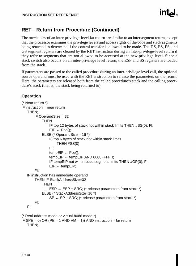
INSTRUCTION SET REFERENCE
proce-
RET—Return from Procedure (Continued)
The mechanics of an inter-privilege-level far return are similar to an intersegment return, exceptthat the processor examines the privilege levels and access rights of the code and stack segmentsbeing returned to determine if the control transfer is allowed to be made. The DS, ES, FS, andGS segment registers are cleared by the RET instruction during an inter-privilege-level return ifthey refer to segments that are not allowed to be accessed at the new privilege level. Since astack switch also occurs on an inter-privilege level return, the ESP and SS registers are loadedfrom the stack.
If parameters are passed to the called procedure during an inter-privilege level call, the optionalsource operand must be used with the RET instruction to release the parameters on the return.Here, the parameters are released both from the called procedure’s stack and the callingdure’s stack (that is, the stack being returned to).
Operation
(* Near return *)IF instruction = near return
THEN;IF OperandSize = 32
THENIF top 12 bytes of stack not within stack limits THEN #SS(0); FI;EIP ← Pop();
ELSE (* OperandSize = 16 *)IF top 6 bytes of stack not within stack limits
THEN #SS(0)FI;tempEIP ← Pop();tempEIP ← tempEIP AND 0000FFFFH;IF tempEIP not within code segment limits THEN #GP(0); FI;EIP ← tempEIP;
FI;IF instruction has immediate operand
THEN IF StackAddressSize=32THEN
ESP ← ESP + SRC; (* release parameters from stack *)ELSE (* StackAddressSize=16 *)
SP ← SP + SRC; (* release parameters from stack *)FI;
FI;
(* Real-address mode or virtual-8086 mode *)IF ((PE = 0) OR (PE = 1 AND VM = 1)) AND instruction = far return
THEN;
3-610

INSTRUCTION SET REFERENCE
RET—Return from Procedure (Continued)
IF OperandSize = 32THEN
IF top 12 bytes of stack not within stack limits THEN #SS(0); FI;EIP ← Pop();CS ← Pop(); (* 32-bit pop, high-order 16 bits discarded *)
ELSE (* OperandSize = 16 *)IF top 6 bytes of stack not within stack limits THEN #SS(0); FI;tempEIP ← Pop();tempEIP ← tempEIP AND 0000FFFFH;IF tempEIP not within code segment limits THEN #GP(0); FI;EIP ← tempEIP;CS ← Pop(); (* 16-bit pop *)
FI;IF instruction has immediate operand
THEN SP ← SP + (SRC AND FFFFH); (* release parameters from stack *)
FI;FI;
(* Protected mode, not virtual-8086 mode *)IF (PE = 1 AND VM = 0) AND instruction = far RET
THENIF OperandSize = 32
THEN IF second doubleword on stack is not within stack limits THEN #SS(0); FI;
ELSE (* OperandSize = 16 *)IF second word on stack is not within stack limits THEN #SS(0); FI;
FI;IF return code segment selector is null THEN GP(0); FI;IF return code segment selector addrsses descriptor beyond diescriptor table limit
THEN GP(selector; FI;Obtain descriptor to which return code segment selector points from descriptor tableIF return code segment descriptor is not a code segment THEN #GP(selector); FI;if return code segment selector RPL < CPL THEN #GP(selector); FI;IF return code segment descriptor is conforming
AND return code segment DPL > return code segment selector RPLTHEN #GP(selector); FI;
IF return code segment descriptor is not present THEN #NP(selector); FI:IF return code segment selector RPL > CPL
THEN GOTO RETURN-OUTER-PRIVILEGE-LEVEL;ELSE GOTO RETURN-TO-SAME-PRIVILEGE-LEVEL
FI;END;FI;
3-611

INSTRUCTION SET REFERENCE
RET—Return from Procedure (Continued)
RETURN-SAME-PRIVILEGE-LEVEL:IF the return instruction pointer is not within ther return code segment limit
THEN #GP(0); FI;IF OperandSize=32
THENEIP ← Pop();CS ← Pop(); (* 32-bit pop, high-order 16 bits discarded *)ESP ← ESP + SRC; (* release parameters from stack *)
ELSE (* OperandSize=16 *)EIP ← Pop();EIP ← EIP AND 0000FFFFH;CS ← Pop(); (* 16-bit pop *)ESP ← ESP + SRC; (* release parameters from stack *)
FI;
RETURN-OUTER-PRIVILEGE-LEVEL:IF top (16 + SRC) bytes of stack are not within stack limits (OperandSize=32)
OR top (8 + SRC) bytes of stack are not within stack limits (OperandSize=16)THEN #SS(0); FI;
FI;Read return segment selector;IF stack segment selector is null THEN #GP(0); FI;IF return stack segment selector index is not within its descriptor table limits
THEN #GP(selector); FI;Read segment descriptor pointed to by return segment selector;IF stack segment selector RPL ≠ RPL of the return code segment selector
OR stack segment is not a writable data segmentOR stack segment descriptor DPL ≠ RPL of the return code segment selector
THEN #GP(selector); FI;IF stack segment not present THEN #SS(StackSegmentSelector); FI;
IF the return instruction pointer is not within the return code segment limit THEN #GP(0); FI: CPL ← ReturnCodeSegmentSelector(RPL);IF OperandSize=32
THENEIP ← Pop();CS ← Pop(); (* 32-bit pop, high-order 16 bits discarded *) (* segment descriptor information also loaded *)CS(RPL) ← CPL;ESP ← ESP + SRC; (* release parameters from called procedure’s stack *)tempESP ← Pop();tempSS ← Pop(); (* 32-bit pop, high-order 16 bits discarded *) (* segment descriptor information also loaded *)ESP ← tempESP;SS ← tempSS;
3-612
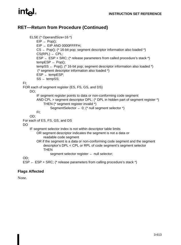
INSTRUCTION SET REFERENCE
RET—Return from Procedure (Continued)
ELSE (* OperandSize=16 *)EIP ← Pop();EIP ← EIP AND 0000FFFFH;CS ← Pop(); (* 16-bit pop; segment descriptor information also loaded *)CS(RPL) ← CPL;ESP ← ESP + SRC; (* release parameters from called procedure’s stack *)tempESP ← Pop();tempSS ← Pop(); (* 16-bit pop; segment descriptor information also loaded *) (* segment descriptor information also loaded *)ESP ← tempESP;SS ← tempSS;
FI;FOR each of segment register (ES, FS, GS, and DS)
DO;IF segment register points to data or non-conforming code segmentAND CPL > segment descriptor DPL; (* DPL in hidden part of segment register *)
THEN (* segment register invalid *)SegmentSelector ← 0; (* null segment selector *)
FI;OD;
For each of ES, FS, GS, and DSDO
IF segment selector index is not within descriptor table limitsOR segment descriptor indicates the segment is not a data or
readable code segmentOR if the segment is a data or non-conforming code segment and the segment
descriptor’s DPL < CPL or RPL of code segment’s segment selectorTHEN
segment selector register ← null selector;OD;ESP ← ESP + SRC; (* release parameters from calling procedure’s stack *)
Flags Affected
None.
3-613
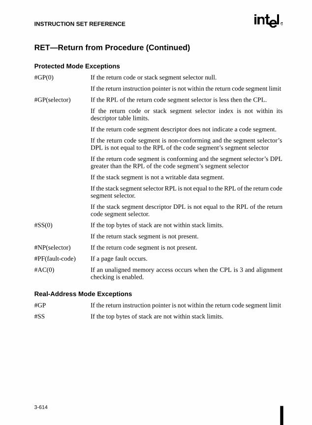
INSTRUCTION SET REFERENCE
tor’s
DPL
code
turn
ment
mit
RET—Return from Procedure (Continued)
Protected Mode Exceptions
#GP(0) If the return code or stack segment selector null.
If the return instruction pointer is not within the return code segment limit
#GP(selector) If the RPL of the return code segment selector is less then the CPL.
If the return code or stack segment selector index is not within itsdescriptor table limits.
If the return code segment descriptor does not indicate a code segment.
If the return code segment is non-conforming and the segment selecDPL is not equal to the RPL of the code segment’s segment selector
If the return code segment is conforming and the segment selector’s greater than the RPL of the code segment’s segment selector
If the stack segment is not a writable data segment.
If the stack segment selector RPL is not equal to the RPL of the return segment selector.
If the stack segment descriptor DPL is not equal to the RPL of the recode segment selector.
#SS(0) If the top bytes of stack are not within stack limits.
If the return stack segment is not present.
#NP(selector) If the return code segment is not present.
#PF(fault-code) If a page fault occurs.
#AC(0) If an unaligned memory access occurs when the CPL is 3 and alignchecking is enabled.
Real-Address Mode Exceptions
#GP If the return instruction pointer is not within the return code segment li
#SS If the top bytes of stack are not within stack limits.
3-614

INSTRUCTION SET REFERENCE
RET—Return from Procedure (Continued)
Virtual-8086 Mode Exceptions
#GP(0) If the return instruction pointer is not within the return code segment limit
#SS(0) If the top bytes of stack are not within stack limits.
#PF(fault-code) If a page fault occurs.
#AC(0) If an unaligned memory access occurs when alignment checking isenabled.
3-615
INSTRUCTION SET REFERENCE
ROL/ROR—Rotate
Refer to entry for RCL/RCR/ROL/ROR—Rotate.
3-616

INSTRUCTION SET REFERENCE
SMM.tdown
base
RSM—Resume from System Management Mode
Description
This instruction returns program control from system management mode (SMM) to the applica-tion program or operating-system procedure that was interrupted when the processor receivedan SSM interrupt. The processor’s state is restored from the dump created upon enteringIf the processor detects invalid state information during state restoration, it enters the shustate. The following invalid information can cause a shutdown:
• Any reserved bit of CR4 is set to 1.
• Any illegal combination of bits in CR0, such as (PG=1 and PE=0) or (NW=1 and CD=0).
• (Intel Pentium® and Intel486™ processors only.) The value stored in the state dump field is not a 32-KByte aligned address.
The contents of the model-specific registers are not affected by a return from SMM.
Refer to Chapter 11, System Management Mode (SMM), in the Intel Architecture SoftwareDeveloper’s Manual, Volume 3, for more information about SMM and the behavior of the RSMinstruction.
Operation
ReturnFromSSM;ProcessorState ← Restore(SSMDump);
Flags Affected
All.
Protected Mode Exceptions
#UD If an attempt is made to execute this instruction when the processor is notin SMM.
Real-Address Mode Exceptions
#UD If an attempt is made to execute this instruction when the processor is notin SMM.
Virtual-8086 Mode Exceptions
#UD If an attempt is made to execute this instruction when the processor is notin SMM.
Opcode Instruction Description
0F AA RSM Resume operation of interrupted program
3-617

INSTRUCTION SET REFERENCE
RSQRTPS—Packed Single-FP Square Root Reciprocal
Description
RSQRTPS returns an approximation of the reciprocal of the square root of the SP FP numbersfrom xmm2/m128. The maximum error for this approximation is:
|Error| <= 1.5x2-12
Figure 3-88. Operation of the RSQRTPS Instruction
Operation
DEST[31-0] = APPROX (1.0/SQRT(SRC/m128[31-0]));DEST[63-32] = APPROX (1.0/SQRT(SRC/m128[63-32]));DEST[95-64] = APPROX (1.0/SQRT(SRC/m128[95-64]));DEST[127-96] = APPROX (1.0/SQRT(SRC/m128[127-96]));
Intel C/C++ Compiler Intrinsic Equivalent
__m128 _mm_rsqrt_ps(__m128 a)
Computes the approximations of the reciprocals of the square roots of the four SP FP values of a.
Opcode Instruction Description
0F,52,/r RSQRTPS xmm1, xmm2/m128
Return a packed approximation of the square root of the reciprocal of XMM2/Mem.
Xmm1
Xmm1
RSQRTPS xmm1,xmm2/m128
Xmm2/m128 0.0007716 0.0086553
36.0
= = = =
3-618

INSTRUCTION SET REFERENCE
RSQRTPS—Packed Single-FP Square Root Reciprocal (Continued)
Exceptions
General protection exception if not aligned on 16-byte boundary, regardless of segment.
Numeric Exceptions
None.
Protected Mode Exceptions
#GP(0) For an illegal memory operand effective address in the CS, DS, ES, FS, orGS segments.
#SS(0) For an illegal address in the SS segment.
#PF(fault-code) For a page fault.
#UD If CR0.EM = 1.
#NM If TS bit in CR0 is set.
#UD If CR4.OSFXSR(bit 9) = 0.
#UD If CPUID.XMM(EDX bit 25) = 0.
Real Address Mode Exceptions
Interrupt 13 If any part of the operand would lie outside of the effective address spacefrom 0 to 0FFFFH.
#UD If CR0.EM = 1.
#NM If TS bit in CR0 is set.
#UD If CR4.OSFXSR(bit 9) = 0.
#UD If CPUID.XMM(EDX bit 25) = 0.
Virtual 8086 Mode Exceptions
Same exceptions as in Real Address Mode.
#PF(fault-code) For a page fault.
Comments
RSQRTPS is not affected by the rounding control in MXCSR. Denormal inputs are treated aszeroes (of the same sign) and underflow results are always flushed to zero, with the sign of theoperand.
3-619

INSTRUCTION SET REFERENCE
RSQRTSS—Scalar Single-FP Square Root Reciprocal
Description
RSQRTSS returns an approximation of the reciprocal of the square root of the lowest SP FPnumber from xmm2/m32; the upper three fields are passed through from xmm1. The maximumerror for this approximation is:
|Error| <= 1.5x2-12
Figure 3-89. Operation of the RSQRTSS Instruction
Operation
DEST[31-0] = APPROX (1.0/SQRT(SRC/m32[31-0]));DEST[63-32] = DEST[63-32];DEST[95-64] = DEST[95-64];DEST[127-96] = DEST[127-96];
Opcode Instruction Description
F3,0F,52,/r RSQRTSS xmm1, xmm2/m32
Return an approximation of the square root of the reciprocal of the lowest SP FP number in XMM2/Mem.
Xmm1
Xmm2/m32
Xmm1
RSQRTSS xmm1, xmm2/m32
=
3-620

INSTRUCTION SET REFERENCE
RSQRTSS—Scalar Single-FP Square Root Reciprocal (Continued)
Intel C/C++ Compiler Intrinsic Equivalent
__m128 _mm_rsqrt_ss(__m128 a)
Computes the approximation of the reciprocal of the square root of the lower SP FP value of a;the upper three SP FP values are passed through.
Numeric Exceptions
None.
Protected Mode Exceptions
#GP(0) For an illegal memory operand effective address in the CS, DS, ES, FS, orGS segments.
#SS(0) For an illegal address in the SS segment.
#PF (fault-code) For a page fault.
#UD If CR0.EM = 1.
#NM If TS bit in CR0 is set.
#AC For unaligned memory reference. To enable #AC exceptions, three condi-tions must be true(CR0.AM is set; EFLAGS.AC is set; current CPL is 3)
Real Address Mode Exceptions
Interrupt 13 If any part of the operand would lie outside of the effective address spacefrom 0 to 0FFFFH.
#UD If CR0.EM = 1.
#NM If TS bit in CR0 is set.
Virtual 8086 Mode Exceptions
Same exceptions as in Real Address Mode.
#AC For unaligned memory reference if the current privilege level is 3.
#PF (fault-code) For a page fault.
Comments
RSQRTSS is not affected by the rounding control in MXCSR. Denormal inputs are treated aszeroes (of the same sign) and underflow results are always flushed to zero, with the sign of theoperand.
3-621

INSTRUCTION SET REFERENCE
and 5ly.
SAHF—Store AH into Flags
Description
This instruction loads the SF, ZF, AF, PF, and CF flags of the EFLAGS register with values fromthe corresponding bits in the AH register (bits 7, 6, 4, 2, and 0, respectively). Bits 1, 3, and 5 ofregister AH are ignored; the corresponding reserved bits (1, 3, and 5) in the EFLAGS registerremain as shown in the “Operation” section below.
Operation
EFLAGS(SF:ZF:0:AF:0:PF:1:CF) ← AH;
Flags Affected
The SF, ZF, AF, PF, and CF flags are loaded with values from the AH register. Bits 1, 3, of the EFLAGS register are unaffected, with the values remaining 1, 0, and 0, respective
Exceptions (All Operating Modes)
None.
Opcode Instruction Clocks Description
9E SAHF 2 Loads SF, ZF, AF, PF, and CF from AH into EFLAGS register
3-622

INSTRUCTION SET REFERENCE
SAL/SAR/SHL/SHR—Shift
NOTE:
* Not the same form of division as IDIV; rounding is toward negative infinity.
Opcode Instruction Description
D0 /4 SAL r/m8,1 Multiply r/m8 by 2, once
D2 /4 SAL r/m8,CL Multiply r/m8 by 2, CL times
C0 /4 ib SAL r/m8,imm8 Multiply r/m8 by 2, imm8 times
D1 /4 SAL r/m16,1 Multiply r/m16 by 2, once
D3 /4 SAL r/m16,CL Multiply r/m16 by 2, CL times
C1 /4 ib SAL r/m16,imm8 Multiply r/m16 by 2, imm8 times
D1 /4 SAL r/m32,1 Multiply r/m32 by 2, once
D3 /4 SAL r/m32,CL Multiply r/m32 by 2, CL times
C1 /4 ib SAL r/m32,imm8 Multiply r/m32 by 2, imm8 times
D0 /7 SAR r/m8,1 Signed divide* r/m8 by 2, once
D2 /7 SAR r/m8,CL Signed divide* r/m8 by 2, CL times
C0 /7 ib SAR r/m8,imm8 Signed divide* r/m8 by 2, imm8 times
D1 /7 SAR r/m16,1 Signed divide* r/m16 by 2, once
D3 /7 SAR r/m16,CL Signed divide* r/m16 by 2, CL times
C1 /7 ib SAR r/m16,imm8 Signed divide* r/m16 by 2, imm8 times
D1 /7 SAR r/m32,1 Signed divide* r/m32 by 2, once
D3 /7 SAR r/m32,CL Signed divide* r/m32 by 2, CL times
C1 /7 ib SAR r/m32,imm8 Signed divide* r/m32 by 2, imm8 times
D0 /4 SHL r/m8,1 Multiply r/m8 by 2, once
D2 /4 SHL r/m8,CL Multiply r/m8 by 2, CL times
C0 /4 ib SHL r/m8,imm8 Multiply r/m8 by 2, imm8 times
D1 /4 SHL r/m16,1 Multiply r/m16 by 2, once
D3 /4 SHL r/m16,CL Multiply r/m16 by 2, CL times
C1 /4 ib SHL r/m16,imm8 Multiply r/m16 by 2, imm8 times
D1 /4 SHL r/m32,1 Multiply r/m32 by 2, once
D3 /4 SHL r/m32,CL Multiply r/m32 by 2, CL times
C1 /4 ib SHL r/m32,imm8 Multiply r/m32 by 2, imm8 times
D0 /5 SHR r/m8,1 Unsigned divide r/m8 by 2, once
D2 /5 SHR r/m8,CL Unsigned divide r/m8 by 2, CL times
C0 /5 ib SHR r/m8,imm8 Unsigned divide r/m8 by 2, imm8 times
D1 /5 SHR r/m16,1 Unsigned divide r/m16 by 2, once
D3 /5 SHR r/m16,CL Unsigned divide r/m16 by 2, CL times
C1 /5 ib SHR r/m16,imm8 Unsigned divide r/m16 by 2, imm8 times
D1 /5 SHR r/m32,1 Unsigned divide r/m32 by 2, once
D3 /5 SHR r/m32,CL Unsigned divide r/m32 by 2, CL times
C1 /5 ib SHR r/m32,imm8 Unsigned divide r/m32 by 2, imm8 times
3-623

INSTRUCTION SET REFERENCE
iftedapter
e isividet by
ly the
ost-iginallearedf the
SAL/SAR/SHL/SHR—Shift (Continued)
Description
These instructions shift the bits in the first operand (destination operand) to the left or right bythe number of bits specified in the second operand (count operand). Bits shifted beyond thedestination operand boundary are first shifted into the CF flag, then discarded. At the end of theshift operation, the CF flag contains the last bit shifted out of the destination operand.
The destination operand can be a register or a memory location. The count operand can be animmediate value or register CL. The count is masked to five bits, which limits the count rangeto 0 to 31. A special opcode encoding is provided for a count of 1.
The shift arithmetic left (SAL) and shift logical left (SHL) instructions perform the same oper-ation; they shift the bits in the destination operand to the left (toward more significant bit loca-tions). For each shift count, the most significant bit of the destination operand is shifted into theCF flag, and the least significant bit is cleared. Refer to Figure 6-6 in Chapter 6, Instruction SetSummary of the Intel Architecture Software Developer’s Manual, Volume 1.
The shift arithmetic right (SAR) and shift logical right (SHR) instructions shift the bits of thedestination operand to the right (toward less significant bit locations). For each shift count, theleast significant bit of the destination operand is shifted into the CF flag, and the most significantbit is either set or cleared depending on the instruction type. The SHR instruction clears the mostsignificant bit. For more information, refer to Figure 6-7 in Chapter 6, Instruction Set Summaryof the Intel Architecture Software Developer’s Manual, Volume 1. The SAR instruction sets orclears the most significant bit to correspond to the sign (most significant bit) of the original valuein the destination operand. In effect, the SAR instruction fills the empty bit position’s shvalue with the sign of the unshifted value. For more information, refer to Figure 6-8 in Ch6, Instruction Set Summary of the Intel Architecture Software Developer’s Manual, Volume 1.
The SAR and SHR instructions can be used to perform signed or unsigned division, respectively,of the destination operand by powers of 2. For example, using the SAR instruction to shift asigned integer one bit to the right divides the value by 2.
Using the SAR instruction to perform a division operation does not produce the same result asthe IDIV instruction. The quotient from the IDIV instruction is rounded toward zero, whereasthe “quotient” of the SAR instruction is rounded toward negative infinity. This differencapparent only for negative numbers. For example, when the IDIV instruction is used to d-9 by 4, the result is -2 with a remainder of -1. If the SAR instruction is used to shift -9 rightwo bits, the result is -3 and the “remainder” is +3; however, the SAR instruction stores onmost significant bit of the remainder (in the CF flag).
The OF flag is affected only on 1-bit shifts. For left shifts, the OF flag is cleared to 0 if the msignificant bit of the result is the same as the CF flag (that is, the top two bits of the oroperand were the same); otherwise, it is set to 1. For the SAR instruction, the OF flag is cfor all 1-bit shifts. For the SHR instruction, the OF flag is set to the most-significant bit ooriginal operand.
3-624

INSTRUCTION SET REFERENCE
SAL/SAR/SHL/SHR—Shift (Continued)
Intel Architecture Compatibility
The 8086 does not mask the shift count. However, all other Intel Architecture processors(starting with the Intel 286 processor) do mask the shift count to five bits, resulting in amaximum count of 31. This masking is done in all operating modes (including the virtual-8086mode) to reduce the maximum execution time of the instructions.
Operation
tempCOUNT ← (COUNT AND 1FH);tempDEST ← DEST;WHILE (tempCOUNT ≠ 0)DO
IF instruction is SAL or SHLTHEN
CF ← MSB(DEST);ELSE (* instruction is SAR or SHR *)
CF ← LSB(DEST);FI;IF instruction is SAL or SHL
THEN DEST ← DEST ∗ 2;
ELSE IF instruction is SAR
THEN DEST ← DEST / 2 (*Signed divide, rounding toward negative infinity*);
ELSE (* instruction is SHR *)DEST ← DEST / 2 ; (* Unsigned divide *);
FI;FI;tempCOUNT ← tempCOUNT – 1;
OD;(* Determine overflow for the various instructions *)IF COUNT = 1
THENIF instruction is SAL or SHL
THEN OF ← MSB(DEST) XOR CF;
ELSE IF instruction is SAR
THEN OF ← 0;
ELSE (* instruction is SHR *)OF ← MSB(tempDEST);
FI;FI;
3-625

INSTRUCTION SET REFERENCE
ion”t. If the
S, or
it.
ce is
S, or
it.
SAL/SAR/SHL/SHR—Shift (Continued)
ELSE IF COUNT = 0THEN
All flags remain unchanged;ELSE (* COUNT neither 1 or 0 *)
OF ← undefined;FI;
FI;
Flags Affected
The CF flag contains the value of the last bit shifted out of the destination operand; it is unde-fined for SHL and SHR instructions where the count is greater than or equal to the size (in bits)of the destination operand. The OF flag is affected only for 1-bit shifts (refer to “Descriptabove); otherwise, it is undefined. The SF, ZF, and PF flags are set according to the resulcount is 0, the flags are not affected. For a non-zero count, the AF flag is undefined.
Protected Mode Exceptions
#GP(0) If the destination is located in a nonwritable segment.
If a memory operand effective address is outside the CS, DS, ES, FGS segment limit.
If the DS, ES, FS, or GS register contains a null segment selector.
#SS(0) If a memory operand effective address is outside the SS segment lim
#PF(fault-code) If a page fault occurs.
#AC(0) If alignment checking is enabled and an unaligned memory referenmade while the current privilege level is 3.
Real-Address Mode Exceptions
#GP If a memory operand effective address is outside the CS, DS, ES, FGS segment limit.
#SS If a memory operand effective address is outside the SS segment lim
3-626
INSTRUCTION SET REFERENCE
SAL/SAR/SHL/SHR—Shift (Continued)
Virtual-8086 Mode Exceptions
#GP(0) If a memory operand effective address is outside the CS, DS, ES, FS, orGS segment limit.
#SS(0) If a memory operand effective address is outside the SS segment limit.
#PF(fault-code) If a page fault occurs.
#AC(0) If alignment checking is enabled and an unaligned memory reference ismade.
3-627

INSTRUCTION SET REFERENCE
SBB—Integer Subtraction with Borrow
Description
This instruction adds the source operand (second operand) and the carry (CF) flag, and subtractsthe result from the destination operand (first operand). The result of the subtraction is stored inthe destination operand. The destination operand can be a register or a memory location; thesource operand can be an immediate, a register, or a memory location. (However, two memoryoperands cannot be used in one instruction.) The state of the CF flag represents a borrow froma previous subtraction.
When an immediate value is used as an operand, it is sign-extended to the length of the destina-tion operand format.
The SBB instruction does not distinguish between signed or unsigned operands. Instead, theprocessor evaluates the result for both data types and sets the OF and CF flags to indicate aborrow in the signed or unsigned result, respectively. The SF flag indicates the sign of the signedresult.
The SBB instruction is usually executed as part of a multibyte or multiword subtraction in whicha SUB instruction is followed by a SBB instruction.
Operation
DEST ← DEST – (SRC + CF);
Flags Affected
The OF, SF, ZF, AF, PF, and CF flags are set according to the result.
Opcode Instruction Description
1C ib SBB AL,imm8 Subtract with borrow imm8 from AL
1D iw SBB AX,imm16 Subtract with borrow imm16 from AX
1D id SBB EAX,imm32 Subtract with borrow imm32 from EAX
80 /3 ib SBB r/m8,imm8 Subtract with borrow imm8 from r/m8
81 /3 iw SBB r/m16,imm16 Subtract with borrow imm16 from r/m16
81 /3 id SBB r/m32,imm32 Subtract with borrow imm32 from r/m32
83 /3 ib SBB r/m16,imm8 Subtract with borrow sign-extended imm8 from r/m16
83 /3 ib SBB r/m32,imm8 Subtract with borrow sign-extended imm8 from r/m32
18 /r SBB r/m8,r8 Subtract with borrow r8 from r/m8
19 /r SBB r/m16,r16 Subtract with borrow r16 from r/m16
19 /r SBB r/m32,r32 Subtract with borrow r32 from r/m32
1A /r SBB r8,r/m8 Subtract with borrow r/m8 from r8
1B /r SBB r16,r/m16 Subtract with borrow r/m16 from r16
1B /r SBB r32,r/m32 Subtract with borrow r/m32 from r32
3-628

INSTRUCTION SET REFERENCE
SBB—Integer Subtraction with Borrow (Continued)
Protected Mode Exceptions
#GP(0) If the destination is located in a nonwritable segment.
If a memory operand effective address is outside the CS, DS, ES, FS, orGS segment limit.
If the DS, ES, FS, or GS register contains a null segment selector.
#SS(0) If a memory operand effective address is outside the SS segment limit.
#PF(fault-code) If a page fault occurs.
#AC(0) If alignment checking is enabled and an unaligned memory reference ismade while the current privilege level is 3.
Real-Address Mode Exceptions
#GP If a memory operand effective address is outside the CS, DS, ES, FS, orGS segment limit.
#SS If a memory operand effective address is outside the SS segment limit.
Virtual-8086 Mode Exceptions
#GP(0) If a memory operand effective address is outside the CS, DS, ES, FS, orGS segment limit.
#SS(0) If a memory operand effective address is outside the SS segment limit.
#PF(fault-code) If a page fault occurs.
#AC(0) If alignment checking is enabled and an unaligned memory reference ismade.
3-629

INSTRUCTION SET REFERENCE
nds”AS
erandegisteregisterThisenta-pecifyecifyt be
of theL, AX,electedSD
ordinger isncre-ur for
fix forstruc- status
PNEfix.
SCAS/SCASB/SCASW/SCASD—Scan String
Description
These instructions compare the byte, word, or double word specified with the memory operandwith the value in the AL, AX, or EAX register, and sets the status flags in the EFLAGS registeraccording to the results. The memory operand address is read from either the ES:EDI or theES:DI registers (depending on the address-size attribute of the instruction, 32 or 16, respec-tively). The ES segment cannot be overridden with a segment override prefix.
At the assembly-code level, two forms of this instruction are allowed: the “explicit-operaform and the “no-operands” form. The explicit-operand form (specified with the SCmnemonic) allows the memory operand to be specified explicitly. Here, the memory opshould be a symbol that indicates the size and location of the operand value. The roperand is then automatically selected to match the size of the memory operand (the AL rfor byte comparisons, AX for word comparisons, and EAX for doubleword comparisons). explicit-operand form is provided to allow documentation; however, note that the documtion provided by this form can be misleading. That is, the memory operand symbol must sthe correct type (size) of the operand (byte, word, or doubleword), but it does not have to spthe correct location. The location is always specified by the ES:(E)DI registers, which musloaded correctly before the compare string instruction is executed.
The no-operands form provides “short forms” of the byte, word, and doubleword versions SCAS instructions. Here also ES:(E)DI is assumed to be the memory operand and the Aor EAX register is assumed to be the register operand. The size of the two operands is swith the mnemonic: SCASB (byte comparison), SCASW (word comparison), or SCA(doubleword comparison).
After the comparison, the (E)DI register is incremented or decremented automatically accto the setting of the DF flag in the EFLAGS register. (If the DF flag is 0, the (E)DI registincremented; if the DF flag is 1, the (E)DI register is decremented.) The (E)DI register is imented or decremented by one for byte operations, by two for word operations, or by fodoubleword operations.
The SCAS, SCASB, SCASW, and SCASD instructions can be preceded by the REP preblock comparisons of ECX bytes, words, or doublewords. More often, however, these intions will be used in a LOOP construct that takes some action based on the setting of theflags before the next comparison is made. Refer to “REP/REPE/REPZ/RE/REPNZ—Repeat String Operation Prefix” in this chapter for a description of the REP pre
Opcode Instruction Description
AE SCAS m8 Compare AL with byte at ES:(E)DI and set status flags
AF SCAS m16 Compare AX with word at ES:(E)DI and set status flags
AF SCAS m32 Compare EAX with doubleword at ES(E)DI and set status flags
AE SCASB Compare AL with byte at ES:(E)DI and set status flags
AF SCASW Compare AX with word at ES:(E)DI and set status flags
AF SCASD Compare EAX with doubleword at ES:(E)DI and set status flags
3-630

INSTRUCTION SET REFERENCE
SCAS/SCASB/SCASW/SCASD—Scan String (Continued)
Operation
IF (byte cmparison)THEN
temp ← AL − SRC;SetStatusFlags(temp);
THEN IF DF = 0THEN (E)DI ← (E)DI + 1; ELSE (E)DI ← (E)DI – 1;
FI;ELSE IF (word comparison)
THENtemp ← AX − SRC;SetStatusFlags(temp)
THEN IF DF = 0THEN (E)DI ← (E)DI + 2; ELSE (E)DI ← (E)DI – 2;
FI;ELSE (* doubleword comparison *)
temp ← EAX − SRC;SetStatusFlags(temp)
THEN IF DF = 0THEN (E)DI ← (E)DI + 4; ELSE (E)DI ← (E)DI – 4;
FI;FI;
FI;
Flags Affected
The OF, SF, ZF, AF, PF, and CF flags are set according to the temporary result of the comparison.
Protected Mode Exceptions
#GP(0) If a memory operand effective address is outside the limit of the ESsegment.
If the ES register contains a null segment selector.
If an illegal memory operand effective address in the ES segment is given.
#PF(fault-code) If a page fault occurs.
#AC(0) If alignment checking is enabled and an unaligned memory reference ismade while the current privilege level is 3.
3-631

INSTRUCTION SET REFERENCE
SCAS/SCASB/SCASW/SCASD—Scan String (Continued)
Real-Address Mode Exceptions
#GP If a memory operand effective address is outside the CS, DS, ES, FS, orGS segment limit.
#SS If a memory operand effective address is outside the SS segment limit.
Virtual-8086 Mode Exceptions
#GP(0) If a memory operand effective address is outside the CS, DS, ES, FS, orGS segment limit.
#SS(0) If a memory operand effective address is outside the SS segment limit.
#PF(fault-code) If a page fault occurs.
#AC(0) If alignment checking is enabled and an unaligned memory reference ismade.
3-632

INSTRUCTION SET REFERENCE
nship the SF
SETcc—Set Byte on Condition
Description
This instruction sets the destination operand to 0 or 1 depending on the settings of the status flags(CF, SF, OF, ZF, and PF) in the EFLAGS register. The destination operand points to a byteregister or a byte in memory. The condition code suffix (cc) indicates the condition being testedfor.
The terms “above” and “below” are associated with the CF flag and refer to the relatiobetween two unsigned integer values. The terms “greater” and “less” are associated withand OF flags and refer to the relationship between two signed integer values.
Opcode Instruction Description
0F 97 SETA r/m8 Set byte if above (CF=0 and ZF=0)
0F 93 SETAE r/m8 Set byte if above or equal (CF=0)
0F 92 SETB r/m8 Set byte if below (CF=1)
0F 96 SETBE r/m8 Set byte if below or equal (CF=1 or ZF=1)
0F 92 SETC r/m8 Set if carry (CF=1)
0F 94 SETE r/m8 Set byte if equal (ZF=1)
0F 9F SETG r/m8 Set byte if greater (ZF=0 and SF=OF)
0F 9D SETGE r/m8 Set byte if greater or equal (SF=OF)
0F 9C SETL r/m8 Set byte if less (SF<>OF)
0F 9E SETLE r/m8 Set byte if less or equal (ZF=1 or SF<>OF)
0F 96 SETNA r/m8 Set byte if not above (CF=1 or ZF=1)
0F 92 SETNAE r/m8 Set byte if not above or equal (CF=1)
0F 93 SETNB r/m8 Set byte if not below (CF=0)
0F 97 SETNBE r/m8 Set byte if not below or equal (CF=0 and ZF=0)
0F 93 SETNC r/m8 Set byte if not carry (CF=0)
0F 95 SETNE r/m8 Set byte if not equal (ZF=0)
0F 9E SETNG r/m8 Set byte if not greater (ZF=1 or SF<>OF)
0F 9C SETNGE r/m8 Set if not greater or equal (SF<>OF)
0F 9D SETNL r/m8 Set byte if not less (SF=OF)
0F 9F SETNLE r/m8 Set byte if not less or equal (ZF=0 and SF=OF)
0F 91 SETNO r/m8 Set byte if not overflow (OF=0)
0F 9B SETNP r/m8 Set byte if not parity (PF=0)
0F 99 SETNS r/m8 Set byte if not sign (SF=0)
0F 95 SETNZ r/m8 Set byte if not zero (ZF=0)
0F 90 SETO r/m8 Set byte if overflow (OF=1)
0F 9A SETP r/m8 Set byte if parity (PF=1)
0F 9A SETPE r/m8 Set byte if parity even (PF=1)
0F 9B SETPO r/m8 Set byte if parity odd (PF=0)
0F 98 SETS r/m8 Set byte if sign (SF=1)
0F 94 SETZ r/m8 Set byte if zero (ZF=1)
3-633

INSTRUCTION SET REFERENCE
SETcc—Set Byte on Condition (Continued)
Many of the SETcc instruction opcodes have alternate mnemonics. For example, the SETG (setbyte if greater) and SETNLE (set if not less or equal) both have the same opcode and test for thesame condition: ZF equals 0 and SF equals OF. These alternate mnemonics are provided to makecode more intelligible. Appendix B, EFLAGS Condition Codes, in the Intel Architecture Soft-ware Developer’s Manual, Volume 1, shows the alternate mnemonics for various test conditions.
Some languages represent a logical one as an integer with all bits set. This representation can beobtained by choosing the logically opposite condition for the SETcc instruction, then decre-menting the result. For example, to test for overflow, use the SETNO instruction, then decre-ment the result.
Operation
IF conditionTHEN DEST ← 1 ELSE DEST ← 0;
FI;
Flags Affected
None.
Protected Mode Exceptions
#GP(0) If the destination is located in a nonwritable segment.
If a memory operand effective address is outside the CS, DS, ES, FS, orGS segment limit.
If the DS, ES, FS, or GS register contains a null segment selector.
#SS(0) If a memory operand effective address is outside the SS segment limit.
#PF(fault-code) If a page fault occurs.
Real-Address Mode Exceptions
#GP If a memory operand effective address is outside the CS, DS, ES, FS, orGS segment limit.
#SS If a memory operand effective address is outside the SS segment limit.
Virtual-8086 Mode Exceptions
#GP(0) If a memory operand effective address is outside the CS, DS, ES, FS, orGS segment limit.
#SS(0) If a memory operand effective address is outside the SS segment limit.
#PF(fault-code) If a page fault occurs.
3-634

INSTRUCTION SET REFERENCE
SFENCE—Store Fence
Description
Weakly ordered memory types can enable higher performance through such techniques as out-of-order issue, write-combining, and write-collapsing. Memory ordering issues can arisebetween a producer and a consumer of data and there are a number of common usage modelswhich may be affected by weakly ordered stores:
1. library functions, which use weakly ordered memory to write results
2. compiler-generated code, which also benefit from writing weakly-ordered results
3. hand-written code
The degree to which a consumer of data knows that the data is weakly ordered can vary for thesecases. As a result, the SFENCE instruction provides a performance-efficient way of ensuringordering between routines that produce weakly-ordered results and routines that consume thisdata. The SFENCE is ordered with respect to stores and other SFENCE instructions.
SFENCE uses the following ModRM encoding:
Mod (7:6) = 11B
Reg/Opcode (5:3) = 111B
R/M (2:0) = 000B
All other ModRM encodings are defined to be reserved, and use of these encodings risks incom-patibility with future processors.
Operation
WHILE (NOT(preceding_stores_globally_visible)) WAIT();
Intel C/C++ Compiler Intrinsic Equivalent
void_mm_sfence(void)
Guarantees that every preceding store is globally visible before any subsequent store.
Numeric Exceptions
None.
Opcode Instruction Description
0F AE /7 SFENCE Guarantees that every store instruction that precedes in program order the store fence instruction is globally visible before any store instruction which follows the fence is globally visible.
3-635

INSTRUCTION SET REFERENCE
SFENCE—Store Fence (Continued)
Protected Mode Exceptions
None.
Real-Address Mode Exceptions
None.
Virtual-8086 Mode Exceptions
None.
Comments
SFENCE ignores the value of CR4.OSFXSR. SFENCE will not generate an invalid exceptionif CR4.OSFXSR = 0
3-636

INSTRUCTION SET REFERENCE
for
286ts with.
SGDT/SIDT—Store Global/Interrupt Descriptor Table Register
Description
These instructions store the contents of the global descriptor table register (GDTR) or the inter-rupt descriptor table register (IDTR) in the destination operand. The destination operand speci-fies a 6-byte memory location. If the operand-size attribute is 32 bits, the 16-bit limit field of theregister is stored in the lower two bytes of the memory location and the 32-bit base address isstored in the upper four bytes. If the operand-size attribute is 16 bits, the limit is stored in thelower two bytes and the 24-bit base address is stored in the third, fourth, and fifth byte, with thesixth byte filled with 0s.
The SGDT and SIDT instructions are only useful in operating-system software; however, theycan be used in application programs without causing an exception to be generated.
Refer to “LGDT/LIDT—Load Global/Interrupt Descriptor Table Register” in this chapter information on loading the GDTR and IDTR.
Intel Architecture Compatibility
The 16-bit forms of the SGDT and SIDT instructions are compatible with the Intel processor, if the upper eight bits are not referenced. The Intel 286 processor fills these bi1s; the Pentium® Pro, Pentium®, Intel486™, and Intel386™ processors fill these bits with 0s
Opcode Instruction Description
0F 01 /0 SGDT m Store GDTR to m
0F 01 /1 SIDT m Store IDTR to m
3-637

INSTRUCTION SET REFERENCE
SGDT/SIDT—Store Global/Interrupt Descriptor Table Register (Continued)
Operation
IF instruction is IDTRTHEN
IF OperandSize = 16THEN
DEST[0:15] ← IDTR(Limit);DEST[16:39] ← IDTR(Base); (* 24 bits of base address loaded; *)DEST[40:47] ← 0;
ELSE (* 32-bit Operand Size *)DEST[0:15] ← IDTR(Limit);DEST[16:47] ← IDTR(Base); (* full 32-bit base address loaded *)
FI;ELSE (* instruction is SGDT *)
IF OperandSize = 16THEN
DEST[0:15] ← GDTR(Limit);DEST[16:39] ← GDTR(Base); (* 24 bits of base address loaded; *)DEST[40:47] ← 0;
ELSE (* 32-bit Operand Size *)DEST[0:15] ← GDTR(Limit);DEST[16:47] ← GDTR(Base); (* full 32-bit base address loaded *)
FI; FI;
Flags Affected
None.
Protected Mode Exceptions
#UD If the destination operand is a register.
#GP(0) If the destination is located in a nonwritable segment.
If a memory operand effective address is outside the CS, DS, ES, FS, orGS segment limit.
If the DS, ES, FS, or GS register is used to access memory and it containsa null segment selector.
#SS(0) If a memory operand effective address is outside the SS segment limit.
#PF(fault-code) If a page fault occurs.
#AC(0) If an unaligned memory access occurs when the CPL is 3 and alignmentchecking is enabled.
3-638

INSTRUCTION SET REFERENCE
SGDT/SIDT—Store Global/Interrupt Descriptor Table Register (Continued)
Real-Address Mode Exceptions
#UD If the destination operand is a register.
#GP If a memory operand effective address is outside the CS, DS, ES, FS, orGS segment limit.
#SS If a memory operand effective address is outside the SS segment limit.
Virtual-8086 Mode Exceptions
#UD If the destination operand is a register.
#GP(0) If a memory operand effective address is outside the CS, DS, ES, FS, orGS segment limit.
#SS(0) If a memory operand effective address is outside the SS segment limit.
#PF(fault-code) If a page fault occurs.
#AC(0) If an unaligned memory access occurs when alignment checking isenabled.
3-639

INSTRUCTION SET REFERENCE
SHL/SHR—Shift Instructions
Refer to entry for SAL/SAR/SHL/SHR—Shift.
3-640

INSTRUCTION SET REFERENCE
SHLD—Double Precision Shift Left
Description
This instruction shifts the first operand (destination operand) to the left the number of bits spec-ified by the third operand (count operand). The second operand (source operand) provides bitsto shift in from the right (starting with bit 0 of the destination operand). The destination operandcan be a register or a memory location; the source operand is a register. The count operand is anunsigned integer that can be an immediate byte or the contents of the CL register. Only bits 0through 4 of the count are used, which masks the count to a value between 0 and 31. If the countis greater than the operand size, the result in the destination operand is undefined.
If the count is one or greater, the CF flag is filled with the last bit shifted out of the destinationoperand. For a 1-bit shift, the OF flag is set if a sign change occurred; otherwise, it is cleared. Ifthe count operand is 0, the flags are not affected.
The SHLD instruction is useful for multiprecision shifts of 64 bits or more.
Opcode Instruction Description
0F A4 SHLD r/m16,r16,imm8 Shift r/m16 to left imm8 places while shifting bits from r16 in from the right
0F A5 SHLD r/m16,r16,CL Shift r/m16 to left CL places while shifting bits from r16 in from the right
0F A4 SHLD r/m32,r32,imm8 Shift r/m32 to left imm8 places while shifting bits from r32 in from the right
0F A5 SHLD r/m32,r32,CL Shift r/m32 to left CL places while shifting bits from r32 in from the right
3-641

INSTRUCTION SET REFERENCE
SHLD—Double Precision Shift Left (Continued)
Operation
COUNT ← COUNT MOD 32;SIZE ← OperandSizeIF COUNT = 0
THEN no operation
ELSEIF COUNT ≥ SIZE
THEN (* Bad parameters *)DEST is undefined;CF, OF, SF, ZF, AF, PF are undefined;
ELSE (* Perform the shift *)CF ← BIT[DEST, SIZE – COUNT];(* Last bit shifted out on exit *)FOR i ← SIZE – 1 DOWNTO COUNTDO
Bit(DEST, i) ← Bit(DEST, i – COUNT);OD;FOR i ← COUNT – 1 DOWNTO 0DO
BIT[DEST, i] ← BIT[SRC, i – COUNT + SIZE];OD;
FI;FI;
Flags Affected
If the count is one or greater, the CF flag is filled with the last bit shifted out of the destinationoperand and the SF, ZF, and PF flags are set according to the value of the result. For a 1-bit shift,the OF flag is set if a sign change occurred; otherwise, it is cleared. For shifts greater than onebit, the OF flag is undefined. If a shift occurs, the AF flag is undefined. If the count operand is0, the flags are not affected. If the count is greater than the operand size, the flags are undefined.
3-642
INSTRUCTION SET REFERENCE
SHLD—Double Precision Shift Left (Continued)
Protected Mode Exceptions
#GP(0) If the destination is located in a nonwritable segment.
If a memory operand effective address is outside the CS, DS, ES, FS, orGS segment limit.
If the DS, ES, FS, or GS register contains a null segment selector.
#SS(0) If a memory operand effective address is outside the SS segment limit.
#PF(fault-code) If a page fault occurs.
#AC(0) If alignment checking is enabled and an unaligned memory reference ismade while the current privilege level is 3.
Real-Address Mode Exceptions
#GP If a memory operand effective address is outside the CS, DS, ES, FS, orGS segment limit.
#SS If a memory operand effective address is outside the SS segment limit.
Virtual-8086 Mode Exceptions
#GP(0) If a memory operand effective address is outside the CS, DS, ES, FS, orGS segment limit.
#SS(0) If a memory operand effective address is outside the SS segment limit.
#PF(fault-code) If a page fault occurs.
#AC(0) If alignment checking is enabled and an unaligned memory reference ismade.
3-643

INSTRUCTION SET REFERENCE
SHRD—Double Precision Shift Right
Description
This instruction shifts the first operand (destination operand) to the right the number of bits spec-ified by the third operand (count operand). The second operand (source operand) provides bitsto shift in from the left (starting with the most significant bit of the destination operand). Thedestination operand can be a register or a memory location; the source operand is a register. Thecount operand is an unsigned integer that can be an immediate byte or the contents of the CLregister. Only bits 0 through 4 of the count are used, which masks the count to a value between0 and 31. If the count is greater than the operand size, the result in the destination operand isundefined.
If the count is one or greater, the CF flag is filled with the last bit shifted out of the destinationoperand. For a 1-bit shift, the OF flag is set if a sign change occurred; otherwise, it is cleared. Ifthe count operand is 0, the flags are not affected.
The SHRD instruction is useful for multiprecision shifts of 64 bits or more.
Opcode Instruction Description
0F AC SHRD r/m16,r16,imm8 Shift r/m16 to right imm8 places while shifting bits from r16 in from the left
0F AD SHRD r/m16,r16,CL Shift r/m16 to right CL places while shifting bits from r16 in from the left
0F AC SHRD r/m32,r32,imm8 Shift r/m32 to right imm8 places while shifting bits from r32 in from the left
0F AD SHRD r/m32,r32,CL Shift r/m32 to right CL places while shifting bits from r32 in from the left
3-644

INSTRUCTION SET REFERENCE
SHRD—Double Precision Shift Right (Continued)
Operation
COUNT ← COUNT MOD 32;SIZE ← OperandSizeIF COUNT = 0
THEN no operation
ELSEIF COUNT ≥ SIZE
THEN (* Bad parameters *)DEST is undefined;CF, OF, SF, ZF, AF, PF are undefined;
ELSE (* Perform the shift *)CF ← BIT[DEST, COUNT – 1]; (* last bit shifted out on exit *)FOR i ← 0 TO SIZE – 1 – COUNT
DOBIT[DEST, i] ← BIT[DEST, i – COUNT];
OD;FOR i ← SIZE – COUNT TO SIZE – 1
DOBIT[DEST,i] ← BIT[inBits,i+COUNT – SIZE];
OD;FI;
FI;
Flags Affected
If the count is one or greater, the CF flag is filled with the last bit shifted out of the destinationoperand and the SF, ZF, and PF flags are set according to the value of the result. For a 1-bit shift,the OF flag is set if a sign change occurred; otherwise, it is cleared. For shifts greater than onebit, the OF flag is undefined. If a shift occurs, the AF flag is undefined. If the count operand is0, the flags are not affected. If the count is greater than the operand size, the flags are undefined.
Protected Mode Exceptions
#GP(0) If the destination is located in a nonwritable segment.
If a memory operand effective address is outside the CS, DS, ES, FS, orGS segment limit.
If the DS, ES, FS, or GS register contains a null segment selector.
#SS(0) If a memory operand effective address is outside the SS segment limit.
#PF(fault-code) If a page fault occurs.
#AC(0) If alignment checking is enabled and an unaligned memory reference ismade while the current privilege level is 3.
3-645

INSTRUCTION SET REFERENCE
SHRD—Double Precision Shift Right (Continued)
Real-Address Mode Exceptions
#GP If a memory operand effective address is outside the CS, DS, ES, FS, orGS segment limit.
#SS If a memory operand effective address is outside the SS segment limit.
Virtual-8086 Mode Exceptions
#GP(0) If a memory operand effective address is outside the CS, DS, ES, FS, orGS segment limit.
#SS(0) If a memory operand effective address is outside the SS segment limit.
#PF(fault-code) If a page fault occurs.
#AC(0) If alignment checking is enabled and an unaligned memory reference ismade.
3-646

INSTRUCTION SET REFERENCE
SHUFPS—Shuffle Single-FP
Description
The SHUFPS instruction is able to shuffle any of the four SP FP numbers from xmm1 to thelower two destination fields; the upper two destination fields are generated from a shuffle of anyof the four SP FP numbers from xmm2/m128.
Example 3-1. SHUFPS Instruction
By using the same register for both sources, SHUFPS can return any combination of the four SPFP numbers from this register. Bits 0 and 1 of the immediate field are used to select which of thefour input SP FP numbers will be put in the first SP FP number of the result; bits 3 and 2 of theimmediate field are used to select which of the four input SP FP will be put in the second SP FPnumber of the result; etc.
Opcode Instruction Description
0F,C6,/r, ib SHUFPS xmm1, xmm2/m128, imm8 Shuffle Single.
X4 X3 X2 X1
Y4 Y3 Y2 Y1
{Y4 ... Y1} {Y4 ... Y1} {X4 ... X1} {X4 ... X1}
xmm1
xmm2/m128
xmm1
3-647

INSTRUCTION SET REFERENCE
SHUFPS—Shuffle Single-FP (Continued)
Figure 3-90. Operation of the SHUFPS Instruction
Operation
FP_SELECT = (imm8 >> 0) AND 0X3;IF (FP_SELECT = 0) THEN
DEST[31-0] = DEST[31-0];ELSE
IF (FP_SELECT = 1) THENDEST[31-0] = DEST[63-32];
ELSEIF (FP_SELECT = 2) THEN
DEST[31-0] = DEST[95-64];ELSE
DEST[31-0] = DEST[127-96];FI
FIFI
Xmm1
Xmm2/m128
Xmm1
3-648

INSTRUCTION SET REFERENCE
SHUFPS—Shuffle Single-FP (Continued)
FP_SELECT = (imm8 >> 2) AND 0X3;IF (FP_SELECT = 0) THEN
DEST[63-32] = DEST[31-0];ELSE
IF (FP_SELECT = 1) THENDEST[63-32] = DEST[63-32];
ELSEIF (FP_SELECT = 2) THEN
DEST[63-32] = DEST[95-64];ELSE
DEST[63-32] = DEST[127-96];FI
FIFI
FP_SELECT = (imm8 >> 4) AND 0X3;IF (FP_SELECT = 0) THEN
DEST[95-64] = SRC/m128[31-0];ELSE
IF (FP_SELECT = 1) THENDEST[95-64] = SRC/m128 [63-32];
ELSEIF (FP_SELECT = 2) THEN
DEST[95-64] = SRC/m128 [95-64];ELSE
DEST[95-64] = SRC/m128 [127-96];FI
FIFI
FP_SELECT = (imm8 >> 6) AND 0X3;IF (FP_SELECT = 0) THEN
DEST[127-96] = SRC/m128 [31-0];ELSE
IF (FP_SELECT = 1) THENDEST[127-96] = SRC/m128 [63-32];
ELSEIF (FP_SELECT = 2) THEN
DEST[127-96] = SRC/m128 [95-64];ELSE
DEST[127-96] = SRC/m128 [127-96];FI
FIFI
3-649

INSTRUCTION SET REFERENCE
SHUFPS—Shuffle Single-FP (Continued)
Intel C/C++ Compiler Intrinsic Equivalent
__m128 _mm_shuffle_ps(__m128 a, __m128 b, unsigned int imm8)
Selects four specific SP FP values from a and b, based on the mask i. The mask must be animmediate.
Exceptions
General protection exception if not aligned on 16-byte boundary, regardless of segment.
Numeric Exceptions
None.
Protected Mode Exceptions
#GP(0) For an illegal memory operand effective address in the CS, DS, ES, FS, orGS segments.
#SS(0) For an illegal address in the SS segment.
#PF(fault-code) For a page fault.
#UD If CR0.EM = 1.
#NM If TS bit in CR0 is set.
#UD If CR4.OSFXSR(bit 9) = 0.
#UD If CPUID.XMM(EDX bit 25) = 0.
Real Address Mode Exceptions
Interrupt 13 If any part of the operand would lie outside of the effective address spacefrom 0 to 0FFFFH.
#UD If CR0.EM = 1.
#NM If TS bit in CR0 is set.
#UD If CR4.OSFXSR(bit 9) = 0.
#UD If CPUID.XMM(EDX bit 25) = 0.
3-650

INSTRUCTION SET REFERENCE
SHUFPS—Shuffle Single-FP (Continued)
Virtual 8086 Mode Exceptions
Same exceptions as in Real Address Mode.
#PF(fault-code) For a page fault.
Comments
The usage of Repeat Prefix (F3H) with SHUFPS is reserved. Different processor implementa-tions may handle this prefix differently. Usage of this prefix with SHUFPS risks incompatibilitywith future processors.
3-651

INSTRUCTION SET REFERENCE
SIDT—Store Interrupt Descriptor Table Register
Refer to entry for SGDT/SIDT—Store Global/Interrupt Descriptor Table Register.
3-652

INSTRUCTION SET REFERENCE
.emory
ed in
S, or
tains
it.
ce is
SLDT—Store Local Descriptor Table Register
Description
This instruction stores the segment selector from the local descriptor table register (LDTR) inthe destination operand. The destination operand can be a general-purpose register or a memorylocation. The segment selector stored with this instruction points to the segment descriptor(located in the GDT) for the current LDT. This instruction can only be executed in protectedmode.
When the destination operand is a 32-bit register, the 16-bit segment selector is copied into thelower-order 16 bits of the register. The high-order 16 bits of the register are cleared to 0s for thePentium® Pro processor and are undefined for Pentium®, Intel486™, and Intel386™ processorsWhen the destination operand is a memory location, the segment selector is written to mas a 16-bit quantity, regardless of the operand size.
The SLDT instruction is only useful in operating-system software; however, it can be usapplication programs.
Operation
DEST ← LDTR(SegmentSelector);
Flags Affected
None.
Protected Mode Exceptions
#GP(0) If the destination is located in a nonwritable segment.
If a memory operand effective address is outside the CS, DS, ES, FGS segment limit.
If the DS, ES, FS, or GS register is used to access memory and it cona null segment selector.
#SS(0) If a memory operand effective address is outside the SS segment lim
#PF(fault-code) If a page fault occurs.
#AC(0) If alignment checking is enabled and an unaligned memory referenmade while the current privilege level is 3.
Opcode Instruction Description
0F 00 /0 SLDT r/m16 Stores segment selector from LDTR in r/m16
0F 00 /0 SLDT r/m32 Store segment selector from LDTR in low-order 16 bits of r/m32
3-653

INSTRUCTION SET REFERENCE
SLDT—Store Local Descriptor Table Register (Continued)
Real-Address Mode Exceptions
#UD The SLDT instruction is not recognized in real-address mode.
Virtual-8086 Mode Exceptions
#UD The SLDT instruction is not recognized in virtual-8086 mode.
3-654

INSTRUCTION SET REFERENCE
s
S, or
tains
it.
ce is
SMSW—Store Machine Status Word
Description
This instruction stores the machine status word (bits 0 through 15 of control register CR0) intothe destination operand. The destination operand can be a 16-bit general-purpose register or amemory location.
When the destination operand is a 32-bit register, the low-order 16 bits of register CR0 arecopied into the low-order 16 bits of the register and the upper 16 bits of the register are unde-fined. When the destination operand is a memory location, the low-order 16 bits of register CR0are written to memory as a 16-bit quantity, regardless of the operand size.
The SMSW instruction is only useful in operating-system software; however, it is not a privi-leged instruction and can be used in application programs.
This instruction is provided for compatibility with the Intel 286 processor. Programs and proce-dures intended to run on the Pentium® Pro, Pentium®, Intel486™, and Intel386™ processorshould use the MOV (control registers) instruction to load the machine status word.
Operation
DEST ← CR0[15:0]; (* Machine status word *);
Flags Affected
None.
Protected Mode Exceptions
#GP(0) If the destination is located in a nonwritable segment.
If a memory operand effective address is outside the CS, DS, ES, FGS segment limit.
If the DS, ES, FS, or GS register is used to access memory and it cona null segment selector.
#SS(0) If a memory operand effective address is outside the SS segment lim
#PF(fault-code) If a page fault occurs.
#AC(0) If alignment checking is enabled and an unaligned memory referenmade while the current privilege level is 3.
Opcode Instruction Description
0F 01 /4 SMSW r/m16 Store machine status word to r/m16
0F 01 /4 SMSW r32/m16 Store machine status word in low-order 16 bits of r32/m16; high-order 16 bits of r32 are undefined
3-655

INSTRUCTION SET REFERENCE
SMSW—Store Machine Status Word (Continued)
Real-Address Mode Exceptions
#GP If a memory operand effective address is outside the CS, DS, ES, FS, orGS segment limit.
#SS(0) If a memory operand effective address is outside the SS segment limit.
Virtual-8086 Mode Exceptions
#GP(0) If a memory operand effective address is outside the CS, DS, ES, FS, orGS segment limit.
#SS(0) If a memory operand effective address is outside the SS segment limit.
#PF(fault-code) If a page fault occurs.
#AC(0) If alignment checking is enabled and an unaligned memory reference ismade.
3-656

INSTRUCTION SET REFERENCE
SQRTPS—Packed Single-FP Square Root
Description
The SQRTPS instruction returns the square root of the packed SP FP numbers fromxmm2/m128.
Figure 3-91. Operation of the SQRTPS Instruction
Operation
DEST[31-0] = SQRT (SRC/m128[31-0]);DEST[63-32] = SQRT (SRC/m128[63-32]);DEST[95-64] = SQRT (SRC/m128[95-64]);DEST[127-96] = SQRT (SRC/m128[127-96]);
Intel C/C++ Compiler Intrinsic Equivalent
__m128 _mm_sqrt_ps(__m128 a)
Computes the square roots of the four SP FP values of a.
Opcode Instruction Description
0F,51,/r SQRTPS xmm1, xmm2/m128 Square Root of the packed SP FP numbers in XMM2/Mem.
Xmm1
Xmm1
SQRTPS xmm1, xmm2/m128
Xmm2/m128 9.0 16.0
3.0
= = = =
3-657

INSTRUCTION SET REFERENCE
SQRTPS—Packed Single-FP Square Root (Continued)
Exceptions
General protection exception if not aligned on 16-byte boundary, regardless of segment.
Numeric Exceptions
Invalid, Precision, Denormal.
Protected Mode Exceptions
#GP(0) For an illegal memory operand effective address in the CS, DS, ES, FS, orGS segments.
#SS(0) For an illegal address in the SS segment.
#PF(fault-code) For a page fault.
#UD If CR0.EM = 1.
#NM If TS bit in CR0 is set.
#XM For an unmasked Streaming SIMD Extension numeric exception(CR4.OSXMMEXCPT =1).
#UD For an unmasked Streaming SIMD Extension numeric exception(CR4.OSXMMEXCPT =0).
#UD If CR4.OSFXSR(bit 9) = 0.
#UD If CPUID.XMM(EDX bit 25) = 0.
Real Address Mode Exceptions
Interrupt 13 If any part of the operand would lie outside of the effective address spacefrom 0 to 0FFFFH.
#UD If CR0.EM = 1.
#NM If TS bit in CR0 is set.
#XM For an unmasked Streaming SIMD Extension numeric exception(CR4.OSXMMEXCPT =1).
#UD For an unmasked Streaming SIMD Extension numeric exception(CR4.OSXMMEXCPT =0).
#UD If CR4.OSFXSR(bit 9) = 0.
#UD If CPUID.XMM(EDX bit 25) = 0.
3-658

INSTRUCTION SET REFERENCE
SQRTPS—Packed Single-FP Square Root (Continued)
Virtual 8086 Mode Exceptions
Same exceptions as in Real Address Mode.
#PF(fault-code) For a page fault.
3-659

INSTRUCTION SET REFERENCE
SQRTSS—Scalar Single-FP Square Root
Description
The SQRTSS instructions return the square root of the lowest SP FP numbers of their operand.
Figure 3-92. Operation of the SQRTSS Instruction
Operation
DEST[31-0] = SQRT (SRC/m32[31-0]);DEST[63-32] = DEST[63-32];DEST[95-64] = DEST[95-64];DEST[127-96] = DEST[127-96];
Intel C/C++ Compiler Intrinsic Equivalent
__m128 _mm_sqrt_ss(__m128 a)
Computes the square root of the lower SP FP value of a; the upper three SP FP values are passedthrough.
Opcode Instruction Description
F3,0F,51,/r SQRTSS xmm1, xmm2/m32 Square Root of the lower SP FP number in XMM2/Mem.
Xmm1
Xmm1
SQRTSS xmm1, xmm2/m32
Xmm2/m32
=
3-660

INSTRUCTION SET REFERENCE
SQRTSS—Scalar Single-FP Square Root (Continued)
Exceptions
None.
Numeric Exceptions
Invalid, Precision, Denormal.
Protected Mode Exceptions
#GP(0) For an illegal memory operand effective address in the CS, DS, ES, FS, orGS segments.
#SS(0) For an illegal address in the SS segment.
#PF (fault-code) For a page fault.
#UD If CR0.EM = 1.
#NM If TS bit in CR0 is set.
#AC For unaligned memory reference. To enable #AC exceptions, three condi-tions must be true(CR0.AM is set; EFLAGS.AC is set; current CPL is 3).
#XM For an unmasked Streaming SIMD Extension numeric exception(CR4.OSXMMEXCPT =1).
#UD For an unmasked Streaming SIMD Extension numeric exception(CR4.OSXMMEXCPT =0).
#UD If CR4.OSFXSR(bit 9) = 0.
#UD If CPUID.XMM(EDX bit 25) = 0.
Real Address Mode Exceptions
Interrupt 13 If any part of the operand would lie outside of the effective address spacefrom 0 to 0FFFFH.
#UD If CR0.EM = 1.
#NM If TS bit in CR0 is set.
#XM For an unmasked Streaming SIMD Extension numeric exception(CR4.OSXMMEXCPT =1).
#UD For an unmasked Streaming SIMD Extension numeric exception(CR4.OSXMMEXCPT =0).
#UD If CR4.OSFXSR(bit 9) = 0.
#UD If CPUID.XMM(EDX bit 25) = 0.
3-661

INSTRUCTION SET REFERENCE
SQRTSS—Scalar Single-FP Square Root (Continued)
Virtual 8086 Mode Exceptions
Same exceptions as in Real Address Mode.
#AC For unaligned memory reference if the current privilege level is 3.
#PF (fault-code) For a page fault.
3-662

INSTRUCTION SET REFERENCE
STC—Set Carry Flag
Description
This instruction sets the CF flag in the EFLAGS register.
Operation
CF ← 1;
Flags Affected
The CF flag is set. The OF, ZF, SF, AF, and PF flags are unaffected.
Exceptions (All Operating Modes)
None.
Opcode Instruction Description
F9 STC Set CF flag
3-663

INSTRUCTION SET REFERENCE
STD—Set Direction Flag
Description
This instruction sets the DF flag in the EFLAGS register. When the DF flag is set to 1, stringoperations decrement the index registers (ESI and/or EDI).
Operation
DF ← 1;
Flags Affected
The DF flag is set. The CF, OF, ZF, SF, AF, and PF flags are unaffected.
Operation
DF ← 1;
Exceptions (All Operating Modes)
None.
Opcode Instruction Description
FD STD Set DF flag
3-664

INSTRUCTION SET REFERENCE
nning
STI—Set Interrupt Flag
Description
This instruction sets the interrupt flag (IF) in the EFLAGS register. After the IF flag is set, theprocessor begins responding to external, maskable interrupts after the next instruction isexecuted. The delayed effect of this instruction is provided to allow interrupts to be enabled justbefore returning from a procedure (or subroutine). For instance, if an STI instruction is followedby an RET instruction, the RET instruction is allowed to execute before external interrupts arerecognized1. This behavior allows external interrupts to be disabled at the beginning of a proce-dure and enabled again at the end of the procedure. If the STI instruction is followed by a CLIinstruction (which clears the IF flag), the effect of the STI instruction is negated.
The IF flag and the STI and CLI instructions have no affect on the generation of exceptions andNMI interrupts.
The following decision table indicates the action of the STI instruction (bottom of the table)depending on the processor’s mode of operation and the CPL and IOPL of the currently ruprogram or procedure (top of the table).
NOTES:
X Don’t care.
N Action in Column 1 not taken.
Y Action in Column 1 taken.
Opcode Instruction Description
FB STI Set interrupt flag; external, maskable interrupts enabled at the end of the next instruction
1. Note that in a sequence of instructions that individually delay interrupts past the following instruction, onlythe first instruction in the sequence is guaranteed to delay the interrupt, but subsequent interrupt-delayinginstructions may not delay the interrupt. Thus, in the following instruction sequence: STI
MOV SS, AXMOV ESP, EBP
interrupts may be recognized before MOV ESP, EBP executes, even though MOV SS, AX normallydelays interrupts for one instruction.
PE = 0 1 1 1
VM = X 0 0 1
CPL X ≤ IOPL > IOPL =3
IOPL X X X =3
IF ← 1 Y Y N Y
#GP(0) N N Y N
3-665

INSTRUCTION SET REFERENCE
STI—Set Interrupt Flag (Continued)
Operation
IF PE=0 (* Executing in real-address mode *)THEN
IF ← 1; (* Set Interrupt Flag *)ELSE (* Executing in protected mode or virtual-8086 mode *)
IF VM=0 (* Executing in protected mode*)THEN
IF IOPL = 3 THEN
IF ← 1;ELSE
IF CPL ≤ IOPLTHEN
IF ← 1; ELSE
#GP(0);FI;
FI;ELSE (* Executing in Virtual-8086 mode *)
#GP(0); (* Trap to virtual-8086 monitor *)FI;
FI;
Flags Affected
The IF flag is set to 1.
Protected Mode Exceptions
#GP(0) If the CPL is greater (has less privilege) than the IOPL of the currentprogram or procedure.
Real-Address Mode Exceptions
None.
Virtual-8086 Mode Exceptions
#GP(0) If the CPL is greater (has less privilege) than the IOPL of the currentprogram or procedure.
3-666

INSTRUCTION SET REFERENCE
STMXCSR—Store Streaming SIMD Extension Control/Status
Description
The MXCSR control/status register is used to enable masked/unmasked exception handling, toset rounding modes, to set flush-to-zero mode, and to view exception status flags. Refer toLDMXCSR for a description of the format of MXCSR. The linear address corresponds to theaddress of the least-significant byte of the referenced memory data. The reserved bits in theMXCSR are stored as zeroes.
Operation
m32 = MXCSR;
Intel C/C++ Compiler Intrinsic Equivalent
_mm_getcsr(void)
Returns the contents of the control register.
Exceptions
None.
Numeric Exceptions
None.
Opcode Instruction Description
0F,AE,/3 STMXCSR m32 Store Streaming SIMD Extension control/status word to m32.
3-667

INSTRUCTION SET REFERENCE
STMXCSR—Store Streaming SIMD Extension Control/Status (Continued)
Protected Mode Exceptions
#GP(0) For an illegal memory operand effective address in the CS, DS, ES, FS, orGS segments.
#SS(0) For an illegal address in the SS segment.
#PF(fault-code) For a page fault.
#UD If CR0.EM = 1.
#NM If TS bit in CR0 is set.
#AC For unaligned memory reference. To enable #AC exceptions, three condi-tions must be true(CR0.AM is set; EFLAGS.AC is set; current CPL is 3).
#UD If CR4.OSFXSR(bit 9) = 0.
#UD If CPUID.XMM(EDX bit 25) = 0.
Real Address Mode Exceptions
Interrupt 13 If any part of the operand would lie outside of the effective address spacefrom 0 to 0FFFFH.
#UD If CR0.EM = 1.
#NM If TS bit in CR0 is set.
#UD If CR4.OSFXSR(bit 9) = 0.
#UD If CPUID.XMM(EDX bit 25) = 0.
Virtual 8086 Mode Exceptions
Same exceptions as in Real Address Mode.
#PF(fault-code) For a page fault.
#AC For unaligned memory reference.
Comments
The usage of Repeat Prefix (F3H) with STMXCSR is reserved. Different processor implemen-tations may handle this prefix differently. Usage of this prefix with STMXCSR risks incompat-ibility with future processors.
3-668

INSTRUCTION SET REFERENCE
nds”OSatione. Thend (the Thisenta-
mustaveich
of thehe AL, source(word
theing tocre-enteduble-
STOS/STOSB/STOSW/STOSD—Store String
Description
These instructions store a byte, word, or doubleword from the AL, AX, or EAX register, respec-tively, into the destination operand. The destination operand is a memory location, the addressof which is read from either the ES:EDI or the ES:DI registers (depending on the address-sizeattribute of the instruction, 32 or 16, respectively). The ES segment cannot be overridden witha segment override prefix.
At the assembly-code level, two forms of this instruction are allowed: the “explicit-operaform and the “no-operands” form. The explicit-operands form (specified with the STmnemonic) allows the destination operand to be specified explicitly. Here, the destinoperand should be a symbol that indicates the size and location of the destination valusource operand is then automatically selected to match the size of the destination operaAL register for byte operands, AX for word operands, and EAX for doubleword operands).explicit-operands form is provided to allow documentation; however, note that the documtion provided by this form can be misleading. That is, the destination operand symbolspecify the correct type (size) of the operand (byte, word, or doubleword), but it does not hto specify the correct location. The location is always specified by the ES:(E)DI registers, whmust be loaded correctly before the store string instruction is executed.
The no-operands form provides “short forms” of the byte, word, and doubleword versions STOS instructions. Here also ES:(E)DI is assumed to be the destination operand and tAX, or EAX register is assumed to be the source operand. The size of the destination andoperands is selected with the mnemonic: STOSB (byte read from register AL), STOSW from AX), or STOSD (doubleword from EAX).
After the byte, word, or doubleword is transferred from the AL, AX, or EAX register to memory location, the (E)DI register is incremented or decremented automatically accordthe setting of the DF flag in the EFLAGS register. (If the DF flag is 0, the (E)DI register is inmented; if the DF flag is 1, the (E)DI register is decremented.) The (E)DI register is incremor decremented by one for byte operations, by two for word operations, or by four for doword operations.
Opcode Instruction Description
AA STOS m8 Store AL at address ES:(E)DI
AB STOS m16 Store AX at address ES:(E)DI
AB STOS m32 Store EAX at address ES:(E)DI
AA STOSB Store AL at address ES:(E)DI
AB STOSW Store AX at address ES:(E)DI
AB STOSD Store EAX at address ES:(E)DI
3-669

INSTRUCTION SET REFERENCE
ration
STOS/STOSB/STOSW/STOSD—Store String (Continued)
The STOS, STOSB, STOSW, and STOSD instructions can be preceded by the REP prefix forblock loads of ECX bytes, words, or doublewords. More often, however, these instructions areused within a LOOP construct because data needs to be moved into the AL, AX, or EAX registerbefore it can be stored. Refer to “REP/REPE/REPZ/REPNE /REPNZ—Repeat String OpePrefix” in this chapter for a description of the REP prefix.
Operation
IF (byte store)THEN
DEST ← AL;THEN IF DF = 0
THEN (E)DI ← (E)DI + 1; ELSE (E)DI ← (E)DI – 1;
FI;ELSE IF (word store)
THENDEST ← AX;
THEN IF DF = 0THEN (E)DI ← (E)DI + 2; ELSE (E)DI ← (E)DI – 2;
FI;ELSE (* doubleword store *)
DEST ← EAX;THEN IF DF = 0
THEN (E)DI ← (E)DI + 4; ELSE (E)DI ← (E)DI – 4;
FI;FI;
FI;
Flags Affected
None.
Protected Mode Exceptions
#GP(0) If the destination is located in a nonwritable segment.
If a memory operand effective address is outside the limit of the ESsegment.
If the ES register contains a null segment selector.
#PF(fault-code) If a page fault occurs.
#AC(0) If alignment checking is enabled and an unaligned memory reference ismade while the current privilege level is 3.
3-670

INSTRUCTION SET REFERENCE
STOS/STOSB/STOSW/STOSD—Store String (Continued)
Real-Address Mode Exceptions
#GP If a memory operand effective address is outside the ES segment limit.
Virtual-8086 Mode Exceptions
#GP(0) If a memory operand effective address is outside the ES segment limit.
#PF(fault-code) If a page fault occurs.
#AC(0) If alignment checking is enabled and an unaligned memory reference ismade.
3-671

INSTRUCTION SET REFERENCE
STR—Store Task Register
Description
This instruction stores the segment selector from the task register (TR) in the destinationoperand. The destination operand can be a general-purpose register or a memory location. Thesegment selector stored with this instruction points to the task state segment (TSS) for thecurrently running task.
When the destination operand is a 32-bit register, the 16-bit segment selector is copied into thelower 16 bits of the register and the upper 16 bits of the register are cleared to 0s. When the desti-nation operand is a memory location, the segment selector is written to memory as a 16-bitquantity, regardless of operand size.
The STR instruction is useful only in operating-system software. It can only be executed inprotected mode.
Operation
DEST ← TR(SegmentSelector);
Flags Affected
None.
Protected Mode Exceptions
#GP(0) If the destination is a memory operand that is located in a nonwritablesegment or if the effective address is outside the CS, DS, ES, FS, or GSsegment limit.
If the DS, ES, FS, or GS register is used to access memory and it containsa null segment selector.
#SS(0) If a memory operand effective address is outside the SS segment limit.
#PF(fault-code) If a page fault occurs.
#AC(0) If alignment checking is enabled and an unaligned memory reference ismade while the current privilege level is 3.
Opcode Instruction Description
0F 00 /1 STR r/m16 Stores segment selector from TR in r/m16
3-672

INSTRUCTION SET REFERENCE
STR—Store Task Register (Continued)
Real-Address Mode Exceptions
#UD The STR instruction is not recognized in real-address mode.
Virtual-8086 Mode Exceptions
#UD The STR instruction is not recognized in virtual-8086 mode.
3-673

INSTRUCTION SET REFERENCE
SUB—Subtract
Description
This instruction subtracts the second operand (source operand) from the first operand (destina-tion operand) and stores the result in the destination operand. The destination operand can be aregister or a memory location; the source operand can be an immediate, register, or memorylocation. (However, two memory operands cannot be used in one instruction.) When an imme-diate value is used as an operand, it is sign-extended to the length of the destination operandformat.
The SUB instruction does not distinguish between signed or unsigned operands. Instead, theprocessor evaluates the result for both data types and sets the OF and CF flags to indicate aborrow in the signed or unsigned result, respectively. The SF flag indicates the sign of the signedresult.
Operation
DEST ← DEST – SRC;
Flags Affected
The OF, SF, ZF, AF, PF, and CF flags are set according to the result.
Opcode Instruction Description
2C ib SUB AL,imm8 Subtract imm8 from AL
2D iw SUB AX,imm16 Subtract imm16 from AX
2D id SUB EAX,imm32 Subtract imm32 from EAX
80 /5 ib SUB r/m8,imm8 Subtract imm8 from r/m8
81 /5 iw SUB r/m16,imm16 Subtract imm16 from r/m16
81 /5 id SUB r/m32,imm32 Subtract imm32 from r/m32
83 /5 ib SUB r/m16,imm8 Subtract sign-extended imm8 from r/m16
83 /5 ib SUB r/m32,imm8 Subtract sign-extended imm8 from r/m32
28 /r SUB r/m8,r8 Subtract r8 from r/m8
29 /r SUB r/m16,r16 Subtract r16 from r/m16
29 /r SUB r/m32,r32 Subtract r32 from r/m32
2A /r SUB r8,r/m8 Subtract r/m8 from r8
2B /r SUB r16,r/m16 Subtract r/m16 from r16
2B /r SUB r32,r/m32 Subtract r/m32 from r32
3-674

INSTRUCTION SET REFERENCE
SUB—Subtract (Continued)
Protected Mode Exceptions
#GP(0) If the destination is located in a nonwritable segment.
If a memory operand effective address is outside the CS, DS, ES, FS, orGS segment limit.
If the DS, ES, FS, or GS register contains a null segment selector.
#SS(0) If a memory operand effective address is outside the SS segment limit.
#PF(fault-code) If a page fault occurs.
#AC(0) If alignment checking is enabled and an unaligned memory reference ismade while the current privilege level is 3.
Real-Address Mode Exceptions
#GP If a memory operand effective address is outside the CS, DS, ES, FS, orGS segment limit.
#SS If a memory operand effective address is outside the SS segment limit.
Virtual-8086 Mode Exceptions
#GP(0) If a memory operand effective address is outside the CS, DS, ES, FS, orGS segment limit.
#SS(0) If a memory operand effective address is outside the SS segment limit.
#PF(fault-code) If a page fault occurs.
#AC(0) If alignment checking is enabled and an unaligned memory reference ismade.
3-675

INSTRUCTION SET REFERENCE
SUBPS—Packed Single-FP Subtract
Description
The SUBPS instruction subtracts the packed SP FP numbers of both their operands.
Figure 3-93. Operation of the SUBPS Instruction
Operation
DEST[31-0] = DEST[31-0] - SRC/m128[31-0];DEST[63-32] = DEST[63-32] - SRC/m128[63-32];DEST[95-64] = DEST[95-64] - SRC/m128[95-64];DEST[127-96] = DEST[127-96] - SRC/m128[127-96];
Intel C/C++ Compiler Intrinsic Equivalent
__m128 _mm_sub_ps(__m128 a, __m128 b)
Subtracts the four SP FP values of a and b.
Opcode Instruction Description
0F,5C,/r SUBPS xmm1 xmm2/m128
Subtract packed SP FP numbers in XMM2/Mem from XMM1.
Xmm1
Xmm2/m128
Xmm1
= = = =
- - - -
3-676

INSTRUCTION SET REFERENCE
SUBPS—Packed Single-FP Subtract (Continued)
Exceptions
General protection exception if not aligned on 16-byte boundary, regardless of segment.
Numeric Exceptions
Overflow, Underflow, Invalid, Precision, Denormal.
Protected Mode Exceptions
#GP(0) For an illegal memory operand effective address in the CS, DS, ES, FS, orGS segments.
#SS(0) For an illegal address in the SS segment.
#PF(fault-code) For a page fault.
#UD If CR0.EM = 1.
#NM If TS bit in CR0 is set.
#XM For an unmasked Streaming SIMD Extension numeric exception(CR4.OSXMMEXCPT =1).
#UD For an unmasked Streaming SIMD Extension numeric exception(CR4.OSXMMEXCPT =0).
#UD If CR4.OSFXSR(bit 9) = 0.
#UD If CPUID.XMM(EDX bit 25) = 0.
Real Address Mode Exceptions
Interrupt 13 If any part of the operand would lie outside of the effective address spacefrom 0 to 0FFFFH.
#UD If CR0.EM = 1.
#NM If TS bit in CR0 is set.
#XM For an unmasked Streaming SIMD Extension numeric exception(CR4.OSXMMEXCPT =1).
#UD For an unmasked Streaming SIMD Extension numeric exception(CR4.OSXMMEXCPT =0).
#UD If CR4.OSFXSR(bit 9) = 0.
#UD If CPUID.XMM(EDX bit 25) = 0.
3-677

INSTRUCTION SET REFERENCE
SUBPS—Packed Single-FP Subtract (Continued)
Virtual 8086 Mode Exceptions
Same exceptions as in Real Address Mode.
#PF(fault-code) For a page fault.
3-678

INSTRUCTION SET REFERENCE
SUBSS—Scalar Single-FP Subtract
Description
The SUBSS instruction subtracts the lower SP FP numbers of both their operands.
Figure 3-94. Operation of the SUBSS Instruction
Operation
DEST[31-0] = DEST[31-0] - SRC/m32[31-0];DEST[63-32] = DEST[63-32];DEST[95-64] = DEST[95-64];DEST[127-96] = DEST[127-96];
Intel C/C++ Compiler Intrinsic Equivalent
__m128 _mm_sub_ss(__m128 a, __m128 b)
Subtracts the lower SP FP values of a and b. The upper three SP FP values are passed throughfrom a.
Opcode Instruction Description
F3,0F,5C, /r SUBSS xmm1, xmm2/m32
Subtract the lower SP FP numbers in XMM2/Mem from XMM1.
Xmm1
Xmm1
SUBSS xmm1, xmm2/m32
Xmm2/m32
=
-
3-679

INSTRUCTION SET REFERENCE
SUBSS—Scalar Single-FP Subtract (Continued)
Exceptions
None.
Numeric Exceptions
Overflow, Underflow, Invalid, Precision, Denormal.
Protected Mode Exceptions
#GP(0) For an illegal memory operand effective address in the CS, DS, ES, FS, orGS segments.
#SS(0) For an illegal address in the SS segment.
#PF (fault-code) For a page fault.
#UD If CR0.EM = 1.
#NM If TS bit in CR0 is set.
#AC For unaligned memory reference. To enable #AC exceptions, three condi-tions must be true(CR0.AM is set; EFLAGS.AC is set; current CPL is 3).
#XM For an unmasked Streaming SIMD Extension numeric exception(CR4.OSXMMEXCPT =1).
#UD For an unmasked Streaming SIMD Extension numeric exception(CR4.OSXMMEXCPT =0).
#UD If CR4.OSFXSR(bit 9) = 0.
#UD If CPUID.XMM(EDX bit 25) = 0.
Real Address Mode Exceptions
Interrupt 13 If any part of the operand would lie outside of the effective address spacefrom 0 to 0FFFFH.
#UD If CR0.EM = 1.
#NM If TS bit in CR0 is set.
#XM For an unmasked Streaming SIMD Extension numeric exception(CR4.OSXMMEXCPT =1).
#UD For an unmasked Streaming SIMD Extension numeric exception(CR4.OSXMMEXCPT =0).
#UD If CR4.OSFXSR(bit 9) = 0.
#UD If CPUID.XMM(EDX bit 25) = 0.
3-680

INSTRUCTION SET REFERENCE
SUBSS—Scalar Single-FP Subtract (Continued)
Virtual 8086 Mode Exceptions
Same exceptions as in Real Address Mode.
#AC For unaligned memory reference if the current privilege level is 3.
#PF(fault-code) For a page fault.
3-681

INSTRUCTION SET REFERENCE
SYSENTER—Fast Transition to System Call Entry Point
Description
The SYSENTER instruction is part of the "Fast System Call" facility introduced on thePentium® II processor. The SYSENTER instruction is optimized to provide the maximumperformance for transitions to protection ring 0 (CPL = 0).
The SYSENTER instruction sets the following registers according to values specified by theoperating system in certain model-specific registers.
CS register set to the value of (SYSENTER_CS_MSR)
EIP register set to the value of (SYSENTER_EIP_MSR)
SS register set to the sum of (8 plus the value in SYSENTER_CS_MSR)
ESP register set to the value of (SYSENTER_ESP_MSR)
The processor does not save user stack or return address information, and does not save anyregisters.
The SYSENTER and SYSEXIT instructions do not constitute a call/return pair; therefore, thesystem call "stub" routines executed by user code (typically in shared libraries or DLLs) mustperform the required register state save to create a system call/return pair.
The SYSENTER instruction always transfers to a flat protected mode kernel at CPL = 0.SYSENTER can be invoked from all modes except real mode. The instruction requires that thefollowing conditions are met by the operating system:
• The CS selector for the target ring 0 code segment is 32 bits, mapped as a flat 0-4 GBaddress space with execute and read permissions
• The SS selector for the target ring 0 stack segment is 32 bits, mapped as a flat 0-4 GBaddress space with read, write, and accessed permissions. This selector (Target Ring 0 SSSelector) is assigned the value of the new (CS selector + 8).
An operating system provides values for CS, EIP, SS, and ESP for the ring 0 entry point throughuse of model-specific registers within the processor. These registers can be read from andwritten to by using the RDMSR and WRMSR instructions. The register addresses are definedto remain fixed at the following addresses on future processors that provide support for thisfeature.
Opcode Instruction Description
0F, 34 SYSENTER Transition to System Call Entry Point
Name Description Address
SYSENTER_CS_MSR Target Ring 0 CS Selector 174h
SYSENTER_ESP_MSR Target Ring 0 ESP 175h
SYSENTER_EIP_MSR Target Ring 0 Entry Point EIP 176h
3-682

INSTRUCTION SET REFERENCE
SYSENTER—Fast Transition to System Call Entry Point (Continued)
The presence of this facility is indicated by the SYSENTER Present (SEP) bit 11 of CPUID. Anoperating system that detects the presence of the SEP bit must also qualify the processor familyand model to ensure that the SYSENTER/SYSEXIT instructions are actually present. Forexample:
IF (CPUID SEP bit is set)IF (Family == 6) AND (Model < 3) AND (Stepping < 3)
THENFast System Call NOT supportedFI;
ELSE Fast System Call is supportedFI
The Pentium® Pro processor (Model = 1) returns a set SEP CPUID feature bit, but does notsupport the SYSENTER/SYSEXIT instructions.
3-683

INSTRUCTION SET REFERENCE
SYSENTER—Fast Transition to System Call Entry Point (Continued)
Operation
SYSENTERIF CR0.PE == 0 THEN #GP(0)IF SYSENTER_CS_MSR == 0 THEN #GP(0)
EFLAGS.VM := 0 // Prevent VM86 modeEFLAGS.IF := 0 // Mask interrupts
CS.SEL := SYSENTER_CS_MSR // Operating system provides CS
// Set rest of CS to a fixed valueCS.SEL.CPL := 0 // CPL = 0CS.SEL.BASE := 0 // Flat segmentCS.SEL.LIMIT := 0xFFFF // 4G limitCS.SEL.G := 1 // 4 KB granularityCS.SEL.S := 1CS.SEL.TYPE_xCRA := 1011 // Execute + Read, AccessedCS.SEL.D := 1 // 32 bit codeCS.SEL.DPL := 0CS.SEL.RPL := 0CS.SEL.P := 1SS.SEL := CS.SEL+8
// Set rest of SS to a fixed valueSS.SEL.BASE := 0 // Flat segmentSS.SEL.LIMIT := 0xFFFF // 4G limitSS.SEL.G := 1 // 4 KB granularitySS.SEL.S := 1SS.SEL.TYPE_xCRA := 0011 // Read/Write, AccessedSS.SEL.D := 1 // 32 bit stackSS.SEL.DPL := 0SS.SEL.RPL := 0SS.SEL.P := 1
ESP := SYSENTER_ESP_MSREIP := SYSENTER_EIP_MSR
3-684
INSTRUCTION SET REFERENCE
SYSENTER—Fast Transition to System Call Entry Point (Continued)
Exceptions
#GP(0) If SYSENTER_CS_MSR contains zero.
Numeric Exceptions
None.
Real Address Mode Exceptions
#GP(0) If protected mode is not enabled.
3-685

INSTRUCTION SET REFERENCE
SYSEXIT—Fast Transition from System Call Entry Point
Description
The SYSEXIT instruction is part of the "Fast System Call" facility introduced on the Pentium®
II processor. The SYSEXIT instruction is optimized to provide the maximum performance fortransitions to protection ring 3 (CPL = 3) from protection ring 0 (CPL = 0).
The SYSEXIT instruction sets the following registers according to values specified by the oper-ating system in certain model-specific or general purpose registers.
CS register set to the sum of (16 plus the value in SYSENTER_CS_MSR)
EIP register set to the value contained in the EDX register
SS register set to the sum of (24 plus the value in SYSENTER_CS_MSR)
ESP register set to the value contained in the ECX register
The processor does not save kernel stack or return address information, and does not save anyregisters.
The SYSENTER and SYSEXIT instructions do not constitute a call/return pair; therefore, thesystem call "stub" routines executed by user code (typically in shared libraries or DLLs) mustperform the required register state restore to create a system call/return pair.
The SYSEXIT instruction always transfers to a flat protected mode user at CPL = 3. SYSEXITcan be invoked only from protected mode and CPL = 0. The instruction requires that thefollowing conditions are met by the operating system:
• The CS selector for the target ring 3 code segment is 32 bits, mapped as a flat 0-4 GBaddress space with execute, read, and non-conforming permissions.
• The SS selector for the target ring 3 stack segment is 32 bits, mapped as a flat 0-4 GBaddress space with expand-up, read, and write permissions.
An operating system must set the following:
Opcode Instruction Description
0F, 35 SYSEXIT Transition from System Call Entry Point
Name Description
CS Selector The Target Ring 3 CS Selector. This is assigned the sum of (16 + the valueof SYSENTER_CS_MSR).
SS Selector The Target Ring 3 SS Selector. This is assigned the sum of (24 + the value of SYSENTER_CS_MSR).
EIP Target Ring 3 Return EIP. This is the target entry point, and is assigned the value contained in the EDX register.
ESP Target Ring 3 Return ESP. This is the target entry point, and is assigned the value contained in the ECX register.
3-686
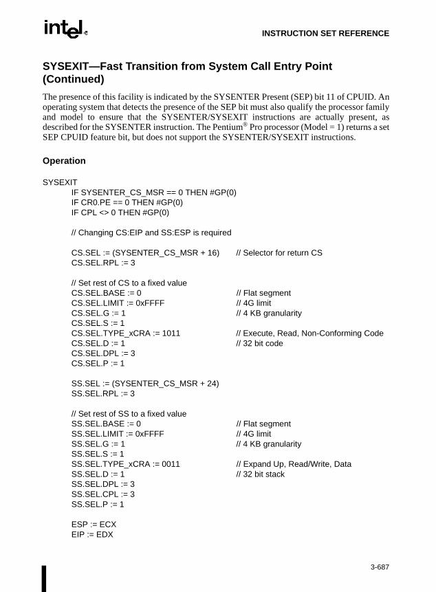
INSTRUCTION SET REFERENCE
SYSEXIT—Fast Transition from System Call Entry Point (Continued)
The presence of this facility is indicated by the SYSENTER Present (SEP) bit 11 of CPUID. Anoperating system that detects the presence of the SEP bit must also qualify the processor familyand model to ensure that the SYSENTER/SYSEXIT instructions are actually present, asdescribed for the SYSENTER instruction. The Pentium® Pro processor (Model = 1) returns a setSEP CPUID feature bit, but does not support the SYSENTER/SYSEXIT instructions.
Operation
SYSEXITIF SYSENTER_CS_MSR == 0 THEN #GP(0)IF CR0.PE == 0 THEN #GP(0)IF CPL <> 0 THEN #GP(0)
// Changing CS:EIP and SS:ESP is required
CS.SEL := (SYSENTER_CS_MSR + 16) // Selector for return CSCS.SEL.RPL := 3
// Set rest of CS to a fixed valueCS.SEL.BASE := 0 // Flat segmentCS.SEL.LIMIT := 0xFFFF // 4G limitCS.SEL.G := 1 // 4 KB granularityCS.SEL.S := 1CS.SEL.TYPE_xCRA := 1011 // Execute, Read, Non-Conforming CodeCS.SEL.D := 1 // 32 bit codeCS.SEL.DPL := 3CS.SEL.P := 1
SS.SEL := (SYSENTER_CS_MSR + 24)SS.SEL.RPL := 3
// Set rest of SS to a fixed valueSS.SEL.BASE := 0 // Flat segmentSS.SEL.LIMIT := 0xFFFF // 4G limitSS.SEL.G := 1 // 4 KB granularitySS.SEL.S := 1SS.SEL.TYPE_xCRA := 0011 // Expand Up, Read/Write, DataSS.SEL.D := 1 // 32 bit stackSS.SEL.DPL := 3SS.SEL.CPL := 3SS.SEL.P := 1
ESP := ECXEIP := EDX
3-687

INSTRUCTION SET REFERENCE
SYSEXIT—Fast Transition from System Call Entry Point (Continued)
Exceptions
#GP(0) If SYSENTER_CS_MSR contains zero.
Numeric Exceptions
None.
Protected Mode Exceptions
#GP(0) If CPL is non-zero.
Real Address Mode Exceptions
#GP(0) If protected mode is not enabled.
3-688

INSTRUCTION SET REFERENCE
TEST—Logical Compare
Description
This instruction computes the bit-wise logical AND of first operand (source 1 operand) and thesecond operand (source 2 operand) and sets the SF, ZF, and PF status flags according to theresult. The result is then discarded.
Operation
TEMP ← SRC1 AND SRC2;SF ← MSB(TEMP);IF TEMP = 0
THEN ZF ← 1;ELSE ZF ← 0;
FI:PF ← BitwiseXNOR(TEMP[0:7]);CF ← 0;OF ← 0;(*AF is Undefined*)
Flags Affected
The OF and CF flags are cleared to 0. The SF, ZF, and PF flags are set according to the result(refer to the “Operation” section above). The state of the AF flag is undefined.
Opcode Instruction Description
A8 ib TEST AL,imm8 AND imm8 with AL; set SF, ZF, PF according to result
A9 iw TEST AX,imm16 AND imm16 with AX; set SF, ZF, PF according to result
A9 id TEST EAX,imm32 AND imm32 with EAX; set SF, ZF, PF according to result
F6 /0 ib TEST r/m8,imm8 AND imm8 with r/m8; set SF, ZF, PF according to result
F7 /0 iw TEST r/m16,imm16 AND imm16 with r/m16; set SF, ZF, PF according to result
F7 /0 id TEST r/m32,imm32 AND imm32 with r/m32; set SF, ZF, PF according to result
84 /r TEST r/m8,r8 AND r8 with r/m8; set SF, ZF, PF according to result
85 /r TEST r/m16,r16 AND r16 with r/m16; set SF, ZF, PF according to result
85 /r TEST r/m32,r32 AND r32 with r/m32; set SF, ZF, PF according to result
3-689

INSTRUCTION SET REFERENCE
TEST—Logical Compare (Continued)
Protected Mode Exceptions
#GP(0) If a memory operand effective address is outside the CS, DS, ES, FS, orGS segment limit.
If the DS, ES, FS, or GS register contains a null segment selector.
#SS(0) If a memory operand effective address is outside the SS segment limit.
#PF(fault-code) If a page fault occurs.
#AC(0) If alignment checking is enabled and an unaligned memory reference ismade while the current privilege level is 3.
Real-Address Mode Exceptions
#GP If a memory operand effective address is outside the CS, DS, ES, FS, orGS segment limit.
#SS If a memory operand effective address is outside the SS segment limit.
Virtual-8086 Mode Exceptions
#GP(0) If a memory operand effective address is outside the CS, DS, ES, FS, orGS segment limit.
#SS(0) If a memory operand effective address is outside the SS segment limit.
#PF(fault-code) If a page fault occurs.
#AC(0) If alignment checking is enabled and an unaligned memory reference ismade.
3-690
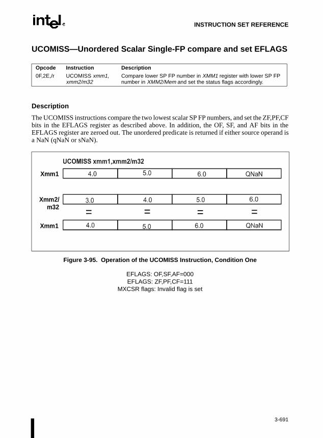
INSTRUCTION SET REFERENCE
UCOMISS—Unordered Scalar Single-FP compare and set EFLAGS
Description
The UCOMISS instructions compare the two lowest scalar SP FP numbers, and set the ZF,PF,CFbits in the EFLAGS register as described above. In addition, the OF, SF, and AF bits in theEFLAGS register are zeroed out. The unordered predicate is returned if either source operand isa NaN (qNaN or sNaN).
Figure 3-95. Operation of the UCOMISS Instruction, Condition One
EFLAGS: OF,SF,AF=000EFLAGS: ZF,PF,CF=111
MXCSR flags: Invalid flag is set
Opcode Instruction Description
0F,2E,/r UCOMISS xmm1, xmm2/m32
Compare lower SP FP number in XMM1 register with lower SP FP number in XMM2/Mem and set the status flags accordingly.
Xmm1
Xmm2/m32
Xmm1
= = = =
3-691

INSTRUCTION SET REFERENCE
UCOMISS—Unordered Scalar Single-FP compare and set EFLAGS (Continued)
Figure 3-96. Operation of the UCOMISS Instruction, Condition Two
EFLAGS: OF,SF,AF=000EFLAGS: ZF,PF,CF=000
MXCSR flags: Invalid flag is set
Figure 3-97. Operation of the UCOMISS Instruction, Condition Three
EFLAGS: OF,SF,AF=000EFLAGS: ZF,PF,CF=001
MXCSR flags: Invalid flag is set
Xmm1
Xmm2/m32
Xmm1
= = = =
Xmm1
Xmm2/m32
Xmm1
= = = =
3-692
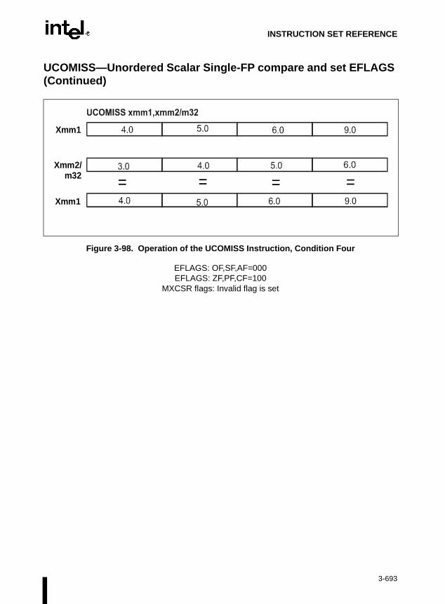
INSTRUCTION SET REFERENCE
UCOMISS—Unordered Scalar Single-FP compare and set EFLAGS (Continued)
Figure 3-98. Operation of the UCOMISS Instruction, Condition Four
EFLAGS: OF,SF,AF=000EFLAGS: ZF,PF,CF=100
MXCSR flags: Invalid flag is set
Xmm1
Xmm2/m32
Xmm1
= = = =
3-693

INSTRUCTION SET REFERENCE
UCOMISS—Unordered Scalar Single-FP compare and set EFLAGS (Continued)
Operation
OF = 0;SF = 0;AF = 0;
IF ((DEST[31-0] UNORD SRC/m32[31-0]) = TRUE) THENZF = 1;PF = 1;CF = 1;
ELSEIF ((DEST[31-0] GTRTHAN SRC/m32[31-0]) = TRUE)THEN
ZF = 0;PF = 0;CF = 0;
ELSEIF ((DEST[31-0] LESSTHAN SRC/m32[31-0]) = TRUE THEN
ZF = 0;PF = 0;CF = 1;
ELSEZF = 1;PF = 0;CF = 0;
FIFI
FI
3-694

INSTRUCTION SET REFERENCE
UCOMISS—Unordered Scalar Single-FP compare and set EFLAGS (Continued)
Intel C/C++ Compiler Intrinsic Equivalent
_mm_ucomieq_ss(__m128 a, __m128 b)
Compares the lower SP FP value of a and b for a equal to b. If a and b are equal, 1 is returned.Otherwise 0 is returned.
_mm_ucomilt_ss(__m128 a, __m128 b)
Compares the lower SP FP value of a and b for a less than b. If a is less than b, 1 is returned.Otherwise 0 is returned.
_mm_ucomile_ss(__m128 a, __m128 b)
Compares the lower SP FP value of a and b for a less than or equal to b. If a is less than or equalto b, 1 is returned. Otherwise 0 is returned.
_mm_ucomigt_ss(__m128 a, __m128 b)
Compares the lower SP FP value of a and b for a greater than b. If a is greater than b are equal,1 is returned. Otherwise 0 is returned.
_mm_ucomige_ss(__m128 a, __m128 b)
Compares the lower SP FP value of a and b for a greater than or equal to b. If a is greater thanor equal to b, 1 is returned. Otherwise 0 is returned.
_mm_ucomineq_ss(__m128 a, __m128 b)
Compares the lower SP FP value of a and b for a not equal to b. If a and b are not equal, 1 isreturned. Otherwise 0 is returned.
Exceptions
None.
Numeric Exceptions
Invalid (if sNaN operands), Denormal. Integer EFLAGS values will not be updated in the pres-ence of unmasked numeric exceptions.
3-695

INSTRUCTION SET REFERENCE
UCOMISS—Unordered Scalar Single-FP compare and set EFLAGS (Continued)
Protected Mode Exceptions
#GP(0) For an illegal memory operand effective address in the CS, DS, ES, FS, orGS segments.
#SS(0) For an illegal address in the SS segment.
#PF (fault-code) For a page fault.
#UD If CR0.EM = 1.
#NM If TS bit in CR0 is set.
#AC For unaligned memory reference. To enable #AC exceptions, three condi-tions must be true(CR0.AM is set; EFLAGS.AC is set; current CPL is 3).
#XM For an unmasked Streaming SIMD Extension numeric exception(CR4.OSXMMEXCPT =1).
#UD For an unmasked Streaming SIMD Extension numeric exception(CR4.OSXMMEXCPT =0).
#UD If CR4.OSFXSR(bit 9) = 0.
#UD If CPUID.XMM(EDX bit 25) = 0.
Real Address Mode Exceptions
Interrupt 13 If any part of the operand would lie outside of the effective address spacefrom 0 to 0FFFFH.
#UD If CR0.EM = 1.
#NM If TS bit in CR0 is set.
#XM For an unmasked Streaming SIMD Extension numeric exception(CR4.OSXMMEXCPT =1).
#UD For an unmasked Streaming SIMD Extension numeric exception(CR4.OSXMMEXCPT =0).
#UD If CR4.OSFXSR(bit 9) = 0.
#UD If CPUID.XMM(EDX bit 25) = 0.
3-696

INSTRUCTION SET REFERENCE
UCOMISS—Unordered Scalar Single-FP compare and set EFLAGS (Continued)
Virtual 8086 Mode Exceptions
Same exceptions as in Real Address Mode.
#AC For unaligned memory reference if the current privilege level is 3.
#PF (fault-code) For a page fault.
Comments
UCOMISS differs from COMISS in that it signals an invalid numeric exception when a sourceoperand is an sNaN; COMISS signals invalid if a source operand is either a qNaN or an sNaN.
The usage of Repeat (F2H, F3H) and Operand-size (66H) prefixes with UCOMISS is reserved.Different processor implementations may handle these prefixes differently. Usage of theseprefixes with UCOMISS risks incompatibility with future processors.
3-697

INSTRUCTION SET REFERENCE
UD2—Undefined Instruction
Description
This instruction generates an invalid opcode. This instruction is provided for software testing toexplicitly generate an invalid opcode. The opcode for this instruction is reserved for thispurpose.
Other than raising the invalid opcode exception, this instruction is the same as the NOP instruc-tion.
Operation
#UD (* Generates invalid opcode exception *);
Flags Affected
None.
Exceptions (All Operating Modes)
#UD Instruction is guaranteed to raise an invalid opcode exception in all oper-ating modes).
Opcode Instruction Description
0F 0B UD2 Raise invalid opcode exception
3-698

INSTRUCTION SET REFERENCE
UNPCKHPS—Unpack High Packed Single-FP Data
Description
The UNPCKHPS instruction performs an interleaved unpack of the high-order data elements ofXMM1 and XMM2/Mem. It ignores the lower half of the sources.
Example 3-2. UNPCKHPS Instruction
Opcode Instruction Description
0F,15,/r UNPCKHPS xmm1, xmm2/m128
Interleaves SP FP numbers from the high halves of XMM1 and XMM2/Mem into XMM1 register.
X4 X3 X2 X1
Y4 Y3 Y2 Y1
Y4 X4 Y3 X3
xmm1
xmm2/m128
xmm1
3-699
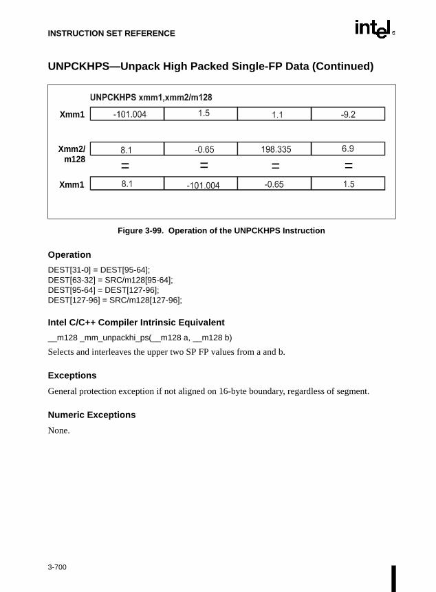
INSTRUCTION SET REFERENCE
UNPCKHPS—Unpack High Packed Single-FP Data (Continued)
Figure 3-99. Operation of the UNPCKHPS Instruction
Operation
DEST[31-0] = DEST[95-64];DEST[63-32] = SRC/m128[95-64];DEST[95-64] = DEST[127-96];DEST[127-96] = SRC/m128[127-96];
Intel C/C++ Compiler Intrinsic Equivalent
__m128 _mm_unpackhi_ps(__m128 a, __m128 b)
Selects and interleaves the upper two SP FP values from a and b.
Exceptions
General protection exception if not aligned on 16-byte boundary, regardless of segment.
Numeric Exceptions
None.
Xmm1
Xmm2/m128
Xmm1
= = = =
3-700

INSTRUCTION SET REFERENCE
UNPCKHPS—Unpack High Packed Single-FP Data (Continued)
Protected Mode Exceptions
#GP(0) For an illegal memory operand effective address in the CS, DS, ES, FS, orGS segments.
#SS(0) For an illegal address in the SS segment.
#PF(fault-code) For a page fault.
#UD If CR0.EM = 1.
#NM If TS bit in CR0 is set.
#UD If CR4.OSFXSR(bit 9) = 0.
#UD If CPUID.XMM(EDX bit 25) = 0.
Real Address Mode Exceptions
Interrupt 13 If any part of the operand would lie outside of the effective address spacefrom 0 to 0FFFFH.
#UD If CR0.EM = 1.
#NM If TS bit in CR0 is set.
#UD If CR4.OSFXSR(bit 9) = 0.
#UD If CPUID.XMM(EDX bit 25) = 0.
Virtual 8086 Mode Exceptions
Same exceptions as in Real Address Mode.
#PF(fault-code) For a page fault.
Comments
When unpacking from a memory operand, an implementation may decide to fetch only theappropriate 64 bits. Alignment to 16-byte boundary and normal segment checking will still beenforced.
The usage of Repeat Prefix (F3H) with UNPCKHPS is reserved. Different processor implemen-tations may handle this prefix differently. Usage of this prefix with UNPCKHPS risks incom-patibility with future processors.
3-701

INSTRUCTION SET REFERENCE
UNPCKLPS—Unpack Low Packed Single-FP Data
Description
The UNPCKLPS instruction performs an interleaved unpack of the low-order data elements ofXMM1 and XMM2/Mem. It ignores the upper half part of the sources.
Example 3-3. UNPCKLPS Instruction
Opcode Instruction Description
0F,14,/r UNPCKLPS xmm1, xmm2/m128
Interleaves SP FP numbers from the low halves of XMM1 and XMM2/Mem into XMM1 register.
X4 X3 X2 X1
Y4 Y3 Y2 Y1
Y2 X2 Y1 X1
xmm1
xmm2/m128
xmm1
3-702

INSTRUCTION SET REFERENCE
UNPCKLPS—Unpack Low Packed Single-FP Data (Continued)
Figure 3-100. Operation of the UNPCKLPS Instruction
Operation
DEST[31-0] = DEST[31-0];DEST[63-32] = SRC/m128[31-0];DEST[95-64] = DEST[63-32];DEST[127-96] = SRC/m128[63-32];
Intel C/C++ Compiler Intrinsic Equivalent
__m128 _mm_unpacklo_ps(__m128 a, __m128 b)
Selects and interleaves the lower two SP FP values from a and b.
Exceptions
General protection exception if not aligned on 16-byte boundary, regardless of segment.
Numeric Exceptions
None.
Xmm1
Xmm2/m128
Xmm1
= = = =
3-703

INSTRUCTION SET REFERENCE
UNPCKLPS—Unpack Low Packed Single-FP Data (Continued)
Protected Mode Exceptions
#GP(0) For an illegal memory operand effective address in the CS, DS, ES, FS, orGS segments.
#SS(0) For an illegal address in the SS segment.
#PF(fault-code) For a page fault.
#UD If CR0.EM = 1.
#NM If TS bit in CR0 is set.
#UD If CR4.OSFXSR(bit 9) = 0.
#UD If CPUID.XMM(EDX bit 25) = 0.
Real Address Mode Exceptions
Interrupt 13 If any part of the operand would lie outside of the effective address spacefrom 0 to 0FFFFH.
#UD If CR0.EM = 1.
#NM If TS bit in CR0 is set.
#UD If CR4.OSFXSR(bit 9) = 0.
#UD If CPUID.XMM(EDX bit 25) = 0.
Virtual 8086 Mode Exceptions
Same exceptions as in Real Address Mode.
#PF(fault-code) For a page fault.
Comments
When unpacking from a memory operand, an implementation may decide to fetch only theappropriate 64 bits. Alignment to 16-byte boundary and normal segment checking will still beenforced.
The usage of Repeat Prefixes (F2H, F3H) with UNPCKLPS is reserved. Different processorimplementations may handle this prefix differently. Usage of these prefixes with UNPCKLPSrisks incompatibility with future processors.
3-704

INSTRUCTION SET REFERENCE
er thanlector's
into theegmentcipate
VERR/VERW—Verify a Segment for Reading or Writing
Description
These instructions verify whether the code or data segment specified with the source operand isreadable (VERR) or writable (VERW) from the current privilege level (CPL). The sourceoperand is a 16-bit register or a memory location that contains the segment selector for thesegment to be verified. If the segment is accessible and readable (VERR) or writable (VERW),the ZF flag is set; otherwise, the ZF flag is cleared. Code segments are never verified as writable.This check cannot be performed on system segments.
To set the ZF flag, the following conditions must be met:
• The segment selector is not null.
• The selector must denote a descriptor within the bounds of the descriptor table (GDT orLDT).
• The selector must denote the descriptor of a code or data segment (not that of a systemsegment or gate).
• For the VERR instruction, the segment must be readable.
• For the VERW instruction, the segment must be a writable data segment.
• If the segment is not a conforming code segment, the segment’s DPL must be greator equal to (have less or the same privilege as) both the CPL and the segment seRPL.
The validation performed is the same as is performed when a segment selector is loaded DS, ES, FS, or GS register, and the indicated access (read or write) is performed. The sselector's value cannot result in a protection exception, enabling the software to antipossible segment access problems.
Opcode Instruction Description
0F 00 /4 VERR r/m16 Set ZF=1 if segment specified with r/m16 can be read
0F 00 /5 VERW r/m16 Set ZF=1 if segment specified with r/m16 can be written
3-705
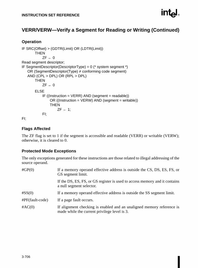
INSTRUCTION SET REFERENCE
VERR/VERW—Verify a Segment for Reading or Writing (Continued)
Operation
IF SRC(Offset) > (GDTR(Limit) OR (LDTR(Limit))THEN
ZF ← 0Read segment descriptor;IF SegmentDescriptor(DescriptorType) = 0 (* system segment *)
OR (SegmentDescriptor(Type) ≠ conforming code segment) AND (CPL > DPL) OR (RPL > DPL)
THENZF ← 0
ELSEIF ((Instruction = VERR) AND (segment = readable))
OR ((Instruction = VERW) AND (segment = writable))THEN
ZF ← 1;FI;
FI;
Flags Affected
The ZF flag is set to 1 if the segment is accessible and readable (VERR) or writable (VERW);otherwise, it is cleared to 0.
Protected Mode Exceptions
The only exceptions generated for these instructions are those related to illegal addressing of thesource operand.
#GP(0) If a memory operand effective address is outside the CS, DS, ES, FS, orGS segment limit.
If the DS, ES, FS, or GS register is used to access memory and it containsa null segment selector.
#SS(0) If a memory operand effective address is outside the SS segment limit.
#PF(fault-code) If a page fault occurs.
#AC(0) If alignment checking is enabled and an unaligned memory reference ismade while the current privilege level is 3.
3-706

INSTRUCTION SET REFERENCE
VERR/VERW—Verify a Segment for Reading or Writing (Continued)
Real-Address Mode Exceptions
#UD The VERR and VERW instructions are not recognized in real-addressmode.
Virtual-8086 Mode Exceptions
#UD The VERR and VERW instructions are not recognized in virtual-8086mode.
3-707

INSTRUCTION SET REFERENCE
WAIT/FWAIT—Wait
Description
These instructions cause the processor to check for and handle pending, unmasked, floating-point exceptions before proceeding. (FWAIT is an alternate mnemonic for the WAIT).
This instruction is useful for synchronizing exceptions in critical sections of code. Coding aWAIT instruction after a floating-point instruction insures that any unmasked floating-pointexceptions the instruction may raise are handled before the processor can modify the instruc-tion’s results. Refer to Section 7.9., Floating-Point Exception Synchronization in Chapter 7,Floating-Point Unit of the Intel Architecture Software Developer’s Manual, Volume 1, for moreinformation on using the WAIT/FWAIT instruction.
OperationCheckForPendingUnmaskedFloatingPointExceptions;
FPU Flags Affected
The C0, C1, C2, and C3 flags are undefined.
Floating-Point Exceptions
None.
Protected Mode Exceptions
#NM MP and TS in CR0 is set.
Real-Address Mode Exceptions
#NM MP and TS in CR0 is set.
Virtual-8086 Mode Exceptions
#NM MP and TS in CR0 is set.
Opcode Instruction Description
9B WAIT Check pending unmasked floating-point exceptions.
9B FWAIT Check pending unmasked floating-point exceptions.
3-708

INSTRUCTION SET REFERENCE
mainl-func-s cycle
pletes the
cteduction
WBINVD—Write Back and Invalidate Cache
Description
This instruction writes back all modified cache lines in the processor’s internal cache tomemory and invalidates (flushes) the internal caches. The instruction then issues a speciation bus cycle that directs external caches to also write back modified data and another buto indicate that the external caches should be invalidated.
After executing this instruction, the processor does not wait for the external caches to comtheir write-back and flushing operations before proceeding with instruction execution. It iresponsibility of hardware to respond to the cache write-back and flush signals.
The WDINVD instruction is a privileged instruction. When the processor is running in protemode, the CPL of a program or procedure must be 0 to execute this instruction. This instris also a serializing instruction. For more information, refer to Section 7.4., Serializing Instruc-tions in Chapter 7, Multiple-Processor Management of the Intel Architecture Software Devel-oper’s Manual, Volume 3.
In situations where cache coherency with main memory is not a concern, software can use theINVD instruction.
Intel Architecture Compatibility
The WBINVD instruction is implementation dependent, and its function may be implementeddifferently on future Intel Architecture processors. The instruction is not supported on IntelArchitecture processors earlier than the Intel486™ processor.
Operation
WriteBack(InternalCaches);Flush(InternalCaches);SignalWriteBack(ExternalCaches);SignalFlush(ExternalCaches);Continue (* Continue execution);
Flags Affected
None.
Protected Mode Exceptions
#GP(0) If the current privilege level is not 0.
Opcode Instruction Description
0F 09 WBINVD Write back and flush Internal caches; initiate writing-back and flushing of external caches.
3-709

INSTRUCTION SET REFERENCE
WBINVD—Write Back and Invalidate Cache (Continued)
Real-Address Mode Exceptions
None.
Virtual-8086 Mode Exceptions
#GP(0) The WBINVD instruction cannot be executed at the virtual-8086 mode.
3-710

INSTRUCTION SET REFERENCE
WRMSR—Write to Model Specific Register
Description
This instruction writes the contents of registers EDX:EAX into the 64-bit model specific register(MSR) specified in the ECX register. The high-order 32 bits are copied from EDX and the low-order 32 bits are copied from EAX. Always set the undefined or reserved bits in an MSR to thevalues previously read.
This instruction must be executed at privilege level 0 or in real-address mode; otherwise, ageneral protection exception #GP(0) will be generated. Specifying a reserved or unimplementedMSR address in ECX will also cause a general protection exception.
When the WRMSR instruction is used to write to an MTRR, the TLBs are invalidated, includingthe global entries. For more information, refer to Section 3.7., Translation Lookaside Buffers(TLBs) in Chapter 3, Protected-Mode Memory Management of the Intel Architecture SoftwareDeveloper’s Manual, Volume 3. MTRRs are an implementation-specific feature of the Pentium®
Pro processor.
The MSRs control functions for testability, execution tracing, performance monitoring andmachine check errors. Appendix B, Model-Specific Registers (MSRs), in the Intel ArchitectureSoftware Developer’s Manual, Volume 3, lists all the MSRs that can be written to with thisinstruction and their addresses.
The WRMSR instruction is a serializing instruction. For more information, refer to Section 7.4.,Serializing Instructions in Chapter 7, Multiple-Processor Management of the Intel ArchitectureSoftware Developer’s Manual, Volume 3.
The CPUID instruction should be used to determine whether MSRs are supported (EDX[5]=1)before using this instruction.
Intel Architecture Compatibility
The MSRs and the ability to read them with the WRMSR instruction were introduced into theIntel Architecture with the Pentium® processor. Execution of this instruction by an Intel Archi-tecture processor earlier than the Pentium® processor results in an invalid opcode exception#UD.
Operation
MSR[ECX] ← EDX:EAX;
Flags Affected
None.
Opcode Instruction Description
0F 30 WRMSR Write the value in EDX:EAX to MSR specified by ECX
3-711

INSTRUCTION SET REFERENCE
WRMSR—Write to Model Specific Register (Continued)
Protected Mode Exceptions
#GP(0) If the current privilege level is not 0.
If the value in ECX specifies a reserved or unimplemented MSR address.
Real-Address Mode Exceptions
#GP If the value in ECX specifies a reserved or unimplemented MSR address.
Virtual-8086 Mode Exceptions
#GP(0) The WRMSR instruction is not recognized in virtual-8086 mode.
3-712

INSTRUCTION SET REFERENCE
struc-ns on
ich is
S, or
it.
ce is
XADD—Exchange and Add
Description
This instruction exchanges the first operand (destination operand) with the second operand(source operand), then loads the sum of the two values into the destination operand. The desti-nation operand can be a register or a memory location; the source operand is a register.
This instruction can be used with a LOCK prefix.
Intel Architecture Compatibility
Intel Architecture processors earlier than the Intel486™ processor do not recognize this intion. If this instruction is used, you should provide an equivalent code sequence that ruearlier processors.
Operation
TEMP ← SRC + DESTSRC ← DESTDEST ← TEMP
Flags Affected
The CF, PF, AF, SF, ZF, and OF flags are set according to the result of the addition, whstored in the destination operand.
Protected Mode Exceptions
#GP(0) If the destination is located in a nonwritable segment.
If a memory operand effective address is outside the CS, DS, ES, FGS segment limit.
If the DS, ES, FS, or GS register contains a null segment selector.
#SS(0) If a memory operand effective address is outside the SS segment lim
#PF(fault-code) If a page fault occurs.
#AC(0) If alignment checking is enabled and an unaligned memory referenmade while the current privilege level is 3.
Opcode Instruction Description
0F C0/r XADD r/m8,r8 Exchange r8 and r/m8; load sum into r/m8.
0F C1/r XADD r/m16,r16 Exchange r16 and r/m16; load sum into r/m16.
0F C1/r XADD r/m32,r32 Exchange r32 and r/m32; load sum into r/m32.
3-713

INSTRUCTION SET REFERENCE
XADD—Exchange and Add (Continued)
Real-Address Mode Exceptions
#GP If a memory operand effective address is outside the CS, DS, ES, FS, orGS segment limit.
#SS If a memory operand effective address is outside the SS segment limit.
Virtual-8086 Mode Exceptions
#GP(0) If a memory operand effective address is outside the CS, DS, ES, FS, orGS segment limit.
#SS(0) If a memory operand effective address is outside the SS segment limit.
#PF(fault-code) If a page fault occurs.
#AC(0) If alignment checking is enabled and an unaligned memory reference ismade.
3-714

INSTRUCTION SET REFERENCE
ented LOCKore
ocess
XCHG—Exchange Register/Memory with Register
Description
This instruction exchanges the contents of the destination (first) and source (second) operands.The operands can be two general-purpose registers or a register and a memory location. If amemory operand is referenced, the processor’s locking protocol is automatically implemfor the duration of the exchange operation, regardless of the presence or absence of theprefix or of the value of the IOPL. Refer to the LOCK prefix description in this chapter for minformation on the locking protocol.
This instruction is useful for implementing semaphores or similar data structures for prsynchronization. Refer to Section 7.1.2., Bus Locking in Chapter 7, Multiple-ProcessorManagement of the Intel Architecture Software Developer’s Manual, Volume 3, for more infor-mation on bus locking.
The XCHG instruction can also be used instead of the BSWAP instruction for 16-bit operands.
Operation
TEMP ← DESTDEST ← SRCSRC ← TEMP
Flags Affected
None.
Opcode Instruction Description
90+rw XCHG AX,r16 Exchange r16 with AX
90+rw XCHG r16,AX Exchange AX with r16
90+rd XCHG EAX,r32 Exchange r32 with EAX
90+rd XCHG r32,EAX Exchange EAX with r32
86 /r XCHG r/m8,r8 Exchange r8 (byte register) with byte from r/m8
86 /r XCHG r8,r/m8 Exchange byte from r/m8 with r8 (byte register)
87 /r XCHG r/m16,r16 Exchange r16 with word from r/m16
87 /r XCHG r16,r/m16 Exchange word from r/m16 with r16
87 /r XCHG r/m32,r32 Exchange r32 with doubleword from r/m32
87 /r XCHG r32,r/m32 Exchange doubleword from r/m32 with r32
3-715

INSTRUCTION SET REFERENCE
XCHG—Exchange Register/Memory with Register (Continued)
Protected Mode Exceptions
#GP(0) If either operand is in a nonwritable segment.
If a memory operand effective address is outside the CS, DS, ES, FS, orGS segment limit.
If the DS, ES, FS, or GS register contains a null segment selector.
#SS(0) If a memory operand effective address is outside the SS segment limit.
#PF(fault-code) If a page fault occurs.
#AC(0) If alignment checking is enabled and an unaligned memory reference ismade while the current privilege level is 3.
Real-Address Mode Exceptions
#GP If a memory operand effective address is outside the CS, DS, ES, FS, orGS segment limit.
#SS If a memory operand effective address is outside the SS segment limit.
Virtual-8086 Mode Exceptions
#GP(0) If a memory operand effective address is outside the CS, DS, ES, FS, orGS segment limit.
#SS(0) If a memory operand effective address is outside the SS segment limit.
#PF(fault-code) If a page fault occurs.
#AC(0) If alignment checking is enabled and an unaligned memory reference ismade.
3-716

INSTRUCTION SET REFERENCE
nd”AT. Thisenta-ify the, which
lso.
S, or
it.
XLAT/XLATB—Table Look-up Translation
Description
This instruction locates a byte entry in a table in memory, using the contents of the AL registeras a table index, then copies the contents of the table entry back into the AL register. The indexin the AL register is treated as an unsigned integer. The XLAT and XLATB instructions get thebase address of the table in memory from either the DS:EBX or the DS:BX registers (dependingon the address-size attribute of the instruction, 32 or 16, respectively). The DS segment may beoverridden with a segment override prefix.
At the assembly-code level, two forms of this instruction are allowed: the “explicit-operaform and the “no-operand” form. The explicit-operand form (specified with the XLmnemonic) allows the base address of the table to be specified explicitly with a symbolexplicit-operands form is provided to allow documentation; however, note that the documtion provided by this form can be misleading. That is, the symbol does not have to speccorrect base address. The base address is always specified by the DS:(E)BX registersmust be loaded correctly before the XLAT instruction is executed.
The no-operands form (XLATB) provides a “short form” of the XLAT instructions. Here athe processor assumes that the DS:(E)BX registers contain the base address of the table
Operation
IF AddressSize = 16THEN
AL ← (DS:BX + ZeroExtend(AL))ELSE (* AddressSize = 32 *)
AL ← (DS:EBX + ZeroExtend(AL));FI;
Flags Affected
None.
Protected Mode Exceptions
#GP(0) If a memory operand effective address is outside the CS, DS, ES, FGS segment limit.
If the DS, ES, FS, or GS register contains a null segment selector.
#SS(0) If a memory operand effective address is outside the SS segment lim
#PF(fault-code) If a page fault occurs.
Opcode Instruction Description
D7 XLAT m8 Set AL to memory byte DS:[(E)BX + unsigned AL]
D7 XLATB Set AL to memory byte DS:[(E)BX + unsigned AL]
3-717

INSTRUCTION SET REFERENCE
XLAT/XLATB—Table Look-up Translation (Continued)
Real-Address Mode Exceptions
#GP If a memory operand effective address is outside the CS, DS, ES, FS, orGS segment limit.
#SS If a memory operand effective address is outside the SS segment limit.
Virtual-8086 Mode Exceptions
#GP(0) If a memory operand effective address is outside the CS, DS, ES, FS, orGS segment limit.
#SS(0) If a memory operand effective address is outside the SS segment limit.
#PF(fault-code) If a page fault occurs.
3-718

INSTRUCTION SET REFERENCE
XOR—Logical Exclusive OR
Description
This instruction performs a bitwise exclusive OR (XOR) operation on the destination (first) andsource (second) operands and stores the result in the destination operand location. The sourceoperand can be an immediate, a register, or a memory location; the destination operand can bea register or a memory location. (However, two memory operands cannot be used in one instruc-tion.) Each bit of the result is 1 if the corresponding bits of the operands are different; each bitis 0 if the corresponding bits are the same.
Operation
DEST ← DEST XOR SRC;
Flags Affected
The OF and CF flags are cleared; the SF, ZF, and PF flags are set according to the result. Thestate of the AF flag is undefined.
Opcode Instruction Description
34 ib XOR AL,imm8 AL XOR imm8
35 iw XOR AX,imm16 AX XOR imm16
35 id XOR EAX,imm32 EAX XOR imm32
80 /6 ib XOR r/m8,imm8 r/m8 XOR imm8
81 /6 iw XOR r/m16,imm16 r/m16 XOR imm16
81 /6 id XOR r/m32,imm32 r/m32 XOR imm32
83 /6 ib XOR r/m16,imm8 r/m16 XOR imm8 (sign-extended)
83 /6 ib XOR r/m32,imm8 r/m32 XOR imm8 (sign-extended)
30 /r XOR r/m8,r8 r/m8 XOR r8
31 /r XOR r/m16,r16 r/m16 XOR r16
31 /r XOR r/m32,r32 r/m32 XOR r32
32 /r XOR r8,r/m8 r8 XOR r/m8
33 /r XOR r16,r/m16 r8 XOR r/m8
33 /r XOR r32,r/m32 r8 XOR r/m8
3-719

INSTRUCTION SET REFERENCE
XOR—Logical Exclusive OR (Continued)
Protected Mode Exceptions
#GP(0) If the destination operand points to a nonwritable segment.
If a memory operand effective address is outside the CS, DS, ES, FS, orGS segment limit.
If the DS, ES, FS, or GS register contains a null segment selector.
#SS(0) If a memory operand effective address is outside the SS segment limit.
#PF(fault-code) If a page fault occurs.
#AC(0) If alignment checking is enabled and an unaligned memory reference ismade while the current privilege level is 3.
Real-Address Mode Exceptions
#GP If a memory operand effective address is outside the CS, DS, ES, FS, orGS segment limit.
#SS If a memory operand effective address is outside the SS segment limit.
Virtual-8086 Mode Exceptions
#GP(0) If a memory operand effective address is outside the CS, DS, ES, FS, orGS segment limit.
#SS(0) If a memory operand effective address is outside the SS segment limit.
#PF(fault-code) If a page fault occurs.
#AC(0) If alignment checking is enabled and an unaligned memory reference ismade.
3-720

INSTRUCTION SET REFERENCE
XORPS—Bit-wise Logical Xor for Single-FP Data
Description
The XORPS instruction returns a bit-wise logical XOR between XMM1 and XMM2/Mem.
Figure 3-101. Operation of the XORPS Instruction
Operation
DEST[127-0] = DEST/m128[127-0] XOR SRC/m128[127-0]
Intel C/C++ Compiler Intrinsic Equivalent
__m128 _mm_xor_ps(__m128 a, __m128 b)
Computes bitwise EXOR (exclusive-or) of the four SP FP values of a and b.
Exceptions
General protection exception if not aligned on 16-byte boundary, regardless of segment.
Opcode Instruction Description
0F,57,/r XORPS xmm1, xmm2/m128 XOR 128 bits from XMM2/Mem to XMM1 register.
< < <<Xmm1
Xmm2/m128
Xmm1
= = = =
3-721

INSTRUCTION SET REFERENCE
XORPS—Bit-wise Logical Xor for Single-FP Data (Continued)
Numeric Exceptions
None.
Protected Mode Exceptions
#GP(0) For an illegal memory operand effective address in the CS, DS, ES, FS, orGS segments.
#SS(0) For an illegal address in the SS segment.
#PF(fault-code) For a page fault.
#UD If CR0.EM = 1.
#NM If TS bit in CR0 is set.
#UD If CR4.OSFXSR(bit 9) = 0.
#UD If CPUID.XMM(EDX bit 25) = 0.
Real Address Mode Exceptions
Interrupt 13 If any part of the operand would lie outside of the effective address spacefrom 0 to 0FFFFH.
#UD If CR0.EM = 1.
#NM If TS bit in CR0 is set.
#UD If CR4.OSFXSR(bit 9) = 0.
#UD If CPUID.XMM(EDX bit 25) = 0.
Virtual 8086 Mode Exceptions
Same exceptions as in Real Address Mode.
#PF(fault-code) For a page fault.
Comments
The usage of Repeat Prefix (F3H) with XORPS is reserved. Different processor implementa-tions may handle this prefix differently. Usage of this prefix with XORPS risks incompatibility.
3-722

A
Opcode Map

s. Theroughgs areiven incode
APPENDIX AOPCODE MAP
The opcode tables in this chapter are provided to aid in interpreting Intel Architecture objectcode. The instructions are divided into three encoding groups: 1-byte opcode encodings, 2-byteopcode encodings, and escape (floating-point) encodings. The 1- and 2-byte opcode encodingsare used to encode integer, system, MMX™ technology, and Streaming SIMD Extensionopcode maps for these instructions are given in Tables A-1 through A-5. Sections A.3.1. thA.3.4. give instructions for interpreting 1- and 2-byte opcode maps. The escape encodinused to encode floating-point instructions. The opcode maps for these instructions are gTables A-6 through A-21. Section A.3.4. gives instructions for interpreting the escape opmaps.
The opcode tables in this section aid in interpreting Pentium® processor object code. Use thefour high-order bits of the opcode as an index to a row of the opcode table; use the four low-order bits as an index to a column of the table. If the opcode is 0FH, refer to the 2-byte opcodetable and use the second byte of the opcode to index the rows and columns of that table.
The escape (ESC) opcode tables for floating-point instructions identify the eight high-order bitsof the opcode at the top of each page. If the accompanying ModR/M byte is in the range 00Hthrough BFH, bits 3 through 5 identified along the top row of the third table on each page, alongwith the REG bits of the ModR/M, determine the opcode. ModR/M bytes outside the range 00Hthrough BFH are mapped by the bottom two tables on each page.
Refer to Chapter 2 for detailed information on the ModR/M byte, register values, and the variousaddressing forms.
A.1. KEY TO ABBREVIATIONS
Operands are identified by a two-character code of the form Zz. The first character, an uppercaseletter, specifies the addressing method; the second character, a lowercase letter, specifies thetype of operand.
A.2. CODES FOR ADDRESSING METHOD
The following abbreviations are used for addressing methods:
A Direct address. The instruction has no ModR/M byte; the address of the operand is en-coded in the instruction; and no base register, index register, or scaling factor can beapplied (for example, far JMP (EA)).
C The reg field of the ModR/M byte selects a control register (for example, MOV (0F20, 0F22)).
A-1

OPCODE MAP
reg-
ithere ad-e reg-
ple,
OV
OV
ithere ad-e reg-
, or
NS,
D The reg field of the ModR/M byte selects a debug register (for example, MOV (0F21,0F23)).
E A ModR/M byte follows the opcode and specifies the operand. The operand is either ageneral-purpose register or a memory address. If it is a memory address, the address iscomputed from a segment register and any of the following values: a base register, anindex register, a scaling factor, a displacement.
F EFLAGS Register.
G The reg field of the ModR/M byte selects a general register (for example, AX (000)).
I Immediate data. The operand value is encoded in subsequent bytes of the instruction.
J The instruction contains a relative offset to be added to the instruction pointer register(for example, JMP (0E9), LOOP).
M The ModR/M byte may refer only to memory (for example, BOUND, LES, LDS, LSS,LFS, LGS, CMPXCHG8B).
O The instruction has no ModR/M byte; the offset of the operand is coded as a word ordouble word (depending on address size attribute) in the instruction. No base register,index register, or scaling factor can be applied (for example, MOV (A0–A3)).
P The reg field of the ModR/M byte selects a packed quadword MMX™ technologyister.
Q A ModR/M byte follows the opcode and specifies the operand. The operand is ean MMX™ technology register or a memory address. If it is a memory address, thdress is computed from a segment register and any of the following values: a basister, an index register, a scaling factor, and a displacement.
R The mod field of the ModR/M byte may refer only to a general register (for examMOV (0F20-0F24, 0F26)).
S The reg field of the ModR/M byte selects a segment register (for example, M(8C,8E)).
T The reg field of the ModR/M byte selects a test register (for example, M(0F24,0F26)).
V The reg field of the ModR/M byte selects a packed SIMD floating-point register.
W An ModR/M byte follows the opcode and specifies the operand. The operand is ea SIMD floating-point register or a memory address. If it is a memory address, thdress is computed from a segment register and any of the following values: a basister, an index register, a scaling factor, and a displacement
X Memory addressed by the DS:SI register pair (for example, MOVS, CMPS, OUTSLODS).
Y Memory addressed by the ES:DI register pair (for example, MOVS, CMPS, ISTOS, or SCAS).
A-2

OPCODE MAP
by itsster isisters usedize at-
e used.
A.2.1. Codes for Operand Type
The following abbreviations are used for operand types:
a Two one-word operands in memory or two double-word operands in memory, depend-ing on operand-size attribute (used only by the BOUND instruction).
b Byte, regardless of operand-size attribute.
c Byte or word, depending on operand-size attribute.
d Doubleword, regardless of operand-size attribute.
dq Double-quadword, regardless of operand-size attribute.
p 32-bit or 48-bit pointer, depending on operand-size attribute.
pi Quadword MMX™ technology register (e.g. mm0)
ps 128-bit packed FP single-precision data.
q Quadword, regardless of operand-size attribute.
s 6-byte pseudo-descriptor.
ss Scalar element of a 128-bit packed FP single-precision data.
si Doubleword integer register (e.g., eax)
v Word or doubleword, depending on operand-size attribute.
w Word, regardless of operand-size attribute.
A.2.2. Register Codes
When an operand is a specific register encoded in the opcode, the register is identifiedname (for example, AX, CL, or ESI). The name of the register indicates whether the regi32, 16, or 8 bits wide. A register identifier of the form eXX is used when the width of the regdepends on the operand-size attribute. For example, eAX indicates that the AX register iwhen the operand-size attribute is 16, and the EAX register is used when the operand-stribute is 32.
A.3. OPCODE LOOK-UP EXAMPLES
This section provides several examples to demonstrate how the following opcode maps arRefer to the introduction to Chapter 3, Instruction Set Reference, in the Intel Architecture Soft-ware Developer’s Manual, Volume 2 for detailed information on the ModR/M byte, register val-ues, and the various addressing forms.
A-3

OPCODE MAP
hat theection
A.3.1. One-Byte Opcode Instructions
The opcode maps for 1-byte opcodes are shown in Tables A-1 and A-2. Looking at the 1-byteopcode maps, the instruction and its operands can be determined from the hexadecimal opcode.For example:
Opcode: 030500000000H
Opcode 030500000000H for an ADD instruction can be interpreted from the 1-byte opcode mapas follows. The first digit (0) of the opcode indicates the row, and the second digit (3) indicatesthe column in the opcode map tables. The first operand (type Gv) indicates a general registerthat is a word or doubleword depending on the operand-size attribute. The second operand (typeEv) indicates that a ModR/M byte follows that specifies whether the operand is a word or dou-bleword general-purpose register or a memory address. The ModR/M byte for this instruction is05H, which indicates that a 32-bit displacement follows (00000000H). The reg/opcode portionof the ModR/M byte (bits 3 through 5) is 000, indicating the EAX register. Thus, it can be de-termined that the instruction for this opcode is ADD EAX, mem_op, and the offset of mem_opis 00000000H.
Some 1- and 2-byte opcodes point to “group” numbers. These group numbers indicate tinstruction uses the reg/opcode bits in the ModR/M byte as an opcode extension (refer to SA.3.3.).
LSB address MSB address
03 05 00 00 00 00
A-4

OPCODE MAP
tech-
A-5
A.3.2. Two-Byte Opcode Instructions
Instructions that begin with 0FH can be found in the two-byte opcode maps given in Tables A-3 and A-4. The second opcode byte is used to reference a particular row and column in the tables.For example, the opcode 0FA4050000000003H is located on the two-byte opcode map in rowA, column 4. This opcode indicates a SHLD instruction with the operands Ev, Gv, and Ib. Theseoperands are defined as follows:
Ev The ModR/M byte follows the opcode to specify a word or doubleword operand
Gv The reg field of the ModR/M byte selects a general-purpose register
Ib Immediate data is encoded in the subsequent byte of the instruction.
The third byte is the ModR/M byte (05H). The mod and opcode/reg fields indicate that a 32-bitdisplacement follows, located in the EAX register, and is the source.
The next part of the opcode is the 32-bit displacement for the destination memory operand(00000000H), and finally the immediate byte representing the count of the shift (03H).
By this breakdown, it has been shown that this opcode represents the instruction:
SHLD DS:00000000H, EAX, 3
The next part of the SHLD opcode is the 32-bit displacement for the destination memory oper-and (00000000H), which is followed by the immediate byte representing the count of the shift(03H). By this breakdown, it has been shown that the opcode 0FA4050000000003H representsthe instruction:
SHLD DS:00000000H, EAX, 3.
Lower case is used in the following tables to highlight the mnemonics added by MMX™ nology and Streaming SIMD Extensions.

OPCODE MAP
Table A-1. One-Byte Opcode Map1 (Left)
0 1 2 3 4 5 6 7
0 ADD PUSH
ESPOPES Eb, Gb Ev, Gv Gb, Eb Gv, Ev AL, Ib eAX, Iv
1 ADC PUSH
SS POPSS Eb, Gb Ev, Gv Gb, Eb Gv, Ev AL, Ib eAX, Iv
2 AND SEG
= ES DAA
Eb, Gb Ev, Gv Gb, Eb Gv, Ev AL, Ib eAX, Iv
3XOR SEG
= SS AAA
Eb, Gb Ev, Gv Gb, Eb Gb, Ev AL, Ib eAX, Iv
4 INC general register
eAX eCX eDX eBX eSP eBP eSI eDI
5 PUSH general register
eAX eCX eDX eBX eSP eBP eSI eDI
6 PUSHAPUSHAD
POPAPOPAD
BOUND Gv, Ma
ARPL Ew, Gw
SEG= FS
SEG= GS
Opd Size
Addr Size
7 Jcc - Short-displacement jump on condition
O NO B/NAE/C NB/AE/NC Z/E NZ/NE BE/NA NBE/A
8Immediate Grp 12 TEST XCHG
Eb, Ib Ev, Iv Ev, Ib Ev, Ib Eb, Gb Ev, Gv Eb, Gb Ev, Gv
9 NOP XCHG word or double-word register with eAX
eCX eDX eBX eSP eBP eSI eDI
AMOV MOVSB
Xb, Yb MOVSW
Xv, Yv CMPSBXb, Yb
CMPSWXv, YvAL, Ob eAX, Ov Ob, AL Ov, eAX
B MOV immediate byte into byte register
AL CL DL BL AH CH DH BH
CShift Grp 22 RET
IwRET LES
Gv, MpLDS
Gv, Mp Grp 122 - MOV
Eb,Ib Ev,Ib Eb, Ib Ev, Iv
DShift Grp 22 AAM
IbAAD
IbXLAT/XLATB
Eb, 1 Ev, 1 Eb, CL Ev, CL
E LOOPNELOOPNZ
Jb
LOOPE/LOOPZ
Jb
LOOPJb
JCXZ/JECXZ
Jb
IN OUT
AL, Ib eAX, Ib Ib, AL Ib, eAX
F LOCK REPNE REP/
REPE HLT CMC Unary Grp 32
Eb Ev
A-6

OPCODE MAP
A-7
Table A-2. One-Byte Opcode Map1 (Right)
NOTES:
1. All blanks in the opcode maps A-1 and A-2 are reserved and should not be used. Do not depend on theoperation of these undefined opcodes.
2. Bits 5, 4, and 3 of ModR/M byte used as an opcode extension (refer to Section A.3.3.).
8 9 A B C D E F
OR PUSHCS
2-byteescape 0
Eb, Gb Ev, Gv Gb, Eb Gv, Ev AL, Ib eAX, Iv POP CS
SBB PUSHDS
POPDS 1
Eb, Gb Ev, Gv Gb, Eb Gv, Ev AL, Ib eAX, Iv
SUB SEG=CS
DAS 2
Eb, Gb Ev, Gv Gb, Eb Gv, Ev AL, Ib eAX, Iv
CMP SEG=DS
AAS 3
Eb, Gb Ev, Gv Gb, Eb Gv, Ev AL, Ib eAX, Iv
DEC general register4
eAX eCX eDX eBX eSP eBP eSI eDI
POP into general register5
eAX eCX eDX eBX eSP eBP eSI eDI
PUSHIv
IMULGv, Ev, Iv
PUSHIb
IMULGv, Ev, Ib
INSBYb, DX
INSW/DYv, DX
OUTSBDX, Xb
OUTSW/DDX, Xv 6
Jcc - Short displacement jump on condition7
S NS P/PE NP/PO L/NGE NL/GE LE/NG NLE/G
MOV MOVEw, Sw
LEAGv, M
MOVSw, Ew
POPEv 8
Eb, Gb Ev, Gv Gb, Eb Gv, Ev
CBW/CWDE
CWD/CDQ
CALLAp
FWAIT/WAIT
PUSHF/PUSHFD
Fv
POPF/POPFD
Fv
SAHF LAHF 9
TEST STOS/STOSB Yb, AL
STOS/STOSW/STOTSDYv, eAX
LODSBAL, Xb
LODSW/LODSDeAX, Xv
SCAS/SCASBAL, Yb
SCASW/SCASD/SCAS
eAX, Xv
AAL, Ib eAX, Iv
MOV immediate word or double into word or double register B
eAX eCX eDX eBX eSP eBP eSI eDI
ENTERIw, Ib
LEAVE RETIw
RET INT3
INTIb
INTO IRET C
ESC (Escape to coprocessor instruction set) D
CALL Jv
JMP IN OUT E near
JVfarAP
shortJb
AL, DX eAX, DX DX, AL DX, eAX
CLC STC CLI STI CLD STD INC/DECGrp 42
INC/DECGrp 52 F

OPCODE MAP
Table A-3. Two-Byte Opcode Map1 (Left) (First Byte is OFH)
0 1 2 3 4 5 6 7
0 Grp 62 Grp 72 LARGv, Ew
LSLGv, Ew
CLTS
1
movupsVps, Wps
movss (F3)Vss, Wss
movupsWps, Vps
movss (F3)Wss, Vss
movlpsVq, Wqmovhlps Vq, Vq
movlpsVq, Wq
unpcklpsVps, Wq
unpckhpsVps, Wq
movhpsVq, Wqmovlhps Vq, Vq
movhpsWq, Vq
2 MOVRd, Cd
MOVRd, Dd
MOVCd, Rd
MOV Dd, Rd
3 WRMSR RDTSC RDMSR RDPMC SYSENTER SYSEXIT
4
CMOVcc - Conditional Move
O NO B/C/NAE AE/NB/NC E/Z NE/NZ BE/NA A/NBE
Gv, Ev
5
movmskpsEd, Vps
sqrtpsVps, Wpssqrtss (F3)Vss, Wss
rsqrtpsVps, Wps
rsqrtssVss, Wss
rcppsVps, Wps
rcpssVss, Wss
andpsVps, Wps
andnpsVps, Wps
orpsVps, Wps
xorpsVps, Wps
6 punpcklbwPq, Qd
punpcklwdPq, Qd
punpckldqPq, Qd
packsswbPq, Qq
pcmpgtbPq, Qq
pcmpgtwPq, Qq
pcmpgtdPq, Qq
packuswbPq, Qq
7pshimw3
Pq, Qq(Grp 132)
pshimd3
Pq, Qq(Grp 142)
pshimq3
Pq, Qq(Grp 152)
pcmpeqbPq, Qq
pcmpeqwPq, Qq
pcmpeqdPq, Qq
emms
8Jcc - Long-displacement jump on condition
O NO B/C/NAE AE/NB/NC E/Z NE/NZ BE/NA A/NBE
9
SETcc - Byte Set on condition (Eb)
O NO B/C/NAE AE/NB/NC E/Z NE/NZ BE/NA A/NBE
Eb
A PUSHFS
POPFS
CPUID BTEv, Gv
SHLDEv, Gv, Ib
SHLDEv, Gv, CL
BCMPXCHG, LSS
Mp BTR
Ev, Gv LFSMp
LGSMp
MOVZx
Eb, Gb Ev, Gv Gv, Eb Gv, Ew
C
XADDEb, Gb
XADDEv, Gv
cmppsVps, Wps, Ibcmpss (F3)
Vss, Wss, Ib
pinsrwPq, Ed, Ib
pextrwGd, Pq, Ib
shufpsVps, Wps, Ib
Grp 92
Dpsrlw
Pq, Qqpsrld
Pq, Qqpsrlq
Pq, QqpmullwPq, Qq
pmovmskbGd, Pq
EpavgbPq, Qq
psrawPq, Qq
psradPq, Qq
pavgwPq, Qq
pmulhuwPq, Qq
pmulhwPq, Qq
movntqWq, Vq
F psllwPq, Qq
pslldPq, Qq
psllqPq, Qq
pmaddwdPq, Qq
psadbwPq, Qq
A-8

OPCODE MAP
Table A-4. Two-Byte Opcode Map1 (Right) (First Byte is OFH)
NOTES:
1. All blanks in the opcode maps A-3 and A-4 are reserved and should not be used. Do not depend on theoperation of these undefined opcodes.
2. Bits 5, 4, and 3 of ModR/M byte used as an opcode extension (refer to Section A.3.3.).
3. These abbreviations are not actual mnemonics. When shifting by immediate shift counts, the PSHIMDmnemonic represents the PSLLD, PSRAD, and PSRLD instructions, PSHIMW represents the PSLLW,PSRAW, and PSRLW instructions, and PSHIMQ represents the PSLLQ and PSRLQ instructions. Theinstructions that shift by immediate counts are differentiated by ModR/M bytes (refer to Section A.3.3.).
4. Use the 0F0B opcode (UD2 instruction) or the 0FB9H opcode when deliberately trying to generate aninvalid opcode exception (#UD).
8 9 A B C D E F
INVD WBINVD2 byte Illegal
OpcodesUD24
0
Prefetch(Grp 172) 1
movapsVps, Wps
movapsWps, Vps
cvtpi2psVps, Qqcvtsi2ss
(F3)Vss, Qq
movntpsWps, Vps
cvttps2piQq, Wpscvttss2si
(F3)Gd, Wss
cvtps2piQq, Wpscvtss2si
(F3)Gd, Wss
ucomissVss, Wss
comissVps, Wps
2
3
CMOVcc - Conditional Move
4 S NS P/PE NP/PO L/NGE GE/NL LE/NG G/NLE
Gv, Ev
addpsVps, Wpsaddss (F3)Vss, Wss
mulpsVps, Wpsmulss (F3)Vss, Wss
subpsVps, Wpssubss (F3)Vss, Wss
minpsVps, Wpsminss (F3)Vss, Wss
divpsVps, Wpsdivss (F3)Vss, Wss
maxpsVps, Wps
maxss (F3)Vss, Wss
5
punpckhbwPq, Qd
punpckhwdPq, Qd
punpckhdqPq, Qd
packssdwPq, Qd
movdPd, Ed
movqPq, Qq 6
MMX UD movdEd, Pd
movqQq, Pq 7
Jcc - Long-displacement jump on condition8
S NS P/PE NP/PO L/NGE GE/NL LE/NG G/NLE
SETcc - Byte Set on condition
9 S NS P/PE NP/PO L/NGE GE/NL LE/NG G/NLE
Eb
PUSHGS
POPGS
RSM BTSEv, Gv
SHRDEv, Gv, Ib
SHRDEv, Gv, CL
Grp 162 IMULGv, Ev A
Grp 112
Invalid Opcode4
Grp 82
Ev, Ib BTC
Ev, Gv BSF
Gv, Ev BSR
Gv, Ev MOVSx
B Gv, Eb Gv, Ew
BSWAPC
EAX ECX EDX EBX ESP EBP ESI EDI
psubusbPq, Qq
psubuswPq, Qq
pminubPq, Qq
pandPq, Qq
paddusbPq, Qq
padduswPq, Qq
pmaxubPq, Qq
pandnPq, Qq D
psubsbPq, Qq
psubswPq, Qq
pminswPq, Qq
porPq, Qq
paddsbPq, Qq
paddswPq, Qq
pmaxswPq, Qq
pxorPq, Qq E
psubbPq, Qq
psubwPq, Qq
psubdPq, Qq
paddbPq, Qq
paddwPq, Qq
paddPq, Qq
F
A-9

OPCODE MAP
A.3.3. Opcode Extensions For One- And Two-byte Opcodes
Some of the 1-byte and 2-byte opcodes use bits 5, 4, and 3 of the ModR/M byte (the nnn fieldin Figure A-1) as an extension of the opcode. Those opcodes that have opcode extensions areindicated in Table A-5 with group numbers (Group 1, Group 2, etc.). The group numbers (rang-ing from 1 to A) provide an entry point into Table A-5 where the encoding of the opcode exten-sion field can be found. For example, the ADD instruction with a 1-byte opcode of 80H is aGroup 1 instruction. Table A-5 indicates that the opcode extension that must be encoded in theModR/M byte for this instruction is 000B.
mod nnn R/M
Figure A-1. ModR/M Byte nnn Field (Bits 5, 4, and 3)
A-10

OPCODE MAP
NOTE:
1. All blanks in the opcode map are reserved and should not be used. Do not depend on the operation ofthese undefined opcodes.
Table A-5. Opcode Extensions for One- and Two-Byte Opcodes by Group Number1
Encoding of Bits 5,4,3 of the ModR/M Byte
Opcode Group Mod 7,6
000 001 010 011 100 101 110 111
80-83 1 mem11
ADD OR ADC SBB AND SUB XOR CMP
C0, C1 reg, immD0, D1 reg, 1
D2, D3 reg, CL2 mem
11
ROL ROR RCL RCR SHL/SAL SHR SAR
F6, F7 3 mem11
TESTIb/Iv
NOT NEG MULAL/eAX
IMULAL/eAX
DIVAL/eAX
IDIVAL/eAX
FE 4 mem11
INCEb
DECEb
FF 5 mem11
INCEv
DECEv
CALLEv
CALLEp
JMPEv
JMPEp
PUSHEv
OF OO 6 mem11
SLDTEw
STREw
LLDTEw
LTREw
VERREw
VERWEw
OF O1 7 mem11
SGDTMs
SIDTMs
LGDTMs
LIDTMs
SMSWEw
LMSWEw
INVLPG
OF BA 8 mem11
BT BTS BTR BTC
OF C7 9mem CMPXCH8B
Mq
11
OF B9 11mem
11
C6
12
mem MOVEv, Iv
C7 11 MOVEv, Iv
OF 71 13
mem
11 psrlwPq, Ib
psrawPq, Ib
psllwPq, Ib
OF 72 14
mem
11 psrldPq, Ib
psradPq, Ib
pslldPq, Ib
OF 73 15
mem
11 psrlqPq, Ib
psllqPq, Ib
OF AE 16mem fxsave fxrstor ldmxcsr stmxcsr
11 sfence
OF 18 17mem prefetch
NTAprefetch
T0prefetch
T1prefetch
T2
11
A-11

OPCODE MAP
A.3.4. Escape Opcode Instructions
The opcode maps for the escape instruction opcodes (floating-point instruction opcodes) aregiven in Tables A-6 through A-21. These opcode maps are grouped by the first byte of the op-code from D8 through DF. Each of these opcodes has a ModR/M byte. If the ModR/M byte iswithin the range of 00H through BFH, bits 5, 4, and 3 of the ModR/M byte are used as an opcodeextension, similar to the technique used for 1-and 2-byte opcodes (refer to Section A.3.3.). If theModR/M byte is outside the range of 00H through BFH, the entire ModR/M byte is used as anopcode extension.
A.3.4.1. OPCODES WITH MODR/M BYTES IN THE 00H THROUGH BFH RANGE
The opcode DD0504000000H can be interpreted as follows. The instruction encoded with thisopcode can be located in Section A.3.4.8.. Since the ModR/M byte (05H) is within the 00Hthrough BFH range, bits 3 through 5 (000) of this byte indicate the opcode to be for an FLD dou-ble-real instruction (refer to Table A-8). The double-real value to be loaded is at 00000004H,which is the 32-bit displacement that follows and belongs to this opcode.
A.3.4.2. OPCODES WITH MODR/M BYTES OUTSIDE THE 00H THROUGH BFH RANGE
The opcode D8C1H illustrates an opcode with a ModR/M byte outside the range of 00H throughBFH. The instruction encoded here, can be located in Section A.3.4.. In Table A-7, the ModR/Mbyte C1H indicates row C, column 1, which is an FADD instruction using ST(0), ST(1) as theoperands.
A.3.4.3. ESCAPE OPCODES WITH D8 AS FIRST BYTE
Tables A-6 and A-7 contain the opcodes maps for the escape instruction opcodes that begin withD8H. Table A-6 shows the opcode map if the accompanying ModR/M byte within the range of00H through BFH. Here, the value of bits 5, 4, and 3 (the nnn field in Figure A-1) selects theinstruction.
Table A-6. D8 Opcode Map When ModR/M Byte is Within 00H to BFH1
nnn Field of ModR/M Byte (refer to Figure A-1)
000 001 010 011 100 101 110 111
FADD single-real
FMUL single-real
FCOM single-real
FCOMP single-real
FSUB single-real
FSUBR single-real
FDIV single-real
FDIVR single-real
A-12

OPCODE MAP
Table A-7 shows the opcode map if the accompanying ModR/M byte is outside the range of 00Hto BFH. In this case the first digit of the ModR/M byte selects the row in the table and the seconddigit selects the column.
Table A-7. D8 Opcode Map When ModR/M Byte is Outside 00H to BFH1
0 1 2 3 4 5 6 7
C FADD
ST(0),ST(0) ST(0),ST(1) ST(0),ST(2) ST(0),ST(3) ST(0),ST(4) ST(0),ST(5) ST(0),ST(6) ST(0),ST(7)
D FCOM
ST(0),ST(0) ST(0),ST(1) ST(0),T(2) ST(0),ST(3) ST(0),ST(4) ST(0),ST(5) ST(0),ST(6) ST(0),ST(7)
E FSUB
ST(0),ST(0) ST(0),ST(1) ST(0),ST(2) ST(0),ST(3) ST(0),ST(4) ST(0),ST(5) ST(0),ST(6) ST(0),ST(7)
F FDIV
ST(0),ST(0) ST(0),ST(1) ST(0),ST(2) ST(0),ST(3) ST(0),ST(4) ST(0),ST(5) ST(0),ST(6) ST(0),ST(7)
8 9 A B C D E F
C FMUL
ST(0),ST(0) ST(0),ST(1) ST(0),ST(2) ST(0),ST(3) ST(0),ST(4) ST(0),ST(5) ST(0),ST(6) ST(0),ST(7)
D FCOMP
ST(0),ST(0) ST(0),ST(1) ST(0),T(2) ST(0),ST(3) ST(0),ST(4) ST(0),ST(5) ST(0),ST(6) ST(0),ST(7)
E FSUBR
ST(0),ST(0) ST(0),ST(1) ST(0),ST(2) ST(0),ST(3) ST(0),ST(4) ST(0),ST(5) ST(0),ST(6) ST(0),ST(7)
F FDIVR
ST(0),ST(0) ST(0),ST(1) ST(0),ST(2) ST(0),ST(3) ST(0),ST(4) ST(0),ST(5) ST(0),ST(6) ST(0),ST(7)
A-13

OPCODE MAP
A.3.4.4. ESCAPE OPCODES WITH D9 AS FIRST BYTE
Tables A-8 and A-9 contain opcodes maps for escape instruction opcodes that begin with D9H.Table A-8 shows the opcode map if the accompanying ModR/M byte is within the range of 00Hthrough BFH. Here, the value of bits 5, 4, and 3 (the Figure A-1 nnn field) selects the instruction.
Table A-8. D9 Opcode Map When ModR/M Byte is Within 00H to BFH1.
NOTE:
1. All blanks in the opcode map are reserved and should not be used. Do not depend on the operation ofthese undefined opcodes.
Table A-9 shows the opcode map if the accompanying ModR/M byte is outside the range of 00Hto BFH. In this case the first digit of the ModR/M byte selects the row in the table and the seconddigit selects the column.
nnn Field of ModR/M Byte (refer to Figure A-1)
000 001 010 011 100 101 110 111
FLDsingle-real
FSTsingle-real
FSTPsingle-real
FLDENV14/28 bytes
FLDCW2 bytes
FSTENV14/28 bytes
FSTCW2 bytes
A-14

OPCODE MAP
Table A-9. D9 Opcode Map When ModR/M Byte is Outside 00H to BFH1
NOTE:
1. All blanks in the opcode map are reserved and should not be used. Do not depend on the operation ofthese undefined opcodes.
A.3.4.5. ESCAPE OPCODES WITH DA AS FIRST BYTE
Tables A-10 and A-11 contain the opcodes maps for the escape instruction opcodes that beginwith DAH. Table A-10 shows the opcode map if the accompanying ModR/M byte within therange of 00H through BFH. Here, the value of bits 5, 4, and 3 (the nnn field in Figure A-1) se-lects the instruction.
Table A-10. DA Opcode Map When ModR/M Byte is Within 00H to BFH1
NOTE:
1. All blanks in the opcode map are reserved and should not be used. Do not depend on the operation ofthese undefined opcodes.
0 1 2 3 4 5 6 7
C FLD
ST(0),ST(0) ST(0),ST(1) ST(0),ST(2) ST(0),ST(3) ST(0),ST(4) ST(0),ST(5) ST(0),ST(6) ST(0),ST(7)
D FNOP
E FCHS FABS FTST FXAM
F F2XM1 FYL2X FPTAN FPATAN FXTRACT FPREM1 FDECSTP FINCSTP
8 9 A B C D E F
C FXCH
ST(0),ST(0) ST(0),ST(1) ST(0),ST(2) ST(0),ST(3) ST(0),ST(4) ST(0),ST(5) ST(0),ST(6) ST(0),ST(7)
D
E FLD1 FLDL2T FLDL2E FLDPI FLDLG2 FLDLN2 FLDZ
F FPREM FYL2XP1 FSQRT FSINCOS FRNDINT FSCALE FSIN FCOS
nnn Field of ModR/M Byte (refer to Figure A-1)
000 001 010 011 100 101 110 111
FIADDdword-integer
FIMULdword-integer
FICOMdword-integer
FICOMPdword-integer
FISUBdword-integer
FISUBRdword-integer
FIDIVdword-integer
FIDIVRdword-integer
A-15

OPCODE MAP
Table A-11 shows the opcode map if the accompanying ModR/M byte is outside the range of00H to BFH. In this case the first digit of the ModR/M byte selects the row in the table and thesecond digit selects the column.
Table A-11. DA Opcode Map When ModR/M Byte is Outside 00H to BFH1
NOTE:
1. All blanks in the opcode map are reserved and should not be used. Do not depend on the operation ofthese undefined opcodes.
A.3.4.6. ESCAPE OPCODES WITH DB AS FIRST BYTE
Tables A-12 and A-13 contain the opcodes maps for the escape instruction opcodes that beginwith DBH. Table A-12 shows the opcode map if the accompanying ModR/M byte within therange of 00H through BFH. Here, the value of bits 5, 4, and 3 (the nnn field in Figure A-1) se-lects the instruction.
0 1 2 3 4 5 7
C FCMOVB
ST(0),ST(0) ST(0),ST(1) ST(0),ST(2) ST(0),ST(3) ST(0),ST(4) ST(0),ST(5) ST(0),ST(6) ST(0),ST(7)
D FCMOVBE
ST(0),ST(0) ST(0),ST(1) ST(0),ST(2) ST(0),ST(3) ST(0),ST(4) ST(0),ST(5) ST(0),ST(6) ST(0),ST(7)
E
F
8 9 A B C D E F
C FCMOVE
ST(0),ST(0) ST(0),ST(1) ST(0),ST(2) ST(0),ST(3) ST(0),ST(4) ST(0),ST(5) ST(0),ST(6) ST(0),ST(7)
D FCMOVU
ST(0),ST(0) ST(0),ST(1) ST(0),ST(2) ST(0),ST(3) ST(0),ST(4) ST(0),ST(5) ST(0),ST(6) ST(0),ST(7)
E FUCOMPP
F
A-16

OPCODE MAP
Table A-12. DB Opcode Map When ModR/M Byte is Within 00H to BFH1
NOTE:
1. All blanks in the opcode map are reserved and should not be used. Do not depend on the operation ofthese undefined opcodes.
Table A-13 shows the opcode map if the accompanying ModR/M byte is outside the range of00H to BFH. In this case the first digit of the ModR/M byte selects the row in the table and thesecond digit selects the column.
Table A-13. DB Opcode Map When ModR/M Byte is Outside 00H to BFH1
NOTE:
1. All blanks in the opcode map are reserved and should not be used. Do not depend on the operation ofthese undefined opcodes.
nnn Field of ModR/M Byte (refer to Figure A-1)
000 001 010 011 100 101 110 111
FILDdword-integer
FISTdword-integer
FISTPdword-integer
FLDextended-real
FSTPextended-real
0 1 2 3 4 5 7
C FCMOVNB
ST(0),ST(0) ST(0),ST(1) ST(0),ST(2) ST(0),ST(3) ST(0),ST(4) ST(0),ST(5) ST(0),ST(6) ST(0),ST(7)
D FCMOVNBE
ST(0),ST(0) ST(0),ST(1) ST(0),ST(2) ST(0),ST(3) ST(0),ST(4) ST(0),ST(5) ST(0),ST(6) ST(0),ST(7)
E FCLEX FINIT
F FCOMI
ST(0),ST(0) ST(0),ST(1) ST(0),ST(2) ST(0),ST(3) ST(0),ST(4) ST(0),ST(5) ST(0),ST(6) ST(0),ST(7)
8 9 A B C D E F
C FCMOVNE
ST(0),ST(0) ST(0),ST(1) ST(0),ST(2) ST(0),ST(3) ST(0),ST(4) ST(0),ST(5) ST(0),ST(6) ST(0),ST(7)
D FCMOVNU
ST(0),ST(0) ST(0),ST(1) ST(0),ST(2) ST(0),ST(3) ST(0),ST(4) ST(0),ST(5) ST(0),ST(6) ST(0),ST(7)
E FUCOMI
ST(0),ST(0) ST(0),ST(1) ST(0),ST(2) ST(0),ST(3) ST(0),ST(4) ST(0),ST(5) ST(0),ST(6) ST(0),ST(7)
F
A-17

OPCODE MAP
A.3.4.7. ESCAPE OPCODES WITH DC AS FIRST BYTE
Tables A-14 and A-15 contain the opcodes maps for the escape instruction opcodes that beginwith DCH. Table A-14 shows the opcode map if the accompanying ModR/M byte within therange of 00H through BFH. Here, the value of bits 5, 4, and 3 (the nnn field in Figure A-1) se-lects the instruction.
Table A-14. DC Opcode Map When ModR/M Byte is Within 00H to BFH1
NOTE:
1. All blanks in the opcode map are reserved and should not be used. Do not depend on the operation ofthese undefined opcodes.
Table A-15 shows the opcode map if the accompanying ModR/M byte is outside the range of00H to BFH. In this case the first digit of the ModR/M byte selects the row in the table and thesecond digit selects the column.
nnn Field of ModR/M Byte (refer to Figure A-1)
000 001 010 011 100 101 110 111
FADD double-real
FMUL double-real
FCOM double-real
FCOMP double-real
FSUB double-real
FSUBR double-real
FDIV double-real
FDIVR double-real
A-18

OPCODE MAP
Table A-15. DC Opcode Map When ModR/M Byte is Outside 00H to BFH4
NOTE:
1. All blanks in the opcode map are reserved and should not be used. Do not depend on the operation ofthese undefined opcodes.
A.3.4.8. ESCAPE OPCODES WITH DD AS FIRST BYTE
Tables A-16 and A-17 contain the opcodes maps for the escape instruction opcodes that beginwith DDH. Table A-16 shows the opcode map if the accompanying ModR/M byte within therange of 00H through BFH. Here, the value of bits 5, 4, and 3 (the nnn field in Figure A-1) se-lects the instruction.
0 1 2 3 4 5 7
C FADD
ST(0),ST(0) ST(1),ST(0) ST(2),ST(0) ST(3),ST(0) ST(4),ST(0) ST(5),ST(0) ST(6),ST(0) ST(7),ST(0)
D
E FSUBR
ST(0),ST(0) ST(1),ST(0) ST(2),ST(0) ST(3),ST(0) ST(4),ST(0) ST(5),ST(0) ST(6),ST(0) ST(7),ST(0)
F FDIVR
ST(0),ST(0) ST(1),ST(0) ST(2),ST(0) ST(3),ST(0) ST(4),ST(0) ST(5),ST(0) ST(6),ST(0) ST(7),ST(0)
8 9 A B C D E F
C FMUL
ST(0),ST(0) ST(1),ST(0) ST(2),ST(0) ST(3),ST(0) ST(4),ST(0) ST(5),ST(0) ST(6),ST(0) ST(7),ST(0)
D
E FSUB
ST(0),ST(0) ST(1),ST(0) ST(2),ST(0) ST(3),ST(0) ST(4),ST(0) ST(5),ST(0) ST(6),ST(0) ST(7),ST(0)
F FDIV
ST(0),ST(0) ST(1),ST(0) ST(2),ST(0) ST(3),ST(0) ST(4),ST(0) ST(5),ST(0) ST(6),ST(0) ST(7),ST(0)
A-19
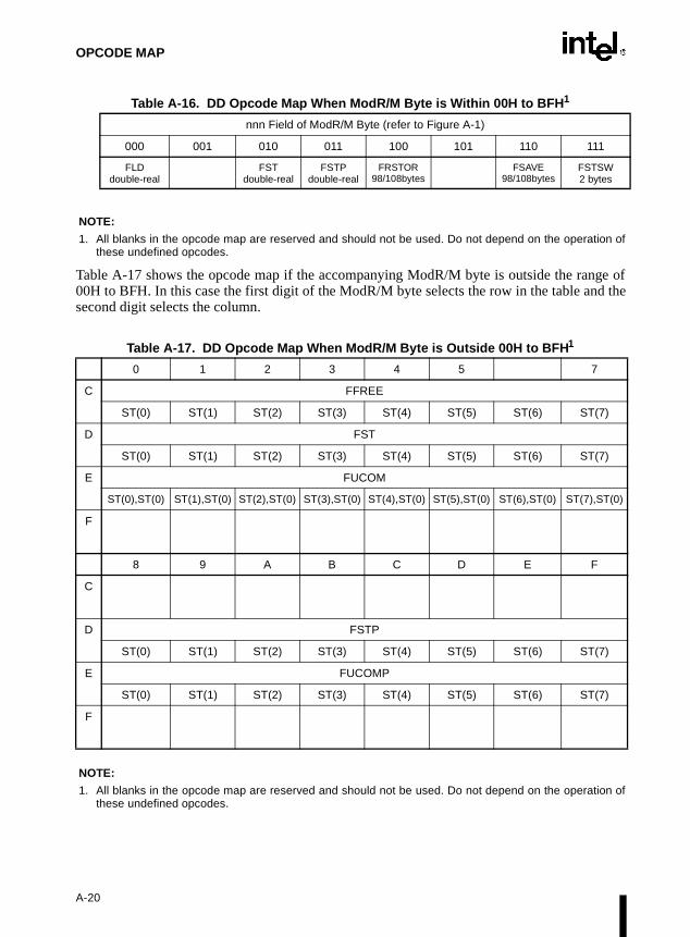
OPCODE MAP
Table A-16. DD Opcode Map When ModR/M Byte is Within 00H to BFH1
NOTE:
1. All blanks in the opcode map are reserved and should not be used. Do not depend on the operation ofthese undefined opcodes.
Table A-17 shows the opcode map if the accompanying ModR/M byte is outside the range of00H to BFH. In this case the first digit of the ModR/M byte selects the row in the table and thesecond digit selects the column.
Table A-17. DD Opcode Map When ModR/M Byte is Outside 00H to BFH1
NOTE:
1. All blanks in the opcode map are reserved and should not be used. Do not depend on the operation ofthese undefined opcodes.
nnn Field of ModR/M Byte (refer to Figure A-1)
000 001 010 011 100 101 110 111
FLD double-real
FST double-real
FSTP double-real
FRSTOR 98/108bytes
FSAVE 98/108bytes
FSTSW 2 bytes
0 1 2 3 4 5 7
C FFREE
ST(0) ST(1) ST(2) ST(3) ST(4) ST(5) ST(6) ST(7)
D FST
ST(0) ST(1) ST(2) ST(3) ST(4) ST(5) ST(6) ST(7)
E FUCOM
ST(0),ST(0) ST(1),ST(0) ST(2),ST(0) ST(3),ST(0) ST(4),ST(0) ST(5),ST(0) ST(6),ST(0) ST(7),ST(0)
F
8 9 A B C D E F
C
D FSTP
ST(0) ST(1) ST(2) ST(3) ST(4) ST(5) ST(6) ST(7)
E FUCOMP
ST(0) ST(1) ST(2) ST(3) ST(4) ST(5) ST(6) ST(7)
F
A-20
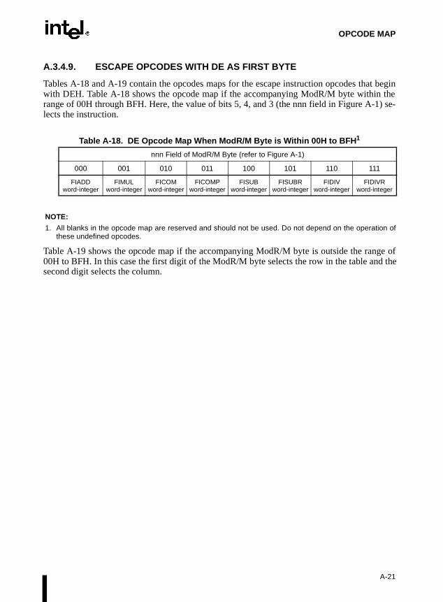
OPCODE MAP
A.3.4.9. ESCAPE OPCODES WITH DE AS FIRST BYTE
Tables A-18 and A-19 contain the opcodes maps for the escape instruction opcodes that beginwith DEH. Table A-18 shows the opcode map if the accompanying ModR/M byte within therange of 00H through BFH. Here, the value of bits 5, 4, and 3 (the nnn field in Figure A-1) se-lects the instruction.
Table A-18. DE Opcode Map When ModR/M Byte is Within 00H to BFH1
NOTE:
1. All blanks in the opcode map are reserved and should not be used. Do not depend on the operation ofthese undefined opcodes.
Table A-19 shows the opcode map if the accompanying ModR/M byte is outside the range of00H to BFH. In this case the first digit of the ModR/M byte selects the row in the table and thesecond digit selects the column.
nnn Field of ModR/M Byte (refer to Figure A-1)
000 001 010 011 100 101 110 111
FIADD word-integer
FIMUL word-integer
FICOM word-integer
FICOMP word-integer
FISUB word-integer
FISUBR word-integer
FIDIV word-integer
FIDIVR word-integer
A-21

OPCODE MAP
Table A-19. DE Opcode Map When ModR/M Byte is Outside 00H to BFH1
NOTE:
1. All blanks in the opcode map are reserved and should not be used. Do not depend on the operation ofthese undefined opcodes.
A.3.4.10. ESCAPE OPCODES WITH DF AS FIRST BYTE
Tables A-20 and A-21 contain the opcodes maps for the escape instruction opcodes that beginwith DFH. Table A-20 shows the opcode map if the accompanying ModR/M byte within therange of 00H through BFH. Here, the value of bits 5, 4, and 3 (the nnn field in Figure A-1) se-lects the instruction.
0 1 2 3 4 5 7
C FADDP
ST(0),ST(0) ST(1),ST(0) ST(2),ST(0) ST(3),ST(0) ST(4),ST(0) ST(5),ST(0) ST(6),ST(0) ST(7),ST(0)
D
E FSUBRP
ST(0),ST(0) ST(1),ST(0) ST(2),ST(0) ST(3),ST(0) ST(4),ST(0) ST(5),ST(0) ST(6),ST(0) ST(7),ST(0)
F FDIVRP
ST(0),ST(0) ST(1),ST(0) ST(2),ST(0) ST(3),ST(0) ST(4),ST(0) ST(5),ST(0) ST(6),ST(0) ST(7),ST(0)
8 9 A B C D E F
C FMULP
ST(0),ST(0) ST(1),ST(0) ST(2),ST(0) ST(3),ST(0) ST(4),ST(0) ST(5),ST(0) ST(6),ST(0) ST(7),ST(0)
D FCOMPP
E FSUBP
ST(0),ST(0) ST(1),ST(0) ST(2),ST(0) ST(3),ST(0) ST(4),ST(0) ST(5),ST(0) ST(6),ST(0) ST(7),ST(0)
F FDIVP
ST(0),ST(0) ST(1),ST(0) ST(2),ST(0). ST(3),ST(0) ST(4),ST(0) ST(5),ST(0) ST(6),ST(0) ST(7),ST(0)
A-22

OPCODE MAP
Table A-20. DF Opcode Map When ModR/M Byte is Within 00H to BFH1
NOTE:
1. All blanks in the opcode map are reserved and should not be used. Do not depend on the operation ofthese undefined opcodes.
Table A-21 shows the opcode map if the accompanying ModR/M byte is outside the range of00H to BFH. In this case the first digit of the ModR/M byte selects the row in the table and thesecond digit selects the column.
Table A-21. DF Opcode Map When ModR/M Byte is Outside 00H to BFH1
NOTE:
1. All blanks in the opcode map are reserved and should not be used. Do not depend on the operation ofthese undefined opcodes.
nnn Field of ModR/M Byte (refer to Figure A-1)
000 001 010 011 100 101 110 111
FILDword-integer
FIST word-integer
FISTP word-integer
FBLD packed-BCD
FILD qword-integer
FBSTP packed-BCD
FISTP qword-integer
0 1 2 3 4 5 7
C
D
E FSTSWAX
F FCOMIP
ST(0),ST(0) ST(0),ST(1) ST(0),ST(2) ST(0),ST(3) ST(0),ST(4) ST(0),ST(5) ST(0),ST(6) ST(0),ST(7)
8 9 A B C D E F
C
D
E FUCOMIP
ST(0),ST(0) ST(0),ST(1) ST(0),ST(2) ST(0),ST(3) ST(0),ST(4) ST(0),ST(5) ST(0),ST(6) ST(0),ST(7)
F
A-23

OPCODE MAP
A-24

B
Instruction Formats and Encodings

APPENDIX BINSTRUCTION FORMATS AND ENCODINGS
This appendix shows the formats and encodings of the Intel Architecture instructions. The mainformat and encoding tables are Tables B-10, B-14, B-20, and B-23.
B.1. MACHINE INSTRUCTION FORMAT
All Intel Architecture instructions are encoded using subsets of the general machine instructionformat shown in Figure B-1. Each instruction consists of an opcode, a register and/or addressmode specifier (if required) consisting of the ModR/M byte and sometimes the scale-index-base(SIB) byte, a displacement (if required), and an immediate data field (if required).
The primary opcode for an instruction is encoded in one or two bytes of the instruction. Someinstructions also use an opcode extension field encoded in bits 5, 4, and 3 of the ModR/M byte.Within the primary opcode, smaller encoding fields may be defined. These fields vary accordingto the class of operation being performed. The fields define such information as register encod-ing, conditional test performed, or sign extension of immediate byte.
Almost all instructions that refer to a register and/or memory operand have a register and/or ad-dress mode byte following the opcode. This byte, the ModR/M byte, consists of the mod field,the reg field, and the R/M field. Certain encodings of the ModR/M byte indicate that a secondaddress mode byte, the SIB byte, must be used.
If the selected addressing mode specifies a displacement, the displacement value is placed im-mediately following the ModR/M byte or SIB byte. If a displacement is present, the possible siz-es are 8, 16, or 32 bits.
If the instruction specifies an immediate operand, the immediate value follows any displacementbytes. An immediate operand, if specified, is always the last field of the instruction.
Figure B-1. General Machine Instruction Format
ModR/M Byte
7 6 5 4 3 2 1 0 7 6 5 4 3 2 1 0 7-6 5-3 2-07-6 5-3 2-0
T T T T T T T T T T T T T T T T Mod Reg* R/M Scale Index Base d32 | 16 | 8 | Noned32 | 16 | 8 | None
Opcode1 or 2 Bytes
(T Represents an Opcode Bit)
SIB Byte Address Displacement(4, 2, 1 Bytes or None)
Immediate Data(4,2,1 Bytes or None)
Register and/or AddressMode Specifier
* Reg Field is sometimes used asan opcode extension field (TTT).
B-1

INSTRUCTION FORMATS AND ENCODINGS
Table B-1 lists several smaller fields or bits that appear in certain instructions, sometimes withinthe opcode bytes themselves. The following tables describe these fields and bits and list the al-lowable values. All of these fields (except the d bit) are shown in the integer instruction formatsgiven in Table B-10.
B.1.1. Reg Field (reg)
The reg field in the ModR/M byte specifies a general-purpose register operand. The group ofregisters specified is modified by the presence of and state of the w bit in an encoding (refer toTable B-4). Table B-2 shows the encoding of the reg field when the w bit is not present in anencoding, and Table B-3 shows the encoding of the reg field when the w bit is present.
Table B-1. Special Fields Within Instruction Encodings
Field Name Description Number of Bits
reg General-register specifier (refer to Table B-2 or B-3) 3
w Specifies if data is byte or full-sized, where full-sized is either 16 or 32 bits (refer to Table B-4)
1
s Specifies sign extension of an immediate data field (refer to Table B-5) 1
sreg2 Segment register specifier for CS, SS, DS, ES (refer to Table B-6) 2
sreg3 Segment register specifier for CS, SS, DS, ES, FS, GS (refer to Table B-6)
3
eee Specifies a special-purpose (control or debug) register (refer to Table B-7)
3
tttn For conditional instructions, specifies a condition asserted or a condition negated (refer to Table B-8)
4
d Specifies direction of data operation (refer to Table B-9) 1
Table B-2. Encoding of reg Field When w Field is Not Present in Instruction
reg FieldRegister Selected during16-Bit Data Operations
Register Selected during32-Bit Data Operations
000 AX EAX
001 CX ECX
010 DX EDX
011 BX EBX
100 SP ESP
101 BP EBP
110 SI ESI
111 DI EDI
B-2

INSTRUCTION FORMATS AND ENCODINGS
B.1.2. Encoding of Operand Size Bit (w)
The current operand-size attribute determines whether the processor is performing 16-or 32-bitoperations. Within the constraints of the current operand-size attribute, the operand-size bit (w)can be used to indicate operations on 8-bit operands or the full operand size specified with theoperand-size attribute (16 bits or 32 bits). Table B-4 shows the encoding of the w bit dependingon the current operand-size attribute.
B.1.3. Sign Extend (s) Bit
The sign-extend (s) bit occurs primarily in instructions with immediate data fields that are beingextended from 8 bits to 16 or 32 bits. Table B-5 shows the encoding of the s bit.
Table B-3. Encoding of reg Field When w Field is Present in Instruction
Register Specified by reg Fieldduring 16-Bit Data Operations
Register Specified by reg Fieldduring 32-Bit Data Operations
Function of w Field Function of w Field
reg When w = 0 When w = 1 reg When w = 0 When w = 1
000 AL AX 000 AL EAX
001 CL CX 001 CL ECX
010 DL DX 010 DL EDX
011 BL BX 011 BL EBX
100 AH SP 100 AH ESP
101 CH BP 101 CH EBP
110 DH SI 110 DH ESI
111 BH DI 111 BH EDI
Table B-4. Encoding of Operand Size (w) Bit
w BitOperand Size When
Operand-Size Attribute is 16 bitsOperand Size When
Operand-Size Attribute is 32 bits
0 8 Bits 8 Bits
1 16 Bits 32 Bits
Table B-5. Encoding of Sign-Extend (s) Bit
sEffect on 8-Bit
Immediate DataEffect on 16- or 32-Bit
Immediate Data
0 None None
1 Sign-extend to fill 16-bit or 32-bit destination None
B-3

INSTRUCTION FORMATS AND ENCODINGS
B.1.4. Segment Register Field (sreg)
When an instruction operates on a segment register, the reg field in the ModR/M byte is calledthe sreg field and is used to specify the segment register. Table B-6 shows the encoding of thesreg field. This field is sometimes a 2-bit field (sreg2) and other times a 3-bit field (sreg3).
* Do not use reserved encodings.
B.1.5. Special-Purpose Register (eee) Field
When the control or debug registers are referenced in an instruction they are encoded in the eeefield, which is located in bits 5, 4, and 3 of the ModR/M byte. Table B-7 shows the encoding ofthe eee field.
* Do not use reserved encodings.
Table B-6. Encoding of the Segment Register (sreg) Field
2-Bit sreg2 FieldSegment Register
Selected 3-Bit sreg3 FieldSegment Register
Selected
00 ES 000 ES
01 CS 001 CS
10 SS 010 SS
11 DS 011 DS
100 FS
101 GS
110 Reserved*
111 Reserved*
Table B-7. Encoding of Special-Purpose Register (eee) Field
eee Control Register Debug Register
000 CR0 DR0
001 Reserved* DR1
010 CR2 DR2
011 CR3 DR3
100 CR4 Reserved*
101 Reserved* Reserved*
110 Reserved* DR6
111 Reserved* DR7
B-4

INSTRUCTION FORMATS AND ENCODINGS
given. first
B.1.6. Condition Test Field (tttn)
For conditional instructions (such as conditional jumps and set on condition), the condition testfield (tttn) is encoded for the condition being tested for. The ttt part of the field gives the condi-tion to test and the n part indicates whether to use the condition (n = 0) or its negation (n = 1).For 1-byte primary opcodes, the tttn field is located in bits 3,2,1, and 0 of the opcode byte; for2-byte primary opcodes, the tttn field is located in bits 3,2,1, and 0 of the second opcode byte.Table B-8 shows the encoding of the tttn field.
B.1.7. Direction (d) Bit
In many two-operand instructions, a direction bit (d) indicates which operand is considered thesource and which is the destination. Table B-9 shows the encoding of the d bit. When used forinteger instructions, the d bit is located at bit 1 of a 1-byte primary opcode. This bit does notappear as the symbol “d” in Table B-10; instead, the actual encoding of the bit as 1 or 0 isWhen used for floating-point instructions (in Table B-23), the d bit is shown as bit 2 of thebyte of the primary opcode.
Table B-8. Encoding of Conditional Test (tttn) Field
t t t n Mnemonic Condition
0000 O Overflow
0001 NO No overflow
0010 B, NAE Below, Not above or equal
0011 NB, AE Not below, Above or equal
0100 E, Z Equal, Zero
0101 NE, NZ Not equal, Not zero
0110 BE, NA Below or equal, Not above
0111 NBE, A Not below or equal, Above
1000 S Sign
1001 NS Not sign
1010 P, PE Parity, Parity Even
1011 NP, PO Not parity, Parity Odd
1100 L, NGE Less than, Not greater than or equal to
1101 NL, GE Not less than, Greater than or equal to
1110 LE, NG Less than or equal to, Not greater than
1111 NLE, G Not less than or equal to, Greater than
B-5

INSTRUCTION FORMATS AND ENCODINGS
.
B.2. INTEGER INSTRUCTION FORMATS AND ENCODINGS
Table B-10 shows the formats and encodings of the integer instructions.
Table B-9. Encoding of Operation Direction (d) Bit
d Source Destination
0 reg Field ModR/M or SIB Byte
1 ModR/M or SIB Byte reg Field
Table B-10. Integer Instruction Formats and Encodings
Instruction and Format Encoding
AAA – ASCII Adjust after Addition 0011 0111
AAD – ASCII Adjust AX before Division 1101 0101 : 0000 1010
AAM – ASCII Adjust AX after Multiply 1101 0100 : 0000 1010
AAS – ASCII Adjust AL after Subtraction 0011 1111
ADC – ADD with Carry
register1 to register2 0001 000w : 11 reg1 reg2
register2 to register1 0001 001w : 11 reg1 reg2
memory to register 0001 001w : mod reg r/m
register to memory 0001 000w : mod reg r/m
immediate to register 1000 00sw : 11 010 reg : immediate data
immediate to AL, AX, or EAX 0001 010w : immediate data
immediate to memory 1000 00sw : mod 010 r/m : immediate data
ADD – Add
register1 to register2 0000 000w : 11 reg1 reg2
register2 to register1 0000 001w : 11 reg1 reg2
memory to register 0000 001w : mod reg r/m
register to memory 0000 000w : mod reg r/m
immediate to register 1000 00sw : 11 000 reg : immediate data
immediate to AL, AX, or EAX 0000 010w : immediate data
immediate to memory 1000 00sw : mod 000 r/m : immediate data
B-6

INSTRUCTION FORMATS AND ENCODINGS
AND – Logical AND
register1 to register2 0010 000w : 11 reg1 reg2
register2 to register1 0010 001w : 11 reg1 reg2
memory to register 0010 001w : mod reg r/m
register to memory 0010 000w : mod reg r/m
immediate to register
immediate to AL, AX, or EAX 0010 010w : immediate data
immediate to memory 1000 00sw : mod 100 r/m : immediate data
ARPL – Adjust RPL Field of Selector
from register 0110 0011 : 11 reg1 reg2
from memory 0110 0011 : mod reg r/m
BOUND – Check Array Against Bounds 0110 0010 : mod reg r/m
BSF – Bit Scan Forward
register1, register2 0000 1111 : 1011 1100 : 11 reg2 reg1
memory, register 0000 1111 : 1011 1100 : mod reg r/m
BSR – Bit Scan Reverse
register1, register2 0000 1111 : 1011 1101 : 11 reg2 reg1
memory, register 0000 1111 : 1011 1101 : mod reg r/m
BSWAP – Byte Swap 0000 1111 : 1100 1 reg
BT – Bit Test
register, immediate 0000 1111 : 1011 1010 : 11 100 reg: imm8 data
memory, immediate 0000 1111 : 1011 1010 : mod 100 r/m : imm8 data
register1, register2 0000 1111 : 1010 0011 : 11 reg2 reg1
memory, reg 0000 1111 : 1010 0011 : mod reg r/m
BTC – Bit Test and Complemen t
register, immediate 0000 1111 : 1011 1010 : 11 111 reg: imm8 data
memory, immediate 0000 1111 : 1011 1010 : mod 111 r/m : imm8 data
register1, register2 0000 1111 : 1011 1011 : 11 reg2 reg1
memory, reg 0000 1111 : 1011 1011 : mod reg r/m
BTR – Bit Test and Reset
register, immediate 0000 1111 : 1011 1010 : 11 110 reg: imm8 data
memory, immediate 0000 1111 : 1011 1010 : mod 110 r/m : imm8 data
register1, register2 0000 1111 : 1011 0011 : 11 reg2 reg1
memory, reg 0000 1111 : 1011 0011 : mod reg r/m
Table B-10. Integer Instruction Formats and Encodings (Contd.)
Instruction and Format Encoding
B-7
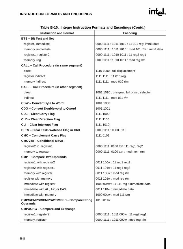
INSTRUCTION FORMATS AND ENCODINGS
BTS – Bit Test and Set
register, immediate 0000 1111 : 1011 1010 : 11 101 reg: imm8 data
memory, immediate 0000 1111 : 1011 1010 : mod 101 r/m : imm8 data
register1, register2 0000 1111 : 1010 1011 : 11 reg2 reg1
memory, reg 0000 1111 : 1010 1011 : mod reg r/m
CALL – Call Procedure (in same segment)
direct 1110 1000 : full displacement
register indirect 1111 1111 : 11 010 reg
memory indirect 1111 1111 : mod 010 r/m
CALL – Call Procedure (in other segment)
direct 1001 1010 : unsigned full offset, selector
indirect 1111 1111 : mod 011 r/m
CBW – Convert Byte to Word 1001 1000
CDQ – Convert Doubleword to Qword 1001 1001
CLC – Clear Carry Flag 1111 1000
CLD – Clear Direction Flag 1111 1100
CLI – Clear Interrupt Flag 1111 1010
CLTS – Clear Task-Switched Flag in CR0 0000 1111 : 0000 0110
CMC – Complement Carry Flag 1111 0101
CMOVcc – Conditional Move
register2 to register1 0000 1111: 0100 tttn : 11 reg1 reg2
memory to register 0000 1111: 0100 tttn : mod mem r/m
CMP – Compare Two Operands
register1 with register2 0011 100w : 11 reg1 reg2
register2 with register1 0011 101w : 11 reg1 reg2
memory with register 0011 100w : mod reg r/m
register with memory 0011 101w : mod reg r/m
immediate with register 1000 00sw : 11 111 reg : immediate data
immediate with AL, AX, or EAX 0011 110w : immediate data
immediate with memory 1000 00sw : mod 111 r/m
CMPS/CMPSB/CMPSW/CMPSD – Compare String Operands
1010 011w
CMPXCHG – Compare and Exchange
register1, register2 0000 1111 : 1011 000w : 11 reg2 reg1
memory, register 0000 1111 : 1011 000w : mod reg r/m
Table B-10. Integer Instruction Formats and Encodings (Contd.)
Instruction and Format Encoding
B-8

INSTRUCTION FORMATS AND ENCODINGS
CMPXCHG8B – Compare and Exchange 8 Bytes
memory, register 0000 1111 : 1100 0111 : mod reg r/m
CPUID – CPU Identification 0000 1111 : 1010 0010
CWD – Convert Word to Doubleword 1001 1001
CWDE – Convert Word to Doubleword 1001 1000
DAA – Decimal Adjust AL after Addition 0010 0111
DAS – Decimal Adjust AL after Subtraction 0010 1111
DEC – Decrement by 1
register 1111 111w : 11 001 reg
register (alternate encoding) 0100 1 reg
memory 1111 111w : mod 001 r/m
DIV – Unsigned Divide
AL, AX, or EAX by register 1111 011w : 11 110 reg
AL, AX, or EAX by memory 1111 011w : mod 110 r/m
ENTER – Make Stack Frame for High Level Procedure
1100 1000 : 16-bit displacement : 8-bit level (L)
HLT – Halt 1111 0100
IDIV – Signed Divide
AL, AX, or EAX by register 1111 011w : 11 111 reg
AL, AX, or EAX by memory 1111 011w : mod 111 r/m
IMUL – Signed Multiply
AL, AX, or EAX with register 1111 011w : 11 101 reg
AL, AX, or EAX with memory 1111 011w : mod 101 reg
register1 with register2 0000 1111 : 1010 1111 : 11 : reg1 reg2
register with memory 0000 1111 : 1010 1111 : mod reg r/m
register1 with immediate to register2 0110 10s1 : 11 reg1 reg2 : immediate data
memory with immediate to register 0110 10s1 : mod reg r/m : immediate data
IN – Input From Port
fixed port 1110 010w : port number
variable port 1110 110w
INC – Increment by 1
reg 1111 111w : 11 000 reg
reg (alternate encoding) 0100 0 reg
memory 1111 111w : mod 000 r/m
INS – Input from DX Port 0110 110w
Table B-10. Integer Instruction Formats and Encodings (Contd.)
Instruction and Format Encoding
B-9

INSTRUCTION FORMATS AND ENCODINGS
INT n – Interrupt Type n 1100 1101 : type
INT – Single-Step Interrupt 3 1100 1100
INTO – Interrupt 4 on Overflow 1100 1110
INVD – Invalidate Cache 0000 1111 : 0000 1000
INVLPG – Invalidate TLB Entry 0000 1111 : 0000 0001 : mod 111 r/m
IRET/IRETD – Interrupt Return 1100 1111
Jcc – Jump if Condition is Met
8-bit displacement 0111 tttn : 8-bit displacement
full displacement 0000 1111 : 1000 tttn : full displacement
JCXZ/JECXZ – Jump on CX/ECX Zero Address-size prefix differentiates JCXZ and JECXZ
1110 0011 : 8-bit displacement
JMP – Unconditional Jump (to same segment)
short 1110 1011 : 8-bit displacement
direct 1110 1001 : full displacement
register indirect 1111 1111 : 11 100 reg
memory indirect 1111 1111 : mod 100 r/m
JMP – Unconditional Jump (to other segment)
direct intersegment 1110 1010 : unsigned full offset, selector
indirect intersegment 1111 1111 : mod 101 r/m
LAHF – Load Flags into AHRegister 1001 1111
LAR – Load Access Rights Byte
from register 0000 1111 : 0000 0010 : 11 reg1 reg2
from memory 0000 1111 : 0000 0010 : mod reg r/m
LDS – Load Pointer to DS 1100 0101 : mod reg r/m
LEA – Load Effective Address 1000 1101 : mod reg r/m
LEAVE – High Level Procedure Exit 1100 1001
LES – Load Pointer to ES 1100 0100 : mod reg r/m
LFS – Load Pointer to FS 0000 1111 : 1011 0100 : mod reg r/m
LGDT – Load Global Descriptor Table Register 0000 1111 : 0000 0001 : mod 010 r/m
LGS – Load Pointer to GS 0000 1111 : 1011 0101 : mod reg r/m
LIDT – Load Interrupt Descriptor Table Register
LLDT – Load Local Descriptor Table Register
LDTR from register 0000 1111 : 0000 0000 : 11 010 reg
LDTR from memory 0000 1111 : 0000 0000 : mod 010 r/m
Table B-10. Integer Instruction Formats and Encodings (Contd.)
Instruction and Format Encoding
B-10

INSTRUCTION FORMATS AND ENCODINGS
LMSW – Load Machine Status Word
from register 0000 1111 : 0000 0001 : 11 110 reg
from memory 0000 1111 : 0000 0001 : mod 110 r/m
LOCK – Assert LOCK# Signal Prefix 1111 0000
LODS/LODSB/LODSW/LODSD – Load String Operand
1010 110w
LOOP – Loop Count 1110 0010 : 8-bit displacement
LOOPZ/LOOPE – Loop Count while Zero/Equal 1110 0001 : 8-bit displacement
LOOPNZ/LOOPNE – Loop Count while not Zero/Equal
1110 0000 : 8-bit displacement
LSL – Load Segment Limit
from register 0000 1111 : 0000 0011 : 11 reg1 reg2
from memory 0000 1111 : 0000 0011 : mod reg r/m
LSS – Load Pointer to SS 0000 1111 : 1011 0010 : mod reg r/m
LTR – Load Task Register
from register 0000 1111 : 0000 0000 : 11 011 reg
from memory 0000 1111 : 0000 0000 : mod 011 r/m
MOV – Move Data
register1 to register2 1000 100w : 11 reg1 reg2
register2 to register1 1000 101w : 11 reg1 reg2
memory to reg 1000 101w : mod reg r/m
reg to memory 1000 100w : mod reg r/m
immediate to register 1100 011w : 11 000 reg : immediate data
immediate to register (alternate encoding) 1011 w reg : immediate data
immediate to memory 1100 011w : mod 000 r/m : immediate data
memory to AL, AX, or EAX 1010 000w : full displacement
AL, AX, or EAX to memory 1010 001w : full displacement
MOV – Move to/from Control Registers
CR0 from register 0000 1111 : 0010 0010 : 11 000 reg
CR2 from register 0000 1111 : 0010 0010 : 11 010reg
CR3 from register 0000 1111 : 0010 0010 : 11 011 reg
CR4 from register 0000 1111 : 0010 0010 : 11 100 reg
register from CR0-CR4 0000 1111 : 0010 0000 : 11 eee reg
Table B-10. Integer Instruction Formats and Encodings (Contd.)
Instruction and Format Encoding
B-11

INSTRUCTION FORMATS AND ENCODINGS
MOV – Move to/from Debug Registers
DR0-DR3 from register 0000 1111 : 0010 0011 : 11 eee reg
DR4-DR5 from register 0000 1111 : 0010 0011 : 11 eee reg
DR6-DR7 from register 0000 1111 : 0010 0011 : 11 eee reg
register from DR6-DR7 0000 1111 : 0010 0001 : 11 eee reg
register from DR4-DR5 0000 1111 : 0010 0001 : 11 eee reg
register from DR0-DR3 0000 1111 : 0010 0001 : 11 eee reg
MOV – Move to/from Segment Registers
register to segment register 1000 1110 : 11 sreg3 reg
register to SS 1000 1110 : 11 sreg3 reg
memory to segment reg 1000 1110 : mod sreg3 r/m
memory to SS 1000 1110 : mod sreg3 r/m
segment register to register 1000 1100 : 11 sreg3 reg
segment register to memory 1000 1100 : mod sreg3 r/m
MOVS/MOVSB/MOVSW/MOVSD – Move Data from String to String
1010 010w
MOVSX – Move with Sign-Extend
register2 to register1 0000 1111 : 1011 111w : 11 reg1 reg2
memory to reg 0000 1111 : 1011 111w : mod reg r/m
MOVZX – Move with Zero-Extend
register2 to register1 0000 1111 : 1011 011w : 11 reg1 reg2
memory to register 0000 1111 : 1011 011w : mod reg r/m
MUL – Unsigned Multiply
AL, AX, or EAX with register 1111 011w : 11 100 reg
AL, AX, or EAX with memory 1111 011w : mod 100 reg
NEG – Two's Complement Negation
register 1111 011w : 11 011 reg
memory 1111 011w : mod 011 r/m
NOP – No Operation 1001 0000
NOT – One's Complement Negation
register 1111 011w : 11 010 reg
memory 1111 011w : mod 010 r/m
Table B-10. Integer Instruction Formats and Encodings (Contd.)
Instruction and Format Encoding
B-12

INSTRUCTION FORMATS AND ENCODINGS
OR – Logical Inclusive OR
register1 to register2 0000 100w : 11 reg1 reg2
register2 to register1 0000 101w : 11 reg1 reg2
memory to register 0000 101w : mod reg r/m
register to memory 0000 100w : mod reg r/m
immediate to register 1000 00sw : 11 001 reg : immediate data
immediate to AL, AX, or EAX 0000 110w : immediate data
immediate to memory 1000 00sw : mod 001 r/m : immediate data
OUT – Output to Port
fixed port 1110 011w : port number
variable port 1110 111w
OUTS – Output to DX Port 0110 111w
POP – Pop a Word from the Stack
register 1000 1111 : 11 000 reg
register (alternate encoding) 0101 1 reg
memory 1000 1111 : mod 000 r/m
POP – Pop a Segment Register from the Stack
segment register CS, DS, ES 000 sreg2 111
segment register SS 000 sreg2 111
segment register FS, GS 0000 1111: 10 sreg3 001
POPA/POPAD – Pop All General Registers 0110 0001
POPF/POPFD – Pop Stack into FLAGS or EFLAGS Register
1001 1101
PUSH – Push Operand onto the Stack
register 1111 1111 : 11 110 reg
register (alternate encoding) 0101 0 reg
memory 1111 1111 : mod 110 r/m
immediate 0110 10s0 : immediate data
PUSH – Push Segment Register onto the Stack
segment register CS,DS,ES,SS 000 sreg2 110
segment register FS,GS 0000 1111: 10 sreg3 000
PUSHA/PUSHAD – Push All General Registers 0110 0000
PUSHF/PUSHFD – Push Flags Register onto the Stack
1001 1100
Table B-10. Integer Instruction Formats and Encodings (Contd.)
Instruction and Format Encoding
B-13

INSTRUCTION FORMATS AND ENCODINGS
RCL – Rotate thru Carry Left
register by 1 1101 000w : 11 010 reg
memory by 1 1101 000w : mod 010 r/m
register by CL 1101 001w : 11 010 reg
memory by CL 1101 001w : mod 010 r/m
register by immediate count 1100 000w : 11 010 reg : imm8 data
memory by immediate count 1100 000w : mod 010 r/m : imm8 data
RCR – Rotate thru Carry Right
register by 1 1101 000w : 11 011 reg
memory by 1 1101 000w : mod 011 r/m
register by CL 1101 001w : 11 011 reg
memory by CL 1101 001w : mod 011 r/m
register by immediate count 1100 000w : 11 011 reg : imm8 data
memory by immediate count 1100 000w : mod 011 r/m : imm8 data
RDMSR – Read from Model-Specific Register 0000 1111 : 0011 0010
RDPMC – Read Performance Monitoring Counters
0000 1111 : 0011 0011
RDTSC – Read Time-Stamp Counter 0000 1111 : 0011 0001
REP INS – Input String 1111 0011 : 0110 110w
REP LODS – Load String 1111 0011 : 1010 110w
REP MOVS – Move String 1111 0011 : 1010 010w
REP OUTS – Output String 1111 0011 : 0110 111w
REP STOS – Store String 1111 0011 : 1010 101w
REPE CMPS – Compare String 1111 0011 : 1010 011w
REPE SCAS – Scan String 1111 0011 : 1010 111w
REPNE CMPS – Compare String 1111 0010 : 1010 011w
REPNE SCAS – Scan String 1111 0010 : 1010 111w
RET – Return from Procedure (to same segment)
no argument 1100 0011
adding immediate to SP 1100 0010 : 16-bit displacement
RET – Return from Procedure (to other segment)
intersegment 1100 1011
adding immediate to SP 1100 1010 : 16-bit displacement
Table B-10. Integer Instruction Formats and Encodings (Contd.)
Instruction and Format Encoding
B-14

INSTRUCTION FORMATS AND ENCODINGS
ROL – Rotate Left
register by 1 1101 000w : 11 000 reg
memory by 1 1101 000w : mod 000 r/m
register by CL 1101 001w : 11 000 reg
memory by CL 1101 001w : mod 000 r/m
register by immediate count 1100 000w : 11 000 reg : imm8 data
memory by immediate count 1100 000w : mod 000 r/m : imm8 data
ROR – Rotate Right
register by 1 1101 000w : 11 001 reg
memory by 1 1101 000w : mod 001 r/m
register by CL 1101 001w : 11 001 reg
memory by CL 1101 001w : mod 001 r/m
register by immediate count 1100 000w : 11 001 reg : imm8 data
memory by immediate count 1100 000w : mod 001 r/m : imm8 data
RSM – Resume from System Management Mode 0000 1111 : 1010 1010
SAHF – Store AH into Flags 1001 1110
SAL – Shift Arithmetic Left same instruction as SHL
SAR – Shift Arithmetic Right
register by 1 1101 000w : 11 111 reg
memory by 1 1101 000w : mod 111 r/m
register by CL 1101 001w : 11 111 reg
memory by CL 1101 001w : mod 111 r/m
register by immediate count 1100 000w : 11 111 reg : imm8 data
memory by immediate count 1100 000w : mod 111 r/m : imm8 data
SBB – Integer Subtraction with Borrow
register1 to register2 0001 100w : 11 reg1 reg2
register2 to register1 0001 101w : 11 reg1 reg2
memory to register 0001 101w : mod reg r/m
register to memory 0001 100w : mod reg r/m
immediate to register 1000 00sw : 11 011 reg : immediate data
immediate to AL, AX, or EAX 0001 110w : immediate data
immediate to memory 1000 00sw : mod 011 r/m : immediate data
SCAS/SCASB/SCASW/SCASD – Scan String 1101 111w
Table B-10. Integer Instruction Formats and Encodings (Contd.)
Instruction and Format Encoding
B-15

INSTRUCTION FORMATS AND ENCODINGS
SETcc – Byte Set on Condition
register 0000 1111 : 1001 tttn : 11 000 reg
memory 0000 1111 : 1001 tttn : mod 000 r/m
SGDT – Store Global Descriptor Table Register 0000 1111 : 0000 0001 : mod 000 r/m
SHL – Shift Left
register by 1 1101 000w : 11 100 reg
memory by 1 1101 000w : mod 100 r/m
register by CL 1101 001w : 11 100 reg
memory by CL 1101 001w : mod 100 r/m
register by immediate count 1100 000w : 11 100 reg : imm8 data
memory by immediate count 1100 000w : mod 100 r/m : imm8 data
SHLD – Double Precision Shift Left
register by immediate count 0000 1111 : 1010 0100 : 11 reg2 reg1 : imm8
memory by immediate count 0000 1111 : 1010 0100 : mod reg r/m : imm8
register by CL 0000 1111 : 1010 0101 : 11 reg2 reg1
memory by CL 0000 1111 : 1010 0101 : mod reg r/m
SHR – Shift Right
register by 1 1101 000w : 11 101 reg
memory by 1 1101 000w : mod 101 r/m
register by CL 1101 001w : 11 101 reg
memory by CL 1101 001w : mod 101 r/m
register by immediate count 1100 000w : 11 101 reg : imm8 data
memory by immediate count 1100 000w : mod 101 r/m : imm8 data
SHRD – Double Precision Shift Right
register by immediate count 0000 1111 : 1010 1100 : 11 reg2 reg1 : imm8
memory by immediate count 0000 1111 : 1010 1100 : mod reg r/m : imm8
register by CL 0000 1111 : 1010 1101 : 11 reg2 reg1
memory by CL 0000 1111 : 1010 1101 : mod reg r/m
SIDT – Store Interrupt Descriptor Table Register 0000 1111 : 0000 0001 : mod 001 r/m
SLDT – Store Local Descriptor Table Register
to register 0000 1111 : 0000 0000 : 11 000 reg
to memory 0000 1111 : 0000 0000 : mod 000 r/m
Table B-10. Integer Instruction Formats and Encodings (Contd.)
Instruction and Format Encoding
B-16

INSTRUCTION FORMATS AND ENCODINGS
SMSW – Store Machine Status Word
to register 0000 1111 : 0000 0001 : 11 100 reg
to memory 0000 1111 : 0000 0001 : mod 100 r/m
STC – Set Carry Flag 1111 1001
STD – Set Direction Flag 1111 1101
STI – Set Interrupt Flag 1111 1011
STOS/STOSB/STOSW/STOSD – Store String Data 1010 101w
STR – Store Task Register
to register 0000 1111 : 0000 0000 : 11 001 reg
to memory 0000 1111 : 0000 0000 : mod 001 r/m
SUB – Integer Subtraction
register1 to register2 0010 100w : 11 reg1 reg2
register2 to register1 0010 101w : 11 reg1 reg2
memory to register 0010 101w : mod reg r/m
register to memory 0010 100w : mod reg r/m
immediate to register 1000 00sw : 11 101 reg : immediate data
immediate to AL, AX, or EAX 0010 110w : immediate data
immediate to memory 1000 00sw : mod 101 r/m : immediate data
TEST – Logical Compare
register1 and register2 1000 010w : 11 reg1 reg2
memory and register 1000 010w : mod reg r/m
immediate and register 1111 011w : 11 000 reg : immediate data
immediate and AL, AX, or EAX 1010 100w : immediate data
immediate and memory 1111 011w : mod 000 r/m : immediate data
UD2 – Undefined instruction 0000 FFFF : 0000 1011
VERR – Verify a Segment for Reading
register 0000 1111 : 0000 0000 : 11 100 reg
memory 0000 1111 : 0000 0000 : mod 100 r/m
VERW – Verify a Segment for Writing
register 0000 1111 : 0000 0000 : 11 101 reg
memory 0000 1111 : 0000 0000 : mod 101 r/m
WAIT – Wait 1001 1011
WBINVD – Writeback and Invalidate Data Cache 0000 1111 : 0000 1001
WRMSR – Write to Model-Specific Register 0000 1111 : 0011 0000
Table B-10. Integer Instruction Formats and Encodings (Contd.)
Instruction and Format Encoding
B-17

INSTRUCTION FORMATS AND ENCODINGS
XADD – Exchange and Add
register1, register2 0000 1111 : 1100 000w : 11 reg2 reg1
memory, reg 0000 1111 : 1100 000w : mod reg r/m
XCHG – Exchange Register/Memory with Register
register1 with register2 1000 011w : 11 reg1 reg2
AL, AX, or EAX with reg 1001 0 reg
memory with reg 1000 011w : mod reg r/m
XLAT/XLATB – Table Look-up Translation 1101 0111
XOR – Logical Exclusive OR
register1 to register2 0011 000w : 11 reg1 reg2
register2 to register1 0011 001w : 11 reg1 reg2
memory to register 0011 001w : mod reg r/m
register to memory 0011 000w : mod reg r/m
immediate to register 1000 00sw : 11 110 reg : immediate data
immediate to AL, AX, or EAX 0011 010w : immediate data
immediate to memory 1000 00sw : mod 110 r/m : immediate data
Prefix Bytes
address size 0110 0111
LOCK 1111 0000
operand size 0110 0110
CS segment override 0010 1110
DS segment override 0011 1110
ES segment override 0010 0110
FS segment override 0110 0100
GS segment override 0110 0101
SS segment override 0011 0110
Table B-10. Integer Instruction Formats and Encodings (Contd.)
Instruction and Format Encoding
B-18

INSTRUCTION FORMATS AND ENCODINGS
ytesent- ef-
pter 2,
is op-. Table
in thee B-
B.3. MMX™ INSTRUCTION FORMATS AND ENCODINGS
All MMX™ instructions, except the EMMS instruction, use the a format similar to the 2-bIntel Architecture integer format. Details of subfield encodings within these formats are preed below. For information relating to the use of prefixes with MMX™ instructions, and thefects of these prefixes, see Section B.4.1. and Section 2.2., “Instruction Prefixes” in ChaInstruction Format.
B.3.1. Granularity Field (gg)
The granularity field (gg) indicates the size of the packed operands that the instruction erating on. When this field is used, it is located in bits 1 and 0 of the second opcode byteB-11 shows the encoding of this gg field.
B.3.2. MMX™ and General-Purpose Register Fields (mmxreg and reg)
When MMX™ technology registers (mmxreg) are used as operands, they are encodedModR/M byte in the reg field (bits 5, 4, and 3) and/or the R/M field (bits 2, 1, and 0). Tabl12 shows the 3-bit encodings used for mmxreg fields.
Table B-11. Encoding of Granularity of Data Field (gg)
gg Granularity of Data
00 Packed Bytes
01 Packed Words
10 Packed Doublewords
11 Quadword
Table B-12. Encoding of the MMX™ Register Field (mmxreg)
mmxreg Field Encoding MMX™ Register
000 MM0
001 MM1
010 MM2
011 MM3
100 MM4
101 MM5
110 MM6
111 MM7
B-19
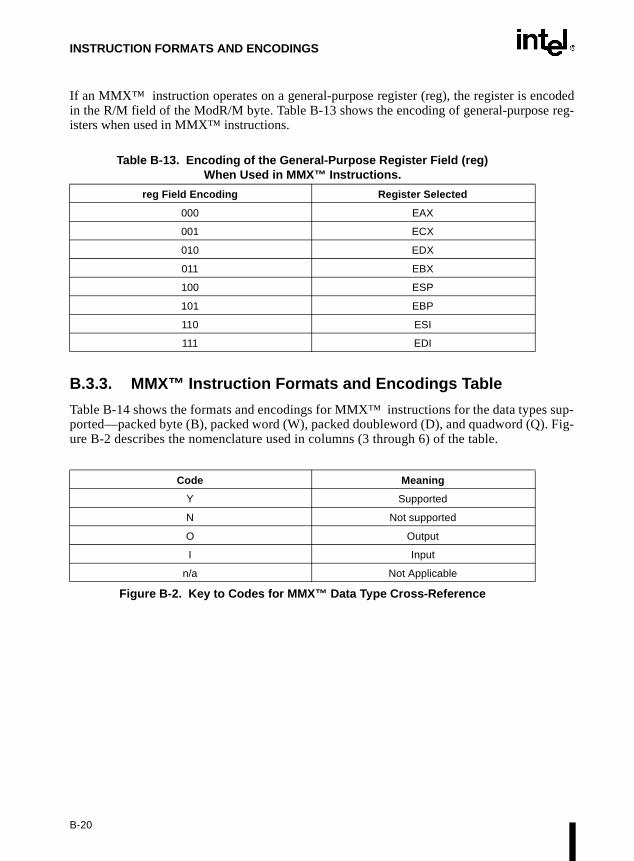
INSTRUCTION FORMATS AND ENCODINGS
coded reg-
-. Fig-
If an MMX™ instruction operates on a general-purpose register (reg), the register is enin the R/M field of the ModR/M byte. Table B-13 shows the encoding of general-purposeisters when used in MMX™ instructions.
B.3.3. MMX™ Instruction Formats and Encodings Table
Table B-14 shows the formats and encodings for MMX™ instructions for the data types supported—packed byte (B), packed word (W), packed doubleword (D), and quadword (Q)ure B-2 describes the nomenclature used in columns (3 through 6) of the table.
Table B-13. Encoding of the General-Purpose Register Field (reg) When Used in MMX™ Instructions.
reg Field Encoding Register Selected
000 EAX
001 ECX
010 EDX
011 EBX
100 ESP
101 EBP
110 ESI
111 EDI
Code Meaning
Y Supported
N Not supported
O Output
I Input
n/a Not Applicable
Figure B-2. Key to Codes for MMX™ Data Type Cross-Reference
B-20

INSTRUCTION FORMATS AND ENCODINGS
.
Table B-14. MMX™ Instruction Formats and Encodings
Instruction and Format Encoding B W D Q
EMMS - Empty MMX™ state 0000 1111:01110111 n/a n/a n/a n/a
MOVD - Move doubleword N N Y N
reg to mmreg 0000 1111:01101110: 11 mmxreg reg
reg from mmxreg 0000 1111:01111110: 11 mmxreg reg
mem to mmxreg 0000 1111:01101110: mod mmxreg r/m
mem from mmxreg 0000 1111:01111110: mod mmxreg r/m
MOVQ - Move quadword N N N Y
mmxreg2 to mmxreg1 0000 1111:01101111: 11 mmxreg1 mmxreg2
mmxreg2 from mmxreg1 0000 1111:01111111: 11 mmxreg1 mmxreg2
mem to mmxreg 0000 1111:01101111: mod mmxreg r/m
mem from mmxreg 0000 1111:01111111: mod mmxreg r/m
PACKSSDW 1 - Pack dword to word data (signed with saturation)
n/a O I n/a
mmxreg2 to mmxreg1 0000 1111:01101011: 11 mmxreg1 mmxreg2
memory to mmxreg 0000 1111:01101011: mod mmxreg r/m
PACKSSWB 1 - Pack word to byte data (signed with saturation)
O I n/a n/a
mmxreg2 to mmxreg1 0000 1111:01100011: 11 mmxreg1 mmxreg2
memory to mmxreg 0000 1111:01100011: mod mmxreg r/m
PACKUSWB 1 - Pack word to byte data (unsigned with saturation)
O I n/a n/a
mmxreg2 to mmxreg1 0000 1111:01100111: 11 mmxreg1 mmxreg2
memory to mmxreg 0000 1111:01100111: mod mmxreg r/m
PADD - Add with wrap-around Y Y Y N
mmxreg2 to mmxreg1 0000 1111: 111111gg: 11 mmxreg1 mmxreg2
memory to mmxreg 0000 1111: 111111gg: mod mmxreg r/m
PADDS - Add signed with saturation
Y Y N N
mmxreg2 to mmxreg1 0000 1111: 111011gg: 11 mmxreg1 mmxreg2
memory to mmxreg 0000 1111: 111011gg: mod mmxreg r/m
B-21

INSTRUCTION FORMATS AND ENCODINGS
PADDUS - Add unsigned with saturation
Y Y N N
mmxreg2 to mmxreg1 0000 1111: 110111gg: 11 mmxreg1 mmxreg2
memory to mmxreg 0000 1111: 110111gg: mod mmxreg r/m
PAND - Bitwise And N N N Y
mmxreg2 to mmxreg1 0000 1111:11011011: 11 mmxreg1 mmxreg2
memory to mmxreg 0000 1111:11011011: mod mmxreg r/m
PANDN - Bitwise AndNot N N N Y
mmxreg2 to mmxreg1 0000 1111:11011111: 11 mmxreg1 mmxreg2
memory to mmxreg 0000 1111:11011111: mod mmxreg r/m
PCMPEQ - Packed compare for equality
Y Y Y N
mmxreg1 with mmxreg2 0000 1111:011101gg: 11 mmxreg1 mmxreg2
mmxreg with memory 0000 1111:011101gg: mod mmxreg r/m
PCMPGT - Packed compare greater (signed)
Y Y Y N
mmxreg1 with mmxreg2 0000 1111:011001gg: 11 mmxreg1 mmxreg2
mmxreg with memory 0000 1111:011001gg: mod mmxreg r/m
PMADD - Packed multiply add n/a I O n/a
mmxreg2 to mmxreg1 0000 1111:11110101: 11 mmxreg1 mmxreg2
memory to mmxreg 0000 1111:11110101: mod mmxreg r/m
PMULH - Packed multiplication
N Y N N
mmxreg2 to mmxreg1 0000 1111:11100101: 11 mmxreg1 mmxreg2
memory to mmxreg 0000 1111:11100101: mod mmxreg r/m
PMULL - Packed multiplication
N Y N N
mmxreg2 to mmxreg1 0000 1111:11010101: 11 mmxreg1 mmxreg2
memory to mmxreg 0000 1111:11010101: mod mmxreg r/m
POR - Bitwise Or N N N Y
mmxreg2 to mmxreg1 0000 1111:11101011: 11 mmxreg1 mmxreg2
memory to mmxreg 0000 1111:11101011: mod mmxreg r/m
Table B-14. MMX™ Instruction Formats and Encodings (Contd.)
Instruction and Format Encoding B W D Q
B-22

INSTRUCTION FORMATS AND ENCODINGS
PSLL2 - Packed shift left logical
N Y Y Y
mmxreg1 by mmxreg2 0000 1111:111100gg: 11 mmxreg1 mmxreg2
mmxreg by memory 0000 1111:111100gg: mod mmxreg r/m
mmxreg by immediate 0000 1111:011100gg: 11 110 mmxreg: imm8 data
PSRA2 - Packed shift right arithmetic
N Y Y N
mmxreg1 by mmxreg2 0000 1111:111000gg: 11 mmxreg1 mmxreg2
mmxreg by memory 0000 1111:111000gg: mod mmxreg r/m
mmxreg by immediate 0000 1111:011100gg: 11 100 mmxreg: imm8 data
PSRL2 - Packed shift right logical
N Y Y Y
mmxreg1 by mmxreg2 0000 1111:110100gg: 11 mmxreg1 mmxreg2
mmxreg by memory 0000 1111:110100gg: mod mmxreg r/m
mmxreg by immediate 0000 1111:011100gg: 11 010 mmxreg: imm8 data
PSUB - Subtract with wrap-around
Y Y Y N
mmxreg2 from mmxreg1 0000 1111:111110gg: 11 mmxreg1 mmxreg2
memory from mmxreg 0000 1111:111110gg: mod mmxreg r/m
PSUBS - Subtract signed with saturation
Y Y N N
mmxreg2 from mmxreg1 0000 1111:111010gg: 11 mmxreg1 mmxreg2
memory from mmxreg 0000 1111:111010gg: mod mmxreg r/m
PSUBUS - Subtract unsigned with saturation
Y Y N N
mmxreg2 from mmxreg1 0000 1111:110110gg: 11 mmxreg1 mmxreg2
memory from mmxreg 0000 1111:110110gg: mod mmxreg r/m
PUNPCKH - Unpack high data to next larger type
Y Y Y N
mmxreg2 to mmxreg1 0000 1111:011010gg: 11 mmxreg1 mmxreg2
memory to mmxreg 0000 1111:011010gg: mod mmxreg r/m
Table B-14. MMX™ Instruction Formats and Encodings (Contd.)
Instruction and Format Encoding B W D Q
B-23
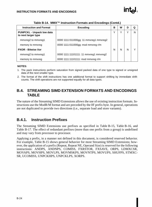
INSTRUCTION FORMATS AND ENCODINGS
NOTES:
1. The pack instructions perform saturation from signed packed data of one type to signed or unsigneddata of the next smaller type.
2. The format of the shift instructions has one additional format to support shifting by immediate shift-counts. The shift operations are not supported equally for all data types.
B.4. STREAMING SIMD EXTENSION FORMATS AND ENCODINGS TABLE
The nature of the Streaming SIMD Extensions allows the use of existing instruction formats. In-structions use the ModR/M format and are preceded by the 0F prefix byte. In general, operationsare not duplicated to provide two directions (i.e., separate load and store variants).
B.4.1. Instruction Prefixes
The Streaming SIMD Extensions use prefixes as specified in Table B-15, Table B-16, andTable B-17. The effect of redundant prefixes (more than one prefix from a group) is undefinedand may vary from processor to processor.
Applying a prefix, in a manner not defined in this document, is considered reserved behavior.For example, Table B-15 shows general behavior for most Streaming SIMD Extensions; how-ever, the application of a prefix (Repeat, Repeat NE, Operand Size) is reserved for the followinginstructions: ANDPS, ANDNPS, COMISS, FXRSTOR, FXSAVE, ORPS, LDMXCSR,MOVAPS, MOVHPS, MOVLPS, MOVMSKPS, MOVNTPS, MOVUPS, SHUFPS, STMXC-SR, UCOMISS, UNPCKHPS, UNPCKLPS, XORPS.
PUNPCKL - Unpack low data to next larger type
Y Y Y N
mmxreg2 to mmxreg1 0000 1111:011000gg: 11 mmxreg1 mmxreg2
memory to mmxreg 0000 1111:011000gg: mod mmxreg r/m
PXOR - Bitwise Xor N N N Y
mmxreg2 to mmxreg1 0000 1111:11101111: 11 mmxreg1 mmxreg2
memory to mmxreg 0000 1111:11101111: mod mmxreg r/m
Table B-14. MMX™ Instruction Formats and Encodings (Contd.)
Instruction and Format Encoding B W D Q
B-24

INSTRUCTION FORMATS AND ENCODINGS
Table B-15. Streaming SIMD Extensions Instruction Behavior with Prefixes
Table B-16. SIMD Integer Instructions - Behavior with Prefixes
Table B-17. Cacheability Control Instruction Behavior with Prefixes
Prefix Type Effect on Streaming SIMD Extensions
Address Size Prefix (67H) Affects Streaming SIMD Extensions with memory operandIgnored by Streaming SIMD Extensions without memory operand.
Operand Size (66H) Not supported and may result in undefined behavior.
Segment Override (2EH,36H,3EH,26H,64H,65H)
Affects Streaming SIMD Extensions with mem.operandIgnored by Streaming SIMD Extensions without mem operand
Repeat Prefix (F3H) Affects Streaming SIMD Extensions
Repeat NE Prefix(F2H) Not supported and may result in undefined behavior.
Lock Prefix (0F0H) Generates invalid opcode exception.
Prefix Type Effect on MMX™ Instructions
Address Size Prefix (67H) Affects MMX™ instructions with mem. operandIgnored by MMX™ instructions without mem. operand.
Operand Size (66H) Reserved and may result in unpredictable behavior.
Segment Override (2EH,36H,3EH,26H,64H,65H)
Affects MMX™ instructions with mem. operandIgnored by MMX™ instructions without mem operand
Repeat Prefix (F3H) Reserved and may result in unpredictable behavior.
Repeat NE Prefix(F2H) Reserved and may result in unpredictable behavior.
Lock Prefix (0F0H) Generates invalid opcode exception.
Prefix Type Effect on Streaming SIMD Extensions
Address Size Prefix (67H) Affects cacheability control instruction with a mem. operandIgnored by cacheability control instruction w/o a mem. operand.
Operand Size (66H) Ignored by PREFETCH and SFENCE. Not supported and may result in undefined behavior with MOVNTPS. Ignored by MOVNTQ and MASKMOVQ.
Segment Override (2EH,36H,3EH,26H,64H,65H)
Affects cacheability control instructions with mem. operandIgnored by cacheability control instruction without mem operand
Repeat Prefix(F3H) Ignored by PREFETCH and SFENCE instructions. Not supported and may result in undefined behavior with MOVNTPS. Ignored by MOVNTQ and MASKMOVQ.
Repeat NE Prefix(F2H) Ignored by PREFETCH and SFENCE instructions.Not supported and may result in undefined behavior with MOVNTPS. Ignored by MOVNTQ and MASKMOVQ.
Lock Prefix (0F0H) Generates an invalid opcode exception for all cacheability instructions.
B-25

INSTRUCTION FORMATS AND ENCODINGS
B.4.2. Notations
Besides opcodes, two kinds of notations are found which both describe information found in theModR/M byte:
/digit: (digit between 0 and 7) Indicates that the instruction uses only the r/m (register and memory)operand. The reg field contains the digit that provides an extensionto the instruction’s opcode.
/r Indicates that the ModR/M byte of an instruction contains both a reg-ister operand and an r/m operand.
In addition, the following abbreviations are used:
r32 Intel Architecture 32-bit integer register
xmm/m128 Indicates a 128-bit multimedia register or a 128-bit memory loca-tion.
xmm/m64 Indicates a 128-bit multimedia register or a 64-bit memory location.
xmm/m32 Indicates a 128-bit multimedia register or a 32-bit memory location.
mm/m64 Indicates a 64-bit multimedia register or a 64-bit memory location.
imm8 Indicates an immediate 8-bit operand.
ib Indicates that an immediate byte operand follows the opcode,ModR/M byte or scaled-indexing byte.
When there is ambiguity, xmm1 indicates the first source operand and xmm2 the second sourceoperand.
Table B-18 describes the naming conventions used in the Streaming SIMD Extensions mnemon-ics.
Table B-18. Key to Streaming SIMD Extensions Naming Convention
Mnemonic Description
PI Packed integer qword (e.g., mm0)
PS Packed single FP (e.g., xmm0)
SI Scalar integer (e.g., eax)
SS Scalar single-FP (e.g., low 32 bits of xmm0)
B-26

INSTRUCTION FORMATS AND ENCODINGS
quad-d re-
B-3
B.4.3. Formats and Encodings
The following three tables show the formats and encodings for Streaming SIMD Extensions forthe data types supported—packed byte (B), packed word (W), packed doubleword (D), word (Q), and double quadword (DQ). Table B-19, Table B-20, and Table B-21 corresponspectively to SIMD floating-point, SIMD-Integer, and Cacheability Register Fields. Figuredescribes the nomenclature used in columns (3 through 7) of the table.
Code Meaning
Y Supported
N Not supported
O Output
I Input
n/a Not Applicable
Figure B-3. Key to Codes for Streaming SIMD Extensions Data Type Cross-Reference
Table B-19. Encoding of the SIMD Floating-Point Register Field
Instruction and Format Encoding B W D Q DQ
ADDPS - Packed Single-FP Add
n/a n/a n/a n/a Y
xmmreg to xmmreg 00001111:01011000:11 xmmreg1 xmmreg2
mem to xmmreg 00001111:01011000: mod xmmreg r/m
ADDSS - Scalar Single-FP Add
n/a n/a Y n/a n/a
xmmreg to xmmreg 11110011:00001111:01011000:11 xmmreg1 xmmreg2
mem to xmmreg 11110011:00001111:01011000: mod xmmreg r/m
ANDNPS - Bit-wise Logical And Not for Single-FP
n/a n/a n/a n/a Y
xmmreg to xmmreg 00001111:01010101:11 xmmreg1 xmmreg2
mem to xmmreg 00001111:01010101: mod xmmreg r/m
ANDPS - Bit-wise Logical And for Single-FP
n/a n/a n/a n/a Y
xmmreg to xmmreg 00001111:01010100:11 xmmreg1 xmmreg2
mem to xmmreg 00001111:01010100: mod xmmreg r/m
CMPPS - Packed Single-FP Compare
n/a n/a n/a n/a Y
xmmreg to xmmreg, imm8 00001111:11000010:11 xmmreg1 xmmreg2: imm8
mem to xmmreg, imm8 00001111:11000010: mod xmmreg r/m: imm8
B-27

INSTRUCTION FORMATS AND ENCODINGS
CMPSS - Scalar Single-FP Compare
n/a n/a Y n/a n/a
xmmreg to xmmreg, imm8 11110011:00001111:11000010:11 xmmreg1 xmmreg2: imm8
mem to xmmreg, imm8 11110011:00001111:11000010: mod xmmreg r/m: imm8
COMISS - Scalar Ordered Single-FP compare and set EFLAGS
n/a n/a Y n/a n/a
xmmreg to xmmreg 00001111:00101111:11 xmmreg1 xmmreg2
mem to xmmreg 00001111:00101111: mod xmmreg r/m
CVTPI2PS - Packed signed INT32 to Packed Single-FP conversion
n/a n/a n/a n/a Y
mmreg to xmmreg 00001111:00101010:11 xmmreg1 mmreg1
mem to xmmreg 00001111:00101010: mod xmmreg r/m
CVTPS2PI - Packed Single-FP to Packed INT32 conversion
n/a n/a n/a n/a Y
xmmreg to mmreg 00001111:00101101:11 mmreg1 xmmreg1
mem to mmreg 00001111:00101101: mod mmreg r/m
CVTSI2SS - Scalar signed INT32 to Single-FP conversion
n/a n/a Y n/a n/a
r32 to xmmreg1 11110011:00001111:00101010:11 xmmreg r32
mem to xmmreg 11110011:00001111:00101010: mod xmmreg r/m
CVTSS2SI - Scalar Single-FP to signed INT32 conversion
n/a n/a Y n/a n/a
xmmreg to r32 11110011:00001111:00101101:11 r32 xmmreg
mem to r32 11110011:00001111:00101101: mod r32 r/m
CVTTPS2PI - Packed Single-FP to Packed INT32 Conversion (truncate)
n/a n/a n/a n/a Y
xmmreg to mmreg 00001111:00101100:11 mmreg1 xmmreg1
mem to mmreg 00001111:00101100: mod mmreg r/m
Table B-19. Encoding of the SIMD Floating-Point Register Field
Instruction and Format Encoding B W D Q DQ
B-28

INSTRUCTION FORMATS AND ENCODINGS
CVTTSS2SI - Scalar Single-FP to signed INT32 conversion (truncate)
n/a n/a Y n/a n/a
xmmreg to r32 11110011:00001111:00101100:11 r32 xmmreg1
mem to r32 11110011:00001111:00101100: mod r32 r/m
DIVPS - Packed Single-FP Divide
n/a n/a n/a n/a Y
xmmreg to xmmreg 00001111:01011110:11 xmmreg1 xmmreg2
mem to xmmreg 00001111:01011110: mod xmmreg r/m
DIVSS - Scalar Single-FP Divide
11110011:00001111:01011110:11 xmmreg1 xmmreg2
xmmreg to xmmreg n/a n/a Y n/a n/a
mem to xmmreg 11110011:00001111:01011110: mod xmmreg r/m
FXRSTOR - Restore FP/MMX™ and Streaming SIMD Extensions state
00001111:10101110:01 m512 n/a n/a n/a n/a n/a
FXSAVE - Store FP/MMX™ and Streaming SIMD Extensions state
00001111:10101110:00 m512 n/a n/a n/a n/a n/a
LDMXCSR - Load Streaming SIMD Extensions Technology Control/Status Register
n/a n/a n/a n/a n/a
m32 to MXCSR 00001111:10101110:10 m32
MAXPS - Packed Single-FP Maximum
n/a n/a n/a n/a Y
xmmreg to xmmreg 00001111:01011111:11 xmmreg1 xmmreg2
mem to xmmreg 00001111:01011111: mod xmmreg r/m
MAXSS - Scalar Single-FP Maximum
n/a n/a Y n/a n/a
xmmreg to xmmreg 11110011:00001111:01011111:11 xmmreg1 xmmreg2
mem to xmmreg 11110011:00001111:01011111: mod xmmreg r/m
MINPS - Packed Single-FP Minimum
n/a n/a n/a n/a Y
xmmreg to xmmreg 00001111:01011101:11 xmmreg1 xmmreg2
mem to xmmreg 00001111:01011101: mod xmmreg r/m
Table B-19. Encoding of the SIMD Floating-Point Register Field
Instruction and Format Encoding B W D Q DQ
B-29
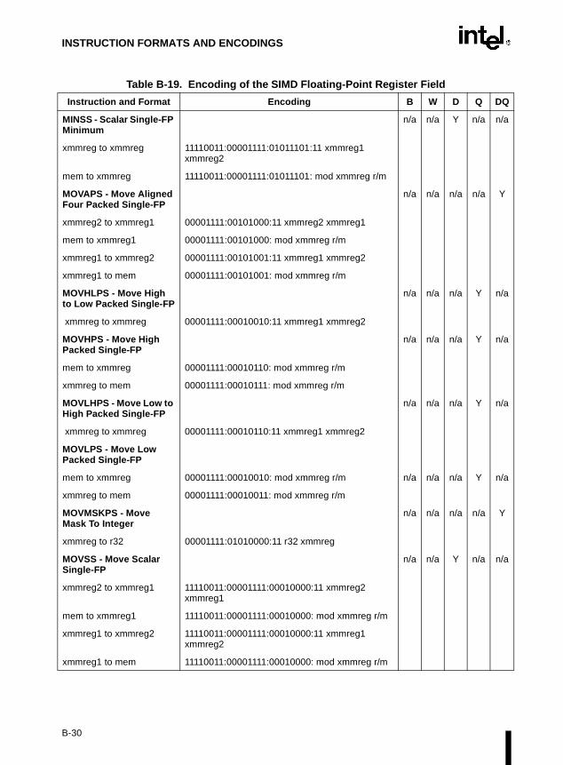
INSTRUCTION FORMATS AND ENCODINGS
MINSS - Scalar Single-FP Minimum
n/a n/a Y n/a n/a
xmmreg to xmmreg 11110011:00001111:01011101:11 xmmreg1 xmmreg2
mem to xmmreg 11110011:00001111:01011101: mod xmmreg r/m
MOVAPS - Move Aligned Four Packed Single-FP
n/a n/a n/a n/a Y
xmmreg2 to xmmreg1 00001111:00101000:11 xmmreg2 xmmreg1
mem to xmmreg1 00001111:00101000: mod xmmreg r/m
xmmreg1 to xmmreg2 00001111:00101001:11 xmmreg1 xmmreg2
xmmreg1 to mem 00001111:00101001: mod xmmreg r/m
MOVHLPS - Move High to Low Packed Single-FP
n/a n/a n/a Y n/a
xmmreg to xmmreg 00001111:00010010:11 xmmreg1 xmmreg2
MOVHPS - Move High Packed Single-FP
n/a n/a n/a Y n/a
mem to xmmreg 00001111:00010110: mod xmmreg r/m
xmmreg to mem 00001111:00010111: mod xmmreg r/m
MOVLHPS - Move Low to High Packed Single-FP
n/a n/a n/a Y n/a
xmmreg to xmmreg 00001111:00010110:11 xmmreg1 xmmreg2
MOVLPS - Move Low Packed Single-FP
mem to xmmreg 00001111:00010010: mod xmmreg r/m n/a n/a n/a Y n/a
xmmreg to mem 00001111:00010011: mod xmmreg r/m
MOVMSKPS - Move Mask To Integer
n/a n/a n/a n/a Y
xmmreg to r32 00001111:01010000:11 r32 xmmreg
MOVSS - Move Scalar Single-FP
n/a n/a Y n/a n/a
xmmreg2 to xmmreg1 11110011:00001111:00010000:11 xmmreg2 xmmreg1
mem to xmmreg1 11110011:00001111:00010000: mod xmmreg r/m
xmmreg1 to xmmreg2 11110011:00001111:00010000:11 xmmreg1 xmmreg2
xmmreg1 to mem 11110011:00001111:00010000: mod xmmreg r/m
Table B-19. Encoding of the SIMD Floating-Point Register Field
Instruction and Format Encoding B W D Q DQ
B-30

INSTRUCTION FORMATS AND ENCODINGS
MOVUPS - Move Unaligned Four Packed Single-FP
n/a n/a n/a n/a Y
xmmreg2 to xmmreg1 00001111:00010000:11 xmmreg2 xmmreg1
mem to xmmreg1 00001111:00010000: mod xmmreg r/m
xmmreg1 to xmmreg2 00001111:00010001:11 xmmreg1 xmmreg2
xmmreg1 to mem 00001111:00010001: mod xmmreg r/m
MULPS - Packed Single-FP Multiply
n/a n/a n/a n/a Y
xmmreg to xmmreg 00001111:01011001:11 xmmreg1 xmmreg2
mem to xmmreg 00001111:01011001: mod xmmreg rm
MULSS - Scalar Single-FP Multiply
n/a n/a Y n/a n/a
xmmreg to xmmreg 11110011:00001111:010111001:11 xmmreg1 xmmreg2
mem to xmmreg 11110011:00001111:010111001: mod xmmreg r/m
ORPS: Bit-wise Logical OR for Single-FP Data
n/a n/a n/a n/a Y
xmmreg to xmmreg 00001111:01010110:11 xmmreg1 xmmreg2
mem to xmmreg 00001111:01010110 mod xmmreg r/m
RCPPS - Packed Single-FP Reciprocal
n/a n/a n/a n/a Y
xmmreg to xmmreg 00001111:01010011:11 xmmreg1 xmmreg2
mem to xmmreg 00001111:01010011: mod xmmreg r/m
RCPSS - Scalar Single-FP Reciprocal
n/a n/a Y n/a n/a
xmmreg to xmmreg 11110011:00001111:01010011:11 xmmreg1 xmmreg2
mem to xmmreg 11110011:00001111:01010011: mod xmmreg r/m
RSQRTPS - Packed Single-FP Square Root Reciprocal
n/a n/a n/a n/a Y
xmmreg to xmmreg 00001111:01010010:11 xmmreg1 xmmreg2
mem to xmmreg 00001111:01010010 mode xmmreg r/m
Table B-19. Encoding of the SIMD Floating-Point Register Field
Instruction and Format Encoding B W D Q DQ
B-31

INSTRUCTION FORMATS AND ENCODINGS
RSQRTSS - Scalar Single-FP Square Root Reciprocal
n/a n/a Y n/a n/a
xmmreg to xmmreg 11110011:00001111:01010010:11 xmmreg1 xmmreg2
mem to xmmreg 11110011:00001111:01010010 mod xmmreg r/m
SHUFPS - Shuffle Single-FP
n/a n/a n/a n/a Y
xmmreg to xmmreg, imm8 00001111:11000110:11 xmmreg1 xmmreg2: imm8
mem to xmmreg, imm8 00001111:11000110: mod xmmreg r/m: imm8
SQRTPS - Packed Single-FP Square Root
n/a n/a n/a n/a Y
xmmreg to xmmreg 00001111:01010001:11 xmmreg1 xmmreg 2
mem to xmmreg 00001111:01010001 mod xmmreg r/m
SQRTSS - Scalar Single-FP Square Root
n/a n/a Y n/a n/a
xmmreg to xmmreg 01010011:00001111:01010001:11 xmmreg1 xmmreg 2
mem to xmmreg 01010011:00001111:01010001 mod xmmreg r/m
STMXCSR - Store Streaming SIMD Extensions Technology Control/Status Register
n/a n/a Y n/a n/a
MXCSR to mem 00001111:10101110:11 m32
SUBPS: Packed Single-FP Subtract
n/a n/a n/a n/a Y
xmmreg to xmmreg 00001111:01011100:11 xmmreg1 xmmreg2
mem to xmmreg 00001111:01011100 mod xmmreg r/m
SUBSS: Scalar Single-FP Subtract
n/a n/a Y n/a n/a
xmmreg to xmmreg 11110011:00001111:01011100:11 xmmreg1 xmmreg2
mem to xmmreg 11110011:00001111:01011100 mod xmmreg r/m
UCOMISS: Unordered Scalar Single-FP compare and set EFLAGS
n/a n/a Y n/a n/a
xmmreg to xmmreg 00001111:00101110:11 xmmreg1 xmmreg2
mem to xmmreg 00001111:00101110 mod xmmreg r/m
Table B-19. Encoding of the SIMD Floating-Point Register Field
Instruction and Format Encoding B W D Q DQ
B-32

INSTRUCTION FORMATS AND ENCODINGS
UNPCKHPS: Unpack High Packed Single-FP Data
n/a n/a n/a n/a Y
xmmreg to xmmreg 00001111:00010101:11 xmmreg1 xmmreg2
mem to xmmreg 00001111:00010101 mod xmmreg r/m
UNPCKLPS: Unpack Low Packed Single-FP Data
n/a n/a n/a n/a Y
xmmreg to xmmreg 00001111:00010100:11 xmmreg1 xmmreg2
mem to xmmreg 00001111:00010100 mod xmmreg r/m
XORPS: Bit-wise Logical Xor for Single-FP Data
n/a n/a n/a n/a Y
xmmreg to xmmreg 00001111:01010111:11 xmmreg1 xmmreg2
mem to xmmreg 00001111:01010111 mod xmmreg r/m
Table B-19. Encoding of the SIMD Floating-Point Register Field
Instruction and Format Encoding B W D Q DQ
B-33

INSTRUCTION FORMATS AND ENCODINGS
Table B-20. Encoding of the SIMD-Integer Register Field
Instruction and Format Encoding B W D Q DQ
PAVGB/PAVGW - Packed Average
Y Y n/a n/a n/a
mmreg to mmreg 00001111:11100000:11 mmreg1 mmreg2
00001111:11100011:11 mmreg1 mmreg2
mem to mmreg 00001111:11100000 mod mmreg r/m
00001111:11100011 mod mmreg r/m
PEXTRW - Extract Word n/a Y n/a n/a n/a
mmreg to reg32, imm8 00001111:11000101:11 mmreg r32: imm8
PINSRW - Insert Word n/a Y n/a n/a n/a
reg32 to mmreg, imm8 00001111:11000100:11 r32 mmreg1: imm8
m16 to mmreg, imm8 00001111:11000100 mod mmreg r/m: imm8
PMAXSW - Packed Signed Integer Word Maximum
n/a Y n/a n/a n/a
mmreg to mmreg 00001111:11101110:11 mmreg1 mmreg2
mem to mmreg 00001111:11101110 mod mmreg r/m
PMAXUB - Packed Unsigned Integer Byte Maximum
Y n/a n/a n/a n/a
mmreg to mmreg 00001111:11011110:11 mmreg1 mmreg2
mem to mmreg 00001111:11011110 mod mmreg r/m
PMINSW - Packed Signed Integer Word Minimum
n/a Y n/a n/a n/a
mmreg to mmreg 00001111:11101010:11 mmreg1 mmreg2
mem to mmreg 00001111:11101010 mod mmreg r/m
PMINUB - Packed Unsigned Integer Byte Minimum
Y’ n/a n/a n/a n/a
mmreg to mmreg 00001111:11011010:11 mmreg1 mmreg2
mem to mmreg 00001111:11011010 mod mmreg r/m
PMOVMSKB - Move Byte Mask To Integer
O n/a n/a I n/a
mmreg to reg32 00001111:11010111:11 mmreg1 r32
B-34

INSTRUCTION FORMATS AND ENCODINGS
PMULHUW - Packed Multiply High Unsigned
n/a O n/a I n/a
mmreg to mmreg 00001111:11100100:11 mmreg1 mmreg2
mem to mmreg 00001111:11100100 mod mmreg r/m
PSADBW - Packed Sum of Absolute Differences
I O n/a Y n/a
mmreg to mmreg 00001111:11110110:11 mmreg1 mmreg2
mem to mmreg 00001111:11110110 mod mmreg r/m
PSHUFW - Packed Shuffle Word
n/a Y n/a I n/a
mmreg to mmreg, imm8 00001111:01110000:11 mmreg1 mmreg2: imm8
mem to mmreg, imm8 00001111:01110000:11 mod mmreg r/m: imm8
Table B-21. Encoding of the Streaming SIMD Extensions Cacheability Control Register Field
Instruction and Format Encoding B W D Q DQ
MASKMOVQ - Byte Mask Write
n/a n/a n/a Y n/a
mmreg to mmreg 00001111:11110111:11 mmreg1 mmreg2
MOVNTPS - Move Aligned Four Packed Single-FP Non Temporal
n/a n/a n/a n/a Y
xmmreg to mem 00001111:00101011 mod xmmreg r/m
MOVNTQ - Move 64 Bits Non Temporal
n/a n/a n/a Y n/a
mmreg to mem 00001111:11100111 mod mmreg r/m
PREFETCHT0 - Prefetch to all cache levels
00001111:00011000:01 mem Y Y Y Y Y
PREFETCHT1 - Prefetch to all cache levels
00001111:00011000:10 mem Y Y Y Y Y
PREFETCHT2 - Prefetch to L2 cache
00001111:00011000:11 mem Y Y Y Y Y
PREFETCHNTA - Prefetch to L1 cache
00001111:00011000:00 mem Y Y Y Y Y
SFENCE - Store Fence 00001111:10101110:11111000 Y Y Y Y Y
Table B-20. Encoding of the SIMD-Integer Register Field
Instruction and Format Encoding B W D Q DQ
B-35
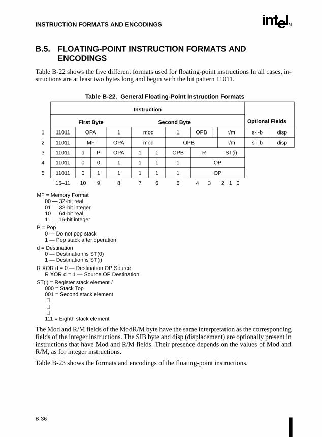
INSTRUCTION FORMATS AND ENCODINGS
B.5. FLOATING-POINT INSTRUCTION FORMATS AND ENCODINGS
Table B-22 shows the five different formats used for floating-point instructions In all cases, in-structions are at least two bytes long and begin with the bit pattern 11011.
MF = Memory Format00 — 32-bit real01 — 32-bit integer10 — 64-bit real11 — 16-bit integer
P = Pop0 — Do not pop stack1 — Pop stack after operation
d = Destination0 — Destination is ST(0)1 — Destination is ST(i)
R XOR d = 0 — Destination OP SourceR XOR d = 1 — Source OP Destination
ST(i) = Register stack element i000 = Stack Top001 = Second stack element ⋅ ⋅ ⋅111 = Eighth stack element
The Mod and R/M fields of the ModR/M byte have the same interpretation as the correspondingfields of the integer instructions. The SIB byte and disp (displacement) are optionally present ininstructions that have Mod and R/M fields. Their presence depends on the values of Mod andR/M, as for integer instructions.
Table B-23 shows the formats and encodings of the floating-point instructions.
Table B-22. General Floating-Point Instruction Formats
Instruction
First Byte Second Byte Optional Fields
1 11011 OPA 1 mod 1 OPB r/m s-i-b disp
2 11011 MF OPA mod OPB r/m s-i-b disp
3 11011 d P OPA 1 1 OPB R ST(i)
4 11011 0 0 1 1 1 1 OP
5 11011 0 1 1 1 1 1 OP
15–11 10 9 8 7 6 5 4 3 2 1 0
B-36

INSTRUCTION FORMATS AND ENCODINGS
Table B-23. Floating-Point Instruction Formats and EncodingsInstruction and Format Encoding
F2XM1 – Compute 2 ST(0) – 1 11011 001 : 1111 0000
FABS – Absolute Value 11011 001 : 1110 0001
FADD – Add
ST(0) ← ST(0) + 32-bit memory 11011 000 : mod 000 r/m
ST(0) ← ST(0) + 64-bit memory 11011 100 : mod 000 r/m
ST(d) ← ST(0) + ST(i) 11011 d00 : 11 000 ST(i)
FADDP – Add and Pop
ST(0) ← ST(0) + ST(i) 11011 110 : 11 000 ST(i)
FBLD – Load Binary Coded Decimal 11011 111 : mod 100 r/m
FBSTP – Store Binary Coded Decimal and Pop 11011 111 : mod 110 r/m
FCHS – Change Sign 11011 001 : 1110 0000
FCLEX – Clear Exceptions 11011 011 : 1110 0010
FCMOVcc – Conditional Move on EFLAG Register Condition Codes
move if below (B) 11011 010 : 11 000 ST(i)
move if equal (E) 11011 010 : 11 001 ST(i)
move if below or equal (BE) 11011 010 : 11 010 ST(i)
move if unordered (U) 11011 010 : 11 011 ST(i)
move if not below (NB) 11011 011 : 11 000 ST(i)
move if not equal (NE) 11011 011 : 11 001 ST(i)
move if not below or equal (NBE) 11011 011 : 11 010 ST(i)
move if not unordered (NU) 11011 011 : 11 011 ST(i)
FCOM – Compare Real
32-bit memory 11011 000 : mod 010 r/m
64-bit memory 11011 100 : mod 010 r/m
ST(i) 11011 000 : 11 010 ST(i)
FCOMP – Compare Real and Pop
32-bit memory 11011 000 : mod 011 r/m
64-bit memory 11011 100 : mod 011 r/m
ST(i) 11011 000 : 11 011 ST(i)
FCOMPP – Compare Real and Pop Twice 11011 110 : 11 011 001
FCOMI – Compare Real and Set EFLAGS 11011 011 : 11 110 ST(i)
FCOMIP – Compare Real, Set EFLAGS, and Pop 11011 111 : 11 110 ST(i)
FCOS – Cosine of ST(0) 11011 001 : 1111 1111
FDECSTP – Decrement Stack-Top Pointer 11011 001 : 1111 0110
FDIV – Divide
ST(0) ← ST(0) ÷ 32-bit memory 11011 000 : mod 110 r/m
ST(0) ← ST(0) ÷ 64-bit memory 11011 100 : mod 110 r/m
ST(d) ← ST(0) ÷ ST(i) 11011 d00 : 1111 R ST(i)
FDIVP – Divide and Pop
ST(0) ← ST(0) ÷ ST(i) 11011 110 : 1111 1 ST(i)
B-37

INSTRUCTION FORMATS AND ENCODINGS
FDIVR – Reverse Divide
ST(0) ← 32-bit memory ÷ ST(0) 11011 000 : mod 111 r/m
ST(0) ← 64-bit memory ÷ ST(0) 11011 100 : mod 111 r/m
ST(d) ← ST(i) ÷ ST(0) 11011 d00 : 1111 R ST(i)
FDIVRP – Reverse Divide and Pop
ST(0) ¨ ST(i) ÷ ST(0) 11011 110 : 1111 0 ST(i)
FFREE – Free ST(i) Register 11011 101 : 1100 0 ST(i)
FIADD – Add Integer
ST(0) ← ST(0) + 16-bit memory 11011 110 : mod 000 r/m
ST(0) ← ST(0) + 32-bit memory 11011 010 : mod 000 r/m
FICOM – Compare Integer
16-bit memory 11011 110 : mod 010 r/m
32-bit memory 11011 010 : mod 010 r/m
FICOMP – Compare Integer and Pop
16-bit memory 11011 110 : mod 011 r/m
32-bit memory 11011 010 : mod 011 r/m
FIDIV
ST(0) ← ST(0) + 16-bit memory 11011 110 : mod 110 r/m
ST(0) ← ST(0) + 32-bit memory 11011 010 : mod 110 r/m
FIDIVR
ST(0) ← ST(0) + 16-bit memory 11011 110 : mod 111 r/m
ST(0) ← ST(0) + 32-bit memory 11011 010 : mod 111 r/m
FILD – Load Integer
16-bit memory 11011 111 : mod 000 r/m
32-bit memory 11011 011 : mod 000 r/m
64-bit memory 11011 111 : mod 101 r/m
FIMUL
ST(0) ← ST(0) + 16-bit memory 11011 110 : mod 001 r/m
ST(0) ← ST(0) + 32-bit memory 11011 010 : mod 001 r/m
FINCSTP – Increment Stack Pointer 11011 001 : 1111 0111
FINIT – Initialize Floating-Point Unit
FIST – Store Integer
16-bit memory 11011 111 : mod 010 r/m
32-bit memory 11011 011 : mod 010 r/m
FISTP – Store Integer and Pop
16-bit memory 11011 111 : mod 011 r/m
32-bit memory 11011 011 : mod 011 r/m
64-bit memory 11011 111 : mod 111 r/m
FISUB
ST(0) ← ST(0) + 16-bit memory 11011 110 : mod 100 r/m
ST(0) ← ST(0) + 32-bit memory 11011 010 : mod 100 r/m
Table B-23. Floating-Point Instruction Formats and EncodingsInstruction and Format Encoding
B-38

INSTRUCTION FORMATS AND ENCODINGS
FISUBR
ST(0) ← ST(0) + 16-bit memory 11011 110 : mod 101 r/m
ST(0) ← ST(0) + 32-bit memory 11011 010 : mod 101 r/m
FLD – Load Real
32-bit memory 11011 001 : mod 000 r/m
64-bit memory 11011 101 : mod 000 r/m
80-bit memory 11011 011 : mod 101 r/m
ST(i) 11011 001 : 11 000 ST(i)
FLD1 – Load +1.0 into ST(0) 11011 001 : 1110 1000
FLDCW – Load Control Word 11011 001 : mod 101 r/m
FLDENV – Load FPU Environment 11011 001 : mod 100 r/m
FLDL2E – Load log 2(ε) into ST(0) 11011 001 : 1110 1010
FLDL2T – Load log 2(10) into ST(0) 11011 001 : 1110 1001
FLDLG2 – Load log 10(2) into ST(0) 11011 001 : 1110 1100
FLDLN2 – Load log ε(2) into ST(0) 11011 001 : 1110 1101
FLDPI – Load π into ST(0) 11011 001 : 1110 1011
FLDZ – Load +0.0 into ST(0) 11011 001 : 1110 1110
FMUL – Multiply
ST(0) ← ST(0) × 32-bit memory 11011 000 : mod 001 r/m
ST(0) ← ST(0) × 64-bit memory 11011 100 : mod 001 r/m
ST(d) ← ST(0) × ST(i) 11011 d00 : 1100 1 ST(i)
FMULP – Multiply
ST(0) ← ST(0) × ST(i) 11011 110 : 1100 1 ST(i)
FNOP – No Operation 11011 001 : 1101 0000
FPATAN – Partial Arctangent 11011 001 : 1111 0011
FPREM – Partial Remainder 11011 001 : 1111 1000
FPREM1 – Partial Remainder (IEEE) 11011 001 : 1111 0101
FPTAN – Partial Tangent 11011 001 : 1111 0010
FRNDINT – Round to Integer 11011 001 : 1111 1100
FRSTOR – Restore FPU State 11011 101 : mod 100 r/m
FSAVE – Store FPU State 11011 101 : mod 110 r/m
FSCALE – Scale 11011 001 : 1111 1101
FSIN – Sine 11011 001 : 1111 1110
FSINCOS – Sine and Cosine 11011 001 : 1111 1011
FSQRT – Square Root 11011 001 : 1111 1010
FST – Store Real
32-bit memory 11011 001 : mod 010 r/m
64-bit memory 11011 101 : mod 010 r/m
ST(i) 11011 101 : 11 010 ST(i)
FSTCW – Store Control Word 11011 001 : mod 111 r/m
FSTENV – Store FPU Environment 11011 001 : mod 110 r/m
Table B-23. Floating-Point Instruction Formats and EncodingsInstruction and Format Encoding
B-39
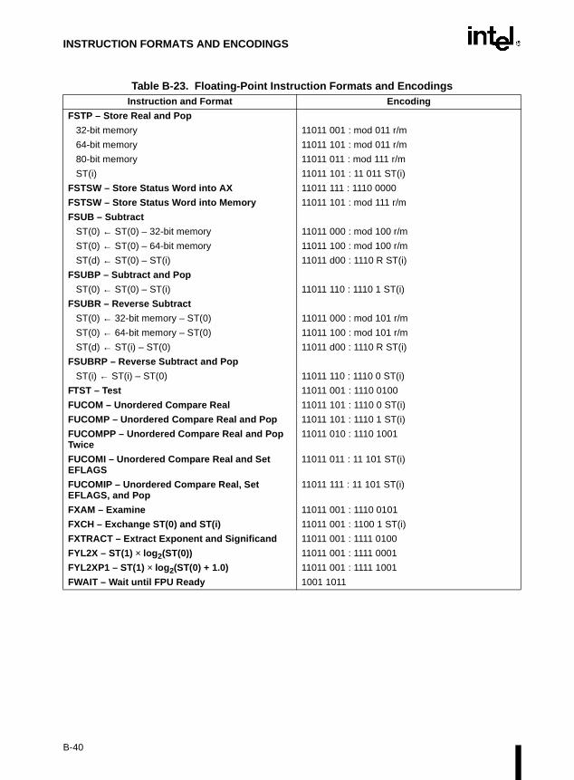
INSTRUCTION FORMATS AND ENCODINGS
FSTP – Store Real and Pop
32-bit memory 11011 001 : mod 011 r/m
64-bit memory 11011 101 : mod 011 r/m
80-bit memory 11011 011 : mod 111 r/m
ST(i) 11011 101 : 11 011 ST(i)
FSTSW – Store Status Word into AX 11011 111 : 1110 0000
FSTSW – Store Status Word into Memory 11011 101 : mod 111 r/m
FSUB – Subtract
ST(0) ← ST(0) – 32-bit memory 11011 000 : mod 100 r/m
ST(0) ← ST(0) – 64-bit memory 11011 100 : mod 100 r/m
ST(d) ← ST(0) – ST(i) 11011 d00 : 1110 R ST(i)
FSUBP – Subtract and Pop
ST(0) ← ST(0) – ST(i) 11011 110 : 1110 1 ST(i)
FSUBR – Reverse Subtract
ST(0) ← 32-bit memory – ST(0) 11011 000 : mod 101 r/m
ST(0) ← 64-bit memory – ST(0) 11011 100 : mod 101 r/m
ST(d) ← ST(i) – ST(0) 11011 d00 : 1110 R ST(i)
FSUBRP – Reverse Subtract and Pop
ST(i) ← ST(i) – ST(0) 11011 110 : 1110 0 ST(i)
FTST – Test 11011 001 : 1110 0100
FUCOM – Unordered Compare Real 11011 101 : 1110 0 ST(i)
FUCOMP – Unordered Compare Real and Pop 11011 101 : 1110 1 ST(i)
FUCOMPP – Unordered Compare Real and Pop Twice
11011 010 : 1110 1001
FUCOMI – Unordered Compare Real and Set EFLAGS
11011 011 : 11 101 ST(i)
FUCOMIP – Unordered Compare Real, Set EFLAGS, and Pop
11011 111 : 11 101 ST(i)
FXAM – Examine 11011 001 : 1110 0101
FXCH – Exchange ST(0) and ST(i) 11011 001 : 1100 1 ST(i)
FXTRACT – Extract Exponent and Significand 11011 001 : 1111 0100
FYL2X – ST(1) × log 2(ST(0)) 11011 001 : 1111 0001
FYL2XP1 – ST(1) × log 2(ST(0) + 1.0) 11011 001 : 1111 1001
FWAIT – Wait until FPU Ready 1001 1011
Table B-23. Floating-Point Instruction Formats and EncodingsInstruction and Format Encoding
B-40

C
Compiler Intrinsics and Functional Equivalents

y rec-f sup-
h
intrin-.
amesr ver-ersionnsicrsion
n’s
APPENDIX CCOMPILER INTRINSICS AND FUNCTIONAL
EQUIVALENTS
The two tables in this chapter itemize the Intel C/C++ compiler intrinsics and functional equiv-alents for the MMX™ technology instructions and Streaming SIMD Extensions.
There may be additional intrinsics that do not have an instruction equivalent. It is stronglommended that the reader reference the compiler documentation for the complete list oported intrinsics. Please refer to the Intel C/C++ Compiler User’s Guide for Win32* Systems WitStreaming SIMD Extension Support (Order Number 718195-00B). Appendix C catalogs use of theseintrinsics.
The Section 3.1.3., “Intel C/C++ Compiler Intrinsics Equivalent” of Chapter 3, Instruction SetReference has more general supporting information for the following tables.
Table C-1 presents simple intrinsics, and Table C-2 presents composite intrinsics. Somesics are “composites” because they require more than one instruction to implement them
Most of the intrinsics that use __m64 operands have two different names. If two intrinsic nare shown for the same equivalent, the first name is the intrinsic for Intel C/C++ Compilesions prior to 4.0 and the second name should be used with the Intel C/C++ Compiler v4.0 and future versions. The Intel C/C++ Compiler version 4.0 will support the old intrinames. Programs written using pre-4.0 intrinsic names will compile with version 4.0. Ve4.0 intrinsic names will not compile on pre-4.0 compilers.
Intel C/C++ Compiler version 4.0 names reflect the following naming conventions:
• a "_mm" prefix, followed by a plain spelling of the operation or the actual instructiomnemonic, followed by a suffix indicating the operand type.
• Since there are many different types of integer data that can be contained within a __m64data item, the following convention is used:
• s - indicates scalar
• p - indicates packed
• i - indicates signed integer, or in some instructions where the sign does not matter,this is the default
• u - indicates an unsigned integer
• 8, 16, 32, or 64 - the bit size of the data elements.
For example, _mm_add_pi8 indicates addition of packed, 8-bit integers; _mm_slli_pi32() is alogical left shift with an immediate shift count (the "i" after the name) of a packed, 32-bit integer.
C-1

COMPILER INTRINSICS AND FUNCTIONAL EQUIVALENTS
C.1. SIMPLE INTRINSICS
Table C-1. Simple Intrinsics
Mnemonic Intrinsic Description
ADDPS __m128 _mm_add_ps(__m128 a, __m128 b) Adds the four SP FP values of a and b.
ADDSS __m128 _mm_add_ss(__m128 a, __m128 b) Adds the lower SP FP (single-precision, floating-point) values of a and b; the upper three SP FP values are passed through from a.
ANDPS __m128 _mm_andnot_ps(__m128 a, __m128 b) Computes the bitwise AND-NOT of the four SP FP values of a and b.
CMPPS __m128 _mm_cmpeq_ps(__m128 a, __m128 b) Compare for equality.
__m128 _mm_cmplt_ps(__m128 a, __m128 b) Compare for less-than.
__m128 _mm_cmple_ps(__m128 a, __m128 b) Compare for less-than-or-equal.
__m128 _mm_cmpgt_ps(__m128 a, __m128 b) Compare for greater-than.
__m128 _mm_cmpge_ps(__m128 a, __m128 b) Compare for greater-than-or-equal.
__m128 _mm_cmpneq_ps(__m128 a, __m128 b) Compare for inequality.
__m128 _mm_cmpnlt_ps(__m128 a, __m128 b) Compare for not-less-than.
__m128 _mm_cmpngt_ps(__m128 a, __m128 b) Compare for not-greater-than.
__m128 _mm_cmpnge_ps(__m128 a, __m128 b) Compare for not-greater-than-or-equal.
__m128 _mm_cmpord_ps(__m128 a, __m128 b) Compare for ordered.
__m128 _mm_cmpunord_ps(__m128 a, __m128 b) Compare for unordered.
__m128 _mm_cmpnle_ps(__m128 a, __m128 b) Compare for not-less-than-or-equal.
CMPSS __m128 _mm_cmpeq_ss(__m128 a, __m128 b) Compare for equality.
__m128 _mm_cmplt_ss(__m128 a, __m128 b) Compare for less-than.
__m128 _mm_cmple_ss(__m128 a, __m128 b) Compare for less-than-or-equal.
__m128 _mm_cmpgt_ss(__m128 a, __m128 b) Compare for greater-than.
__m128 _mm_cmpge_ss(__m128 a, __m128 b) Compare for greater-than-or-equal.
__m128 _mm_cmpneq_ss(__m128 a, __m128 b) Compare for inequality.
__m128 _mm_cmpnlt_ss(__m128 a, __m128 b) Compare for not-less-than.
__m128 _mm_cmpnle_ss(__m128 a, __m128 b) Compare for not-greater-than.
__m128 _mm_cmpngt_ss(__m128 a, __m128 b) Compare for not-greater-than-or-equal.
__m128 _mm_cmpnge_ss(__m128 a, __m128 b) Compare for ordered.
__m128 _mm_cmpord_ss(__m128 a, __m128 b) Compare for unordered.
__m128 _mm_cmpunord_ss(__m128 a, __m128 b) Compare for not-less-than-or-equal.
C-2

COMPILER INTRINSICS AND FUNCTIONAL EQUIVALENTS
COMISS int _mm_comieq_ss(__m128 a, __m128 b) Compares the lower SP FP value of a and b for a equal to b. If a and b are equal, 1 is returned. Otherwise 0 is returned.
int _mm_comilt_ss(__m128 a, __m128 b) Compares the lower SP FP value of a and b for a less than b. If a is less than b, 1 is returned. Otherwise 0 is returned.
int _mm_comile_ss(__m128 a, __m128 b) Compares the lower SP FP value of a and b for a less than or equal to b. If a is less than or equal to b, 1 is returned. Otherwise 0 is returned.
int _mm_comigt_ss(__m128 a, __m128 b) Compares the lower SP FP value of a and b for a greater than b. If a is greater than b are equal, 1 is returned. Otherwise 0 is returned.
int _mm_comige_ss(__m128 a, __m128 b) Compares the lower SP FP value of a and b for a greater than or equal to b. If a is greater than or equal to b, 1 is returned. Otherwise 0 is returned.
int _mm_comineq_ss(__m128 a, __m128 b) Compares the lower SP FP value of a and b for a not equal to b. If a and b are not equal, 1 is returned. Otherwise 0 is returned.
CVTPI2PS __m128 _mm_cvt_pi2ps(__m128 a, __m64 b)__m128 _mm_cvtpi32_ps(__m128 a, __m64b)
Convert the two 32-bit integer values in packed form in b to two SP FP values; the upper two SP FP values are passed through from a.
CVTPS2PI __m64 _mm_cvt_ps2pi(__m128 a)__m64 _mm_cvtps_pi32(__m128 a)
Convert the two lower SP FP values of a to two 32-bit integers according to the current rounding mode, returning the integers in packed form.
CVTSI2SS __m128 _mm_cvt_si2ss(__m128 a, int b)__m128 _mm_cvtsi32_ss(__m128a, int b)
Convert the 32-bit integer value b to an SP FP value; the upper three SP FP values are passed through from a.
CVTSS2SI int _mm_cvt_ss2si(__m128 a)int _mm_cvtss_si32(__m128 a)
Convert the lower SP FP value of a to a 32-bit integer with truncation.
CVTTPS2PI __m64 _mm_cvtt_ps2pi(__m128 a)__m64 _mm_cvttps_pi32(__m128 a)
Convert the two lower SP FP values of a to two 32-bit integer with truncation, returning the integers in packed form.
CVTTSS2SI int _mm_cvtt_ss2si(__m128 a)int _mm_cvttss_si32(__m128 a)
Convert the lower SP FP value of a to a 32-bit integer according to the current rounding mode.
__m64 _m_from_int(int i)__m64 _mm_cvtsi32_si64(int i)
Convert the integer object i to a 64-bit __m64 object. The integer value is zero extended to 64 bits.
int _m_to_int(__m64 m)int _mm_cvtsi64_si32(__m64 m)
Convert the lower 32 bits of the __m64 object m to an integer.
DIVPS __m128 _mm_div_ps(__m128 a, __m128 b) Divides the four SP FP values of a and b.
DIVSS __m128 _mm_div_ss(__m128 a, __m128 b) Divides the lower SP FP values of a and b; the upper three SP FP values are passed through from a.
EMMS void _m_empty()void _mm_empty()
Clears the MMX™ technology state.
Table C-1. Simple Intrinsics
Mnemonic Intrinsic Description
C-3

COMPILER INTRINSICS AND FUNCTIONAL EQUIVALENTS
LDMXCSR _mm_setcsr(unsigned int i) Sets the control register to the value specified.
MASKMOVQ void _m_maskmovq(__m64 d, __m64 n, char * p)void _mm_maskmove_si64(__m64 d, __m64 n, char *p)
Conditionally store byte elements of d to address p. The high bit of each byte in the selector n determines whether the corresponding byte in d will be stored.
MAXPS __m128 _mm_max_ps(__m128 a, __m128 b) Computes the maximums of the four SP FP values of a and b.
MAXSS __m128 _mm_max_ss(__m128 a, __m128 b) Computes the maximum of the lower SP FP values of a and b; the upper three SP FP values are passed through from a.
MINPS __m128 _mm_min_ps(__m128 a, __m128 b) Computes the minimums of the four SP FP values of a and b.
MINSS __m128 _mm_min_ss(__m128 a, __m128 b) Computes the minimum of the lower SP FP values of a and b; the upper three SP FP values are passed through from a.
MOVAPS __m128 _mm_load_ps(float * p) Loads four SP FP values. The address must be 16-byte-aligned.
void_mm_store_ps(float *p, __m128 a) Stores four SP FP values. The address must be 16-byte-aligned.
MOVHLPS __m128 _mm_movehl_ps(__m128 a, __m128 b) Moves the upper 2 SP FP values of b to the lower 2 SP FP values of the result. The upper 2 SP FP values of a are passed through to the result.
MOVHPS __m128 _mm_loadh_pi(__m128 a, __m64 * p) Sets the upper two SP FP values with 64 bits of data loaded from the address p; the lower two values are passed through from a.
void_mm_storeh_pi(__m64 * p, __m128 a) Stores the upper two SP FP values of a to the address p.
MOVLPS __m128 _mm_loadl_pi(__m128 a, __m64 *p) Sets the lower two SP FP values with 64 bits of data loaded from the address p; the upper two values are passed through from a.
void_mm_storel_pi(__m64 * p, __m128 a) Stores the lower two SP FP values of a to the address p.
MOVLHPS __m128 _mm_movelh_ps(__m128 a, __m128 b) Moves the lower 2 SP FP values of b to the upper 2 SP FP values of the result. The lower 2 SP FP values of a are passed through to the result.
MOVMSKPS int_mm_movemask_ps(__m128 a) Creates a 4-bit mask from the most significant bits of the four SP FP values.
MOVNTPS void_mm_stream_ps(float * p, __m128 a) Stores the data in a to the address p without polluting the caches. The address must be 16-byte-aligned.
MOVNTQ void_mm_stream_pi(__m64 * p, __m64 a) Stores the data in a to the address p without polluting the caches.
Table C-1. Simple Intrinsics
Mnemonic Intrinsic Description
C-4

COMPILER INTRINSICS AND FUNCTIONAL EQUIVALENTS
MOVSS __m128 _mm_load_ss(float * p) Loads an SP FP value into the low word and clears the upper three words.
void_mm_store_ss(float * p, __m128 a) Stores the lower SP FP value.
__m128 _mm_move_ss(__m128 a, __m128 b) Sets the low word to the SP FP value of b. The upper 3 SP FP values are passed through from a.
MOVUPS __m128 _mm_loadu_ps(float * p) Loads four SP FP values. The address need not be 16-byte-aligned.
void_mm_storeu_ps(float *p, __m128 a) Stores four SP FP values. The address need not be 16-byte-aligned.
MULSS __m128 _mm_mul_ss(__m128 a, __m128 b) Multiplies the lower SP FP values of a and b; the upper three SP FP values are passed through from a.
ORPS __m128 _mm_or_ps(__m128 a, __m128 b) Computes the bitwise OR of the four SP FP values of a and b.
PACKSSWB __m64 _m_packsswb (__m64 m1, __m64 m2)__m64 _mm_packs_pi16(__m64 m1, __m64 m2)
Pack the four 16-bit values from m1 into the lower four 8-bit values of the result with signed saturation, and pack the four 16-bit values from m2 into the upper four 8-bit values of the result with signed saturation.
PACKSSDW __m64 _m_packssdw (__m64 m1, __m64 m2)__m64 _mm_packs_pi32 (__m64 m1, __m64 m2)
Pack the two 32-bit values from m1 into the lower two 16-bit values of the result with signed saturation, and pack the two 32-bit values from m2 into the upper two 16-bit values of the result with signed saturation.
PACKUSWB __m64 _m_packuswb(__m64 m1, __m64 m2)__m64 _mm_packs_pu16(__m64 m1, __m64 m2)
Pack the four 16-bit values from m1 into the lower four 8-bit values of the result with unsigned saturation, and pack the four 16-bit values from m2 into the upper four 8-bit values of the result with unsigned saturation.
PADDB __m64 _m_paddb(__m64 m1, __m64 m2)__m64 _mm_add_pi8(__m64 m1, __m64 m2)
Add the eight 8-bit values in m1 to the eight 8-bit values in m2.
PADDW __m64 _m_paddw(__m64 m1, __m64 m2)__m64 _mm_addw_pi16__m64 m1, __m64 m2)
Add the four 16-bit values in m1 to the four 16-bit values in m2.
PADDD __m64 _m_paddd(__m64 m1, __m64 m2)__m64 _mm_add_pi32(__m64 m1, __m64 m2)
Add the two 32-bit values in m1 to the two 32-bit values in m2.
PADDSB __m64 _m_paddsb(__m64 m1, __m64 m2)__m64 _mm_adds_pi8(__m64 m1, __m64 m2)
Add the eight signed 8-bit values in m1 to the eight signed 8-bit values in m2 and saturate.
PADDSW __m64 _m_paddsw(__m64 m1, __m64 m2)__m64 _mm_adds_pi16(__m64 m1, __m64 m2)
Add the four signed 16-bit values in m1 to the four signed 16-bit values in m2 and saturate.
PADDUSB __m64 _m_paddusb(__m64 m1, __m64 m2)__m64 _mm_adds_pu8(__m64 m1, __m64 m2)
Add the eight unsigned 8-bit values in m1 to the eight unsigned 8-bit values in m2 and saturate.
PADDUSW __m64 _m_paddusw(__m64 m1, __m64 m2)__m64 _mm_adds_pu16(__m64 m1, __m64 m2)
Add the four unsigned 16-bit values in m1 to the four unsigned 16-bit values in m2 and saturate.
PAND __m64 _m_pand(__m64 m1, __m64 m2)__m64 _mm_and_si64(__m64 m1, __m64 m2)
Perform a bitwise AND of the 64-bit value in m1 with the 64-bit value in m2.
Table C-1. Simple Intrinsics
Mnemonic Intrinsic Description
C-5

COMPILER INTRINSICS AND FUNCTIONAL EQUIVALENTS
PANDN __m64 _m_pandn(__m64 m1, __m64 m2)__m64 _mm_andnot_si64(__m64 m1, __m64 m2)
Perform a logical NOT on the 64-bit value in m1 and use the result in a bitwise AND with the 64-bit value in m2.
PAVGB __m64 _mm_pavgb(__m64 a, __m64 b)__m64 _mm_avg_pu8(__m64 a, __m64 b)
Perform the packed average on the eight 8-bit values of the two operands.
PAVGW __m64 _mm_pavgw(__m64 a, __m64 b)__m64 _mm_avg_pu16(__m64 a, __m64 b)
Perform the packed average on the four 16-bit values of the two operands.
PCMPEQB __m64 _m_pcmpeqb (__m64 m1, __m64 m2)__m64 _mm_cmpeq_pi8(__m64 m1, __m64 m2)
If the respective 8-bit values in m1 are equal to the respective 8-bit values in m2 set the respective 8-bit resulting values to all ones, otherwise set them to all zeroes.
PCMPEQW __m64 _m_pcmpeqw (__m64 m1, __m64 m2)__m64 _mm_cmpeq_pi16 (__m64 m1, __m64 m2)
If the respective 16-bit values in m1 are equal to the respective 16-bit values in m2 set the respective 16-bit resulting values to all ones, otherwise set them to all zeroes.
PCMPEQD __m64 _m_pcmpeqd (__m64 m1, __m64 m2)__m64 _mm_cmpeq_pi32(__m64 m1, __m64 m2)
If the respective 32-bit values in m1 are equal to the respective 32-bit values in m2 set the respective 32-bit resulting values to all ones, otherwise set them to all zeroes.
PCMPGTB __m64 _m_pcmpgtb (__m64 m1, __m64 m2)__m64 _mm_cmpgt_pi8 (__m64 m1, __m64 m2)
If the respective 8-bit values in m1 are greater than the respective 8-bit values in m2 set the respective 8-bit resulting values to all ones, otherwise set them to all zeroes.
PCMPGTW __m64 _m_pcmpgtw (__m64 m1, __m64 m2)__m64 _m_cmpgt_pi16 (__m64 m1, __m64 m2)
If the respective 16-bit values in m1 are greater than the respective 16-bit values in m2 set the respective 16-bit resulting values to all ones, otherwise set them to all zeroes.
PCMPGTD __m64 _m_pcmpgtd (__m64 m1, __m64 m2)__m64 _mm_cmpgt_pi32(__m64 m1, __m64 m2)
If the respective 32-bit values in m1 are greater than the respective 32-bit values in m2 set the respective 32-bit resulting values to all ones, otherwise set them all to zeroes.
PEXTRW int _m_pextrw(__m64 a, int n)int _mm_extract_pi16(__m64 a, int n)
Extracts one of the four words of a. The selector n must be an immediate.
PINSRW __m64 _m_pinsrw(__m64 a, int d, int n)__m64 _mm_insert_pi16(__m64 a, int d, int n)
Inserts word d into one of four words of a. The selector n must be an immediate.
PMADDWD __m64 _m_pmaddwd(__m64 m1, __m64 m2)__m64 _mm_madd_pi16(__m64 m1, __m64 m2)
Multiply four 16-bit values in m1 by four 16-bit values in m2 producing four 32-bit intermediate results, which are then summed by pairs to produce two 32-bit results.
PMAXSW __m64 _m_pmaxsw(__m64 a, __m64 b)__m64 _mm_max_pi16(__m64 a, __m64 b)
Computes the element-wise maximum of the words in a and b.
PMAXUB __m64 _m_pmaxub(__m64 a, __m64 b)__m64 _mm_max_pu8(__m64 a, __m64 b)
Computes the element-wise maximum of the unsigned bytes in a and b.
PMINSW __m64 _m_pminsw(__m64 a, __m64 b)__m64 _mm_min_pi16(__m64 a, __m64 b)
Computes the element-wise minimum of the words in a and b.
PMINUB __m64 _m_pminub(__m64 a, __m64 b)__m64 _m_min_pu8(__m64 a, __m64 b)
Computes the element-wise minimum of the unsigned bytes in a and b.
PMOVMSKB int _m_pmovmskb(__m64 a)int _mm_movemask_pi8(__m64 a)
Creates an 8-bit mask from the most significant bits of the bytes in a.
Table C-1. Simple Intrinsics
Mnemonic Intrinsic Description
C-6

COMPILER INTRINSICS AND FUNCTIONAL EQUIVALENTS
PMULHUW __m64 _m_pmulhuw(__m64 a, __m64 b)__m64 _mm_mulhi_pu16(__m64 a, __m64 b)
Multiplies the unsigned words in a and b, returning the upper 16 bits of the 32-bit intermediate results.
PMULHW __m64 _m_pmulhw(__m64 m1, __m64 m2)__m64 _mm_mulhi_pi16(__m64 m1, __m64 m2)
Multiply four signed 16-bit values in m1 by four signed 16-bit values in m2 and produce the high 16 bits of the four results.
PMULLW __m64 _m_pmullw(__m64 m1, __m64 m2)__m64 _mm_mullo_pi16(__m64 m1, __m64 m2)
Multiply four 16-bit values in m1 by four 16-bit values in m2 and produce the low 16 bits of the four results.
POR __m64 _m_por(__m64 m1, __m64 m2)__m64 _mm_or_si64(__m64 m1, __m64 m2)
Perform a bitwise OR of the 64-bit value in m1 with the 64-bit value in m2.
PREFETCH void _mm_prefetch(char *a, int sel) Loads one cache line of data from address p to a location "closer" to the processor. The value i specifies the type of prefetch operation.
PSHUFW __m64 _m_psadbw(__m64 a, __m64 b)__m64 _mm_sad_pu8(__m64 a, __m64 b)
Returns a combination of the four words of a. The selector n must be an immediate.
PSLLW __m64 _m_pshufw(__m64 a, int n)__m64 _mm_shuffle_pi16(__m64 a, int n)
Shift four 16-bit values in m left the amount specified by count while shifting in zeroes.
__m64 _m_psllw(__m64 m, __m64 count)__m64 _mm_sll_pi16(__m64 m, __m64 count)
Shift four 16-bit values in m left the amount specified by count while shifting in zeroes. For the best performance, count should be a constant.
PSLLD __m64 _m_psllwi (__m64 m, int count)__m64 _m_slli_pi16(__m64 m, int count)
Shift two 32-bit values in m left the amount specified by count while shifting in zeroes.
__m64 _m_pslld (__m64 m, __m64 count)__m64 _m_sll_pi32(__m64 m, __m64 count)
Shift two 32-bit values in m left the amount specified by count while shifting in zeroes. For the best performance, count should be a constant.
PSLLQ __m64 _m_psllq (__m64 m, __m64 count)__m64 _mm_sll_si64(__m64 m, __m64 count)
Shift the 64-bit value in m left the amount specified by count while shifting in zeroes.
__m64 _m_psllqi (__m64 m, int count)__m64 _mm_slli_si64(__m64 m, int count)
Shift the 64-bit value in m left the amount specified by count while shifting in zeroes. For the best performance, count should be a constant.
PSRAW __m64 _m_psraw (__m64 m, __m64 count)__m64 _mm_sra_pi16(__m64 m, __m64 count)
Shift four 16-bit values in m right the amount specified by count while shifting in the sign bit.
__m64 _m_psrawi (__m64 m, int count)__m64 _mm_srai_pi16(__m64 m, int count)
Shift four 16-bit values in m right the amount specified by count while shifting in the sign bit. For the best performance, count should be a constant.
PSRAD __m64 _m_psrad (__m64 m, __m64 count)__m64 _mm_sra_pi32 (__m64 m, __m64 count)
Shift two 32-bit values in m right the amount specified by count while shifting in the sign bit.
__m64 _m_psradi (__m64 m, int count)__m64 _mm_srai_pi32 (__m64 m, int count)
Shift two 32-bit values in m right the amount specified by count while shifting in the sign bit. For the best performance, count should be a constant.
Table C-1. Simple Intrinsics
Mnemonic Intrinsic Description
C-7

COMPILER INTRINSICS AND FUNCTIONAL EQUIVALENTS
PSRLW __m64 _m_psrlw (__m64 m, __m64 count)__m64 _mm_srl_pi16 (__m64 m, __m64 count)
Shift four 16-bit values in m right the amount specified by count while shifting in zeroes.
__m64 _m_psrlwi (__m64 m, int count)__m64 _mm_srli_pi16(__m64 m, int count)
Shift four 16-bit values in m right the amount specified by count while shifting in zeroes. For the best performance, count should be a constant.
PSRLD __m64 _m_psrld (__m64 m, __m64 count)__m64 _mm_srl_pi32 (__m64 m, __m64 count)
Shift two 32-bit values in m right the amount specified by count while shifting in zeroes.
__m64 _m_psrldi (__m64 m, int count)__m64 _mm_srli_pi32 (__m64 m, int count)
Shift two 32-bit values in m right the amount specified by count while shifting in zeroes. For the best performance, count should be a constant.
PSRLQ __m64 _m_psrlq (__m64 m, __m64 count)__m64 _mm_srl_si64 (__m64 m, __m64 count)
Shift the 64-bit value in m right the amount specified by count while shifting in zeroes.
__m64 _m_psrlqi (__m64 m, int count)__m64 _mm_srli_si64 (__m64 m, int count)
Shift the 64-bit value in m right the amount specified by count while shifting in zeroes. For the best performance, count should be a constant.
PSUBB __m64 _m_psubb(__m64 m1, __m64 m2)__m64 _mm_sub_pi8(__m64 m1, __m64 m2)
Subtract the eight 8-bit values in m2 from the eight 8-bit values in m1.
PSUBW __m64 _m_psubw(__m64 m1, __m64 m2)__m64 _mm_sub_pi16(__m64 m1, __m64 m2)
Subtract the four 16-bit values in m2 from the four 16-bit values in m1.
PSUBD __m64 _m_psubd(__m64 m1, __m64 m2)__m64 _mm_sub_pi32(__m64 m1, __m64 m2)
Subtract the two 32-bit values in m2 from the two 32-bit values in m1.
PSUBSB __m64 _m_psubsb(__m64 m1, __m64 m2)__m64 _mm_subs_pi8(__m64 m1, __m64 m2)
Subtract the eight signed 8-bit values in m2 from the eight signed 8-bit values in m1 and saturate.
PSUBSW __m64 _m_psubsw(__m64 m1, __m64 m2)__m64 _mm_subs_pi16(__m64 m1, __m64 m2)
Subtract the four signed 16-bit values in m2 from the four signed 16-bit values in m1 and saturate.
PSUBUSB __m64 _m_psubusb(__m64 m1, __m64 m2)__m64 _mm_sub_pu8(__m64 m1, __m64 m2)
Subtract the eight unsigned 8-bit values in m2 from the eight unsigned 8-bit values in m1 and saturate.
PSUBUSW __m64 _m_psubusw(__m64 m1, __m64 m2)__m64 _mm_sub_pu16(__m64 m1, __m64 m2)
Subtract the four unsigned 16-bit values in m2 from the four unsigned 16-bit values in m1 and saturate.
PUNPCKHBW __m64 _m_punpckhbw (__m64 m1, __m64 m2)__m64 _mm_unpackhi_pi8(__m64 m1, __m64 m2)
Interleave the four 8-bit values from the high half of m1 with the four values from the high half of m2 and take the least significant element from m1.
PUNPCKHWD __m64 _m_punpckhwd (__m64 m1, __m64 m2)__m64 _mm_unpackhi_pi16(__m64 m1,__m64 m2)
Interleave the two 16-bit values from the high half of m1 with the two values from the high half of m2 and take the least significant element from m1.
PUNPCKHDQ __m64 _m_punpckhdq (__m64 m1, __m64 m2)__m64 _mm_unpackhi_pi32(__m64 m1, __m64 m2)
Interleave the 32-bit value from the high half of m1 with the 32-bit value from the high half of m2 and take the least significant element from m1.
PUNPCKLBW __m64 _m_punpcklbw (__m64 m1, __m64 m2)__m64 _mm_unpacklo_pi8 (__m64 m1, __m64 m2)
Interleave the four 8-bit values from the low half of m1 with the four values from the low half of m2 and take the least significant element from m1.
Table C-1. Simple Intrinsics
Mnemonic Intrinsic Description
C-8

COMPILER INTRINSICS AND FUNCTIONAL EQUIVALENTS
PUNPCKLWD __m64 _m_punpcklwd (__m64 m1, __m64 m2)__m64 _mm_unpacklo_pi16(__m64 m1, __m64 m2)
Interleave the two 16-bit values from the low half of m1 with the two values from the low half of m2 and take the least significant element from m1.
PUNPCKLDQ __m64 _m_punpckldq (__m64 m1, __m64 m2)__m64 _mm_unpacklo_pi32(__m64 m1, __m64 m2)
Interleave the 32-bit value from the low half of m1 with the 32-bit value from the low half of m2 and take the least significant element from m1.
PXOR __m64 _m_pxor(__m64 m1, __m64 m2)__m64 _mm_xor_si64(__m64 m1, __m64 m2)
Perform a bitwise XOR of the 64-bit value in m1 with the 64-bit value in m2.
RCPPS __m128 _mm_rcp_ps(__m128 a) Computes the approximations of the reciprocals of the four SP FP values of a.
RCPSS __m128 _mm_rcp_ss(__m128 a) Computes the approximation of the reciprocal of the lower SP FP value of a; the upper three SP FP values are passed through.
RSQRTPS __m128 _mm_rsqrt_ps(__m128 a) Computes the approximations of the reciprocals of the square roots of the four SP FP values of a.
RSQRTSS __m128 _mm_rsqrt_ss(__m128 a) Computes the approximation of the reciprocal of the square root of the lower SP FP value of a; the upper three SP FP values are passed through.
SFENCE void_mm_sfence(void) Guarantees that every preceding store is globally visible before any subsequent store.
SHUFPS __m128 _mm_shuffle_ps(__m128 a, __m128 b, unsigned int imm8)
Selects four specific SP FP values from a and b, based on the mask i. The mask must be an immediate.
SQRTPS __m128 _mm_sqrt_ps(__m128 a) Computes the square roots of the four SP FP values of a.
SQRTSS __m128 _mm_sqrt_ss(__m128 a) Computes the square root of the lower SP FP value of a; the upper three SP FP values are passed through.
STMXCSR _mm_getcsr(void) Returns the contents of the control register.
SUBPS __m128 _mm_sub_ps(__m128 a, __m128 b) Subtracts the four SP FP values of a and b.
SUBSS __m128 _mm_sub_ss(__m128 a, __m128 b) Subtracts the lower SP FP values of a and b. The upper three SP FP values are passed through from a.
Table C-1. Simple Intrinsics
Mnemonic Intrinsic Description
C-9
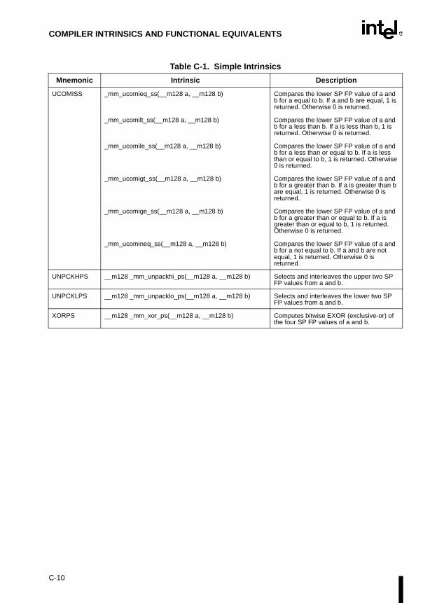
COMPILER INTRINSICS AND FUNCTIONAL EQUIVALENTS
UCOMISS _mm_ucomieq_ss(__m128 a, __m128 b) Compares the lower SP FP value of a and b for a equal to b. If a and b are equal, 1 is returned. Otherwise 0 is returned.
_mm_ucomilt_ss(__m128 a, __m128 b) Compares the lower SP FP value of a and b for a less than b. If a is less than b, 1 is returned. Otherwise 0 is returned.
_mm_ucomile_ss(__m128 a, __m128 b) Compares the lower SP FP value of a and b for a less than or equal to b. If a is less than or equal to b, 1 is returned. Otherwise 0 is returned.
_mm_ucomigt_ss(__m128 a, __m128 b) Compares the lower SP FP value of a and b for a greater than b. If a is greater than b are equal, 1 is returned. Otherwise 0 is returned.
_mm_ucomige_ss(__m128 a, __m128 b) Compares the lower SP FP value of a and b for a greater than or equal to b. If a is greater than or equal to b, 1 is returned. Otherwise 0 is returned.
_mm_ucomineq_ss(__m128 a, __m128 b) Compares the lower SP FP value of a and b for a not equal to b. If a and b are not equal, 1 is returned. Otherwise 0 is returned.
UNPCKHPS __m128 _mm_unpackhi_ps(__m128 a, __m128 b) Selects and interleaves the upper two SP FP values from a and b.
UNPCKLPS __m128 _mm_unpacklo_ps(__m128 a, __m128 b) Selects and interleaves the lower two SP FP values from a and b.
XORPS __m128 _mm_xor_ps(__m128 a, __m128 b) Computes bitwise EXOR (exclusive-or) of the four SP FP values of a and b.
Table C-1. Simple Intrinsics
Mnemonic Intrinsic Description
C-10

COMPILER INTRINSICS AND FUNCTIONAL EQUIVALENTS
C.2. COMPOSITE INTRINSICS
Table C-2. Composite Intrinsics
Mnemonic Intrinsic Description
(composite) __m128 _mm_set_ps1(float w)__m128_set1_ps(float w)
Sets the four SP FP values to w.
(composite) __m128 _mm_set_ps(float z, float y, float x, float w) Sets the four SP FP values to the four inputs.
(composite) __m128 _mm_setr_ps(float z, float y, float x, float w) Sets the four SP FP values to the four inputs in reverse order.
(composite) __m128 _mm_setzero_ps(void) Clears the four SP FP values.
MOVSS + shuffle
__m128 _mm_load_ps1(float * p)__m128 _mm_load1_ps(float *p)
Loads a single SP FP value, copying it into all four words.
MOVAPS + shuffle
__m128 _mm_loadr_ps(float * p) Loads four SP FP values in reverse order. The address must be 16-byte-aligned.
MOVSS + shuffle
void _mm_store_ps1(float * p, __m128 a)void _mm_store1_ps(float *p, __m128 a)
Stores the lower SP FP value across four words.
MOVAPS + shuffle
_mm_storer_ps(float * p, __m128 a) Stores four SP FP values in reverse order. The address must be 16-byte-aligned.
C-11

COMPILER INTRINSICS AND FUNCTIONAL EQUIVALENTS
C-12

Index


INDEX
Numerics36-bit Page Size Extension flag, CPUID instruction
. . . . . . . . . . . . . . . . . . . . . . . . . . . .3-115
AAAA instruction. . . . . . . . . . . . . . . . . . . . . . . . .3-17AAD instruction . . . . . . . . . . . . . . . . . . . . . . . .3-18AAM instruction . . . . . . . . . . . . . . . . . . 3-19, 3-682AAS instruction. . . . . . . . . . . . . . . . . . . 3-20, 3-686Abbreviations, opcode key . . . . . . . . . . . . . . . . A-1Access rights, segment descriptor . . . . . . . . .3-342ADC instruction . . . . . . . . . . . . . . . . . . 3-21, 3-367ADD instruction . . . . . . . 3-21, 3-23, 3-143, 3-367ADDPS instruction . . . . . . . . . . . . . . . . . . . . . .3-25Address size attribute override prefix. . . . . . . . .2-2Address size override prefix. . . . . . . . . . . . . . . .2-2Addressing methods
codes . . . . . . . . . . . . . . . . . . . . . . . . . . . . . A-1operand codes . . . . . . . . . . . . . . . . . . . . . . A-3register codes . . . . . . . . . . . . . . . . . . . . . . . A-3
Addressing, segments . . . . . . . . . . . . . . . . . . . .1-7ADDSS instruction . . . . . . . . . . . . . . . . . . . . . .3-27Advanced Programmable Interrupt Controller
(see APIC)AND instruction . . . . . . . . . . . . . . . . . . 3-30, 3-367ANDNPS instruction. . . . . . . . . . . . . . . . . . . . .3-32ANDPS instruction . . . . . . . . . . . . . . . . . . . . . .3-34APIC CPUID instruction flag . . . . . . . . . . . . .3-114Arctangent, FPU operation. . . . . . . . . . . . . . .3-221ARPL instruction . . . . . . . . . . . . . . . . . . . . . . .3-36
BB (default stack size) flag, segment descriptor
. . . . . . . . . . . . . . . . . . . . . . 3-532, 3-582Base (operand addressing) . . . . . . . . . . . . . . . .2-3BCD integers
packed . . . . . . . . . 3-143, 3-145, 3-169, 3-171unpacked 3-17, 3-18, 3-19, 3-20, 3-682, 3-686
Binary numbers . . . . . . . . . . . . . . . . . . . . . . . . .1-7Binary-coded decimal (see BCD)Bit order . . . . . . . . . . . . . . . . . . . . . . . . . . . . . . .1-5BOUND instruction. . . . . . . . . . . . . . . . . . . . . .3-38BOUND range exceeded exception (#BR). . . .3-38BSF instruction. . . . . . . . . . . . . . . . . . . . . . . . .3-40BSR instruction . . . . . . . . . . . . . . . . . . . . . . . .3-42BSWAP instruction. . . . . . . . . . . . . . . . . . . . . .3-44BT instruction . . . . . . . . . . . . . . . . . . . . . . . . . .3-45BTC instruction. . . . . . . . . . . . . . . . . . . 3-47, 3-367BTR instruction. . . . . . . . . . . . . . . . . . . 3-49, 3-367BTS instruction. . . . . . . . . . . . . . . . . . . 3-51, 3-367Byte order. . . . . . . . . . . . . . . . . . . . . . . . . . . . . .1-5
CCaches, invalidating (flushing) . . . . . .3-318, 3-709Call gate . . . . . . . . . . . . . . . . . . . . . . . . . . . . 3-337CALL instruction . . . . . . . . . . . . . . . . . . . . . . . 3-53Calls (see Procedure calls)CBW instruction . . . . . . . . . . . . . . . . . . . . . . . 3-64CDQ instruction . . . . . . . . . . . . . . . . . . . . . . . 3-65CF (carry) flag, EFLAGS register 3-21, 3-23, 3-45,
. . . 3-47, 3-49, 3-51, 3-66, 3-71, 3-146,
. . . . 3-296, 3-301, 3-449, 3-593, 3-628,
. . . . . . . . . . 3-641, 3-644, 3-663, 3-674Classify floating-point value, FPU operation. 3-271CLC instruction . . . . . . . . . . . . . . . . . . . . . . . . 3-66CLD instruction . . . . . . . . . . . . . . . . . . . . . . . . 3-67CLI instruction. . . . . . . . . . . . . . . . . . . . . . . . . 3-68CLTS instruction . . . . . . . . . . . . . . . . . . . . . . . 3-70CMC instruction . . . . . . . . . . . . . . . . . . . . . . . 3-71CMOV flag, CPUID instruction . . . . . . . . . . . 3-115CMOVcc instruction . . . . . . . . . . . . . . . . . . . . 3-72CMOVcc instructions . . . . . . . . . . . . . .3-72, 3-115CMP instruction . . . . . . . . . . . . . . . . . . . . . . . 3-76CMPPS instruction . . . . . . . . . . . . . . . . . . . . . 3-78CMPS instruction . . . . . . . . . . . . . . . . .3-87, 3-606CMPSB instruction . . . . . . . . . . . . . . . . . . . . . 3-87CMPSD instruction . . . . . . . . . . . . . . . . . . . . . 3-87CMPSS instruction . . . . . . . . . . . . . . . . . . . . . 3-90CMPSW instruction . . . . . . . . . . . . . . . . . . . . 3-87CMPXCHG instruction . . . . . . . . . . . .3-100, 3-367CMPXCHG8B instruction . . . . . . . . . . . . . . . 3-102COMISS instruction . . . . . . . . . . . . . . . . . . . 3-104Compatibility, software . . . . . . . . . . . . . . . . . . . 1-6Compiler functional equivalents . . . . . . . . . . 1, C-1Compiler intrinsics . . . . . . . . . . . . . . . . . . . . 1, C-1
composite . . . . . . . . . . . . . . . . . . . . . . . . . C-11simple . . . . . . . . . . . . . . . . . . . . . . . . . . . . . C-2
Condition code flags, EFLAGS register . . . . . 3-72Condition code flags, FPU status word
flags affected by instructions. . . . . . . . . . . 3-12setting . . . . . . . . . . . . . . . . 3-265, 3-267, 3-271
Conditional jump. . . . . . . . . . . . . . . . . . . . . . 3-329Conditional Move and Compare flag, CPUID instruction
. . . . . . . . . . . . . . . . . . . . . . . . . . . 3-115Conforming code segment . . . . . . . . .3-337, 3-342Constants (floating point) loading . . . . . . . . . 3-210Control registers, moving values to and from 3-408Cosine, FPU operation . . . . . . . . . . . .3-186, 3-242CPL. . . . . . . . . . . . . . . . . . . . . . . . . . . .3-68, 3-705CPUID instruction . . . . . . . . . . . . . . . . . . . . . 3-111CPUID instruction flags . . . . . . . . . . . . . . . . 3-114CR0 control register . . . . . . . . . . . . . . . . . . . 3-655CS register . . . . . . . . . .3-53, 3-306, 3-321, 3-333,
. . . . . . . . . . . . . . . . . . . . . .3-403, 3-532CS segment override prefix . . . . . . . . . . . . . . . 2-2
INDEX-1

INDEX
Current privilege level (see CPL)CVTPI2PS instruction . . . . . . . . . . . . . . . . . .3-119CVTPS2PI instruction . . . . . . . . . . . . . . . . . .3-123CVTSI2SS instruction . . . . . . . . . . . . . . . . . .3-127CVTSS2SI instruction . . . . . . . . . . . . . . . . . .3-130CVTTPS2PI instruction . . . . . . . . . . . . . . . . .3-133CVTTSS2SI instruction . . . . . . . . . . . . . . . . .3-137CWD instruction . . . . . . . . . . . . . . . . . . . . . . .3-141CWDE instruction (see CBW instruction)CX8 flag, CPUID instruction. . . . . . . . . . . . . .3-114
DD (default operation size) flag, segment descriptor
. . . . . . . . . . . . . . . . 3-532, 3-537, 3-582DAA instruction . . . . . . . . . . . . . . . . . . . . . . .3-143DAS instruction . . . . . . . . . . . . . . . . . . . . . . .3-145DE flag, CPUID instruction. . . . . . . . . . . . . . .3-114Debug registers, moving value to and from . .3-410Debugging Extensions flag, CPUID instruction
. . . . . . . . . . . . . . . . . . . . . . . . . . . .3-114DEC instruction . . . . . . . . . . . . . . . . . 3-146, 3-367Denormal number(see Denormalized finite number)Denormalized finite number . . . . . . . . . . . . . .3-271DF (direction) flag, EFLAGS register . . 3-67, 3-88,
. . . . . . . . . . . . . . . .3-303, 3-369, 3-436,
. . . . . . . . . . . . . . . . 3-466, 3-630, 3-664Displacement (operand addressing) . . . . . . . . .2-3DIV instruction . . . . . . . . . . . . . . . . . . . . . . . .3-148Divide error exception (#DE) . . . . . . . . . . . . .3-148DIVPS instruction . . . . . . . . . . . . . . . . . . . . . .3-151DIVSS instruction . . . . . . . . . . . . . . . . . . . . . .3-154DS register . . . . .3-87, 3-349, 3-369, 3-436, 3-466DS segment override prefix . . . . . . . . . . . . . . . .2-2
EEDI register . . . . . . . . . 3-87, 3-630, 3-664, 3-669Effective address . . . . . . . . . . . . . . . . . . . . . .3-353EFLAGS register
condition codes. . . . . . . . . . 3-73, 3-178, 3-183flags affected by instructions . . . . . . . . . . .3-11loading . . . . . . . . . . . . . . . . . . . . . . . . . . .3-341popping . . . . . . . . . . . . . . . . . . . . . . . . . . .3-539popping on return from interrupt . . . . . . . .3-321pushing . . . . . . . . . . . . . . . . . . . . . . . . . . .3-588pushing on interrupts . . . . . . . . . . . . . . . .3-306saving . . . . . . . . . . . . . . . . . . . . . . . . . . . .3-622status flags . . . . . . . 3-76, 3-330, 3-633, 3-689
EIP register . . . . . . . . . 3-53, 3-306, 3-321, 3-333EMMS instruction . . . . . . . . . . . . . . . . . . . . . .3-156Encoding
floating-point instruction formats. . . . . . . . B-36formats and encodings . . . . . . . . . . . . . . . B-27granularity field . . . . . . . . . . . . . . . . . . . . . B-19instruction prefixes . . . . . . . . . . . . . . . . . . B-24instruction prefixes, cacheability control
instruction behavior . . . . . . . . . . . . . . . B-25
integer instruction . . . . . . . . . . . . . . . . . . . . B-6MMX instructions. . . . . . . . . . . . . . . . . . . . B-19MMX instructions, general-purpose register fields
. . . . . . . . . . . . . . . . . . . . . . . . . . . . . . . B-19notations . . . . . . . . . . . . . . . . . . . . . . . . . . B-26Pentium III processor extensions cacheability
control register field . . . . . . . . . . . . . . . B-35SIMD floating-point register field . . . . . . . . B-27SIMD integer instruction behavior . . . . . . . B-25SIMD-integer register field . . . . . . . . . . . . B-34Streaming SIMD Extension formats and
encodings table . . . . . . . . . . . . . . . . . . B-24ENTER instruction . . . . . . . . . . . . . . . . . . . . 3-158ES register . . . . 3-87, 3-349, 3-466, 3-630, 3-669ES segment override prefix . . . . . . . . . . . . . . . 2-2ESI register. . . . 3-87, 3-369, 3-436, 3-466, 3-664ESP register . . . . . . . . . . . . . . . . . . . . .3-54, 3-533Exceptions
BOUND range exceeded (#BR) . . . . . . . . 3-38list . . . . . . . . . . . . . . . . . . . . . . . . . . . . . . . 3-13notation . . . . . . . . . . . . . . . . . . . . . . . . . . . . 1-8overflow exception (#OF) . . . . . . . . . . . . 3-306returning from . . . . . . . . . . . . . . . . . . . . . 3-321
Exponentextracting from floating-point number . . . 3-285
Extract exponent and significand, FPU operation. . . . . . . . . . . . . . . . . . . . . . . . . . . 3-285
FF2XM1 instruction. . . . . . . . . . . . . . . .3-161, 3-285FABS instruction. . . . . . . . . . . . . . . . . . . . . . 3-163FADD instruction . . . . . . . . . . . . . . . . . . . . . 3-165FADDP instruction . . . . . . . . . . . . . . . . . . . . 3-165Far call, CALL instruction . . . . . . . . . . . . . . . . 3-53Far pointer, loading. . . . . . . . . . . . . . . . . . . . 3-349Far return, RET instruction . . . . . . . . . . . . . . 3-609Fast FP/MMXtm Technology/Streaming SIMD
Extensions save/restore flag, CPUID instruction. . . . . . . . . . . . . . . . . . . . . . . . . . . 3-115
Fast System Call flag, CPUID instruction . . . 3-115FBLD instruction . . . . . . . . . . . . . . . . . . . . . . 3-169FBSTP instruction. . . . . . . . . . . . . . . . . . . . . 3-171FCHS instruction . . . . . . . . . . . . . . . . . . . . . 3-174FCLEX instruction. . . . . . . . . . . . . . . . . . . . . 3-176FCMOVcc instructions . . . . . . . . . . . .3-115, 3-178FCOM instruction . . . . . . . . . . . . . . . . . . . . . 3-180FCOMI instruction. . . . . . . . . . . . . . . .3-115, 3-183FCOMIP instruction . . . . . . . . . . . . . . . . . . . 3-183FCOMP instruction . . . . . . . . . . . . . . . . . . . . 3-180FCOMPP instruction. . . . . . . . . . . . . . . . . . . 3-180FCOS instruction . . . . . . . . . . . . . . . . . . . . . 3-186FDECSTP instruction . . . . . . . . . . . . . . . . . . 3-188FDIV instruction . . . . . . . . . . . . . . . . . . . . . . 3-189FDIVP instruction . . . . . . . . . . . . . . . . . . . . . 3-189FDIVR instruction . . . . . . . . . . . . . . . . . . . . . 3-193FDIVRP instruction . . . . . . . . . . . . . . . . . . . . 3-193Feature information, processor. . . . . . . . . . . 3-111
INDEX-2

INDEX
FFREE instruction . . . . . . . . . . . . . . . . . . . . .3-197FIADD instruction . . . . . . . . . . . . . . . . . . . . . .3-165FICOM instruction . . . . . . . . . . . . . . . . . . . . .3-198FICOMP instruction . . . . . . . . . . . . . . . . . . . .3-198FIDIV instruction. . . . . . . . . . . . . . . . . . . . . . .3-189FIDIVR instruction . . . . . . . . . . . . . . . . . . . . .3-193FILD instruction . . . . . . . . . . . . . . . . . . . . . . .3-200FIMUL instruction . . . . . . . . . . . . . . . . . . . . . .3-216FINCSTP instruction . . . . . . . . . . . . . . . . . . .3-202FINIT instruction. . . . . . . . . . . . . . . . . 3-203, 3-235FIST instruction . . . . . . . . . . . . . . . . . . . . . . .3-205FISTP instruction . . . . . . . . . . . . . . . . . . . . . .3-205FISUB instruction . . . . . . . . . . . . . . . . . . . . . .3-257FISUBR instruction. . . . . . . . . . . . . . . . . . . . .3-261FLD instruction . . . . . . . . . . . . . . . . . . . . . . . .3-208FLD1 instruction . . . . . . . . . . . . . . . . . . . . . . .3-210FLDCW instruction . . . . . . . . . . . . . . . . . . . . .3-212FLDENV instruction . . . . . . . . . . . . . . . . . . . .3-214FLDL2E instruction. . . . . . . . . . . . . . . . . . . . .3-210FLDL2T instruction. . . . . . . . . . . . . . . . . . . . .3-210FLDLG2 instruction . . . . . . . . . . . . . . . . . . . .3-210FLDLN2 instruction . . . . . . . . . . . . . . . . . . . .3-210FLDPI instruction . . . . . . . . . . . . . . . . . . . . . .3-210FLDZ instruction. . . . . . . . . . . . . . . . . . . . . . .3-210Floating-point exceptions . . . . . . . . . . . . . . . . .3-14
list, including mnemonics . . . . . . . . . . . . . .3-14Streaming SIMD Extensions. . . . . . . . . . . .3-14
Flushingcaches . . . . . . . . . . . . . . . . . . . . . 3-318, 3-709TLB entry . . . . . . . . . . . . . . . . . . . . . . . . .3-320
FMUL instruction . . . . . . . . . . . . . . . . . . . . . .3-216FMULP instruction . . . . . . . . . . . . . . . . . . . . .3-216FNCLEX instruction . . . . . . . . . . . . . . . . . . . .3-176FNINIT instruction . . . . . . . . . . . . . . . . . . . . .3-203FNOP instruction . . . . . . . . . . . . . . . . . . . . . .3-220FNSAVE instruction . . . . . . . . . . . . . . 3-232, 3-235FNSTCW instruction . . . . . . . . . . . . . . . . . . .3-249FNSTENV instruction . . . . . . . . . . . . . 3-214, 3-251FNSTSW instruction. . . . . . . . . . . . . . . . . . . .3-254Formats (see Encodings)FPATAN instruction . . . . . . . . . . . . . . . . . . . .3-221FPREM instruction . . . . . . . . . . . . . . . . . . . . .3-223FPREM1 instruction . . . . . . . . . . . . . . . . . . . .3-226FPTAN instruction . . . . . . . . . . . . . . . . . . . . .3-229FPU
checking for pending FPU exceptions . . .3-708constants . . . . . . . . . . . . . . . . . . . . . . . . .3-210existence of. . . . . . . . . . . . . . . . . . . . . . . .3-114initialization . . . . . . . . . . . . . . . . . . . . . . . .3-203
FPU control wordloading . . . . . . . . . . . . . . . . . . . . . 3-212, 3-214RC field . . . . . . . . . . . . . . . 3-206, 3-210, 3-246restoring . . . . . . . . . . . . . . . . . . . . . . . . . .3-232saving . . . . . . . . . . . . . . . . . . . . . . 3-235, 3-251storing . . . . . . . . . . . . . . . . . . . . . . . . . . . .3-249
FPU data pointer . . . . 3-214, 3-232, 3-235, 3-251FPU flag, CPUID instruction. . . . . . . . . . . . . .3-114FPU instruction pointer 3-214, 3-232, 3-235, 3-251
FPU last opcode . . . . . 3-214, 3-232, 3-235, 3-251FPU status word
condition code flags . . . . . . . . . . 3-180, 3-198, . . . . . . . . . . . . . . . . . . . 3-265, 3-267, 3-271
FPU flags affected by instructions. . . . . . . 3-12loading. . . . . . . . . . . . . . . . . . . . . . . . . . . 3-214restoring . . . . . . . . . . . . . . . . . . . . . . . . . 3-232saving . . . . . . . . . . . . . . . . 3-235, 3-251, 3-254TOP field . . . . . . . . . . . . . . . . . . . . . . . . . 3-202
FPU tag word . . . . . . . 3-214, 3-232, 3-235, 3-251FRNDINT instruction . . . . . . . . . . . . . . . . . . 3-231FRSTOR instruction . . . . . . . . . . . . . . . . . . . 3-232FS register . . . . . . . . . . . . . . . . . . . . . . . . . . 3-349FS segment override prefix . . . . . . . . . . . . . . . 2-2FSAVE instruction . . . . . . . . . . . . . . .3-232, 3-235FSCALE instruction . . . . . . . . . . . . . . . . . . . 3-238FSIN instruction . . . . . . . . . . . . . . . . . . . . . . 3-240FSINCOS instruction . . . . . . . . . . . . . . . . . . 3-242FSQRT instruction . . . . . . . . . . . . . . . . . . . . 3-244FST instruction . . . . . . . . . . . . . . . . . . . . . . . 3-246FSTCW instruction . . . . . . . . . . . . . . . . . . . . 3-249FSTENV instruction . . . . . . . . . . . . . . . . . . . 3-251FSTP instruction . . . . . . . . . . . . . . . . . . . . . . 3-246FSTSW instruction . . . . . . . . . . . . . . . . . . . . 3-254FSUB instruction. . . . . . . . . . . . . . . . . . . . . . 3-257FSUBP instruction . . . . . . . . . . . . . . . . . . . . 3-257FSUBR instruction . . . . . . . . . . . . . . . . . . . . 3-261FSUBRP instruction . . . . . . . . . . . . . . . . . . . 3-261FTST instruction . . . . . . . . . . . . . . . . . . . . . . 3-265FUCOM instruction . . . . . . . . . . . . . . . . . . . . 3-267FUCOMI instruction . . . . . . . . . . . . . . . . . . . 3-183FUCOMIP instruction . . . . . . . . . . . . . . . . . . 3-183FUCOMP instruction. . . . . . . . . . . . . . . . . . . 3-267FUCOMPP instruction . . . . . . . . . . . . . . . . . 3-267FWAIT instruction . . . . . . . . . . . . . . . .3-270, 3-708FXAM instruction . . . . . . . . . . . . . . . . . . . . . 3-271FXCH instruction . . . . . . . . . . . . . . . . . . . . . 3-273FXRSTOR instruction . . . . . . . . . . . . . . . . . . 3-275FXSAVE instruction . . . . . . . . . . . . . . . . . . . 3-279FXSR flag, CPUID instruction. . . . . . . . . . . . 3-115FXTRACT instruction . . . . . . . . . . . . .3-238, 3-285FYL2X instruction . . . . . . . . . . . . . . . . . . . . . 3-287FYL2XP1 instruction. . . . . . . . . . . . . . . . . . . 3-289
GGDT (global descriptor table) . . . . . . .3-359, 3-362GDTR (global descriptor table register) . . . . 3-359,
. . . . . . . . . . . . . . . . . . . . . . . . . . . 3-637General-purpose registers
MMX registers . . . . . . . . . . . . . . . . . . . . . . B-19moving value to and from . . . . . . . . . . . . 3-403popping all . . . . . . . . . . . . . . . . . . . . . . . . 3-537pushing all . . . . . . . . . . . . . . . . . . . . . . . . 3-585
GS register . . . . . . . . . . . . . . . . . . . . . . . . . . 3-349GS segment override prefix . . . . . . . . . . . . . . . 2-2
INDEX-3

INDEX
HHexadecimal numbers . . . . . . . . . . . . . . . . . . . .1-7HLT instruction . . . . . . . . . . . . . . . . . . . . . . . .3-291
IIDIV instruction. . . . . . . . . . . . . . . . . . . . . . . .3-292IDT (interrupt descriptor table) . . . . . . 3-307, 3-359IDTR (interrupt descriptor table register) . . . 3-359,
. . . . . . . . . . . . . . . . . . . . . . . . . . . .3-637IF (interrupt enable) flag, EFLAGS register . . 3-68,
. . . . . . . . . . . . . . . . . . . . . . . . . . . .3-665Immediate operands . . . . . . . . . . . . . . . . . . . . .2-3IMUL instruction . . . . . . . . . . . . . . . . . . . . . . .3-295IN instruction . . . . . . . . . . . . . . . . . . . . . . . . .3-299INC instruction . . . . . . . . . . . . . . . . . . 3-301, 3-367Index (operand addressing) . . . . . . . . . . . . . . . .2-3Initialization FPU . . . . . . . . . . . . . . . . . . . . . .3-203Input/output (see I/O)INS instruction . . . . . . . . . . . . . . . . . . 3-303, 3-606INSB instruction . . . . . . . . . . . . . . . . . . . . . . .3-303INSD instruction . . . . . . . . . . . . . . . . . . . . . . .3-303Instruction format
base field . . . . . . . . . . . . . . . . . . . . . . . . . . .2-3description of reference information . . . . . . .3-1displacement. . . . . . . . . . . . . . . . . . . . . . . . .2-3illustration . . . . . . . . . . . . . . . . . . . . . . . . . . .2-1immediate . . . . . . . . . . . . . . . . . . . . . . . . . . .2-3index field . . . . . . . . . . . . . . . . . . . . . . . . . . .2-3Mod field . . . . . . . . . . . . . . . . . . . . . . . . . . . .2-2ModR/M byte . . . . . . . . . . . . . . . . . . . . . . . .2-2opcode . . . . . . . . . . . . . . . . . . . . . . . . . . . . .2-2prefixes . . . . . . . . . . . . . . . . . . . . . . . . . . . . .2-1reg/opcode field . . . . . . . . . . . . . . . . . . . . . .2-2r/m field . . . . . . . . . . . . . . . . . . . . . . . . . . . . .2-2scale field . . . . . . . . . . . . . . . . . . . . . . . . . . .2-3SIB byte . . . . . . . . . . . . . . . . . . . . . . . . . . . .2-2
Instruction formats and encodings . . . . . . . . . . B-1Instruction operands. . . . . . . . . . . . . . . . . . . . . .1-7Instruction prefixes (see Prefixes)Instruction reference, nomenclature. . . . . . . . . .3-1Instruction set
reference. . . . . . . . . . . . . . . . . . . . . . . . . . . .3-1string instructions . . . . . . . .3-87, 3-303, 3-369,
. . . . . . . . . . . . . . . . . . 3-436, 3-466, 3-669INSW instruction . . . . . . . . . . . . . . . . . . . . . .3-303INT 3 instruction . . . . . . . . . . . . . . . . . . . . . . .3-306INT3 instruction . . . . . . . . . . . . . . . . . . . . . . .3-306Integer instruction
encodings . . . . . . . . . . . . . . . . . . . . . . . . . . B-6formats . . . . . . . . . . . . . . . . . . . . . . . . . . . . B-6
Integer storing, FPU data type . . . . . . . . . . . .3-205Inter-privilege level call, CALL instruction . . . .3-53Inter-privilege level return, RET instruction . .3-609Interrupts
interrupt vector 4. . . . . . . . . . . . . . . . . . . .3-306returning from . . . . . . . . . . . . . . . . . . . . . .3-321software . . . . . . . . . . . . . . . . . . . . . . . . . .3-306
INDEX-4
INTn instruction . . . . . . . . . . . . . . . . . . . . . . 3-306INTO instruction . . . . . . . . . . . . . . . . . . . . . . 3-306Intrinsics . . . . . . . . . . . . . . . . . . . . . . . . . . . . . . C-1INVD instruction . . . . . . . . . . . . . . . . . . . . . . 3-318INVLPG instruction . . . . . . . . . . . . . . . . . . . . 3-320IOPL (I/O privilege level) field, EFLAGS register .
3-68, 3-588, 3-665IRET instruction . . . . . . . . . . . . . . . . . . . . . . 3-321IRETD instruction . . . . . . . . . . . . . . . . . . . . . 3-321I/O privilege level (see IOPL)
JJcc instructions . . . . . . . . . . . . . . . . . . . . . . . 3-329JMP instruction . . . . . . . . . . . . . . . . . . . . . . . 3-333Jump operation. . . . . . . . . . . . . . . . . . . . . . . 3-333
LLAHF instruction . . . . . . . . . . . . . . . . . . . . . . 3-341LAR instruction . . . . . . . . . . . . . . . . . . . . . . . 3-342LDMXCSR instruction. . . . . . . . . . . . . . . . . . 3-345LDS instruction . . . . . . . . . . . . . . . . . . . . . . . 3-349LDT (local descriptor table) . . . . . . . . . . . . . 3-362LDTR (local descriptor table register).3-362, 3-653LEA instruction . . . . . . . . . . . . . . . . . . . . . . . 3-353LEAVE instruction. . . . . . . . . . . . . . . . . . . . . 3-355LES instruction . . . . . . . . . . . . . . . . . .3-349, 3-357LFS instruction . . . . . . . . . . . . . . . . . .3-349, 3-358LGDT instruction. . . . . . . . . . . . . . . . . . . . . . 3-359LGS instruction . . . . . . . . . . . . . . . . . .3-349, 3-361LIDT instruction . . . . . . . . . . . . . . . . .3-359, 3-364LLDT instruction . . . . . . . . . . . . . . . . . . . . . . 3-362LMSW instruction . . . . . . . . . . . . . . . . . . . . . 3-365Load effective address operation . . . . . . . . . 3-353LOCK prefix2-1, 3-100, 3-102, 3-367, 3-713, 3-715Locking operation . . . . . . . . . . . . . . . . . . . . . 3-367LODS instruction . . . . . . . . . . . . . . . .3-369, 3-606LODSB instruction . . . . . . . . . . . . . . . . . . . . 3-369LODSD instruction . . . . . . . . . . . . . . . . . . . . 3-369LODSW instruction . . . . . . . . . . . . . . . . . . . . 3-369Log epsilon, FPU operation . . . . . . . . . . . . . 3-287Log (base 2), FPU operation . . . . . . . . . . . . 3-289LOOP instruction . . . . . . . . . . . . . . . . . . . . . 3-372LOOPcc instructions. . . . . . . . . . . . . . . . . . . 3-372LSL instruction . . . . . . . . . . . . . . . . . . . . . . . 3-375LSS instruction . . . . . . . . . . . . . . . . . .3-349, 3-379LTR instruction . . . . . . . . . . . . . . . . . . . . . . . 3-380
MMachine Check Architecture flag, CPUID instruction
. . . . . . . . . . . . . . . . . . . . . . . . . . . 3-115Machine Check Exception) flag, CPUID instruction
. . . . . . . . . . . . . . . . . . . . . . . . . . . 3-114Machine instruction encoding and format
condition test field . . . . . . . . . . . . . . . . . . . . B-5direction bit . . . . . . . . . . . . . . . . . . . . . . . . . B-5

INDEX
operand size bit . . . . . . . . . . . . . . . . . . . . . B-3reg field . . . . . . . . . . . . . . . . . . . . . . . . . . . . B-2segment register field . . . . . . . . . . . . . . . . . B-4sign extend bit. . . . . . . . . . . . . . . . . . . . . . . B-3
Machine status word, CR0 register . . 3-365, 3-655MASKMOVQ instruction. . . . . . . . . . . . . . . . .3-382MAXPS instruction . . . . . . . . . . . . . . . . . . . . .3-387MAXSS instruction . . . . . . . . . . . . . . . . . . . . .3-391MCA flag, CPUID instruction . . . . . . . . . . . . .3-115MCE flag, CPUID instruction . . . . . . . . . . . . .3-114Memory Type Range Registers flag, CPUID instruction
. . . . . . . . . . . . . . . . . . . . . . . . . . . .3-115MINPS instruction . . . . . . . . . . . . . . . . . . . . .3-395MINSS instruction . . . . . . . . . . . . . . . . . . . . .3-399MMX instruction
formats and encodings . . . . . . . . . . . . . . . B-19general-purpose register fields . . . . . . . . . B-19granularity field . . . . . . . . . . . . . . . . . . . . . B-19
MMXtm Technologyflag, CPUID instruction . . . . . . . . . . . . . . .3-115
Mod field, instruction format . . . . . . . . . . . . . . . .2-2ModR/M byte
16-bit addressing forms . . . . . . . . . . . . . . . .2-532-bit addressing forms . . . . . . . . . . . . . . . .2-6description . . . . . . . . . . . . . . . . . . . . . . . . . .2-2format . . . . . . . . . . . . . . . . . . . . . . . . . . . . . .2-1
MOV instruction . . . . . . . . . . . . . . . . . . . . . . .3-403control registers . . . . . . . . . . . . . . . . . . . .3-408debug registers . . . . . . . . . . . . . . . . . . . . .3-410
MOVAPS instruction . . . . . . . . . . . . . . . . . . .3-412MOVD instruction . . . . . . . . . . . . . . . . . . . . . .3-415MOVHLPS instruction . . . . . . . . . . . . . . . . . .3-418MOVHPS instruction . . . . . . . . . . . . . . . . . . .3-420MOVLHPS instruction . . . . . . . . . . . . . . . . . .3-423MOVLPS instruction. . . . . . . . . . . . . . . . . . . .3-425MOVMSKPS instruction . . . . . . . . . . . . . . . . .3-428MOVNTPS instruction . . . . . . . . . . . . . . . . . .3-430MOVNTQ instruction . . . . . . . . . . . . . . . . . . .3-432MOVQ instruction. . . . . . . . . . . . . . . . . . . . . .3-434MOVS instruction . . . . . . . . . . . . . . . . 3-436, 3-606MOVSB instruction. . . . . . . . . . . . . . . . . . . . .3-436MOVSD instruction. . . . . . . . . . . . . . . . . . . . .3-436MOVSS instruction. . . . . . . . . . . . . . . . . . . . .3-439MOVSW instruction . . . . . . . . . . . . . . . . . . . .3-436MOVSX instruction. . . . . . . . . . . . . . . . . . . . .3-442MOVUPS instruction . . . . . . . . . . . . . . . . . . .3-444MOVZX instruction . . . . . . . . . . . . . . . . . . . . .3-447MSR flag, CPUID instruction . . . . . . . . . . . . .3-114MSRs (model specific registers)
existence of. . . . . . . . . . . . . . . . . . . . . . . .3-114reading . . . . . . . . . . . . . . . . . . . . . . . . . . .3-601writing . . . . . . . . . . . . . . . . . . . . . . . . . . . .3-711
MTRRs flag, CPUID instruction . . . . . . . . . . .3-115MUL instruction . . . . . . . . . . . . . . . . . 3-449, 3-682MULPS instruction . . . . . . . . . . . . . . . . . . . . .3-451MULSS instruction . . . . . . . . . . . . . . . . . . . . .3-453
NNaN
testing for . . . . . . . . . . . . . . . . . . . . . . . . 3-265Near call, CALL instruction . . . . . . . . . . . . . . . 3-53Near return, RET instruction. . . . . . . . . . . . . 3-609NEG instruction . . . . . . . . . . . . . . . . .3-367, 3-455Nonconforming code segment . . . . . . . . . . . 3-337NOP instruction . . . . . . . . . . . . . . . . . . . . . . 3-457NOT instruction. . . . . . . . . . . . . . . . . .3-367, 3-458Notation
bit and byte order . . . . . . . . . . . . . . . . . . . . 1-5exceptions . . . . . . . . . . . . . . . . . . . . . . . . . . 1-8hexadecimal and binary numbers . . . . . . . . 1-7instruction operands . . . . . . . . . . . . . . . . . . 1-7reserved bits . . . . . . . . . . . . . . . . . . . . . . . . 1-6segmented addressing . . . . . . . . . . . . . . . . 1-7
Notational conventions . . . . . . . . . . . . . . . . . . . 1-5NT (nested task) flag, EFLAGS register . . . . 3-321Numeric overflow exception . . . . . . . . . . . . . . 3-14Numeric underflow exception . . . . . . . . . . . . . 3-14
OOF (carry) flag, EFLAGS register . . . . . . . . . 3-296OF (overflow) flag, EFLAGS register . . 3-21, 3-23,
. . . . . . . . . . . . . . . 3-306, 3-449, 3-628,
. . . . . . . . . . . . . . . . 3-641, 3-644, 3-674Opcode
escape instructions . . . . . . . . . . . . . . . . . . A-12format . . . . . . . . . . . . . . . . . . . . . . . . . . . . . 2-2map . . . . . . . . . . . . . . . . . . . . . . . . . . . . . . . A-1
Opcode extensionsdescription. . . . . . . . . . . . . . . . . . . . . . . . . A-10table . . . . . . . . . . . . . . . . . . . . . . . . . . . . . A-11
Opcode integer instructionsone-byte . . . . . . . . . . . . . . . . . . . . . . . . . . . A-4one-byte opcode map . . . . . . . . . . . . . A-6, A-7two-byte. . . . . . . . . . . . . . . . . . . . . . . . . . . . A-5two-byte opcode map . . . . . . . . . . . . . A-8, A-9
Opcode key abbreviations . . . . . . . . . . . . . . . . A-1Operand instruction . . . . . . . . . . . . . . . . . . . . . 1-7Operand-size override prefix . . . . . . . . . . . . . . 2-2OR instruction. . . . . . . . . . . . . . . . . . .3-367, 3-460ORPS instruction . . . . . . . . . . . . . . . . . . . . . 3-462OUT instruction. . . . . . . . . . . . . . . . . . . . . . . 3-464OUTS instruction . . . . . . . . . . . . . . . .3-466, 3-606OUTSB instruction . . . . . . . . . . . . . . . . . . . . 3-466OUTSD instruction . . . . . . . . . . . . . . . . . . . . 3-466OUTSW instruction. . . . . . . . . . . . . . . . . . . . 3-466Overflow exception (#OF). . . . . . . . . . . . . . . 3-306Overflow, FPU exception (see Numeric overflow
exception)
PPACKSSDW instruction . . . . . . . . . . . . . . . . 3-470PACKSSWB instruction . . . . . . . . . . . . . . . . 3-470
INDEX-5

INDEX
PACKUSWB instruction . . . . . . . . . . . . . . . . .3-473PADDB instruction . . . . . . . . . . . . . . . . . . . . .3-476PADDD instruction . . . . . . . . . . . . . . . . . . . . .3-476PADDSB instruction . . . . . . . . . . . . . . . . . . . .3-480PADDSW instruction . . . . . . . . . . . . . . . . . . .3-480PADDUSB instruction . . . . . . . . . . . . . . . . . .3-483PADDUSW instruction . . . . . . . . . . . . . . . . . .3-483PADDW instruction . . . . . . . . . . . . . . . . . . . .3-476PAE flag, CPUID instruction. . . . . . . . . . . . . .3-114Page Attribute Table flag, CPUID instruction .3-115Page Size Extensions) flag, CPUID instruction
. . . . . . . . . . . . . . . . . . . . . . . . . . . .3-114Page-table-entry global flag, CPUID instruction
. . . . . . . . . . . . . . . . . . . . . . . . . . . .3-115PAND instruction . . . . . . . . . . . . . . . . . . . . . .3-486PANDN instruction . . . . . . . . . . . . . . . . . . . . .3-488PAT flag, CPUID instruction. . . . . . . . . . . . . .3-115PAVGB instruction . . . . . . . . . . . . . . . . . . . . .3-490PAVGW instruction . . . . . . . . . . . . . . . . . . . .3-490PCMPEQB instruction . . . . . . . . . . . . . . . . . .3-494PCMPEQD instruction . . . . . . . . . . . . . . . . . .3-494PCMPEQW instruction. . . . . . . . . . . . . . . . . .3-494PCMPGTB instruction . . . . . . . . . . . . . . . . . .3-498PCMPGTD instruction . . . . . . . . . . . . . . . . . .3-498PCMPGTW instruction . . . . . . . . . . . . . . . . . .3-498PE flag, CR0 register . . . . . . . . . . . . . . . . . . .3-365Performance-monitoring counters, reading . .3-603PEXTRW instruction . . . . . . . . . . . . . . . . . . .3-502PGE flag, CPUID instruction . . . . . . . . . . . . .3-115Physical Address Extension flag, CPUID instruction
. . . . . . . . . . . . . . . . . . . . . . . . . . . .3-114PINSRW instruction . . . . . . . . . . . . . . . . . . . .3-504Pi,loading . . . . . . . . . . . . . . . . . . . . . . . . . . . .3-210PMADDWD instruction. . . . . . . . . . . . . . . . . .3-506PMAXSW instruction . . . . . . . . . . . . . . . . . . .3-509PMAXUB instruction. . . . . . . . . . . . . . . . . . . .3-512PMINSW instruction . . . . . . . . . . . . . . . . . . . .3-515PMINUB instruction . . . . . . . . . . . . . . . . . . . .3-518PMOVMSKB instruction . . . . . . . . . . . . . . . . .3-521PMULHUW instruction . . . . . . . . . . . . . . . . . .3-523PMULHW instruction . . . . . . . . . . . . . . . . . . .3-526PMULLW instruction . . . . . . . . . . . . . . . . . . .3-529PN flag, CPUID instruction. . . . . . . . . . . . . . .3-115POP instruction . . . . . . . . . . . . . . . . . . . . . . .3-532POPA instruction . . . . . . . . . . . . . . . . . . . . . .3-537POPAD instruction . . . . . . . . . . . . . . . . . . . . .3-537POPF instruction . . . . . . . . . . . . . . . . . . . . . .3-539POPFD instruction . . . . . . . . . . . . . . . . . . . . .3-539POR instruction . . . . . . . . . . . . . . . . . . . . . . .3-542PREFETCH instruction . . . . . . . . . . . . . . . . .3-544Prefixes
address size override . . . . . . . . . . . . . . . . . .2-2instruction, description . . . . . . . . . . . . . . . . .2-1LOCK . . . . . . . . . . . . . . . . . . . . . . . . 2-1, 3-367operand-size override . . . . . . . . . . . . . . . . . .2-2REP . . . . . . . . . . . . . . . . . . . . . . . . . . . . .3-606REPE . . . . . . . . . . . . . . . . . . . . . . . . . . . .3-606repeat . . . . . . . . . . . . . . . . . . . . . . . . . . . . . .2-1
INDEX-6
REPNE . . . . . . . . . . . . . . . . . . . . . . . . . . 3-606REPNZ . . . . . . . . . . . . . . . . . . . . . . . . . . 3-606REPZ. . . . . . . . . . . . . . . . . . . . . . . . . . . . 3-606segment override . . . . . . . . . . . . . . . . . . . . 2-2
Procedure stack, pushing values on. . . . . . . 3-582Processor Number flag, CPUID instruction . 3-115Protection Enable flag, CR0 register . . . . . . 3-365PSADBW instruction. . . . . . . . . . . . . . . . . . . 3-546PSE flag, CPUID instruction . . . . . . . . . . . . . 3-114PSE-36 flag, CPUID instruction . . . . . . . . . . 3-115PSHUFW instruction. . . . . . . . . . . . . . . . . . . 3-549PSLLD instruction. . . . . . . . . . . . . . . . . . . . . 3-551PSLLQ instruction. . . . . . . . . . . . . . . . . . . . . 3-551PSLLW instruction . . . . . . . . . . . . . . . . . . . . 3-551PSRAD instruction . . . . . . . . . . . . . . . . . . . . 3-556PSRAW instruction . . . . . . . . . . . . . . . . . . . . 3-556PSRLD instruction . . . . . . . . . . . . . . . . . . . . 3-559PSRLQ instruction . . . . . . . . . . . . . . . . . . . . 3-559PSRLW instruction . . . . . . . . . . . . . . . . . . . . 3-559PSUBB instruction . . . . . . . . . . . . . . . . . . . . 3-564PSUBD instruction . . . . . . . . . . . . . . . . . . . . 3-564PSUBSB instruction . . . . . . . . . . . . . . . . . . . 3-568PSUBSW instruction. . . . . . . . . . . . . . . . . . . 3-568PSUBUSB instruction . . . . . . . . . . . . . . . . . . 3-571PSUBUSW instruction . . . . . . . . . . . . . . . . . 3-571PSUBW instruction . . . . . . . . . . . . . . . . . . . . 3-564PUNPCKHBW instruction. . . . . . . . . . . . . . . 3-574PUNPCKHDQ instruction . . . . . . . . . . . . . . . 3-574PUNPCKHWD instruction. . . . . . . . . . . . . . . 3-574PUNPCKLBW instruction . . . . . . . . . . . . . . . 3-578PUNPCKLDQ instruction . . . . . . . . . . . . . . . 3-578PUNPCKLWD instruction . . . . . . . . . . . . . . . 3-578PUSH instruction . . . . . . . . . . . . . . . . . . . . . 3-582PUSHA instruction . . . . . . . . . . . . . . . . . . . . 3-585PUSHAD instruction . . . . . . . . . . . . . . . . . . . 3-585PUSHF instruction . . . . . . . . . . . . . . . . . . . . 3-588PUSHFD instruction . . . . . . . . . . . . . . . . . . . 3-588PXOR instruction . . . . . . . . . . . . . . . . . . . . . 3-590
QQNaN . . . . . . . . . . . . . . . . . . . . . 3-82, 3-91, 3-171Quiet NaN (see QNaN)
RRC (rounding control) field, FPU control word
. . . . . . . . . . . . . . . . 3-206, 3-210, 3-246RCL instruction . . . . . . . . . . . . . . . . . . . . . . . 3-592RCPPS instruction . . . . . . . . . . . . . . . . . . . . 3-597RCPSS instruction . . . . . . . . . . . . . . . . . . . . 3-599RCR instruction . . . . . . . . . . . . . . . . . . . . . . 3-592RDMSR instruction . . . . . . . . . 3-114, 3-601, 3-605RDPMC instruction . . . . . . . . . . . . . . . . . . . . 3-603RDTSC instruction . . . . . . . . . . . . . . .3-114, 3-605Reg/opcode field, instruction format . . . . . . . . . 2-2Related literature . . . . . . . . . . . . . . . . . . . . . . . 1-9

INDEX
Remainder, FPU operation . . . . . . . . 3-223, 3-226REP prefix . . . . . . . . . . . . . . . . . . . . . . 3-88, 3-606REPE prefix . . . . . . . . . . . . . . . . . . . . . 3-88, 3-606REPNE prefix . . . . . . . . . . . . . . . . . . . . 3-88, 3-606REPNZ prefix . . . . . . . . . . . . . . . . . . . . 3-88, 3-606REPZ prefix . . . . . . . . . . . . . . . . . . . . . 3-88, 3-606REP/REPE/REPZ/REPNE/REPNZ prefixes
. . . . . . . . . . . . . . . . . . 2-1, 3-304, 3-467Reserved bits . . . . . . . . . . . . . . . . . . . . . . . . . . .1-6RET instruction. . . . . . . . . . . . . . . . . . . . . . . .3-609ROL instruction . . . . . . . . . . . . . . . . . 3-592, 3-616ROR instruction . . . . . . . . . . . . . . . . . 3-592, 3-616Rotate operation. . . . . . . . . . . . . . . . . . . . . . .3-592Round to integer, FPU operation . . . . . . . . . .3-231RPL field. . . . . . . . . . . . . . . . . . . . . . . . . . . . . .3-36RSM instruction . . . . . . . . . . . . . . . . . . . . . . .3-617RSQRTPS instruction . . . . . . . . . . . . . . . . . .3-618RSQRTSS instruction . . . . . . . . . . . . . . . . . .3-620R/m field, instruction format . . . . . . . . . . . . . . . .2-2
SSAHF instruction . . . . . . . . . . . . . . . . . . . . . .3-622SAL instruction . . . . . . . . . . . . . . . . . . . . . . . .3-623SAR instruction . . . . . . . . . . . . . . . . . . . . . . .3-623SBB instruction. . . . . . . . . . . . . . . . . . 3-367, 3-628Scale (operand addressing) . . . . . . . . . . . . . . . .2-3Scale, FPU operation . . . . . . . . . . . . . . . . . . .3-238SCAS instruction . . . . . . . . . . . . . . . . 3-606, 3-630SCASB instruction . . . . . . . . . . . . . . . . . . . . .3-630SCASD instruction . . . . . . . . . . . . . . . . . . . . .3-630SCASW instruction. . . . . . . . . . . . . . . . . . . . .3-630Segment descriptor, segment limit. . . . . . . . .3-375Segment limit . . . . . . . . . . . . . . . . . . . . . . . . .3-375Segment override prefixes . . . . . . . . . . . . . . . . .2-2Segment registers, moving values to and from
. . . . . . . . . . . . . . . . . . . . . . . . . . . .3-403Segment selector, RPL field. . . . . . . . . . . . . . .3-36Segmented addressing . . . . . . . . . . . . . . . . . . .1-7SEP flag, CPUID instruction. . . . . . . . . . . . . .3-115SETcc instructions . . . . . . . . . . . . . . . . . . . . .3-633SF (sign) flag, EFLAGS register. . . . . . . 3-21, 3-23SFENCE instruction . . . . . . . . . . . . . . . . . . . .3-635SGDT instruction . . . . . . . . . . . . . . . . . . . . . .3-637SHL instruction. . . . . . . . . . . . . . . . . . 3-623, 3-640SHLD instruction . . . . . . . . . . . . . . . . . . . . . .3-641SHR instruction . . . . . . . . . . . . . . . . . 3-623, 3-640SHRD instruction . . . . . . . . . . . . . . . . . . . . . .3-644SHUFPS instruction . . . . . . . . . . . . . . . . . . . .3-647SIB byte
32-bit addressing forms . . . . . . . . . . . . . . . .2-7description . . . . . . . . . . . . . . . . . . . . . . . . . .2-2format . . . . . . . . . . . . . . . . . . . . . . . . . . . . . .2-1
SIDT instruction . . . . . . . . . . . . . . . . . 3-637, 3-652Signaling NaN (see SNaN)Significan, extracting . . . . . . . . . . . . . . . . . . .3-285SIMD floating-point exceptions (See Floating-point
exceptions)Sine, FPU operation. . . . . . . . . . . . . . 3-240, 3-242SLDT instruction. . . . . . . . . . . . . . . . . . . . . . .3-653
SMSW instruction . . . . . . . . . . . . . . . . . . . . . 3-655SNaN . . . . . . . . . . . . . . . . . . . . . . . . . . . . . . . 3-82SQRTPS instruction . . . . . . . . . . . . . . . . . . . 3-657SQRTSS instruction . . . . . . . . . . . . . . . . . . . 3-660Square root, FPU operation . . . . . . . . . . . . . 3-244SS register . . . . . . . . . . . . . . . 3-349, 3-404, 3-533SS segment override prefix . . . . . . . . . . . . . . . 2-2Stack (see Procedure stack)Status flags, EFLAGS register . 3-73, 3-76, 3-178,
. . . . . . . . . . 3-183, 3-330, 3-633, 3-689STC instruction . . . . . . . . . . . . . . . . . . . . . . . 3-663STD instruction . . . . . . . . . . . . . . . . . . . . . . . 3-664STI instruction. . . . . . . . . . . . . . . . . . . . . . . . 3-665STMXCSR instruction. . . . . . . . . . . . . . . . . . 3-667STOS instruction . . . . . . . . . . . . . . . .3-606, 3-669STOSB instruction . . . . . . . . . . . . . . . . . . . . 3-669STOSD instruction . . . . . . . . . . . . . . . . . . . . 3-669STOSW instruction . . . . . . . . . . . . . . . . . . . . 3-669STR instruction . . . . . . . . . . . . . . . . . . . . . . . 3-672Streaming SIMD Extensions
CPUID instruction flag. . . . . . . . . . . . . . . 3-115encoding Pentium III processor extensions
cacheability control register field . . . . . B-35encoding SIMD floating-point register field B-27encoding SIMD-integer register field. . . . . B-34formats and encodings . . . . . . . . . . . . . . . B-27formats and encodings table . . . . . . . . . . . B-24instruction prefixes . . . . . . . . . . . . . B-24, B-25instruction prefixes, cacheability control
instruction behavior . . . . . . . . . . . . . . . B-25notations . . . . . . . . . . . . . . . . . . . . . . . . . . B-26SIMD integer instruction behavior . . . . . . . B-25
String operations . . . . . . . . . . 3-87, 3-303, 3-369,. . . . . . . . . . . . . . . . 3-436, 3-466, 3-669
SUB instruction. . . . . . 3-145, 3-367, 3-674, 3-686SUBPS instruction . . . . . . . . . . . . . . . . . . . . 3-676SUBSS instruction . . . . . . . . . . . . . . . . . . . . 3-679SYSENTER instruction. . . . . . . . . . . . . . . . . 3-682SYSEXIT instruction . . . . . . . . . . . . . . . . . . . 3-686
TTangent, FPU operation . . . . . . . . . . . . . . . . 3-229Task gate . . . . . . . . . . . . . . . . . . . . . . . . . . . 3-338Task register
loading. . . . . . . . . . . . . . . . . . . . . . . . . . . 3-380storing . . . . . . . . . . . . . . . . . . . . . . . . . . . 3-672
Task state segment (see TSS)Task switch
return from nested task, IRET instruction 3-321Task switch, CALL instruction . . . . . . . . . . . . 3-53TEST instruction . . . . . . . . . . . . . . . . . . . . . . 3-689Time Stamp Counter flag, CPUID instruction 3-114Time-stamp counter, reading . . . . . . . . . . . . 3-605TLB entry, invalidating (flushing) . . . . . . . . . 3-320TS (task switched) flag, CR0 register . . . . . . . 3-70TSC flag, CPUID instruction . . . . . . . . . . . . . 3-114TSD flag, CR4 register . . . . . . . . . . . . . . . . . 3-605TSS, relationship to task register . . . . . . . . . 3-672
INDEX-7

UUCOMISS instruction . . . . . . . . . . . . . . . . . . .3-691UD2 instruction. . . . . . . . . . . . . . . . . . . . . . . .3-698Undefined format opcodes . . . . . . . . . . . . . . .3-265Underflow, FPU exception (see Numeric underflow
exception)Unordered values. . . . 3-180, 3-183, 3-265, 3-267UNPCKHPS instruction . . . . . . . . . . . . . . . . .3-699UNPCKLPS instruction . . . . . . . . . . . . . . . . .3-702
VVector (see Interrupt vector)Vector (see INTn instruction)VERR instruction . . . . . . . . . . . . . . . . . . . . . .3-705Version information, processor . . . . . . . . . . .3-111VERW instruction . . . . . . . . . . . . . . . . . . . . . .3-705Virtual 8086 Mode Enhancements flag, CPUID instruction
. . . . . . . . . . . . . . . . . . . . . . . . . . . .3-114Virtual 8086 Mode flag, EFLAGS register . . .3-321VM flag, EFLAGS register . . . . . . . . . . . . . . .3-321VME flag, CPUID instruction . . . . . . . . . . . . .3-114
WWAIT instruction. . . . . . . . . . . . . . . . . . . . . . .3-708WBINVD instruction . . . . . . . . . . . . . . . . . . . .3-709Write-back and invalidate caches . . . . . . . . .3-709WRMSR instruction . . . . . . . . . . . . . . 3-114, 3-711
XXADD instruction . . . . . . . . . . . . . . . . 3-367, 3-713XCHG instruction . . . . . . . . . . . . . . . . 3-367, 3-715XLAT instruction. . . . . . . . . . . . . . . . . . . . . . .3-717XLATB instruction . . . . . . . . . . . . . . . . . . . . .3-717XMM flag, CPUID instruction . . . . . . . . . . . . .3-115XOR instruction . . . . . . . . . . . . . . . . . 3-367, 3-719XORPS instruction . . . . . . . . . . . . . . . . . . . . .3-721
ZZF (zero) flag, EFLAGS register . . . 3-100, 3-102,
. . . 3-342, 3-372, 3-375, 3-606, 3-705