Embed Size (px)
Citation preview

Soft Matter
PAPER Miguel A. Quetzeri-Santiago, David Fernandez Rivas et al .
Impact of a microfluidic jet on a pendant droplet
ISSN 1744-6848
rsc.li/soft-matter-journal
Volume 17
Number 32
28 August 2021
Pages 7423–7598

7466 | Soft Matter, 2021, 17, 7466–7475 This journal is © The Royal Society of Chemistry 2021
Cite this: Soft Matter, 2021,
17, 7466
Impact of a microfluidic jet on a pendant droplet†
Miguel A. Quetzeri-Santiago, *a Ian W. Hunter,b Devaraj van der Meer c andDavid Fernandez Rivas *ab
High speed microfluidic jets can be generated by a thermocavitation process: from the evaporation of the
liquid inside a microfluidic channel, a rapidly expanding bubble is formed and generates a jet through a flow
focusing effect. Here, we study the impact and traversing of such jets on a pendant liquid droplet. Upon
impact, an expanding cavity is created, and, above a critical impact velocity, the jet traverses the entire droplet.
We predict the critical traversing velocity (i) from a simple energy balance and (ii) by comparing the Young–
Laplace and dynamic pressures in the cavity that is created during the impact. We contrast the model
predictions against experiments, in which we vary the liquid properties of the pendant droplet and find good
agreement. In addition, we assess how surfactants and viscoelastic effects influence the critical impact velocity.
Our results increase the knowledge of the jet interaction with materials of well-known physical properties.
1 Introduction
The impact of a solid or liquid object into a deep liquid poolgenerates a cavity with dynamics first described by Worthing-ton in 1908.1 Since then, research has focused on many topics,including the critical energy necessary for air entrainment intoa pool, the collapse of the formed cavity, and the subsequentformation of Worthington jets.2–7 The projectiles studied in theliterature usually have sizes in the range of 1 to 5 mm, animpact speed range of 1 to 10 m s�1, and the pool is usuallyorders of magnitude larger than the projectile and the createdcavity.2–7 In these cases, hydrostatic pressure has been found tobe a major driver for the collapse and retraction of the cavitymade on the liquid pool.2 In contrast, we found just two worksdiscussing the impact of projectiles in the submillimeterrange.8,9 In this paper we study for the first time the impactof micrometer-sized jets (E100 mm) on a self-contained liquidobject, namely droplets of E2 mm. In this case, the jets travellingat speeds of E20 m s�1 generate a cavity circumscribed by thedroplet volume and the hydrostatic pressure can be neglected.
Since the dynamics of the aforementioned events take placein a few milliseconds, high-speed imaging is required toobserve the phenomena. High-speed imaging was pioneeredby scientists like Harold E. Edgerton, using his strobe-flashphotography technique.10 One of his most famous sequences ofpictures is that of a 0.22 inch caliber bullet traversing an appleat E380 m s�1 (Fig. 1a). In this sequence, the apple is opaque,but, what if we could replace the target with a transparentobject, i.e., a liquid apple? This is precisely the case when wetarget a droplet with a liquid microjet. As shown in Fig. 1, theaesthetics of a high-speed jet traversing a liquid droplet andEdgerton’s pictures are strikingly similar. The difference is that,with a translucent liquid, we can observe the impact dynamicsinside the droplet, and besides producing impressive images,high-speed imaging facilitates the description of the fast phe-nomena, such as providing the projectile speed and the targetdeformation.
Our aim in this paper is to unravel the physics that governsthe impact of liquid water jets on a pendant droplet of liquidswith different properties. This knowledge increases our under-standing of the jet interaction with materials of well-knownphysical properties. Such an understanding can advance ourknowledge on needle-free injections, because jets of similarsizes and speeds in the present study have been proposed forthat purpose.11–13
The paper is structured as follows. The experimental proce-dure is outlined in Section 2. In Section 3 we present twomodels to predict the critical jet velocity for traversing adroplet: in Section 3.1 we use an energy balance between thekinetic energy of the jet and the surface energy of the droplet. InSection 3.2, we employ the two-dimensional Rayleigh equation toobtain the cavity shape and combine it with the Young–Laplace
a Mesoscale Chemical Systems Group, MESA+ Institute and Faculty of Science and
Technology, University of Twente, P. O. Box 217, 7500AE Enschede,
The Netherlands. E-mail: [email protected],
[email protected] BioInstrumentation Laboratory, Department of Mechanical Engineering,
Massachusetts Institute of Technology, Cambridge, Massachusetts 02139, USAc Physics of Fluids group and Max Plank Center Twente, Mesa + Institute and
Faculty of Science and Technology, J. M. Burgers Centre for Fluid Dynamics and
Max Plank Center Twente for Complex Fluid Dynamics, University of Twente,
P. O. Box 217, 7500AE Enschede, The Netherlands
† Electronic supplementary information (ESI) available. See DOI: 10.1039/d1sm00706h
Received 12th May 2021,Accepted 25th June 2021
DOI: 10.1039/d1sm00706h
rsc.li/soft-matter-journal
Soft Matter
PAPER
Ope
n A
cces
s A
rtic
le. P
ublis
hed
on 2
8 Ju
ne 2
021.
Dow
nloa
ded
on 2
/8/2
022
11:0
1:01
AM
. T
his
artic
le is
lice
nsed
und
er a
Cre
ativ
e C
omm
ons
Attr
ibut
ion
3.0
Unp
orte
d L
icen
ce.
View Article OnlineView Journal | View Issue

This journal is © The Royal Society of Chemistry 2021 Soft Matter, 2021, 17, 7466–7475 | 7467
equation to predict its collapse. Next, the model prediction iscontrasted against experimental results in Section 4.1. Additionally,in Sections 4.2 and 4.3 we present experimental results on thecavity advancing and retracting velocities with some observationson what occurs after the cavity collapse.
2 Experimental method
High-speed jets were generated via a thermocavitation processand directed to impact a pendant droplet of different liquidswith varying properties. Thermocavitation refers to the pheno-menon in which a liquid is vaporised locally by means of afocused laser, leading to bubble nucleation.14,15 The expansionof the nucleated bubble can be controlled on a microfluidicchip to generate a jet through a flow-focusing effect.16,17 Thesejets may reach speeds of the order of 100 m s�1, which isenough to pierce the skin, and has potential for the transdermaldelivery of a liquid, e.g. needle-free injections.18,19 However, in theexperiments described here, we restrict the jet velocity Ujet to therange of 8–35 m s�1, which is sufficient for a jet to traversedroplets of the liquids studied. Additionally, the diameter Djet ofthe liquid jet was in the range of 50–120 mm. Both Ujet and Djet
were controlled by varying the laser spot size and power.The experimental setup is shown in Fig. 2. A Borofloat glass
microfluidic chip fabricated under cleanroom conditions isfilled with a water solution containing a red dye (Direct Red81, CAS No. 2610-11-9) at 0.5 wt%. The red dye enhances thelaser energy absorption and facilitates bubble nucleation.The microfluidic device has a tapered channel with an anglea = 15 degrees to avoid swirling of the jet,17 nozzle diameterd = 120 mm, channel length L = 1050 mm and width W = 600 mm.The thermocavitation bubble is created by focusing a continuouswave laser diode (Roithner LaserTechnik, wavelength L = 450 nmand nominal power of 3.5 W), on the microchannel using a10� microscope objective. The liquids used were water, ethanol,aqueous solutions of glycerol, Triton X-100 and sodium-bis(2-ethylhexyl)sulfosuccinate (Aerosol OT) at different concentra-tions and polyethylene-oxide of varied molecular weights (PEO).Liquid droplets were created by holding a capillary tube with an
outer diameter of 360 mm, controlling the volume with a precisionglass syringe and a syringe pump (Harvard PHD 22/2000). Allchemical additives were bought from Sigma-Aldrich. The proper-ties of the Newtonian and non-Newtonian liquids used arereported in Table 1. The surface tension of all the liquids wasmeasured with Pendent Drop ImageJ plugin,20 and their shearviscosity was measured with an Anton Paar MCR 502 rheometer.
The processes of bubble generation, jet ejection and impacton the liquid droplet were recorded using a Photron FastcamSAX coupled with a 2� microscope objective. A typical experi-ment duration was B5 ms and the camera resolution was set to768 � 328 pixels2 at a sample rate of 50k frames per secondwith an exposure time of 2.5 ms. Typical images obtained fromthe experiments are shown in Fig. 3, where one can observehow a water droplet is pierced by the liquid jet produced fromthe microchip on the left, using shadowgraph imaging (left)and direct lighting (right). Experiments were carried out with atypical shadowgraph configuration, and we switched to a frontlight illumination system to observe the cavity dynamics. In thefront illumination system a white background was placed toenhance the image contrast and increase the light reaching thecamera sensor. Image analysis to extract the jet diameter, impactvelocity and cavity dynamics was performed with a custom
Fig. 1 Comparison between a sequence of images from, (a) Harold E. Edgerton, Bullet through Apple, 1964, Ubullet B 500 m s�1 (reprinted with thepermission of James W. Bales and Andrew Davidhazy). The sequence is taken using the flash photography technique,10 with a flash duration of E1/3 ms.The flash is triggered by an electronic circuit that reacts to the sound of a rifle shot. (b) The impact of a liquid jet on a droplet; the video is recorded using ahigh-speed camera at 50k frames per second, and the jet diameter is Djet = 100 m and its impact velocity is Ujet = 25.8 m s�1 (see also Movie S1 in theESI†). Apart from the striking aesthetic resemblance of the processes, the ratio between the projectile kinetic energy and the energy associated with thetarget’s resistance to deformation is on the same order of magnitude, see Section 3.1.
Fig. 2 Schematic of the experimental setup. Thermocavitation is obtainedfocusing a CW laser on the bottom of a microfluidic device with amicroscope objective. The thermocavitated bubble expands and createsa liquid jet that is directed at a pendant droplet. The process is recordedwith a high-speed camera with the illumination coming from a light sourcefrom the front so the cavity evolution can be observed.
Paper Soft Matter
Ope
n A
cces
s A
rtic
le. P
ublis
hed
on 2
8 Ju
ne 2
021.
Dow
nloa
ded
on 2
/8/2
022
11:0
1:01
AM
. T
his
artic
le is
lice
nsed
und
er a
Cre
ativ
e C
omm
ons
Attr
ibut
ion
3.0
Unp
orte
d L
icen
ce.
View Article Online

7468 | Soft Matter, 2021, 17, 7466–7475 This journal is © The Royal Society of Chemistry 2021
generated MATLAB script. The shadowgraph imaging benefitsfrom more light reaching the sensor, and thus a smaller cameraexposure time can be used, leading to a better jet definition.However, extracting information from the expanding cavity isimpossible. In contrast, with front light imaging we can extractthe information from the expanding cavity, but the jet is not aswell defined as that using shadowgraphy.
3 Critical jet velocity
In this section, we predict the critical velocity needed for a jet totraverse a droplet using two different approaches: (i) by using asimple energy balance and (ii) by comparing the Young–
Laplace and dynamic pressures in the cavity that is createdduring impact. In Section 3.1, we start from an energy analysisof Edgerton’s experiment of a bullet traversing an apple andsubsequently transfer the argument to the droplet case of ourcurrent study. With this example we introduce the concept ofkinetic energy of the projectile and the resistance of the targetto being traversed. Moreover, we deduce the critical velocity ofthe jet by doing an energy balance between the kinetic energy ofthe jet and the surface energy of the droplet. Additionally, inSection 3.2, we use Rayleigh’s two-dimensional equation topredict the shape of the cavity and predict its collapse withthe Young–Laplace equation, thus finding the jet critical traver-sing velocity.
3.1 Energy balance between the jet kinetic energy and thedroplet surface energy
In his lecture titled How to Make Applesauce at MIT, Edgertonpresented his famous series of pictures of bullets traversingapples presented in Fig. 1a. This set of images illustrated thetraversing process, but did not reflect on the energy of thebullet or the energy of the apple. What would it take the appleto stop the bullet? Or equivalently, what would be the necessaryspeed for the bullet to get trapped and embedded insidethe apple?
In this section, we will answer these questions by using an energybalance between the kinetic energy of a bullet Ekbullet
= MbulletUbullet2/2,
where Mbullet is the mass of the bullet, and the toughness of an appleTapple, which we define as its ability to absorb energy by elastoplasticdeformation without fracturing. Hence, by performing the energybalance, the critical velocity for the bullet to penetrate the apple maybe written as
U�bullet ¼ffiffiffiffiffiffiffiffiffiffiffiffiffiffiffiffiffiffiffiffiffiffiffiffiffiffiffiffiffiffi2Tapple=Mbullet
q: (1)
Since we considered that the whole apple absorbs all theenergy of the bullet impact, we remark that the energy balanceis valid just when the diameter of the bullet has a similarsize to that of the apple. The mass of a 0.22 caliber bullet isMbullet E 10 g and the apple toughness is Tapple E 10 J.21
Therefore, U�bullet � 45 m s�1, which is at least one order ofmagnitude smaller than the typical velocities reached by0.22 caliber bullets, Ubullet E 380 m s�1.22 Consequently, it isunderstandable that the apple is traversed by the bullet inEdgerton’s photographs.
For our liquid jet, the kinetic energy is Ekjet E (p/8)rjetUjet2
Djet2Hjet, with rjet and Hjet being the density and length of the
jet, respectively, and the resisting force of the droplet isdominated by its surface energy. For the critical conditionswhere the jet traverses the droplet, the jet kinetic energy trans-forms into the surface energy of the cavity generated at impact.For simplicity, assuming that the cavity geometry is cylindrical,the cavity surface energy is Egc E pDcDdropgdrop, with gdrop beingthe droplet surface tension and Dc being the cavity diameter.Here, Dc is constrained by Ddrop and as shown in Fig. 3 and 4,Dc B Ddrop. Also, since the velocity of the tip of the cavity is
Table 1 List of fluids used providing their shear viscosity m, surface tensiong and density r. The viscoelastic relaxation time l is also shown for thepolyethylene-oxide solutions
Fluidm(mPa s)
g(mN m�1)
r(kg m�3)
l(ms)
Ethanol 1.04 26.3 789 —Water 1.0 72.1 998 —Aqueous glycerol 25 v% 2.4 69.7 1071 —Aqueous glycerol 50 v% 8.4 67.6 1142 —Aqueous glycerol 70 v% 28.7 66.1 1193 —Aqueous glycerol 78 v% 43.6 65.2 1212 —Triton 0.2 CMC% 1.0 43.9 998 —Triton 1 CMC% 1.0 30.8 998 —Triton 3 CMC% 1.0 32.5 998 —Aerosol OT 1 wt% (AOT 1%) 1.0 23.4 998 —Aerosol OT 0.1 wt% (AOT 0.1%) 1.0 24.1 998 —Water & red dye 0.5 wt% 0.91 47.0 1000 —PEO 100k 0.1 wt% 1.03 63.2 996 0.006PEO 100k 1 wt% 2.43 62.9 995 0.047PEO 100k 10 wt% 50.8 62.5 1001 0.333PEO 600k 0.1 wt% 1.56 63.1 996 0.307PEO 600k 1 wt% 21.7 62.9 998 1.317
Fig. 3 Snapshot sequences of a jet impacting on a water droplet withTriton X-100 at 3 CMC (left, Movie S2 in the ESI†) and a pure water droplet(right, Movie S3 in the ESI†). In the former Ujet = 16.3 m s�1, Wejet = 654 andDdrop = 1.65 mm. In the latter Ujet = 17.1 m s�1, Wejet = 325 andDdrop = 1.86 mm. The imaging of the left sequence is done with aconventional shadowgraph illumination system. In contrast, the rightsequence is taken with a front light illumination system, where the cavitydynamics can be more clearly observed. Times are taken relative to theimpact moment at t = 0. The impact process is qualitatively the same forboth of the droplets; a cavity is generated inside the droplet (t B 0.06 ms),the jet traverses the droplet (t B 0.032 ms) and a rebound Worthingtonjet is generated (t B 3.48 ms). Time is taken from the impact momentt = 0 ms.
Soft Matter Paper
Ope
n A
cces
s A
rtic
le. P
ublis
hed
on 2
8 Ju
ne 2
021.
Dow
nloa
ded
on 2
/8/2
022
11:0
1:01
AM
. T
his
artic
le is
lice
nsed
und
er a
Cre
ativ
e C
omm
ons
Attr
ibut
ion
3.0
Unp
orte
d L
icen
ce.
View Article Online

This journal is © The Royal Society of Chemistry 2021 Soft Matter, 2021, 17, 7466–7475 | 7469
approximately half the jet velocity Uc �1
2Ujet, the total length of
the jet would not contribute to the traversing process but only a
part of it, namely Hyjet � 2Ddroplet.8 Using this limiting value H
yjet,
the jet critical velocity for droplet traversing is
Uyjet �
gdropDdrop
rjetDjet2
!1=2
: (2)
Defining the relevant Weber number of the jet asWejet = rjetUjet
2Djet/gdrop, and substituting in eqn (2) we findthe critical minimal Weber number needed to traverse thedroplet
Weyjet �
Ddrop
Djet: (3)
Substituting typical values of a jet impacting a water drop-let in our experiments (rjet E 1000 kg m�3, Djet E 100 mm,Ddrop E 2 mm and gdrop E 0.07 mN m�1), we obtainU†
jet E 4 m s�1 or We† E 20.Now, we have all the ingredients to do a scaling comparison
between a bullet traversing an apple and a jet traversing adroplet. Taking the values of Ujet and Ubullet from the experi-ments in Fig. 1a and b (which are well above the critical valuefor penetration in both cases) and the target toughness(toughness for an apple and surface energy for a droplet), weget Ekbullet
/Tapple B Ekjet/Egc
B 100. Therefore, the relative ener-gies involved in both processes are of the same order ofmagnitude, indicating that the traversing phenomena in bothcases share more than aesthetic similarities. As both processesare in a regime dominated by inertia, we expect that the cavitycreation follows similar physics. Indeed, in the context ofshaped charges, the penetration of a solid onto another solidhas been described from the fluid dynamics perspective.23
Nevertheless, after impact, the apple fractures and does notpossess the restoring force a liquid droplet has, namely, thesurface tension. This leads to a large discharge of mass at theback of the apple, with a cavity bigger at the exit point than atthe entry point. In contrast, the droplet can redistribute its
mass without breaking and the surface cavity closes due to thesurface tension. This is the cause of the much appreciated factthat we did not have to deal with substantial amounts of debrisafter our experiments.
3.2 Comparison between the Young–Laplace and dynamicpressures of the cavity
Considering the mass of a cylindrical liquid jet with radiusRjet and length Hjet falling into a pool of the same liquid, airis entrained in the pool at sufficiently energetic impacts, i.e.,We c 1 and Re c 1.2 Additionally, the cavity dynamics andthe air entrainment depend on the aspect ratio of the jet. Thelimiting cases are Hjet/Rjet -N, corresponding to the impactof a continuous jet, and Hjet/Rjet - 1, where the case of adroplet impact onto a liquid pool is recovered.2,24 For theformer case, the apex of the cavity advances with a velocity
Uc ¼1
2Ujet, therefore, the depth of the cavity can be estimated
as Hc ¼1
2Ujett.
2,8,9
In the cavity formation of a droplet impacting a liquidsurface, the process is mainly inertial during the first instances,with surface tension becoming important at the moment nearthe maximum depth of the cavity Hmax.8 Additionally, Denget al. in 200725 showed that viscous dissipation accounts forB1.4% of the initial kinetic energy loss of a water droplet ofD = 2.5 mm impacting a liquid pool. Therefore, assuming thatthe cavity shape is slender and the process is inertia domi-nated, i.e., neglecting viscous dissipation, we can apply the two-dimensional Rayleigh equation in cylindrical coordinates topredict the cavity shape,26,27
Rd2R
dt2þ dR
dt
� �2 !
logR
R1þ 1
2
dR
dt
� �2
� grR; (4)
where R(x, t) is the radius of the cavity, x is the position of thecavity in the horizontal direction and RN is an externallength scale (see Fig. 4). Following the argument of Bouwhuiset al.,8 during the first instances of the cavity formation,inertia dominates and the dynamics are determined byR(d2R/dt2) + (dR/dt)2 E 0. Solving this equation we getR(t) B (t � t0)1/2, where t = Hc/Uc and t0 = x/Hc, and theapproximate cavity profile is,8
Rðx; tÞ �ffiffiffiffiffiffiffiffiffiffiffiffiffiffiffiffiffiffiffiffiffiffiffiffiffiffiDjet
2ðHc � xÞ
r¼
ffiffiffiffiffiffiffiffiffiffiffiffiffiffiffiffiffiffiffiffiffiffiffiffiffiffiffiDjet
2ðUct� xÞ
r: (5)
The time tc at which surface tension can influence the cavitywalls can be predicted by comparing the dynamic pressure ofthe radially expanding cavity and the Young–Laplace pres-sure based on the azimuthal curvature of the cavity,
rdRx¼0dt
� �2
� 2gRx¼0
; (6)
where Rx=0 = R(0, t) is the cavity radius at the jet impact pointx = 0. Taking the cavity profile from eqn (5), we get
Fig. 4 Diagram illustrating the parameters used in this section. The jetimpacts the pendant droplet from the left with velocity Ujet, creating acavity with increasing depth in time Hc(t), where the velocity of theapex of the cavity is indicated by Uc =
:Hc and whose radius depends on
time and the position R(x, t). Here, x is the direction along which the jettravels and r is its perpendicular radial direction.
Paper Soft Matter
Ope
n A
cces
s A
rtic
le. P
ublis
hed
on 2
8 Ju
ne 2
021.
Dow
nloa
ded
on 2
/8/2
022
11:0
1:01
AM
. T
his
artic
le is
lice
nsed
und
er a
Cre
ativ
e C
omm
ons
Attr
ibut
ion
3.0
Unp
orte
d L
icen
ce.
View Article Online

7470 | Soft Matter, 2021, 17, 7466–7475 This journal is © The Royal Society of Chemistry 2021
Rx¼0ðtÞ ¼ffiffiffiffiffiffiffiffi1=2
p ffiffiffiffiffiffiffiffiffiffiffiffiffiffiffiDjetUct
p, and dRx¼0=dt � DjetUc=2
3=2ffiffiffiffiffiffiffiffiffiffiffiffiffiffiffiDjetUct
p.8
Therefore,
tc �rjet
2Djet3Uc
3
128gdrop2; (7)
and
Hmax E Uctc. (8)
The condition for the jet to traverse the droplet is
Ddrop o Hmax. Using Uc �1
2Ujet and eqn (7) and (8), the critical
impact velocity for the jet to traverse the droplet is
U�jet � 8gdrop
2Ddrop
2rjet2Djet3
!1=4
; (9)
and
We�jet � 64Ddrop
2Djet
� �1=2
: (10)
For a jet impacting a water droplet, Ddrop = 2 mm, gdrop =0.072 N m�1, Djet = 100 mm and rjet = 1000 kg m�3, weobserve that the critical velocity needed to traverse thedroplet is U�jet � 12 m s�1, which is three times larger than
U�jet obtained from eqn (2). Similarly, We�jet � 200 which is
about ten times as large as for eqn (3).While the results in eqn (3) and (10) are of the same order of
magnitude, their dependence on the Ddrop/Djet ratio is different,namely linear in eqn (3) whereas in eqn (10), there is a squareroot dependence. This discrepancy arises from the difference inthe geometric shape of the generated cavity that was assumedin the two approaches, resulting in a different surface energy.Indeed, a very simple cylindrical geometry was assumed duringthe energy balance method. In contrast, deriving eqn (10) usingthe Rayleigh equation leads to a more rigorous descriptionof the cavity shape. Therefore, we consider the latter model tobe more accurate and in the following section will compare ourexperimental data to eqn (10).
4 Results and discussion
In this section we will describe our experiments on the traver-sing of the jet through the droplet and compare them to theabove criterion. Furthermore, we modify the criterion toinclude the concept of dynamic surface tension of the dropletgdyn in the case of surfactant covered droplets. After that we willbriefly discuss the cavity dynamics, focusing on the motion ofthe apex of the cavity inside the droplet. Finally, we commenton our observations for droplets containing surfactants andnon-Newtonian liquids.
4.1 Critical velocity for traversing
We start the discussion of our experimental results by making aqualitative description of the observed phenomena. Fig. 5
shows an image sequence from two typical experiments. Uponimpact of the jet on the droplet, a cavity is generated inside thedroplet. The increase in the diameter and depth of the cavitywith time and its growth rate are dependent on the impactconditions.9 At a velocity above a critical value, the jet traversesthe droplet completely, as is observed in the left panel of Fig. 5.In contrast, if the jet velocity is not sufficiently large, the jet getsembedded in the droplet and bubbles and anti-bubbles may becreated, as in the right panel of Fig. 5 (see also Song et al. 202028).Finally, and irrespective of which of these two scenarios applies arebound Worthington jet is generated.
Now we move on to verifying the validity of the traversingcriterion expressed in the critical Weber number obtained ineqn (10), for varying droplet properties. To compare the experi-mental data and the model presented in Section 3.2, we use theratio between the experimentally obtained Weber number Wejet
and the expected critical Weber number We�jet from eqn (10).
Additionally, for the droplets that contain surfactants we needto take into account the fact that, when the jet impacts thedroplet and the cavity starts to form, new surface area is createdand the surface density of the surfactant decreases. Therefore,the surface tension locally increases from the surface tensionmeasured at equilibrium and the cavity presents a dynamic surfacetension gdyn.29 Consequently, in the surfactant case we re-define
the Weber number as Wedyn ¼rjetUjet
2Djet
gdyn, i.e., using gdyn in its
definition, and divide it by the critical value We�jet leading to,
Wedyn
We�jet¼Wejet
We�jet
gdropgdyn
!¼
rjetUjet2D
3=2jet
ð211=2ÞgdynD1=2drop
: (11)
Clearly in the above equation, for the droplets that do notcontain surfactants (the glycerol solutions, water and ethanol)we just insert gdyn = gdrop. For Triton X-100 solutions, thedynamic surface tension can be assessed by the diffusion scaleTD, which is the time required for the surface tension todecrease from the surface tension of water to the equilibriumsurface tension.30 The diffusion scale depends on the diffusioncoefficient of the surfactant (for Triton X-100 d = 2.6� 10�10 m2 s�1),
Fig. 5 Left, snapshots of a liquid jet impacting (Wejet = 587) and traversing aPEO 100k 0.1 wt% droplet (Ddrop = 2.09 mm). Here, we observe that the jetcontinues its trajectory even after going through all the droplet. Right, snap-shots of a liquid jet impacting (Wejet = 362) and getting embedded in a PEO100k 0.1 wt% droplet (Ddrop = 2.08 mm). During embedding, bubbles andantibubbles can be created, see Movie S4 in the ESI.† We note that in bothimage sequences a rebounding Worthington jet is observed at t = 2.32 ms.
Soft Matter Paper
Ope
n A
cces
s A
rtic
le. P
ublis
hed
on 2
8 Ju
ne 2
021.
Dow
nloa
ded
on 2
/8/2
022
11:0
1:01
AM
. T
his
artic
le is
lice
nsed
und
er a
Cre
ativ
e C
omm
ons
Attr
ibut
ion
3.0
Unp
orte
d L
icen
ce.
View Article Online
This journal is © The Royal Society of Chemistry 2021 Soft Matter, 2021, 17, 7466–7475 | 7471
the maximum surface concentration of the surfactant(G = 2.9 � 10�6 mol m�2), the Langmuir equilibrium adsorptionconstant (K = 1.5 � 103 m3 mol�1) and its volume concentrationC.30,31 For the 3 CMC Triton X-100 solution (the largest concen-tration used in these experiments), TD B 70 ms, while the char-acteristic timescale of the traversing/embedding process is B0.5 ms,i.e., two orders of magnitude smaller. Hence, the dynamic surfacetension does not have enough time to reach the measured equili-brium surface tension. Therefore, we do not expect the equilibriumsurface tension of Triton X-100 solutions to be relevant in the jettraversing process. Consequently, we assume the dynamic surfacetension gdyn of the Triton X-100 solutions to be that of water.
In contrast, AOT being a vesicle surfactant can migrate fasterthan micelle surfactants such as Triton X-100.32,33 In addition,it was shown that at B10 ms the dynamic surface tension of anAOT solution at 1 wt% can decrease to a value of B32 mN m�1.32
Therefore, we assume that gdyn for the AOT solutions isB32 mN m�1. We should note, however, that AOT dynamicsare more complex than those of Triton, and characterisationusing a single time scale is an oversimplification.
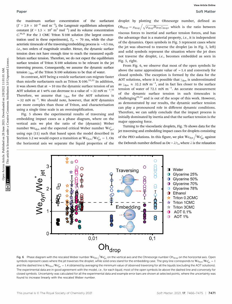
Fig. 5 shows the experimental results of traversing andembedding impact cases as a phase diagram, where on thevertical axis we plot the ratio of the (dynamic) Webernumber Wedyn and the expected critical Weber number We�jet,
using eqn (11) such that based upon the model described inSection 3.2 we would expect a transition at Wedyn=We�jet ¼ 1. On
the horizontal axis we separate the liquid properties of the
droplet by plotting the Ohnesorge number, defined as
Ohdrop ¼ mdrop. ffiffiffiffiffiffiffiffiffiffiffiffiffiffiffiffiffiffiffiffiffiffiffiffiffiffiffiffiffiffi
rdropDdropgdropp
, which is the ratio between
viscous forces to inertial and surface tension forces, and hasthe advantage that is a material property, i.e., it is independentof the dynamics. Open symbols in Fig. 5 represent cases wherethe jet was observed to traverse the droplet (as in Fig. 5, left)and solid symbols represent the situation where the jet doesnot traverse the droplet, i.e., becomes embedded as seen inFig. 5, right.
From Fig. 6, we observe that most of the open symbols lieabove the same approximate value of B1.4 and conversely forclosed symbols. The exception is formed by the data for theAOT solutions, where it is possible that gdyn is underestimatedas gdyn E 32.2 mN m�1, and in fact lies closer to the surfacetension of water of 72.1 mN m�1. An accurate measurementof the dynamic surface tension in such timescales ischallenging29,34 and is out of the scope of this work. However,as demonstrated by our results, the dynamic surface tensioncan play a pronounced role in different dynamic conditions.Therefore, we can safely conclude that the impact process isinitially dominated by inertia and that the surface tension is themajor opposing force.
Turning to the viscoelastic droplets, Fig. 7b shows data for thejet traversing and embedding impact cases for droplets consisting
of the PEO solutions. In this figure, we plot Wedyn
.We�jet against
the Deborah number defined as De = l/tc, where l is the relaxation
Fig. 6 Phase diagram with the rescaled Weber number Wedyn
.We�jet on the vertical axis and the Ohnesorge number Ohdrop on the horizontal axis. Open
symbols represent cases where the jet traverses the droplet, while solid ones stand for the embedding case. The grey line corresponds to Wedyn=We�jet ¼ 1
and the dashed line is Wedyn=We�jet ¼ 1:4 obtained by averaging the minimum value of observed traversing for all the liquids (excluding the AOT solutions).
The experimental data are in good agreement with the model, i.e., for each liquid, most of the open symbols lie above the dashed line and conversely forclosed symbols. Uncertainty was calculated for all the experimental data and example error bars are shown at selected points, where the uncertainty wasfound to increase linearly with the rescaled Weber number.
Paper Soft Matter
Ope
n A
cces
s A
rtic
le. P
ublis
hed
on 2
8 Ju
ne 2
021.
Dow
nloa
ded
on 2
/8/2
022
11:0
1:01
AM
. T
his
artic
le is
lice
nsed
und
er a
Cre
ativ
e C
omm
ons
Attr
ibut
ion
3.0
Unp
orte
d L
icen
ce.
View Article Online
7472 | Soft Matter, 2021, 17, 7466–7475 This journal is © The Royal Society of Chemistry 2021
time of the polymer (see Table 1) and tc = (rdropDdrop3/gdrop)1/2 is the
capillary timescale. We use this definition of the Deborah numberfor our PEO solution droplets, as we expect to observe deviationsfrom the Newtonian behaviour when l becomes comparable to thescale at which surface tension starts to influence the cavitydynamics, i.e., at the capillary time scale tc. In Fig. 7, open and
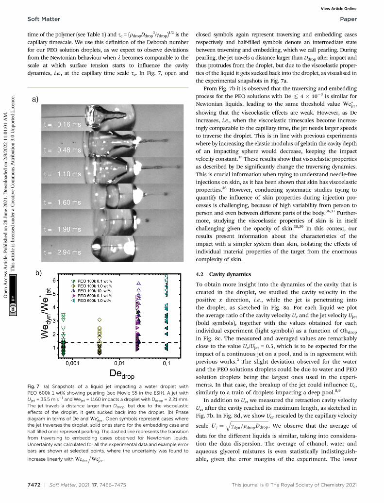
closed symbols again represent traversing and embedding casesrespectively and half-filled symbols denote an intermediate statebetween traversing and embedding, which we call pearling. Duringpearling, the jet travels a distance larger than Ddrop after impact andthus protrudes from the droplet, but due to the viscoelastic proper-ties of the liquid it gets sucked back into the droplet, as visualised inthe experimental snapshots in Fig. 7a.
From Fig. 7b it is observed that the traversing and embeddingprocess for the PEO solutions with De t 4 � 10�3 is similar forNewtonian liquids, leading to the same threshold value We�jet,
showing that the viscoelastic effects are weak. However, as Deincreases, i.e., when the viscoelastic timescales become increas-ingly comparable to the capillary time, the jet needs larger speedsto traverse the droplet. This is in line with previous experimentswhere by increasing the elastic modulus of gelatin the cavity depthof an impacting sphere would decrease, keeping the impactvelocity constant.35 These results show that viscoelastic propertiesas described by De significantly change the traversing dynamics.This is crucial information when trying to understand needle-freeinjections on skin, as it has been shown that skin has viscoelasticproperties.36 However, conducting systematic studies trying toquantify the influence of skin properties during injection pro-cesses is challenging, because of high variability from person toperson and even between different parts of the body.36,37 Further-more, studying the viscoelastic properties of skin is in itselfchallenging given the opacity of skin.38,39 In this context, ourresults present information about the characteristics of theimpact with a simpler system than skin, isolating the effects ofindividual material properties of the target from the enormouscomplexity of skin.
4.2 Cavity dynamics
To obtain more insight into the dynamics of the cavity that iscreated in the droplet, we studied the cavity velocity in thepositive x direction, i.e., while the jet is penetrating intothe droplet, as sketched in Fig. 8a. For each liquid we plotthe average ratio of the cavity velocity Uc and the jet velocity Ujet
(bold symbols), together with the values obtained for eachindividual experiment (light symbols) as a function of Ohdrop
in Fig. 8c. The measured and averaged values are remarkablyclose to the value Uc/Ujet = 0.5, which is to be expected for theimpact of a continuous jet on a pool, and is in agreement withprevious works.2 The slight deviation observed for the waterand the PEO solutions droplets could be due to water and PEOsolution droplets being the largest ones used in the experi-ments. In that case, the breakup of the jet could influence Uc,similarly to a train of droplets impacting a deep pool.8,9
In addition to Uc, we measured the retraction cavity velocityUcr after the cavity reached its maximum length, as sketched inFig. 7b. In Fig. 8d, we show Ucr rescaled by the capillary velocity
scale Ug ¼ffiffiffiffiffiffiffiffiffiffiffiffiffiffiffiffiffiffiffiffiffiffiffiffiffiffiffiffiffiffiffigdyn=rdropDdrop
q. We observe that the average of
data for the different liquids is similar, taking into considera-tion the data dispersion. The average of ethanol, water andaqueous glycerol mixtures is even statistically indistinguish-able, given the error margins of the experiment. The lower
Fig. 7 (a) Snapshots of a liquid jet impacting a water droplet withPEO 600k 1 wt% showing pearling (see Movie S5 in the ESI†). A jet withUjet = 33.5 m s�1 and Wejet = 1160 impacts a droplet with Ddrop = 2.21 mm.The jet travels a distance larger than Ddrop, but due to the viscoelasticeffects of the droplet, it gets sucked back into the droplet. (b) Phasediagram in terms of De and We�dyn. Open symbols represent cases wherethe jet traverses the droplet, solid ones stand for the embedding case andhalf filled ones represent pearling. The dashed line represents the transitionfrom traversing to embedding cases observed for Newtonian liquids.Uncertainty was calculated for all the experimental data and example errorbars are shown at selected points, where the uncertainty was found to
increase linearly with Wedyn
.We�jet.
Soft Matter Paper
Ope
n A
cces
s A
rtic
le. P
ublis
hed
on 2
8 Ju
ne 2
021.
Dow
nloa
ded
on 2
/8/2
022
11:0
1:01
AM
. T
his
artic
le is
lice
nsed
und
er a
Cre
ativ
e C
omm
ons
Attr
ibut
ion
3.0
Unp
orte
d L
icen
ce.
View Article Online

This journal is © The Royal Society of Chemistry 2021 Soft Matter, 2021, 17, 7466–7475 | 7473
average values of Ucr for the AOT and Triton solutions canpossibly be explained by the Marangoni stresses generated bythe flow from areas with low surface tension to those with highsurface tension. Indeed, Marangoni stresses have been shownto retard cavity collapse and slow the velocity of Worthingtonjets.40,41 Therefore, we can assume that Ucr p Ug, indicatingthat the retraction of the cavity is surface tension driven.42 Theorigin of the dispersion in Ucr is associated with the jet tailbreakup, where the Matryoshka effect or the creation of anantibubble may arise, like in Fig. 5.28,29
4.3 Observations after the cavity collapse
After the retraction phase, the cavity collapses and generates aWorthington jet (as e.g., depicted in the last panel of Fig. 3).Extensive studies of the length, speed and breakup time of aWorthington jet formed after droplet and solid impact on aliquid pool have been widely reported, and are outside of thescope of this paper.1,40,42–47 Moreover, given the randombreakup of the impacting jet in our experiments, the Worthing-ton jets are observed to vary widely in size and shape, evenwhen the droplet and impacting jet consist of the same liquids.This is understandable, as it has been shown in the literaturethat small disturbances in the cavity can have a strong influ-ence on the Worthington jet properties.42
Lastly, we observe that the mixing and diffusion of theimpacting jet into the droplet is governed by the dropletcharacteristics. Indeed, for a jet impacting a water droplet withAOT 0.1 wt% below the critical value U�jet needed for traversing,
there is vortical mixing (Fig. 9, left). Comparable mixing
patterns were observed (data not shown) for the rest of theNewtonian liquids containing surfactants, and weaker mixingis seen for water, ethanol and glycerine 25% droplets. Similarmixing patterns have been described in the literature, forexample, Jia et al. in 202040 reported an interfacial Marangoniflow enhancing the mixing of an impacting droplet and a liquidpool with different surface tensions.
We note that in our experiments the surface tension of thejet is almost always expected to be different from the surfacetension of the droplet, and a Marangoni flow could explain thistype of mixing. However, a more in depth study is needed toconfirm this hypothesis. In contrast, for the viscoelastic liquidswith De \ 2 � 10�2 and the glycerol mixture liquids withOh \ 0.02, the jet does not mix with the droplet in thetimescale of our experiments (Fig. 9, right). Furthermore,low viscosity (Oh t 0.01) and low surface tension liquidsreach equilibrium at a later stage than more viscous liquids(Oh \ 0.02) and with higher surface tension. For example, inFig. 9 a PEO 600k 1 wt% droplet reaches equilibrium B4 timesfaster than the AOT droplet. This is expected, as surface tensionand viscosity have been observed to affect droplet oscillations.48,49
5 Conclusions
We have presented experimental results of liquid water jetsimpacting on pendant droplets with different liquid properties.We proposed two models to predict a critical jet impact velocitybeyond which the jet traverses the droplet. First, we presented amodel based on a simple energy balance between the jet kinetic
Fig. 8 Sketch illustrating the definitions of (a) the cavity velocity Uc and (b) the velocity of the retracting cavity Ucr. (c) Ratio of the cavity velocity Uc andthe impact velocity Ujet, compared to the expected value of 0.5. (d) Ucr divided by the capillary velocity scale Ug ¼
ffiffiffiffiffiffiffiffiffiffiffiffiffiffiffiffiffiffiffiffiffiffiffiffiffiffiffiffiffiffiffigdyn=rdropDdrop
q; average values for
each liquid are statistically similar, indicating that the retraction of the cavity is governed by capillary forces. For each liquid, bold coloured symbolsrepresent average values of light symbols.
Paper Soft Matter
Ope
n A
cces
s A
rtic
le. P
ublis
hed
on 2
8 Ju
ne 2
021.
Dow
nloa
ded
on 2
/8/2
022
11:0
1:01
AM
. T
his
artic
le is
lice
nsed
und
er a
Cre
ativ
e C
omm
ons
Attr
ibut
ion
3.0
Unp
orte
d L
icen
ce.
View Article Online

7474 | Soft Matter, 2021, 17, 7466–7475 This journal is © The Royal Society of Chemistry 2021
energy and the change in surface tension of the droplet. Thesecond model is based on the comparison between the Young–Laplace and the dynamic pressures of the cavity made by thepenetrating jet, and its shape is described by the two-dimensional Rayleigh equation.
Although the critical velocity predicted in both models is ofthe same order of magnitude, they differ in their scalingrelation with Ddrop/Djet. The difference arises from the differentdescription of the cavity geometry and its associated surfaceenergy. In the energy balance model, a cylindrical shape isassumed, contrasting with the more accurate cavity shapedescribed by the two-dimensional Rayleigh equation. Further-more, we tested the validity of the second model, by fitting ourexperimental data with eqn (11), showing good agreementwhen dynamic surface tension effects are considered, seeFig. 6. Therefore, for Newtonian droplets the impact processis initially dominated by inertia and their dynamic surfacetension is the major opposing force.
In addition, we investigated viscoelastic effects by usingwater-based polyethylene-oxide solutions of varied concentra-tions and molecular weight. For De t 4� 10�3, the droplets actas if they were Newtonian. In contrast, for De \ 2 � 10�2, agreater jet impact speed is necessary to traverse the droplet,indicating that when the capillary and relaxation times arecomparable, viscoelastic effects can dominate the traversingphenomena. Moreover, we observed a distinct transitionphenomenon from traversing to embedding, which we called
pearling and during which the protruding jet is sucked backinto the droplet.
Next, we investigated the advancing and retraction velocitiesUc and Ucr of the cavity, confirming previous reports thatUc/Ujet B 0.5 for different liquids. Furthermore, we found thatUcr is surface tension driven, with the connotation that fordroplets containing surfactants Ucr is observed to be slowerthan for the other liquids that were used, which could beexplained by Marangoni stresses.
Our results are relevant for needle-free injections into softtissues such as skin, or the eyes, where controlling the jetvelocity, U�jet, would be essential to avoid undesired tissue
damage and ensure successful drug delivery.
Author contributions
M. A. Q. S., D. v. d. M. and D. F. R. conceived the experiments,analysed the results and wrote the manuscript. M. A. Q. S. andD. F. R. designed and built the experimental setup. M. A. Q. S.performed the experiments. I. W. H. participated in the discus-sions and wrote the manuscript.
Conflicts of interest
There are no conflicts to declare.
Acknowledgements
This research was funded by the European Research Council(ERC) under the European Union Horizon 2020 Research andInnovation Programme (grant agreement no. 851630). Wethank Loreto Oyarte-Galvez, Javier Rodrıguez-Rodrıguez, AlvaroMarın, Ivo Peters and Detlef Lohse for the valuable discussions.We also thank Ambre Bouillant and Ali Rezaei for their assis-tance in the shear viscosity measurements. The guidance ofJames W. Bales and Andrew Davidhazy through Edgerton’sDigital Collection was of great value. David Fernandez Rivaswould like to thank Gareth McKinley for his input at the start ofthe project and for hosting his stay at the HML and the MIT.
Notes and references
1 A. M. Worthington, A study of splashes, Longmans, Green,and Company, 1908.
2 H. N. Oguz, A. Prosperetti and A. R. Kolaini, J. Fluid Mech.,1995, 294, 181–207.
3 M. Lee, R. Longoria and D. Wilson, Phys. Fluids, 1997, 9,540–550.
4 Y. Zhu, H. N. Oguz and A. Prosperetti, J. Fluid Mech., 2000,404, 151–177.
5 E. Lorenceau, D. Quere and J. Eggers, Phys. Rev. Lett., 2004,93, 254501.
6 J. M. Aristoff and J. W. Bush, J. Fluid Mech., 2009, 619, 45–78.7 T. T. Truscott, B. P. Epps and J. Belden, Annu. Rev. Fluid
Mech., 2014, 46, 355–378.
Fig. 9 Mixing after impact and cavity collapse. Left, jet impacting an AOT0.1 wt% droplet with Wejet = 359. In the sequence we observe vorticalmixing presumably due to the Marangoni flow caused by the difference ofsurface tension between the jet and the droplet (see Movie S6 in the ESI†and Jia et al. 202040). Right, jet impacting a PEO 600k 1 wt% withWejet = 574. In this sequence we observe little mixing and diffusion dueto the viscoelastic properties of the droplet even after 0.42 ms.
Soft Matter Paper
Ope
n A
cces
s A
rtic
le. P
ublis
hed
on 2
8 Ju
ne 2
021.
Dow
nloa
ded
on 2
/8/2
022
11:0
1:01
AM
. T
his
artic
le is
lice
nsed
und
er a
Cre
ativ
e C
omm
ons
Attr
ibut
ion
3.0
Unp
orte
d L
icen
ce.
View Article Online

This journal is © The Royal Society of Chemistry 2021 Soft Matter, 2021, 17, 7466–7475 | 7475
8 W. Bouwhuis, X. Huang, C. U. Chan, P. E. Frommhold,C.-D. Ohl, D. Lohse, J. H. Snoeijer and D. van der Meer,J. Fluid Mech., 2016, 792, 850–868.
9 N. B. Speirs, Z. Pan, J. Belden and T. T. Truscott, J. FluidMech., 2018, 844, 1084.
10 H. E. Edgerton, Electr. Eng., 1931, 50, 327–329.11 M. R. Prausnitz, S. Mitragotri and R. Langer, Nat. Rev. Drug
Discovery, 2004, 3, 115–124.12 N. C. Hogan, A. J. Taberner, L. A. Jones and I. W. Hunter,
Expert Opin. Drug Delivery, 2015, 12, 1637–1648.13 A. Mohizin and J. K. Kim, J. Mech. Sci. Technol., 2018, 32,
5737–5747.14 S. F. Rastopov and A. T. Sukhodolsky, Optical Radiation
Interaction with Matter, 1991, pp. 127–134.15 J. Padilla-Martınez, C. Berrospe-Rodriguez, G. Aguilar,
J. Ramirez-San-Juan and R. Ramos-Garcia, Phys. Fluids,2014, 26, 122007.
16 C. B. Rodrıguez, C. W. Visser, S. Schlautmann, D. F. Rivasand R. Ramos-Garcia, J. Biomed. Opt., 2017, 22, 105003.
17 L. Oyarte Galvez, A. Fraters, H. L. Offerhaus, M. Versluis,I. W. Hunter and D. Fernandez Rivas, J. Appl. Phys., 2020,127, 104901.
18 K. Cu, R. Bansal, S. Mitragotri and D. F. Rivas, Ann. Biomed.Eng., 2019, 1–12.
19 L. Oyarte Galvez, M. Brio Perez and D. Fernandez Rivas,J. Appl. Phys., 2019, 125, 144504.
20 A. Daerr and A. Mogne, J. Open Res. Softw., 2016, 4, e3.21 M. Grotte, F. Duprat, D. Loonis and E. Pietri, Int. J. Food
Prop., 2001, 4, 149–161.22 T. Truscott, A. Techet and D. Beal, Proceedings of the
International Symposium on Cavitation, 2009.23 G. Birkhoff, D. P. MacDougall, E. M. Pugh and S. G. Taylor,
J. Appl. Phys., 1948, 19, 563–582.24 K. T. Kiger and J. H. Duncan, Annu. Rev. Fluid Mech., 2012,
44, 563–596.25 Q. Deng, A. Anilkumar and T. Wang, J. Fluid Mech., 2007,
578, 119–138.26 R. Bergmann, D. van der Meer, M. Stijnman, M. Sandtke,
A. Prosperetti and D. Lohse, Phys. Rev. Lett., 2006,96, 154505.
27 J. Eggers, M. Fontelos, D. Leppinen and J. Snoeijer,Phys. Rev. Lett., 2007, 98, 094502.
28 Y. Song, L. Zhang and E. N. Wang, Phys. Rev. Fluids, 2020,5, 123601.
29 N. Speirs, M. Mansoor, R. Hurd, S. Sharker, W. Robinson,B. Williams and T. T. Truscott, Phys. Rev. Fluids, 2018,3, 104004.
30 A. Bobylev, V. Guzanov, A. Kvon and S. Kharlamov, J. Phys.:Conf. Ser., 2019, 012073.
31 J. K. Ferri and K. J. Stebe, Adv. Colloid Interface Sci., 2000, 85,61–97.
32 M. Song, J. Ju, S. Luo, Y. Han, Z. Dong, Y. Wang, Z. Gu,L. Zhang, R. Hao and L. Jiang, Sci. Adv., 2017, 3,e1602188.
33 T. Wang, Y. Si, S. Luo, Z. Dong and L. Jiang, Mater. Horiz.,2019, 6, 294–301.
34 N. J. Alvarez, L. M. Walker and S. L. Anna, Langmuir, 2010,26, 13310–13319.
35 A. Kiyama, M. M. Mansoor, N. B. Speirs, Y. Tagawa andT. T. Truscott, J. Fluid Mech., 2019, 880, 707–722.
36 Y.-c. Fung, Biomechanics: mechanical properties of livingtissues, Springer Science & Business Media, 2013.
37 H. Joodaki and M. B. Panzer, Proc. Inst. Mech. Eng., Part H,2018, 232, 323–343.
38 M. L. Crichton, B. C. Donose, X. Chen, A. P. Raphael,H. Huang and M. A. Kendall, Biomaterials, 2011, 32,4670–4681.
39 H. K. Graham, J. C. McConnell, G. Limbert andM. J. Sherratt, Exp. Dermatol., 2019, 28, 4–9.
40 F. Jia, K. Sun, P. Zhang, C. Yin and T. Wang, Phys. Rev.Fluids, 2020, 5, 073605.
41 C. Constante-Amores, L. Kahouadji, A. Batchvarov, S. Shin,J. Chergui, D. Juric and O. Matar, J. Fluid Mech., 2021,911, A57.
42 G.-J. Michon, C. Josserand and T. Seon, Phys. Rev. Fluids,2017, 2, 023601.
43 J. Cheny and K. Walters, J. Non-Newtonian Fluid Mech., 1996,67, 125–135.
44 S. Gekle and J. M. Gordillo, J. Fluid Mech., 2010, 663, 293.45 Z. Che and O. K. Matar, Soft Matter, 2018, 14, 1540–1551.46 A. Mohammad Karim, Phys. Fluids, 2020, 32, 043102.47 D. Kim, J. Lee, A. Bose, I. Kim and J. Lee, J. Fluid Mech., 2021,
906, A5.48 J. Kremer, A. Kilzer and M. Petermann, Rev. Sci. Instrum.,
2018, 89, 015109.49 J. Arcenegui-Troya, A. Belman-Martnez, A. Castrejon-Pita
and J. Castrejon-Pita, Rev. Sci. Instrum., 2019, 90,095109.
Paper Soft Matter
Ope
n A
cces
s A
rtic
le. P
ublis
hed
on 2
8 Ju
ne 2
021.
Dow
nloa
ded
on 2
/8/2
022
11:0
1:01
AM
. T
his
artic
le is
lice
nsed
und
er a
Cre
ativ
e C
omm
ons
Attr
ibut
ion
3.0
Unp
orte
d L
icen
ce.
View Article Online