Embed Size (px)
Citation preview
International Research Journal of Engineering and Technology (IRJET) e-ISSN: 2395-0056
Volume: 04 Issue: 07 | July -2017 www.irjet.net p-ISSN: 2395-0072
© 2017, IRJET | Impact Factor value: 5.181 | ISO 9001:2008 Certified Journal | Page 2187
Voltage Variation Compensation
Krishnapriya M.R1, Minnu Mariya Paul2, Ridhun R3 , Veena Mathew4
1,2,3 Student, Dept. of Electrical And Electronics Engineering, Mar Athanasius College, Kerala, India 4 Assistant Professor, Dept. of Electrical And Electronics Engineering, Mar Athanasius College,
Kerala, India ---------------------------------------------------------------------***---------------------------------------------------------------------
Abstract - Power quality is one of the major concerns in the present era. Power distribution systems, ideally should provide customer with an uninterrupted flow of energy at smooth Sinusoidal voltage. But in practice distribution systems have non linear loads which affects the purity of waveform of supply. One of the major problems dealt here is voltage sag and swell. The proposed system can provide a solution to the above problem by using a renewable energy source like solar. It uses a PIC microcontroller and atmel microcontroller. PIC microcontroller compares the load voltage and give signals to atmel microcontroller based on whether there is a voltage sag or swell. The atmel microcontroller correspondingly controls the pulse width of the inverter and gives the necessary compensation. Key Words: Renewable energy, pulse width, microcontroller, Atmel, PIC 1.INTRODUCTION Recently, much attention has been focused on the power quality domain in power system networks. Power quality measures the fitness of electric power transmitted from the utilities to the different consumers in the case of the conventional centralized generation or in some cases from the consumers to the utilities in the case of distributed generation. Voltage distortion that may occur due to power system harmonics and voltage sags is widely recognized as the most severe issue affecting power quality, because it affects both the utility company and consumers alike. Nonlinear loads create voltage and current harmonics which may have detrimental effects on consumers equipment. There are two major challenges that power system must deal with: one is voltage fluctuations and the other is short circuit faults. Nowadays, many power loads have become more sensitive to the disturbances due to voltage fluctuations that are produced because of wide use of non-linear loads. Because of these disturbances or fluctuations quality of power being distributed or transmitted has become low. Faults in power system can cause voltage sag or swell in the entire system or major part of it. In addition, harmonics, voltage transients, flickers are also one of the voltage quality problems .Voltage sag can be either balanced or unbalanced which mainly depends on type of fault. The main sources of voltage sag are any type of fault in power system or by the starting of large motor loads. Mainly, voltage sags are considered as major threats to the power quality. But
voltage swells are less frequent compared to that of voltage sags which are mainly produced because of sudden switching of large loads or energization of capacitor banks. Due to these faults, under full load conditions, it may cause severe or high voltage drops in the system. Due to these disturbances, system may undergo shutdown or fail including large voltage and current imbalances in the system. Various techniques can be adopted or used by the customer in order to mitigate these voltage sags / swells to have better quality of power supply to the equipment for its effective functioning. But, the effects that are caused by the voltage sag or swell to the equipment may be expensive to the customer. But, there are many techniques available for compensation of voltage sag and swell, in which installation of custom power device is the adequate method for mitigation of voltage sag and swell. A power conditioner is a device proposed to enhance the quality of the power that is delivered to a sensitive electrical load. In addition, it can be defined as a device that acts on delivery of a voltage of the appropriate level and characteristics to facilitate the effective utilization of critical loads. At the present time, one of the power conditioners most commonly used to mitigate voltage sags is the dynamic voltage restorer (DVR). Renewable energy sources such as wind, solar, tidal etc can be used for the same. In this project, we are using solar for mitigation of voltage sag and swell. This project presents a hardware prototype of a voltage sag and swell compensator which ensures a constant and steady voltage across the load with less fluctuations. The controller is implemented using the PIC16F877Microcontroller and Atmel Microcontroller launch pad kit. 2.BLOCK DIAGRAM DESCRIPTION The system shown above is used to compensate for the variations that occur in the load voltage. Required voltage is attained from solar energy. Sun light incident on the solar cell is converted into electrical energy using photovoltaic effect. This electrical energy is boosted using a dc-dc boost converter and is then stored in a battery. The boosted output depends on the trigger pulse given by the pic microcontroller. Output of battery is given to an inverter for dc to ac conversion. In the above system , supply is provided by an autotransformer which is adjusted to provide sag and swell conditions. Autotransformer is connected in series with an injection transformer across the ac load. Two microcontrollers , PIC
International Research Journal of Engineering and Technology (IRJET) e-ISSN: 2395-0056
Volume: 04 Issue: 07 | July -2017 www.irjet.net p-ISSN: 2395-0072
© 2017, IRJET | Impact Factor value: 5.181 | ISO 9001:2008 Certified Journal | Page 2188
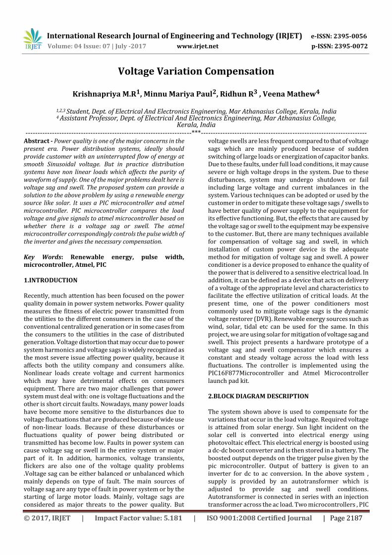
and Atmel are used to control the voltage variations. PIC microcontroller is the first RISC based microcontroller fabricated in CMOS (complementary metal oxide semiconductor) technology. It has separate buses for instruction and data flow for simultaneous access of program and data memory. The main advantage of CMOS and RISC combination is low power consumption resulting in a very small chip size with a small pin count. Here it is used for controlling booster output and also to send signals to atmel for nay variation in load voltage. The Atmel AT89C51 is a low-power, high-performance CMOS 8-bit microcomputer with 4K bytes of Flash Programmable and Erasable Read Only Memory (PEROM). The device is manufactured using Atmels high density nonvolatile memory technology. The voltage measurement block measures the load voltage, solar voltage, boost output and the source voltage. All values are displayed using an LCD. Load voltage is then compared with a reference value and for any variation in the load voltage pic microcontroller sends a signal to Atmel microcontroller. Atmel microcontroller correspondingly triggers the inverter and thereby controls its output. Output of the inverter is given to the primary of the injection transformer which is in series with the supply. For any variations in the load voltage, microcontroller controls the inverter output and compensate for the variation.
Fig-1: Block Diagram 3.SIMULATIONMODELS AND OUTPUT WAVEFORMS 3.1Circuit Diagram Figure 2 shows the simulation of the circuit. Source is used to provide the ac supply voltage, which is measured by the voltage measurement block and is displayed. Source side load is used to provide the sag and swell conditions. This source voltage is connected in series with secondary of a 3 phase transformer and load is connected across this.
Primary of the transformer is fed from a solar PV module through an inverter and a filter. The boosted dc output of the solar panel is converted to ac voltage in an inverter which is then filtered and given to the transformer through a breaker. The breaker operates only when sag or swell occur in the load voltage. The supply voltage adds up with this voltage and maintains a constant voltage across the load.
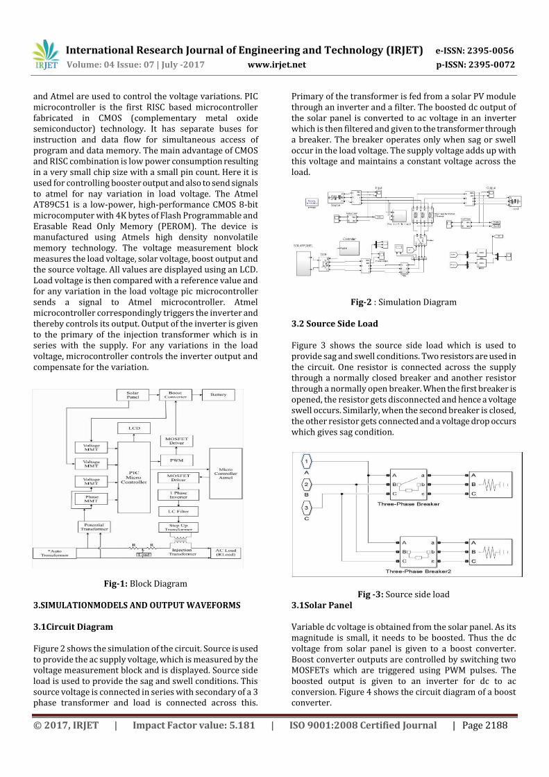
Fig-2 : Simulation Diagram 3.2 Source Side Load Figure 3 shows the source side load which is used to provide sag and swell conditions. Two resistors are used in the circuit. One resistor is connected across the supply through a normally closed breaker and another resistor through a normally open breaker. When the first breaker is opened, the resistor gets disconnected and hence a voltage swell occurs. Similarly, when the second breaker is closed, the other resistor gets connected and a voltage drop occurs which gives sag condition.
Fig -3: Source side load 3.1Solar Panel Variable dc voltage is obtained from the solar panel. As its magnitude is small, it needs to be boosted. Thus the dc voltage from solar panel is given to a boost converter. Boost converter outputs are controlled by switching two MOSFETs which are triggered using PWM pulses. The boosted output is given to an inverter for dc to ac conversion. Figure 4 shows the circuit diagram of a boost converter.
International Research Journal of Engineering and Technology (IRJET) e-ISSN: 2395-0056
Volume: 04 Issue: 07 | July -2017 www.irjet.net p-ISSN: 2395-0072
© 2017, IRJET | Impact Factor value: 5.181 | ISO 9001:2008 Certified Journal | Page 2189
Fig -4: Solar panel 3.2 Results Figure 5 shows the voltage and current waveforms of the supply. It can be seen that voltage waveforms are not constant throughout. There are many variations such as voltage sag and swell occurring in the supply voltage for short durations of time.
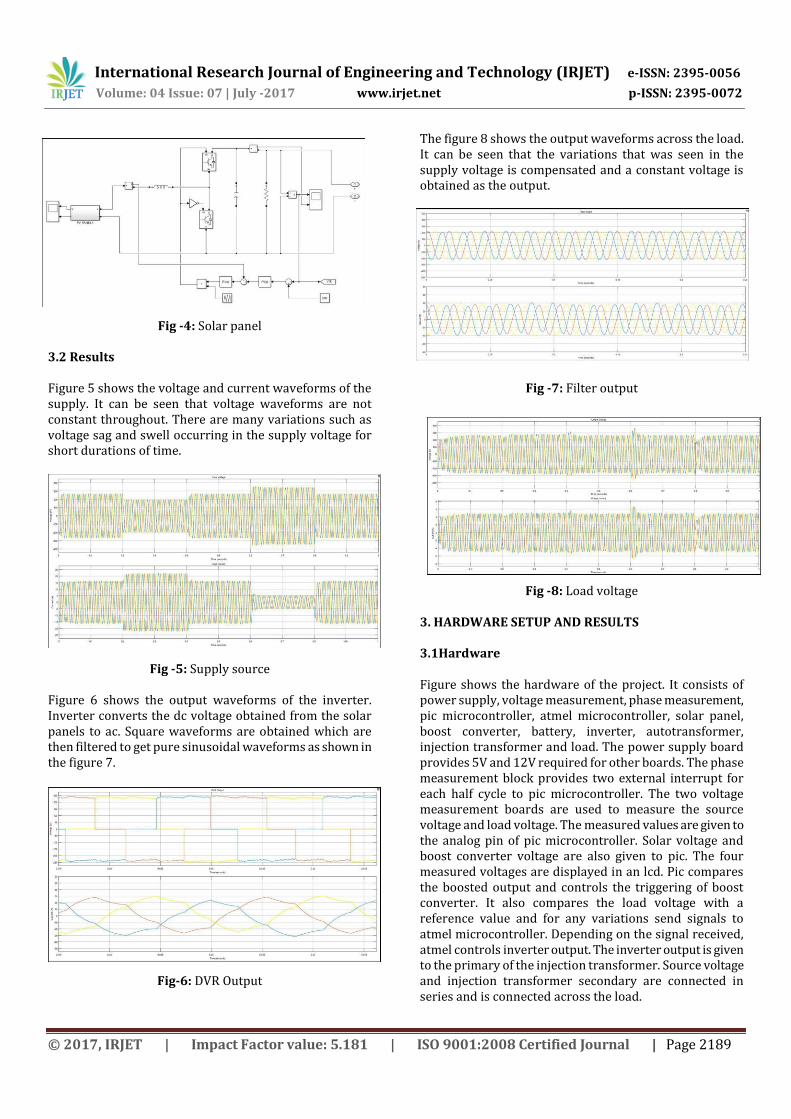
Fig -5: Supply source Figure 6 shows the output waveforms of the inverter. Inverter converts the dc voltage obtained from the solar panels to ac. Square waveforms are obtained which are then filtered to get pure sinusoidal waveforms as shown in the figure 7.
Fig-6: DVR Output
The figure 8 shows the output waveforms across the load. It can be seen that the variations that was seen in the supply voltage is compensated and a constant voltage is obtained as the output.
Fig -7: Filter output
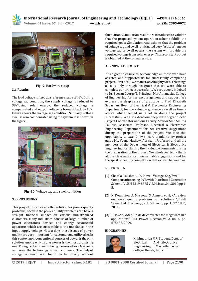
Fig -8: Load voltage 3. HARDWARE SETUP AND RESULTS 3.1Hardware Figure shows the hardware of the project. It consists of power supply, voltage measurement, phase measurement, pic microcontroller, atmel microcontroller, solar panel, boost converter, battery, inverter, autotransformer, injection transformer and load. The power supply board provides 5V and 12V required for other boards. The phase measurement block provides two external interrupt for each half cycle to pic microcontroller. The two voltage measurement boards are used to measure the source voltage and load voltage. The measured values are given to the analog pin of pic microcontroller. Solar voltage and boost converter voltage are also given to pic. The four measured voltages are displayed in an lcd. Pic compares the boosted output and controls the triggering of boost converter. It also compares the load voltage with a reference value and for any variations send signals to atmel microcontroller. Depending on the signal received, atmel controls inverter output. The inverter output is given to the primary of the injection transformer. Source voltage and injection transformer secondary are connected in series and is connected across the load.
International Research Journal of Engineering and Technology (IRJET) e-ISSN: 2395-0056
Volume: 04 Issue: 07 | July -2017 www.irjet.net p-ISSN: 2395-0072
© 2017, IRJET | Impact Factor value: 5.181 | ISO 9001:2008 Certified Journal | Page 2190
Fig -9: Hardware setup
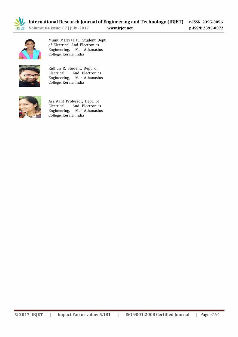
3.1 Results The load voltage is fixed at a reference value of 48V. During voltage sag condition, the supply voltage is reduced to 38V.Using solar energy, the reduced voltage is compensated and output voltage is brought back to 48V. Figure shows the voltage sag condition. Similarly voltage swell is also compensated using the system. It is shown in the figure.
Fig -10: Voltage sag and swell condition 3. CONCLUSIONS This project describes a better solution for power quality problems, because the power quality problems can have a straight financial impact on various industrialized customers. Many industries consist of large number of power electronics devices and energy resourceful apparatus which are susceptible to the unbalance in the input supply voltage. Now a days these issues of power quality are very important for customer and utility also. In this context non-conventional sources of power is the only solution among which solar power is the most promising one. Though solar power is being harnessed for a few years and now the technology is in its infancy. The output voltage obtained was found to be steady without
fluctuations. Simulation results are introduced to validate that the proposed system operation scheme fulfills the required goals. Simulation result shows that the problem of voltage sag and swell is mitigated very fastly. Whenever voltage sag or swell occurs, the system will provide the required voltage from solar energy. Thus a constant output is obtained at the consumer side. ACKNOWLEDGEMENT It is a great pleasure to acknowledge all those who have assisted and supported us for successfully completing project. First of all, we thank God Almighty for his blessings as it is only through his grace that we were able to complete our project successfully. We are deeply indebted to Dr. Soosan George T, Principal, Mar Athanasius College of Engineering for her encouragement and support. We express our deep sense of gratitude to Prof. Elizabeth Sebastian, Head of Electrical & Electronics Engineering Department, for the valuable guidance as well as timely advice which helped us a lot in doing the project successfully. We also extend our deep sense of gratitude to Project Coordinator and our Faculty Advisor Smt. Smitha Paulose, Associate Professor, Electrical & Electronics Engineering Department for her creative suggestions during the preparation of the project. We take this opportunity to extend my sincere thanks to my project guide Ms. Veena Mathew, Assistant Professor and all the members of the Department of Electrical & Electronics Engineering for sharing their valuable comments during the preparation of the project. We wholeheartedly thank all our classmates, for their valuable suggestions and for the spirit of healthy competition that existed between us. REFERENCES [1] Chatala Lakshmii, “A Novel Voltage Sag/Swell
Compensation using DVR with Distributed Generation Scheme ", ISSN 2319-8885 Vol.04,Issue.04 , 2010;pp 1-5.
[2] N. Denniston, A. Massoud, S. Ahmed, et al, \A review
on power quality problems and solutions ", IEEE Trans. Ind. Electron., , vol. 58, no. 5, pp. 1877 1886, 2011.
[3] D. Jovcic, \Step-up dc dc converter for megawatt size
applications,", IET Power Electron.,vol.2, no. 6, pp. 675685, 2009.
BIOGRAPHIES
Krishnapriya MR, Student, Dept. of Electrical And Electronics Engineering, Mar Athanasius College, Kerala, India
International Research Journal of Engineering and Technology (IRJET) e-ISSN: 2395-0056
Volume: 04 Issue: 07 | July -2017 www.irjet.net p-ISSN: 2395-0072
© 2017, IRJET | Impact Factor value: 5.181 | ISO 9001:2008 Certified Journal | Page 2191
Minnu Mariya Paul, Student, Dept. of Electrical And Electronics Engineering, Mar Athanasius College, Kerala, India
Ridhun R, Student, Dept. of
Electrical And Electronics Engineering, Mar Athanasius College, Kerala, India
Assistant Professor, Dept. of
Electrical And Electronics Engineering, Mar Athanasius College, Kerala, India