Embed Size (px)
Citation preview
International Journal of Electrical Engineering. ISSN 0974-2158 Volume 5, Number 7 (2012), pp. 889-902 © International Research Publication House http://www.irphouse.com
Voltage Sags in Distribution Systems with Induction Motor Loads Fed by Power Converters and Voltage
Mitigation using DVR and D-STATCOM
P.N.K. Sreelatha1, J. Praveen2 and V. Kamaraju3
1Research scholar JNTUH, Hyderabad, India, [email protected]
2Principal NREC, Hyderabad, India, [email protected] 3Professor EEE MIST, Hyderabad, India, [email protected]
Abstract
In Industrial area one 11KV feeder feeds an Induction motor load of variable power and then the normal domestic to industrial loads. Faults at Induction motor load effect the other feeder loads. This paper deals with the voltage dips and correction with DVR and D-STATCOM at the desired load point is studied by simulation. Keywords- DVR, D-STATCOM, Distribution feeders, faults, power quality, voltage sag, induction motor
I. INTRODUCTION Electrical Power quality is the degree of any deviation from the nominal values of the voltage magnitude and frequency[1]. Distribution system consists of industrial, commercial and domestic loads with the utility. Industrial process contains sensitive and critical loads which include computers, power electronics-controlled motor drives as well as low-power electronic devices such as process control equipment. Disturbances such as voltage sags and swells, short duration interruptions, harmonics and transients may disrupt the processes and lead to considerable economic loss[2]. Some common reason for voltage sags are lightning strikes in power lines, equipment failures, accidental contact power lines, and electrical machine starts.Faults at either the transmission or distribution level may cause transient voltage sag either in the entire system or in a large part of it. Voltage sags can be defined as momentary reductions in supply voltage, lasting from a few milliseconds to a few cycles[3].Dynamic voltage restorer(DVR) and Distribution Static Compensator (D-STATCOM) can be used to correct the voltage
890 P.N.K. Sreelatha et al
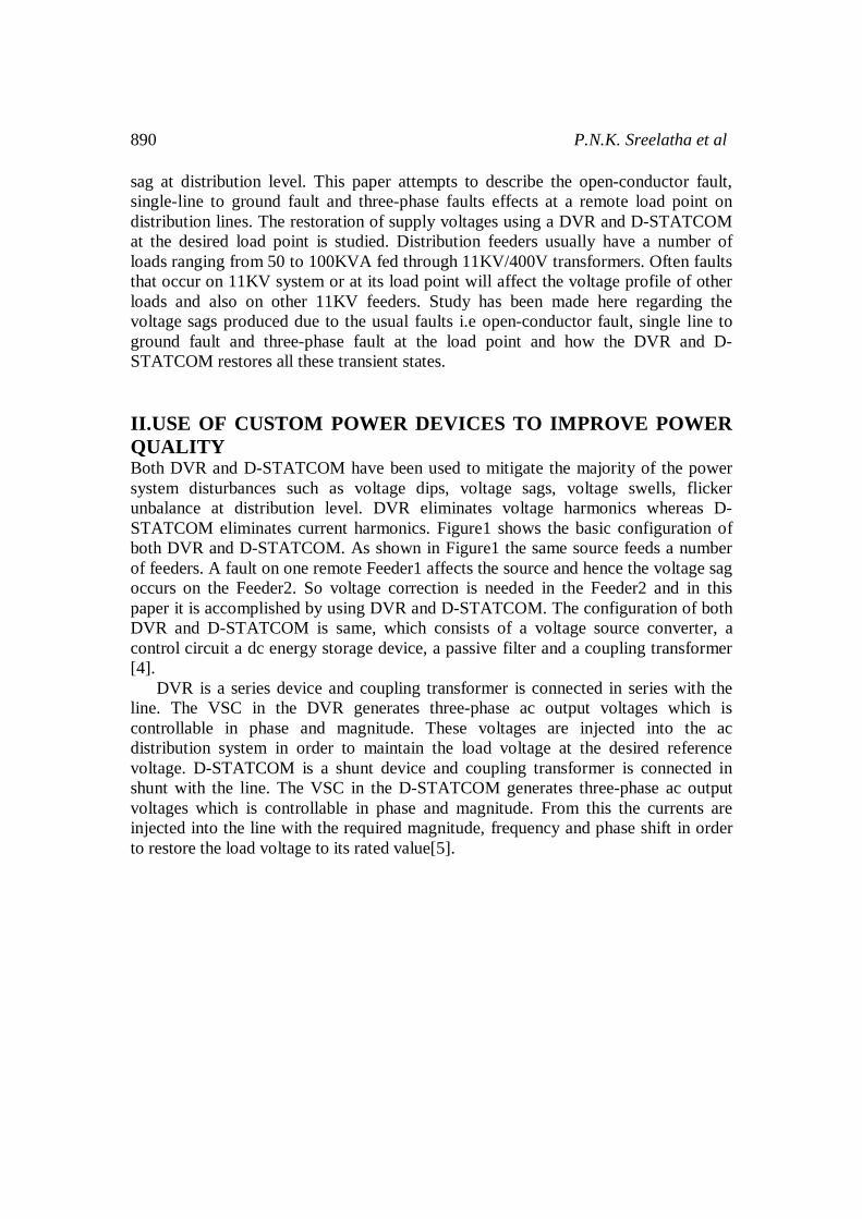
sag at distribution level. This paper attempts to describe the open-conductor fault, single-line to ground fault and three-phase faults effects at a remote load point on distribution lines. The restoration of supply voltages using a DVR and D-STATCOM at the desired load point is studied. Distribution feeders usually have a number of loads ranging from 50 to 100KVA fed through 11KV/400V transformers. Often faults that occur on 11KV system or at its load point will affect the voltage profile of other loads and also on other 11KV feeders. Study has been made here regarding the voltage sags produced due to the usual faults i.e open-conductor fault, single line to ground fault and three-phase fault at the load point and how the DVR and D-STATCOM restores all these transient states. II.USE OF CUSTOM POWER DEVICES TO IMPROVE POWER QUALITY Both DVR and D-STATCOM have been used to mitigate the majority of the power system disturbances such as voltage dips, voltage sags, voltage swells, flicker unbalance at distribution level. DVR eliminates voltage harmonics whereas D-STATCOM eliminates current harmonics. Figure1 shows the basic configuration of both DVR and D-STATCOM. As shown in Figure1 the same source feeds a number of feeders. A fault on one remote Feeder1 affects the source and hence the voltage sag occurs on the Feeder2. So voltage correction is needed in the Feeder2 and in this paper it is accomplished by using DVR and D-STATCOM. The configuration of both DVR and D-STATCOM is same, which consists of a voltage source converter, a control circuit a dc energy storage device, a passive filter and a coupling transformer [4]. DVR is a series device and coupling transformer is connected in series with the line. The VSC in the DVR generates three-phase ac output voltages which is controllable in phase and magnitude. These voltages are injected into the ac distribution system in order to maintain the load voltage at the desired reference voltage. D-STATCOM is a shunt device and coupling transformer is connected in shunt with the line. The VSC in the D-STATCOM generates three-phase ac output voltages which is controllable in phase and magnitude. From this the currents are injected into the line with the required magnitude, frequency and phase shift in order to restore the load voltage to its rated value[5].
Voltage Sags in Distribution Systems with Induction Motor Loads Fed 891
Figure1. Basic configuration of (a)D-STATCOM and DVR
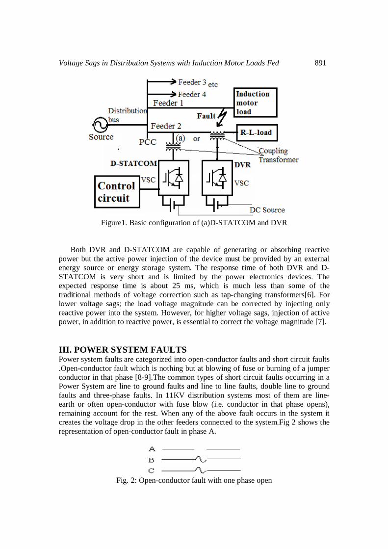
Both DVR and D-STATCOM are capable of generating or absorbing reactive power but the active power injection of the device must be provided by an external energy source or energy storage system. The response time of both DVR and D-STATCOM is very short and is limited by the power electronics devices. The expected response time is about 25 ms, which is much less than some of the traditional methods of voltage correction such as tap-changing transformers[6]. For lower voltage sags; the load voltage magnitude can be corrected by injecting only reactive power into the system. However, for higher voltage sags, injection of active power, in addition to reactive power, is essential to correct the voltage magnitude [7]. III. POWER SYSTEM FAULTS Power system faults are categorized into open-conductor faults and short circuit faults .Open-conductor fault which is nothing but at blowing of fuse or burning of a jumper conductor in that phase [8-9].The common types of short circuit faults occurring in a Power System are line to ground faults and line to line faults, double line to ground faults and three-phase faults. In 11KV distribution systems most of them are line-earth or often open-conductor with fuse blow (i.e. conductor in that phase opens), remaining account for the rest. When any of the above fault occurs in the system it creates the voltage drop in the other feeders connected to the system.Fig 2 shows the representation of open-conductor fault in phase A.
Fig. 2: Open-conductor fault with one phase open
892 P.N.K. Sreelatha et al
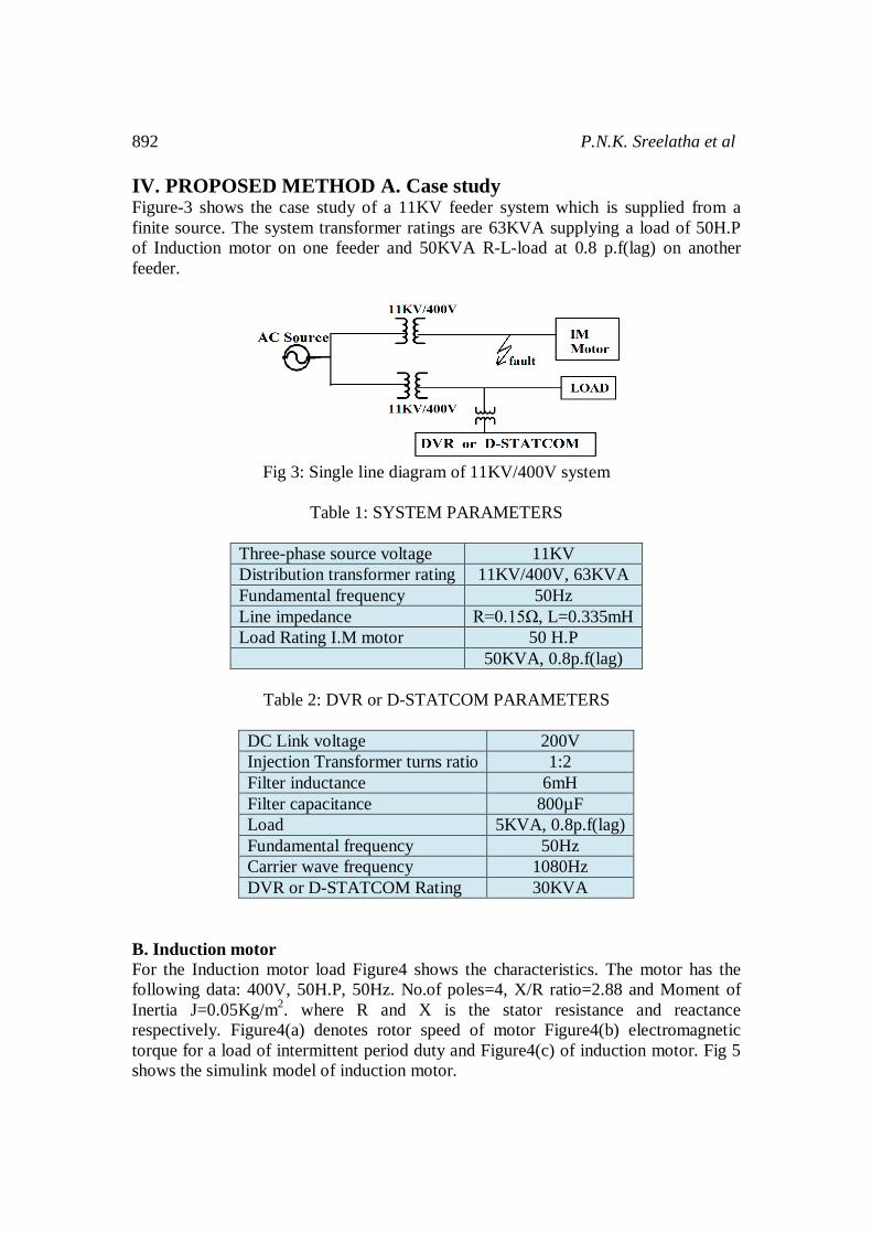
IV. PROPOSED METHOD A. Case study Figure-3 shows the case study of a 11KV feeder system which is supplied from a finite source. The system transformer ratings are 63KVA supplying a load of 50H.P of Induction motor on one feeder and 50KVA R-L-load at 0.8 p.f(lag) on another feeder.
Fig 3: Single line diagram of 11KV/400V system
Table 1: SYSTEM PARAMETERS
Three-phase source voltage 11KV Distribution transformer rating 11KV/400V, 63KVA Fundamental frequency 50Hz Line impedance R=0.15Ω, L=0.335mH Load Rating I.M motor 50 H.P 50KVA, 0.8p.f(lag)
Table 2: DVR or D-STATCOM PARAMETERS
DC Link voltage 200V Injection Transformer turns ratio 1:2 Filter inductance 6mH Filter capacitance 800µF Load 5KVA, 0.8p.f(lag) Fundamental frequency 50Hz Carrier wave frequency 1080Hz DVR or D-STATCOM Rating 30KVA
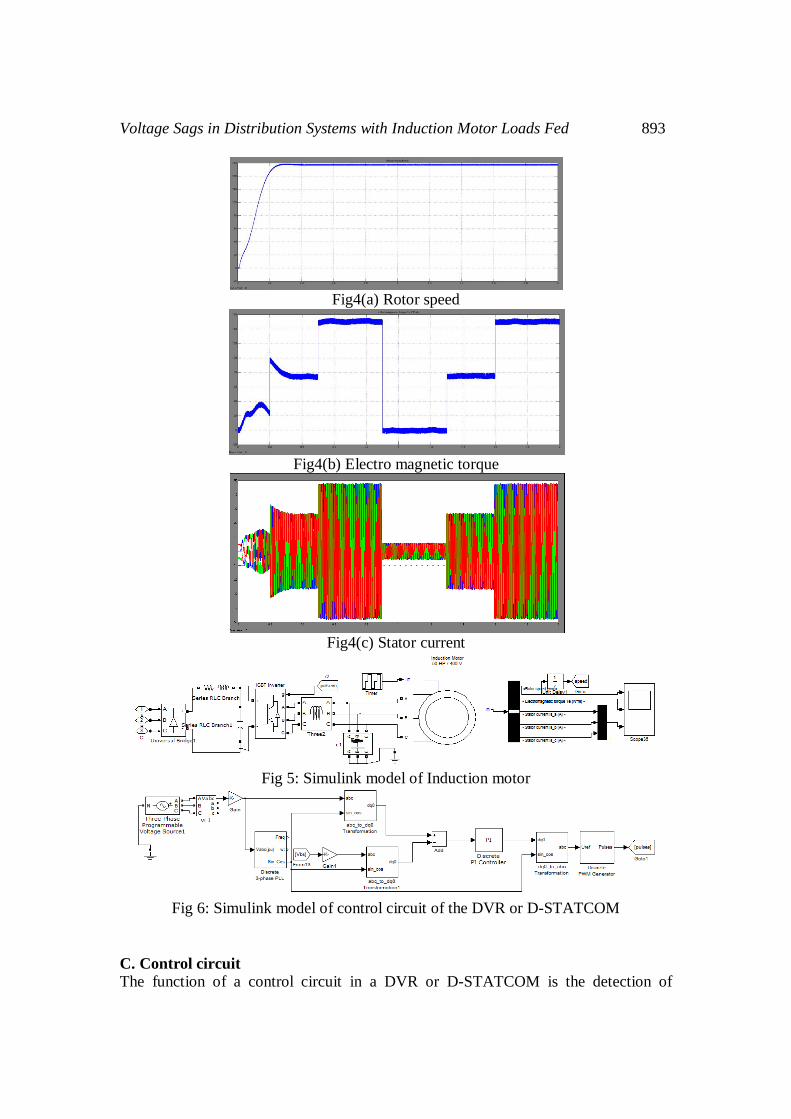
B. Induction motor For the Induction motor load Figure4 shows the characteristics. The motor has the following data: 400V, 50H.P, 50Hz. No.of poles=4, X/R ratio=2.88 and Moment of Inertia J=0.05Kg/m2. where R and X is the stator resistance and reactance respectively. Figure4(a) denotes rotor speed of motor Figure4(b) electromagnetic torque for a load of intermittent period duty and Figure4(c) of induction motor. Fig 5 shows the simulink model of induction motor.
Voltage Sags in Distribution Systems with Induction Motor Loads Fed 893
Fig4(a) Rotor speed
Fig4(b) Electro magnetic torque
Fig4(c) Stator current
Fig 5: Simulink model of Induction motor
Fig 6: Simulink model of control circuit of the DVR or D-STATCOM
C. Control circuit The function of a control circuit in a DVR or D-STATCOM is the detection of
894 P.N.K. Sreelatha et al
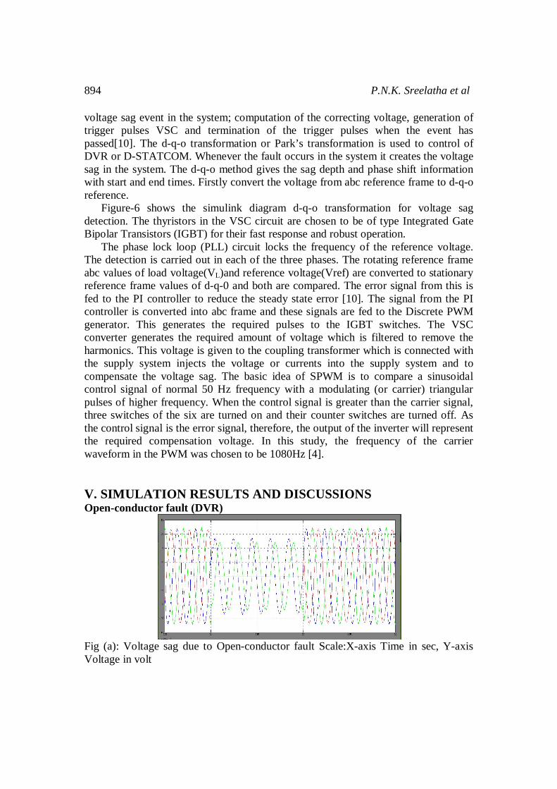
voltage sag event in the system; computation of the correcting voltage, generation of trigger pulses VSC and termination of the trigger pulses when the event has passed[10]. The d-q-o transformation or Park’s transformation is used to control of DVR or D-STATCOM. Whenever the fault occurs in the system it creates the voltage sag in the system. The d-q-o method gives the sag depth and phase shift information with start and end times. Firstly convert the voltage from abc reference frame to d-q-o reference. Figure-6 shows the simulink diagram d-q-o transformation for voltage sag detection. The thyristors in the VSC circuit are chosen to be of type Integrated Gate Bipolar Transistors (IGBT) for their fast response and robust operation. The phase lock loop (PLL) circuit locks the frequency of the reference voltage. The detection is carried out in each of the three phases. The rotating reference frame abc values of load voltage(VL)and reference voltage(Vref) are converted to stationary reference frame values of d-q-0 and both are compared. The error signal from this is fed to the PI controller to reduce the steady state error [10]. The signal from the PI controller is converted into abc frame and these signals are fed to the Discrete PWM generator. This generates the required pulses to the IGBT switches. The VSC converter generates the required amount of voltage which is filtered to remove the harmonics. This voltage is given to the coupling transformer which is connected with the supply system injects the voltage or currents into the supply system and to compensate the voltage sag. The basic idea of SPWM is to compare a sinusoidal control signal of normal 50 Hz frequency with a modulating (or carrier) triangular pulses of higher frequency. When the control signal is greater than the carrier signal, three switches of the six are turned on and their counter switches are turned off. As the control signal is the error signal, therefore, the output of the inverter will represent the required compensation voltage. In this study, the frequency of the carrier waveform in the PWM was chosen to be 1080Hz [4]. V. SIMULATION RESULTS AND DISCUSSIONS Open-conductor fault (DVR)
Fig (a): Voltage sag due to Open-conductor fault Scale:X-axis Time in sec, Y-axis Voltage in volt
Voltage Sags in Distribution Systems with Induction Motor Loads Fed 895
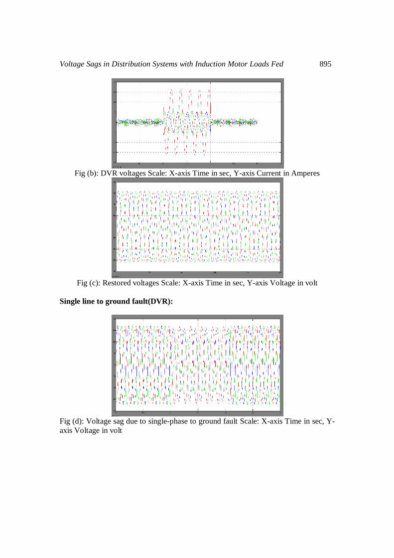
Fig (b): DVR voltages Scale: X-axis Time in sec, Y-axis Current in Amperes
Fig (c): Restored voltages Scale: X-axis Time in sec, Y-axis Voltage in volt
Single line to ground fault(DVR):
Fig (d): Voltage sag due to single-phase to ground fault Scale: X-axis Time in sec, Y-axis Voltage in volt
896 P.N.K. Sreelatha et al
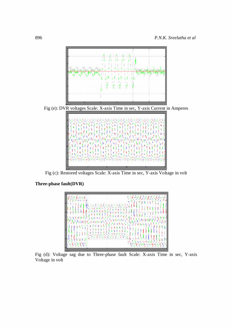
Fig (e): DVR voltages Scale: X-axis Time in sec, Y-axis Current in Amperes
Fig (c): Restored voltages Scale: X-axis Time in sec, Y-axis Voltage in volt
Three-phase fault(DVR)
Fig (d): Voltage sag due to Three-phase fault Scale: X-axis Time in sec, Y-axis Voltage in volt
Voltage Sags in Distribution Systems with Induction Motor Loads Fed 897
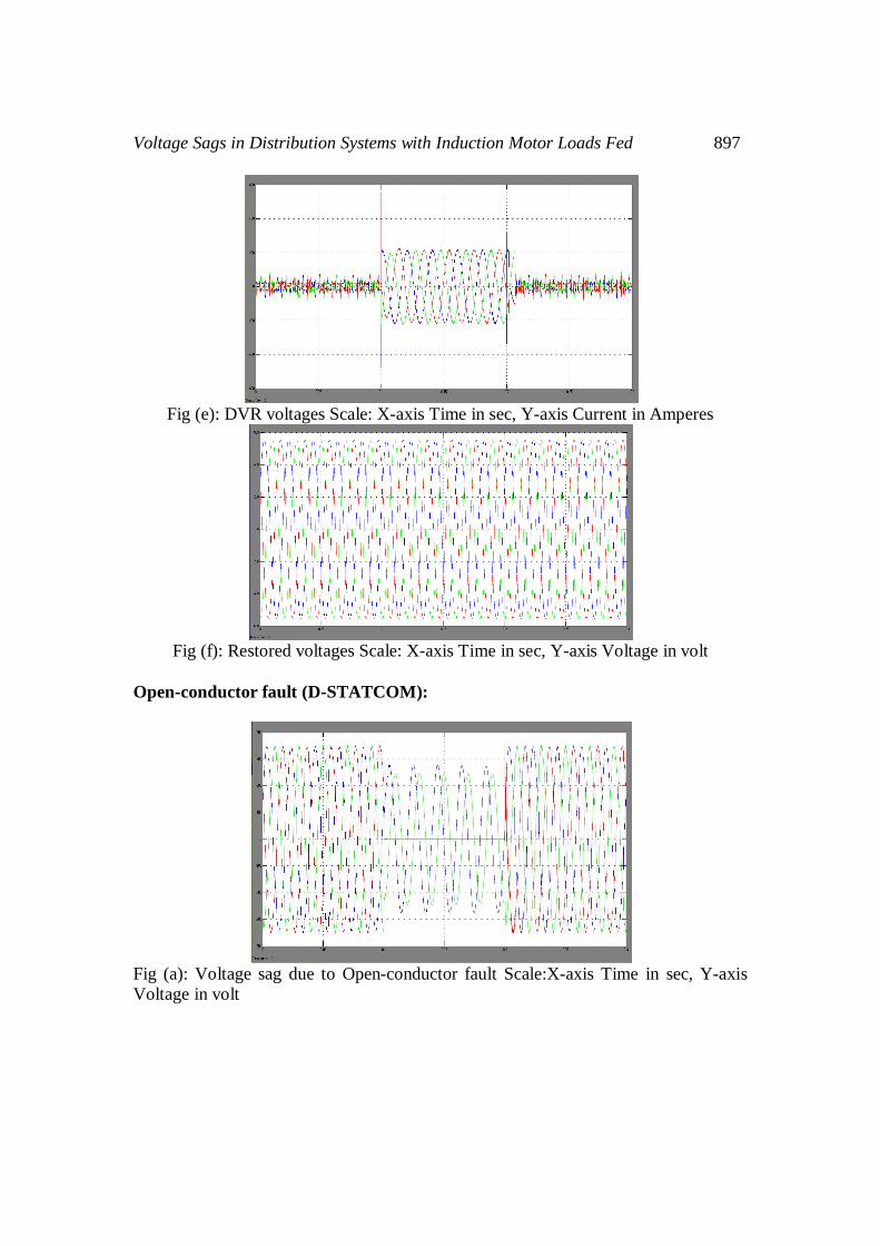
Fig (e): DVR voltages Scale: X-axis Time in sec, Y-axis Current in Amperes
Fig (f): Restored voltages Scale: X-axis Time in sec, Y-axis Voltage in volt
Open-conductor fault (D-STATCOM):
Fig (a): Voltage sag due to Open-conductor fault Scale:X-axis Time in sec, Y-axis Voltage in volt
898 P.N.K. Sreelatha et al
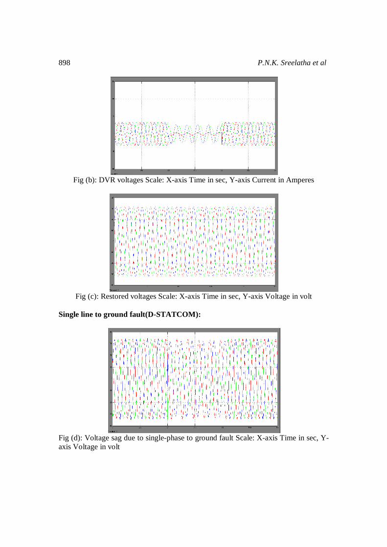
Fig (b): DVR voltages Scale: X-axis Time in sec, Y-axis Current in Amperes
Fig (c): Restored voltages Scale: X-axis Time in sec, Y-axis Voltage in volt
Single line to ground fault(D-STATCOM):
Fig (d): Voltage sag due to single-phase to ground fault Scale: X-axis Time in sec, Y-axis Voltage in volt
Voltage Sags in Distribution Systems with Induction Motor Loads Fed 899
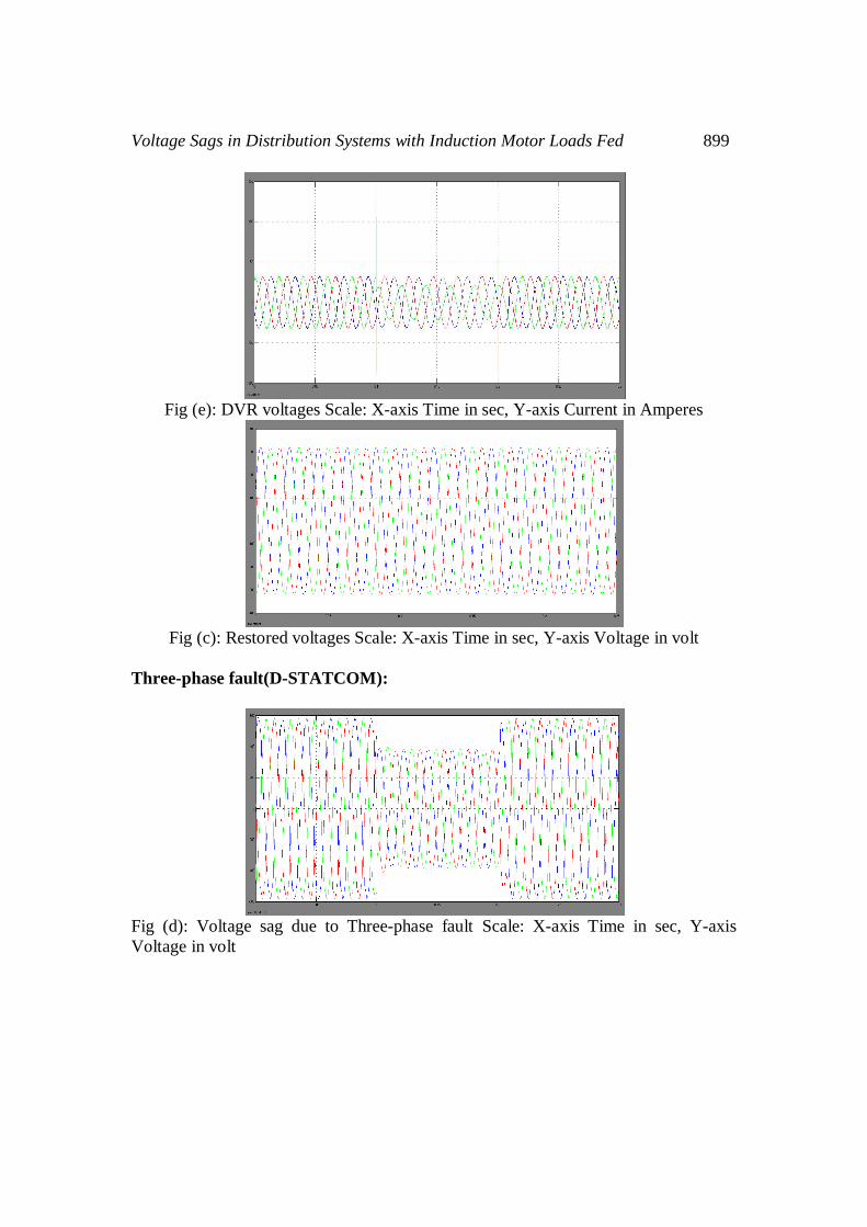
Fig (e): DVR voltages Scale: X-axis Time in sec, Y-axis Current in Amperes
Fig (c): Restored voltages Scale: X-axis Time in sec, Y-axis Voltage in volt
Three-phase fault(D-STATCOM):
Fig (d): Voltage sag due to Three-phase fault Scale: X-axis Time in sec, Y-axis Voltage in volt
900 P.N.K. Sreelatha et al
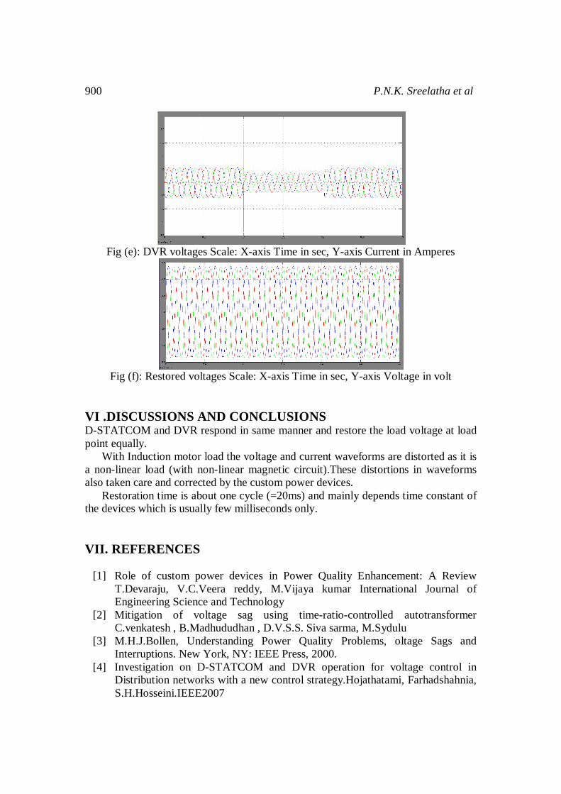
Fig (e): DVR voltages Scale: X-axis Time in sec, Y-axis Current in Amperes
Fig (f): Restored voltages Scale: X-axis Time in sec, Y-axis Voltage in volt
VI .DISCUSSIONS AND CONCLUSIONS D-STATCOM and DVR respond in same manner and restore the load voltage at load point equally. With Induction motor load the voltage and current waveforms are distorted as it is a non-linear load (with non-linear magnetic circuit).These distortions in waveforms also taken care and corrected by the custom power devices. Restoration time is about one cycle (=20ms) and mainly depends time constant of the devices which is usually few milliseconds only. VII. REFERENCES
[1] Role of custom power devices in Power Quality Enhancement: A Review T.Devaraju, V.C.Veera reddy, M.Vijaya kumar International Journal of Engineering Science and Technology
[2] Mitigation of voltage sag using time-ratio-controlled autotransformer C.venkatesh , B.Madhududhan , D.V.S.S. Siva sarma, M.Sydulu
[3] M.H.J.Bollen, Understanding Power Quality Problems, oltage Sags and Interruptions. New York, NY: IEEE Press, 2000.
[4] Investigation on D-STATCOM and DVR operation for voltage control in Distribution networks with a new control strategy.Hojathatami, Farhadshahnia, S.H.Hosseini.IEEE2007
Voltage Sags in Distribution Systems with Induction Motor Loads Fed 901
[5] Compensation of distribution system voltage sag by DVR and D-STATCOM. M.H.Haque 2001IEEE Porto Power Tech Conference, Portugal.
[6] Weissbach, R.S., Karady, G.G. and Farmer, R.G., “Dynamic voltage compensation on distribution feeders using flywheel energy storage”, IEEE Trans.on PD, Vol. 14, No. 2, 1999, pp. 465-471.
[7] Choi, S.S., Li, B.H. and Vilathgamuwa, “Dynamic voltage restorer with minimum energy injection”, IEEE Trans. on Power Systems, Vol. 15, No.1, 2000, pp.51-57.
[8] IEEE TRANSACTIONS ON POWER APPARATUS AND SYSTEMS NOVEMBER/DECEMBER 1970Digital simulation of simultaneous unbalances INVOLVING OPEN AND FAULTED CONDUCTORS D.R. Smith Westinghouse Electric Corporation East Pittsburgh, Pennsylvania
[9] Detection of Open-circuit Fault in 11kV Ring Circuits by Unbalanced Current Measurement H. K. Wong, Shihe Chen, S. K. Lau, JoeTang, K.P.Liu2006IEEE.
[10] DRDO Sponsored Eighth Control Instrumentation System Conference, CISCON-2011(An international conference). Voltage sag compensation with DVR for different types of faults at a remote place on a remote feeder.P.N.K.Sreelatha, J.Praveen, V.kamaraju XI.
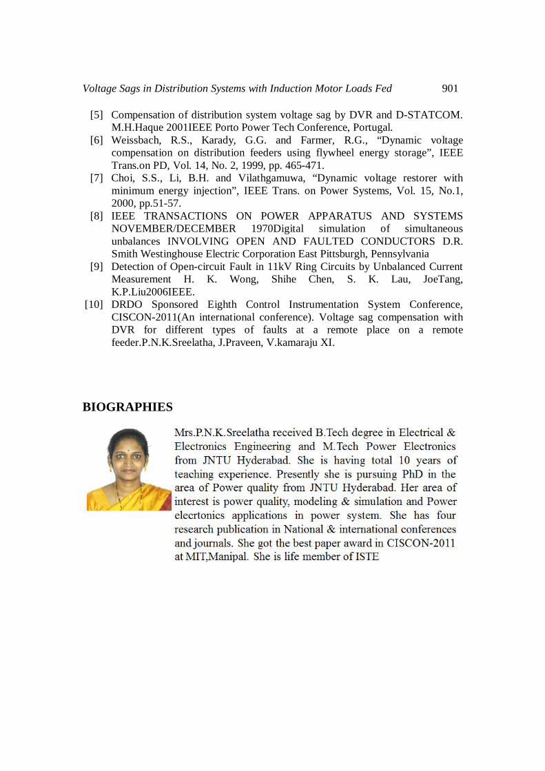
BIOGRAPHIES
902 P.N.K. Sreelatha et al