Embed Size (px)
Citation preview
This article was downloaded by: [Kungliga Tekniska Hogskola]On: 07 October 2014, At: 06:57Publisher: Taylor & FrancisInforma Ltd Registered in England and Wales Registered Number: 1072954 Registered office: Mortimer House,37-41 Mortimer Street, London W1T 3JH, UK
Chemical Engineering CommunicationsPublication details, including instructions for authors and subscription information:http://www.tandfonline.com/loi/gcec20
VOLTAGE-MEDIATED CONFORMATIONAL CHANGES OF APOLYELECTROLYTE IN A LINEAR ELASTIC MEMBRANEROCCO A. JERRY a & ASHIM DUTTA ba Department of Biomedical Engineering , Johns Hopkins University , 720 Rutland Avenue,Baltimore, MD, 21205b Department of Chemical Engineering , Michigan State University , 2527 EngineeringBuilding, East Lansing, MI, 48824Published online: 30 Mar 2007.
To cite this article: ROCCO A. JERRY & ASHIM DUTTA (1998) VOLTAGE-MEDIATED CONFORMATIONAL CHANGES OFA POLYELECTROLYTE IN A LINEAR ELASTIC MEMBRANE, Chemical Engineering Communications, 166:1, 81-110, DOI:10.1080/00986449808912382
To link to this article: http://dx.doi.org/10.1080/00986449808912382
PLEASE SCROLL DOWN FOR ARTICLE
Taylor & Francis makes every effort to ensure the accuracy of all the information (the “Content”) containedin the publications on our platform. However, Taylor & Francis, our agents, and our licensors make norepresentations or warranties whatsoever as to the accuracy, completeness, or suitability for any purpose of theContent. Any opinions and views expressed in this publication are the opinions and views of the authors, andare not the views of or endorsed by Taylor & Francis. The accuracy of the Content should not be relied upon andshould be independently verified with primary sources of information. Taylor and Francis shall not be liable forany losses, actions, claims, proceedings, demands, costs, expenses, damages, and other liabilities whatsoeveror howsoever caused arising directly or indirectly in connection with, in relation to or arising out of the use ofthe Content.
This article may be used for research, teaching, and private study purposes. Any substantial or systematicreproduction, redistribution, reselling, loan, sub-licensing, systematic supply, or distribution in anyform to anyone is expressly forbidden. Terms & Conditions of access and use can be found at http://www.tandfonline.com/page/terms-and-conditions
Chrm. Eng. Corn.. 1998, Vol. 166, pp. 81 - 110 RcprinU available directly from the publisher Photocopying permitted by l i e n s only
Q 1998 OPA (Overseas Publishen Association) Amsterdam B.V. hblishcd under l ianw
under the Gordon and Bmch Sdena Publisherr imprint.
Printcd in India.
VOLTAGE-MEDIATED CONFORMATIONAL CHANGES OF A POLYELECTROLYTE IN A LINEAR ELASTIC MEMBRANE
ROCCO A. JERRY and ASHIM DUTTA
Department of Biomedical Engineering, Johns Hopkins University, 720 Rutland Avenue, Baltimore, MD 21205;
Department of Chemical Engineering, 2527 Engineering Building, Michigan Slate University, East Lansing, MI 48824
(Received 22 April 1997: In final form 30 September 1997)
The wall of the cylindrically-shaped outer hair cell is piezoelectric, which allows the cell to function as an electromechanical transducer in the mammalian inner ear. Polyelectrolytes, which are located in the cell wall, may he responsible for the cell's piezoelectric properties. The polyelectrolytes can change conformation in response to a change in the external electric field; this conformational change can cause the cell to change its length. We have developed a model to predict the voltage response of a cylindrical cell whose wall contains conformationally- mobile polyelectrolytes. The cell wall is modeled as a rectangular lattice of polyelectrolytes connected by springs. The springs represent the (non-piezoelectric) elastic portion of the cell wall. The polyelectrolytes can exist in one of two possible conformations. The energy of the polyelectrolyte is a function of both the trans-wall electric potential difference and the forces which are applied by the surrounding elastic material in the wall. The fraction of polyelectrolytes in a given conformation is determined by the relative energies of the two conformations, by means of a Boltrmann distribution. If the electric potential difference and the pressure difference between the inside and outside of the cell are known, the model can predict the cell's radius, the length, the fraction of polyelectrolytes in a given conformation, and the electrical capacitance of the cell wall (due to the polyelectrolyte activity). We also propose an experimental scheme which would provide data that could be used to evaluate the parameters in our model. Our simulations predict that the electrical capacitance vs. voltage function should exhibit a peak which simply shifts its location (without a significant change in height) when the intracellular pressure is changed. In addition, we demonstrate that electrical stimulation of the cell, under conditions of constant cell volume, could result in a significant change in the intracellular pressure.
Keyword: Outer hair cell; linear elastic theory; stress-strain coupling; membrane tension; piezoelectric polymer films; conformational equilibrium
'Corresponding author: 808 Gabriel Court #371; Frederick, MD 21702.
8 1
Dow
nloa
ded
by [
Kun
glig
a T
ekni
ska
Hog
skol
a] a
t 06:
57 0
7 O
ctob
er 2
014
R. A. JERRY AND A. DUTTA
INTRODUCTION
Since the discovery of the piezoelectric properties of polyvinylidene fluoride (Kawai, 1969), a number of technological uses have been developed for this synthetic polymer (Chen and Payne, 1995). Polyvinylidene fluoride (PVDF) can be prepared in thin sheets, which are ideal for applications such as sound transducers (Davies et al., 1984). Its piezoelectric properties permit the material to vibrate in response to an alternating electrical field. PVDF sheets could also be used in cylindrical support beams to provide a means ofdamping vibrations in truss-typestructures (Mitchell and Reddy, 1995). They suggested that a hollow cylinder be constructed of layers of PVDF separated by layers of a non-piezoelectric material. When the cylinder is electrically stimulated, it would change its length, and do work against any load which it is supporting. This cylindrical bar could then be used, not only to support the weight of a truss, but also as an electromechanical actuator in a feedback loop, to reduce thevibrations ofa truss. In theirpaper, Mitchell and Reddy (1995)developed a theoretical model to study the behavior of such a composite cylinder.
Interestingly, some biological membranes also exhibit piezoelectric properties. For instance, the wall of the outer hair cell has been observed to be piezoelectric [see the review article by Dallos (1992) and the discussion and references in Jerry er al. (1995i, 1995ii) and Jerry and Dutta (3998i)l. The outer hair cell is located in the mammalian inner ear, and is cylindrical in shape. The cell is believed to serve as an actuator in a feedback loop; when the cell is electrically stimulated, it changes its length, and is thus able to modify the vibrational patterns of the basilar membrane [Hudspeth (1989); Dallos (1992); and references therein]. Remarkably, the cell appears to serve an identical role as the composite cylinder support beamlactuator that was proposed by Mitchell and Reddy (1995). This function of the outer hair cell is generally considered to be responsible for the sharp tuning properties and the high sensitivity of mammalian hearing (Hudspeth, 1989).
The piezoelectric properties of the outer hair cell are generally believed to be produced by polyelectrolytes that lie in the cylindrical wall of the cell [Ashmore (1987); Holley and Ashmore (1990)l. The polyelectrolytes are surrounded by non-piezoelectric elastic material in the cell wall. A change in the magnitude of the electric field should cause the .polyelectrolytes to change their conformation, and result in a change in length of the cell [Ashmore (1987); Dallos et al. (1993); Iwasa (1994)l. Thus, the celiwall serves two purposes: it acts as a barrier between the fluid inside and outside the cell, and it also contains the polyelectrolytes which are responsible for the length modulation of the cell.
Dow
nloa
ded
by [
Kun
glig
a T
ekni
ska
Hog
skol
a] a
t 06:
57 0
7 O
ctob
er 2
014
VOLTAGE-MEDIATED CONFORMATIONAL CHANGES 83
In this paper, we develop a model which specifically includes the polyelectrolytes as well as the surrounding elastic, non-piezoelectric material in the cell wall. Our model is discrete; the polyelectrolytes are assumed to be uniformly distributed throughout the cell wall, and are connected to each other by springs which represent the non-piezoelectric material in the wall. Our model provides detailed information on how the polyelectrolytes behave. This is more information than could be obtained using a standard piezoelectric continuum model. However, as a consequence, our model also contains more parameters than a standard piezoelectric model. To compensate for this, we propose three experiments along with a protocol for evaluating many of the unknown parameters.
There are two contributions to the energy of the polyelectrolyte: one contribution arising from the tension in the cell wall and another arising from the electric field. Normally, the pressure inside the outer hair cell is higher than the external pressure; this produces tensile forces in the wall of the cell which help to maintain the shape of the cell. When the
. polyelectrolyte changes conformation, it must work against the forces due to the membrane tension. In addition, the polyelectrolyte possesses electrically-charged sites; these sites experience forces due to the presence of an externally-applied electric field. When the polyelectrolyte changes conformation, work is also involved when these charged sites move through the electric field.
An experimenter can control both factors which influence the polyelec- trolyte conformation: the electrical field and the wall'tension. The electrical field near the cell wall is typically controlled with voltage clamping techniques (Ashmore, 1987). In this procedure, an electrode is placed in contact with the intracellular fluid, and another electrode is in contact with the fluid outside the cell. The cell wall has a low electrical conductivity compared to the fluids inside and outside the cell [Loew (1993), Jerry et al. (1996)l. Therefore, it is usually assumed that the electric potential is nearly uniform in the fluid. Thus, the potential difference between the electrodes is nearly equal to the potential difference across the cell wall. Consequently, by setting the electrode potential, the experimenter can directly set the trans- wall potential difference. In addition, the experimenter also has control over the wall tension, by injecting fluid into the cell interior or withdrawing fluid, as in the experiments of Kakehata and Santos-Sacchi (1995). The cell wall behaves much in the same way as the membrane of a balloon; introducing fluid into the cell interior will increase both the intracellular pressure and the tension in the cell wall, and the reverse effect should occur if fluid is removed.
Dow
nloa
ded
by [
Kun
glig
a T
ekni
ska
Hog
skol
a] a
t 06:
57 0
7 O
ctob
er 2
014
84 R. A. JERRY AND A. DUTTA
We assume that the polyelectrolyte can exist in only two different conformations. Each conformation has an energy associated with it. This energy is affected by both the wall tension and the trans-wall potential difference. It is assumed that the number of polyelectrolytes in each conformation obeys a Boltzmann distribution, based on the energy of that particular conformation. Dallos et al. (1993) had also developed a model of the outer hair cell wall which contained polyelectrolytes connected by springs. However, two important considerations were omitted. First, the effect of tension on the polyelectrolyte energy was assumed to be negligible. Thus, their model does not include the tension-voltage coupling. Second, their linear theory for the (non-piezoelectric) elastic portion of the cell wall does not contain the cross-coupling between the strain in one direction and the tension in the opposite direction. This coupling is significant for most real materials. As we show later in this paper, a'model which fails to include this cross-coupling will not predict the correct direction of the dimensional changes for the cell. [The Dallos et al. (1993) model predicts that the cell should shorten when the intracellular pressure is reduced, contrary to the experimental observations of Kakehata and Santos-Sacchi (1995) and others]. Our model includes both the tension dependence in the polyelec- trolyte energy expression, as well as the cross-coupling in the linear theory for the elastic portion of the cell wall.
Continuum piezoelectric models for solid cylinders have been developed by Adelman et al. (1975). Hollow cylinders containing alternating layers of piezoelectric and non-piezoelectric materials were modeled by Mitchell and Reddy (1995). Their model assumes that the pressure in the hollow space is identical to the pressure outside the cylinder. Thus, pressure coupling effects were not induded in their model. The influence of intracellular pressure is known to be important for the outer hair cell (Kakehata and Santos-Sacchi, 1995). The effects of pressure on piezoelectric membranes have been investigated both theoretically and experimentally by Davies et al. (1984) and Abram (1980i, 1980ii, 1980iii); these reports deal with a patch of a piezoelectric membrane.
Iwasa (1994) developed an hybrid continuum-discrete model for the outer hair cell; the elastic portion of the cell wall was described by a continuum theory, and the polyelectrolytes were treated as individual entities. In his paper, the polyelectrolytes were said to have the same elastic properties as the non-piezoelectric portion of the cell wall. However, in his energy expression, he had assumed that the polyelectrolyte was perfectly rigid. This inconsistency is caused by the combination of a continuum representation of the elastic portion of the cell wall, with the discrete representation of the
Dow
nloa
ded
by [
Kun
glig
a T
ekni
ska
Hog
skol
a] a
t 06:
57 0
7 O
ctob
er 2
014
VOLTAGE-MEDIATED CONFORMATIONAL CHANGES 85
polyelectrolyte. As a result, many of the Iwasa (1994) model parameters are difficult to clearly define. The problem could be avoided either by using a model that is entirely continuous, such as the standard model for a piezoelectric material [used by Mitchell and Reddy (1995) among others], or by using a model that is entirely discrete. Our model uses a discrete representation for both the polyelectrolytes and the elastic material in the wall, and extends the Dallos et al. (1993) treatment by including both the cross-coupling and the tension-dependence of the energy. We have used our model to investigate the load-carrying properties of the outer hair cell in Jerry and Dutta (1998ii).
THE MODEL
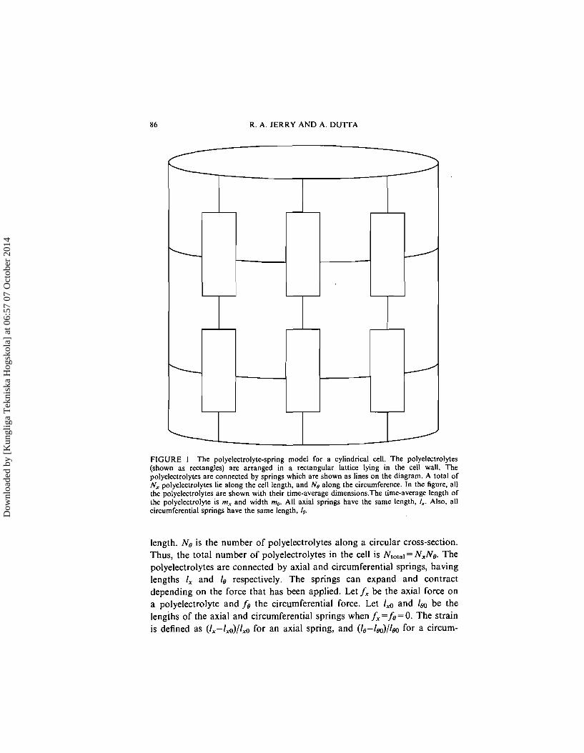
The model consists of polyelectrolytes connected by springs, that form the cylindrical wall of the cell, and are attached to one another as shown in Figure 1. In our model, the cell wall consists of three regions: the central cylindrical portion, and two flat portions which close the cell at the ends. There are no polyelectrolytes in the flat ends of the cell. We assume that the walls are non-porous; there is no exchange of fluid between the intracellular and extracellular regions.
Each polyelectrolyte is assumed to exist in one of two different geometric conformations (states) which we designate as C and W. The polyelectrolyte in each state is assumed to be rectangular in shape. The dimensions of the rectangle for the C and W states differ. In state C, the polyelectrolyte has an axial length c, and circumferential length co. In state W, the axial and circumferential lengths are w, and wo, respectively. Thus, the difference in areal surface coverage of the two states can be written: Iw,wo - c,ce). Note that the two states may have different dimensions, yet still could be equal in surface coverage. For example, one could select parameter values such that w,xwo = c,xco. In such a case, the areal surface coverage would be the same for both states.
We assume that the magnitudes of these four parameters are all independent of wall tension. In other words, the dimensions of the polyelectrolyte in state C, as well as in state W, are unaffected by the magnitude of the wall tension. The wall tension affects the energy of each state, but not the dimensions of the state. We define the height of the polyelectrolyte as its dimension in the axial direction, and the width of the polyelectrolyte as the dimension in the circumferential direction. As shown in Figure 1, N, is the number of polyelectrolytes stacked along the cell's
Dow
nloa
ded
by [
Kun
glig
a T
ekni
ska
Hog
skol
a] a
t 06:
57 0
7 O
ctob
er 2
014
R. A. JERRY AND A. DUTTA
FIGURE I The polyelectrolyte-spring model for a cylindrical cell. The polyelectrolytes (shown as rectangles) are arranged in a rectangular lattice lying in the cell wall. The polyelectrolytes are connected by springs which are shown as lines on the diagram. A total of N, polyelectrolytes lie along the cell length, and Ne along the circumference. In the figure, all the polyelectrolytes are shown with their time-average dimensions.The time-average length of the polyelectrolyte is m, and width me. All axial springs have the same length, I,. Also, all circumferential springs have the same length, 10.
length. No is the number of polyelectrolytes along a circular cross-section. Thus, the total number of polyelectrolytes in the cell is Ntotal= N,Ne. The polyelectrolytes are connected by axial and circumferential springs, having lengths I, and Is respectively. The springs can expand and contract depending on the force that has been applied. Let fx be the axial force on a polyelectrolyte and fe the circumferential force. Let lfl and lm be the lengths of the axial and circumferential springs when fx=fs=O. The strain is defined as (1,-lfi)/lA for an axial spring, and (Is-lm)/lm for a circum-
Dow
nloa
ded
by [
Kun
glig
a T
ekni
ska
Hog
skol
a] a
t 06:
57 0
7 O
ctob
er 2
014
VOLTAGE-MEDIATED CONFORMATIONAL CHANGES 87
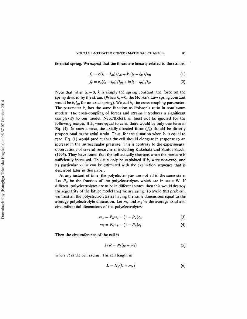
ferential spring. We expect that the forces are linearly related to the strains:
Note that when k,=O, k is simply the spring constant: the force on the spring divided by the strain. (When k,=O, the Hooke's Law spring constant would be k/ld for an axial spring). We call k, the cross-coupling parameter. The parameter kc has the same function as Poisson's ratio in continuum models. The cross-coupling of forces and strains introduces a significant complexity to our model. Nevertheless, k, must not be ignored for the following reason. If kc were equal to zero, there would be only one term in Eq. (I). In such a case, the axially-directed force (A) should be directly proportional to the axial strain. Thus, for the situation when kc is equal to zero, Eq. ( I ) would predict that the cell should elongate in response to an increase in the intracellualar pressure. This is contrary to the experimental observations of several researchers, including Kakehata and Santos-Sacchi (1995). They have found that the cell actually shortens when the pressure is sufficiently increased. This can only be explained if kc were non-zero, and its particular value can be estimated with the evaluation sequence that is described later in this paper.
At any instant of time, the polyelectrolytes are not all in the same state. Let P, be the fraction of the polyelectrolytes which are in state W. If different polyelectrolytes are to be in different states, then this would destroy the regularity of the lattice model that we are using. To avoid this problem, we treat all the polyelectrolytes as having the same dimensions equal to the average polyelectrolyte dimension. Let m, and me be the average axial and circumferential dimensions of the polyelectrolytes:
Then the circumference of the cell is
where R is the cell radius. The cell length is
Dow
nloa
ded
by [
Kun
glig
a T
ekni
ska
Hog
skol
a] a
t 06:
57 0
7 O
ctob
er 2
014
88 R. A. JERRY AND A. DU'ITA
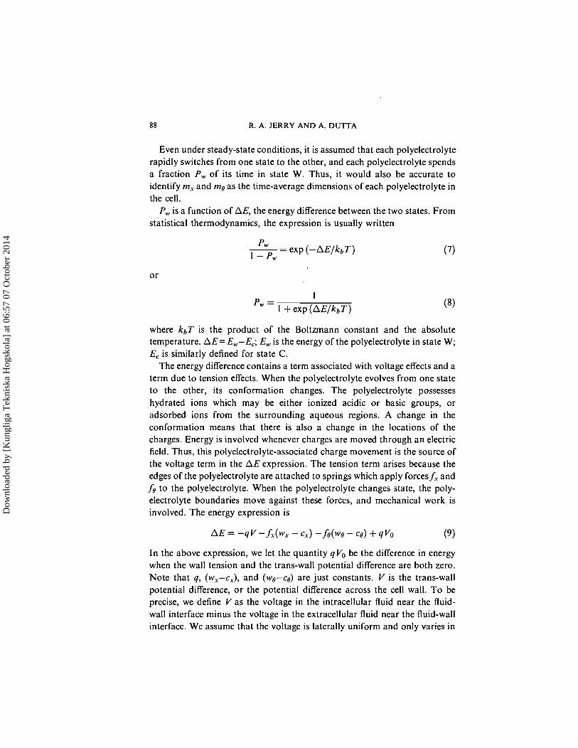
Even under steady-state conditions, it is assumed that each polyelectrolyte rapidly switches from one state to the other, and each polyelectrolyte spends a fraction P , of its time in state W. Thus, it would also be accurate to identify m, and me as the time-average dimensions of each polyelectrolyte in the cell.
P,, is a function of AE, the energy difference between the two states. From statistical thermodynamics, the expression is usually written
-- Pw - exp ( - A E / k b T ) 1 - P,
P - 1
" - 1 + exp ( A E / k b T )
where kbT is the product of the Boltzmann constant and the absolute temperature. A E = E,-E,; E, is the energy of the polyelectrolyte in state W; E, is similarly defined for state C.
The energy difference contains a term associated with voltage effects and a term due to tension effects. When the polyelectrolyte evolves from one state to the other, its conformation changes. The polyelectrolyte possesses hydrated ions which may be either ionized acidic or basic groups, or adsorbed ions from the surrounding aqueous regions. A change in the conformation means that there is also a change in the locations of the charges. Energy is involved whenever charges are moved through an electric field. Thus, this polyelectrolyte-associated charge movement is the source of the voltage term in the A E expression. The tension term arises because the edges of the polyelectrolyte are attached to springs which apply forces f, and fe to the polyelectrolyte. When the polyelectrolyte changes state, the poly- electrolyte boundaries move against these forces, and mechanical work is involved. The energy expression is
In the above expression, we let the quantity qVo be the difference in energy when the wall tension and the trans-wall potential difference are both zero. Note that q , (wx-ex), and (we-ce) are just constants. V is the trans-wall potential difference, or the potential difference across the cell wall. To be precise, we define V as the voltage in the intracellular fluid near the fluid- wall interface minus the voltage in the extracellular fluid near the fluid-wall interface. We assume that the voltage is laterally uniform and only varies in
Dow
nloa
ded
by [
Kun
glig
a T
ekni
ska
Hog
skol
a] a
t 06:
57 0
7 O
ctob
er 2
014
VOLTAGE-MEDIATED CONFORMATIONAL CHANGES 89
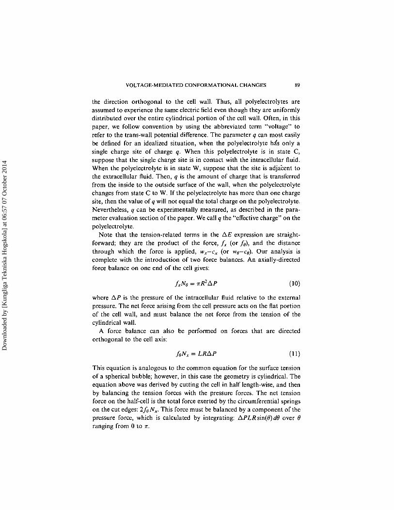
the direction orthogonal to the cell wall. Thus, all polyelectrolytes are assumed to experience the same electric field even though they are uniformly distributed over the entire cylindrical portion of the cell wall. Often, in this paper, we follow convention by using the abbreviated term "voltage" to refer to the trans-wall potential difference. The parameter q can most easily be defined for an idealized situation, when the polyelectrolyte hds only a single charge site of charge q. When this polyelectrolyte is in state C, suppose that the single charge site is in contact with the intracellular fluid. When the polyelectrolyte is in state W, suppose that the site is adja-cent to the extracellular fluid. Then, q is the amount of charge that is transferred from the inside to the outside surface of the wall, when the polyelectrolyte changes from state C to W. If the polyelectrolyte has more than one charge site, then the value of q will not equal the total charge on the polyelectrolyte. Nevertheless, q can be experimentally measured, as described in the para- meter evaluation section of the paper. We call q the "effective charge" on the polyelectrolyte.
Note that the tension-related terms in the A E expression are straight- forward; they are the product of the force, f, (or fa), and the distance through which the force is applied, w,-c, (or we-cs). Our analysis is complete with the introduction of two force balances. An axially-directed force balance on one end of the cell gives:
where A P is the pressure of the intracellular fluid relative to the external pressure. The net force arising from the cell pressure acts on the flat portion of the cell wall, and must balance the net force from the tension of the cylindrical wall.
A force balance can also be performed on forces that are directed orthogonal to the cell axis:
This equation is analogous to the common equation for the surface tension of a spherical bubble; however, in this case the geometry is cylindrical. The equation above was derived by cutting the cell in half length-wise, and then by balancing the tension forces with the pressure forces. The net tension force on the half-cell is the total force exerted by the circumferential springs on the cut edges: 2 fa N,. This force must be balanced by a component of the pressure force, which is calculated by integrating: APLR sin(@) dB over 0 ranging from 0 to T.
Dow
nloa
ded
by [
Kun
glig
a T
ekni
ska
Hog
skol
a] a
t 06:
57 0
7 O
ctob
er 2
014
90 R. A. JERRY AND A. DUTTA
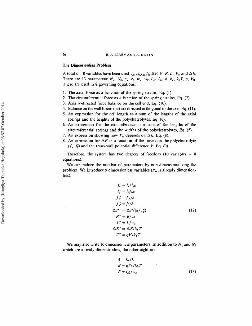
The Dimensionless Problem
A total of 10 variables have been used: I,, Is, fx , fs , A P , V, R, L , P , and AE. There are 13 parameters: N,, No, ex, ce, w,, we, Id, I,, k , kc, kbT, q, Vo. These are used in 8 governing equations:
1 . The axial force as a function of the spring strains, Eq. (I). 2. The circumferential force as a function of the spring strains, Eq. (2). 3. Axially-directed force balance on the cell end, Eq. (10). 4. Balance on the wall forces that are directed orthogonal to the axis, Eq. (1 1). 5. An expression for the cell length as a sum of the lengths of the axial
springs and the heights of the polyelectrolytes, Eq. (6). 6. An expression for the circumference as a sum of the lengths of the
circumferential springs and the widths of the polyelectrolytes, Eq. (5). 7. An expression showing how P , depends on AE, Eq. (8). 8 . An expression for A E as a function of the forces on the polyelectrolyte
V;, fs) and the trans-wall potential difference V, Eq. (9).
Therefore, the system has two degrees of freedom (10 variables - 8 equations).
We can reduce the number of parameters by non-dimensionalizing the problem. We introduce 9 dimensionless variables ( P , is already dimension- less).
1; = I , / / & 1; = le/lm
f: = f x P
f ; = h l k A P * = A P / ( ~ / C ; )
R * = R/cs L* = L/wx
AE* = AE/kbT V* = qV/kbT
We may also write 10 dimensionless parameters. In addition to N, and Ne which are already dimensionless, the other eight are
Dow
nloa
ded
by [
Kun
glig
a T
ekni
ska
Hog
skol
a] a
t 06:
57 0
7 O
ctob
er 2
014
VOLTAGE-MEDIATED CONFORMATlONAL CHANGES 9 1
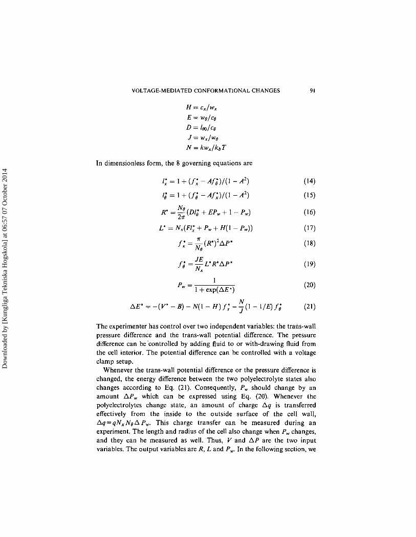
In dimensionless form, the 8 governing equations are
The experimenter has control over two independent variables: the trails-wall pressure difference and the trans-wall potential difference. The pressure difference can be 'controlled by adding fluid to or with-drawing fluid from the cell interior. The potential difference can be controlled with a voltage clamp setup.
Whenever the trans-wall potential difference or the pressure difference is changed, the energy difference between the two polyelectrolyte states also changes according to Eq. (21). Consequently, P , should change by an amount A P , which can be expressed using Eq. (20). Whenever the polyelectrolytes change state, an amount of charge A q is transferred effectively from the inside to the outside surface of the cell wall, A q = q N x N o A P w . This charge transfer can be measured during an experiment. The length and radius of the cell also change when P , changes, and they can be measured as well. Thus, V and A P are the two input variables. The output variables are R, L and P,. In the following section, we
Dow
nloa
ded
by [
Kun
glig
a T
ekni
ska
Hog
skol
a] a
t 06:
57 0
7 O
ctob
er 2
014
92 R. A. JERRY AND A. D U I T A
describe the numerical procedure that we used to calculate R, L and P , from the input variables (V and AP).
NUMERICAL APPROACH
For now, we assume that all 13 parameters are known a priori. In a later section, we will describe particular experiments necessary in order to evaluate these parameters.
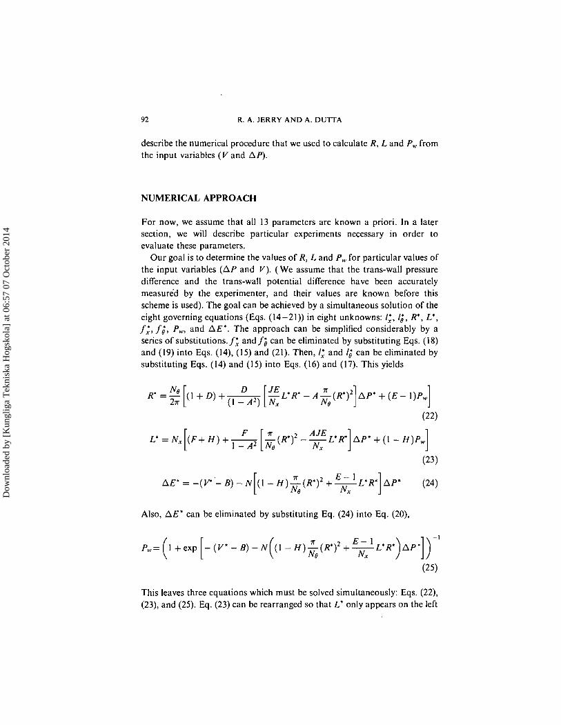
Our goal is to determine the values of R, L and P, for particular values of the input variables ( A P and V). ( W e assume that the trans-wall pressure difference and the trans-wall potential difference have been accurately measured by the experimenter, and their values are known before this scheme is used). The goal can be achieved by a simultaneous solution of the eight governing equations (Eqs. (14-21)) in eight unknowns: I:, I,', R', L*, f,', fi, P,, and AE'. The approach can be simplified considerably by a series ofsubstitutions. f; and f$ can be eliminated by substituting Eqs. (18) and (19) into Eqs. (14), (15) and (21). Then, 1; and I,' can be eliminated by substituting Eqs. (14) and (15) into Eqs. (16) and (17). This yields
( F + H ) + - -(R*12 --L'R* A P * + ( I - H)P, Nx 1 1
Also, A E * can be eliminated by substituting Eq. (24) into Eq. (20),
This leaves three equations which must be solved simultaneously: Eqs. (22), (23), and (25). Eq. (23) can be rearranged so that L* only appears on the left
Dow
nloa
ded
by [
Kun
glig
a T
ekni
ska
Hog
skol
a] a
t 06:
57 0
7 O
ctob
er 2
014
VOLTAGE-MEDIATED CONFORMATIONAL CHANGES 93
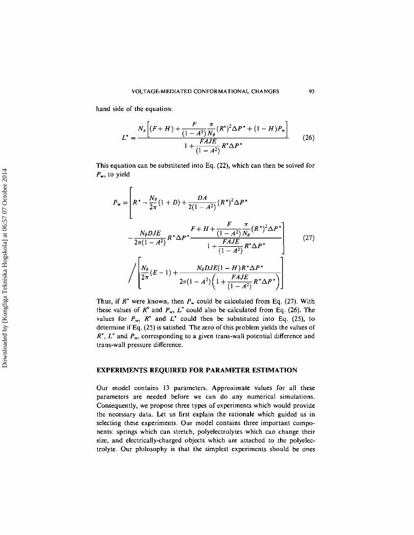
hand side of the equation:
This equation can be substituted into Eq. (22), which can then be solved for P,, to yield
Thus, if R* were known, then P, could be calculated from Eq. (27). With these values of R* and P,, L* could also be calculated from Eq. (26). The values for P,, R* and L' could then be substituted into Eq. (25), to determine if Eq. (25) is satisfied. The zero of this problem yields the values of R*, L* and P,,,, corresponding to a given trans-wall potential difference and trans-wall pressure difference.
EXPERIMENTS REQUIRED FOR PARAMETER ESTIMATION
Our model contains 13 parameters. Approximate values for all these parameters are needed before we can do any numerical simulations. Consequently, we propose three types of experiments which would provide the necessary data. Let us first explain the rationale which guided us in selecting these experiments. Our model contains three important compo- nents: springs which can stretch, polyelectrolytes which can change their size, and electrically-charged objects which are attached to the polyelec- trolyte. Our philosophy is that the simplest experiments should be ones
Dow
nloa
ded
by [
Kun
glig
a T
ekni
ska
Hog
skol
a] a
t 06:
57 0
7 O
ctob
er 2
014
94. R. A. JERRY AND A. DUTTA
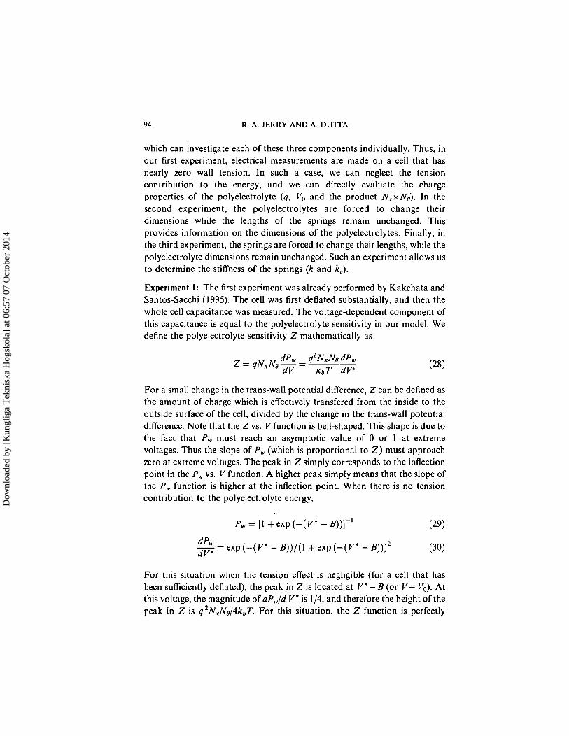
which can investigate each of these three components individually. Thus, in our first experiment, electrical measurements are made on a cell that has nearly zero wall tension. In such a case, we can neglect the tension contribution to the energy, and we can directly evaluate the charge properties of the polyelectrolyte (q, Vo and the product NxxN6). In the second experiment, the polyelectrolytes are forced to change their dimensions while the lengths of the springs remain unchanged. This provides information on the dimensions of the polyelectrolytes. Finally, in the third experiment, the springs are forced to change their lengths, while the polyelectrolyte dimensions remain unchanged. Such an experiment allows us to determine the stiffness of the springs (k and k3.
Experiment 1: The first experiment was already performed by Kakehata and Santos-Sacchi (1995). The cell was first deflated substantially, and then the whole cell capacitance was measured. The voltage-dependent component of this capacitance is equal to the polyelectrolyte sensitivity in our model. We define the polyelectrolyte sensitivity Z mathematically as
For a small change in the trans-wall potential difference, Z can be defined as the amount of charge which is effectively transfered from the inside to the outside surface of the cell, divided by the change in the trans-wall potential difference. Note that the Z vs. V function is bell-shaped. This shape is due to the fact that P, must reach an asymptotic value of 0 or 1 a t extreme voltages. Thus the slope of P , (which is proportional to 2) must approach zero a t extreme voltages. The peak in Z simply corresponds to the inflection point in the P,, vs. V function. A higher peak simply means that the slope of the P,. function is higher at the inflection point. When there is no tension contribution to the polyelectrolyte energy,
Pw = [ I + exp ( - ( Y e - B) ) ] - ' (29)
-- dPw - exp ( - (v* - B ) ) / ( I + exp ( - (v* - B ) ) ) ~ d V *
For this situation when the tension effect is negligible (for a cell that has been sufficiently deflated), the peak in Z is located a t V * = B (or V = Vo). At this voltage, the magnitude of dP,/d V * is 114, and therefore the height of the peak in Z is q2N,N8/4kh~. For this situation, the Z function is perfectly
Dow
nloa
ded
by [
Kun
glig
a T
ekni
ska
Hog
skol
a] a
t 06:
57 0
7 O
ctob
er 2
014
VOLTAGE-MEDIATED CONFORMATIONAL CHANGES 95
symmetric about the peak. In terms of the original dimensional para- meters, Z is
where
Kakehata and Santos-Sacchi (1995) fitted their data for a nearly completely deflated cell to Eq. (3 l), and reported = - 1.3 x Coul, Nto,,I = Nxx No = 2.3 x lo7, and Vo = -70 mV. NtOtaI is the total number of polyelectrolytes in the cell. These numbers may be determined from the information in the caption of their Figure 3.
Experiment 2: The second experiment also involves a cell that has been sufficiently deflated. In this case, the radius and length of the cell must be measured for a very large positive and a large negative value of V. The extreme values of V are necessary so that all the polyelectrolytes are in the same state (either all C or all W ) when the radius and length are measured. Note that the springs will all have their tension-free lengths (Id for axial springs and leo for circumferential springs), because the cell has been sufficiently deflated.
Let us define R, and LC as the dimensions of the nearly deflated cell when all the polyelectrolytes are in state C. Similar definitions hold for R, and L, when all the polyelectrolytes are in state W. Then we can write four equations:
These four equations can be rearranged into a set of four more useful equations. After introducing some dimensionless parameters:
Dow
nloa
ded
by [
Kun
glig
a T
ekni
ska
Hog
skol
a] a
t 06:
57 0
7 O
ctob
er 2
014
R. A. JERRY AND A. DUTTA
These equations will be used in the parameter estimation procedure.
Experiment 3: In this experiment, the springs must be stretched while the polyelectrolytes' dimensions remain unchanged. This can be achieved as follows. Voltage clamping could be used to maintain a large positive or a large negative trans-wall potential difference; this would ensure that all polyelectrolytes are in a single state (either all in "C" or all in " W ) . While this potential difference is maintained, fluid could be injected into the cell. Then, the trans-wall pressure difference could be measured along with the corresponding cell dimensions: the radius and the length. As we show below, it is possible to determine the stiffness of the springs (specifically the values of k and kc) with this experimental data. We also show later in this section that the cell must be partially deflated before fluid is injected.
In what follows, we apply our model so that we can evaluate k and kc from the experimental data. In lwasa and Chadwick (1992) fluid was injected into the cell, which caused the intracellular pressure to increase. (However, they did not clamp at an extreme voltage nor did they deflate the cell before performing the experiment). They measured the trans-wall pressure difference, and the corresponding radius and length. We define the axial strain (6L) which occurs after a certain amount of fluid has been injected into the cell.
and the circumferential strain (6R) may also be defined as:
where the subscript i refers to the initial dimensions, and f to the final dimensions after the volume change. In order to determine how much the dimensions change when the trans-wall pressure difference is changed, we require Eqs. (14- 19). These equations may be written as:
Dow
nloa
ded
by [
Kun
glig
a T
ekni
ska
Hog
skol
a] a
t 06:
57 0
7 O
ctob
er 2
014
VOLTAGE-MEDIATED CONFORMATIONAL CHANGES 97
The terms 7, and 72 are the contributions of the polyelectrolytes to R' and L * respectively. Both yl and 72 are functions of P,. The derivative of R* and L' with respect to AP* may be calculated
In deriving these equations, we did not include the polyelectrolyte contri- bution. Omitting the polyelectrolyte contribution should be accurate as long as the cell is clamped at an extreme voltage during the experiment, so that the polyelectrolytes all remain in a single state.
In the analysis that follows, we will assume that the second term (the term that contains A P * ) in Eqs. (47) and (48) is small. By making this assump- tion, we are able to simplify our analysis considerably. This assumption should be valid if the cell is sufficiently deflated before fluid is injected into the cell. Deflating before fluid injection will ensure that A P is small. After rearranging and returning to dimensional form,
where
Dow
nloa
ded
by [
Kun
glig
a T
ekni
ska
Hog
skol
a] a
t 06:
57 0
7 O
ctob
er 2
014
98 R. A. JERRY AND A. D U R A
The circumferential strain dR/R is the result of the change in AP. An axial strain dL/L is also produced by this change in the trans-wall pressure difference. Thus, (dR/R)/(dAP) is just the ratio of the circumferential strain to the change in the trans-wall pressure difference. Taking the ratio of these two equations,
We can solve the equation above for A, which is just the ratio kJk,
where
The quantity rn, is measured in Experiment.2. Once A has been determined, then k can be determined by using a rearrangement of Eq. (50).
where
,From the defining equation for cr (Eq. (51)), it is obvious that a is just the ratio of the polyelectrolyte density along the circumference to the poly- electrolyte density along the length of the cell. Here, the density is defined as the number of polyelectrolytes per unit length; the polyelectrolyte density along the circumference is Ns/(2.rrR) and along the length N,/L.
Note that the polyelectrolyte dimensions are conspicuously absent from both Eqs. (53) and (56), as expected from our assumption that the poly- electrolyte activity is either zero or negligible.
The assumption that the second term in Eqs. (47) and (48) is small is very important. Thus, we will now investigate the regime over which the
Dow
nloa
ded
by [
Kun
glig
a T
ekni
ska
Hog
skol
a] a
t 06:
57 0
7 O
ctob
er 2
014
VOLTAGE-MEDIATED CONFORMATIONAL CHANGES 99
assumption should be valid. Let us define r , as the ratio of the second term to the first term in Eq. (47), and let rz be the ratio for Eq. (48). Then, we can write
where
dd l A P * - r , = d A P *
dl
If we introduce some dimensional parameters,
AnN,
RL - * R 2 ] (62) Ne
Both rl and r2 must be small in magnitude in order for our assumptions to be valid. They should be small if the cell is nearly completely deflated before fluid injection. However, the experimenter could substitute measurements into the two equations above, if he wishes to ensure that the assumptions have been satisfied.
Experiment 1 explored the electrical properties of the polyelectrolyte when it is isolated from the rest of the cell (when there is no wall tension). Experiment 2 investigated the geometric properties (the physical dimen- sions) of the polyelectrolytes and springs. Experiment 3 studied the elastic properties of the springs. In the following section, we describe how these experiments may be used to evaluate the parameters in our model.
Dow
nloa
ded
by [
Kun
glig
a T
ekni
ska
Hog
skol
a] a
t 06:
57 0
7 O
ctob
er 2
014
100 R. A. JERRY AND A. DUTTA
PARAMETER ESTIMATION TECHNIQUE
Once the data from experiments 1-3 have been collected, the following parameter evaluation technique can be used. Note that the technique below can be used to evaluate all the parameters except for N,, H and E. Values for these three quantities had to be assumed in Step 2 of the following procedure. These parameter values could be determined by devising additional experiments that could be used for curve fitting purposes.
1. Experiment 1 provides an estimate of q, V,,, and N,,,,, (which =
NxxNe), by fitting data to Eq. (31), as described in the previous section. 2. Assume values for N,, H and E. 3. Calculate No= Ntotal/N.7. 4. Experiment 2 provides a measurement of m3= LC/ L,. Eq. (37) can be
used to evaluate F : F = (m3-H)/(I - m3) 5. Experiment 2 also provides a measurement of m4 = R,/ R,. Eq. (38) can
be used to evaluate D : D = (ma-E)/(1 - m,). 6. Experiment 2 provides a measurement of L,. Eq. (39) can be used to
evaluate wx:wx = Lw/(Nx(F + I)). 7. Experiment 2 provides a measurement of R,. Eq. (40) can be used to
evaluate ce:ce = 2 rR,/(NE(D + 1)). 8. Calculate Id from: Id = F x w,. 9. Calculate cx from: c, = H x w,.
10. Calculate lm from lm = D x ce. 11. Calculate we from ws = E x ce. 12. Calculate J = wx/we. 13. Calculate B = qVo/(kbT). 14. Experiment 3 provides a measurement of ml =(dL/L)/(dR/R). Eq. (53)
can be used to evaluate A = k,/k. 15. Experiment 3 provides a measurement of m2 = (dL/L)/(dAP). Eq. (56)
can be.used to evaluate k. 16. Calculate kc= A x k . 17. Calculate N = kw,/ (kbT).
There are certain guides that could be used to aid the experimenter in selecting initial values for N,, H, and E. Obviously, N, should be selected to ,lie between 0 and N,xNe (the value of this product is known in advance from Experiment 1). Initial guesses for H (which = c,/w,) and E (which =
we/ce) can be guided based on information provided in Experiment 2. Experiment 2 provides measurements of L,, LC, R,, and R,. If L, is larger than LC, then w, must be larger than c,. Consequently, this requires that H
Dow
nloa
ded
by [
Kun
glig
a T
ekni
ska
Hog
skol
a] a
t 06:
57 0
7 O
ctob
er 2
014
VOLTAGE-MEDIATED CONFORMATIONAL CHANGES 101
be between 0 and 1. Otherwise, if L,, is less than LC, then H must be greater than 1. Similarly, if R, is larger than R,, then wo must be larger than co, and E must be greater than 1. Otherwise, it must be less than 1 .
RESULTS AND DISCUSSION
In the previous section, we prescribed experiments along with an evaluation scheme that would allow our model's parameters to be estimated. In this section, we will assume values for these parameters, so that we can demonstrate how our model and numerical scheme work. Experiment 1 was performed on a nearly deflated cell by Kakehata and Santos-Sacchi (1995), and they reported q = - 1 . 3 ~ 10-l9 Coul, N,x N0=2.3x lo7, and Vo= -70mV. We have used these values, along with LC= 61.2 microns, L,= 62 microns, R,= 3.95 microns, R,= 4.0 microns, (dL/L)/(dR/R) = -0.4, (dL/L)/dAP= -0.2 k ~ a - I , T =20"C, Nx= 5000, H=0.8, and E= 1.3. These values can be used in our parameter evaluation routine to give: cx=0.64 nm, w X = 0 . 8 n m , c o = 0 . 2 3 n m , ws=0.30nm, Ix0=11 .6nm, l m = 5 . 2 n m , kC=6.9x lo-" N, a i d k = 1 . 2 ~ N. Again, we emphasize that these parameter values were selected arbitrarily. More realistic values can be determined once Experiments 1 - 3 have been performed.
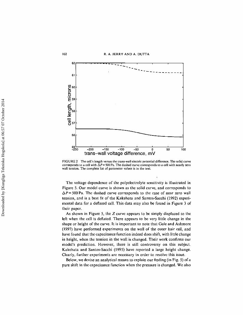
Figures 2-5 show the voltage dependence of the cell's length, radius, polyelectrolyte fraction, and polyelectrolyte sensitivity. In Figure 2, the solid curve corresponds to a cell with a trans-wall pressure difference of 500 Pa, and the dashed curve corresponds to a nearly deflated cell (one with nearly zero wall tension). The cell shortens in response to an increase in the trans- wall potential difference. Note that the length changes by over 1 % when the voltage is changed from one extreme value to the other. The process of deflating the cell can be represented as a vertical line extending from the solid curve to the dashed curve. Note that the cell elongates by approxi- mately 10% on deflation.
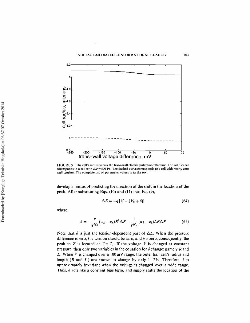
Figure 3 illustrates the response of the cell's radius to the trans-wall electric potential difference. The radius changes by over I% when the voltage is changed from one extreme to the other. The radius decreases in response to an increase in the trans-wall potential difference. On deflation, the radius decreases by about 22%.
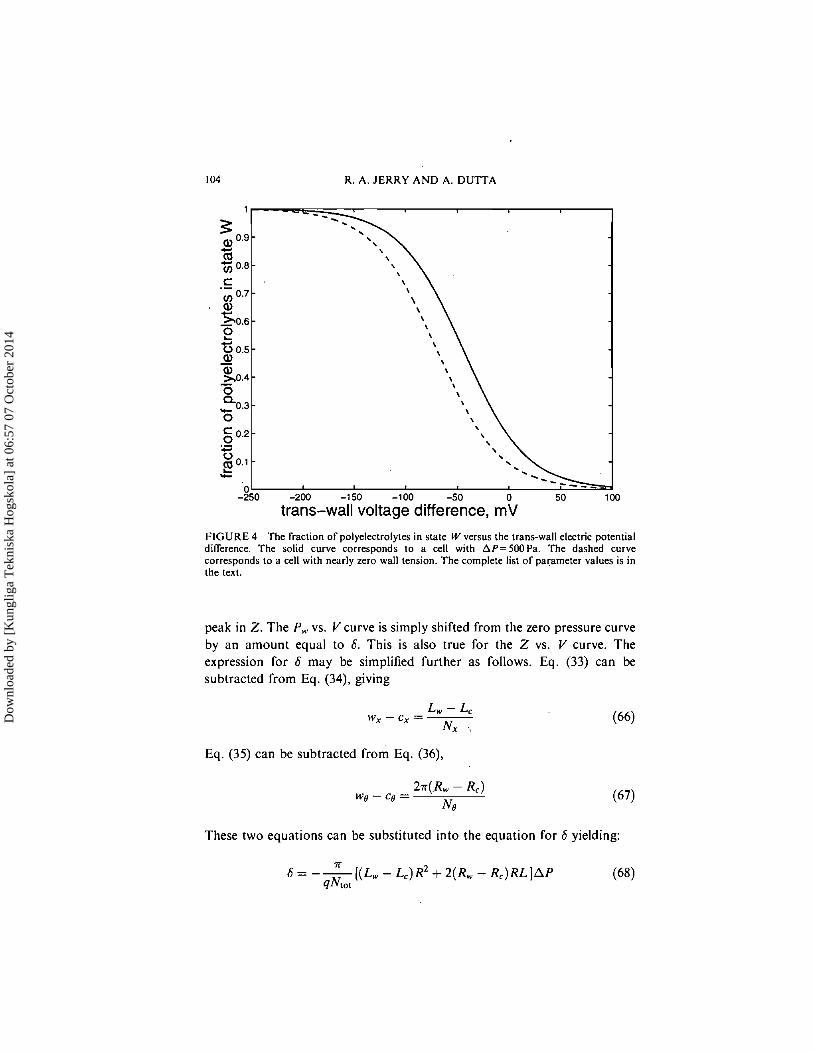
Figure 4 illustrates how P,, the fraction of polyelectrolytes in state W, changes as the trans-wall potential difference is changed. The dashed curve again corresponds to the case of a cell with nearly zero wall tension.
Dow
nloa
ded
by [
Kun
glig
a T
ekni
ska
Hog
skol
a] a
t 06:
57 0
7 O
ctob
er 2
014
R. A. JERRY AND A. DUTTA
FIGURE 2 The cell's length versus the trans-wall electric potential difference. The solid curve corresponds to a cell with AP= 500 Pa. The dashed curve corresponds to a cell with nearly zero wall tension. The complete list of parameter values is in the text.
62
61
60-
$ .- E 59
5 F 5 8 w - - - 8 5 7 -
56
55 -250
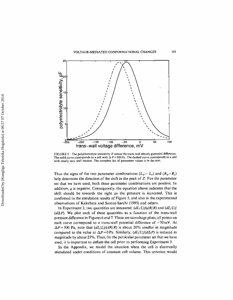
The voltage dependence of the polyelectrolyte sensitivity is illustrated in Figure 5. Our model curve is shown as the solid curve, and corresponds to AP=500Pa . The dashed curve corresponds to the case of near zero wall tension, and is a best fit of the Kakehata and Santos-Sacchi (1992) experi- mental data for a deflated cell. This data may also be found in Figure 3 of their paper.
As shown in Figure 5, the Z curve appears to be simply displaced to the left when the cell is deflated. There appears to be very little change in the shape or height of the curve. It is important to note that Gale and Ashmore (1997) have performed experiments on the wall of the outer hair cell, and have found that the capacitance function indeed does shift, with little change in height, when the tension in the wall is changed. Their work confirms our model's prediction. However, there is still controversy on this subject. Kakehata and Santos-Sacchi (1995) have reported a large height change. Clearly, further experiments are necessary in order to resolve this issue.
Below, we devise an analytical means to explain our finding (in Fig. 5) of a pure shift in the capacitance function when the pressure is changed. We also
trans-wall voltage difference, rnV
- * - - - - - ' - - - - ---_ ---- - - - - -
-
-
-
-200 -150 -100 -50 0 50 100
Dow
nloa
ded
by [
Kun
glig
a T
ekni
ska
Hog
skol
a] a
t 06:
57 0
7 O
ctob
er 2
014
VOLTAGE-MEDIATED CONFORMATIONAL CHANGES
-250 -200 -150 -100 -50 0 50
trans-wall voltage difference, rnV
FIGURE 3 The cell's radius versus the trans-wall electric potential difference. The solid curve corresponds to a cell with AP= 500 Pa. The dashed curve corresponds to a cell with nearly zero wall tension. The complete list of parameter values is in the text.
develop a means of predicting the direction of the shift in the location of the peak. After substituting Eqs. (10) and (1 1) into Eq. (9) ,
where
Note that 6 is just the tension-dependent part of AE. When the pressure difference is zero, the tension should be zero, and 6 is zero; consequently, the peak in Z is located at V = Vo. If the voltage V is changed at constant pressure, then only two variables in the equation for 6 change: namely R and L . When V is changed over a 100mV range, the outer hair cell's radius and length (R and L ) are known to change by only 1-2%. Therefore, 6 is approximately invariant when the voltage is changed over a wide range. Thus, 6 acts like a constant bias term, and simply shifts the location of the
Dow
nloa
ded
by [
Kun
glig
a T
ekni
ska
Hog
skol
a] a
t 06:
57 0
7 O
ctob
er 2
014
104 R. A. JERRY AND A. DUTTA
g 0.2 - \ \ .- \ .- \ 2 0.1 -
L .c
0. -250 -200 -150 -100 -50 0 50 100
trans-wall voltage difference, mV
FIGURE 4 The fraction of polyelectrolytes in stale W versus the trans-wall electric potential difference. The solid curve corresponds to a cell with AP=SOOPa. The dashed curve corresponds to a cell with nearly zero wall tension. The complete list of parameter values is in the text.
peak in 2. The P , vs. V curve is simply shifted from the zero pressure curve by an amount equal to 6. This is also true for the Z vs. V curve. The expression for 6 may be simplified further as follows. Eq. (33) can be subtracted from Eq. (34), giving
Eq. (35) can be subtracted from Eq. (36),
These two equations can be substituted into the equation for 6 yielding:
Dow
nloa
ded
by [
Kun
glig
a T
ekni
ska
Hog
skol
a] a
t 06:
57 0
7 O
ctob
er 2
014
VOLTAGE-MEDIATED CONFORMATIONAL CHANGES 105
FIGURE 5 The polyelectrolyte sensitivity Z versus the trans-wall electric potential difference. The solid curve corresponds to a cell with A P= 500Pa. The dashed curve corresponds to a cell with nearly zero wall tension. The complete list of parameter values is in the text.
Thus the signs of the two parameter combinations (L,- LC) and (R,,-R,) help determine the direction of the shift in the peak of 2. For the parameter set that we have used, both these parameter combinations are positive. In addition, q is negative. Consequently, the equation above indicates that the shift should be towards the right as the pressure is increased. This is confirmed in the simulation results of Figure 5, and also in the experimental observations of Kakehata and Santos-Sacchi (1995) and others.
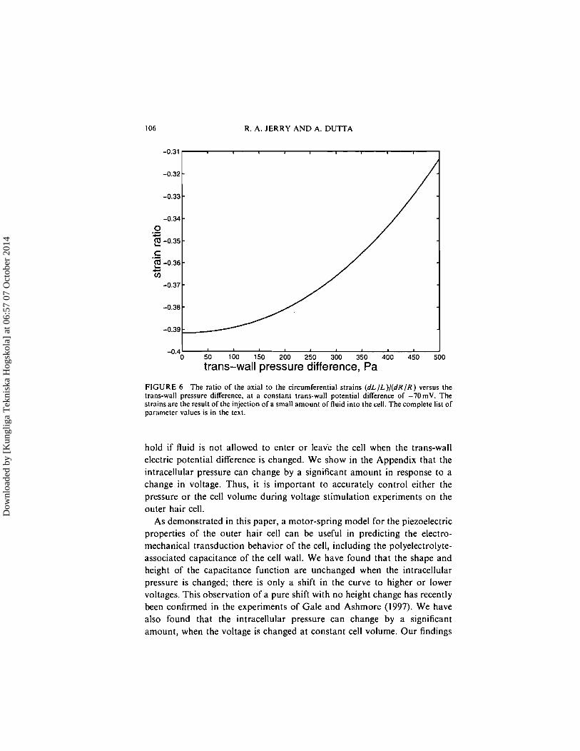
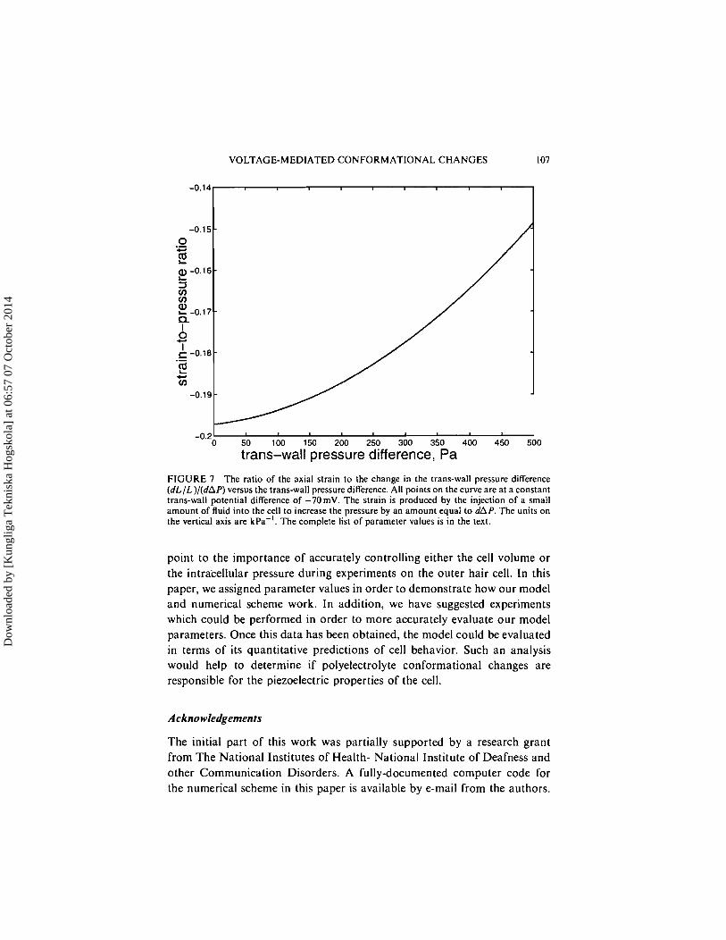
In Experiment 3, two quantities aremeasured: (dL/L)/(dR/R) and (dL/L)/ (dAP). We plot each of these quantities as a function of the trans-wall pressure difference in Figures 6 and 7. These are isovoltage plots; all points on each curve correspond to a trans-wall potential difference of -70mV. At A P = 500 Pa, note that (dL/L)/(dR/R) is about 20% smaller in magnitude compared to the value a t A P = 0 Pa. Similarly; (dL/L)/(dAP) is reduced in magnitude by about 25%. Thus, for the particular parameter set that we have used, it is important to deflate the cell prior to performing Experiment 3.
In the Appendix, we model the situation when the cell is electrically stimulated under conditions of constant cell volume. This criterion would
Dow
nloa
ded
by [
Kun
glig
a T
ekni
ska
Hog
skol
a] a
t 06:
57 0
7 O
ctob
er 2
014
106 R. A. JERRY AND A. DUTTA
-0.4 I 0 50 100 150 200 250 300 350 400 450 500
trans-wall pressure difference, Pa
FIGURE 6 The ratio of the axial to the circumferential strains ( d L / L ) / ( d R / R ) versus the trans-wall pressure difference, at a constant trans-wall potential difference of -7OmV. The strains are the result of the injection of a small amount of fluid into the cell. The complete list of paremeter values is in the text.
hold if fluid is not allowed to enter o r leave the cell when the trans-wall electric potential difference is changed. We show in the Appendix that the intracellular pressure can change by a significant amount in response to a change in voltage. Thus, it is important to accurately control either the pressure o r the cell volume during voltage stimulation experiments on the outer hair cell.
As demonstrated in this paper, a motor-spring model for the piezoelectric properties of the outer hair cell can be useful in predicting the electro- mechanical transduction behavior of the cell, including the polyelectrolyte- associated capacitance of the cell wall. We have found that the shape and height of the capacitance function are unchanged when the intracellular pressure is changed; there is only a shift in the curve to higher o r lower voltages. This observation of a pure shift with no height change has recently been confirmed in the experiments of Gale and Ashmore (1997). We have also found that the intracellular pressure can change by a significant amount, when the voltage is changed a t constant cell volume. Our findings
Dow
nloa
ded
by [
Kun
glig
a T
ekni
ska
Hog
skol
a] a
t 06:
57 0
7 O
ctob
er 2
014
VOLTAGE-MEDIATED CONFORMATIONAL CHANGES
-0.14
-0.2 1 I 0 50 100 150 200 250 300 350 400 450 500
trans-wall pressure difference, Pa
FIGURE 7 The ratio of the axial strain to the change in the trans-wall pressure difference (dL/L) / (dAP) versus the trans-wall pressure difference. All points on the curve are at a constant trans-wall potential difference of -70mV. The strain is produced by the injection of a small amount of fluid into the cell to increase the pressure by an amount equal to dAP. The units on the vertical axis are k ~ a - ' . The complete list of parameter values is in the text.
point to the importance of accurately controlling either the cell volume or the intracellular pressure during experiments on the outer hair cell. In this paper, we assigned parameter values in order to demonstrate how our model and numerical scheme work. In addition, we have suggested experiments which could be performed in order to more accurately evaluate our model parameters. Once this data has been obtained, the model could be evaluated in terms of its quantitative predictions of cell behavior. Such an analysis would help to determine if polyelectrolyte conformational changes are responsible for the piezoelectric properties of the cell.
Acknowledgements
The initial part of this work was partially supported by a research grant from The National Institutes of Health- National Institute of Deafness and other Communication Disorders. A fully-documented computer code for the numerical scheme in this paper is available by e-mail from the authors.
Dow
nloa
ded
by [
Kun
glig
a T
ekni
ska
Hog
skol
a] a
t 06:
57 0
7 O
ctob
er 2
014
108 R. A. JERRY AND A. DUTTA
The authors acknowledge useful discussions with Jonathon Gale. The use of the Biomedical Supercomputing Center at the Frederick National Cancer Institute (NCI-FCRDC) is greatly appreciated.
References
Abram, R. A. (1980i) "Theory of a Piezoelectric Plastic Film Transducer for Earphones", J. of Physics D : Appl. Phys., 13, 201 -207.
Abram, R. A. (1980ii) "Reaction Effects in Piezoelectric Plastic Film Transducers for Earphones", J. of Physics D: Appl. Phys., 13, 2237-2242.
Abram, R. A. (1980iii) "Coupled Oscillation Theory of a Noise Cancelling Microphone Using Piezoelectric Plastic Diaphragms", J. of Physics D : Appl. Phys., 13, 195-200.
Adelman, N. T., Stavsky, Y. and Segal, E. (1975) "Axisymmetric Vibrations of Radially Polarized Piezoelectric Ceramic Cylinders". J. of Sound and Vibrarion, 38, 245-254.
Ashmore, J. F. (1987) "A Fast Motile Response in Guinea-pig Outer Hair Cells: The Cellular Basis of the Cochlear Amplifier", J . Physiol. (Land.), 388, 323-347.
Chen, Q. X. and Payne, P. A. (1995) "Industrial Applications of Piezoelectric Polymer Transducers", Meas. Sci. Technol., 6 , 249-267.
Dallos. P. (1992) "The Active Cochlea", J. Neurosci., 12, 4575-4585. Dallos. P.. Hallworth, R. and Evans, B. N. (1993) "Theory of Electrically Driven Shape
Changes of Cochlear Outer Hair Cells", J. Neurophys., 70, 299-323. Dnvies, G., Murphy, P. V. and Maurer, G. (1984) "A Theoretical and Experimental Study o f a
Model Piezoelectric Membrane Headphone", J. Acousr. Soc. Am., 76, 661 -665. Gale. J . E. and Ashmore, J. F. (1997) "The Outer Hair Cell Motor in Membrane Patches",
Plugers Archiv-Eur. J. Physiol., 434, 267. Holley, M. C. and Ashmore, J . F. (1990) "Spectrin, Actin and the Structure of the Cortical
Lattice in Mammalian Cochlear Outer Hair Cells", J . Cell Sci., 96, 283-291. Hudspeth, A. J. (1989) "How the Ear's Works Work", Norure, 341, 397-404. Iwasa. K. H. (1994) "A Membrane Motor Model for the Fast Motility of the Outer Hair Cell",
J. Acousr. Soc. Am., 96, 2216-2224. Iwasa, K. H. and Chadwick, R. S. (1992) "Elasticity and Active Force Generation of Cochlear
Outer Hair Cells", J. Acousf. Soc. Am., 92, 3169-3173. Jerry, R. A. and Dutla, A. (1998i) "Molecular Motor and Electrokinetic Contributions to Outer
Hair Cell Electromotility", J. Neurophysiology, accepted, to appear January 1998 issue. Jerry, R. A. and Dutta, A. (1998ii) "Uniaxial Tensile Loading of the Outer Hair Cell: Explaining
the Charge Reversal Effect", in preparation. Jerry, R. A., Popel, A. S. and Brownell, W. E. (19951) "Outer Hair Cell Length Changes in an
External Electric Field. I. The Role of lntracellular Electro-osmotically Generated Pressure Gradients", J. Acousl. Sac. Am., 98, 2000-2010.
Jerry, R. A,, Popel, A. S. and Brownell, W. E. (1995ii) "Outer Hair Cell Length Changes in an External Electric Field. 11. The Role of Electrokinetic Forces on the Cell Surface", J. Acousl. Soc. Am., 98, 201 1-2017.
Jerry, R. A,. Popel. A. S. and Brownell, W. E. (1996) "Potential Distribution for a Spheroidal Cell Having a Conductive Membrane in an Electric Field", I E E E Trans. on Biomed. Engg., 43, 970-972.
Kakehata, S. and Santos-Sacchi, J . (1995) "Membrane Tension Directly Shifts Voltage Dependence of Outer Hair Cell Motility and Associated Gating Charge", Biophys. J.. 68, 2190-2197.
Kawai, H. (1969) "The Piezoelectricity in Poly(Viny1idene Fluoride)", Japanese Journal of Applied Physics, 8 , 975-976.
Loew, L. M. (1993) "Electrical Properties of Biomembranes", in Biomembranes: Physical Aspects, edited by M. Shinitzky (VCH, New York), 342-371.
Mitchell, J. A. and Reddy, J. N. (1995) "A Study of Embedded Piezoelectric Layers in Composite Cylinders", Trans. of the ASME, 62, 166- 173.
Dow
nloa
ded
by [
Kun
glig
a T
ekni
ska
Hog
skol
a] a
t 06:
57 0
7 O
ctob
er 2
014
VOLTAGE-MEDIATED CONFORMATIONAL CHANGES 109
APPENDIX: CHANGING THE VOLTAGE AT CONSTANT CELL VOLUME
The numerical scheme that was described earlier in this paper can be used to calculate R, L, and P, when the values of the input variables (V and AP) are known. In this section, we describe a numerical technique which can be used when the trans-wall potential difference is changed at constant cell volume. We use the term "constant volume" to mean that the volume of intracellular fluid remains unchanged during the experiment. Consequently, the intracellular pressure must change in response to the voltage change, in order for the cell's volume to remain constant. We will use the subscript i to refer to the initial state of the cell, before the voltage change is made..Thus, the initial conditions may be written: R , L , P,,, Vi and AP,. After the voltage has been changed, the conditions of the cell may be written as: Rfi L,-, P,> Vfand APj: To be consistent with our previous scheme, we will use dimensionless parameters as denoted by the asterisk superscript.
For this numerical scheme, it is assumed that R;, L; and Pzi have already been calculated with our previously-introduced numerical scheme (given values for the two inputs: V; and AP;). After the voltage is changed to VA the constant volume assumption means that the quantity (R*)'L* remains unchanged. Yet, the pressure difference must change from its initial value of AP; to a final value of APj . The numerical approach for this situation is actually easier than our previous scheme. This numerical scheme also involves iteration; values of R* must be selected. Then, the length L* can be evaluated immediately, because of the constraint: ( R * ) ~ L = (R;)'L.;, giving
Eq. (22) could then be solved for P,
This can be substituted into Eq. (23), which can be solved for AP*
AP* = Nx E- 1 D(l - H ) I
Dow
nloa
ded
by [
Kun
glig
a T
ekni
ska
Hog
skol
a] a
t 06:
57 0
7 O
ctob
er 2
014
110 R. A. JERRY AND A. DUTTA
This allows AP' to be evaluated using the previously-determined values of R* and L *. Then, P , can be evaluated from Eq. (65). These values can be substituted into Eq. (25), and a zero search can be performed until a solution is found. The solution yields the values of Rj, Lj, PL,. and A P j .
Overall, one can consider the input variables for a constant volume voltage change experiment as: V f , APf and V j . The output variables are: R f , Lf, Pi, R j , L j , Pwfi and A P j . The first three of the output variables are calculated using our numerical scheme from a previous section. Then, the last four output variables can be calculated using the numerical scheme that was presented in this section.
Consider a cell having the same values of the 13 parameters as those used in Figures 2-5. Suppose that A P is set to 500Pa, and V to -250mV. In this state, all the polyelectrolytes would be primarily in state W as shown in Figure 4. Now, suppose that V is changed to + IOOmV, at constant cell volume. Now, the polyelectrolytes would be primarily in state C. Our numerical technique may be used for this situation and gives AP, = 547 Pa. Thus, the intracellular pressure increased by almost 50Pa. For this particular parameter set, the pressure change is significant. This observation demonstrates that the intracellular pressure can change by a significant amount during a constant-volume voltage stimulation experiment.
Dow
nloa
ded
by [
Kun
glig
a T
ekni
ska
Hog
skol
a] a
t 06:
57 0
7 O
ctob
er 2
014