Embed Size (px)
Citation preview
Volcanic rifting at Martian grabens
Daniel Mege,1 Anthony C. Cook,2,3 Erwan Garel,4 Yves Lagabrielle,5
and Marie-Helene Cormier6
Received 28 January 2002; revised 17 January 2003; accepted 5 February 2003; published 22 May 2003.
[1] A large fraction of surface extension on Mars occurred at segmented grabens havingwidth/length ratios akin to oceanic rifts on Earth. Association with volcanic landformssuch as pit craters clearly suggests interconnection between tectonic and magmaticprocesses. A Martian rift evolution model is proposed on the basis of newgeomorphological and structural interpretations of imagery, high-resolution digitalelevation models (DEMs), scaled experimental modeling and three-dimensional boundaryelement modeling of magmatic and tectonic processes, and a comparison with terrestrialrifts. The DEMs were obtained from Mars Observer Laser Altimeter, Viking Orbiterstereo images, or a combination of both. Comparison of terrestrial rifts included Afar,Iceland, and the East Pacific Rise. The ambient extensional stress field induced byregional body forces is combined at depth with decompression melting and mantle plumethermal anomaly, resulting in emplacement of elongated magma reservoirs along thegrabens. Injection of dikes above the reservoirs and flood basalt eruption result in areservoir underpressurization of up to hundreds of MPa and induces surface collapse. Eachcollapse event is associated with an eruption of volcanic volumes akin to those ofindividual flow eruptions in large terrestrial igneous provinces. The geometry andmechanisms of graben formation and surface collapse are described and used to inferreservoir depth and width. We conclude from this study that giant dike swarms akin totypical giant terrestrial dike swarms are unlikely to underlie the volcanic Martian grabenson the basis one graben-one dike. Rather, every volcanic graben segment appears to own alocal dike swarm perhaps analogous to the dike swarms in the Icelandic fissurezones. INDEX TERMS: 5475 Planetology: Solid Surface Planets: Tectonics (8149); 5480 Planetology:
Solid Surface Planets: Volcanism (8450); 6225 Planetology: Solar System Objects: Mars; 8121
Tectonophysics: Dynamics, convection currents and mantle plumes; 8010 Structural Geology: Fractures and
faults; KEYWORDS: rifting, graben, pit crater, magma chamber, dyke
Citation: Mege, D., A. C. Cook, E. Garel, Y. Lagabrielle, and M.-H. Cormier, Volcanic rifting at Martian grabens, J. Geophys. Res.,
108(E5), 5044, doi:10.1029/2002JE001852, 2003.
1. Introduction
[2] Many Martian narrow grabens display collapse fea-tures. This paper provides a short review of mechanisms ofnarrow graben formation and discusses evidence that thecollapse features have a volcanic origin. We call narrowgrabens that have been altered by further collapse modified
grabens. Modified grabens include grabens associated withcatenae as well as other depression types. Relationshipsbetween graben formation and magmatic processes areexplored. The influence of dike emplacement (drivingpressure during dike propagation, pressure drop duringwithdrawal or freezing) in graben geometry and in theformation of pit craters and other depressions is discussed.Deeper processes such as magma chamber compaction andwithdrawal are then investigated. A qualitative model oftectonic extension simultaneous to magma emplacement atdepth is presented, and quantified using morphometricanalysis of collapse depressions, experimental modeling,and numerical modeling of magmatic deflation.
1.1. Martian Narrow Grabens
[3] Mars, Venus and the Moon all display so-called‘‘narrow grabens’’ [e.g., Golombek, 1979], typically 2–5km in width and hundreds or thousands of km in length(Figure 1). Earlier photoclinometric studies have shown thatin the Syria Planum-Valles Marineris area their depth iscommonly less than 100 m to a few hundred meters [Tanaka
JOURNAL OF GEOPHYSICAL RESEARCH, VOL. 108, NO. E5, 5044, doi:10.1029/2002JE001852, 2003
1Laboratoire de Tectonique, Universite Pierre et Marie Curie, Paris,France.
2Center for Earth and Planetary Studies, Smithsonian Institution,Washington, D. C., USA.
3Now at School of Computer Science and Information Technology,University of Nottingham, Nottingham, UK.
4Laboratoire de Geodynamique des Rifts et des Marges Passives,Universite du Maine, Le Mans, France.
5Institut de Recherche pour le Developpement, Universite de BretagneOccidentale, Plouzane, France.
6Lamont-Doherty Earth Observatory, Columbia University, Palisades,New York, USA.
Copyright 2003 by the American Geophysical Union.0148-0227/03/2002JE001852$09.00
10 - 1
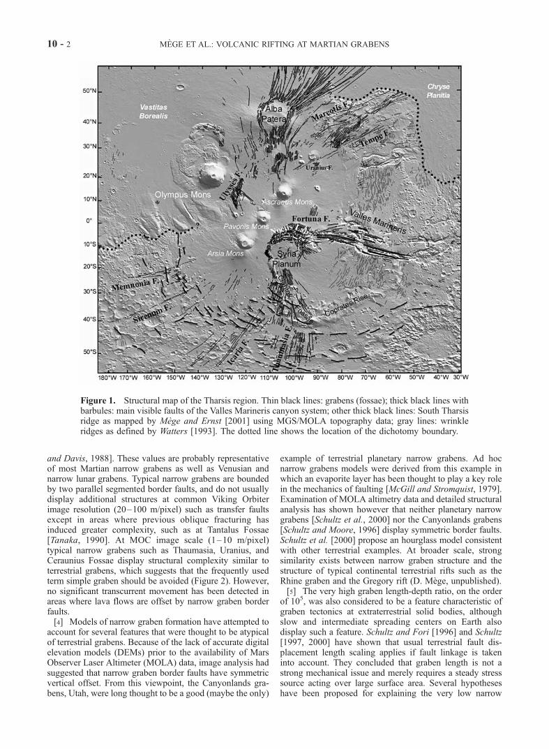
and Davis, 1988]. These values are probably representativeof most Martian narrow grabens as well as Venusian andnarrow lunar grabens. Typical narrow grabens are boundedby two parallel segmented border faults, and do not usuallydisplay additional structures at common Viking Orbiterimage resolution (20–100 m/pixel) such as transfer faultsexcept in areas where previous oblique fracturing hasinduced greater complexity, such as at Tantalus Fossae[Tanaka, 1990]. At MOC image scale (1–10 m/pixel)typical narrow grabens such as Thaumasia, Uranius, andCeraunius Fossae display structural complexity similar toterrestrial grabens, which suggests that the frequently usedterm simple graben should be avoided (Figure 2). However,no significant transcurrent movement has been detected inareas where lava flows are offset by narrow graben borderfaults.[4] Models of narrow graben formation have attempted to
account for several features that were thought to be atypicalof terrestrial grabens. Because of the lack of accurate digitalelevation models (DEMs) prior to the availability of MarsObserver Laser Altimeter (MOLA) data, image analysis hadsuggested that narrow graben border faults have symmetricvertical offset. From this viewpoint, the Canyonlands gra-bens, Utah, were long thought to be a good (maybe the only)
example of terrestrial planetary narrow grabens. Ad hocnarrow grabens models were derived from this example inwhich an evaporite layer has been thought to play a key rolein the mechanics of faulting [McGill and Stromquist, 1979].Examination of MOLA altimetry data and detailed structuralanalysis has shown however that neither planetary narrowgrabens [Schultz et al., 2000] nor the Canyonlands grabens[Schultz and Moore, 1996] display symmetric border faults.Schultz et al. [2000] propose an hourglass model consistentwith other terrestrial examples. At broader scale, strongsimilarity exists between narrow graben structure and thestructure of typical continental terrestrial rifts such as theRhine graben and the Gregory rift (D. Mege, unpublished).[5] The very high graben length-depth ratio, on the order
of 105, was also considered to be a feature characteristic ofgraben tectonics at extraterrestrial solid bodies, althoughslow and intermediate spreading centers on Earth alsodisplay such a feature. Schultz and Fori [1996] and Schultz[1997, 2000] have shown that usual terrestrial fault dis-placement length scaling applies if fault linkage is takeninto account. They concluded that graben length is not astrong mechanical issue and merely requires a steady stresssource acting over large surface area. Several hypotheseshave been proposed for explaining the very low narrow
Figure 1. Structural map of the Tharsis region. Thin black lines: grabens (fossae); thick black lines withbarbules: main visible faults of the Valles Marineris canyon system; other thick black lines: South Tharsisridge as mapped by Mege and Ernst [2001] using MGS/MOLA topography data; gray lines: wrinkleridges as defined by Watters [1993]. The dotted line shows the location of the dichotomy boundary.
10 - 2 MEGE ET AL.: VOLCANIC RIFTING AT MARTIAN GRABENS

graben width-length ratio, on the order of 10�3–10�2.Tanaka and Golombek [1989] proposed that narrownessresults from existence of deep tension fractures whose uppertermination would correspond to a rheological interfacesuch as a permafrost layer or the base of a megaregolith,where V-shaped grabens would have initiated and propa-gated toward the surface. Model assessment is made diffi-cult by apparent lack of terrestrial analogs. However,mechanically the maximum depth a tension fracture canreach before it turns into a fault on Mars, even under highfluid pressure conditions, cannot exceed 1 or 2 km [e.g.,Mege and Masson, 1997]. This corresponds to a fracture
length that can hardly exceed several kilometers, and istherefore too small to explain planetary narrow grabenlength. Melosh and Williams [1989] advocated that slipalong a single fault in elastic medium may generate acompression zone at depth that locks the fault and inducesnucleation of an antithetic fault at a short distance from thefirst fault. This model requires that the crust be intact beforethe graben forms, and that the extension rate be low enoughnot to annihilate the compression at the bottom of the firstfault after slip. This is necessary in order to make thenucleation of another fault necessary instead of continuingslip along the first fault. The most recent hypothesis has
Figure 2. High-resolution views of narrow grabens. (a) Typical narrow graben at Alba Fossae,northwest of Alba Patera. Note that the northern rim of the impact crater at the northern border fault scarpwas cut by the border fault and subsequently buried, which is evidence of postfaulting mass wasting atthe border fault. In this example, postfaulting mass wasting may explain the absence of along-strikevariation of fault displacement. MOC image M09-06510 centered at 112.35�W, 45.49�N, 6.21 m/pixel.(b) Typical narrow graben at Thaumasia Fossae. Low shield volcanoes are aligned along the westerngraben border fault. Although major collapse features are not observed within the graben, local collapseoccurred at summit calderas (<50 m diameter), suggesting volcanic activity contemporaneous withtectonic extension. MOC image M00-00991 centered at 95.31�W, 43.96�N, 2.76 m/pixel. MOC imagesby NASA/JPL/MSSS. The coordinates given in the figure captions refer to the MGS/MOLA datum forMOC images and Viking datum for Viking images.
MEGE ET AL.: VOLCANIC RIFTING AT MARTIAN GRABENS 10 - 3

been that the small width-length ratio results from strainconcentration at the surface above nonfeeder dikes either inresponse to magma pressure or density and strength contrastwith the host rock [Schultz, 1988; Tanaka et al., 1991; Megeand Masson, 1996]. A reason why large strain was achievedby the formation of many narrow graben swarms instead ofby the growth of a few major grabens, may also be that thenarrow grabens formed above corresponding giant dikes,similar to the dikes in terrestrial giant mafic swarms. Earlier,Wise [1976] had suggested that strain distribution might be aconsequence of the existence of a shallow ductile layerbelow the grabens.[6] The steady broad-scale stress sources required for
narrow graben development are likely to have originatedfrom the magmatic activity and lithosphere loading by theTharsis and Elysium volcanic provinces. Merle and Borgia[1996] showed that uplift of volcanic topography generatesbody forces inducing gravitational spreading of the to-pography, resulting in the development of radiating grabensfrom the central region to the lower uplift flank. They alsoshowed that graben width and spacing depends on thebrittle/ductile crust ratio. Furthermore, Van Wyk de Vriesand Merle [1996] showed that topographic building in anextensional remote stress field results in long and narrowgrabens extending from the summit of the uplift to the mostremote areas in which the same remote stress field exerts,which is pretty much the case for many narrow grabensaround the Tharsis and Elysium volcanic shields. Stressmodeling of the whole Tharsis magmatic load (includingboth the topographic load and the accreted magmaticmaterials) was shown to reproduce part of the radiatingextensional patterns in some detail [Banerdt and Golombek,2000]. Other possible contributing regional stress sourcesinclude plume-induced uplift [Mege, 2001] and overpres-sure in huge central magma chambers in the Tharsis andElysium regions [Mege and Masson, 1996].
1.2. Modified Grabens, Pits, and Troughs
[7] Narrow grabens are frequently associated withaligned collapse depressions, and occasionally with positiverelief of volcanic origin including lava flows, cinder cones,spatter cones, small shield volcanoes, and spatter ridges[Cattermole, 1986, 1992; Davis et al., 1995; Mege andMasson, 1996]. Frequently the depressions have partly orwholly removed the narrow graben border faults, and areassociated with newly formed fractures.[8] Modified grabens are mostly distributed at and around
the large Tharsis and Elysium volcanic shields, and in mostregions on Mars that were deformed in extension. Figure 3shows typical relationships observed between narrow gra-bens and modified grabens at Tempe Terra, Elysium Fossae,and southeast of Valles Marineris. At a first approximation,the depressions include:[9] (1) pits and pit chains (Figure 4a) and elongated U-
shaped troughs of similar depth aligned with the pits (Figure4b). Alignments of pits and elongated U-shaped troughsmake catenae, a planetary term first used by Antoniadi[1930] to name albedo features and redefined from 1973to mean crater chains, many of which are associated with agraben.[10] (2) shallow flat-floored depressions (Figure 4c),
usually in areas where pits are also observed. Some shallow
flat-floored depressions are ovoid (many examples arefound at Tempe Terra) while the others have a markedlinear trend (e.g., Elysium Chasma area).[11] (3) linear U-shaped troughs (Figure 4d). The differ-
ence made here with elongated U-shaped troughs is basedon length. Linear U-shaped troughs are wider than grabensin the same area and have monotonous U-shaped wallmorphology displaying no evidence of faulting for lengthsfrequently greater than 100 km.[12] (4) small chasmata, such as part of the Elysium
Fossae (Figure 4e) and the chasmata aligned with pit chainsparallel to the main Valles Marineris grabens. Small chas-mata are wider and deeper than U-shaped troughs (e.g.,Elysium Chasma depth is some 2 km deep [MOLA ScienceTeam, 1997]).[13] Collapse features are either observed within narrow
grabens, laterally connected to narrow grabens, or alignedparallel to narrow grabens but with no apparent connectionat surface. In the latter case, either graben fault scarpcollapse occurred along the whole graben, or a narrowgraben never formed, meaning that narrow graben forma-tion and U-shaped trough formation may result from thesame process but without any causal link.1.2.1. Pits and Pit Chains[14] Pits and coalescing pits have been interpreted as pit
craters formed by pressure drop above dikes [Cattermole,1992; Davis et al., 1995; Mege and Masson, 1996; Liu andWilson, 1998; Scott et al., 2000], and in a few locations asmaars [McGetchin and Ullrich, 1973; Mege and Masson,1996], suggesting that in some instances graben formationshould have been associated with dike emplacement [Megeand Masson, 1996; Wilson and Head, 2000; Ernst et al.,2001]. Some pits have a well-preserved conical shape anddisplay evidence of mass wasting on the floor, whereassome others have flat floor and were filled in almost entirelyby smooth materials, probably lava flows fed by ring dikesduring pit collapse [e.g., Best and Christiansen, 2001, p.220]. Well-known terrestrial analogs include pit craters atKilauea [Carr and Greeley, 1980] thought to have formedby stoping over a propagating dike [Okubo and Martel,1998].[15] Although pits and troughs are frequently observed to
lie along the grabens and parallel to the border faults, insome areas pit crater chains are not associated with exten-sional faulting, or follow en echelon patterns oblique tograbens with an angle on the order of 15�. In areas whereevidence of crosscutting relationships are found, pit cratersand other depressions are always observed to cut grabenborder faults, which shows that they were systematicallyformed later. No argument has been found as to the timespan between grabens and pit crater formation.1.2.2. Elongated U-shaped Troughs, ShallowFlat-Floored Depressions, and Small Chasmata[16] In many areas such as Valles Marineris it can be
observed that a full range of transitional morphologies existbetween coalescing pit chains and elongated U-shapedtroughs (Figure 3c). Elongated U-shaped troughs are mor-phologically analog to the selenic slot-shaped vents [Greeleyand Schultz, 1977]. Formation by collapse between individ-ual pit craters is supported by well documented terrestrialanalogs, especially at the Snake River Plain (King’s Bowl)[Greeley et al., 1977]; Wild Horse Corral vent [Greeley,
10 - 4 MEGE ET AL.: VOLCANIC RIFTING AT MARTIAN GRABENS

Figure 3. Depressions associated or aligned with narrow grabens at (a) Mareotis Fossae, (b) ElysiumChasma, and (c) Coprates Catena (southeast of Valles Marineris). NASA/JPL Viking Orbiter 1 images255S11-13 (79 m/pixel), 541A37 (143 m/pixel), and 610A07 (200 m/pixel).
MEGE ET AL.: VOLCANIC RIFTING AT MARTIAN GRABENS 10 - 5

1977a]; Hell’s Half Acre vent [Karlo, 1977]; SnowdriftCrater and volcanic depressions of the Inferno Chasm [Gree-ley, 1977b] in Hawaii (Mauna Ulu summit vent, whosemechanisms of formation could be observed during the1969–1974 eruption [Carr and Greeley, 1980]), and at theErta Ale in Afar [e.g., Tazieff, 1973]. Shallow flat-flooreddepressions are interpreted as lava ponds in volcanic vents byanalogy with terrestrial observations [e.g., Greeley, 1977b].[17] Chasmata are of two kinds. The largest chasmata
observed at Valles Marineris are mainly tectonic structuresthat were subsequently enlarged by mass wasting processes[e.g., Peulvast et al., 2001], but the case has been made ofearlier pretectonic trough initiation [Schultz, 1998]. Smallchasmata discussed in this paper, such as on Figures 3b and3c, display little observational evidence of faulting. Wethink that alignment with morphologic types of volcanicorigin argues in favor of volcanic collapse origin. Thedifference between U-shaped troughs and chasmata mayprimarily be a matter of size and depth of the collapsed roofof the underlying magma body.[18] In some regions the formation of the linear troughs,
and the chasmata, has been ascribed to surface materialcollapse into deep tension cracks opening at a crustal level
coinciding with the depth at which border faults connect[Tanaka and Golombek, 1989]. Following several previousworks [Schultz, 1988; Mege and Masson, 1996; Wilson andHead, 2000; Scott et al., 2000; Mege, 2001], we favor thevolcanic hypothesis because of the apparent lack of terres-trial analogs of large linear collapse structures along tensioncracks, the many terrestrial analogs described, and themarkedly volcanic modified narrow graben setting. Thisinterpretation is consistent with evidence from MOLAaltimetry data that assuming constant crustal density, thealignments of narrow chasmata and catenae around themajor Valles Marineris chasmata are associated with abnor-mally thick crust [Zuber, 2001]. Accounting for crustaldensity variations associated with linear magmatic intru-sions below the pit crater chains would tend to remove theexcess crustal thickness and provide a satisfactory alterna-tive interpretation of the gravity field.1.2.3. Linear U-shaped Troughs[19] In some places, such as Memnonia Fossae, linear U-
shaped troughs have been interpreted as collapse featuresresulting from dike tips approaching groundwater or groundice level [Mege and Masson, 1996; Montesi, 2001]. Fre-quent association with pit craters and elongated U-shaped
Figure 3. (continued)
10 - 6 MEGE ET AL.: VOLCANIC RIFTING AT MARTIAN GRABENS
troughs suggests that the depressions formed by collapseabove magma bodies [Mege and Masson, 1996;Mege et al.,2000]. High-resolution (MOC) images commonly show thatlinear U-shaped troughs widen through landsliding and theretreat of unstable normal fault scarps (e.g., Figure 5).Linear U-shaped troughs are common in southwesternTharsis (Memnonia, Sirenum and Icaria Fossae) and Nand NE of Alba Patera. (Tantalus Fossae).1.2.4. Graben Formation and Collapse Mechanisms[20] On Earth, oceanic rifts at slow spreading ridges (and
in places on fast spreading ridges [Lagabrielle and Cormier,1999]) are examples of elongated and segmented narrowgrabens thousands of km long in a volcanic setting, asso-ciated with a broad-scale stress field. They may be goodstructural analogs of planetary narrow grabens, even thoughoceanic expansion has not occurred there. This paperinvestigates the interaction between tectonic extension andmagmatic processes with the view to proposing a compre-hensive model of narrow graben, and modified grabenformation, by a mechanism akin to volcanic rifting on Earth.[21] In terrestrial volcanic rift tectonics, dikes are major
connectors between deep and surface processes [e.g., For-slund and Gudmundsson, 1991]. It has been observed thatsome giant mafic dike swarms in terrestrial hotspot setting[Ernst et al., 1996] are of similar length to Martian grabens[Mege and Masson, 1996; Ernst et al., 2001]. On thesegrounds, geologic mapping of the relationships between
grabens and volcanic landforms on Mars has led to theinterpretation that the modified grabens may have formedabove giant mafic dikes [Mege and Masson, 1996; Wilsonand Head, 2000; Scott et al., 2000] akin to the dikes in thegiant terrestrial swarms. Similar interpretations have beenmade on the Moon [Head and Wilson, 1994] and Venus[McKenzie et al., 1992; Grosfils and Head, 1994a, 1994b;Koenig and Pollard, 1998]. This popular tectonic conceptinvolves a common mechanism whereby graben open atsurface simultaneously to dike emplacement at depth onmost silicate planets. This would occur in response to thedriving pressure (ambient stress minus magma pressure)during dike emplacement. The giant swarms inferred onMars would be either radial or concentric around majorvolcanic centers, which has justified comparison with thoseterrestrial giant dike swarms that radiate from hotspotcenters [Ernst et al., 1995]. The dikes from giant maficswarms are classically considered to have flown upwardabove the melting source and laterally toward outer regions[Ernst and Baragar, 1992], although the case for verticallyfed radiating swarm has been made [Kumarapeli et al.,1990]. If an analogy with Martian dikes exists the dikesshould probably be mafic as well in order not to cool toorapidly before freezing.[22] However, there are several unanswered problems
with the dike interpretation, such as structural relationshipsbetween individual dikes and grabens of the size observed.
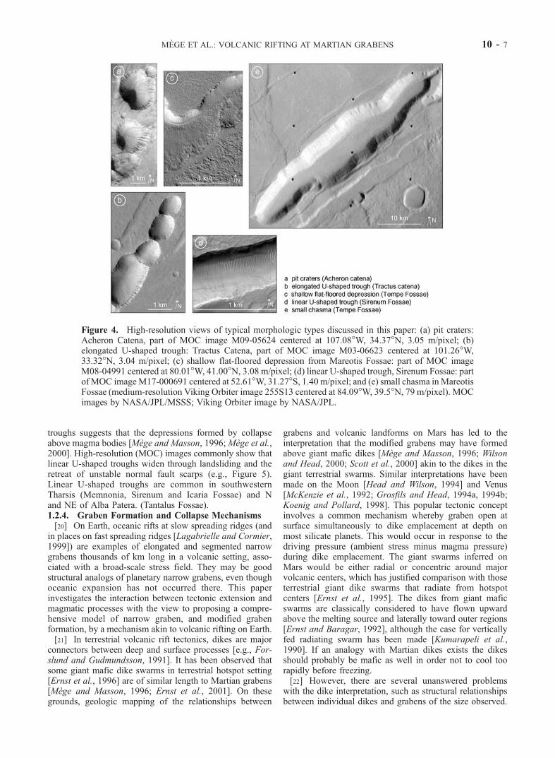
Figure 4. High-resolution views of typical morphologic types discussed in this paper: (a) pit craters:Acheron Catena, part of MOC image M09-05624 centered at 107.08�W, 34.37�N, 3.05 m/pixel; (b)elongated U-shaped trough: Tractus Catena, part of MOC image M03-06623 centered at 101.26�W,33.32�N, 3.04 m/pixel; (c) shallow flat-floored depression from Mareotis Fossae: part of MOC imageM08-04991 centered at 80.01�W, 41.00�N, 3.08 m/pixel; (d) linear U-shaped trough, Sirenum Fossae: partof MOC imageM17-000691 centered at 52.61�W, 31.27�S, 1.40 m/pixel; and (e) small chasma inMareotisFossae (medium-resolution Viking Orbiter image 255S13 centered at 84.09�W, 39.5�N, 79 m/pixel). MOCimages by NASA/JPL/MSSS; Viking Orbiter image by NASA/JPL.
MEGE ET AL.: VOLCANIC RIFTING AT MARTIAN GRABENS 10 - 7

On the one hand, models ascribing graben opening todriving pressure are grounded on extrapolation of simplenumerical and laboratory experiments there were designedfor other purposes and may not apply at the depth giantdikes are thought to propagate at high lithostatic pressure.Moreover, driving pressure cannot explain volcanic col-lapse, which is the key argument for the interpretation ofexisting magma body underlying grabens since faultingdoes not inform on stress source. On the other hand, modelsof pit and trough formation by magmatic processes have notinvestigated relationships with grabens nor discussed theempty volume that can reasonably be made available by
magmatic collapse at the top of single dikes. Therefore, inthe first step this paper thoroughly examines the argumentson which the dike emplacement interpretation has beenbased in order to show that in most cases dike emplacementis simply not enough to explain graben formation. Instead oftectonic stretching associated with emplacement of singledikes, this paper proposes that individual grabens displayingvolcanic morphology may be akin to individual rift zonessuch as those observed at plate boundaries on Earth. Thedikes in the rift zones are underlain by magma reservoirselongated along graben trend. The likely absence of platerecycling on Mars (Sleep [1994a] presented an alternative
Figure 5. High-resolution image of two troughs being broadened, forming a U-shape profile fromnormal fault scarp destabilization and landsliding. The trough in Figure 5a fed a lava pond east of the areadisplayed on this image. Ceraunius Fossae, part of MOC image M09-05279 centered at 110.53�W,28.33�N, 4.53 m/pixel. MOC image by NASA/JPL/MSSS.
10 - 8 MEGE ET AL.: VOLCANIC RIFTING AT MARTIAN GRABENS

view) has precluded oceanic expansion from operating atmodified grabens so that modified graben evolution may becompared with a short tectonic and magmatic rifting periodat oceanic rifts.[23] In a second step the relationships between magmatic
processes at depth and surface processes are investigated.The collapse depressions associated with the volcanicprocesses that accompany rifting are measured by volumeextraction from DEMs. The depth and thickness of thedeflating body are determined from the geometry of grabensand troughs using experimental models. Where mass wast-ing has removed the initial geometry of grabens and pits, theexperimental models are no longer of use, and the depth andsize of the deflating magma body are investigated usingthree-dimensional boundary element modeling for variablemagma pressures.
2. Surface Stretching and Dike Driving Pressure
2.1. Theory
[24] Terrestrial graben formation, in relation to magmaticactivity, has been investigated on active volcano flanks or ina rifting setting. In these regions shallow dike emplacementwas seismically correlated with the opening of grabencentimeters to tens of centimeters high. Linear ElasticFracture Mechanics (LEFM) predicts that two extensionalstress peaks will be observed at the surface on both sides ofa dike propagating at depth [Pollard and Holzhausen, 1979;Pollard et al., 1983]. If the driving pressure overcomes thetensile strength of the host rock, then surface failure willoccur as tension cracks [Schultz, 1996], a pattern that is alsoobserved in experimental models of dike emplacement[Mastin and Pollard, 1988]. Experimental models of suc-cessive magma injections, within the same dike fracture,predict that the tension cracks at surface will gain a verticaloffset, and gradually join deeper fractures until a grabenforms [Mastin and Pollard, 1988]. These models provide(with some uncertainty) quantitative relations allowing oneto infer dike depth from graben border fault spacing, andalso dike width and from horizontal strain. The models havebeen used to infer subsurface dike geometry on Venus[Grosfils and Head, 1994b], the Moon [Head and Wilson,1994], Mars [Mege and Masson, 1996], and at an EastPacific rise segment [Chadwick and Embley, 1998].[25] However, several lines of evidence suggest that
driving pressure may have only marginally contributed toplanetary narrow graben formation and evolution. First,there is no need for driving pressure to form the narrowgrabens. Existence of many unmodified narrow planetarygrabens parallel to modified grabens (and of likely similarage) suggests that the magnitude of the ambient stress fieldshould have been strong enough to produce narrow grabensalone. Moreover, stretching at the giant Valles Marinerisgraben system during a large part of the Tharsis history, (inclose proximity to narrow grabens and parallel to them)clearly shows that the ambient stress was high enough toproduce significant extensional strain without the help ofdike driving pressure. Furthermore, observation that col-lapse features usually cut narrow graben structures and areassociated with additional faulting suggests that if dikeoverpressurization is involved in graben formation, a sub-sequent mechanism of both extensional faulting and surface
collapse is anyway required. As normal faulting is usuallyinvolved in volcanic collapse [Roche et al., 2000], faultinginduced by driving pressure is unnecessary. This issue isfurther discussed and complemented hereafter.
2.2. Critical Assessment of Terrestrial Examples
[26] Graben formation associated with the propagation ofmeter-scale width dikes has been reported in Hawaii, Ice-land, the Asal-Ghoubbet rift, and Etna. The observed sur-face strain at these sites was compared with results fromLEFM and experimental models [Pollard et al., 1983;Mastin and Pollard, 1988; Rubin, 1992; Bonafede andOlivieri, 1995]. Theoretical displacement patterns could ingeneral match the observed geodetic displacement patterns,though the predicted displacement magnitude was notaccurately reproduced in every case. Our interpretation ofgraben formation above the emplacing dike at the Kraflafissure swarm of Iceland, and Asal-Ghoubbet rift zone inAfar [Pollard et al., 1983; Rubin, 1992], is that dikeemplacement could instantaneously increase the deviatorictensor, that was already near to failure, and consequentlyrelease stress gradually built at the plate boundary above theemplacing dike. This stress would have been released lateranyway, although possibly elsewhere.[27] At the Kilauea southeastern rift zone [Pollard et al.,
1983], where long term volcano flank landsliding isobserved, magma pressure may have also added the smallstress increment that triggered slope failure, whereas mostof the deviatoric stress is from gravitational origin. Recur-rent dike dilation pulls the volcano flank laterally, andnormal faulting at surface may only result from the lateralfree boundary, which results in flank gravity destabilization,as discussed by Elsworth and Voight [1996] and Morgan etal. [2000]. Moreover, between 1976 and 1982 abundantseismicity occurred despite dike emplacement quiescence[see, e.g., Cayol et al., 2000] and suggests that dikeintrusion may only be one of several mechanisms by whichvolcano flank seaward spreading occurs. Additional evi-dence that magma pressure has played a minor role is that ifthe magma pressure in shallow dikes was to play a key rolein graben formation, then the southwestern rift zone shouldbe much wider than it is actually observed [Garcia andDavis, 2001]. In these three cases, (Iceland, Afar, andHawaii) the source of ambient stress is long lasting. Thissuggests that a large part of the stress released throughgraben formation would have been released anyway butlater if dike emplacement did not occur. It also suggests thatthe key role of dike emplacement may not be grabenformation, rather, at most, initial strain focus above the dike.[28] Several lines of evidence support this view. (1) In
LEFM models, the total vertical displacement modeled atsurface above the dike is significantly smaller than theobserved displacement [Pollard et al., 1983, Figures 13and 14], suggesting that additional remote stress played arole in the total strain measured. (2) A far better agreementbetween measured and modeled displacement is obtained ifthe graben border faults were already formed when the dikepropagates. In that case the propagating dike will onlyinduce fault slip ahead of the dike [Rubin, 1992]. Thisshows that dike emplacement can induce graben formationif a remote stress has already begun the work. (3) Exper-imental models predicting dike-induced grabens [Mastin
MEGE ET AL.: VOLCANIC RIFTING AT MARTIAN GRABENS 10 - 9
and Pollard, 1988] were not scaled according to mechanicalscaling laws [Hubbert, 1937]; instead, the physical param-eters of the crust were adjusted until grabens similar to thoseobserved in nature could be reproduced. Mastin and Pollard[1988] have clearly warned against misinterpretations byemphasizing that their results only provide ‘‘a possiblemodel for deformation that can be studied by direct obser-vation’’. (4) In the Etna example, a gravity anomaly studyhas shown that a graben formed above a dike months afterthe dike was emplaced [Bonafede and Olivieri, 1995]. Inaddition, the magnitude of the observed anomaly is signifi-cantly larger than that be predicted by simple dike intrusion,suggesting that the relationships between dike emplacementand graben formation may be more complex than expectedfrom simple models of pressurized dike emplacement.
2.3. Assessment of LEFM From Field Observations atLarge Igneous Provinces
[29] Perhaps the best terrestrial analogs of the Tharsis andElysium volcanic provinces on Mars [Mege and Masson,1996; Mege, 2001] are dikes in large igneous provinces thatare usually nonfeeders. This has been explained by dikepropagation in the neutral buoyancy zone (NBZ) in the crust[Turcotte, 1990; Lister and Kerr, 1991], which on terrestrialcontinents has been estimated to ca. 3 km depth [Lister andKerr, 1991; Wilson and Head, 1994]. A strong argumentagainst major influence of driving pressure on grabenformation is that high confining pressure at typical NBZdepth on Earth probably renders LEFM modeling inappli-cable [Rubin, 1993]. More appropriate is cohesive zone dikemodeling, an approach that is not designed to predict hostrock behavior around dike tip but makes surface fracturinghighly unlikely [Rubin, 1993].[30] Field evidence at mafic dike upper tip usually con-
firms that cohesive zone modeling is more appropriate thanLEFM. LEFM predictions may be tested two ways in thefield. First, in elastic models stress concentrate at dike tip,where theoretically stress becomes infinite [e.g., Pollard etal., 1983], so that although LEFM does not allow that dikestops propagating. If for some (unpredicted) reason thisoccurs, one would expect the dike tip profile at a givensegment to be linear or penny-shaped, a feature that can bereadily tested in the field. Second, a graben should formabove the dike, which is also easily tested in the field in areaswhere erosion allows. Surface strain should scale withmagma overpressure, which also partly governs the widthof the dike during the intruding event, in conjunction withother factors [Rubin, 1993].[31] Observations at large igneous provinces do not con-
firm either of these predictions. Analysis of magma flow inmeter-wide mafic dikes as well as field observation ofinternal chilled margins in thicker dikes suggest that if wallmeltback does not occur (in which case dike growth does notaffect the stress regime [see Bruce and Huppert, 1990;Fialko and Rubin, 1999]), most mafic dikes thicker thanca. 1 m were formed by more than 1 magma injection[Gudmundsson, 1984; Baer, 1995; Platten, 2000]. In Ice-land, the dike width near upper tip is commonly 0.5–2 m,which probably reflects dike dilation during the last injectionevent [Gudmundsson, 1995a]. Therefore emplacement ofthick dikes, such as those required for explaining narrowgraben formation by driving pressure, are achieved through
many magma pulses. This has major implications in terms ofstrain distribution. In order for a magma pulse to inject intoan earlier dike fracture, the magma previously intrudedshould not be fully solidified. Magma emplacement duringa given magma pulse is frequently associated with tensilefracturing parallel to the dike plane on both sides of the dikeupper tip [e.g., Delaney et al., 1986]. These fractures arefilled in by subsequent injected magma, which allows thenew sheet to attain a shallower level in the crust and createnew small-scale fractures above the new tip [Gudmundsson,1995a]. Every new magma injection fills in the fracturesformed by the previous injection above the propagating diketip. This results in the common observation that even thethickest vertical dikes gradually narrow upward toward theupper tip zone, where they suddenly display a one to tens ofmeter-scale sawtooth/sickle geometry in vertical cross sec-tion (e.g., Gudmundsson [1984, 1995a] and personal obser-vation by the authors in various regions). As a result, countryrock fracturing resulting from the whole dike injectionhistory does not take the form of broad-scale tectonicstructures. After the last injection, fracturing at dike tip isnever larger than what would have been expected from asingle intrusion event. Therefore, even though 10 to 100meter wide dikes (resulting from multiple injections) attain acrustal depth that is shallower than the depth of a single dikeinjection, surface fracturing above the dike is negligible.Moreover, field observations at mafic dikes, including dikestens of meters thick, frequently shows that the uppermostdike tip segment is tapered, or snakes within the host rockover distances of centimeters to a few meters. Frequently thedike tip follows existing rock discontinuities [Gudmundsson,1984; Delaney et al., 1986], or grain boundaries [Hoek,1994, 1995]. These observations suggest low pressure at thedike tip, and favor cohesive zone models of dike tip ratherthan LEFM. Finally examination by the authors of terrainslocated above dike tips, in various igneous environments, forexample, the Ethiopian igneous province, never revealedexamples of grabens located directly above the tip. This isconfirmed by observations reported in the literature [e.g.,Gudmundsson, 1984]. Possible examples of grabens locatedabove dike tips would be interpreted as evidence that bothmay have formed in a similar or the same stress field, forinstance a regional mantle plume-related extensional stressfield. It would not provide any evidence as to the role ofmagma pressure in graben formation.
2.4. Extrapolation to Planetary Narrow Grabens
[32] Terrestrial observation above narrow and shallowdikes (ca. 1 m) shows that the location of graben borderfaults may be influenced by dike emplacement location incertain circumstances, but the study of large igneous prov-inces argues against extrapolation to large dikes. Extrapola-tion to planetary narrow grabens needs in addition to considerthe difference in gravity between the Earth and Mars.Planetary narrow grabens (as defined from Viking imagery)are typically 2–5 kmwide and a few hundred meters deep. Inorder for graben formation to have been influenced bydriving pressure the dikes would need to be much wider,(�30–1000 m) and deeper (0.3–2 km) than in the aboveterrestrial examples, in order to match graben width andobserved fault offset [Mege and Masson, 1996]. Most dikeswould need to be hundreds of meters wide. This width must
10 - 10 MEGE ET AL.: VOLCANIC RIFTING AT MARTIAN GRABENS

be produced without the help of dike wall meltback, whichincreases dike thickness without generating additional stressand is therefore of no help in graben formation.[33] If wall meltback is not accounted for, the maximum
width of planetary mafic dikes associated with planetarygrabens can be independently estimated for every planetusing mechanical laws such as those summarized by Wilsonand Head [2000] using a range of plausible mechanicalparameters. For Mars, Wilson and Head [2000] found thatthe thickness of dikes propagating at the NBZ can hardlyexceed 100 m. However, according to the experimentalmodels by Mastin and Pollard [1988] such dikes are stillsignificantly too narrow to play a major role in the observedborder fault throws. Moreover, maximum dike width is alsocontrolled by the tensile strength of the host rock. Thelargest crustal earthquakes on Earth may give clues as to themaximum tensile stress a silicate crust can support before itfails, i.e., to the maximum stretching that can be instanta-neously produced. Horizontal displacement produced bylarge earthquakes on Earth at great crustal depth is on theorder of less than 10 m, which should provide an upperbound of maximum instantaneous dike dilation (the realvalue should actually be smaller because the largest earth-quakes are in compression and rocks are weaker in tension).Therefore, even though maximum thickness attainable by adike propagating at the Martian NBZ is predicted to begreater than on Earth, host rock strength does probably notallow this thickness to be reached. Thick dikes should eitherbe emplaced by a succession of many injections, or from thethermal erosion of dike walls, resulting in a low availablestress for graben formation in both cases.[34] On Venus, where the NBZ is thought to lie at 1.4 km
below the surface and may not even be present at lowerelevations [Head and Wilson, 1992; Wilson and Head,1994], Koenig and Pollard [1998] showed that dike injec-tion alone cannot provide enough stress to form narrowgrabens, and suggested that regional tectonic stress such asprovided by rifting and gravitational spreading must havebeen important factors in graben development. Under Mar-tian conditions, for NBZ propagating dikes the combinationof low atmospheric pressure and low gravity (compared toterrestrial conditions) both contribute to a dramatic NBZdepth increase to 10–11 km for mafic magmas, dependingon magma CO2 content [Wilson and Head, 1994]. Thelikelihood for such dikes to generate enough stress to formnarrow grabens is therefore weak. The same conclusionarises from the basic reasoning that if magma pressure wasto play a major role in graben formation, it would necessa-rily generate contractional structures parallel to the grabensin order to compensate for the sudden localized stretching.We conclude that driving pressure may only occasionallyinduce graben formation.
3. Surface Stretching and Central Collapse byPressure Drop
3.1. Pressure Drop
[35] Pressure drop occurs if part of the space the magmabody has occupied is emptied because of magma migrationor compaction, and requires that the rate of magma supply belower than the deflation rate, or null. Eruption is an efficientway for magma removal from subsurface that causes caldera
subsidence by pressure drop. In an extensional setting, riftpropagation also results in magma migration, which may inturn result in surface collapse. More rapidly, lateral magmaflow in a dike fracture may induce stoping in the countryrock above the dike and surface collapse [Okubo and Martel,1998]. Host rock fracturing because of gas overpressureabove the magma body [Liu and Wilson, 1998], and removalof interstitial melt [Lagabrielle and Cormier, 1999] are otherprocesses that may also induce surface collapse.[36] Models of collapse trough infrastructure have been
recently reviewed [Burov and Guillou-Frottier, 1999; Rocheet al., 2000]. The role of several important factors has beenrecently investigated, such as reservoir roof aspect ratio[Roche et al., 2000, 2001] and thermal effects of hot magma[Burov and Guillou-Frottier, 1999]. Mechanisms of pitcrater formation has been specifically addressed by Rocheet al. [2001], who found that two mechanisms, slow rigidblock subsidence or rapid stoping, may be involved depend-ing on roof aspect ratio. Subsidence would occur for roofthickness smaller than roof diameter, whereas stopingwould be favored in other cases. In both collapse types,reverse faults play a major role in collapse even thoughsurface deformation always ends up with extensional struc-tures, because of gravitational instability of reverse faults atthe surface. In order to understand relations between magmadeflation and stretching at volcanic rifts following anexperimental procedure Lagabrielle et al. [2001] and Garelet al. [2002] have investigated the case for collapse alonglinear trends - this is similar to that reported in the presentwork.[37] Pressure drop may be accompanied by normal fault-
ing aligned with the direction of the deflating body. Defla-tion may thus induce graben formation even though theremote stress magnitude is null [Lagabrielle et al., 2001].Before going into more detail we discuss the size of collapsefeatures and infer the type of required magma body.
3.2. Type of Magma Body and Volume ofDeflated Materials
3.2.1. Dike or Magma Reservoir?[38] Available topography data and images show that the
width and depth of most observed collapse features on Marsare in the range 10–104 m and 10–103 m, respectively.Therefore only the smallest collapse features may be asso-ciated with pressure drop above single dikes. An example ofpit craters associated with single dikes is given on Figure 6a.The dikes follow the Acheron and Tractus catenae NE-SWtrend and have probably the same origin. Most pit cratersobserved at medium (Viking) resolution, i.e., most of thosestudied in this paper and earlier papers, are much larger andsuggest larger magma bodies. Figure 6b shows an examplewhere it is unlikely that pits and elongated U-shapedtroughs formed by pressure drop along a single dike (evena segmented dike), because their distribution does notfollow several linear trends with no en echelon geometry.If the collapse features in this example are to be alignedalong linear trend, then several subparallel dikes arerequired, suggesting that the models predicting formationof a single graben from driving pressure during theemplacement of single dikes are not appropriate. An alter-native hypothesis is that collapse occurred above an elon-gated reservoir aligned with the graben trend. Alignment of
MEGE ET AL.: VOLCANIC RIFTING AT MARTIAN GRABENS 10 - 11

pits and elongated U-shaped troughs with small chasmata(Figure 3) favors the interpretation that such elongatedreservoirs do exist. In volcanic rift zones on Earth, magmareservoirs usually underlie and feed parallel dikes (seebelow), so that both a reservoir and overlying dikes wouldexist below the Martian grabens. In order to discuss themagmatic infrastructure issue further, we calculate thevolume of collapse troughs from topography data to con-strain the volume of removed materials, which may approx-imate the volume of erupted materials.3.2.2. Volume of Removed Materials[39] Trough volume is extracted from the DEMs using a
method that fills in the trough, starting by the lower digitalnumber (DN) value (at the bottom of the trough) andgradually filling the depression upward until the desiredDN value, which is the value of the plain or plateauelevation that surrounds the trough. The method, detailedin the appendix, uses MOLA data and in areas where Vikingstereoscopic coverage exists and is appropriate, combina-tion of MOLA data and stereoscopic imagery (Figure 7).[40] Many troughs are large enough for their volume to be
measured with the available data. Most individual pitcraters, however, and the smallest central troughs are toosmall. We measured volumes of various trough types atTractus Catena, Mareotis Fossae and the Valles Marinerisarea (Figures 7 and 8, Table 1). The volumes are between 14and 420 km3. To compare with a terrestrial volcanicprovince, this range is at the lower end of the volume of
the individual lava flows that make the Columbia Riverflood lavas. The volume of the individual lava flows in theGrande Ronde basalts, which make most of the ColumbiaRiver basalts, is between 90 and 2500 km3 [Reidel et al.,1989]. By comparison with the Columbia River basalteruptions, the collapse features along the structural trendsmay be fed by individual dikes that channeled magma froma deeper reservoir to the surface. Then magma withdrawalfrom the reservoir would have induced surface collapse. Thevolume of removed material during every collapse event atmodified grabens, or at depressions aligned along a struc-tural trend such as some catenae and many chasmata, mayhave formed by a single eruption event contributing tovolcanic construction of the major Martian volcanic shields.The volume of individual pit craters, which could not bemeasured, could in some cases result from collapse abovesingle dikes, as on Figure 6a, from comparison withterrestrial pit craters having size only slightly smaller thanthose observed on Mars [Okubo and Martel, 1998].
4. A Qualitative Model of VolcanicRifting on Mars
[41] Channeling the magma from a reservoir to the sur-face requires that dikes were injected from the reservoir, sothat both a reservoir and subparallel dikes should lie belowthe grabens. Modified narrow grabens may thus be akin toterrestrial volcanic rift segments. Analogy with volcanic
Figure 6. (a) Pit craters associated with single dikes near Tractus Catena. The pit craters have width<100 m, which is comparable to the small pit craters in Hawaii [Okubo and Martel, 1998]. Part of MOCimage M16-00592 centered at 105.66�W, 34.25�N, 4.57 m/pixel by NASA/JPL/MSSS. (b) Dike trendsinferred from pit crater alignment within Tractus Catena graben, assuming that every pit crater is locatedabove a single dike. A single segmented dike cannot explain the distribution of all the pit craters. Either aseries of aligned dikes or a broader magma body is required. Part of NASA/JPL Viking Orbiter image252S20 centered at 118.6�W, 36.44�N, 75 m/pixel.
10 - 12 MEGE ET AL.: VOLCANIC RIFTING AT MARTIAN GRABENS

rifts at terrestrial plate boundaries is further illustrated withthe East Pacific Rise, Iceland, and Asal-Ghoubbet rifts.
4.1. Comparison With Morphology of the EastPacific Rise
[42] Noting that the narrow grabens have width (2–5 km)and length/width ratio (on the order of �102) similar to
those at terrestrial oceanic rifts (e.g., 10 km at Icelandic riftzones, 1–2 km at the East Pacific Rise), we suggest thatmorphologic evolution at Martian narrow grabens and atterrestrial oceanic rift zones present similarities that reflectseveral common structural and magmatic processes eventhough the geological context is different [Mege et al.,2000]. Figure 9 provides examples of geomorphologic
Figure 7. Digital elevation model of part of Mareotis Fossae. The whole area is covered by the MOLAdigital elevation model. The lighter part of the DEM emphasizes the area where Viking stereo coverage(used image numbers shown) has improved the resolution of the MOLA digital elevation model. For thisarea, DN height resolution is 15 m.
Figure 8. Location of the troughs whose volume was measured (Table 2) and compared with boundaryelement modeling of magma deflation (Table 3). Base maps: USGS/PDS MDIM, 256 pixels/degree,pdsmaps.wr.usgs.gov.
MEGE ET AL.: VOLCANIC RIFTING AT MARTIAN GRABENS 10 - 13

features at the East Pacific Rise that are similar to modifiednarrow graben features.[43] Similar to Martian grabens, a large trough (0.5–2 km
wide) notches the axial high along 15–20% of the EastPacific Rise (EPR) [Lagabrielle and Cormier, 1999].Notched segments are correlated with ‘‘robust’’ magmasupply (production and delivery), as characterized by abroad axial cross section and the presence of an axialmagma chamber (AMC) only 1–2 km deep [Macdonaldand Fox, 1988; Scheirer and Macdonald, 1993]. An overallcorrelation between the AMC depth and the trough dimen-sions as well as structural considerations suggest a volcanicrather than tectonic origin for this feature [Lagabrielle andCormier, 1999]. Large axial troughs are interpreted as linearelongated collapse calderas that form when the EPR magmareservoir deforms and compacts during periods of waningmagma supply [Lonsdale, 1977; Kappel and Ryan, 1986;Macdonald and Fox, 1988; Lagabrielle and Cormier, 1999;Lagabrielle et al., 2001; Garel et al., 2002]. This mecha-nism is amplified by continuous regional extension relatedto plate divergence, which also leads to subsidence of thetop of AMC by stretching of the crystal mush [Boudier andNicolas, 1996; Dilek et al., 1998; Lagabrielle and Cormier,1999; Lagabrielle et al., 2001; Garel et al., 2002]. Veryhigh-resolution topography data also reveal the existence ofaligned small constructional mounds within the axial trough(Figure 9b) [Shah et al., 2003; Sinton et al., 2002].Collapsed lava lakes as narrow as 10–20 m wide are alsofrequently observed at the axis of accretion.
4.2. Comparison With Icelandic Fissure Swarms
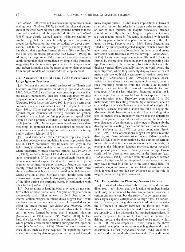
[44] Rifting in Iceland occurs as en echelon grabensassociated with fissure swarms. Regional dikes followingthe graben trend are fed by magma reservoirs rooted at acontinuous magma layer at �10 km depth. The magmareservoir also feeds magma chambers located at 2 km depththat in turn feed volcanoes and local sheet swarms [Gud-mundsson, 1990a, 1995b]. Field work and geophysical dataallowed Angelier et al. [1997] and Dauteuil et al. [2001] toinfer that most expansion at the surface occurs by tectonicstretching along tension fractures. At deep crustal levelsoceanic expansion is achieved through magma dilation ofthe regional dikes, and at intermediate crustal level by acombination of dike dilation and normal shear fracturesformed by downward propagation of tension fractures[Gudmundsson, 1992]. Figure 10 shows an aerial view ofthe Krafla fissure swarm, a typical rift zone graben inIceland, and an interpretation sketch of the volcanic-tectonic
infrastructure of the Icelandic rift zones. This model [Gud-mundsson, 1995b] provides relationships between tectonicstructures and magmatic plumbing that are consistent withobservations at modified narrow grabens on Mars as fromthe examples described in the present paper.
4.3. Comparison With the Asal Rift in Afar
[45] The Asal-Ghoubbet rift in Afar is another volcanicrift zone that may help understand the rifting process onMars. Structural interpretation of the Asal-Ghoubbet riftfrom Spot P imagery and offshore DEM (Figure 11a)reveals striking analogy with the Tempe Fossae (Figures11b and 11c). In both examples shown, strain has concen-trated around a central volcanic edifice located within thegraben (Figure 11e), which is a classical pattern predictedby stress models of overpressurized magma body in exten-sional setting [e.g., McKenzie et al., 1992]. Similar geom-etry (Figure 11d) has been observed at the slow spreadingNorth Atlantic mid-ocean ridge [Durand et al., 1995]. TheAsal-Ghoubbet rift results from the propagation of the slowspreading Aden oceanic rift on land [Manighetti et al.,1998]; therefore both the Afar and Atlantic examplessuggest that the rheology of the crust at low spreadingridges may be appropriate to the development of the TempeFossae rift geometry. Further comparison between riftpropagation from the Aden ridge to Afar and rift propaga-tion at Tempe Fossae on Mars is a promising topic that shallbe investigated in a forthcoming paper.[46] Fissure eruptions within the Asal-Ghoubbet rift occur
along graben parallel dikes [Le Dain et al., 1979] and arealigned with central volcanic edifices. Detailed analysis ofrelationships between tectonic structures and magmaticplumbing is underway [Doubre et al., 2001] and shouldhelp assessing comparison with models of Icelandic riftzones.
4.4. Qualitative Model of Volcanic Rifting on Mars
[47] The volcanic rift examples above help understandingthe relationships between surface tectonics and magmaticplumbing at Martian modified grabens. The terrestrialmodels are incorporated into the Martian context to proposea qualitative model of Martian rift structure. This model willthen be quantified using high-resolution DEMs andmechanical models.[48] Surface stretching started very early in the Martian
history and may even predate initiation of the Tharsisvolcanic province [Scott and Tanaka, 1986; Phillips et al.,2001]. There is very little evidence of alignment of major
Table 1. Viking Orbiter Images Used in DEM Generation
AreaMorphologic
TypeLatitude,
�NLongitude,
�WMax Length,
kmMax Width,
kmDepth,m
Volume,km3
1 Alba Patera catena (Tractus) 34.1 106.3 75 9 1600 4202 Mareotis Fossae small ovoid chasma 37.6 86.3 9 5 80 143 Mareotis Fossae narrow chasma 38.3 86 45 9 280 374 Mareotis Fossae narrow chasma 38.9 84.6 50 11 530 1305 Mareotis Fossae narrow chasma 39.2 84.2 35 14 1380 3486 Mareotis Fossae narrow chasma 39.3 83.7 35 14 1060 2327 Mareotis Fossae shallow ovoid trough 40.5 81.7 24 10 250 428 Valles Marineris (N Tithonium chasma) small chasma �3.5 90.2 13 11 560 449 SW Valles Marineris small chasma �7.8 90.2 22 14 1850 32410 SW Valles Marineris small chasma �7.8 89.8 20 15 1700 26511 SW Valles Marineris very small chasma �7.6 89.8 9 5 660 37
10 - 14 MEGE ET AL.: VOLCANIC RIFTING AT MARTIAN GRABENS

volcanic features (such as collapse pits, spatter ridges etc.)with grabens from this period (smaller-scale volcanic edi-fices are however observed at the Noachian Thaumasiagrabens; Figure 2b), consequently there is no evidence forsignificant interaction between magmatic and tectonic activ-ity [Mege and Masson, 1996]. Volcanic features areobserved to be associated with grabens of Hesperian and
Amazonian age, and are probably of the age of the lava flowsidentified in the Tharsis and Elysium regions [Scott andTanaka, 1986; Greeley and Guest, 1987]. This suggests thatboth extension and large-scale thermal anomalies in themantle were involved in the generated magmas when thegrabens formed. Evidence of gigantic magma volumes isprovided by: (1) the large range of Martian lithosphere
Figure 9. Analogy between morphology of segments I, Jn, and Js of the East Pacific Rise and grabenmorphology on Mars. (a) Digital elevation model of the East Pacific Rise. (b) Autonomous BenthicExplorer (ABE) digital elevation model along a portion of ridge segment Js (footprint 5 m), and ABEtracklines [Yoerger et al., 2000; Shah et al., 2003]. (c) Portion of a graben displaying a pit chain, AlbaFossae. Viking Orbiter image 252S18 centered at 118.49�W, 37.71�N, 74 m/pixel. (d) Linear trough atTractus Catena. Viking Orbiter image 254S49, 98.05�W, 35.67�N, 66 m/pixel. (e) Linear trough atLabeatis Fossae displaying evidence of fracture propagation. Viking Orbiter images 229A32 (94.34�W,22.33�N) and 229A34 (93.56�W, 22.61�N), 50 m/pixel. The boxes emphasize type areas displayingstrong interplanetary similarity.
MEGE ET AL.: VOLCANIC RIFTING AT MARTIAN GRABENS 10 - 15
thickness that allows voluminous partial melting by mantledecompression during extension, and consequently the veryhigh partial melting induced by any thermal anomaly, (2) theunforeseen thickness of lava flows observed over the whole2–10 km high Valles Marineris slopes [McEwen et al.,1999], which may give an idea of the thickness of the lavaflows that spread over the whole Tharsis, (3) the 60–80 kmthick crust in the Tharsis region [Zuber et al., 2000], whichemphasizes the efficiency of underplating and crustal thick-ening by intracrustal magma accretion.[49] Because the crust was undergoing extension simul-
taneous to magmatic activity, part of the generated magmawas trapped in regions of concomitant lithospheric stretch-ing. Whether part of this magma was channeled from the
area of maximum thermal anomaly depends mainly onlithosphere thickness [Mege and Masson, 1996; Kiefer,2000; Mege, 2001]. It is possible that the magma flowedlaterally from the central volcanic areas (Syria Planum,Tharsis Montes, Alba Patera, Elysium Mons) to the formingnarrow grabens. The mechanism involved would be analo-gous to magma channeling, from the hotspot center to riftsin the hotspot periphery, advocated at the Yellowstone/Columbia Plateau [Thompson and Gibson, 1991] andAfar/Tertiary frican rift systems [Ebinger and Sleep,1998]. The magmas would have been channeled andstocked below the grabens in magma chambers whose laterdeflation would have induced surface collapse. Alterna-tively, magmas may have been mainly generated underneath
Figure 10. (a) Aerial view of the Krafla fissure swarm in Iceland [after Opheim and Gudmundsson,1989] and (b) relationships between magma reservoirs, magma chambers, regional dike swarms, localsheet swarms, and surface fractures at typical Icelandic fissure swarms. Redrawn after Gudmundsson[1995b].
10 - 16 MEGE ET AL.: VOLCANIC RIFTING AT MARTIAN GRABENS

the grabens and migrated upward to feed the magmachambers. In both cases, surface eruptions would haveresulted from dikes propagating dominantly vertically fromthe chambers to the surface or subsurface.
[50] While tectonic stretching at surface was taking place,elongated magma chambers gradually emplaced at a deeperlevel (Figure 12a). The chambers may be discontinuousalong strike, reflecting observation that collapse features on
Figure 11. (a) Comparison between the Asal-Ghoubbet volcanic rift, Afar, from Spot P imagery of theAsal rift and a digital elevation model of the Ghoubbet basin from the data obtained during the Tadjouradencruise [Audin et al., 2001]; (b) and (c) part of the Tempe Fossae, Mars; (d) a segment of the North Atlanticmid-ocean ridge; and (e) summary of the basic common features. Spot P image KJ 144-327, 10m/pixel, andparts of NASA/JPL Viking orbiter image 704B54 centered at 71.98�W, 38.05�N, 213 m/pixel.
MEGE ET AL.: VOLCANIC RIFTING AT MARTIAN GRABENS 10 - 17

Mars are frequently observed as clusters separated byunaffected graben segments, and sometimes as en echelonsegments. This is similar to terrestrial rift zones, in whichmagma reservoir injects dikes both toward the surface andlaterally. There is no specific constraint on dike width in thismodel. Dike emplacement would have channeled magmaticfluids to upper levels, including the surface, inducing agradual pressure drop in the upper part of the reservoir andeventually surface collapse (Figure 12b). Collapse may haveoccurred along the dike fissures. Locally, dike propagationinto volatile-rich level may have induced hydrovolcanicexplosions and hydrothermal flows, whose repercussionsat the surface may have induced a number of small-scalevolcanic landforms, as discussed by Mege and Masson[1996] and following mechanisms investigated by Delaney[1982], Rubin [1993], and Bonafede and Olivieri [1995].[51] Many grabens display evidence of dramatic post-
faulting mass wasting that removed the border fault scarps(Figure 4d). This feature appears to be common to manysettings on Mars. The most spectacular evidence of large-scale postfaulting mass wasting is observed in the Vallesgraben system, where the period of major tectonic activitywas followed by intense landsliding of the walls and theremoval of fault scarps. The observations are consistent
with a period late in the geologic history of Mars wheresubsurface rocks lost part of their cohesion, favoring desta-bilization of the steepest slopes, maybe in relation topermafrost sublimation [e.g., Peulvast et al., 2001]. What-ever the origin of late stage mass wasting at the modifiednarrow grabens, mass wasting resulted in volume redistri-bution. In areas where the floor is flat and smooth (seen in�10 m resolution images), the late stage collapse event mayhave been accompanied by volcanic resurfacing followingring dikes. An illustration of possible modified grabensubsurface structure that underwent late stage mass wastingis given on Figure 13.[52] Apart from the troughs that underwent late stage
mass wasting, it is possible to retrieve the depth of the top ofthe deflating magma body, and its width, from experimentalmodels. Below we investigate these parameters undervarious conditions of remote stress and crustal rheology.Then numerical modeling of reservoir deflation will beperformed in order to determine physical parameters thatare consistent with the volumes of collapsed materials atsurface.
5. Magma Deflation: Experimental andNumerical Simulations
5.1. Experimental Modeling of Graben andTrough Evolution
5.1.1. Apparatus[53] Garel [1998], Lagabrielle et al. [2001], and Garel et
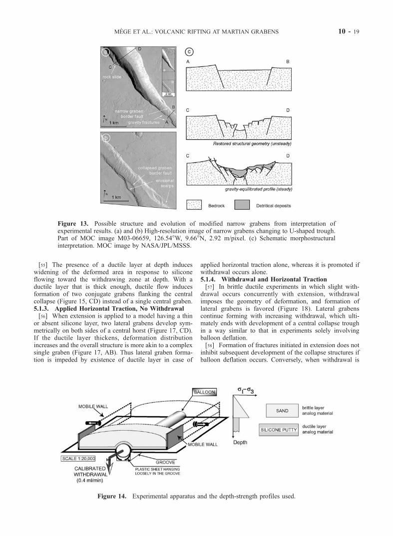
al. [2002] carried out small-scaled experimental modelingof magma chamber deflation, in brittle and brittle ductilelayers, some of them combined with horizontal extension.These experiments could provide useful insights into thedevelopment of surface features during magma deflation aswell as the depth of the deflating body. The scale, fixed at1:20,000, was based on the equality between no-dimen-sional values of the model and of the natural prototype[Hubbert, 1937]. The experimental apparatus used in thepresent study includes an inflatable elongated balloon filledwith water and set in a central groove in a table as ananalogue of the magma reservoir (including magma lensand crystal mush) (Figure 14). Balloon deflation is con-trolled through a pipe closed by a tap. In some experimentsthe balloon is capped with a silicone layer of thickness Ebrepresenting hot rocks below the ductile/brittle transition(DBT), and is covered by a sand layer of thickness Edaccounting for the upper brittle crust. In other experimentsthe ductile layer is absent. Experiments integrate either orboth balloon withdrawal and extension at the lateral boun-dary of the model by means of two mobile walls.5.1.2. Withdrawal, No Applied Horizontal Traction[54] Significant balloon deflation, without extension in a
wholly brittle layer, results in the formation of a centralcollapse trough limited by reverse faults that are embeddedwithin a wider graben (Figure 15, AB). In surface view, thetrough trace follows the shape of the balloon at depth. Crosssections reveal that the faults are rooted at the edges of thedeflating area. Experiments conducted at various balloondiameters show that reservoir depth is proportional tograben width whereas it is inversely proportional to collapsetrough width (Figure 16). Similar results have been obtainedin other experiments carried out by Roche et al. [2000].
Figure 12. Qualitative sequence of magmatic-tectonicdevelopment at Martian modified grabens.
10 - 18 MEGE ET AL.: VOLCANIC RIFTING AT MARTIAN GRABENS
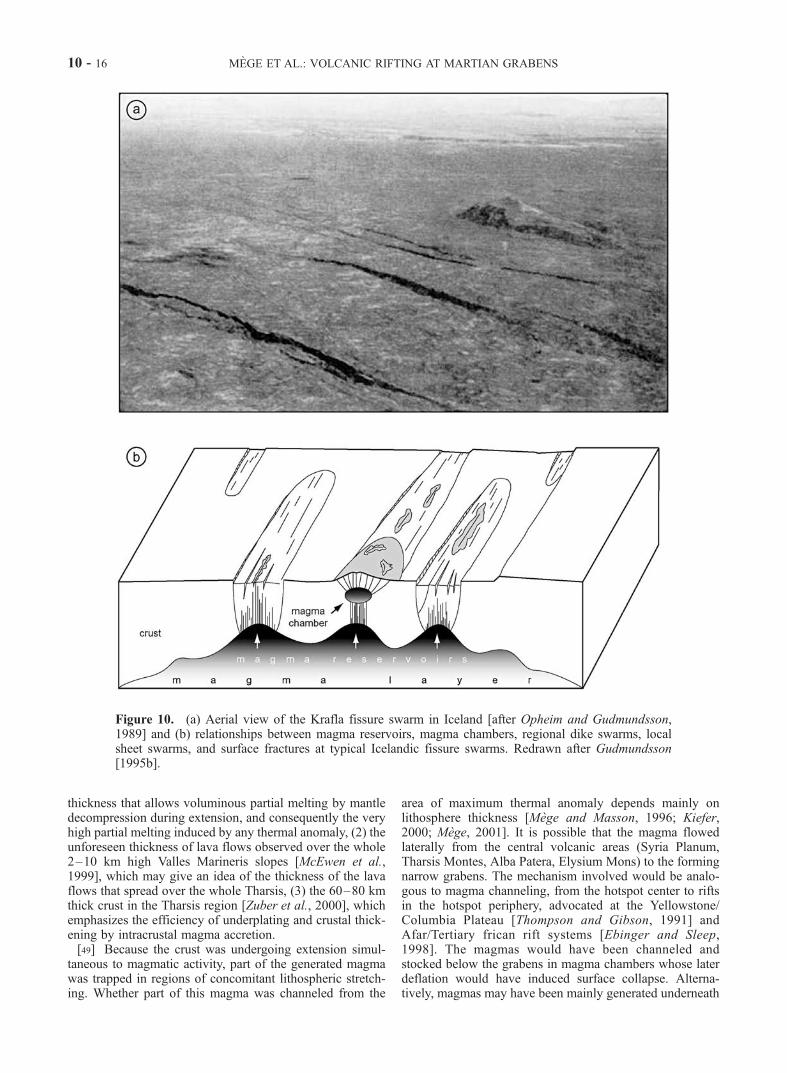
[55] The presence of a ductile layer at depth induceswidening of the deformed area in response to siliconeflowing toward the withdrawing zone at depth. With aductile layer that is thick enough, ductile flow inducesformation of two conjugate grabens flanking the centralcollapse (Figure 15, CD) instead of a single central graben.5.1.3. Applied Horizontal Traction, No Withdrawal[56] When extension is applied to a model having a thin
or absent silicone layer, two lateral grabens develop sym-metrically on both sides of a central horst (Figure 17, CD).If the ductile layer thickens, deformation distributionincreases and the overall structure is more akin to a complexsingle graben (Figure 17, AB). Thus lateral graben forma-tion is impeded by existence of ductile layer in case of
applied horizontal traction alone, whereas it is promoted ifwithdrawal occurs alone.5.1.4. Withdrawal and Horizontal Traction[57] In brittle ductile experiments in which slight with-
drawal occurs concurrently with extension, withdrawalimposes the geometry of deformation, and formation oflateral grabens is favored (Figure 18). Lateral grabenscontinue forming with increasing withdrawal, which ulti-mately ends with development of a central collapse troughin a way similar to that in experiments solely involvingballoon deflation.[58] Formation of fractures initiated in extension does not
inhibit subsequent development of the collapse structures ifballoon deflation occurs. Conversely, when withdrawal is
Figure 13. Possible structure and evolution of modified narrow grabens from interpretation ofexperimental results. (a) and (b) High-resolution image of narrow grabens changing to U-shaped trough.Part of MOC image M03-06659, 126.54�W, 9.66�N, 2.92 m/pixel. (c) Schematic morphostructuralinterpretation. MOC image by NASA/JPL/MSSS.
Figure 14. Experimental apparatus and the depth-strength profiles used.
MEGE ET AL.: VOLCANIC RIFTING AT MARTIAN GRABENS 10 - 19

followed by extension, the collapse structures widen inresponse to outward migration of the deformation wave.5.1.5. Graben Width and Central Trough WidthVersus Magma Chamber Width and Depth[59] The experimental results provide elements for esti-
mating magma body width and depth from surface obser-vations, which is helpful for planetary bodies wheresubsurface data are unavailable. Grabens displaying aninner central trough that form when significant withdrawaloccurs (in wholly brittle crust under no or limited appliedtraction; see Figures 15 and 16) are especially useful. In theexperiments the faults have changing dip angles with depth,in agreement with natural examples in which dip anglevaries according to lithostatic pressure field [e.g., Odonne etal., 1999]. For simplicity, if faults are assumed to be planar,then the depth of the deflating body is obtained from centraltrough width Wc, the graben width Wg, the brittle layerthickness e, and the drained area width B using relations
Wg ¼ Bþ 2e= tan b
Wc ¼ B� 2e= tanað1Þ
where a is reverse fault dip and b normal fault dip. Thesystem of equations (1) can be solved for e:
e ¼ kWg �Wc
2ð2Þ
where k = (tan a tan b)(tan a + tan b). In the experiments,commonly found mean dip angles are a � 85 and b � 50,suggesting an approximation for equation (2):
e � 0:54 Wg �Wc
� �ð3Þ
Combining equations (1) and (2) shows that B and e can becalculated separately:
B ¼ Wg þWc
2� k 0
Wg �Wc
2ð4Þ
where k0 = (tan a � tanb)(tan a + tan b). Using a � 85 andb � 50,
B � 0:094Wg þ 0:91Wc ð5Þ
Figure 15. Results of scaled deflation experiments in brittle (Mohr-Coulomb) and brittle ductile (Mohr-Coulomb-Newtonian viscous) materials with no horizontal traction: (a) rheologic cross section (bottom tothe right), Eb, brittle layer thickness and Ed, ductile layer thickness; (b) surface view at the end of theexperiment and location of cross sections; and (c) cross sections at the end of the experiment. Kinematicsand sequence of fault development are indicated.
Figure 16. Width of collapse troughs and grabens versus initial depth of deflated body (balloon) in puredeflation experiments with no silicone layer. Values are normalized to balloon diameter.
10 - 20 MEGE ET AL.: VOLCANIC RIFTING AT MARTIAN GRABENS

Examples of the application of equations (3) and (5) tonarrow grabens will be given below.5.1.6. Sequence of Fracture Development and Collapse[60] In withdrawal experiments in a brittle medium ana-
log (with no horizontal traction; see Figure 15, AB), thecollapse trough initiates after 15–35% withdrawal and isfollowed by outward propagation of stepping normal faultson both trough sides. After 45–65% withdrawal the max-imum breadth of the deformed area is attained and thewhole strain is achieved by slipping along the outermostborder faults. Conversely, in horizontal traction experimentsin a brittle analog medium (Figure 17, AB), once lateralgrabens have synchronously initiated then deformationmigrates inward by activation of new faults between theoutermost normal faults.[61] In brittle ductile analog experiments in which con-
jugate grabens are created (Figure 15, CD, and Figure 18)the lateral grabens form in response to inward ductile flowbefore central collapse occurs. No preferential fault devel-opment sequence has been found in ductile analog experi-ments (Figure 17, CD).5.1.7. Interpretation of a Ductile Layer inExperimental Models[62] Experimental results emphasize that the presence of a
ductile layer between the magma body and the upper brittlecrust tends to increase surface strain distribution (Figures19a, 19c, and 19e), which is in agreement with many earlierstudies showing that strain distribution depends on brittlecrust thickness [e.g., Vendeville et al., 1987; Allemand and
Brun, 1991]. In experimental models including a ductilelayer in which twin grabens are observed to form, thelocation of the grabens is related to the width of the grooveand to the ductile layer thickness. In pure extension experi-ments, a very thin or absent ductile layer must be imposedto generate two conjugate grabens (Figure 19b), whosebounding faults are rooted at the edges of the groove.Therefore, in this case, graben location directly dependsupon groove width. The zone comprised between the faultanchor points represent a null deformation area equivalentin the wild to a stress free boundary that does not transmitlithospheric stresses. Along an oceanic ridge axis, a magmalens located at the upper part of a magma reservoir (or aductile lower crust) may behave this way [Chen andMorgan, 1990; Goff, 1991; Shaw and Lin, 1996; Eberleand Forsyth, 1998]. Therefore the experimental modelscontaining a ductile layer may be compared to either abrittle ductile crustal rheology, or a brittle crust rheology,provided that the magma reservoir is capped with a magmalens.5.1.8. Surface Evidence of Magma WithdrawalDirection[63] In deflation experiments, lateral liquid migration
during withdrawal produces V-shaped normal fault tracesaround the collapse trough, with the V tip oriented towardthe direction of drainage. Similar patterns are observed atpropagating oceanic ridges during along-axis melt lensmigration at the top of a crustal reservoir [Hey et al.,1989]. Their formation mechanism remains poorly under-
Figure 17. Results of scaled horizontal traction experiments (rate 1 cm/h during 2h30’) with nowithdrawal: (a) rheologic cross section, (b) final surface view, and (c) final cross sections. Sequence offaulting: faults active at the end of experiment are displayed in bold; the earlier faults are displayed withthin lines.
Figure 18. Results of a scaled experiment combining simultaneous extension and limited withdrawal:(a) final surface view and (b) final cross section. Further withdrawal induces subsequent collapse troughformation in a way similar to deflation experiments with no horizontal traction.
MEGE ET AL.: VOLCANIC RIFTING AT MARTIAN GRABENS 10 - 21

stood, however the experimental results reported here sug-gest that V-shaped fault trace may be interpreted as anindicator of magma flow, i.e., when a magma fraction in anoverpressurized reservoir invades the fracture of a new ridgesegment this results in a limited reservoir deflation.5.1.9. Mass Wasting[64] Landsliding is common to every deflation experi-
ment because of the unstable hanging wall of the trough-bounding reverse faults. This was also been featured inother experiments [Roche et al., 2000]. Trough broadeningby mass wasting along fault scarps is thus a major mech-anism of graben and trough evolution.
5.2. Application to Modified Narrow Grabens
[65] Modified grabens affected by collapse pits andtroughs, U-shaped troughs, and narrow chasmata may beexplained by several of the mechanisms described above.5.2.1. Pit-and-Trough Chains[66] Pit-and-trough chains may form by any mechanism
provided that deflation occurs (Figures 19c–19e). Pit-and-trough chains not associated with grabens may result fromlimited deflation in a non/weakly deviatoric remote stressfield (Figure 19d, 1). Those observed within a graben mayform by continuing deflation (Figure 19d, 2) or in a strongerextensional stress field (Figure 19e, 2). Because of theuncertainty of surface interpretation arising from erosionalprocesses and volcanic activity, and the absence of data forconstraining heat flow when the tectonic structures formed,it is hard determining if the DBT was below or above themagma reservoir. Most chains of pits and troughs do notrequire the DBT to be higher than the top of the reservoir.[67] Figure 20 shows examples of pit-and-trough chains
within single grabens displaying inverse proportionalitybetween graben width and the width of central pits andtroughs. These examples match the experimental results inwhich deflation occurs in absence of remote extension and ofa ductile layer between the deflating body and the surface.The observation that many pit-and-trough chains are notassociated with grabens, is also in agreement with experi-ments in which graben formation occurs (Figure 19d, 2) onlyif deflation continues after the central collapse trough hasformed (Figure 19d, 1). Equations (2) and (4) allow theestimation of depth and width of the deflating body in caseswhere the geometry of the central trough and the graben has
remained close to pristine. An idea of the depth and widthmay be given by application of equations (3) and (5).Applying these equations to the Noctis Labyrinthus example(Figure 20a) the depth of the top of the magma body is foundto vary between 3.6 km and 6.7 km, and its width between4.1 and 7.7 km. In the Alba Patera area (Figure 20b) they arefound to be within the range 0.2–1 km, and 0.7–1.5 kmrespectively. In both cases these magma bodies are inter-preted to be only the upper part of the magmatic plumbingfeeding the flood lavas. The Noctis Labyrinthus exampleshows that subsequent deflation of a deeper magma bodyinduces late stage and broader-scale collapse. This observa-tion may be extrapolated to the whole Noctis Labyrinthusarea, where the labyrinthus corridors (who display alignedpits and troughs), may connect deeper intrusions formingcorridor intersections. The Noctis Labyrinthus plumbingsystem would then resemble that of extensional margins inhotspot setting, such as the North Atlantic volcanic provinceduring the early history of the Tertiary Thulean mantle plume[Callot et al., 2001].5.2.2. Small Chasmata and Linear U-shaped Troughs[68] Small chasmata are significantly wider and deeper
than pits and troughs. Because of the one order of magni-tude larger collapsed volume observed, small chasmata arethought to result from deflation of a larger and deepermagma body than the magma bodies inferred for pits andtroughs. However, in detail the width and depth of themagma body cannot be estimated because initial depressiongeometry has been removed by wall erosion (see anexample on Figure 21). Similarly, linear U-shaped troughsmay not be used to infer magma body geometry at depth.The numerical approach, below, may nevertheless helpconstrain physical parameters for their formation.[69] In areas where pit-and-trough chains and narrow
chasmata are combined, two magma bodies may berequired. The deepest level may be the NBZ or the DBT,whereas the shallowest may be a stress barrier at whichupward propagating dikes turn to sills that gradually build ashallow depth magma chamber [e.g., Gudmundsson,1990b].5.2.3. Tectonic Patterns Involving ShallowDuctile Layer[70] In many instances, observations at modified grabens
are not inconsistent with interpretation of a shallow ductile
Figure 19. Synthesis of surface structures expected from the experimental results of graben andcollapse trough development as a function of deflation, remote stress field, and ductile crust thicknessabove the reservoir. Lower fault tips are not displayed. Numbers refer to the sequence of events. Arrowsindicate the main direction of displacement.
10 - 22 MEGE ET AL.: VOLCANIC RIFTING AT MARTIAN GRABENS

layer, or possibly a magma body that has undergone partialwithdrawal only, but such a ductile level is not required.Existence of a ductile layer is expected to result in dis-tributed strain. In general, the broadest modified narrowgrabens and the chasmata have been extensively eroded andmost clues to their geometry prior to erosion have beenremoved. Nevertheless, there are several examples wherethe observed strain distribution suggests existence of a
shallow ductile layer. Twin grabens aligned with U-shapedtrough and pit chains are not frequent but detailed analysisof MGS and Viking imagery has revealed examples invarious areas of Mars, some of which are illustrated onFigures 22a, 22b, 22d, and 22e. On Figure 22c the geometryof a major regional graben system, Tempe Fossae, has beeninfluenced by local stress fields, at least one of which haveprobably been induced by local magma centers. Strain
Figure 20. (a) Surface interpretation in southeast Noctis Labyrinthus. The arrow indicates direction ofmagma flow and graben propagation from the orientation of the two oblique normal faults nearby (seeFigure 23). Part of NASA/JPL Viking Orbiter image 47A20 centered at 99.71�W, 10.14�S, 105 m/pixel.(b) Similar observations at Labeatis Fossae. NASA/JPL Viking Orbiter image 229A23, 52 m/pixel,92.05�W, 24.12�N. (c) Schematic interpretations of profiles AB and CD in Figures 20a and 20b fromexperimental results in which deflation of a magma body occurs in a brittle crust with negligible remoteextension (Figures 15 and 19d).
MEGE ET AL.: VOLCANIC RIFTING AT MARTIAN GRABENS 10 - 23

distribution over a broad area suggests existence of ashallow ductile layer, which is supported by results of riftflank uplift inversion and gives a � 10 km thick elasticlithosphere in this area [Wilkins and Schultz, 2001].[71] Figure 21 shows a chasma from the Elysium Fossae
that displays structural remnants suggestive of a distributeddeformation event prior to extensive erosion. It demon-strates that despite present simple morphology, chasmatamay have initiated as broad extensional systems that laterunderwent broad-scale collapse and wall retreat. Distributeddeformation at chasmata may have resulted from deflationof a widespread underlying magma body mechanicallyacting as a ductile layer underneath the brittle crust.
5.2.4. Direction of Magma Flow[72] V-shaped fault profiles are observed in the Alba
Patera and Noctis Labyrinthus areas. Figure 23 shows anexample of a V-shaped fault profile at a Martian graben thatmay be interpreted as an indicator of magma flow duringreservoir withdrawal. From analogy with terrestrial analogsat propagating rifts, this geometry might indicate the direc-tion of magma propagation within the crust and grabenopening. The magma body underlying the grabens isthought to have propagated from the Tharsis central area[Mege and Masson, 1996], which is in agreement with theorientation of the V tip. Another example can be found atthe Noctis Labyrinthus given on Figure 20a.
5.3. Numerical Modeling of Withdrawn MagmaVolume
[73] The magnitude of deflation that induced surfacecollapse may be numerically investigated by comparingthe volume of the deflated magma and the volume of thevoid generated at surface. Figure 24 shows two end-mem-bers volume transfer mechanisms that are accounted for inthe models. In a closed system, the whole magma body isthe deflated lens, and there is no magma replenishment. Inan open system, the magma lens is connected with areservoir that begins replenishing as soon as significantmagma underpressurization occurs (Figure 24). In the firststep, limited crustal stretching traps magma at depth, whichin turn leads to overpressure in the magma lens and helpsfocus tectonic strain at surface (step 1). Dike emplacement(not shown on Figure 24) occurs between the magma lensand the surface in such a way that the total dilation remainsvertically constant. Gradually magma overpressure decrea-ses (step 2). As long as magma pressure is positive, theerupted magma volume does not decrease the magma lensvolume, and there is no surface collapse. When the magmapressure falls below zero, the differential stress in the hostrock increases to a critical value sc equal to rock strength(step 3). Then the whole host rock body above sc fails andcollapses into the deflated lens (step 4). The volume ofthe unstable host rock may be equal to the volume of thecollapse trough that eventually forms at surface. In theclosed system considered, the volume of destabilized hostrock material as deduced from the volume of the surfacetrough is thus a direct measure of the deflation magnitude.
Figure 21. Shallow chasma in Elysium Fossae. Initialchasma structure remnants are observed within the chasma,but retrieving initial chasma geometry is much toospeculative to be used to infer the geometry of subsurfacemagma body. Note that the internal structures may beinterpreted as a series of tilted blocks aligned with the borderfaults observed southeast of the chasma. Initial chasmastructure might be a wide rift developed in a crust having ashallow ductile layer. U-shaped troughs parallel to thechasma suggest existence of a dike or another linear magmabody parallel to the magma body underneath the chasma butshallower. Part of NASA/JPL Viking Orbiter Image VO541A24 centered at 220.02�W, 29.44�N, 152 m/pixel.
Figure 22. (opposite) Possible surface structures denoting shallow ductile layer. (a) Central trough surrounded by lateralgrabens at Tractus Catena (part of MOC image M03-06623 centered at 101.26�W, 33.32�N, 3.04 m/pixel). This pattern isobserved in experimental results when the top of the ductile layer lies above the top of the magma body (Figures 19c, 2,and 19e, 2). (b) The same at Labeatis Fossae (part of Viking Orbiter images 229A32-34 centered at 94.34�W, 22.33�N, 50m/pixel). The geometry of rift segment tips gives direction of magma propagation [e.g., Sempere and Macdonald, 1986].(c) Distributed stretching is also featured in shallow ductile layer experiments in extensional stress field (Figures 19a and19e). Grabens at Tempe Fossae fanning around central volcanic edifice suggests existence of a shallow ductile layer duringmagmatic deflation [see, e.g., McKenzie et al., 1992]. Viking Orbiter image 704B54 centered at 71.98�W, 38.05�N, 213m/pixel. (d) Grabens displaying an internal horst are locally observed at Labeatis Fossae, northwest Figure 22b. A parallelgraben of similar geometry displays central troughs, suggesting that the graben formed above a weakly deflating magmabody while the remote stress was extensional (Figure 19e). Part of Viking Orbiter image 662A67 centered at 95.26�W,22.59�N, 33 m/pixel. (e) Same observations at Gordii Fossae. Note in passing that the graben in the western part of themosaic displays two major border faults and two internal pit-and-trough chains, which is not consistent with the hypothesisthat the graben formed in response to the driving pressure of a single emplacing dike. Part of Viking Orbiter images 659A14(124.51�W, 17.82�N) and 659A16 (124.48�W, 17.32�N), 40 m/pixel. MOC images by NASA/JPL/MSSS, Viking Orbiterimages by NASA/JPL.
10 - 24 MEGE ET AL.: VOLCANIC RIFTING AT MARTIAN GRABENS
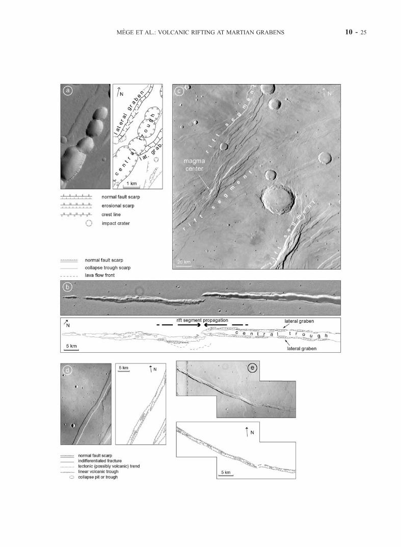
MEGE ET AL.: VOLCANIC RIFTING AT MARTIAN GRABENS 10 - 25
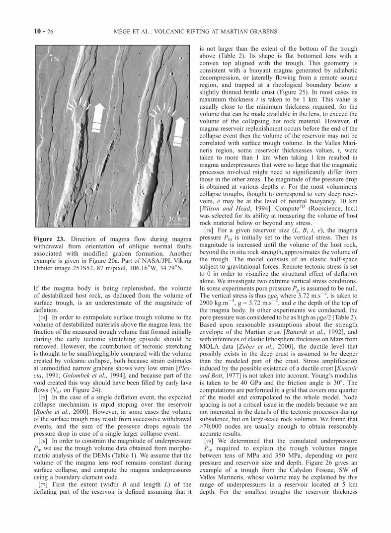
If the magma body is being replenished, the volumeof destabilized host rock, as deduced from the volume ofsurface trough, is an underestimate of the magnitude ofdeflation.[74] In order to extrapolate surface trough volume to the
volume of destabilized materials above the magma lens, thefraction of the measured trough volume that formed initiallyduring the early tectonic stretching episode should beremoved. However, the contribution of tectonic stretchingis thought to be small/negligible compared with the volumecreated by volcanic collapse, both because strain estimatesat unmodified narrow grabens shows very low strain [Ples-cia, 1991; Golombek et al., 1994], and because part of thevoid created this way should have been filled by early lavaflows (Ve1 on Figure 24).[75] In the case of a single deflation event, the expected
collapse mechanism is rapid stoping over the reservoir[Roche et al., 2000]. However, in some cases the volumeof the surface trough may result from successive withdrawalevents, and the sum of the pressure drops equals thepressure drop in case of a single larger collapse event.[76] In order to constrain the magnitude of underpressure
Pm we use the trough volume data obtained from morpho-metric analysis of the DEMs (Table 1). We assume that thevolume of the magma lens roof remains constant duringsurface collapse, and compute the magma underpressuresusing a boundary element code.[77] First the extent (width B and length L) of the
deflating part of the reservoir is defined assuming that it
is not larger than the extent of the bottom of the troughabove (Table 2). Its shape is flat bottomed lens with aconvex top aligned with the trough. This geometry isconsistent with a buoyant magma generated by adiabaticdecompression, or laterally flowing from a remote sourceregion, and trapped at a rheological boundary below aslightly thinned brittle crust (Figure 25). In most cases itsmaximum thickness t is taken to be 1 km. This value isusually close to the minimum thickness required, for thevolume that can be made available in the lens, to exceed thevolume of the collapsing hot rock material. However, ifmagma reservoir replenishment occurs before the end of thecollapse event then the volume of the reservoir may not becorrelated with surface trough volume. In the Valles Mari-neris region, some reservoir thicknesses values, t, weretaken to more than 1 km when taking 1 km resulted inmagma underpressures that were so large that the magmaticprocesses involved might need to significantly differ fromthose in the other areas. The magnitude of the pressure dropis obtained at various depths e. For the most voluminouscollapse troughs, thought to correspond to very deep reser-voirs, e may be at the level of neutral buoyancy, 10 km[Wilson and Head, 1994]. Compute3D (Rocscience, Inc.)was selected for its ability at measuring the volume of hostrock material below or beyond any stress.[78] For a given reservoir size (L, B, t, e), the magma
pressure Pm is initially set to the vertical stress. Then itsmagnitude is increased until the volume of the host rock,beyond the in situ rock strength, approximates the volume ofthe trough. The model consists of an elastic half-spacesubject to gravitational forces. Remote tectonic stress is setto 0 in order to visualize the structural effect of deflationalone. We investigate two extreme vertical stress conditions.In some experiments pore pressure Pp is assumed to be null.The vertical stress is thus rge, where 3.72 m.s�2, is taken to2900 kg.m�3, g = 3.72 m.s�2, and e the depth of the top ofthe magma body. In other experiments we conducted, thepore pressure was considered to be as high as rge/2 (Table 2).Based upon reasonable assumptions about the strengthenvelope of the Martian crust [Banerdt et al., 1992], andwith inferences of elastic lithosphere thickness on Mars fromMOLA data [Zuber et al., 2000], the ductile level thatpossibly exists in the deep crust is assumed to be deeperthan the modeled part of the crust. Stress amplificationinduced by the possible existence of a ductile crust [Kusznirand Bott, 1977] is not taken into account. Young’s modulusis taken to be 40 GPa and the friction angle is 30�. Thecomputations are performed in a grid that covers one quarterof the model and extrapolated to the whole model. Nodespacing is not a critical issue in the models because we arenot interested in the details of the tectonic processes duringsubsidence, but on large-scale rock volumes. We found that>70,000 nodes are usually enough to obtain reasonablyaccurate results.[79] We determined that the cumulated underpressure
�Pm required to explain the trough volumes rangesbetween tens of MPa and 350 MPa, depending on porepressure and reservoir size and depth. Figure 26 gives anexample of a trough from the Calydon Fossae, SW ofValles Marineris, whose volume may be explained by thisrange of underpressures in a reservoir located at 5 kmdepth. For the smallest troughs the reservoir thickness
Figure 23. Direction of magma flow during magmawithdrawal from orientation of oblique normal faultsassociated with modified graben formation. Anotherexample is given in Figure 20a. Part of NASA/JPL VikingOrbiter image 253S52, 87 m/pixel, 106.16�W, 34.79�N.
10 - 26 MEGE ET AL.: VOLCANIC RIFTING AT MARTIAN GRABENS

needs to be > 2 km for the volume of the host rock abovefailure not to exceed the volume of the reservoir and henceallow trough formation in a single collapse event withnegligible reservoir replenishment. This results from thelower width/depth ratio for small troughs than for morevoluminous troughs such as chasmata. The reservoir belowthe smallest measured trough (12 on Table 2) needs to beat >3–4 km thick. This is based upon the assumption thatthe reservoir width (top 1 km at the top, 2 km at thebottom) is on the order of the trough width (1 km). Itwould still require a reservoir at least 2 to 3 km thick ifreservoir width 2 km (top) to 5 km (bottom).
6. Conclusion
[80] Ubiquitous pits and troughs at Martian grabens areshown to be key features for understanding the volcanic andtectonic graben evolution. Step by step, searching for theirformation has lead to suggest a mechanism of grabenevolution akin to volcanic tectonic models of terrestrialrifting. Using either MOLA data or combination of MOLAdata and Viking Orbiter stereoscopic images, the volumes ofremoved material at individual troughs and chasmata are onthe order of tens to hundreds of km3. The volume of somesmall chasmata in the Tharsis and Elysium regions, thoughtto be of similar origin, probably attains one thousand km3 ormore. The volume of pit craters is smaller though not
measurable using the current altimetry and topography data.The large volumes we found probably proscribe a mecha-nism of pressure drop above single dikes (or sinking in othermode I fractures), and make necessary emplacement andsubsequent deflation of magma reservoirs beneath the gra-bens. The huge quantity of magma required to feed suchreservoirs can be readily obtained by mantle adiabaticdecompression and the thermal anomalies that have beeninvolved in large Martian volcanic igneous provinces build-ing [Mege and Masson, 1996; Mege, 2001], assuming thatthe present-day crustal thicknesses, 50 km on average [Zuberet al., 2000], are not smaller than when the grabens andtroughs formed. The reservoirs were trapped in the regionsof ongoing tectonic thinning and have thus an elongatedshape. Reservoir underpressurization, up to 350 MPa ormore, is inferred from numerical simulation of reservoirdeflation. These values may have been reached either bysingle catastrophic withdrawal events followed by stoping,or by successions of small-scale deflation events, forinstance corresponding to dike emplacement. The depth ofthe reservoirs beneath the grabens displaying pits andtroughs can be inferred from surface observations. We didnot carry out a global survey, but in representative areas ofAlba Patera and Noctis Labyrinthus we found that magmareservoirs might lie at �1 km and�5 km depth respectively,and have widths in the same range. Theoretical consider-ations based on neutral buoyancy zone modeling [Wilson
Figure 24. Volume transfers inducing surface collapse as modeled in the numerical experiments.
MEGE ET AL.: VOLCANIC RIFTING AT MARTIAN GRABENS 10 - 27

and Head, 1994] suggest that 10 km should be anotherpreferential depth for magma ponding. However, only anexhaustive graben and trough survey can determine whetherpreferential depths of magma body emplacement exist atTharsis, Elysium, or global scale.[81] Dike injection from the reservoirs is actually a
reasonable means to channel the magma to the surface.This study confirms earlier studies suggesting that dikeswarms should exist on Mars, but it is likely that everygraben displaying aligned volcanic morphologic featuresshould have its own dike swarm(s), for example, similar tothe dikes in the Icelandic fissure swarms. Strictly speaking,these dike swarms are thus not akin to the terrestrial giantmafic dike swarms. They are shorter and probably thinner,and it is likely that a number of them, emplaced late in thereservoirs’ history, carried acidic magmas differentiated in
the reservoirs. Also they are fed from below, in contrary to anumber of giant dike swarms that appear to have been fedfrom central magma chambers [e.g., Ernst and Baragar,1992]. Nevertheless, at the scale of the large igneousprovince they are observed in, they may be viewed asdikelets, and the feeding reservoirs may be viewed asequivalent to giant mafic dikes [Ernst et al., 2001] andmay have emplaced in part vertically (in response to mantledecompression) and in part laterally (channeling from thecentral part of the igneous province [Thompson and Gibson,1991; Sleep, 1994b]). Magma propagation would occur at aspeed depending on magma decompression and tectonicactivity timescales, i.e., much lower than magma propaga-tion in dikes [e.g., Rubin, 1995].[82] Because of the difference in magma emplacement
mechanism, there is little chance that the dikes have playeda significant role in surface fracturing by way of magmapressure. This inference also applies to other terrestrialplanets because it is based on detailed examination ofterrestrial evidence and mechanical models in addition toMartian evidence. It is possible though that some dikes, asmechanical discontinuities, may have been involved in thelocation of surface fractures during the early phase offracture initiation [see also Koenig and Pollard, 1998].[83] Magmatic deflation not only explains the occurrence
of pits and troughs in grabens, it may also contribute to theinitiation and development of graben border faults. Theremight also be cases where volcanically modified grabensformed entirely in response to magmatic deflation with noinfluence of regional stress.
Appendix A: Method for the Calculation ofDepression Volumes
[84] To measure the depressions we use two types ofDEMs. The first type combines accuracy of MOLA altim-etry data and spatial resolution of stereo-derived VikingDEMs (Figure 7). Baratoux et al. [2001] have describedanother method combining these two data sets. The secondtype is from extrapolation of MOLA data only. Such DEMswere used for studying collapse features in areas wherethere is no Viking stereo coverage or where the spatialresolution of Viking stereo derived DEMs would have beeninsufficent.[85] In order to achieve a spatial resolution exceeding that
of the currently available MOLA [Smith et al., 2001]derived DEM (1/32� per pixel or �1.864km/pixel), weneeded to produce DEMs from stereo imagery yielding aspatial resolution of �1.8 km/pixel or finer. In view of therequirement of our stereo matching software, ‘‘Gotcha’’[Day et al., 1992], that uses typically a correlation patchdiameter of �20 pixels for most areas on Mars, this limitspotentially useful stereo pairs to images of <90 m/pixelresolution. A search was made in several sites displayingmodified narrow grabens of major interest using a stereocoverage program [Cook et al., 1992] for Viking Orbiter[Snyder, 1977] images; ten stereo pairs were found (Table 3).The first two pairs were selected because they were com-parable in resolution to the 90 m/pixel threshold, theremaining pairs were chosen because they were well belowthe above threshold and covered the regions of interest.However, 627A21:627A04 and 627A23:627A02 were sub-
Table 2. Reservoir Parameters Consistent With Observed Trough
Volumesa
N�L,km
B,km
e,km
t,km
sc,MPa
Pp/Pl,MPa
�Pm,MPa
Vt,km3
1 75 5 5 1 53 0 �145 4205 1 26 0.5 �6010 1 105 0 �23510 1 53 0.5 �85
2 8 2 2 1 21 0 �80 142 1 10.5 0.5 �405 1 53 0 �1705 1 26 0.5 �80
3 40 5 5 1 53 0 �85 375 1 26 0.5 �3210 1 105 0 �13010 1 53 0.5 �30
4 40 5 5 1 53 0 �120 1305 1 26 0.5 �4510 1 105 0 �19010 1 53 0.5 �120
5 30 5 5 1 53 0 �180 3485 1 26 0.5 �7010 1 105 0 �30010 1 53 0.5 �110
6 30 5 5 1 53 0 �155 2325 1 26 0.5 �6510 1 105 0 �26010 1 53 0.5 �95
7 20 5 5 1 53 0 �100 425 1 26 0.5 �4010 1 105 0 �16010 1 53 0.5 �45
8 13 1 2 2 21 0 �100 442 2 10.5 0.5 �305 2 53 0 �1405 2 26 0.5 �30
10 20 5 5 1 53 0 �205 3245 1 26 0.5 �8510 1 105 0 �34510 1 53 0.5 �135
11 20 10 5 1 53 0 �105 2655 1 26 0.5 �3010 1 105 0 �17010 1 53 0.5 �45
12 10 2 5 4 53 0 �190 375 4 26 0.5 �7510 4 105 0 �31510 4 53 0.5 �115
aPl: lithostatic pressure, Pp: pore pressure, �Pm: sum of the magmaunderpressures required for producing the observed trough volumes, sc:critical failure stress using the strength envelope for Mars given by Banerdtet al. [1992]. Magma underpressure accuracy is ±5 MPa.
10 - 28 MEGE ET AL.: VOLCANIC RIFTING AT MARTIAN GRABENS

sequently eliminated because of having too small an area ofoverlap. The theoretical height accuracy for a singlematched point can be calculated using the formula fromCook et al. [1992]:
A ¼ Max Ið Þ C
B=HðA1Þ
where A is the theoretical height accuracy (m), Max (I) isthe maximum resolution of either of the two images in astereo pair (m), C is the precision to which image coordinatemeasurements can be made - assumed to be C = 1.0 forvidicon images, and B/H is stereo pair base separation tomean height ratio.[86] The ability to resolve these theoretical relative
heights depends upon how well the patch-based correlationmatcher can lock onto surface texture. In the presence ofpoorly textured plains, or poor signal-to-noise ratio sectionsof images, image noise may increase C. On high contrast,high textured surfaces, C may be smaller and hence improve
the ability to resolve finer heights. In addition, by combin-ing many close point measurements together in a data bin, afiner height accuracy can be achieved. Therefore the theo-retical height accuracy should be regarded as a means tocompare and identify suitable stereo pairs. In comparisonthe 1/32� MOLA DEM, although constructed from individ-ual MOLA points with absolute height accuracies of ±30 mand relative accuracies of ±0.3 m [Smith et al., 2001], hasbeen constructed by interpolating between MOLA pointswith an along track spacing of �330 m and an across trackspacing of �1.8 km. Consequently the MOLA DEM willnot have anywhere near the same relative and absoluteheight accuracy of individual altimeter points except on flatsurfaces. Viking stereo DEMs have the advantage of moreheight points per unit area, albeit not of the same accuracyas individual MOLA points.[87] The Viking Orbiter vidicon images were processed
initially to correct geometrically for camera distortion,utilizing known reseau calibration mark positions [Greeleyand Batson, 1990]. Next 10–20 manual tie points were
Figure 25. Geometric setting and the stress sources considered in the boundary element models.
Figure 26. Example of deflation computation results for one of the Calydon Fossae troughs, SW ofValles Marineris (trough 10 in Tables 2 and 3). The gray levels give s1–s3 for a model in which reservoirdepth is 5 km and extends as long as the chasma extent. The grayscale does not apply to the stress arrows,which are almost everywhere between 0 and 30 MPa except close to the reservoir. Major arrow axis planefollows s1, and s3 is perpendicular to the arrow plane. The curved plane is differential stress isocontour26 MPa, the stress level at which the host rock located near the top of the reservoir exceeds the strengthenvelope selected by Banerdt et al. [1992].
MEGE ET AL.: VOLCANIC RIFTING AT MARTIAN GRABENS 10 - 29
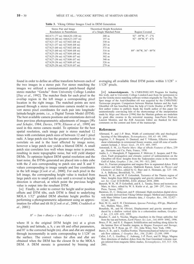
found in order to define an affine transform between each ofthe two images in a stereo pair. For stereo matching theimages we utilized a semiautomated patch-based digitalstereo matcher ‘‘Gotcha’’ from University College London[Day et al., 1992]. The matcher finds for each pixel in theoverlap region in the left image a corresponding pixellocation in the right image. The matched points are nextpassed through a stereo intersection camera model to con-vert stereo pixel coordinates for each pair into longitude/latitude/height points, i.e., a Digital Terrain Model (DTM).The best available camera positions and orientations derivedfrom previous photogrammetric adjustments of images [Wuand Schafer, 1984; Davies, 1978; Eliason et al., 1999] areused in this stereo camera model. To optimize for the bestspatial resolution, each image pair is stereo matched 12times with correlation patch sizes of between 12 and 1 pixelradii. A large patch size has the greatest number of pixels tocorrelate on and is the least affected by image noise,however a large patch size yields a blurred DEM. A smallpatch size correlates less well when image noise is present,resulting in more topographic noise, but will yield sharperDEMs. To optimize highest DEM spatial resolution and theleast noise, the DTMs generated are placed into a data cubewith the Z axis corresponding to patch size and X and Yvalues corresponding to image sample and line coordinatesin the left image [Cook et al., 2000]. For each pixel in theleft image, the corresponding height value is tracked fromlarge patch size to small patch size until a reversal in heightdirection is observed, at which point the previous heightvalue is output into the resultant DTM.[88] Finally, in order to correct for height and/or position
offsets and DTM tilts, each DTM is fitted to underlyingMOLA 1/32� gridded DEM absolute height profiles byperforming a photogrammetric adjustment using an approx-imation for offset and tilt fit [Cook et al., 2000; Craddock etal., 2001]:
H 0 ¼ lonþ dlonð Þaþ latþ dlatð Þbþ cþ H ðA2Þ
where H is the original DTM height (m) at a givenlongitude and latitude, a, b, c are tilt and offset parameters,and H’ is the corrected height (m). dlon and dlat are steppedthrough incrementally in units corresponding to 1/128� onthe surface. The correct values for dlon and dlat areobtained when the DEM has the closest fit to the MOLADEM. A DEM mosaic is generated by binning and
averaging all available fitted DTM points within 1/128� 1/128� pixels.
[89] Acknowledgments. To CNRS/INSU/ATI Program for fundingthis work, and to University College London/Laser-Scan for permission touse the Gotcha stereo matching software written originally by Tim Day. TheSpot image of the Asal-Ghoubbet rift was acquired by the CNRS/INSUTectoscope program. Comparison between Martian features and the Asal-Ghoubbet rift has benefited from the help of Cecile Doubre at IPGP. Thefirst author wishes to publicly thank the fourth author of this paper forunintentionally convincing him of the shortcomings of the interpretationmade by Mege and Masson [1996] that the Martian grabens are underlainby giant dike swarms in the terrestrial meaning. Jean-Pierre Peulvast,Laurent Montesi, and the JGR Associate Editor are thanked for theircomments on the content and form of the manuscript.
ReferencesAllemand, P., and J.-P. Brun, Width of continental rifts and rheologicallayering of the lithosphere, Tectonophysics, 188, 63–69, 1991.
Angelier, J., F. Bergerat, O. Dauteuil, and T. Villemin, Effective tension-shear relationships in extensional fissure swarms, axial rift zone of north-eastern Iceland, J. Struct. Geol., 19, 673–685, 1997.
Antoniadi, E. M., La Planete Mars: Map of Albedo Features of Mars, 239pp., Hermann and Cie, Paris, France, 1930.
Audin, L., I. Manighetti, P. Tapponnier, F. Metivier, E. Jacques, and P. Hu-chon, Fault propagation and climatic control of sedimentation on theGhoubbet rift floor: Insights from the Tadjouraden cruise in the westernGulf of Aden, Geophys. J. Int., 144, 391–413, 2001.
Baer, G., Fracture propagation and magma flow in segmented dykes: Fieldevidence and fabric analyses, Makhtesh Ramon, Israel, in Physics andChemistry of Dykes, edited by G. Baer and A. Heimann, pp. 125–140,A. A. Balkema, Brookfield, Vt., 1995.
Banerdt, W. B., and M. P. Golombek, Tectonics of the Tharsis region ofMars: Insights from MGS topography and gravity (abstract), Lunar Pla-net. Sci. Conf. [CD-ROM], XXXI, abstract 2038, 2000.
Banerdt, W. B., M. P. Golombek, and K. L. Tanaka, Stress and tectonics onMars, in Mars, edited by W. S. Kiefer et al., pp. 249–297, Univ. Ariz.Press, Tucson, 1992.
Baratoux, D., C. Delacourt, and P. Allemand, High-resolution digital eleva-tion models derived from Viking Orbiter images: Method and comparisonwith Mars Orbiter Laser altimetry data, J. Geophys. Res., 106, 32,927–32,941, 2001.
Best, M. G., and E. H. Christiansen, Igneous Petrology, 458 pp., BlackwellSci., Malden, Mass., 2001.
Bonafede, M., and M. Olivieri, Displacement and gravity anomaly pro-duced by a shallow vertical dyke in a cohesionless medium, Geophys.J. Int., 123, 639–652, 1995.
Boudier, F., and A. Nicolas, Magma chambers in the Oman ophiolite; fedfrom the top and bottom, Earth Planet. Sci. Lett., 144, 6959–6982, 1996.
Bruce, P. M., and H. E. Huppert, Solidification and melting along dykes bythe laminar flow of basaltic magma, in Magma Transport and Storage,edited by M. P. Ryan, pp. 87–101, John Wiley, New York, 1990.
Burov, E. B., and L. Guillou-Frottier, Thermomechanical behavior of largeash flow calderas, J. Geophys. Res., 104, 23,081–23,109, 1999.
Callot, J.-P., L. Geoffroy, C. Aubourg, J.-P. Pozzi, and D. Mege, Magmaflow directions of shallow dykes from the East Greenland volcanic mar-gin inferred from magnetic fabric studies, Tectonophysics, 335, 313–329,2001.
Table 3. Viking Orbiter Images Used in DEM Generation
Stereo Pair and ImageResolution in Parentheses
Theoretical Height Resolutionof a Single Matched Point Region Covered
062A71 (77 m): 044A28 (108 m) 200 m 92�–89�W, 5�–2�S064A10 (80 m): 044A23 (107 m) 197 m 92�–89�W, 9�–6�S627A21 (57 m): 627A02 (68 m) 330 m627A21 (57 m): 627A04 (68 m) 283 m627A23 (60 m): 627A02 (68 m) 375 m627A23 (60 m): 627A04 (68 m) 316 m 89�–84�W, 36�–89�N627A25 (56 m): 627A04 (68 m) 358 m627A25 (56 m): 627A06 (67 m) 302 m627A27 (56 m): 627A06 (67 m) 340 m627A29 (56 m): 627A08 (67 m) 326 m627A29 (56 m): 627A10 (67 m) 279 m
10 - 30 MEGE ET AL.: VOLCANIC RIFTING AT MARTIAN GRABENS

Carr, M. H., and R. Greeley, Volcanic features of Hawaii, a basis forcomparison with Mars, NASA Spec. Publ., SP-403, 211 pp., 1980.
Cattermole, P., Linear volcanic features at Alba Patera, Mars—Probablespatter ridges, J. Geophys. Res., 91, 159–165, 1986.
Cattermole, P., The Story of the Red Planet, 224 pp., Chapman and Hall,New York, 1992.
Cayol, V., J. H. Dieterich, A. T. Okamura, and A. Miklius, High rates offlank deformation prior to the 1983 eruption of Kilauea, Hawaii, Science,288, 2343–2346, 2000.
Chadwick, W. W., Jr., and R. W. Embley, Graben formation associated withrecent dike intrusions and volcanic eruptions on the mid-ocean ridge,J. Geophys. Res., 103, 9807–9825, 1998.
Chen, Y., and W. J. Morgan, A non linear rheology model for mid-oceanridge axis topography, J. Geophys. Res., 95, 17,583–17,604, 1990.
Cook, A. C., T. Day, J.-P. Muller, J. C. Iliffe, D. A. Rothery, G. D. Thorn-hill, and J. B. Murray, A Prolog-based Mars information system, Inter-national Archives of Photogrammetry, Remote Sensing and SpatialInformation Sciences, vol. 17, pp. 788–794, RICS Books, Coventry,U. K., 1992.
Cook, A. C., D. Mege, and R. A. Craddock, Stereo derived digital elevationmodels of Mars fitted to MOLA profiles, Lunar Planet. Sci. Conf. [CD-ROM], XXXI, abstract 2008, 2000.
Craddock, R. A., G. A. Franz, A. C. Cook, and A. D. Howard, High resolu-tion morphometric studies of Martian valley networks in the Iapygia re-gion, Lunar Planet. Sci. Conf. [CD-ROM], XXXII, abstract 1833, 2001.
Dauteuil, O., J. Angelier, F. Bergerat, S. Verrier, and T. Villemin, Defor-mation partitioning inside a fissure swarm of the northern Icelandic rift,J. Struct. Geol., 23, 1359–1372, 2001.
Davies, M. E., F. Y. Katayama, and J. A. Roth, Control net of Mars, NASARep., R-2309, 91 pp., 1978.
Davis, P. A., K. L. Tanaka, and M. P. Golombek, Topography of closeddepressions, scarps, and graben in the North Tharsis region of Mars:Implications for shallow crustal discontinuities and graben formation,Icarus, 114, 403–422, 1995.
Day, T., T, A. C. Cook, and J.-P. Muller, Automated digital topographicmapping techniques for Mars, International Archives of Photogrammetry,Remote Sensing and Spatial Information Sciences, vol. 17, pp. 801–808,RICS Books, Coventry, U. K., 1992.
Delaney, P. T., Rapid intrusion of magma into wet rock: Groundwater flowdue to pore pressure increases, J. Geophys. Res., 87, 7739–7756, 1982.
Delaney, P. T., D. D. Pollard, J. I. Ziony, and E. H. McKee, Field relationsbetween dikes and joints: Emplacement processes and paleostress analy-sis, J. Geophys. Res., 91, 4920–4938, 1986.
Dilek, Y., M. E. Moores, and H. Furnes, Structure of modern oceanic crustand ophiolites and implications for faulting and magmatism at oceanicspreading centers, in Faulting and Magmatism at Mid-Ocean Ridges,Geophys. Monogr. Ser., vol. 106, edited by W. R. Buck et al., pp.219–265, AGU, Washington, D. C., 1998.
Doubre, C., L. Dorbath, I. Manighetti, E. Jacques, and L. Geoffroy, Currentmagmato-tectonic activity in the Asal-Ghoubbet Rift (Afar depression),Republic of Djibouti, Eos Trans. AGU, 82, Fall Meeting Suppl., T51B-0869, 2001.
Durand, C., P. Gente, and O. Dauteuil, Caracteristiques morphologiques dessegments axiaux le long de la dorsale medio-atlantique, C. R. Acad. Sci.,Part II, 320, 411–418, 1995.
Eberle, M. A., and D. W. Forsyth, An alternative, dynamic model of theaxial topographic high at fast spreading ridges, J. Geophys. Res., 103,12,309–12,320, 1998.
Ebinger, C. J., and N. H. Sleep, Cenozoic magmatism throughout East Africaresulting from impact of a single plume, Nature, 395, 788–791, 1998.
Eliason, E., P. A. Garcia, A. Bennett, and C. E. Isbell, Mars MosaickedDigital Image Model (MDIM) and Digital Terrain Model (DTM) [CD-ROM], vol. 15, U.S. Geol. Surv., Flagstaff, Ariz., 1999.
Elsworth, D., and B. Voight, Evaluation of volcano flank instability trig-gered by dyke intrusion, in Volcano Instability on the Earth and OtherPlanets, edited by W. J. McGuire, A. P. Jones, and J. Neuberg, Geol. Soc.Spec. Publ., 110, 45–53, 1996.
Ernst, R. E., and W. R. A. Baragar, Evidence from magnetic fabric for theflow pattern in the Mackenzie giant radiating dyke swarm, Nature, 356,511–513, 1992.
Ernst, R. E., K. L. Buchan, and H. C. Palmer, Giant dyke swarms: Char-acteristics, distribution and geotectonic applications, in Physics andChemistry of Dykes, edited by G. Baer and A. Heimann, pp. 3–21, A.A. Balkema, Brookfield, Vt., 1995.
Ernst, R. E., K. L. Buchan, and H. C. Palmer, Diabase (dolerite) dykeswarms of the world, scale 1:35,000,000, Open File Geol. Surv. Can.,3241, 104 pp., 1996.
Ernst, R. E., E. B. Grosfils, and D. Mege, Giant mafic dyke swarms onEarth, Venus and Mars, Annu. Rev. Earth Planet. Sci., 29, 489–534,2001.
Fialko, Y. A., and A. M. Rubin, Thermal and mechanical aspects of magmaemplacement in giant dike swarms, J. Geophys. Res., 104, 23,033–23,049, 1999.
Forslund, T., and A. Gudmundsson, Crustal spreading due to dikes andfaults in southwest Iceland, J. Struct. Geol., 13, 443–457, 1991.
Garcia, M. O., and M. G. Davis, Submarine growth and internal structure ofocean island volcanoes based on submarine observatiobs of Mauna Loavolcano, Hawaii, Geology, 29, 163–166, 2001.
Garel, E., Modeles analogiques de l’evolution volcano-tectonique de l’axede la dorsale ultra-rapide du Pacifique, DEA thesis, 79 pp., Univ. e deBretagne Occidentale, Brest, France, 1998.
Garel, E., O. Dauteuil, and Y. Lagabrielle, Deformation processes at fast toultra-fast oceanic spreading axes: Mechanical approach, Tectonophysics,346, 223–246, 2002.
Goff, J. A., A global and regional analysis of near ridge abyssal hill mor-phology, J. Geophys. Res., 96, 21,713–21,737, 1991.
Golombek, M. P., Structural analysis of lunar graben and the shallow crustalstructure of the Moon, J. Geophys. Res., 84, 4657–4666, 1979.
Golombek, M. P., K. L. Tanaka, D. J. Chadwick, B. J. Franklin, and P. A.Davis, Extension across Tempe Terra and Sirenum provinces on Marsfrom measurements of fault scarp widths, Lunar Planet. Sci. Conf., XXV,443–444, 1994.
Greeley, R., Basaltic ‘‘plains’’ volcanism, in Volcanism of the EasternSnake River Plain, Idaho: A Comparative Planetary Geology Guidebook,edited by R. Greeley and J. S. King, NASA Contract. Rep., CR-154621,23–44, 1977a.
Greeley, R., Aerial guide to the geology of the central and eastern SnakeRiver Plain, in Volcanism of the Eastern Snake River Plain, Idaho: AComparative Planetary Geology Guidebook, edited by R. Greeley andJ. S. King, NASA Contract. Rep., CR-154621, 59–111, 1977b.
Greeley, R., and R. M. Batson, Planetary Mapping, 196 pp., CambridgeUniv., New York, 1990.
Greeley, R., and J. E. Guest, Geologic map of the eastern equatorial regionof Mars, scale 1:15,000,000, U.S.Geol. Surv. Misc. Invest. Ser., I-1802-B,1987.
Greeley, R., and P. H. Schultz, Possible planetary analogs to Snake Riverplain basalt features, in Volcanism of the Eastern Snake River Plain,Idaho: A Comparative Planetary Geology Guidebook, edited by R. Gree-ley and J. S. King, NASA Contract. Rep., CR-154621, 233–251, 1977.
Greeley, R., E. Theilig, and J. S. King, Guide to the geology of King’s Bowllava field, in Volcanism of the Eastern Snake River Plain, Idaho: AComparative Planetary Geology Guidebook, edited by R. Greeley andJ. S. King, NASA Contract. Rep., CR-154621, 171–188, 1977.
Grosfils, E., and J. W. Head, The global distribution of giant radiating dikeswarms on Venus: Implications for the global stress state, Geophys. Res.Lett., 21, 701–704, 1994a.
Grosfils, E., and J. W. Head, Emplacement of a radiating dike swarm inwestern Vinmara Planitia, Venus: Interpretation of the regional stress fieldorientation and subsurface magmatic configuration, Earth Moon Planets,66, 153–171, 1994b.
Gudmundsson, A., Tectonic aspects of dykes in northwestern Iceland, Jo-kull, 34, 81–96, 1984.
Gudmundsson, A., Dyke emplacement at divergent plate boundaries, inMafic Dykes and Emplacement Mechanisms, edited by A. J. Parker,P. C. Rickwood, and D. H. Tucker, pp. 47–62, A. A. Balkema, Brook-field, Vt., 1990a.
Gudmundsson, A., Emplacement of dikes, sills and crustal magma cham-bers at divergent plate boundaries, Tectonophysics, 176, 257 –275,1990b.
Gudmundsson, A., Formation and growth of normal faults at the divergentplate boundary in Iceland, Terra Nova, 4, 464–471, 1992.
Gudmundsson, A., The geometry and growth of dykes, in Physics andChemistry of Dykes, edited by G. Baer and A. Heimann, A. A. Balkema,pp. 23–34, Brookfield, Vt., 1995a.
Gudmundsson, A., Infrastructure and mechanics of volcanic systems inIceland, J. Volcanol. Geotherm. Res., 64, 1–22, 1995b.
Head, J. W., III, and L. Wilson, Magma reservoirs and neutral buoyancyzones on Venus: Implications for the formation and evolution of volcaniclandforms, J. Geophys. Res., 97, 3877–3903, 1992.
Head, J. W., III, and L. Wilson, Lunar graben formation due to near-surfacedeformation accompanying dike emplacement, Planet. Space Sci., 41,719–727, 1994.
Hey, R. N., J. M. Sinton, and F. K. Duennebier, Propagating rifts andspreading centers, The Geology of North America, vol. N, The EasternPacific Ocean and Hawaii, edited by E. L. Winterer, D. M. Hussong, andR. W. Decker, pp. 161–176, Geol. Soc. of Am., Boulder, Colo., 1989.
Hoek, J. D., Mafic dykes of the Vestfold Hills, East Antarctica. An analysisof the emplacement mechanism of tholeiitic dyke swarms and of the roleof dyke emplacement during crustal extension, Ph.D. thesis, 133 pp.,Univ. of Utrecht, Utrecht, Neth., 1994.
MEGE ET AL.: VOLCANIC RIFTING AT MARTIAN GRABENS 10 - 31

Hoek, J. D., Dyke propagation and arrest in Proterozoic tholeiitic dykeswarms, Vestfold Hills, East Antarctica, in Physics and Chemistry ofDykes, edited by G. Baer and A. Heimann, pp. 79–93, A. A. Balkema,Brookfield, Vt., 1995.
Hubbert, M. K., Theory of scale models as applied to the study of geologicstructures, Geol. Soc. Am. Bull., 48, 1459–1520, 1937.
Kappel, E. S., and W. B. F. Ryan, Volcanic episodicity and a non-steadystate rift valley along the northeast Pacific spreading center: Evidencefrom SeaMARC I, J. Geophys. Res., 91, 13,925–13,940, 1986.
Karlo, J., Basaltic ‘‘plains’’ volcanism, in Volcanism of the Eastern SnakeRiver Plain, Idaho: A Comparative Planetary Geology Guidebook, editedby R. Greeley and J. S. King, NASA Contract. Rep., CR-154621, 121–131, 1977.
Kiefer, W. S., Magma production and mantle convection on Mars, LunarPlanet. Sci. Conf. [CD-ROM], XXXI, abstract 1527, 2000.
Koenig, E., and D. D. Pollard, Mapping and modeling of radial fracturepatterns, J. Geophys. Res., 103, 15,183–15,202, 1998.
Kumarapeli, S. P., K. St. Seymour, A. Fowler, and H. Pintson, The problemof the magma source of a giant radiating mafic dyke swarm in a failedarm setting, in Mafic Dykes and Emplacement Mechanisms, edited byA. J. Parker, P. C. Rickwood, and D. H. Tucker, pp. 163–171, A. A.Balkema, Brookfield, Vt., 1990.
Kusznir, N. J., and M. H. P. Bott, Stress concentration in the upper litho-sphere caused by underlying viscoelastic creep, Tectonophysics, 43,247–256, 1977.
Lagabrielle, Y., and M.-H. Cormier, Formation of large summit troughsalong the East Pacific Rise as collapse calderas: An evolutionary model,J. Geophys. Res., 104, 12,971–12,988, 1999.
Lagabrielle, Y., E. Garel, O. Dauteuil, and M.-H. Cormier, Extensionalfaulting and caldera collapse in the axial region of fast spreading ridges:Analog modeling, J. Geophys. Res., 106, 2005–2016, 2001.
Le Dain, Y., B. Robineau, and P. Tapponnier, Les effets tectoniques del’evenement sismique et volcanique de novembre 1978 dans le riftd’Asal-Ghoubbet, Bull. Soc. Geol. Fr., 22, 817–822, 1979.
Lister, J. R., and R. C. Kerr, Fluid-mechanical models of crack propagationand their application to magma transport in dykes, J. Geophys. Res., 96,10,049–10,077, 1991.
Liu, S. Y., and L. Wilson, Collapse pits due to gas release from shallowdikes on Mars, Lunar Planet. Sci. Conf. [CD-ROM], XXXI, abstract 1602,1998.
Lonsdale, P., Structural geomorphology of a fast-spreading rise crest: TheEast Pacific Rise near 3�250S, Mar. Geophys. Res., 3, 251–293, 1977.
Macdonald, K. C., and P. J. Fox, The axial summit graben and cross-sec-tional shape of the East-Pacific Rise as indicators of axial magma cham-bers and recent volcanic eruptions, Earth Planet. Sci. Lett., 88, 119–131,1988.
Manighetti, I., P. Tapponnier, P.-Y. Gillot, E. Jacques, V. Courtillot, O. Ar-mijo, J.-C. Ruegg, and G. King, Propagation of rifting along the Arabia-Somalia plate boundary: Into Afar, J. Geophys. Res., 103, 4947–4974,1998.
Mastin, L. G., and D. D. Pollard, Surface deformation and shallow dikeintrusion processes at Inyo craters, Long Valley, California, J. Geophys.Res., 93, 13,221–13,235, 1988.
McEwen, A. S., M. C. Malin, M. H. Carr, and W. K. Hartmann, Volumi-nous volcanism on early Mars revealed in Valles Marineris, Nature, 397,584–586, 1999.
McGetchin, T. R., and G. W. Ullrich, Xenoliths and diatremes with infer-ences for the Moon, Mars, and Venus, J. Geophys. Res., 78, 1833–1853,1973.
McGill, G. E., and A. W. Stromquist, The graben in Canyonlands NationalPark, Utah: Geometry, mechanics, and kinematics, J. Geophys. Res., 84,4547–4563, 1979.
McKenzie, D., J. M. McKenzie, and R. S. Saunders, Dike emplacement onVenus and on Earth, J. Geophys. Res., 97, 15,977–15,990, 1992.
Mege, D., Uniformitarian plume tectonics: The post-Archean Earth andMars, in Mantle Plumes: Their Identification Through Time, edited byR. E. Ernst and K. L. Buchan, Geol. Soc. Am. Spec. Pap., 352, 141–164,2001.
Mege, D., and R. E. Ernst, Contractional effects of mantle plumes on Earth,Mars and Venus, in Mantle Plumes: Their Identification Through Time,edited by R. E. Ernst and K. L. Buchan, Geol. Soc. Am. Spec. Pap., 352,103–140, 2001.
Mege, D., and P. Masson, A plume tectonics model for the Tharsis pro-vince, Mars, Planet. Space Sci., 44, 1499–1546, 1996.
Mege, D., and P. Masson, Tension fracturing at Uranius Fossae, Mars,Lunar Planet Sci. Conf., XXVIII, 931–932, 1997.
Mege, D., Y. Lagabrielle, E. Garel, M.-H. Cormier, and A. C. Cook, Col-lapse features and narrow graben on Mars and Venus: Dike emplacementand deflation of underlying magma chamber, Lunar Planet. Sci. Conf.[CD-ROM], XXXI, abstract 1854, 2000.
Melosh, H. J., and C. A. Williams Jr., Mechanics of graben formation incrustal rocks: A finite element analysis, J. Geophys. Res., 94, 13,961–13,973, 1989.
Merle, O., and A. Borgia, Scaled experiments of volcanic spreading, J. Geo-phys. Res., 101, 13,805–13,817, 1996.
MOLA Science Team, paper presented at First Mars Global SurveyorScience Press Conference, Jet. Propul. Lab., Pasadena, Calif., 1997.(Available at mars.jpl.nasa.gov/mgs/sci/mola/data1/mola_first.html)
Montesi, L. G. J., Concentric dike swarms on the flanks of Pavonis Mons:Implications for the evolution of Martian shield volcanoes and mantleplumes, in Mantle Plumes: Their Identification Through Time, edited byR. E. Ernst and K. L. Buchan, Geol. Soc. Am. Spec. Pap., 352, 165–181,2001.
Morgan, J. K., G. F. Moore, D. J. Hills, and S. Leslie, Overthrusting andsediment accretion along Kilauea’s mobile south flank, Hawaii: Evidencefor volcanic spreading from marine seismic reflection data, Geology, 28,667–670, 2000.
Odonne, F., I. Menard, G. J. Massonnat, and J. P. Rolando, Abnormalreverse faulting above a depleting reservoir, Geology, 27, 111–114, 1999.
Okubo, C. H., and S. J. Martel, Pit crater formation on Kilauea volcano,Hawaii, J. Volcanol. Geotherm. Res., 86, 1–18, 1998.
Opheim, J. A., and A. Gudmundsson, Formation and geometry of fractures,and related volcanism, of the Krafla fissure swarm, northeast Iceland,Geol. Soc. Am. Bull., 101, 1608–1622, 1989.
Peulvast, J.-P., D. Mege, J. Chiciak, F. Costard, and P. Masson, Origin anddevelopment of high-energy slopes in Valles Marineris (Mars); relationswith tectonics and volatiles, Geomorphology, 37, 329–352, 2001.
Phillips, R. J., M. T. Zuber, S. C. Solomon, M. P. Golombek, B. M.Jakosky, W. B. Banerdt, D. E. Smith, R. M. E. Williams, B. M. Hynek,O. Aharonson, and S. A. Hauck II, Ancient geodynamics and global-scalehydrology of Mars, Science, 291, 2587–2591, 2001.
Platten, I. M., Incremental dilation of magma filled fractures: Evidencefrom dykes on the Isle of Skye, Scotland, J. Struct. Geol., 22, 1153–1164, 2000.
Plescia, J. B., Graben and extension in northern Tharsis, Mars, J. Geophys.Res., 96, 18,883–18,895, 1991.
Pollard, D. D., and G. Holzhausen, On the mechanical interaction betweena fluid-filled fracture and the Earth’s surface, Tectonophysics, 53, 27–57,1979.
Pollard, D. D., P. T. Delaney, W. A. Duffield, E. T. Endo, and A. T.Okamura, Surface deformation in volcanic rift zones, Tectonophysics,94, 541–584, 1983.
Reidel, S. P., T. L. Tolan, P. R. Hooper, M. H. Beeson, K. R. Fecht, R. D.Bentley, and J. L. Anderson, The Grande Ronde basalt, Columbia RiverBasalt Group; stratigraphic descriptions and correlations in Washington,Oregon, and Idaho, in Volcanism and Tectonism in the Columbia RiverFlood-Basalt Province, edited by S. P. Reidel and P. R. Hooper, Geol.Soc. Am. Spec. Pap. 239, 21–53, 1989.
Roche, O., T. Druitt, and O. Merle, Experimental study of caldera forma-tion, J. Geophys. Res., 105, 395–416, 2000.
Roche, O., B. van Wyk de Vries, and T. H. Druitt, Sub-surface structuresand collapse mechanisms of summit pit craters, J. Volcanol. Geotherm.Res., 105, 1–18, 2001.
Rubin, A. M., Dike-induced faulting and graben subsidence in volcanic riftzones, J. Geophys. Res., 97, 1839–1858, 1992.
Rubin, A. M., Tensile fracture of rock at high confining pressure: Implica-tions for dike propagation, J. Geophys. Res., 98, 15,919–15,935, 1993.
Rubin, A. M., Propagation of magma-filled cracks, Annu. Rev. Earth Pla-net. Sci., 23, 287–336, 1995.
Scheirer, D. S., and K. C. Macdonald, The variation in cross-sectional areaof the axial ridge along the East Pacific Rise: Evidence for the magmaticbudget of a fast-spreading center, J. Geophys. Res., 98, 7871–7885,1993.
Schultz, R. A., Do pit-crater chain grow up to be Valles Marineris canyons?,NASA Tech. Memo., 4130, 539–540, 1988.
Schultz, R. A., Relative scale and the strength and deformability of rockmasses, J. Struct. Geol., 18, 1139–1149, 1996.
Schultz, R. A., Displacement-length scaling for terrestrial and Martianfaults: Implications for Valles Marineris and shallow planetary graben,J. Geophys. Res., 102, 12,009–12,015, 1997.
Schultz, R. A., Multiple-process origin of Valles Marineris basins andtroughs, Mars, Planet. Space Sci., 46, 827–834, 1998.
Schultz, R. A., Fault-population statistics at the Valles Marineris Exten-sional Province, Mars: Implications for segment linkage, crustal strains,and its geodynamical development, Tectonophysics, 316, 169–193,2000.
Schultz, R. A., and A. N. Fori, Fault-length statistics and implications ofgraben sets at Candor Mensa, Mars, J. Struct. Geol., 18, 373–383, 1996.
Schultz, R. A., and J. M. Moore, New observations of grabens from theNeedles district, Canyonlands National Park, in Geology and Resources
10 - 32 MEGE ET AL.: VOLCANIC RIFTING AT MARTIAN GRABENS

of the Paradox Basin: Utah, edited by A. C. Huffman Jr., W. R. Lund,and L. H. Goodwin, Geol. Assoc. Guideb., 25, 295–302, 1996.
Schultz, R. A., J. A. Moore, E. B. Grosfils, K. L. Tanaka, D. Mege,E. Hauber, and P. Kronberg, Revised model for simple planetary grabenand tectonic implications, Lunar Planet. Sci. Conf. [CD-ROM], XXXI,abstract 1175, 2000.
Scott D. H., and K. L. Tanaka , Geologic map of the western equatorialregion of Mars, U.S. Geol. Surv. Misc. Invest. Ser., I-1802-A, 1986.
Scott, E. D., L. Wilson, and J. W. Head III, Martian plinian eruptions andpit chain craters, Lunar Planet. Sci. Conf. [CD-ROM], XXXI, abstract1332, 2000.
Sempere, J. C., and K. C. Macdonald, Overlapping spreading centers: Im-plications from crack growth simulation by the displacement discontinu-ity method, Tectonics, 5, 151–163, 1986.
Shah, A. K., M.-H. Cormier, W. B. F. Ryan, W. Jin, J. Sinton, E. Bergma-nis, J. Carlut, A. Bradley, and D. Yoerger, Episodic dike swarms inferredfrom near-bottom magnetic anomaly maps at the southern East PacificRise, J. Geophys. Res., 108(B2), 2097, doi:10.1029/2001JB000564,2003.
Shaw, W. J., and J. Lin, Models of ocean ridge lithosphere deformation:Dependence on crustal thickness, spreading rate and segmentation, J. Geo-phys. Res., 101, 17,977–17,993, 1996.
Sinton, J., E. Bergmanis, K. Rubin, R. Batiza, T. K. P. Gregg, K. Gronvold,K. C. Macdonald, and S. M. White, Volcanic eruptions on mid-oceanridges: New evidence from the superfast spreading East Pacific Rise,17�–19�S, J. Geophys. Res., 107(B6), doi:10.1029/2000JB000090, 2002.
Sleep, N. H., Martian plate tectonics, J. Geophys. Res., 99, 5639–5655,1994a.
Sleep, N. H., Lithospheric thinning by midplate mantle plumes and thethermal history of hot plume material ponded at sublithospheric depths,J. Geophys. Res., 99, 9327–9343, 1994b.
Smith, D. E., et al., Mars Orbiter Laser Altimeter (MOLA): Experimentsummary after the first year of global mapping of Mars, J. Geophys. Res.,106, 23,689–23,722, 2001.
Snyder, C. W., The missions of the Viking Orbiters, J. Geophys. Res., 82,3971–3983, 1977.
Tanaka, K. L., Tectonic history of the Alba Patera-Ceraunius Fossae regionof Mars, Proc. Lunar Planet. Sci. Conf., 20th, 515–523, 1990.
Tanaka, K. L., and P. A. Davis, Tectonic history of the Syria Planumprovince of Mars, J. Geophys. Res., 93, 14,893–14,917, 1988.
Tanaka, K. L., and M. P. Golombek, Martian tension fractures and theformation of graben and collapse features at Valles Marineris, Proc.Lunar Planet. Sci. Conf., 19th, 383–396, 1989.
Tanaka, K. L., M. P. Golombek, and W. B. Banerdt, Reconciliation of stressand structural histories of the Tharsis region of Mars, J. Geophys. Res.,96, 15,617–15,633, 1991.
Tazieff, H., The Erta’ Ale volcano, Rev. Geogr. Phys. Geol. Dyn., 15, 437–441, 1973.
Thompson, R. N., and S. A. Gibson, Subcontinental mantle plumes, hot-spots and pre-existing thinspots, J. Geol. Soc. London, 148, 973–977,1991.
Turcotte, D. L., On the role of laminar and turbulent flow in buoyancydriven magma fractures, in Magma Transport and Storage, edited byM. P. Ryan, pp. 103–111, John Wiley, New York, 1990.
van Wyk de Vries, B., and O. Merle, The effect of volcanic constructs onrift fault patterns, Geology, 24, 643–646, 1996.
Vendeville, B., P. R. Cobbold, P. H. Davy, J.-P. Brun, and P. Choukroune,Physicals models of extentional tectonics at various scales, in ContinentalExtensional Tectonics, edited by M. P. Coward, M. F. Dewey, and P. L.Hancock, Geol. Soc. London Spec. Publ., 28, 95–107, 1987.
Watters, T. R., Compressional tectonism on Mars, J. Geophys. Res., 98,17,049–17,060, 1993.
Wilkins, S. J., and R. A. Schultz, Structural style and mode of extension inthe northern Tempe rift, Lunar Planet. Sci. Conf. [CD-ROM], XXXII,abstract, 1253, 2001.
Wilson, L., and J. W. Head, Mars: Review and analysis of volcanic eruptiontheory and relationships to observed landforms, Rev. Geophys., 32, 221–263, 1994.
Wilson, L., and J. W. Head III, Tharsis-radial graben systems as the surfacemanifestation of plume-related dike intrusion complexes: Models andimplications, Lunar Planet. Sci. Conf. [CD-ROM], XXXI, abstract1371, 2000.
Wise, D. U., Faulting and stress trajectories near Alba volcano, northernTharsis ridge of Mars, Geol. Romana, 430–433, 1976.
Wu, S. S. C., and F. J. Schafer, Mars control network, Tech. Pap. Am. Soc.Photogramm., 50, 456–463, 1984.
Yoerger, D. R., A. M. Bradley, B. B. Walden, M.-H. Cormier, and W. B. F.Ryan, Fine-scale seafloor survey in rugged deep-ocean terrain with anautonomous robot, paper presented at IEEE International Conference onRobotics Automation, Inst. of Electr. and Electr. Eng., San Francisco,Calif., 2000.
Zuber, M. T., The crust and mantle of Mars, Nature, 412, 220–227, 2001.Zuber, M. T., et al., Internal structure and early thermal evolution of Marsfrom Mars Global Surveyor topography and gravity, Science, 287, 1788–1793, 2000.
�����������������������A. C. Cook, School of Computer Science and Information Technology,
University of Nottingham, Jubilee Campus, Wollaton Road, Nottingham,NG8 1BB, UK. ([email protected])M.-H. Cormier, Lamont-Doherty Earth Observatory, Columbia Univer-
sity, Palisades, NY 10964, USA. ([email protected])E. Garel, Laboratoire de Geodynamique des Rifts et des Marges Passives,
Universite du Maine, Avenue Olivier Messiaen, 72085 Le Mans Cedex 9,France. ([email protected])Y. Lagabrielle, Institut de Recherche pour le Developpement, CNRS
UMR 6538, Universite de Bretagne Occidentale, Place Nicolas Copernic,29280 Plouzane, France. ([email protected])D. Mege, Laboratoire de Tectonique, CNRS UMR 7072, boıte 129,
Universite Pierre et Marie Curie, 4 Place Jussieu, 75252 Paris cedex 05,France. ([email protected])
MEGE ET AL.: VOLCANIC RIFTING AT MARTIAN GRABENS 10 - 33