Embed Size (px)
Citation preview
UNESCO – EOLS
S
SAMPLE C
HAPTERS
PHYSICAL METHODS, INSTRUMENTS AND MEASUREMENTS - Vol. III Permanent Magnets - T. R. Ní Mhíocháin and J. M. D. Coey
©Encyclopedia Of Life Support Systems (EOLSS)
PERMANENT MAGNETS T. R. Ní Mhíocháin and J. M. D. Coey Physics Department, Trinity College, Dublin 2, Ireland. Keywords: Consumer electronics, electromagnetism, micromachines, computers, data storage, thin films, multilayers, renewable and sustainable technology, hysteresis, energy product, anisotropy, Alnicos, ferrites, rare-earth permanent magnets, processing techniques, magnet structures, Halbach cylinder, actuators, motors, generators, couplings and bearings, sensors, magnetic separation, magnetic levitation, magnetic resonance imaging, electric vehicles. Contents 1. Introduction 2. Magnetic Properties 2.1 Hysteresis 2.2 Domains 2.3 Flux Density and Energy Product 2.4 Magnetic Order 2.5 Anisotropy 2.6 Micromagnetism 2.7 Domain walls 2.8 Units 3. Magnet Materials 3.1 Bulk materials 3.2 Thin Films and Multilayers 4. Magnet Processing 4.1 Bulk Materials 4.2 Thin Films 5. Magnet Structures 5.1 Materials Considerations 5.2 Uniform Fields 5.3 Non-Uniform Fields 5.4 Time-Varying Fields 5.5 Magnetic ‘Images’ 6. Magnet Applications 6.1 Electrical Machines 6.2 Magnetic Resonance Imaging (MRI) 6.3 Industrial Materials Processing 6.4 Magnetic Separation 6.5 Couplings and Bearings 6.6 Magnetic Clamps 6.7 Particle Beam Control 6.8 Sensors 6.9 Magnetic Memory 6.10 Miscellaneous 7. Prospects Glossary

UNESCO – EOLS
S
SAMPLE C
HAPTERS
PHYSICAL METHODS, INSTRUMENTS AND MEASUREMENTS - Vol. III Permanent Magnets - T. R. Ní Mhíocháin and J. M. D. Coey
©Encyclopedia Of Life Support Systems (EOLSS)
Bibliography Biographical Sketches Summary Permanent magnets are ubiquitous. They turn up everywhere in our daily lives — in computers, audiovisual equipment, telephones, automobiles, kitchen appliances, microwave ovens, garbage separators and medical imaging devices. This article offers an overview of all aspects of permanent magnetism from theory to applications. It begins by placing the current state of the field within its venerable historical context, and showing how the quality of permanent magnets improved exponentially during the 20th century. The basic theoretical concepts and the principles on which they are based are then explained in an accessible fashion. Those materials possessing attractive properties for use as magnets are classified into a few families, each of which is presented in terms of its magnetic and crystallographic properties. The various steps involved in the processing of both ferrite and rare-earth magnets from raw materials are also outlined. Finally, the ever-expanding applications of permanent magnets are discussed in terms of the nature of the magnetic field they produce and the physical effects involved. Permanent magnets are assembled into structures that can generate magnetic fields of up to about two teslas, which are uniform, non-uniform or time-varying according to the requirements. Since the magnetic fields are produced by compact and convenient magnet structures which require no continual expenditure of energy, permanent magnets are ideally suited to renewable and sustainable technologies such as autonomous energy conversion. 1. Introduction Permanent magnets have been known since antiquity. Lodestones, rare rocks composed mainly of iron oxide, which have been naturally magnetized by lightning strikes, offered humans their first palpable demonstration of action at a distance, providing a stable magnetic field which could be manipulated by the owner of the magnetic stone. The counterintuitive attraction of iron to the magnet delights children, and archetypical but quite obsolete images of bright red horseshoe magnets continue to adorn science texts for primary schools. Modern permanent magnets are highly-sophisticated products of a union between physics and metallurgy. Some rare-earth elements can be alloyed with iron or cobalt to produce materials with outstanding magnetic properties. Neodymium-iron-boron magnets, for example, are roughly one hundred times as efficient as the steel bar and horseshoe magnets available at the beginning of the 20th century. Many consumer electronic devices - portable computers and telephones, personal stereos, cordless tools - would not exist without rare earth magnets, which date from the late 1960s. Cheaper ceramic ferrite magnets are very widely used for holding applications and small dc motors. Global production of permanent magnets averages to more than 100 g per annum for each person on Earth. Magnets are ubiquitous. There may be as many as 70 in a modern car (Figure 1). Computer data is stored in billions of minute semi-permanent magnets representing the bits on a hard disc.

UNESCO – EOLS
S
SAMPLE C
HAPTERS
PHYSICAL METHODS, INSTRUMENTS AND MEASUREMENTS - Vol. III Permanent Magnets - T. R. Ní Mhíocháin and J. M. D. Coey
©Encyclopedia Of Life Support Systems (EOLSS)
Figure 1: Some modern cars have as many as 70 magnets built into them Magnetism has gripped the imagination of researchers and inventors from ancient times as a possible answer to the dream of perpetual motion. The first European magnetism text, ‘Epistola de Magnete’ by Petrus Peregrinus, published in 1269, shows an illustration of a perpetuum mobile based on attracting and repelling magnets. Delicate escarpment mechanisms were designed in the 18th century to turn for ever near the magnetic equator. Patents were being issued by the US patent office for magnetic perpetual motion machines as late as the 1970s. Yet the dream of achieving perpetual motion has never become a reality. Increasingly astute analysis of the reasons for this failure contributed to the formulation of one of the defining principles of physics— the Law of Conservation of Energy. Myths concerning the origins of magnetism can be found on four continents, in ancient Greece, Egypt, China and Guatemala, but it was in China in the centuries preceding our era that a protoscience of magnetism developed in the context of arcane practices of geomancy and divination. Shen Kua described the suspended compass in 1088. By the end of the Sung period (960-1279), technology for manufacturing steel wire for use as compass needles and magnetizing them with a lodestone or by cooling in the Earth's magnetic field was firmly established, both in China and in Europe. Adoption of the mariner's compass, the first practical permanent magnet device, led to the great voyages of discovery which changed the face of the globe. Modern understanding of magnetism began with the discovery by Oersted in 1820 of its relationship with electricity; electric current flowing in a loop generates a magnetic field in the surrounding space. This eventually led to the classical unification of electricity, magnetism and light in Maxwell's equations. But only in the 20th century was a satisfactory fundamental understanding of the phenomenon attained, which rests on the
UNESCO – EOLS
S
SAMPLE C
HAPTERS
PHYSICAL METHODS, INSTRUMENTS AND MEASUREMENTS - Vol. III Permanent Magnets - T. R. Ní Mhíocháin and J. M. D. Coey
©Encyclopedia Of Life Support Systems (EOLSS)
two great achievements of modern physics, relativity and quantum mechanics. Permanent magnets generate a magnetic field with no need for any external power source, thanks to the perpetual quantized electric currents associated with spin and orbital motions of the electronic charges. All magnetism is related to the angular momentum associated with electric currents; there are no elementary magnetic poles. The elementary quantity is the magnetic dipole m , equivalent to a current loop; the magnetic dipole moment associated with an orbiting electron is quantized in units of Bohr magnetons, -24 2
B1µ = 9.274 10 Am× . The magnetization M of a solid is just the sum of all the atomic magnetic moments associated with each atom's electrons, sum per unit volume. Units of M are amperes per meter (A m-1). Until the end of the 19th century, the only artificial magnets were weak and unstable, made of hard carbon steel. For a while following Oersted's discovery, steel magnets featured prominently in early manifestations of electrotechnology. Motors were built incorporating batteries of horseshoe magnets; generators were engineered around its elegant but bulky form. However, these early permanent magnets were soon replaced by the more compact and versatile electromagnets, resulting from the demonstration by Ampère and Arago that a current-carrying coil is equivalent to a magnet. This work, together with Faraday's principle of electromagnetic induction, led to the electrification of our planet. However, with the recent dramatic improvement in their magnetic properties (Figure 2), permanent magnets are in turn replacing electromagnets in many small electrical machines, and as a means of generating magnetic fields. Ferromagnetic properties are most simply characterized by the energy product, a figure of merit proportional to the energy in kilojoules per cubic meter (kJm-3) stored in the magnetic field created by a given volume of magnetic material. Energy product increased exponentially during the 20th century, doubling roughly every twelve years (Figure 2). The improvement of energy product was due to the introduction of new families of magnetic materials. Discovery of cobalt magnet steels in Japan in the early part of the 20th century led to the development of a family of iron-aluminum-nickel-cobalt alloys - the Alnicos - some of which are still in use today, especially in applications where the magnet must withstand high temperatures up to 500 °C. Ferromagnetism in any given material breaks down above a temperature CT known as its Curie point. The maximum practical operating temperature of a permanent magnet is well below CT . Cobalt-based alloys tend to have higher Curie points than iron-based alloys, and the elevated Curie points of Alnicos ( CT ~ 880 °C) allow high operating temperatures.

UNESCO – EOLS
S
SAMPLE C
HAPTERS
PHYSICAL METHODS, INSTRUMENTS AND MEASUREMENTS - Vol. III Permanent Magnets - T. R. Ní Mhíocháin and J. M. D. Coey
©Encyclopedia Of Life Support Systems (EOLSS)
Figure 2: Progress of the energy product max( )BH of permanent magnets during the 20th century.
A major advance came in the early 1950s with the development in the Netherlands of synthetic hexagonal ferrites. Like lodestone, these magnets are composed of an iron oxide ( 12 19 12 19BaFe O or SrFe O ). Although they have never held the record energy product, they are cheap, effective and reliable. Ferrites today account for 90% of the mass and over half the value of all magnets produced worldwide, an annual market worth roughly six billion US$ in 2005, which is growing at more than 10% each year. The other half of the market is mostly accounted for by rare-earth magnets having energy products ten times greater than ferrites. Despite their name, light 'rare-earths' are fairly abundant in the Earth’s curst like cobalt, lead or zinc. Cobalt is a strategic metal, subject to large fluctuations in supply and price. Iron is 5 % of the Earth's crust by weight, several thousand times as abundant as cobalt. Neodymium is one of the rare-earth elements which can be alloyed with iron or cobalt to produce materials with excellent magnetic properties. The laboratory record for energy product is 450 kJm-3, held by a neodymium-iron-boron alloy. The most common composition involves the
2 14Nd Fe Bphase, and accounts for almost a third of the total permanent magnet market. The applications pie chart in Figure 3 shows the market for permanent magnets and the breakdown among the main magnet types. Rare earth magnets are compact, top-of-the-range magnetic flux sources. Table 1 lists characteristics of typical commercial magnets.

UNESCO – EOLS
S
SAMPLE C
HAPTERS
PHYSICAL METHODS, INSTRUMENTS AND MEASUREMENTS - Vol. III Permanent Magnets - T. R. Ní Mhíocháin and J. M. D. Coey
©Encyclopedia Of Life Support Systems (EOLSS)
Figure 3: Estimate of the world market for applications of permanent magnets.
r
(T)B
s (T)J
c (kA/m)H
c
(kA/m)
HB max3
( )
(kJ/ m )
BH
12 19SrFe O 0.41 0.47 275 265 34 Alnico 1.25 1.40 54 52 43
5SmCo 0.88 0.95 1700 660 150 2 17Sm Co * 1.08 1.15 800 800 220 2 14Nd Fe B 1.28 1.54 1000 900 300
*intergrown with 1:5 phase
Table 1: Characteristics of typical commercial oriented magnets
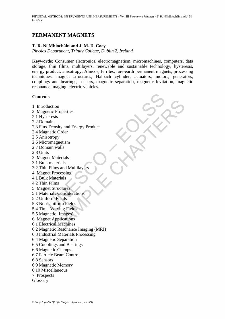
The magnetic field delivered to the airgap around the magnet may be homogeneous or inhomogeneous, steady or time varying. Permanent magnet applications can be classified in several ways. One scheme uses the physical effect that is being exploited — torque on a magnet in an external field, force on a magnet or on a piece of soft magnetic material in a nonuniform field, force on a current-carrying conductor or on charged particles moving in a magnetic field, induced emf, Zeeman splitting of energy levels etc. A simpler scheme focuses on the characteristics of the magnet, distinguishing between static applications where the magnet exists to produce a magnetic field in some region of space, and dynamic applications where the field within the magnet itself varies during operation. A list of typical examples of magnet applications is given in Table 2.
Field Magnetic effect Type Examples
UNESCO – EOLS
S
SAMPLE C
HAPTERS
PHYSICAL METHODS, INSTRUMENTS AND MEASUREMENTS - Vol. III Permanent Magnets - T. R. Ní Mhíocháin and J. M. D. Coey
©Encyclopedia Of Life Support Systems (EOLSS)
Homogeneous Zeeman splitting static magnetic resonance imaging torque static alignment of magnetic powder Hall effect,
magnetoresistance static sensors, read-heads
force on conductor dynamic motors, actuators, loudspeakers induced emf dynamic generators, microphones Inhomogeneous force on charged
particles static beam control, radiation sources
(microwave, uv, X-ray) force on magnet dynamic bearings, couplings, Maglev force on paramagnet dynamic mineral separation Time-varying varying field dynamic magnetometers force on iron dynamic switchable clamps, holding
magnets eddy currents dynamic metal separation, brakes
Table 2: Summary of permanent magnet applications
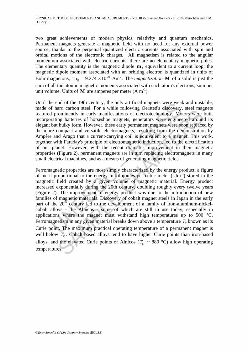
As the energy product increases, there is a trend towards moving-magnet designs coupled with miniaturization. Permanent magnet devices become smaller and lighter as the permanent magnets required to deliver a given amount of energy become smaller, as illustrated in Figure 4. The advantage of the permanent magnet can be savored by comparing a small disk-shaped magnet with a coil having the same magnetic moment. A disk of diameter 8 mm and height 2 mm made of a material with -1 = 1 MAmM has
2 ~ 0.1 Amm . An equivalent coil of the same diameter would need 2000 Ampere-turns, and energy would be continually dissipated in the coil in order to maintain the field.
Figure 4: Illustration of three permanent magnets: an early steel magnet (top), hexagonal ferrite (bottom left) and a modern rare-earth permanent magnet (bottom right). Each magnet stores about the same amount of energy - a fraction of a joule.
A recent development has been to incorporate permanently magnetized thin films into microscopic structures used as sensors or for advanced magnetic information storage. Magnets are also beginning to be incorporated into miniature micromachined silicon devices. In terms of renewable and sustainable technology, permanent magnets are especially attractive. They perform their function, whether it is provision of magnetic field for the operation of some electromagnetic device or data storage in nonvolatile computer

UNESCO – EOLS
S
SAMPLE C
HAPTERS
PHYSICAL METHODS, INSTRUMENTS AND MEASUREMENTS - Vol. III Permanent Magnets - T. R. Ní Mhíocháin and J. M. D. Coey
©Encyclopedia Of Life Support Systems (EOLSS)
memory, without the need for any continuing energy input. No energy is necessary to sustain the magnet, and no cooling is required to preserve it. Permanent magnetism really is a sort of perpetual motion sanctioned by quantum mechanics, which entails no violation of energy conservation. A magnet stores potential energy in the surrounding magnetic field much as a pencil stores potential energy in its position lying on a desk. Nevertheless, the permanently-magnetized state of a ferromagnet is usually metastable. This means that the bulk magnetization ultimately decays with time. The decay is usually so slow, varying with the logarithm of time, that it can be ignored for practical purposes. Permanent magnet solutions are compact, efficient and affordable. Applications seem sure to multiply into the future. 2. Magnetic Properties 2.1 Hysteresis Any magnetic material is characterized by its hysteresis loop which is a plot of the magnetic polarization J , measured in teslas, as a function of the magnetic field H , measured in Am-1, which acts upon it. Polarization is simply related to magnetization by
0µ=J M , where 0µ is the magnetic constant, -7 -14 10 TmAπ . The H -field is sometimes called the ‘magnetizing force’ since the magnetic state of a solid is a response to this field. The relation between the locally varying quantities J and H is nonlinear, multivalued and dependent on the size, shape and history of the magnet. A typical loop is shown in Figure 5.
Figure 5: J - H hysteresis loop for a permanent magnet. The initial polarization curve from the thermally demagnetized state starts at the origin. Remnant polarization, saturation polarization and coercivity are indicated as r s c, and J J H respectively.
The magnetic field H is the sum of any externally applied field extH and the demagnetizing field dH created by the magnet itself (The symbol H is often used indiscriminately for the internal and external fields, and one must read a text carefully to see whether a demagnetizing field correction has been made.);
UNESCO – EOLS
S
SAMPLE C
HAPTERS
PHYSICAL METHODS, INSTRUMENTS AND MEASUREMENTS - Vol. III Permanent Magnets - T. R. Ní Mhíocháin and J. M. D. Coey
©Encyclopedia Of Life Support Systems (EOLSS)
ext d = + H H H (1)
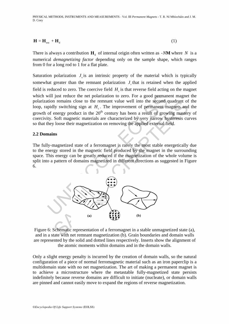
There is always a contribution dH of internal origin often written as -NM where N is a numerical demagnetizing factor depending only on the sample shape, which ranges from 0 for a long rod to 1 for a flat plate. Saturation polarization sJ is an intrinsic property of the material which is typically somewhat greater than the remnant polarization rJ that is retained when the applied field is reduced to zero. The coercive field cH is that reverse field acting on the magnet which will just reduce the net polarization to zero. For a good permanent magnet the polarization remains close to the remnant value well into the second quadrant of the loop, rapidly switching sign at cH . The improvement of permanent magnets and the growth of energy product in the 20th century has been a result of growing mastery of coercivity. Soft magnetic materials are characterized by very narrow hysteresis curves so that they loose their magnetization on removing the applied external field. 2.2 Domains The fully-magnetized state of a ferromagnet is rarely the most stable energetically due to the energy stored in the magnetic field produced by the magnet in the surrounding space. This energy can be greatly reduced if the magnetization of the whole volume is split into a pattern of domains magnetized in different directions as suggested in Figure 6.
Figure 6: Schematic representation of a ferromagnet in a stable unmagnetized state (a), and in a state with net remnant magnetization (b). Grain boundaries and domain walls
are represented by the solid and dotted lines respectively. Inserts show the alignment of the atomic moments within domains and in the domain walls.
Only a slight energy penalty is incurred by the creation of domain walls, so the natural configuration of a piece of normal ferromagnetic material such as an iron paperclip is a multidomain state with no net magnetization. The art of making a permanent magnet is to achieve a microstructure where the metastable fully-magnetized state persists indefinitely because reverse domains are difficult to initiate (nucleate), or domain walls are pinned and cannot easily move to expand the regions of reverse magnetization.

UNESCO – EOLS
S
SAMPLE C
HAPTERS
PHYSICAL METHODS, INSTRUMENTS AND MEASUREMENTS - Vol. III Permanent Magnets - T. R. Ní Mhíocháin and J. M. D. Coey
©Encyclopedia Of Life Support Systems (EOLSS)
2.3 Flux Density and Energy Product The purpose of any magnet application is to create a field in a region of space adjacent to the magnet known as the airgap; in other words, to deliver magnetic flux to this region. In free space, the flux density B (also known as the induction or B-field) is simply defined by
0µ=B H (2) but in the magnet itself, the B-field is quite different from the H-field, as indicated in Figure 7.
Figure 7: Magnetic field H and flux density B due to a uniformly-polarized bar-shaped permanent magnet of polarization J . Equation 3 is illustrated at point P.
The three quantities are related by
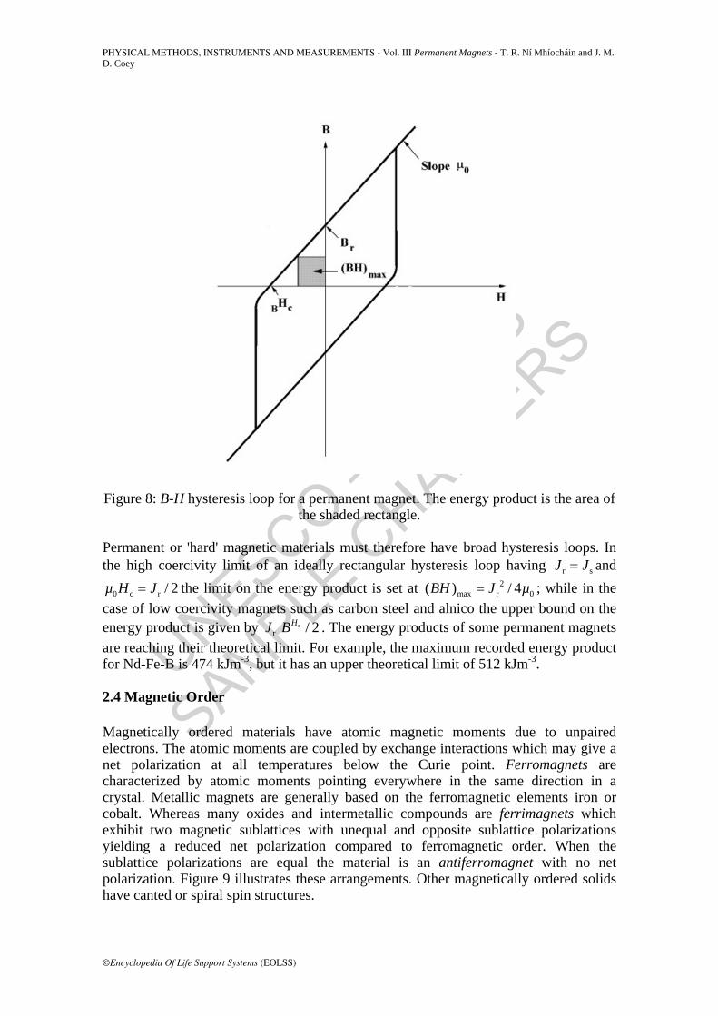
0µ= +B H J . (3) so that B and H are not necessarily proportional or even parallel there. Note that J and H are approximately opposite in direction within the material, so that the natural state of the magnet is represented by a point in the second quadrant of the ( )J H curve of Figure 5 that depends only on the magnet shape. Engineers often consider the B:H loop (Figure 8), rather than the J:H loop. The coercivity cHB on the B:H loop is smaller than cH , but the remanence is the same, r rB J= . The maximum energy product, denoted by the symbol max( )BH , has a simple interpretation; it is the area of the largest rectangle that can be inserted in the second quadrant of the BH loop, as shown in Figure 8. This indicates the total energy generated by the magnet in the airgap, and thus provides a measure of its usefulness.
UNESCO – EOLS
S
SAMPLE C
HAPTERS
PHYSICAL METHODS, INSTRUMENTS AND MEASUREMENTS - Vol. III Permanent Magnets - T. R. Ní Mhíocháin and J. M. D. Coey
©Encyclopedia Of Life Support Systems (EOLSS)
Figure 8: B-H hysteresis loop for a permanent magnet. The energy product is the area of the shaded rectangle.
Permanent or 'hard' magnetic materials must therefore have broad hysteresis loops. In the high coercivity limit of an ideally rectangular hysteresis loop having r sJ J= and
0 c r / 2µ H J= the limit on the energy product is set at 2max r 0( ) / 4BH J µ= ; while in the
case of low coercivity magnets such as carbon steel and alnico the upper bound on the energy product is given by c
r / 2HJ B . The energy products of some permanent magnets are reaching their theoretical limit. For example, the maximum recorded energy product for Nd-Fe-B is 474 kJm-3, but it has an upper theoretical limit of 512 kJm-3. 2.4 Magnetic Order Magnetically ordered materials have atomic magnetic moments due to unpaired electrons. The atomic moments are coupled by exchange interactions which may give a net polarization at all temperatures below the Curie point. Ferromagnets are characterized by atomic moments pointing everywhere in the same direction in a crystal. Metallic magnets are generally based on the ferromagnetic elements iron or cobalt. Whereas many oxides and intermetallic compounds are ferrimagnets which exhibit two magnetic sublattices with unequal and opposite sublattice polarizations yielding a reduced net polarization compared to ferromagnetic order. When the sublattice polarizations are equal the material is an antiferromagnet with no net polarization. Figure 9 illustrates these arrangements. Other magnetically ordered solids have canted or spiral spin structures.

UNESCO – EOLS
S
SAMPLE C
HAPTERS
PHYSICAL METHODS, INSTRUMENTS AND MEASUREMENTS - Vol. III Permanent Magnets - T. R. Ní Mhíocháin and J. M. D. Coey
©Encyclopedia Of Life Support Systems (EOLSS)
Figure 9: Illustration of (a) ferromagnetic, (b) ferrimagnetic and (c) antiferromagnetic order in a solid. The arrows represent atomic moments.
- - -
TO ACCESS ALL THE 56 PAGES OF THIS CHAPTER, Visit: http://www.eolss.net/Eolss-sampleAllChapter.aspx
Bibliography
J. F. Herbst, (1991) R2Fe14B Materials, Intrinsic Properties and Technological Applications. Reviews on Modern Physics, 63 , 819-898 [A comprehensive review of the literature on 2 14Nd Fe B and related materials by one of their discoverers]
J. M. D. Coey (editor) (1996) Rare-Earth Iron Permanent Magnets, Oxford University Press, 522 pp. [A monograph including 11 chapters on various aspects of permanent magnet materials, processing and applications, each written by a leader in the field. Graduate level text.]
J. M. D. Coey and O Cugat. (1994) Construction and Evaluation of Permanent Magnet Variable Flux Sources, In Proceedings of the 13th International Workshop on Rare-Earth Magnets and their Applications, Birmingham , p.41-54 [Many of the flux sources outlined in the present article are presented in greater detail in these two papers.]
K. H. J. Buschow (1997) Magnetism and Processing of Permanent Magnet Materials. in Ferromagnetic Materials v.10 K. H. J. Buschow (editor), North Holland, Amsterdam , p.463-593 [An extended review, covering recent developments]
K. Halbach, (1980) Design of Permanent Multipole Magnets with Oriented Rare Earth Cobalt Material, Nuclear Instrumentation and Methods, 169, 1-6. [The original paper presenting the theory of multipole Halbach cylinder designs.]
K. J. Strnat, (1990) Modern Permanent Magnets for Applications in Electrotechnology, Proceedings of the IEEE, 78 , 923-926 [A short review by the father of samarium-cobalt magnets]
M. G. Abele,(1993) Structures of Permanent Magnets, Wiley, New York, 372 pp. [A detailed and intensively analytical study of static permanent magnet structures.]
O. Cugat, P. Hansson and J. M. D. Coey, (1994) Permanent Magnet Variable Flux Sources, IEEE Transactions on Magnetics, 30 , 4602-4604 and
P. Campbell, (1994) Permanent Magnet Materials and their Application, Cambridge University Press, London, 207 pp. [An accessible introduction to permanent magnet applications aimed at electrical

UNESCO – EOLS
S
SAMPLE C
HAPTERS
PHYSICAL METHODS, INSTRUMENTS AND MEASUREMENTS - Vol. III Permanent Magnets - T. R. Ní Mhíocháin and J. M. D. Coey
©Encyclopedia Of Life Support Systems (EOLSS)
engineers.]
R. J. Parker, (1990) Advances in Permanent Magnetism, J. Wiley, New York, 360 pp. [A topical update, now a little dated, with plenty of information for the design engineer. Written in cgs units]
R. Skomski and J. M. D. Coey, (1999) Permanent Magnetism, Institute of Physics, Bristol, 404 pp. [This textbook offers a thorough overview of all aspects of permanent magnetism, from theory to applications. Suitable for both graduate and undergraduate students.]
T. R. Ní Mhíocháin, D. Weaire, S. M. McMurry, J. M. D. Coey, (1999) Analysis of Torque in Nested Halbach Cylinders, Journal of Applied Physics, 86 , 6412-6424. [A paper providing an experimental, numerical and analytical study of the forces between Halbach cylinders.] Biographical Sketches Michael Coey is Professor of Experimental Physics at Trinity College, Dublin. His achievements include the discovery of the samarium-iron-nitrogen permanent magnets, the development of novel permanent magnet flux sources and coordination of the 'Concerted European Action on Magnets' from 1985-1995. He has written extensively on many aspects of magnetism. Current research interests include spin electronics and the cross-disciplinary area of magnetism and electrochemistry. Treasa Ní Mhíocháin received her doctorate for work on magnetism from Trinity College Dublin, where she had previously obtained a first class honors degree in Theoretical Physics. In the course of her studies she has won awards for work which she has presented at conferences on three continents and published in many scientific journals. Her research has focused on permanent magnet design, and numerical simulations of problems in magnetics. A keen teacher, she is especially interested in making science accessible to the general public.


![Permanent magnets Ferrite, ndFeB, alniCo & smCo … · NdFeB BLS Magnet [6] Permanent magnets BLS Magnet [7] Permanent magnets nDFeB magnets Grade Remanence Remanence Coercive force](https://img.pdfslide.us/doc/110x75/5b915de509d3f210288b8282/permanent-magnets-ferrite-ndfeb-alnico-smco-ndfeb-bls-magnet-6-permanent.jpg)