Embed Size (px)
Citation preview

ISSN (Print) : 2320-3765 ISSN (Online): 2278-8875
International Journal of Advanced Research in Electrical,
Electronics and Instrumentation Engineering
Vol. 7, Issue 2, February 2018
Load Frequency Control of Multi-Area
Power System with PI Controller
Indrajeet Pal, Amit Kumar*
Gautam Buddh Univesity, Greater Noida, India
Abstract: The main objective of load frequency control (LFC) is to regulate the electrical power supply of multi-
area power system network and change the system frequency and tie-line load. The load variation on a power system
being unpredictable drifts in frequency and voltage from their nominal values resulting in loss of generation due to
tripping of lines and even blackouts. Fluctuation is more in the single area system than two area systems because of
variations in the load are handled by one area only. Variation in the frequency is made to be zero by using a
secondary loop in both single areas in addition to two area systems. Three area systems also operate in a similar
manner like that of two a rea system. Frequency and voltage drifts can be minimized and kept within tolerable
limits by automatic generation control (AGC). LFC is utilized to minimize the transient deviations in these variables
like area, frequency and tie-line power interchange) and to ensure their steady state errors to be zeros. Automatic
generation control of a system consists of two parts; LFC and automatic voltage regulator (AVR). In this paper, a
simulation study is carried out to understand the operation of load frequency controller by developing model in
SIMULINK MATLAB.
Keywords: AGC; Tie line power; PI controller; One area; Two area; Three area power system; Load frequency
control
I. INTRODUCTION
Power system is very complicated electric network, in which the distributed load is transferred over a large area [1].
In power system network the frequency variation due to load disturbances and causes the power quality problems
with voltage and frequency [2]. In power system the load varies with respect to time, control these variations and
maintain the stability the power system controllers are designed. Complexity has been increased in power system
due to rapid development in the industries. To solve the complexity the control problem mainly has two divisions-
one is based on the active power controlling the frequency; whereas other is based on reactive power regulating the
voltage [3]. Active and the reactive power exist due to continuous variation in the loads. The main intention is keep
the variation in frequency and voltage constant. Frequency is dependent on active power and voltage varies as

reactive power. Controlling of frequency and active power is commonly known as Automatic Load Frequency
Control. ALFC deals with controlling generator real power output and its frequency. Other problem like parameters
and model uncertainties are the major problem for a controller designer. For the stability of power system there
should be a proper balance between the active power and the reactive power. A three phase AC current is used for
the distribution of the electricity.
In case of imbalance, frequency and voltage adopt a finite value leading to instability in power system. So an
enhanced controlling system is necessary to avoid all these variations and possession the voltage and frequency at
their standard values. Since variation in the frequency and voltage is due to the combined effect of active and the
reactive power [4]. Control issue is decoupled into two independent issues-one of active power and other is reactive
power control. In order to achieve interconnected operation of a power system, electrical energy system must be
maintained at a desired operating level characterized by nominal frequency, voltage profile and load flow
configuration. This is achieved by close control of real and reactive powers generated through the controllable
source of the system.
For efficient transmission and distribution proper balance of active and reactive power is essential otherwise the
power system may enter into instability mode. As a result of the imbalance, the frequency and voltage levels will
oscillate around the steady state values and settle down to a finite value after a long delay which is undesirable for
stability. Thus a control system is essential to cancel the effects of the random load changes and to keep the
frequency and voltage at the standard values. Although the active power and reactive power have combined effects
on the frequency and voltage, the control problem of the frequency and voltage can be decoupled; the frequency is
dependent on the active power while the voltage is highly dependent on the reactive power. Thus the control issue in
power systems can be decoupled into two independent problems; one is about the active power and frequency
control while the other is about the reactive power and voltage control. In power system, load is not at constant then
automatic frequency and voltage regulators are required at the generating stations to sustain a load. If any problems
arise between generation and demand, causes the system frequency to deviate from scheduled value. Thus high
frequency deviation may lead to system collapse. This necessitates an accurate and fast acting controller to maintain
constant nominal frequency [5]. The limitations of the conventional controls- Integral, PI, and PID are slow and lack
of efficiency in handling system non linarites.
II. BASIC STRUCTURE OF AUTOMATIC GENERATION CONTROL (AGC)
2.1. Governors
Governors are employed in power system for sensing the predisposition in frequency which is the result of the
modification in load and eliminate by changing the turbine inputs such as the characteristic for speed regulation (R)
and the governor time constant (Tg). If the varying in load occurs without the load reference then some part of the
alteration can be compensated by adjusting the valve/gate and the remaining portion of the alteration can be depicted
in the form of deviation in frequency. Governors are setup in the power system for detecting the partiality in
frequency which is the outcome of the alteration in load and then remove it by transmitting the turbine such as
feature of the governor time constant and speed regulation. Governors are utilizing in the power system network to
controls the velocity of turbine, controller, and increases frequency directive. The load is not constant; it changes
according the demand. In case power is not consistent, it results in poor power quality. The supervision framework
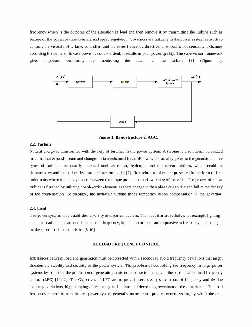
gives important conformity by monitoring the steam to the turbine [6] (Figure 1).
Figure 1: Basic structure of AGC.
2.2. Turbine
Natural energy is transformed with the help of turbines in the power system. A turbine is a rotational automated
machine that expands steam and changes in to mechanical force ∆Pm which is suitably given to the generator. Three
types of turbines are usually operated such as reheat, hydraulic and non-reheat turbines, which could be
demonstrated and maintained by transfer function model [7]. Non-reheat turbines are presented in the form of first
order-units where time delay occurs between the torque production and switching of the valve. The project of reheat
turbine is finished by utilizing double-order elements as there change in then phase due to rise and fall in the density
of the condensation. To stabilize, the hydraulic turbine needs temporary droop compensation in the governor.
2.3. Load
The power systems load establishes diversity of electrical devices. The loads that are resistive, for example lighting
and also heating loads are not dependent on frequency, but the motor loads are responsive to frequency depending
on the speed-load characteristics [8-10].
III. LOAD FREQUENCY CONTROL
Imbalances between load and generation must be corrected within seconds to avoid frequency deviations that might
threaten the stability and security of the power system. The problem of controlling the frequency in large power
systems by adjusting the production of generating units in response to changes in the load is called load frequency
control (LFC) [11,12]. The Objectives of LFC are to provide zero steady-state errors of frequency and tie-line
exchange variations, high damping of frequency oscillations and decreasing overshoot of the disturbance. The load
frequency control of a multi area power system generally incorporates proper control system, by which the area

frequencies can be bring back to its predefined value or very nearer to its predefined value as the tie line power,
when the sudden variation occurs in load.
IV. PI CONTROLLER
Most common utilized controllers are the proportional integral (PI) and proportional integral derivative (PID)
controller [13]. The PI controllers are used to improve the dynamic response as well as to reduce or eliminate the
steady state error [14]. The derivative controller adds a finite zero to the open loop plant transfer the function and
improves the transient response. PI is made up of two main components i.e. proportional and integral. However the
foremost standard controller are Proportional-Integral (PI) and Proportional Integral-derivative (PID) controller. PI
controller are used in industries, quantitatively around 95%. In case of proportional controller, it has a head start
output gain also the output response and desired response lies in between offset value.
The increasing proportional gain, offset can be reduced. PI controller offers the identical advantages of accelerated
response due to P-action and the zero regular position error due to I action. The error signals are amplified, mixed
and converted to a real power signal that controls the valve for generating a bulky signal [15]. PI-controller
controller provides the doublly compensations of highest towards P-action and non-stable state error because of I-
action.Through PI-control, improvement in the transient response can be observed and simultaneously steady state
error can be taken to zero value.
V. MODELLING OF AUTOMATIC GAIN CONTROL (AGC)
AGC plays a significant role in the power system by maintaining scheduled system frequency and tie line flow during
normal operating condition and also during small perturbations. Power system is a combination of generation,
transmission and distribution networks and loads. The active and reactive power demands from different loads vary
continuously. The change in real power demand affects the frequency while the change in the reactive power affects
the voltage. The main constraint on a system is to keep the deviations of the frequency and the voltage constant. In an
interconnected power system, as a power load demand varies randomly, both area frequency and tie-line power
interchange also vary. Load frequency control has a control feature in the speed governing linkage mechanism. AGC
, which have a speed governing linkage mechanism. In this mechanism if the generator speed is suddenly falls or
exceeds to its nominal pre- specified value then the speed governor sense the speed of generator and it will adjust the
steam water which is given to the turbine. Because ultimately the electromagnetic torque which produced by the
turbine is regulated then the generator speed and output power become regulate to its normal value. The main aim of
load frequency control is to minimize the transient variations in these variables and also to make sure that their steady
state errors is zero.
The objectives LFC are to minimize the transient deviations in these variables (area frequency and tie-line power
interchange) and to ensure their steady state errors to be zeros. When dealing with the LFC problem of power
systems, unexpected external disturbances, parameter uncertainties and the model uncertainties of the power system
pose big challenges for controller designer.
A. Single Area System with Primary Loop
Figure 2 shows the Automatic Load Frequency Control (ALFC) loop. Frequency is change with the load and
discriminated with reference speed setting. The frequency can be set to the desired value by making generation and
demand equal with the help of steam valve controller which regulate steam valve and increases power output from
generators. It serves the primary purpose for balancing the real power through regulating turbine output (ΔPm)
according the variation in load demand (ΔPo).
In Figure 2, ΔPref is the changing velocity reference placing and ΔPo is the disturbance. ALFC is known as the
primary ALFC feedback. It address the adjusting number one intention of actual energy stability by means of the
rotary engine output ΔPm to suit the change in load demand ΔPo.
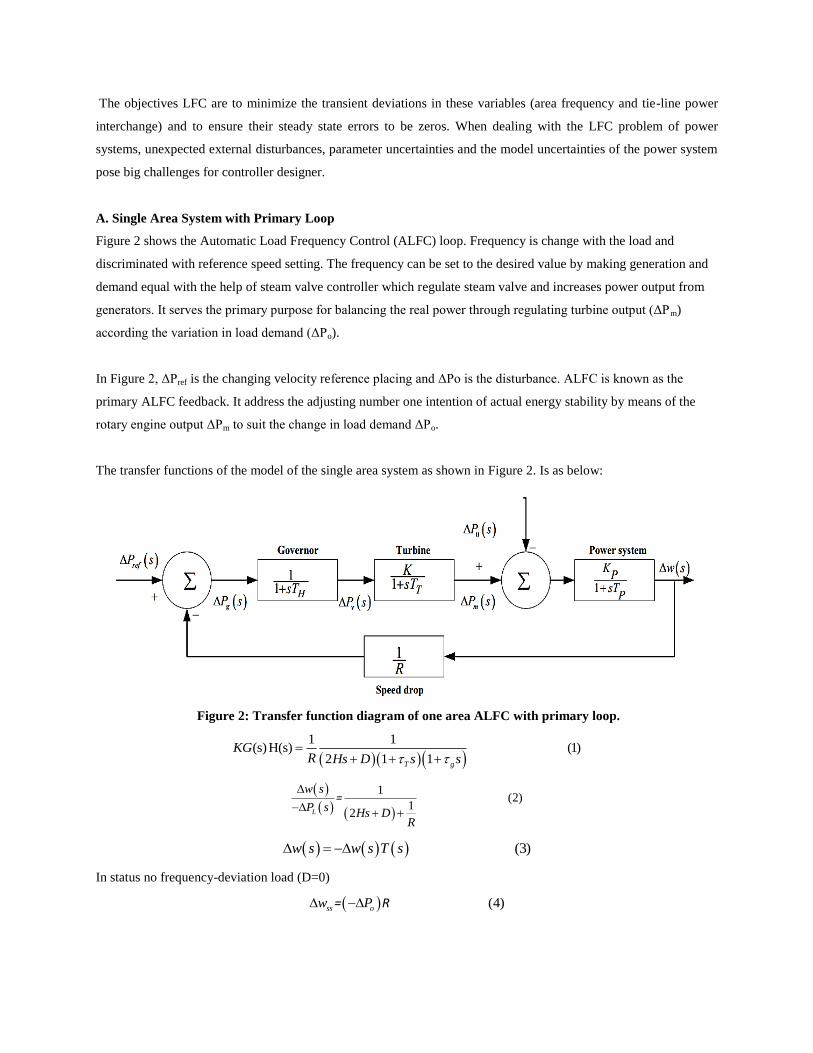
The transfer functions of the model of the single area system as shown in Figure 2. Is as below:
Figure 2: Transfer function diagram of one area ALFC with primary loop.
1 1
(s)H(s) (1)2 1 1
T g
KGR Hs D s s
1(2)
12L
w s
P sHs D
R
=
(3)w s w s T s
In status no frequency-deviation load (D=0)
(4)ss ow P = R

From the above equations the steady state value of new system frequency which is less than the initial value. It make
the frequency drift Δw to zero or to an acceptable value with the help of secondary loop for stable operation.
B. Single Area with Secondary Loop
Due to change in load there is change in the steady state frequency (Δw) so we need another loop apart from (Δw)
primary loop to convey the frequency to the initial value, before the load disturbance occurs. The integral controller
Which is responsible in making the frequency deviation zero is put in the secondary loop as shown in Figure 3.
Figure 3: Transfer function diagram of one area with secondry loop.
In Figure 2 ALFC loop, the first part of initial energy insure to maintean the change in load demand to ΔPo relate the
turbine product ΔPm But a change in load results the frequency deviation Δw there is steady state,the frequency
changed. In this future is met by basic contr0ller that form for frequency diversity reduced. AGC mutually the
analytical feedback is commonly known as ALFC.
The integral group transfer function:
r
1P (5)
1 ef ow P
DR
C. Double Area System with Primary Loop
This block is equal t0 the one area but the adding in ΔP12 . Consider that’s difference in load ΔPo area one, area two
frequencies of adjust to steady state value shown in Figure 4. Δw =Δw1=Δw2

Figure 4: Two area system with primary loop.
Suppose in load change ΔPo in area one. The frequency changing is the steady state equals all the areas. That is
Δw = Δw1 = Δw2
01 112
1 2
(6)P
P
When load increase in system, minimize the area frequency every system and dominent to charging of intrconnected
line energy. If ΔP12 sign change then energy goes from system two to system one.
02
1 2
(7)P
w
02 112 21
1 2
(8)P
P P
=
D. Double Area with Secondry Loop
The secondary control basically restores balance linking all area load generation which is possible by maintaining
the frequency at scheduled value. This is shown in Figure 5. Suppose there is a variation in load in area 1 then the
secondary control is in area 1 and not in area 2 so area control error (ACE) is being brought to use when steady-state
is reached and reference power set points, it will be zero. The secondary loop system iniataly restores the value
interconnected evey system load generation and maintain the possible frequency at a right time. The area
compromise for every system leed to consist of tie-line error and frequency will be linear combination.

In case of area1: 1 12
1(9)ACE p W =
In case of area2: 1 21 (10)ACE p W =
Figure 5: Two area system with secondary loop.
E. Three Area systems with Primary Loop
There is variation in steady state when varie in the load frequency (Δw ) so that next feedback away from initial
feedback to generate the frequency to the primary value. The system in 3 area system as to the 2 area system and
shown in Figure 6. This proportion integral system that is lie in the multi area system. They tie-line power the
interconnection make between the control system frequency change in the three areas is as follows:
1 1
1 1
1
(s) (13)
11 1
p
p
t
R K m
K s Ki RR s sT
sTg sTp
1F
K2/S
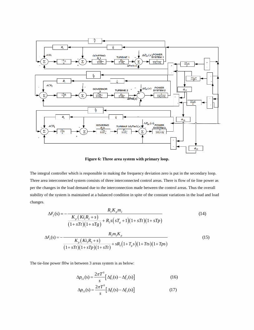
Figure 6: Three area system with primary loop.
The integral controller which is responsible in making the frequency deviation zero is put in the secondary loop.
Three area interconnected system consists of three interconnected control areas. There is flow of tie line power as
per the changes in the load demand due to the interconnection made between the control areas. Thus the overall
stability of the system is maintained at a balanced condition in spite of the constant variations in the load and load
changes.
2 2
2
1 2
2
(s) (14)
1 1 11 1
p
p
g
R K m
K Ki R sR s sT sTt sTp
sTt sTg
F
3 3
3
3 3
3
(s) (15)
1 1 11 1 1
p
p
g
R m K
K Ki R ssR T s Tts Tps
sTt sTp sTt
F
The tie-line power fl0w in between 3 areas system is as below:
0
12 1 2
2(s) (s) (s) (16)
Tp f f
s
0
13 1 3
2(s) (s) (s) (17)
Tp f f
s

0
23 2 3
2(s) (s) (s) (18)
Tp f f
s
F. Three Area System with Secondary Loop
The control in three area system is like the two area system and is shown in Figure 7. The integral control loop
which is used in the single area system and two area system can also be related to the three area systems. Due to
change in load there is change in the steady state frequency so we need another loop apart from primary loop to
make the frequency to the initial value, before the load disturbance occurs.
Figure 7: Three area system with secondry loop.
Three different areas are asume to be equal. In case of interlinked system of different power, the quantities
1 2 112 23 23
2 3 3
, r r r
r r r
a a ap p and p
a a a
are considered. This idea is presented by Elgerd and Fosha.
VI. SIMULATION RESULT OF MULTIAREA SYSTEM
6.1. One Area with Primary Loop
Figure 8 shows that the change in load causes alteration in speed and that cause deviation in frequency.
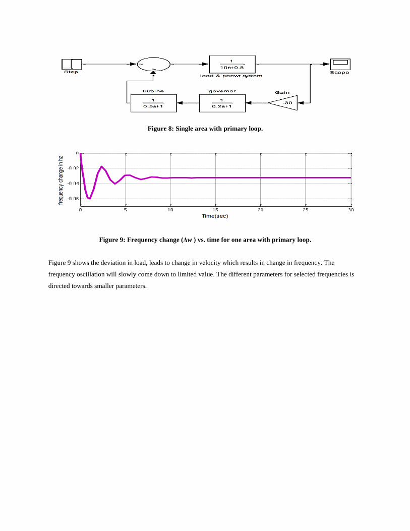
Figure 8: Single area with primary loop.
Figure 9: Frequency change (Δw ) vs. time for one area with primary loop.
Figure 9 shows the deviation in load, leads to change in velocity which results in change in frequency. The
frequency oscillation will slowly come down to limited value. The different parameters for selected frequencies is
directed towards smaller parameters.

B. One Area with Secondary Loop
Figure 10: Simulink model of one area with secondary loop
The secondary loop which a single area system with an controller used gain to balance reference signal to adopted
the signal to ΔPref turn arround Δw to 0 (Figure 10). The simulati0n output of one space within the controller loop
and therefore frequency is changes that are created 0 because of the controller loop (Figure 11).
Figure 11: Simulation output of one area with secondary loop.
B. Double Area with Primary Loop
Figure 12 presents that the two systems are being interrelated so the drifts in the frequency of the two are liable to
settle down to similar value soon after a few oscillations. The two mechanical inputs changes to minimize the
inequality power connecting electrical load in area 1 as well as the mechanical inputs. Area 2 is capable to generate
excessive power to distribute the variation in load in area 1.

Figure 12: Simulation daigram of double area with primary feedback.
Figure 13: Frequency change vs. time.
Figure 14: Output power deviation vs. time.
Figure 12 represent the ALFC of double-area with the primary loop Figure 13 as the both the part are interlinked,
Figure 14 presents the frequency oscillations of the two area system, after small oscillation the frequency achieve
steady state position. The mechanical inputs of double systems are minimizing the different energy in mechanical
inputs and the electrical load in area1. Although we get same results as area 1 but stability is improved with
interconnection.
Scope 1

D. Two Area System with Secondary Loop
Two area systems by using secondary loop are shown in Figure 15. The secondary loop is responsible for the
minimization of drifts in frequency to zero as shown in Figure 16. By changing the secondary loop gain we can see
the variation in the system dynamic response characteristics through tie line power as given away in Figure 17. We
have taken the values of the different parameters for modeling the Simulink model and its successful operation to
obtain the desired results.
Figure 15: Simulation diagram for double area.
Fig
Figure 16: Frequency change vs. time.
Figure 17: Simulation results in output power deviation vs. time.
Scope 1

C. Simulation Diagram of Three Areas with Primary Loop
Three area interconnected systems without using secondary loop is given in Figure 18. Figure 19 presents the
settling down of frequency to a finite value which is less than the actual frequency. Figure 20 shows the power
change due to tie-line on account of the deviation in the load.
Figure 18: Three areas without secondary loop.
Figure 19: Frequency deviation vs. time.
Figure 20: Simulation results output power deviation vs. time in three area system.
Three area systems with primary loop are given in Figures 19 and 20 and presents the stability is gain of the inter-
connection of power system.
D. Simulink Model of Three Areas with Secondary Loop

The model for the three area system including the secondary control is given below in Figure 21. The results of the
variation in frequency as well as tie line power output with respect to time are being shown in Figures 22 and 23.
The system operates in a similar way to that of the two area system, taking into consideration the changes in the
load.
Figure 21: Three areas by using secondary loop.
Figure 22: Frequency changes vs. time.
Figure 23: Power deviation vs. time.

VIII. CONCLUSION
A simulation study of single area, two areas and three areas as a multi system with automatic generation and control
is carried out with models developed in SIMULINK MATLAB. The system experiences frequency drift following a
load disturbance and it is mainly due to the mismatch between the electrical load and the mechanical input to the
turbine. All these aforesaid systems are controlled with conventional PI controller. The performance of PI controller
has been compared frequency deviation of three different area systems. PI controller shows the best performance of
settling time less frequency deviation and minimum oscillations. The system encounters drifts in the frequency
succeeding a disturbance in the load and it is primarily because of the mismatch involving the electrical load as well
as the mechanical input which is given to the prime mover/turbine. The system oscillation is serious in single area
system compared to two area and three area system because all the load change in load is to be met by only one area.
Also, using the secondary loop in single area as well as the two areas and three area systems the change in frequency
is brought to zero. The simulation of these systems has been carried out and results analyzed. The operation of single
area and two area systems with and without secondary loops are very well depicted through simulation models. The
advantage of interconnection is best understood by comparing the results of single area, two area and three area
systems. It can be seen that the oscillations due to change in load in any area is damped down quickly because of tie
line power flow. It can also be observed that the dynamic response is mainly governed by the secondary loop and
hence design criteria of which is extremely vital for efficient implementation.
IX. REFERENCES
[1] Kundur P; Power System Stability & Control. New York McGraw Hill 1994; 418-448.
[2] Amit K; Nidhi SP; Ansari MA; Mitigation Voltage Sag/Swell, Harmonic Compensation Using Self-Supported
DVR. Ist IEEE International Conference on Power Electronics, intelligent Control and Energy Systems 2016; 393-
399.
[3] Nagrath IJ; Kothari DP; Modern power system analysis. THM 1993.
[4] Usman A; BP Divakar; Simulation study of load. Frequency control of single and two area systems. IEEE Global
Humanitarian Technology Conference 2012; 214-219.
[5] Nanda J; Mishra S; Saikia LC; Maiden Application of Bacterial Foraging Based Optimization Technique in
Multiarea Automatic Generation Control. IEEE Transactions on Power System, 2009; 22: 602-609.
[6] Nanda J; Kaul BL; Automatic generation control of an interconnected power system. Proc. Inst. Elect. Eng 1978;
125: 385-390.
[7] Nanda J; Mangla A; Suri S; Some new finding on automatic generation control of an interconnected
hydrothermal system with conventional controller. IEEE Trans. Energy Convers 2006; 21: 187-194.
[8] Elegerd Ol; Fosha C; Optimal megawatt frequency control of multi area electric energy system. IEEE Trans.
Electric Power Apparatus System 1970; 89: 556-563.

[9] Mohamed M; Ismail MA; Mustafa H; Load Frequency Control Adaptation Using Artificial Intelligent Technique
for One and Two Different Areas Power System. International Journal of Control, Automation and System 2012; 1.
[10] Syamala J; Naidu LES; Load Frequency Control of Multiarea Power System Using PI, PID, and Fuzzy Logic
Controlling Technique. International Journal of Innovative Research in Science, Engineering and Technology 2014;
3: 1.
[11] Nilay NS, Adiya DC, Dwij, Anant RS, Automatic load frequency control of two area power systems with
conventional and fuzzy logic control. IJRET: International Journal of Research in Engineering and Technology
2012; 1.
[12] Poonam R; Ramavtar J; Automatic load frequency control of multi-area power system using ANN controller
and genetic algorithm. International Journal of Engineering Trends and Technology 2013; 4; 9.
[13] Dharmendra J; Bhaskar MK; Shyam KJ; Deepak B; Analysis of load frequency control problem for
interconnected power system using PID controller,” International Journal of Emerging Technology and Advanced
Engineering, Vol. 4, Issue 11, Nov. 2014.
[14] Wadhwa CL; Electrical power system. New Age International Publisher 6th
Edition.
[15] Nagrath IJ; Gopal M; Control System Engineering. New Age International Publisher New Delhi.

![Frequency Regulation in Hybrid Power Systems load frequency control (ALFC) in the system [1]. The study in this paper involves the design of load frequency controller (LFC) which maintains](https://img.pdfslide.us/doc/110x75/5b5038167f8b9a166e8e0d82/frequency-regulation-in-hybrid-power-systems-load-frequency-control-alfc-in-the.jpg)