Embed Size (px)
Citation preview

ISSN(Online): 2319-8753 ISSN (Print): 2347-6710
International Journal of Innovative Research in Science, Engineering and Technology
(A High Impact Factor, Monthly, Peer Reviewed Journal)
Visit: www.ijirset.com
Vol. 6, Issue 11, November 2017
Copyright to IJIRSET DOI:10.15680/IJIRSET.2017.0611012 21101
Industrial Case Study on Construction Processes at KMML
Radhu Chandini Department of Civil Engineering, T.K.M. College of Engineering, Kollam, India
ABSTRACT:The Kerala Minerals and Metals Ltd. (KMML) is a public sector undertaking, fully owned by the Govt. of Kerala, located at Sankaramangalam, Chavara, Kollam. KMML is the only integrated plant in the world of Titanium chemicals and metals that undertakes mining to manufacture to marketing at one complex.The industrial training programme at the civil engineering department of MS plant at KMML helped in having a clear picture of the basic processes going on in a civil engineering construction. This programme provided detailed descriptions on basic processes like concreting, reinforcement detailing, calculation of the amount of raw materials required etc. This report summarises the major construction activities at KMML. . KEYWORDS:Chemicals, Construction, Reinforcement, Titanium,
I. INTRODUCTION
KMML have three running plants in the complex.The Titanium di-oxide pigment (TiO2) manufacturing plant - TiO2 is used for manufacturing, paints, printing inks, plastic, paper, Rubber, textiles, Ceramics, Cosmetics etc.Titanium sponge plant (TSP)-Titanium sponge is used in Aero space Industry, Ocean Industry, chemical industry, Automobile and Rail Road, Civil Engineering and construction, sports and consumables, Medical and medicate etc.Mineral Separation Plant (MSP) Mineral separation plant separate valuable minerals, Ilmenite, Rutile, Leucoxene, zircon, SIllimanite etc. form the raw sand collected at sea beach and by mining. This case study entailsthe study at MSP where major civil works for industrial buildings are going on.
II. CIVIL CONSTRUCTIONS AT MS PLANT III.1.FOUNDATION FOR WET TABLE
FIG.1THE ON GOING CONSTRUCTION OF WET TABLE FOUNDATION AT MS PLANT

ISSN(Online): 2319-8753 ISSN (Print): 2347-6710
International Journal of Innovative Research in Science, Engineering and Technology
(A High Impact Factor, Monthly, Peer Reviewed Journal)
Visit: www.ijirset.com
Vol. 6, Issue 11, November 2017
Copyright to IJIRSET DOI:10.15680/IJIRSET.2017.0611012 21102
FIG.2.SECTIONAL ELEVATION OF WET TABLE FOUNDATION
FIG.3.FOUNDATION PLAN OF WET TABLE

ISSN(Online): 2319-8753 ISSN (Print): 2347-6710
International Journal of Innovative Research in Science, Engineering and Technology
(A High Impact Factor, Monthly, Peer Reviewed Journal)
Visit: www.ijirset.com
Vol. 6, Issue 11, November 2017
Copyright to IJIRSET DOI:10.15680/IJIRSET.2017.0611012 21103
FIG.4.FOUNDATION DETAILS-WET MILL
The figure above shows the construction of wet table going on at mineral separation plant. Mat foundation is used .Mat foundation is also known as flat foundation, It is a concrete slab which cover the entire area below the building and support all columns and walls. Mat foundation can face large settlement without causing any harm to the super structure, since the whole structure is resting on single foundation. Mat foundation is used when the soil is soft clay or made up land or marshy land with low bearing capacity, when the building loads are very high, when there are chances of differential settlement or possibility of earthquake, when columns are very close and in highly compressible soils. Here the load transferred to the foundation being excessive, thicker concrete beams were used to connect the columns for the better rigidity of the structure. Also heavy reinforced concrete slabs of enough thickness where provided. The reinforced bars used here were of diameters ranging from 10mm to 40mm.Pillars are connected by I-section to arrest vibrations of wet table. Retaining reinforcement are also provided. III.2.GO-DOWN Go-down is usually used to store different types of materials including heavy equipment and machinery. So different types of loads that can come in the go-down were taken into account by its design. The construction of godown floors, its walls and roofs were separately studied. III.3ROOF TRUSS
Its economical to use steel truss for span greater than 12m.Mild steel sections are available in all sizes and shapes and can be used as members of truss. Members of steel roof truss are either in compression or tension and have negligible bending. The stress in each member depends upon the span, type of truss, roof slope, material and centre-to-centre distance between the trusses. The roof of the go-down is made of Howe truss and a double sloping roof was chosen. The details of truss work are shown in the figure below. Corrugated iron sheets galvanized with zinc will be used as the covering for the sheet.

ISSN(Online): 2319-8753 ISSN (Print): 2347-6710
International Journal of Innovative Research in Science, Engineering and Technology
(A High Impact Factor, Monthly, Peer Reviewed Journal)
Visit: www.ijirset.com
Vol. 6, Issue 11, November 2017
Copyright to IJIRSET DOI:10.15680/IJIRSET.2017.0611012 21104
III.4.FLOORING REINFORCEMENT
Since the go-down is to carry heavy loads flooring reinforcement was provided at top and bottom. The reinforcement bars were tied together at proper intervals using tie bars of 10mm diameter, and at bottom and top chairs were provided. The diameter of the reinforcing bars provided is 25mm.
III.5.BRICK WALL
The go-down was provided with brick walls between the columns. English bond was used as it provides more strength. In English bond, alternate courses of stretchers and headers are laid. A queen closer is placed after the first header in the header course to stagger the vertical joints of successive courses. If the wall thickness is even multiple of ½ brick the same course shows header or stretcher in both front and back elevation. This type of bond is commonly used in all modes of construction.
FIG.5.CONSTRUCTION OF STORAGE GODOWN
FIG.6.ROOF TRUSS

ISSN(Online): 2319-8753 ISSN (Print): 2347-6710
International Journal of Innovative Research in Science, Engineering and Technology
(A High Impact Factor, Monthly, Peer Reviewed Journal)
Visit: www.ijirset.com
Vol. 6, Issue 11, November 2017
Copyright to IJIRSET DOI:10.15680/IJIRSET.2017.0611012 21105
FIG.7.ROOF TRUSS
FIG.8.FLOOR REINFORCEMENT
FIG.9.BRICK WALL
ISSN(Online): 2319-8753 ISSN (Print): 2347-6710
International Journal of Innovative Research in Science, Engineering and Technology
(A High Impact Factor, Monthly, Peer Reviewed Journal)
Visit: www.ijirset.com
Vol. 6, Issue 11, November 2017
Copyright to IJIRSET DOI:10.15680/IJIRSET.2017.0611012 21106
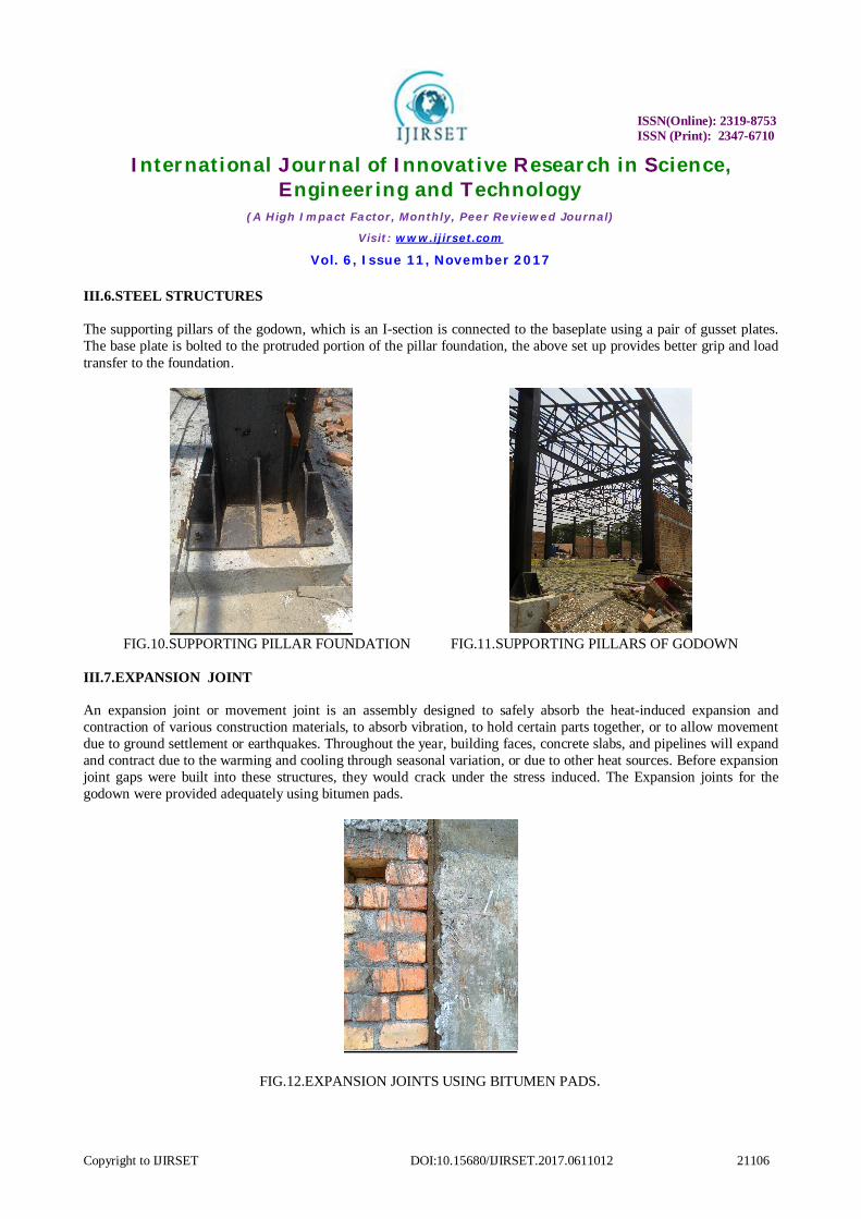
III.6.STEEL STRUCTURES The supporting pillars of the godown, which is an I-section is connected to the baseplate using a pair of gusset plates. The base plate is bolted to the protruded portion of the pillar foundation, the above set up provides better grip and load transfer to the foundation.
FIG.10.SUPPORTING PILLAR FOUNDATION FIG.11.SUPPORTING PILLARS OF GODOWN
III.7.EXPANSION JOINT An expansion joint or movement joint is an assembly designed to safely absorb the heat-induced expansion and contraction of various construction materials, to absorb vibration, to hold certain parts together, or to allow movement due to ground settlement or earthquakes. Throughout the year, building faces, concrete slabs, and pipelines will expand and contract due to the warming and cooling through seasonal variation, or due to other heat sources. Before expansion joint gaps were built into these structures, they would crack under the stress induced. The Expansion joints for the godown were provided adequately using bitumen pads.
FIG.12.EXPANSION JOINTS USING BITUMEN PADS.

ISSN(Online): 2319-8753 ISSN (Print): 2347-6710
International Journal of Innovative Research in Science, Engineering and Technology
(A High Impact Factor, Monthly, Peer Reviewed Journal)
Visit: www.ijirset.com
Vol. 6, Issue 11, November 2017
Copyright to IJIRSET DOI:10.15680/IJIRSET.2017.0611012 21107
III.8. SEDIMENTATION TANK
FIG.13.SEDIMENTATION TANK
Settling is theprocess operating here, by which particulates settle to the bottom of a liquid and form a sediment.Particles experience a force, either due to gravity or due to centrifugal motion, tend to move in a uniform manner in the direction exerted by that force.Gravity settling is where the particles will tend to fall to the bottom of the vessel, forming a slurry at the vessel base.For dilute particle solutions, two main forces are enacting upon particle. Primary force is an applied force, such as gravity, and a drag force that is due to the motion of the particle through the fluid. The applied force is not affected by the particle's velocity; the drag force is a function of the particle velocity. Settling Model
FIG.14.SETTLING MODEL
A particle that is just removed has a settling velocity v0. Vs = settling velocity of the particle Vl = horizontal velocity of liquid flow
This trajectory represents a particle which has a settling velocity v0 v0 = h / t = Q / A Where: t = V/Q A = surface area of the basin Critical Settling Velocity and Overflow Rate v0expressed in units of velocity (ft/s) is the critical settling velocity

ISSN(Online): 2319-8753 ISSN (Print): 2347-6710
International Journal of Innovative Research in Science, Engineering and Technology
(A High Impact Factor, Monthly, Peer Reviewed Journal)
Visit: www.ijirset.com
Vol. 6, Issue 11, November 2017
Copyright to IJIRSET DOI:10.15680/IJIRSET.2017.0611012 21108
FIG.15.SETTLING MODEL
v0 expressed in units of flow per unit area is called the Overflow rate.
The critical settling velocity and the overflow rate are the same number, but proper units should be used to express each. Since smaller particles have lower settling velocities, if you want to remove smaller particles in the settling basin you have to have a lower overflow rate.
TYPICAL DIMENSIONS OF SEDIMENTATION TANK ______________________________________________________ Description Dimensions Range Typical ______________________________________________________ Rectangular Depth, m 3-5 3.5 Length, m 15-90 20-40 Width, m 3-24 6-10 Circular Diameter, m 4-60 12-45 Depth, m 3-5 4.5 Bottom Slope, mm/m 60-160 80
______________________________________________________
IV.CONCLUSION KMML has grown over the years due to its state of art technology. The MS plant is the primary raw material extracting plant supported by an experienced technical and administrative team. The industrial training programme at the civil engineering department of MS plant at KMML helped in having a clear picture of the basic processes going on in a civil engineering construction. This programme provided detailed descriptions on basic processes like concreting, reinforcement detailing, calculation of the amount of raw materials required etc. I also witnessed some of the major constructions going on there like construction of wet table foundation, construction of the godown, sedimentation tank, erection of steel structures etc. The training programme also enabled me in having very useful interactive sessions with the engineers in the department wherein I cleared the basic doubts in the field and the chief engineer shared his professional experiences. The training programme was indeed a useful and inspiring one in my professional course.
REFERENCES
1. Civil Engineering Department Manual ,KMML,Kollam,Kerala. 2.Shetty M.S. ,Concrete technology Theory and Practice, S.Chand& Company Ltd. New Delhi.


![INTEGRAL UNIVERSITY · of chocolate mass. UNIT-V [8] Sugar Confectionery manufacture: General technical aspects of industrial sugar confectionery manufacture, Manufacture of high](https://img.pdfslide.us/doc/110x75/60522b55e4d7204ba61ef415/integral-university-of-chocolate-mass-unit-v-8-sugar-confectionery-manufacture.jpg)