Embed Size (px)
Citation preview
ISSN(Online) : 2319 - 8753
ISSN (Print) : 2347 - 6710
International Journal of Innovative Research in Science,
Engineering and Technology
(An ISO 3297: 2007 Certified Organization)
Vol. 4, Special Issue 6, May 2015
Copyright to IJIRSET www.ijirset.com 1244
Analysis of Grid Inverter System Using
LCL Filter Based on Active and
Passive Damping Methods
R.Raja1, Dr.C.Nagarajan
2
Assistant Professor, Department of Electrical and Electronics Engineering, Salem College of Engineering
and Technology, Salem, Tamil Nadu, India1
Professor and Head, Department of Electrical and Electronics Engineering, Muthayammal Engineering College,
Namakkal, Tamil Nadu, India2
ABSTRACT : The shortage of electric power is the major problem now-a-days. As the conventional energy sources
are depleting at a faster rate, there is an urgent need to investigate the alternative energy sources which help to solve
the problem. The Renewable Energy Sources (RES) like wind, solar, tidal, bio mass etc., serve this purpose. But these
are intermittent in nature and cannot be integrated to the present utility grid directly. Thus, to overcome the above
problem power electronic converters are used. These converters should be controlled in such way that the stability of
the overall system is maintained. In this project, the control of grid connected inverter with LCL filter is studied. The
LCL filter is an effective solution for the interconnection of the RES to the grid but suffers from the problem of
resonance. To overcome the above drawback active and passive damping methods are proposed. And also a
control strategy to reduce the lower order harmonics is proposed. The proposed control strategy is simulated in
MATLAB SIMULINK environment.
KEYWORDS : LCL filter, active and passive damping methods, shunt and series connected LCL filter, reducing low
order harmonics.
I. INTRODUCTION
At present, there is an exponential rise in the power demand and to meet this demand the existing energy resources are
not sufficient. And also these resources are depleting day- by-day. So there is an urgent need to develop the power
generation from Renewable Energy Sources (RES) which provide a reliable alternative for the conventional energy sources.
These also have the advantage of cleaner energy production by reducing carbon emission, thereby being
environmental friendly. But the main drawback of these RES is their intermittent nature, which causes difficulty in
extracting power all the time in a day. As these are the only option left to meet the increasing energy demand, they
(RES) should be modeled in such a way to overcome this drawback. These RES are synchronized to the grid through a dc-
link and an inverter. To ensure stable operation of the grid, the voltage and frequency of the power injected by the RES
should match with that of the grid. To achieve this, perfect control of the grid-side inverter is required in spite of
the intermittent nature of RES. This project presents the modeling of the grid side inverter and proposes a control strategy
for better synchronization of the RES to the grid. The Renewable Energy Sources are connected to the utility grid through a
power electronic converter and a filter.
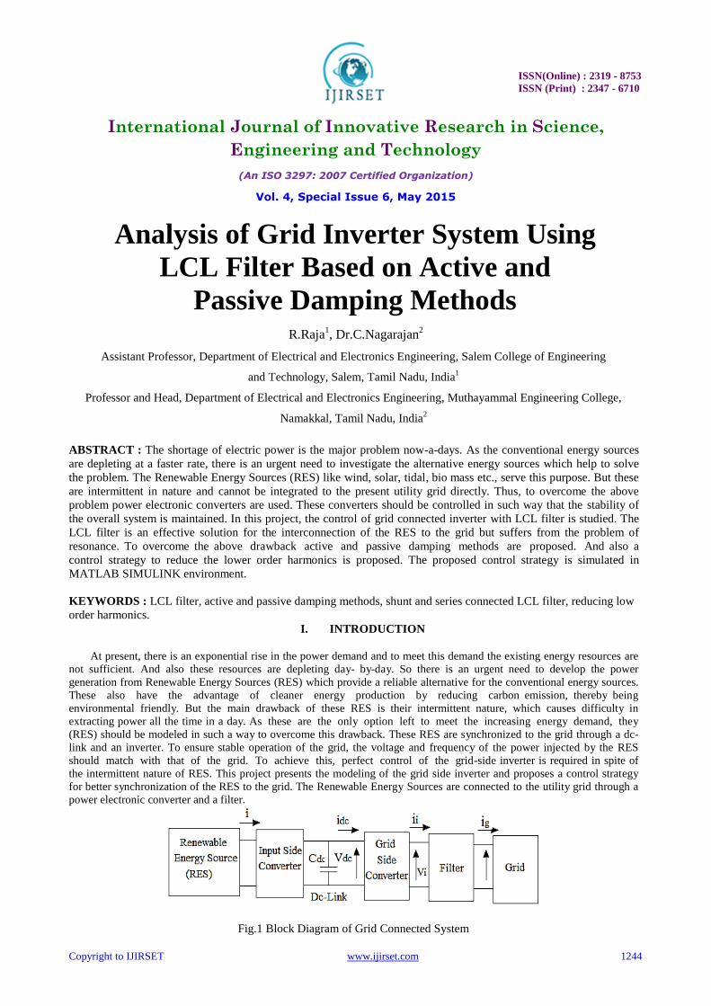
Fig.1 Block Diagram of Grid Connected System

ISSN(Online) : 2319 - 8753
ISSN (Print) : 2347 - 6710
International Journal of Innovative Research in Science,
Engineering and Technology
(An ISO 3297: 2007 Certified Organization)
Vol. 4, Special Issue 6, May 2015
Copyright to IJIRSET www.ijirset.com 1245
In Fig. 1 the RES may represent wind or solar panel, which generate either ac or dc. Its main aim is to extract
maximum power from the RES. It may contain a boost converter to boost the voltage levels to match with that of
the utility grid values. The control algorithms of input side converter include MPPT techniques to extract
maximum power from RES at every point of time. The DC-link is used for providing constant dc input voltage to the
grid-side converter. It contains a capacitor, Cdc for this purpose. The Grid-side Converter converts the dc power to ac
and feed it to the utility grid. The main aim of this converter is to maintain constant dc-link voltage to keep the
frequency and phase of output current same as grid voltage. In addition to the above main tasks, the grid-side
converter also regulates local voltage and frequency, compensates the voltage harmonics and may does active
filtering when required. Thus, to control the power injected into the grid, the control of grid-side converter is
of utmost important. But the output current from the inverter contains harmonics. So to filter out these harmonics a
filter is used at the output of the inverter.
II. MODELLING OF GRID CONNECTED INVERTER
The mathematical model of the grid-connected RES is necessary in order to simulate and study the performance
of the system at different operating conditions. The assumptions are (a) Three phase grid voltage is symmetrical,
stable and internal resistance is zero , (b) Three phase loop resistance and inductance are of the same value in all
phases, (c) Switching loss and on-state voltage drop are Neglected, (d) Effect of distributed parameters are neglected,
(e) Switching frequency of the rectifier is high enough. The circuit diagram of grid-connected inverter with LCL-filter
is shown in Fig. 2.1
Fig.2.1 Circuit-Diagram of Grid-Connected Inverter
The parameters of the Fig. 2.1 are as follows
TABLE-1. SYSTEM PARAMETERS
Symbol Parameter
Li Inverter side filter inductor
Lg Grid side filter inductor
Cf Filter capacitance
Rd Small damping resistance in series with the filter capacitance
Va , Vb , Vc Inverter side output voltages
Usa , Usb , Usc The grid side output voltages
Cdc Dc-link capacitance
Ipv Current from the PV-panel
Idc Current through dc-link capacitor
Ii Current from the inverter
Ig The current entering the grid
Vdc Voltage across dc-link capacitor

ISSN(Online) : 2319 - 8753
ISSN (Print) : 2347 - 6710
International Journal of Innovative Research in Science,
Engineering and Technology
(An ISO 3297: 2007 Certified Organization)
Vol. 4, Special Issue 6, May 2015
Copyright to IJIRSET www.ijirset.com 1246
From the circuit diagram by using Kirchhoff Law, the voltage and current equations in stationary frame can be written
as follows [6]-
(1)
(2)
(3)
Let the switching function of the inverter switches be defined as- SK = 1, if upper switch conducts and lower switch
blocks and Sk = 0, if lower switch conducts and upper switch blocks Where K=a, b, c From Fig. 1.2 on the dc-side,
(4)
(5)
(6)
Where isa, isb, isc are the currents in phases-a,b,c respectively coming out of the inverter . f the switching frequency is
much higher than the grid voltage frequency, then the switching function, Sk can be substituted by duty cycle, dk [1].
Thus, from equation (6)
- (7)
Converting the above equation in a-b-c reference frame to stationary reference frame (αβ) using the Park‟s
transformation matrix, the new equation obtained is-
- (8)
Where dα, dβ are the duty ratios of the inverter switches in α-β plane and iα, iβ are the inverter output currents in α-β
plane.
A. Proportional-Integral (PI) Controller
It contains a proportional gain Kp and an integrator with gain KI. The integral component helps in eliminating the
steady state error. The transfer function of the PI controller is-
(9)
The proportional and integral gain values are calculated by Symmetrical Optimum Method [4]. Even though the current
error turns to zero in steady state, it may appear in transient condition. This controller is mainly used in d-q reference
frame where the grid voltage and currents are dc variables. In d-q reference frame, the current equations are
given as [1].
Where Ls is the grid-inductance and Um is the maximum value of grid voltage. From above equations it is clear that
the system is strongly coupled and the design complexity Increases. So to reduce the complexity, the control is done in
stationary reference frame (α-β). In stationary reference control the advantage is that the number of control variables is
reduced. But in stationary reference frame control, the control variables are sinusoidal in nature. So PI controllers fail in

ISSN(Online) : 2319 - 8753
ISSN (Print) : 2347 - 6710
International Journal of Innovative Research in Science,
Engineering and Technology
(An ISO 3297: 2007 Certified Organization)
Vol. 4, Special Issue 6, May 2015
Copyright to IJIRSET www.ijirset.com 1247
removing the steady state error. As a consequence employment of other type of controllers is necessary. Due this
drawback a new controller known as proportional resonant (PR) controller gains large popularity in current regulation
for grid connected inverter system.
B. Proportional-Resonant (PR) Controller
To overcome the drawback of the PI controller, PR controllers are proposed. The advantage of PR controller is the
possibility of implementing harmonic compensator without affecting the controller dynamics [3]. The transfer function
of an ideal PR controller is
(12)
But this has an infinite gain at the frequency ω rad/s. So a cut-off frequency ωc is introduced to obtain finite gain and
also to reduce sensitivity towards utility grid frequency variations by adjusting the band-width. Thus, the transfer
function of non-ideal PR controller is
With the flexibility of tuning the resonant frequency, the PR controller can be used for selectively compensating the
low-order harmonics. The gain values are calculated by using the formulae give in [4].
C. Control Strategy
The main aim of the control strategy is to obtain unity power factor operation and to reduce the harmonics in the
current injected into the grid. To achieve these objectives, the grid voltage is aligned along the d-axis of the 2-ϕ rotating
coordinates. So Vd = Vg and Vq = 0 The grid voltage and current when expressed in d-q reference frame can be written
as
(14)
(15)
Three-phase complex power injected to the grid is given as
(16)
Thus, the complex power in d-q reference frame is given as
(17)
This shows that active power injected to the grid depend on „Id‟ and reactive power depends on „Iq‟. Thus, the active
and reactive powers are controlled independently. To make the reactive power exchange to zero, the reference value
Iq * is set to zero. The current Id is controlled to meet the active power demand.
(18)
III. SIMUALATION AND RESULTS
The overall control strategy of grid-interfaced inverter with active and passive damping. Methods for LCL-type
filter configuration is studied and analyzed using MATLAB Simulink environment. The system parameters considered
for this study are given in Table-2. The obtained results during steady state and transient conditions are discussed in
this section.

ISSN(Online) : 2319 - 8753
ISSN (Print) : 2347 - 6710
International Journal of Innovative Research in Science,
Engineering and Technology
(An ISO 3297: 2007 Certified Organization)
Vol. 4, Special Issue 6, May 2015
Copyright to IJIRSET www.ijirset.com 1248
Fig.3.1 Simulation for active and damping method
TABLE-2. SYSTEM PARAMETERS
Symbol Parameter Value
Ppv System power 100 kW
Vdc Dc-Link Voltage 600 V
Ug Grid Voltage 300 V (Line to Line)
Cdc Dc- Link Capacitance 13400 µF
Fs Switching Frequency 4.5 kHz
Li Inverter Side Inductance 2 mH
Lg Grid Side Inductance 1.8 mH
Cf Filter Capacitance 4.7 µF
Rd Damping Resistance 2.2 Ω
C1 Damping Capacitor 4.7 µF
D. During Steady State Conditions
The simulation results under steady-state condition for active and passive damping methods are illustrated in Fig.
3.1 and Fig. 3.2 respectively. Fig.3.1 (a) shows the three phase grid voltage and grid current waveforms under steady
state conditions using active damping method and they are almost close to sinusoidal waveforms. Fig.3.1 (b) depicts d
and q-axis grid current components and q-axis component is almost zero. And it implies that there is no reactive power
injected into the grid and it ensures unity power factor operation of the grid. The corresponding grid active and reactive
power response is shown in Fig.3.1 (c). Also the dc-link voltage is maintained constant at 600 V which is illustrated in
Fig.3.1 (d). With the help of active damping method, PWM VSI with LCL filter injects sinusoidal current into the grid.
As a result, THD of grid current is largely reduced (1.66%) and it is shown in Fig.3.1 (e). The corresponding steady
state response of passive damping method for LCL-type filter for grid-connected PMW VSI is shown Fig3.2.
(a)
(b)
ISSN(Online) : 2319 - 8753
ISSN (Print) : 2347 - 6710
International Journal of Innovative Research in Science,
Engineering and Technology
(An ISO 3297: 2007 Certified Organization)
Vol. 4, Special Issue 6, May 2015
Copyright to IJIRSET www.ijirset.com 1249
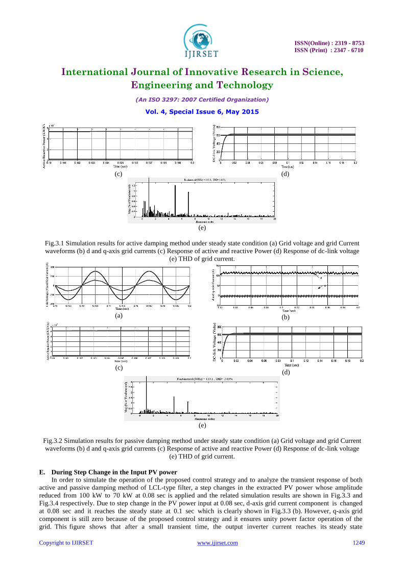
(c)
(d)
(e)
Fig.3.1 Simulation results for active damping method under steady state condition (a) Grid voltage and grid Current
waveforms (b) d and q-axis grid currents (c) Response of active and reactive Power (d) Response of dc-link voltage
(e) THD of grid current.
(a)
(b)
(c)
(d)
(e)
Fig.3.2 Simulation results for passive damping method under steady state condition (a) Grid voltage and grid Current
waveforms (b) d and q-axis grid currents (c) Response of active and reactive Power (d) Response of dc-link voltage
(e) THD of grid current.
E. During Step Change in the Input PV power In order to simulate the operation of the proposed control strategy and to analyze the transient response of both
active and passive damping method of LCL-type filter, a step changes in the extracted PV power whose amplitude
reduced from 100 kW to 70 kW at 0.08 sec is applied and the related simulation results are shown in Fig.3.3 and
Fig.3.4 respectively. Due to step change in the PV power input at 0.08 sec, d-axis grid current component is changed
at 0.08 sec and it reaches the steady state at 0.1 sec which is clearly shown in Fig.3.3 (b). However, q-axis grid
component is still zero because of the proposed control strategy and it ensures unity power factor operation of the
grid. This figure shows that after a small transient time, the output inverter current reaches its steady state

ISSN(Online) : 2319 - 8753
ISSN (Print) : 2347 - 6710
International Journal of Innovative Research in Science,
Engineering and Technology
(An ISO 3297: 2007 Certified Organization)
Vol. 4, Special Issue 6, May 2015
Copyright to IJIRSET www.ijirset.com 1250
value of 100 A, which is exactly equal to the reference value. This proves that the current loop controller along
with active damping method in the LCL-type filter is effective such that measured currents track their references
with constant dc-link voltage of 600 V (from the Fig.3.3 (c). Moreover, its dynamic behavior is satisfactory. In
addition, the active damping method with LCL-type filter injects sinusoidal current into the grid with lesser THD
(1.85% from the Fig.3.3 (d). The corresponding response of passive damping method with LCL-type filter for grid-
connected PWM VSI is illustrated in Fig.3.4.
(a)
(b)
(c)
(d)
Fig.3.3 Simulation results for active damping method during step change in the input PV power (a) Step change in
the input PV power (b) d and q-axis grid currents (c) Response of dc-link voltage (d) THD of grid current.
(a)
(b)
(c)
Fig 3.4 Simulation results for passive damping method during step change in the input PV power (a) d and q-axis grid
currents (b) Response of dc-link voltage (c) THD of grid current.
F. Comparative Analysis A comparative study between active and passive damping methods for LCL-type filter is discussed here. With
reference to Table-3 it is found that, the active damping method is superior over passive damping method and it
ensures almost sinusoidal current injection into the grid with reduced THD. Also the loss befalling in the passive
damping method are more with the introduction of extra physical components, which further reduces the overall
efficiency of grid-connected inverter system.

ISSN(Online) : 2319 - 8753
ISSN (Print) : 2347 - 6710
International Journal of Innovative Research in Science,
Engineering and Technology
(An ISO 3297: 2007 Certified Organization)
Vol. 4, Special Issue 6, May 2015
Copyright to IJIRSET www.ijirset.com 1251
TABLE-3THD OF GRID CURRENT COMPARISON
Type of
Damping
Steady-State
Condition
Source Dynamics
Condition
Active Damping 1.66% 1.85%
Passive Damping 2.03% 2.11%
IV. SIMULATION RESULTS FOR SHUNT CONNECTED LCL FILTER
The proposed control strategy is simulated in MATLAB SIMULINK environment and the results are discussed in
this section. The parameter values of the shunt connected LCL filter are given in Table-4
TABLE-4 SYSTEM PARAMETERS
Symbol Parameter Value
Ppv System power 100 kW
Vdc Dc-Link Voltage 600 V
Ug Grid Voltage 300 V (Line to Line)
Cdc Dc- link capacitance 13400 µF
Fs Switching frequency 4.5 kHz
L1 LCL Filter Inductance 1.2 mH
L2 LCL Filter Inductance 1.1 mH
Lg Grid Side Inductance 1.8 mH
Cf Filter capacitance 4.7 µF
Rd Damping resistance 2.2 Ω
C1 Damping capacitor 4.7 µF
A. During Steady State Conditions The simulation results under steady-state condition are illustrated in Fig. 4.1. Fig.4.2 (a) shows the three-phase
grid voltage and grid current waveforms under steady state conditions and they are almost close to sinusoidal
waveforms. Fig.4.1 (b) depicts d and q-axis grid current components and q-axis component is almost zero. And it
implies that there is no reactive power injected into the grid and it ensures unity power factor operation of the
grid. Also the dc-link voltage is maintained constant at 600 V which is illustrated in Fig.4.2 (c). The THD of grid
current is largely reduced (1.27%) when compared with series connected LCL-filter and it is shown in Fig.4.3 (d).
Thus, the fundamental component of the current injected to the grid has been increased, increasing the active power
supplied by the RES to the utility grid.
(a)
(b)
(c)
(d)
Fig.4.1 Simulation results under steady state condition (a) Grid voltage and grid Current waveforms (b) d and q-axis grid currents (c) Response of
DC-link voltage (d) THD of grid current.
ISSN(Online) : 2319 - 8753
ISSN (Print) : 2347 - 6710
International Journal of Innovative Research in Science,
Engineering and Technology
(An ISO 3297: 2007 Certified Organization)
Vol. 4, Special Issue 6, May 2015
Copyright to IJIRSET www.ijirset.com 1252
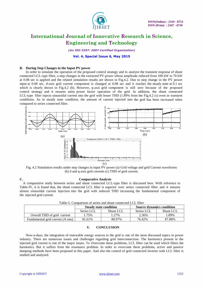
B. During Step Changes in the Input PV power
In order to simulate the operation of the proposed control strategy and to analyze the transient response of shunt
connected LCL-type filter, a step changes in the extracted PV power whose amplitude reduced from 100 kW to 70 kW
at 0.08 sec is applied and the related simulation results are shown in Fig.4.2. Due to step change in the PV power
input at 0.08 sec, d-axis grid current component is changed at 0.08 sec and it reaches the steady state at 0.1 sec
which is clearly shown in Fig.4.2 (b). However, q-axis grid component is still zero because of the proposed
control strategy and it ensures unity power factor operation of the grid. In addition, the shunt connected
LCL-type filter injects sinusoidal current into the grid with lesser THD (1.89% from the Fig.4.2 (c) even in transient
conditions. As in steady state condition, the amount of current injected into the grid has been increased when
compared to series connected filter.
(a)
(b)
(c)
Fig. 4.2 Simulation results under step changes in input PV power (a) Grid voltage and grid Current waveforms
(b) d and q-axis grid currents (c) THD of grid current.
C. Comparative Analysis
A comparative study between series and shunt connected LCL-type filter is discussed here. With reference to
Table-IV, it is found that, the shunt connected LCL filter is superior over series connected filter and it ensures
almost sinusoidal current injection into the grid with reduced THD increasing the fundamental component of
the injected grid current.
Table-5. Comparison of series and shunt connected LCL filter
Steady state condition Source dynamics condition
Series LCL Shunt LCL Series LCL Shunt LCL
Overall THD of grid current 1.75% 1.27% 2.36% 1.89%
Fundamental grid current (A rms) 81.61% 88.97% 76.42% 87.88%
V. CONCLUSION
Now-a-days, the integration of renewable energy sources to the grid is one of the most discussed topics in power
industry. There are numerous issues and challenges regarding grid interconnection. The harmonics present in the
injected grid current is one of the major issues. To Overcome these problems, LCL filter can be used which filters the
harmonics. But it suffers from the resonance problem. In order to overcome these problems, active and passive
damping methods have been proposed in this paper. And also the control of grid connected inverter with LCL filter is
studied and analyzed.

ISSN(Online) : 2319 - 8753
ISSN (Print) : 2347 - 6710
International Journal of Innovative Research in Science,
Engineering and Technology
(An ISO 3297: 2007 Certified Organization)
Vol. 4, Special Issue 6, May 2015
Copyright to IJIRSET www.ijirset.com 1253
REFERENCES
[1] Ma Liang; Zheng, T.Q., "Synchronous PI control for three phase grid-connected photovoltaic inverter," In Proc 2010 Chinese Control and
Decision Conference (CCDC ), pp.2302,2307, May 2010. [2] Perera, Brian K., et al. "Simulation model of a grid-connected single-phase photovoltaic system in PSCAD/EMTDC." Power System
Technology (POWERCON), 2012 IEEE International Conference on. IEEE, 2012. [3] Li, Bin; Zhang, Ming; Huang, Long; Hang, Lijun; Tolbert, Leon M., "A robust multiresonant PR regulator for three-phase grid-connected VSI
using direct pole placement design strategy," Applied Power Electronics Conference and Exposition (APEC), 2013 Twenty-Eighth Annual IEEE , vol., no., pp.960,966, 17-21 March 2013.
[4] Hong-Seok Song; Keil, R.; Mutschler, P.; van der Weem, J.; Kwanghee Nam, "Advanced control scheme for a single-phase PWM rectifier in
traction applications," Industry Applications Conference, 2003. 38th IAS Annual Meeting. Conference Record of the , vol.3, no., pp.1558,1565 vol.3, 12-16 Oct. 2003.
[5] Jiri Lettl, Jan Bauer, and Libor Linhart. “Comparison of Different Filter Types for Grid Connected Inverter” Progress In Electromagnetics
Research Symposium Proceedings, PIERS Proceedings, pp 1426-1429, Marrakesh, Morocco, March 2011. [6] Bochuan Liu; Byeong-Mun Song, "Modeling and analysis of an LCL filter for gridconnected inverters in wind power generation systems,"
Power and Energy Society General Meeting, 2011 IEEE , vol., no., pp.1,6, 24-29 July 2011. [7] Hoff, B.; Sulkowski, W., "Grid connected VSI with LCL filter — Models and comparison," Energy Conversion Congress and Exposition
(ECCE), 2012 IEEE , vol., no., pp.4635,4642, 15-20 Sept. 2012. [8] Anees, A.S., "Grid integration of renewable energy sources: Challenges, issues and possible solutions," Power Electronics (IICPE), 2012 IEEE
5th India International Conference on , vol., no., pp.1,6, 6-8 Dec. 2012. [9] Sang-Hyub Han; Jong-Hyoung Park; Heung-Geun Kim; Honnyong Cha; Tae- Won Chun; Eui-Cheol Nho, "Resonance damping of LCL filter
based grid-connected inverter," Power Electronics and Motion Control Conference (IPEMC), 2012 7th International , vol.2, no., pp.796,800, 2-5
June 2012. [10] Hanif, M., "Active damping techniques for suppressing the LCL filter resonance in distributed generators," Power Engineering Conference
(UPEC), 2013 48th International Universities' , vol., no., pp.1,5, 2-5 Sept. 2013. [11] Huafeng Xiao; Xiaohui Qu; Shaojun Xie; Jinming Xu, "Synthesis of active damping for grid-connected inverters with an LCL filter," Energy
Conversion Congress and Exposition (ECCE), 2012 IEEE , vol., no., pp.550,556, 15-20 Sept. 2012. [12] Hanif, M.; Khadkikar, V.; Weidong Xiao; Kirtley, J.L., "Two Degrees of Freedom Active Damping Technique for Filter-Based Grid Connected
PV Systems," Industrial Electronics, IEEE Transactions on, vol.61, no.6, pp.2795, 2803, June 2014. [13] Xuehua Wang; Xinbo Ruan; Chenlei Bao; Donghua Pan; Lin Xu, "Design of the PI regulator and feedback coefficient of capacitor current for
grid-connected inverter with an LCL filter in discrete-time domain," Energy Conversion Congress and Exposition (ECCE), 2012 IEEE , vol.,
no., pp.1657,1662, 15-20 Sept. 2012. [14] Liserre, M.; Blaabjerg, F.; Hansen, S., "Design and control of an LCL-filterbased three-phase active rectifier," Industry Applications, IEEE
Transactions on, vol.41, no.5, pp.1281, 1291, Sept.-Oct. 2005. [15] M. Hojabri, A. Z. Ahmad, A. Toudeshki and M. Soheilirad, “An Overview on Current Control Techniques for Grid Connected Renewable
Energy Systems,” 2nd International Conference on Power and Energy Systems (ICPES), November 2012, pp. 119-126.