Embed Size (px)
Citation preview
ISSN(Online) : 2319-8753
ISSN (Print) : 2347-6710
International Journal of Innovative Research in Science,
Engineering and Technology (An ISO 3297: 2007 Certified Organization)
Vol. 4, Issue 8, August 2015
Copyright to IJIRSET DOI:10.15680/IJIRSET.2015.0408008 6760
Performance of Wavelet Transform based
OFDM and Application to DVB system
Vidushi Dagour1, Prabhat Patel
2
P.G. Student, Department of ECE, Jabalpur Engineering College, Jabalpur, Madhya Pradesh, India1
Assistant Professor, Department of ECE, Jabalpur Engineering College, Jabalpur, Madhya Pradesh, India2
ABSTRACT: OFDM has been proved to be an efficient and promising multicarrier modulation technique for high data
rate modern communication systems. However, it has some limitations such as high PAPR, phase-noise and carrier
frequency offset. In this paper, wavelet transform has been used to design an OFDM system and its performance is
compared with conventional FFT-OFDM. The simulation results show that the DWT-OFDM outperforms the FFT-
OFDM. Further, the proposed DWT-OFDM is applied to Digital video broadcasting system (DVB) for terrestrial mode.
The simulation shows that the results are in close agreement with original DVB system. The design and simulations are
performed using MATLAB/SIMULINK® software
KEYWORDS: DVB, DWT-OFDM, FFT-OFDM, PAPR
I. INTRODUCTION
Now a day the wireless communication world is changing vastly, from 2G to 3G and 3G to 4G. Now, the stage is set
for 5G. The rise in demand for high bit rate and high performance communication system in multipath and Doppler’s
effect environment is a challenge. The Orthogonal Frequency Division Multiplexing (OFDM) has been proved to be an
efficient solution to this problem [1]. Although the OFDM was introduced in 1966, it attracted the researchers in the
last decades, when new technologies for Digital Signal Processing (DSP) were developed, and has become modern
choice for wireless broadband communication.
OFDM is a multicarrier modulation technique in which the serial high rate data signal is divided into low rate parallel
data. Then these parallel data signals are used to modulate orthogonal frequencies. The mutually orthogonal signals do
not interfere with each other. Thus, the use of the orthogonal subcarriers is more efficient than FDM [1, 7, 11].
After the development of modern digital signal processing Integrated chips (ICs) it became easy and economical to
generate OFDM signals with the help of FFT. FFT-OFDM is being used for several years in various communication
fields such as terrestrial digital video broadcasting (DVB-T), digital audio broadcasting (DAB-T), wireless local area
networks (IEEE 802.11a, ETSI Hiperlan2) and wireless metropolitan area networks (IEEE 802.16d) and many more [7,
11].
It has been observed that FFT based OFDM provides satisfactory performance in several conditions. However, it is
adversely affected by some situations such as multipath environment, high Peak to Average Power Ratio (PAPR),
synchronization error, and carrier frequency offset [5]. There are several techniques to combat these problems, for
example cyclic prefix is added to transmitting signal to minimize the effect of multipath or ISI at the expense of
reduced spectral efficiency. Several techniques, such as amplitude clipping, clipping and filtering, coding, tone
reservation, tone injection, active constellation extension (ACE), and multiple signal representation techniques such as
partial transmit sequence (PTS), selected mapping (SLM), and interleaving [2], are introduced to avoid high PAPR.
These techniques reduce PAPR at the cost of increase in transmit signal power, bit error rate (BER), data rate loss,
computational complexity etc [2, 3].
Wavelet Transformation has recently emerged as a strong candidate for digital communications. Discrete wavelet
transform can be used in the place of Discrete Fourier Transform. In FFT-OFDM systems, signals overlap only in the
ISSN(Online) : 2319-8753
ISSN (Print) : 2347-6710
International Journal of Innovative Research in Science,
Engineering and Technology (An ISO 3297: 2007 Certified Organization)
Vol. 4, Issue 8, August 2015
Copyright to IJIRSET DOI:10.15680/IJIRSET.2015.0408008 6761
frequency domain while DWT-OFDM signals overlap both in the time and frequency domains. Wavelet transform is
applicable for stationary as well as non-stationary signals. Hence, the limitations of Fourier Transform can be
overcome, to a large extent, by using Wavelet Transform [2, 4, 5, 6, 13].
II. OFDM SYSTEM
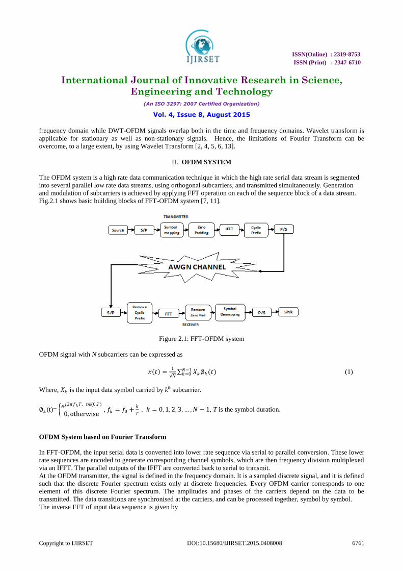
The OFDM system is a high rate data communication technique in which the high rate serial data stream is segmented
into several parallel low rate data streams, using orthogonal subcarriers, and transmitted simultaneously. Generation
and modulation of subcarriers is achieved by applying FFT operation on each of the sequence block of a data stream.
Fig.2.1 shows basic building blocks of FFT-OFDM system [7, 11].
Figure 2.1: FFT-OFDM system
OFDM signal with N subcarriers can be expressed as
𝑥 𝑡 =1
𝑁 𝑋𝑘∅𝑘(𝑡)𝑁−1
𝑘=0 (1)
Where, 𝑋𝑘 is the input data symbol carried by kth
subcarrier.
∅𝑘 (t)= 𝑒𝑗2𝜋𝑓𝑘𝑇, 𝑡∈(0,𝑇)
0, otherwise , 𝑓𝑘 = 𝑓0 +
𝑘
𝑇 , 𝑘 = 0, 1, 2, 3, … , 𝑁 − 1, T is the symbol duration.
OFDM System based on Fourier Transform
In FFT-OFDM, the input serial data is converted into lower rate sequence via serial to parallel conversion. These lower
rate sequences are encoded to generate corresponding channel symbols, which are then frequency division multiplexed
via an IFFT. The parallel outputs of the IFFT are converted back to serial to transmit.
At the OFDM transmitter, the signal is defined in the frequency domain. It is a sampled discrete signal, and it is defined
such that the discrete Fourier spectrum exists only at discrete frequencies. Every OFDM carrier corresponds to one
element of this discrete Fourier spectrum. The amplitudes and phases of the carriers depend on the data to be
transmitted. The data transitions are synchronised at the carriers, and can be processed together, symbol by symbol.
The inverse FFT of input data sequence is given by
ISSN(Online) : 2319-8753
ISSN (Print) : 2347-6710
International Journal of Innovative Research in Science,
Engineering and Technology (An ISO 3297: 2007 Certified Organization)
Vol. 4, Issue 8, August 2015
Copyright to IJIRSET DOI:10.15680/IJIRSET.2015.0408008 6762
𝐷𝑘 = d𝑛e−j(2πnk
N)
𝑁−1
𝑛=0 (2)
Where k=0,1,2,…,(N-1). Each dn is a complex number dn=an+jbn. (an,bn=±1 for QPSK, an,bn=±1, ±3 for 16QAM,..and
so on).This inverse transform generates orthogonal subcarriers and the input baseband signal is modulated over them.
Before transmission some guard bands like Cycle Prefix are added to the generated OFDM signal.
Cyclic Prefix (CP)
The dispersive nature of the channel tends to destroy the orthogonality between the subcarriers resulting in Inter
symbol Interference (ISI) and Inter Carrier Interference (ICI). To eliminate these problems cyclic prefix (CP) is
appended to the transmission stream. This CP consists of the copy of last few parts of the original samples. The length
of CP depends on length of the channel’s impulse response. At the receiver, the CP is discarded and remaining samples
are processed by the receiver. Although, the addition of CP mitigates ISI and ICI, it also reduces the data throughput
and precious bandwidth is wasted on repeated data [12, 15].
Peak-To-Average Power Ratio (PAPR)
PAPR is the ratio of the maximum power to the average power of a complex signal. Mathematically it is given as
𝑃𝐴𝑃𝑅 =max |𝑥 𝑛 |2
𝐸{ 𝑥 𝑛 2} (3)
Where 𝑚𝑎𝑥|𝑥 𝑛 |2 represents peak power and 𝐸{ 𝑥 𝑛 2 stands for average power of the complex signal 𝑥 𝑛 .When
N signals are added with the same phase, they produce a peak power that is N times of the average power. OFDM
signal consists of large number of independent subcarriers which may result in large PAPR when added coherently.
A large PAPR is detrimental because it increases the complexity of the system and reduces the efficiency of RF power
amplifier. The effect of PAPR is a serious problem in the transmitter. To avoid clipping of the transmitted waveform,
the power-amplifier at the transmitter frontend must have a wide linear range to include the peaks in the transmitted
waveform. Building power amplifiers with such wide linear ranges is very costly. Further, this also results in high
power consumption. The DAC’s and the ADC’s must also have a wide range to avoid clipping [2, 14].
As we know that Fourier transform is valid for stationary-ergodic signals only, it does not provide satisfactory results
when the communication signal is affected by Doppler, fading, acceleration, temperature etc, because in such scenarios
the signal does not remains stationary [13].
Wavelet Transform
A wavelet is a waveform of small duration that has an average value of zero. The basic idea of the using wavelet
transform is to represent any arbitrary function “s” as a superposition of a set of such wavelets or basis functions. These
basis functions or baby wavelets are obtained from a single prototype wavelet called the mother wavelet, by dilations or
contractions (scaling) and translations (shifts) [13]. The Discrete Wavelet Transform of a finite length signal s(n)
having N components is expressed by an N× N matrix. Wavelets have localization both in time and frequency domain,
and thus possess better orthogonality. The DWT of a signal can be evaluated by passing it through a series of filters.
In Fourier analysis, the signal is decomposed into a set of sinusoidal functions but in wavelet transform the signal is
first decomposed by a LPF and a HPF to down-sample the signal. We get approximation and detail coefficient from
g(n) and h(n) filters respectively, which are the wavelet’s half-band LPF and half-band HPF impulse responses.
ISSN(Online) : 2319-8753
ISSN (Print) : 2347-6710
International Journal of Innovative Research in Science,
Engineering and Technology (An ISO 3297: 2007 Certified Organization)
Vol. 4, Issue 8, August 2015
Copyright to IJIRSET DOI:10.15680/IJIRSET.2015.0408008 6763
ψ𝐿𝑃𝐹
𝑛 = 𝑠 𝑘 𝑔 2𝑛 − 𝑘 𝑘=+∞𝑘=−∞ (4)
ψ𝐻𝑃𝐹(𝑛) = 𝑠 𝑘 (2𝑛 − 𝑘)𝑘=+∞
𝑘=−∞ (5)
The DWT analyses the signal at different frequency bands with different resolutions by decomposing the signal into an
approximation containing coarse and detailed information [13]. The original signal s[n] is first applied to a half-band
high pass filter g[n] and a half-band low pass filter h[n]. A half-band low pass filter attenuates all frequencies that are
above half of the highest frequency, while a half-band high pass filter filters out all frequencies that are below half of
the highest frequency of the signal. The low pass filter halves the resolution, but leaves the scale unchanged. The signal
is then sampled by two since, according to the Nyquist’s rule; half of the number of samples is redundant [13].
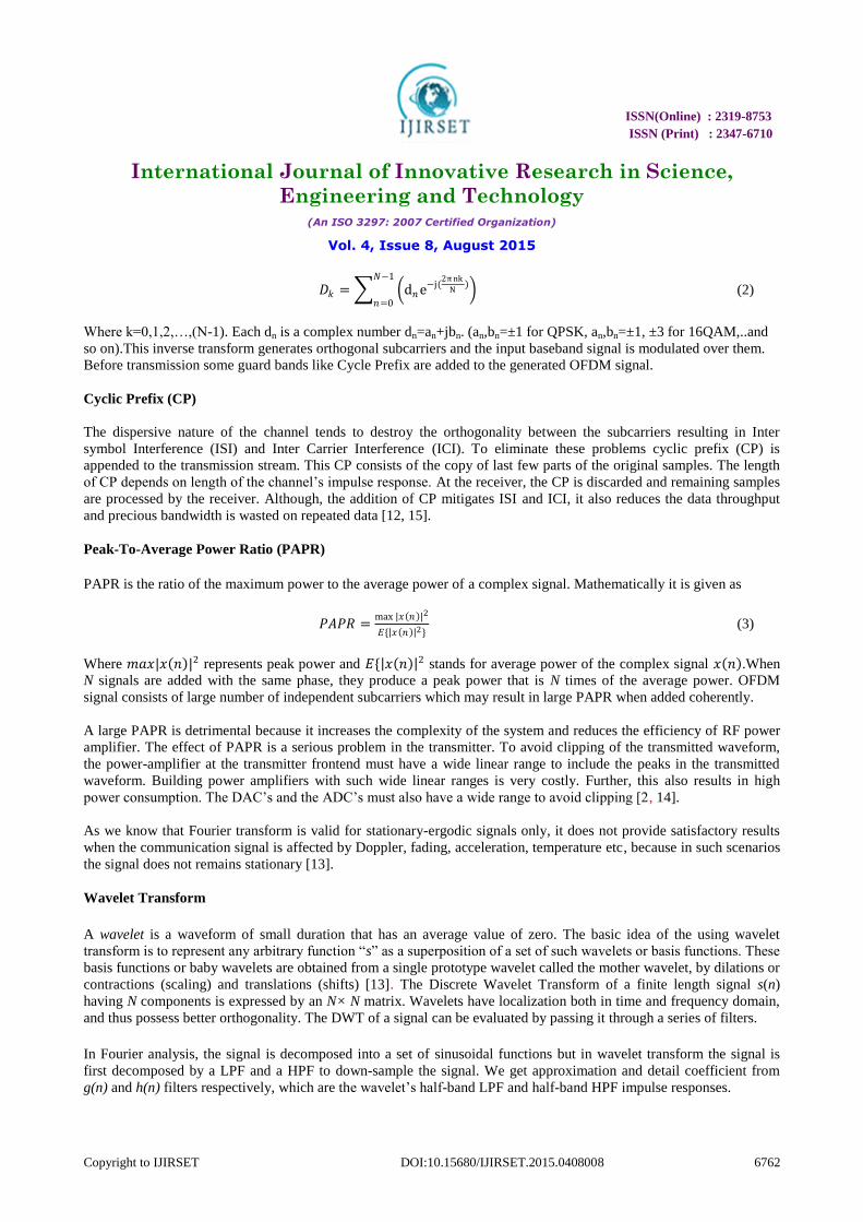
OFDM System based on Wavelet Transform
Wavelet based OFDM is very similar to the Fourier based OFDM. The only difference is that, the IFFT and FFT blocks
are substituted by IDWT and DWT blocks respectively. Fig.2.2 shows the block diagram of DWT based OFDM.
Figure 2.2: OFDM system with FFT and DWT
On the transmitter side, the input data is first applied to M-ary QAM modulator for data mapping, after mapping
process the data stream is converted into parallel data stream. Then it is applied to IDWT which produces one final
sequence of OFDM signal by up-sampling and filtering by the wavelet filters g(n) or h(n).
The output of the inverse discrete wavelet transform (IDWT) can be represented as:
𝑑 𝑘 = 𝐷𝑚𝑛 2
𝑚
2 𝛹(2𝑘𝑚 − 𝑛)∞
𝑛=0∞𝑚=0 (6)
Where 𝐷𝑚𝑛 are the wavelet coefficients and ψ(t) is the wavelet function with compression factor m and shifted n times
for each subcarrier and 0 ≤ k ≤ N − 1.
At the receiver side reverse operation of decomposition is performed. The DWT down-samples the received signal by
wavelet. The output of discrete wavelet transform (DWT) can be expressed as:
𝐷𝑚𝑛 = 𝑑 𝑘 2
𝑚
2 Ψ(2𝑘𝑚 − 𝑛)𝑁−1
𝑘=0 (7)
Multi-resolution analysis of wavelet theory allows to represent the wavelet and scaling functions by high and low pass
filters (HPF and LPF), respectively, with impulse responses (n) and 𝑔(n). Therefore, the wavelet transformation can
be easily implemented using discrete time filters
ISSN(Online) : 2319-8753
ISSN (Print) : 2347-6710
International Journal of Innovative Research in Science,
Engineering and Technology (An ISO 3297: 2007 Certified Organization)
Vol. 4, Issue 8, August 2015
Copyright to IJIRSET DOI:10.15680/IJIRSET.2015.0408008 6764
III. SIMULATIONS AND RESULTS
In this section the conventional OFDM and Wavelet based OFDM are modeled and simulated in Matlab®/Simulink
environment. Different channel conditions and modulation techniques are applied and their corresponding outputs are
compared. After successful design and simulation of OFDM systems the DWT-OFDM is utilized in DVB system for
terrestrial mode. For the simulation purposes, HAAR wavelet is used in DWT.
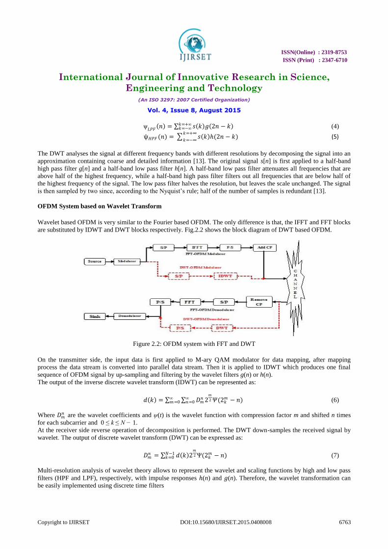
Figure 3.1: BER vs SNR for different modulation schemes for FFT and DWT OFDM
Figure 3.1 depicts that the BER performance of DWT-OFDM and FFT-OFDM systems. The Bit Error Rate
performance of a receiver is a figure of merit that eases the comparisons of various designs. Here we can see that for
8dB SNR the FFT-OFDM shows about 10-4
BER but for DWT-OFDM it is about 10-6
. From the figure, it is clear that
DWT-OFDM system performs better than FFT-OFDM. It can be seen that compared to DWT-OFDM system, the FFT-
OFDM system requires higher SNR to achieve the same BER improvement.
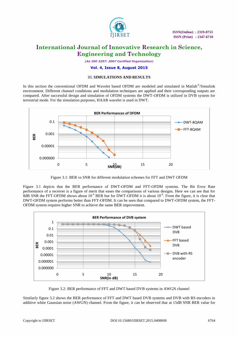
Figure 3.2: BER performance of FFT and DWT based DVB systems in AWGN channel
Similarly figure 3.2 shows the BER performance of FFT and DWT based DVB systems and DVB with RS encoders in
additive white Gaussian noise (AWGN) channel. From the figure, it can be observed that at 15dB SNR BER value for
0.000000
0.00001
0.001
0.1
0 5 10 15 20
BER
SNR(dB)
BER Performances of OFDM
DWT-8QAM
FFT-8QAM
0.000000
0.000001
0.00001
0.0001
0.001
0.01
0.1
1
0 5 10 15 20
BER
SNR(in dB)
BER Performance of DVB system
DWT based DVB
FFT based DVB
DVB with RS encoder
ISSN(Online) : 2319-8753
ISSN (Print) : 2347-6710
International Journal of Innovative Research in Science,
Engineering and Technology (An ISO 3297: 2007 Certified Organization)
Vol. 4, Issue 8, August 2015
Copyright to IJIRSET DOI:10.15680/IJIRSET.2015.0408008 6765
DWT based DVB is about 10-4
and for FFT based DVB is 10-1
. Thus BER performance of DWT based DVB is better
than FFT based DVB as well as with RS Encoder used in conventional DVB.
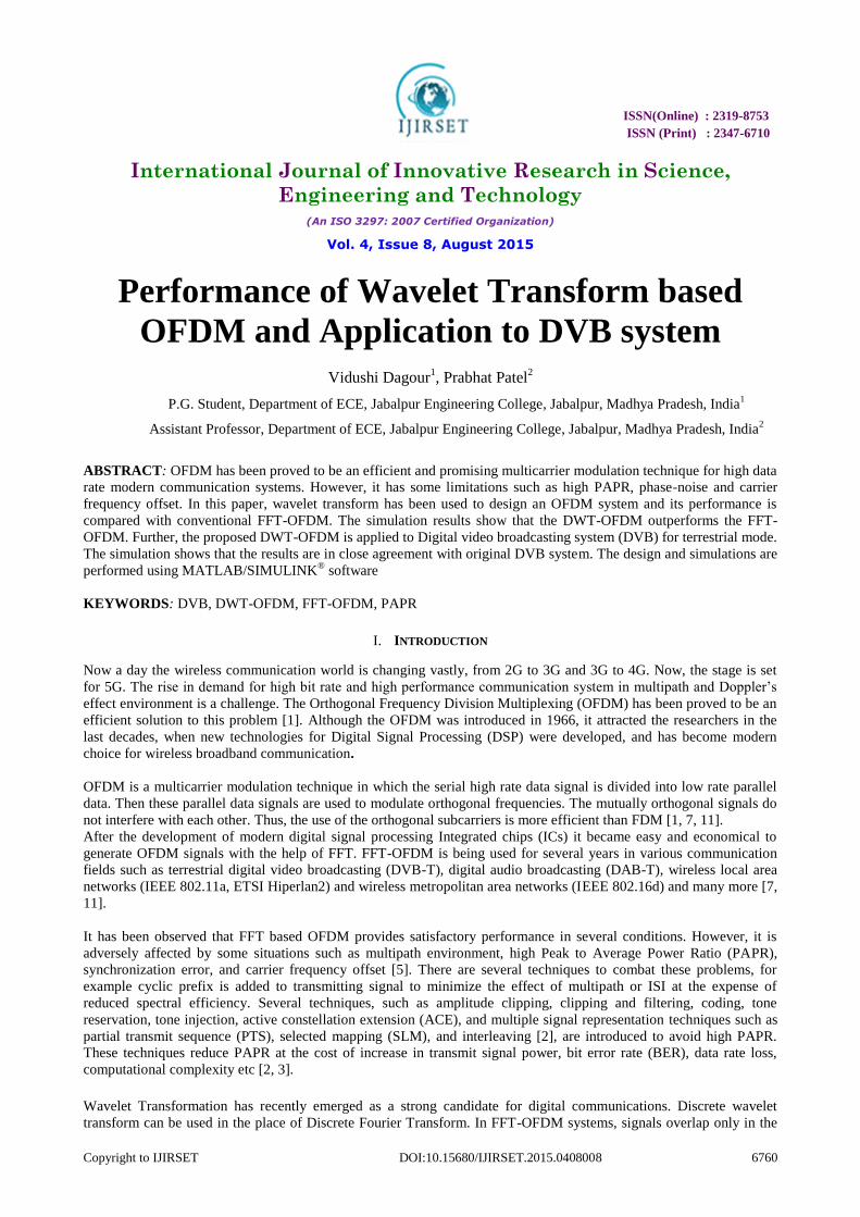
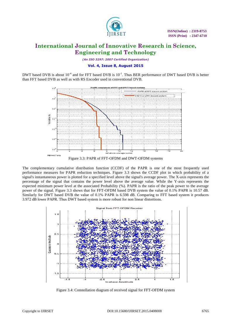
Figure 3.3: PAPR of FFT-OFDM and DWT-OFDM systems
The complementary cumulative distribution function (CCDF) of the PAPR is one of the most frequently used
performance measures for PAPR reduction techniques. Figure 3.3 shows the CCDF plot in which probability of a
signal's instantaneous power is plotted for a specified level above the signal's average power. The X-axis represents the
percentage of the signal that contains the power level above the average value. While the Y-axis represents the
expected minimum power level at the associated Probability (%). PAPR is the ratio of the peak power to the average
power of the signal. Figure 3.3 shows that for FFT-OFDM based DVB system the value of 0.1% PAPR is 10.57 dB.
Similarly for DWT based DVB the value of 0.1% PAPR is 6.598 dB. Comparing to FFT based system it produces
3.972 dB lower PAPR. Thus DWT based system is more robust for non linear distortions.
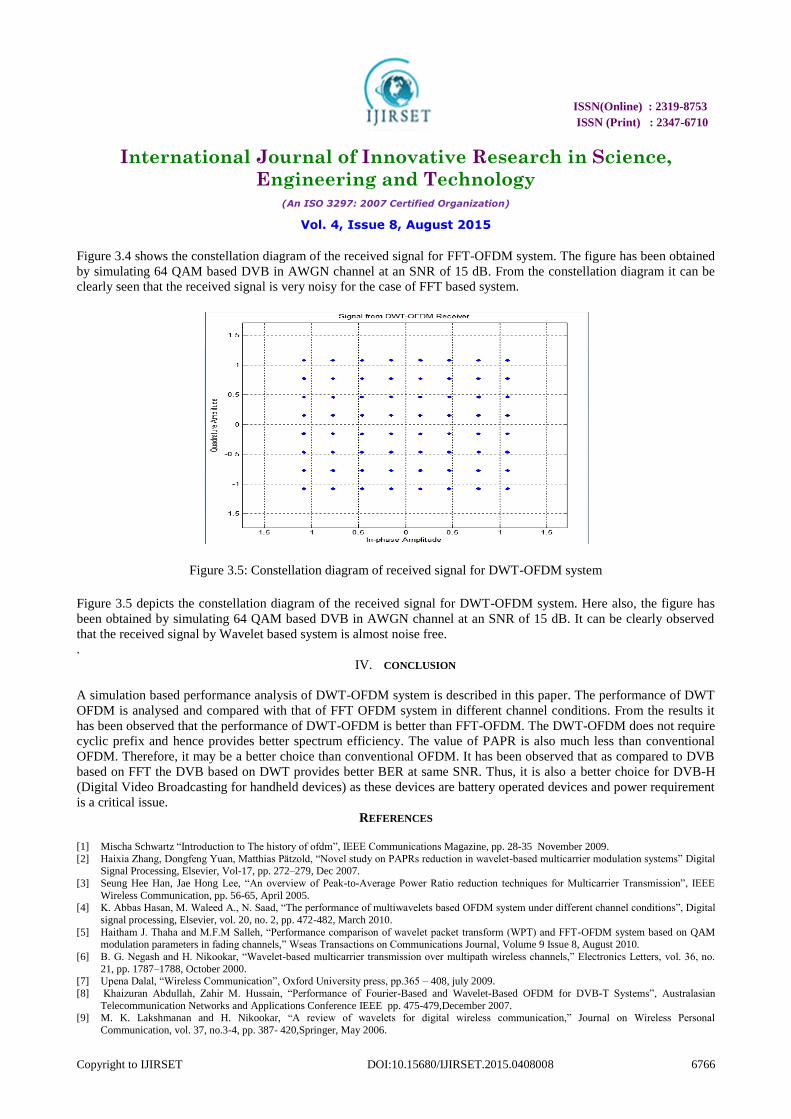
Figure 3.4: Constellation diagram of received signal for FFT-OFDM system
ISSN(Online) : 2319-8753
ISSN (Print) : 2347-6710
International Journal of Innovative Research in Science,
Engineering and Technology (An ISO 3297: 2007 Certified Organization)
Vol. 4, Issue 8, August 2015
Copyright to IJIRSET DOI:10.15680/IJIRSET.2015.0408008 6766
Figure 3.4 shows the constellation diagram of the received signal for FFT-OFDM system. The figure has been obtained
by simulating 64 QAM based DVB in AWGN channel at an SNR of 15 dB. From the constellation diagram it can be
clearly seen that the received signal is very noisy for the case of FFT based system.
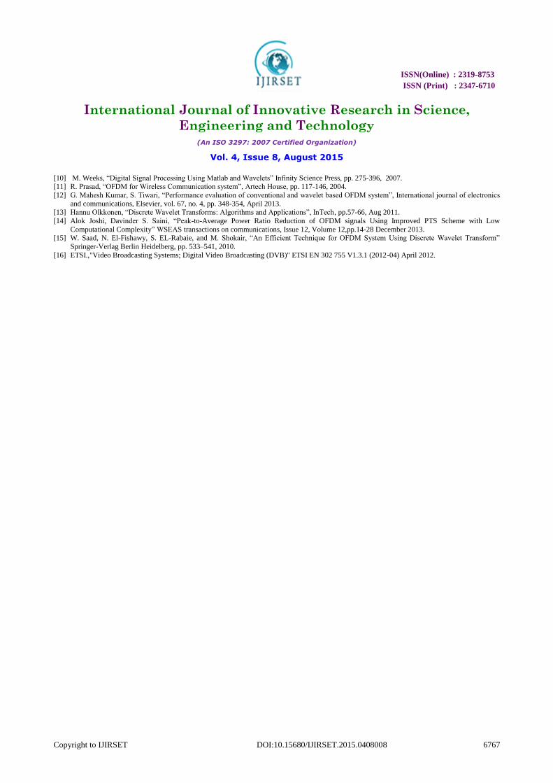
Figure 3.5: Constellation diagram of received signal for DWT-OFDM system
Figure 3.5 depicts the constellation diagram of the received signal for DWT-OFDM system. Here also, the figure has
been obtained by simulating 64 QAM based DVB in AWGN channel at an SNR of 15 dB. It can be clearly observed
that the received signal by Wavelet based system is almost noise free.
.
IV. CONCLUSION
A simulation based performance analysis of DWT-OFDM system is described in this paper. The performance of DWT
OFDM is analysed and compared with that of FFT OFDM system in different channel conditions. From the results it
has been observed that the performance of DWT-OFDM is better than FFT-OFDM. The DWT-OFDM does not require
cyclic prefix and hence provides better spectrum efficiency. The value of PAPR is also much less than conventional
OFDM. Therefore, it may be a better choice than conventional OFDM. It has been observed that as compared to DVB
based on FFT the DVB based on DWT provides better BER at same SNR. Thus, it is also a better choice for DVB-H
(Digital Video Broadcasting for handheld devices) as these devices are battery operated devices and power requirement
is a critical issue. REFERENCES
[1] Mischa Schwartz “Introduction to The history of ofdm”, IEEE Communications Magazine, pp. 28-35 November 2009.
[2] Haixia Zhang, Dongfeng Yuan, Matthias Pätzold, “Novel study on PAPRs reduction in wavelet-based multicarrier modulation systems” Digital Signal Processing, Elsevier, Vol-17, pp. 272–279, Dec 2007.
[3] Seung Hee Han, Jae Hong Lee, “An overview of Peak-to-Average Power Ratio reduction techniques for Multicarrier Transmission”, IEEE
Wireless Communication, pp. 56-65, April 2005. [4] K. Abbas Hasan, M. Waleed A., N. Saad, “The performance of multiwavelets based OFDM system under different channel conditions”, Digital
signal processing, Elsevier, vol. 20, no. 2, pp. 472-482, March 2010.
[5] Haitham J. Thaha and M.F.M Salleh, “Performance comparison of wavelet packet transform (WPT) and FFT-OFDM system based on QAM modulation parameters in fading channels,” Wseas Transactions on Communications Journal, Volume 9 Issue 8, August 2010.
[6] B. G. Negash and H. Nikookar, “Wavelet-based multicarrier transmission over multipath wireless channels,” Electronics Letters, vol. 36, no.
21, pp. 1787–1788, October 2000. [7] Upena Dalal, “Wireless Communication”, Oxford University press, pp.365 – 408, july 2009.
[8] Khaizuran Abdullah, Zahir M. Hussain, “Performance of Fourier-Based and Wavelet-Based OFDM for DVB-T Systems”, Australasian
Telecommunication Networks and Applications Conference IEEE pp. 475-479,December 2007. [9] M. K. Lakshmanan and H. Nikookar, “A review of wavelets for digital wireless communication,” Journal on Wireless Personal
Communication, vol. 37, no.3-4, pp. 387- 420,Springer, May 2006.
ISSN(Online) : 2319-8753
ISSN (Print) : 2347-6710
International Journal of Innovative Research in Science,
Engineering and Technology (An ISO 3297: 2007 Certified Organization)
Vol. 4, Issue 8, August 2015
Copyright to IJIRSET DOI:10.15680/IJIRSET.2015.0408008 6767
[10] M. Weeks, “Digital Signal Processing Using Matlab and Wavelets” Infinity Science Press, pp. 275-396, 2007. [11] R. Prasad, “OFDM for Wireless Communication system”, Artech House, pp. 117-146, 2004.
[12] G. Mahesh Kumar, S. Tiwari, “Performance evaluation of conventional and wavelet based OFDM system”, International journal of electronics
and communications, Elsevier, vol. 67, no. 4, pp. 348-354, April 2013. [13] Hannu Olkkonen, “Discrete Wavelet Transforms: Algorithms and Applications”, InTech, pp.57-66, Aug 2011.
[14] Alok Joshi, Davinder S. Saini, “Peak-to-Average Power Ratio Reduction of OFDM signals Using Improved PTS Scheme with Low
Computational Complexity” WSEAS transactions on communications, Issue 12, Volume 12,pp.14-28 December 2013. [15] W. Saad, N. El-Fishawy, S. EL-Rabaie, and M. Shokair, “An Efficient Technique for OFDM System Using Discrete Wavelet Transform”
Springer-Verlag Berlin Heidelberg, pp. 533–541, 2010.
[16] ETSI.,"Video Broadcasting Systems; Digital Video Broadcasting (DVB)" ETSI EN 302 755 V1.3.1 (2012-04) April 2012.