Embed Size (px)
Citation preview

ISSN (Print) : 2320 – 3765
ISSN (Online): 2278 – 8875
International Journal of Advanced Research in Electrical, Electronics and Instrumentation Engineering
Vol. 2, Issue 5, May 2013
Copyright to IJAREEIE www.ijareeie.com 1655
CONTROL OF THE PORTABLE FUEL
CELL CHARGER USING CUK
CONVERTER Tae-Hoon Kim
1, Nguyen Van Sang
1, and Woojin Choi
2
Student, Dept. of Electrical Engineering, Soongsil University, Seoul, Republic of Korea1
Associate professor, Dept. of Electrical Engineering, Soongsil University, Seoul, Republic of Korea2
ABSTRACT: As power consumption of portable electronic equipment rapidly increases; the need of chargers using
fuel cell which has higher energy density than that of secondary battery is raised. Most chargers developed so far are
mainly buck-type converters, however, if fuel cell is used the battery should be charged with an increased voltage level
through boost-type converter. In addition, unlike resistive load if batteries are controlled by general method, they
induce large ripple current and have bad influence on the efficiency and life cycle of the batteries. Therefore, the
selection of appropriate topology and control method is very important. In this paper a method of control for portable
fuel-cell charger using small PEM (Proton Exchange Membrane) fuel cell stack and Cuk converter is proposed and the
feasibility of it is verified through the experiments.
Keywords: PEM fuel cell, Battery Charger, Cuk Converter, Lithium-Polymer Battery, CC/CV mode charge
I.INTRODUCTION
As power consumption of portable electronic equipment rapidly increases, the need of chargers using fuel-cell which
has higher energy density than that of secondary battery is raised. In the future, tiny fuel cells can potentially replace
batteries in the next generation of portable electronics, such as laptop computers due to their high energy density and
longer operation time. A compact methanol cartridge can be developed into a fuel cell package that can power
electronic devices for three to five times longer than conventional batteries, though they can be accommodated in
containers of the same size and weight. Such systems can be recharged by simply refilling the fuel cartridges, and
existing research shows these fuel cells to be more environmentally friendly.
Most chargers developed so far are of On-Grid method and have decreasing voltage level by the buck-type converter
with a rectifier and a filter capacitor [1-2]. However, if fuel cell is used, the battery often need to be charged increasing
voltage level through boost-type converter due to the inherent low voltage characteristics of the fuel cell [3].It may be
possible to use a buck-type converter with transformer. However, since chargers used for portable electronic equipment
require miniaturization, a boost-type non-isolated converter can be selected as an appropriate topology. Unlike the pure
resistive load, since Lithium-Polymer batteries have a huge capacitance and a small resistance inside, when they are
charged by a non-isolated topology such as boost converter, higher value of the ripple current may flow through the
battery depending on the impedance of the battery and the output capacitor. It is also well known that the large ripple
current may cause a bad influence on the efficiency and life cycle of the batteries [4].
Cuk converter includes an inductor at the output like the buck converter, but unlike the boost converter, continuous
current flows in the output [5]. Also, Cuk Converter allows stepping up the voltage by varying the duty ratio of the
switch, thus it is suitable for the charge converter applications for the fuel cell.
In this paper control of the portable fuel cell charger using a fuel cell stack and a non-isolated Cuk converter is
described and frequency characteristics of the Cuk converter is analyzed by the state-space modeling technique
considering equivalent impedance of the battery. The battery is charged through the constant current mode (CCM) and
constant voltage mode (CVM) by the dual control loop, which controls both the converter output voltage through an
outer control loop and its input control through an inner control loop. The developed charger and its control algorithm
will be verified through CCM/CVM charge by the experiments, respectively.

ISSN (Print) : 2320 – 3765
ISSN (Online): 2278 – 8875
International Journal of Advanced Research in Electrical, Electronics and Instrumentation Engineering
Vol. 2, Issue 5, May 2013
Copyright to IJAREEIE www.ijareeie.com 1656
II. CHARACTERISTICS OF LITHIUM POLYMER BATTERY AND EQUIVALENT IMPEDANCE MODEL
A. Charging Method for the Lithium Polymer Battery
The general characteristic of a lithium polymer battery is as shown in Table I. The final discharge voltage is 3V per cell
and a maximum voltage after full charge is in between 4.1V to 4.3V per cell. Typically it is charged by using CC
(Constant Current) mode in the initial stage. When the battery voltage reaches to the full voltage, CV (Constant
Voltage) mode is then used [6]. In CC Mode, the battery is charged with 1C-rate permitted by the manufacturer and the
battery's voltage rises in this stage. When the terminal voltage of the battery reaches to the maximum level, the charger
changes its mode to CV mode and the charge current is exponentially decreased and the voltage maintains at a constant
value.
B. Equivalent Impedance Model of the Lithium Polymer Battery
To design a charge system for the lithium polymer battery, it is required to get an equivalent impedance model of the
Li-Polymer battery.
TABLE I
THE GENERAL CHARACTERISTICS OF THE LITHIUM-POLYMER BATTERY
Final
Discharge
Voltage
[V/cell]
Nominal
Voltage
[V/cell]
Maximum
Voltage at
Full Charge
[V/cell]
Charge
Method
3.0 3.6 4.1∼4.3 CC/CV
Fig. 1. CC/CV mode charge profile of the lithium-polymer battery
Fig. 2. Equivalent impedance model of the lithium-polymer battery
Many equivalent circuit models exist for the lithium polymer battery. However, in this study, the model was simply
developed as the modified Randle model by a series resistance, capacitance and an equivalent voltage source as shown
in Fig. 2 [7]. The initial voltage of the Cb is 0 and VDC represents an initial voltage of the lithium polymer battery. The
lithium polymer battery used in this study is AL3N5548135C-R-PCM by Exa Energy of which nominal capacity is
4000mAh, nominal voltage 11.1V, lower limit of the discharge voltage 9.0V, and higher limit of the charge voltage
12.6V.

ISSN (Print) : 2320 – 3765
ISSN (Online): 2278 – 8875
International Journal of Advanced Research in Electrical, Electronics and Instrumentation Engineering
Vol. 2, Issue 5, May 2013
Copyright to IJAREEIE www.ijareeie.com 1657
The capacitance Cb of the equivalence circuit model can be calculated from Q=CV equation. In this study, the
capacitance value of the battery was calculated as 4,000F as (1).
4.0 3600
4,00012.6 9.0
A sQCb F
V V V (1)
The series resistance Rb may be drawn from the time constant τ and capacity Cb, both from the real battery's CV Mode
current profile. In this study, the time constant was calculated as 1,834 seconds and the series resistance Rb as 460mΩ
as shown in (2).
1834
4604000
bb
R mC
(2)
Fig. 3. Charge current profile in CC/CV mode
III. MODELING OF THE CUK CONVERTER CONSIDERING BATTERY IMPEDANCE
In this study, a state space averaging method was employed for the modeling of the Cuk converter taking into account
the internal impedance of the battery. Fig. 4 shows the Cuk converter including equivalent impedance of the battery and
the state equations of the converter can be simply described in a matrix form as (3).
ˆ x Ax t Bu t y Cx t Eu t (3)
State variables at this time are the inductor current and capacitor voltage. Typically, the state equation for the Cuk
converter with pure resistive load has more than 4 variables [8-9], but there are 5 state variables in total when the
equivalence impedance of the battery is considered. Therefore, a state vector is equivalent to
1 1 2 2 T
bx t i t v t i t v t v t , input vector T
s DCu t v t v t , and output vector 0 T
sy t i t v t .
Fig. 4. Circuit diagram of the Cuk converter including battery impedance
ISSN (Print) : 2320 – 3765
ISSN (Online): 2278 – 8875
International Journal of Advanced Research in Electrical, Electronics and Instrumentation Engineering
Vol. 2, Issue 5, May 2013
Copyright to IJAREEIE www.ijareeie.com 1658
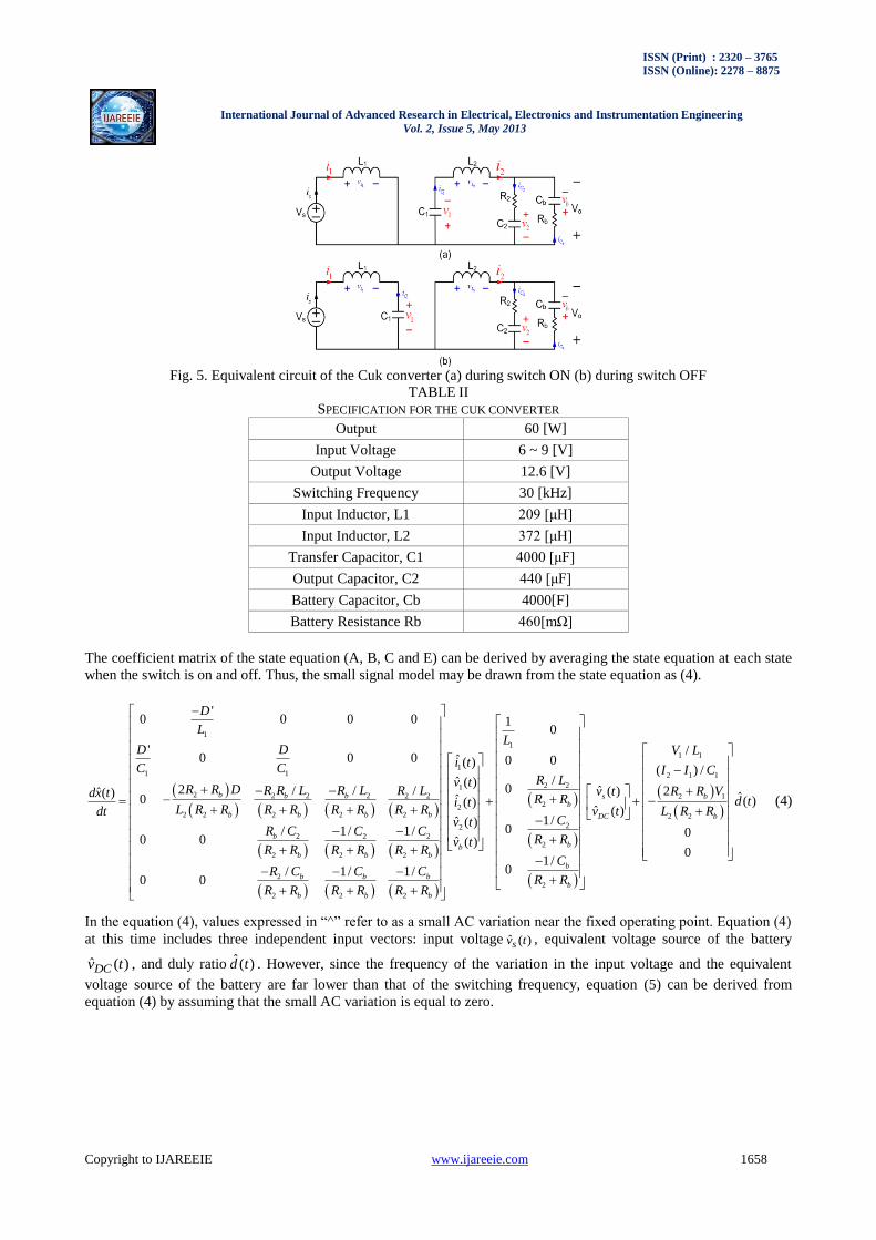
Fig. 5. Equivalent circuit of the Cuk converter (a) during switch ON (b) during switch OFF
TABLE II
SPECIFICATION FOR THE CUK CONVERTER
Output 60 [W]
Input Voltage 6 ~ 9 [V]
Output Voltage 12.6 [V]
Switching Frequency 30 [kHz]
Input Inductor, L1 209 [μH]
Input Inductor, L2 372 [μH]
Transfer Capacitor, C1 4000 [μF]
Output Capacitor, C2 440 [μF]
Battery Capacitor, Cb 4000[F]
Battery Resistance Rb 460[mΩ]
The coefficient matrix of the state equation (A, B, C and E) can be derived by averaging the state equation at each state
when the switch is on and off. Thus, the small signal model may be drawn from the state equation as (4).
1
11 1
12 2 2 2 2 2
22 2 2 2 2
2
2 2 2
2 2 2
2
2 2 2
'0 0 0 0
'0 0 0 ˆ ( )
ˆ ( )2 / / /ˆ( )
ˆ0 ( )
ˆ ( )/ 1/ 1/
0 0 ˆ
/ 1/ 1/0 0
b b b
b b b b
b
b b b
b b b
b b b
D
L
D Di tC Cv t
R R D R R L R L R Ldx ti t
L R R R R R R R Rdtv t
R C C C
R R R R R R
R C C C
R R R R R R
1
1 1
2 1 1
2 2
2 12
2 2
2
2
2
10
/0 0
( ) //
0 ˆ 2( ) ˆ( )ˆ ( )
1/0 0
( )0
1/0
bsb
DC b
bb
b
b
LV L
I I CR L
R R Vv tR R d t
v t L R RC
R Rv t
C
R R
(4)
In the equation (4), values expressed in “^” refer to as a small AC variation near the fixed operating point. Equation (4)
at this time includes three independent input vectors: input voltage ˆ ( )sv t , equivalent voltage source of the battery
ˆ ( )DCv t , and duly ratio ˆ( )d t . However, since the frequency of the variation in the input voltage and the equivalent
voltage source of the battery are far lower than that of the switching frequency, equation (5) can be derived from
equation (4) by assuming that the small AC variation is equal to zero.

ISSN (Print) : 2320 – 3765
ISSN (Online): 2278 – 8875
International Journal of Advanced Research in Electrical, Electronics and Instrumentation Engineering
Vol. 2, Issue 5, May 2013
Copyright to IJAREEIE www.ijareeie.com 1659
1
11 1
2 2 2 2 2 2
ˆ ( ) 0 2 2 2 2 2ˆ ( ) 0
2 2 2
2 2 2
2
2 2 2
'0 0 0 0
'0 0 0 ˆ ( )
ˆ2 / / /ˆ( )
0
/ 1 / 1 /0 0
/ 1 / 1 /0 0
s
DC
b b b
v t b b b bv t
b
b b b
b b b
b b b
D
L
D Di t
C Cv
R R D R R L R L R Ldx t
L R R R R R R R Rdt
R C C C
R R R R R R
R C C C
R R R R R R
1 1
2 1 1
1
2 1
2
2 2
2
/
( ) /( )
2 ˆˆ ( )( )
ˆ ( )0
ˆ ( )0
b
b
b
V L
I I Ct
R R Vd ti t
L R Rv t
v t
(5)
Equation (6) and (7) show the input current control transfer function, Gid and output voltage control transfer function,
Gvd, respectively. Both can be derived by Laplace transforming the state equation (5) and applying the parameter
values in the Table II.
4 3 24 3 2 1 0
5 4 3 25 4 3 2 1 0
ˆ ( )( )
ˆ( )
sid
i s a s a s a s a s aG s
d s c s c s c s c s c s c (6)
where,
3 8 11 13 94 3 2 1 028.433 10 , 1.38 10 , 1.89 10 , 6.65 10 , 2.09 10 a a a a a
3 6 9 11 85 4 3 2 1 01, 4.62 10 , 6.25 10 , 2 10 , 7.28 10 , 3.87 10 c c c c c c
4 3 20 4 3 2 1 0
5 4 3 25 4 3 2 1 0
ˆ ( )( )
ˆ( )
vd
v s b s b s b s b s bG s
d s c s c s c s c s c s c (7)
where, 7 9 12 94 3 2 1 014.89, 2.33 10 , 1.10 10 , 9.02 10 , 4.80 10 b b b b b
In order to verify the derived transfer functions in (6) and (7) AC sweep was performed on the model of the system by
PSIM and the resulting Bode plots were compared with the Bode plots drawn by the Matlab. As can be seen in Fig. 6
through Fig. 9 that the results for the current control transfer function and voltage control transfer function are well
matched thereby proving that the derived functions are correct.Fig. 10 shows the pole-zero maps for the current control
transfer function. A current control transfer function is a 5th order system that includes 5 poles and 4 zeroes, and has
one resonant frequency due to a pole pair.As seen in the Fig. 10, current control transfer function is the minimum-phase
system having all the poles and zeroes in the left-half plane and it has enough phase margin.Fig. 11 indicates a pole-
zero map of the voltage control transfer function. Like the current control transfer function, it is also a 5th order system
that includes 5 poles and 4 zeroes, but has 2 resonant frequencies due to a pair of poles and a pair of zeroes. Since it is a
non-minimum phase system with a pair of zeroes located in the right-half plane, it has no phase margin [10], [11].
Fig. 6. Bode plot of the current control transfer function (Matlab)

ISSN (Print) : 2320 – 3765
ISSN (Online): 2278 – 8875
International Journal of Advanced Research in Electrical, Electronics and Instrumentation Engineering
Vol. 2, Issue 5, May 2013
Copyright to IJAREEIE www.ijareeie.com 1660
Fig. 7. AC Sweep of the current control transfer function (PSIM)
Fig. 8. Bode plot of the voltage control transfer function (Matlab)
Fig. 9. AC Sweep of the voltage control transfer function (PSIM)

ISSN (Print) : 2320 – 3765
ISSN (Online): 2278 – 8875
International Journal of Advanced Research in Electrical, Electronics and Instrumentation Engineering
Vol. 2, Issue 5, May 2013
Copyright to IJAREEIE www.ijareeie.com 1661
IV. DESIGN OF THE CHARGER CONTROLLER
In this study, a double control loop is used for the charge controller. It consists of an inner loop for the current control
and outer loop for the voltage control as shown in Fig. 12. Such double control has an advantage that it is not required
to implement the controllers for each charge mode (CC and CV), respectively, thereby making the control algorithm
simple.
In the outer voltage control loop, reference voltage, nominal voltage of the battery pack, is compared to the voltage
feedback and creates current reference for the current control. At this time, the current reference is limited so that the
charge current does not exceed an allowed charge current value (1C-rate in this case). The reference current command
from the voltage controller is then compared to the feedback of the inductor current to generate the current error and it
is used for the current controller to adjust the duty of the switch through the comparator. At this time, a closed-loop
transfer function for the current control can be expressed by (8) and the closed-loop voltage transfer function that
includes current control can be expressed by (9) [12].
( ) 1/ i ic m id iT s G V G H (8)
1/
( )1
vc ic m vd vv
i
G G V G HT s
T (9)
Where, Gic is the current controller gain, Hi is the current feedback gain, 1/ mV is the comparator gain, Gvc is the
voltage controller gain and Hv is the voltage feedback gain.
A. Design of the Current Controller for CC Charge
Fig. 13 shows the design process of the inner loop for the input current control with Bode plot by using Matlab. As
shown in Fig. 12, since the transfer function for the input current is the minimum-phase system with enough phase
margins, a controller with 2-pole/1-zero was used to reduce the steady-state error by increasing the DC gain to enhance
the dynamic performance of the system by selecting a suitable crossover frequency.
The equation (10) and Table III show the transfer function of the inner control-loop and its parameter values. A
crossover frequency was selected at 6kHz, one-fifth of the switching frequency. It can be seen in the Fig. 9 that the DC
gain of the closed-loop transfer function has been largely increased, thereby reducing the steady-state error.
1 2
1 21 2 1 2
1 2
1( )
( ) 1( )
icsC R
G sC C
s C C R s RC C
(10)
Also, the slope of the closed-loop transfer function at crossover frequency is -20dB/dec. Upon compensation, the phase
margin is 60 degrees and the gain margin is more than 50dB, both of which indicate that the controller has been
designed appropriately.
B. Design of the Voltage Controller for CV Charge
As abovementioned, a voltage control transfer function is a non-minimum phase system having additional phase delays
due to the right-half-plane (RHP) zeroes. Accordingly, a crossover frequency is limited by a third of the RHP zero
frequency in order to guarantee the stable operation of the converter and thus the dynamic characteristics of the
converter becomes poor. However, it is not important because the dynamic characteristic of the converter is not a
critical factor for the battery charge application.
Therefore, 1-pole/1-zero controller is used for the voltage controller to increase the DC gain of the voltage control loop
in the low frequency regime since it has a pole at the origin. The equation (11) and Table IV are the transfer function
and parameter values of the voltage controller. Fig. 9 shows the design process of the outer loop for the output voltage
control with Bode plot by using Matlab. The crossover frequency of the closed loop transfer function is 15Hz, one-
sixths of the frequency of the left half plane zero. As can be seen in the Fig. 14, the phase margin and gain margin of
the closed loop transfer function is 80 degree and 30dB respectively, both of which indicate that the controller has been
designed to guarantee the stable operation of the charge system.
1 2 1 1( ) 1 / vcG s sC R sC R (11)

ISSN (Print) : 2320 – 3765
ISSN (Online): 2278 – 8875
International Journal of Advanced Research in Electrical, Electronics and Instrumentation Engineering
Vol. 2, Issue 5, May 2013
Copyright to IJAREEIE www.ijareeie.com 1662
TABLE III
PARAMETERS OF THE 2P-1Z CONTROLLER FOR THE
INNER CONTROL LOOP
R1 10 [kΩ]
R2 43.29 [kΩ]
C1 2.29 [μF]
C2 0.18 [nF]
TABLE IV
PARAMETERS OF THE 1P-1Z CONTROLLER FOR THE
OUTER VOLTAGE CONTROL LOOP
R1 10 [kΩ]
R2 500 [Ω]
C1 0.2 [μF]
Fig. 10. Pole-zero map of the current control transfer function

ISSN (Print) : 2320 – 3765
ISSN (Online): 2278 – 8875
International Journal of Advanced Research in Electrical, Electronics and Instrumentation Engineering
Vol. 2, Issue 5, May 2013
Copyright to IJAREEIE www.ijareeie.com 1663
Fig. 11. Pole-zero map of the voltage control transfer function
Fig. 12. Block diagram of the dual loop charge controller

ISSN (Print) : 2320 – 3765
ISSN (Online): 2278 – 8875
International Journal of Advanced Research in Electrical, Electronics and Instrumentation Engineering
Vol. 2, Issue 5, May 2013
Copyright to IJAREEIE www.ijareeie.com 1664
Fig. 13. Design of the input current controller
Fig. 14. Design of the voltage controller
ISSN (Print) : 2320 – 3765
ISSN (Online): 2278 – 8875
International Journal of Advanced Research in Electrical, Electronics and Instrumentation Engineering
Vol. 2, Issue 5, May 2013
Copyright to IJAREEIE www.ijareeie.com 1665
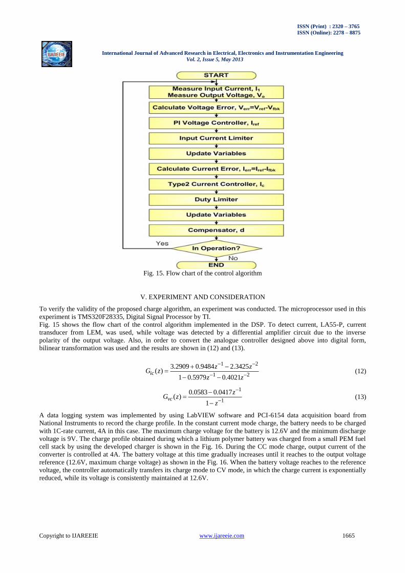
Fig. 15. Flow chart of the control algorithm
V. EXPERIMENT AND CONSIDERATION
To verify the validity of the proposed charge algorithm, an experiment was conducted. The microprocessor used in this
experiment is TMS320F28335, Digital Signal Processor by TI.
Fig. 15 shows the flow chart of the control algorithm implemented in the DSP. To detect current, LA55-P, current
transducer from LEM, was used, while voltage was detected by a differential amplifier circuit due to the inverse
polarity of the output voltage. Also, in order to convert the analogue controller designed above into digital form,
bilinear transformation was used and the results are shown in (12) and (13).
1 2
1 2
3.2909 0.9484 2.3425( )
1 0.5979 0.4021
ic
z zG z
z z (12)
1
1
0.0583 0.0417( )
1
vc
zG z
z (13)
A data logging system was implemented by using LabVIEW software and PCI-6154 data acquisition board from
National Instruments to record the charge profile. In the constant current mode charge, the battery needs to be charged
with 1C-rate current, 4A in this case. The maximum charge voltage for the battery is 12.6V and the minimum discharge
voltage is 9V. The charge profile obtained during which a lithium polymer battery was charged from a small PEM fuel
cell stack by using the developed charger is shown in the Fig. 16. During the CC mode charge, output current of the
converter is controlled at 4A. The battery voltage at this time gradually increases until it reaches to the output voltage
reference (12.6V, maximum charge voltage) as shown in the Fig. 16. When the battery voltage reaches to the reference
voltage, the controller automatically transfers its charge mode to CV mode, in which the charge current is exponentially
reduced, while its voltage is consistently maintained at 12.6V.

ISSN (Print) : 2320 – 3765
ISSN (Online): 2278 – 8875
International Journal of Advanced Research in Electrical, Electronics and Instrumentation Engineering
Vol. 2, Issue 5, May 2013
Copyright to IJAREEIE www.ijareeie.com 1666
Fig. 16. Experimental results of the charge profile of the lithium-polymer battery using Cuk converter
Fig. 17. Current waveform during CC mode (a) input current (b) battery current
As was seen in the experimental results, CC and CV mode charge was performed successfully, thereby verifying the
stable operation of the charger and its control algorithm. Fig. 17 shows the waveforms of the input current to the
converter from the PEM fuel cell stack and the charge current to the battery in the CC mode, respectively. As shown in
the Figure 17, input current has 30 kHz switching ripple and the magnitude of the battery current ripple is
approximately 100mA, which is less than 3% ripple ratio, and it satisfies the current ripple requirements for the battery.
VI. CONCLUSION
In this study, a portable fuel cell charger was designed by using a small PEM fuel cell stack and a Cuk converter. To
charge the battery in CC/CV modes, current and voltage were controlled by a single control loop, simplifying the
software, and its feasibility was verified through the experiments. The developed charger can be used for the boost
charge application using fuel cells.

ISSN (Print) : 2320 – 3765
ISSN (Online): 2278 – 8875
International Journal of Advanced Research in Electrical, Electronics and Instrumentation Engineering
Vol. 2, Issue 5, May 2013
Copyright to IJAREEIE www.ijareeie.com 1667
ACKNOWLEDGMENT
This work was supported by the Human Resources Development program No.20124030200070 of the Korea Institute
of Energy Technology Evaluation and Planning(KETEP) grant funded by the Korea government Ministry of Trade,
Industry and Energy.
REFERENCES
[1] Chen J.-J., Yang F.-C., Lai C.-C., Hwang Y.-S., and Lee R.-G., "A High-Efficiency Multimode Li–Ion Battery Charger With Variable
Current Source and Controlling Previous-Stage Supply Voltage," IEEE Trans. Ind. Appl., Vol. 56, No. 7, pp. 2469~2478, 2009
[2] Yang Bo, Lee F.C., Zhang A.J., and Huang G., "LLC Resonant Converter for Front End DC/DC Conversion," in Proc. APEC 2002, Vol. 2,
pp. 1108~1112, 2002,
[3] Lee K., Cho Y., Park J., Kim Y., Kim J. and Chang N., "A Fuel-Cell-Battery Hybrid Platform for Portable Embedded Systems," in Proc.
17th IFAC, pp. 2188~2193,2008
[4] Sang-hwaJung, Young-jinWu, Nam-in Kim, "Analogue-digital Switching Combination Low Ripple-High efficiency Li-Ion Battery
Charger," 2001 Korea Electric Academic Conference Paper, pp. 2531~2533, 2001
[5] W. Gu, "Small signal modeling for current mode controlled Cuk and SEPIC converters," in Proc. APEC 2005, Vol. 2, March, 2005, pp.
906~910.
[6] Dongyuk Mechatronics Lab, Secondary Power Cell and Battery Charging Device Deisgn, International Techno Infomration Lab, 2005.
[7] Hwa-young Won, Soo-yongChae, Sun-chanHong, "Interpretation of Charging and Discharging System for Lithium Cells by Average State
Space," Electric Power Conference Paper, 14th Edition, 5th Version, pp. 387~396, 2009.
[8] Erickson Warren, and MaksimovicDragan, Fundamentals of Power Electronics 2nd ed., Kluwer Academic, 2001.
[9] RiawanD.C., and NayarC.V., "Analysis and design of a solar charge controller using cuk converter," in Proc. AUPEC 2007, pp. 1~6, 2007.
[10] KittipeerachonK., and BunlaksananusornC., "Feedback compensation design for switched mode power supplies with a right-half plane
(RHP) zero," in Proc. PEMD 2004, Vol. 1, pp. 236~241, 2004.
[11] Diaz D., Garcia O., Oliver J.A., Alou P., and CobosJ.A., "Analysis and design considerations for the right half -plane zero cancellation on a
boost derived dc/dc converter," in Proc. PESC 2008, pp. 3825~3828, 2008
[12] Huang X., Wang X., NergaardT., Lai J.,Xu X. and Zhu L., "Parasitic ringing and design issues of digitally controlled high power
interleaved boost converters," IEEE Trans. Power Electron., Vol. 19, No. 5, pp. 1341~1352, 2004.
[13] Han-ulPark, Eun-sooKim, Su-sukKim, Joong-ho Song, "Insulation Inverse-SPIC's Modeling and Control Characteristics," Electric Power Conference Paper, 13th Edition, 1st Version, pp. 1~8, 2008.
BIOGRAPHY
Tae-Hoon Kim was born in Seoul, Republic of Korea,in 1983. He received his B.S. and M.S. in ElectricalEngineering
from Soongsil University, Republic ofKorea, in 2009 and 2011, respectively. His currentresearch interests
includeswitching power converters,power electronic systems, BMS, battery systems, andEV/PHEV charging systems.
He is currently a Researcherat the Electronic System R&D Center of theKorea Automotive Technology Institute.
NguyenVan Sang was born in Hanoi,Vietnam, in 1985. He received his B.S. inElectrical Engineering fromHanoi
Universityof Technology, Hanoi, Vietnam, in 2008. Heis currently working toward his M.S. atSoongsil University,
Seoul, Republic ofKorea. His current research interests includebattery chargers and dc–dc converters.
Woojin Choi was born in Seoul, Republic of Korea, in1967. He received his B.S. and M.S. inElectrical
Engineeringfrom Soongsil University, Republic of Korea,in 1990 and 1995, respectively. He received his Ph.D.in
Electrical Engineering from Texas A&M University,USA, in 2004. From 1995 to 1998, he was with DaewooHeavy
Industries as a Research Engineer. His currentresearch interests include the modeling and controlof electrochemical
energy sources such as fuel cells,batteries and supercapacitors, power conditioning technologies in renewableenergy
systems, and dc-dc converters for fuel cells and hybrid electric vehicles.