Embed Size (px)
Citation preview
8/14/2019 Vol 2. 1 jan-feb
http://slidepdf.com/reader/full/vol-2-1-jan-feb 1/22
1
In this issue PageFrom the HCR Desk…………………..1In The Land Down Under…..………2-6From the Shed & Crossword………..7Tool Time……………………………….8Inertia and the Center of Gravity &Good News For Builders……..9,10&11Stress Rise…………………………11-12Building My First Car (Part 2)…..13-21EDITORIAL……………………………..22
HORSE HORSE HORSE HORSELESS CARRIAGE REPLICA NEWSLETTER LESS CARRIAGE REPLICA NEWSLETTER LESS CARRIAGE REPLICA NEWSLETTER LESS CARRIAGE REPLICA NEWSLETTERPublished by Lee Thevenet
Volume 2 Issue 1 January/February 2010
A Publication dedicated to the reporting of news, events, articles, photos, itemsfor sale, etc, having to do with replica horseless carriages.
Newsletter published six times a year and special issues when needed.
From the HCR News DeskFrom the HCR News DeskFrom the HCR News DeskFrom the HCR News Desk
Hello everyone in HCR Land, I would like to wish all of our readers, HappyNew Year! I hope all of you had a joyful Christmas and have all your new shoptools ready to build that special HCR for this year’s parade and show season.
I would like to start off the yearwith an article from a former contributor tothe respected Newsletter of publisher andeditor, Everett Moore. Mr. Moore featuredarticles by him in two Newsletters. His FordQuad HCR, was covered very completely inthe E&W publications but this extraordinarybuilder has built two other carriagesbesides his Quad.
He probably needs nointroduction, besides his writings in Mr. Moore’s E&W issues, most of you havealready seen his posts on the Yahoo HCR Forum. His name is Stu Martyn ofAustralia and would like to share some information of his builds, including hisother work and interests. His writings have appeared in issues of the AustralianModel Engineering. I have been granted permission to run the articles as theyappeared in the magazines. They will appear in the next 2-3 issues of HCRNews……Enjoy!

8/14/2019 Vol 2. 1 jan-feb
http://slidepdf.com/reader/full/vol-2-1-jan-feb 2/22
2
InInInIn The Land Down Under The Land Down Under The Land Down Under The Land Down Under
ByByByByStu MartynStu MartynStu MartynStu Martyn
I have always been interested in mechanical motions and it seems thatthe majority of the more interesting ones were developed during the steam era.Over the past few years I have built working steam models of just abouteverything steam powered known to man. This includes steam locos, steamtractors, steam turbines, steam launch engines, the weird engines such as theRectilinear engine, the Coombers rotary, walking beam engines etc.
This is all very well but then I decided that I needed something bigenough for me to sit on and operate rather than watch these toys run around onthe shed floor. I then built a five inch gauge loco but became impatient with theother loco operators dictating on when I could go, or stop.
Next step was to build a half size steam tractor, the Wallis & Stevens,which gave me more freedom as to where it could be run. I eventually sold itbecause of its weight which posed problems transporting it to and fro to my localsteam club.
In 2004 I built from scratch, and generally to my own design, a LPG fired7/8 size steam car based on the 1904 C4 Stanley steamer. The laws in Australiarelating to the construction and building of steam boilers are very strict and if onebuilds a boiler similar to that which the Stanley twins used originally then it wouldlead to a never ending bureaucratic bungling, to say the least, to get it passed -notto mention the associated costs to get the boiler accepted.

8/14/2019 Vol 2. 1 jan-feb
http://slidepdf.com/reader/full/vol-2-1-jan-feb 3/22
3
We are fortunate, in Australia, to have our own recognized boiler codefor Model Engineers but this code puts its own restrictions such as the max boilerpressure which is limited to only 100 psi (700Kpa). Bearing in mind that theStanley’s used much higher boiler pressures than 100 psi, my car lacks grunt as itonly develops about 1.5 HP. It runs free and well as long as one keeps the speeddown to about 15 mph to conserve steam and it won't climb a steep hill withoutprotest!
The Model Eng boiler code also limits the max amount of water that theboiler can contain as well as its max. dia which is 8 inches. To get enough steamcapacity I used a loop hole in the code and have used two boilers in parallel.Using two boilers in parallel creates another problem and that is how to make twoboilers work successfully without having unlit gas pool under the car if one mainburner fails to ignite. I elected to use a system where the main burners are ignited
by separate pilot lights and the whole system is monitored by heat sensitivethermocouples so that if either burner fails to ignite the whole show shuts downautomatically. Brakes are of the drum type using motor bike internals.
My next venture (2007) was to build my version of Henry Ford'sQuadricycle, including the engine - have a look at 'SmallCarPlans.com’s web site,there is a brief glimpse of how it all came together. I tried band brakes on the quadand have to report that they are about as much use in stopping the vehicle ashaving a pair of pockets in one's underwear!
8/14/2019 Vol 2. 1 jan-feb
http://slidepdf.com/reader/full/vol-2-1-jan-feb 4/22
4
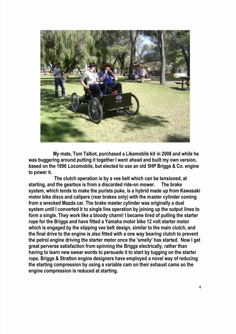
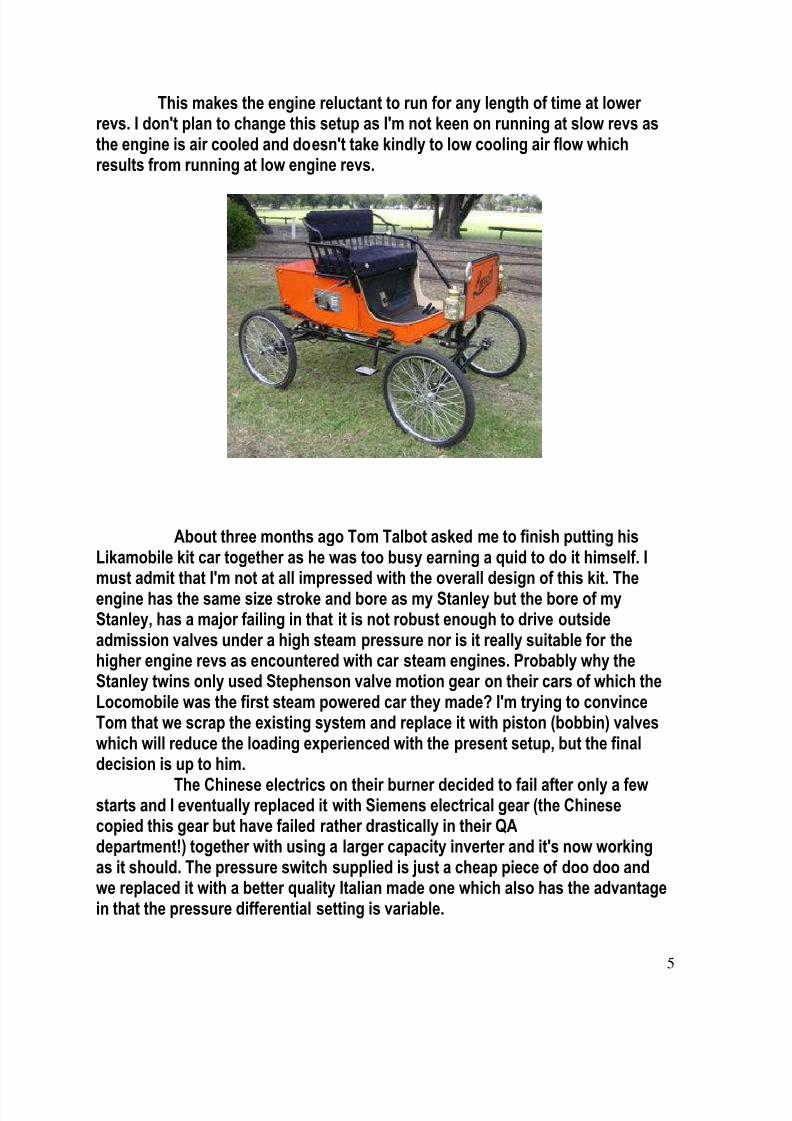
My mate, Tom Talbot, purchased a Likamobile kit in 2008 and while hewas buggering around putting it together I went ahead and built my own version,based on the 1896 Locomobile, but elected to use an old 5HP Briggs & Co. engineto power it.
The clutch operation is by a vee belt which can be tensioned, atstarting, and the gearbox is from a discarded ride-on mower. The brakesystem, which tends to make the purists puke, is a hybrid made up from Kawasakimotor bike discs and calipers (rear brakes only) with the master cylinder comingfrom a wrecked Mazda car. The brake master cylinder was originally a dualsystem until I converted it to single line operation by joining up the output lines toform a single. They work like a bloody charm! I became tired of pulling the starterrope for the Briggs and have fitted a Yamaha motor bike 12 volt starter motorwhich is engaged by the slipping vee belt design, similar to the main clutch, and
the final drive to the engine is also fitted with a one way bearing clutch to preventthe petrol engine driving the starter motor once the 'smelly' has started. Now I getgreat perverse satisfaction from spinning the Briggs electrically, rather thanhaving to learn new swear words to persuade it to start by tugging on the starterrope. Briggs & Stratton engine designers have employed a novel way of reducingthe starting compression by using a variable cam on their exhaust cams so theengine compression is reduced at starting.
8/14/2019 Vol 2. 1 jan-feb
http://slidepdf.com/reader/full/vol-2-1-jan-feb 5/22
5
This makes the engine reluctant to run for any length of time at lowerrevs. I don't plan to change this setup as I'm not keen on running at slow revs asthe engine is air cooled and doesn't take kindly to low cooling air flow whichresults from running at low engine revs.
About three months ago Tom Talbot asked me to finish putting hisLikamobile kit car together as he was too busy earning a quid to do it himself. Imust admit that I'm not at all impressed with the overall design of this kit. Theengine has the same size stroke and bore as my Stanley but the bore of myStanley, has a major failing in that it is not robust enough to drive outsideadmission valves under a high steam pressure nor is it really suitable for thehigher engine revs as encountered with car steam engines. Probably why theStanley twins only used Stephenson valve motion gear on their cars of which theLocomobile was the first steam powered car they made? I'm trying to convinceTom that we scrap the existing system and replace it with piston (bobbin) valveswhich will reduce the loading experienced with the present setup, but the finaldecision is up to him.
The Chinese electrics on their burner decided to fail after only a fewstarts and I eventually replaced it with Siemens electrical gear (the Chinesecopied this gear but have failed rather drastically in their QAdepartment!) together with using a larger capacity inverter and it's now workingas it should. The pressure switch supplied is just a cheap piece of doo doo andwe replaced it with a better quality Italian made one which also has the advantagein that the pressure differential setting is variable.
8/14/2019 Vol 2. 1 jan-feb
http://slidepdf.com/reader/full/vol-2-1-jan-feb 6/22
6
The sight glass is a bit of a joke as it is too small for the job, isincorrectly mounted unless one needs to see if the bottom part of the boiler hasany water in it and to compound the hassles it is mounted in such a position thatmakes it impossible to view without removing panels or the judicial use of mirrorsto even be able to see it!The front steering tie rod is not sturdy enough to do the job and the use of aScotch link is doubtful as far as strength is concerned.
I make up my own differentials by using modern diff guts. The originalcrown wheel can be easily removed and replaced with a sprocket. By making upbearing retaining cups for the diff bearings (usually tapered bearings pre-tensioned which I discard and replace with standard sealed ball bearings) I find Ican insert the assembly into the rear axle housing. I reuse the splined ends of theoriginal axle and weld an extension piece of axle to give me any desired trackwidth. The gear type diff as supplied with the kit is prehistoric in design (to say
the least!) and a real bugger to seal up to stop the oil dripping out. By using mysetup I leave the diff guts dry, but with the occasional drop of oil handapplied (modern diffs are made from substantial hardened material and I don'texpect mine to wear out during my lifetime!) and the axle outrigger bearings areheld in position by circlips at the axle tube ends. The outrigger bearing comes upagainst a shoulder machined on the axle shaft. This means that I can pull up thenuts on the wheel hubs without affecting the tension on the outrigger bearingswhich is a bit different from the Likamobile idea of having the drive wheel hubloose on the shaft. No wonder that the early UK car builders, unlike the blokes inthe USA, (Doble, White and Stanley), never ever made a successful productionsteam car!Cheers,Stu Martyn
Well builders, did you enjoy Stu’s article? That one was written especiallyfor this issue of the HCR News. Like I said earlier, the HCR News will feature moreof Stu’s articles, especially more on his Stanley & other beautiful creations in thecoming months thanks to the courtesy of Dave Proctor, Editor of the Australian
Model Engineering Magazine.
My thanks to Dave for allowing me to re-publish Stu’s accomplishments,It sure cut down my workload for awhile….:)
Lee Thevenet
8/14/2019 Vol 2. 1 jan-feb
http://slidepdf.com/reader/full/vol-2-1-jan-feb 7/22
7
From The ShedFrom The ShedFrom The ShedFrom The Shed & Crossword& Crossword& Crossword& CrosswordByByByBy
LeeLeeLeeLee
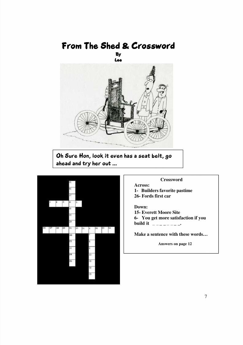
Oh Sure Hon, look it even has a seat belt, goahead and try her out …
CrosswordAcross:1- Builders favorite pastime26- Fords first car
Down:15- Everett Moore Site6- You get more satisfaction if youbuild it _ _ _ _ _ _ _ _.
Make a sentence with these words…
Answers on page 12
8/14/2019 Vol 2. 1 jan-feb
http://slidepdf.com/reader/full/vol-2-1-jan-feb 8/22
8
Tool TimeTool TimeTool TimeTool TimeByByByBy
Lee ThevenetLee ThevenetLee ThevenetLee Thevenet
How many times have you ever wanted to lay out two parallel linesclose to each other or lay out a line parallel to the edge of a piece of material youare building with?
There is a tool, that is fairly inexpensive at your local Harbor Freight
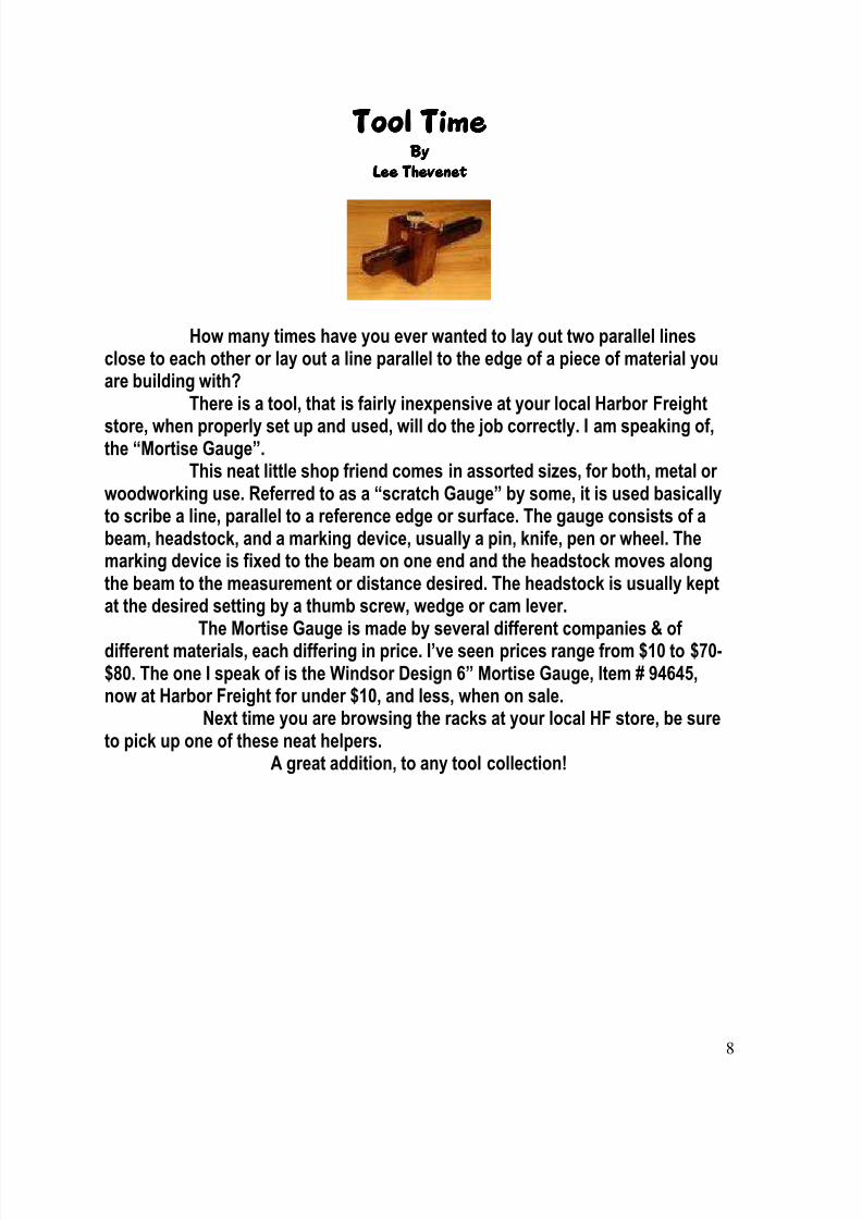
store, when properly set up and used, will do the job correctly. I am speaking of,the “Mortise Gauge”.This neat little shop friend comes in assorted sizes, for both, metal or
woodworking use. Referred to as a “scratch Gauge” by some, it is used basicallyto scribe a line, parallel to a reference edge or surface. The gauge consists of abeam, headstock, and a marking device, usually a pin, knife, pen or wheel. Themarking device is fixed to the beam on one end and the headstock moves alongthe beam to the measurement or distance desired. The headstock is usually keptat the desired setting by a thumb screw, wedge or cam lever.
The Mortise Gauge is made by several different companies & ofdifferent materials, each differing in price. I’ve seen prices range from $10 to $70-$80. The one I speak of is the Windsor Design 6” Mortise Gauge, Item # 94645,now at Harbor Freight for under $10, and less, when on sale.
Next time you are browsing the racks at your local HF store, be sureto pick up one of these neat helpers.
A great addition, to any tool collection!
8/14/2019 Vol 2. 1 jan-feb
http://slidepdf.com/reader/full/vol-2-1-jan-feb 9/22
9
INERTIA AND THE CENTER OF GRAVITY By
Bob Kapela
A high percentage of builders, especially “first timers”, elect to build ageneric replica, using Jimmy Wood’s fine plans, or others, instead of tacklingthe more difficult true replicas of early cars. After the enjoyable experience ofbuilding and driving their first machine, they often decide to build a second,more challenging one, a true replica.
When building your first machine, it is common, and there is nothingwrong, with using a little “license” and deviating from the design toincorporate your own ideas, especially on the body style and finish. The manyvariants of the Jimmy Wood’s design attest to this. Most of my machines haveroots in the design from the original plans. Just be sure you stay within provensafety guidelines.
This article will deal primarily with the “Center of Gravity” and “Inertia”.You do not want to challenge the basic laws of these when deviating fromplans. The Jimmy Wood’s design has a fairly high center of gravity. When builtand driven as designed, it is fine. However, if someone builds one that can go25 mph. or installs a wider seat, the combination can challenge the laws ofgravity and inertia during sudden or sharp turns.
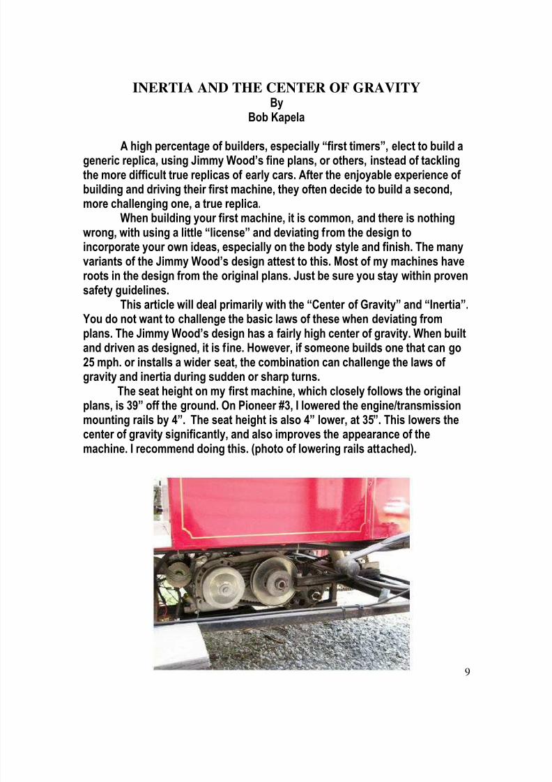
The seat height on my first machine, which closely follows the original
plans, is 39” off the ground. On Pioneer #3, I lowered the engine/transmissionmounting rails by 4”. The seat height is also 4” lower, at 35”. This lowers thecenter of gravity significantly, and also improves the appearance of themachine. I recommend doing this. (photo of lowering rails attached).

8/14/2019 Vol 2. 1 jan-feb
http://slidepdf.com/reader/full/vol-2-1-jan-feb 10/22
10
An easy improvement in lowering the center of gravity, is when youhave the seat upholstered, instruct the craftsman to keep the thickness downto 3” or so, instead of 6”. Also, do not allow the side cushions to have thickpadding. You need all of the “butt” room you can get and do not want to buildthe seat too wide for your machine.
On my machines, I also make the tread width a couple of inches widerthan the plans show. This is my own decision so I am more assured of beingsafe under all conditions. Our recommendations for top speed are 12 mph, andI observe that, but due to the design of them, If I were to “punch” the pedal tothe floor, they are capable of significantly higher speeds. A driver withoutexperience could go faster than he/she realized, and I want them to be safe.Using common sense when deviating from proven plan’s, is ok if you deviateon the safe side and making the center of gravity lower, is a plus.
Increasing the tread width is also good. Making the seat too wide for
the machine, is asking for trouble. Keep the seat thickness down. You will berewarded with a great result and will enjoy the outcome.
Bob Kapela
GOOD NEWS FOR BUILDERS!!WORKSMAN WHEELS WITH KILIAN BEARINGS NOWAVAILABLE DIRECT FROM WORKSMAN COMPANY!!
I am writing an article about the several Worksman wheels that are available,and the Kilian bearing option. This is to help clear up any confusion on partnumbers, ordering problems, etc. The article is for a future HCR issue. Duringthe writing of the article, I contacted Worksman to be sure that I would belisting correct part numbers. While talking to Al Venditti from Worksman, avery friendly and helpful individual, who is the “go to” guy, I mentioned thatone option that builders use is the installation of the Kilian F-700 bearing intheir 78SA wheels. I also mentioned that some builders have to purchase aminimum amount of 8 or 10 bearings to get the 4 that they need for the job. Alhas agreed to purchase an inventory of these bearings and can supply thesewheels, complete with the bearings installed. This will be helpful for theprospective builders of the “Everett” or “Jimmy Woods” type replicars, alsosome CDO models. For 26” wheels with bearings, the part number to order is1007A-F700 @ $96.95 ea, and for a 26” wheel with bearings, and Kevlar tirewith puncture resistant tube, part number 1007KVPR-F700, @ $138.80 ea.
8/14/2019 Vol 2. 1 jan-feb
http://slidepdf.com/reader/full/vol-2-1-jan-feb 11/22
11
Al mentioned that he has not gotten any orders for the 20” size wheel, but cansupply them also, with the Kilian bearings for the same price. This would be a“special” order, as there is no part number assigned.
Bob KapelaStress Rise
ByEverett Moore
Few home builders have ever heard the term let alone considered how itmight apply to their activities.
Stress rises can result with most machining processes, whether yourealize it or not. While most are not intended, I can think of one process wherethe entire operation is for the purpose of causing a stress rise – the cutting ofglass!
You may have observed a professional glass cutter, using a tool with asmall rotary scribe, “scratch” a small line or groove onto the surface of theglass. Then, with a gentle tap on the glass, it is cut (broken) exactly where theline was scribed.
This simple process uses the scratch on the glass surface to create a“stress rise,” causing the force lines to concentrate in this small area, whichhas become the weakest part of the sheet of glass. Properly done, the glasswill neatly break where desired.
With the increased use of metal lathes in our home workshops, we needto concentrate on making our parts to be the strongest and of the best designpossible. When turning a part on the lathe we create two things – inside andoutside radiuses. Our main concern with outside radiuses is to remove thissharp edge for safety reasons. This is usually done with a hand-held flat filewhile the part is still turning in the lathe. When reading a drawing is commonto read the note: “Remove all sharp edges.”
It is the inside radius or “fillet radius” that we are concerned about. Ifthis “corner” is machined with a sharp lathe bit, the result can be a “stressrise.” Depending on the final usage of the part, this can be of no significanceor, as in the case of a front wheel spindle, a critical part, that if failure occurs,great damage could result.
The best way to understand what we’re trying to explain is to take aclose look at an existing front wheel spindle. Several readers already have aModel T spindle on hand – so study the way the actual spindle was machined.You’ll first see how all fillet radiuses have a gentle radius machined rather thana sharp corner.

8/14/2019 Vol 2. 1 jan-feb
http://slidepdf.com/reader/full/vol-2-1-jan-feb 12/22
12
It is, also, common for spindles to be machined with tapers rather thanabrupt changes in diameters. This is to spread the cantilever load placed onthe spindle over the entire length rather than concentrate it in one area such asan abrupt change in diameters.
Utilize older, worn lathe bits and grind a small radius in place of thesharp corner. Use as large a radius as you can, considering the mating partthat will fit on this part. It is typical for a drawing to call out a radius from .030to .050. Notice that the inner race of bearings will have a generous radius – thisis to accommodate the very corner radius that we are talking about.
In summary, the emphasis is to remember that, when machining a parton the lathe, you have the choice of creating a well designed part or a piece of junk – the cost is about the same!
Everett Moore
Build Small Car Plans Quadricycle yourself
8/14/2019 Vol 2. 1 jan-feb
http://slidepdf.com/reader/full/vol-2-1-jan-feb 13/22
13
Building My First CarThe 1903 Curved Dash Oldsmobile
Part 2By
Terry Wright
I am presently constructing a CDO from plans by Lee Thevenet.Having the frame and springs made, I had planned to fabricate the motorsupports next as stated in my previous article but decided instead to build thefront axle first.
I started with the kingpins and spindles, as it would help me laterin measuring for the correct axle length. I am deviating from the plans slightly,as I had a problem finding “welders T’s”. I liked that idea and would certainlyhave used that method, if only I could have found some.
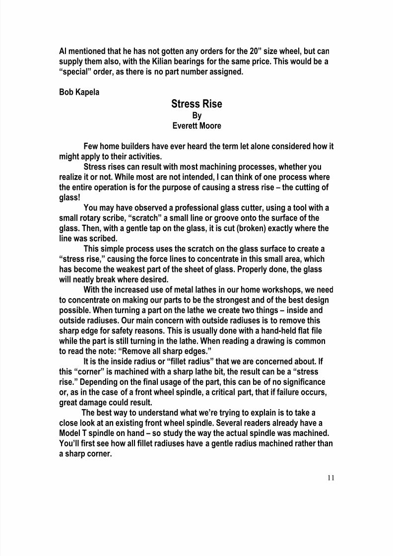
I started thinking about and came up with a way that I think willhave just as much structural integrity without the “T’s”. I started with a lengthof 1 ¼” OD structural tubing with a ¾” ID. This tubing was cut into (2) 3 ¾”lengths. Each will house a ¾” OD X ½” ID flange (shoulder) bushing at eachend to accept a ½” OD kingpin.
This is the tubing after milling a flat bottomed hole 3/16” deepand ¾” in diameter. This is where the spindle will be placed for welding.
8/14/2019 Vol 2. 1 jan-feb
http://slidepdf.com/reader/full/vol-2-1-jan-feb 14/22
14
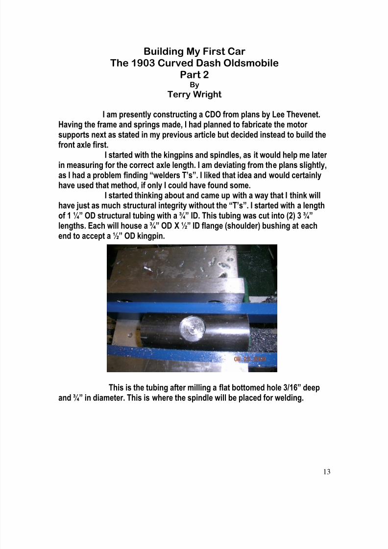
This is a ¾” X 6” shoulder bolt that I removed the head on. Iwill use two of these for my spindles.
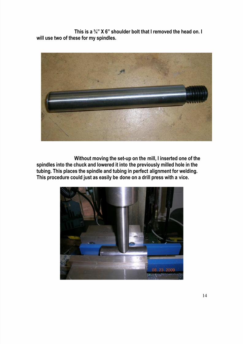
Without moving the set-up on the mill, I inserted one of thespindles into the chuck and lowered it into the previously milled hole in thetubing. This places the spindle and tubing in perfect alignment for welding.This procedure could just as easily be done on a drill press with a vice.
8/14/2019 Vol 2. 1 jan-feb
http://slidepdf.com/reader/full/vol-2-1-jan-feb 15/22
15
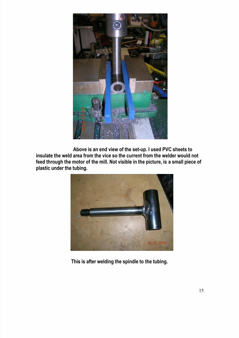
Above is an end view of the set-up. I used PVC sheets toinsulate the weld area from the vice so the current from the welder would notfeed through the motor of the mill. Not visible in the picture, is a small piece ofplastic under the tubing.
This is after welding the spindle to the tubing.
8/14/2019 Vol 2. 1 jan-feb
http://slidepdf.com/reader/full/vol-2-1-jan-feb 16/22
16
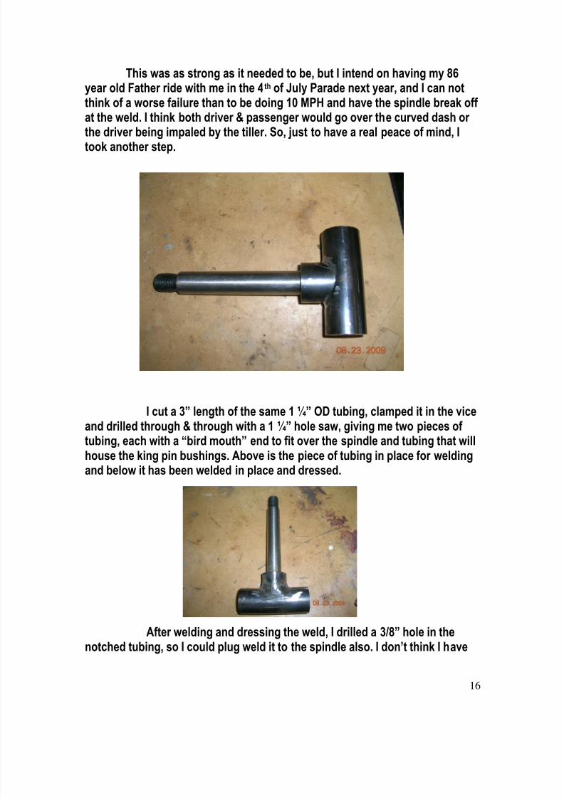
This was as strong as it needed to be, but I intend on having my 86year old Father ride with me in the 4th of July Parade next year, and I can notthink of a worse failure than to be doing 10 MPH and have the spindle break offat the weld. I think both driver & passenger would go over the curved dash orthe driver being impaled by the tiller. So, just to have a real peace of mind, Itook another step.
I cut a 3” length of the same 1 ¼” OD tubing, clamped it in the viceand drilled through & through with a 1 ¼” hole saw, giving me two pieces oftubing, each with a “bird mouth” end to fit over the spindle and tubing that willhouse the king pin bushings. Above is the piece of tubing in place for weldingand below it has been welded in place and dressed.
After welding and dressing the weld, I drilled a 3/8” hole in thenotched tubing, so I could plug weld it to the spindle also. I don’t think I have
8/14/2019 Vol 2. 1 jan-feb
http://slidepdf.com/reader/full/vol-2-1-jan-feb 17/22
17
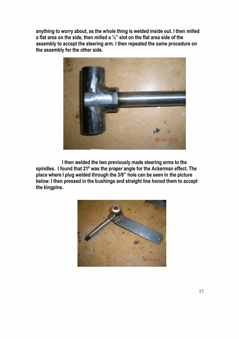
anything to worry about, as the whole thing is welded inside out. I then milleda flat area on the side, then milled a ¼” slot on the flat area side of theassembly to accept the steering arm. I then repeated the same procedure onthe assembly for the other side.
I then welded the two previously made steering arms to thespindles. I found that 21º was the proper angle for the Ackerman effect. Theplace where I plug welded through the 3/8” hole can be seen in the picturebelow. I then pressed in the bushings and straight line honed them to acceptthe kingpins.
8/14/2019 Vol 2. 1 jan-feb
http://slidepdf.com/reader/full/vol-2-1-jan-feb 18/22
18
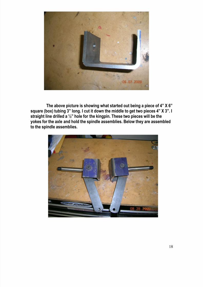
The above picture is showing what started out being a piece of 4” X 6”square (box) tubing 3” long. I cut it down the middle to get two pieces 4” X 3”. Istraight line drilled a ½” hole for the kingpin. These two pieces will be theyokes for the axle and hold the spindle assemblies. Below they are assembledto the spindle assemblies.
8/14/2019 Vol 2. 1 jan-feb
http://slidepdf.com/reader/full/vol-2-1-jan-feb 19/22
19
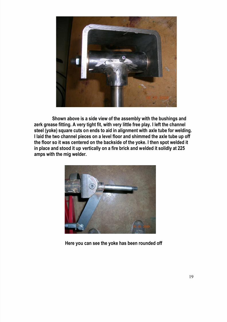
Shown above is a side view of the assembly with the bushings andzerk grease fitting. A very tight fit, with very little free play. I left the channelsteel (yoke) square cuts on ends to aid in alignment with axle tube for welding.I laid the two channel pieces on a level floor and shimmed the axle tube up offthe floor so it was centered on the backside of the yoke. I then spot welded itin place and stood it up vertically on a fire brick and welded it solidly at 225amps with the mig welder.
Here you can see the yoke has been rounded off
8/14/2019 Vol 2. 1 jan-feb
http://slidepdf.com/reader/full/vol-2-1-jan-feb 20/22
20
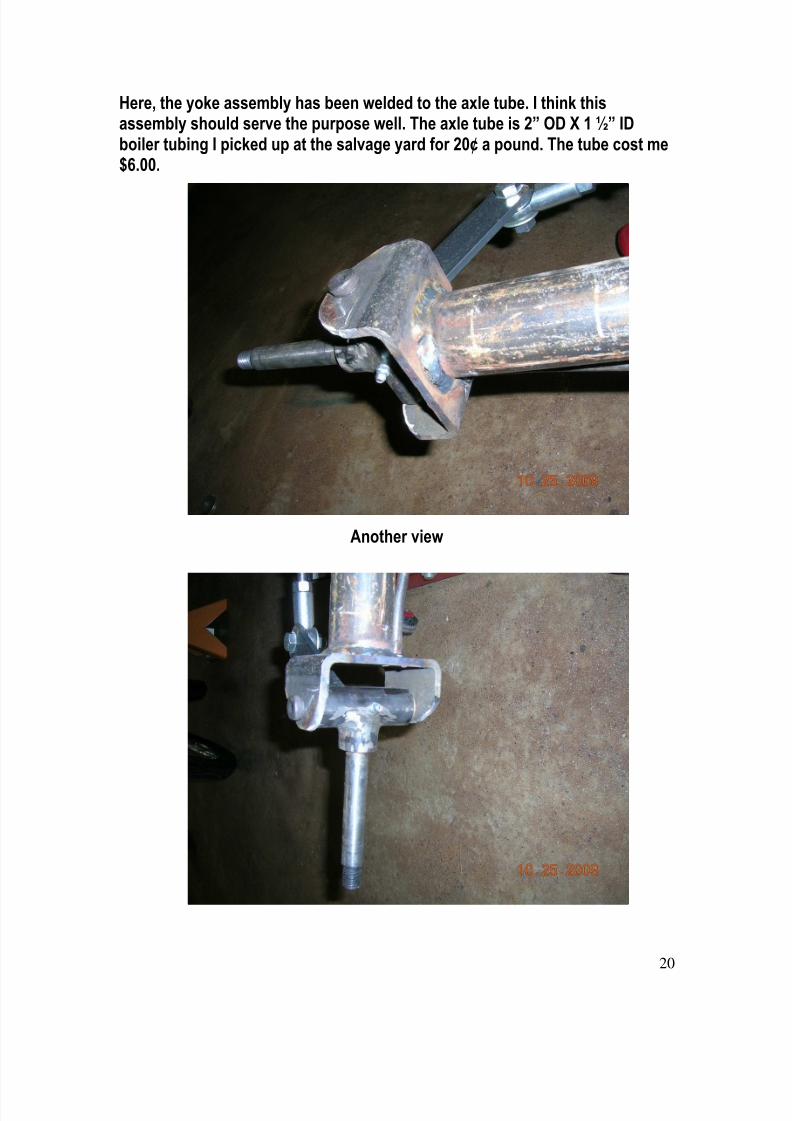
Here, the yoke assembly has been welded to the axle tube. I think thisassembly should serve the purpose well. The axle tube is 2” OD X 1 ½” IDboiler tubing I picked up at the salvage yard for 20¢ a pound. The tube cost me$6.00.
Another view

8/14/2019 Vol 2. 1 jan-feb
http://slidepdf.com/reader/full/vol-2-1-jan-feb 21/22
21
In closing, I know photos take up a lot of space in a documentwhen it is to be published on the internet. I am not good with any of thedrawing programs, so I let the photos help show the details. Next I will befabricating the spring perches, and mounting the axle to the springs. That willhave to be in a later issue of HCR News.
Terry
UPDATEI received an E-Mail from Terry a few days ago, in which he stated that
he had his CDO very close to completion, so lets all hope he allows us topublish pictures of his carriage in the next issue of the HCR News….:)Lee
NEW! NEW! NEW!Just in case some of you missed my post on the HCR Yahoo Site, Wenow have a very fine selection of headgear for that parade, car show or backyard bar-b-que. Top quality ball caps, in your favorite color featuring theregistered HCR logo, done in either gold or black. Now available at this site ata very reasonable price including shipping….:)
8/14/2019 Vol 2. 1 jan-feb
http://slidepdf.com/reader/full/vol-2-1-jan-feb 22/22
EDITORIAL
Well now builders, looks like Terry is doing a great job on his CDO build. This is the kind of building series other
builders want to see. If any of you have a building story likeTerry’s, Bob’s and Stu’s, or technical articles as the oneEverett sent in, I’m sure other builders would be interested in it.It takes just a few minutes, write it up, take a few pictures &send it to the HCR desk for publication.
You will help other builders and also help the HCR Newsletterto continue…
Again, from of all of the writers of the HCR Newsletter,
HAPPY NEW YEAR!
2010As an addition to the HCR Newsletter, Mr. Everett Moore hasgiven a “thumbs up” to having technical articles done byhimself or others, that appeared in Engines & Wheels, be re-published in the HCR Newsletter. One of the technical articleswill appear in each forthcoming issue of HCR News beginning
with the March/April issue. Should anyone wish the completeE&W News library, including Issue #50 “The Builders Manual”all on CD disc, it can be ordered from Mr. Moore by going to the“Plans” section of this site for ordering information.
Keep On Building!Lee