Embed Size (px)
Citation preview
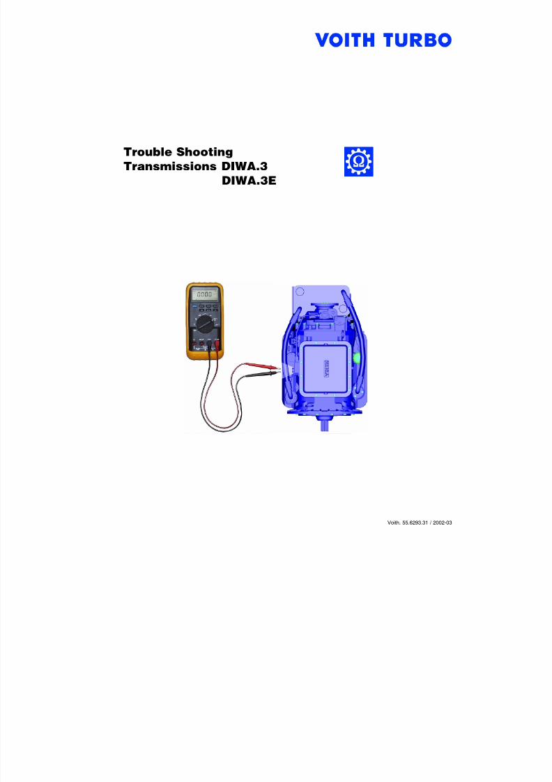
7/22/2019 Voith Diwa.3 Trouble Shooting
http://slidepdf.com/reader/full/voith-diwa3-trouble-shooting 1/70
Voith. 55.6293.31 / 2002-03
7/22/2019 Voith Diwa.3 Trouble Shooting
http://slidepdf.com/reader/full/voith-diwa3-trouble-shooting 2/70
Voith. Trouble Shooting I
It is your responsibility to familiarize yourself with the warnings and precautions described in thismanual.
This manual only contains the most important information, however. It is impossible to describeall conceivable mistakes and danger conditions.
Therefore, everybody who performs installation, repair or service work must very carefully en-sure that his personal safety or that of other persons is not at risk.
When replacing parts, always pay attention to the instructions in the spare parts catalog!
Design improvements which should be taken into account during transmission overhauls are de-scribed in detail in the „Customer service letters“.
Furthermore, all work must be performed in accordance with Voith requirements to prevent dam-age to parts and tools.
Danger! in conjunction with the symbol on the left is used if personal injury or danger tolife may result if work is not carried out carefully.
Note! in conjunction with the symbol on the left denotes information that is particularlyimportant.
7/22/2019 Voith Diwa.3 Trouble Shooting
http://slidepdf.com/reader/full/voith-diwa3-trouble-shooting 3/70
II Voith. Trouble Shooting
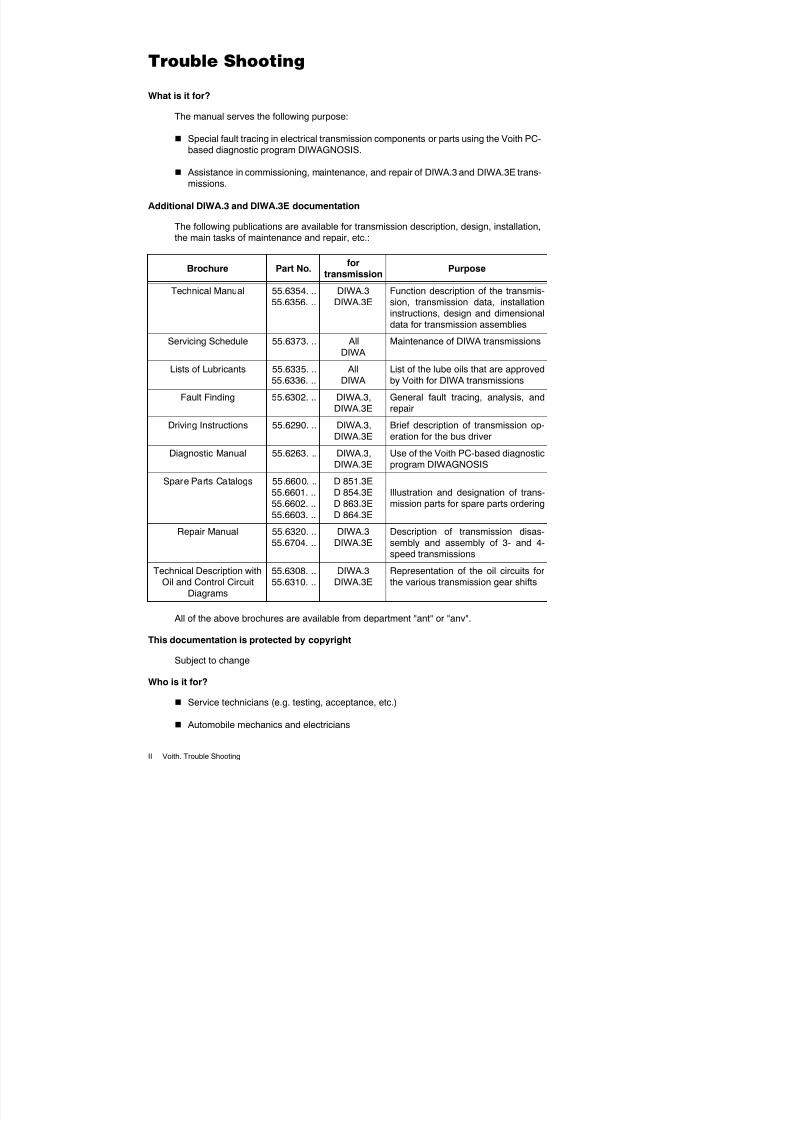
What is it for?
The manual serves the following purpose:
Special fault tracing in electrical transmission components or parts using the Voith PC-based diagnostic program DIWAGNOSIS.
Assistance in commissioning, maintenance, and repair of DIWA.3 and DIWA.3E trans-missions.
Additional DIWA.3 and DIWA.3E documentation
The following publications are available for transmission description, design, installation,the main tasks of maintenance and repair, etc.:
All of the above brochures are available from department "ant" or "anv".
This documentation is protected by copyright
Subject to change
Who is it for?
Service technicians (e.g. testing, acceptance, etc.)
Automobile mechanics and electricians
Brochure Part No.for
transmission
Purpose
Technical Manual 55.6354. ..55.6356. ..
DIWA.3DIWA.3E
Function description of the transmis-sion, transmission data, installationinstructions, design and dimensionaldata for transmission assemblies
Servicing Schedule 55.6373. .. AllDIWA
Maintenance of DIWA transmissions
Lists of Lubricants 55.6335. ..55.6336. ..
AllDIWA
List of the lube oils that are approvedby Voith for DIWA transmissions
Fault Finding 55.6302. .. DIWA.3,DIWA.3E
General fault tracing, analysis, andrepair
Driving Instructions 55.6290. .. DIWA.3,DIWA.3E
Brief description of transmission op-eration for the bus driver
Diagnostic Manual 55.6263. .. DIWA.3,DIWA.3E
Use of the Voith PC-based diagnosticprogram DIWAGNOSIS
Spare Parts Catalogs 55.6600. ..55.6601. ..55.6602. ..55.6603. ..
D 851.3ED 854.3ED 863.3ED 864.3E
Illustration and designation of trans-mission parts for spare parts ordering
Repair Manual 55.6320. ..55.6704. ..
DIWA.3DIWA.3E
Description of transmission disas-sembly and assembly of 3- and 4-
speed transmissions
Technical Description withOil and Control Circuit
Diagrams
55.6308. ..55.6310. ..
DIWA.3DIWA.3E
Representation of the oil circuits forthe various transmission gear shifts
7/22/2019 Voith Diwa.3 Trouble Shooting
http://slidepdf.com/reader/full/voith-diwa3-trouble-shooting 4/70
Voith. Trouble Shooting III
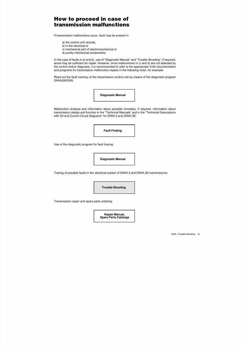
If transmission malfunctions occur, fault may be present in
a) the control unit records,b) in the electrical orc) mechanical part of electromechanical ord) purely mechanical components.
In the case of faults in a) and b), use of "Diagnostic Manual" and "Trouble Shooting", if required,alone may be sufficient for repair. However, since malfunctions in c) and d) are not detected bythe control and/or diagnosis, it is recommended to refer to the appropriate Voith documentationand programs for transmission malfunction repairs in the following order, for example:
Read out the fault memory of the transmission control unit by means of the diagnostic programDIWAGNOSIS:
Malfunction analysis and information about possible remedies, if required, information abouttransmission design and function in the "Technical Manuals" and in the "Technical Descriptionswith Oil and Control Circuit Diagrams" for DIWA.3 and DIWA.3E:
Use of the diagnostic program for fault tracing:
Tracing of possible faults in the electrical system of DIWA.3 and DIWA.3E transmissions:
Transmission repair and spare parts ordering:
Diagnostic Manual
Fault Finding
Diagnostic Manual
Trouble Shooting
Repair Manual,Spare Parts Catalogs

7/22/2019 Voith Diwa.3 Trouble Shooting
http://slidepdf.com/reader/full/voith-diwa3-trouble-shooting 5/70
IV Voith. Trouble Shooting
7/22/2019 Voith Diwa.3 Trouble Shooting
http://slidepdf.com/reader/full/voith-diwa3-trouble-shooting 6/70
Voith. Trouble Shooting V
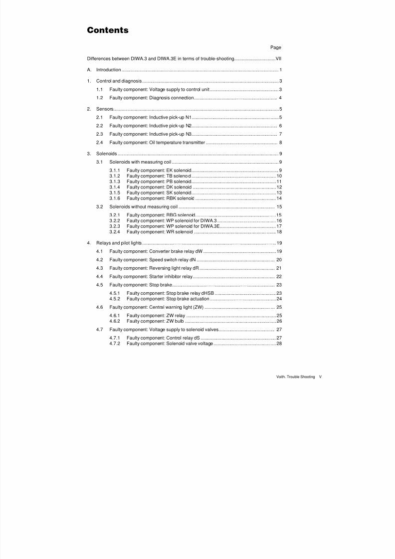
Page
Differences between DIWA.3 and DIWA.3E in terms of trouble-shooting................................VII
A. Introduction ......................................................................................................................... 1
1. Control and diagnosis......................................................................................................... 3
1.1 Faulty component: Voltage supply to control unit ..................................................... 3
1.2 Faulty component: Diagnosis connection................................................................ 4
2. Sensors...............................................................................................................................5
2.1 Faulty component: Inductive pick-up N1...................................................................5
2.2 Faulty component: Inductive pick-up N2.................................................................. 6
2.3 Faulty component: Inductive pick-up N3.................................................................. 7
2.4 Faulty component: Oil temperature transmitter ....................................................... 8
3. Solenoids ............................................................................................................................9
3.1 Solenoids with measuring coil .................................................................................. 9
3.1.1 Faulty component: EK solenoid................................................................... 93.1.2 Faulty component: TB solenoid ................................................................. 103.1.3 Faulty component: PB solenoid.................................................................113.1.4 Faulty component: DK solenoid ................................................................123.1.5 Faulty component: SK solenoid.................................................................133.1.6 Faulty component: RBK solenoid ..............................................................14
3.2 Solenoids without measuring coil .......................................................................... 15
3.2.1 Faulty component: RBG solenoid..............................................................153.2.2 Faulty component: WP solenoid for DIWA.3 .............................................163.2.3 Faulty component: WP solenoid for DIWA.3E...........................................173.2.4 Faulty component: WR solenoid ............................................................... 18
4. Relays and pilot lights ....................................................................................................... 19
4.1 Faulty component: Converter brake relay dW ........................................................19
4.2 Faulty component: Speed switch relay dN ............................................................ 20
4.3 Faulty component: Reversing light relay dR.......................................................... 21
4.4 Faulty component: Starter inhibitor relay............................................................... 22
4.5 Faulty component: Stop brake............................................................................... 23
4.5.1 Faulty component: Stop brake relay dHSB ............................................... 234.5.2 Faulty component: Stop brake actuation...................................................24
4.6 Faulty component: Central warning light (ZW) ...................................................... 25
4.6.1 Faulty component: ZW relay .....................................................................254.6.2 Faulty component: ZW bulb ......................................................................26
4.7 Faulty component: Voltage supply to solenoid valves........................................... 27
4.7.1 Faulty component: Control relay dS .......................................................... 27
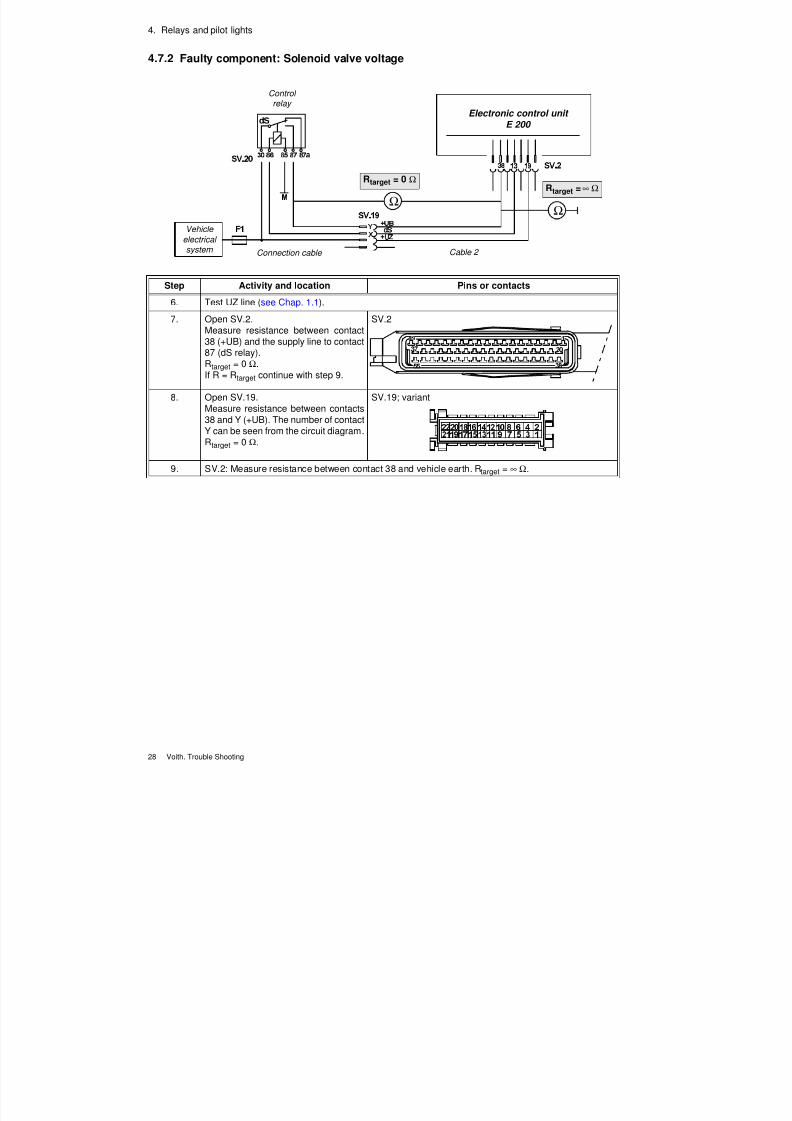
4.7.2 Faulty component: Solenoid valve voltage................................................28
7/22/2019 Voith Diwa.3 Trouble Shooting
http://slidepdf.com/reader/full/voith-diwa3-trouble-shooting 7/70
VI Voith. Trouble Shooting
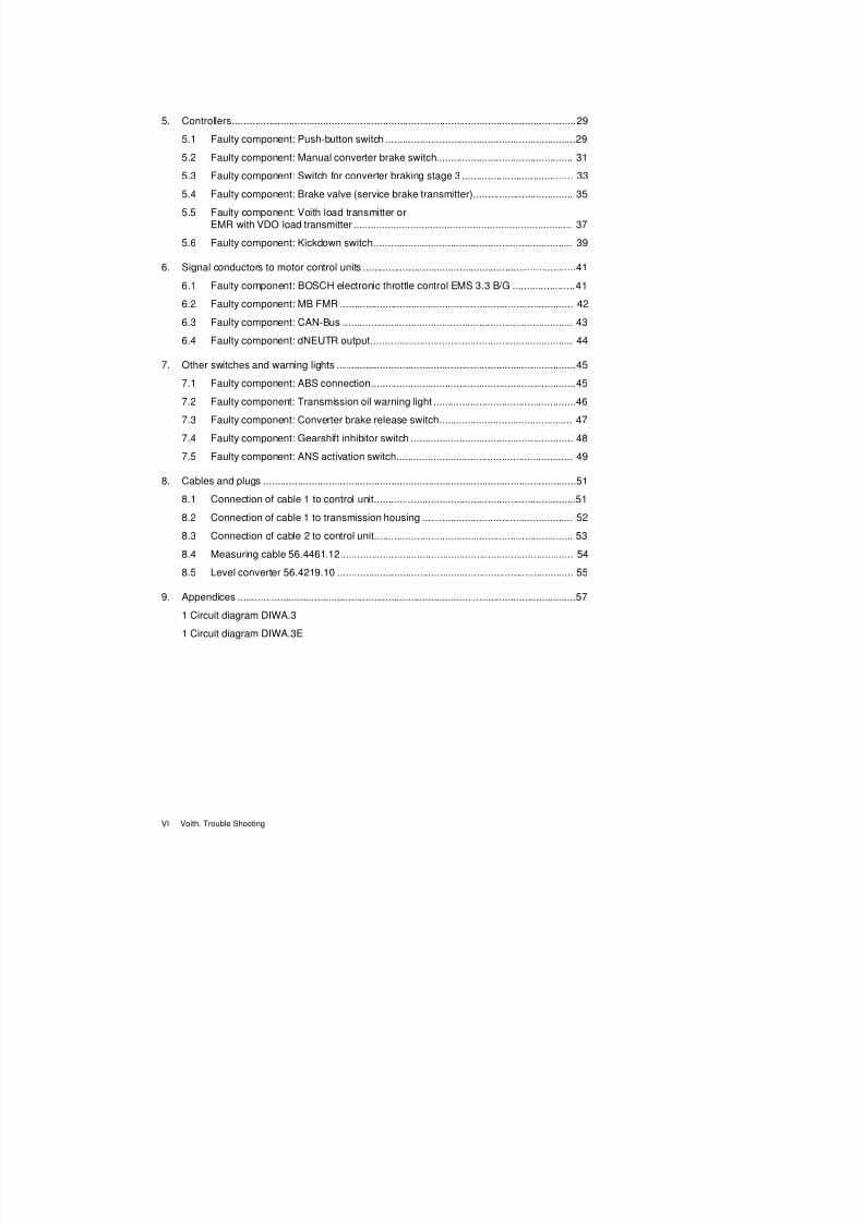
5. Controllers.........................................................................................................................29
5.1 Faulty component: Push-button switch ...................................................................29
5.2 Faulty component: Manual converter brake switch................................................ 31
5.3 Faulty component: Switch for converter braking stage 3 ....................................... 33
5.4 Faulty component: Brake valve (service brake transmitter)................................... 35
5.5 Faulty component: Voith load transmitter orEMR with VDO load transmitter ............................................................................. 37
5.6 Faulty component: Kickdown switch...................................................................... 39
6. Signal conductors to motor control units ...........................................................................41
6.1 Faulty component: BOSCH electronic throttle control EMS 3.3 B/G ......................41
6.2 Faulty component: MB FMR .................................................................................. 42
6.3 Faulty component: CAN-Bus ................................................................................. 43
6.4 Faulty component: dNEUTR output....................................................................... 44
7. Other switches and warning lights ....................................................................................45
7.1 Faulty component: ABS connection........................................................................45
7.2 Faulty component: Transmission oil warning light ..................................................46
7.3 Faulty component: Converter brake release switch............................................... 47
7.4 Faulty component: Gearshift inhibitor switch ......................................................... 48
7.5 Faulty component: ANS activation switch.............................................................. 49
8. Cables and plugs ..............................................................................................................51
8.1 Connection of cable 1 to control unit.......................................................................51
8.2 Connection of cable 1 to transmission housing ..................................................... 52
8.3 Connection of cable 2 to control unit...................................................................... 53
8.4 Measuring cable 56.4461.12.................................................................................. 54
8.5 Level converter 56.4219.10 ................................................................................... 55
9. Appendices .......................................................................................................................57
1 Circuit diagram DIWA.3
1 Circuit diagram DIWA.3E
7/22/2019 Voith Diwa.3 Trouble Shooting
http://slidepdf.com/reader/full/voith-diwa3-trouble-shooting 8/70
Voith. Trouble Shooting VII
As mentioned in the next chapter, only parts or components that can be accessed by the Voithdiagnostic system are concerned here, i. e. mainly electrical parts.
The decisive reference is the circuit diagram. Since there are hardly any fundamental differencesbetween the circuit diagrams of DIWA.3 and DIWA.3E transmissions (see chap. 9. Circuit dia-gram DIWA.3 55.3705.20 and Circuit diagram DIWA.3E 55.6168.10), however, the differencesin fault-tracing procedures are minor, too.
See also:
Chap. 3.2.2 and Chap. 3.2.3,
Chap. 8.1,
Chap. 8.2,
Chap. 8.4

7/22/2019 Voith Diwa.3 Trouble Shooting
http://slidepdf.com/reader/full/voith-diwa3-trouble-shooting 9/70
VIII Voith. Trouble Shooting
7/22/2019 Voith Diwa.3 Trouble Shooting
http://slidepdf.com/reader/full/voith-diwa3-trouble-shooting 10/70
Voith. Trouble Shooting 1
Purpose
The purpose of this manual is to enable the service engineer to systematically search for defec-tive components or malfunctions in DIWA.3 and DIWA.3E transmissions. However, the manualonly covers parts or components that can be tested using the Voith diagnostic system, i. e. most-ly electrical parts.
Before trouble-shooting
The following preparations described in the "Diagnostic Manual" are necessary before trouble-shooting can begin:
Connect a suitable PC (laptop) to the transmission control via the cable (level converter) pro-vided for this purpose
Start the diagnostic program
Start communication
Read fault memory (function B)
Test faulty components individually once again (functions C, D, E, F, G, H and J). This is tofind out whether the fault still exists.
How to proceed with the "Trouble Shooting"
The trouble-shooting procedure is as follows:
1. Switch off vehicle ignition for all measurements unless you are expressly instructed at somepoint in this manual not to do so.
2. Open plug connection between control unit and cable 1 or cable 2. This is where the test mea-surements should begin.
If measured values differ from set points, narrow down the number of potentially defective partsor components by proceeding with the next step.With regard to relay and plug designs and theircontact designations the circuit diagrams 55.3705.20 for DIWA.3 and 55.6168.10 for DIWA.3Eare used, provided that the respective components were shown in it.
After completion of "Trouble Shooting"
Erase fault memory after repair of the defect by pressing function key B (see "Diagnostic Manu-al").
Danger! Always apply the parking brake before proceeding with diagnosis at vehiclestandstill.
Note! In the case of other circuit diagrams, relay and plug designs and their contact des-ignations may differ.

7/22/2019 Voith Diwa.3 Trouble Shooting
http://slidepdf.com/reader/full/voith-diwa3-trouble-shooting 11/70
2 Voith. Trouble Shooting
7/22/2019 Voith Diwa.3 Trouble Shooting
http://slidepdf.com/reader/full/voith-diwa3-trouble-shooting 12/70
Voith. Trouble Shooting 3
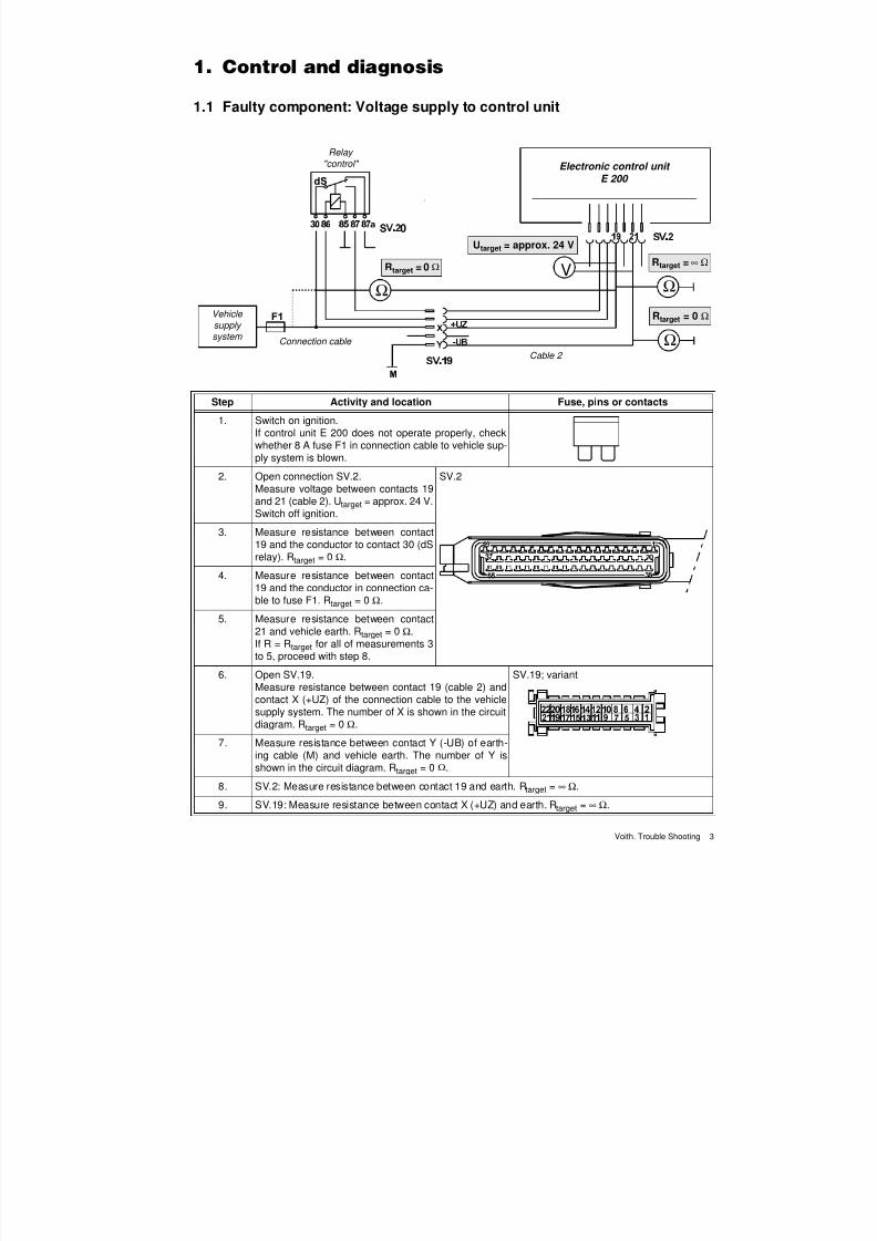
1.1 Faulty component: Voltage supply to control unit
Ω
V
Ω
Ω
Relay "control" Electronic control unit
E 200
Vehicle
supply
system
Cable 2
Connection cable
Rtarget = 0 Ω
Utarget = approx. 24 V
Rtarget = ∞ Ω
Rtarget = 0 Ω
Step Activity and location Fuse, pins or contacts
1. Switch on ignition.If control unit E 200 does not operate properly, checkwhether 8 A fuse F1 in connection cable to vehicle sup-
ply system is blown.2. Open connection SV.2.
Measure voltage between contacts 19and 21 (cable 2). Utarget = approx. 24 V.Switch off ignition.
SV.2
3. Measure resistance between contact19 and the conductor to contact 30 (dSrelay). Rtarget = 0 Ω.
4. Measure resistance between contact19 and the conductor in connection ca-ble to fuse F1. Rtarget = 0 Ω.
5. Measure resistance between contact21 and vehicle earth. Rtarget = 0 Ω.If R = Rtarget for all of measurements 3to 5, proceed with step 8.
6. Open SV.19.Measure resistance between contact 19 (cable 2) andcontact X (+UZ) of the connection cable to the vehiclesupply system. The number of X is shown in the circuitdiagram. Rtarget = 0 Ω.
SV.19; variant
7. Measure resistance between contact Y (-UB) of earth-ing cable (M) and vehicle earth. The number of Y is
shown in the circuit diagram. Rtarget = 0 Ω.
8. SV.2: Measure resistance between contact 19 and earth. Rtarget = ∞ Ω.
9. SV.19: Measure resistance between contact X (+UZ) and earth. Rtarget = ∞ Ω.
7/22/2019 Voith Diwa.3 Trouble Shooting
http://slidepdf.com/reader/full/voith-diwa3-trouble-shooting 13/70
1. Control and diagnosis
4 Voith. Trouble Shooting
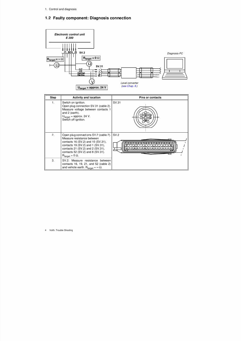
1.2 Faulty component: Diagnosis connection
Ω
Ω
V
Rtarget = ∞ Ω Rtarget = 0 Ω
Utarget = approx. 24 VLevel converter ( see Chap. 8. )
Diagnosis-PC
Electronic control unit
E 200
Step Activity and location Pins or contacts
1. Switch on ignition.Open plug connection SV.31 (cable 2).Measure voltage between contacts 1and 2 (earth).Utarget = approx. 24 V.Switch off ignition.
SV.31
2. Open plug connections SV.2 (cable 2).Measure resistance betweencontacts 16 (SV.2) and 10 (SV.31),contacts 19 (SV.2) and 1 (SV.31),contacts 21 (SV.2) and 2 (SV.31),contacts 52 (SV.2) and 8 (SV.31).Rtarget = 0 Ω.
SV.2
3. SV.2: Measure resistance betweencontacts 16, 19, 21, and 52 (cable 2)
and vehicle earth. Rtarget = ∞ Ω.
7/22/2019 Voith Diwa.3 Trouble Shooting
http://slidepdf.com/reader/full/voith-diwa3-trouble-shooting 14/70
Voith. Trouble Shooting 5
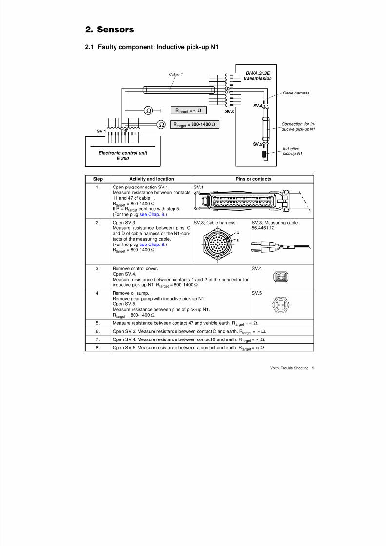
2.1 Faulty component: Inductive pick-up N1
Ω
Ω
DIWA.3/.3E
transmission Cable 1
Cable harness
Connection for in-
ductive pick-up N1
Inductive
pick-up N1Electronic control unit
E 200
Rtarget = ∞ Ω
Rtarget = 800-1400 Ω
Step Activity and location Pins or contacts
1. Open plug connection SV.1.Measure resistance between contacts11 and 47 of cable 1.
Rtarget = 800-1400 Ω.If R = Rtarget continue with step 5.(For the plug see Chap. 8.)
SV.1
2. Open SV.3.Measure resistance between pins Cand D of cable harness or the N1-con-tacts of the measuring cable.(For the plug see Chap. 8.)Rtarget = 800-1400 Ω.
SV.3; Cable harness SV.3; Measuring cable56.4461.12
3. Remove control cover.Open SV.4.Measure resistance between contacts 1 and 2 of the connector forinductive pick-up N1. Rtarget = 800-1400 Ω.
SV.4
4. Remove oil sump.Remove gear pump with inductive pick-up N1.Open SV.5.Measure resistance between pins of pick-up N1.Rtarget = 800-1400 Ω.
SV.5
5. Measure resistance between contact 47 and vehicle earth. Rtarget = ∞ Ω.
6. Open SV.3. Measure resistance between contact C and earth. Rtarget = ∞ Ω.
7. Open SV.4. Measure resistance between contact 2 and earth. Rtarget = ∞ Ω.
8. Open SV.5. Measure resistance between a contact and earth. Rtarget = ∞ Ω.
7/22/2019 Voith Diwa.3 Trouble Shooting
http://slidepdf.com/reader/full/voith-diwa3-trouble-shooting 15/70
2. Sensors
6 Voith. Trouble Shooting
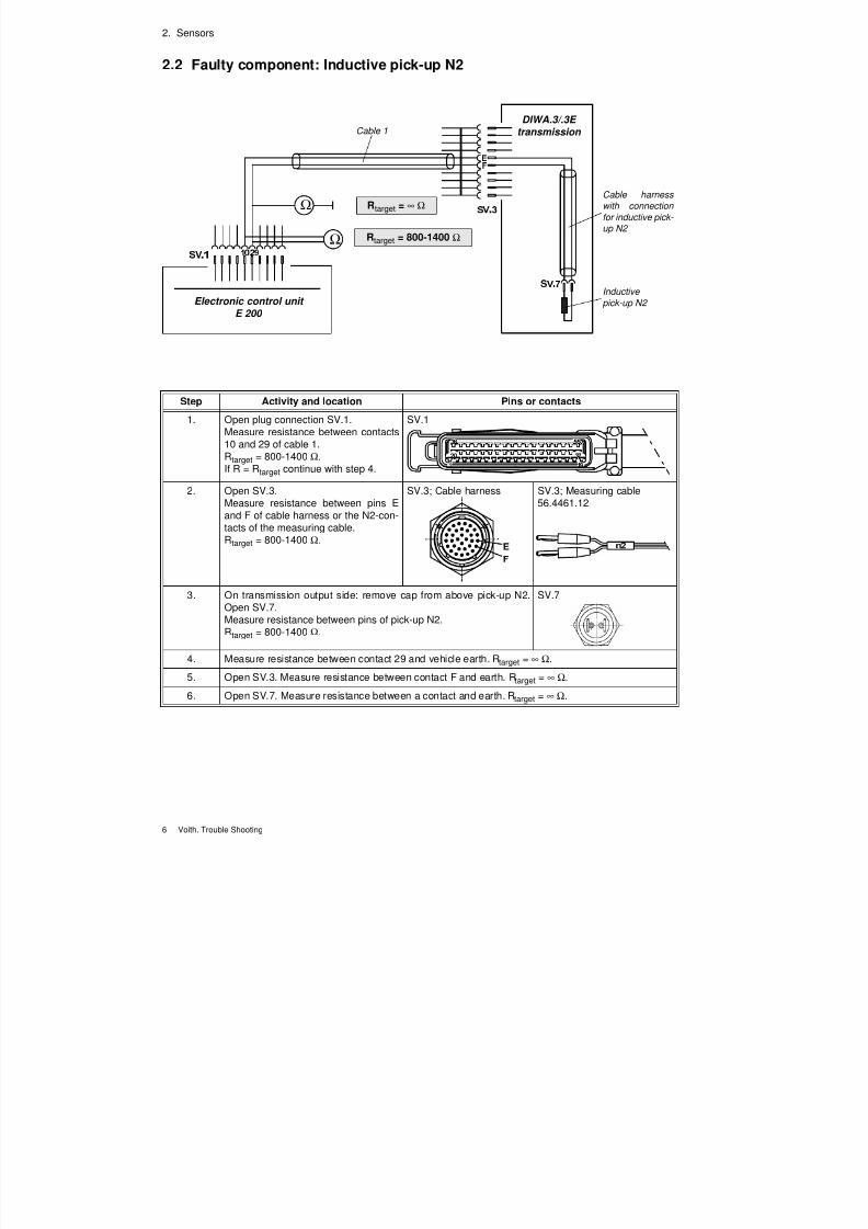
2.2 Faulty component: Inductive pick-up N2
Ω
Ω
DIWA.3/.3E
transmission Cable 1
Cable harness
with connection
for inductive pick-
up N2
Inductive
pick-up N2 Electronic control unit E 200
Rtarget = ∞ Ω
Rtarget = 800-1400 Ω
Step Activity and location Pins or contacts
1. Open plug connection SV.1.Measure resistance between contacts10 and 29 of cable 1.
Rtarget = 800-1400 Ω.If R = Rtarget continue with step 4.
SV.1
2. Open SV.3.Measure resistance between pins Eand F of cable harness or the N2-con-tacts of the measuring cable.Rtarget = 800-1400 Ω.
SV.3; Cable harness SV.3; Measuring cable56.4461.12
3. On transmission output side: remove cap from above pick-up N2.
Open SV.7.Measure resistance between pins of pick-up N2.Rtarget = 800-1400 Ω.
SV.7
4. Measure resistance between contact 29 and vehicle earth. Rtarget = ∞ Ω.
5. Open SV.3. Measure resistance between contact F and earth. Rtarget = ∞ Ω.
6. Open SV.7. Measure resistance between a contact and earth. Rtarget = ∞ Ω.
7/22/2019 Voith Diwa.3 Trouble Shooting
http://slidepdf.com/reader/full/voith-diwa3-trouble-shooting 16/70
2. Sensors
Voith. Trouble Shooting 7
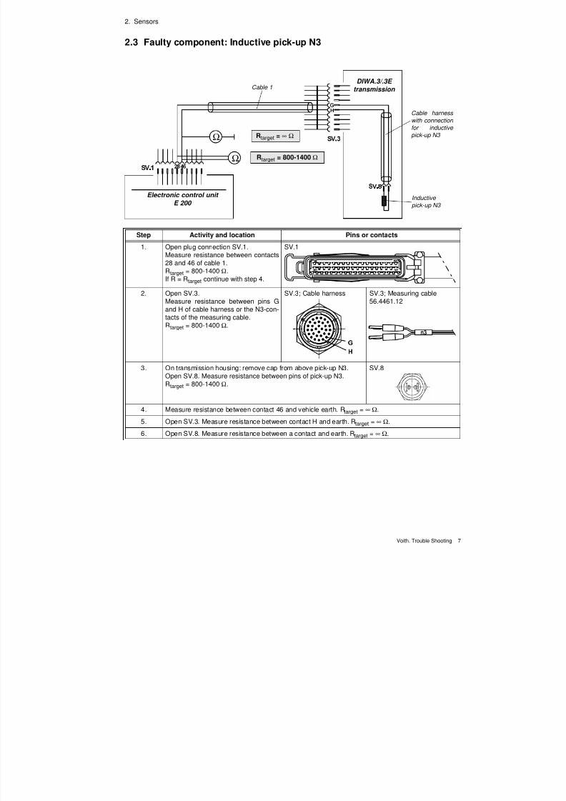
2.3 Faulty component: Inductive pick-up N3
Ω
Ω
DIWA.3/.3E
transmission Cable 1
Cable harness
with connection
for inductive
pick-up N3
Inductive pick-up N3
Electronic control unit
E 200
Rtarget = ∞ Ω
Rtarget = 800-1400 Ω
Step Activity and location Pins or contacts
1. Open plug connection SV.1.Measure resistance between contacts28 and 46 of cable 1.Rtarget = 800-1400 Ω.If R = Rtarget continue with step 4.
SV.1
2. Open SV.3.Measure resistance between pins Gand H of cable harness or the N3-con-tacts of the measuring cable.Rtarget = 800-1400 Ω.
SV.3; Cable harness SV.3; Measuring cable56.4461.12
3. On transmission housing: remove cap from above pick-up N3.Open SV.8. Measure resistance between pins of pick-up N3.Rtarget = 800-1400 Ω.
SV.8
4. Measure resistance between contact 46 and vehicle earth. Rtarget = ∞ Ω.
5. Open SV.3. Measure resistance between contact H and earth. Rtarget = ∞ Ω.
6. Open SV.8. Measure resistance between a contact and earth. Rtarget = ∞ Ω.
7/22/2019 Voith Diwa.3 Trouble Shooting
http://slidepdf.com/reader/full/voith-diwa3-trouble-shooting 17/70
2. Sensors
8 Voith. Trouble Shooting
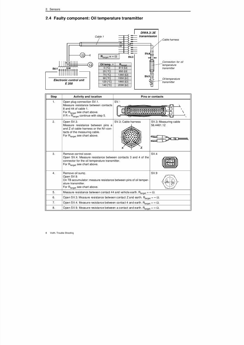
2.4 Faulty component: Oil temperature transmitter
Ω
Ω
DIWA.3/.3E
transmission Cable 1Cable harness
Oil temperature
transmitter Electronic control unit
E 200
Rtarget = ∞ Ω
Connection for oil temperature
transmitter
Oil temp. ϑ Rtarget
0 [°C] 810 [Ω]
20 [°C] 950 [Ω]
70 [°C] 1360 [Ω]
90 [°C] 1550 [Ω]
120 [°C] 1860 [Ω]
140 [°C] 2090 [Ω]
Step Activity and location Pins or contacts
1. Open plug connection SV.1.Measure resistance between contacts8 and 44 of cable 1.For Rtarget see chart above.If R = Rtarget continue with step 5.
SV.1
2. Open SV.3.Measure resistance between pins a
and Z of cable harness or the N1-con-tacts of the measuring cable.For Rtarget see chart above.
SV.3; Cable harness SV.3; Measuring cable56.4461.12
3. Remove control cover.Open SV.4. Measure resistance between contacts 3 and 4 of theconnector for the oil temperature transmitter.For Rtarget see chart above.
SV.4
4. Remove oil sump.Open SV.9.On TB accumulator: measure resistance between pins of oil temper-ature transmitter.For Rtarget see chart above.
SV.9
5. Measure resistance between contact 44 and vehicle earth. Rtarget = ∞ Ω.
6. Open SV.3. Measure resistance between contact Z and earth. Rtarget = ∞ Ω.
7. Open SV.4. Measure resistance between contact 4 and earth. Rtarget = ∞ Ω.
8. Open SV.9. Measure resistance between a contact and earth. Rtarget = ∞ Ω.
7/22/2019 Voith Diwa.3 Trouble Shooting
http://slidepdf.com/reader/full/voith-diwa3-trouble-shooting 18/70
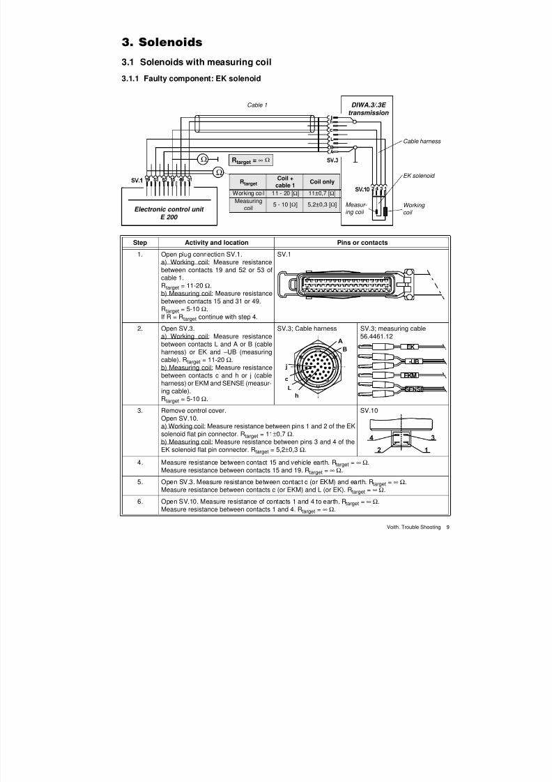
Voith. Trouble Shooting 9
3.1 Solenoids with measuring coil
3.1.1 Faulty component: EK solenoid
Ω
Ω
DIWA.3/.3E
transmission
Cable harness
Electronic control unit
E 200
Cable 1
EK solenoid
Working
coil
Measur-
ing coil
Rtarget = ∞ Ω
RtargetCoil +
cable 1Coil only
Working coil 11 - 20 [Ω] 11±0,7 [Ω]Measuring
coil5 - 10 [Ω] 5,2±0,3 [Ω]
Step Activity and location Pins or contacts
1. Open plug connection SV.1.a) Working coil: Measure resistancebetween contacts 19 and 52 or 53 ofcable 1.R
target = 11-20 Ω.
b) Measuring coil: Measure resistancebetween contacts 15 and 31 or 49.Rtarget = 5-10 Ω.If R = Rtarget continue with step 4.
SV.1
2. Open SV.3.a) Working coil: Measure resistancebetween contacts L and A or B (cableharness) or EK and – UB (measuringcable). Rtarget = 11-20 Ω.b) Measuring coil: Measure resistancebetween contacts c and h or j (cable
harness) or EKM and SENSE (measur-ing cable).Rtarget = 5-10 Ω.
SV.3; Cable harness SV.3; measuring cable56.4461.12
3. Remove control cover.Open SV.10.a) Working coil: Measure resistance between pins 1 and 2 of the EKsolenoid flat pin connector. Rtarget = 11±0,7 Ω.b) Measuring coil: Measure resistance between pins 3 and 4 of theEK solenoid flat pin connector. Rtarget = 5,2±0,3 Ω.
SV.10
4. Measure resistance between contact 15 and vehicle earth. Rtarget = ∞ Ω.Measure resistance between contacts 15 and 19. Rtarget = ∞ Ω.
5. Open SV.3. Measure resistance between contact c (or EKM) and earth. Rtarget = ∞ Ω.Measure resistance between contacts c (or EKM) and L (or EK). Rtarget = ∞ Ω.
6. Open SV.10. Measure resistance of contacts 1 and 4 to earth. Rtarget = ∞ Ω.Measure resistance between contacts 1 and 4. Rtarget = ∞ Ω.
7/22/2019 Voith Diwa.3 Trouble Shooting
http://slidepdf.com/reader/full/voith-diwa3-trouble-shooting 19/70
3. Solenoids
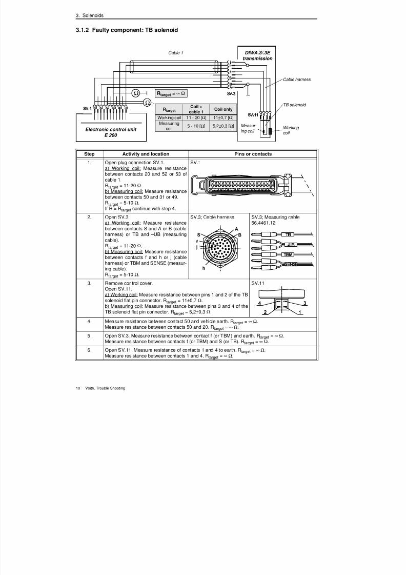
10 Voith. Trouble Shooting
3.1.2 Faulty component: TB solenoid
Ω
Ω
DIWA.3/.3E
transmission
Cable harness
Electronic control unit
E 200
Cable 1
TB solenoid
Working
coil
Measur-
ing coil
Rtarget = ∞ Ω
RtargetCoil +
cable 1Coil only
Working coil 11 - 20 [Ω] 11±0,7 [Ω]
Measuringcoil
5 - 10 [Ω] 5,2±0,3 [Ω]
Step Activity and location Pins or contacts
1. Open plug connection SV.1.a) Working coil: Measure resistancebetween contacts 20 and 52 or 53 ofcable 1.Rtarget = 11-20 Ω.b) Measuring coil: Measure resistancebetween contacts 50 and 31 or 49.Rtarget = 5-10 Ω.If R = Rtarget continue with step 4.
SV.1
2. Open SV.3.a) Working coil: Measure resistancebetween contacts S and A or B (cableharness) or TB and – UB (measuringcable).Rtarget = 11-20 Ω.b) Measuring coil: Measure resistancebetween contacts f and h or j (cableharness) or TBM and SENSE (measur-ing cable).Rtarget = 5-10 Ω.
SV.3; Cable harness SV.3; Measuring cable56.4461.12
3. Remove control cover.Open SV.11.a) Working coil: Measure resistance between pins 1 and 2 of the TBsolenoid flat pin connector. Rtarget = 11±0,7 Ω.b) Measuring coil: Measure resistance between pins 3 and 4 of theTB solenoid flat pin connector. Rtarget = 5,2±0,3 Ω.
SV.11
4. Measure resistance between contact 50 and vehicle earth. Rtarget = ∞ Ω.Measure resistance between contacts 50 and 20. Rtarget = ∞ Ω.
5. Open SV.3. Measure resistance between contact f (or TBM) and earth. Rtarget = ∞ Ω.Measure resistance between contacts f (or TBM) and S (or TB). Rtarget = ∞ Ω.
6. Open SV.11. Measure resistance of contacts 1 and 4 to earth. Rtarget = ∞ Ω.
Measure resistance between contacts 1 and 4. Rtarget = ∞ Ω.
7/22/2019 Voith Diwa.3 Trouble Shooting
http://slidepdf.com/reader/full/voith-diwa3-trouble-shooting 20/70
3. Solenoids
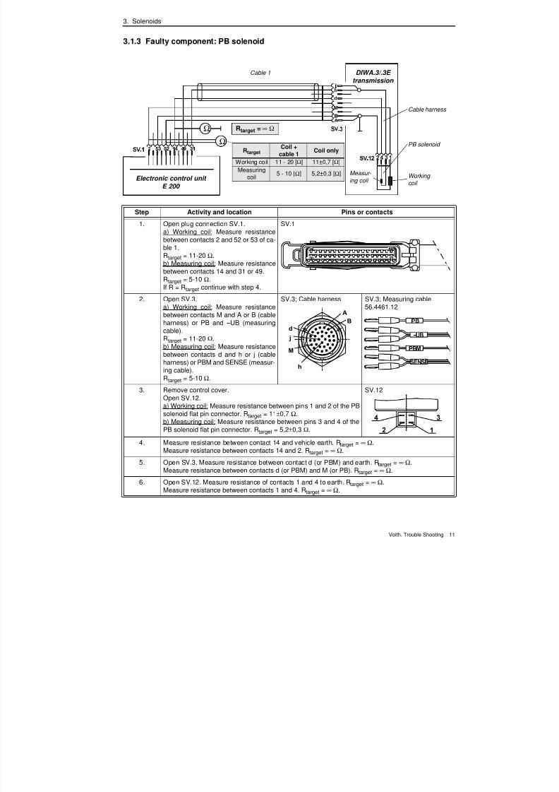
Voith. Trouble Shooting 11
3.1.3 Faulty component: PB solenoid
Ω
Ω
DIWA.3/.3E
transmission
Cable harness
Electronic control unit
E 200
Cable 1
PB solenoid
Working
coil
Measur-
ing coil
Rtarget = ∞ Ω
RtargetCoil +
cable 1Coil only
Working coil 11 - 20 [Ω] 11±0,7 [Ω]
Measuringcoil
5 - 10 [Ω] 5,2±0,3 [Ω]
Step Activity and location Pins or contacts
1. Open plug connection SV.1.a) Working coil: Measure resistancebetween contacts 2 and 52 or 53 of ca-ble 1.Rtarget = 11-20 Ω.b) Measuring coil: Measure resistancebetween contacts 14 and 31 or 49.Rtarget = 5-10 Ω.If R = Rtarget continue with step 4.
SV.1
2. Open SV.3.a) Working coil: Measure resistancebetween contacts M and A or B (cableharness) or PB and – UB (measuringcable).Rtarget = 11-20 Ω.b) Measuring coil: Measure resistancebetween contacts d and h or j (cableharness) or PBM and SENSE (measur-ing cable).Rtarget = 5-10 Ω.
SV.3; Cable harness SV.3; Measuring cable56.4461.12
3. Remove control cover.Open SV.12.a) Working coil: Measure resistance between pins 1 and 2 of the PBsolenoid flat pin connector. Rtarget = 11±0,7 Ω.b) Measuring coil: Measure resistance between pins 3 and 4 of thePB solenoid flat pin connector. Rtarget = 5,2±0,3 Ω.
SV.12
4. Measure resistance between contact 14 and vehicle earth. Rtarget = ∞ Ω.Measure resistance between contacts 14 and 2. Rtarget = ∞ Ω.
5. Open SV.3. Measure resistance between contact d (or PBM) and earth. Rtarget = ∞ Ω.Measure resistance between contacts d (or PBM) and M (or PB). Rtarget = ∞ Ω.
6. Open SV.12. Measure resistance of contacts 1 and 4 to earth. Rtarget = ∞ Ω.
Measure resistance between contacts 1 and 4. Rtarget = ∞ Ω.

7/22/2019 Voith Diwa.3 Trouble Shooting
http://slidepdf.com/reader/full/voith-diwa3-trouble-shooting 21/70
3. Solenoids
12 Voith. Trouble Shooting
3.1.4 Faulty component: DK solenoid
Ω
Ω
DIWA.3/.3E
transmission
Cable harness
Electronic control unit
E 200
Cable 1
DK solenoid
Working
coil
Measur-
ing coil
Rtarget = ∞ Ω
RtargetCoil +
cable 1Coil only
Working coil 11 - 20 [Ω] 11±0,7 [Ω]
Measuringcoil
5 - 10 [Ω] 5,2±0,3 [Ω]
Step Activity and location Pins or contacts
1. Open plug connection SV.1.a) Working coil: Measure resistancebetween contacts 37 and 52 or 53 ofcable 1.Rtarget = 11-20 Ω.b) Measuring coil: Measure resistancebetween contacts 51 and 31 or 49.Rtarget = 5-10 Ω.If R = Rtarget continue with step 4.
SV.1
2. Open SV.3.a) Working coil: Measure resistancebetween contacts K and A or B (cableharness) or DK and – UB (measuringcable).Rtarget = 11-20 Ω.b) Measuring coil: Measure resistancebetween contacts b and h or j (cableharness) or DKM and SENSE (mea-suring cable).Rtarget = 5-10 Ω.
SV.3; Cable harness SV.3; Measuring cable56.4461.12
3. Remove control cover.Open SV.13.a) Working coil: Measure resistance between pins 1 and 2 of the DKsolenoid flat pin connector. Rtarget = 11±0,7 Ω.b) Measuring coil: Measure resistance between pins 3 and 4 of theDK solenoid flat pin connector. Rtarget = 5,2±0,3 Ω.
SV.13
4. Measure resistance between contact 51 and vehicle earth. Rtarget = ∞ Ω.Measure resistance between contacts 51 and 37. Rtarget = ∞ Ω.
5. Open SV.3. Measure resistance between contact b (or DKM) and earth. Rtarget = ∞ Ω.Measure resistance between contacts b (or DKM) and K (or DK). Rtarget = ∞ Ω.
6. Open SV.13. Measure resistance of contacts 1 and 4 to earth. Rtarget = ∞ Ω.
Measure resistance between contacts 1 and 4. Rtarget = ∞ Ω.

7/22/2019 Voith Diwa.3 Trouble Shooting
http://slidepdf.com/reader/full/voith-diwa3-trouble-shooting 22/70
3. Solenoids
Voith. Trouble Shooting 13
3.1.5 Faulty component: SK solenoid
Ω
Ω
DIWA.3/.3E
transmission
Cable harness
Electronic control unit
E 200
Cable 1
SK solenoid
Working
coil
Measur-
ing coil
Rtarget = ∞ Ω
RtargetCoil +
cable 1Coil only
Working coil 11 - 20 [Ω] 11±0,7 [Ω]
Measuringcoil
5 - 10 [Ω] 5,2±0,3 [Ω]
Step Activity and location Pins or contacts
1. Open plug connection SV.1.a) Working coil: Measure resistancebetween contacts 18 and 52 or 53 ofcable 1.Rtarget = 11-20 Ω.b) Measuring coil: Measure resistancebetween contacts 33 and 31 or 49.Rtarget = 5-10 Ω.If R = Rtarget continue with step 4.
SV.1
2. Open SV.3.a) Working coil: Measure resistancebetween contacts U and A or B (cableharness) or SK and – UB (measuringcable).Rtarget = 11-20 Ω.b) Measuring coil: Measure resistancebetween contacts g and h or j (cableharness) or SKM and SENSE (measur-ing cable).Rtarget = 5-10 Ω.
SV.3; Cable harness SV.3; Measuring cable56.4461.12
3. Remove control cover.Open SV.14.a) Working coil: Measure resistance between pins 1 and 2 of the SKsolenoid flat pin connector. Rtarget = 11±0,7 Ω.b) Measuring coil: Measure resistance between pins 3 and 4 of theSK solenoid flat pin connector. Rtarget = 5,2±0,3 Ω.
SV.14
4. Measure resistance between contact 33 and vehicle earth. Rtarget = ∞ Ω.Measure resistance between contacts 33 and 18. Rtarget = ∞ Ω.
5. Open SV.3. Measure resistance between contact g (or SKM) and earth. Rtarget = ∞ Ω.Measure resistance between contacts g (or SKM) and U (or SK). Rtarget = ∞ Ω.
6. Open SV.14. Measure resistance of contacts 1 and 4 to earth. Rtarget = ∞ Ω.
Measure resistance between contacts 1 and 4. Rtarget = ∞ Ω.
7/22/2019 Voith Diwa.3 Trouble Shooting
http://slidepdf.com/reader/full/voith-diwa3-trouble-shooting 23/70
3. Solenoids
14 Voith. Trouble Shooting
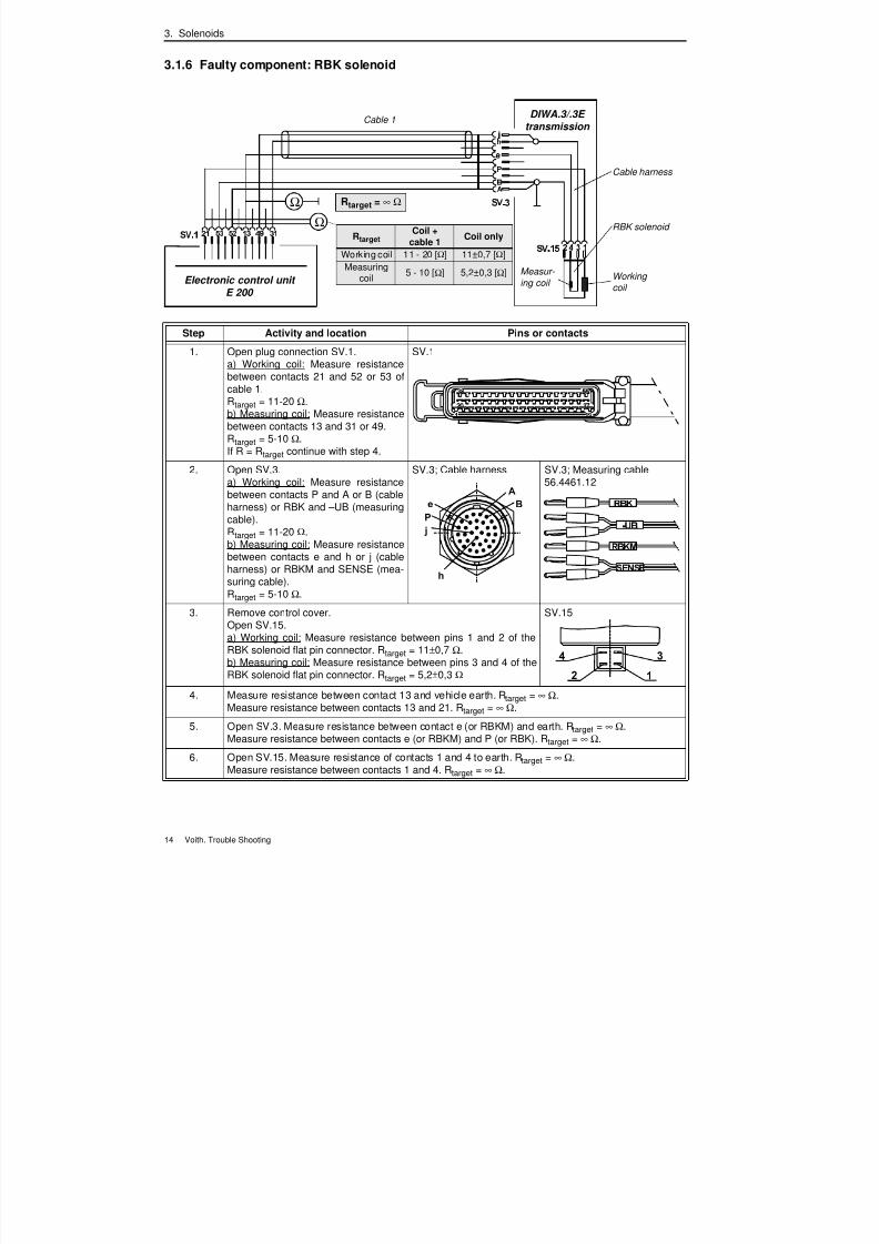
3.1.6 Faulty component: RBK solenoid
Ω
Ω
DIWA.3/.3E
transmission
Cable harness
Electronic control unit
E 200
Cable 1
RBK solenoid
Working
coil
Measur-
ing coil
Rtarget = ∞ Ω
RtargetCoil +
cable 1Coil only
Working coil 11 - 20 [Ω] 11±0,7 [Ω]
Measuringcoil
5 - 10 [Ω] 5,2±0,3 [Ω]
Step Activity and location Pins or contacts
1. Open plug connection SV.1.a) Working coil: Measure resistancebetween contacts 21 and 52 or 53 ofcable 1.Rtarget = 11-20 Ω.b) Measuring coil: Measure resistancebetween contacts 13 and 31 or 49.Rtarget = 5-10 Ω.If R = Rtarget continue with step 4.
SV.1
2. Open SV.3.a) Working coil: Measure resistancebetween contacts P and A or B (cableharness) or RBK and – UB (measuringcable).Rtarget = 11-20 Ω.b) Measuring coil: Measure resistancebetween contacts e and h or j (cableharness) or RBKM and SENSE (mea-suring cable).Rtarget = 5-10 Ω.
SV.3; Cable harness SV.3; Measuring cable56.4461.12
3. Remove control cover.Open SV.15.a) Working coil: Measure resistance between pins 1 and 2 of theRBK solenoid flat pin connector. Rtarget = 11±0,7 Ω.b) Measuring coil: Measure resistance between pins 3 and 4 of theRBK solenoid flat pin connector. Rtarget = 5,2±0,3 Ω
SV.15
4. Measure resistance between contact 13 and vehicle earth. Rtarget = ∞ Ω.Measure resistance between contacts 13 and 21. Rtarget = ∞ Ω.
5. Open SV.3. Measure resistance between contact e (or RBKM) and earth. Rtarget = ∞ Ω.Measure resistance between contacts e (or RBKM) and P (or RBK). Rtarget = ∞ Ω.
6. Open SV.15. Measure resistance of contacts 1 and 4 to earth. Rtarget = ∞ Ω.
Measure resistance between contacts 1 and 4. Rtarget = ∞ Ω.
7/22/2019 Voith Diwa.3 Trouble Shooting
http://slidepdf.com/reader/full/voith-diwa3-trouble-shooting 24/70
3. Solenoids
Voith. Trouble Shooting 15
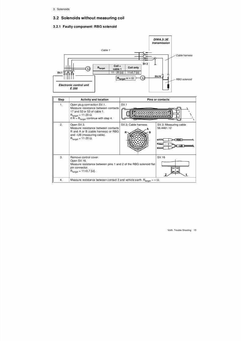
3.2 Solenoids without measuring coil
3.2.1 Faulty component: RBG solenoid
Ω
Ω
DIWA.3/.3E
transmission
Cable harness
Electronic control unit
E 200
Cable 1
RBG solenoid
RtargetCoil +
cable 1Coil only
11 - 20 [Ω] 11±0,7 [Ω]
Rtarget = ∞ Ω
Step Activity and location Pins or contacts
1. Open plug connection SV.1.Measure resistance between contacts17 and 52 or 53 of cable 1.Rtarget = 11-20 Ω.If R = Rtarget continue with step 4.
SV.1
2. Open SV.3.Measure resistance between contactsR and A or B (cable harness) or RBGand – UB (measuring cable).Rtarget = 11-20 Ω.
SV.3; Cable harness SV.3; Measuring cable56.4461.12
3. Remove control cover.Open SV.16.Measure resistance between pins 1 and 2 of the RBG solenoid flat
pin connector.Rtarget = 11±0,7 [Ω].
SV.16
4. Measure resistance between contact 2 and vehicle earth. Rtarget = ∞ Ω.
7/22/2019 Voith Diwa.3 Trouble Shooting
http://slidepdf.com/reader/full/voith-diwa3-trouble-shooting 25/70
3. Solenoids
16 Voith. Trouble Shooting
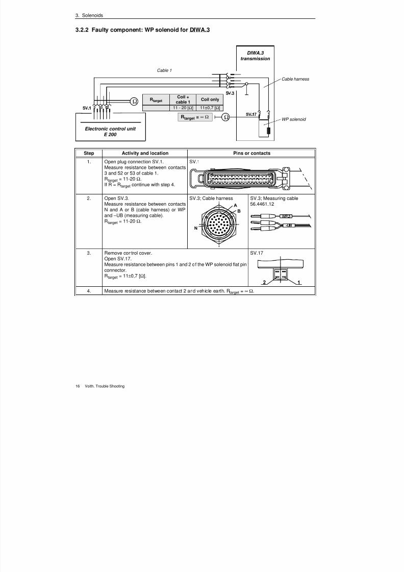
3.2.2 Faulty component: WP solenoid for DIWA.3
Ω
Ω
DIWA.3
transmission
Cable harness
Electronic control unit
E 200
Cable 1
WP solenoid
RtargetCoil +
cable 1Coil only
11 - 20 [Ω] 11±0,7 [Ω]
Rtarget = ∞ Ω
Step Activity and location Pins or contacts
1. Open plug connection SV.1.Measure resistance between contacts3 and 52 or 53 of cable 1.Rtarget = 11-20 Ω.If R = Rtarget continue with step 4.
SV.1
2. Open SV.3.Measure resistance between contacts
N and A or B (cable harness) or WPand – UB (measuring cable).Rtarget = 11-20 Ω.
SV.3; Cable harness SV.3; Measuring cable56.4461.12
3. Remove control cover.Open SV.17.Measure resistance between pins 1 and 2 of the WP solenoid flat pinconnector.Rtarget = 11±0,7 [Ω].
SV.17
4. Measure resistance between contact 2 and vehicle earth. Rtarget = ∞ Ω.
7/22/2019 Voith Diwa.3 Trouble Shooting
http://slidepdf.com/reader/full/voith-diwa3-trouble-shooting 26/70
3. Solenoids
Voith. Trouble Shooting 17
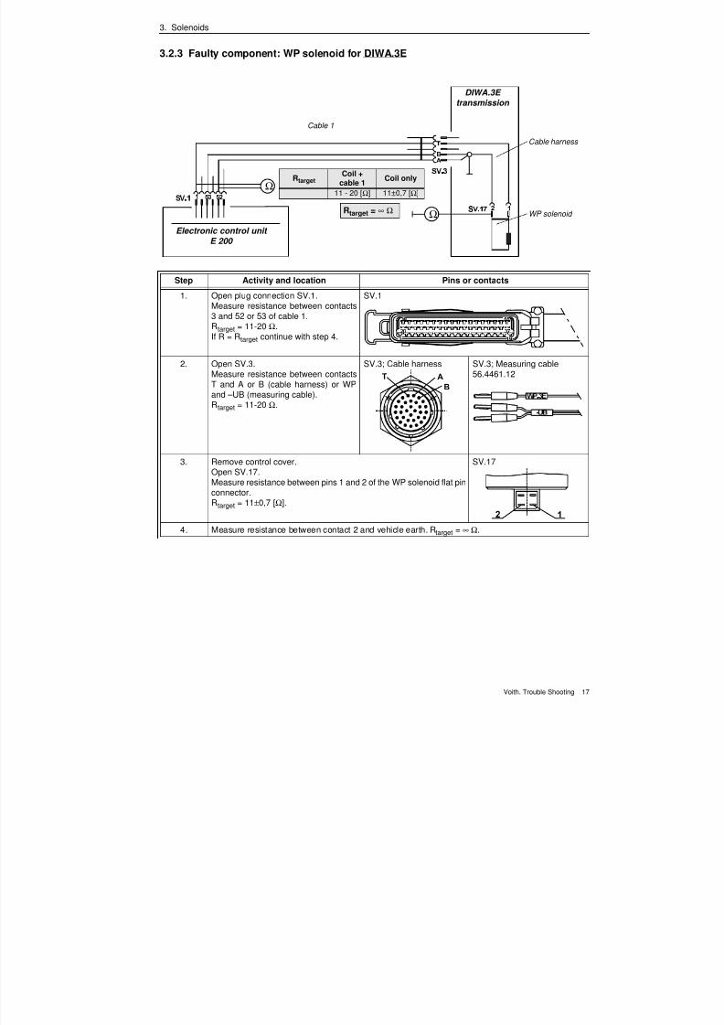
3.2.3 Faulty component: WP solenoid for DIWA.3E
Ω
Ω
DIWA.3E
transmission
Cable harness
Electronic control unit
E 200
Cable 1
WP solenoid
RtargetCoil +
cable 1Coil only
11 - 20 [Ω] 11±0,7 [Ω]
Rtarget = ∞ Ω
Step Activity and location Pins or contacts
1. Open plug connection SV.1.Measure resistance between contacts3 and 52 or 53 of cable 1.Rtarget = 11-20 Ω.If R = Rtarget continue with step 4.
SV.1
2. Open SV.3.Measure resistance between contactsT and A or B (cable harness) or WPand – UB (measuring cable).Rtarget = 11-20 Ω.
SV.3; Cable harness SV.3; Measuring cable56.4461.12
3. Remove control cover.Open SV.17.Measure resistance between pins 1 and 2 of the WP solenoid flat pinconnector.
Rtarget = 11±0,7 [Ω].
SV.17
4. Measure resistance between contact 2 and vehicle earth. Rtarget = ∞ Ω.
7/22/2019 Voith Diwa.3 Trouble Shooting
http://slidepdf.com/reader/full/voith-diwa3-trouble-shooting 27/70
3. Solenoids
18 Voith. Trouble Shooting
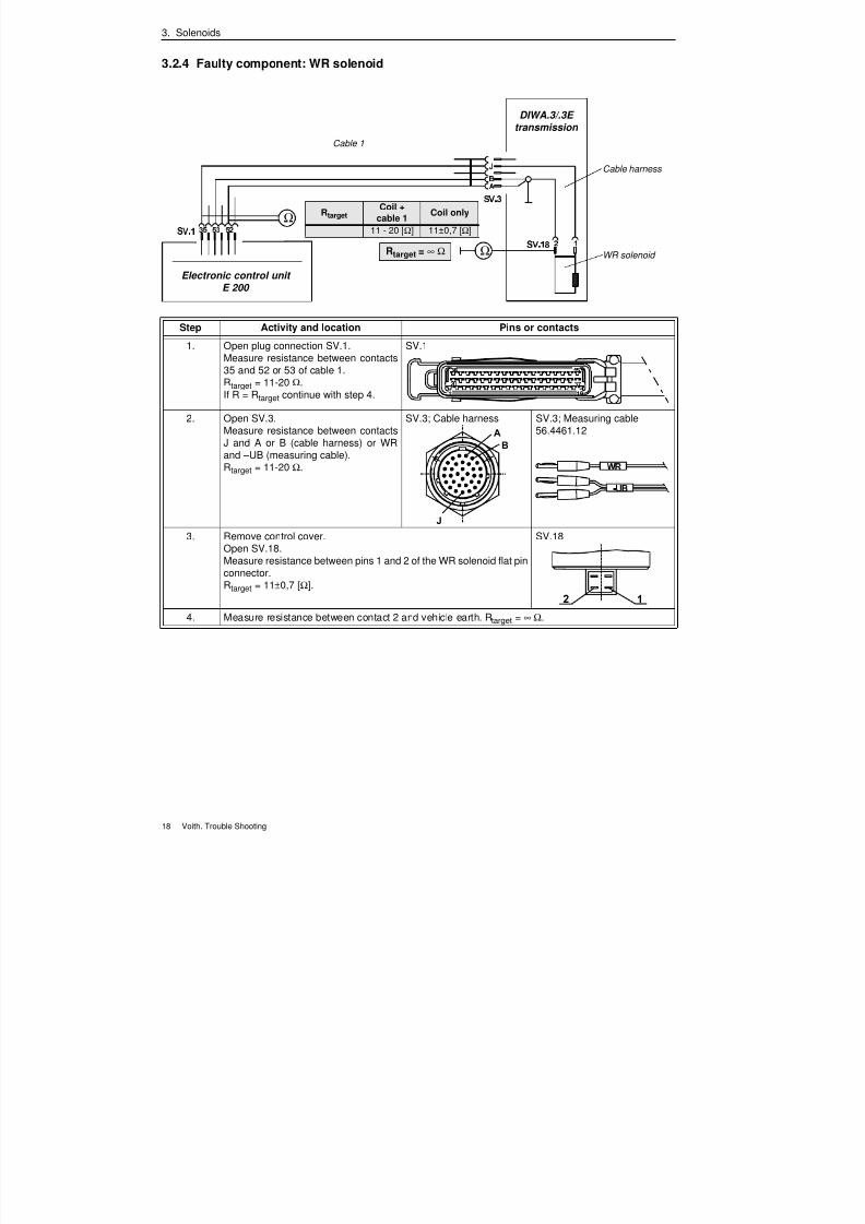
3.2.4 Faulty component: WR solenoid
Ω
Ω
DIWA.3/.3E
transmission
Cable harness
Electronic control unit
E 200
Cable 1
WR solenoid
RtargetCoil +
cable 1Coil only
11 - 20 [Ω] 11±0,7 [Ω]
Rtarget = ∞ Ω
Step Activity and location Pins or contacts
1. Open plug connection SV.1.Measure resistance between contacts35 and 52 or 53 of cable 1.Rtarget = 11-20 Ω.If R = Rtarget continue with step 4.
SV.1
2. Open SV.3.Measure resistance between contactsJ and A or B (cable harness) or WR
and – UB (measuring cable).Rtarget = 11-20 Ω.
SV.3; Cable harness SV.3; Measuring cable56.4461.12
3. Remove control cover.Open SV.18.Measure resistance between pins 1 and 2 of the WR solenoid flat pinconnector.Rtarget = 11±0,7 [Ω].
SV.18
4. Measure resistance between contact 2 and vehicle earth. Rtarget = ∞ Ω.
7/22/2019 Voith Diwa.3 Trouble Shooting
http://slidepdf.com/reader/full/voith-diwa3-trouble-shooting 28/70
7/22/2019 Voith Diwa.3 Trouble Shooting
http://slidepdf.com/reader/full/voith-diwa3-trouble-shooting 29/70
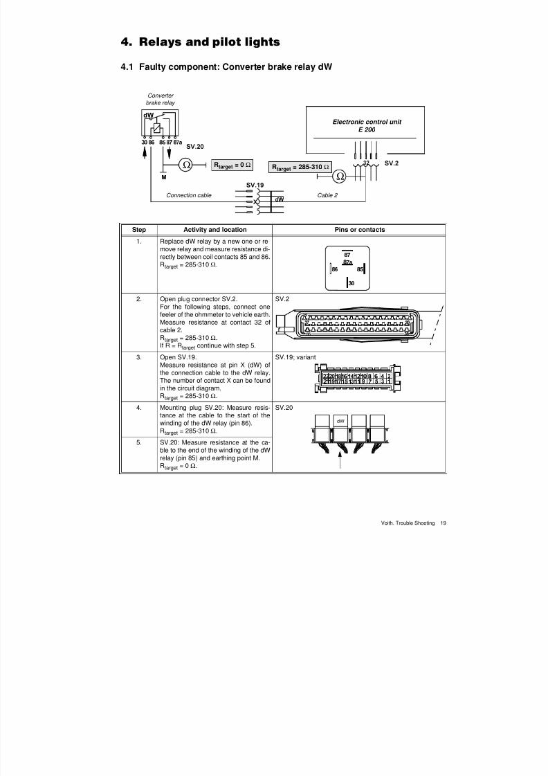
4. Relays and pilot lights
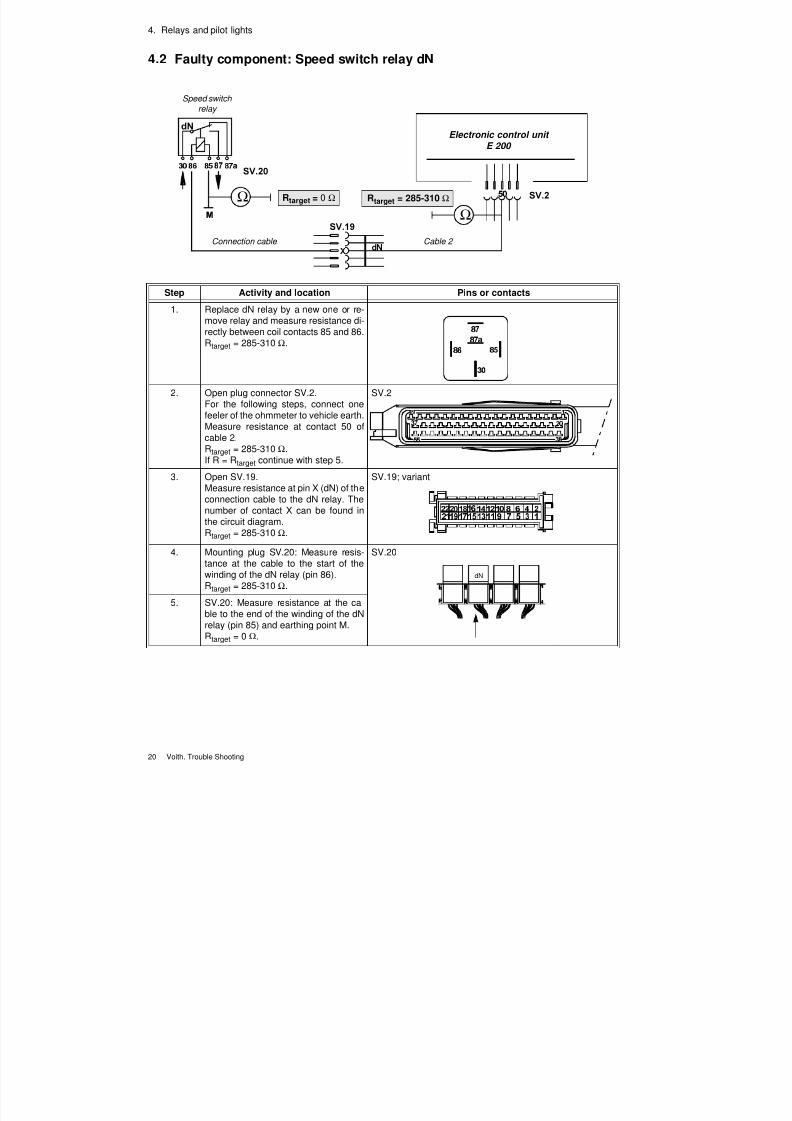
20 Voith. Trouble Shooting
4.2 Faulty component: Speed switch relay dN
Ω
Ω
Electronic control unit
E 200
Cable 2
Speed switch
relay
Connection cable
Rtarget = 0 Ω Rtarget = 285-310 Ω
Step Activity and location Pins or contacts
1. Replace dN relay by a new one or re-move relay and measure resistance di-rectly between coil contacts 85 and 86.Rtarget = 285-310 Ω.
2. Open plug connector SV.2.For the following steps, connect one
feeler of the ohmmeter to vehicle earth.Measure resistance at contact 50 ofcable 2.Rtarget = 285-310 Ω.If R = Rtarget continue with step 5.
SV.2
3. Open SV.19.Measure resistance at pin X (dN) of theconnection cable to the dN relay. Thenumber of contact X can be found inthe circuit diagram.Rtarget = 285-310 Ω.
SV.19; variant
4. Mounting plug SV.20: Measure resis-tance at the cable to the start of thewinding of the dN relay (pin 86).Rtarget = 285-310 Ω.
SV.20
5. SV.20: Measure resistance at the ca-ble to the end of the winding of the dNrelay (pin 85) and earthing point M.Rtarget = 0 Ω.
dN
7/22/2019 Voith Diwa.3 Trouble Shooting
http://slidepdf.com/reader/full/voith-diwa3-trouble-shooting 30/70
4. Relays and pilot lights
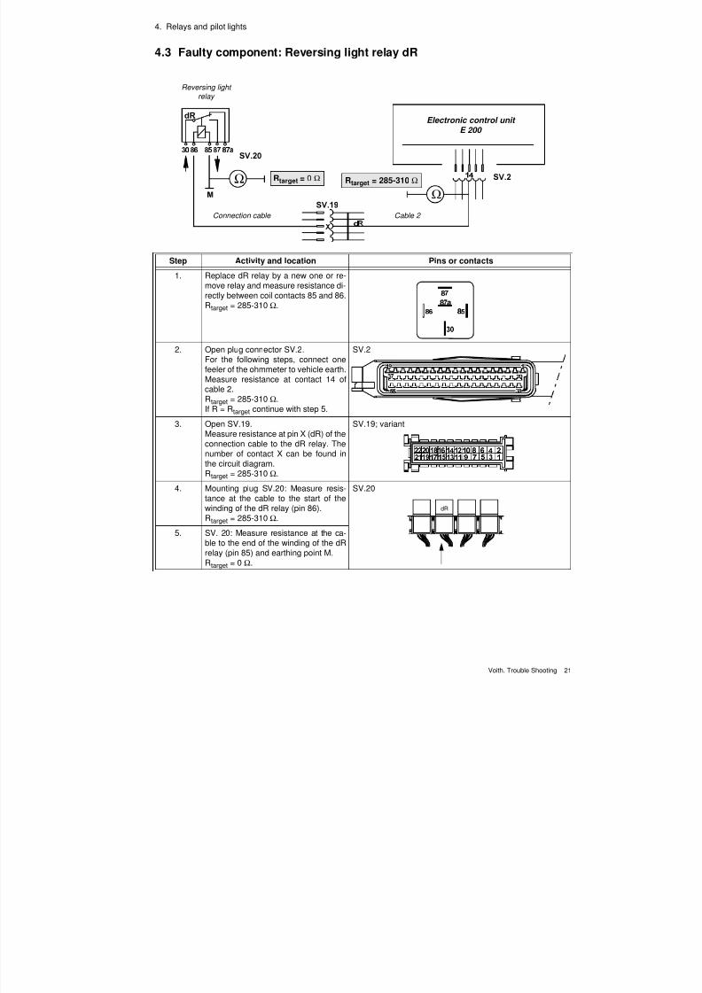
Voith. Trouble Shooting 21
4.3 Faulty component: Reversing light relay dR
Ω
Ω
Electronic control unit E 200
Cable 2
Reversing light
relay
Connection cable
Rtarget = 0 Ω Rtarget = 285-310 Ω
Step Activity and location Pins or contacts
1. Replace dR relay by a new one or re-move relay and measure resistance di-rectly between coil contacts 85 and 86.Rtarget = 285-310 Ω.
2. Open plug connector SV.2.For the following steps, connect one
feeler of the ohmmeter to vehicle earth.Measure resistance at contact 14 ofcable 2.Rtarget = 285-310 Ω.If R = Rtarget continue with step 5.
SV.2
3. Open SV.19.Measure resistance at pin X (dR) of theconnection cable to the dR relay. Thenumber of contact X can be found inthe circuit diagram.Rtarget = 285-310 Ω.
SV.19; variant
4. Mounting plug SV.20: Measure resis-tance at the cable to the start of thewinding of the dR relay (pin 86).Rtarget = 285-310 Ω.
SV.20
5. SV. 20: Measure resistance at the ca-ble to the end of the winding of the dRrelay (pin 85) and earthing point M.Rtarget = 0 Ω.
dR
7/22/2019 Voith Diwa.3 Trouble Shooting
http://slidepdf.com/reader/full/voith-diwa3-trouble-shooting 31/70
4. Relays and pilot lights
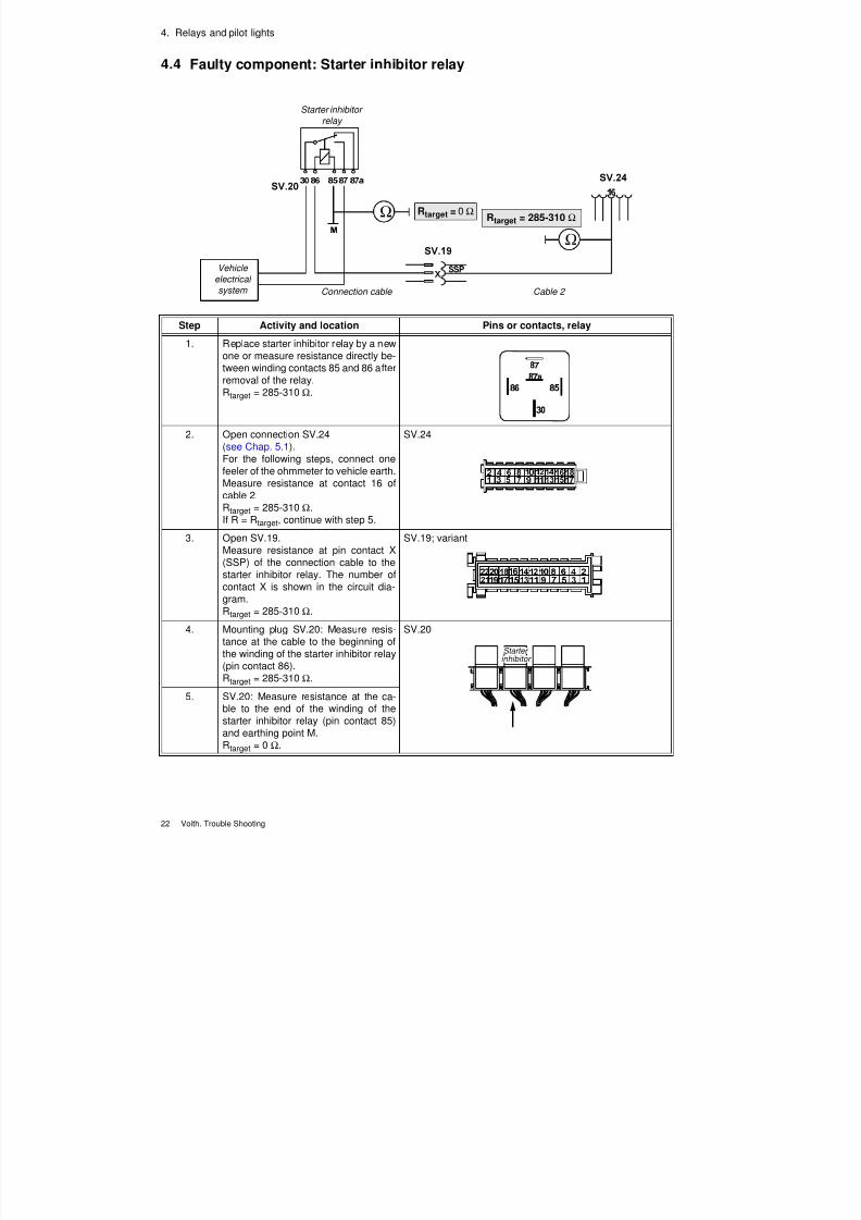
22 Voith. Trouble Shooting
4.4 Faulty component: Starter inhibitor relay
Ω
Ω
Cable 2
Starter inhibitor
relay
Connection cable
Rtarget = 0 ΩRtarget = 285-310 Ω
Vehicle
electrical
system
Step Activity and location Pins or contacts, relay
1. Replace starter inhibitor relay by a newone or measure resistance directly be-tween winding contacts 85 and 86 afterremoval of the relay.Rtarget = 285-310 Ω.
2. Open connection SV.24(see Chap. 5.1).For the following steps, connect onefeeler of the ohmmeter to vehicle earth.Measure resistance at contact 16 ofcable 2.Rtarget = 285-310 Ω.If R = Rtarget, continue with step 5.
SV.24
3. Open SV.19.Measure resistance at pin contact X(SSP) of the connection cable to thestarter inhibitor relay. The number ofcontact X is shown in the circuit dia-
gram.Rtarget = 285-310 Ω.
SV.19; variant
4. Mounting plug SV.20: Measure resis-tance at the cable to the beginning ofthe winding of the starter inhibitor relay(pin contact 86).Rtarget = 285-310 Ω.
SV.20
5. SV.20: Measure resistance at the ca-ble to the end of the winding of thestarter inhibitor relay (pin contact 85)and earthing point M.Rtarget = 0 Ω.
Starterinhibitor
7/22/2019 Voith Diwa.3 Trouble Shooting
http://slidepdf.com/reader/full/voith-diwa3-trouble-shooting 32/70
4. Relays and pilot lights
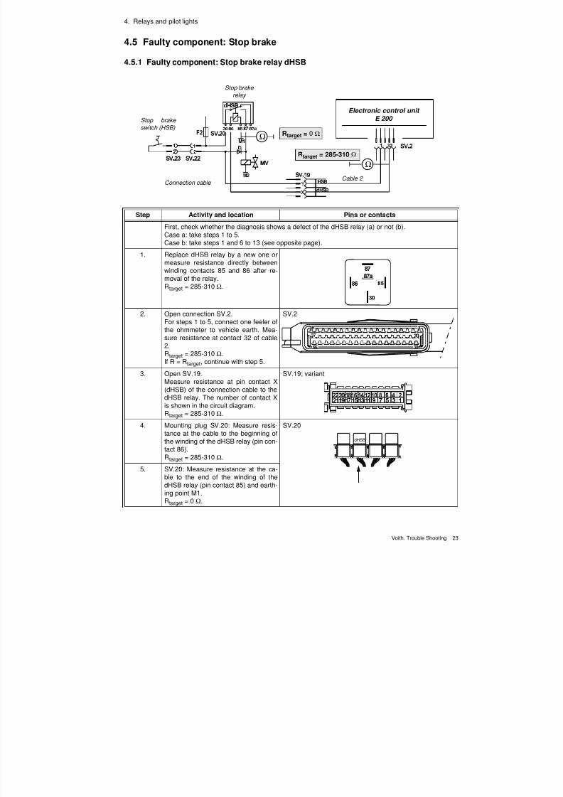
Voith. Trouble Shooting 23
4.5 Faulty component: Stop brake
4.5.1 Faulty component: Stop brake relay dHSB
Ω
Ω
Cable 2
Stop brake
relay
Connection cable
Rtarget = 0 Ω
Rtarget = 285-310 Ω
Stop brake
switch (HSB)
Electronic control unit
E 200
Step Activity and location Pins or contacts
First, check whether the diagnosis shows a defect of the dHSB relay (a) or not (b).Case a: take steps 1 to 5.Case b: take steps 1 and 6 to 13 (see opposite page).
1. Replace dHSB relay by a new one ormeasure resistance directly betweenwinding contacts 85 and 86 after re-moval of the relay.Rtarget = 285-310 Ω.
2. Open connection SV.2.For steps 1 to 5, connect one feeler ofthe ohmmeter to vehicle earth. Mea-sure resistance at contact 32 of cable2.Rtarget = 285-310 Ω.If R = Rtarget, continue with step 5.
SV.2
3. Open SV.19.Measure resistance at pin contact X(dHSB) of the connection cable to thedHSB relay. The number of contact Xis shown in the circuit diagram.Rtarget = 285-310 Ω.
SV.19; variant
4. Mounting plug SV.20: Measure resis-tance at the cable to the beginning ofthe winding of the dHSB relay (pin con-tact 86).Rtarget = 285-310 Ω.
SV.20
5. SV.20: Measure resistance at the ca-ble to the end of the winding of thedHSB relay (pin contact 85) and earth-
ing point M1.Rtarget = 0 Ω.
dHSB
7/22/2019 Voith Diwa.3 Trouble Shooting
http://slidepdf.com/reader/full/voith-diwa3-trouble-shooting 33/70
7/22/2019 Voith Diwa.3 Trouble Shooting
http://slidepdf.com/reader/full/voith-diwa3-trouble-shooting 34/70
4. Relays and pilot lights
Voith. Trouble Shooting 25
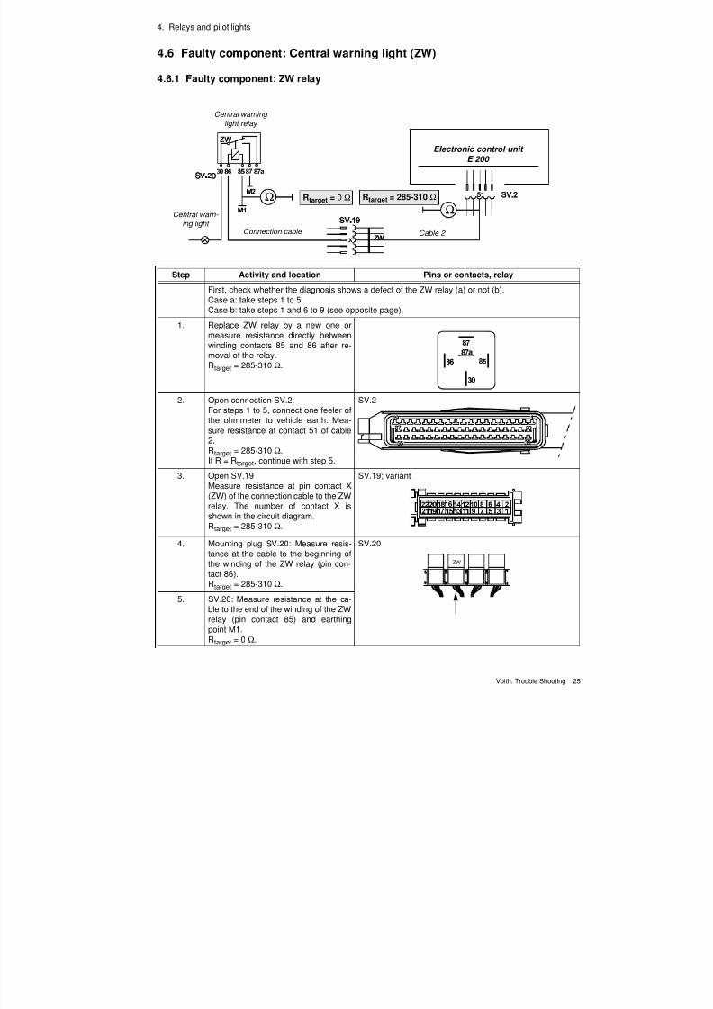
4.6 Faulty component: Central warning light (ZW)
4.6.1 Faulty component: ZW relay
Ω
Ω
Cable 2
Central warning
light relay
Connection cable
Rtarget = 0 Ω Rtarget = 285-310 Ω
Central warn- ing light
Electronic control unit
E 200
Step Activity and location Pins or contacts, relay
First, check whether the diagnosis shows a defect of the ZW relay (a) or not (b).Case a: take steps 1 to 5.Case b: take steps 1 and 6 to 9 (see opposite page).
1. Replace ZW relay by a new one ormeasure resistance directly betweenwinding contacts 85 and 86 after re-moval of the relay.Rtarget = 285-310 Ω.
2. Open connection SV.2.For steps 1 to 5, connect one feeler ofthe ohmmeter to vehicle earth. Mea-sure resistance at contact 51 of cable2.Rtarget = 285-310 Ω.If R = Rtarget, continue with step 5.
SV.2
3. Open SV.19Measure resistance at pin contact X
(ZW) of the connection cable to the ZWrelay. The number of contact X isshown in the circuit diagram.Rtarget = 285-310 Ω.
SV.19; variant
4. Mounting plug SV.20: Measure resis-tance at the cable to the beginning ofthe winding of the ZW relay (pin con-tact 86).Rtarget = 285-310 Ω.
SV.20
5. SV.20: Measure resistance at the ca-ble to the end of the winding of the ZW
relay (pin contact 85) and earthingpoint M1.Rtarget = 0 Ω.
ZW
7/22/2019 Voith Diwa.3 Trouble Shooting
http://slidepdf.com/reader/full/voith-diwa3-trouble-shooting 35/70
7/22/2019 Voith Diwa.3 Trouble Shooting
http://slidepdf.com/reader/full/voith-diwa3-trouble-shooting 36/70
4. Relays and pilot lights
Voith. Trouble Shooting 27
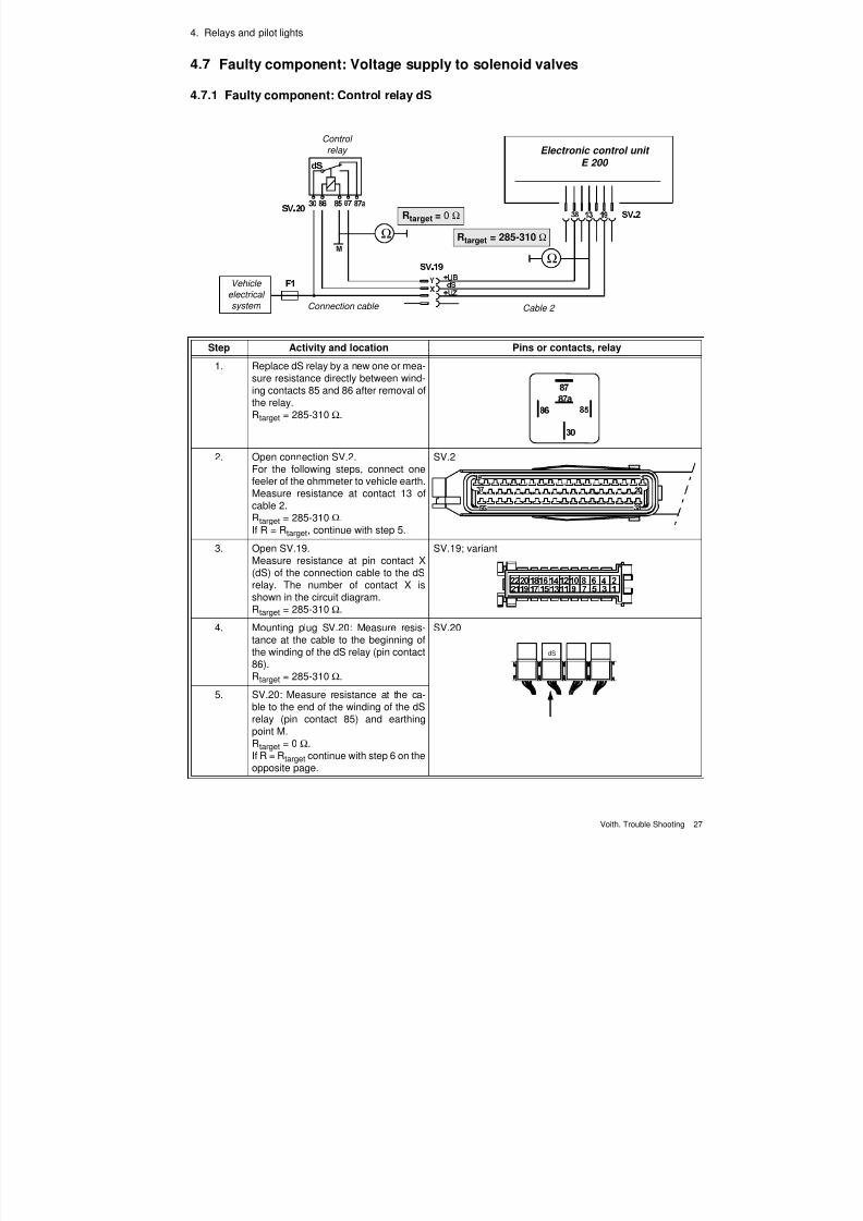
4.7 Faulty component: Voltage supply to solenoid valves
4.7.1 Faulty component: Control relay dS
Ω
Ω
Cable 2
Control
relay
Connection cable
Rtarget = 0 Ω
Rtarget = 285-310 Ω
Vehicle
electrical
system
Electronic control unit E 200
Step Activity and location Pins or contacts, relay
1. Replace dS relay by a new one or mea-sure resistance directly between wind-ing contacts 85 and 86 after removal ofthe relay.Rtarget = 285-310 Ω.
2. Open connection SV.2.For the following steps, connect onefeeler of the ohmmeter to vehicle earth.Measure resistance at contact 13 ofcable 2.Rtarget = 285-310 Ω.If R = Rtarget, continue with step 5.
SV.2
3. Open SV.19.Measure resistance at pin contact X(dS) of the connection cable to the dSrelay. The number of contact X isshown in the circuit diagram.Rtarget = 285-310 Ω.
SV.19; variant
4. Mounting plug SV.20: Measure resis-tance at the cable to the beginning ofthe winding of the dS relay (pin contact86).Rtarget = 285-310 Ω.
SV.20
5. SV.20: Measure resistance at the ca-ble to the end of the winding of the dSrelay (pin contact 85) and earthingpoint M.Rtarget = 0 Ω.
If R = Rtarget continue with step 6 on theopposite page.
dS
7/22/2019 Voith Diwa.3 Trouble Shooting
http://slidepdf.com/reader/full/voith-diwa3-trouble-shooting 37/70
7/22/2019 Voith Diwa.3 Trouble Shooting
http://slidepdf.com/reader/full/voith-diwa3-trouble-shooting 38/70
Voith. Trouble Shooting 29
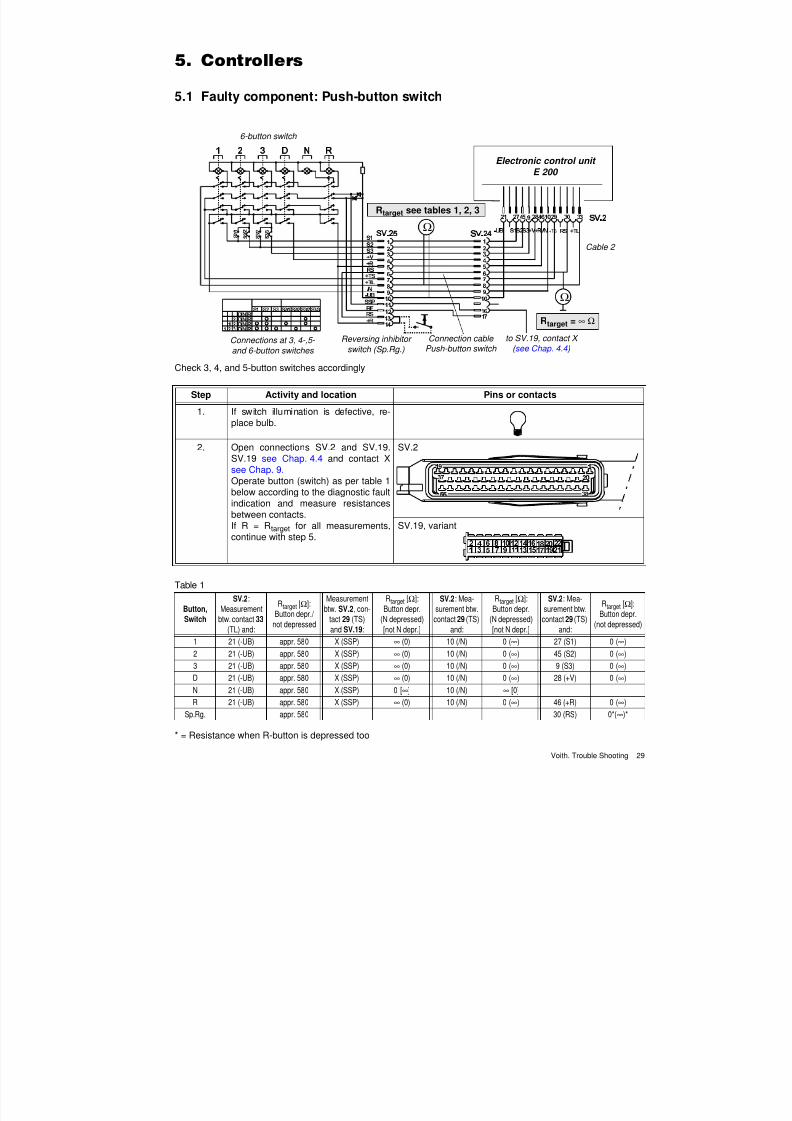
5.1 Faulty component: Push-button switch
Check 3, 4, and 5-button switches accordingly
* = Resistance when R-button is depressed too
+TS
Ω
Ω
Electronic control unit
E 200
6-button switch
Rtarget = ∞ Ω
Rtarget see tables 1, 2, 3
Connections at 3, 4-,5-
and 6-button switches
Reversing inhibitor
switch (Sp.Rg.)
Connection cable Push-button switch
to SV.19, contact X
( see Chap. 4.4 )
Cable 2
Step Activity and location Pins or contacts
1. If switch illumination is defective, re-place bulb.
2. Open connections SV.2 and SV.19.SV.19 see Chap. 4.4 and contact Xsee Chap. 9.Operate button (switch) as per table 1below according to the diagnostic faultindication and measure resistancesbetween contacts.If R = Rtarget for all measurements,continue with step 5.
SV.2
SV.19, variant
Table 1
Button,
Switch
SV.2:
Measurement
btw. contact 33
(TL) and:
Rtarget [Ω]:
Button depr./
not depressed
Measurement
btw. SV.2, con-
tact 29 (TS)
and SV.19:
Rtarget [Ω]:
Button depr.
(N depressed)
[not N depr.]
SV.2: Mea-
surement btw.
contact 29 (TS)
and:
Rtarget [Ω]:
Button depr.
(N depressed)
[not N depr.]
SV.2: Mea-
surement btw.
contact 29 (TS)
and:
Rtarget [Ω]:
Button depr.
(not depressed)
1 21 (-UB) appr. 580 X (SSP) ∞ (0) 10 (/N) 0 (∞) 27 (S1) 0 (∞)
2 21 (-UB) appr. 580 X (SSP) ∞ (0) 10 (/N) 0 (∞) 45 (S2) 0 (∞)
3 21 (-UB) appr. 580 X (SSP) ∞ (0) 10 (/N) 0 (∞) 9 (S3) 0 (∞)
D 21 (-UB) appr. 580 X (SSP) ∞ (0) 10 (/N) 0 (∞) 28 (+V) 0 (∞)
N 21 (-UB) appr. 580 X (SSP) 0 [∞] 10 (/N) ∞ [0]R 21 (-UB) appr. 580 X (SSP) ∞ (0) 10 (/N) 0 (∞) 46 (+R) 0 (∞)
Sp.Rg. appr. 580 30 (RS) 0*(∞)*
7/22/2019 Voith Diwa.3 Trouble Shooting
http://slidepdf.com/reader/full/voith-diwa3-trouble-shooting 39/70
5. Controllers
30 Voith. Trouble Shooting
* = Resistance when R-button is depressed too
* = Resistance when R-button is depressed too
Step Activity and location Pins or contacts
3. Open SV.24.Operate button (switch) as per table 2below according to the diagnostic faultindication and measure resistances
between contacts.
SV.24
Table 2
Button,
Switch
Measurement
btw. contact
8 (TL) and:
Rtarget [Ω]:
Button depr./
not depressed
Measurement
btw. contact
7 (TS) and:
Rtarget [Ω]:
Button depr.
(N depressed)
[not N depr.]
Measurement
btw. contact
7 (TS) and:
Rtarget [Ω]:
Button depr.
(N depressed)
[not N depr.]
Measurement
btw. contact
7 (TS) and:
Rtarget [Ω]:
Button depr.
(not depressed)
1 10 (-UB) appr. 580 16 (SSP) ∞ (0) 9 (/N) 0 (∞) 1 (S1) 0 (∞)
2 10 (-UB) appr. 580 16 (SSP) ∞ (0) 9 (/N) 0 (∞) 2 (S2) 0 (∞)
3 10 (-UB) appr. 580 16 (SSP) ∞ (0) 9 (/N) 0 (∞) 3 (S3) 0 (∞)
D 10 (-UB) appr. 580 16 (SSP) ∞ (0) 9 (/N) 0 (∞) 4 (+V) 0 (∞)
N 10 (-UB) appr. 580 16 (SSP) 0 [∞] 9 (/N) ∞ [0]R 10 (-UB) appr. 580 16 (SSP) ∞ (0) 9 (/N) 0 (∞) 5 (+R) 0 (∞)
Sp.Rg. 6 (RS) 0* (∞)*
Step Activity and location Pins or contacts
4. Open SV.25.Operate button (switch) as per table 3below according to the diagnostic faultindication and measure resistances
between contacts.
SV.25
Table 3
Button,
Switch
Measurement
btw. contact
8 (TL) and:
Rtarget [Ω]:
Button depr./
not depressed
Measurement
btw. contact
7 (TS) and:
Rtarget [Ω]:
Button depr.
(N depressed)
[not N depr.]
Measurement
btw. contact
7 (TS) and:
Rtarget [Ω]:
Button depr.
(N depressed)
[not N depr.]
Measurement
btw. contact
7 (TS) and:
Rtarget [Ω]:
Button depr.
(not depressed)
1 10 (-UB) appr. 580 11 (SSP) ∞ (0) 9 (/N) 0 (∞) 1 (S1) 0 (∞)
2 10 (-UB) appr. 580 11 (SSP) ∞ (0) 9 (/N) 0 (∞) 2 (S2) 0 (∞)
3 10 (-UB) appr. 580 11 (SSP) ∞ (0) 9 (/N) 0 (∞) 3 (S3) 0 (∞)
D 10 (-UB) appr. 580 11 (SSP) ∞ (0) 9 (/N) 0 (∞) 4 (+V) 0 (∞)
N 10 (-UB) appr. 580 11 (SSP) 0 [∞] 9 (/N) ∞ [0]
R 10 (-UB) appr. 580 11 (SSP) ∞ (0) 9 (/N) 0 (∞) 5 (+R) 0 (∞)
Sp.Rg. 6 (RS) 0* (∞*)
Step Activity
5. Measure resistance to earth of SV.2, contacts 9, 10, 21, 27, 28, 29, 30, 33, 45, 46and SV.19, contact X.Rtarget = ∞ Ω.
6. Open SV.24. Measure resistance of contacts 1-10 and 16 to earth. Rtarget = ∞ Ω.
7/22/2019 Voith Diwa.3 Trouble Shooting
http://slidepdf.com/reader/full/voith-diwa3-trouble-shooting 40/70
5. Controllers
Voith. Trouble Shooting 31
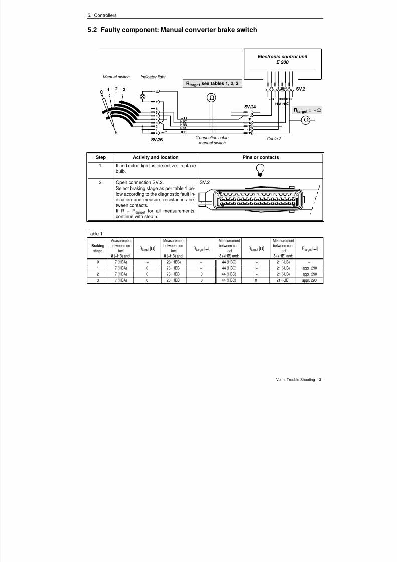
5.2 Faulty component: Manual converter brake switch
Step Activity and location Pins or contacts
1. If indicator light is defective, replacebulb.
2. Open connection SV.2.Select braking stage as per table 1 be-low according to the diagnostic fault in-dication and measure resistances be-tween contacts.If R = Rtarget for all measurements,continue with step 5.
SV.2
Table 1
Braking
stage
Measurement
between con-
tact
8 (+HB) and:
Rtarget [Ω]
Measurement
between con-
tact
8 (+HB) and:
Rtarget [Ω]
Measurement
between con-
tact
8 (+HB) and:
Rtarget [Ω]
Measurement
between con-
tact
8 (+HB) and:
Rtarget [Ω]
0 7 (HBA) ∞ 26 (HBB) ∞ 44 (HBC) ∞ 21 (-UB) ∞
1 7 (HBA) 0 26 (HBB) ∞ 44 (HBC) ∞ 21 (-UB) appr. 290
2 7 (HBA) 0 26 (HBB) 0 44 (HBC) ∞ 21 (-UB) appr. 290
3 7 (HBA) 0 26 (HBB) 0 44 (HBC) 0 21 (-UB) appr. 290
Ω
Ω
Electronic control unit
E 200
Manual switch
Rtarget = ∞ Ω
Rtarget see tables 1, 2, 3
Connection cablemanual switch
Cable 2
Indicator light
7/22/2019 Voith Diwa.3 Trouble Shooting
http://slidepdf.com/reader/full/voith-diwa3-trouble-shooting 41/70
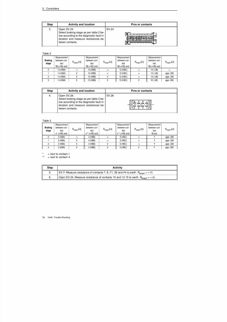
5. Controllers
32 Voith. Trouble Shooting
* = next to contact 1** = next to contact 4
Step Activity and location Pins or contacts
3. Open SV.24.Select braking stage as per table 2 be-low according to the diagnostic fault in-
dication and measure resistances be-tween contacts.
SV.24
Table 2
Braking
stage
Measurement
between con-
tact
15 (+HB) and:
Rtarget [Ω]
Measurement
between con-
tact
15 (+HB) and:
Rtarget [Ω]
Measurement
between con-
tact
15 (+HB) and:
Rtarget [Ω]
Measurement
between con-
tact
15 (+HB) and:
Rtarget [Ω]
0 14 (HBA) ∞ 13 (HBB) ∞ 12 (HBC) ∞ 10 (-UB) ∞
1 14 (HBA) 0 13 (HBB) ∞ 12 (HBC) ∞ 10 (-UB) appr. 290
2 14 (HBA) 0 13 (HBB) 0 12 (HBC) ∞ 10 (-UB) appr. 290
3 14 (HBA) 0 13 (HBB) 0 12 (HBC) 0 10 (-UB) appr. 290
Step Activity and location Pins or contacts
4. Open SV.26.Select braking stage as per table 3 be-low according to the diagnostic fault in-dication and measure resistances be-tween contacts.
SV.26
Table 3
Braking
stage
Measurement
between con-
tact
+* (+HB) and:
Rtarget [Ω]
Measurement
between con-
tact
+** (+HB) and:
Rtarget [Ω]
Measurement
between con-
tact
+** (+HB) and:
Rtarget [Ω]
Measurement
between con-
tact
X and:
Rtarget [Ω]
0 3 (HBA) ∞ 4 (HBB) ∞ 5 (HBC) ∞ Y appr. 290
1 3 (HBA) 0 4 (HBB) ∞ 5 (HBC) ∞ Y appr. 290
2 3 (HBA) 0 4 (HBB) 0 5 (HBC) ∞ Y appr. 290
3 3 (HBA) 0 4 (HBB) 0 5 (HBC) 0 Y appr. 290
Step Activity
5. SV.2: Measure resistance of contacts 7, 8, 21, 26 and 44 to earth. Rtarget = ∞ Ω.
6. Open SV.24. Measure resistance of contacts 10 and 12-15 to earth. Rtarget = ∞ Ω.
7/22/2019 Voith Diwa.3 Trouble Shooting
http://slidepdf.com/reader/full/voith-diwa3-trouble-shooting 42/70
7/22/2019 Voith Diwa.3 Trouble Shooting
http://slidepdf.com/reader/full/voith-diwa3-trouble-shooting 43/70
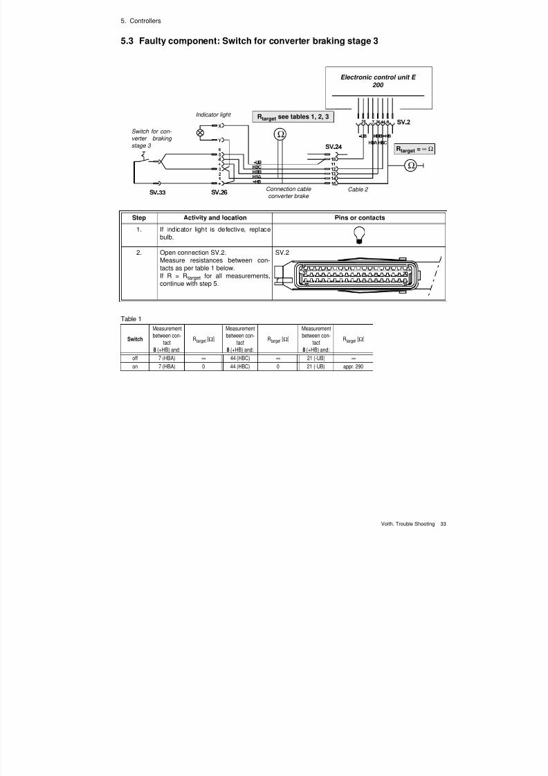
5. Controllers
34 Voith. Trouble Shooting
* * = next to contact 1** = next to contact 4
Step Activity and location Pins or contacts
3. Open SV.24.Measure resistances between con-tacts as per table 2 below.
SV.24
Table 2
Switch
Measurement
between con-
tact
15 (+HB) and:
Rtarget [Ω]
Measurement
between con-
tact
15 (+HB) and:
Rtarget [Ω]
Measurement
between con-
tact
15 (+HB) and:
Rtarget [Ω]
off 14 (HBA) ∞ 12 (HBC) ∞ 10 (-UB) ∞
on 14 (HBA) 0 12 (HBC) 0 10 (-UB) appr. 290
Step Activity and location Pins or contacts
4. Open SV.26.Measure resistances between con-tacts as per table 3 below.
SV.26
Table 3
Switch
Measurement
between con-
tact
+* (+HB) and:
Rtarget [Ω]
Measurement
between con-
tact
+** (+HB) and:
Rtarget [Ω]
Measurement
between con-
tact
X and:
Rtarget [Ω]
off 3 (HBA) ∞ 5 (HBC) ∞ Y appr. 290
on 3 (HBA) 0 5 (HBC) 0 Y appr. 290
Step Activity
5. SV.2: Measure resistance of contacts 7, 8, 21, and 44 to vehicle earth. Rtarget = ∞ Ω.
6. Open SV.24. Measure resistance of contacts 10 and 12, 14 and 15 to earth. Rtarget = ∞ Ω.
7/22/2019 Voith Diwa.3 Trouble Shooting
http://slidepdf.com/reader/full/voith-diwa3-trouble-shooting 44/70
7/22/2019 Voith Diwa.3 Trouble Shooting
http://slidepdf.com/reader/full/voith-diwa3-trouble-shooting 45/70
5. Controllers
36 Voith. Trouble Shooting
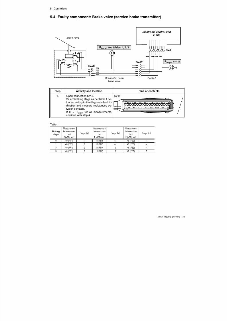
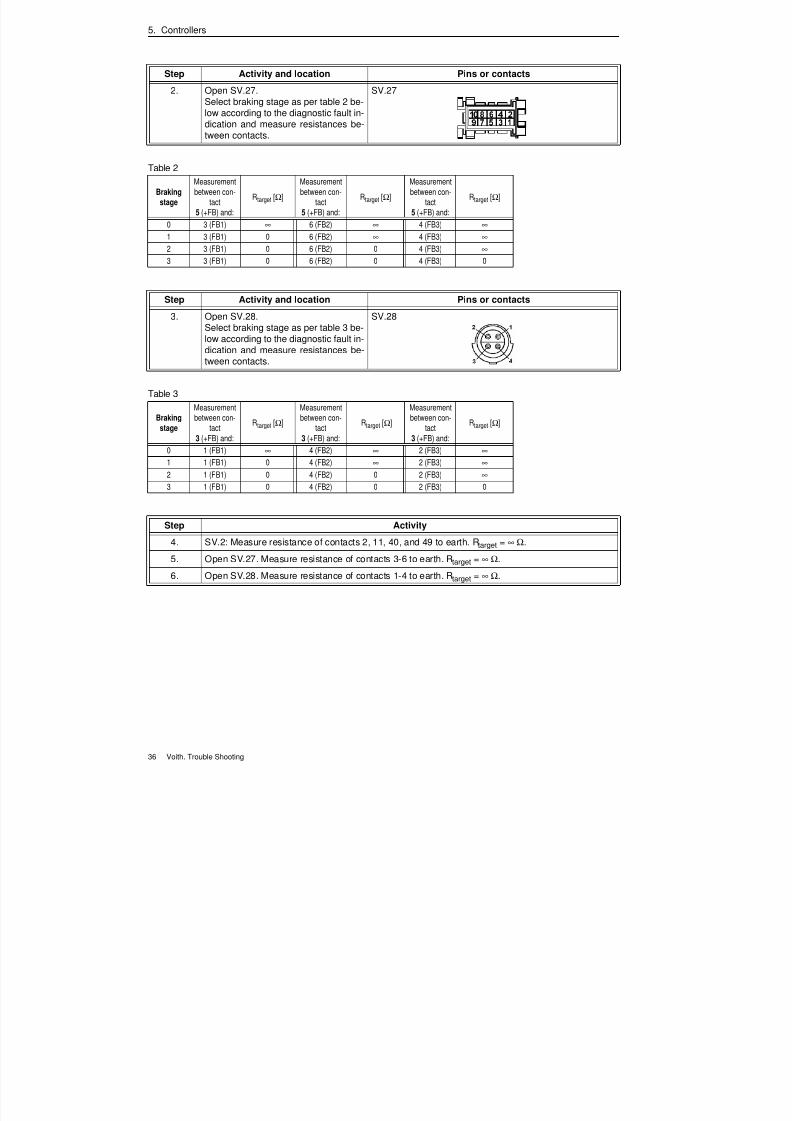
Step Activity and location Pins or contacts
2. Open SV.27.Select braking stage as per table 2 be-low according to the diagnostic fault in-dication and measure resistances be-
tween contacts.
SV.27
Table 2
Braking
stage
Measurement
between con-
tact
5 (+FB) and:
Rtarget [Ω]
Measurement
between con-
tact
5 (+FB) and:
Rtarget [Ω]
Measurement
between con-
tact
5 (+FB) and:
Rtarget [Ω]
0 3 (FB1) ∞ 6 (FB2) ∞ 4 (FB3) ∞
1 3 (FB1) 0 6 (FB2) ∞ 4 (FB3) ∞
2 3 (FB1) 0 6 (FB2) 0 4 (FB3) ∞
3 3 (FB1) 0 6 (FB2) 0 4 (FB3) 0
Step Activity and location Pins or contacts
3. Open SV.28.Select braking stage as per table 3 be-low according to the diagnostic fault in-dication and measure resistances be-tween contacts.
SV.28
Table 3
Brakingstage
Measurement
between con-tact
3 (+FB) and:
Rtarget [Ω]
Measurement
between con-tact
3 (+FB) and:
Rtarget [Ω]
Measurement
between con-tact
3 (+FB) and:
Rtarget [Ω]
0 1 (FB1) ∞ 4 (FB2) ∞ 2 (FB3) ∞
1 1 (FB1) 0 4 (FB2) ∞ 2 (FB3) ∞
2 1 (FB1) 0 4 (FB2) 0 2 (FB3) ∞
3 1 (FB1) 0 4 (FB2) 0 2 (FB3) 0
Step Activity
4. SV.2: Measure resistance of contacts 2, 11, 40, and 49 to earth. Rtarget = ∞ Ω.
5. Open SV.27. Measure resistance of contacts 3-6 to earth. Rtarget = ∞ Ω.
6. Open SV.28. Measure resistance of contacts 1-4 to earth. Rtarget = ∞ Ω.
7/22/2019 Voith Diwa.3 Trouble Shooting
http://slidepdf.com/reader/full/voith-diwa3-trouble-shooting 46/70
5. Controllers
Voith. Trouble Shooting 37
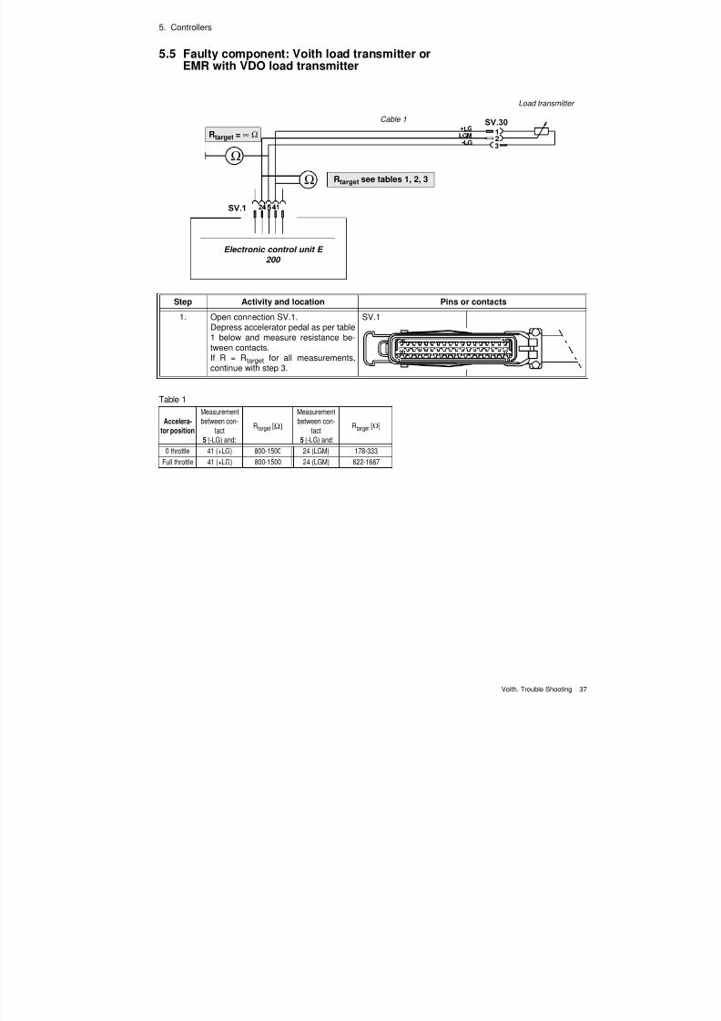
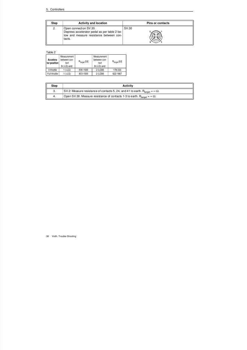
5.5 Faulty component: Voith load transmitter orEMR with VDO load transmitter
Ω
Ω
Electronic control unit E200
Rtarget = ∞ Ω
Rtarget see tables 1, 2, 3
Cable 1
Load transmitter
Step Activity and location Pins or contacts
1. Open connection SV.1.Depress accelerator pedal as per table1 below and measure resistance be-tween contacts.If R = Rtarget for all measurements,continue with step 3.
SV.1
Table 1
Accelera-
tor position
Measurement
between con-
tact
5 (-LG) and:
Rtarget [Ω]
Measurement
between con-
tact
5 (-LG) and:
Rtarget [Ω]
0 throttle 41 (+LG) 800-1500 24 (LGM) 178-333
Full throttle 41 (+LG) 800-1500 24 (LGM) 622-1667
7/22/2019 Voith Diwa.3 Trouble Shooting
http://slidepdf.com/reader/full/voith-diwa3-trouble-shooting 47/70
7/22/2019 Voith Diwa.3 Trouble Shooting
http://slidepdf.com/reader/full/voith-diwa3-trouble-shooting 48/70
5. Controllers
Voith. Trouble Shooting 39
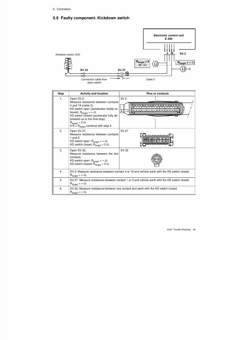
5.6 Faulty component: Kickdown switch
Ω
Ω
Electronic control unit
E 200
Rtarget = ∞ ΩRtarget = 0or ∞Ω
Cable 2
Kickdown switch (KD)
Connection cable Kick-
down switch
Step Activity and location Pins or contacts
1. Open SV.2.Measure resistance between contacts4 and 19 (cable 2).KD switch open (accelerator totally re-lieved): Rtarget = ∞ Ω.KD switch closed (accelerator fully de-pressed up to the final stop):Rtarget = 0 Ω.
If R = Rtarget continue with step 4.
SV.2
2. Open SV.27.Measure resistance between contacts1 and 2.KD switch open: Rtarget = ∞ Ω.KD switch closed: Rtarget = 0 Ω.
SV.27
3. Open SV.32.Measure resistance between the twocontacts.KD switch open: Rtarget = ∞ Ω.KD switch closed: Rtarget = 0 Ω.
SV.32
4. SV.2: Measure resistance between contact 4 or 19 and vehicle earth with the KD switch closed.Rtarget = ∞ Ω.
5. SV.27: Measure resistance between contact 1 or 2 and vehicle earth with the KD switch closed.Rtarget = ∞ Ω.
6. SV.32: Measure resistance between one contact and earth with the KD switch closed.Rtarget = ∞ Ω.

7/22/2019 Voith Diwa.3 Trouble Shooting
http://slidepdf.com/reader/full/voith-diwa3-trouble-shooting 49/70
5. Controllers
40 Voith. Trouble Shooting
7/22/2019 Voith Diwa.3 Trouble Shooting
http://slidepdf.com/reader/full/voith-diwa3-trouble-shooting 50/70
Voith. Trouble Shooting 41
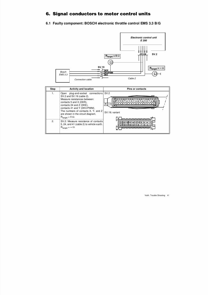
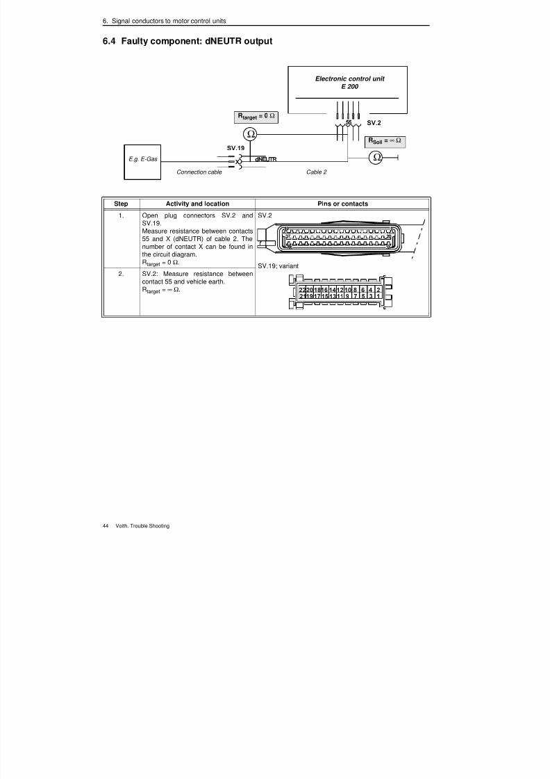
6.1 Faulty component: BOSCH electronic throttle control EMS 3.3 B/G
Ω
Ω
Electronic control unit
E 200
Rtarget = ∞ Ω
Rtarget = 0 Ω
Cable 2
BoschEMS 3.3
Connection cable
Step Activity and location Pins or contacts
1. Open plug-and-socket connectionsSV.2 and SV.19 (cable 2).Measure resistances between:contacts 5 and X (DKR),contacts 24 and Z (DKE),contacts 41 and Y (DKV/PWM).The numbers of contacts X, Y, and Zare shown in the circuit diagram.Rtarget = 0 Ω.
SV.2
SV.19; variant
2. SV.2: Measure resistance of contacts5, 24, and 41 (cable 2) to vehicle earth.Rtarget = ∞ Ω.
7/22/2019 Voith Diwa.3 Trouble Shooting
http://slidepdf.com/reader/full/voith-diwa3-trouble-shooting 51/70
6. Signal conductors to motor control units
42 Voith. Trouble Shooting
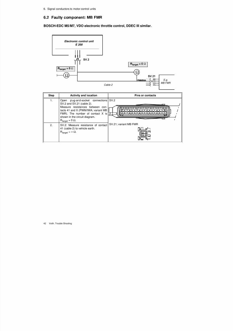
6.2 Faulty component: MB FMR
BOSCH-EDC M5/M7, VDO electronic throttle control, DDEC III similar.
Step Activity and location Pins or contacts
1. Open plug-and-socket connectionsSV.2 and SV.21 (cable 2).Measure resistances between con-tacts 41 and X (PWM/IWA; variant MBFMR). The number of contact X isshown in the circuit diagram.Rtarget = 0 Ω.
SV.2
SV.21; variant MB FMR2. SV.2: Measure resistance of contact41 (cable 2) to vehicle earth.Rtarget = ∞ Ω.
Ω
Ω
Electronic control unitE 200
Rtarget = 0 Ω
Cable 2
E.g.
MB FMR
Rtarget = 0 Ω
7/22/2019 Voith Diwa.3 Trouble Shooting
http://slidepdf.com/reader/full/voith-diwa3-trouble-shooting 52/70
6. Signal conductors to motor control units
Voith. Trouble Shooting 43
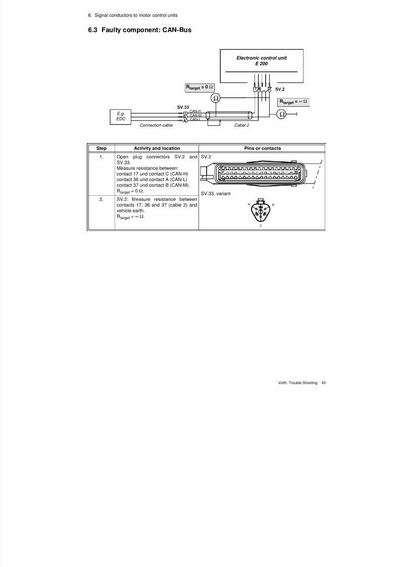
6.3 Faulty component: CAN-Bus
Ω
Ω
CAN-HCAN-MCAN-L
Electronic control unit
E 200
Rtarget = 0 Ω
Cabel 2
Rtarget = ∞ Ω
Connection cable
E.g.
EDC
Step Activity and location Pins or contacts
1. Open plug connectors SV.2 andSV.33.Measure resistance between:contact 17 und contact C (CAN-H)contact 36 und contact A (CAN-L)contact 37 und contact B (CAN-M).Rtarget = 0 Ω.
SV.2
SV.33, variant
2. SV.2: Measure resistance betweencontacts 17, 36 and 37 (cable 2) and
vehicle earth.Rtarget = ∞ Ω.
A B
C
7/22/2019 Voith Diwa.3 Trouble Shooting
http://slidepdf.com/reader/full/voith-diwa3-trouble-shooting 53/70
7/22/2019 Voith Diwa.3 Trouble Shooting
http://slidepdf.com/reader/full/voith-diwa3-trouble-shooting 54/70
Voith. Trouble Shooting 45
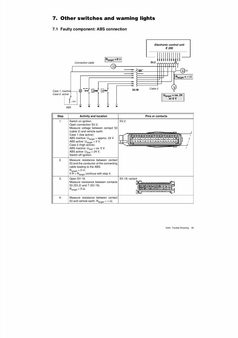
7.1 Faulty component: ABS connection
VP
P
+ 24V
Ω
Ω
Electronic control unit
E 200
Rtarget = ∞ Ω
Rtarget = 0 Ω
Cable 2 Case 1: inactive
Case 2: active
Connection cable
Utarget = ca. 24or 0 V
ABS
Step Activity and location Pins or contacts
1. Switch on ignition.
Open connection SV.2.Measure voltage between contact 53(cable 2) and vehicle earth.Case 1 (low active):ABS inactive: Utarget = approx. 24 VABS active: Utarget = 0 V.Case 2 (high active):ABS inactive: USoll = ca. 0 V.ABS active: USoll = 24 V.Switch off ignition.
SV.2
2. Measure resistance between contact53 and the conductor of the connecting
cable leading to the ABS.Rtarget = 0 Ω.If R = Rtarget continue with step 4.
3. Open SV.19.Measure resistance between contacts53 (SV.2) and 7 (SV.19).Rtarget = 0 Ω.
SV.19; variant
4. Measure resistance between contact53 and vehicle earth. Rtarget = ∞ Ω.
7/22/2019 Voith Diwa.3 Trouble Shooting
http://slidepdf.com/reader/full/voith-diwa3-trouble-shooting 55/70
7. Other switches and warning lights
46 Voith. Trouble Shooting
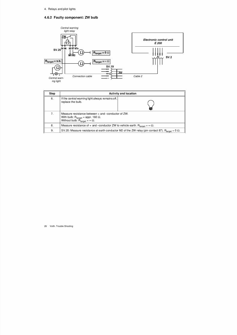
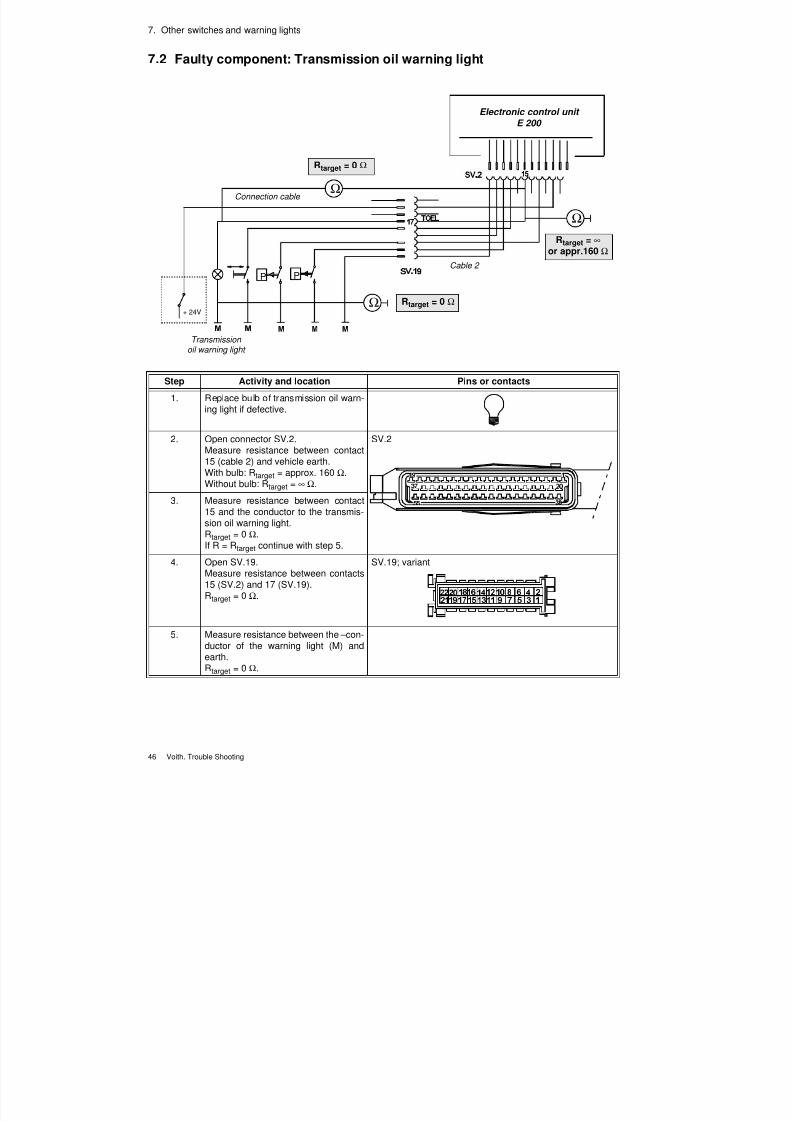
7.2 Faulty component: Transmission oil warning light
+ 24V
Ω
Ω
Ω
P P
Electronic control unit
E 200
Rtarget = ∞ or appr.160 Ω
Rtarget = 0 Ω
Cable 2
Connection cable
Rtarget = 0 Ω
Transmissionoil warning light
Step Activity and location Pins or contacts
1. Replace bulb of transmission oil warn-ing light if defective.
2. Open connector SV.2.Measure resistance between contact15 (cable 2) and vehicle earth.With bulb: Rtarget = approx. 160 Ω.Without bulb: Rtarget = ∞ Ω.
SV.2
3. Measure resistance between contact15 and the conductor to the transmis-sion oil warning light.Rtarget = 0 Ω.If R = Rtarget continue with step 5.
4. Open SV.19.Measure resistance between contacts15 (SV.2) and 17 (SV.19).Rtarget = 0 Ω.
SV.19; variant
5. Measure resistance between the – con-ductor of the warning light (M) andearth.Rtarget = 0 Ω.
7/22/2019 Voith Diwa.3 Trouble Shooting
http://slidepdf.com/reader/full/voith-diwa3-trouble-shooting 56/70
7. Other switches and warning lights
Voith. Trouble Shooting 47
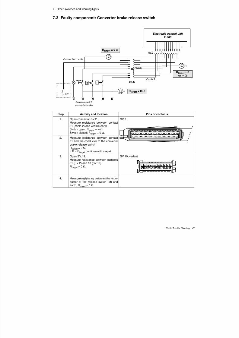
7.3 Faulty component: Converter brake release switch
+ 24V
Ω
Ω
Ω
P P
Electronic control unit
E 200
Rtarget = 0or ∞ Ω
Rtarget = 0 Ω
Cable 2
Connection cable
Rtarget = 0 Ω
Release switch
converter brake
Step Activity and location Pins or contacts
1. Open connector SV.2.Measure resistance between contact
31 (cable 2) and vehicle earth.Switch open: Rtarget = ∞ Ω.Switch closed: Rtarget = 0 Ω.
SV.2
2. Measure resistance between contact31 and the conductor to the converterbrake release switch.Rtarget = 0 Ω.If R = Rtarget continue with step 4.
3. Open SV.19.Measure resistance between contacts31 (SV.2) and 18 (SV.19).
Rtarget = 0 Ω.
SV.19; variant
4. Measure resistance between the – con-ductor of the release switch (M) andearth. Rtarget = 0 Ω.
7/22/2019 Voith Diwa.3 Trouble Shooting
http://slidepdf.com/reader/full/voith-diwa3-trouble-shooting 57/70
7. Other switches and warning lights
48 Voith. Trouble Shooting
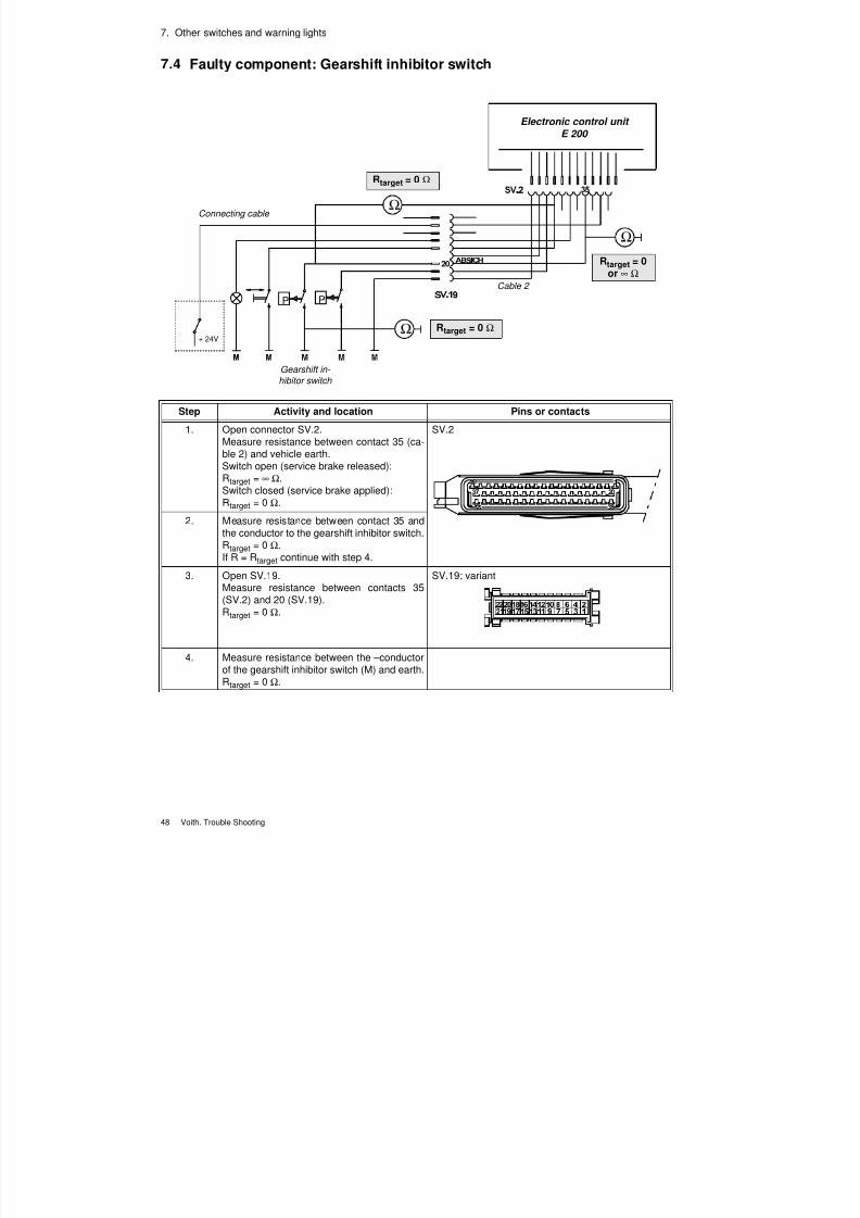
7.4 Faulty component: Gearshift inhibitor switch
+ 24V
Ω
Ω
Ω
P P
Electronic control unit
E 200
Rtarget = 0or ∞ Ω
Rtarget = 0 Ω
Cable 2
Connecting cable
Rtarget = 0 Ω
Gearshift in-
hibitor switch
Step Activity and location Pins or contacts
1. Open connector SV.2.Measure resistance between contact 35 (ca-
ble 2) and vehicle earth.Switch open (service brake released):Rtarget = ∞ Ω.Switch closed (service brake applied):Rtarget = 0 Ω.
SV.2
2. Measure resistance between contact 35 andthe conductor to the gearshift inhibitor switch.Rtarget = 0 Ω.If R = Rtarget continue with step 4.
3. Open SV.19.Measure resistance between contacts 35
(SV.2) and 20 (SV.19).Rtarget = 0 Ω.
SV.19; variant
4. Measure resistance between the – conductorof the gearshift inhibitor switch (M) and earth.Rtarget = 0 Ω.
7/22/2019 Voith Diwa.3 Trouble Shooting
http://slidepdf.com/reader/full/voith-diwa3-trouble-shooting 58/70
7. Other switches and warning lights
Voith. Trouble Shooting 49
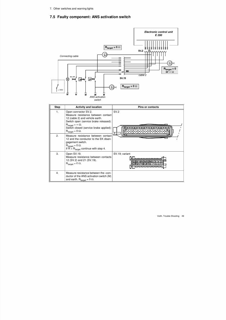
7.5 Faulty component: ANS activation switch
Step Activity and location Pins or contacts
1. Open connector SV.2.Measure resistance between contact
12 (cable 2) and vehicle earth.Switch open (service brake released):Rtarget = ∞ Ω.Switch closed (service brake applied):Rtarget = 0 Ω.
SV.2
2. Measure resistance between contact12 and the conductor to the EK disen-gagement switch.Rtarget = 0 Ω.If R = Rtarget continue with step 4.
3. Open SV.19.
Measure resistance between contacts12 (SV.2) and 21 (SV.19).Rtarget = 0 Ω.
SV.19; variant
4. Measure resistance between the – con-ductor of the ANS activation switch (M)and earth. Rtarget = 0 Ω.
+ 24V
Ω
Ω
Ω
Electronic control unit
E 200
Rtarget = 0or ∞ Ω
Rtarget = 0 Ω
cable 2
Connecting cable
Rtarget = 0 Ω
ANS activation
switch

7/22/2019 Voith Diwa.3 Trouble Shooting
http://slidepdf.com/reader/full/voith-diwa3-trouble-shooting 59/70
7. Other switches and warning lights
50 Voith. Trouble Shooting
7/22/2019 Voith Diwa.3 Trouble Shooting
http://slidepdf.com/reader/full/voith-diwa3-trouble-shooting 60/70
Voith. Trouble Shooting 51
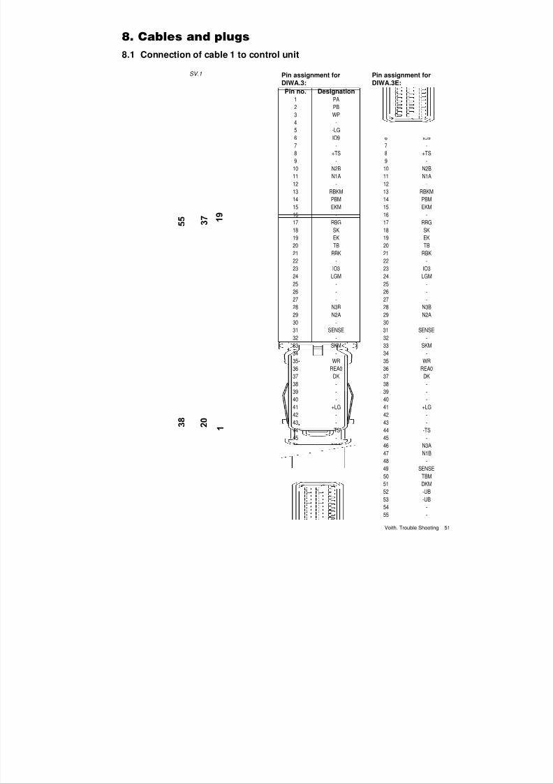
8.1 Connection of cable 1 to control unit
SV.1 Pin assignment forDIWA.3:
Pin assignment forDIWA.3E:
Pin no. Designation Pin no. Designation
1 PA 1 WP
2 PB 2 PB
3 WP 3 -
4 - 4 -
5 -LG 5 -LG
6 IO9 6 IO9
7 - 7 -
8 +TS 8 +TS
9 - 9 -
10 N2B 10 N2B
11 N1A 11 N1A
12 - 12 -
13 RBKM 13 RBKM14 PBM 14 PBM
15 EKM 15 EKM
16 - 16 -
17 RBG 17 RBG
18 SK 18 SK
19 EK 19 EK
20 TB 20 TB
21 RBK 21 RBK
22 - 22 -
23 IO3 23 IO3
24 LGM 24 LGM
25 - 25 -
26 - 26 -27 - 27 -
28 N3B 28 N3B
29 N2A 29 N2A
30 - 30 -
31 SENSE 31 SENSE
32 - 32 -
33 SKM 33 SKM
34 - 34 -
35 WR 35 WR
36 REA0 36 REA0
37 DK 37 DK
38 - 38 -39 - 39 -
40 - 40 -
41 +LG 41 +LG
42 - 42 -
43 - 43 -
44 -TS 44 -TS
45 - 45 -
46 N3A 46 N3A
47 N1B 47 N1B
48 - 48 -
49 SENSE 49 SENSE
50 TBM 50 TBM
51 DKM 51 DKM52 -UB 52 -UB
53 -UB 53 -UB
54 - 54 -
55 - 55 -
7/22/2019 Voith Diwa.3 Trouble Shooting
http://slidepdf.com/reader/full/voith-diwa3-trouble-shooting 61/70
8. Cables and plugs
52 Voith. Trouble Shooting
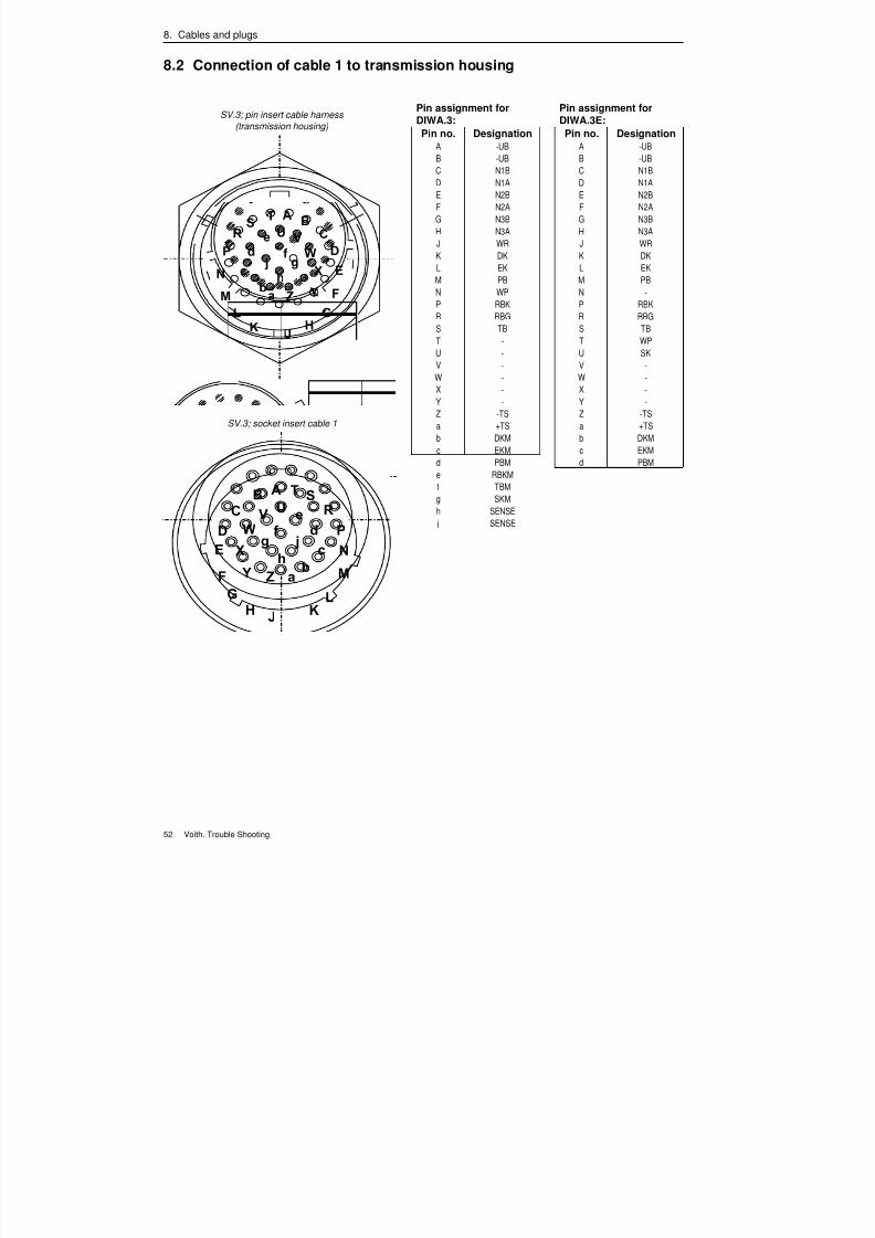
8.2 Connection of cable 1 to transmission housing
SV.3; socket insert cable 1
SV.3; pin insert cable harness
(transmission housing)
Pin assignment forDIWA.3:
Pin assignment forDIWA.3E:
Pin no. Designation Pin no. Designation
A -UB A -UB
B -UB B -UB
C N1B C N1B
D N1A D N1A
E N2B E N2B
F N2A F N2A
G N3B G N3B
H N3A H N3A
J WR J WR
K DK K DK
L EK L EK
M PB M PB
N WP N -
P RBK P RBKR RBG R RBG
S TB S TB
T - T WP
U - U SK
V - V -
W - W -
X - X -
Y - Y -
Z -TS Z -TS
a +TS a +TS
b DKM b DKM
c EKM c EKM
d PBM d PBM
e RBKM e RBKM
f TBM f TBM
g SKM g SKM
h SENSE h SENSE
j SENSE j SENSE
7/22/2019 Voith Diwa.3 Trouble Shooting
http://slidepdf.com/reader/full/voith-diwa3-trouble-shooting 62/70
8. Cables and plugs
Voith. Trouble Shooting 53
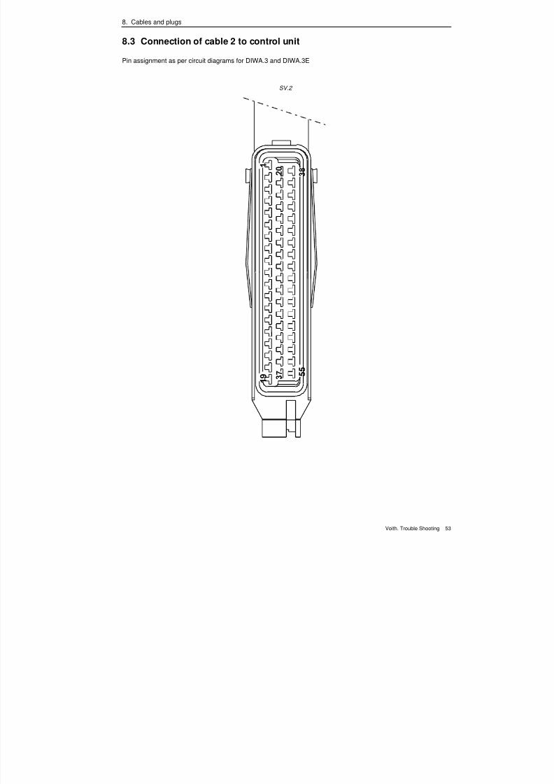
8.3 Connection of cable 2 to control unit
Pin assignment as per circuit diagrams for DIWA.3 and DIWA.3E
SV.2
7/22/2019 Voith Diwa.3 Trouble Shooting
http://slidepdf.com/reader/full/voith-diwa3-trouble-shooting 63/70
8. Cables and plugs
54 Voith. Trouble Shooting
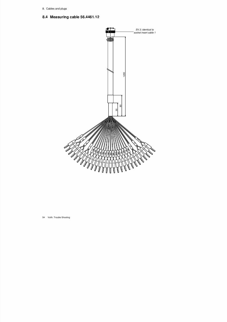
8.4 Measuring cable 56.4461.12
5 0
8 0
1 2 0 0
SV.3; identical to
socket insert cable 1
7/22/2019 Voith Diwa.3 Trouble Shooting
http://slidepdf.com/reader/full/voith-diwa3-trouble-shooting 64/70
8. Cables and plugs
Voith. Trouble Shooting 55
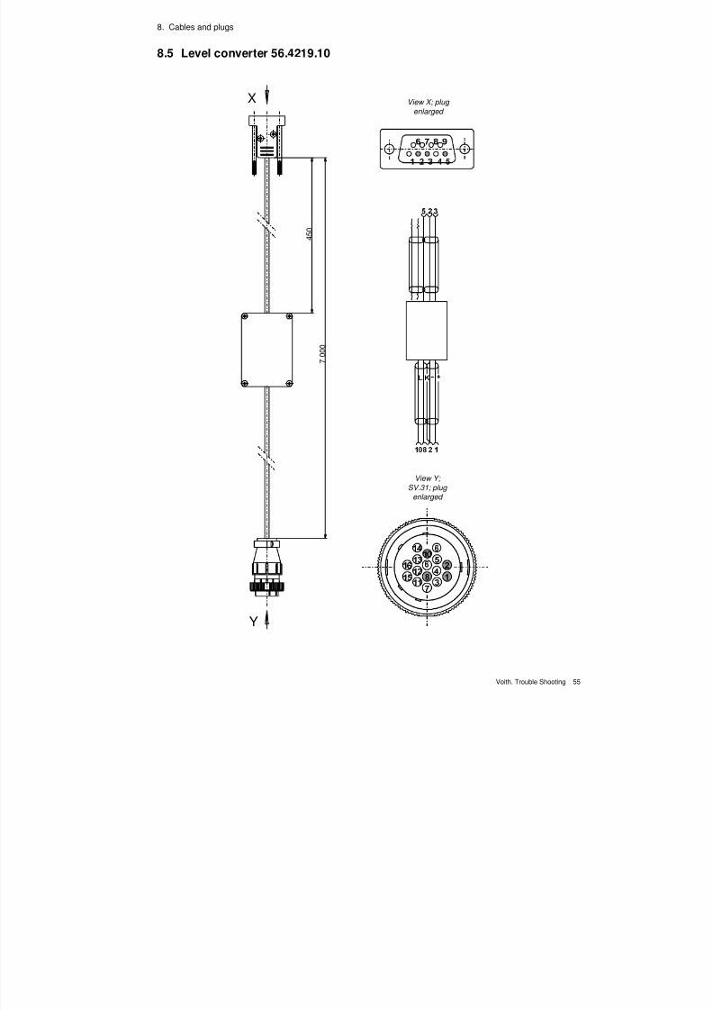
8.5 Level converter 56.4219.10
4 5 0
7
0 0 0
Y
X View X; plug
enlarged
View Y;
SV.31; plug
enlarged

7/22/2019 Voith Diwa.3 Trouble Shooting
http://slidepdf.com/reader/full/voith-diwa3-trouble-shooting 65/70
8. Cables and plugs
56 Voith. Trouble Shooting
7/22/2019 Voith Diwa.3 Trouble Shooting
http://slidepdf.com/reader/full/voith-diwa3-trouble-shooting 66/70
Voith. Trouble Shooting 57
1 Circuit diagram DIWA.3
1 Circuit diagram DIWA.3E

7/22/2019 Voith Diwa.3 Trouble Shooting
http://slidepdf.com/reader/full/voith-diwa3-trouble-shooting 67/70
9. Appendices
58 Voith. Trouble Shooting
7/22/2019 Voith Diwa.3 Trouble Shooting
http://slidepdf.com/reader/full/voith-diwa3-trouble-shooting 68/70
7/22/2019 Voith Diwa.3 Trouble Shooting
http://slidepdf.com/reader/full/voith-diwa3-trouble-shooting 69/70

7/22/2019 Voith Diwa.3 Trouble Shooting
http://slidepdf.com/reader/full/voith-diwa3-trouble-shooting 70/70
Voith Turbo GmbH & Co. KG
Produktgruppe Nutzfahrzeuggetriebe
Alexanderstraße 2
D-89522 Heidenheim
T l h ( )


![Voith DIWA Transmission Type D506[2]](https://img.pdfslide.us/doc/110x75/55cf9806550346d0339515b8/voith-diwa-transmission-type-d5062.jpg)