Embed Size (px)
Citation preview

SIP In DepthVoIP Fundamentals
9
VoIP Call Control & Troubleshooting
SIP dominant intercarrier and carrier-to-customer protocol
Good understanding of its basic operation can help rapidly resolveproblems.
Rationale
10

SIP In Depth
General: Understand SIP Basics
Speci!c:Know what to expect on basic calls
Know basic protocol elements
Read and diagram SIP call "ows
Determine how calls ended
Objectives
11

VoIP Call Control & Troubleshooting
SIP is more like ISDN, whereas MGCP is more like GR.303 or CAS.
Peer-to-Peer Call Control
Used between telephone switches and between users
SIP: Session Initiation Protocol
12

SIP In Depth
Traditional protocols seek to be perfect (ISDN, SS7 ISUP, H.323)t
SIP seeks to be perfectableBasics of SIP generally static
Lots of SIP extensions possible
New features require new extensionsMessage Waiting Indicator
Shared Line Appearance
Add-On Conferencing
Location Conveyance (for 911, pizza orders)
SIP is evolving
13

VoIP Call Control & Troubleshooting
SIP messages come in two forms: requests and responses. A Request must have a Method, such as those listed above.
REGISTER: register with the call server
INVITE: start a call, or change a call
BYE: hang up a call
ACK: acknowledge a completion in an INVITE transaction
PRACK: acknowledge a 1xx response
CANCEL: stop something
SUBSCRIBE: request noti!cations
NOTIFY: notify a subscriber
REFER: Initiate a call transfer
SIP Requests
14

SIP In Depth
#e most common responses are:100 Trying: #e message you sent has been received and will be processed180 Ringing: #e far end is ringing; this causes most SIP phones to create the ringback sound for the caller183 Session Progress: #e call is proceeding; this often means that in-band early-media audio should be cut-through to the calling party200 OK: #e request was completed successfully; for an INVITE, this means the call was answered; for a BYE, it means the call was successfully disconnected. Look in the CSeq header to see the type of request tha30 , or for ext.401 Unauthorized: Typically means you need to authenticate (provide login/password). You should re-sen40un48487 Request Terminated: #at request has been killed, perhaps because you told me to do so with a CANCEL.
#e transaction is complete once a !nal response (200 or greater) is returned. You can only send a !nalresponse if you received a request initially. For example, if you send me an INVITE to setup a call, you cannot terminate the call with a 487 message. You have to terminate the call with a CANCEL or a BYE. Only I can send a response code.
Each request must have a response code100-199: Request in progress (1xx)
200: Request successful
300-399: Redirection
400-499: Client (requester) failure
500-599: Server failure
600-699: “Global” failure
Responses 200-699 are !nal
SIP Responses
15

VoIP Call Control & Troubleshooting
In the following slides, always watch the arrows to see where the message is going. But in regular SIP traces, you need to be sure to get the names or IP addresses of the respective devices to understand who’s saying what to whom, then watch where the packets are going.
A ladder diagram is a convenient way to keep track of where messages are going.
Very common problem: seeing a SIP message and ignoring whosent it
Pay attention to where the request or response is going!
Common troubleshooting mistake
16
SIP In Depth
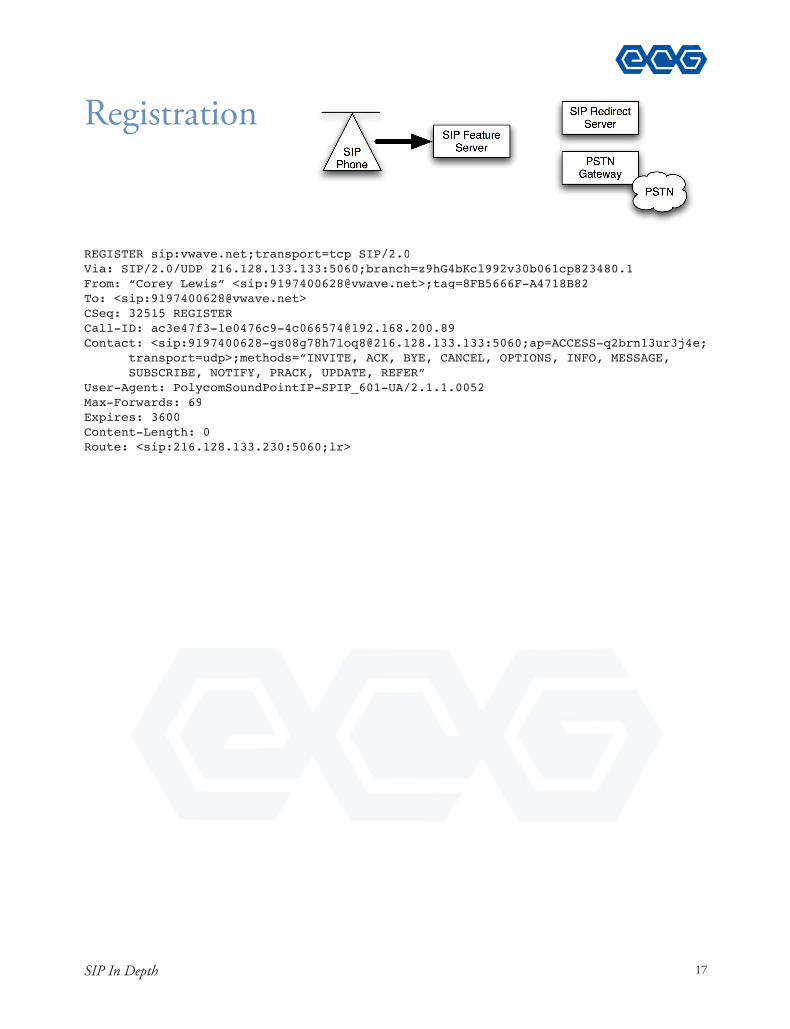
REGISTER sip:vwave.net;transport=tcp SIP/2.0Via: SIP/2.0/UDP 216.128.133.133:5060;branch=z9hG4bKcl992v30b061cp823480.1From: “Corey Lewis” <sip:[email protected]>;tag=8FB5666F-A4718B82To: <sip:[email protected]>CSeq: 32515 REGISTERCall-ID: [email protected]: <sip:[email protected]:5060;ap=ACCESS-q2brn13ur3j4e;
transport=udp>;methods=”INVITE, ACK, BYE, CANCEL, OPTIONS, INFO, MESSAGE,SUBSCRIBE, NOTIFY, PRACK, UPDATE, REFER”
User-Agent: PolycomSoundPointIP-SPIP_601-UA/2.1.1.0052Max-Forwards: 69Expires: 3600Content-Length: 0Route: <sip:216.128.133.230:5060;lr>
Registration
17

VoIP Call Control & Troubleshooting
#e Feature Server refuses the REGISTER because it requires authentication -- a username and password. In SIP, this is done with a WWW-Authenticate header.
#e 401 response is a !nal response to the REGISTER that was sent; that attempt is now dead.
SIP/2.0 401 UnauthorizedVia:SIP/2.0/UDP 216.128.133.133:5060;branch=z9hG4bKcl992v30b061cp823480.1From:”Corey Lewis”<sip:[email protected]>;tag=8FB5666F-A4718B82To:<sip:[email protected]>Call-ID:[email protected]:32515 REGISTERWWW-Authenticate:DIGEST realm=”VoIPFS”,stale=true,qop=”auth”,algorithm=MD5,
nonce=”VoIPFSXf2ezqj3sTxi1756CA”Content-Length:0
Registration
18

SIP In Depth
#e SIP phones doesn’t give up -- it attempts to re-register, this time providing an Authorization header with a user name and encoded password. #e password is encrypted so that it cannot be viewed.
REGISTER sip:vwave.net;transport=tcp SIP/2.0Via: SIP/2.0/UDP 216.128.133.133:5060;branch=z9hG4bKd5gc4800do903ps8a1o0.1From: “Corey Lewis” <sip:[email protected]>;tag=8FB5666F-A4718B82To: <sip:[email protected]>CSeq: 32516 REGISTERCall-ID: [email protected]: <sip:[email protected]:5060;
ap=ACCESS-q2brn13ur3j4e;transport=udp>;methods=”INVITE, ACK, BYE, CANCEL,OPTIONS, INFO, MESSAGE, SUBSCRIBE, NOTIFY, PRACK, UPDATE, REFER”
User-Agent: PolycomSoundPointIP-SPIP_601-UA/2.1.1.0052Authorization: DIGEST username=”Tifton”, realm=”VoIPFS”,
nonce=”VoIPFSXf2ezqj3sTxi1756CA”, qop=auth, cnonce=”wMkyKTKfm4nW3BI”,nc=00000001, uri=”sip:vwave.net;transport=tcp”,
Max-Forwards: 69Expires: 3600Content-Length: 0Route: <sip:216.128.133.230:5060;lr>
Registration
19

VoIP Call Control & Troubleshooting
#at registration attempt is successful; the feature server acknowledges the success with a 200 OK message. Note that the Contact header has an “expires=3599”; that means that the registration is valid for 3,599 seconds -- one second short of a full hour. #is means that the feature server will remember the user’s registration for 3,599 seconds, so it will be able to send calls to the user. #e user is required to re-register before that expiration expires.
#is registration is successful only because the SIP phone has the correct password stored in it.
SIP/2.0 200 OKVia:SIP/2.0/UDP 216.128.133.133:5060;branch=z9hG4bKd5gc4800do903ps8a1o0.1From:”Corey Lewis”<sip:[email protected]>;tag=8FB5666F-A4718B82To:<sip:[email protected]>Call-ID:[email protected]:32516 REGISTERContact:<sip:[email protected]:5060;
ap=ACCESS-q2brn13ur3j4e;transport=udp>;q=0.5;expires=3599Content-Length:0
Registration
20

SIP In Depth
A di$erent user, already registered, sends in a call.$$ #is user, 9197400617, is calling to 9193163111.
#e Call-ID is shown; this is used to correlate with future responses.
#e lower part of the message is the SDP -- Session Description Protocol.
INVITE sip:[email protected];user=phone;transport=tcp SIP/2.0Via: SIP/2.0/UDP 216.128.133.133:5060;branch=z9hG4bKg75q9b1028q0jns2k100.1From: “Lacy Childers” <sip:[email protected]>;tag=BFAA8602-F57F1EF5To: <sip:[email protected];user=phone>CSeq: 1 INVITECall-ID: [email protected]: <sip:[email protected]:5060;transport=udp>Allow: INVITE, ACK, BYE, CANCEL, OPTIONS, INFO, MESSAGE, SUBSCRIBE, NOTIFY, PRACK, UPDATE, REFERUser-Agent: PolycomSoundPointIP-SPIP_601-UA/2.1.0.2708Supported: 100rel,replacesAllow-Events: talk,hold,conferenceMax-Forwards: 69Content-Type: application/sdpContent-Length: 254Route: <sip:[email protected]:5060;user=phone;lr>
v=0o=- 1180665174 1180665174 IN IP4 216.128.159.2s=Polycom IP Phonec=IN IP4 216.128.133.133t=0 0m=audio 21504 RTP/AVP 0 8 18 101a=sendrecva=rtpmap:0 PCMU/8000a=rtpmap:8 PCMA/8000a=rtpmap:18 G729/8000a=rtpmap:101 telephone-event/8000
Calling
21

VoIP Call Control & Troubleshooting
Describes a media path
Sent in an INVITE message to indicate how to send audio TO the calling party
Sent in a 200 OK or other response to show how to send audio TOthe called party
SDP: Session Description Protocol
22

BroadWorks Call Processing
& Troubleshooting
Course Guide

Contents
Course Introduction ........................................................................................ 1
SIP In Depth ................................................................................................... 9
Server Interactions ......................................................................................... 61
Analyzing Logs............................................................................................. 185
Command-Line BroadWorks ....................................................................... 233
Analyzing Packet Captures ........................................................................... 249
TimesTen Database...................................................................................... 259
Most Common Problems for Service Providers ........................................... 271
Terminology Reference ................................................................................ 287
QoS IP Header Packet Marking ................................................................... 290
v

SIP In Depth
#is SDP was present in the INVITE shown earlier. #e key facts:
#e “c=“ (connection) line shows where the RTP audio frames should be sent -- i.e., 216.128.133.133. If this were 0.0.0.0, it means that the call is being placed on hold.
#e “a=“ (attribute) line indicates that the phone expects to send and receive audio. SDP with a=sendonly would put the other end on hold.
#e “m=“ line shows that the RTP should be sent to port 21504. It also shows that the preferred codecs are, in order of preference, 0, 8, 18, and 101. Codec 0 is always G.711u; Codec 8 is G.711a (used in Europe); Codec
Codec“teleph nd DTMF
v=0o=- 1180665174 1180665174 IN IP4 216.128.159.2s=Polycom IP Phonec=IN IP4 216.128.133.133t=0 0m=audio 21504 RTP/AVP 0 8 18 101a=sendrecva=rtpmap:0 PCMU/8000a=rtpmap:8 PCMA/8000a=rtpmap:18 G729/8000a=rtpmap:101 telephone-event/8000
SDP Example
23

BroadWorks Call Processing & Troubleshooting
Now we know:How the AS recognizes an incoming call from a userHow the AS knows where to send the call to reach the called partyHow to determine whether a user is registeredHow AS recognizes a call from the PSTN (i.e., not a local AS user)How the AS informs the NWS of subscriber infoHow AS & NWS sends a call to the PSTNHow to predict where BW will route a call to the PSTN
We don’t know:How the Application Servers communicate with each other for failover protectionHow voicemails are stored or retrievedHow the AS & NWS play audio to users, and record audio from users
Status
104

Server Interactions
Normally, all call processing occurs on AS1. Alice and Bob, SIP access devices, communicate only with AS1. #e PSTN gateway communicates only with AS1. And AS1 sends noti!cations to the other servers to let them know which users are active on AS1.
Application Server Fault Tolerance: All Servers OK
Alice
AS1
PSTNGateway
D21e
Bob
NWS1 NWS2
AS2
SIP
SIPSIPSIP
TimesTen
Database
ASR"Bob is on AS1", "Alice is on AS1"
ASR"Bob is on AS1""Alice is on AS1"
I I I I
105

BroadWorks Call Processing & Troubleshooting
When the Access devices and Network devices start sending tra%c to AS2, the users are considered “migrated”. AS2 then sends updates to AS1 and to the Network Servers to inform them that the users are reachable through AS2.
Endpoints decide when to use AS2
Alice
AS1
PSTNGateway
D22e
Bob
NWS1 NWS2
AS2
SIPSIPSIP
TimesTen Database
ASR"Bob is on AS2""Alice is on AS2"
ASR
"Bob is on AS2", "Alice is on AS2"
ASR"Bob is migrated", "Alice is migrated"
x x I I
106

Server Interactions
SIP Access devices, Network Gateways, proxies (like SBCs) mustdecide when to communicate to AS2
Each SIP device decides independently
How do they decide? Timeout. #ey fail to receive a response fast enough from AS1
You can list the migrated users in the AS bwcli
AS_CLI/System/Redundancy/MigratedUsers> get User Id=======================
[email protected] [email protected] [email protected]
What triggers failover?
107

BroadWorks Call Processing & Troubleshooting
Yikes! Failover is on a per user basis?
BroadWorks’ !ne-grained per-user failover is very complex
Many other VoIP products do a whole system-wide failover
Upside: Allows both AS1 and AS2 to be loosely coupled; they can beon di$erent continents$$
Downside: When a user is migrated to AS2, AS2 doesn’t know about standing calls for AS1
108

Server Interactions
When activity for a user appears on AS2, AS2 takes responsibility for that user
AS2 then sends messages to AS1 to notify AS1 that users have been migrated to AS2
When AS1 recovers, it immediately tries to migrate users back to AS1
AS1 must successfully complete SIP or MGCP signaling to the userbefore the user is considered migrated back to AS1
AS2’s job, AS1’s recovery
109

BroadWorks Call Processing & Troubleshooting
SIP from AS1 to recovering user
Alice
AS1
PSTNGateway
D23e
Bob
NWS1 NWS2
AS2
SIP
ASR"Alice is on AS1"
#3
#1 #2
200
OPTIONS
ASR ASR
110

Acme Packet® Boot Camp
SIP Trunks & Registration
Course Guide

Contents
Preface ........................................................................................................... vii
Course Introduction .......................................................................................... 1
Session Border Controllers ................................................................................ 7
How SBCs Fit ................................................................................................ 10
Classic Model ................................................................................................. 24
SIP & NAT Review ....................................................................................... 27
SBCs and NAT Traversal ................................................................................ 34
SIP Peering .................................................................................................... 55
IP Addressing Design Options ....................................................................... 58
Designing Con!gurations ............................................................................... 63
Realm ............................................................................................................ 64
Command Line Interface ............................................................................... 69
Local Policy .................................................................................................... 74
SIP Interface .................................................................................................. 77
Session Agent ................................................................................................. 80
Steering Pool .................................................................................................. 85
Session Agent Group ...................................................................................... 89
Denial of Service Protection ........................................................................... 97
Access Control for Untrusted Devices .......................................................... 104
Media Manager ............................................................................................ 106
Access Control for Trusted Devices .............................................................. 107
Network Interface ........................................................................................ 110
Phy Interface ................................................................................................ 115
Media Policy ................................................................................................ 117
v

Acme Packet® Boot Camp
Header Manipulation Rules ......................................................................... 121
Session Agents Shared Across Realms ........................................................... 132
SIP Registration ........................................................................................... 136
SIP Feature .................................................................................................. 145
Operational Troubleshooting ........................................................................ 153
Viewing Logs on SD .................................................................................... 154
show support-info ........................................................................................ 160
Realm Statistics ............................................................................................ 161
Interpreting SIP Statistics ............................................................................. 163
SD Generating Errors .................................................................................. 166
Device Losing Registration ........................................................................... 167
SIP Retransmissions ..................................................................................... 168
Dynamic and Static ACLs ............................................................................ 169
SD CPU Limits ........................................................................................... 172
Con!guration Change History..................................................................... 173
Appendix ....................................................................................................... 179
Terminology Reference ................................................................................ 179
QoS IP Header Packet Marking ................................................................... 182
Subnet Mask Cheat Sheet ............................................................................ 183
vi

Acme Packet® Boot Camp
For example: An INVITE SIP message arrives at the SBC setting up a call; the SIP says to send SIP responses to 192.168.0.15 port 5060, and to send the audio to 192.168.0.15 port 49152. But the SBC sees that IP packet came from the device 216.128.129.5 port 3262. !ere’s a di"erence, so the SBC knows that NAT has occurred. If the SBC sent a packet to 192.168.0.15, the response would never reach the SIP phone, because 192.168.0.15 (a) cannot route across the Internet, and (b) is behind a #rewall.
Instead of following the rules of SIP, the SBC sends the SIP response to 216.128.129.5 port 3262 -- back to the pinhole. !e #rewall receives this, NATs the IP/UDP headers, and sends the packet back to the phone at the same port from which the phone sent its SIP. I.e., if the SIP phone sent its UDP from port 5062, then the response will go back to port 5062. If the SIP phone allows symmetric signaling, then the signaling will work. For example, the Cisco SIP phones have an option, “nat_enable”, that controls symmetric signaling support.
After the remote side answers the call, audio needs to start $owing. It’s not clear yet where the RTP should be sent, because the SBC’s only information is to send it to a NAT’d IP. But once the NAT’d SIP phone starts sending audio, a new pinhole is created. Suppose it sends its RTP to the SBC, and it arrives at the SBC as coming from 216.128.129.5 port 3263/UDP. !e SBC then has a pinhole to send the RTP back through; it will send its RTP to that same IP and port. !e #rewall will allow the RTP packets back through to the SIP phone. If the phone allows symmetric media, then the audio will work.
SIP/SDP embed IPs and ports that are not properly NAT’d
SBC ignores those embedded IPs and ports
SBC sends response to the pinhole
Requires symmetric signaling and media ports
SBCs and NAT Traversal
34

Session Border Controllers
!is shows an example call placed by a NAT’d endpoint device to a VoIP carrier using an SBC. !e SIP endpoint has the IP address 192.168.0.2.
First, the INVITE is sent by the endpoint, using its own addresses in the IP, UDP, SIP, and SDP. !e endpoint doesn’t do anything di"erent because of the presence of the SBC. It is con#gured with the outbound proxy 216.128.133.133.
Internet router
Internet192.168.0.0/24
NAT DeviceCustomer 2 216.128.130.36/30
Network Printer Windows Server
.7 .8
.1
.38 .37
SBC
PayloadLayer 5
IP HeaderLayer 3
UDP HeaderLayer 4
Source Port:5060Dest Port:5060
Source IP:192.168.0.2Dest IP:216.128.133.133
192.168.0.2 23214 216.128.156.30 801912
Inside IPInside Port
Remote IPRem.Port
Ext.Port
216.128.130.38
External IP
INVITE sip:bob@fooVia: 192.168.0.2:5060
c=IN IP4 192.168.0.2m=audio 5000 RTP/AVP 0 18
216.128.133.133
216.128.134.10
VoIP ServerCall Agent
216.128.134.11
VoIP Server Media Gateway216.128.134.12
SIPPhone�
.2
NAT-VoIP SBC 01 (24 of 38)
Inside IP Inside Port Remote IP Rem.
PortExt.PortExternal IP
35

Acme Packet® Boot Camp
!e NAT router creates a translation for this UDP "ow.
!e SIP phone sent its packet from 192.168.0.2 port UDP/5060. So this is stored as the Inside IP and Inside Port.
!e SIP phone was sending its packet to 216.128.133.133 port UDP/5060. So this is stored as the Remote IP and Remote port.
!e NAT device allocates a new port number and a public IP address. It only has one public IP to use: 216.128.130.38. And the external port number it uses for this “pinhole” is UDP/21543.
Internet router
Internet192.168.0.0/24
NAT DeviceCustomer 2 216.128.130.36/30
Network Printer Windows Server
.7 .8
.1
.38 .37
PayloadLayer 5
IP HeaderLayer 3
UDP HeaderLayer 4
Source Port:5060Dest Port:5060
Source IP:192.168.0.2Dest IP:216.128.133.133
192.168.0.2 23214 216.128.156.30 801912
Inside IPInside Port
Remote IPRem.Port
Ext.Port
216.128.130.38
External IP
INVITE sip:bob@fooVia: 192.168.0.2:5060
c=IN IP4 192.168.0.2m=audio 5000 RTP/AVP 0 18
SBC
216.128.133.133
216.128.134.10
VoIP ServerCall Agent
216.128.134.11
VoIP Server Media Gateway216.128.134.12
SIPPhone�
.2
NAT-VoIP SBC 02 (25 of 38)
192.168.0.2 5060 216.128.133.133 506021543
Inside IP Inside Port Remote IP Rem.
PortExt.Port
216.128.130.38
External IP
36

Session Border Controllers
!e NATd packet is sent through the Internet to the SBC.
!e IP header has legal, routable Internet IP addresses in them, but the SIP payload still has the private IP and port numbers.
Internet routerNAT DeviceCustomer 2
Network Printer Windows Server
PayloadLayer 5
IP HeaderLayer 3
UDP HeaderLayer 4
Source Port:21543Dest Port:5060
Source IP:216.128.130.38Dest IP:216.128.133.133
192.168.0.2 23214 216.128.156.30 801912
Inside IPInside Port
Remote IPRem.Port
Ext.Port
216.128.130.38
External IP
192.168.0.0/24
216.128.130.36/30
.7 .8
.1
.38.37
INVITE sip:bob@fooVia: 192.168.0.2:5060
c=IN IP4 192.168.0.2m=audio 5000 RTP/AVP 0 18
Internet
SBC
216.128.133.133
216.128.134.10
VoIP ServerCall Agent
216.128.134.11
VoIP Server Media Gateway216.128.134.12
SIPPhone�
.2
NAT-VoIP SBC 03 (26 of 38)
192.168.0.2 5060 216.128.133.133 506021543
Inside IP Inside Port Remote IP Rem.
PortExt.Port
216.128.130.38
External IP
37

Acme Packet® Boot Camp
!e NAT’d packet arrives at the SBC.
At this point the SBC can detect that there’s a NAT traversal process required. It can detect that because the VIA header does not match the source IP address. In particular the VIA header matches 192.168.0.2, but the source IP for this packet is 216.128.130.38. Because of this, the SBC knows that a special process is required. It’s going to have to work around this SIP problem in a very speci"c way.
Notice also that the SBC does not know at this point how to send audio back to the device. !e SDP portion says to send audio to 192.168.0.2 port 5000, and it also speci"es the preferred codex. However, the SBC is smart enough to know that in a NAT situation, it’s not going to know how to send tra#c to 192.168.0.2 port 5000. It knows that this is an IP address that’s behind a NAT device, and so as of now, the SBC has no ability to send audio RTP to the calling device.
Internet routerNAT DeviceCustomer 2
Network Printer Windows Server
PayloadLayer 5
IP HeaderLayer 3
UDP HeaderLayer 4
Source Port:21543Dest Port:5060
Source IP:216.128.130.38Dest IP:216.128.133.133
192.168.0.2 23214 216.128.156.30 801912
Inside IPInside Port
Remote IPRem.Port
Ext.Port
216.128.130.38
External IP
192.168.0.0/24
.7 .8
.1
216.128.130.36/30.38 .37
INVITE sip:bob@fooVia: 192.168.0.2:5060
c=IN IP4 192.168.0.2m=audio 5000 RTP/AVP 0 18
Internet
SBC216.128.133.133
216.128.134.10
VoIP ServerCall Agent
216.128.134.11
VoIP Server Media Gateway216.128.134.12
SIPPhone�
.2
NAT-VoIP SBC 04 (27 of 38)
192.168.0.2 5060 216.128.133.133 506021543
Inside IP Inside Port Remote IP Rem.
PortExt.Port
216.128.130.38
External IP
38
Session Border Controllers
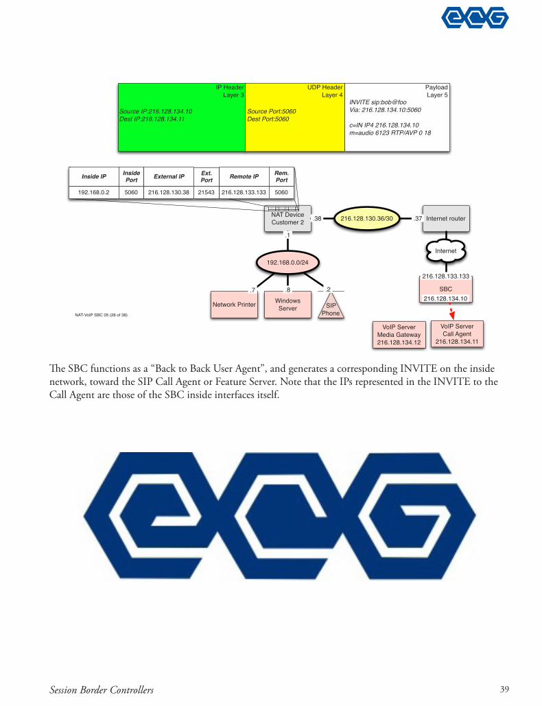
!e SBC functions as a “Back to Back User Agent”, and generates a corresponding INVITE on the inside network, toward the SIP Call Agent or Feature Server. Note that the IPs represented in the INVITE to the Call Agent are those of the SBC inside interfaces itself.
Internet routerNAT DeviceCustomer 2
Network Printer Windows Server
PayloadLayer 5
IP HeaderLayer 3
UDP HeaderLayer 4
Source Port:5060Dest Port:5060
Source IP:216.128.134.10Dest IP:216.128.134.11
192.168.0.2 23214 216.128.156.30 801912
Inside IPInside Port
Remote IPRem.Port
Ext.Port
216.128.130.38
External IP
192.168.0.0/24
.7 .8
.1
216.128.130.36/30.38 .37
INVITE sip:bob@fooVia: 216.128.134.10:5060
c=IN IP4 216.128.134.10m=audio 6123 RTP/AVP 0 18
Internet
SBC
216.128.133.133
216.128.134.10
VoIP ServerCall Agent
216.128.134.11
VoIP Server Media Gateway216.128.134.12
192.168.0.2 5060 216.128.133.133 506021543
Inside IP Inside Port Remote IP Rem.
PortExt.Port
216.128.130.38
External IP
SIPPhone�
.2
NAT-VoIP SBC 05 (28 of 38)
39
Acme Packet® Boot Camp
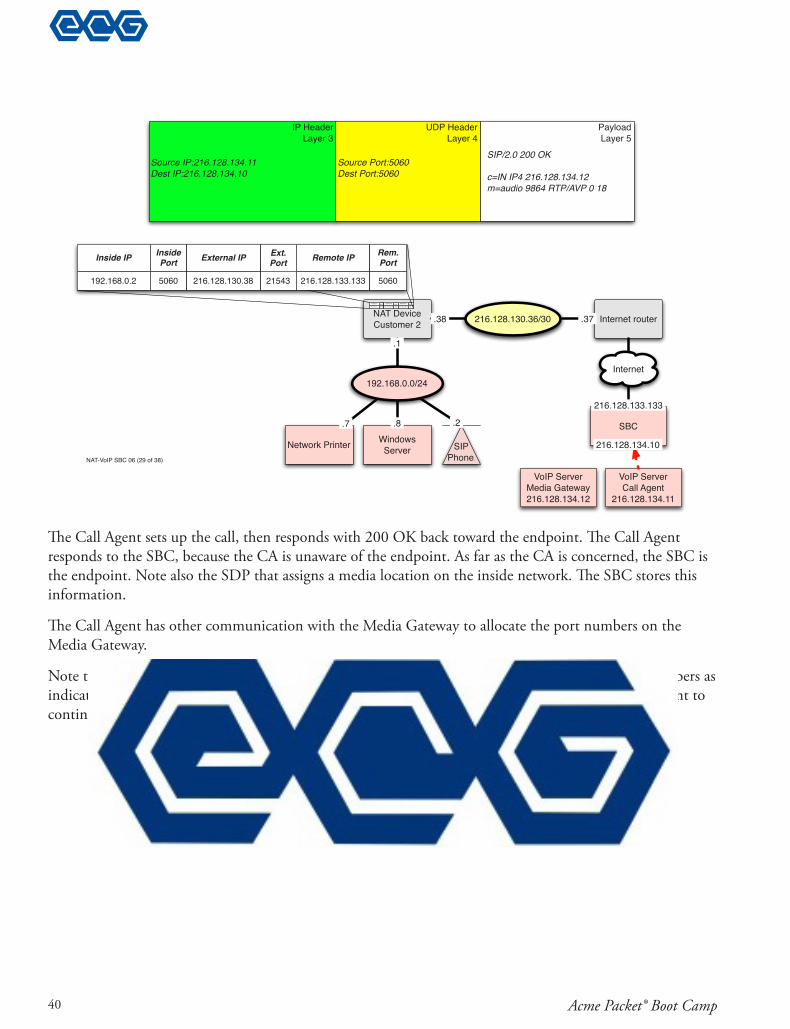
!e Call Agent sets up the call, then responds with 200 OK back toward the endpoint. !e Call Agent responds to the SBC, because the CA is unaware of the endpoint. As far as the CA is concerned, the SBC is the endpoint. Note also the SDP that assigns a media location on the inside network. !e SBC stores this information.
!e Call Agent has other communication with the Media Gateway to allocate the port numbers on the Media Gateway.
Note that the Call Agent is able to follow the SIP standards, and reply to the IP address and port numbers as indicated in the SIP message that it received (from the SBC). In this way, the SBC allows the Call Agent to continue to enforce the Internet standards.
Internet routerNAT DeviceCustomer 2
Network Printer Windows Server
PayloadLayer 5
IP HeaderLayer 3
UDP HeaderLayer 4
Source Port:5060Dest Port:5060
Source IP:216.128.134.11Dest IP:216.128.134.10
192.168.0.2 23214 216.128.156.30 801912
Inside IPInside Port
Remote IPRem.Port
Ext.Port
216.128.130.38
External IP
192.168.0.0/24
.7 .8
.1
216.128.130.36/30.38 .37
Internet
SBC
VoIP ServerCall Agent
216.128.134.11
216.128.133.133
216.128.134.10
SIP/2.0 200 OK
c=IN IP4 216.128.134.12 m=audio 9864 RTP/AVP 0 18
VoIP Server Media Gateway216.128.134.12
SIPPhone�
.2
NAT-VoIP SBC 06 (29 of 38)
192.168.0.2 5060 216.128.133.133 506021543
Inside IP Inside Port Remote IP Rem.
PortExt.Port
216.128.130.38
External IP
40

Session Border Controllers
!e SBC generates a corresponding 200 OK and sends it back toward the endpoint. However, it doesn’t honor the original SIP INVITE Via header -- instead, it responds to the IP and UDP from which the INVITE came. !is ensures that the response goes back to the outside of the NAT device, and reaches the pinhole created for this UDP "ow.
Note also that the SDP contains IPs and ports of the outside of the SBC itself. !is SBC will relay all RTP through itself between the two endpoints.
Internet routerNAT DeviceCustomer 2
Network Printer Windows Server
PayloadLayer 5
IP HeaderLayer 3
UDP HeaderLayer 4
Source Port:5060Dest Port:21543
Source IP:216.128.133.133Dest IP:216.128.130.38
192.168.0.2 23214 216.128.156.30 801912
Inside IPInside Port
Remote IPRem.Port
Ext.Port
216.128.130.38
External IP
SIP/2.0 200 OK
c=IN IP4 216.128.133.133 m=audio 2134 RTP/AVP 0 18
192.168.0.0/24
.7 .8
.1
Internet
216.128.130.36/30.38 .37
SBC
216.128.133.133
216.128.134.10
VoIP ServerCall Agent
216.128.134.11
VoIP Server Media Gateway216.128.134.12
SIPPhone�
.2
NAT-VoIP SBC 07 (30 of 38)
192.168.0.2 5060 216.128.133.133 506021543
Inside IP Inside Port Remote IP Rem.
PortExt.Port
216.128.130.38
External IP
41

Acme Packet® Boot Camp
!e NAT router NATs the 200 OK IP and UDP headers, and forwards the packet back to the calling endpoint.
!e NAT router allows the response packet to be sent back through because it found a match: the packet came from the Remote IP and Remote Port, and it was sent to the External IP and External Port.
Internet router
Internet192.168.0.0/24
NAT DeviceCustomer 2 216.128.130.36/30
Network Printer Windows Server
.2.7 .8
.1
.38 .37
PayloadLayer 5
IP HeaderLayer 3
UDP HeaderLayer 4
Source Port:5060Dest Port:5060
Source IP:216.128.133.133Dest IP:192.168.0.2
192.168.0.2 23214 216.128.156.30 801912
Inside IPInside Port
Remote IPRem.Port
Ext.Port
216.128.130.38
External IP
SBC
216.128.133.133
216.128.134.10
VoIP ServerCall Agent
216.128.134.11
VoIP Server Media Gateway216.128.134.12
SIP/2.0 200 OK
c=IN IP4 216.128.133.133 m=audio 2134 RTP/AVP 0 18
192.168.0.2 5060 216.128.133.133 506021543
Inside IP Inside Port Remote IP Rem.
PortExt.Port
216.128.130.38
External IP
SIPPhone�NAT-VoIP SBC 08 (31 of 38)
42

Session Border Controllers
Silence Supression, also known as Voice Activity Detection, or VAD, creates a special problem for NAT’d environments. When VAD is enabled on a SIP phone, the SIP phone does not send audio RTP unless the user is talking. In the common telephone call, the called party answers and speaks, but the calling party does not speak.
!ink about how this a"ects the NAT RTP pinhole creation. If the calling party has to speak before the SIP phone transmits an RTP frame, then the pinhole won’t be created until the calling party speaks! !is creates a situation where the calling party cannot hear certain forms of ringback (i.e., the type streamed back via RTP usually after a SIP 183 with SDP). !e calling party may also not even hear the called party answer.
Another problem with VAD is the implementations: they’re usually not clever enough to send all of the audio. !ey typically wait until the talker loudness is great enough to cross a threshold, and then the system starts transmitting RTP. But by the time the threshold has been crossed, some useful audio has been left out. So the listener might lose a syllable, or even a whole word.
So we recommend disabling VAD for VoIP endpoints, unless it: (a) transmits at least one RTP frame each time the SDP parameters arrive; (b) transmits all the useful audio, even if it occurred before the speech-energy threshold was crossed.
AKA Voice Activity Detection (VAD)
Causes endpoint to not send RTP in silence
We need RTP from NAT’d endpoint to create pinhole
Recommendation: Turn o" VAD for VoIP endpoints (unless it’s the smarter variety)
Silence Suppression
53

Acme Packet® Boot Camp
Early Media is audio that !ows before the call is actually connected. "e common case is for audio to !ow from the called party back toward the calling party, and this would be a recording such as “Your call cannot be completed as dialed” or “Please enjoy the music while your party is being located”, or it could just be an ordinary ringing sound. When you make a call, for example, to an international location, you hear the ringback that comes from that international location. A ringback from Italy sounds di#erent then a ringback coming from England, sounds di#erent then a ringback coming from Japan. And so in each case you want to hear the actual ringback coming from the called location to indicate that the call has been switched all the way through to the destination.
Additionally, the destination may have information such as the announcement “"is call cannot be completed as dialed,” or “All circuits are busy,” anything like that needs to come back as early media. However, as we discussed earlier in our depiction of the SBC process with RTP, the SBC cannot send media back towards the calling device until the calling device has actually transmitted some RTP. When the calling device transmits RTP, that creates the pinhole in the translation table of the NAT device, and creates the NAT’d packet which is transmitted from the NAT device to the SBC. When the SBC receives that packet, it knows, therefore, how to send RTP back to the calling device. Until that happens, the SBC has no way of sending RTP towards the calling device. However, in the SIP standards, there is actually no requirement for the calling device to send RTP until it actually has something to say.
But for these practical purposes, carrier compatible VoIP devices will transmit RTP towards the called device. "ey know when to do this when they receive a 183 or a 180 SIP response, either of which contains SDP. "e SDP provides the RTP destination information to the calling device, so that the calling device will know how and where to send its RTP to the called device. When the SIP phone that’s making the call starts transmitting RTP toward the called device, this will create a translation in the NAT pinhole so that the SBC will know how to send RTP back toward the calling device.
In SIP Phone to PSTN Call, PSTN sends ringback as RTP stream to SIP Phone
SIP phone must open pinhole to receive that early media RTP
Called Call Server hints at early media by sending 183 to calling phone
Early Media & PSTN Ringback
54
Session Border Controllers
As an example of static IP-address-based peering, consider a Call Server (such as a feature server) inside the protected VoIP network having the IP address 216.128.129.5. It needs to send SIP and media to the device at IP 4.0.5.2, but this Call Server shouldn’t receive SIP and RTP from elsewhere on the Internet. !e SBC between the Call Server and the Internet can enable this.
A typical approach would be to assign an IP to the SBC on the inside network; e.g., 216.128.129.15; there’s a corresponding IP on the external/public network; this might be 216.128.128.135.
To send a call to the peer, the Call Server would send a SIP INVITE to 216.128.129.15. !e SBC would relay this through so that a SIP INVITE goes from 216.128.128.135 to 4.0.5.2. !e Call Server isn’t actually even aware of the IP address 4.0.5.2; all it sees is 216.128.129.15. Likewise, the peer at 4.0.5.2 cannot see the internal infrastructure at 216.128.129.5; all it sees is 216.128.128.135. (!is is sometimes called a feature, “infrastructure hiding”.)
When SIP arrives from 4.0.5.2 to 216.128.128.135, the SBC can relay it through to the Call Server. !e Call Server would see a call arriving from 216.128.129.15.
When RTP packets arrive at the SBC from the Internet, the SBC can determine whether they are an authorized part of a call. If they are, then it can relay them through to the internal devices. Likewise, if SIP arrives at the SBC from the Internet, it can determine whether they should be allowed through. A common policy would be to block all SIP except that associated with established peerings, or with registered/registering devices. !is helps prevent SIP/RTP attacks.
Not all devices register
Peering with outside PSTN carriers common
Typical SBC Solution: Static IP-address-based mapping
SIP Peering
55

Acme Packet® Boot Camp
Some SIP devices cannot send REGISTER messages; often, these are PRI/PBX gateways and IADs.
If these devices can be trusted as part of the VoIP core network, then they can be put “inside the trust boundary” -- i.e., so they have free access to all of the internal equipment. You may be able to avoid NAT’ing between the VoIP Core equipment and those CPE.
But what if customers’ PCs can access the VoIP core network, too? !is might be the case with an IAD doing SIP and functioning as a router. Customers behind that IAD could access the VoIP core network. !is means there is limited "rewall protection between the VoIP core network and Customers computers. Even the best customers are susceptible to Internet worms; when the "rst SIP or RTP worms start spreading, you’ll want to have an SBC and "rewall between those customers and your VoIP Core.
When you have to put a gateway on the outside of your trust boundary, then a static mapping through an SBC can enable the device to work. But this now means that provisioning in the SBC has to be done to enable every such device. Normally, no provisioning in the SBC is required for registering SIP devices. For this reason alone, some service providers refuse to support non-registering SIP devices.
Some SIP devices can’t REGISTER
Trustworthy devices? Inside trust boundary
Everybody else? Static SBC mappings (SIP peering)
Non-Registering VoIP Devices
56

Session Border Controllers
!is depicts a typical IP-address-based SIP peering.
At the top we have typical registering SIP and MGCP endpoint devices. !ey REGISTER or, in the case of MGCP, send in RSIP messages to announce their presence. !e SBC can perform NAT Traversal to allow these devices to be on NAT’d networks.
63.113.52.5 is a remote VoIP peer; for example, it could represent Verizon’s SIP signaling gateway. It will not send in a REGISTER. So you can de"ne a new IP address on the SBC, then you’d tell Verizon to send SIP to 216.128.128.16. You also de"ne a new Ip address on the inside of the SBC, 216.128.129.6. !en you de"ne a SIP trunk in your VoIP Call Server for 216.128.129.6. When the Call Server wants to send a call to Verizon, it sends the INVITE to 216.128.129.6; the SBC proxies this through and sends an INVITE from 216.128.128.16 to 63.113.52.5. In this way, communication through an SBC with a non-registering device is supported.
SIP Peering using an SBC
57

Acme Packet® Boot Camp
Activities1. Describe a “realm” in your own words.
2. What is given as the primary job of the SD? Do you see any limitations or problems with this de!nition, based on your experience, or what you’ve been told or read?
3. Is a pre-de!ned rule used to have tra"c pass between a call server and non-registering devices?
4. Is a pre-de!ned rule used to have tra"c pass between a call server and registering devices?
5. What are the four IP addresses involved in a SIP peering? (I.e., what do each of them represent?) What are the upsides to de!ning these four IP addresses on a SIP peering? What are the downsides?
6. Every time you show the running con!guration on the SD (with “show running”), you see all the values in use. On many devices, like Cisco routers, you normally just see the values you have modi!ed. Do you like the way the SD shows all of the values in use on a con!guration?
7. What values are normally used in the con!guration to represent a setting that is disabled?
8. Acme Packet recommends naming the realms “peer-TAG” (where “TAG” is some name, like a customer ID) and “core-TAG”. Is this a good naming convention? Can you suggest other ideas that might work better?
9. What are the minimum values that MUST be de!ned for a realm?
10. Which setting in a realm is involved with Quality of Service and Prioritization in routers?
11. Which setting in the realm can change the contents of the headers based on arbitrary rewrite rules?
12. In the recommended con!guration, what happens if the peer device sends this SIP packet to the SD?
,19,7(�VLS�IRR#EDU�6,3����
9LD��6,3�����8'3�7KLV�6,3�ZRQ±W�SDUVH�ULJKW�EUDQFK ]�DEFGHIJK
)URP���VLS�ED]#EDP!�WDJ DEFGHI
7R���VLS�IRR#EDU!
&RQWHQW�/HQJWK���
13. After logging in to the SD with ssh or telnet, what do you have to type to access the con!guration mode? (Show the steps in your answer.)
72

Designing Con!gurations
14. Once in con!guration mode, !nd your way to each of these con!guration elements, then create one of each of these. Save your objects with your own name; e.g., name each object “frank-1” if your name is Frank.
sip-interface
ntp-sync
realm-con!g
media-policy
sip-nat
local-policy
15. Explain the di"erence between the atomic-commit model of the SD and the alternative (where commands are activated immediately on pressing “enter” or changing a #ag.)
16. What are the three distinct complete con!gurations stored on the SD? How does the “save-con!g” command change things?
17. When you are actively editing an object before you save it on the con!guration mode, is that object stored in one of the three con!gurations mentioned above, or is it stored somewhere else?
18. What are the di"erences between the core-caribenet and peer-caribenet realms? Explain each di"erence.
73

Acme Packet® Boot Camp
!e original way to send tra"c between realms was with sip-nats and sip-nat bridges.
sip-nat is considered arcane and heavyweight, because the sip-nat does search-and-replace replacements of IPs and domain names; very CPU intensive.
sip-nat also organized around a simplistic network design model.
Acme Packet has mostly abandoned the sip-nat.
!e newer method is called Policy-Based Realm Bridging. You use an object called “local-policy” to connect tra"c between realms.
!e local-policy simply sends tra"c between realms, and does not (by default) do all of the SIP header rewriting that you would want.
SD’s job is to connect SIP calls between realms.
Old way: sip-nat
Newer way: local-policy
How Do You Cross Between Realms?
���
����
������ �
����
������������� ������������
�����
74

Designing Con!gurations
!e Local Policy routes tra"c that is received on a speci#c realm outbound to another realm, and to a speci#c destination. It has a number of options, but this is the most common use.
Local Policy
�������������������������������
���������������������������
"�#�#�$"�"� �#
%��#�� �#!
���������������������������
"�#�#�%
!�#���
"�"�����
���������
�� ����
"�"�����
75

Acme Packet® Boot Camp
!is summarized view shows the basic routing from the peer-caribenet realm to the core-caribenet route. !e SIP message will be transmitted at Layer-3 to “caribenet-dedicated-cs.voipco.net”, which has the IP address 4.4.2.5. (See the session-agent to see where this IP is de"ned. DNS can be used here, but we don’t recommend it.)
local-policy:source-realm identi"es the input side of the local policy. !is local-policy will only match tra#c that is coming FROM that speci"ed realm.
local-policy:policy-attribute:next-hop speci"es the IP address of the SIP UA (server, in this case) to which matching tra#c should be sent.
local-policy:policy-attribute:realm speci"es the realm out of which the tra#c should be sent to the SIP UAS.
Note that by creating this local policy from peer-caribenet to core-caribenet, we will enable responses to the SIP requests to be routed back to the UA client (i.e., calling party).
ORFDO�SROLF\� IURP�DGGUHVV�������������������� ������������������������������� � WR�DGGUHVV���������������������� ������������������������������� � VRXUFH�UHDOP�������������������� �������������������������������peer-caribenet� GHVFULSWLRQ��������������������5RXWH�IURP�&DULEH1HW�WR�&DOO�6HUYHU� SROLF\�DWWULEXWH� � QH[W�KRS��������������������caribenet-dedicated-cs.voipco.net� � UHDOP�����������������������core-caribenet
Local Policy for CaribeNet
76

Designing Con!gurations
In our discussions so far, we’ve shown that the SD will send tra!c between realms. And we see how to send it outbound to a destination. But we haven’t shown which IP addresses the SBC will actually use.
"e realm contains the “sip-interface”, which speci#es the IP addresses on which the SBC will send and receive SIP. It also speci#es the protocols to use, and places some restrictions on the tra!c sent through that IP.
A realm can contain multiple sip-interfaces, each with di$erent settings, but this is rarely done.
How do you decide which IP address the SD will use for SIP signaling?
���
����
��������
����
������������ �������������
�����
�����������
�����������
77

Acme Packet® Boot Camp
!is is the summarized sip-interface for the peer side. It de"nes an IP address to be used with UDP on port 5060 in the realm peer-caribenet.
sip-interface:sip-port:allow-anonymous set to agents-only is a critical setting. It ensures that the SD CPU won’t process SIP requests received from any IP address that is not built as a session-agent. !e default value is “all”, which is dangerous. Many service providers are subject to attack because of the all setting.
!is sip-interface highlights a key advantage to this model of peering: there is a dedicated IP address for this speci"c peering. You can give CaribeNet a single IP address from which they will receive all SIP. And your packet-capture system can reasonably assume that any packets to or from 4.5.5.7 are involved in this peering.
VLS�LQWHUIDFH� VWDWH��������������������������enabled� UHDOP�LG�����������������������peer-caribenet� GHVFULSWLRQ��������������������'HºQHV�,3�IRU�6,3�ZLWK�&DULEH1HW� VLS�SRUW� � DGGUHVV������������������������4.5.5.7� � SRUW���������������������������5060� � WUDQVSRUW�SURWRFRO�������������UDP� � DOORZ�DQRQ\PRXV����������������agents-only
SIP Interfaces: Peer side
78

Designing Con!gurations
!is is the summarized sip-interface for the core side for this peering. As in the case above, we dedicate an IP address for this peering on the core network.
sip-interface:sip-port:allow-anonymous is all. An underlying assumption of the core network is that all tra"c within this network is trusted and workable. In e#ect, any device that sends SIP to this IP address, 4.4.1.10, will be allowed.
VLS�LQWHUIDFH� VWDWH��������������������������enabled� UHDOP�LG�����������������������core-caribenet� GHVFULSWLRQ��������������������'HºQHV�,3�IRU�&RUH�IRU�&DULEHQHW� VLS�SRUW� � DGGUHVV������������������������4.4.1.10� � SRUW���������������������������5060� � WUDQVSRUW�SURWRFRO�������������UDP� � DOORZ�DQRQ\PRXV����������������all
SIP Interface: Core side
79

Acme Packet® Boot Camp
!e current case is a peering between non-registering endpoints: a SIP PBX and a SIP Call Server. !ere are two endpoints, formally called “User Agents” in SIP specs, but called “Session Agents” in the Acme Packet world. We need to tell the SD about each of the endpoints:
!e SD identi"es an endpoint by IP address and realm. When a packet arrives in a realm with that IP address, the SD matches it against the speci"ed session agent.
!e SD can send SIP messages to monitor an endpoint. It’s most common to use SIP OPTIONS messages. If the endpoint fails to respond to the pings, and fails to respond to other SIP as well, then the SD declares the session agent “out of service”.
!e SD can choose a transport protocol if the sip-interface supports it. So you need to tell the SD about whether a speci"c endpoint wants SIP over UDP or SIP over TCP.
Other signaling and call handling changes can be made, but are rarely used in peering cases.
Need to tell SD about non-registering endpoints:Specify IP address & Realm
Monitoring
Transport Protocol (TCP or UDP)
Signaling and call handling characteristics
How do you control SIP signaling for non-registering endpoints?
80
Designing Con!gurations
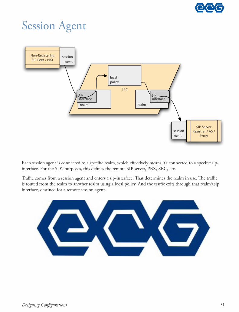
Each session agent is connected to a speci!c realm, which e"ectively means it’s connected to a speci!c sip-interface. For the SD’s purposes, this de!nes the remote SIP server, PBX, SBC, etc.
Tra#c comes from a session agent and enters a sip-interface. $at determines the realm in use. $e tra#c is routed from the realm to another realm using a local policy. And the tra#c exits through that realm’s sip interface, destined for a remote session agent.
Session Agent
��
� ���
�����������
� ���
������� ����
������� ����
� ������� ��
��� �� �� ��������������
�����
� ������� ��
����� ���� �������� ������
81

Acme Packet® Boot Camp
ActivitiesReference !le show_support_info_example_1.txt:
1. What is the busiest process on this SD?
2. What software version is this SD running? (show version image)
3. Suppose this SD tries is trying to route a call to 10.1.45.241 through the realm PLS-Fredijohnx; the calls are failing. Why?
4. How many UDP ports are assigned to most of the steering pools? How many calls could those steering pools therefore support? Hint: even numbered port for RTP, odd numbered port for RTCP.
5. How many NOTIFY messages per second are traversing this SD?
6. How many SUBSCRIBE messages per second are traversing this SD?
7. "e “MBC Errors” table shows problems with media #ows. Suppose that periodically calls have no working audio, or only one way audio. Does anything in the MBC statistics reveal a possibly cause?
8. How many SIP endpoints are registered?
9. How many registered SIP endpoints are behind a NAT device?
10. How many invalid SIP messages have been sent in the past period? What rate of invalid messages per second does that constitute?
11. "e Core server is receiving around 5 SIP SUBSCRIBE messages per second that are failing. Find the failures in the “show sipd” output, and explain which value can be used to detect these failures. What SIP response code is the core server returning?
12. Calculate the SD’s e$ciency. How many INVITE-request-per-second does this SD support for each CPU-utilization-percentage-point? E.g., if the SD has 50 INVITEs per second during a period where the CPU utilization is 10%, then the rate would be 5 INVITES-per-second-per-CPU-percentage-point, or 5 IPS/%. Subtract o% any utilization due to CLI processes (names like “tCli” and “tCliTnet2”).
13. Does this service provider have QoS enabled properly for its SIP peerings?
14. To which IP address and port should SIP registering devices send their registrations?
15. What would happen if an attacker #ooded SIP INVITEs toward 216.19.148.52? Would the SD automatically promote or demote or deny the tra$c? Would a sustained load of tra$c a%ect the SD’s CPU?
16. How many signaling bytes per second can be sent to 10.97.230.46, assuming that no other tra$c is being sent to the SD? (I.e., determine which realm this is a part of, then the access-control trust level tra$c would be a part of, then in the media manager determine the total amount of signaling tra$c allowed, and what part of that?
176

Operational Troubleshooting
17. !is con"guration shows another example way of using the from-address in the local-policy. However, this is not the Acme-Packet-Recommended approach. Can you "nd this method and describe how it is used?
18. What DSCP values are used on SIP signaling and RTP media in this SD’s con"guration?
Reference "le show_support_info_example_2.txt:
19. Calculate this SD’s IPS/%.
20. How many sessions are active on this SD?
21. How many registrations are active on this SD?
177