Embed Size (px)
DESCRIPTION
Voice Port Config
Citation preview

Cisco IOS Voice Port Configuration GuideRelease 12.4T
Americas HeadquartersCisco Systems, Inc.170 West Tasman DriveSan Jose, CA 95134-1706 USAhttp://www.cisco.comTel: 408 526-4000
800 553-NETS (6387)Fax: 408 527-0883

THE SPECIFICATIONS AND INFORMATION REGARDING THE PRODUCTS IN THIS MANUAL ARE SUBJECT TO CHANGE WITHOUT NOTICE. ALL STATEMENTS, INFORMATION, AND RECOMMENDATIONS IN THIS MANUAL ARE BELIEVED TO BE ACCURATE BUT ARE PRESENTED WITHOUT WARRANTY OF ANY KIND, EXPRESS OR IMPLIED. USERS MUST TAKE FULL RESPONSIBILITY FOR THEIR APPLICATION OF ANY PRODUCTS.
THE SOFTWARE LICENSE AND LIMITED WARRANTY FOR THE ACCOMPANYING PRODUCT ARE SET FORTH IN THE INFORMATION PACKET THAT SHIPPED WITH THE PRODUCT AND ARE INCORPORATED HEREIN BY THIS REFERENCE. IF YOU ARE UNABLE TO LOCATE THE SOFTWARE LICENSE OR LIMITED WARRANTY, CONTACT YOUR CISCO REPRESENTATIVE FOR A COPY.
The Cisco implementation of TCP header compression is an adaptation of a program developed by the University of California, Berkeley (UCB) as part of UCB’s public domain version of the UNIX operating system. All rights reserved. Copyright © 1981, Regents of the University of California.
NOTWITHSTANDING ANY OTHER WARRANTY HEREIN, ALL DOCUMENT FILES AND SOFTWARE OF THESE SUPPLIERS ARE PROVIDED “AS IS” WITH ALL FAULTS. CISCO AND THE ABOVE-NAMED SUPPLIERS DISCLAIM ALL WARRANTIES, EXPRESSED OR IMPLIED, INCLUDING, WITHOUT LIMITATION, THOSE OF MERCHANTABILITY, FITNESS FOR A PARTICULAR PURPOSE AND NONINFRINGEMENT OR ARISING FROM A COURSE OF DEALING, USAGE, OR TRADE PRACTICE.
IN NO EVENT SHALL CISCO OR ITS SUPPLIERS BE LIABLE FOR ANY INDIRECT, SPECIAL, CONSEQUENTIAL, OR INCIDENTAL DAMAGES, INCLUDING, WITHOUT LIMITATION, LOST PROFITS OR LOSS OR DAMAGE TO DATA ARISING OUT OF THE USE OR INABILITY TO USE THIS MANUAL, EVEN IF CISCO OR ITS SUPPLIERS HAVE BEEN ADVISED OF THE POSSIBILITY OF SUCH DAMAGES.
CCDE, CCENT, Cisco Eos, Cisco Lumin, Cisco Nexus, Cisco StadiumVision, Cisco TelePresence, the Cisco logo, DCE, and Welcome to the Human Network are trademarks; Changing the Way We Work, Live, Play, and Learn and Cisco Store are service marks; and Access Registrar, Aironet, AsyncOS, Bringing the Meeting To You, Catalyst, CCDA, CCDP, CCIE, CCIP, CCNA, CCNP, CCSP, CCVP, Cisco, the Cisco Certified Internetwork Expert logo, Cisco IOS, Cisco Press, Cisco Systems, Cisco Systems Capital, the Cisco Systems logo, Cisco Unity, Collaboration Without Limitation, EtherFast, EtherSwitch, Event Center, Fast Step, Follow Me Browsing, FormShare, GigaDrive, HomeLink, Internet Quotient, IOS, iPhone, iQ Expertise, the iQ logo, iQ Net Readiness Scorecard, iQuick Study, IronPort, the IronPort logo, LightStream, Linksys, MediaTone, MeetingPlace, MeetingPlace Chime Sound, MGX, Networkers, Networking Academy, Network Registrar, PCNow, PIX, PowerPanels, ProConnect, ScriptShare, SenderBase, SMARTnet, Spectrum Expert, StackWise, The Fastest Way to Increase Your Internet Quotient, TransPath, WebEx, and the WebEx logo are registered trademarks of Cisco Systems, Inc. and/or its affiliates in the United States and certain other countries.
All other trademarks mentioned in this document or Website are the property of their respective owners. The use of the word partner does not imply a partnership relationship between Cisco and any other company. (0807R)
Any Internet Protocol (IP) addresses used in this document are not intended to be actual addresses. Any examples, command display output, and figures included in the document are shown for illustrative purposes only. Any use of actual IP addresses in illustrative content is unintentional and coincidental.
Cisco IOS Voice Port Configuration Guide © 2008 Cisco Systems, Inc. All rights reserved.

i
About Cisco IOS and Cisco IOS XE Software Documentation
Last updated: August 6, 2008
This document describes the objectives, audience, conventions, and organization used in Cisco IOS and Cisco IOS XE software documentation, collectively referred to in this document as Cisco IOS documentation. Also included are resources for obtaining technical assistance, additional documentation, and other information from Cisco. This document is organized into the following sections:
• Documentation Objectives, page i
• Audience, page i
• Documentation Conventions, page ii
• Documentation Organization, page iii
• Additional Resources and Documentation Feedback, page xi
Documentation ObjectivesCisco IOS documentation describes the tasks and commands available to configure and maintain Cisco networking devices.
AudienceThe Cisco IOS documentation set is i ntended for users who configure and maintain Cisco networking devices (such as routers and switches) but who may not be familiar with the configuration and maintenance tasks, the relationship among tasks, or the Cisco IOS commands necessary to perform particular tasks. The Cisco IOS documentation set is also intended for those users experienced with Cisco IOS who need to know about new features, new configuration options, and new software characteristics in the current Cisco IOS release.

About Cisco IOS and Cisco IOS XE Software DocumentationDocumentation Conventions
ii
Documentation ConventionsIn Cisco IOS documentation, the term router may be used to refer to various Cisco products; for example, routers, access servers, and switches. These and other networking devices that support Cisco IOS software are shown interchangeably in examples and are used only for illustrative purposes. An example that shows one product does not necessarily mean that other products are not supported.
This section includes the following topics:
• Typographic Conventions, page ii
• Command Syntax Conventions, page ii
• Software Conventions, page iii
• Reader Alert Conventions, page iii
Typographic ConventionsCisco IOS documentation uses the following typographic conventions:
Command Syntax ConventionsCisco IOS documentation uses the following command syntax conventions:
Convention Description
^ or Ctrl Both the ^ symbol and Ctrl represent the Control (Ctrl) key on a keyboard. For example, the key combination ^D or Ctrl-D means that you hold down the Control key while you press the D key. (Keys are indicated in capital letters but are not case sensitive.)
string A string is a nonquoted set of characters shown in italics. For example, when setting a Simple Network Management Protocol (SNMP) community string to public, do not use quotation marks around the string; otherwise, the string will include the quotation marks.
Convention Description
bold Bold text indicates commands and keywords that you enter as shown.
italic Italic text indicates arguments for which you supply values.
[x] Square brackets enclose an optional keyword or argument.
| A vertical line, called a pipe, indicates a choice within a set of keywords or arguments.
[x | y] Square brackets enclosing keywords or arguments separated by a pipe indicate an optional choice.
{x | y} Braces enclosing keywords or arguments separated by a pipe indicate a required choice.
[x {y | z}] Braces and a pipe within square brackets indicate a required choice within an optional element.

About Cisco IOS and Cisco IOS XE Software DocumentationDocumentation Organization
iii
Software ConventionsCisco IOS uses the following program code conventions:
Reader Alert ConventionsThe Cisco IOS documentation set uses the following conventions for reader alerts:
Caution Means reader be careful. In this situation, you might do something that could result in equipment damage or loss of data.
Note Means reader take note. Notes contain helpful suggestions or references to material not covered in the manual.
Timesaver Means the described action saves time. You can save time by performing the action described in the paragraph.
Documentation OrganizationThis section describes the Cisco IOS documentation set, how it is organized, and how to access it on Cisco.com. Included are lists of configuration guides, command references, and supplementary references and resources that make up the documentation set. The following topics are included:
• Cisco IOS Documentation Set, page iv
• Cisco IOS Documentation on Cisco.com, page iv
• Configuration Guides, Command References, and Supplementary Resources, page v
Convention Description
Courier font Courier font is used for information that is displayed on a PC or terminal screen.
Bold Courier font Bold Courier font indicates text that the user must enter.
< > Angle brackets enclose text that is not displayed, such as a password. Angle brackets also are used in contexts in which the italic font style is not supported; for example, ASCII text.
! An exclamation point at the beginning of a line indicates that the text that follows is a comment, not a line of code. An exclamation point is also displayed by Cisco IOS software for certain processes.
[ ] Square brackets enclose default responses to system prompts.

About Cisco IOS and Cisco IOS XE Software DocumentationDocumentation Organization
iv
Cisco IOS Documentation SetCisco IOS documentation consists of the following:
• Release notes and caveats provide information about platform, technology, and feature support for a release and describe severity 1 (catastrophic), severity 2 (severe), and severity 3 (moderate) defects in released Cisco IOS code. Review release notes before other documents to learn whether or not updates have been made to a feature.
• Sets of configuration guides and command references organized by technology and published for each standard Cisco IOS release.
– Configuration guides—Compilations of documents that provide informational and task-oriented descriptions of Cisco IOS features.
– Command references—Compilations of command pages that provide detailed information about the commands used in the Cisco IOS features and processes that make up the related configuration guides. For each technology, there is a single command reference that covers all Cisco IOS releases and that is updated at each standard release.
• Lists of all the commands in a specific release and all commands that are new, modified, removed, or replaced in the release.
• Command reference book for debug commands. Command pages are listed in alphabetical order.
• Reference book for system messages for all Cisco IOS releases.
Cisco IOS Documentation on Cisco.comThe following sections describe the documentation organization and how to access various document types.
Use Cisco Feature Navigator to find information about platform support and Cisco IOS and Catalyst OS software image support. To access Cisco Feature Navigator, go to http://www.cisco.com/go/cfn. An account on Cisco.com is not required.
New Features List
The New Features List for each release provides a list of all features in the release with hyperlinks to the feature guides in which they are documented.
Feature Guides
Cisco IOS features are documented in feature guides. Feature guides describe one feature or a group of related features that are supported on many different software releases and platforms. Your Cisco IOS software release or platform may not support all the features documented in a feature guide. See the Feature Information table at the end of the feature guide for information about which features in that guide are supported in your software release.
Configuration Guides
Configuration guides are provided by technology and release and comprise a set of individual feature guides relevant to the release and technology.
About Cisco IOS and Cisco IOS XE Software DocumentationDocumentation Organization
v
Command References
Command reference books describe Cisco IOS commands that are supported in many different software releases and on many different platforms. The books are provided by technology. For information about all Cisco IOS commands, use the Command Lookup Tool at http://tools.cisco.com/Support/CLILookup or the Cisco IOS Master Command List, All Releases, at http://www.cisco.com/en/US/docs/ios/mcl/all_release/all_mcl.html.
Cisco IOS Supplementary Documents and Resources
Supplementary documents and resources are listed in Table 2 on page xi.
Configuration Guides, Command References, and Supplementary ResourcesTable 1 lists, in alphabetical order, Cisco IOS and Cisco IOS XE software configuration guides and command references, including brief descriptions of the contents of the documents. The Cisco IOS command references are comprehensive, meaning that they include commands for both Cisco IOS software and Cisco IOS XE software, for all releases. The configuration guides and command references support many different software releases and platforms. Your Cisco IOS software release or platform may not support all these technologies.
For additional information about configuring and operating specific networking devices, go to the Product Support area of Cisco.com at http://www.cisco.com/web/psa/products/index.html.
Table 2 lists documents and resources that supplement the Cisco IOS software configuration guides and command references. These supplementary resources include release notes and caveats; master command lists; new, modified, removed, and replaced command lists; system messages; and the debug command reference.
Table 1 Cisco IOS and Cisco IOS XE Configuration Guides and Command References
Configuration Guide and Command Reference Titles Features/Protocols/Technologies
Cisco IOS AppleTalk Configuration Guide
Cisco IOS XE AppleTalk Configuration Guide
Cisco IOS AppleTalk Command Reference
AppleTalk protocol.
Cisco IOS Asynchronous Transfer Mode Configuration Guide
Cisco IOS Asynchronous Transfer Mode Command Reference
LAN ATM, multiprotocol over ATM (MPoA), and WAN ATM.
About Cisco IOS and Cisco IOS XE Software DocumentationDocumentation Organization
vi
Cisco IOS Bridging and IBM Networking Configuration Guide
Cisco IOS Bridging Command Reference
Cisco IOS IBM Networking Command Reference
• Transparent and source-route transparent (SRT) bridging, source-route bridging (SRB), Token Ring Inter-Switch Link (TRISL), and token ring route switch module (TRRSM).
• Data-link switching plus (DLSw+), serial tunnel (STUN), block serial tunnel (BSTUN); logical link control, type 2 (LLC2), synchronous data link control (SDLC); IBM Network Media Translation, including Synchronous Data Logical Link Control (SDLLC) and qualified LLC (QLLC); downstream physical unit (DSPU), Systems Network Architecture (SNA) service point, SNA frame relay access, advanced peer-to-peer networking (APPN), native client interface architecture (NCIA) client/server topologies, and IBM Channel Attach.
Cisco IOS Broadband and DSL Configuration Guide
Cisco IOS XE Broadband and DSL Configuration Guide
Cisco IOS Broadband and DSL Command Reference
Point-to-Point Protocol (PPP) over ATM (PPPoA) and PPP over Ethernet (PPPoE).
Cisco IOS Carrier Ethernet Configuration Guide
Cisco IOS Carrier Ethernet Command Reference
Connectivity fault management (CFM), Ethernet Local Management Interface (ELMI), IEEE 802.3ad link bundling, Link Layer Discovery Protocol (LLDP), media endpoint discovery (MED), and operations, administration, and maintenance (OAM).
Cisco IOS Configuration Fundamentals Configuration Guide
Cisco IOS XE Configuration Fundamentals Configuration Guide
Cisco IOS Configuration Fundamentals Command Reference
Autoinstall, Setup, Cisco IOS command-line interface (CLI), Cisco IOS file system (IFS), Cisco IOS web browser user interface (UI), basic file transfer services, and file management.
Cisco IOS DECnet Configuration Guide
Cisco IOS XE DECnet Configuration Guide
Cisco IOS DECnet Command Reference
DECnet protocol.
Cisco IOS Dial Technologies Configuration Guide
Cisco IOS XE Dial Technologies Configuration Guide
Cisco IOS Dial Technologies Command Reference
Asynchronous communications, dial backup, dialer technology, dial-in terminal services and AppleTalk remote access (ARA), large scale dialout, dial-on-demand routing, dialout, modem and resource pooling, ISDN, multilink PPP (MLP), PPP, virtual private dialup network (VPDN).
Cisco IOS Flexible NetFlow Configuration Guide
Cisco IOS Flexible NetFlow Command Reference
Flexible NetFlow.
Table 1 Cisco IOS and Cisco IOS XE Configuration Guides and Command References (continued)
Configuration Guide and Command Reference Titles Features/Protocols/Technologies

About Cisco IOS and Cisco IOS XE Software DocumentationDocumentation Organization
vii
Cisco IOS H.323 Configuration Guide Gatekeeper enhancements for managed voice services, Gatekeeper Transaction Message Protocol, gateway codec order preservation and shutdown control, H.323 dual tone multifrequency relay, H.323 version 2 enhancements, Network Address Translation (NAT) support of H.323 v2 Registration, Admission, and Status (RAS) protocol, tokenless call authorization, and VoIP gateway trunk and carrier-based routing.
Cisco IOS High Availability Configuration Guide
Cisco IOS XE High Availability Configuration Guide
Cisco IOS High Availability Command Reference
A variety of High Availability (HA) features and technologies that are available for different network segments (from enterprise access to service provider core) to facilitate creation of end-to-end highly available networks. Cisco IOS HA features and technologies can be categorized in three key areas: system-level resiliency, network-level resiliency, and embedded management for resiliency.
Cisco IOS Integrated Session Border Controller Command Reference
A VoIP-enabled device that is deployed at the edge of networks. An SBC is a toolkit of functions, such as signaling interworking, network hiding, security, and quality of service (QoS).
Cisco IOS Intelligent Service Gateway Configuration Guide
Cisco IOS Intelligent Service Gateway Command Reference
Subscriber identification, service and policy determination, session creation, session policy enforcement, session life-cycle management, accounting for access and service usage, session state monitoring.
Cisco IOS Interface and Hardware Component Configuration Guide
Cisco IOS XE Interface and Hardware Component Configuration Guide
Cisco IOS Interface and Hardware Component Command Reference
LAN interfaces, logical interfaces, serial interfaces, virtual interfaces, and interface configuration.
Cisco IOS IP Addressing Services Configuration Guide
Cisco IOS XE Addressing Services Configuration Guide
Cisco IOS IP Addressing Services Command Reference
Address Resolution Protocol (ARP), Network Address Translation (NAT), Domain Name System (DNS), Dynamic Host Configuration Protocol (DHCP), and Next Hop Address Resolution Protocol (NHRP).
Cisco IOS IP Application Services Configuration Guide
Cisco IOS XE IP Application Services Configuration Guide
Cisco IOS IP Application Services Command Reference
Enhanced Object Tracking (EOT), Gateway Load Balancing Protocol (GLBP), Hot Standby Router Protocol (HSRP), IP Services, Server Load Balancing (SLB), Stream Control Transmission Protocol (SCTP), TCP, Web Cache Communication Protocol (WCCP), User Datagram Protocol (UDP), and Virtual Router Redundancy Protocol (VRRP).
Cisco IOS IP Mobility Configuration Guide
Cisco IOS IP Mobility Command Reference
Mobile ad hoc networks (MANet) and Cisco mobile networks.
Cisco IOS IP Multicast Configuration Guide
Cisco IOS XE IP Multicast Configuration Guide
Cisco IOS IP Multicast Command Reference
Protocol Independent Multicast (PIM) sparse mode (PIM-SM), bidirectional PIM (bidir-PIM), Source Specific Multicast (SSM), Multicast Source Discovery Protocol (MSDP), Internet Group Management Protocol (IGMP), and Multicast VPN (MVPN).
Table 1 Cisco IOS and Cisco IOS XE Configuration Guides and Command References (continued)
Configuration Guide and Command Reference Titles Features/Protocols/Technologies

About Cisco IOS and Cisco IOS XE Software DocumentationDocumentation Organization
viii
Cisco IOS IP Routing Protocols Configuration Guide
Cisco IOS XE IP Routing Protocols Configuration Guide
Cisco IOS IP Routing Protocols Command Reference
Border Gateway Protocol (BGP), multiprotocol BGP, multiprotocol BGP extensions for IP multicast, bidirectional forwarding detection (BFD), Enhanced Interior Gateway Routing Protocol (EIGRP), Interior Gateway Routing Protocol (IGRP), Intermediate System-to-Intermediate System (IS-IS), on-demand routing (ODR), Open Shortest Path First (OSPF), and Routing Information Protocol (RIP).
Cisco IOS IP SLAs Configuration Guide
Cisco IOS XE IP SLAs Configuration Guide
Cisco IOS IP SLAs Command Reference
Cisco IOS IP Service Level Agreements (IP SLAs).
Cisco IOS IP Switching Configuration Guide
Cisco IOS XE IP Switching Configuration Guide
Cisco IOS IP Switching Command Reference
Cisco Express Forwarding, fast switching, and Multicast Distributed Switching (MDS).
Cisco IOS IPv6 Configuration Guide
Cisco IOS XE IPv6 Configuration Guide
Cisco IOS IPv6 Command Reference
For IPv6 features, protocols, and technologies, go to the IPv6 “Start Here” document at the following URL:
http://www.cisco.com/en/US/docs/ios/ipv6/configuration/ guide/ip6-roadmap.html
Cisco IOS ISO CLNS Configuration Guide
Cisco IOS XE ISO CLNS Configuration Guide
Cisco IOS ISO CLNS Command Reference
ISO connectionless network service (CLNS).
Cisco IOS LAN Switching Configuration Guide
Cisco IOS XE LAN Switching Configuration Guide
Cisco IOS LAN Switching Command Reference
VLANs, Inter-Switch Link (ISL) encapsulation, IEEE 802.10 encapsulation, IEEE 802.1Q encapsulation, and multilayer switching (MLS).
Cisco IOS Mobile Wireless Gateway GPRS Support Node Configuration Guide
Cisco IOS Mobile Wireless Gateway GPRS Support Node Command Reference
Cisco IOS Gateway GPRS Support Node (GGSN) in a 2.5-generation general packet radio service (GPRS) and 3-generation universal mobile telecommunication system (UMTS) network.
Cisco IOS Mobile Wireless Home Agent Configuration Guide
Cisco IOS Mobile Wireless Home Agent Command Reference
Cisco Mobile Wireless Home Agent, an anchor point for mobile terminals for which mobile IP or proxy mobile IP services are provided.
Cisco IOS Mobile Wireless Packet Data Serving Node Configuration Guide
Cisco IOS Mobile Wireless Packet Data Serving Node Command Reference
Cisco Packet Data Serving Node (PDSN), a wireless gateway that is between the mobile infrastructure and standard IP networks and that enables packet data services in a code division multiple access (CDMA) environment.
Cisco IOS Mobile Wireless Radio Access Networking Configuration Guide
Cisco IOS Mobile Wireless Radio Access Networking Command Reference
Cisco IOS radio access network products.
Table 1 Cisco IOS and Cisco IOS XE Configuration Guides and Command References (continued)
Configuration Guide and Command Reference Titles Features/Protocols/Technologies
About Cisco IOS and Cisco IOS XE Software DocumentationDocumentation Organization
ix
Cisco IOS Multiprotocol Label Switching Configuration Guide
Cisco IOS XE Multiprotocol Label Switching Configuration Guide
Cisco IOS Multiprotocol Label Switching Command Reference
MPLS Label Distribution Protocol (LDP), MPLS Layer 2 VPNs, MPLS Layer 3 VPNs, MPLS Traffic Engineering (TE), and MPLS Embedded Management (EM) and MIBs.
Cisco IOS Multi-Topology Routing Configuration Guide
Cisco IOS Multi-Topology Routing Command Reference
Unicast and multicast topology configurations, traffic classification, routing protocol support, and network management support.
Cisco IOS NetFlow Configuration Guide
Cisco IOS XE NetFlow Configuration Guide
Cisco IOS NetFlow Command Reference
Network traffic data analysis, aggregation caches, export features.
Cisco IOS Network Management Configuration Guide
Cisco IOS XE Network Management Configuration Guide
Cisco IOS Network Management Command Reference
Basic system management; system monitoring and logging; troubleshooting, logging, and fault management; Cisco Discovery Protocol; Cisco IOS Scripting with Tool Control Language (Tcl); Cisco networking services (CNS); DistributedDirector; Embedded Event Manager (EEM); Embedded Resource Manager (ERM); Embedded Syslog Manager (ESM); HTTP; Remote Monitoring (RMON); SNMP; and VPN Device Manager Client for Cisco IOS Software (XSM Configuration).
Cisco IOS Novell IPX Configuration Guide
Cisco IOS XE Novell IPX Configuration Guide
Cisco IOS Novell IPX Command Reference
Novell Internetwork Packet Exchange (IPX) protocol.
Cisco IOS Optimized Edge Routing Configuration Guide
Cisco IOS Optimized Edge Routing Command Reference
Optimized edge routing (OER) monitoring, policy configuration, routing control, logging and reporting, and VPN IPsec/generic routing encapsulation (GRE) tunnel interface optimization.
Cisco IOS Quality of Service Solutions Configuration Guide
Cisco IOS XE Quality of Service Solutions Configuration Guide
Cisco IOS Quality of Service Solutions Command Reference
Class-based weighted fair queuing (CBWFQ), custom queuing, distributed traffic shaping (DTS), generic traffic shaping (GTS), IP- to-ATM class of service (CoS), low latency queuing (LLQ), modular QoS CLI (MQC), Network-Based Application Recognition (NBAR), priority queuing, Security Device Manager (SDM), Multilink PPP (MLPPP) for QoS, header compression, AutoQoS, QoS features for voice, Resource Reservation Protocol (RSVP), weighted fair queuing (WFQ), and weighted random early detection (WRED).
Cisco IOS Security Configuration Guide
Cisco IOS XE Security Configuration Guide
Cisco IOS Security Command Reference
Access control lists (ACLs), authentication, authorization, and accounting (AAA), firewalls, IP security and encryption, neighbor router authentication, network access security, network data encryption with router authentication, public key infrastructure (PKI), RADIUS, TACACS+, terminal access security, and traffic filters.
Table 1 Cisco IOS and Cisco IOS XE Configuration Guides and Command References (continued)
Configuration Guide and Command Reference Titles Features/Protocols/Technologies

About Cisco IOS and Cisco IOS XE Software DocumentationDocumentation Organization
x
Cisco IOS Service Selection Gateway Configuration Guide
Cisco IOS Service Selection Gateway Command Reference
Subscriber authentication, service access, and accounting.
Cisco IOS Software Activation Configuration Guide
Cisco IOS Software Activation Command Reference
An orchestrated collection of processes and components to activate Cisco IOS software feature sets by obtaining and validating Cisco software licenses.
Cisco IOS Software Modularity Installation and Configuration Guide
Cisco IOS Software Modularity Command Reference
Installation and basic configuration of software modularity images, including installations on single and dual route processors, installation rollbacks, software modularity binding, software modularity processes and patches.
Cisco IOS Terminal Services Configuration Guide
Cisco IOS Terminal Services Command Reference
Cisco IOS XE Terminal Services Command Reference
DEC, local-area transport (LAT), and X.25 packet assembler/disassembler (PAD).
Cisco IOS Virtual Switch Command Reference Virtual switch redundancy, high availability, and packet handling; converting between standalone and virtual switch modes; virtual switch link (VSL); Virtual Switch Link Protocol (VSLP).
Note For information about virtual switch configuration, refer to the product-specific software configuration information for the Cisco Catalyst 6500 series switch or for the Metro Ethernet 6500 series switch.
Cisco IOS Voice Configuration Library
Cisco IOS Voice Command Reference
Cisco IOS support for voice call control protocols, interoperability, physical and virtual interface management, and troubleshooting. The library includes documentation for IP telephony applications.
Cisco IOS VPDN Configuration Guide
Cisco IOS XE VPDN Configuration Guide
Cisco IOS VPDN Command Reference
Layer 2 Tunneling Protocol (L2TP) dial-out load balancing and redundancy, L2TP extended failover, L2TP security VPDN, multihop by Dialed Number Identification Service (DNIS), timer and retry enhancements for L2TP and Layer 2 Forwarding (L2F), RADIUS Attribute 82: tunnel assignment ID, shell-based authentication of VPDN users, tunnel authentication via RADIUS on tunnel terminator.
Cisco IOS Wide-Area Networking Configuration Guide
Cisco IOS XE Wide-Area Networking Configuration Guide
Cisco IOS Wide-Area Networking Command Reference
Frame Relay, Layer 2 Tunneling Protocol Version 3 (L2TPv3), Link Access Procedure, Balanced (LAPB), Switched Multimegabit Data Service (SMDS), and X.25.
Cisco IOS Wireless LAN Configuration Guide
Cisco IOS Wireless LAN Command Reference
Broadcast key rotation, IEEE 802.11x support, IEEE 802.1x authenticator, IEEE 802.1x local authentication service for Extensible Authentication Protocol-Flexible Authentication via Secure Tunneling (EAP-FAST), Multiple Basic Service Set ID (BSSID), Wi-Fi Multimedia (WMM) required elements, and Wi-Fi Protected Access (WPA).
Table 1 Cisco IOS and Cisco IOS XE Configuration Guides and Command References (continued)
Configuration Guide and Command Reference Titles Features/Protocols/Technologies

About Cisco IOS and Cisco IOS XE Software DocumentationAdditional Resources and Documentation Feedback
xi
Additional Resources and Documentation FeedbackWhat’s New in Cisco Product Documentation is published monthly and describes all new and revised Cisco technical documentation. The What’s New in Cisco Product Documentation publication also provides information about obtaining the following resources:
• Technical documentation
• Cisco product security overview
• Product alerts and field notices
• Technical assistance
Cisco IOS technical documentation includes embedded feedback forms where you can rate documents and provide suggestions for improvement. Your feedback helps us improve our documentation.
Table 2 Cisco IOS Supplementary Documents and Resources
Document Title Description
Cisco IOS Master Command List, All Releases Alphabetical list of all the commands documented in all Cisco IOS releases.
Cisco IOS New, Modified, Removed, and Replaced Commands
List of all the new, modified, removed, and replaced commands for a Cisco IOS release.
Cisco IOS Software System Messages List of Cisco IOS system messages and descriptions. System messages may indicate problems with your system; be informational only; or may help diagnose problems with communications lines, internal hardware, or the system software.
Cisco IOS Debug Command Reference Alphabetical list of debug commands including brief descriptions of use, command syntax, and usage guidelines.
Release Notes and Caveats Information about new and changed features, system requirements, and other useful information about specific software releases; information about defects in specific Cisco IOS software releases.
MIBs Files used for network monitoring. To locate and download MIBs for selected platforms, Cisco IOS releases, and feature sets, use Cisco MIB Locator at the following URL:
http://www.cisco.com/go/mibs
RFCs Standards documents maintained by the Internet Engineering Task Force (IETF) that Cisco IOS documentation references where applicable. The full text of referenced RFCs may be obtained at the following URL:
http://www.rfc-editor.org/

About Cisco IOS and Cisco IOS XE Software DocumentationAdditional Resources and Documentation Feedback
xii
CCDE, CCENT, Cisco Eos, Cisco Lumin, Cisco Nexus, Cisco StadiumVision, Cisco TelePresence, the Cisco logo, DCE, and Welcome to the Human Network are trademarks; Changing the Way We Work, Live, Play, and Learn and Cisco Store are service marks; and Access Registrar, Aironet, AsyncOS, Bringing the Meeting To You, Catalyst, CCDA, CCDP, CCIE, CCIP, CCNA, CCNP, CCSP, CCVP, Cisco, the Cisco Certified Internetwork Expert logo, Cisco IOS, Cisco Press, Cisco Systems, Cisco Systems Capital, the Cisco Systems logo, Cisco Unity, Collaboration Without Limitation, EtherFast, EtherSwitch, Event Center, Fast Step, Follow Me Browsing, FormShare, GigaDrive, HomeLink, Internet Quotient, IOS, iPhone, iQ Expertise, the iQ logo, iQ Net Readiness Scorecard, iQuick Study, IronPort, the IronPort logo, LightStream, Linksys, MediaTone, MeetingPlace, MeetingPlace Chime Sound, MGX, Networkers, Networking Academy, Network Registrar, PCNow, PIX, PowerPanels, ProConnect, ScriptShare, SenderBase, SMARTnet, Spectrum Expert, StackWise, The Fastest Way to Increase Your Internet Quotient, TransPath, WebEx, and the WebEx logo are registered trademarks of Cisco Systems, Inc. and/or its affiliates in the United States and certain other countries.
All other trademarks mentioned in this document or Website are the property of their respective owners. The use of the word partner does not imply a partnership relationship between Cisco and any other company. (0807R) Any Internet Protocol (IP) addresses used in this document are not intended to be actual addresses. Any examples, command display output, and figures included in the document are shown for illustrative purposes only. Any use of actual IP addresses in illustrative content is unintentional and coincidental. © 2007–2008 Cisco Systems, Inc. All rights reserved.
i
Using the Command-Line Interface in Cisco IOS and Cisco IOS XE Software
Last updated: August 6, 2008
This document provides basic information about the command-line interface (CLI) in Cisco IOS and Cisco IOS XE software and how you can use some of the CLI features. This document contains the following sections:
• Initially Configuring a Device, page i
• Using the CLI, page ii
• Saving Changes to a Configuration, page xii
• Additional Information, page xii
For more information about using the CLI, see the “Using the Cisco IOS Command-Line Interface” section of the Cisco IOS Configuration Fundamentals Configuration Guide.
For information about the software documentation set, see the “About Cisco IOS and Cisco IOS XE Software Documentation” document.
Initially Configuring a DeviceInitially configuring a device varies by platform. For information about performing an initial configuration, see the hardware installation documentation that is provided with the original packaging of the product or go to the Product Support area of Cisco.com at http://www.cisco.com/web/psa/products/index.html.
After you have performed the initial configuration and connected the device to your network, you can configure the device by using the console port or a remote access method, such as Telnet or Secure Shell (SSH), to access the CLI or by using the configuration method provided on the device, such as Security Device Manager.

Using the Command-Line Interface in Cisco IOS and Cisco IOS XE SoftwareUsing the CLI
ii
Changing the Default Settings for a Console or AUX Port
There are only two changes that you can make to a console port and an AUX port:
• Change the port speed with the config-register 0x command. Changing the port speed is not recommended. The well-known default speed is 9600.
• Change the behavior of the port; for example, by adding a password or changing the timeout value.
Note The AUX port on the Route Processor (RP) installed in a Cisco ASR1000 series router does not serve any useful customer purpose and should be accessed only under the advisement of a customer support representative.
Using the CLIThis section describes the following topics:
• Understanding Command Modes, page ii
• Using the Interactive Help Feature, page v
• Understanding Command Syntax, page vi
• Understanding Enable and Enable Secret Passwords, page viii
• Using the Command History Feature, page viii
• Abbreviating Commands, page ix
• Using Aliases for CLI Commands, page ix
• Using the no and default Forms of Commands, page x
• Using the debug Command, page x
• Filtering Output Using Output Modifiers, page x
• Understanding CLI Error Messages, page xi
Understanding Command ModesThe CLI command mode structure is hierarchical, and each mode supports a set of specific commands. This section describes the most common of the many modes that exist.
Table 1 lists common command modes with associated CLI prompts, access and exit methods, and a brief description of how each mode is used.

Using the Command-Line Interface in Cisco IOS and Cisco IOS XE SoftwareUsing the CLI
iii
Table 1 CLI Command Modes
Command Mode
Access Method Prompt Exit Method Mode Usage
User EXEC Log in. Router> Issue the logout or exit command.
• Change terminal settings.
• Perform basic tests.
• Display device status.
Privileged EXEC
From user EXEC mode, issue the enable command.
Router# Issue the disable command or the exit command to return to user EXEC mode.
• Issue show and debug commands.
• Copy images to the device.
• Reload the device.
• Manage device configuration files.
• Manage device file systems.
Global configuration
From privileged EXEC mode, issue the configure terminal command.
Router(config)# Issue the exit command or the end command to return to privileged EXEC mode.
Configure the device.
Interface configuration
From global configuration mode, issue the interface command.
Router(config-if)# Issue the exit command to return to global configuration mode or the end command to return to privileged EXEC mode.
Configure individual interfaces.
Line configuration
From global configuration mode, issue the line vty or line console command.
Router(config-line)# Issue the exit command to return to global configuration mode or the end command to return to privileged EXEC mode.
Configure individual terminal lines.

Using the Command-Line Interface in Cisco IOS and Cisco IOS XE SoftwareUsing the CLI
iv
ROM monitor From privileged EXEC mode, issue the reload command. Press the Break key during the first 60 seconds while the system is booting.
rommon # >
The # symbol represents the line number and increments at each prompt.
Issue the continue command.
• Run as the default operating mode when a valid image cannot be loaded.
• Access the fall-back procedure for loading an image when the device lacks a valid image and cannot be booted.
• Perform password recovery when a CTRL-Break sequence is issued within 60 seconds of a power-on or reload event.
Diagnostic (available only on the Cisco ASR1000 series router)
The router boots or enters diagnostic mode in the following scenarios. When a Cisco IOS process or processes fail, in most scenarios the router will reload.
• A user-configured access policy was configured using the transport-map command, which directed the user into diagnostic mode.
• The router was accessed using an RP auxiliary port.
• A break signal (Ctrl-C, Ctrl-Shift-6, or the send break command) was entered, and the router was configured to enter diagnostic mode when the break signal was received.
Router(diag)# If a Cisco IOS process failure is the reason for entering diagnostic mode, the failure must be resolved and the router must be rebooted to exit diagnostic mode.
If the router is in diagnostic mode because of a transport-map configuration, access the router through another port or using a method that is configured to connect to the Cisco IOS CLI.
If the RP auxiliary port was used to access the router, use another port for access. Accessing the router through the auxiliary port is not useful for customer purposes.
• Inspect various states on the router, including the Cisco IOS state.
• Replace or roll back the configuration.
• Provide methods of restarting the Cisco IOS software or other processes.
• Reboot hardware, such as the entire router, an RP, an ESP, a SIP, a SPA, or possibly other hardware components.
• Transfer files into or off of the router using remote access methods such as FTP, TFTP, and SCP.
Table 1 CLI Command Modes (continued)
Command Mode
Access Method Prompt Exit Method Mode Usage
Using the Command-Line Interface in Cisco IOS and Cisco IOS XE SoftwareUsing the CLI
v
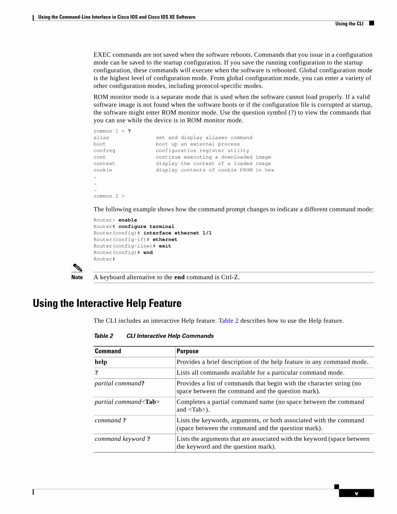
EXEC commands are not saved when the software reboots. Commands that you issue in a configuration mode can be saved to the startup configuration. If you save the running configuration to the startup configuration, these commands will execute when the software is rebooted. Global configuration mode is the highest level of configuration mode. From global configuration mode, you can enter a variety of other configuration modes, including protocol-specific modes.
ROM monitor mode is a separate mode that is used when the software cannot load properly. If a valid software image is not found when the software boots or if the configuration file is corrupted at startup, the software might enter ROM monitor mode. Use the question symbol (?) to view the commands that you can use while the device is in ROM monitor mode.
rommon 1 > ?alias set and display aliases commandboot boot up an external processconfreg configuration register utilitycont continue executing a downloaded imagecontext display the context of a loaded imagecookie display contents of cookie PROM in hex...rommon 2 >
The following example shows how the command prompt changes to indicate a different command mode:
Router> enableRouter# configure terminalRouter(config)# interface ethernet 1/1Router(config-if)# ethernetRouter(config-line)# exitRouter(config)# endRouter#
Note A keyboard alternative to the end command is Ctrl-Z.
Using the Interactive Help FeatureThe CLI includes an interactive Help feature. Table 2 describes how to use the Help feature.
Table 2 CLI Interactive Help Commands
Command Purpose
help Provides a brief description of the help feature in any command mode.
? Lists all commands available for a particular command mode.
partial command? Provides a list of commands that begin with the character string (no space between the command and the question mark).
partial command<Tab> Completes a partial command name (no space between the command and <Tab>).
command ? Lists the keywords, arguments, or both associated with the command (space between the command and the question mark).
command keyword ? Lists the arguments that are associated with the keyword (space between the keyword and the question mark).

Using the Command-Line Interface in Cisco IOS and Cisco IOS XE SoftwareUsing the CLI
vi
The following examples show how to use the help commands:
helpRouter> help
Help may be requested at any point in a command by entering a question mark '?'. If nothing matches, the help list will be empty and you must backup until entering a '?' shows the available options.
Two styles of help are provided:
1. Full help is available when you are ready to enter a command argument (e.g. 'show ?') and describes each possible argument.
2. Partial help is provided when an abbreviated argument is entered and you want to know what arguments match the input (e.g. 'show pr?'.)
?Router# ?Exec commands: access-enable Create a temporary access-List entry access-profile Apply user-profile to interface access-template Create a temporary access-List entry alps ALPS exec commands archive manage archive files<snip>
partial command?Router(config)# zo?zone zone-pair
partial command<Tab>Router(config)# we<Tab> webvpn
command ?Router(config-if)# pppoe ? enable Enable pppoe max-sessions Maximum PPPOE sessions
command keyword ?Router(config-if)# pppoe enable ? group attach a BBA group <cr>
Understanding Command SyntaxCommand syntax is the format in which a command should be entered in the CLI. Commands include the name of the command, keywords, and arguments. Keywords are alphanumeric strings that are used literally. Arguments are placeholders for values that a user must supply. Keywords and arguments may be required or optional.
Specific conventions convey information about syntax and command elements. Table 3 describes these conventions.

Using the Command-Line Interface in Cisco IOS and Cisco IOS XE SoftwareUsing the CLI
vii
The following examples show syntax conventions:
Router(config)# ethernet cfm domain ? WORD domain nameRouter(config)# ethernet cfm domain dname ? level Router(config)# ethernet cfm domain dname level ? <0-7> maintenance level numberRouter(config)# ethernet cfm domain dname level 7 ? <cr>Router(config)# snmp-server file-transfer access-group 10 ? protocol protocol options <cr>Router(config)# logging host ? Hostname or A.B.C.D IP address of the syslog server ipv6 Configure IPv6 syslog serverRouter(config)# snmp-server file-transfer access-group 10 ? protocol protocol options <cr>
Table 3 CLI Syntax Conventions
Symbol/Text Function Notes
< > (angle brackets) Indicate that the option is an argument.
Sometimes arguments are displayed without angle brackets.
A.B.C.D. Indicates that you must enter a dotted decimal IP address.
Angle brackets (< >) are not always used to indicate that an IP address is an argument.
WORD (all capital letters) Indicates that you must enter one word.
Angle brackets (< >) are not always used to indicate that a WORD is an argument.
LINE (all capital letters) Indicates that you must enter more than one word.
Angle brackets (< >) are not always used to indicate that a LINE is an argument.
<cr> (carriage return) Indicates the end of the list of available keywords and argu-ments, and also indicates when keywords and arguments are optional. When <cr> is the only option, you have reached the end of the branch or the end of the command if the command has only one branch.
—
Using the Command-Line Interface in Cisco IOS and Cisco IOS XE SoftwareUsing the CLI
viii
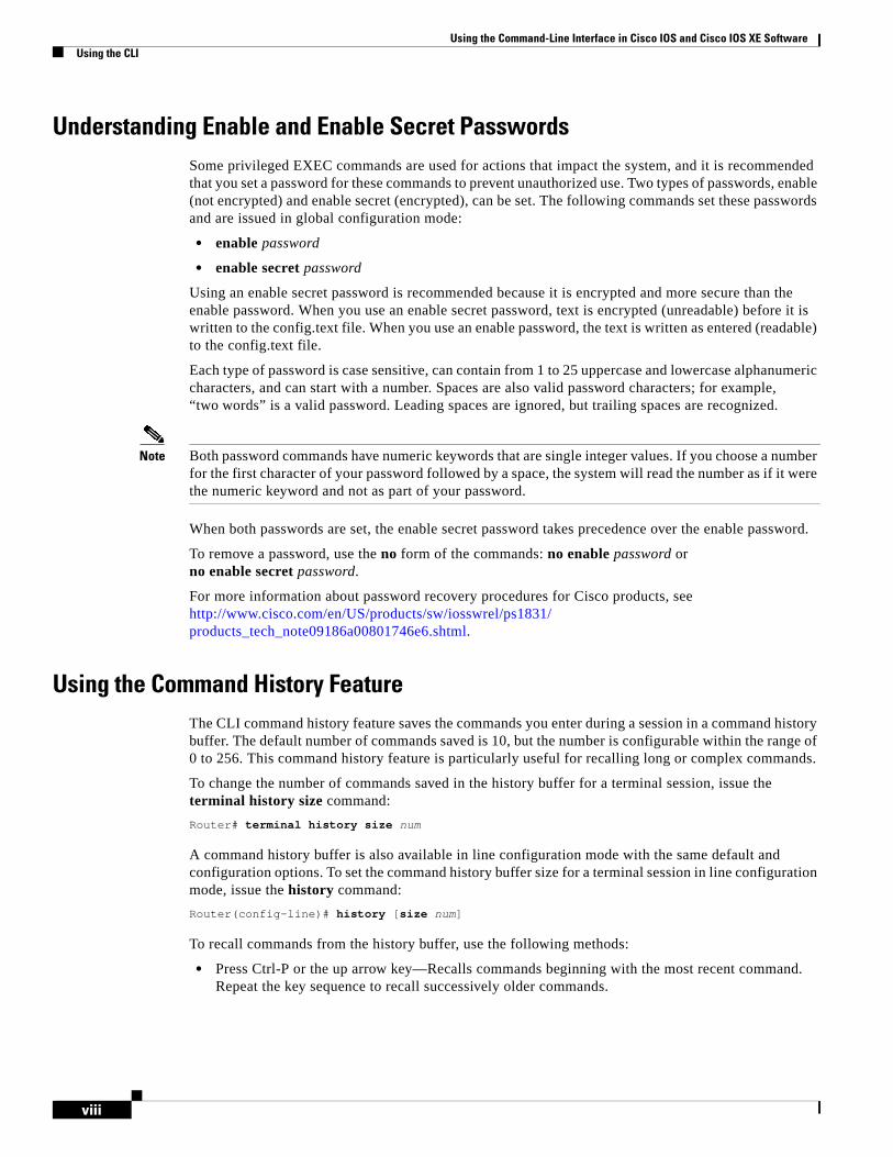
Understanding Enable and Enable Secret PasswordsSome privileged EXEC commands are used for actions that impact the system, and it is recommended that you set a password for these commands to prevent unauthorized use. Two types of passwords, enable (not encrypted) and enable secret (encrypted), can be set. The following commands set these passwords and are issued in global configuration mode:
• enable password
• enable secret password
Using an enable secret password is recommended because it is encrypted and more secure than the enable password. When you use an enable secret password, text is encrypted (unreadable) before it is written to the config.text file. When you use an enable password, the text is written as entered (readable) to the config.text file.
Each type of password is case sensitive, can contain from 1 to 25 uppercase and lowercase alphanumeric characters, and can start with a number. Spaces are also valid password characters; for example, “two words” is a valid password. Leading spaces are ignored, but trailing spaces are recognized.
Note Both password commands have numeric keywords that are single integer values. If you choose a number for the first character of your password followed by a space, the system will read the number as if it were the numeric keyword and not as part of your password.
When both passwords are set, the enable secret password takes precedence over the enable password.
To remove a password, use the no form of the commands: no enable password or no enable secret password.
For more information about password recovery procedures for Cisco products, see http://www.cisco.com/en/US/products/sw/iosswrel/ps1831/ products_tech_note09186a00801746e6.shtml.
Using the Command History FeatureThe CLI command history feature saves the commands you enter during a session in a command history buffer. The default number of commands saved is 10, but the number is configurable within the range of 0 to 256. This command history feature is particularly useful for recalling long or complex commands.
To change the number of commands saved in the history buffer for a terminal session, issue the terminal history size command:
Router# terminal history size num
A command history buffer is also available in line configuration mode with the same default and configuration options. To set the command history buffer size for a terminal session in line configuration mode, issue the history command:
Router(config-line)# history [size num]
To recall commands from the history buffer, use the following methods:
• Press Ctrl-P or the up arrow key—Recalls commands beginning with the most recent command. Repeat the key sequence to recall successively older commands.
Using the Command-Line Interface in Cisco IOS and Cisco IOS XE SoftwareUsing the CLI
ix
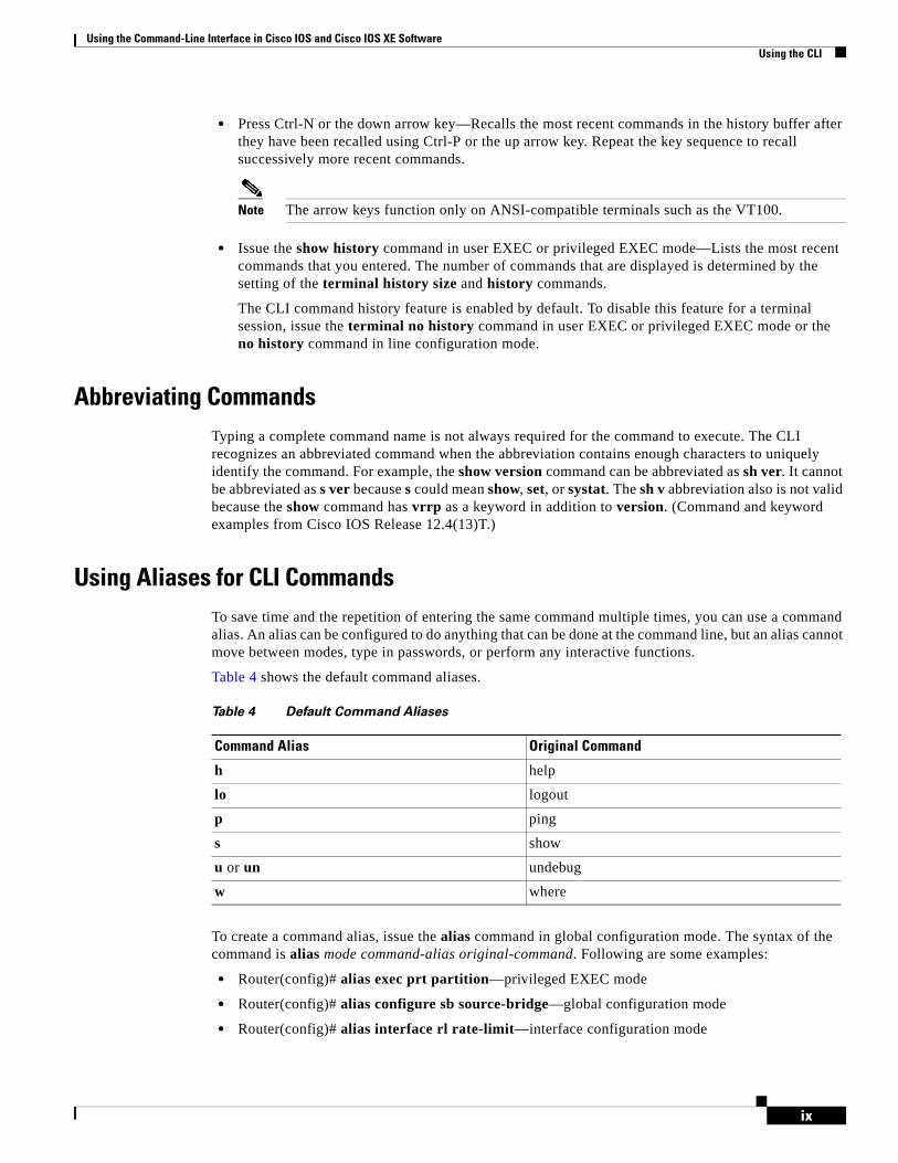
• Press Ctrl-N or the down arrow key—Recalls the most recent commands in the history buffer after they have been recalled using Ctrl-P or the up arrow key. Repeat the key sequence to recall successively more recent commands.
Note The arrow keys function only on ANSI-compatible terminals such as the VT100.
• Issue the show history command in user EXEC or privileged EXEC mode—Lists the most recent commands that you entered. The number of commands that are displayed is determined by the setting of the terminal history size and history commands.
The CLI command history feature is enabled by default. To disable this feature for a terminal session, issue the terminal no history command in user EXEC or privileged EXEC mode or the no history command in line configuration mode.
Abbreviating CommandsTyping a complete command name is not always required for the command to execute. The CLI recognizes an abbreviated command when the abbreviation contains enough characters to uniquely identify the command. For example, the show version command can be abbreviated as sh ver. It cannot be abbreviated as s ver because s could mean show, set, or systat. The sh v abbreviation also is not valid because the show command has vrrp as a keyword in addition to version. (Command and keyword examples from Cisco IOS Release 12.4(13)T.)
Using Aliases for CLI CommandsTo save time and the repetition of entering the same command multiple times, you can use a command alias. An alias can be configured to do anything that can be done at the command line, but an alias cannot move between modes, type in passwords, or perform any interactive functions.
Table 4 shows the default command aliases.
To create a command alias, issue the alias command in global configuration mode. The syntax of the command is alias mode command-alias original-command. Following are some examples:
• Router(config)# alias exec prt partition—privileged EXEC mode
• Router(config)# alias configure sb source-bridge—global configuration mode
• Router(config)# alias interface rl rate-limit—interface configuration mode
Table 4 Default Command Aliases
Command Alias Original Command
h help
lo logout
p ping
s show
u or un undebug
w where
Using the Command-Line Interface in Cisco IOS and Cisco IOS XE SoftwareUsing the CLI
x
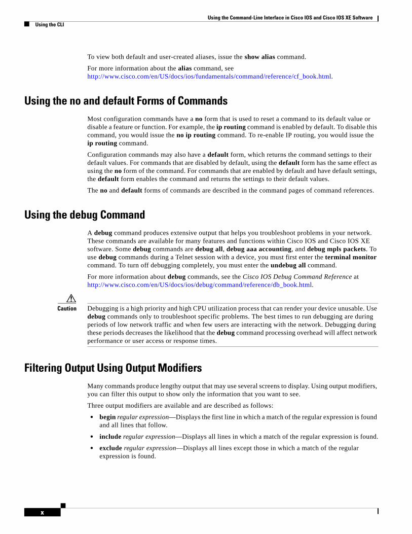
To view both default and user-created aliases, issue the show alias command.
For more information about the alias command, see http://www.cisco.com/en/US/docs/ios/fundamentals/command/reference/cf_book.html.
Using the no and default Forms of CommandsMost configuration commands have a no form that is used to reset a command to its default value or disable a feature or function. For example, the ip routing command is enabled by default. To disable this command, you would issue the no ip routing command. To re-enable IP routing, you would issue the ip routing command.
Configuration commands may also have a default form, which returns the command settings to their default values. For commands that are disabled by default, using the default form has the same effect as using the no form of the command. For commands that are enabled by default and have default settings, the default form enables the command and returns the settings to their default values.
The no and default forms of commands are described in the command pages of command references.
Using the debug CommandA debug command produces extensive output that helps you troubleshoot problems in your network. These commands are available for many features and functions within Cisco IOS and Cisco IOS XE software. Some debug commands are debug all, debug aaa accounting, and debug mpls packets. To use debug commands during a Telnet session with a device, you must first enter the terminal monitor command. To turn off debugging completely, you must enter the undebug all command.
For more information about debug commands, see the Cisco IOS Debug Command Reference at http://www.cisco.com/en/US/docs/ios/debug/command/reference/db_book.html.
Caution Debugging is a high priority and high CPU utilization process that can render your device unusable. Use debug commands only to troubleshoot specific problems. The best times to run debugging are during periods of low network traffic and when few users are interacting with the network. Debugging during these periods decreases the likelihood that the debug command processing overhead will affect network performance or user access or response times.
Filtering Output Using Output ModifiersMany commands produce lengthy output that may use several screens to display. Using output modifiers, you can filter this output to show only the information that you want to see.
Three output modifiers are available and are described as follows:
• begin regular expression—Displays the first line in which a match of the regular expression is found and all lines that follow.
• include regular expression—Displays all lines in which a match of the regular expression is found.
• exclude regular expression—Displays all lines except those in which a match of the regular expression is found.
Using the Command-Line Interface in Cisco IOS and Cisco IOS XE SoftwareUsing the CLI
xi
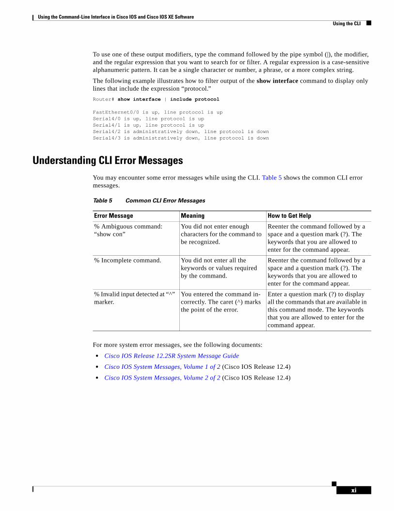
To use one of these output modifiers, type the command followed by the pipe symbol (|), the modifier, and the regular expression that you want to search for or filter. A regular expression is a case-sensitive alphanumeric pattern. It can be a single character or number, a phrase, or a more complex string.
The following example illustrates how to filter output of the show interface command to display only lines that include the expression “protocol.”
Router# show interface | include protocol
FastEthernet0/0 is up, line protocol is upSerial4/0 is up, line protocol is upSerial4/1 is up, line protocol is upSerial4/2 is administratively down, line protocol is downSerial4/3 is administratively down, line protocol is down
Understanding CLI Error MessagesYou may encounter some error messages while using the CLI. Table 5 shows the common CLI error messages.
For more system error messages, see the following documents:
• Cisco IOS Release 12.2SR System Message Guide
• Cisco IOS System Messages, Volume 1 of 2 (Cisco IOS Release 12.4)
• Cisco IOS System Messages, Volume 2 of 2 (Cisco IOS Release 12.4)
Table 5 Common CLI Error Messages
Error Message Meaning How to Get Help
% Ambiguous command: “show con”
You did not enter enough characters for the command to be recognized.
Reenter the command followed by a space and a question mark (?). The keywords that you are allowed to enter for the command appear.
% Incomplete command. You did not enter all the keywords or values required by the command.
Reenter the command followed by a space and a question mark (?). The keywords that you are allowed to enter for the command appear.
% Invalid input detected at “^” marker.
You entered the command in-correctly. The caret (^) marks the point of the error.
Enter a question mark (?) to display all the commands that are available in this command mode. The keywords that you are allowed to enter for the command appear.

Using the Command-Line Interface in Cisco IOS and Cisco IOS XE SoftwareSaving Changes to a Configuration
xii
Saving Changes to a ConfigurationTo save changes that you made to the configuration of a device, you must issue the copy running-config startup-config command or the copy system:running-config nvram:startup-config command. When you issue these commands, the configuration changes that you made are saved to the startup configuration and saved when the software reloads or power to the device is turned off or interrupted. The following example shows the syntax of the copy running-config startup-config command:
Router# copy running-config startup-configDestination filename [startup-config]?
You press Enter to accept the startup-config filename (the default), or type a new filename and then press Enter to accept that name. The following output is displayed indicating that the configuration was saved:
Building configuration...[OK]Router#
On most platforms, the configuration is saved to NVRAM. On platforms with a Class A flash file system, the configuration is saved to the location specified by the CONFIG_FILE environment variable. The CONFIG_FILE variable defaults to NVRAM.
Additional Information • “Using the Cisco IOS Command-Line Interface” section of the
Cisco IOS Configuration Fundamentals Configuration Guide:
http://www.cisco.com/en/US/docs/ios/fundamentals/configuration/guide/cf_cli-basics.html
or
“Using Cisco IOS XE Software” chapter of the Cisco ASR1000 Series Aggregation Services Routers Software Configuration Guide:
http://www.cisco.com/en/US/docs/routers/asr1000/configuration/guide/chassis/using_cli.html
• Cisco Product Support Resources
http://www.cisco.com/web/psa/products/index.html
• Support area on Cisco.com (also search for documentation by task or product)
http://www.cisco.com/en/US/support/index.html
• White Paper: Cisco IOS Reference Guide
http://www.cisco.com/en/US/products/sw/iosswrel/ps1828/products_white_paper09186a008018305e.shtml
• Software Download Center (downloads; tools; licensing, registration, advisory, and general information) (requires Cisco.com User ID and password)
http://www.cisco.com/kobayashi/sw-center/
• Error Message Decoder, a tool to help you research and resolve error messages for Cisco IOS software
http://www.cisco.com/pcgi-bin/Support/Errordecoder/index.cgi

Using the Command-Line Interface in Cisco IOS and Cisco IOS XE SoftwareAdditional Information
xiii
• Command Lookup Tool, a tool to help you find detailed descriptions of Cisco IOS commands (requires Cisco.com user ID and password)
http://tools.cisco.com/Support/CLILookup
• Output Interpreter, a troubleshooting tool that analyzes command output of supported show commands
https://www.cisco.com/pcgi-bin/Support/OutputInterpreter/home.pl\
CCDE, CCENT, Cisco Eos, Cisco Lumin, Cisco Nexus, Cisco StadiumVision, Cisco TelePresence, the Cisco logo, DCE, and Welcome to the Human Network are trademarks; Changing the Way We Work, Live, Play, and Learn and Cisco Store are service marks; and Access Registrar, Aironet, AsyncOS, Bringing the Meeting To You, Catalyst, CCDA, CCDP, CCIE, CCIP, CCNA, CCNP, CCSP, CCVP, Cisco, the Cisco Certified Internetwork Expert logo, Cisco IOS, Cisco Press, Cisco Systems, Cisco Systems Capital, the Cisco Systems logo, Cisco Unity, Collaboration Without Limitation, EtherFast, EtherSwitch, Event Center, Fast Step, Follow Me Browsing, FormShare, GigaDrive, HomeLink, Internet Quotient, IOS, iPhone, iQ Expertise, the iQ logo, iQ Net Readiness Scorecard, iQuick Study, IronPort, the IronPort logo, LightStream, Linksys, MediaTone, MeetingPlace, MeetingPlace Chime Sound, MGX, Networkers, Networking Academy, Network Registrar, PCNow, PIX, PowerPanels, ProConnect, ScriptShare, SenderBase, SMARTnet, Spectrum Expert, StackWise, The Fastest Way to Increase Your Internet Quotient, TransPath, WebEx, and the WebEx logo are registered trademarks of Cisco Systems, Inc. and/or its affiliates in the United States and certain other countries.
All other trademarks mentioned in this document or Website are the property of their respective owners. The use of the word partner does not imply a partnership relationship between Cisco and any other company. (0807R) Any Internet Protocol (IP) addresses used in this document are not intended to be actual addresses. Any examples, command display output, and figures included in the document are shown for illustrative purposes only. Any use of actual IP addresses in illustrative content is unintentional and coincidental. © 2007–2008 Cisco Systems, Inc. All rights reserved.

Using the Command-Line Interface in Cisco IOS and Cisco IOS XE SoftwareAdditional Information
xiv
Americas Headquarters:Cisco Systems, Inc., 170 West Tasman Drive, San Jose, CA 95134-1706 USA
© 2008 Cisco Systems, Inc. All rights reserved.
Cisco IOS Voice Port Feature Roadmap
This roadmap provides information about Cisco IOS voice features involving voice port configuration. It contains the following:
• Platforms and Cisco IOS Software Images, page 7
• Cisco IOS Voice Port Feature List, page 7
Note This chapter describes how to access Cisco Feature Navigator. It also lists and describes, by Cisco IOS release, voice port features for that release.
For information about the full set of Cisco IOS voice features, see the entire Cisco IOS Voice Configuration Library—including library preface, glossary, and other documents—at http://www.cisco.com/en/US/docs/ios/12_3/vvf_c/cisco_ios_voice_configuration_library_glossary/vcl.html.
Platforms and Cisco IOS Software ImagesUse Cisco Feature Navigator to find information about platform support and Cisco IOS and Catalyst OS software image support. To access Cisco Feature Navigator, go to http://www.cisco.com/go/cfn. An account on Cisco.com is not required.
Cisco IOS Voice Port Feature ListTable 1 lists voice port features by Cisco IOS release. Features that are introduced in a particular release are available in that and subsequent releases.

Cisco IOS Voice Port Feature Roadmap Cisco IOS Voice Port Feature List
8Cisco IOS Voice Port Configuration Guide
Table 1 Voice Port Features by Cisco IOS Release
Release Feature Name Feature Description Where Documented
12.4(20)T Software-Configurable 128-ms Echo Cancellation
Beginning in Release 12.4(20)T, software-configurable echo cancellation coverage was expanded to include 80, 96, 112, and 128 milliseconds. The default is changed from 64 ms to 128 ms.
Configuring Echo Cancellation and Configuring Hardware Echo Cancellation on T1/E1 Multiflex Voice/WAN Interface Cards and NextPort-Based Voice Tuning and Echo Cancellation
12.4(15)XZ Enhancements to the Cisco 880 Series Routers
Beginning in Release 12.4(15)XZ, the Cisco 880 broadband series routers integrate access technologies such as the VDSL2, 3G; adds voice for service provider-managed services and for enterprise teleworkers. In addition, the broadband series routers offer UTM features such as URL filtering and optional IEEE 802.11n integrated access points that can be managed using LWAPP.
Configuring Analog Voice Ports and Configuring Digital Voice Ports
12.3(14)T Hardware Echo Cancellation Two echo cancellation modules (EC-MFT-32 and EC-MFT-64) provide hardware echo cancellation with a hard-coded tail length of 128 milliseconds for VWIC2s.
Configuring Hardware Echo Cancellation on T1/E1 Multiflex Voice/WAN Interface Cards
12.3(11)T NextPort-Based Voice-Tuning and Dual-Filter G.168 Echo Canceller
NextPort dual-filter G.168 echo canceller (EC) improves voice quality in VoIP connections by providing relatively less residual echo leakage, better nonlinear processing (NLP) timing, less clipping, and better comfort noise generation (CNG) in most environments.
NextPort-Based Voice Tuning and Echo Cancellation

Cisco IOS Voice Port Feature Roadmap Cisco IOS Voice Port Feature List
9Cisco IOS Voice Port Configuration Guide
CCDE, CCENT, Cisco Eos, Cisco Lumin, Cisco Nexus, Cisco StadiumVision, Cisco TelePresence, the Cisco logo, DCE, and Welcome to the Human Network are trademarks; Changing the Way We Work, Live, Play, and Learn and Cisco Store are service marks; and Access Registrar, Aironet, AsyncOS, Bringing the Meeting To You, Catalyst, CCDA, CCDP, CCIE, CCIP, CCNA, CCNP, CCSP, CCVP, Cisco, the Cisco Certified Internetwork Expert logo, Cisco IOS, Cisco Press, Cisco Systems, Cisco Systems Capital, the Cisco Systems logo, Cisco Unity, Collaboration Without Limitation, EtherFast, EtherSwitch, Event Center, Fast Step, Follow Me Browsing, FormShare, GigaDrive, HomeLink, Internet Quotient, IOS, iPhone, iQ Expertise, the iQ logo, iQ Net Readiness Scorecard, iQuick Study, IronPort, the IronPort logo, LightStream, Linksys, MediaTone, MeetingPlace, MeetingPlace Chime Sound, MGX, Networkers, Networking Academy, Network Registrar, PCNow, PIX, PowerPanels, ProConnect, ScriptShare, SenderBase, SMARTnet, Spectrum Expert, StackWise, The Fastest Way to Increase Your Internet Quotient, TransPath, WebEx, and the WebEx logo are registered trademarks of Cisco Systems, Inc. and/or its affiliates in the United States and certain other countries.
All other trademarks mentioned in this document or Website are the property of their respective owners. The use of the word partner does not imply a partnership relationship between Cisco and any other company. (0807R)
Any Internet Protocol (IP) addresses used in this document are not intended to be actual addresses. Any examples, command display output, and figures included in the document are shown for illustrative purposes only. Any use of actual IP addresses in illustrative content is unintentional and coincidental.
© 2008 Cisco Systems, Inc. All rights reserved.
12.3(7)T IP Communications High-Density Digital Voice/Fax Network Module
This feature supports high-density digital voice and low-density analog voice connectivity along with data and integrated access connectivity. The network modules offer built-in T1/E1 ports, and include a single VIC/voice WAN interface card (VWIC) slot for FXS, FXO, E&M, software-configured CAMA, DID, BRI, or E1 and T1 cards, up to a maximum of four T1/E1 ports. The network modules also support up to 32 HDLC channels with an aggregate capacity of 2.048 Mbps.
Configuring Digital Voice Ports
12.2(13)T Enhanced ITU-T G.168 Echo Cancellation
This feature offers improved standards for echo cancellation performance. Configurable tail length is increased, up to 64 ms. Minimum ERL is configurable to greater than or equal to 0 dB, 3 dB, or 6 dB. Echo suppression is no longer needed because of faster convergence.
Configuring Echo Cancellation
Table 1 Voice Port Features by Cisco IOS Release (continued)
Release Feature Name Feature Description Where Documented

Cisco IOS Voice Port Feature Roadmap Cisco IOS Voice Port Feature List
10Cisco IOS Voice Port Configuration Guide

Americas Headquarters:Cisco Systems, Inc., 170 West Tasman Drive, San Jose, CA 95134-1706 USA
Voice Port Configuration Overview
Voice ports are found at the intersections of packet-based networks and traditional telephony networks, and they facilitate the passing of voice and call signals between the two networks. Physically, voice ports connect a router or access server to a line from a circuit-switched telephony device in a PBX or the PSTN.
Basic software configuration for voice ports describes the type of connection being made and the type of signaling to take place over this connection. In addition to the commands for basic configuration, there are also commands that provide fine-tuning for voice quality, enable special features, and specify parameters to match those of proprietary PBXs.
This document includes the following chapters:
• Configuring Analog Voice Ports
• Configuring Digital Voice Ports
• Fine-Tuning Analog and Digital Voice Ports
• Configuring Echo Cancellation
• Configuring Hardware Echo Cancellation on T1/E1 Multiflex Voice/WAN Interface Cards
• NextPort-Based Voice Tuning and Echo Cancellation
• Verifying Analog and Digital Voice-Port Configurations
• Troubleshooting Analog and Digital Voice Port Configurations
Not all voice-port commands are covered in this document. Some are described in the Cisco IOS ISDN Voice Configuration Guide, Release 12.4 or the Trunk Management Features document, Cisco IOS Voice Configuration Library, Release 12.4. The voice-port configuration commands included in this document are fully documented in the Cisco IOS Voice Command Reference.
Finding Support Information for Platforms and Cisco IOS Software Images
Use Cisco Feature Navigator to find information about platform support and Cisco IOS and Catalyst OS software image support. To access Cisco Feature Navigator, go to http://www.cisco.com/go/cfn. An account on Cisco.com is not required.
Voice Port Configuration Overview Voice Port Configuration Overview
2Cisco IOS Voice Port Configuration Guide
Voice Port Configuration OverviewVoice ports on routers and access servers emulate physical telephony switch connections so that voice calls and their associated signaling can be transferred intact between a packet network and a circuit-switched network or device. For a voice call to occur, certain information must be passed between the telephony devices at either end of the call, such as the devices’ on-hook status, the line’s availability, and whether an incoming call is trying to reach a device. This information is referred to as signaling, and to process it properly, the devices at both ends of the call segment (that is, those directly connected to each other) must use the same type of signaling.
The devices in the packet network must be configured to convey signaling information in a way that the circuit-switched network can understand. They must also be able to understand signaling information received from the circuit-switched network. This is accomplished by installing appropriate voice hardware in the router or access server and by configuring the voice ports that connect to telephony devices or the circuit-switched network.
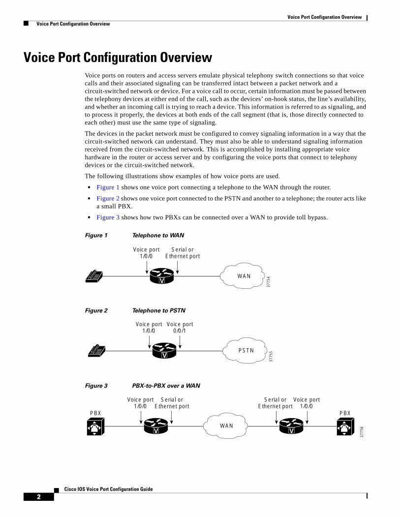
The following illustrations show examples of how voice ports are used.
• Figure 1 shows one voice port connecting a telephone to the WAN through the router.
• Figure 2 shows one voice port connected to the PSTN and another to a telephone; the router acts like a small PBX.
• Figure 3 shows how two PBXs can be connected over a WAN to provide toll bypass.
Figure 1 Telephone to WAN
Figure 2 Telephone to PSTN
Figure 3 PBX-to-PBX over a WAN
V
Voice port1/0/0
Serial orEthernet port
WAN
3775
4
V
Voice port1/0/0
Voice port0/0/1
PSTN
3775
5
V
Voice port1/0/0
PBX PBX
Serial orEthernet port
Serial orEthernet port
V
Voice port1/0/0
WAN
3775
6

Voice Port Configuration Overview Voice Port Configuration Overview
3Cisco IOS Voice Port Configuration Guide
Cisco provides a variety of Cisco IOS commands for flexibility in configuring voice ports to match the physical attributes of the voice connections that are being made. Some of these connections are made using analog means of transmission, while others use digital transmission. Table 1 shows the analog and digital voice-port connection support of the router platforms discussed in this document.
Telephony Signaling InterfacesVoice ports on routers and access servers physically connect the router or access server to telephony devices such as telephones, fax machines, PBXs, and PSTN central office (CO) switches. These devices may use any of several types of signaling interfaces to generate information about on-hook status, ringing, and line seizure.
The router’s voice-port hardware and software need to be configured to transmit and receive the same type of signaling being used by the device with which they are interfacing so that calls can be exchanged smoothly between the packet network and the circuit-switched network.
The signaling interfaces discussed in this document include foreign exchange office (FXO), foreign exchange station (FXS), and receive and transmit (E&M), which are types of analog interfaces. Some digital connections emulate FXO, FXS, and E&M interfaces, and they are discussed in the “FXS and FXO Interfaces” section on page 4 and the “E&M Interfaces” section on page 5. It is important to know which signaling method the telephony side of the connection is using, and to match the router configuration and voice interface hardware to that signaling method.
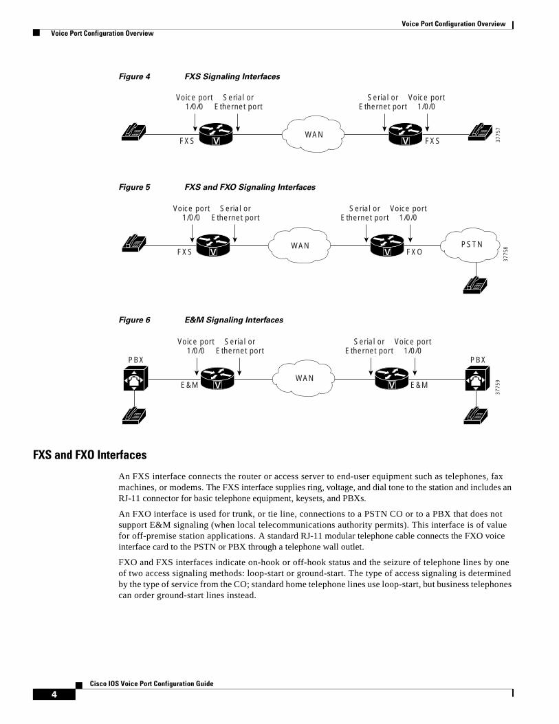
The next three illustrations show how the different signaling interfaces are associated with different uses of voice ports. In Figure 4, FXS signaling is used for end-user telephony equipment, such as a telephone or fax machine. Figure 5 shows an FXS connection to a telephone and an FXO connection to the PSTN at the far side of a WAN; this might be a telephone at a local office going over a WAN to a router at headquarters that connects to the PSTN. In Figure 6, two PBXs are connected across a WAN by E&M interfaces. This illustrates the path over a WAN between two geographically separated offices in the same company.
Table 1 Analog and Digital Voice-Port Support on Cisco Platforms
Platform Analog Digital
Cisco 880 series (includes IAD881B, IAD881F, C881SRST, IAD888B, IAD888F, and C888SRST)
Yes Yes
Cisco 1750 Yes No
Cisco 2600 series Yes Yes
Cisco 3600 series Yes Yes
Cisco 3700 series Yea Yes
Cisco 7200 series No Yes
Cisco 7500 series No Yes
Cisco AS5300 No Yes
Cisco AS5350 No Yes
Cisco AS5400 No Yes
Cisco AS5800 No Yes
Cisco AS5850 No Yes
Cisco MC3810 Yes Yes
Voice Port Configuration Overview Voice Port Configuration Overview
4Cisco IOS Voice Port Configuration Guide
Figure 4 FXS Signaling Interfaces
Figure 5 FXS and FXO Signaling Interfaces
Figure 6 E&M Signaling Interfaces
FXS and FXO Interfaces
An FXS interface connects the router or access server to end-user equipment such as telephones, fax machines, or modems. The FXS interface supplies ring, voltage, and dial tone to the station and includes an RJ-11 connector for basic telephone equipment, keysets, and PBXs.
An FXO interface is used for trunk, or tie line, connections to a PSTN CO or to a PBX that does not support E&M signaling (when local telecommunications authority permits). This interface is of value for off-premise station applications. A standard RJ-11 modular telephone cable connects the FXO voice interface card to the PSTN or PBX through a telephone wall outlet.
FXO and FXS interfaces indicate on-hook or off-hook status and the seizure of telephone lines by one of two access signaling methods: loop-start or ground-start. The type of access signaling is determined by the type of service from the CO; standard home telephone lines use loop-start, but business telephones can order ground-start lines instead.
V
Voice port1/0/0
FXS FXS 3775
7
Serial orEthernet port
Serial orEthernet port
V
Voice port1/0/0
WAN
V
Voice port1/0/0
FXS FXO
3775
8
Serial orEthernet port
Serial orEthernet port
V
Voice port1/0/0
WAN PSTN
V
Voice port1/0/0
PBX PBX
E&M E&M
3775
9
Serial orEthernet port
Serial orEthernet port
V
Voice port1/0/0
WAN
Voice Port Configuration Overview Voice Port Configuration Overview
5Cisco IOS Voice Port Configuration Guide
Loop-start is the more common of the access signaling techniques. When a handset is picked up (the telephone goes off-hook), this action closes the circuit that draws current from the telephone company CO and indicates a change in status, which signals the CO to provide dial tone. An incoming call is signaled from the CO to the handset by sending a signal in a standard on/off pattern, which causes the telephone to ring.
Loop-start has two disadvantages, however, that usually are not a problem on residential telephones but that become significant with the higher call volume experienced on business telephones. Loop-start signaling has no means of preventing two sides from seizing the same line simultaneously, a condition known as glare. Also, loop-start signaling does not provide switch-side disconnect supervision for FXO calls. The telephony switch (the connection in the PSTN, another PBX, or key system) expects the router’s FXO interface, which looks like a telephone to the switch, to hang up the calls it receives through its FXO port. However, this function is not built into the router for received calls; it operates only for calls originating from the FXO port.
Another access signaling method used by FXO and FXS interfaces to indicate on-hook or off-hook status to the CO is ground-start signaling. It works by using ground and current detectors that allow the network to indicate off-hook or seizure of an incoming call independent of the ringing signal and allow for positive recognition of connects and disconnects. For this reason, ground-start signaling is typically used on trunk lines between PBXs and in businesses where call volume on loop-start lines can result in glare. See the “Configuring Disconnect Supervision” and “Configuring FXO Supervisory Disconnect Tones” sections in the “Fine-Tuning Analog and Digital Voice Ports” chapter for voice port commands that configure additional recognition of disconnect signaling.
In most cases, the default voice port command values are sufficient to configure FXO and FXS voice ports.
E&M Interfaces
Trunk circuits connect telephone switches to one another; they do not connect end-user equipment to the network. The most common form of analog trunk circuit is the E&M interface, which uses special signaling paths that are separate from the trunk’s audio path to convey information about the calls. The signaling paths are known as the E-lead and the M-lead. The name E&M is thought to derive from the phrase Ear and Mouth or rEceive and transMit although it could also come from Earth and Magnet. The history of these names dates back to the days of telegraphy, when the CO side had a key that grounded the E circuit, and the other side had a sounder with an electromagnet attached to a battery. Descriptions such as Ear and Mouth were adopted to help field personnel determine the direction of a signal in a wire. E&M connections from routers to telephone switches or to PBXs are preferable to FXS/FXO connections because E&M provides better answer and disconnect supervision.
Like a serial port, an E&M interface has a data terminal equipment/data communications equipment (DTE/DCE) type of reference. In telecommunications, the trunking side is similar to the DCE, and is usually associated with CO functionality. The router acts as this side of the interface. The other side is referred to as the signaling side, like a DTE, and is usually a device such as a PBX. Five distinct physical configurations for the signaling part of the interface (Types I-V) use different methods to signal on-hook/off-hook status, as shown in Table 2. Cisco voice implementation supports E&M Types I, II, III, and V.
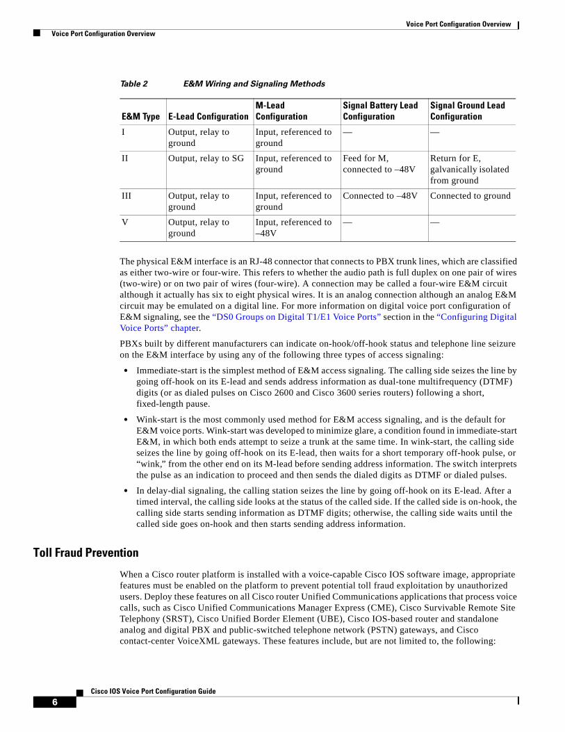
Voice Port Configuration Overview Voice Port Configuration Overview
6Cisco IOS Voice Port Configuration Guide
The physical E&M interface is an RJ-48 connector that connects to PBX trunk lines, which are classified as either two-wire or four-wire. This refers to whether the audio path is full duplex on one pair of wires (two-wire) or on two pair of wires (four-wire). A connection may be called a four-wire E&M circuit although it actually has six to eight physical wires. It is an analog connection although an analog E&M circuit may be emulated on a digital line. For more information on digital voice port configuration of E&M signaling, see the “DS0 Groups on Digital T1/E1 Voice Ports” section in the “Configuring Digital Voice Ports” chapter.
PBXs built by different manufacturers can indicate on-hook/off-hook status and telephone line seizure on the E&M interface by using any of the following three types of access signaling:
• Immediate-start is the simplest method of E&M access signaling. The calling side seizes the line by going off-hook on its E-lead and sends address information as dual-tone multifrequency (DTMF) digits (or as dialed pulses on Cisco 2600 and Cisco 3600 series routers) following a short, fixed-length pause.
• Wink-start is the most commonly used method for E&M access signaling, and is the default for E&M voice ports. Wink-start was developed to minimize glare, a condition found in immediate-start E&M, in which both ends attempt to seize a trunk at the same time. In wink-start, the calling side seizes the line by going off-hook on its E-lead, then waits for a short temporary off-hook pulse, or “wink,” from the other end on its M-lead before sending address information. The switch interprets the pulse as an indication to proceed and then sends the dialed digits as DTMF or dialed pulses.
• In delay-dial signaling, the calling station seizes the line by going off-hook on its E-lead. After a timed interval, the calling side looks at the status of the called side. If the called side is on-hook, the calling side starts sending information as DTMF digits; otherwise, the calling side waits until the called side goes on-hook and then starts sending address information.
Toll Fraud Prevention
When a Cisco router platform is installed with a voice-capable Cisco IOS software image, appropriate features must be enabled on the platform to prevent potential toll fraud exploitation by unauthorized users. Deploy these features on all Cisco router Unified Communications applications that process voice calls, such as Cisco Unified Communications Manager Express (CME), Cisco Survivable Remote Site Telephony (SRST), Cisco Unified Border Element (UBE), Cisco IOS-based router and standalone analog and digital PBX and public-switched telephone network (PSTN) gateways, and Cisco contact-center VoiceXML gateways. These features include, but are not limited to, the following:
Table 2 E&M Wiring and Signaling Methods
E&M Type E-Lead ConfigurationM-Lead Configuration
Signal Battery Lead Configuration
Signal Ground Lead Configuration
I Output, relay to ground
Input, referenced to ground
— —
II Output, relay to SG Input, referenced to ground
Feed for M, connected to –48V
Return for E, galvanically isolated from ground
III Output, relay to ground
Input, referenced to ground
Connected to –48V Connected to ground
V Output, relay to ground
Input, referenced to –48V
— —

Voice Port Configuration Overview Voice Port Configuration Overview
7Cisco IOS Voice Port Configuration Guide
• Disable secondary dial tone on voice ports—By default, secondary dial tone is presented on voice ports on Cisco router gateways. Use private line automatic ringdown (PLAR) for foreign exchange office (FXO) ports and direct-inward-dial (DID) for T1/E1 ports to prevent secondary dial tone from being presented to inbound callers.
• Cisco router access control lists (ACLs)—Define ACLs to allow only explicitly valid sources of calls to the router or gateway, and therefore to prevent unauthorized Session Initiation Protocol (SIP) or H.323 calls from unknown parties to be processed and connected by the router or gateway.
• Close unused SIP and H.323 ports—If either the SIP or H.323 protocol is not used in your deployment, close the associated protocol ports. If a Cisco voice gateway has dial peers configured to route calls outbound to the PSTN using either time division multiplex (TDM) trunks or IP, close the unused H.323 or SIP ports so that calls from unauthorized endpoints cannot connect calls. If the protocols are used and the ports must remain open, use ACLs to limit access to legitimate sources.
• Change SIP port 5060—If SIP is actively used, consider changing the port to something other than well-known port 5060.
• SIP registration—If SIP registration is available on SIP trunks, turn on this feature because it provides an extra level of authentication and validation that only legitimate sources can connect calls. If it is not available, ensure that the appropriate ACLs are in place.
• SIP Digest Authentication—If the SIP Digest Authentication feature is available for either registrations or invites, turn this feature on because it provides an extra level of authentication and validation that only legitimate sources can connect calls.
• Explicit incoming and outgoing dial peers—Use explicit dial peers to control the types and parameters of calls allowed by the router, especially in IP-to-IP connections used on CME, SRST, and Cisco UBE. Incoming dial peers offer additional control on the sources of calls, and outgoing dial peers on the destinations. Incoming dial peers are always used for calls. If a dial peer is not explicitly defined, the implicit dial peer 0 is used to allow all calls.
• Explicit destination patterns—Use dial peers with more granularity than .T for destination patterns to block disallowed off-net call destinations. Use class of restriction (COR) on dial peers with specific destination patterns to allow even more granular control of calls to different destinations on the PSTN.
• Translation rules—Use translation rules to manipulate dialed digits before calls connect to the PSTN to provide better control over who may dial PSTN destinations. Legitimate users dial an access code and an augmented number for PSTN for certain PSTN (for example, international) locations.
• Tcl and VoiceXML scripts—Attach a Tcl/VoiceXML script to dial peers to do database lookups or additional off-router authorization checks to allow or deny call flows based on origination or destination numbers. Tcl/VoiceXML scripts can also be used to add a prefix to inbound DID calls. If the prefix plus DID matches internal extensions, then the call is completed. Otherwise, a prompt can be played to the caller that an invalid number has been dialed.
• Host name validation—Use the “permit hostname” feature to validate initial SIP Invites that contain a fully qualified domain name (FQDN) host name in the Request Uniform Resource Identifier (Request URI) against a configured list of legitimate source hostnames.
• Dynamic Domain Name Service (DNS)—If you are using DNS as the “session target” on dial peers, the actual IP address destination of call connections can vary from one call to the next. Use voice source groups and ACLs to restrict the valid address ranges expected in DNS responses (which are used subsequently for call setup destinations).
For more configuration guidance, see the “Cisco IOS Unified Communications Toll Fraud Prevention” paper.

Voice Port Configuration Overview Voice Port Configuration Overview
8Cisco IOS Voice Port Configuration Guide
CCDE, CCENT, CCSI, Cisco Eos, Cisco HealthPresence, Cisco IronPort, the Cisco logo, Cisco Lumin, Cisco Nexus, Cisco Nurse Connect, Cisco StackPower, Cisco StadiumVision, Cisco TelePresence, Cisco Unified Computing System, Cisco WebEx, DCE, Flip Channels, Flip for Good, Flip Mino, Flip Video, Flip Video (Design), Flipshare (Design), Flip Ultra, and Welcome to the Human Network are trademarks; Changing the Way We Work, Live, Play, and Learn, Cisco Store, and Flip Gift Card are service marks; and Access Registrar, Aironet, AsyncOS, Bringing the Meeting To You, Catalyst, CCDA, CCDP, CCIE, CCIP, CCNA, CCNP, CCSP, CCVP, Cisco, the Cisco Certified Internetwork Expert logo, Cisco IOS, Cisco Press, Cisco Systems, Cisco Systems Capital, the Cisco Systems logo, Cisco Unity, Collaboration Without Limitation, EtherFast, EtherSwitch, Event Center, Fast Step, Follow Me Browsing, FormShare, GigaDrive, HomeLink, Internet Quotient, IOS, iPhone, iQuick Study, IronPort, the IronPort logo, LightStream, Linksys, MediaTone, MeetingPlace, MeetingPlace Chime Sound, MGX, Networkers, Networking Academy, Network Registrar, PCNow, PIX, PowerPanels, ProConnect, ScriptShare, SenderBase, SMARTnet, Spectrum Expert, StackWise, The Fastest Way to Increase Your Internet Quotient, TransPath, WebEx, and the WebEx logo are registered trademarks of Cisco Systems, Inc. and/or its affiliates in the United States and certain other countries.
All other trademarks mentioned in this document or website are the property of their respective owners. The use of the word partner does not imply a partnership relationship between Cisco and any other company. (0907R)
Any Internet Protocol (IP) addresses used in this document are not intended to be actual addresses. Any examples, command display output, and figures included in the document are shown for illustrative purposes only. Any use of actual IP addresses in illustrative content is unintentional and coincidental. © 2009 Cisco Systems, Inc. All rights reserved.
Americas Headquarters:Cisco Systems, Inc., 170 West Tasman Drive, San Jose, CA 95134-1706 USA
© 2008 Cisco Systems, Inc. All rights reserved.
Configuring Analog Voice Ports
Analog voice port interfaces connect routers in packet-based networks to analog two-wire or four-wire analog circuits in telephony networks. Two-wire circuits connect to analog telephone or fax devices, and four-wire circuits connect to PBXs. Connections to the PSTN central office (CO) are typically made with digital interfaces.
This chapter describes how to configure analog voice ports and covers the following topics:
• Prerequisites for Configuring Analog Voice Ports, page 19
• Information About Analog Voice Hardware, page 20
• Configuring Basic Parameters on Analog FXO, FXS, or E&M Voice Ports, page 22
• Configuring Codec Complexity for Analog Voice Ports on the Cisco MC3810 with High-Performance Compression Modules, page 26
Three other sections in this document provide help with fine-tuning and troubleshooting:
• Fine-Tuning Analog and Digital Voice Ports, page 51
• Verifying Analog and Digital Voice-Port Configurations, page 125
• Troubleshooting Analog and Digital Voice Port Configurations, page 137
Prerequisites for Configuring Analog Voice Ports• Obtain two- or four-wire line service from your service provider or from a PBX.
• Complete your company’s dial plan.
• Establish a working telephony network based on your company’s dial plan.
• Install at least one other network module or WAN interface card to provide the connection to the network LAN or WAN.
• Establish a working IP and Frame Relay or ATM network. For more information about configuring IP, refer to the Cisco IOS IP Configuration Guide, Release 12.4.
• Install appropriate voice processing and voice interface hardware on the router. See the “Information About Analog Voice Hardware” section on page 20.
• Gather the following information about the telephony connection of the voice port:

Configuring Analog Voice Ports Information About Analog Voice Hardware
20Cisco IOS Voice Port Configuration Guide
– Telephony signaling interface: FXO, FXS, or E&M
– Locale code (usually the country) for call progress tones
– If FXO, type of dialing: DTMF (touch-tone) or pulse
– If FXO, type of start signal: loop-start or ground-start
– If E&M, type: I, II, III, or V
– If E&M, type of line: two-wire or four-wire
– If E&M, type of start signal: wink, immediate, delay-dial
If you are connecting a voice-port interface to a PBX, it is important to understand the PBX’s wiring scheme and timing parameters. This information should be available from your PBX vendor or the reference manuals that accompany your PBX.
Note The slot and port numbering of interface cards differs for each of the voice-enabled routers. For the specific slot and port designations for your hardware platform, refer to the Cisco Interface Cards Hardware Installation Guide. More current information may be available in the release notes for the Cisco IOS software you are using.
Information About Analog Voice HardwareThis section describes the general types of analog voice port hardware available for the following router platforms:
• Cisco 880 Series Routers, page 20
• Cisco 1750 Modular Router, page 21
• Cisco 2600 Series, Cisco 3600 Series, and Cisco 3700 Series Routers, page 21
• Cisco MC3810, page 22
Note For current information about supported hardware, refer to the release notes for the platform and Cisco IOS release being used.
Cisco 880 Series RoutersBeginning with Cisco IOS Release 12.4(15)XZ, the Cisco 880 series fixed router platforms support the implementation of analog (FXS/DID/FXO) and digital (BRI S/T) voice ports. The IAD881B, IAD881F, IAD888B, and IAD888F models support voice interface FXS or BRI. The IAD881F and IAD888F models have four FXS ports and the IAD881B and IAD888B models support two ports for ISDN BRI digital voice interface.
In the IAD881B and IAD888B models, the voice BRI interface presents an ISDN S/T interface to connect either to an NT1 terminating an ISDN telephone network (TE-side) or to a TE user device such as an ISDN telephone or PBX (NT-side). In the IAD881B and IAD888B models, the BRI interface is available as the primary voice interface and is intended to be connected to a PBX (network side trunk). All the voice interfaces are onboard though they are recognized as a 4-port FXS VIC and a 2-port BRI VIC in order to leverage existing voice drivers.
Configuring Analog Voice Ports Information About Analog Voice Hardware
21Cisco IOS Voice Port Configuration Guide
Note If the primary voice interface is FXS and the backup is BRI, then ports 0, 1, 2, and 3 are analog voice ports, and ports 4 and 5 are digital. If the primary voice interface is BRI, then ports 1, 2, 3, and 4 are digital.
The C881 and C888 SRST models automatically detect a failure occuring in the network and initiate a process to auto-configure the router. This process provides call-processing backup redundancy for the IP and FXS phones and helps to ensure that telephony capabilities stay operational. All the IP or analog phones hanging off of a telecommuter site are controlled by the headquarters office call control (Cisco Unified CallManager or CallManager Express). In case of a WAN failure, the telecommuter router allows all phones to re-register to it in SRST mode and allow all inbound and outbound dialing to be routed off to the PSTN (using back up FXO or BRI port). Upon restoration of WAN connectivity, the system automatically shifts call processing back to the primary Cisco Unified Call Manager cluster.
Cisco 1750 Modular RouterThe Cisco 1750 modular router provides VoIP functionality and can carry voice traffic (for example, telephone calls and faxes) over an IP network. To make a voice connection, the router must have a supported voice interface card (VIC) installed. The Cisco 1750 router supports two slots for either WAN interface cards (WICs) or VICs and supports one VIC-only slot. For analog connections, two-port VICs are available to support FXO, FXS, and E&M signaling. VICs provide direct connections to telephone equipment (analog phones, analog fax machines, key systems, or PBXs) or to a PSTN.
Cisco 2600 Series, Cisco 3600 Series, and Cisco 3700 Series RoutersThe Cisco 2600 series, Cisco 3600 series, and Cisco 3700 series routers are modular, multifunction platforms that combine dial access, routing, LAN-to-LAN services, and multiservice integration of voice, video, and data in the same device.
Voice network modules installed in Cisco 2600 series, Cisco 3600 series, or Cisco 3700 series routers convert telephone voice signals into data packets that can be transmitted over an IP network. The voice network modules have no connectors; VICs installed in the network modules provide connections to the telephone equipment or network. VICs work with existing telephone and fax equipment and are compatible with H.323 standards for audio and video conferencing.
For analog telephone connections, low-density voice/fax network modules that contain either one or two VIC slots are installed in the network module slots. Each VIC is specific to a particular telephone signaling interface (FXS, FXO, or E&M); therefore, the VIC determines the type of signaling on that module.
For more information, refer to the following:
• Hardware installation documents for Cisco 2600 series
• Hardware installation documents for Cisco 3600 series
• Cisco Network Modules Hardware Installation Guide
• Cisco Interface Cards Installation Guide
Configuring Analog Voice Ports How to Configure Analog Voice Ports
22Cisco IOS Voice Port Configuration Guide
Cisco MC3810 To support analog voice circuits, a Cisco MC3810 must be equipped with an AVM, which supports six analog voice ports. When you install specific signaling modules known as analog personality modules (APMs), the analog voice ports may be equipped for the following signaling types in various combinations: FXS, FXO, and E&M. For FXS, the analog voice ports use an RJ-11 connector interface to connect to analog telephones or fax machines (two-wire) or to a key system (four-wire). For FXO, the analog voice ports use an RJ-11 physical interface to connect to a CO trunk. For E&M connections, the analog voice ports use an RJ-1CX physical interface to connect to an analog PBX (two-wire or four-wire).
Optional high-performance voice compression modules (HCMs) can replace standard voice compression modules (VCMs) to operate according to the voice compression coding algorithm (codec) specified when the Cisco MC3810 concentrator is configured. The HCM2 provides four voice channels at high codec complexity and eight channels at medium complexity. The HCM6 provides 12 voice channels at high complexity and 24 channels at medium complexity. One or two HCMs can be installed in a Cisco MC3810, but an HCM may not be combined with a VCM in one chassis.
For more information, refer to the Cisco MC3810 Multiservice Concentrator Hardware Installation Guide.
Note For current information about supported hardware, refer to the release notes for the platform and Cisco IOS release you are using.
How to Configure Analog Voice PortsTo configure analog voice ports, complete the following tasks:
• Configuring Basic Parameters on Analog FXO, FXS, or E&M Voice Ports
• Configuring Codec Complexity for Analog Voice Ports on the Cisco MC3810 with High-Performance Compression Modules
Configuring Basic Parameters on Analog FXO, FXS, or E&M Voice PortsThis section describes commands for basic analog voice port configuration.
All the data recommended in the “Prerequisites for Configuring Analog Voice Ports” section on page 19 should be gathered before you start this procedure.
If you are configuring a Cisco MC3810 that has HCMs, you should also configure the codec complexity by performing the tasks in the “Configuring Codec Complexity for Analog Voice Ports on the Cisco MC3810 with High-Performance Compression Modules” section on page 26.
Note If you have a Cisco MC3810 or Cisco 3660 router, the compand-type a-law command must be configured on the analog ports only. The Cisco 2660, Cisco 3620, and Cisco 3640 routers do not require the configuration of the compand-type a-law command. However, if you request a list of commands, the compand-type a-law command will display.

Configuring Analog Voice Ports How to Configure Analog Voice Ports
23Cisco IOS Voice Port Configuration Guide
In addition to the basic voice port parameters described in this section, there are commands that allow voice port configurations to be fine-tuned. In most cases, the default values for fine-tuning commands are sufficient for establishing FXO and FXS voice port configurations. E&M voice ports are more likely to require some configuration. If it is necessary to change some of the voice port values to improve voice quality or to match parameters on proprietary PBXs to which you are connecting, use the commands in this section and also in the “Fine-Tuning Analog and Digital Voice Ports” chapter.
After the voice port has been configured, make sure that the ports are operational by performing the tasks described in the following chapters:
• Verifying Analog and Digital Voice-Port Configurations
• Troubleshooting Analog and Digital Voice Port Configurations, page 137
For more information on these and other voice port commands, refer to the Cisco IOS Voice Command Reference.
Note The commands, keywords, and arguments that you are able to use may differ slightly from those presented here, based on your platform, Cisco IOS release, and configuration. When in doubt, use Cisco IOS command help to determine the syntax choices that are available.
SUMMARY STEPS
1. enable
2. configure terminal
3. voice-port port (for Cisco 880 series)orvoice-port slot/port (for Cisco 1750 and Cisco MC3810)orvoice-port slot/subunit/port (for Cisco 2600, Cisco 3600, and Cisco 3700 series)
4. signal {loop-start | ground-start} (for FXO and FXS)
or
signal {wink-start | immediate-start | delay-dial} (for E&M)
5. cptone locale
6. dial-type {dtmf | pulse}
7. operation {2-wire | 4-wire}
8. type {1 | 2 | 3 | 5}
9. ring frequency {25 | 50} (Cisco 1750 router and Cisco 2600, Cisco 3600, and Cisco 3700 series)or
ring frequency {20 | 30} (Cisco MC3810)
10. ring number number
11. ring cadence {[pattern01 | pattern02 | pattern03 | pattern04 | pattern05 | pattern06 | pattern07 | pattern08 | pattern09 | pattern10 | pattern11 | pattern12] | [define pulse interval]}
12. description string
13. no shutdown

Configuring Analog Voice Ports How to Configure Analog Voice Ports
24Cisco IOS Voice Port Configuration Guide
DETAILED STEPS
Command Purpose
Step 1 enable
Example:Router> enable
Enables privileged EXEC mode.
• Enter your password if prompted.
Step 2 configure terminal
Example:Router# configure terminal
Enters global configuration mode.
Step 3 voice-port slot/port
Example:Router(config)# voice-port 1/0
or
voice-port slot/subunit/port
Example:Router(config)# voice-port 1/0/0
Enters voice-port configuration mode.
Note The slash must be entered between slot and port.
• Valid entries vary by router platform; enter the show voice port summary command for available values.
Note For the Cisco 880 series platforms, the command syntax does not include a slot number, only the port is identified.If the primary voice interface is FXS and the backup is BRI, then ports 0, 1, 2, and 3 are analog voice ports, and ports 4 and 5 are digital. If the primary voice interface is BRI, then ports 1, 2, 3, and 4 are digital.
Step 4 signal {loop-start | ground-start}
Example:Router(config-voiceport)# signal ground-start
or
signal {wink-start | immediate-start | delay-dial}
Example:Router(config-voiceport)# signal wink-start
Selects the access signaling type to match that of the telephony connection you are making.
Note Configuring the signal keyword for one voice port on a Cisco 2600 or Cisco 3600 series router VIC changes the signal value for both ports on the VIC.
Step 5 cptone locale
Example:Router(config-voiceport)# cptone us
Selects the two-letter locale for the voice call progress tones and other locale-specific parameters to be used on this voice port.
• Cisco routers comply with the ISO 3166 locale name standards. To see valid choices, enter a question mark (?) following the cptone command.
• The default is us.
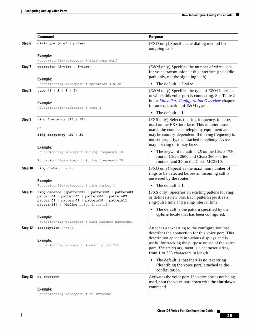
Configuring Analog Voice Ports How to Configure Analog Voice Ports
25Cisco IOS Voice Port Configuration Guide
Step 6 dial-type {dtmf | pulse}
Example:Router(config-voiceport)# dial-type dtmf
(FXO only) Specifies the dialing method for outgoing calls.
Step 7 operation {2-wire | 4-wire}
Example:Router(config-voiceport)# operation 4-wire
(E&M only) Specifies the number of wires used for voice transmission at this interface (the audio path only, not the signaling path).
• The default is 2-wire.
Step 8 type {1 | 2 | 3 | 5}
Example:Router(config-voiceport)# type 2
(E&M only) Specifies the type of E&M interface to which this voice port is connecting. See Table 2 in the Voice Port Configuration Overview chapter for an explanation of E&M types.
• The default is 1.
Step 9 ring frequency {25 | 50}
or
ring frequency {20 | 30}
Example:Router(config-voiceport)# ring frequency 50
Router(config-voiceport)# ring frequency 30
(FXS only) Selects the ring frequency, in hertz, used on the FXS interface. This number must match the connected telephony equipment and may be country-dependent. If the ring frequency is not set properly, the attached telephony device may not ring or it may buzz.
• The keyword default is 25 on the Cisco 1750 router, Cisco 2600 and Cisco 3600 series routers; and 20 on the Cisco MC3810.
Step 10 ring number number
Example:Router(config-voiceport)# ring number 1
(FXO only) Specifies the maximum number of rings to be detected before an incoming call is answered by the router.
• The default is 1.
Step 11 ring cadence {[pattern01 | pattern02 | pattern03 | pattern04 | pattern05 | pattern06 | pattern07 | pattern08 | pattern09 | pattern10 | pattern11 | pattern12] | [define pulse interval]}
Example:Router(config-voiceport)# ring cadence pattern01
(FXS only) Specifies an existing pattern for ring, or defines a new one. Each pattern specifies a ring-pulse time and a ring-interval time.
• The default is the pattern specified by the cptone locale that has been configured.
Step 12 description string
Example:Router(config-voiceport)# description 255
Attaches a text string to the configuration that describes the connection for this voice port. This description appears in various displays and is useful for tracking the purpose or use of the voice port. The string argument is a character string from 1 to 255 characters in length.
• The default is that there is no text string (describing the voice port) attached to the configuration.
Step 13 no shutdown
Example:Router(config-voiceport)# no shutdown
Activates the voice port. If a voice port is not being used, shut the voice port down with the shutdown command.
Command Purpose
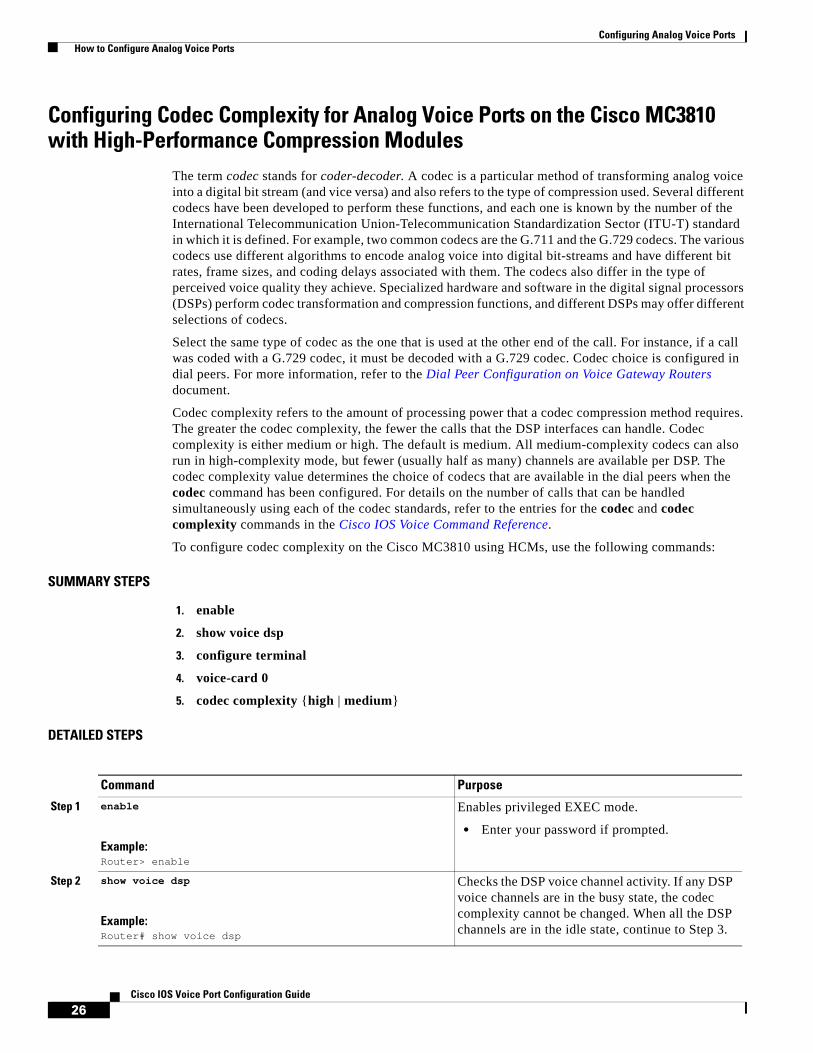
Configuring Analog Voice Ports How to Configure Analog Voice Ports
26Cisco IOS Voice Port Configuration Guide
Configuring Codec Complexity for Analog Voice Ports on the Cisco MC3810 with High-Performance Compression Modules
The term codec stands for coder-decoder. A codec is a particular method of transforming analog voice into a digital bit stream (and vice versa) and also refers to the type of compression used. Several different codecs have been developed to perform these functions, and each one is known by the number of the International Telecommunication Union-Telecommunication Standardization Sector (ITU-T) standard in which it is defined. For example, two common codecs are the G.711 and the G.729 codecs. The various codecs use different algorithms to encode analog voice into digital bit-streams and have different bit rates, frame sizes, and coding delays associated with them. The codecs also differ in the type of perceived voice quality they achieve. Specialized hardware and software in the digital signal processors (DSPs) perform codec transformation and compression functions, and different DSPs may offer different selections of codecs.
Select the same type of codec as the one that is used at the other end of the call. For instance, if a call was coded with a G.729 codec, it must be decoded with a G.729 codec. Codec choice is configured in dial peers. For more information, refer to the Dial Peer Configuration on Voice Gateway Routers document.
Codec complexity refers to the amount of processing power that a codec compression method requires. The greater the codec complexity, the fewer the calls that the DSP interfaces can handle. Codec complexity is either medium or high. The default is medium. All medium-complexity codecs can also run in high-complexity mode, but fewer (usually half as many) channels are available per DSP. The codec complexity value determines the choice of codecs that are available in the dial peers when the codec command has been configured. For details on the number of calls that can be handled simultaneously using each of the codec standards, refer to the entries for the codec and codec complexity commands in the Cisco IOS Voice Command Reference.
To configure codec complexity on the Cisco MC3810 using HCMs, use the following commands:
SUMMARY STEPS
1. enable
2. show voice dsp
3. configure terminal
4. voice-card 0
5. codec complexity {high | medium}
DETAILED STEPS
Command Purpose
Step 1 enable
Example:Router> enable
Enables privileged EXEC mode.
• Enter your password if prompted.
Step 2 show voice dsp
Example:Router# show voice dsp
Checks the DSP voice channel activity. If any DSP voice channels are in the busy state, the codec complexity cannot be changed. When all the DSP channels are in the idle state, continue to Step 3.

Configuring Analog Voice Ports How to Configure Analog Voice Ports
27Cisco IOS Voice Port Configuration Guide
CCDE, CCENT, Cisco Eos, Cisco Lumin, Cisco StadiumVision, the Cisco logo, DCE, and Welcome to the Human Network are trademarks; Changing the Way We Work, Live, Play, and Learn is a service mark; and Access Registrar, Aironet, AsyncOS, Bringing the Meeting To You, Catalyst, CCDA, CCDP, CCIE, CCIP, CCNA, CCNP, CCSP, CCVP, Cisco, the Cisco Certified Internetwork Expert logo, Cisco IOS, Cisco Press, Cisco Systems, Cisco Systems Capital, the Cisco Systems logo, Cisco Unity, Collaboration Without Limitation, EtherFast, EtherSwitch, Event Center, Fast Step, Follow Me Browsing, FormShare, GigaDrive, HomeLink, Internet Quotient, IOS, iPhone, iQ Expertise, the iQ logo, iQ Net Readiness Scorecard, iQuick Study, IronPort, the IronPort logo, LightStream, Linksys, MediaTone, MeetingPlace, MGX, Networkers, Networking Academy, Network Registrar, PCNow, PIX, PowerPanels, ProConnect, ScriptShare, SenderBase, SMARTnet, Spectrum Expert, StackWise, The Fastest Way to Increase Your Internet Quotient, TransPath, WebEx, and the WebEx logo are registered trademarks of Cisco Systems, Inc. and/or its affiliates in the United States and certain other countries.
All other trademarks mentioned in this document or Website are the property of their respective owners. The use of the word partner does not imply a partnership relationship between Cisco and any other company. (0804R)
Any Internet Protocol (IP) addresses used in this document are not intended to be actual addresses. Any examples, command display output, and figures included in the document are shown for illustrative purposes only. Any use of actual IP addresses in illustrative content is unintentional and coincidental.
© 2008 Cisco Systems, Inc. All rights reserved.
Step 3 configure terminal
Example:Router# configure terminal
Enters global configuration mode.
Step 4 voice-card 0
Example:Router(config)# voice-card 0
Enters voice-card configuration mode and specifies voice card 0.
Step 5 codec complexity {high | medium}
Example:Router(config-voicecard)# codec complexity high
Specifies codec complexity based on the codec standard being used. This setting restricts the codecs available in dial peer configuration. All voice cards in a router must use the same codec complexity setting.
Note If two HCMs are installed, this command configures both HCMs at once.
Command Purpose

Configuring Analog Voice Ports How to Configure Analog Voice Ports
28Cisco IOS Voice Port Configuration Guide
Americas Headquarters:Cisco Systems, Inc., 170 West Tasman Drive, San Jose, CA 95134-1706 USA
© 2008 Cisco Systems, Inc. All rights reserved.
Configuring Digital Voice Ports
The digital voice port commands discussed in this section configure channelized T1 or E1 connections; for information on ISDN connections, refer to the Cisco IOS ISDN Voice Configuration Guide.
The T1 or E1 lines that connect a telephony network to the digital voice ports on a router or access server contain channels for voice calls; a T1 line contains 24 full-duplex channels or timeslots, and an E1 line contains 30. The signal on each channel is transmitted at 64 kbps, a standard known as Digital Signal 0 (DS0); the channels are known as DS0 channels. The ds0-group command creates a logical voice port (a DS0 group) from some or all of the DS0 channels, which allows you to address those channels easily, as a group, in voice-port configuration commands.
Digital voice ports are found at the intersection of a packet voice network and a digital, circuit-switched telephone network. The digital voice port interfaces that connect the router or access server to T1 or E1 lines pass voice data and signaling between the packet network and the circuit-switched network.
Signaling is the exchange of information about calls and connections between two ends of a communication path. For instance, signaling communicates to the call’s endpoints whether a line is idle or busy, whether a device is on-hook or off-hook, and whether a connection is being attempted. An endpoint can be a central office (CO) switch, a PBX, a telephony device such as a telephone or fax machine, or a voice-equipped router acting as a gateway. There are two aspects to consider about signaling on digital lines: one aspect is the actual information about line and device states that is transmitted, and the second aspect is the method used to transmit the information on the digital lines.
The actual information about line and device states is communicated over digital lines using signaling methods that emulate the methods used in analog circuit-switched networks: Foreign Exchange Service (FXS), Foreign Exchange Office (FXO), and Ear and Mouth (E&M).
The method used to transmit the information describes the way that the emulated analog signaling is transmitted over digital lines, which may be common-channel signaling (CCS) or channel-associated signaling (CAS). CCS sends signaling information down a dedicated channel and CAS takes place within the voice channel itself. This chapter describes CAS, which is sometimes called robbed-bit signaling because user bandwidth is robbed by the network for signaling. A bit is taken from every sixth frame of voice data to communicate on- or off-hook status, wink, ground-start, dialed digits, and other information about the call.
In addition to setting up and tearing down calls, CAS provides the receipt and capture of dialed number identification (DNIS) and automatic number identification (ANI) information, which are used to support authentication and other functions. The main disadvantage of CAS is its use of user bandwidth to perform these signaling functions.
Configuring Digital Voice Ports Prerequisites for Configuring Digital Voice Ports
30Cisco IOS Voice Port Configuration Guide
For signaling to pass between the packet network and the circuit-switched network, both networks must use the same type of signaling. The voice ports on Cisco routers and access servers can be configured to match the signaling of most COs and PBXs, as explained in this document.
This chapter discusses the following topics:
• Prerequisites for Configuring Digital Voice Ports, page 30
• Information About Digital Voice Hardware, page 31
• How to Configure Digital T1/E1 Voice Ports, page 37
Prerequisites for Configuring Digital Voice PortsDigital T1 or E1 packet voice capability requires specific service, software, and hardware:
• Obtain T1 or E1 service from the service provider or from your PBX.
• Create your company’s dial plan.
• Establish a working telephony network based on your company’s dial plan.
• Establish a connection to the network LAN or WAN.
• Set up a working IP and Frame Relay or ATM network. For more information about configuring IP, refer to the Cisco IOS IP Configuration Guide.
• Install appropriate voice processing and voice interface hardware on the router. See the “Information About Digital Voice Hardware” section on page 31.
• (Cisco 2600 and Cisco 3600 series routers) For digital T1 packet voice trunk network modules, install Cisco IOS Release 12.2(1) or a later release. The minimum DRAM memory requirements are as follows:
– 32 MB, with one or two T1 lines
– 48 MB, with three or four T1 lines
– 64 MB, with five to ten T1 lines
– 128 MB, with more than ten T1 lines
The memory required for high-volume applications may be greater than that listed. Support for digital T1 packet voice trunk network modules is included in Plus feature sets. The IP Plus feature set requires 8 MB of flash memory; other Plus feature sets require 16 MB.
• (Cisco 2600 and Cisco 3600 series routers) For digital E1 packet voice trunk network modules, install Cisco IOS Release 12.2(1) or a later release. The minimum DRAM memory requirements are:
– 48 MB, with one or two E1s
– 64 MB, with three to eight E1s
– 128 MB, with 9 to 12 E1s
For high-volume applications, the memory required may be greater than these minimum values. Support for digital E1 packet voice trunk network modules is included in Plus feature sets. The IP Plus feature set requires 16 MB of flash memory.
• Before you can run the IP Communications High-Density Digital Voice/Fax Network Module feature on T1/E1 interfaces, you must install an IP Plus image (minimum) of Cisco IOS Release 12.3(7)T or a later release.
• (Cisco MC3810 concentrators) HCMs require Cisco IOS Release 12.2(1) or a later release.
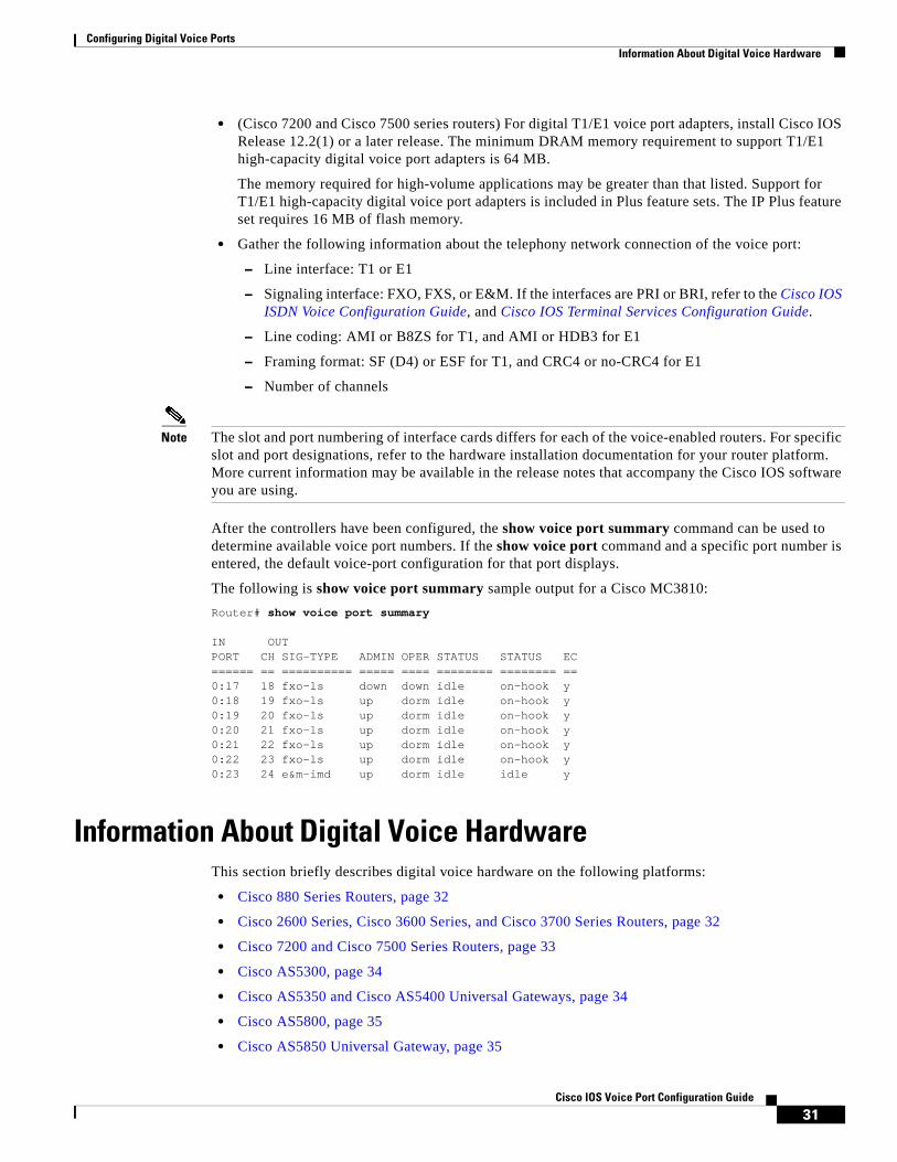
Configuring Digital Voice Ports Information About Digital Voice Hardware
31Cisco IOS Voice Port Configuration Guide
• (Cisco 7200 and Cisco 7500 series routers) For digital T1/E1 voice port adapters, install Cisco IOS Release 12.2(1) or a later release. The minimum DRAM memory requirement to support T1/E1 high-capacity digital voice port adapters is 64 MB.
The memory required for high-volume applications may be greater than that listed. Support for T1/E1 high-capacity digital voice port adapters is included in Plus feature sets. The IP Plus feature set requires 16 MB of flash memory.
• Gather the following information about the telephony network connection of the voice port:
– Line interface: T1 or E1
– Signaling interface: FXO, FXS, or E&M. If the interfaces are PRI or BRI, refer to the Cisco IOS ISDN Voice Configuration Guide, and Cisco IOS Terminal Services Configuration Guide.
– Line coding: AMI or B8ZS for T1, and AMI or HDB3 for E1
– Framing format: SF (D4) or ESF for T1, and CRC4 or no-CRC4 for E1
– Number of channels
Note The slot and port numbering of interface cards differs for each of the voice-enabled routers. For specific slot and port designations, refer to the hardware installation documentation for your router platform. More current information may be available in the release notes that accompany the Cisco IOS software you are using.
After the controllers have been configured, the show voice port summary command can be used to determine available voice port numbers. If the show voice port command and a specific port number is entered, the default voice-port configuration for that port displays.
The following is show voice port summary sample output for a Cisco MC3810:
Router# show voice port summary
IN OUTPORT CH SIG-TYPE ADMIN OPER STATUS STATUS EC====== == ========== ===== ==== ======== ======== ==0:17 18 fxo-ls down down idle on-hook y0:18 19 fxo-ls up dorm idle on-hook y0:19 20 fxo-ls up dorm idle on-hook y0:20 21 fxo-ls up dorm idle on-hook y0:21 22 fxo-ls up dorm idle on-hook y0:22 23 fxo-ls up dorm idle on-hook y0:23 24 e&m-imd up dorm idle idle y
Information About Digital Voice HardwareThis section briefly describes digital voice hardware on the following platforms:
• Cisco 880 Series Routers, page 32
• Cisco 2600 Series, Cisco 3600 Series, and Cisco 3700 Series Routers, page 32
• Cisco 7200 and Cisco 7500 Series Routers, page 33
• Cisco AS5300, page 34
• Cisco AS5350 and Cisco AS5400 Universal Gateways, page 34
• Cisco AS5800, page 35
• Cisco AS5850 Universal Gateway, page 35

Configuring Digital Voice Ports Information About Digital Voice Hardware
32Cisco IOS Voice Port Configuration Guide
• Cisco Catalyst 6500 Series Switches and Cisco 7600 Series Routers with Communication Media Modules, page 36
• Cisco MC3810, page 36
Note For current information about supported hardware, refer to the release notes for the platform and Cisco IOS release you are using.
Cisco 880 Series RoutersBeginning with Cisco IOS Release 12.4(15)XZ, the Cisco 880 series fixed router platforms support the implementation of analog (FXS/DID/FXO) and digital (BRI S/T) voice ports. The IAD881B, IAD881F, IAD888B, and IAD888F models support voice interface FXS or BRI. The IAD881F and IAD888F models have four FXS ports and the IAD881B and IAD888B models support two ports for ISDN BRI digital voice interface.
In the IAD881B and IAD888B models, the voice BRI interface presents an ISDN S/T interface to connect either to an NT1 terminating an ISDN telephone network (TE-side) or to a TE user device such as an ISDN telephone or PBX (NT-side). In the IAD881B and IAD888B models, the BRI interface is available as the primary voice interface and is intended to be connected to a PBX (network side trunk). All the voice interfaces are onboard though they are recognized as a 4-port FXS VIC and a 2-port BRI VIC in order to leverage existing voice drivers.
Note If the primary voice interface is FXS and the backup is BRI, then ports 0, 1, 2, and 3 are analog voice ports, and ports 4 and 5 are digital. If the primary voice interface is BRI, then ports 1, 2, 3, and 4 are digital.
The C881and C888 SRST models automatically detect a failure occuring in the network and initiate a process to auto-configure the router. This process provides call-processing backup redundancy for the IP and FXS phones and helps to ensure that telephony capabilities stay operational. All the IP or analog phones hanging off of a telecommuter site are controlled by the headquarters office call control (Cisco Unified CallManager or CallManager Express). In case of a WAN failure, the telecommuter router allows all phones to re-register to it in SRST mode and allow all inbound and outbound dialing to be routed off to the PSTN (using back up FXO or BRI port). Upon restoration of WAN connectivity, the system automatically shifts call processing back to the primary Cisco Unified Call Manager cluster.
Cisco 2600 Series, Cisco 3600 Series, and Cisco 3700 Series RoutersDigital voice hardware on Cisco 2600 series, Cisco 3600 series, and Cisco 3700 series modular access routers includes the high-density voice (HDV) network module and the multiflex trunk (MFT) voice/WAN interface card (VWIC). When an HDV is used in conjunction with an MFT and packet voice DSP modules (PVDMs), the HDV module is also called a digital packet voice trunk network module. The digital T1 or E1 packet voice trunk network module supports T1 or E1 applications, including fractional use. The T1 version integrates a fully managed DSU/CSU, and the E1 version includes a fully managed DSU. The digital T1 or E1 packet voice trunk network module provides per-channel T1 or E1 data rates of 64 or 56 kbps for WAN services (Frame Relay or leased line).
Digital T1 or E1 packet voice trunk network modules allow enterprises or service providers, using the voice-equipped routers as customer premises equipment (CPE), to deploy digital voice and fax relay. These network modules receive constant bit-rate telephony information over T1 or E1 interfaces and

Configuring Digital Voice Ports Information About Digital Voice Hardware
33Cisco IOS Voice Port Configuration Guide
convert that information to a compressed format so that it can be sent over a packet network. The digital T1 or E1 packet voice trunk network modules can connect either to a PBX (or similar telephony device) or to a CO to provide PSTN connectivity.
The MFT VWICs that are used in the packet voice trunk network modules are available in one- and two-port configurations for T1 and for E1, and in two-port configurations with drop-and-insert capability for T1 and E1. MFTs support the following kinds of traffic:
• Data. As WICs for T1 or E1 applications, including fractional data line use, the T1 version includes a fully managed DSU/CSU, and the E1 version includes a fully managed DSU.
• Packet voice. As VWICs included with the digital T1 or E1 packet voice trunk network module to provide connections to PBXs and COs, the MFTs enable packet voice applications.
• Multiplexed voice and data. Some two-port T1 or E1 VWICs can provide drop-and-insert multiplexing services with integrated DSU/CSUs. For example, when used with a digital T1 packet voice trunk network module, drop-and-insert allows 64-kbps DS0 channels to be taken from one T1 and digitally cross-connected to 64-kbps DS0 channels on another T1. Drop and insert, sometimes called time-division multiplex (TDM) cross-connect, uses circuit switching rather than the digital signal processors (DSPs) that VoIP technology employs. (Drop-and-insert is described in the Trunk Management Features document.
The digital T1 or E1 packet voice trunk network module contains five 72-pin Single In-line Memory Module (SIMM) sockets or banks, numbered 0 through 4, for PVDMs. Each socket can be filled with a single 72-pin PVDM, and there must be at least one packet voice data module (PVDM-12) in the network module to process voice calls. Each PVDM holds three DSPs, so with five PVDM slots populated, a total of 15 DSPs are provided. High-complexity codecs support two simultaneous calls on each DSP, and medium-complexity codecs support four calls on each DSP. A digital T1 or E1 packet voice trunk network module can support the following numbers of channels:
• When the digital T1 or E1 packet voice trunk network module is configured for high-complexity codec mode, up to six voice or fax calls can be completed per PVDM-12, using the following codecs: G.711, G.726, G.729, G729 Annex A (E1), G.729 Annex B, G.723.1, G723.1 Annex A (T1), G.728, and fax relay.
• When the digital T1 or E1 packet voice trunk network module is configured for medium-complexity codec mode, up to 12 voice or fax calls can be completed per PVDM-12, using the following codecs: G.711, G.726, G.729 Annex A, G.729 Annex B with Annex A, and fax relay.
For more information, refer to the following:
• Hardware installation documents for Cisco 2600 series
• Hardware installation documents for Cisco 3600 series
• Cisco Network Modules Hardware Installation Guide
• Cisco Interface Cards Installation Guide
Cisco 7200 and Cisco 7500 Series RoutersCisco 7200 and Cisco 7500 series routers support multimedia routing and bridging with a wide variety of protocols and media types. The Cisco 7000 family Versatile Interface Processor (VIP) is based on a reduced instruction set computing (RISC) engine optimized for I/O functions. To this engine are attached one or two port adapters or daughter boards, which provide the media-specific interfaces to the network. The network interfaces provide connections between the routers’ peripheral component interconnect (PCI) buses and external networks. Port adapters can be placed in any available port adapter slot, in any desired combination.

Configuring Digital Voice Ports Information About Digital Voice Hardware
34Cisco IOS Voice Port Configuration Guide
T1/E1 high-capacity digital voice port adapters for Cisco 7200 and Cisco 7500 series routers allow enterprises or service providers, using the equipped routers as CPE, to deploy digital voice and fax relay. These port adapters receive constant bit-rate telephony information over T1/E1 interfaces and can convert that information to a compressed format for transmission as VoIP. Two types of digital voice port adapters are supported on Cisco 7200 and Cisco 7500 series routers: two-port high-capacity (up to 48 or 120 channels of compressed voice, depending on codec choice), and two-port moderate capacity (up to 24 or 48 channels of compressed voice). These single-width port adapters incorporate two universal ports configurable for either T1 or E1 connection, for use with high-performance DSPs. Integrated CSU/DSUs, echo cancellation, and DS0 drop-and-insert functionality eliminate the need for external line termination devices and multiplexers.
For more information, refer to the following publications:
• Cisco 7200 VXR Installation and Configuration Guide
• Cisco 7500 Series Installation and Configuration Guide
• Two-Port T1/E1 Moderate-Capacity and High-Capacity Digital Voice Port Adapter Installation and Configuration
Note For current information about supported hardware, refer to the release notes for the platform and Cisco IOS release you are using.
Cisco AS5300 The Cisco AS5300 includes three expansion slots. One slot is for either an Octal T1/E1/PRI feature card (eight ports) or a Quad T1/E1/PRI feature card (four ports), and the other two can be used for voice/fax or modem feature cards. Because a single voice/fax feature card (VFC) can support up to 48 (T1) or 60 (E1) voice calls, the Cisco AS5300 can support a total of 96 or 120 simultaneous voice calls.
Cisco AS5300 VFCs are coprocessor cards, each with a powerful reduced instruction set computing (RISC) engine and dedicated, high-performance DSPs to ensure predictable, real-time voice processing. The design couples this coprocessor with direct access to the Cisco AS5300 routing engine for streamlined packet forwarding.
For more information, refer to the following publications:
• Hardware installation documents for Cisco AS5300
• Configuration documents for Cisco AS5300
Cisco AS5350 and Cisco AS5400 Universal GatewaysThe Cisco AS5350 and Cisco AS5400 universal gateways are versatile data and voice communications platforms that provide the functions of a gateway, router, and digital modems in a single modular chassis.
The gateways are intended for Internet service providers (ISPs), telecommunications carriers, and other service providers that offer managed Internet connections, and also medium to large sites that provide both digital and analog access to users on an enterprise network.
The cards that reside in the Cisco AS5350 and AS5400 chassis, sometimes referred to as dial feature cards (DFCs), are of two types: trunk cards, which provide an E1, T1, or T3 interface, and universal port cards, which host the universal DSPs that dynamically handle voice, dial, and fax calls.
For more information, refer to the following publications:
Configuring Digital Voice Ports Information About Digital Voice Hardware
35Cisco IOS Voice Port Configuration Guide
• Cisco AS5350 and AS5400 Universal Gateway Card Installation Guide
• Cisco AS5350 and AS5400 Universal Gateway Software Configuration Guide
Cisco AS5800 The Cisco AS5800 has two primary system components: the Cisco 5814 dial shelf (DS), which holds channelized trunk cards and connects to the PSTN, and the Cisco 7206 router shelf (RS), which holds port adapters and connects to the IP backbone.
The dial shelf acts as the access concentrator by accepting and consolidating all types of remote traffic, including voice, dial-in analog and digital ISDN data, and industry-standard WAN and remote connection types. The dial shelf also contains controller cards voice feature cards, modem feature cards, trunk cards, and dial shelf interconnect cards.
One or two dial shelf controllers (DSCs) provide clock and power control to the dial shelf cards. Each DSC contains a block of logic that is referred to as the common logic and system clocks. This block of logic can use a variety of sources to generate the system timing, including an E1 or T1/T3 input signal from the BNC connector on the front panel of the DSC. The configuration commands for the master clock specify the various clock sources and a priority for each source (see the “Clock Sources on Digital T1/E1 Voice Ports” section on page 49).
The Cisco AS5800 voice feature card is a multi-DSP coprocessing board and software package that adds VoIP capabilities to the Cisco AS5800 platform. The Cisco AS5800 voice feature card, when used with other cards such as LAN/WAN and modem cards, provides a gateway for up to 192 packetized voice/fax calls and 360 data calls per card. A Cisco AS5800 can support up to 1344 voice calls in split-dial-shelf configuration with two 7206VXR router shelves.
For more information, refer to the following publications:
• Cisco AS5800 Access Server Hardware Installation Guide
• Cisco AS5800 Operation, Administration, Maintenance, and Provisioning Guide
Cisco AS5850 Universal GatewayThe Cisco AS5850 is a high-density ISDN and port WAN aggregation system that provides both digital and analog call termination. It is intended to be used in service-provider dial point-of-presence (POP) or centralized-enterprise dial environments. The feature cards and the route switch controller (RSC) communicate over a nonblocking interconnect that supports Fast Ethernet and full-duplex service.
The Cisco AS5850 contains ingress interfaces (CT3 and CE1/PRI) that terminate ISDN and modem calls and break out individual calls (DS0s) from the appropriate telco services. Digital or ISDN calls are terminated on the trunk-card HDLC controllers, and analog calls are sent to port resources on the same card or on separate port cards. As a result, any DS0 can be mapped to any HDLC controller or port module. Unlike the Cisco AS5800, trunk-termination and port-handling services can be performed on the same card in the same slot.
For more information, refer to the following publications:
• Cisco AS5850 Hardware Installation Guide
• Cisco AS5850 Universal Gateway Operations, Administration, Maintenance, and Provisioning Guide

Configuring Digital Voice Ports Information About Digital Voice Hardware
36Cisco IOS Voice Port Configuration Guide
Cisco Catalyst 6500 Series Switches and Cisco 7600 Series Routers with Communication Media Modules
The Communication Media Module (CMM) acts as the VoIP gateway and media services module by using Media Gateway Control Protocol (MGCP), H.323, and SIP protocols with Cisco CallManager and other call agents. The CMM can support single or multiple Cisco CallManagers in an IP communication network.
These VoIP gateway and media services features are provided through the four different types of CMM port adapters as shown in Table 1.
For specific configuration information for the Catalyst 6500 series and Cisco 7600 series, see the following documents:
• Cisco 6500 and 7600 series Manager Installation Guide, Release 2.1
• Cisco 6500 and 7600 series Manager User Guide, Release 2.1
• Cisco 6500 and 7600 series Manager Release Notes, Release 2.1
For specific installation and configuration information for the CMM, see the following document:
• Catalyst 6500 Series and Cisco 7600 Series CMM Installation and Verification Note
• Cisco Communication Media Module Voice Features for Catalyst 6500 Series and Cisco 7600 Series
Cisco MC3810 To support a T1 or E1 digital voice interface, the Cisco MC3810 must be equipped with a digital voice interface card (DVM). The DVM interfaces with a digital PBX, channel bank, or video codec. It supports up to 24 channels of compressed digital voice at 8 kbps, or it can cross-connect channelized data from user equipment directly onto the router’s trunk port for connection to a carrier network.
Table 1 CMM Port Adapters
CMM Port Adapters Description
• WS-SVC-CMM-6T1
• WS-SVC-CMM-6E1
The 6-port T1 and E1 port adapters have onboard digital signal processor (DSP) resources that allow you to connect the interfaces to the public switched telephone network (PSTN) or private branch exchanges (PBXs) through T1/E1R2 Channel Associated Signaling (CAS) or T1/E1 ISDN Primary Rate Interface (PRI). The DSP resources on the port adapters provide packetization, echo cancellation, fax relay, tone detection and generation, concealment, and jitter buffers.
WS-SVC-CMM-24FXS The 24-port FXS port adapter has onboard DSP resources that allow the FXS interfaces to emulate the central office (CO) or PBX analog trunk lines by providing service to analog phones and fax machines, which behave as if connected to a standard CO or PBX line.
WS-SVC-CMM-ACT The ACT port adapter has DSP resources for conferencing, transcoding, and media termination point (MTP) services. A CMM with an ACT port adapter supports a single conference with up to 64 participants. A single ACT port adapter supports up to 128 audio conference ports, which can be distributed among different conferences of two or more parties.

Configuring Digital Voice Ports How to Configure Digital T1/E1 Voice Ports
37Cisco IOS Voice Port Configuration Guide
The DVM is available with a balanced interface using an RJ-48 connector or with an unbalanced interface using BNC connectors.
Optional HCMs can replace standard VCMs to operate according to the voice compression coding algorithm (codec) specified when the Cisco MC3810 is configured. The HCM2 provides 4 voice channels at high codec complexity and 8 channels at medium complexity. The HCM6 provides 12 voice channels at high complexity and 24 channels at medium complexity. You can install one or two HCMs in a Cisco MC3810, but an HCM cannot be combined with a VCM in the same chassis.
For more information, refer to the following publications:
• Cisco MC3810 Multiservice Concentrator Hardware Installation Guide
• Cisco MC3810 Multiservice Concentrator Configuration Guide
How to Configure Digital T1/E1 Voice PortsThis section describes commands for the basic configuration of digital voice ports. Make sure you have all the data recommended in the “Prerequisites for Configuring Digital Voice Ports” section on page 30 before starting these procedures.
The basic steps for configuring digital voice ports are described in the next three sections. They are grouped by the configuration mode from which they are executed, as follows:
• Configuring Codec Complexity on Digital T1/E1 Voice Ports, page 38
Codec complexity refers to the amount of processing power assigned to a codec method on a voice port. On most router platforms that support codec complexity, codec complexity is selected in voice-card configuration mode, although it is selected in DSP interface mode on the Cisco 7200 and Cisco 7500 series.
• Configuring Controller Settings for Digital T1/E1 Voice Ports, page 47
Specific line characteristics must be configured to match those of the PSTN line that is being connected to the voice port. These are typically configured in controller configuration mode.
• Configuring Basic Voice Port Parameters for Digital T1/E1 Voice Ports, page 57
Voice-port configuration mode allows many of the basic voice call attributes to be configured to match those of the PSTN or PBX connection being made on this voice port.
In addition to the basic voice port parameters, there are commands that allow for the fine- tuning of the voice port configurations or for configuration of optional features. In most cases, the default values for these commands are sufficient for establishing voice port configurations. If it is necessary to change some of these parameters to improve voice quality or to match parameters in proprietary PBXs to which you are connecting, use the commands in the “Fine-Tuning Analog and Digital Voice Ports” section on page 51.
After voice port configuration, make sure the ports are operational by following the steps described in these chapters:
• Verifying Analog and Digital Voice-Port Configurations, page 125
• Troubleshooting Analog and Digital Voice Port Configurations, page 137
For more information on voice port commands, refer to the Cisco IOS Voice Command Reference.
Configuring Digital Voice Ports How to Configure Digital T1/E1 Voice Ports
38Cisco IOS Voice Port Configuration Guide
Configuring Codec Complexity on Digital T1/E1 Voice PortsThis section provides two configuration task tables: one for the Cisco 2600, Cisco 3600, and Cisco 3700 series routers and the Cisco MC3810 concentrator, which use voice-card configuration mode, and the second for the Cisco 7200 and Cisco 7500 series routers, which use DSP interface configuration mode. The task tables can be found in the following sections:
• Configuring Codec Complexity on Cisco 880 Series, Cisco 2600, Cisco 3600, Cisco 3700 Series and Cisco MC3810, page 38
• Configuring Codec Complexity on Cisco 7200 Series and Cisco 7500 Series Routers, page 45
Configuring Codec Complexity on Cisco 880 Series, Cisco 2600, Cisco 3600, Cisco 3700 Series and Cisco MC3810
On the Cisco 880 series, Cisco 2600, Cisco 3600, Cisco 3700, Cisco 7200, and Cisco 7500 routers, codec complexity can be configured separately for each T1/E1 digital packet voice trunk network module or port adapter. On a Cisco MC3810, the codec complexity setting applies to both HCMs if two HCMs are installed.
Note On Cisco 2600, Cisco 3600, and Cisco 3700 series routers with digital T1/E1 packet voice trunk network modules, codec complexity cannot be configured if DS0 or PRI groups are configured. If DS0 or PRI groups are configured, see the “Changing Codec Complexity on Cisco 880 Series, Cisco 2600 Series, Cisco 3600 Series, Cisco 3700 Series, and Cisco MC3810” section on page 39.
To configure codec complexity for digital voice ports on the Cisco 880 series, Cisco 2600 series, Cisco 3600 series, and Cisco 3700 series routers, and for voice ports on HCMs on the Cisco MC3810, use the following commands:
SUMMARY STEPS
1. enable
2. show voice dsp
3. configure terminal
4. voice-card slot
5. codec complexity {high | medium}
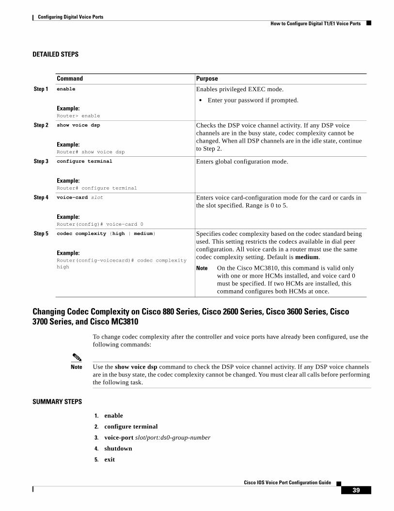
Configuring Digital Voice Ports How to Configure Digital T1/E1 Voice Ports
39Cisco IOS Voice Port Configuration Guide
DETAILED STEPS
Changing Codec Complexity on Cisco 880 Series, Cisco 2600 Series, Cisco 3600 Series, Cisco 3700 Series, and Cisco MC3810
To change codec complexity after the controller and voice ports have already been configured, use the following commands:
Note Use the show voice dsp command to check the DSP voice channel activity. If any DSP voice channels are in the busy state, the codec complexity cannot be changed. You must clear all calls before performing the following task.
SUMMARY STEPS
1. enable
2. configure terminal
3. voice-port slot/port:ds0-group-number
4. shutdown
5. exit
Command Purpose
Step 1 enable
Example:Router> enable
Enables privileged EXEC mode.
• Enter your password if prompted.
Step 2 show voice dsp
Example:Router# show voice dsp
Checks the DSP voice channel activity. If any DSP voice channels are in the busy state, codec complexity cannot be changed. When all DSP channels are in the idle state, continue to Step 2.
Step 3 configure terminal
Example:Router# configure terminal
Enters global configuration mode.
Step 4 voice-card slot
Example:Router(config)# voice-card 0
Enters voice card-configuration mode for the card or cards in the slot specified. Range is 0 to 5.
Step 5 codec complexity {high | medium}
Example:Router(config-voicecard)# codec complexity high
Specifies codec complexity based on the codec standard being used. This setting restricts the codecs available in dial peer configuration. All voice cards in a router must use the same codec complexity setting. Default is medium.
Note On the Cisco MC3810, this command is valid only with one or more HCMs installed, and voice card 0 must be specified. If two HCMs are installed, this command configures both HCMs at once.

Configuring Digital Voice Ports How to Configure Digital T1/E1 Voice Ports
40Cisco IOS Voice Port Configuration Guide
6. controller {t1 | e1} slot/port
7. no ds0-group ds0-group-number
or
no pri-group timeslots timeslot-list
8. exit
9. voice-card slot
10. codec complexity {high | medium} [ecan-extended]
11. exit
12. Repeat Step 6, then continue with Step 13.
13. ds0-group ds0-group-number timeslots timeslot-list type {e&m-immediate | e&m-delay | e&m-wink-start | fxs-ground-start | fxs-loop-start | fxo-ground-start | fxo-loop-start}
or
pri-group timeslots timeslot-list
14. exit
15. Repeat Step 3, then continue with Step 16.
16. no shutdown
17. end
DETAILED STEPS
Command or Action Purpose
Step 1 enable
Example:Router> enable
Enables privileged EXEC mode.
• Enter your password if prompted.
Step 2 configure terminal
Example:Router# configure terminal
Enters global configuration mode.

Configuring Digital Voice Ports How to Configure Digital T1/E1 Voice Ports
41Cisco IOS Voice Port Configuration Guide
Step 3 voice-port slot/port:ds0-group-number
Example:Router(config)# voice-port 1/0:23
Enters voice-port configuration mode on the selected slot, port, and DS0 group.
Note The syntax of this command is platform-specific. For the syntax for your platform, refer to the Cisco IOS Voice CommandReference.
Note For the Cisco 880 series platforms, the command syntax does not include a slot number, only the port is identified.If the primary voice interface is FXS and the backup is BRI, then ports 0, 1, 2, and 3 are analog voice ports, and ports 4 and 5 are digital. If the primary voice interface is BRI, then ports 1, 2, 3, and 4 are digital.
Step 4 shutdown
Example:Router(config-voiceport)# shutdown
Shuts down all voice ports assigned to the T1 interface on the voice card.
Step 5 exit
Example:Router(config-voiceport)# exit
Exits voice-port configuration mode.
Step 6 controller {t1 | e1} slot/port
Example:Router(config)# controller t1 1/0
Enters controller configuration mode on the T1 controller on the selected slot and port.
Step 7 no ds0-group ds0-group-number
or
no pri-group timeslots timeslot-list
Example:Router(config-controller)# no ds0-group 1
Example:Router(config-controller)# no pri-group timeslots 1,7,9
Removes the related DS0 groups.
or
Removes the related PRI group.
Step 8 exit
Example:Router(config-controller) exit
Exits controller configuration mode and returns to global configuration mode.
Step 9 voice-card slot
Example:Router(config)# voice-card 1
Enters voice-card configuration mode on the specified slot.
• slot—Slot number of the voice card. Range is 0 to 6, depending on platform.
Command or Action Purpose

Configuring Digital Voice Ports How to Configure Digital T1/E1 Voice Ports
42Cisco IOS Voice Port Configuration Guide
Step 10 codec complexity {high | medium} [ecan-extended]
Example:Router(voice-card)# codec complexity high ecan-extended
Changes codec complexity or changes the echo canceller (EC) from the proprietary Cisco G.165 EC to the G.168 extended EC.
• high—Supports up to six voice or fax calls per DSP module (PVDM-12), using the codecs: G.723, G.728, G.729, G.729 Annex B, GSMEFR, GSMFR, fax relay, or any of the medium complexity codecs.
• medium—Supports up to 12 voice or fax calls per DSP module (PVDM-12), using the codecs: G.711, G.726, G.729 Annex A, G.729 Annex A with Annex B, and fax relay. Default value.
• ecan-extended—(Optional) Selects the G.168 extended echo canceller. For more information, see the “How to Configure the Extended G.168 Echo Canceller” section.
Specifying the codec complexity restricts the codecs available in dial-peer configuration mode. All voice cards in a gateway must use the same codec complexity.
Step 11 exit
Example:Router(voice-card) exit
Exits voice-card configuration mode and returns to global configuration mode.
Step 12 Repeat Step 6, then continue with Step 13. —
Step 13 ds0-group ds0-group-number timeslots timeslot-list type {e&m-immediate | e&m-delay | e&m-wink-start | fxs-ground-start | fxs-loop-start | fxo-ground-start | fxo-loop-start}
or
pri-group timeslots timeslot-list
Example:Router(config-controller)# ds0-group 0 timeslots 1-24 type e&m-wink-start
Example:Router(config-controller)# pri-group timeslots 1,7,9
Defines the T1 or E1 channels for use by compressed voice calls and the signaling method that the router uses to connect to the PBX or CO.
Note If you are configuring PRI groups instead of DS0 groups, omit this step and proceed to Step 15.
or
Specifies an ISDN PRI on a channelized T1 or E1 controller.
Note When configuring PRI groups, you must also configure the isdn switch-type command. Also, only one PRI group can be configured on a controller.
Step 14 exit
Example:Router(config-controller)# exit
Exits controller configuration mode and completes the process for adding back the PRI groups or DS0 groups.
Step 15 Repeat Step 3, then continue with Step 16. —
Command or Action Purpose
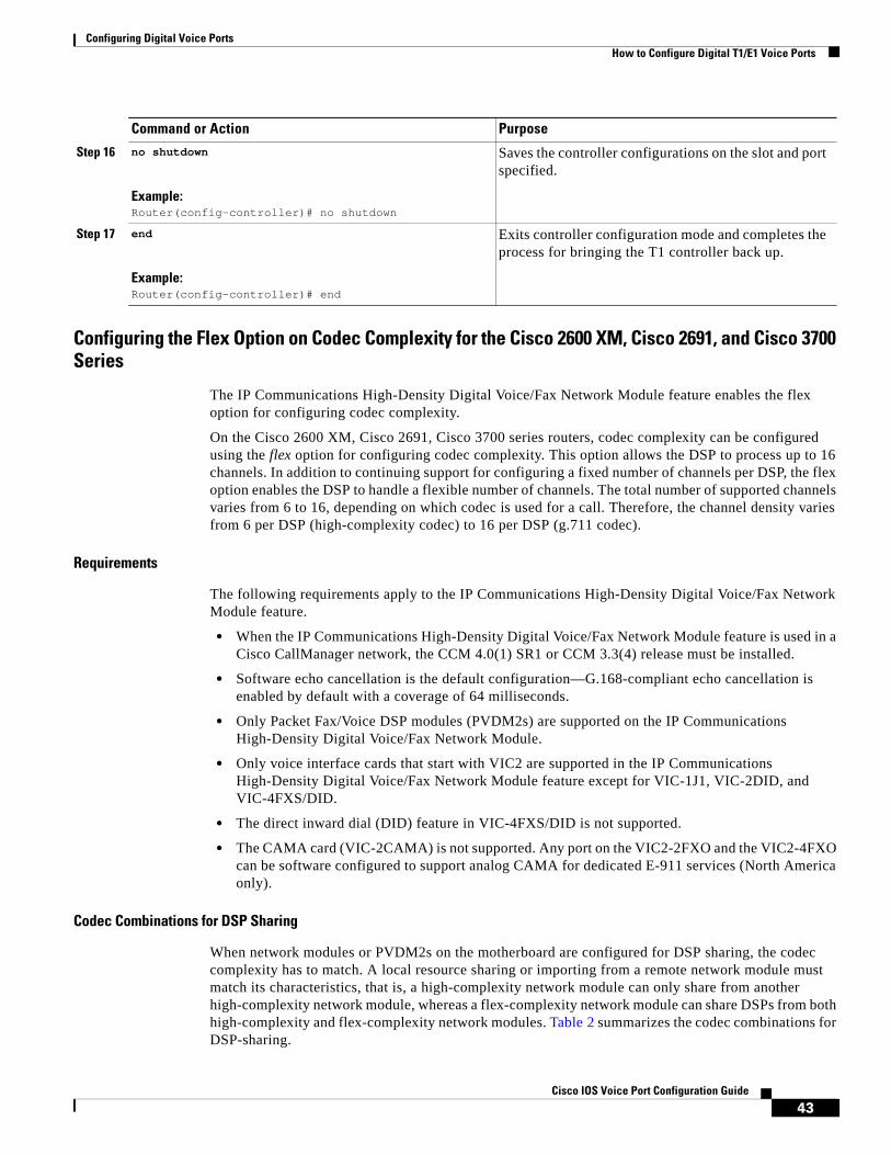
Configuring Digital Voice Ports How to Configure Digital T1/E1 Voice Ports
43Cisco IOS Voice Port Configuration Guide
Configuring the Flex Option on Codec Complexity for the Cisco 2600 XM, Cisco 2691, and Cisco 3700 Series
The IP Communications High-Density Digital Voice/Fax Network Module feature enables the flex option for configuring codec complexity.
On the Cisco 2600 XM, Cisco 2691, Cisco 3700 series routers, codec complexity can be configured using the flex option for configuring codec complexity. This option allows the DSP to process up to 16 channels. In addition to continuing support for configuring a fixed number of channels per DSP, the flex option enables the DSP to handle a flexible number of channels. The total number of supported channels varies from 6 to 16, depending on which codec is used for a call. Therefore, the channel density varies from 6 per DSP (high-complexity codec) to 16 per DSP (g.711 codec).
Requirements
The following requirements apply to the IP Communications High-Density Digital Voice/Fax Network Module feature.
• When the IP Communications High-Density Digital Voice/Fax Network Module feature is used in a Cisco CallManager network, the CCM 4.0(1) SR1 or CCM 3.3(4) release must be installed.
• Software echo cancellation is the default configuration—G.168-compliant echo cancellation is enabled by default with a coverage of 64 milliseconds.
• Only Packet Fax/Voice DSP modules (PVDM2s) are supported on the IP Communications High-Density Digital Voice/Fax Network Module.
• Only voice interface cards that start with VIC2 are supported in the IP Communications High-Density Digital Voice/Fax Network Module feature except for VIC-1J1, VIC-2DID, and VIC-4FXS/DID.
• The direct inward dial (DID) feature in VIC-4FXS/DID is not supported.
• The CAMA card (VIC-2CAMA) is not supported. Any port on the VIC2-2FXO and the VIC2-4FXO can be software configured to support analog CAMA for dedicated E-911 services (North America only).
Codec Combinations for DSP Sharing
When network modules or PVDM2s on the motherboard are configured for DSP sharing, the codec complexity has to match. A local resource sharing or importing from a remote network module must match its characteristics, that is, a high-complexity network module can only share from another high-complexity network module, whereas a flex-complexity network module can share DSPs from both high-complexity and flex-complexity network modules. Table 2 summarizes the codec combinations for DSP-sharing.
Step 16 no shutdown
Example:Router(config-controller)# no shutdown
Saves the controller configurations on the slot and port specified.
Step 17 end
Example:Router(config-controller)# end
Exits controller configuration mode and completes the process for bringing the T1 controller back up.
Command or Action Purpose
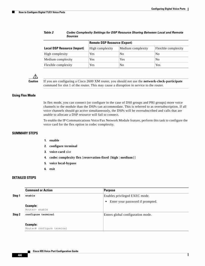
Configuring Digital Voice Ports How to Configure Digital T1/E1 Voice Ports
44Cisco IOS Voice Port Configuration Guide
Caution If you are configuring a Cisco 2600 XM router, you should not use the network-clock-participate command for slot 1 of the router. This may cause a disruption in service to the router.
Using Flex Mode
In flex mode, you can connect (or configure in the case of DS0 groups and PRI groups) more voice channels to the module than the DSPs can accommodate. This is referred to as oversubscription. If all voice channels should go active simultaneously, the DSPs will be oversubscribed and calls that are unable to allocate a DSP resource will fail to connect.
To enable the IP Communications Voice/Fax Network Module feature, perform this task to configure the voice card for the flex option in codec complexity.
SUMMARY STEPS
1. enable
2. configure terminal
3. voice-card slot
4. codec complexity flex [reservation-fixed {high | medium}]
5. voice local-bypass
6. exit
DETAILED STEPS
Table 2 Codec Complexity Settings for DSP Resource Sharing Between Local and Remote
Sources
Local DSP Resource (Import)
Remote DSP Resource (Export)
High complexity Medium complexity Flexible complexity
High complexity Yes No No
Medium complexity Yes Yes No
Flexible complexity Yes No Yes
Command or Action Purpose
Step 1 enable
Example:Router> enable
Enables privileged EXEC mode.
• Enter your password if prompted.
Step 2 configure terminal
Example:Router# configure terminal
Enters global configuration mode.

Configuring Digital Voice Ports How to Configure Digital T1/E1 Voice Ports
45Cisco IOS Voice Port Configuration Guide
Configuring Codec Complexity on Cisco 7200 Series and Cisco 7500 Series Routers
On Cisco 7200 series and Cisco 7500 series routers, codec complexity is configured in the DSP interface.
Step 3 voice-card slot
Example:Router(config)# voice-card 1
Enters voice-card configuration mode and specifies the slot location.
• For the slot argument, specify a value from 1 to 4, depending on your router.
Step 4 codec complexity flex [reservation-fixed {high | medium}]
Example:Router(config-voicecard)# codec complexity flex
Specifies the flex option for codec complexity.
• flex—Up to 16 calls can be completed per DSP. The number of supported calls varies from 6 to 16, depending on the codec used for a call. In this mode, reservation for analog VICs may be needed for certain appplications such as CAMA E-911 calls because oversubscription of DSPs is possible. If this is true, then the reservation-fixed option may be enabled. There is no reservation by default.
– reservation-fixed—Appears as an option only when there is an analog VIC present. Ensures that sufficient DSP resources are available to handle a call. If you enter this keyword, then specify if the complexity should be high or medium.
Note You cannot change codec complexity while DS0 groups are defined. If they are already set up, perform the steps in the “Changing Codec Complexity on Cisco 880 Series, Cisco 2600 Series, Cisco 3600 Series, Cisco 3700 Series, and Cisco MC3810” section on page 39.
Step 5 voice local-bypass
Example:Router(config-voicecard)# voice local-bypass
Configures local calls to bypass the DSP. This is the default.
• Using this command enables intranetwork-module hairpinning (no DSPs).
Note For POTS-to-POTS calls between two network modules, hairpinning is not supported. If the connection manager in Cisco IOS software does not automatically handle this, it might be necessary to disable local-bypass so that DSPs are used for these calls.
Step 6 exit
Example:Router(config-voicecard)# exit
Exits voice-card configuration mode and returns the router to global configuration mode.
Command or Action Purpose
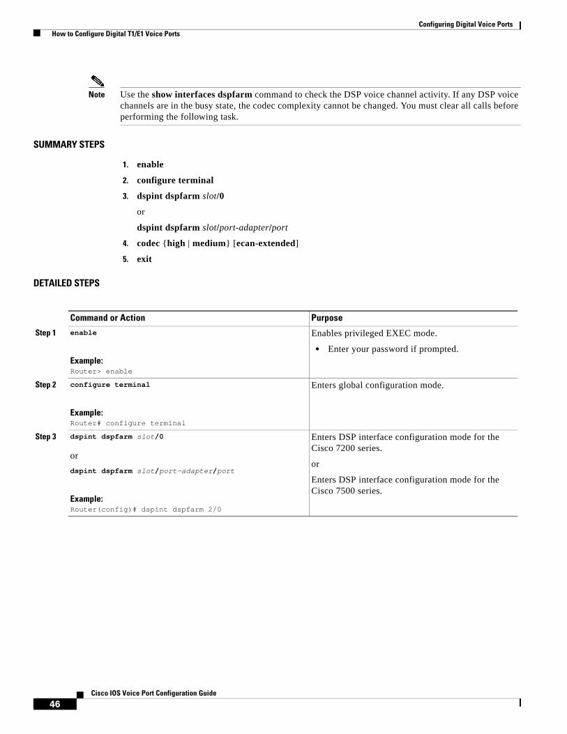
Configuring Digital Voice Ports How to Configure Digital T1/E1 Voice Ports
46Cisco IOS Voice Port Configuration Guide
Note Use the show interfaces dspfarm command to check the DSP voice channel activity. If any DSP voice channels are in the busy state, the codec complexity cannot be changed. You must clear all calls before performing the following task.
SUMMARY STEPS
1. enable
2. configure terminal
3. dspint dspfarm slot/0
or
dspint dspfarm slot/port-adapter/port
4. codec {high | medium} [ecan-extended]
5. exit
DETAILED STEPS
Command or Action Purpose
Step 1 enable
Example:Router> enable
Enables privileged EXEC mode.
• Enter your password if prompted.
Step 2 configure terminal
Example:Router# configure terminal
Enters global configuration mode.
Step 3 dspint dspfarm slot/0
or
dspint dspfarm slot/port-adapter/port
Example:Router(config)# dspint dspfarm 2/0
Enters DSP interface configuration mode for the Cisco 7200 series.
or
Enters DSP interface configuration mode for the Cisco 7500 series.

Configuring Digital Voice Ports How to Configure Digital T1/E1 Voice Ports
47Cisco IOS Voice Port Configuration Guide
Cisco 7200 Series
On the Cisco 7200 series, the PA-MCX-2TE1 port adapter (PA) card can be used for making voice calls. This PA does not have any DSPs but uses the DSP resources of the PA-VXC-2TE1+ card present in another slot. If the PA-MCX card is used, codec complexity is configured for PA-VXC, while all other echo cancellation configurations are done for PA-MCX.
The PA-MCX card borrows the DSP resources from the PA-VXC, PA-VXB, or PA-VXA card. If one of the PA-VXC, PA-VXB, or PA-VXA cards has extended echo cancellation configured on the DSP interface, extended echo cancellation is enabled for the PA-MCX card. It is recommended that you have the same codec complexity and echo cancellation configuration on all the PA-VXC, PA-VXB, or PA-VXA cards in the router.
Cisco AS5300
Codec support on the Cisco AS5300 is determined by the capability list on the voice feature card, which defines the set of codecs that can be negotiated for a voice call. The capability list is created and populated when VCWare is unbundled and DSPWare is added to VFC flash memory. The capability list does not indicate codec preference; it simply reports the codecs that are available. The session application decides which codec to use. Codec support is configured on dial peers rather than on voice ports; refer to the Dial Peer Configuration on Voice Gateway Routers document.
Cisco AS5800
Codec support is selected on Cisco AS5800 access servers during dial peer configuration. Refer to the Dial Peer Configuration on Voice Gateway Routers document.
Configuring Controller Settings for Digital T1/E1 Voice PortsThe controller configuration for digital T1/E1 voice ports must match the line characteristics of the telephony network connection so that voice and signaling can be transferred between them and so that logical voice ports, or DS0 groups, may be established.
Step 4 codec {high | medium} [ecan-extended]
Example:Router(config-dspfarm)# codec medium ecan-extended
Sets the codec complexity.
• The optional ecan-extended keyword selects the G.168 extended echo canceller. This keyword is supported only in Cisco IOS Release 12.2(13)T. For more information, see the “How to Configure the Extended G.168 Echo Canceller” section.
• This command affects the choice of codecs available when the codec command is used in dial-peer configuration mode.
Step 5 exit
Example:Router(config-dspfarm)# exit
Exits to global configuration mode.
Command or Action Purpose

Configuring Digital Voice Ports How to Configure Digital T1/E1 Voice Ports
48Cisco IOS Voice Port Configuration Guide
Figure 1 shows how a ds0-group command gathers some of the DS0 time slots from a T1 line into a group that becomes a single logical voice port that can later be addressed as a single entity in voice port configurations. Other DS0 groups for voice can be created from the remaining time slots shown in the figure, or the time slots can be used for data or serial pass-through.
Note All controller commands shown in Figure 1, other than ds0-group, apply to all time slots in the T1 line.
Figure 1 T1 Controller Configuration on Cisco 2600 or Cisco 3600 Series Routers
Voice port controller configuration includes setting the parameters described in the following sections:
• Framing Formats on Digital T1/E1 Voice Ports, page 48
• Clock Sources on Digital T1/E1 Voice Ports, page 49
• Network Clock Timing, page 52
• Line Coding on Digital T1/E1 Voice Ports, page 54
• DS0 Groups on Digital T1/E1 Voice Ports, page 54
Another controller command that might be needed, cablelength, is discussed in the Cisco IOS Interface and Hardware Component Command Reference.
Framing Formats on Digital T1/E1 Voice Ports
The framing format parameter describes the way that bits are robbed from specific frames to be used for signaling purposes. The controller must be configured to use the same framing format as the line from the PBX or CO that connects to the voice port you are configuring.
V V
Network module slot 1VWIC slot 0
T1
3776
0
controller t1 1/0framing esfclock source linelinecode b8zs
Configures T1controller 1/0
Creates DS0 group, or logical voice port, 1/0:1 by grouping 12 time slots together
ds0-group 1 timeslots 1-12 type e&m-wink-start
Configuring Digital Voice Ports How to Configure Digital T1/E1 Voice Ports
49Cisco IOS Voice Port Configuration Guide
Digital T1 lines use SF or ESF framing formats. SF provides two-state, continuous supervision signaling, in which bit values of 0 are used to represent on-hook and bit values of 1 are used to represent off-hook. ESF robs four bits instead of two, yet has little impact on voice quality. ESF is required for 64-kbps operation on DS0 and is recommended for PRI configurations.
E1 lines can be configured for CRC4 or no cyclic redundancy check, with an optional argument for E1 lines in Australia.
Clock Sources on Digital T1/E1 Voice Ports
Digital T1/E1 interfaces use timers called clocks to ensure that voice packets are delivered and assembled properly. All interfaces handling the same packets must be configured to use the same source of timing so that packets are not lost or delivered late. The timing source that is configured can be external (from the line) or internal to the router’s digital interface.
If the timing source is internal, timing derives from the onboard phase-lock loop (PLL) chip in the digital voice interface. If the timing source is line (external), then timing derives from the PBX or PSTN CO to which the voice port is connected. It is generally preferable to derive timing from the PSTN becauseits clocks are maintained at an extremely accurate level. This is the default setting for the clocks. When two or more controllers are configured, one should be designated as the primary clock source; it will drive the other controllers.
The line keyword specifies that the clock source is derived from the active line rather than from the free-running internal clock. The following rules apply to clock sourcing on the controller ports:
• When both ports are set to line clocking with no primary specification, port 0 is the default primary clock source and port 1 is the default secondary clock source.
• When both ports are set to line and one port is set as the primary clock source, the other port is by default the backup or secondary source and is loop-timed.
• If one port is set to clock source line or clock source line primary and the other is set to clock source internal, the internal port recovers clock from the clock source line port if the clock source line port is up. If it is down, then the internal port generates its own clock.
• If both ports are set to clock source internal, there is only one clock source: internal.
This section describes the five basic timing scenarios that can occur when a digital voice port is connected to a PBX or CO. In all the examples that follow, the PSTN (or CO) and the PBX are interchangeable for purposes of providing or receiving clocking.
• Single voice port providing clocking—In this scenario, the digital voice hardware is the clock source for the connected device, as shown in Figure 2. The PLL generates the clock internally and drives the clocking on the line. Generally, this method is useful only when connecting to a PBX, key system, or channel bank. A Cisco VoIP gateway rarely provides clocking to the CO because CO clocking is much more reliable. The following configuration sets up this clocking method for a digital E1 voice port:
controller E1 1/0 framing crc4 linecoding hdb3 clock source internal ds0-group timeslots 1-15 type e&m-wink-start

Configuring Digital Voice Ports How to Configure Digital T1/E1 Voice Ports
50Cisco IOS Voice Port Configuration Guide
Figure 2 Single Voice Port Providing Clocking
• Single voice port receiving internal clocking—In this scenario, the digital voice hardware receives clocking from the connected device (CO telephony switch or PBX) (see Figure 3). The PLL clocking is driven by the clock reference on the receive (Rx) side of the digital line connection.
Figure 3 Single E1 Port Receiving Clocking from the Line
The following configuration sets up this clocking method:
controller T1 1/0 framing esf linecoding ami clock source line ds0-group timeslots 1-12 type e&m-wink-start
• Dual voice ports receiving clocking from the Line—In this scenario, the digital voice port has two reference clocks, one from the PBX and another from the CO, as shown in Figure 4.
Figure 4 Dual E1 Ports Receiving Clocking from the Line
Because the PLL can derive clocking from only one source, this case is more complex than the two preceding examples. Before looking at the details, consider the following as they pertain to the clocking method:
– Looped-time clocking—The voice port takes the clock received on its Rx (receive) pair and regenerates it on its Tx (transmit) pair. While the port receives clocking, the port is not driving the PLL on the card but is “spoofing” (that is, fooling) the port so that the connected device has a viable clock and does not see slips (that is, loss of data bits). PBXs are not designed to accept slips on a T1 or E1 line, and such slips cause a PBX to drop the link into failure mode. While in looped-time mode, the router often sees slips, but because these are controlled slips, they usually do not force failures of the router’s voice port.
– Slips—These messages indicate that the voice port is receiving clock information that is out of phase (out of synchronization). Because the router has only a single PLL, it can experience controlled slips while it receives clocking from two different time sources. The router can usually handle controlled slips because its single-PLL architecture anticipates them.
E1 0
PBXClock 2691
9
E1 0Clock
2692
0
PSTN
E1 0
E1 1
Looped time
Clock
Clock
2692
1
PSTN
PBX

Configuring Digital Voice Ports How to Configure Digital T1/E1 Voice Ports
51Cisco IOS Voice Port Configuration Guide
Note Physical layer issues, such as bad cabling or faulty clocking references, can cause slips. Eliminate these slips by addressing the physical layer or clock reference problems.
In the dual voice ports receiving clocking from the line scenario, the PLL derives clocking from the CO and puts the voice port connected to the PBX into looped-time mode. This is usually the best method because the CO provides an excellent clock source (and the PLL usually requires that the CO provide that source) and a PBX usually must receive clocking from the other voice port.
The following configuration sets up this clocking method (controller E1 1/0 is connected to the CO; controller E1 1/1 is connected to the PBX:
controller E1 1/0 framing crc4 linecoding hdb3 clock source line primary ds0-group timeslots 1-15 type e&m-wink-start!controller E1 1/1 framing crc4 linecoding hdb3 clock source line ds0-group timeslots 1-15 type e&m-wink-start
The clock source line primary command tells the router to use this voice port to drive the PLL. All other voice ports configured as clock source line are then put into an implicit loop-timed mode. If the primary voice port fails or goes down, the other voice port instead receives the clock that drives the PLL. In this configuration, port 1/1 might see controlled slips, but these should not force it down. This method prevents the PBX from seeing slips.
Note When two T1/E1 lines terminate on a two-port interface card, such as the VWIC-2MFT, and both controllers are set for line clocking but the lines are not within clocking tolerance of one another, one of the controllers is likely to experience slips. To prevent slips, ensure that the two T1 or E1 lines are within clocking tolerance of one another, even if the lines are from different providers.
• Dual voice ports (one receives clocking and one provides clocking)—In this scenario, the digital voice hardware receives clocking for the PLL from E1 0 and uses this clock as a reference to clock E1 1 (see Figure 5). If controller E1 0 fails, the PLL internally generates the clock reference to drive E1 1.
Figure 5 Dual E1 Ports—One Receiving and One Providing Clocking
The following configuration sets up this clocking method:
controller E1 1/0 framing crc4 linecoding hdb3
E1 0
E1 1 Clock
Clock
2692
2
PSTN
PBX

Configuring Digital Voice Ports How to Configure Digital T1/E1 Voice Ports
52Cisco IOS Voice Port Configuration Guide
clock source line ds0-group timeslots 1-15 type e&m-wink-start!controller E1 1/1 framing crc4 linecoding hdb3 clock source internal ds0-group timeslots 1-15 type e&m-wink-start
• Dual voice ports (router provides both clocks)—In this scenario, the router generates the clock for the PLL and, therefore, for both voice ports (see Figure 6).
Figure 6 Dual E1 Ports—Both Clocks from the Router
The following configuration sets up this clocking method:
controller E1 1/0 framing crc4 linecoding hdb3 clock source internal ds0-group timeslots 1-15 type e&m-wink-start!controller E1 1/1 framing esf linecoding b8zs clock source internal ds0-group timeslots 1-15 type e&m-wink-start
Network Clock Timing
Voice systems that pass digitized (pulse code modulation or PCM) speech have always relied on the clocking signal being embedded in the received bit stream. This reliance allows connected devices to recover the clock signal from the bit stream, and then use this recovered clock signal to ensure that data on different channels keep the same timing relationship with other channels.
If a common clock source is not used between devices, the binary values in the bit streams may be misinterpreted because the device samples the signal at the wrong moment. As an example, if the local timing of a receiving device is using a slightly shorter time period than the timing of the sending device, a string of eight continuous binary 1s may be interpreted as nine continuous 1s. If this data is then re-sent to further downstream devices that used varying timing references, the error could be compounded. By ensuring that each device in the network uses the same clocking signal, you can ensure the integrity of the traffic.
If timing between devices is not maintained, a condition known as clock slip can occur. Clock slip is the repetition or deletion of a block of bits in a synchronous bit stream due to a discrepancy in the read and write rates at a buffer.
Slips are caused by the inability of an equipment buffer store (or other mechanisms) to accommodate differences between the phases or frequencies of the incoming and outgoing signals in cases where the timing of the outgoing signal is not derived from that of the incoming signal.
E1 1/0
E1 1/1
Clock
2692
3Clock
PSTN
PBX
Configuring Digital Voice Ports How to Configure Digital T1/E1 Voice Ports
53Cisco IOS Voice Port Configuration Guide
A T1 or E1 interface sends traffic inside repeating bit patterns called frames. Each frame is a fixed number of bits, allowing the device to see the start and end of a frame. The receiving device also knows exactly when to expect the end of a frame simply by counting the appropriate number of bits that have come in. Therefore, if the timing between the sending and receiving device is not the same, the receiving device may sample the bit stream at the wrong moment, resulting in an incorrect value being returned.
Even though Cisco IOS software can be used to control the clocking on these platforms, the default clocking mode is effectively free running, meaning that the received clock signal from an interface is not connected to the backplane of the router and used for internal synchronization between the rest of the router and its interfaces. The router will use its internal clock source to pass traffic across the backplane and other interfaces.
For data applications, this clocking generally does not present a problem as a packet is buffered in internal memory and is then copied to the transmit buffer of the destination interface. The reading and writing of packets to memory effectively removes the need for any clock synchronization between ports.
Digital voice ports have a different issue. It would appear that unless otherwise configured, Cisco IOS software uses the backplane (or internal) clocking to control the reading and writing of data to the DSPs. If a PCM stream comes in on a digital voice port, it will be using the external clocking for the received bit stream. However, this bit stream will not necessarily be using the same reference as the router backplane, meaning the DSPs may misinterpret the data coming in from the controller.
This clocking mismatch is seen on the router’s E1 or T1 controller as a clock slip—the router is using its internal clock source to send the traffic out the interface but the traffic coming in to the interface is using a completely different clock reference. Eventually, the difference in the timing relationship between the transmit and receive signal becomes so great that the controller registers a slip in the received frame.
To eliminate the problem, change the default clocking behavior through Cisco IOS configuration commands. It is absolutely critical to set up the clocking commands properly.
Even though these commands are optional, we strongly recommend you enter them as part of your configuration to ensure proper network clock synchronization:
network-clock-participate [slot slot-number | wic wic-slot | aim aim-slot-number]network-clock-select priority {bri | t1 | e1} slot/port
The network-clock-participate command allows the router to use the clock from the line via the specified slot/WIC/AIM and synchronize the onboard clock to the same reference.
If multiple VWICS are installed, the commands must be repeated for each installed card. The system clocking can be confirmed using the show network clocks command.
Caution If you are configuring a Cisco 2600 XM voice gateway with an NM-HDV2 or NM-HD-2VE installed in slot 1, do not use the network-clock-participate slot 1 command in the configuration. In this particular hardware scenario, the network-clock-participate slot 1 command is not necessary.
If the network-clock-participate slot 1 command is configured, voice and data connectivity on interfaces terminating on the NM-HDV2 or NM-HD-2VE network module may fail to operate properly. Data connectivity to peer devices may not be possible, and even loopback plug tests to the serial interface spawned via a channel group configured on the local T1/E1 controller will fail. Voice groups such as CAS DS0 groups and ISDN PRI groups may fail to signal properly. The T1/E1 controller may accumulate large amounts of timing slips and Path Code Violations (PCVs) and Line Code Violations (LCVs).
Configuring Digital Voice Ports How to Configure Digital T1/E1 Voice Ports
54Cisco IOS Voice Port Configuration Guide
Line Coding on Digital T1/E1 Voice Ports
Digital T1/E1 interfaces require that line encoding be configured to match that of the PBX or CO that is being connected to the voice port. Line encoding defines the type of framing used on the line.
T1 line encoding methods include AMI and B8ZS. AMI is used on older T1 circuits and references signal transitions with a binary 1, or “mark.” B8ZS, a more reliable method, is more popular and is recommended for PRI configurations as well. B8ZS encodes a sequence of eight zeros in a unique binary sequence to detect line-coding violations.
Supported E1 line encoding methods are AMI and HDB3, which is a form of zero-suppression line coding.
DS0 Groups on Digital T1/E1 Voice Ports
For digital voice ports, a single command, ds0-group, performs the following functions:
• Defines the T1/E1 channels for compressed voice calls.
• Automatically creates a logical voice port.
The numbering for the logical voice port created as a result of this command is controller:ds0-group-number, where controller is defined as the platform-specific address for a particular controller. On a Cisco 3640 router, for example, ds0-group 1 timeslots 1-24 type e&m-wink automatically creates the voice port 1/0:1 when issued in the configuration mode for controller 1/0. On a Cisco MC3810 universal concentrator, when you are in the configuration mode for controller 0, the ds0-group 1 timeslots 1-24 type e&m-wink command creates logical voice port 0:1.
To map individual DS0s, define additional DS0 groups under the T1/E1 controller, specifying different time slots. Defining additional DS0 groups also creates individual DS0 voice ports.
• Defines the emulated analog signaling method that the router uses to connect to the PBX or PSTN.
Most digital T1/E1 connections used for switch-to-switch (or switch-to-router) trunks are E&M connections, but FXS and FXO connections are also supported. These are normally used to provide emulated-OPX (Off-Premises eXtension) from a PBX to remote stations. FXO ports connect to FXS ports. The FXO or FXS connection between the router and switch (CO or PBX) must use matching signaling, or calls cannot connect properly. Either ground-start or loop-start signaling is appropriate for these connections. Ground-start provides better disconnect supervision to detect when a remote user has hung up the telephone, but ground-start is not available on all PBXs.
Digital ground start differs from digital E&M because the A and B bits do not track each other as they do in digital E&M signaling (that is, A is not necessarily equal to B). When the CO delivers a call, it seizes a channel (goes off-hook) by setting the A bit to 0. The CO equipment also simulates ringing by toggling the B bit. The terminating equipment goes off-hook when it is ready to answer the call. Digits are usually not delivered for incoming calls.
E&M connections can use one of three different signaling types to acknowledge on-hook and off-hook states: wink start, immediate-start, and delay-start. E&M wink start is usually preferred, but not all COs and PBXs can handle wink-start signaling. The E&M connection between the router and switch (CO or PBX) must match the CO or PBX E&M signaling type, or calls cannot be connected properly.
E&M signaling is normally used for trunks. It is normally the only way that a CO switch can provide two-way dialing with DID. In all the E&M protocols, off-hook is indicated by A=B=1 and on-hook is indicated by A=B=0 (robbed-bit signaling). If dial pulse dialing is used, the A and B bits are pulsed to indicate the addressing digits. The are several further important subclasses of E&M robbed-bit signaling:

Configuring Digital Voice Ports How to Configure Digital T1/E1 Voice Ports
55Cisco IOS Voice Port Configuration Guide
– E&M wink-start—Feature Group B
In the original wink start handshaking protocol, the terminating side responds to an off-hook from the originating side with a short wink (transition from on-hook to off-hook and back again). This wink tells the originating side that the terminating side is ready to receive addressing digits. After receiving addressing digits, the terminating side then goes off-hook for the duration of the call. The originating endpoint maintains off-hook for the duration of the call.
– E&M wink-start—Feature Group D
In Feature Group D wink-start with wink acknowledge handshaking protocol, the terminating side responds to an off-hook from the originating side with a short wink (transition from on-hook to off-hook and back again) just as in the original wink-start. This wink tells the originating side that the terminating side is ready to receive addressing digits. After receiving addressing digits, the terminating side provides another wink (called an acknowledgment wink) that tells the originating side that the terminating side has received the dialed digits. The terminating side then goes off-hook to indicate connection. This last indication can be due to the ultimate called endpoint’s having answered. The originating endpoint maintains an off-hook condition for the duration of the call.
– E&M immediate-start
In the immediate-start protocol, the originating side does not wait for a wink before sending addressing information. After receiving addressing digits, the terminating side then goes off-hook for the duration of the call. The originating endpoint maintains off-hook for the duration of the call.
Note Feature Group D is supported on Cisco AS5300 platforms, and on Cisco 2600, Cisco 3600, and Cisco 7200 series with digital T1 packet voice trunk network modules. Feature Group D is not supported on E1 or analog voice ports.
To configure controller settings for digital T1/E1 voice ports, use the following commands:
SUMMARY STEPS
1. enable
2. configure terminal
3. card type {t1 | e1} slotorcard type {t1 | e1} slot/port
4. controller {t1 | e1} slot/portorcontroller {t1 | e1} numberorcontroller {t1 | e1} shelf/slot/port
5. framing {sf | esf}orframing {crc4 | no-crc4} [australia]
6. clock source {line [primary | secondary] | internal}
7. linecode {ami | b8zs}orlinecode {ami | hdb3}

Configuring Digital Voice Ports How to Configure Digital T1/E1 Voice Ports
56Cisco IOS Voice Port Configuration Guide
8. ds0-group ds0-group-number timeslots timeslot-list type {e&m-delay-dial | e&m-fgd | e&m-immediate-start | e&m-wink-start | ext-sig | fgd-eana | fxo-ground-start | fxo-loop-start | fxs-ground-start | fxs-loop-start}
9. no shutdown
DETAILED STEPS
Command Purpose
Step 1 enable
Example:Router> enable
Enables privileged EXEC mode.
• Enter your password if prompted.
Step 2 configure terminal
Example:Router# configure terminal
Enters global configuration mode.
Step 3 card type {t1 | e1} slot
Example:Router(config)# card type t1 0
Defines the card as T1 or E1 and identifies the location.
Step 4 controller {t1 | e1} slot/port
or
controller {t1 | e1} number
or
controller {t1 | e1} shelf/slot/port
Example:Router(config)# controller t1 1/0
or
Example:Router(config)# controller t1 1
or
Example:Router(config)# controller t1 1/0/0
Enters controller configuration mode and specifies either T1 or E1 for the line.
• For the Cisco 2600, Cisco 3600 series, Cisco MC3810, and Cisco 7200 series, identifies the slot and port.
• For the Cisco AS5300, identifies the port number.
• For the Cisco AS5800 and Cisco 7500 series, identifies the shelf, slot, and port number.

Configuring Digital Voice Ports How to Configure Digital T1/E1 Voice Ports
57Cisco IOS Voice Port Configuration Guide
Configuring Basic Voice Port Parameters for Digital T1/E1 Voice Ports
For FXO and FXS connections the default voice-port parameter values are often adequate. However, for E&M connections, it is important to match the characteristics of your PBX, so voice port parameters may need to be reconfigured from their defaults.
Step 5 framing {sf | esf}
or
framing {crc4 | no-crc4} [australia]
Example:Router(config-controller)# framing esf
or
Example:Router(config-controller)# framing crc4
Selects frame type for T1 or E1 line.
• For T1, the frame type can be sf or esf. Default for T1 is sf.
• For E!, the frame type can be crc4 or no crc4 or australia. Default for E1 is crc4.
Step 6 clock source {line [primary | secondary] | internal}
Example:Router(config-controller)# clock source line primary
Configures the clock source.
• Default is line.
• For more information about clock sources, see the “Clock Sources on Digital T1/E1 Voice Ports” section on page 49.
Step 7 linecode {ami | b8zs}
or
linecode {ami | hdb3}
Example:Router(config-controller)# linecode b8zs
or
Example:Router(config-controller)# linecode hdb3
Specifies the line encoding to use for T1 or E1 line.
• For T1, the line encoding can be ami or b8zs. Default for T1 is ami.
• For E1, the line encoding can be ami or hdb3. Default for E1 is hdb3.
Step 8 ds0-group ds0-group-number timeslots timeslot-list type {e&m-delay-dial | e&m-fgd | e&m-immediate-start |e&m-wink-start | ext-sig | fgd-eana | fxo-ground-start | fxo-loop-start | fxs-ground-start | fxs-loop-start}
Example:Router(config-controller)# ds0-group 30 timeslots 0 type e&m-immediate-start
Defines the T1 channels for use by compressed voice calls and the signaling method that the router uses to connect to the PBX or CO.
Note This step shows the basic syntax and signaling types available with the ds0-group command. For the complete syntax, refer to the Cisco IOS Voice Command Reference.
Step 9 no shutdown
Example:Router(config-controller)# no shutdown
Activates the controller.
Command Purpose

Configuring Digital Voice Ports How to Configure Digital T1/E1 Voice Ports
58Cisco IOS Voice Port Configuration Guide
Each voice port that you address in digital voice port configuration is one of the logical voice ports that you created with the ds0-group command.
Companding (from compression and expansion), used in Step 6 of the following table, is the part of the PCM process in which analog signal values are logically rounded to discrete scale-step values on a nonlinear scale. The decimal step number is then coded in its binary equivalent prior to transmission. The process is reversed at the receiving terminal using the same nonlinear scale.
Note The commands, keywords, and arguments that you are able to use may differ slightly from those presented here, based on your platform, Cisco IOS release, and configuration. When in doubt, use Cisco IOS command help to determine the syntax choices that are available.
To configure basic parameters for digital T1/E1 voice ports, use the following commands:
SUMMARY STEPS
1. enable
2. configure terminal
3. voice-port portorvoice-port slot/port:ds0-group-numberorvoice-port slot/port-adapter:ds0-group-numberorvoice-port slot/port-adapter/slot:ds0-group-numberorvoice-port controller:{ds0-group-number | D}orvoice-port slot/controller:{ds0-group-number | D}orvoice-port shelf/slot/port:ds0-group-number
4. type {1 | 2 | 3 | 5}
5. cptone locale
6. compand-type {u-law | a-law}
7. ring frequency {25 | 50}
8. ring number number
9. ring cadence {[pattern01 | pattern02 | pattern03 | pattern04 | pattern05 | pattern06 | pattern07 | pattern08 | pattern09 | pattern10 | pattern11 | pattern12] [define pulse interval]}
10. description string
11. no shutdown
Configuring Digital Voice Ports How to Configure Digital T1/E1 Voice Ports
59Cisco IOS Voice Port Configuration Guide
DETAILED STEPS
Command Purpose
Step 1 enable
Example:Router> enable
Enables privileged EXEC mode.
• Enter your password if prompted.
Step 2 configure terminal
Example:Router# configure terminal
Enters global configuration mode.
Step 3 voice-port portorvoice-port slot/port:ds0-group-numberorvoice-port slot/port-adapter:ds0-group-number
or
voice-port slot/port-adapter/slot:ds0-group-number
or
voice-port controller:{ds0-group-number | D}
or
voice-port slot/controller:{ds0-group-number | D}
or
voice-port shelf/slot/port:ds0-group-number
Example:Router(config)# voice-port 1:0
or
Example:Router(config)# voice-port 1/1:0
or
Example:Router(config)# voice-port 1/1/1:1
or
Example:Router(config)# voice-port 1:1
or
Example:Router(config)# voice-port 1/0 D
or
Example:Router(config)# voice-port 1/2/0:1
Enters voice-port configuration mode and identifies the port to be configured.
• For the Cisco 880 series, specify the port number.
• For the Cisco 2600, Cisco 3600, and Cisco 3700 series, specify the slot, port, and DS0 group number.
• For the Cisco 7200 series, specify the slot, port adapter,and DS0 group number.
• For the Cisco 7500 series, specify the slot, port adapter, slot, and DS0 group number.
• For the Cisco AS5300, specify the controller and DS0 group number or the keyword D.
• For the Cisco AS5350, Cisco AS5400, and Cisco AS5850 universal gateways, specify the slot, controller, and DS0 group number or the keyword D.
• For the Cisco AS5800, specify the shelf, slot, port, and DS0 group number.

Configuring Digital Voice Ports How to Configure Digital T1/E1 Voice Ports
60Cisco IOS Voice Port Configuration Guide
Step 4 type {1 | 2 | 3 | 5}
Example:Router(config-voiceport)# type 1
(E&M only) Specifies the type of E&M interface to which this voice port is connected. See Table 3 in the Vo ice Port Configuration Overview chapter for an explanation of E&M types.
• Default is 1.
Step 5 cptone locale
Example:Router(config-voiceport)# cptone us
Selects a two-letter locale keyword for the voice call progress tones and other locale-specific parameters to be used on this voice port. Voice call progress tones include dial tone, busy tone, and ringback tone, which vary with geographical region.
• Other parameters include ring cadence and compand type. Cisco routers comply with the ISO3166 locale name standards; to see valid choices, enter a question mark (?) following the cptone command.
• Default is us.
Step 6 compand-type {u-law | a-law}
Example:Router(config-voiceport)# compand-type u-law
(Cisco 2600 and Cisco 3600 series routers.) Specifies the companding standard used. This command is used in cases when the DSP is not used, such as local cross-connects, and overwrites the compand-type value set by the cptone command.
• The default for E1 is a-law.
• The default for T1 is u-law.
Note If you have a Cisco 3660 router, the compand-type a-law command must be configured on the analog ports only. The Cisco 2660, 3620, and 3640 routers do not require the compand-type a-law command configured. However, if you request a list of commands, the compand-type a-law command will display.
Step 7 ring frequency {25 | 50}
Example:Router(config-voiceport)# ring frequency 50
(FXS only) Selects the ring frequency, in hertz, used on the FXS interface. This number must match the connected telephony equipment, and can be country-dependent. If the ring frequency is not set properly, the attached telephony device may not ring or it may buzz.
• Default is 25.
Step 8 ring number number
Example:Router(config-voiceport)# ring number 1
(FXO only) Specifies the maximum number of rings to be detected before an incoming call is answered by the router.
• Default is 1.
Command Purpose
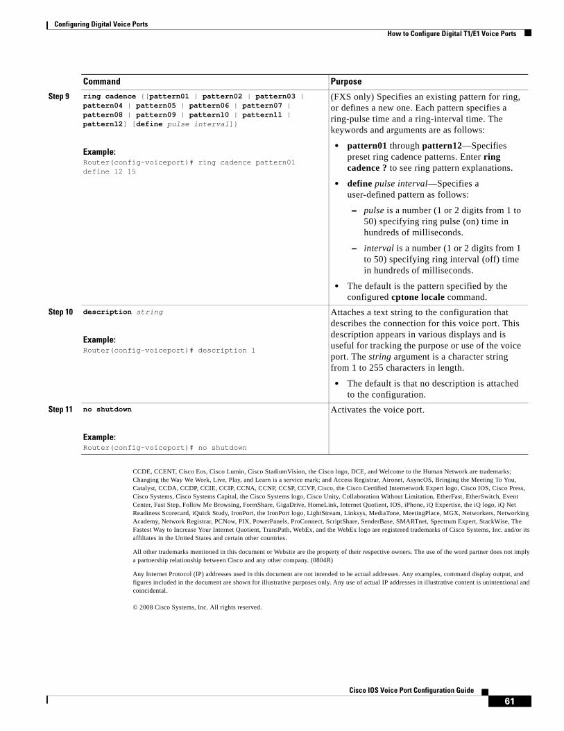
Configuring Digital Voice Ports How to Configure Digital T1/E1 Voice Ports
61Cisco IOS Voice Port Configuration Guide
CCDE, CCENT, Cisco Eos, Cisco Lumin, Cisco StadiumVision, the Cisco logo, DCE, and Welcome to the Human Network are trademarks; Changing the Way We Work, Live, Play, and Learn is a service mark; and Access Registrar, Aironet, AsyncOS, Bringing the Meeting To You, Catalyst, CCDA, CCDP, CCIE, CCIP, CCNA, CCNP, CCSP, CCVP, Cisco, the Cisco Certified Internetwork Expert logo, Cisco IOS, Cisco Press, Cisco Systems, Cisco Systems Capital, the Cisco Systems logo, Cisco Unity, Collaboration Without Limitation, EtherFast, EtherSwitch, Event Center, Fast Step, Follow Me Browsing, FormShare, GigaDrive, HomeLink, Internet Quotient, IOS, iPhone, iQ Expertise, the iQ logo, iQ Net Readiness Scorecard, iQuick Study, IronPort, the IronPort logo, LightStream, Linksys, MediaTone, MeetingPlace, MGX, Networkers, Networking Academy, Network Registrar, PCNow, PIX, PowerPanels, ProConnect, ScriptShare, SenderBase, SMARTnet, Spectrum Expert, StackWise, The Fastest Way to Increase Your Internet Quotient, TransPath, WebEx, and the WebEx logo are registered trademarks of Cisco Systems, Inc. and/or its affiliates in the United States and certain other countries.
All other trademarks mentioned in this document or Website are the property of their respective owners. The use of the word partner does not imply a partnership relationship between Cisco and any other company. (0804R)
Any Internet Protocol (IP) addresses used in this document are not intended to be actual addresses. Any examples, command display output, and figures included in the document are shown for illustrative purposes only. Any use of actual IP addresses in illustrative content is unintentional and coincidental.
© 2008 Cisco Systems, Inc. All rights reserved.
Step 9 ring cadence {[pattern01 | pattern02 | pattern03 | pattern04 | pattern05 | pattern06 | pattern07 | pattern08 | pattern09 | pattern10 | pattern11 | pattern12] [define pulse interval]}
Example:Router(config-voiceport)# ring cadence pattern01 define 12 15
(FXS only) Specifies an existing pattern for ring, or defines a new one. Each pattern specifies a ring-pulse time and a ring-interval time. The keywords and arguments are as follows:
• pattern01 through pattern12—Specifies preset ring cadence patterns. Enter ring cadence ? to see ring pattern explanations.
• define pulse interval—Specifies a user-defined pattern as follows:
– pulse is a number (1 or 2 digits from 1 to 50) specifying ring pulse (on) time in hundreds of milliseconds.
– interval is a number (1 or 2 digits from 1 to 50) specifying ring interval (off) time in hundreds of milliseconds.
• The default is the pattern specified by the configured cptone locale command.
Step 10 description string
Example:Router(config-voiceport)# description 1
Attaches a text string to the configuration that describes the connection for this voice port. This description appears in various displays and is useful for tracking the purpose or use of the voice port. The string argument is a character string from 1 to 255 characters in length.
• The default is that no description is attached to the configuration.
Step 11 no shutdown
Example:Router(config-voiceport)# no shutdown
Activates the voice port.
Command Purpose

Configuring Digital Voice Ports How to Configure Digital T1/E1 Voice Ports
62Cisco IOS Voice Port Configuration Guide
Americas Headquarters:Cisco Systems, Inc., 170 West Tasman Drive, San Jose, CA 95134-1706 USA
© 2008 Cisco Systems, Inc. All rights reserved.
Fine-Tuning Analog and Digital Voice Ports
The default parameter values for voice ports are usually sufficient for most networks. Depending on the specifics of your particular network, however, you may need to adjust certain parameters that are configured on voice ports. Collectively, these commands are referred to as voice port tuning commands.
Note The commands, keywords, and arguments that you are able to use may differ slightly from those presented here, based on your platform, Cisco IOS release, and configuration. When in doubt, use Cisco IOS command help to determine the syntax choices that are available.
Information About Fine-Tuning Analog and Digital Voice PortsThis section provides basic information about some the features that can be fine-tuned to improve the performance of your voice network:
• Channel Bank Support for T1/E1 Voice Ports—Provides support for the time-division multiplexing (TDM) cross-connect functionality between analog voice ports and digital DS0s on the same NM-HD-2VE using channel associated signaling (CAS).
• Auto Cut-Through—Allows you to connect to PBXs that do not provide an M-lead response.
• Modification of Bit Patterns for Digital Voice Ports—Enables commands for digital voice ports to modify sent or received bit patterns. Different versions of E&M use different ABCD signaling bits to represent idle and seize.
• ANI for Outbound Calling—Allows the automatic number identification (ANI) to be sent for outgoing calls on the Cisco AS5300 (if T1 CAS is configured with the Feature Group-D (FGD)—Exchange Access North American (FGD-EANA) signaling).
• Disconnect Supervision—Configures the router to recognize the type of signaling in use by the PBX or PSTN switch connected to the voice port. These methods include the following:
– Battery reversal disconnect
– Battery denial disconnect
– Supervisory tone disconnect (STD)
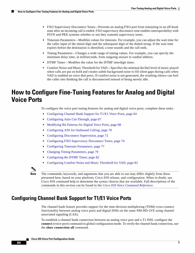
Fine-Tuning Analog and Digital Voice Ports How to Configure Fine-Tuning Features for Analog and Digital Voice Ports
64Cisco IOS Voice Port Configuration Guide
• FXO Supervisory Disconnect Tones—Prevents an analog FXO port from remaining in an off-hook state after an incoming call is ended. FXO supervisory disconnect tone enables interoperability with PSTN and PBX systems whether or not they transmit supervisory tones.
• Timeouts Parameters—Modifies values for timeouts. For example, you can adjust the wait time for the caller input of the initial digit and the subsequent digit of the dialed string. If the wait time expires before the destination is identified, a tone sounds and the call ends.
• Timing Parameters—Changes a wide range of timing values. For example, you can specify the minimum delay time, in milliseconds, from outgoing seizure to outdial address.
• DTMF Timer—Modifies the value for the DTMF interdigit timer.
• Comfort Noise and Music Threshold for VAD—Specifies the minimal decibel level of music played when calls are put on hold and creates subtle background noise to fill silent gaps during calls when VAD is enabled on voice dial peers. If comfort noise is not generated, the resulting silence can fool the caller into thinking the call is disconnected instead of being merely idle.
How to Configure Fine-Tuning Features for Analog and Digital Voice Ports
To configure the voice port tuning features for analog and digital voice ports, complete these tasks:
• Configuring Channel Bank Support for T1/E1 Voice Ports, page 64
• Configuring Auto Cut-Through, page 67
• Modifying Bit Patterns for Digital Voice Ports, page 68
• Configuring ANI for Outbound Calling, page 70
• Configuring Disconnect Supervision, page 72
• Configuring FXO Supervisory Disconnect Tones, page 74
• Configuring Timeouts Parameters, page 77
• Changing Timing Parameters, page 79
• Configuring the DTMF Timer, page 82
• Configuring Comfort Noise and Music Threshold for VAD, page 83
Note The commands, keywords, and arguments that you are able to use may differ slightly from those presented here, based on your platform, Cisco IOS release, and configuration. When in doubt, use Cisco IOS command help to determine the syntax choices that are available. Full descriptions of the commands in this section can be found in the Cisco IOS Voice Command Reference.
Configuring Channel Bank Support for T1/E1 Voice PortsThe channel bank feature provides support for the time-division multiplexing (TDM) cross-connect functionality between analog voice ports and digital DS0s on the same NM-HD-2VE using channel associated signaling (CAS).
To establish a channel bank connection between an analog voice port and a T1 DS0, configure the connect (voice-port) command in global configuration mode. To verify the channel bank connection, use the show connection all command.

Fine-Tuning Analog and Digital Voice Ports How to Configure Fine-Tuning Features for Analog and Digital Voice Ports
65Cisco IOS Voice Port Configuration Guide
Restrictions for Channel Bank Support
• The configuration for cross-connect must be on the same network module.
• A maximum of four Foreign Exchange Service (FXS) or Foreign Exchange Office (FXO) ports can be cross-connected to a T1 interface.
• A BRI-to-PRI cross-connect cannot be configured.
• Analog-to-BRI/PRI cross-connect cannot be configured; the only connection for analog is analog-to-T1/E1 CAS (ds0-group).
• The local-bypass command has no effect when cross-connect is configured. It is applicable only to calls that are hairpinned via POTS-to-POTS dial peers.
• The DS0 group must contain only one time slot. The signaling type of the DS0 group must match that of the analog voice port.
• If the channel bank feature is used for the T1 controller, the rest of the unused DS0 group cannot be used for fractional PRI signaling.
SUMMARY STEPS
1. enable
2. configure terminal
3. controller {t1 | e1} slot/port
4. ds0-group ds0-group-number timeslots timeslot-list type {e&m-delay-dial | e&m-fgd | e&m-immediate-start | e&m-wink-start | fxo-ground-start | fxo-loop-start | fxs-ground-start | fxs-loop-start}
5. exit
6. voice-port slot/port
7. operation {2-wire | 4-wire}
8. type {1 | 2 | 3 | 5}
9. signal {loop-start | ground-start}
or
signal {wink-start | immediate | delay-dial}
10. exit
11. connect connection-name voice-port voice-port-number {t1 | e1} controller-number ds0-group-number
12. exit
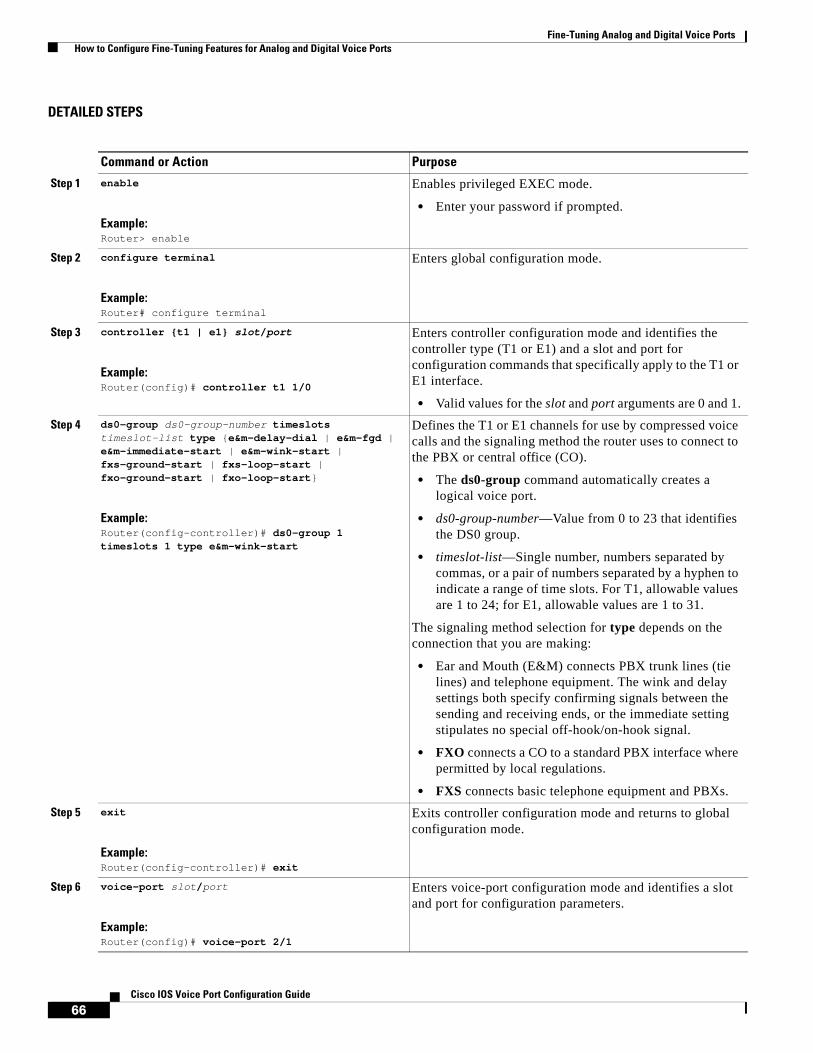
Fine-Tuning Analog and Digital Voice Ports How to Configure Fine-Tuning Features for Analog and Digital Voice Ports
66Cisco IOS Voice Port Configuration Guide
DETAILED STEPS
Command or Action Purpose
Step 1 enable
Example:Router> enable
Enables privileged EXEC mode.
• Enter your password if prompted.
Step 2 configure terminal
Example:Router# configure terminal
Enters global configuration mode.
Step 3 controller {t1 | e1} slot/port
Example:Router(config)# controller t1 1/0
Enters controller configuration mode and identifies the controller type (T1 or E1) and a slot and port for configuration commands that specifically apply to the T1 or E1 interface.
• Valid values for the slot and port arguments are 0 and 1.
Step 4 ds0-group ds0-group-number timeslots timeslot-list type {e&m-delay-dial | e&m-fgd | e&m-immediate-start | e&m-wink-start | fxs-ground-start | fxs-loop-start | fxo-ground-start | fxo-loop-start}
Example:Router(config-controller)# ds0-group 1 timeslots 1 type e&m-wink-start
Defines the T1 or E1 channels for use by compressed voice calls and the signaling method the router uses to connect to the PBX or central office (CO).
• The ds0-group command automatically creates a logical voice port.
• ds0-group-number—Value from 0 to 23 that identifies the DS0 group.
• timeslot-list—Single number, numbers separated by commas, or a pair of numbers separated by a hyphen to indicate a range of time slots. For T1, allowable values are 1 to 24; for E1, allowable values are 1 to 31.
The signaling method selection for type depends on the connection that you are making:
• Ear and Mouth (E&M) connects PBX trunk lines (tie lines) and telephone equipment. The wink and delay settings both specify confirming signals between the sending and receiving ends, or the immediate setting stipulates no special off-hook/on-hook signal.
• FXO connects a CO to a standard PBX interface where permitted by local regulations.
• FXS connects basic telephone equipment and PBXs.
Step 5 exit
Example:Router(config-controller)# exit
Exits controller configuration mode and returns to global configuration mode.
Step 6 voice-port slot/port
Example:Router(config)# voice-port 2/1
Enters voice-port configuration mode and identifies a slot and port for configuration parameters.

Fine-Tuning Analog and Digital Voice Ports How to Configure Fine-Tuning Features for Analog and Digital Voice Ports
67Cisco IOS Voice Port Configuration Guide
Configuring Auto Cut-ThroughThe auto-cut-through command allows you to connect to PBXs that do not provide an M-lead response. To configure auto-cut-through, complete the following task:
SUMMARY STEPS
1. enable
2. configure terminal
Step 7 operation {2-wire | 4-wire}
Example:Router(config-voiceport)# operation 4-wire
Selects a specific cabling scheme for E&M ports:
• This command is not applicable to FXS or FXO interfaces because they are, by definition, 2-wire interfaces.
• Using this command on a voice port changes the operation of both voice ports on a VPM card. The voice port must be shut down and then opened again for the new value to take effect.
Step 8 type {1 | 2 | 3 | 5}
Example:Router(config-voiceport)# type 2
Specifies the E&M interface type.
Step 9 signal {loop-start | ground-start}
or
signal {wink-start | immediate | delay-dial}
Example:Router(config-voiceport)# signal loop-start
or
Router(config-voiceport)# signal wink-start
Defines the signal type to be used.
Step 10 exit
Example:Router(config-voiceport)# exit
Exits voice-port configuration mode and returns to global configuration mode.
Step 11 connect connection-name voice-port voice-port-number {t1 | e1} controller-number ds0-group-number
Example:Router(config)# connect connect1 voice-port 1/1/0 t1 1/0 0
Creates a named connection between two voice ports associated with T1 or E1 interfaces where you have already defined the groups by using the ds0-group command.
Step 12 exit
Example:Router(config)# exit
Exits the current configuration session and returns to privileged EXEC mode.
Command or Action Purpose
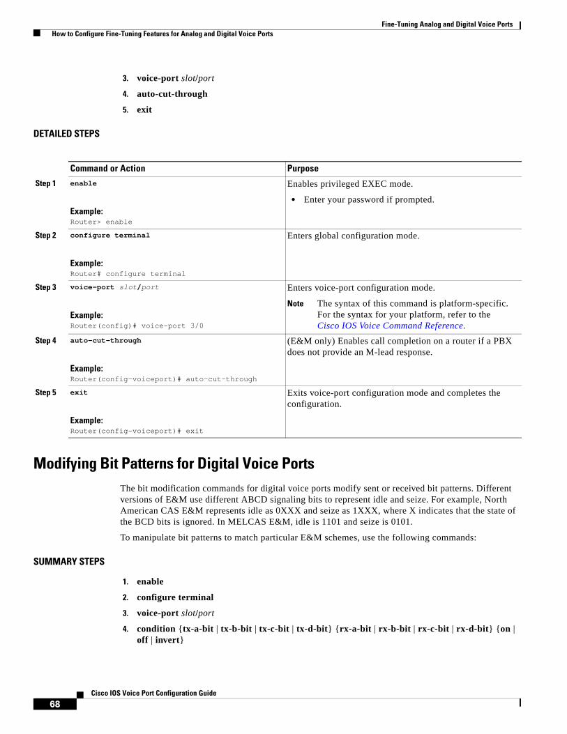
Fine-Tuning Analog and Digital Voice Ports How to Configure Fine-Tuning Features for Analog and Digital Voice Ports
68Cisco IOS Voice Port Configuration Guide
3. voice-port slot/port
4. auto-cut-through
5. exit
DETAILED STEPS
Modifying Bit Patterns for Digital Voice PortsThe bit modification commands for digital voice ports modify sent or received bit patterns. Different versions of E&M use different ABCD signaling bits to represent idle and seize. For example, North American CAS E&M represents idle as 0XXX and seize as 1XXX, where X indicates that the state of the BCD bits is ignored. In MELCAS E&M, idle is 1101 and seize is 0101.
To manipulate bit patterns to match particular E&M schemes, use the following commands:
SUMMARY STEPS
1. enable
2. configure terminal
3. voice-port slot/port
4. condition {tx-a-bit | tx-b-bit | tx-c-bit | tx-d-bit} {rx-a-bit | rx-b-bit | rx-c-bit | rx-d-bit} {on | off | invert}
Command or Action Purpose
Step 1 enable
Example:Router> enable
Enables privileged EXEC mode.
• Enter your password if prompted.
Step 2 configure terminal
Example:Router# configure terminal
Enters global configuration mode.
Step 3 voice-port slot/port
Example:Router(config)# voice-port 3/0
Enters voice-port configuration mode.
Note The syntax of this command is platform-specific. For the syntax for your platform, refer to the Cisco IOS Voice Command Reference.
Step 4 auto-cut-through
Example:Router(config-voiceport)# auto-cut-through
(E&M only) Enables call completion on a router if a PBX does not provide an M-lead response.
Step 5 exit
Example:Router(config-voiceport)# exit
Exits voice-port configuration mode and completes the configuration.
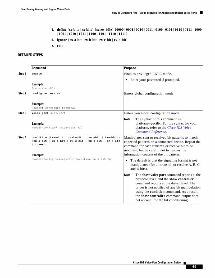
Fine-Tuning Analog and Digital Voice Ports How to Configure Fine-Tuning Features for Analog and Digital Voice Ports
69Cisco IOS Voice Port Configuration Guide
5. define {tx-bits | rx-bits} {seize | idle} {0000 | 0001 | 0010 | 0011 | 0100 | 0101 | 0110 | 0111 | 1000 | 1001 | 1010 | 1011 | 1100 | 1101 | 1110 | 1111}
6. ignore {rx-a-bit | rx-b-bit | rx-c-bit | rx-d-bit}
7. exit
DETAILED STEPS
Command Purpose
Step 1 enable
Example:Router> enable
Enables privileged EXEC mode.
• Enter your password if prompted.
Step 2 configure terminal
Example:Router# configure terminal
Enters global configuration mode.
Step 3 voice-port slot/port
Example:Router(config)# voice-port 3/0
Enters voice-port configuration mode.
Note The syntax of this command is platform-specific. For the syntax for your platform, refer to the Cisco IOS Voice Command Reference.
Step 4 condition {tx-a-bit | tx-b-bit | tx-c-bit | tx-d-bit} {rx-a-bit | rx-b-bit | rx-c-bit | rx-d-bit} {on | off | invert}
Example:Router(config-voiceport)# condition tx-a-bit on
Manipulates sent or received bit patterns to match expected patterns on a connected device. Repeat the command for each transmit or receive bit to be modified, but be careful not to destroy the information content of the bit pattern.
• The default is that the signaling format is not manipulated (for all transmit or receive A, B, C, and D bits).
Note The show voice port command reports at the protocol level, and the show controller command reports at the driver level. The driver is not notified of any bit manipulation using the condition command. As a result, the show controller command output does not account for the bit conditioning.

Fine-Tuning Analog and Digital Voice Ports How to Configure Fine-Tuning Features for Analog and Digital Voice Ports
70Cisco IOS Voice Port Configuration Guide
Configuring ANI for Outbound CallingOn the Cisco AS5300 platform, if T1 CAS is configured with the Feature Group-D (FGD)—Exchange Access North American (FGD-EANA) signaling, the automatic number identification (ANI) can be sent for outgoing calls by using the calling-number outbound command.
FGD-EANA is a FGD signaling protocol of type EANA, which provides certain call services, such as emergency (USA 911) calls. ANI is a Signaling System 7 (SS7) feature in which a series of digits, analog or digital, are included in the call to identify the telephone number of the calling device. In other words, ANI identifies the number of the calling party. ANI digits are used for billing purposes by Internet service providers (ISPs), among other things. The commands in this section can be issued in voice-port or dial-peer configuration mode, because the syntax is the same.
To configure your digital T1/E1 packet voice trunk network module to generate outbound ANI digits on a Cisco AS5300, use the following commands:
SUMMARY STEPS
1. enable
2. configure terminal
Step 5 define {tx-bits | rx-bits} {seize | idle} {0000 | 0001 | 0010 | 0011 | 0100 | 0101 | 0110 | 0111 | 1000 | 1001 | 1010 | 1011 | 1100 | 1101 | 1110 | 1111}
Example:Router(config-voiceport)# define tx-bits seize 0000
(Digital E1 E&M voice ports on Cisco 2600 and Cisco 3600 series routers only) Defines specific transmit or receive signaling bits to match the bit patterns required by a connected device for North American E&M and E&M MELCAS voice signaling, if patterns different from the preset defaults are required.
• Also specifies which bits a voice port monitors and which bits it ignores, if patterns that are different from the defaults are required.
• See the define command for the default signaling patterns as defined in American National Standards Institute (ANSI) and European Conference of Posts and Telecommunication Administration (CEPT) standards.
Step 6 ignore {rx-a-bit | rx-b-bit | rx-c-bit | rx-d-bit}
Example:Router(config-voiceport)# ignore rx-a-bit
(Digital E1 E&M voice ports on Cisco 2600 and Cisco 3600 series routers only) Configures the voice port to ignore the specified receive bit for North American E&M or E&M MELCAS, if patterns different from the defaults are required. See the Cisco IOS Voice Command Reference for the default signaling patterns as defined in ANSI and CEPT standards.
Step 7 exit
Example:Router(config-voiceport)# exit
Exits voice-port configuration mode and completes the configuration.
Command Purpose

Fine-Tuning Analog and Digital Voice Ports How to Configure Fine-Tuning Features for Analog and Digital Voice Ports
71Cisco IOS Voice Port Configuration Guide
3. voice-port slot/port
4. calling-number outbound range string1 string2
5. calling-number outbound sequence [string1] [string2] [string3] [string4] [string5]
6. calling-number outbound null
7. exit
DETAILED STEPS
Command Purpose
Step 1 enable
Example:Router> enable
Enables privileged EXEC mode.
• Enter your password if prompted.
Step 2 configure terminal
Example:Router# configure terminal
Enters global configuration mode.
Step 3 voice-port slot/port
Example:Router(config)# voice-port 3/0
Enters voice-port configuration mode.
Note The syntax of this command is platform-specific. For the syntax for your platform, refer to the Cisco IOS Voice Command Reference.
Step 4 calling-number outbound range string1 string2
Example:Router(config-voiceport)# calling-number outbound range 3000 4000
(Cisco AS5300 only) Specifies ANI to be sent out when the T1-CAS fgd-eana command is configured as signaling type. The string1 and string2 arguments are valid E.164 telephone number strings. Both strings must be of the same length and cannot be more than 32 digits long.
• Only the last four digits are used for specifying the range (string1 to string2) and for generating the sequence of ANI by rotating through the range until string2 is reached and then starting from string1 again. If strings are fewer than four digits in length, then entire strings are used.
Step 5 calling-number outbound sequence [string1] [string2] [string3] [string4] [string5]
Example:Router(config-voiceport)# calling-number outbound sequence 2000 3000 4000
(Cisco AS5300 only) Specifies ANI to be sent out when the T1-CAS fgd-eana command is configured as signaling type. This option configures a sequence of discrete strings (string1...string5) to be passed out as ANI for successive calls using the dial peer or voice port. Limit is five strings. All strings must be valid E.164 numbers, up to 32 digits in length.
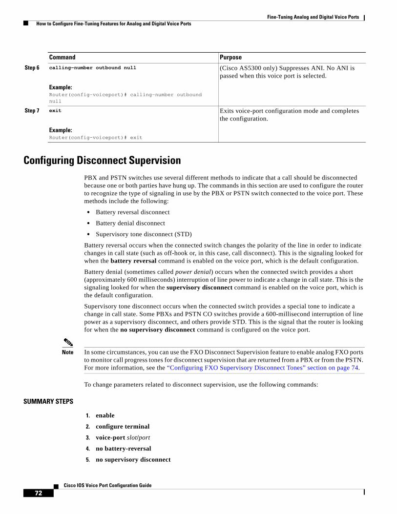
Fine-Tuning Analog and Digital Voice Ports How to Configure Fine-Tuning Features for Analog and Digital Voice Ports
72Cisco IOS Voice Port Configuration Guide
Configuring Disconnect SupervisionPBX and PSTN switches use several different methods to indicate that a call should be disconnected because one or both parties have hung up. The commands in this section are used to configure the router to recognize the type of signaling in use by the PBX or PSTN switch connected to the voice port. These methods include the following:
• Battery reversal disconnect
• Battery denial disconnect
• Supervisory tone disconnect (STD)
Battery reversal occurs when the connected switch changes the polarity of the line in order to indicate changes in call state (such as off-hook or, in this case, call disconnect). This is the signaling looked for when the battery reversal command is enabled on the voice port, which is the default configuration.
Battery denial (sometimes called power denial) occurs when the connected switch provides a short (approximately 600 milliseconds) interruption of line power to indicate a change in call state. This is the signaling looked for when the supervisory disconnect command is enabled on the voice port, which is the default configuration.
Supervisory tone disconnect occurs when the connected switch provides a special tone to indicate a change in call state. Some PBXs and PSTN CO switches provide a 600-millisecond interruption of line power as a supervisory disconnect, and others provide STD. This is the signal that the router is looking for when the no supervisory disconnect command is configured on the voice port.
Note In some circumstances, you can use the FXO Disconnect Supervision feature to enable analog FXO ports to monitor call progress tones for disconnect supervision that are returned from a PBX or from the PSTN. For more information, see the “Configuring FXO Supervisory Disconnect Tones” section on page 74.
To change parameters related to disconnect supervision, use the following commands:
SUMMARY STEPS
1. enable
2. configure terminal
3. voice-port slot/port
4. no battery-reversal
5. no supervisory disconnect
Step 6 calling-number outbound null
Example:Router(config-voiceport)# calling-number outbound null
(Cisco AS5300 only) Suppresses ANI. No ANI is passed when this voice port is selected.
Step 7 exit
Example:Router(config-voiceport)# exit
Exits voice-port configuration mode and completes the configuration.
Command Purpose

Fine-Tuning Analog and Digital Voice Ports How to Configure Fine-Tuning Features for Analog and Digital Voice Ports
73Cisco IOS Voice Port Configuration Guide
6. disconnect-ack
7. exit
DETAILED STEPS
Command Purpose
Step 1 enable
Example:Router> enable
Enables privileged EXEC mode.
• Enter your password if prompted.
Step 2 configure terminal
Example:Router# configure terminal
Enters global configuration mode.
Step 3 voice-port slot/port
Example:Router(config)# voice-port 3/0
Enters voice-port configuration mode.
Note The syntax of this command is platform-specific. For the syntax for your platform, refer to the Cisco IOS Voice Command Reference.
Step 4 no battery-reversal
Example:Router(config-voiceport)# no battery-reversal
(Analog only) Enables battery reversal. The default is that battery reversal is enabled.
• For FXO ports—Use the no battery-reversal command to configure a loop-start voice port not to disconnect when it detects a second battery reversal. The default is to disconnect when a second battery reversal is detected.
Note This functionality is supported on Cisco 1750, Cisco 2600 series, and Cisco 3600 series routers; only analog voice ports on VIC-2FXO cards are able to detect battery reversal.
Also use the no battery-reversal command when a connected FXO port does not support battery reversal detection.
• For FXS ports—Use the no battery-reversal command to configure the voice port not to reverse battery when it connects calls. The default is to reverse battery when a call is connected, then return to normal when the call is over, providing positive disconnect.
See also the disconnect-ack command (Step 6).
Step 5 no supervisory disconnect
Example:Router(config-voiceport)# no supervisory disconnect
(FXO only) Enables the PBX or PSTN switch to provide STD. The supervisory disconnect command is enabled by default.
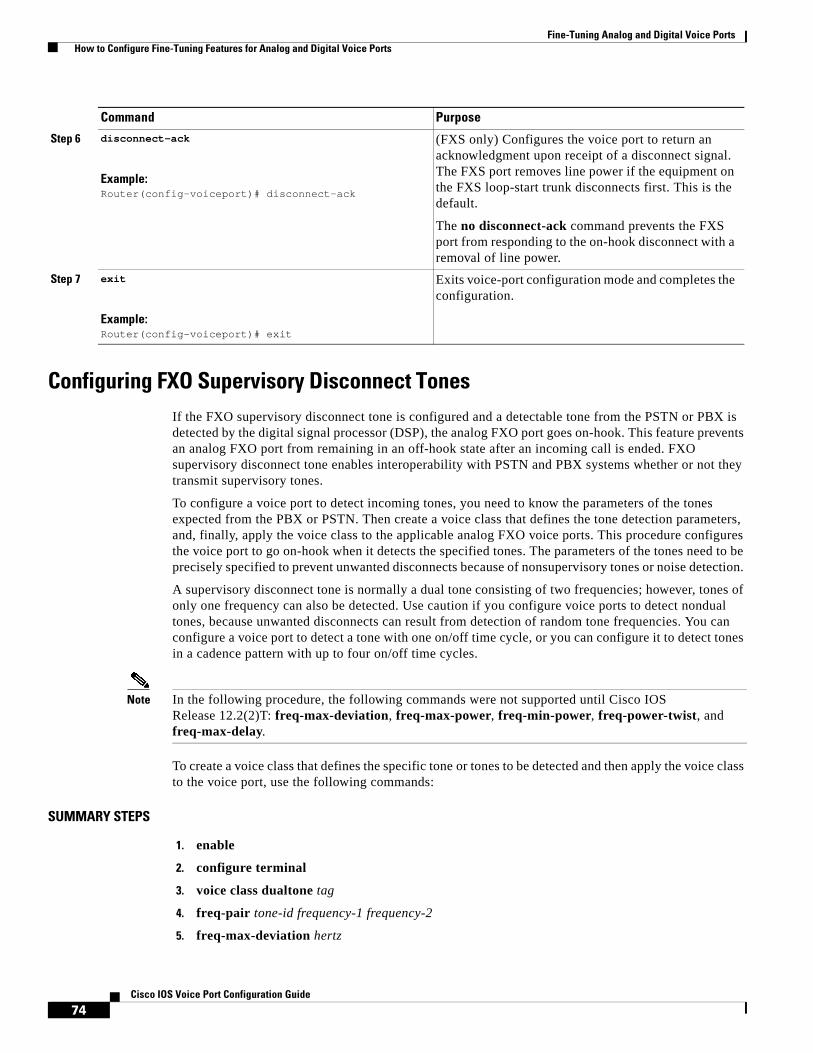
Fine-Tuning Analog and Digital Voice Ports How to Configure Fine-Tuning Features for Analog and Digital Voice Ports
74Cisco IOS Voice Port Configuration Guide
Configuring FXO Supervisory Disconnect TonesIf the FXO supervisory disconnect tone is configured and a detectable tone from the PSTN or PBX is detected by the digital signal processor (DSP), the analog FXO port goes on-hook. This feature prevents an analog FXO port from remaining in an off-hook state after an incoming call is ended. FXO supervisory disconnect tone enables interoperability with PSTN and PBX systems whether or not they transmit supervisory tones.
To configure a voice port to detect incoming tones, you need to know the parameters of the tones expected from the PBX or PSTN. Then create a voice class that defines the tone detection parameters, and, finally, apply the voice class to the applicable analog FXO voice ports. This procedure configures the voice port to go on-hook when it detects the specified tones. The parameters of the tones need to be precisely specified to prevent unwanted disconnects because of nonsupervisory tones or noise detection.
A supervisory disconnect tone is normally a dual tone consisting of two frequencies; however, tones of only one frequency can also be detected. Use caution if you configure voice ports to detect nondual tones, because unwanted disconnects can result from detection of random tone frequencies. You can configure a voice port to detect a tone with one on/off time cycle, or you can configure it to detect tones in a cadence pattern with up to four on/off time cycles.
Note In the following procedure, the following commands were not supported until Cisco IOS Release 12.2(2)T: freq-max-deviation, freq-max-power, freq-min-power, freq-power-twist, and freq-max-delay.
To create a voice class that defines the specific tone or tones to be detected and then apply the voice class to the voice port, use the following commands:
SUMMARY STEPS
1. enable
2. configure terminal
3. voice class dualtone tag
4. freq-pair tone-id frequency-1 frequency-2
5. freq-max-deviation hertz
Step 6 disconnect-ack
Example:Router(config-voiceport)# disconnect-ack
(FXS only) Configures the voice port to return an acknowledgment upon receipt of a disconnect signal. The FXS port removes line power if the equipment on the FXS loop-start trunk disconnects first. This is the default.
The no disconnect-ack command prevents the FXS port from responding to the on-hook disconnect with a removal of line power.
Step 7 exit
Example:Router(config-voiceport)# exit
Exits voice-port configuration mode and completes the configuration.
Command Purpose

Fine-Tuning Analog and Digital Voice Ports How to Configure Fine-Tuning Features for Analog and Digital Voice Ports
75Cisco IOS Voice Port Configuration Guide
6. freq-max-power dBmO
7. freq-min-power dBmO
8. freq-power-twist dBmO
9. freq-max-delay milliseconds
10. cadence-min-on-time milliseconds
11. cadence-max-off-time milliseconds
12. cadence-list cadence-id cycle-1-on-time cycle-1-off-time [cycle-2-on-time cycle-2-off-time] [cycle-3-on-time cycle-3-off-time] [cycle-4-on-time cycle-4-off-time]
13. cadence-variation milliseconds
14. exit
15. voice-port slot/subunit/port
16. supervisory disconnect dualtone {mid-call | pre-connect} voice-class tag
17. supervisory disconnect anytone
18. exit
DETAILED STEPS
Command Purpose
Step 1 enable
Example:Router> enable
Enables privileged EXEC mode.
• Enter your password if prompted.
Step 2 configure terminal
Example:Router# configure terminal
Enters global configuration mode.
Step 3 voice class dualtone tag
Example:Router(config)# voice class dualtone 1
Enters voice-class configuration mode and creates a voice class for defining one tone detection pattern. Range is 1 to 10000. The tag number must be unique on the router.
• For more information about configuring voice classes, refer to the Dial Peer Configuration onVoice Gateway Routers.
Step 4 freq-pair tone-id frequency-1 frequency-2
Example:Router(config-voice-class)# freq-pair 16 300 0
Specifies the two frequencies, in Hz, for a tone to be detected (or one frequency if a nondual tone is to be detected). If the tone to be detected contains only one frequency, enter 0 for frequency-2.
Note Repeat this command for each additional tone to be specified.
Step 5 freq-max-deviation hertz
Example:Router(config-voice-class)# freq-max-deviation 10
Specifies the maximum frequency deviation that will be detected, in Hz. Range is 10 to 125. Default is 10.
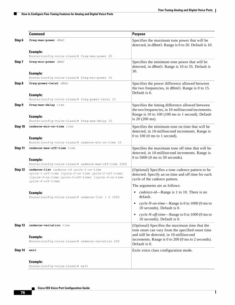
Fine-Tuning Analog and Digital Voice Ports How to Configure Fine-Tuning Features for Analog and Digital Voice Ports
76Cisco IOS Voice Port Configuration Guide
Step 6 freq-max-power dBmO
Example:Router(config-voice-class)# freq-max-power 20
Specifies the maximum tone power that will be detected, in dBmO. Range is 0 to 20. Default is 10.
Step 7 freq-min-power dBmO
Example:Router(config-voice-class)# freq-min-power 35
Specifies the minimum tone power that will be detected, in dBmO. Range is 10 to 35. Default is 30.
Step 8 freq-power-twist dBmO
Example:Router(config-voice-class)# freq-power-twist 15
Specifies the power difference allowed between the two frequencies, in dBmO. Range is 0 to 15. Default is 6.
Step 9 freq-max-delay time
Example:Router(config-voice-class)# freq-max-delay 10
Specifies the timing difference allowed between the two frequencies, in 10-millisecond increments. Range is 10 to 100 (100 ms to 1 second). Default is 20 (200 ms).
Step 10 cadence-min-on-time time
Example:Router(config-voice-class)# cadence-min-on-time 10
Specifies the minimum tone on time that will be detected, in 10-millisecond increments. Range is 0 to 100 (0 ms to 1 second).
Step 11 cadence-max-off-time time
Example:Router(config-voice-class)# cadence-max-off-time 2000
Specifies the maximum tone off time that will be detected, in 10-millisecond increments. Range is 0 to 5000 (0 ms to 50 seconds).
Step 12 cadence-list cadence-id cycle-1-on-time cycle-1-off-time [cycle-2-on-time cycle-2-off-time] [cycle-3-on-time cycle-3-off-time] [cycle-4-on-time cycle-4-off-time]
Example:Router(config-voice-class)# cadence-list 1 0 1000
(Optional) Specifies a tone cadence pattern to be detected. Specify an on time and off time for each cycle of the cadence pattern.
The arguments are as follows:
• cadence-id—Range is 1 to 10. There is no default.
• cycle-N-on-time—Range is 0 to 1000 (0 ms to 10 seconds). Default is 0.
• cycle-N-off-time—Range is 0 to 1000 (0 ms to 10 seconds). Default is 0.
Step 13 cadence-variation time
Example:Router(config-voice-class)# cadence-variation 200
(Optional) Specifies the maximum time that the tone onset can vary from the specified onset time and still be detected, in 10-millisecond increments. Range is 0 to 200 (0 ms to 2 seconds). Default is 0.
Step 14 exit
Example:Router(config-voice-class)# exit
Exits voice class configuration mode.
Command Purpose
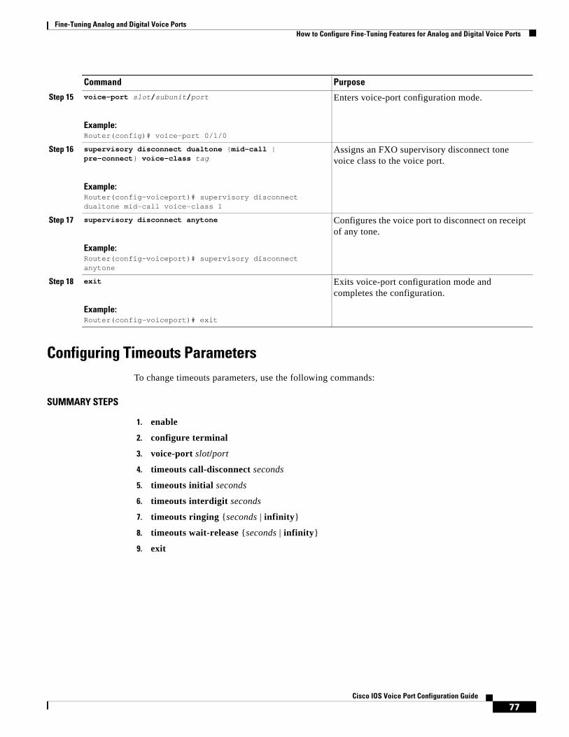
Fine-Tuning Analog and Digital Voice Ports How to Configure Fine-Tuning Features for Analog and Digital Voice Ports
77Cisco IOS Voice Port Configuration Guide
Configuring Timeouts ParametersTo change timeouts parameters, use the following commands:
SUMMARY STEPS
1. enable
2. configure terminal
3. voice-port slot/port
4. timeouts call-disconnect seconds
5. timeouts initial seconds
6. timeouts interdigit seconds
7. timeouts ringing {seconds | infinity}
8. timeouts wait-release {seconds | infinity}
9. exit
Step 15 voice-port slot/subunit/port
Example:Router(config)# voice-port 0/1/0
Enters voice-port configuration mode.
Step 16 supervisory disconnect dualtone {mid-call | pre-connect} voice-class tag
Example:Router(config-voiceport)# supervisory disconnect dualtone mid-call voice-class 1
Assigns an FXO supervisory disconnect tone voice class to the voice port.
Step 17 supervisory disconnect anytone
Example:Router(config-voiceport)# supervisory disconnect anytone
Configures the voice port to disconnect on receipt of any tone.
Step 18 exit
Example:Router(config-voiceport)# exit
Exits voice-port configuration mode and completes the configuration.
Command Purpose

Fine-Tuning Analog and Digital Voice Ports How to Configure Fine-Tuning Features for Analog and Digital Voice Ports
78Cisco IOS Voice Port Configuration Guide
DETAILED STEPS
Command Purpose
Step 1 enable
Example:Router> enable
Enables privileged EXEC mode.
• Enter your password if prompted.
Step 2 configure terminal
Example:Router# configure terminal
Enters global configuration mode.
Step 3 voice-port slot/port
Example:Router(config)# voice-port 3/0
Enters voice-port configuration mode.
Note The syntax of this command is platform-specific. For the syntax for your platform, refer to the Cisco IOS Voice Command Reference.
Step 4 timeouts call-disconnect seconds
Example:Router(config-voiceport)# timeouts call-disconnect 60
Configures the call disconnect timeout value in seconds. Range is 0 to 120. Default is 60.
Step 5 timeouts initial seconds
Example:Router(config-voiceport)# timeouts initial 10
Sets the number of seconds that the system waits between the caller input of the initial digit and the subsequent digit of the dialed string. If the wait time expires before the destination is identified, a tone sounds and the call ends.
• The seconds argument is the initial timeout duration. Range is 0 to 120. Default is 10.
Step 6 timeouts interdigit seconds
Example:Router(config-voiceport)# timeouts interdigit 10
Configures the number of seconds that the system waits after the caller has input the initial digit or a subsequent digit of the dialed string. If the timeout ends before the destination is identified, a tone sounds and the call ends. This value is important when you are using variable-length dial peer destination patterns (dial plans).
• The seconds argument is the interdigit timeout wait time in seconds. Range is 0 to 120. Default is 10.
Step 7 timeouts ringing {seconds | infinity}
Example:Router(config-voiceport)# timeouts ringing infinity
Specifies the duration that the voice port allows ringing to continue if a call is not answered.
• Default for seconds is 180.

Fine-Tuning Analog and Digital Voice Ports How to Configure Fine-Tuning Features for Analog and Digital Voice Ports
79Cisco IOS Voice Port Configuration Guide
Changing Timing ParametersTo change timing parameters, use the following commands:
SUMMARY STEPS
1. enable
2. configure terminal
3. voice-port slot/port
4. timing clear-wait milliseconds
5. timing delay-duration milliseconds
6. timing delay-start milliseconds
7. timing delay-with-integrity milliseconds
8. timing dial-pulse min-delay milliseconds
9. timing dialout-delay millisecond
10. timing digit milliseconds
11. timing guard-out milliseconds
12. timing hookflash-out milliseconds
13. timing interdigit milliseconds
14. timing percentbreak percent
15. timing pulse pulses-per-second
16. timing pulse-digit milliseconds
17. timing pulse-interdigit milliseconds
18. timing wink-duration milliseconds
19. timing wink-wait milliseconds
20. exit
Step 8 timeouts wait-release {seconds | infinity}
Example:Router(config-voiceport)# timeouts wait-release 30
Specifies the duration that a voice port stays in the call-failure state while the Cisco device sends a busy tone, reorder tone, or an out-of-service tone to the port.
• Default for seconds is 30.
Step 9 exit
Example:Router(config-voiceport)# exit
Exits voice-port configuration mode and completes the configuration.
Command Purpose

Fine-Tuning Analog and Digital Voice Ports How to Configure Fine-Tuning Features for Analog and Digital Voice Ports
80Cisco IOS Voice Port Configuration Guide
DETAILED STEPS
Command Purpose
Step 1 enable
Example:Router> enable
Enables privileged EXEC mode.
• Enter your password if prompted.
Step 2 configure terminal
Example:Router# configure terminal
Enters global configuration mode.
Step 3 voice-port slot/port
Example:Router(config)# voice-port 3/0
Enters voice-port configuration mode.
Note The syntax of this command is platform-specific. For the syntax for your platform, refer to the Cisco IOS Voice Command Reference.
Step 4 timing clear-wait milliseconds
Example:Router(config-voiceport)# timing clear-wait 200
(E&M only) Specifies the minimum amount of time, in milliseconds, between the inactive seizure signal and clearing of the call.
• Range is 200 to 2000. Default is 400.
Step 5 timing delay-duration milliseconds
Example:Router(config-voiceport)# timing delay-duration 100
(E&M only) Specifies the delay signal duration for delay-dial signaling, in milliseconds.
• Range is 100 to 5000. Default is 2000.
Step 6 timing delay-start milliseconds
Example:Router(config-voiceport)# timing delay-start milliseconds
(E&M only) Specifies minimum delay time, in milliseconds, from outgoing seizure to outdial address.
• Range is 20 to 2000. Default is 300.
Step 7 timing delay-with-integrity milliseconds
Example:Router(config-voiceport)# timing delay-with-integrity 0
(Cisco MC3810 E&M ports only) Specifies duration of the wink pulse for the delay dial, in milliseconds.
• Range is 0 to 5000. Default is 0.
Step 8 timing dial-pulse min-delay milliseconds
Example:Router(config-voiceport)# timing dial-pulse min-delay 300
Specifies time, in milliseconds, between the generation of wink-like pulses when the type is pulse.
• Range is 0 to 5000. Default is 300 for Cisco 3600 series and 140 for Cisco MC3810.
Step 9 timing dialout-delay milliseconds
Example:Router(config-voiceport)# timing dialout-delay 100
(Cisco MC3810 only) Specifies dial-out delay, in milliseconds, for the sending digit or cut-through on an FXO trunk or an E&M immediate trunk.
• Range is 100 to 5000. Default is 300.

Fine-Tuning Analog and Digital Voice Ports How to Configure Fine-Tuning Features for Analog and Digital Voice Ports
81Cisco IOS Voice Port Configuration Guide
Step 10 timing digit milliseconds
Example:Router(config-voiceport)# timing digit 50
Specifies the DTMF digit signal duration in milliseconds.
• Range is 50 to 100. Default is 100.
Step 11 timing guard-out milliseconds
Example:Router(config-voiceport)# timing guard-out 300
(FXO ports only) Specifies the duration in milliseconds of the guard-out period that prevents this port from seizing a remote FXS port before the remote port detects a disconnect signal.
• Range is 300 to 3000. Default is 2000.
Step 12 timing hookflash-out milliseconds
Example:Router(config-voiceport)# timing hookflash-out 500
Specifies the duration, in milliseconds, of the hookflash.
• Range is 50 to 500. Default is 300.
Step 13 timing interdigit milliseconds
Example:Router(config-voiceport)# timing interdigit 100
Specifies the dual-tone multifrequency (DTMF) interdigit duration, in milliseconds.
• Range is 50 to 500. Default is 100.
Step 14 timing percentbreak percent
Example:Router(config-voiceport)# timing percentbreak 20
(Cisco MC3810 FXO and E&M ports only) Specifies the percentage of the break period for the dialing pulses, if different from the default.
• Range is 20 to 80. Default is 50.
Step 15 timing pulse pulses-per-second
Example:Router(config-voiceport)# timing pulse 20
(FXO and E&M only) Specifies the pulse dialing rate in pulses per second.
• Range is 10 to 20. Default is 20.
Step 16 timing pulse-digit milliseconds
Example:Router(config-voiceport)# timing pulse-digit 10
(FXO only) Configures the pulse digit signal duration.
• Range is 10 to 20. Default is 20.
Step 17 timing pulse-interdigit milliseconds
Example:Router(config-voiceport)# timing pulse-interdigit 500
(FXO and E&M only) Specifies pulse dialing interdigit timing in milliseconds.
• Range is 100 to 1000. Default is 500.
Step 18 timing wink-duration milliseconds
Example:Router(config-voiceport)# timing wink-duration 200
(E&M only) Specifies maximum wink-signal duration, in milliseconds, for a wink-start signal.
• Range is 100 to 400. Default is 200.
Command Purpose

Fine-Tuning Analog and Digital Voice Ports How to Configure Fine-Tuning Features for Analog and Digital Voice Ports
82Cisco IOS Voice Port Configuration Guide
Configuring the DTMF TimerTo configure the DTMF timer, use the following commands:
SUMMARY STEPS
1. enable
2. configure terminal
3. controller T1 number
4. ds0-group channel-number timeslots range type signaling-type dtmf dnis
5. cas-custom channel
6. dtmf timer-inter-digit milliseconds
7. exit
DETAILED STEPS
Step 19 timing wink-wait milliseconds
Example:Router(config-voiceport)# timing wink-wait 200
(E&M only) Specifies maximum wink-wait duration, in milliseconds, for a wink-start signal.
• Range is 100 to 5000. Default is 200.
Step 20 exit
Example:Router(config-voiceport)# exit
Exits voice-port configuration mode and completes the configuration.
Command Purpose
Command Purpose
Step 1 enable
Example:Router> enable
Enables privileged EXEC mode.
• Enter your password if prompted.
Step 2 configure terminal
Example:Router# configure terminal
Enters global configuration mode.
Step 3 controller T1 number
Example:Router(config)# controller T1 1
Configures a T1 controller and enters controller configuration mode.

Fine-Tuning Analog and Digital Voice Ports How to Configure Fine-Tuning Features for Analog and Digital Voice Ports
83Cisco IOS Voice Port Configuration Guide
Configuring Comfort Noise and Music Threshold for VADIn normal voice conversations, only one person speaks at a time. Circuit-switched telephone networks dedicate a bidirectional 64 kbps channel for the duration of each conversation, regardless of whether anyone is speaking at the moment. This means that, in a normal voice conversation, at least 50 percent of the bandwidth is wasted when one or both parties are silent. This figure can actually be much higher when normal pauses and breaks in conversation are taken into account.
Packet-switched voice networks can use this “wasted” bandwidth for other purposes when voice activity detection (VAD) is configured. VAD works by detecting the magnitude of speech in decibels and deciding when to stop segmenting voice packets into frames. VAD has some technological problems, however, which include the following:
• General difficulties determining when speech ends
• Clipped speech when VAD is slow to detect that speech is beginning again
• Automatic disabling of VAD when conversations take place in noisy surroundings
VAD is configured in dial peers; by default it is enabled. Two parameters associated with VAD, music threshold and comfort noise, are configured on voice ports.
If VAD is enabled, use the following commands to adjust music threshold and comfort noise:
Step 4 ds0-group channel-number timeslots range type signaling-type dtmf dnis
Example:Router(config-controller)# ds0-group 0 timeslots 1-4 type e&m-immediate-start dtmf dnis
Configures channelized T1 time slots, which enables a Cisco AS5300 modem to answer and send an analog call.
Step 5 cas-custom channel
Example:Router(config-controller)# cas-custom 2
Enters cas-controller configuration mode and customizes signaling parameters for a particular E1 or T1 channel group on a channelized line.
Step 6 dtmf timer-inter-digit milliseconds
Example:Router(conf-ctrl-cas)# dtmf timer-inter-digit 100
Configures the DTMF interdigit timer for a DS0 group.
Step 7 exit
Example:Router(conf-ctrl-cas)# exit
Exits cas-controller configuration mode and completes the configuration.
Command Purpose

Fine-Tuning Analog and Digital Voice Ports How to Configure Fine-Tuning Features for Analog and Digital Voice Ports
84Cisco IOS Voice Port Configuration Guide
SUMMARY STEPS
1. enable
2. configure terminal
3. dial-peer voice tag voip
4. vad [aggressive]
5. exit
6. voice vad-time milliseconds
7. voice-port slot/port
8. music-threshold number
9. comfort-noise
10. exit
DETAILED STEPS
Command Purpose
Step 1 enable
Example:Router> enable
Enables privileged EXEC mode.
• Enter your password if prompted.
Step 2 configure terminal
Example:Router# configure terminal
Enters global configuration mode.
Step 3 dial-peer voice tag voip
Example:Router(config)# dial-peer voice 555 voip
Enters dial-peer configuration mode.
Step 4 vad [aggressive]
Example:Router(config-dial-peer)# vad
Enables VAD for calls using this dial peer.
Note VAD is enabled by default. Use the vad command only if you have previously disabled the feature by using the no vad command.
Step 5 exit
Example:Router(config-dial-peer)# exit
Exits dial-peer configuration mode.
Step 6 voice vad-time milliseconds
Example:Router(config)# voice vad-time 500
Modifies the minimum silence detection time for VAD.
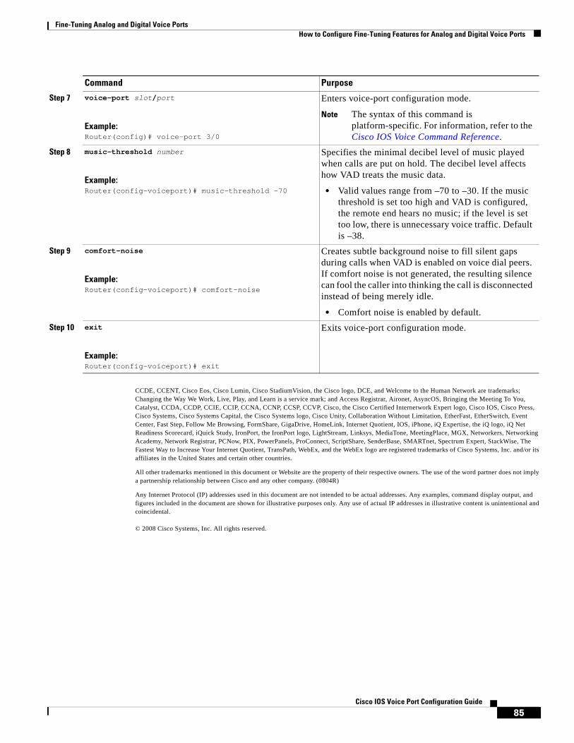
Fine-Tuning Analog and Digital Voice Ports How to Configure Fine-Tuning Features for Analog and Digital Voice Ports
85Cisco IOS Voice Port Configuration Guide
CCDE, CCENT, Cisco Eos, Cisco Lumin, Cisco StadiumVision, the Cisco logo, DCE, and Welcome to the Human Network are trademarks; Changing the Way We Work, Live, Play, and Learn is a service mark; and Access Registrar, Aironet, AsyncOS, Bringing the Meeting To You, Catalyst, CCDA, CCDP, CCIE, CCIP, CCNA, CCNP, CCSP, CCVP, Cisco, the Cisco Certified Internetwork Expert logo, Cisco IOS, Cisco Press, Cisco Systems, Cisco Systems Capital, the Cisco Systems logo, Cisco Unity, Collaboration Without Limitation, EtherFast, EtherSwitch, Event Center, Fast Step, Follow Me Browsing, FormShare, GigaDrive, HomeLink, Internet Quotient, IOS, iPhone, iQ Expertise, the iQ logo, iQ Net Readiness Scorecard, iQuick Study, IronPort, the IronPort logo, LightStream, Linksys, MediaTone, MeetingPlace, MGX, Networkers, Networking Academy, Network Registrar, PCNow, PIX, PowerPanels, ProConnect, ScriptShare, SenderBase, SMARTnet, Spectrum Expert, StackWise, The Fastest Way to Increase Your Internet Quotient, TransPath, WebEx, and the WebEx logo are registered trademarks of Cisco Systems, Inc. and/or its affiliates in the United States and certain other countries.
All other trademarks mentioned in this document or Website are the property of their respective owners. The use of the word partner does not imply a partnership relationship between Cisco and any other company. (0804R)
Any Internet Protocol (IP) addresses used in this document are not intended to be actual addresses. Any examples, command display output, and figures included in the document are shown for illustrative purposes only. Any use of actual IP addresses in illustrative content is unintentional and coincidental.
© 2008 Cisco Systems, Inc. All rights reserved.
Step 7 voice-port slot/port
Example:Router(config)# voice-port 3/0
Enters voice-port configuration mode.
Note The syntax of this command is platform-specific. For information, refer to the Cisco IOS Voice Command Reference.
Step 8 music-threshold number
Example:Router(config-voiceport)# music-threshold -70
Specifies the minimal decibel level of music played when calls are put on hold. The decibel level affects how VAD treats the music data.
• Valid values range from –70 to –30. If the music threshold is set too high and VAD is configured, the remote end hears no music; if the level is set too low, there is unnecessary voice traffic. Default is –38.
Step 9 comfort-noise
Example:Router(config-voiceport)# comfort-noise
Creates subtle background noise to fill silent gaps during calls when VAD is enabled on voice dial peers. If comfort noise is not generated, the resulting silence can fool the caller into thinking the call is disconnected instead of being merely idle.
• Comfort noise is enabled by default.
Step 10 exit
Example:Router(config-voiceport)# exit
Exits voice-port configuration mode.
Command Purpose

Fine-Tuning Analog and Digital Voice Ports How to Configure Fine-Tuning Features for Analog and Digital Voice Ports
86Cisco IOS Voice Port Configuration Guide

Americas Headquarters:Cisco Systems, Inc., 170 West Tasman Drive, San Jose, CA 95134-1706 USA
© 2008 Cisco Systems, Inc. All rights reserved.
Configuring Echo Cancellation
Echo cancellation is a key function in packet voice. Much of the perceived quality of the connection depends on the performance of the echo canceller. The G.168 extended echo cancellation (EC) provides an alternative to the proprietary Cisco G.165 EC with improved performance for trunking gateway applications.
The following sections provide configuration information for echo cancellation:
• Information About Echo Cancellation, page 87
• How to Configure the Extended G.168 Echo Canceller, page 95
• Configuration Examples for Extended G.168 Echo Cancellation, page 104
Information About Echo CancellationTo use the feature, you should understand the following concepts:
• Voice Call Transmit and Receive Paths, page 87
• Echo Cancellation, page 88
• Echo Canceller Operation, page 89
• Echo Canceller Components, page 90
• Echo Canceller Coverage, page 90
• ITU-T Echo Cancellation History, page 91
• Extended G.168 Echo Canceller Features, page 92
• Extended EC Comparison, page 92
• Extended Echo Canceller Support by Platform, page 93
Voice Call Transmit and Receive PathsEvery voice conversation has at least two participants. From the perspective of each participant, there are two voice paths in every call:

Configuring Echo Cancellation Information About Echo Cancellation
88Cisco IOS Voice Port Configuration Guide
• Transmit path (also called the send or Tx path)—The transmit path is created when a person speaks. The sound is transmitted from the mouth of the speaker to the ear of the listener.
• Receive path (also called the return or Rx path)—The receive path is created when a person hears the conversation. The sound is received by the ear of the listener from the mouth of the speaker.
Figure 1 shows a simple voice call between caller A and caller B. The top line represents the Tx path for caller A, which becomes the Rx path for caller B. The bottom line represents the Tx path for caller B, which becomes the Rx path for caller A.
Figure 1 Transmit and Receive Paths in a Voice Network
Echo CancellationEcho is the sound of your own voice reverberating in the telephone receiver while you are talking. When timed properly, echo is not a problem in the conversation; however, if the echo interval exceeds approximately 25 milliseconds (ms), it can be distracting to the speaker. In the traditional telephony network, echo is generally caused by an impedance mismatch when the four-wire network is converted to the two-wire local loop. Echo is controlled by echo cancellers (ECs).
A packet voice gateway, which operates between a digital packet network and the PSTN, can include both digital (time division multiplexing [TDM]) and analog links. The analog circuit is known as the tail circuit. It forms the tail or termination of the call from the perspective of the person experiencing the echo. The tail circuit is everything connected to the PSTN side of a packet voice gateway—all the switches, multiplexers, cabling, and PBXs between the voice gateway and the telephone.
Figure 2 shows a common voice network where echo cancellation might be used.
Figure 2 Echo Cancellation Network
An echo canceller reduces the level of echoes that leak from the Rx path (from the gateway out into the tail circuit) into the Tx path (from the tail circuit into the gateway). From the perspective of the echo canceller in a voice gateway, the Rx signal is a voice coming across the network from another location. The Tx signal is a mixture of the voice call in the other location and the echo of the original voice, which comes from the tail circuit on the initiating end and is sent to the receiving end.
88
56
0
Voice network
Tx
Rx
Rx
TxA BB's voice
A's voice
V V
IP
6208
6Analog Analog
IP phone
Digital DigitalE0 E0
PSTN PSTN
IP network

Configuring Echo Cancellation Information About Echo Cancellation
89Cisco IOS Voice Port Configuration Guide
Echo cancellers face into the PSTN tail circuit. They eliminate echoes in the tail circuit on its side of the network.The echo canceller in the originating gateway looks out into the tail circuit and is responsible for eliminating the echo signal from the initiation Tx signal and allowing a voice call to go through unimpeded. By design, ECs are limited by the total amount of time they wait for the reflected speech to be received, which is known as an echo tail. The echo tail is normally 32 ms.
Note Delay and jitter in the WAN do not affect the operation of the echo canceller because the tail circuit, where the echo canceller operates, is static.
Echo cancellation is implemented in digital signal processor (DSP) firmware (DSPWare) on Cisco voice gateways and is independent of other functions implemented in the DSP (the DSP protocol and compression algorithm). In voice packet-based networks, ECs are built into the low-bit-rate codecs and are operated on each DSP.
Figure 3 shows a typical DSP channel configured for voice processing.
Figure 3 DSP Channel Configured for Voice Processing
Echo Canceller OperationAn echo canceller removes the echo portion of the signal coming out of the tail circuit and headed into the WAN. It does so by learning the electrical characteristics of the tail circuit and forming its own model of the tail circuit in its memory, and creating an estimated echo signal based on the current and past Rx signal. It subtracts the estimated echo from the actual Tx signal coming out of the tail circuit. The quality of the estimation is continuously improved by monitoring the estimation error.
Following are descriptions of the primary measurements of relative signal levels used by echo cancellers. They are all expressed in decibels (dB).
• Echo return loss (ERL)—Reduction in the echo level produced by the tail circuit without the use of an echo canceller. If an Rx speech signal enters the tail circuit from the network at a level of X dB, the echo coming back from the tail circuit into the echo canceller is X less ERL.
Telephonyinterface
Tone generationand detection
DTMFcall progress
PCM interface
Echo canceller
Fax detection
Speech coderPacketizer
anddejitterer
Managementinterface
Host interface
RTOS
Data flowControl flow 56
406
Voice activitydetection
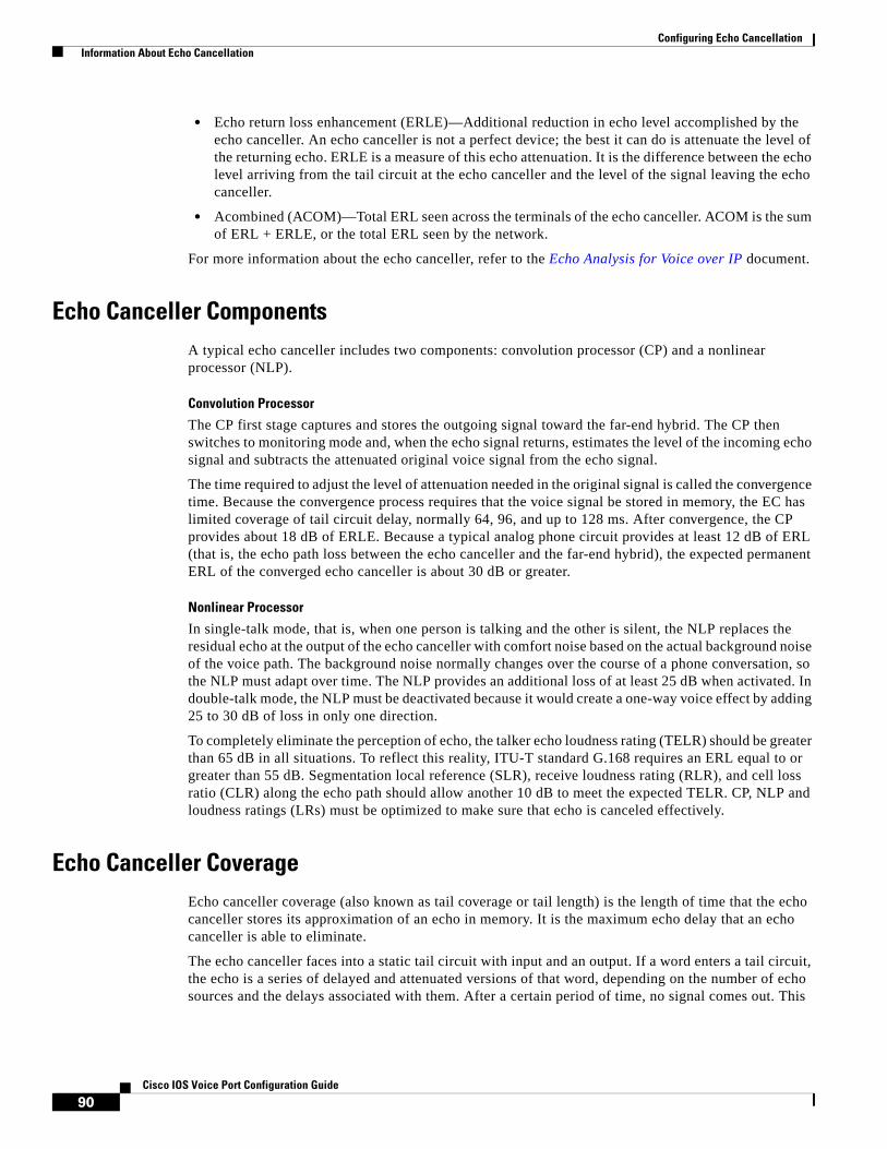
Configuring Echo Cancellation Information About Echo Cancellation
90Cisco IOS Voice Port Configuration Guide
• Echo return loss enhancement (ERLE)—Additional reduction in echo level accomplished by the echo canceller. An echo canceller is not a perfect device; the best it can do is attenuate the level of the returning echo. ERLE is a measure of this echo attenuation. It is the difference between the echo level arriving from the tail circuit at the echo canceller and the level of the signal leaving the echo canceller.
• Acombined (ACOM)—Total ERL seen across the terminals of the echo canceller. ACOM is the sum of ERL + ERLE, or the total ERL seen by the network.
For more information about the echo canceller, refer to the Echo Analysis for Voice over IP document.
Echo Canceller ComponentsA typical echo canceller includes two components: convolution processor (CP) and a nonlinear processor (NLP).
Convolution Processor
The CP first stage captures and stores the outgoing signal toward the far-end hybrid. The CP then switches to monitoring mode and, when the echo signal returns, estimates the level of the incoming echo signal and subtracts the attenuated original voice signal from the echo signal.
The time required to adjust the level of attenuation needed in the original signal is called the convergence time. Because the convergence process requires that the voice signal be stored in memory, the EC has limited coverage of tail circuit delay, normally 64, 96, and up to 128 ms. After convergence, the CP provides about 18 dB of ERLE. Because a typical analog phone circuit provides at least 12 dB of ERL (that is, the echo path loss between the echo canceller and the far-end hybrid), the expected permanent ERL of the converged echo canceller is about 30 dB or greater.
Nonlinear Processor
In single-talk mode, that is, when one person is talking and the other is silent, the NLP replaces the residual echo at the output of the echo canceller with comfort noise based on the actual background noise of the voice path. The background noise normally changes over the course of a phone conversation, so the NLP must adapt over time. The NLP provides an additional loss of at least 25 dB when activated. In double-talk mode, the NLP must be deactivated because it would create a one-way voice effect by adding 25 to 30 dB of loss in only one direction.
To completely eliminate the perception of echo, the talker echo loudness rating (TELR) should be greater than 65 dB in all situations. To reflect this reality, ITU-T standard G.168 requires an ERL equal to or greater than 55 dB. Segmentation local reference (SLR), receive loudness rating (RLR), and cell loss ratio (CLR) along the echo path should allow another 10 dB to meet the expected TELR. CP, NLP and loudness ratings (LRs) must be optimized to make sure that echo is canceled effectively.
Echo Canceller CoverageEcho canceller coverage (also known as tail coverage or tail length) is the length of time that the echo canceller stores its approximation of an echo in memory. It is the maximum echo delay that an echo canceller is able to eliminate.
The echo canceller faces into a static tail circuit with input and an output. If a word enters a tail circuit, the echo is a series of delayed and attenuated versions of that word, depending on the number of echo sources and the delays associated with them. After a certain period of time, no signal comes out. This

Configuring Echo Cancellation Information About Echo Cancellation
91Cisco IOS Voice Port Configuration Guide
time period is known as the ringing time of the tail circuit—the time required for all of the ripples to disperse. To fully eliminate all echoes, the coverage of the echo canceller must be as long as the ringing time of the tail circuit.
ITU-T Echo Cancellation HistoryITU-T standard G.164 defines the performance of echo suppressors, which are the predecessors of echo cancellation technology. G.164 also defines the disabling of echo suppressors in the presence of 2100 Hz tones (which precede low bit rate modems).
ITU-T standard G.165 defines echo cancellation and provides a number of objective tests that ensure a minimum level of performance. These tests check convergence speed of the echo canceller, stability of the echo canceller filter, performance of the nonlinear processor, and a limited amount of double talk testing. The signal used to perform these tests is white noise. Additionally, G.165 defines the disabling of echo cancellers in the presence of 2100 Hz signals with periodic phase reversals in order to support echo cancelling modem technology (V.34, for example), which does not work if line echo cancellation is performed in the connection.
ITU-T standard G.168 allows more rigorous testing and satisfies more testing requirements. White noise is replaced with a pseudospeech signal for the convergence tests. Most echo cancellation algorithms use a least mean square (LMS) algorithm to adapt the echo cancellation filter. LMS works best with random signals, and slows down with more correlated signals such as speech. Using the pseudospeech signal in testing provides a more realistic portrayal of the echo cancellers performance in real use.
In Cisco IOS Release 12.3(4)XD and later releases, the G.168 EC is the default and you can no longer select the Cisco G.165 EC on any supported platform except the Cisco AS5300. The Cisco AS5300 still supports the Cisco G.165 EC and the extended G.168 EC. Table 1 provides a summary of the Extended ITU-T G.168 Echo Cancellation feature availability in Cisco IOS releases.
Table 1 Feature History for Extended ITU-T G.168 Echo Cancellation
Release Modification
12.2(13)T This feature was introduced.
12.2(13)ZH The extended G.168 EC became the default on the Cisco 1700 series and the Cisco ICS 7750.
12.2(15)ZJ The extended G.168 EC became the default on the Cisco 2600 series, Cisco 3600 series, Cisco 3700 series.
Note The extended G.168 EC is not supported on the High-Density Analog Network Modules (NM-HDA) and Asynchronous Interface Module (AIM)-Voice modules on the Cisco 2600 series in this release.
12.3(1) The extended G.168 EC became the default on the Cisco IAD2420, Cisco MC3810, and Cisco VG200.
12.3(4)T The extended G.168 EC became the default on the Cisco 7200 series and Cisco Catalyst 4000 AGM.
12.3(4)XD The G.168 extended EC became the only EC on all voice packet platforms that support the extended G.168 EC; the Cisco G.165 EC is no longer a selectable option.
Note The Cisco AS5300 still supported choosing between the Cisco G.165 EC and the extended G.168 EC.

Configuring Echo Cancellation Information About Echo Cancellation
92Cisco IOS Voice Port Configuration Guide
Finding Support Information for Platforms and Cisco IOS and Catalyst OS Software Images
Use Cisco Feature Navigator to find information about platform support and Cisco IOS and Catalyst OS software image support. To access Cisco Feature Navigator, go to http://www.cisco.com/go/cfn. An account on Cisco.com is not required.
Extended G.168 Echo Canceller Features• Configuration and reporting of extended echo path capacity and worst-case ERL
• Test mode support for manually freezing, thawing, and clearing the EC h-register
• Reporting of statistics for location of the largest reflector and the internal state of the EC
• No changes to platform—Improves platform functionality by updating the EC module through a DSPWare upgrade and a Cisco IOS software upgrade
• Enabling and disabling of nonlinear processor—Enables and disables NLP spectrally matched comfort noise
• ERL configuration—Can be set to three values: 0 dB, 3 dB, and 6 dB
• Expansion of EC capacity—EC capacity is expanded to 64 ms (128 ms in Release 12.4(20)T or later)
Extended EC Comparison Table 2 contains comparison information for G.165 and G.168 echo cancellation.
12.3(3) The G.148 extended EC was configurable with no codec restriction on the Cisco AS5300.
12.3(8)XY The G.168 extended EC was supported for the WS-SVC-CMM-6T1, WS-SVC-CMM-6E1, and WS-SVC-CMM-24FXS port adapters on the Cisco Communication Media Module (WS-SVC-CMM).
12.3(9) The extended G.168 EC was supported for the NM-HDA and AIM-Voice modules on the Cisco 2600 series.
12.3(11)T The dual-filter G.168 echo canceller capability was added to NextPort SPE firmware (SPEware) version 10.2.2 and later versions with Cisco IOS Release 12.3(11)T and later releases. See the chapter NextPort-Based Voice Tuning and Echo Cancellation.
12.4(20)T Software-configurable echo cancel coverage was extended to 80, 96, 112, and 128 ms. The default parameter is 128 ms.
Table 2 Echo Canceller Comparison
Feature G.165 EC G.168 EC
Tail Coverage Up to 32 ms Up to 64 ms (128 ms in Release 12.4(20)T or later
Minimum ERL Greater than or equal to 6 dB Configurable to greater than or equal to 0 dB, 3 dB, or 6 dB
Echo Suppression Up to 10 seconds Not required because of faster convergence
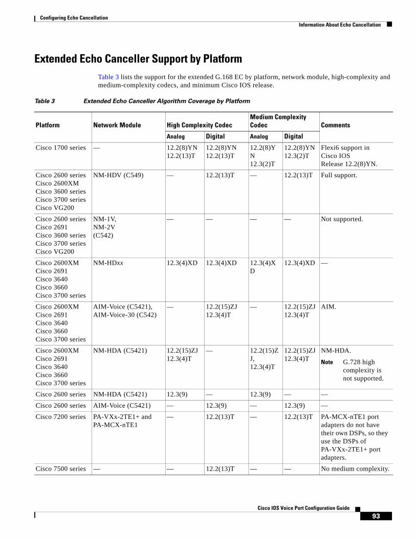
Configuring Echo Cancellation Information About Echo Cancellation
93Cisco IOS Voice Port Configuration Guide
Extended Echo Canceller Support by PlatformTable 3 lists the support for the extended G.168 EC by platform, network module, high-complexity and medium-complexity codecs, and minimum Cisco IOS release.
Table 3 Extended Echo Canceller Algorithm Coverage by Platform
Platform Network Module High Complexity CodecMedium Complexity Codec Comments
Analog Digital Analog Digital
Cisco 1700 series — 12.2(8)YN12.2(13)T
12.2(8)YN12.2(13)T
12.2(8)YN12.3(2)T
12.2(8)YN12.3(2)T
Flexi6 support in Cisco IOS Release 12.2(8)YN.
Cisco 2600 seriesCisco 2600XM Cisco 3600 seriesCisco 3700 series Cisco VG200
NM-HDV (C549) — 12.2(13)T — 12.2(13)T Full support.
Cisco 2600 seriesCisco 2691 Cisco 3600 seriesCisco 3700 series Cisco VG200
NM-1V, NM-2V(C542)
— — — — Not supported.
Cisco 2600XMCisco 2691Cisco 3640Cisco 3660Cisco 3700 series
NM-HDxx 12.3(4)XD 12.3(4)XD 12.3(4)XD
12.3(4)XD —
Cisco 2600XMCisco 2691Cisco 3640Cisco 3660Cisco 3700 series
AIM-Voice (C5421), AIM-Voice-30 (C542)
— 12.2(15)ZJ12.3(4)T
— 12.2(15)ZJ12.3(4)T
AIM.
Cisco 2600XMCisco 2691Cisco 3640Cisco 3660Cisco 3700 series
NM-HDA (C5421) 12.2(15)ZJ12.3(4)T
— 12.2(15)ZJ, 12.3(4)T
12.2(15)ZJ12.3(4)T
NM-HDA.
Note G.728 high complexity is not supported.
Cisco 2600 series NM-HDA (C5421) 12.3(9) — 12.3(9) — —
Cisco 2600 series AIM-Voice (C5421) — 12.3(9) — 12.3(9) —
Cisco 7200 series PA-VXx-2TE1+ and PA-MCX-nTE1
— 12.2(13)T — 12.2(13)T PA-MCX-nTE1 port adapters do not have their own DSPs, so they use the DSPs of PA-VXx-2TE1+ port adapters.
Cisco 7500 series — — 12.2(13)T — — No medium complexity.
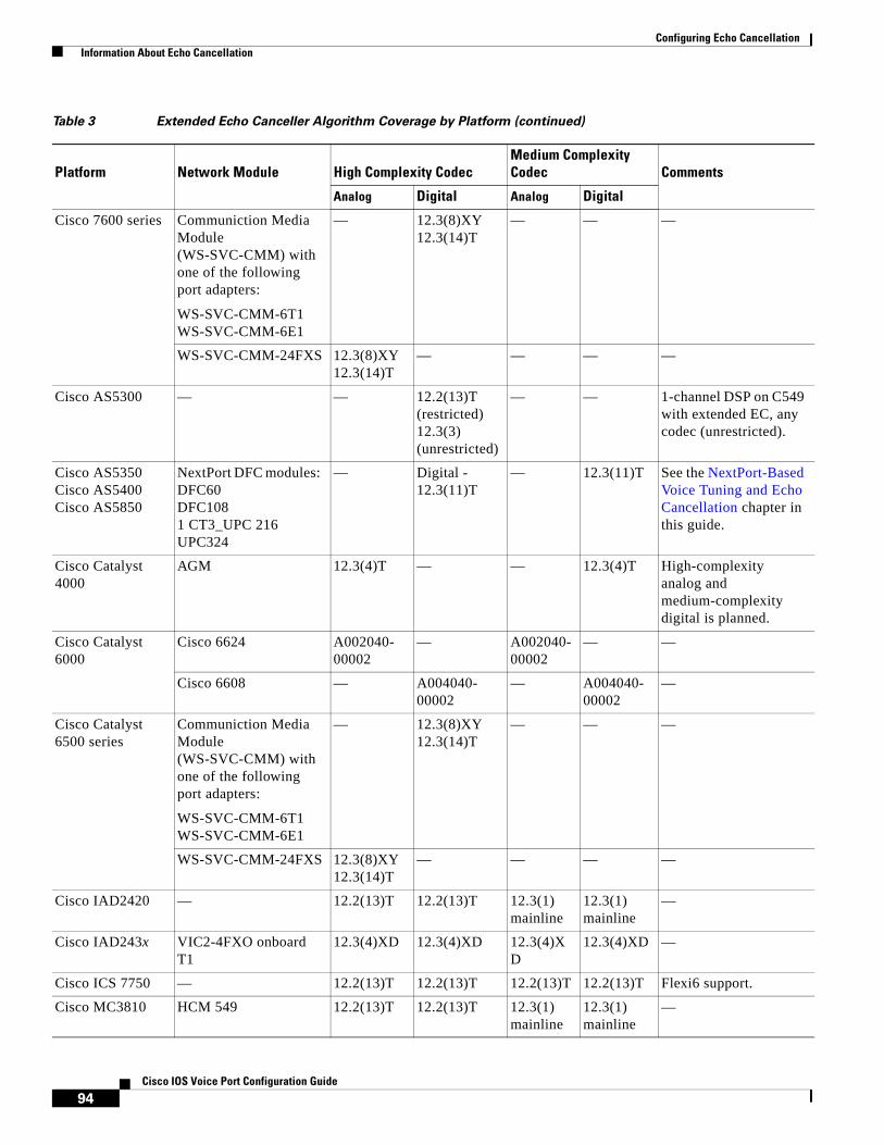
Configuring Echo Cancellation Information About Echo Cancellation
94Cisco IOS Voice Port Configuration Guide
Cisco 7600 series Communiction Media Module (WS-SVC-CMM) with one of the following port adapters:
WS-SVC-CMM-6T1WS-SVC-CMM-6E1
— 12.3(8)XY12.3(14)T
— — —
WS-SVC-CMM-24FXS 12.3(8)XY12.3(14)T
— — — —
Cisco AS5300 — — 12.2(13)T (restricted) 12.3(3) (unrestricted)
— — 1-channel DSP on C549 with extended EC, any codec (unrestricted).
Cisco AS5350Cisco AS5400Cisco AS5850
NextPort DFC modules: DFC60DFC1081 CT3_UPC 216UPC324
— Digital - 12.3(11)T
— 12.3(11)T See the NextPort-Based Voice Tuning and Echo Cancellation chapter in this guide.
Cisco Catalyst 4000
AGM 12.3(4)T — — 12.3(4)T High-complexity analog and medium-complexity digital is planned.
Cisco Catalyst 6000
Cisco 6624 A002040-00002
— A002040-00002
— —
Cisco 6608 — A004040-00002
— A004040-00002
—
Cisco Catalyst 6500 series
Communiction Media Module (WS-SVC-CMM) with one of the following port adapters:
WS-SVC-CMM-6T1WS-SVC-CMM-6E1
— 12.3(8)XY12.3(14)T
— — —
WS-SVC-CMM-24FXS 12.3(8)XY12.3(14)T
— — — —
Cisco IAD2420 — 12.2(13)T 12.2(13)T 12.3(1) mainline
12.3(1) mainline
—
Cisco IAD243x VIC2-4FXO onboard T1
12.3(4)XD 12.3(4)XD 12.3(4)XD
12.3(4)XD —
Cisco ICS 7750 — 12.2(13)T 12.2(13)T 12.2(13)T 12.2(13)T Flexi6 support.
Cisco MC3810 HCM 549 12.2(13)T 12.2(13)T 12.3(1) mainline
12.3(1) mainline
—
Table 3 Extended Echo Canceller Algorithm Coverage by Platform (continued)
Platform Network Module High Complexity CodecMedium Complexity Codec Comments
Analog Digital Analog Digital

Configuring Echo Cancellation How to Configure the Extended G.168 Echo Canceller
95Cisco IOS Voice Port Configuration Guide
How to Configure the Extended G.168 Echo CancellerThe Extended ITU-T standard G.168 Echo Cancellation feature provides an alternative to the default proprietary Cisco G.165 EC. Beginning in Release 12.4(20)T, the extended EC provides improved performance for trunking gateway applications and provides a configurable tail length that supports up to 128 ms of echo cancellation. The G.165 EC is not configurable in Cisco IOS Release 12.3(4)XD and later releases, except on the Cisco AS5300.
Note Extended echo cancellation is configured differently depending on the version of Cisco IOS software that you are using. If you are using Cisco IOS Release 12.3(4)XD or a later release, you do not have to use any Cisco IOS commands to enable the Extended ITU-T standard G.168 Echo Cancellation feature because the extended G.168 EC is the only available echo canceller. You have the option of disabling the extended EC, but it is highly recommended that you leave it enabled.
To configure the NextPort dual-filter G.168 echo canceller, see the NextPort-Based Voice Tuning and Echo Cancellation chapter in this guide.
This section contains the following procedures:
• Changing Echo Cancellers on Digital Voice Ports in Releases Prior to Cisco IOS Release 12.3(4)XD, page 96
• Configuring the Extended G.168 EC on the Cisco AS5300, page 98
• Modifying Echo Cancellation Default Settings, page 101
Table 4 lists the Cisco IOS commands that are used for selecting the extended G.168 EC based on your platform and Cisco IOS release.
Table 4 Cisco IOS Commands for Selecting Extended E.168 EC by Platform and Cisco IOS
Release
Cisco IOS Release Cisco IOS Command
Cisco 1700 Series and Cisco ICS 7750
12.2(13)T Router(config)# voice echo-canceller extended
12.2(13)ZH12.2(15)ZJ12.3(1)
Router(voice-card)# codec complexity medium
12.3(4)T and later No configuration necessary. G.168 EC enabled by default.
Cisco 2600 Series, Cisco 3600 Series, Cisco 3700 Series, Cisco MC3810, Cisco VG200
12.2(13)T12.2(13)ZH12.3(1)
Router(voice-card)# codec complexity medium ecan-extended
or
Router(voice-card)# codec complexity high ecan-extended
12.2(15)ZJ12.3(4)T
Router(voice-card)# codec complexity medium
12.3(4)XD and later No configuration necessary. G.168 EC enabled by default.
Cisco 7200 Series and Cisco 7500 Series
12.2(13)T Router(config-dspfarm)# codec complexity medium ecan-extended
12.2(13)ZH and later No configuration necessary. G.168 EC enabled by default.
Cisco 7600 Series with Communication Media Modules

Configuring Echo Cancellation Restrictions for G.168 Extended Echo Canceller
96Cisco IOS Voice Port Configuration Guide
Restrictions for G.168 Extended Echo Canceller• Not all Cisco platforms that use C542 or C549 DSPs support the extended EC.
• The G.168 extended EC is not supported on the Cisco AS5300 in Cisco IOS Release 12.2(13)ZH.
• The Cisco 1700 series does not support the T1/E1 card in Cisco IOS Release 12.2(13)T.
Changing Echo Cancellers on Digital Voice Ports in Releases Prior to Cisco IOS Release 12.3(4)XD
To use the G.168 extended EC in a release prior to Cisco IOS Release 12.3(4)XD, perform one of the following tasks depending on your hardware platform:
Cisco 1700 or Cisco ICS 7750
• Enabling the Extended G.168 EC on the Cisco 1700 Series and Cisco ICS 7750 in Cisco IOS Release 12.2(13)T, page 97
• Enabling the Extended G.168 EC on the Cisco 1700 Series and Cisco ICS 7750 in Cisco IOS Release 12.2(13)ZH, page 97
Cisco 2600 Series, Cisco 3600 Series, Cisco 3700 Series, Cisco MC3810, and Cisco VG200
• Changing Codec Complexity on Cisco 2600 Series, Cisco 3600 Series, Cisco 3700 Series, and Cisco MC3810 in the Con figuring Digital Voice Ports chapter.
Cisco 7200 Series and Cisco 7500 Series
• Configuring Codec Complexity on Cisco 7200 Series and Cisco 7500 Series Routers in the Configuring Digital Voice Ports chapter
Note See Table 3 for extended EC algorithm coverage by platform.
12.3(8)XY and later No configuration necessary. G.168 EC enabled by default.
Cisco AS5300
12.2(13)T Router(config)# voice echo-canceller extended codec small codec large codec
12.3(3) Router(config)# voice echo-canceller extended [codec small codec large codec]
Cisco Catalyst 6500 Series with Communication Media Modules
12.3(8)XY and later No configuration necessary. G.168 EC enabled by default.
Cisco Catalyst 4000 AGM
12.3(4)T and later No configuration necessary. G.168 EC enabled by default.
Table 4 Cisco IOS Commands for Selecting Extended E.168 EC by Platform and Cisco IOS
Release
Cisco IOS Release Cisco IOS Command

Configuring Echo Cancellation Restrictions for G.168 Extended Echo Canceller
97Cisco IOS Voice Port Configuration Guide
Enabling the Extended G.168 EC on the Cisco 1700 Series and Cisco ICS 7750 in Cisco IOS Release 12.2(13)T
To change codec complexity on the Cisco 1700 series and Cisco ICS 7750 and switch between the proprietary Cisco EC and the extended G.168 EC, use the following commands.
Note You must clear all calls on the system before using the following commands. If there are active calls on the system, the commands are ignored and a warning message is issued.
SUMMARY STEPS
1. enable
2. configure terminal
3. voice echo-canceller extended
4. exit
DETAILED STEPS
Enabling the Extended G.168 EC on the Cisco 1700 Series and Cisco ICS 7750 in Cisco IOS Release 12.2(13)ZH
The codec complexity medium command enables the extended echo canceller by default on the Cisco 1700 series and the Cisco ICS 7750 in Cisco IOS Release 12.2(13)ZH.
Command or Action Purpose
Step 1 enable
Example:Router> enable
Enables privileged EXEC mode.
• Enter your password if prompted.
Step 2 configure terminal
Example:Router# configure terminal
Enters global configuration mode.
Step 3 voice echo-canceller extended
Example:Router(config)# voice echo-canceller extended
Enables the G.168 extended echo canceller on the Cisco 1700 series or Cisco ICS 7750.
• You do not have to shut down all the voice ports on the Cisco 1700 or Cisco ICS 7750 to switch the echo canceller, but you should make sure that when you switch the echo canceller, there are no active calls on the router.
• To return to the proprietary Cisco G.165 default EC, use the no form of the command.
Step 4 exit
Example:Router(config)# exit
Exits global configuration mode.

Configuring Echo Cancellation Restrictions for G.168 Extended Echo Canceller
98Cisco IOS Voice Port Configuration Guide
Note You must clear all calls on the system before using the following commands. If there are active calls on the system, the commands are ignored and a warning message is issued.
SUMMARY STEPS
1. enable
2. configure terminal
3. voice-card slot
4. codec complexity {high | medium}
5. end
DETAILED STEPS
Configuring the Extended G.168 EC on the Cisco AS5300Perform this task to enable the Extended ITU-T standard G.168 Echo Cancellation feature on the Cisco AS5300. You must designate which EC to use on the Cisco AS5300 C542 and C549 DSPM high-complexity platform. You can use the extended EC with codec restrictions on the C542 DSP firmware or with or without codec restrictions on the C549 DSP firmware.
Command or Action Purpose
Step 1 enable
Example:Router> enable
Enables higher privilege levels, such as privileged EXEC mode.
• Enter your password if prompted.
Step 2 configure terminal
Example:Router# configure terminal
Enters global configuration mode.
Step 3 voice-card slot
Example:Router(config)# voice-card 1
Enters voice card configuration mode on the specified slot.
Step 4 codec complexity medium
Example:Router(voice-card)# codec complexity medium
Enables the extended EC (default).
Step 5 end
Example:Router(voice-card)# end
Exits voice-card configuration mode and completes the steps for configuring the extended EC on the Cisco 1700 series and Cisco ICS 7750.

Configuring Echo Cancellation Restrictions for G.168 Extended Echo Canceller
99Cisco IOS Voice Port Configuration Guide
Note A firmware upgrade can be made by upgrading Cisco VCWare. For upgrade information, refer to the Combined Version Release Notes and Compatibility Matrix for Cisco VCWare on Cisco AS5300 Universal Access Servers/Voice Gateways.
Prerequisites for Extended G.168 EC on Cisco AS5300
Extended EC with Restricted Codecs on C542 or C549 DSP
1. Create a backup of your router configuration.
2. Determine which codecs are required when enabling the extended echo canceller. For this information, see the codec restriction options for the voice echo-canceller extended command.
a. Specify a single small codec (g711 or g726) and a single large codec (g723, g728, GSM FR, GSM EFR, g729, or fax-relay). Any call setup involving other codecs is rejected.
b. If fax-relay is not selected as the large codec, the VoIP dial peer requires that you use the fax rate disabled command in dial-peer configuration mode to reset the dial peer for voice calls.
3. Review your existing configuration and look for all dial peers that select codecs or fax-relay specification that are different from the codecs that you decide on. After choosing the codecs to be supported by the extended echo canceller, either remove all dial peers with different codecs not supported by your new configuration or modify the dial-peer codec selection by selecting a voice codec or fax-relay that is supported by the new configuration.
4. Ensure that modem relay is not configured in any of the dial-peer configurations. If modem relay is configured, it should be disabled using the no modem relay command.
Extended EC with Unrestricted Codecs on C549 DSP
1. Create a backup of your router configuration.
2. Ensure that modem relay is not configured in any of the dial-peer configurations. If modem relay is configured, it should be disabled using the no modem relay command.
Restrictions for Extended G.168 EC on the Cisco AS5300
• The extended G.168 EC can be used only in one of the following ways on the Cisco AS5300:
– With a restricted set of codecs with C542 or C549 DSP firmware. Two channels of voice are supported per DSP, and full call handling capacity is supported.
– With no restrictions on codecs with C549 DSP firmware. One channel of voice is supported per DSP, and call handling capacity is reduced by half.
• Not all Cisco platforms that use C542 or C549 DSPs support the extended EC. Other platforms continue to use the proprietary Cisco G.165 EC if they do not support the extended EC.
SUMMARY STEPS
1. enable
2. configure terminal
3. no dial-peer voice tag voip
4. dial-peer voice tag voip
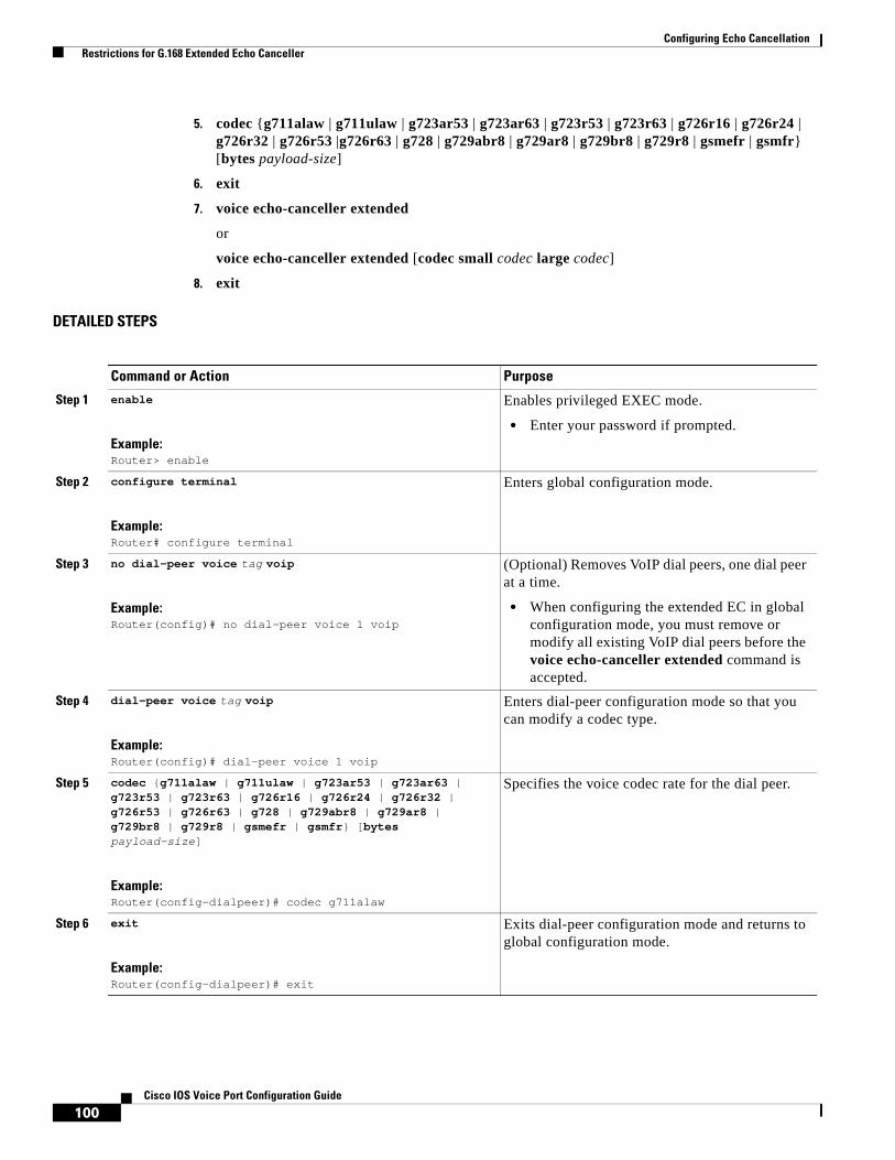
Configuring Echo Cancellation Restrictions for G.168 Extended Echo Canceller
100Cisco IOS Voice Port Configuration Guide
5. codec {g711alaw | g711ulaw | g723ar53 | g723ar63 | g723r53 | g723r63 | g726r16 | g726r24 | g726r32 | g726r53 |g726r63 | g728 | g729abr8 | g729ar8 | g729br8 | g729r8 | gsmefr | gsmfr} [bytes payload-size]
6. exit
7. voice echo-canceller extended
or
voice echo-canceller extended [codec small codec large codec]
8. exit
DETAILED STEPS
Command or Action Purpose
Step 1 enable
Example:Router> enable
Enables privileged EXEC mode.
• Enter your password if prompted.
Step 2 configure terminal
Example:Router# configure terminal
Enters global configuration mode.
Step 3 no dial-peer voice tag voip
Example:Router(config)# no dial-peer voice 1 voip
(Optional) Removes VoIP dial peers, one dial peer at a time.
• When configuring the extended EC in global configuration mode, you must remove or modify all existing VoIP dial peers before the voice echo-canceller extended command is accepted.
Step 4 dial-peer voice tag voip
Example:Router(config)# dial-peer voice 1 voip
Enters dial-peer configuration mode so that you can modify a codec type.
Step 5 codec {g711alaw | g711ulaw | g723ar53 | g723ar63 | g723r53 | g723r63 | g726r16 | g726r24 | g726r32 | g726r53 | g726r63 | g728 | g729abr8 | g729ar8 | g729br8 | g729r8 | gsmefr | gsmfr} [bytes payload-size]
Example:Router(config-dialpeer)# codec g711alaw
Specifies the voice codec rate for the dial peer.
Step 6 exit
Example:Router(config-dialpeer)# exit
Exits dial-peer configuration mode and returns to global configuration mode.
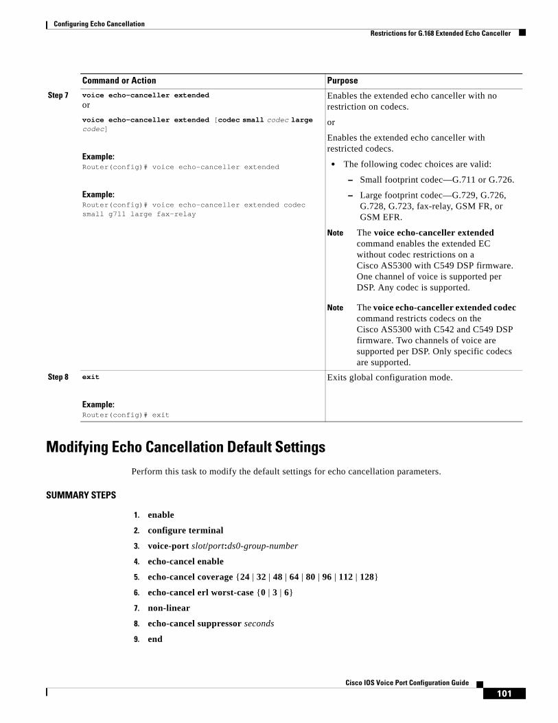
Configuring Echo Cancellation Restrictions for G.168 Extended Echo Canceller
101Cisco IOS Voice Port Configuration Guide
Modifying Echo Cancellation Default SettingsPerform this task to modify the default settings for echo cancellation parameters.
SUMMARY STEPS
1. enable
2. configure terminal
3. voice-port slot/port:ds0-group-number
4. echo-cancel enable
5. echo-cancel coverage {24 | 32 | 48 | 64 | 80 | 96 | 112 | 128}
6. echo-cancel erl worst-case {0 | 3 | 6}
7. non-linear
8. echo-cancel suppressor seconds
9. end
Step 7 voice echo-canceller extended
or
voice echo-canceller extended [codec small codec large codec]
Example:Router(config)# voice echo-canceller extended
Example:Router(config)# voice echo-canceller extended codec small g711 large fax-relay
Enables the extended echo canceller with no restriction on codecs.
or
Enables the extended echo canceller with restricted codecs.
• The following codec choices are valid:
– Small footprint codec—G.711 or G.726.
– Large footprint codec—G.729, G.726, G.728, G.723, fax-relay, GSM FR, or GSM EFR.
Note The voice echo-canceller extended command enables the extended EC without codec restrictions on a Cisco AS5300 with C549 DSP firmware. One channel of voice is supported per DSP. Any codec is supported.
Note The voice echo-canceller extended codec command restricts codecs on the Cisco AS5300 with C542 and C549 DSP firmware. Two channels of voice are supported per DSP. Only specific codecs are supported.
Step 8 exit
Example:Router(config)# exit
Exits global configuration mode.
Command or Action Purpose

Configuring Echo Cancellation Restrictions for G.168 Extended Echo Canceller
102Cisco IOS Voice Port Configuration Guide
DETAILED STEPS
Command or Action Purpose
Step 1 enable
Example:Router> enable
Enables higher privilege levels, such as privileged EXEC mode.
• Enter your password if prompted.
Step 2 configure terminal
Example:Router# configure terminal
Enters global configuration mode.
Step 3 voice-port slot/port:ds0-group-number
Example:Router(config)# voice-port 1/0:0
Enters voice-port configuration mode on the selected slot, port, and DS0 group.
Note The syntax of this command is platform-specific. For the syntax for your platform, refer to the Cisco IOS Voice Command Reference.
Step 4 echo-cancel enable
Example:Router(config-voiceport)# echo-cancel enable
Enables echo cancellation.
• Echo cancellation is enabled by default. Use the no form of this command to disable echo cancellation.
• The extended G.168 EC is the default EC for all supported platforms in Cisco IOS Release 12.3(4)XD and later releases, except the Cisco AS5300.
• On the Cisco AS5300, the Cisco G.165 EC is enabled by default with echo suppression disabled.
Note This command is supported only when the echo-cancel coverage command is enabled.
Step 5 echo-cancel coverage {24 | 32 | 48 | 64 | 80 | 96 | 112 | 128}
Example:Router(config-voiceport)# echo-cancel coverage 64
Adjusts the size of the echo canceller (echo path capacity coverage).
• 128 is the default in Cisco IOS Release 12.4(20)T and later releases. Prior to this release, the default is 64 ms.
Note This command is supported only when echo cancellation is enabled. See Step 4 of this procedure.

Configuring Echo Cancellation Restrictions for G.168 Extended Echo Canceller
103Cisco IOS Voice Port Configuration Guide
Step 6 echo-cancel erl worst-case [0 | 3 | 6]
Example:Router(config-voiceport)# echo-cancel erl worst-case 6
(Optional) Determines worst-case ERL in dB.
• Worst-case ERL is the minimum expected attenuation in the voice path. For example, if you have a worst-case ERL of 6 (erl worst-case 6), when you speak into the phone you can expect at least 6 dB of attenuation on the signal by the time it gets back to the original source (echo). In general you do not need to change this value from 6, which is the default.
Worst-case ERL does not directly modify the inbound or outbound signals. This is purely a configuration parameter for the EC to help it distinguish between echo and a new signal.
Note This command is supported for the extended G.168 EC only; it is not supported for the G.165 EC.
Step 7 non-linear
Example:Router(config-voiceport)# non-linear
(Optional) Selects nonlinear processing (residual echo suppression) in the EC, which either shuts off any signal or mixes in comfort noise if no near-end speech is detected.
Note This command is supported only when echo cancellation is enabled. See Step 4.
• Nonlinear processing is enabled when the extended G.168 EC is enabled. Use the no form of this command to disable the NLP.
Command or Action Purpose

Configuring Echo Cancellation Configuration Examples for Extended G.168 Echo Cancellation
104Cisco IOS Voice Port Configuration Guide
Configuration Examples for Extended G.168 Echo CancellationThis section includes the following examples:
• Enabling the Extended EC on the Cisco 7200 Series or Cisco 7500 Series: Example, page 106
• Enabling the Extended Echo Canceller on the Cisco 2600 Series, Cisco 3600 Series, Cisco 3700 Series, and Cisco VG200 in Releases Prior to Cisco IOS Release 12.3(4)XD: Example, page 105
• Enabling the Extended EC on the Cisco 7200 Series or Cisco 7500 Series: Example, page 106
• Enabling the Extended Echo Canceller on the Cisco AS5300: Example, page 106
• Adjusting the Echo Canceller Size: Example, page 107
• Worst-Case Echo Return Loss: Example, page 107
Step 8 echo-cancel suppressor seconds
Example:Router(config-voiceport)# echo-cancel suppressor 10
(Optional) Applies echo suppression for the number of seconds specified when using the G.165 EC.
• This command cannot be used with the extended G.168 EC in Cisco IOS Release 12.2(15)ZJ or later releases, or on NextPort (Cisco AS5350 and Cisco AS5400) platforms.
Note This command is required to configure the Extended ITU-T standard G.168 Echo Cancellation feature in Cisco IOS Release 12.2(13)T.
• For the AS5300, the Cisco G.165 EC is enabled by default with echo suppression disabled. The echo suppressor can be used only on T1 DSPs when the default Cisco G.165 EC is used.
• This command enables echo cancellation for voice that is sent out an interface and received back on the same interface within the configured amount of time.
• This command reduces the initial echo before the echo canceller can converge. In case of double-talk in the first number of seconds, the code automatically disables the suppressor.
• The echo-cancel suppressor command is visible when the G.168 extended EC is selected but it has no effect.
Note This command is supported only when echo cancellation is enabled.
Step 9 end
Example:Router(config-voiceport)# end
Exits voice-port configuration mode and completes the configuration.
Command or Action Purpose
Configuring Echo Cancellation Configuration Examples for Extended G.168 Echo Cancellation
105Cisco IOS Voice Port Configuration Guide
Enabling the Extended EC on the Cisco 1700 Series and Cisco ICS 7750: ExampleThe following example enables the G.168 extended EC on a Cisco 1700 series or a Cisco ICS 7750. The extended EC is enabled by default when the medium keyword is used in Cisco IOS Release 12.2(13)ZH and later.
voice-card 1 codec complexity medium
Enabling the Extended Echo Canceller on the Cisco 2600 Series, Cisco 3600 Series, Cisco 3700 Series, and Cisco VG200 in Releases Prior to Cisco IOS Release 12.3(4)XD: Example
The following example shows that the echo canceller has been changed from the default proprietary Cisco EC to the extended EC in Cisco IOS releases prior to 12.3(4)XD.
Note The extended G.168 EC is the only EC in Cisco IOS Release 12.3(4)XD and later releases. Because it is enabled by default, it does not display in the configuration output in Cisco IOS Release 12.3(4)XD and later releases.
The following is example output from an originating Cisco 3640:
.
.
.voice-card 1 codec complexity high ecan-extended...controller T1 1/0 framing esf linecode b8zs pri-group timeslots 1-24!voice-port 1/0:23...dial-peer voice 104001 voip destination-pattern 104001 session target ipv4:10.2.0.104 dtmf-relay cisco-rtp codec g711alaw fax rate 14400 fax protocol cisco...
Configuring Echo Cancellation Configuration Examples for Extended G.168 Echo Cancellation
106Cisco IOS Voice Port Configuration Guide
Enabling the Extended EC on the Cisco 7200 Series or Cisco 7500 Series: Example
The following example changes codec complexity on a Cisco 7200 series or 7500 series:
dspint dspfarm 2/0 codec medium ecan-extended
Enabling the Extended Echo Canceller on the Cisco AS5300: Example
The following example enables the extended G.168 EC with restricted codecs on the Cisco AS5300 with C542 or C549 DSP firmware:
!version 12.3no service padservice timestamps debug datetime msecservice timestamps log uptimeno service password-encryptionservice internal!hostname router!boot-start-markerboot-end-marker!enable secret 5 $123enable password temp!!resource-pool disable!no aaa new-modelip subnet-zeroip rcmd rcp-enableip rcmd rsh-enableip domain name cisco.comip host router1 10.10.101.14!!isdn switch-type primary-5ess!voice echo-canceller extended codec small g711 large fax-relay!!!fax interface-type fax-mail!!controller T1 0 framing esf clock source line primary linecode b8zs pri-group timeslots 1-24...
Configuring Echo Cancellation Configuration Examples for Extended G.168 Echo Cancellation
107Cisco IOS Voice Port Configuration Guide
Adjusting the Echo Canceller Size: Example
The following example adjusts the size of the extended EC to 64 ms on Cisco 3600 series routers:
voice-port 1/0:0 echo-cancel coverage 64
Worst-Case Echo Return Loss: Example
The following example sets the worst-case echo return loss to 3:
voice-port 0:D echo-canceller erl worst-case 3 playout-delay mode fixed no comfort-noise
CCDE, CCENT, Cisco Eos, Cisco Lumin, Cisco Nexus, Cisco StadiumVision, the Cisco logo, DCE, and Welcome to the Human Network are trademarks; Changing the Way We Work, Live, Play, and Learn is a service mark; and Access Registrar, Aironet, AsyncOS, Bringing the Meeting To You, Catalyst, CCDA, CCDP, CCIE, CCIP, CCNA, CCNP, CCSP, CCVP, Cisco, the Cisco Certified Internetwork Expert logo, Cisco IOS, Cisco Press, Cisco Systems, Cisco Systems Capital, the Cisco Systems logo, Cisco Unity, Collaboration Without Limitation, EtherFast, EtherSwitch, Event Center, Fast Step, Follow Me Browsing, FormShare, GigaDrive, HomeLink, Internet Quotient, IOS, iPhone, iQ Expertise, the iQ logo, iQ Net Readiness Scorecard, iQuick Study, IronPort, the IronPort logo, LightStream, Linksys, MediaTone, MeetingPlace, MGX, Networkers, Networking Academy, Network Registrar, PCNow, PIX, PowerPanels, ProConnect, ScriptShare, SenderBase, SMARTnet, Spectrum Expert, StackWise, The Fastest Way to Increase Your Internet Quotient, TransPath, WebEx, and the WebEx logo are registered trademarks of Cisco Systems, Inc. and/or its affiliates in the United States and certain other countries.
All other trademarks mentioned in this document or Website are the property of their respective owners. The use of the word partner does not imply a partnership relationship between Cisco and any other company. (0805R)
Any Internet Protocol (IP) addresses used in this document are not intended to be actual addresses. Any examples, command display output, and figures included in the document are shown for illustrative purposes only. Any use of actual IP addresses in illustrative content is unintentional and coincidental.
© 2008 Cisco Systems, Inc. All rights reserved.

Configuring Echo Cancellation Configuration Examples for Extended G.168 Echo Cancellation
108Cisco IOS Voice Port Configuration Guide

Americas Headquarters:Cisco Systems, Inc., 170 West Tasman Drive, San Jose, CA 95134-1706 USA
© 2008 Cisco Systems, Inc. All rights reserved.
Configuring Hardware Echo Cancellation on T1/E1 Multiflex Voice/WAN Interface Cards
The multiflex trunk (MFT) dedicated echo cancellation modules (dedicated ECAN modules) are daughter cards that attach to the second generation multiflex voice/WAN interface cards (MFT VWIC2 family). The dedicated ECAN modules are available in 32-channel and 64-channel configurations (EC-MFT-32 and EC-MFT-64), which match the requirements of the 1- and 2-port T1/E1 MFT VWIC2s, respectively. This chapter describes the configuration to enable additional echo cancellation effectiveness:
• Control of the echo canceller provided through the size of the echo cancellation buffer, ranging from 24 milliseconds (ms) to 128 ms
• Processing and memory resources to ensure robust echo canceller coverage independent from the configuration of the echo canceller or the demand placed on the general voice DSP resources
Prerequisites for Hardware Echo Cancellation on T1/E1 Multiflex Voice/WAN Interface Cards
Cisco IOS ImageTo run hardware echo cancellation on T1/E1 interfaces, you must install an IP Plus or IP Voice image (minimum) of Cisco IOS Release 12.3(14)T or a later release.
Baseboard and Daughter Card ConfigurationHardware echo cancellation is restricted to the same baseboard voice/WAN interface card (VWIC) on which the daughter card (EC-MFT-32 and EC-MFT-64) is installed and cannot be shared by other T1/E1 controllers.

Configuring Hardware Echo Cancellation on T1/E1 Multiflex Voice/WAN Interface Cards Information About Hardware Echo Cancellation on T1/E1 Multiflex Voice/WAN Interface Cards
110Cisco IOS Voice Port Configuration Guide
Hardware Echo Cancellation Tail LengthIf you are using hardware echo cancellation, the value for tail length is set to 128 ms. This is not configurable and cannot be changed.
Information About Hardware Echo Cancellation on T1/E1 Multiflex Voice/WAN Interface Cards
Table 1 lists the names and descriptions of the baseboard modules and daughter cards that offer hardware echo cancellation on T1/E1 multiflex voice/WAN interface cards.
Figure 1 shows a sample network topology with a Cisco 3725 router using hardware echo cancellation.
Table 1 Modules with T1/E1 Multiflex Voice/WAN Interface Cards with Echo Cancellation
Functionality
Module Name Description
Baseboard VIC2-1MFT-T1/E11
1. The VIC2-1MFT-T1/E1 and VIC2-2MFT-T1/E1 voice modules do not support WAN connectivity.
1-port RJ-48 multiflex voice trunk (T1/E1)
VIC2-2MFT-T1/E11 2-port RJ-48 multiflex voice trunk (T1/E1)
VWIC2-1MFT-T1/E1 1-port RJ-48 multiflex voice/WAN trunk (T1/E1)
VWIC2-2MFT-T1/E1 2-port RJ-48 multiflex voice/WAN trunk (T1/E1)
VWIC2-1MFT-G7032
2. Although unstructured G.703 operation is particular to E1 operation, the VWIC2-1/2MFT-G703 cards also support structured T1 operation.
1-port RJ-48 multiflex trunk (E1 G.703)
VWIC2-2MFT-G7032 2-port RJ-48 multiflex trunk (E1 G.703)
Daughter cards for hardware echo cancellation
EC-MFT-32 32-channel echo canceller module for multiflex trunk
EC-MFT-64 64-channel echo canceller module for multiflex trunk
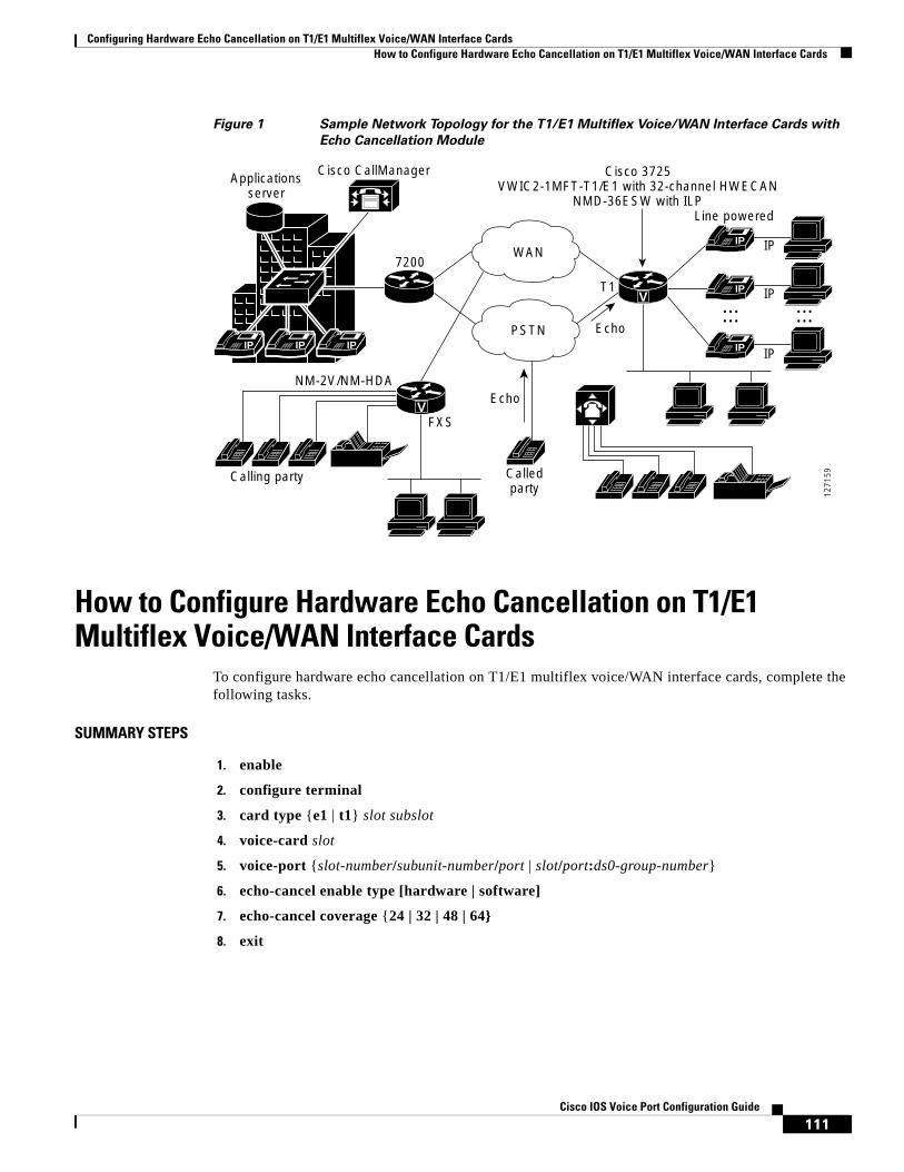
Configuring Hardware Echo Cancellation on T1/E1 Multiflex Voice/WAN Interface Cards How to Configure Hardware Echo Cancellation on T1/E1 Multiflex Voice/WAN Interface Cards
111Cisco IOS Voice Port Configuration Guide
Figure 1 Sample Network Topology for the T1/E1 Multiflex Voice/WAN Interface Cards with
Echo Cancellation Module
How to Configure Hardware Echo Cancellation on T1/E1 Multiflex Voice/WAN Interface Cards
To configure hardware echo cancellation on T1/E1 multiflex voice/WAN interface cards, complete the following tasks.
SUMMARY STEPS
1. enable
2. configure terminal
3. card type {e1 | t1} slot subslot
4. voice-card slot
5. voice-port {slot-number/subunit-number/port | slot/port:ds0-group-number}
6. echo-cancel enable type [hardware | software]
7. echo-cancel coverage {24 | 32 | 48 | 64}
8. exit
V
Applicationsserver
Cisco CallManager
7200
T1
FXS
NM-2V/NM-HDA
Calling party Calledparty 12
7159
IP IP IPIP IP
IP
IP
IPIP
V
PSTN Echo
Echo
Cisco 3725VWIC2-1MFT-T1/E1 with 32-channel HWECAN
NMD-36ESW with ILPLine powered
IP
IP
IP
WAN
...... ......
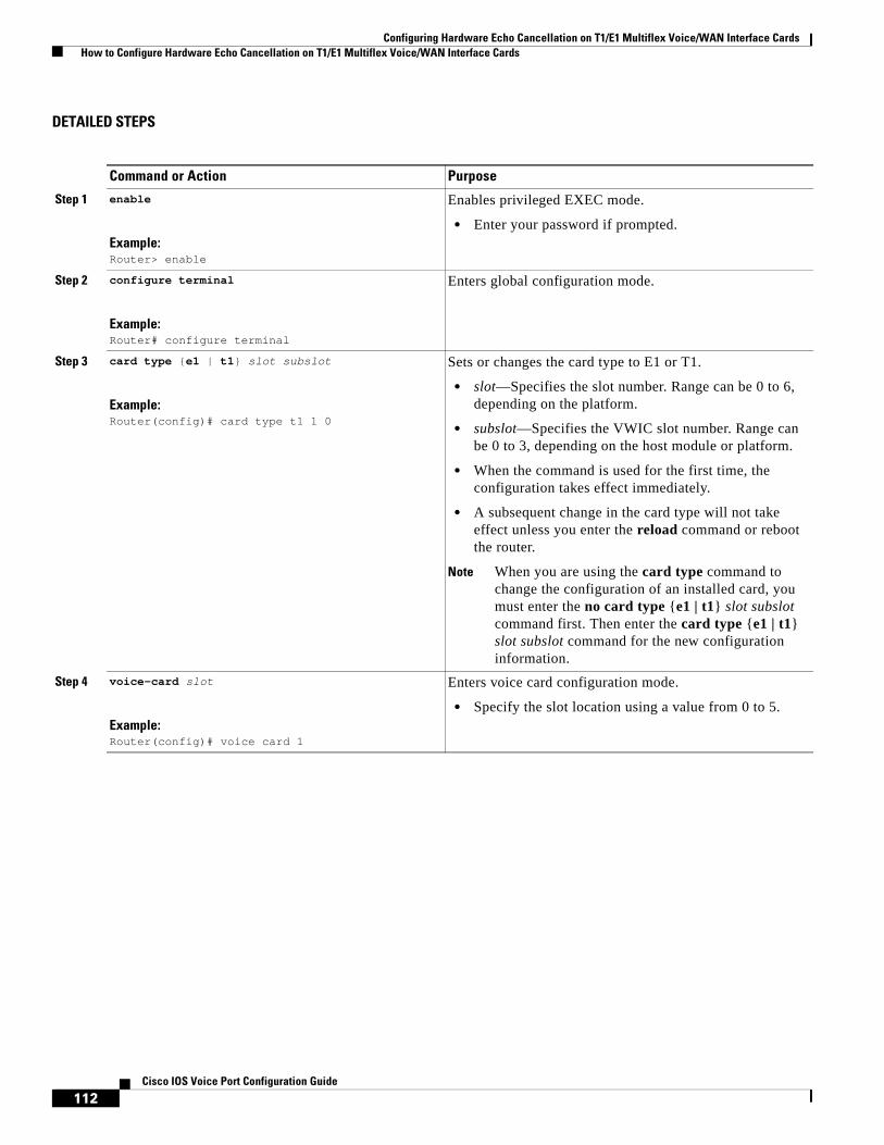
Configuring Hardware Echo Cancellation on T1/E1 Multiflex Voice/WAN Interface Cards How to Configure Hardware Echo Cancellation on T1/E1 Multiflex Voice/WAN Interface Cards
112Cisco IOS Voice Port Configuration Guide
DETAILED STEPS
Command or Action Purpose
Step 1 enable
Example:Router> enable
Enables privileged EXEC mode.
• Enter your password if prompted.
Step 2 configure terminal
Example:Router# configure terminal
Enters global configuration mode.
Step 3 card type {e1 | t1} slot subslot
Example:Router(config)# card type t1 1 0
Sets or changes the card type to E1 or T1.
• slot—Specifies the slot number. Range can be 0 to 6, depending on the platform.
• subslot—Specifies the VWIC slot number. Range can be 0 to 3, depending on the host module or platform.
• When the command is used for the first time, the configuration takes effect immediately.
• A subsequent change in the card type will not take effect unless you enter the reload command or reboot the router.
Note When you are using the card type command to change the configuration of an installed card, you must enter the no card type {e1 | t1} slot subslot command first. Then enter the card type {e1 | t1} slot subslot command for the new configuration information.
Step 4 voice-card slot
Example:Router(config)# voice card 1
Enters voice card configuration mode.
• Specify the slot location using a value from 0 to 5.

Configuring Hardware Echo Cancellation on T1/E1 Multiflex Voice/WAN Interface Cards How to Configure Hardware Echo Cancellation on T1/E1 Multiflex Voice/WAN Interface Cards
113Cisco IOS Voice Port Configuration Guide
Step 5 voice-port {slot-number/subunit-number/port | slot/port:ds0-group-number}
Example:Router(voice-card)# voice-port 3/0:0
Enters voice port configuration mode and specifies the voice port.
• The slot-number argument identifies the slot where the voice interface card (VIC) is installed. Valid entries are from 0 to 3, depending on the slot in which it has been installed.
• The subunit-number identifies the subunit on the VIC where the voice port is located. Valid entries are 0 or 1.
• The port argument identifies the voice port number. Valid entries are 0 and 1.
or
• The slot argument is the slot in which the voice port adapter is installed. Valid entries are from 0 to 3.
• The port argument is the voice interface card location. Valid entries are 0 to 3.
• The ds0-group-number argument indicates the defined DS0 group number. Each defined DS0 group number is represented on a separate voice port. This allows you to define individual DS0s on the digital T1/E1 card.
Note The commands, keywords, and arguments that you are able to use may differ slightly from those presented here, based on your platform, Cisco IOS release, and configuration. When in doubt, use Cisco IOS command help to determine the syntax choices that are available.
Step 6 echo-cancel enable type [hardware | software]
Example:router(config-voiceport)# echo-cancel enable type hardware
Enables hardware echo cancellation.
• The hardware keyword is the default. Echo cancel coverage is hardcoded for 128 ms.
• This command is needed only to configure the software keyword to effect software-based (DSP) echo cancellation or to restore the hardware default.
Note The hardware and software keywords are available only when the optional hardware echo cancellation module (EC-MFT-32 or EC-MFT-64) is installed on the multiflex VWIC.
Command or Action Purpose

Configuring Hardware Echo Cancellation on T1/E1 Multiflex Voice/WAN Interface Cards How to Configure Hardware Echo Cancellation on T1/E1 Multiflex Voice/WAN Interface Cards
114Cisco IOS Voice Port Configuration Guide
Examples
This section provides the following examples for verifying echo cancellation:
• show echo-cancel hardware status: Example, page 114
• show call active voice echo-canceller summary: Example, page 114
• show call active voice echo-canceller CallID: Example, page 115
show echo-cancel hardware status: Example
The output in this section shows that hardware echo cancellation is enabled on slot 1.
Router_3725# show echo-cancel hardware status 1 VWIC HWECAN 1/0 is UP.Software version:4.4.803 , Date:Feb 6 16:58:57 2004Tail length:128 Tone disabler type:G.165 Fax notify: OffDevice:VWIC_8MBPS_1TIEC_TL128_MS_1P Max Channels:32Only Port0 have Local HWECAN Connectivity.
Total assigned channel(s):1Total device(s) in the slot 1
show call active voice echo-canceller summary: Example
The output in this section shows summary information for the hardware echo cancellation.
Router_3725# show call active voice echo-canceller summary
Step 7 echo-cancel coverage {24 | 32 | 48 | 64 | 80 | 96 | 112 | 128}
Example:Router (config-voiceport) # echo-cancel coverage 96
Adjusts the echo canceller by the specified number of milliseconds.
• These coverage options are applicable only if you configured the echo-cancel enable type software command in the previous step.
• If you configured the echo-cancel enable type hardware command in the previous step, this value is set to 128 ms.
• Beginning with Release 12.4(20)T, the default for software echo cancellation is 128 ms. Prior to Release 12.4(20)T, the default is 64 ms.
Step 8 exit
Example:Router(config-voiceport)# exit
Exits controller cofiguration mode and returns the router to privileged EXEC mode.
Command or Action Purpose
ECAN CH ASSIGNED DSP ID VOICEPORT EC NLP COV LAW
========================================================================================
1 yes 1/1 1/0:1.1 on off on u-Law

Configuring Hardware Echo Cancellation on T1/E1 Multiflex Voice/WAN Interface Cards How to Configure Hardware Echo Cancellation on T1/E1 Multiflex Voice/WAN Interface Cards
115Cisco IOS Voice Port Configuration Guide
1 active call foundnumber of hardware ecan channels:1number of software ecan channels:0
show call active voice echo-canceller CallID: Example
The output in this section shows hardware echo canceller information for an active voice call.
Router# show call active voice echo-canceller E71 Device:VWIC HWECAN 1/0 Channel Id = 1 Tail = 128MsSoftware version:4.4.803 , Date:Feb 6 16:58:57 2004 Echo Canceller:On Tail-length:128ms H-Register:Update Modem tone disable:Ignore 2100Hz tone Worst ERL :6dB Residual Control:Cancel only High level compensation:Off Tx Power = 0.0dB Tx Avg Power = 0.0dB Rx Power = 0.0dB Rx Avg Power = 0.0dB ERL = 1.0dB ACOM = 0.0 3 Reflectors(Tails) = (90, 0, 0)Ms, Max Reflector = 90Ms Ecan Status words 0x1C, 0x00 EC Lib version:9155
More detailed syntax information about the commands used in this chapter is documented in the Cisco IOS Voice Command Reference.
CCDE, CCENT, Cisco Eos, Cisco Lumin, Cisco Nexus, Cisco StadiumVision, the Cisco logo, DCE, and Welcome to the Human Network are trademarks; Changing the Way We Work, Live, Play, and Learn is a service mark; and Access Registrar, Aironet, AsyncOS, Bringing the Meeting To You, Catalyst, CCDA, CCDP, CCIE, CCIP, CCNA, CCNP, CCSP, CCVP, Cisco, the Cisco Certified Internetwork Expert logo, Cisco IOS, Cisco Press, Cisco Systems, Cisco Systems Capital, the Cisco Systems logo, Cisco Unity, Collaboration Without Limitation, EtherFast, EtherSwitch, Event Center, Fast Step, Follow Me Browsing, FormShare, GigaDrive, HomeLink, Internet Quotient, IOS, iPhone, iQ Expertise, the iQ logo, iQ Net Readiness Scorecard, iQuick Study, IronPort, the IronPort logo, LightStream, Linksys, MediaTone, MeetingPlace, MGX, Networkers, Networking Academy, Network Registrar, PCNow, PIX, PowerPanels, ProConnect, ScriptShare, SenderBase, SMARTnet, Spectrum Expert, StackWise, The Fastest Way to Increase Your Internet Quotient, TransPath, WebEx, and the WebEx logo are registered trademarks of Cisco Systems, Inc. and/or its affiliates in the United States and certain other countries.
All other trademarks mentioned in this document or Website are the property of their respective owners. The use of the word partner does not imply a partnership relationship between Cisco and any other company. (0805R)
Any Internet Protocol (IP) addresses used in this document are not intended to be actual addresses. Any examples, command display output, and figures included in the document are shown for illustrative purposes only. Any use of actual IP addresses in illustrative content is unintentional and coincidental.
© 2008 Cisco Systems, Inc. All rights reserved.
Call ID Port DSP/Ch Codec Ecan-type Tail Called # Dial-peers
========================================================================================
0xE71 1/0:1.1 1/1 g729r8 HW 128ms 1000 1/10

Configuring Hardware Echo Cancellation on T1/E1 Multiflex Voice/WAN Interface Cards How to Configure Hardware Echo Cancellation on T1/E1 Multiflex Voice/WAN Interface Cards
116Cisco IOS Voice Port Configuration Guide

Americas Headquarters:Cisco Systems, Inc., 170 West Tasman Drive, San Jose, CA 95134-1706 USA
© 2008 Cisco Systems, Inc. All rights reserved.
NextPort-Based Voice Tuning and Echo Cancellation
This chapter describes how to dynamically configure voice services on the NextPort-based platforms: Cisco AS5350, Cisco AS5400, Cisco AS5400HPX, and Cisco AS5850. This chapter contains the following sections:
• Prerequisites for Nextport-Based Voice Tuning and NextPort Dual-Filter G.168 Echo Canceller, page 117
• Information About NextPort Voice Services, page 117
• How to Configure Nextport-Based Voice Tuning and the NextPort Dual-Filter G.168 Echo Canceller, page 120
Prerequisites for Nextport-Based Voice Tuning and NextPort Dual-Filter G.168 Echo Canceller
To use the Nextport-Based Voice Tuning and Background Noise Statistics feature, you must be running NextPort service processing element (SPE) firmware version 8.8.1 or a later version and Cisco IOS Release 12.3(4)T or a later release.
To use the NextPort dual-filter G.168 echo canceller, you must be running SPE firmware version 10.2.2 or a later version and Cisco IOS Release 12.3(11)T or a later release.
Information About NextPort Voice Services To configure the features presented in this chapter, you should understand the following concepts:
• NextPort Dual-Filter G.168 Echo Canceller, page 118
• NextPort SPE Firmware, page 119
• Voice Tuning, page 119
• Background Noise, page 120

NextPort-Based Voice Tuning and Echo Cancellation Information About NextPort Voice Services
118Cisco IOS Voice Port Configuration Guide
NextPort Dual-Filter G.168 Echo CancellerThe CSMV6 dial feature card (DFC) for NextPort platforms offers dual-filter G.168 echo canceller capability. The NextPort dual-filter G.168 echo canceller (EC) improves voice quality in VoIP connections by providing relatively less residual echo leakage, better nonlinear processing (NLP) timing, less clipping, and better comfort noise generation (CNG) in most environments.
The dual-filter G.168 echo canceller features two concurrently operating adaptive filters (which control echo tail coverage) and two double-talk detection functions. In addition, the comfort noise model uses “Hoth noise” spectrum shaping to better replicate the true noise spectrum.
Note Detailed information for all Cisco IOS commands mentioned in this section can be found in the Cisco IOS Voice Command Reference.
The NextPort dual-filter G.168 echo canceller uses the same voice-tuning (VC tune) interface for configuring voicecap parameters as the Cisco-proprietary G.164 echo canceller. To adjust the dual-filter echo canceller, use a voicecap or the Cisco IOS command-line interface (CLI) during configuration. You can also adjust settings while the system is running by using the show port log and show port operational-status commands. However because of the differences in internal operation of these ECs, there are some changes in the set of available parameters for voice tuning.
See the echo-cancel coverage command for updated Cisco IOS command usage with this feature. The NextPort dual-filter G.168 echo canceller adds the following benefits on NextPort platforms:
• Configurable parameters—Range checking that is performed on the voicecap parameters in the I960 NextPort layer has been updated. (Voicecap parameters in “raw mode” are never range-checked.)
• Up to 128 ms of echo tail coverage—Beginning with Cisco IOS Release 12.4(20)T, the NextPort dual-filter G.168 echo canceller supports echo tails from 24-ms to 128-ms in 16-ms increments. The echo-cancel coverage command limits the echo canceller coverage to 128-ms on NextPort platforms. For backward compatibility, a voicecap used in "raw mode" will still configure older SPEware to settings greater than 64-ms when used with newer releases of Cisco IOS software. For situations when new SPEware is loaded onto an older Cisco IOS release, the NextPort dual-filter G.168 echo canceller automatically sets coverage time to 64 ms.
• Updated set of reported statistics—Text in the show voice port command output has been changed to describe voicecap parameters and reported statistics. The show port operational-status command output has been updated to report TX/RX mean speech level statistics.
• Power statistics (RX and TX)—These statistics average only the power that is received during signal periods that are classified as speech.
• Unchanged configuration steps—Use voicecaps and the echo-cancel coverage command to configure this feature. See the “Voicecap Strings” section on page 119.
• SPE firmware and Cisco IOS software packaging support—The SPEware that contains the dual-filter G.168 echo canceller is field-upgradeable and can be used interchangeably with previous firmware versions with no effect on platform call density. The new SPEware interoperates with any Cisco IOS software release that supports voicecaps.
Note When older Cisco IOS software releases are used, voicecaps must be used in raw mode for some parameters. Some statistics may not be displayed or recorded properly with older software releases.
NextPort-Based Voice Tuning and Echo Cancellation Information About NextPort Voice Services
119Cisco IOS Voice Port Configuration Guide
NextPort SPE FirmwareNextPort SPE firmware is software that drives the digital signal processor (DSP) portion of the NextPort dial feature cards (DFCs). NextPort firmware is bundled with Cisco IOS software.
NextPort SPE firmware runs on the NextPort DFC60, DFC108, 1 CT3_UPC 216, and UPC324 DFCs on the Cisco AS5350, Cisco AS5400, Cisco AS5400HPX, and Cisco AS5850 platforms. The ports on these modules can support modem, voice, fax, and digital services and can be aggregated at any of the following levels:
• Slot level of the NextPort module
• SPE level within the NextPort module
• Individual port level
Note To use the NextPort Voice Tuning and Background Noise Statistics feature, you must use the default bundled NextPort SPE firmware code that runs with Cisco IOS software. The NextPort-Based Voice Tuning and Background Noise feature uses SPE firmware version 8.8.1 or a later version. The NextPort dual-filter G.168 echo canceller uses NextPort firmware version 10.2.2, which is bundled with Cisco IOS Release 12.3(11)T. NextPort firmware version 10.2.2 can be used with Cisco IOS Release 12.3(7)T, 12.3(10), and later releases.
For more information about NextPort SPE firmware, see the NextPort SPE Release Notes on Cisco.com.
Voicecap Strings
Additional configuration of voice services on NextPort DFCs is achieved by configuring the voice tuning configuration capability (called voicecaps) using voicecap strings. Voicecap strings are created with the the voicecap entry command and are applied with the voicecap configure command.
Voice Tuning
Note You must have specific knowledge of the behavior of the telephone network in order to use these voicecap capabilities. See the Nextport-Based Voice Tuning White Paper on Cisco.com for a brief description of telephone network behavior.
This feature allows the following parameters, among others, to be configured:
• PSTN gains—PSTN gains adjust the power levels at the PSTN side of a VoIP connection to make up for loss plan imbalances and to ensure minimum echo return losses (ERLs) in a call. PSTN gain is configured with the CLI rather than with voicecaps.
• IP gains—IP gains adjust IP-side levels and are applied to the signal before it is propagated through the echo canceller. This point is also known as the reference signal.
• Dynamic attenuation—Dynamic attenuation mitigates low volume calls when attenuation has been added on the PSTN call leg to compensate for low ERL calls.
• Comfort noise generation—CNG enables and disables EC comfort noise.
• Minimum ERL—Minimum ERL switches off near-end talker clipping and poor echo canceller performance.

NextPort-Based Voice Tuning and Echo Cancellation How to Configure Nextport-Based Voice Tuning and the NextPort Dual-Filter G.168 Echo Canceller
120Cisco IOS Voice Port Configuration Guide
Background NoiseThe NextPort Voice Tuning and Background Noise Statistics feature reports EC background noise level, voice activity detection (VAD) background noise level, ERL level, and Acombined (ACOM) statistics by averaging the combined values that are computed over the duration of the call. These statistics are appended to the end of each entry in the voice log, which you can see in the output from the show port log and show port operational-status commands.
How to Configure Nextport-Based Voice Tuning and the NextPort Dual-Filter G.168 Echo Canceller
To configure the Nextport-Based Voice Tuning and the NextPort Dual-Filter G.168 Echo Canceller feature, complete the following tasks:
• Downloading NextPort SPE Firmware, page 101 (required)
• Creating and Applying Voicecaps, page 103 (required)
• Setting Voice Tuning Parameters with V Registers, page 105 (optional)
Downloading NextPort SPE FirmwareTo download NextPort SPE firmware, use the following commands:
SUMMARY STEPS
1. enable
2. configure terminal
3. spe {first slot | first slot/spe} {last slot | last slot/spe}
4. firmware location [IFS:[/]]filename
5. end
6. copy running-config startup-config
DETAILED STEPS
Command or Action Purpose
Step 1 enable
Example:Router> enable
Enables privileged EXEC mode.
• Enter your password if prompted.
Step 2 configure terminal
Example:Router# configure terminal
Enters global configuration mode.

NextPort-Based Voice Tuning and Echo Cancellation How to Configure Nextport-Based Voice Tuning and the NextPort Dual-Filter G.168 Echo Canceller
121Cisco IOS Voice Port Configuration Guide
Step 3 spe {first slot | first slot/spe} {last slot | last slot/spe}
Example:Router(config)# spe 1 1/17
Enters SPE configuration mode and sets the range of SPEs.
• first slot and last slot—Identifies slots for the range. For the Cisco AS5350, slot values range from 1 to 3. For the Cisco AS5400, slot values range from 1 to 7. All ports on the specified slot are affected.
• first slot/spe and last slot/spe—Identifies slots for the range. For the Cisco AS5350, slot values range from 1 to 3. For the Cisco AS5400, slot values range from 1 to 7. SPE values range from 1 to 17. You must include the slash mark. All ports on the specified slot and SPE are affected.
Step 4 firmware location [IFS:[/]]filename
Example:Router(config-spe)# firmware location flash:np.8.8.1.spe
Downloads SPE modem code to all modems in a particular slot (that is, all modems on a feature card that contains 18 6-port modem modules).
• IFS—(Optional) Cisco IOS file specification (IFS), which can be any valid IFS on any local file system. Examples of legal specifications include:
– bootflash:—Loads the firmware from a separate flash memory device.
– flash:—Loads the firmware from the flash NVRAM located within the router.
– null:—Specifies a firmware file from null: File System.
– system:/—Loads the firmware from a built-in file within the Cisco IOS image. The optional forward slash (/) and system path must be entered with this specification.
• filename—The firmware filename. When the filename is entered without an IFS specification, this name defaults to the file in flash memory.
• Use the dir all-filesystems EXEC command to display legal IFSs.
• The no form of the command reverts the router back to the system-embedded default. When the access server is booted, the firmware location command displays the location for the firmware that is embedded in the Cisco IOS image. If the firmware location command is issued to download a firmware image from flash and then the no version of the exact command is subsequently issued, then the firmware location command downloads the embedded firmware in Cisco IOS software.
Command or Action Purpose

NextPort-Based Voice Tuning and Echo Cancellation How to Configure Nextport-Based Voice Tuning and the NextPort Dual-Filter G.168 Echo Canceller
122Cisco IOS Voice Port Configuration Guide
Creating and Applying VoicecapsVoicecaps can be used to configure any of the voice service parameters. Voicecaps are, however, primarily used to configure only those parameters that do not have associated Cisco IOS commands.
Restrictions
• Voicecaps are configured in global configuration mode. A maximum of five voicecap entries can be defined.
• Applying a voicecap is possible only in voice-port configuration mode. Once applied to a voice port, the voicecap affects all calls associated with that voice port.
• To achieve the specified functionality, an SPE image capable of voice tuning must be used in conjunction with the Cisco IOS software and module controller software.
• For backward compatibility, a voicecap used in raw mode will configure older SPEware to allow echo canceller coverage settings greater than 64 ms when the older SPEware is used with newer releases of Cisco IOS software. For situations when new SPEware is loaded onto an older Cisco IOS software release, the NextPort dual-filter G.168 echo canceller automatically sets coverage time to 64 ms.
Note Voicecap parameters in raw mode are never range-checked.
For a list of available voicecap parameters and code words that are used with the NextPort dual-filter G.168 echo canceller feature, see the NextPort Dual-Filter G.168 Echo Canceller White Paper.
Step 5 end
Example:Router(config-spe)# end
Completes the download and exits SPE configuration mode.
Step 6 copy running-config startup-config
Example:Router# copy running-config startup-config
Copies the configuration from running RAM into NVRAM.
• The download occurs when the modems become available and the display shows the SPE firmware upgrade option defined (default: busyout).
• The spe command generates NVRAM modem download and configuration file entries.
Note If the configuration is not saved as described in this step, download of the firmware specified with the spe command will not occur after the next reboot.
• For detailed information on the spe command, see the following Cisco document: SPE and Firmware Download Enhancements.
Command or Action Purpose

NextPort-Based Voice Tuning and Echo Cancellation How to Configure Nextport-Based Voice Tuning and the NextPort Dual-Filter G.168 Echo Canceller
123Cisco IOS Voice Port Configuration Guide
Setting Voice Tuning Parameters with V RegistersThe following sections contain information about voice tuning parameters with V registers:
Note All data specified in dB is entered in the form (dB * 10). So, for example, to specify 6.0 dB, 60 must be entered.
• Set PSTN Gains, page 123
• Set IP Gains, page 123
• Set Dynamic Attenuation, page 123
• Set Comfort Noise Generation, page 124
• Set Minimum ERL, page 124
Set PSTN Gains
Note Too much attenuation may cause some calls to have low volume speech. For more information, see the dynamic attenuation feature described in the Nextport-Based Voice Tuning White Paper.
To fix poor loss plans and to ensure minimum ERLs, use PSTN gains to adjust the power levels on the PSTN call leg. To adjust these levels, make sure that the sum of the output attenuation, the input attenuation, and the lowest expected functional ERL is greater than the MinERL parameter setting described below. You should balance the power levels of the far-end talker and near-end talker as seen at the echo canceller.
Note Use the Cisco IOS CLI, not voicecap indexes, to set PSTN gains.
Set IP Gains
To adjust IP-side levels that are applied to the signal before it is propagated through the echo canceller, use IP gains. IP gains are controlled with the following V registers. The valid range for both input and output gain is –14 dB to 14 dB.
• v261—IP output gain.
• v263—IP input gain.
Note There have been some instances where the IP-side power has been too high. Using index v263 can mitigate this problem.
Set Dynamic Attenuation
To mitigate low volume calls when attenuation has been added on the PSTN call leg to compensate for low ERL calls, use dynamic attenuation. Dynamic attenuation is controlled with the following V registers:
• v289—Dynamic EC Attenuation Feature Enable. Set to 1 to enable. Set to 0 to disable.

NextPort-Based Voice Tuning and Echo Cancellation How to Configure Nextport-Based Voice Tuning and the NextPort Dual-Filter G.168 Echo Canceller
124Cisco IOS Voice Port Configuration Guide
• v290—Dynamic EC Attenuation Minimum ERL Value. Valid range is from 0 dB to 60 dB.
• v291—Dynamic EC Attenuation Final Rout Gain. Set to the lowest level desired for PSTN output attenuation. This value is usually set to 0. Valid range is from –14 dB to 6 dB.
• v292—Dynamic EC Attenuation Final Sin Gain. Set to the lowest level desired for PSTN input attenuation. This value is usually set to 0. Valid range is from –14 dB to 6 dB.
Set Comfort Noise Generation
During periods of far-end single talk, the echo canceller engages the non-linear processor (NLP) to suppress residual echo. However, it will also suppress any noise signal that is coming from the near-end side. This can lead to dead silence, which the listener may confuse with a dropped call. To overcome this condition, comfort noise generation (CNG) is added.
To choose between NLP silence or background noise reproduction, use comfort noise generation. CNG is controlled with the following V register:
• v294—CNG Enable. Set to 1 to enable. Set to 0 to disable.
Set Minimum ERL
The echo canceller uses the minimum ERL (MinERL) value to decide whether the incoming signal on the PSTN call leg is an echo or a near-end talker. If this value is too high, the echo canceller will not properly identify echo and will not adapt. If this value is too low, clipping of the near-end talker may occur.
To reduce near-end talker clipping and poor echo canceller performance, use minimum ERL. MinERL is controlled with the following V register:
v270—Sets the level that the echo canceller expects the lowest ERL of the PSTN to be. The valid range is from 0 dB to 20 dB. The default is 6.
Creating and Applying Voice CapsTo create and apply voice caps and voice cap entries, complete the following tasks:
SUMMARY STEPS
1. enable
2. configure terminal
3. voicecap entry name string
4. voice-port slot/port:D
5. voicecap configure name
6. exit

NextPort-Based Voice Tuning and Echo Cancellation How to Configure Nextport-Based Voice Tuning and the NextPort Dual-Filter G.168 Echo Canceller
125Cisco IOS Voice Port Configuration Guide
DETAILED STEPS
Command or Action Purpose
Step 1 enable
Example:Router> enable
Enables privileged EXEC mode.
• Enter your password if prompted.
Step 2 configure terminal
Example:Router# configure terminal
Enters global configuration mode.
Step 3 voicecap entry name string
Example:Router(config)# voicecap entry qualityERL v270=120
Creates a voicecap.
• The name argument is a word that uniquely identifies this voicecap.
• The string argument is a string of characters composed of a series of voicecap register entries, similar to a modemcap. Each entry is of the form vINDEX=VALUE, where INDEX refers to a specific V register, and VALUE designates the value to set that V register to.
• For more information about V_register entries, see the “Setting Voice Tuning Parameters with V Registers” section on page 123.
• The example creates a simple voicecap string named “qualityERL” with V register 270 set to 120.
Step 4 voice-port slot/port:D
Example:Router(config)# voice-port 3/0:D
Enters voice-port configuration mode on the selected slot and port.
Step 5 voicecap configure name
Example:Router(config-voiceport)# voicecap configure qualityERL
Applies a voicecap.
• The name argument designates which of the newly created voicecaps to use on this voice port. This character value must be identical to the value entered when you created the voicecap entry. In this case, the value is “qualityERL.”
Note To configure multiple voice ports, repeat Step 4 and Step 5 for each voice port.
Step 6 exit
Example:Router(config-voiceport)# exit
Exits voice-port configuration mode and completes the configuration.

NextPort-Based Voice Tuning and Echo Cancellation How to Configure Nextport-Based Voice Tuning and the NextPort Dual-Filter G.168 Echo Canceller
126Cisco IOS Voice Port Configuration Guide
Verifying Voicecap Configurations
Use the following show commands in privileged EXEC mode to verify your configuration. Relevant fields are shown in bold.
SUMMARY STEPS
1. show voice port
2. show port operational-status slot/port
3. show port voice log
DETAILED STEPS
Step 1 show voice port
Use this command to display configured voicecaps, for example:
Router# show voice port
ISDN 2/0:D - 2/0:D Type of VoicePort is ISDN Operation State is DORMANT Administrative State is UP No Interface Down Failure Description is not set...Station name None, Station number None
Translation profile (Incoming): Translation profile (Outgoing):Voicecap:EXAMPLE
Step 2 show port operational-status slot/port
Use this command to display background noise level information on current calls. Significant fields are shown in bold in the following example:
Router# show port operational-status 1/0
Slot/SPE/Port -- 1/0Service Type :Voice serviceVoice Codec :G.711 u-lawEcho Canceler Length :8 msEcho Cancellation Control :Echo cancellation - enabled Echo update - enabled Non-linear processor - enabled Echo reset coefficients - disabled High pass filter enable - disabledDigit detection enable :DTMF signaling - enabledVoice activity detection :DisabledComfort noise generation :Generate comfort noiseDigit relay enable :OOB Digit relay - disabled IB Digit relay - disabledInformation field size :20 msPlayout de-jitter mode :adaptiveEncapsulation protocol :RTPInput Gain :0.0 dBOutput Gain :0.0 dBTx/Rx SSRC :20/0
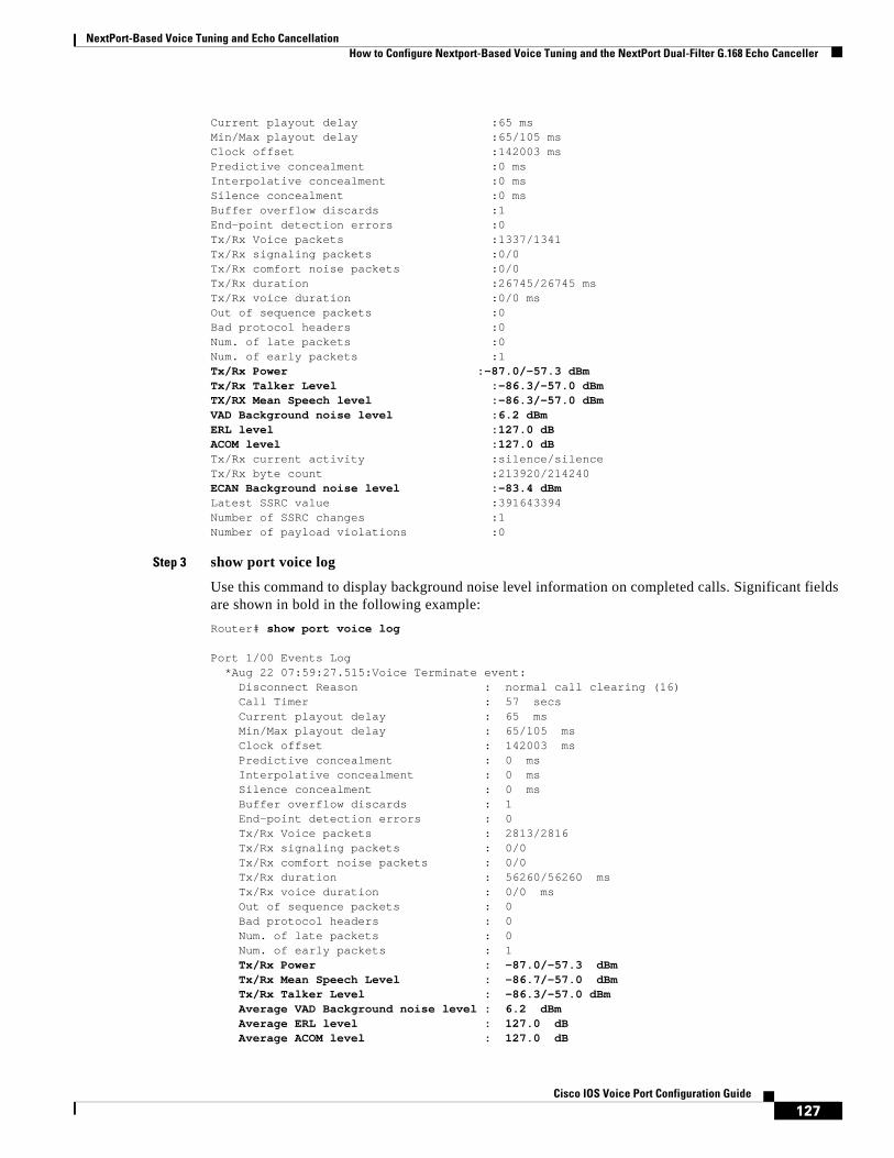
NextPort-Based Voice Tuning and Echo Cancellation How to Configure Nextport-Based Voice Tuning and the NextPort Dual-Filter G.168 Echo Canceller
127Cisco IOS Voice Port Configuration Guide
Current playout delay :65 msMin/Max playout delay :65/105 msClock offset :142003 msPredictive concealment :0 msInterpolative concealment :0 msSilence concealment :0 msBuffer overflow discards :1End-point detection errors :0Tx/Rx Voice packets :1337/1341Tx/Rx signaling packets :0/0Tx/Rx comfort noise packets :0/0Tx/Rx duration :26745/26745 msTx/Rx voice duration :0/0 msOut of sequence packets :0Bad protocol headers :0Num. of late packets :0Num. of early packets :1Tx/Rx Power :-87.0/-57.3 dBmTx/Rx Talker Level :-86.3/-57.0 dBmTX/RX Mean Speech level :-86.3/-57.0 dBmVAD Background noise level :6.2 dBmERL level :127.0 dBACOM level :127.0 dBTx/Rx current activity :silence/silenceTx/Rx byte count :213920/214240ECAN Background noise level :-83.4 dBmLatest SSRC value :391643394Number of SSRC changes :1Number of payload violations :0
Step 3 show port voice log
Use this command to display background noise level information on completed calls. Significant fields are shown in bold in the following example:
Router# show port voice log
Port 1/00 Events Log *Aug 22 07:59:27.515:Voice Terminate event: Disconnect Reason : normal call clearing (16) Call Timer : 57 secs Current playout delay : 65 ms Min/Max playout delay : 65/105 ms Clock offset : 142003 ms Predictive concealment : 0 ms Interpolative concealment : 0 ms Silence concealment : 0 ms Buffer overflow discards : 1 End-point detection errors : 0 Tx/Rx Voice packets : 2813/2816 Tx/Rx signaling packets : 0/0 Tx/Rx comfort noise packets : 0/0 Tx/Rx duration : 56260/56260 ms Tx/Rx voice duration : 0/0 ms Out of sequence packets : 0 Bad protocol headers : 0 Num. of late packets : 0 Num. of early packets : 1 Tx/Rx Power : -87.0/-57.3 dBm Tx/Rx Mean Speech Level : -86.7/-57.0 dBm
Tx/Rx Talker Level : -86.3/-57.0 dBm Average VAD Background noise level : 6.2 dBm Average ERL level : 127.0 dB Average ACOM level : 127.0 dB
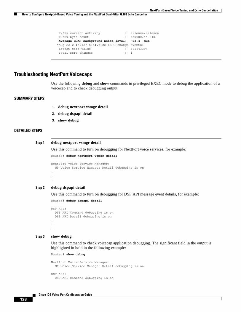
NextPort-Based Voice Tuning and Echo Cancellation How to Configure Nextport-Based Voice Tuning and the NextPort Dual-Filter G.168 Echo Canceller
128Cisco IOS Voice Port Configuration Guide
Tx/Rx current activity : silence/silence Tx/Rx byte count : 450080/450240 Average ECAN Background noise level: -83.4 dBm *Aug 22 07:59:27.515:Voice SSRC change events: Latest ssrc value : 391643394 Total ssrc changes : 1
Troubleshooting NextPort Voicecaps
Use the following debug and show commands in privileged EXEC mode to debug the application of a voicecap and to check debugging output:
SUMMARY STEPS
1. debug nextport vsmgr detail
2. debug dspapi detail
3. show debug
DETAILED STEPS
Step 1 debug nextport vsmgr detail
Use this command to turn on debugging for NextPort voice services, for example:
Router# debug nextport vsmgr detail
NextPort Voice Service Manager: NP Voice Service Manager Detail debugging is on...
Step 2 debug dspapi detail
Use this command to turn on debugging for DSP API message event details, for example:
Router# debug dspapi detail
DSP API: DSP API Command debugging is on DSP API Detail debugging is on...
Step 3 show debug
Use this command to check voicecap application debugging. The significant field in the output is highlighted in bold in the following example:
Router# show debug
NextPort Voice Service Manager: NP Voice Service Manager Detail debugging is on
DSP API: DSP API Command debugging is on

NextPort-Based Voice Tuning and Echo Cancellation How to Configure Nextport-Based Voice Tuning and the NextPort Dual-Filter G.168 Echo Canceller
129Cisco IOS Voice Port Configuration Guide
DSP API Detail debugging is on*Aug 22 08:34:47.399:dspapi [2/1:1 (4)] dsp_init*Aug 22 08:34:47.399:dspapi [2/1:1 (4)] dsp_voice_config_params:10 params*Aug 22 08:34:47.399: [0] ENCAP RTP:t_ssrc=20 r_ssrc=0 t_vpxcc=0 r_vpxcc=0 ifp_payload_type=122 sid_support=19 tse_payload=101 seq_num_start=6303 redundancy=0 cc_payload_typRouter# e=125 fax_payload_type=122 alaw_pcm_switchover=8 mulaw_pcm_switchover=0 dtmf_payload_type=121, nte_rcv_payload_type=101dynamic_payload=0, codec=5*Aug 22 08:34:47.399: [1] PO_JITTER:mode=2 initial=60 max=200 min=40 fax_nom=300*Aug 22 08:34:47.399: [2] INBAND_SIG:mode=0x1 enable*Aug 22 08:34:47.399: [3] ECHO_CANCEL:flags=0x17 echo_len=256*Aug 22 08:34:47.399: [4] IDLE_CODE_DET:enable = 0 code=0x0 duration=6000*Aug 22 08:34:47.403: [5] GAIN:input=0 output=0*Aug 22 08:34:47.403: [6] CNG:Router# 1*Aug 22 08:34:47.403: [7] INFO_FIELD_SIZE:160*Aug 22 08:34:47.403: [8] DIGIT_RELAY:2*Aug 22 08:34:47.403: [9] VOICECAP:EXAMPLE*Aug 22 08:34:47.403:dspapi [2/1:1 (4)] dsp_start_service:G711_U (5)*Aug 22 08:34:47.403:Matched voicecap:v0=0 v1=1*Aug 22 08:34:47.403:msg length = 0x001D*Aug 22 08:34:47.403:session ID = 0x006D*Aug 22 08:34:47.403: msg tag = 0x0000*Aug 22 08:34:47.403: msg ID = 0xF201
Configuring the NextPort Dual-Filter G.168 Echo CancellerThe NextPort dual-filter G.168 echo canceller is enabled by default on NextPort platforms in Cisco IOS Release 12.3(11)T and later releases. However, you can adjust the echo canceller tail coverage time at the voice-port interface by completing the following tasks:
SUMMARY STEPS
1. enable
2. configure terminal
3. voice-port slot/port:D
4. echo-cancel coverage {24 | 32 | 48 | 64 | 80 | 96 | 112 | 128}
5. exit
DETAILED STEPS
Command or Action Purpose
Step 1 enable
Example:Router> enable
Enables privileged EXEC mode.
• Enter your password if prompted.
Step 2 configure terminal
Example:Router# configure terminal
Enters global configuration mode.

NextPort-Based Voice Tuning and Echo Cancellation How to Configure Nextport-Based Voice Tuning and the NextPort Dual-Filter G.168 Echo Canceller
130Cisco IOS Voice Port Configuration Guide
Configuration Examples for Nextport-Based Voice Tuning and the NextPort Dual-Filter G.168 Echo Canceller
The following sections contain examples that could be used to optimize a NextPort-based gateway for a given telephone network:
• High ERL in the Network: Example, page 130
• Low ERL in the Network: Example, page 131
• Clipped or Squelched Speech and Low ERL in the Network: Example, page 131
• Dynamic Attenuation: Example, page 131
• Echo Canceller Tail Coverage: Example, page 132
High ERL in the Network: Example
Register v270 is used to set the limit for the minimum expected ERLs that the gateway will encounter. If the gateway encounters ERLs that are lower than the v270 setting, the echo canceller performance will be suboptimal.
The default setting for v270 is 6 dB. This setting should work well for usual telephone networks. However, when the gateway is used on a well-managed telephone network with organized loss plans in place, the ERL is often greater than 6 dB. In these cases, v270 can be raised. Making this change reduces any clipping of the near-end signal; however, it will underperform if a low ERL is encountered.
In this example, the network is designed to have an ERL of 12 dB or greater. In this case, the following voicecap may improve performance. Notice that the value for v270 is entered as decibels multiplied by 10.
Router> enableRouter# configure terminal Router(config)# voicecap entry qualityERL v270=120Router(config)# end
Step 3 voice-port slot/port:D
Example:Router(config)# voice-port 3/0:D
Enters voice-port configuration mode on the selected slot and port.
Step 4 echo-cancel coverage {24 | 32 | 48 | 64 | 80 | 96 | 112 | 128}
Example:Router(config-voiceport)# echo-cancel coverage 64
Adjusts the size of the echo canceller (EC) and selects the extended EC when the Cisco default EC is present.
• Starting with Cisco IOS Release 12.4(20)T, the default coverage time and maximum possible coverage is 128 ms for both 8.x and 10.2.2 SPEware versions.
Step 5 exit
Example:Router(config-voiceport)# exit
Exits voice-port configuration mode and completes the configuration.
Command or Action Purpose

NextPort-Based Voice Tuning and Echo Cancellation How to Configure Nextport-Based Voice Tuning and the NextPort Dual-Filter G.168 Echo Canceller
131Cisco IOS Voice Port Configuration Guide
Low ERL in the Network: Example
Unlike the scenario described in the previous example, some telephone networks may not always produce sufficient ERLs to meet the default setting of 6 dB. The best way to solve this problem would be to institute better loss plans on the telephone network. However, because this is not always possible, a voicecap can be used to alleviate the problem.
A low ERL means that the echo canceller must do a much deeper cancellation to remove sufficient echo. Also, lowering the minimum ERL can increase the incidence of clipping. The best way to improve this situation is to make up for the telephone network’s lack of loss plan by adding some loss in the gateway. If the lowest ERL seen is 4 dB, adding 1 dB of output attenuation and –1 dB of input gain will ensure that the echo canceller never sees more than a 6-dB effective ERL.
Adding this attenuation can be done by entering a voicecap, but using the CLI is the recommended approach in this example. The following commands set the gains that are needed for this example:
Router> enableRouter# configure terminal Router(config)# voice-port 3/0:DRouter(config-voiceport)# output attenuation 1Router(config-voiceport)# input gain -1 Router(config-voiceport)# end
Clipped or Squelched Speech and Low ERL in the Network: Example
In this example, a network in which signal level imbalance is already causing clipping to occur with a MinERL setting of 6 dB and in which ERLs of less than 6 dB are already occurring, a dual approach must be taken. To stop the clipping, the MinERL setting should be lowered to 12 dB. If 4-dB ERLs are occurring, 4 dB of attenuation must be added to the input and the output to ensure that there is 12 dB of effective ERL at the echo canceller (4 dB of real ERL, plus 4 dB of output attenuation, plus 4 dB of input attenuation equals 12 dB of effective ERL). To create these settings, the following commands are used:
Router> enableRouter# configure terminal Router(config)# voicecap entry qualityERL v270=120Router(config)# voice-port 3/0:DRouter(config-voiceport)# voicecap configure qualityERLRouter(config-voiceport)# output attenuation 4Router(config-voiceport)# input gain -4Router(config-voiceport)# end
Dynamic Attenuation: Example
It is possible that worst-case settings are only required when the primary telephone circuits are all used and an alternate carrier with a poor loss plan must be used instead. For these cases, the dynamic attenuation feature removes the attenuation when the ERL is sufficient. In the following example, 4 dB of input and output attenuation is to be removed when it is not necessary to ensure the minimum ERL setting. To do this, the dynamic attenuation feature (using v289) is enabled. The required ERL must be set before attenuation is removed (using v290), and minimum attenuation levels for the input and output (using v291 and v292) must also be set. In this example, attenuation is set to 15 dB and then removed.
Router> enableRouter# configure terminal Router(config)# voicecap entry dynatten v270=120 v289=1 v290=15 v291=0 v292=0Router(config)# voice-port 3/0:DRouter(config-voiceport)# voicecap configure dynattenRouter(config-voiceport)# output attenuation 4Router(config-voiceport)# input gain -4

NextPort-Based Voice Tuning and Echo Cancellation How to Configure Nextport-Based Voice Tuning and the NextPort Dual-Filter G.168 Echo Canceller
132Cisco IOS Voice Port Configuration Guide
Router(config-voiceport)# end
Echo Canceller Tail Coverage: Example
The following example adjusts echo canceller tail coverage to 64 ms on the Cisco AS5400:
Router(config) voice-port 1/0:0Router(config-voiceport)# echo-cancel coverage 64
Enabling NextPort Echo Canceller Control for G.711 Encoded VoIP PacketsThis section describes how to enable NextPort echo canceller control on the Cisco AS5350, AS5400, AS5400HPX, and AS5850 universal gateways when these gateways detect 2100 Hz tones, received in G.711 encoded VoIP packets. You can enable NextPort voicecaps to control the echo canceller from either the PSTN or IP side of the network.
Note NextPort control over the echo canceller is possible only in G.711 codec modes. Cisco recommends that you do not enable NextPort control over the echo canceller in conjunction with modem pass-through.
IP tone detection and NextPort control over the echo canceller is enabled using the command-line interface. Use the following commands to enable NextPort control over the echo canceller by creating a voicecap entry and applying it to the voice port.
SUMMARY STEPS
1. enable
2. configure terminal
3. voicecap entry name string
4. voice-port slot/port
5. voicecap configure name
6. exit
DETAILED STEPS
Command or Action Purpose
Step 1 enable
Example:Router> enable
Enables privileged EXEC mode.
• Enter your password if prompted.
Step 2 configure terminal
Example:Router# configure terminal
Enters global configuration mode.
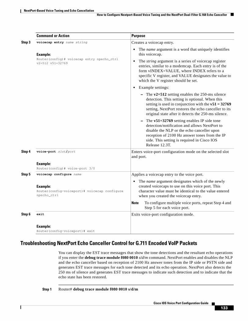
NextPort-Based Voice Tuning and Echo Cancellation How to Configure Nextport-Based Voice Tuning and the NextPort Dual-Filter G.168 Echo Canceller
133Cisco IOS Voice Port Configuration Guide
Troubleshooting NextPort Echo Canceller Control for G.711 Encoded VoIP Packets
You can display the EST trace messages that show the tone detections and the resultant echo operations if you enter the debug trace module f080 0010 s/d/m command. NextPort enables and disables the NLP and the echo canceller based on reception of 2100 Hz answer tones from the IP side or PSTN side and generates EST trace messages for each tone detected and its echo operation. NextPort also detects the 250 ms of silence and generates EST trace messages to indicate such detection and to indicate that the echo state has been restored.
Step 1 Router# debug trace module f080 0010 s/d/m
Step 3 voicecap entry name string
Example:Router(config)# voicecap entry npecho_ctrl v2=512 v51=32769
Creates a voicecap entry.
• The name argument is a word that uniquely identifies this voicecap.
• The string argument is a series of voicecap register entries, similar to a modemcap. Each entry is of the form vINDEX=VALUE, where INDEX refers to a specific V register, and VALUE designates the value to which the V register should be set.
• Example settings:
– The v2=512 setting enables the 250-ms silence detection. This setting is optional. When this setting is used in conjunction with the v51 = 32769 setting, NextPort restores the echo canceller to its original state after it detects the 250-ms silence.
– The v51=32769 setting enables IP side tone detection/notification and allows NextPort to disable the NLP or the echo canceller upon reception of 2100 Hz answer tones from the IP side. This setting is required in Cisco IOS Release 12.3T.
Step 4 voice-port slot/port
Example:Router(config)# voice-port 3/0
Enters voice-port configuration mode on the selected slot and port.
Step 5 voicecap configure name
Example:Router(config-voiceport)# voicecap configure npecho_ctrl
Applies a voicecap entry to the voice port.
• The name argument designates which of the newly created voicecaps to use on this voice port. This character value must be identical to the value entered when you created the voicecap entry.
Note To configure multiple voice ports, repeat Step 4 and Step 5 for each voice port.
Step 6 exit
Example:Router(config-voiceport)# exit
Exits voice-port configuration mode.
Command or Action Purpose

NextPort-Based Voice Tuning and Echo Cancellation How to Configure Nextport-Based Voice Tuning and the NextPort Dual-Filter G.168 Echo Canceller
134Cisco IOS Voice Port Configuration Guide
Use this command to display the EST trace messages. In the command, s/d/m is defined as follows:
• s = slot
• d = dfc
• m = module number
When the default configuration values for Index 51 and Index 52 are used, IP tone detection and notification are disabled, and all existing features continue to function normally.
The following example shows EST trace messages collected from the console:
Router#*Apr 26 21:40:51.735: 00:00:14: Port Trace Event:*Apr 26 21:40:51.735: Port : 3/00*Apr 26 21:40:51.735: Address : 0x3000000*Apr 26 21:40:51.735: Trace Event: 0x2*Apr 26 21:40:51.735: Data Format: ASCII*Apr 26 21:40:51.735: Data Len : 56*Apr 26 21:40:51.735: Data : Session 0x0144 Received Early ANS tone 0x01 from IP side*Apr 26 21:40:51.735: 00:00:14: Port Trace Event:*Apr 26 21:40:51.735: Port : 3/00*Apr 26 21:40:51.735:Router# Address : 0x3000000*Apr 26 21:40:51.735: Trace Event: 0x2*Apr 26 21:40:51.735: Data Format: ASCII*Apr 26 21:40:51.735: Data Len : 63*Apr 26 21:40:51.735: Data : Session 0x0144 Received Tone Off ntf for code 0x01 from IP side*Apr 26 21:40:51.735: 00:00:14: Port Trace Event:*Apr 26 21:40:51.735: Port : 3/00*Apr 26 21:40:51.735: Address : 0x3000000*Apr 26 21:40:51.735: Trace Event: 0x2*Apr 26 21:40:51.735: Data Format: ASCIIRouter#*Apr 26 21:40:51.735: Data Len : 45*Apr 26 21:40:51.735: Data : Session 0x0144 Received ANS tone 0x03 from IP*Apr 26 21:40:51.735: 00:00:14: Port Trace Event:*Apr 26 21:40:51.735: Port : 3/00*Apr 26 21:40:51.735: Address : 0x3000000*Apr 26 21:40:51.735: Trace Event: 0x2*Apr 26 21:40:51.735: Data Format: ASCII*Apr 26 21:40:51.735: Data Len : 47*Apr 26 21:40:51.735: Data : Session 0x0144 Non-linear Processor Is Disabled*AprRouter# 26 21:40:51.735: 00:00:14: Port Trace Event:*Apr 26 21:40:51.735: Port : 3/00*Apr 26 21:40:51.735: Address : 0x3000000*Apr 26 21:40:51.735: Trace Event: 0x2*Apr 26 21:40:51.735: Data Format: ASCII*Apr 26 21:40:51.735: Data Len : 63*Apr 26 21:40:51.735: Data : Session 0x0144 Received Tone Off ntf for code 0x03 from IP side*Apr 26 21:40:51.735: 00:00:14: Port Trace Event:*Apr 26 21:40:51.735: Port : 3/00*Apr 26 21:40:51.735:Router# Address : 0x3000000*Apr 26 21:40:51.735: Trace Event: 0x2*Apr 26 21:40:51.735: Data Format: ASCII*Apr 26 21:40:51.735: Data Len : 47*Apr 26 21:40:51.735: Data : Session 0x0144 Received ANSam tone 0x07 from IP*Apr 26 21:40:51.735: 00:00:13: Port Trace Event:*Apr 26 21:40:51.735: Port : 3/00*Apr 26 21:40:51.735: Address : 0x3000000

NextPort-Based Voice Tuning and Echo Cancellation How to Configure Nextport-Based Voice Tuning and the NextPort Dual-Filter G.168 Echo Canceller
135Cisco IOS Voice Port Configuration Guide
*Apr 26 21:40:51.735: Trace Event: 0x2*Apr 26 21:40:51.735: Data Format: ASCII*Apr 26 21:40:5Router#1.735: Data Len : 63*Apr 26 21:40:51.735: Data : Session 0x0144 Received Tone Off ntf for code 0x07 from IP side*Apr 26 21:40:51.739: 00:00:13: Port Trace Event:*Apr 26 21:40:51.739: Port : 3/00*Apr 26 21:40:51.739: Address : 0x3000000*Apr 26 21:40:51.739: Trace Event: 0x2*Apr 26 21:40:51.739: Data Format: ASCII*Apr 26 21:40:51.739: Data Len : 48*Apr 26 21:40:51.739: Data : Session 0x0144 Received /ANSam tone 0x0f from IPRouter#*Apr 26 21:40:51.739: 00:00:13: Port Trace Event:*Apr 26 21:40:51.739: Port : 3/00*Apr 26 21:40:51.739: Address : 0x3000000*Apr 26 21:40:51.739: Trace Event: 0x2*Apr 26 21:40:51.739: Data Format: ASCII*Apr 26 21:40:51.739: Data Len : 31*Apr 26 21:40:51.739: Data : Session 0x0144 ECAN Is Disabled*Apr 26 21:40:51.739: 00:00:04: Port Trace Event:*Apr 26 21:40:51.739: Port : 3/00*Apr 26 21:40:51.739: Address : 0x3000000Router#*Apr 26 21:40:51.739: Trace Event: 0x2*Apr 26 21:40:51.739: Data Format: ASCII*Apr 26 21:40:51.739: Data Len : 63*Apr 26 21:40:51.739: Data : Session 0x0144 Received Tone Off ntf for code 0x0f from IP side
*Apr 26 21:46:36.431: 00:00:08: Port Trace Event:*Apr 26 21:46:36.431: Port : 3/00*Apr 26 21:46:36.431: Address : 0x3000000 *Apr 26 21:46:36.431: Trace Event: 0x2*Apr 26 21:46:36.431: Data Format: ASCII*Apr 26 21:46:36.431: Data Len : 43*Apr 26 21:46:36.431: Data : Session 0x0144 detected 250 msec of silence*Apr 26 21:46:36.431: 00:00:08: Port Trace Event:*Apr 26 21:46:36.431: Port : 3/00*Apr 26 21:46:36.431: Address : 0x3000000 *Apr 26 21:46:36.435: Trace Event: 0x2*Apr 26 21:46:36.435: Data Format: ASCII*Apr 26 21:46:36.435: Data Len : 41*Apr 26 21:46:36.435: Data : Session 0x0144 Ecan State 0x0007 Restored
CCDE, CCENT, Cisco Eos, Cisco Lumin, Cisco Nexus, Cisco StadiumVision, Cisco TelePresence, the Cisco logo, DCE, and Welcome to the Human Network are trademarks; Changing the Way We Work, Live, Play, and Learn and Cisco Store are service marks; and Access Registrar, Aironet, AsyncOS, Bringing the Meeting To You, Catalyst, CCDA, CCDP, CCIE, CCIP, CCNA, CCNP, CCSP, CCVP, Cisco, the Cisco Certified Internetwork Expert logo, Cisco IOS, Cisco Press, Cisco Systems, Cisco Systems Capital, the Cisco Systems logo, Cisco Unity, Collaboration Without Limitation, EtherFast, EtherSwitch, Event Center, Fast Step, Follow Me Browsing, FormShare, GigaDrive, HomeLink, Internet Quotient, IOS, iPhone, iQ Expertise, the iQ logo, iQ Net Readiness Scorecard, iQuick Study, IronPort, the IronPort logo, LightStream, Linksys, MediaTone, MeetingPlace, MeetingPlace Chime Sound, MGX, Networkers, Networking Academy, Network Registrar, PCNow, PIX, PowerPanels, ProConnect, ScriptShare, SenderBase, SMARTnet, Spectrum Expert, StackWise, The Fastest Way to Increase Your Internet Quotient, TransPath, WebEx, and the WebEx logo are registered trademarks of Cisco Systems, Inc. and/or its affiliates in the United States and certain other countries.
All other trademarks mentioned in this document or Website are the property of their respective owners. The use of the word partner does not imply a partnership relationship between Cisco and any other company. (0807R)
Any Internet Protocol (IP) addresses used in this document are not intended to be actual addresses. Any examples, command display output, and figures included in the document are shown for illustrative purposes only. Any use of actual IP addresses in illustrative content is unintentional and coincidental.
© 2008 Cisco Systems, Inc. All rights reserved.

NextPort-Based Voice Tuning and Echo Cancellation How to Configure Nextport-Based Voice Tuning and the NextPort Dual-Filter G.168 Echo Canceller
136Cisco IOS Voice Port Configuration Guide

Americas Headquarters:Cisco Systems, Inc., 170 West Tasman Drive, San Jose, CA 95134-1706 USA
© 2008 Cisco Systems, Inc. All rights reserved.
Verifying Analog and Digital Voice-Port Configurations
This chapter describes some basic procedures and specific CLI commands you can use to verify the set up and configuration of the analog and digital voice ports on the routers in your voice network.
Information About Verifying Analog and Digital Voice-Port Configurations
After configuring the voice ports on your router, there are two simple verifications you can use to check the operation of the telephony handset. There are also eight CLI commands you can use to verify proper operation of the configuration.
How to Verify Analog and Digital Voice-Port ConfigurationsTo verify the operability of the analog and digital voice-port configurations on your voice network, complete the following tasks.
SUMMARY STEPS
1. Check for a dial tone.
2. Check for DTMF detection.
3. show voice port summary
4. show voice port
5. show running-config
6. show controller
7. show voice dsp
8. show voice call summary
9. show call active voice

Verifying Analog and Digital Voice-Port Configurations How to Verify Analog and Digital Voice-Port Configurations
138Cisco IOS Voice Port Configuration Guide
10. show call history voice
DETAILED STEPS
Step 1 Check for a dial tone.
Pick up the handset of an attached telephony device and check for a dial tone.
Step 2 Check for Dual-Tone Multifrequency (DTMF) detection.
If you have dial tone, check for DTMF detection. If the dial tone stops when you dial a digit, then the voice port is probably configured properly.
Step 3 show voice port summary
Use this command to identify the port numbers of voice interfaces installed in your router. For examples of the output, see the “Examples” section on page 139.
Step 4 show voice port
Use this command to verify voice-port parameter settings. Refer to Table 2 for the appropriate syntax for your platform. For sample output, see the “show voice port Command: Examples” section on page 140.
Step 5 show running-config
Use this command to verify the codec complexity setting for digital T1/E1 connections. If medium complexity is specified for the voice card, the codec complexity command is not displayed. If high complexity is specified, the codec complexity high command is displayed. The following example shows output when high complexity is specified:
Router# show running-config...hostname router-alpha
Table 2 Show Voice Port Command Syntax
Platform Voice Port Type Command Syntax
Cisco 1750 Analog show voice port [slot/port | summary]
Cisco 2600 series Cisco 3600 series Cisco 3700 series
Analog show voice port [slot/port | summary]
Digital show voice port [slot/port:ds0-group-number | summary]
Cisco MC3810 Analog show voice port [slot/port | summary]
Digital show voice port [slot:ds0-group-number | summary]
Cisco AS5300 Digital show voice port [controller:{ds0-group-number | D}] [summary]
Cisco AS5350Cisco AS5400Cisco AS5850
Digital show voice port [slot/controller:{ds0-group-number | D}] [summary]
Cisco AS5800 Digital show voice port {shelf/slot/port:ds0-group-number}
Cisco 7200 series Digital show voice port {slot/port-adapter:ds0-group-number}
Cisco 7500 series Digital show voice port {slot/port-adapter/slot:ds0-group-number}
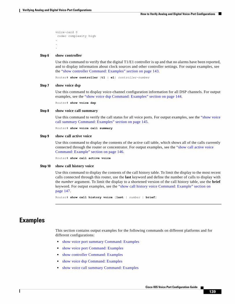
Verifying Analog and Digital Voice-Port Configurations How to Verify Analog and Digital Voice-Port Configurations
139Cisco IOS Voice Port Configuration Guide
voice-card 0 codec complexity high ...
Step 6 show controller
Use this command to verify that the digital T1/E1 controller is up and that no alarms have been reported, and to display information about clock sources and other controller settings. For output examples, see the “show controller Command: Examples” section on page 143.
Router# show controller {t1 | e1} controller-number
Step 7 show voice dsp
Use this command to display voice-channel configuration information for all DSP channels. For output examples, see the “show voice dsp Command: Examples” section on page 144.
Router# show voice dsp
Step 8 show voice call summary
Use this command to verify the call status for all voice ports. For output examples, see the “show voice call summary Command: Examples” section on page 145.
Router# show voice call summary
Step 9 show call active voice
Use this command to display the contents of the active call table, which shows all of the calls currently connected through the router or concentrator. For output examples, see the “show call active voice Command: Example” section on page 146.
Router# show call active voice
Step 10 show call history voice
Use this command to display the contents of the call history table. To limit the display to the most recent calls connected through this router, use the last keyword and define the number of calls to display with the number argument. To limit the display to a shortened version of the call history table, use the brief keyword. For output examples, see the “show call history voice Command: Example” section on page 147.
Router# show call history voice [last | number | brief]
ExamplesThis section contains output examples for the following commands on different platforms and for different configurations:
• show voice port summary Command: Examples
• show voice port Command: Examples
• show controller Command: Examples
• show voice dsp Command: Examples
• show voice call summary Command: Examples

Verifying Analog and Digital Voice-Port Configurations How to Verify Analog and Digital Voice-Port Configurations
140Cisco IOS Voice Port Configuration Guide
• show call active voice Command: Example
• show call history voice Command: Example
show voice port summary Command: Examples
Cisco 3640 Router Analog Voice Port
The following output is from a Cisco 3640 router:
Router# show voice port summary IN OUTPORT CH SIG-TYPE ADMIN OPER STATUS STATUS EC====== == ========== ===== ==== ======== ======== ==2/0/0 -- e&m-wnk up dorm idle idle y 2/0/1 -- e&m-wnk up dorm idle idle y 2/1/0 -- fxs-ls up dorm on-hook idle y 2/1/1 -- fxs-ls up dorm on-hook idle y
Cisco MC3810 Digital Voice Port
The following output is from a Cisco MC3810:
Router# show voice port summary IN OUTPORT CH SIG-TYPE ADMIN OPER STATUS STATUS EC====== == ========== ===== ==== ======== ======== ==0:17 18 fxo-ls down down idle on-hook y0:18 19 fxo-ls up dorm idle on-hook y0:19 20 fxo-ls up dorm idle on-hook y0:20 21 fxo-ls up dorm idle on-hook y0:21 22 fxo-ls up dorm idle on-hook y0:22 23 fxo-ls up dorm idle on-hook y0:23 24 e&m-imd up dorm idle idle y1/1 -- fxs-ls up dorm on-hook idle y1/2 -- fxs-ls up dorm on-hook idle y1/3 -- e&m-imd up dorm idle idle y1/4 -- e&m-imd up dorm idle idle y1/5 -- fxo-ls up dorm idle on-hook y1/6 -- fxo-ls up dorm idle on-hook y
show voice port Command: Examples
Cisco 3600 Series Router Analog E&M Voice Port
The following output is from a Cisco 3600 series router analog E&M voice port:
Router# show voice port 1/0
E&M Slot is 1, Sub-unit is 0, Port is 0 Type of VoicePort is E&M Operation State is unknown Administrative State is unknown The Interface Down Failure Cause is 0 Alias is NULL Noise Regeneration is disabled Non Linear Processing is disabled Music On Hold Threshold is Set to 0 dBm In Gain is Set to 0 dB Out Attenuation is Set to 0 dB Echo Cancellation is disabled Echo Cancel Coverage is set to 16ms Connection Mode is Normal

Verifying Analog and Digital Voice-Port Configurations How to Verify Analog and Digital Voice-Port Configurations
141Cisco IOS Voice Port Configuration Guide
Connection Number is Initial Time Out is set to 0 s Interdigit Time Out is set to 0 s Analog Info Follows: Region Tone is set for northamerica Currently processing none Maintenance Mode Set to None (not in mtc mode) Number of signaling protocol errors are 0 Voice card specific Info Follows: Signal Type is wink-start Operation Type is 2-wire Impedance is set to 600r Ohm E&M Type is unknown Dial Type is dtmf In Seizure is inactive Out Seizure is inactive Digit Duration Timing is set to 0 ms InterDigit Duration Timing is set to 0 ms Pulse Rate Timing is set to 0 pulses/second InterDigit Pulse Duration Timing is set to 0 ms Clear Wait Duration Timing is set to 0 ms Wink Wait Duration Timing is set to 0 ms Wink Duration Timing is set to 0 ms Delay Start Timing is set to 0 ms Delay Duration Timing is set to 0 ms
Cisco 3600 Series Router Analog FXS Voice Port
The following output is from a Cisco 3600 series router analog Foreign Exchange Service (FXS) voice port:
Router# show voice port 1/2
Voice port 1/2 Slot is 1, Port is 2 Type of VoicePort is FXS Operation State is UP Administrative State is UP No Interface Down Failure Description is not set Noise Regeneration is enabled Non Linear Processing is enabled In Gain is Set to 0 dB Out Attenuation is Set to 0 dB Echo Cancellation is enabled Echo Cancel Coverage is set to 8 ms Connection Mode is normal Connection Number is not set Initial Time Out is set to 10 s Interdigit Time Out is set to 10 s Coder Type is g729ar8 Companding Type is u-law Voice Activity Detection is disabled Ringing Time Out is 180 s Wait Release Time Out is 30 s Nominal Playout Delay is 80 milliseconds Maximum Playout Delay is 160 milliseconds
Analog Info Follows: Region Tone is set for northamerica Currently processing Voice Maintenance Mode Set to None (not in mtc mode) Number of signaling protocol errors are 0 Impedance is set to 600r Ohm

Verifying Analog and Digital Voice-Port Configurations How to Verify Analog and Digital Voice-Port Configurations
142Cisco IOS Voice Port Configuration Guide
Analog interface A-D gain offset = -3 dB Analog interface D-A gain offset = -3 dB Voice card specific Info Follows: Signal Type is loopStart Ring Frequency is 20 Hz Hook Status is On Hook Ring Active Status is inactive Ring Ground Status is inactive Tip Ground Status is active Digit Duration Timing is set to 100 ms InterDigit Duration Timing is set to 100 ms Ring Cadence are [20 40] * 100 msec InterDigit Pulse Duration Timing is set to 500 ms
Cisco 3600 Series Router Digital E&M Voice Port
The following output is from a Cisco 3600 series router digital E&M voice port:
Router# show voice port 1/0:1 receEive and transMit Slot is 1, Sub-unit is 0, Port is 1 Type of VoicePort is E&M Operation State is DORMANT Administrative State is UP No Interface Down Failure Description is not set Noise Regeneration is enabled Non Linear Processing is enabled Music On Hold Threshold is Set to -38 dBm In Gain is Set to 0 dB Out Attenuation is Set to 0 dB Echo Cancellation is enabled Echo Cancel Coverage is set to 8 ms Connection Mode is normal Connection Number is not set Initial Time Out is set to 10 s Interdigit Time Out is set to 10 s Region Tone is set for US
Cisco AS5300 T1 CAS Voice Port
The following output is from a Cisco AS5300 T1 channel-associated signaling (CAS) voice port:
Router# show voice port DS0 Group 1:0 - 1:0 Type of VoicePort is CAS Operation State is DORMANT Administrative State is UP No Interface Down Failure Description is not set Noise Regeneration is enabled Non Linear Processing is enabled Music On Hold Threshold is Set to -38 dBm In Gain is Set to 0 dB Out Attenuation is Set to 0 dB Echo Cancellation is enabled Echo Cancel Coverage is set to 8 ms Playout-delay Mode is set to default Playout-delay Nominal is set to 60 ms Playout-delay Maximum is set to 200 ms Connection Mode is normal Connection Number is not set Initial Time Out is set to 10 s Interdigit Time Out is set to 10 s

Verifying Analog and Digital Voice-Port Configurations How to Verify Analog and Digital Voice-Port Configurations
143Cisco IOS Voice Port Configuration Guide
Call-Disconnect Time Out is set to 60 s Ringing Time Out is set to 180 s Companding Type is u-law Region Tone is set for US Wait Release Time Out is 30 s Station name None, Station number None Voice card specific Info Follows: DS0 channel specific status info: IN OUT PORT CH SIG-TYPE OPER STATUS STATUS TIP RING
Cisco 7200 Series Router Digital E&M Voice Port
The following output is from a Cisco 7200 series router digital E&M voice port:
Router# show voice port 1/0:1
receEive and transMit Slot is 1, Sub-unit is 0, Port is 1 << voice-port 1/0:1
Type of VoicePort is E&M
Operation State is DORMANT
Administrative State is UP
No Interface Down Failure Description is not set Noise Regeneration is enabled Non Linear Processing is enabled Music On Hold Threshold is Set to -38 dBm In Gain is Set to 0 dB
Out Attenuation is Set to 0 dB
Echo Cancellation is enabled
Echo Cancel Coverage is set to 8 ms Connection Mode is normal Connection Number is not set Initial Time Out is set to 10 s
Interdigit Time Out is set to 10 s
Region Tone is set for US
show controller Command: Examples
Cisco 3600 Series Router T1 Controller
The following output is from a Cisco 3600 series router with a T1 controller:
Router# show controller T1 1/1/0
T1 1/0/0 is up. Applique type is Channelized T1 Cablelength is long gain36 0db No alarms detected. alarm-trigger is not set Framing is ESF, Line Code is B8ZS, Clock Source is Line. Data in current interval (180 seconds elapsed): 0 Line Code Violations, 0 Path Code Violations

Verifying Analog and Digital Voice-Port Configurations How to Verify Analog and Digital Voice-Port Configurations
144Cisco IOS Voice Port Configuration Guide
0 Slip Secs, 0 Fr Loss Secs, 0 Line Err Secs, 0 Degraded Mins 0 Errored Secs, 0 Bursty Err Secs, 0 Severely Err Secs, 0 Unavail Secs
Cisco MC3810 E1 Controller
The following output is from a Cisco MC3810 with an E1 controller:
Router# show controller e1 1/0
E1 1/0 is up. Applique type is Channelized E1 Cablelength is short 133 Description: E1 WIC card Alpha No alarms detected. Framing is CRC4, Line Code is HDB3, Clock Source is Line Primary. Data in current interval (1 seconds elapsed): 0 Line Code Violations, 0 Path Code Violations 0 Slip Secs, 0 Fr Loss Secs, 0 Line Err Secs, 0 Degraded Mins 0 Errored Secs, 0 Bursty Err Secs, 0 Severely Err Secs, 0 Unavail Secs
Cisco AS5800 T1 Controller
The following output is from a Cisco AS5800 with a T1 controller:
Router# show controller t1 2
T1 2 is up. No alarms detected. Version info of slot 0: HW: 2, Firmware: 16, PLD Rev: 0 Manufacture Cookie Info: EEPROM Type 0x0001, EEPROM Version 0x01, Board ID 0x42, Board Hardware Version 1.0, Item Number 73-2217-4, Board Revision A0, Serial Number 06467665, PLD/ISP Version 0.0, Manufacture Date 14-Nov-1997. Framing is ESF, Line Code is B8ZS, Clock Source is Internal. Data in current interval (269 seconds elapsed): 0 Line Code Violations, 0 Path Code Violations 0 Slip Secs, 0 Fr Loss Secs, 0 Line Err Secs, 0 Degraded Mins 0 Errored Secs, 0 Bursty Err Secs, 0 Severely Err Secs, 0 Unavail Secs
show voice dsp Command: Examples
Digital Voice Port on a Cisco 3640
The following output is from a Cisco 3640 router when a digital voice port is configured:
Router# show voice dsp
TYPE DSP CH CODEC VERS STATE STATE RST AI PORT TS ABORT TX/RX-PAK-CNT==== === == ======== ==== ===== ======= === == ======= == ===== ===============C549 010 00 g729r8 3.3 busy idle 0 0 1/015 1 0 67400/85384 01 g729r8 .8 busy idle 0 0 1/015 7 0 67566/83623 02 g729r8 busy idle 0 0 1/015 13 0 65675/81851 03 g729r8 busy idle 0 0 1/015 20 0 65530/83610C549 011 00 g729r8 3.3 busy idle 0 0 1/015 2 0 66820/84799 01 g729r8 .8 busy idle 0 0 1/015 8 0 59028/66946 02 g729r8 busy idle 0 0 1/015 14 0 65591/81084 03 g729r8 busy idle 0 0 1/015 21 0 66336/82739C549 012 00 g729r8 3.3 busy idle 0 0 1/015 3 0 59036/65245 01 g729r8 .8 busy idle 0 0 1/015 9 0 65826/81950 02 g729r8 busy idle 0 0 1/015 15 0 65606/80733 03 g729r8 busy idle 0 0 1/015 22 0 65577/83532

Verifying Analog and Digital Voice-Port Configurations How to Verify Analog and Digital Voice-Port Configurations
145Cisco IOS Voice Port Configuration Guide
C549 013 00 g729r8 3.3 busy idle 0 0 1/015 4 0 67655/82974 01 g729r8 .8 busy idle 0 0 1/015 10 0 65647/82088 02 g729r8 busy idle 0 0 1/015 17 0 66366/80894 03 g729r8 busy idle 0 0 1/015 23 0 66339/82628C549 014 00 g729r8 3.3 busy idle 0 0 1/015 5 0 68439/84677 01 g729r8 .8 busy idle 0 0 1/015 11 0 65664/81737 02 g729r8 busy idle 0 0 1/015 18 0 65607/81820 03 g729r8 busy idle 0 0 1/015 24 0 65589/83889C549 015 00 g729r8 3.3 busy idle 0 0 1/015 6 0 66889/83331 01 g729r8 .8 busy idle 0 0 1/015 12 0 65690/81700 02 g729r8 busy idle 0 0 1/015 19 0 66422/82099 03 g729r8 busy idle 0 0 1/015 25 0 65566/83852
Router# show voice dsp
TYPE DSP CH CODEC VERS STATE STATE RST AI PORT TS ABORT TX/RX-PAK-CNT==== === == ======== ==== ===== ======= === == ======= == ===== ===============C549 007 00 {medium} 3.3 IDLE idle 0 0 1/0:1 4 0 0/0 .13C549 008 00 {medium} 3.3 IDLE idle 0 0 1/0:1 5 0 0/0 .13C549 009 00 {medium} 3.3 IDLE idle 0 0 1/0:1 6 0 0/0 .13C549 010 00 {medium} 3.3 IDLE idle 0 0 1/0:1 7 0 0/0 .13C549 011 00 {medium} 3.3 IDLE idle 0 0 1/0:1 8 0 0/0 .13C549 012 00 {medium} 3.3 IDLE idle 0 0 1/0:1 9 0 0/0 .13C542 001 01 g711ulaw 3.3 IDLE idle 0 0 2/0/0 0 512/519 .13C542 002 01 g711ulaw 3.3 IDLE idle 0 0 2/0/1 0 505/502 .13C542 003 01 g711alaw 3.3 IDLE idle 0 0 2/1/0 0 28756/28966 .13C542 004 01 g711ulaw 3.3 IDLE idle 0 0 2/1/1 0 834/838 .13
show voice call summary Command: Examples
Cisco MC3810 Analog Voice Port
The following output is from a Cisco MC3810:
Router# show voice call summary
PORT CODEC VAD VTSP STATE VPM STATE========= ======== === ===================== ========================1/1 g729r8 y S_CONNECT FXSLS_CONNECT 1/2 - - - FXSLS_ONHOOK 1/3 - - - EM_ONHOOK 1/4 - - - EM_ONHOOK 1/5 - - - FXOLS_ONHOOK 1/6 - - - FXOLS_ONHOOK
Cisco 3600 Series Router Digital Voice Port
The following output is from a Cisco 3600 series router:
Router# show voice call summary
PORT CODEC VAD VTSP STATE VPM STATE========= ======== === ===================== ========================
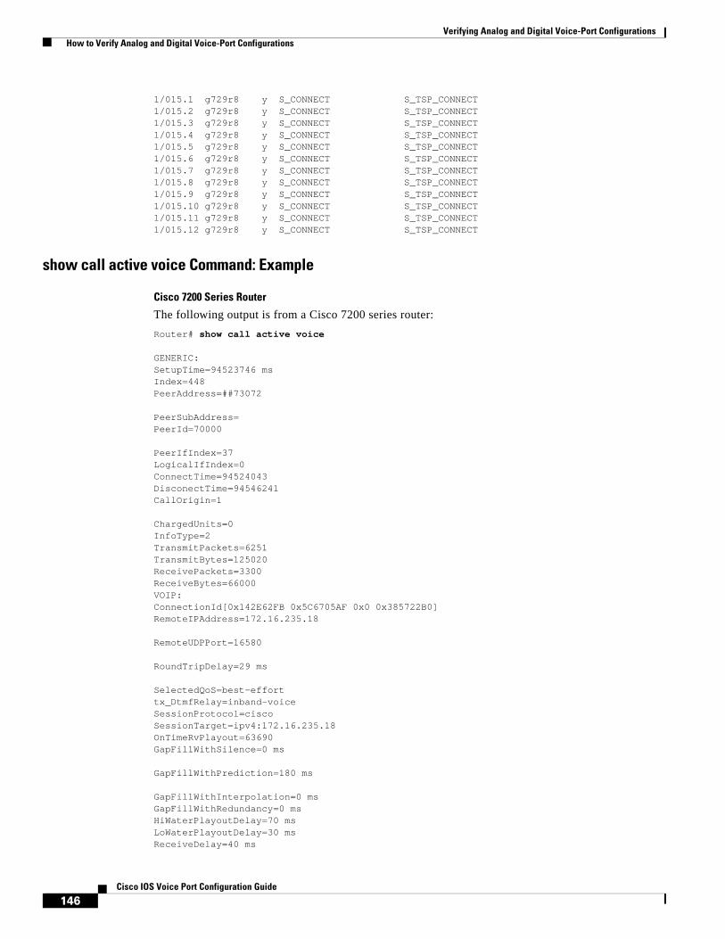
Verifying Analog and Digital Voice-Port Configurations How to Verify Analog and Digital Voice-Port Configurations
146Cisco IOS Voice Port Configuration Guide
1/015.1 g729r8 y S_CONNECT S_TSP_CONNECT 1/015.2 g729r8 y S_CONNECT S_TSP_CONNECT 1/015.3 g729r8 y S_CONNECT S_TSP_CONNECT 1/015.4 g729r8 y S_CONNECT S_TSP_CONNECT 1/015.5 g729r8 y S_CONNECT S_TSP_CONNECT 1/015.6 g729r8 y S_CONNECT S_TSP_CONNECT 1/015.7 g729r8 y S_CONNECT S_TSP_CONNECT 1/015.8 g729r8 y S_CONNECT S_TSP_CONNECT 1/015.9 g729r8 y S_CONNECT S_TSP_CONNECT 1/015.10 g729r8 y S_CONNECT S_TSP_CONNECT 1/015.11 g729r8 y S_CONNECT S_TSP_CONNECT 1/015.12 g729r8 y S_CONNECT S_TSP_CONNECT
show call active voice Command: Example
Cisco 7200 Series Router
The following output is from a Cisco 7200 series router:
Router# show call active voice
GENERIC:SetupTime=94523746 msIndex=448PeerAddress=##73072
PeerSubAddress=PeerId=70000
PeerIfIndex=37LogicalIfIndex=0ConnectTime=94524043DisconectTime=94546241CallOrigin=1
ChargedUnits=0InfoType=2TransmitPackets=6251TransmitBytes=125020ReceivePackets=3300ReceiveBytes=66000VOIP:ConnectionId[0x142E62FB 0x5C6705AF 0x0 0x385722B0]RemoteIPAddress=172.16.235.18
RemoteUDPPort=16580
RoundTripDelay=29 ms
SelectedQoS=best-efforttx_DtmfRelay=inband-voiceSessionProtocol=ciscoSessionTarget=ipv4:172.16.235.18OnTimeRvPlayout=63690GapFillWithSilence=0 ms
GapFillWithPrediction=180 ms
GapFillWithInterpolation=0 msGapFillWithRedundancy=0 msHiWaterPlayoutDelay=70 msLoWaterPlayoutDelay=30 msReceiveDelay=40 ms

Verifying Analog and Digital Voice-Port Configurations How to Verify Analog and Digital Voice-Port Configurations
147Cisco IOS Voice Port Configuration Guide
LostPackets=0 ms
EarlyPackets=1 ms
LatePackets=18 ms
VAD = disabled
CoderTypeRate=g729r8
CodecBytes=20
cvVoIPCallHistoryIcpif=0SignalingType=cas
show call history voice Command: Example
Cisco 7200 Series Router
The following output is from a Cisco 7200 series router:
Router# show call history voice
GENERIC:SetupTime=94893250 msIndex=450PeerAddress=##52258
PeerSubAddress=PeerId=50000
PeerIfIndex=35LogicalIfIndex=0DisconnectCause=10
DisconnectText=normal call clearing.
ConnectTime=94893780DisconectTime=95015500CallOrigin=1
ChargedUnits=0InfoType=2TransmitPackets=32258TransmitBytes=645160ReceivePackets=20061ReceiveBytes=401220VOIP:ConnectionId[0x142E62FB 0x5C6705B3 0x0 0x388F851C]RemoteIPAddress=172.16.235.18
RemoteUDPPort=16552
RoundTripDelay=23 ms
SelectedQoS=best-efforttx_DtmfRelay=inband-voiceSessionProtocol=ciscoSessionTarget=ipv4:172.16.235.18OnTimeRvPlayout=398000GapFillWithSilence=0 ms
GapFillWithPrediction=1440 ms

Verifying Analog and Digital Voice-Port Configurations How to Verify Analog and Digital Voice-Port Configurations
148Cisco IOS Voice Port Configuration Guide
GapFillWithInterpolation=0 msGapFillWithRedundancy=0 msHiWaterPlayoutDelay=97 msLoWaterPlayoutDelay=30 msReceiveDelay=49 msLostPackets=1 msEarlyPackets=1 ms
LatePackets=132 ms
VAD = disabled
CoderTypeRate=g729r8
CodecBytes=20cvVoIPCallHistoryIcpif=0
CCDE, CCENT, Cisco Eos, Cisco Lumin, Cisco StadiumVision, the Cisco logo, DCE, and Welcome to the Human Network are trademarks; Changing the Way We Work, Live, Play, and Learn is a service mark; and Access Registrar, Aironet, AsyncOS, Bringing the Meeting To You, Catalyst, CCDA, CCDP, CCIE, CCIP, CCNA, CCNP, CCSP, CCVP, Cisco, the Cisco Certified Internetwork Expert logo, Cisco IOS, Cisco Press, Cisco Systems, Cisco Systems Capital, the Cisco Systems logo, Cisco Unity, Collaboration Without Limitation, EtherFast, EtherSwitch, Event Center, Fast Step, Follow Me Browsing, FormShare, GigaDrive, HomeLink, Internet Quotient, IOS, iPhone, iQ Expertise, the iQ logo, iQ Net Readiness Scorecard, iQuick Study, IronPort, the IronPort logo, LightStream, Linksys, MediaTone, MeetingPlace, MGX, Networkers, Networking Academy, Network Registrar, PCNow, PIX, PowerPanels, ProConnect, ScriptShare, SenderBase, SMARTnet, Spectrum Expert, StackWise, The Fastest Way to Increase Your Internet Quotient, TransPath, WebEx, and the WebEx logo are registered trademarks of Cisco Systems, Inc. and/or its affiliates in the United States and certain other countries.
All other trademarks mentioned in this document or Website are the property of their respective owners. The use of the word partner does not imply a partnership relationship between Cisco and any other company. (0804R)
Any Internet Protocol (IP) addresses used in this document are not intended to be actual addresses. Any examples, command display output, and figures included in the document are shown for illustrative purposes only. Any use of actual IP addresses in illustrative content is unintentional and coincidental.
© 2008 Cisco Systems, Inc. All rights reserved.
Americas Headquarters:Cisco Systems, Inc., 170 West Tasman Drive, San Jose, CA 95134-1706 USA
© 2008 Cisco Systems, Inc. All rights reserved.
Troubleshooting Analog and Digital Voice Port Configurations
This chapter provides information to assist you in analyzing and troubleshooting voice port problems.
Troubleshooting ChartTable 1 lists some problems that you might encounter after configuring voice ports. It also provides some suggested remedies.
Table 1 Troubleshooting Voice Port Configurations
Problem Suggested Action
No connectivity Ping the associated IP address to confirm connectivity. If you cannot successfully ping your destination, refer to the Cisco IOS IP Configuration Guide.
No connectivity Enter the show controller t1 or show controller e1 command with the controller number for the voice port you are troubleshooting. This will tell you:
• If the controller is up. If it is not, use the no shutdown command to make it active.
• Whether alarms have been reported.
• What parameter values have been set for the controller (framing, clock source, line code, cable length). If these values do not match those of the telephony connection you are making, reconfigure the controller.
See the “show controller Command: Examples” section in the Verifying Analog and Digital Voice-Port Configurations chapter for output.

Troubleshooting Analog and Digital Voice Port Configurations
150Cisco IOS Voice Port Configuration Guide
No connectivity Enter the show voice port command with the voice port number that you are troubleshooting, which will tell you:
• If the voice port is up. If it is not, use the no shutdown command to make it active.
• What parameter values have been set for the voice port, including default values (these do not appear in the output for the show running-config command). If these values do not match those of the telephony connection you are making, reconfigure the voice port.
See the “show voice port Command: Examples” section in the Verifying Analog and Digital Voice-Port Configurations chapter for sample output.
Telephony device buzzes or does not ring
Use the show voice port command to confirm that the ring frequency command is configured correctly. It must match the connected telephony equipment and may be country-dependent.
Distorted speech Use the show voice port command to confirm the cptone keyword setting (also called region tone) is US.
Setting a wrong cptone could result in faulty voice reproduction during analog-to-digital or digital-to-analog conversions.
Music on hold is not heard Reduce the configured level for the music-threshold command.
Background noise is not heard Enable the comfort-noise command.
Long pauses occur in conversation; like speaking on a walkie-talkie
Overall delay is probably excessive; the standard for adequate voice quality is 150 milliseconds (ms) one-way transit delay. Measure delay by using ping tests at various times of the day with different network traffic loads. If delay must be reduced, areas to examine include propagation delay of signals between the sending and receiving endpoints, voice encoding delay, and the voice packetization time for various VoIP codecs.
Jerky or choppy speech Variable delay, or jitter, is being introduced by congestion in the packet network. Two possible remedies are to:
• Reduce the amount of congestion in your packet network. Pings between VoIP endpoints will give an idea of the round-trip delay of a link, which should never exceed 300 ms. Network queuing and dropped packets should also be examined.
• Increase the size of the jitter buffer with the playout-delay command. (Refer to the Cisco IOS Voice Troubleshooting and Monitoring Guide.)
Clipped or fuzzy speech • Reduce input gain. (Refer to the Cisco IOS Voice Troubleshooting and Monitoring Guide.)
• Change the voice activity detection (VAD) level. Sometimes VAD cuts the sound too early and the speaker's voice is clipped. You can also change the time that VAD waits for silence.
Table 1 Troubleshooting Voice Port Configurations (continued)
Problem Suggested Action
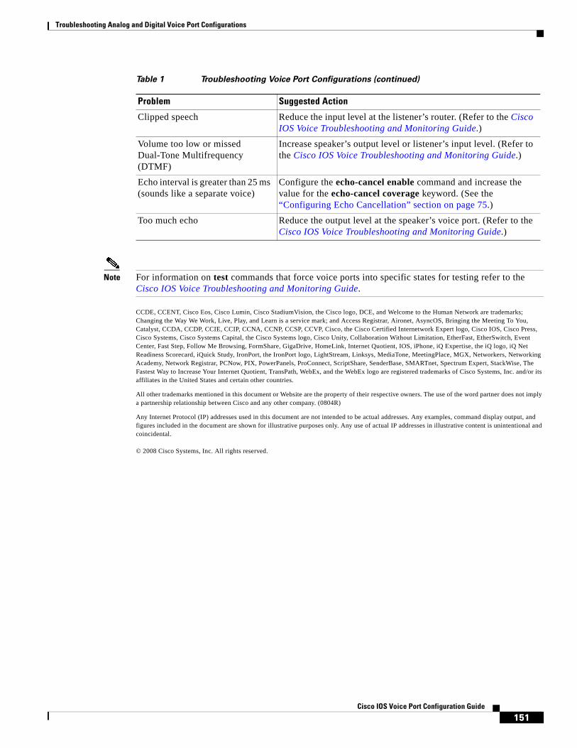
Troubleshooting Analog and Digital Voice Port Configurations
151Cisco IOS Voice Port Configuration Guide
Note For information on test commands that force voice ports into specific states for testing refer to the Cisco IOS Voice Troubleshooting and Monitoring Guide.
CCDE, CCENT, Cisco Eos, Cisco Lumin, Cisco StadiumVision, the Cisco logo, DCE, and Welcome to the Human Network are trademarks; Changing the Way We Work, Live, Play, and Learn is a service mark; and Access Registrar, Aironet, AsyncOS, Bringing the Meeting To You, Catalyst, CCDA, CCDP, CCIE, CCIP, CCNA, CCNP, CCSP, CCVP, Cisco, the Cisco Certified Internetwork Expert logo, Cisco IOS, Cisco Press, Cisco Systems, Cisco Systems Capital, the Cisco Systems logo, Cisco Unity, Collaboration Without Limitation, EtherFast, EtherSwitch, Event Center, Fast Step, Follow Me Browsing, FormShare, GigaDrive, HomeLink, Internet Quotient, IOS, iPhone, iQ Expertise, the iQ logo, iQ Net Readiness Scorecard, iQuick Study, IronPort, the IronPort logo, LightStream, Linksys, MediaTone, MeetingPlace, MGX, Networkers, Networking Academy, Network Registrar, PCNow, PIX, PowerPanels, ProConnect, ScriptShare, SenderBase, SMARTnet, Spectrum Expert, StackWise, The Fastest Way to Increase Your Internet Quotient, TransPath, WebEx, and the WebEx logo are registered trademarks of Cisco Systems, Inc. and/or its affiliates in the United States and certain other countries.
All other trademarks mentioned in this document or Website are the property of their respective owners. The use of the word partner does not imply a partnership relationship between Cisco and any other company. (0804R)
Any Internet Protocol (IP) addresses used in this document are not intended to be actual addresses. Any examples, command display output, and figures included in the document are shown for illustrative purposes only. Any use of actual IP addresses in illustrative content is unintentional and coincidental.
© 2008 Cisco Systems, Inc. All rights reserved.
Clipped speech Reduce the input level at the listener’s router. (Refer to the Cisco IOS Voice Troubleshooting and Monitoring Guide.)
Volume too low or missed Dual-Tone Multifrequency (DTMF)
Increase speaker’s output level or listener’s input level. (Refer to the Cisco IOS Voice Troubleshooting and Monitoring Guide.)
Echo interval is greater than 25 ms (sounds like a separate voice)
Configure the echo-cancel enable command and increase the value for the echo-cancel coverage keyword. (See the “Configuring Echo Cancellation” section on page 75.)
Too much echo Reduce the output level at the speaker’s voice port. (Refer to the Cisco IOS Voice Troubleshooting and Monitoring Guide.)
Table 1 Troubleshooting Voice Port Configurations (continued)
Problem Suggested Action

Troubleshooting Analog and Digital Voice Port Configurations
152Cisco IOS Voice Port Configuration Guide


![Horizontal stacking - CiscoConfigure a Switch Stack Configuring a Network Port as Stack Port Switch1(config)# switch 1 hstack-port 1 tenGigabitEthernet1/0/1 Do you want to continue?[confirm]](https://img.pdfslide.us/doc/110x75/5e417e3f84fc3d01570c1341/horizontal-stacking-cisco-configure-a-switch-stack-configuring-a-network-port.jpg)

![Horizontal stacking a Switch Stack Configuring a Network Port as Stack Port Switch1(config)# switch 1 hstack-port 1 tenGigabitEthernet1/0/1 Do you want to continue?[confirm] New Horizontal](https://img.pdfslide.us/doc/110x75/5ccaa80588c993e4388beee3/horizontal-stacking-a-switch-stack-configuring-a-network-port-as-stack-port-switch1config.jpg)