Embed Size (px)
Citation preview
VMware ContinuentArchitecture Overview
T E C H N I C A L W H I T E P A P E R
VMware Continuent
T E C H N I C A L W H I T E P A P E R / 2
Table of Contents
What is VMware Continuent? . . . . . . . . . . . . . . . . . . . . . . . . . . . . . . . . . . . . . . . . . . . 3
Overview . . . . . . . . . . . . . . . . . . . . . . . . . . . . . . . . . . . . . . . . . . . . . . . . . . . . . . . . . . . . . 4
Replications . . . . . . . . . . . . . . . . . . . . . . . . . . . . . . . . . . . . . . . . . . . . . . . . . . . . . . . . . . 4
Manager . . . . . . . . . . . . . . . . . . . . . . . . . . . . . . . . . . . . . . . . . . . . . . . . . . . . . . . . . . . . . 11
Connector . . . . . . . . . . . . . . . . . . . . . . . . . . . . . . . . . . . . . . . . . . . . . . . . . . . . . . . . . . . 12
Next Steps . . . . . . . . . . . . . . . . . . . . . . . . . . . . . . . . . . . . . . . . . . . . . . . . . . . . . . . . . . 22
VMware Contact Information . . . . . . . . . . . . . . . . . . . . . . . . . . . . . . . . . . . . . . . . . . 22
Providing Feedback . . . . . . . . . . . . . . . . . . . . . . . . . . . . . . . . . . . . . . . . . . . . . . . . . . 22
Additional Information . . . . . . . . . . . . . . . . . . . . . . . . . . . . . . . . . . . . . . . . . . . . . . . . 23
T E C H N I C A L W H I T E P A P E R / 3
VMware Continuent
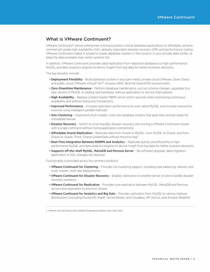
What is VMware Continuent?VMware Continuent® allows enterprises running business-critical database applications to affordably achieve commercial-grade high availability (HA), globally redundant disaster recovery (DR) and performance scaling. VMware Continuent makes it simple to create database clusters in the cloud or in your private data center, to keep the data available even when systems fail.
In addition, VMware Continuent provides data replication from relational databases to high-performance NoSQL and data analytics engines to derive insight from big data for better business decisions.
The key benefits include:
• Deployment Flexibility – Build database clusters in any bare-metal, private cloud (VMware, Open Stack) and public cloud (VMware vCloud® Air™, Amazon AWS, Red Hat OpenShift) environments.
• Zero-Downtime Maintenance – Perform database maintenance, such as schema changes, upgrades to a new version of MySQL or adding new hardware, without application or service interruptions.
• High Availability – Replace a failed master DBMS server within seconds while maintaining continuous availability and without losing any transactions.
• Improved Performance – Increase replication performance 5x over native MySQL and increase transaction volumes using intelligent parallel methods.1
• Geo-Clustering – Implement multi-master, cross-site database clusters that span sites and are ready for immediate failover.
• Disaster Recovery – Switch to a hot-standby disaster recovery site running a VMware Continuent cluster with a single command without losing application connectivity.
• Affordable Oracle Replication – Replicate data from Oracle to MySQL, from MySQL to Oracle, and from Oracle to Oracle. Think “Oracle GoldenGate without the price tag!”
• Real-Time Integration Between RDBMS and Analytics – Replicate quickly and efficiently to high-performance NoSQL and data analytics engines to derive insight from big data for better business decisions.
• Supports off-the-shelf MySQL, MariaDB and Percona Server – No software upgrade, data migration, application or DDL changes are required.
Functionality is provided across four primary products:
• VMware Continuent for Clustering – Provides full clustering support, including load balancing, failover, and multi-master, multi-site deployments.
• VMware Continuent for Disaster Recovery – Enables replication to another server or site to handle disaster recovery scenarios.
• VMware Continuent for Replication – Provides core replication between MySQL, MariaDB and Percona servers and replication to and from Oracle.
• VMware Continuent for Analytics and Big Data – Provides replication from MySQL to various Hadoop distributions (including Pivotal HD, MapR, HortonWorks, and Cloudera), HP Vertica, and Amazon Redshift.
1. VMware internal testing using 130GB/30 database sysbench test, April 2013
T E C H N I C A L W H I T E P A P E R / 4
VMware Continuent
FEATURE VMWARE CONTINUENT FOR CLUSTERING
VMWARE CONTINUENT FOR DISASTER RECOVERY
VMWARE CONTINUENT FOR REPLICATION
VMWARE CONTINUENT FOR ANALYTICS AND BIG DATA
Flexible MySQL Clustering Yes
Zero-Downtime Yes Yes
Automatic Failover Yes
Multi-Master, Multi-Site Yes Yes
Disaster Recovery Yes
Oracle Replication Yes
Replication To Real-Time Analytics And Big Data
Yes
Improved Performance Yes Yes
Supports MySQL, MariaDB and Percona Server
Yes Yes Yes Yes
OverviewVMware Continuent forms a collection of different products that provide specific areas of functionality. The overall product is actually made up of three key components that will work together to provide a fully managed, clustered solution for MySQL. The replication component also works in a standalone fashion to provide data replication between a number of replication targets.
ReplicationsThe replicator is a key component of VMware Continuent. It provides a powerful, but flexible, replication engine. The core is designed to take SQL statements and replicate them to another server verbatim, or to take row-based replication information and apply that into another database, either through forming suitable statements, or generating the content for native API calls to write the information into the database.
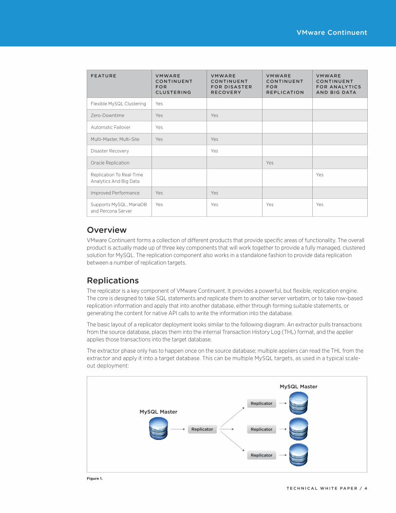
The basic layout of a replicator deployment looks similar to the following diagram. An extractor pulls transactions from the source database, places them into the internal Transaction History Log (THL) format, and the applier applies those transactions into the target database.
The extractor phase only has to happen once on the source database; multiple appliers can read the THL from the extractor and apply it into a target database. This can be multiple MySQL targets, as used in a typical scale-out deployment:
MySQL Master
MySQL Master
Replicator Replicator
Replicator
Replicator
Figure 1.
T E C H N I C A L W H I T E P A P E R / 5
VMware Continuent
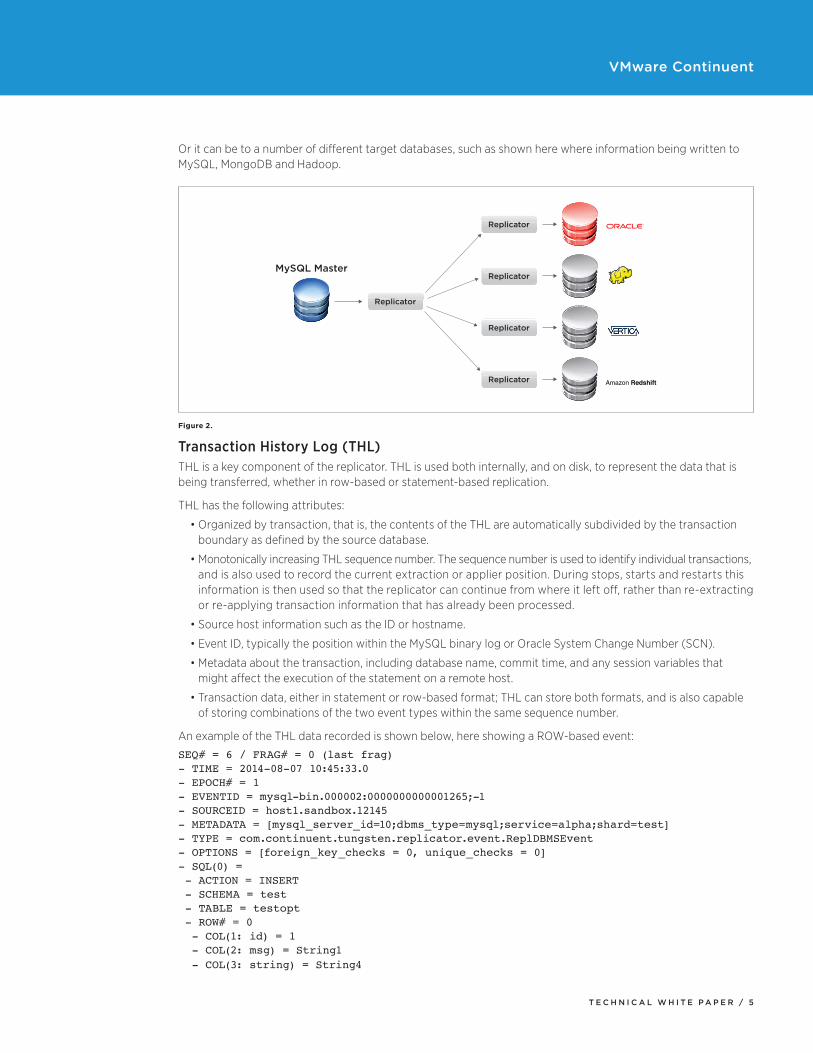
Or it can be to a number of different target databases, such as shown here where information being written to MySQL, MongoDB and Hadoop.
Replicator
Replicator
Replicator
Replicator
MySQL Master
Replicator
Amazon Redshift
Figure 2.
Transaction History Log (THL)THL is a key component of the replicator. THL is used both internally, and on disk, to represent the data that is being transferred, whether in row-based or statement-based replication.
THL has the following attributes:
• Organized by transaction, that is, the contents of the THL are automatically subdivided by the transaction boundary as defined by the source database.
• Monotonically increasing THL sequence number. The sequence number is used to identify individual transactions, and is also used to record the current extraction or applier position. During stops, starts and restarts this information is then used so that the replicator can continue from where it left off, rather than re-extracting or re-applying transaction information that has already been processed.
• Source host information such as the ID or hostname.
• Event ID, typically the position within the MySQL binary log or Oracle System Change Number (SCN).
• Metadata about the transaction, including database name, commit time, and any session variables that might affect the execution of the statement on a remote host.
• Transaction data, either in statement or row-based format; THL can store both formats, and is also capable of storing combinations of the two event types within the same sequence number.
An example of the THL data recorded is shown below, here showing a ROW-based event:
SEQ# = 6 / FRAG# = 0 (last frag)- TIME = 2014-08-07 10:45:33.0- EPOCH# = 1- EVENTID = mysql-bin.000002:0000000000001265;-1- SOURCEID = host1.sandbox.12145- METADATA = [mysql_server_id=10;dbms_type=mysql;service=alpha;shard=test]- TYPE = com.continuent.tungsten.replicator.event.ReplDBMSEvent- OPTIONS = [foreign_key_checks = 0, unique_checks = 0]- SQL(0) = - ACTION = INSERT - SCHEMA = test - TABLE = testopt - ROW# = 0 - COL(1: id) = 1 - COL(2: msg) = String1 - COL(3: string) = String4
T E C H N I C A L W H I T E P A P E R / 6
VMware Continuent
THL information is used internally by the replicator, is shared over the network (using port 2112 by default) to share the THL stored by this node with other replicators, and is stored on disk in THL files that contain the raw THL data. The on-disk files are not compressed or encrypted, and are automatically managed by the replicator, enabling the replicator to automatically store the last N days (or hours or minutes) of logs. This local storage is important when dealing with failover and master switches, as it ensures that the local host has a copy of the transactions to be applied.
ExtractorExtractors within the replicator read the information from a source database and translate the stored transactional information into THL so that it can be distributed to other replicators that read the information and apply the THL events to a local database.
Extractor For MySQLExtraction of information from a MySQL database, the key database environment for the replicator, involves directly reading the MySQL binary log. The MySQL binary log is used in native MySQL replication and provides a sequential record of all the statement or row changes (depending on the selected binary log format), including data definition statements made to the MySQL database.
In a native MySQL replication environment, the MySQL binary log is transferred over the network and applied to the target database just as if the statements were being generated locally. The binary log content is transferred over the network through a listener service within MySQL that serves up the content.
The extraction process works with MySQL v5.0 and up, and with MariaDB v5 and v10, and all third-party variants of the MySQL database such as Percona.
Because the data is read directly from the binary log, the statement or row based data is quickly converted into the THL format, and because it does not rely on a database connection for the extraction of the change data, there is low impact on the database itself (a small tracking table and administrator privileges are required for replication support), and no effects such as cache pollution that may be created when accessing data wholesale through a traditional SQL extraction method.
Extractor for OracleThe extractor within Oracle works with Oracle 10 or 11g, and works with both Standard Edition and Enterprise Edition. The method of extraction is through an internal service provided by the Oracle database called Change Data Capture (CDC). Within CDC, tables are created that mirror the live database tables, but which are used to store only the changes generated by standard operations. These changes are ‘published’ into these CDC tables, and then the replicator ‘subscribes’ to the CDC tables and extracts the changes and writes that information to the THL format. Because of the way in which the data is captured and stored, all Oracle extraction occurs using row-based operations.
The method used internally by Oracle CDC to generate the change information depends on the edition of Oracle used. Standard Edition supports only synchronous CDC; Enterprise Edition supports both synchronous and asynchronous CDC. The two methods work differently, with different impact on the Oracle system:
• Synchronous CDC works by creating triggers on each source table that are fired during an insert or update operation updating the CDC table with the changes. This method implies a small overhead to the Oracle application updating the table due to the trigger execution.
• Asynchronous CDC works through a separate process that consumes the changes recorded within the Oracle Redo Logs, creating the corresponding changes within the CDC tables in the process. Unlike synchronous CDC, there can be a small delay as the changes are processed and published.
Once the data has been extracted and written into the VMware Continuent THL format, the fact that the changes are recorded as row-changes means that the data can be written to any target database. Note that only the data is replicated. The CDC extraction method does not expose DDL changes, so modifications to the schema must be made by hand or by using the ddlscan tool.
T E C H N I C A L W H I T E P A P E R / 7
VMware Continuent
Internal PipelinesWithin the replicator itself are a number of configured pipelines. These are used to move data from one location to another, for example, from the MySQL binary log into the in-memory THL format, or from the in-memory format to the on-disk THL storage.
These pipelines are important because they enable data to be loaded from extractors, disk, or memory-based queues, and ultimately applied into any system using a suitable applier.
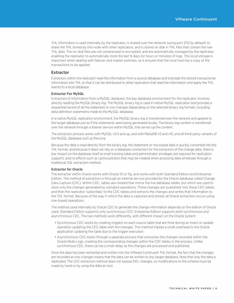
For example, the typical ‘master’ based pipeline, reading data from a source database and writing it into THL looks like this:
Dataserver Memory Q
binlog-to-q stage q-to-thl stage
THL
Extract Filter Apply Extract Filter Apply
Figure 3.
• Data is extracted from the source database
• Data is translated into memory-based THL
• Data is transferred from memory into on-disk THL
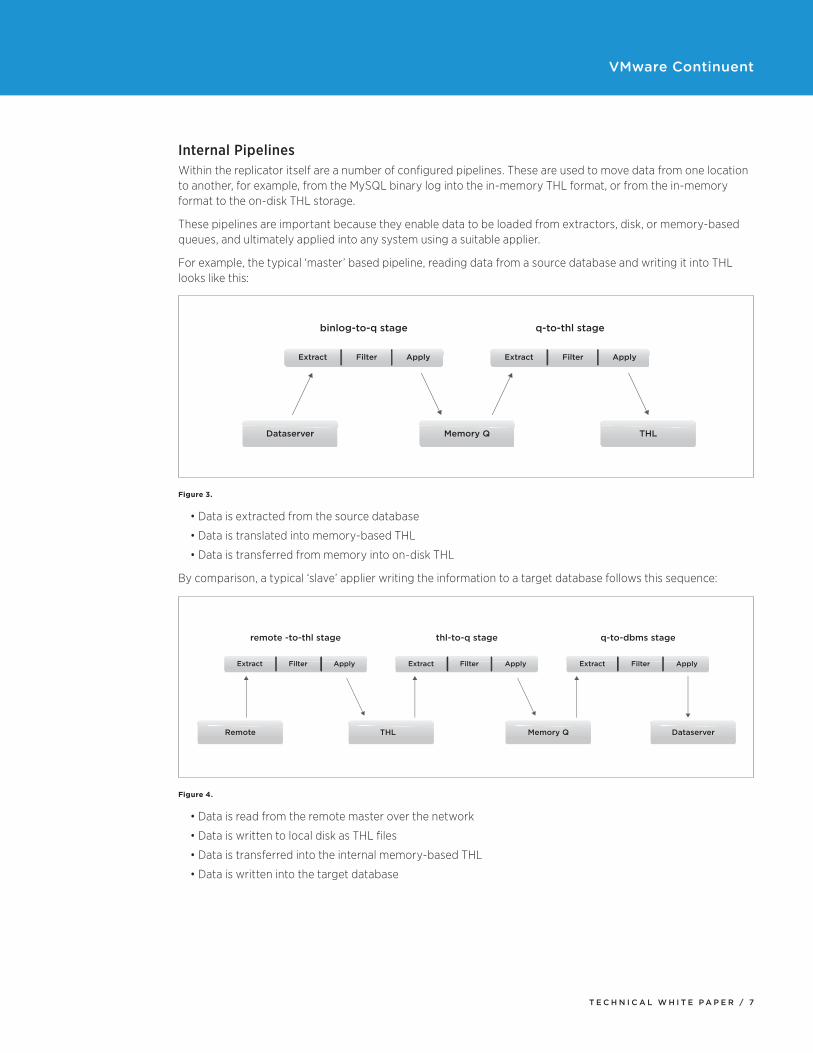
By comparison, a typical ‘slave’ applier writing the information to a target database follows this sequence:
Remote THL Memory Q Dataserver
remote -to-thl stage
Extract Filter Apply
thl-to-q stage
Extract Filter Apply
q-to-dbms stage
Extract Filter Apply
Figure 4.
• Data is read from the remote master over the network
• Data is written to local disk as THL files
• Data is transferred into the internal memory-based THL
• Data is written into the target database
T E C H N I C A L W H I T E P A P E R / 8
VMware Continuent
FiltersWithin each of the pipeline stages above, filters can be added into the pipeline. The role and purpose of these filters depends on your requirements. For example, filters can be applied that filter out certain columns, tables, or databases; others can rename tables, and others can extend or expand on the information stored in the THL, for example, adding primary key information or column names.
All filters are optional, but for effective heterogeneous replication, certain information must be added to the THL to ensure that the data is in a format suitable to be applied into a ‘foreign’ database, which may not have either the same schema layout or row-based insertion support.
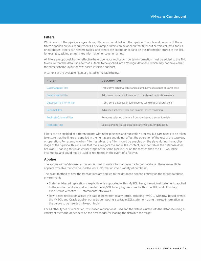
A sample of the available filters are listed in the table below.
FILTER DESCRIPTION
CaseMappingFilter Transforms schema, table and column names to upper or lower case
ColumnNameFilter Adds column name information to row-based replication events
DatabaseTransformFilter Transforms database or table names using regular expressions
RenameFilter Advanced schema, table and column-based renaming
ReplicateColumnsFilter Removes selected columns from row-based transaction data
ReplicateFilter Selects or ignores specification schemas and/or databases
Filters can be enabled at different points within the pipelines and replication process, but care needs to be taken to ensure that the filters are applied in the right place and do not affect the operation of the rest of the topology or operation. For example, when filtering tables, the filter should be enabled on the slave during the applier stage of the pipeline; this ensures that the slave gets the entire THL content, even for tables the database does not want. Enabling this in an earlier stage of the same pipeline, or on the master, then the THL would be incomplete and could not be used or redirected in the event of a failover.
ApplierThe applier within VMware Continuent is used to write information into a target database. There are multiple appliers available that can be used to write information into a variety of databases.
The exact method of how the transactions are applied to the database depend entirely on the target database environment:
• Statement-based replication is explicitly only supported within MySQL. Here, the original statements applied to the master database and written to the MySQL binary log are stored within the THL, and ultimately executed as verbatim SQL statements into slaves.
• Row-based replication allows the data to be written to any target, including MySQL. With row-based events, the MySQL and Oracle applier works by composing a suitable SQL statement using the row-information as the values to be inserted into each table.
For all other types of replication, row-based replication is used and the data is written into the database using a variety of methods, dependent on the best model for loading the data into the target.
T E C H N I C A L W H I T E P A P E R / 9
VMware Continuent
Replication InterfaceThe replicator includes a number of tools that can be used to monitor and control the replication process, and extract information about the replicated data.
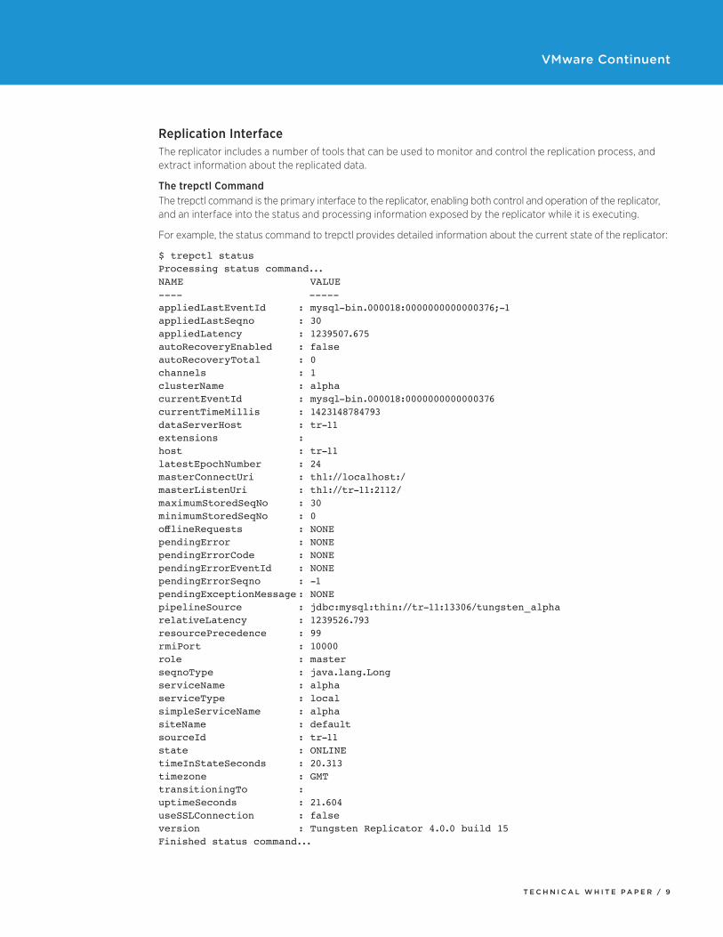
The trepctl CommandThe trepctl command is the primary interface to the replicator, enabling both control and operation of the replicator, and an interface into the status and processing information exposed by the replicator while it is executing.
For example, the status command to trepctl provides detailed information about the current state of the replicator:
$ trepctl statusProcessing status command...NAME VALUE---- -----appliedLastEventId : mysql-bin.000018:0000000000000376;-1appliedLastSeqno : 30appliedLatency : 1239507.675autoRecoveryEnabled : falseautoRecoveryTotal : 0channels : 1clusterName : alphacurrentEventId : mysql-bin.000018:0000000000000376currentTimeMillis : 1423148784793dataServerHost : tr-11extensions : host : tr-11latestEpochNumber : 24masterConnectUri : thl://localhost:/masterListenUri : thl://tr-11:2112/maximumStoredSeqNo : 30minimumStoredSeqNo : 0offlineRequests :NONEpendingError : NONEpendingErrorCode : NONEpendingErrorEventId : NONEpendingErrorSeqno : -1pendingExceptionMessage : NONEpipelineSource : jdbc:mysql:thin://tr-11:13306/tungsten_alpharelativeLatency : 1239526.793resourcePrecedence : 99rmiPort : 10000role : masterseqnoType : java.lang.LongserviceName : alphaserviceType : localsimpleServiceName : alphasiteName : defaultsourceId : tr-11state : ONLINEtimeInStateSeconds : 20.313timezone : GMTtransitioningTo : uptimeSeconds : 21.604useSSLConnection : falseversion : Tungsten Replicator 4.0.0 build 15Finished status command...
T E C H N I C A L W H I T E P A P E R / 1 0
VMware Continuent
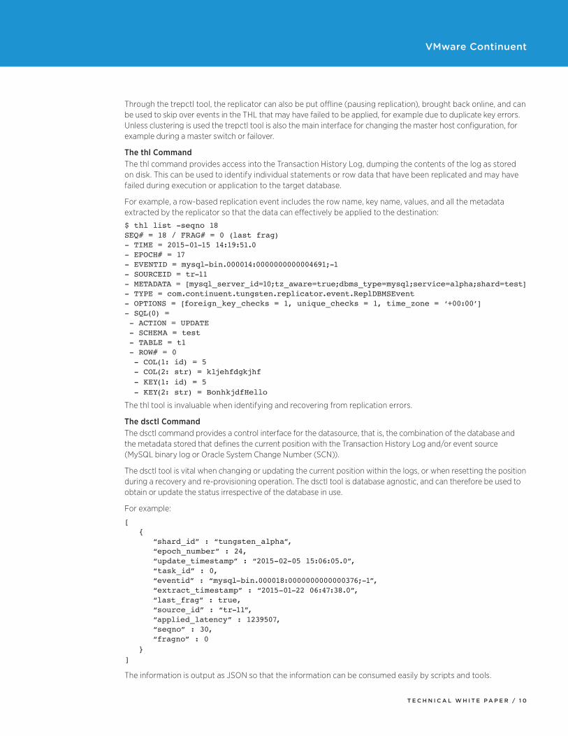
Through the trepctl tool, the replicator can also be put offline (pausing replication), brought back online, and can be used to skip over events in the THL that may have failed to be applied, for example due to duplicate key errors. Unless clustering is used the trepctl tool is also the main interface for changing the master host configuration, for example during a master switch or failover.
The thl CommandThe thl command provides access into the Transaction History Log, dumping the contents of the log as stored on disk. This can be used to identify individual statements or row data that have been replicated and may have failed during execution or application to the target database.
For example, a row-based replication event includes the row name, key name, values, and all the metadata extracted by the replicator so that the data can effectively be applied to the destination:
$ thl list -seqno 18SEQ# = 18 / FRAG# = 0 (last frag)- TIME = 2015-01-15 14:19:51.0- EPOCH# = 17- EVENTID = mysql-bin.000014:0000000000004691;-1- SOURCEID = tr-11- METADATA = [mysql_server_id=10;tz_aware=true;dbms_type=mysql;service=alpha;shard=test]- TYPE = com.continuent.tungsten.replicator.event.ReplDBMSEvent- OPTIONS = [foreign_key_checks = 1, unique_checks = 1, time_zone = ‘+00:00’]- SQL(0) = - ACTION = UPDATE - SCHEMA = test - TABLE = t1 - ROW# = 0 - COL(1: id) = 5 - COL(2: str) = kljehfdgkjhf - KEY(1: id) = 5 - KEY(2: str) = BonhkjdfHello
The thl tool is invaluable when identifying and recovering from replication errors.
The dsctl CommandThe dsctl command provides a control interface for the datasource, that is, the combination of the database and the metadata stored that defines the current position with the Transaction History Log and/or event source (MySQL binary log or Oracle System Change Number (SCN)).
The dsctl tool is vital when changing or updating the current position within the logs, or when resetting the position during a recovery and re-provisioning operation. The dsctl tool is database agnostic, and can therefore be used to obtain or update the status irrespective of the database in use.
For example:
[ { “shard_id” : “tungsten_alpha”, “epoch_number” : 24, “update_timestamp” : “2015-02-05 15:06:05.0”, “task_id” : 0, “eventid” : “mysql-bin.000018:0000000000000376;-1”, “extract_timestamp” : “2015-01-22 06:47:38.0”, “last_frag” : true, “source_id” : “tr-11”, “applied_latency” : 1239507, “seqno” : 30, “fragno” : 0 }]
The information is output as JSON so that the information can be consumed easily by scripts and tools.
T E C H N I C A L W H I T E P A P E R / 1 1
VMware Continuent
ManagerThe manager forms a crucial part of the overall cluster service. It stays in constant contact with both the connector and replicator services and has a number of key responsibilities related to the way the cluster operates.
These include, but are not limited to:
• Monitoring the replication service on each machine.
• Monitoring the physical access to each machine.
• Monitoring the physical execution and availability of the MySQL service. In the event of a failure, the manager is capable of starting the MySQL service.
• Controlling the state and role of each node in the network.
• Controlling the topology and configuration of the nodes.
• Handling failover in the event of a MySQL or node failure, switching masters and redirecting slave configuration.
• Communicating the current configuration and topology to the connectors.
• Making group (cluster-wide) decisions, for example, when electing the
• Handling manual switches during maintenance processes.
• Handling recovery, both automatic and manual to bring a node back into working operation.
• Providing an interface to the cluster configuration and control systems.
At any one time, only one node within the cluster is designated as the coordinator. The coordinator is automatically elected within the cluster. The coordinator for a cluster may not be the same node as the master.
RulesThe manager operation and process is entirely controlled by a set of rules that decide the exact, and correct, operation of the cluster and the steps required to handle a specific operation. These rules are extensive and handle all of the situations that the manager is responsible for controlling, including failed MySQL servers, replication management and failures and failovers. These rules are designed to recover and return the cluster back into an operational state.
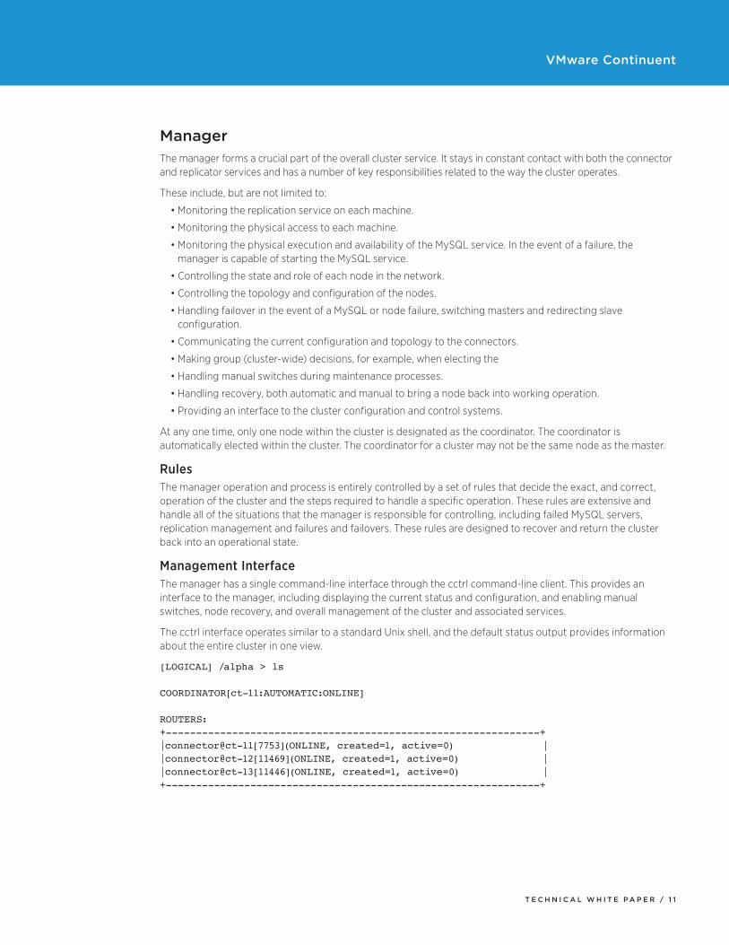
Management InterfaceThe manager has a single command-line interface through the cctrl command-line client. This provides an interface to the manager, including displaying the current status and configuration, and enabling manual switches, node recovery, and overall management of the cluster and associated services.
The cctrl interface operates similar to a standard Unix shell, and the default status output provides information about the entire cluster in one view.
[LOGICAL] /alpha > ls
COORDINATOR[ct-11:AUTOMATIC:ONLINE]
ROUTERS:+--------------------------------------------------------------+|connector@ct-11[7753](ONLINE, created=1, active=0) | |connector@ct-12[11469](ONLINE, created=1, active=0) ||connector@ct-13[11446](ONLINE, created=1, active=0) |+--------------------------------------------------------------+
T E C H N I C A L W H I T E P A P E R / 1 2
VMware Continuent
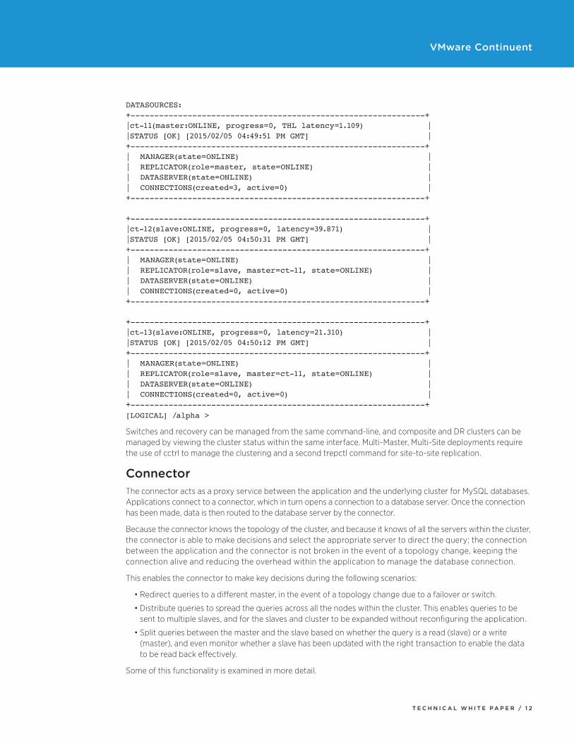
DATASOURCES:+--------------------------------------------------------------+|ct-11(master:ONLINE, progress=0, THL latency=1.109) ||STATUS [OK] [2015/02/05 04:49:51 PM GMT] |+--------------------------------------------------------------+| MANAGER(state=ONLINE) || REPLICATOR(role=master, state=ONLINE) || DATASERVER(state=ONLINE) || CONNECTIONS(created=3, active=0) |+--------------------------------------------------------------+
+--------------------------------------------------------------+|ct-12(slave:ONLINE, progress=0, latency=39.871) ||STATUS [OK] [2015/02/05 04:50:31 PM GMT] |+--------------------------------------------------------------+| MANAGER(state=ONLINE) || REPLICATOR(role=slave, master=ct-11, state=ONLINE) || DATASERVER(state=ONLINE) || CONNECTIONS(created=0, active=0) |+--------------------------------------------------------------+
+--------------------------------------------------------------+|ct-13(slave:ONLINE, progress=0, latency=21.310) ||STATUS [OK] [2015/02/05 04:50:12 PM GMT] |+--------------------------------------------------------------+| MANAGER(state=ONLINE) || REPLICATOR(role=slave, master=ct-11, state=ONLINE) || DATASERVER(state=ONLINE) || CONNECTIONS(created=0, active=0) |+--------------------------------------------------------------+[LOGICAL] /alpha >
Switches and recovery can be managed from the same command-line, and composite and DR clusters can be managed by viewing the cluster status within the same interface. Multi-Master, Multi-Site deployments require the use of cctrl to manage the clustering and a second trepctl command for site-to-site replication.
ConnectorThe connector acts as a proxy service between the application and the underlying cluster for MySQL databases. Applications connect to a connector, which in turn opens a connection to a database server. Once the connection has been made, data is then routed to the database server by the connector.
Because the connector knows the topology of the cluster, and because it knows of all the servers within the cluster, the connector is able to make decisions and select the appropriate server to direct the query; the connection between the application and the connector is not broken in the event of a topology change, keeping the connection alive and reducing the overhead within the application to manage the database connection.
This enables the connector to make key decisions during the following scenarios:
• Redirect queries to a different master, in the event of a topology change due to a failover or switch.
• Distribute queries to spread the queries across all the nodes within the cluster. This enables queries to be sent to multiple slaves, and for the slaves and cluster to be expanded without reconfiguring the application.
• Split queries between the master and the slave based on whether the query is a read (slave) or a write (master), and even monitor whether a slave has been updated with the right transaction to enable the data to be read back effectively.
Some of this functionality is examined in more detail.
T E C H N I C A L W H I T E P A P E R / 1 3
VMware Continuent
Because of the authentication built into the MySQL protocol, the connector makes use of a user map, this stores usernames and password information that enables the connector to open connectors to the MySQL servers and accept and authenticate connections from clients without triggering a man-in-the-middle type security attach.
The user map requirement may be removed but the connector will not be able to automatically reconnect to the new master. The application must have reconnect logic built in or allow for disconnection errors to be properly handled. Disabling the user map also disables the ability to support transparent read/write splitting. The port-based read/write splitting may still be enabled. See bridge mode below for more information.
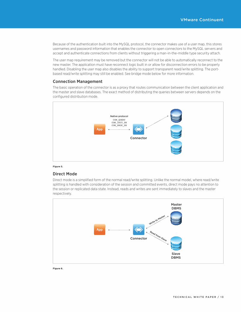
Connection ManagementThe basic operation of the connector is as a proxy that routes communication between the client application and the master and slave databases. The exact method of distributing the queries between servers depends on the configured distribution mode.
Native protocolCOM_QUERY
COM_INIT_DBCOM_DROP_DB
Connector
App
Figure 5.
Direct ModeDirect mode is a simplified form of the normal read/write splitting. Unlike the normal model, where read/write splitting is handled with consideration of the session and committed events, direct mode pays no attention to the session or replicated data state. Instead, reads and writes are sent immediately to slaves and the master respectively.
MasterDBMS
Connector
SlaveDBMS
App
Write to
Master
Read from Slave
Figure 6.
T E C H N I C A L W H I T E P A P E R / 1 4
VMware Continuent
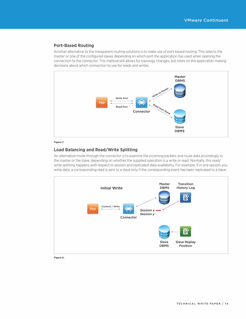
Port-Based RoutingAnother alternative to the transparent routing solutions is to make use of port-based routing. This selects the master or one of the configured slaves depending on which port the application has used when opening the connection to the connector. This method still allows for topology changes, but relies on the application making decisions about which connection to use for reads and writes.
MasterDBMS
Connector
SlaveDBMS
AppWrite Port Write
to Maste
r
Read from Slave
Read Port
Figure 7.
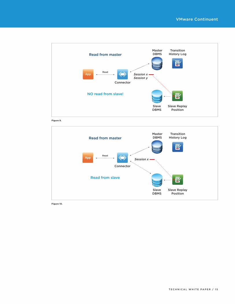
Load Balancing and Read/Write SplittingAn alternative mode through the connector is to examine the incoming packets and route data accordingly to the master or the slave, depending on whether the supplied operation is a write or read. Normally, this read/write splitting happens with respect to session and replicated data availability. For example, if in one session you write data, a corresponding read is sent to a slave only if the corresponding event has been replicated to a slave.
MasterDBMSInitial Write
TransitionHistory Log
Slave ReplayPosition
Connector
Session xSession y
SlaveDBMS
AppConnect / Write
Figure 8.
T E C H N I C A L W H I T E P A P E R / 1 5
VMware Continuent
MasterDBMSRead from master
NO read from slave!
TransitionHistory Log
Slave ReplayPosition
Connector
Session xSession y
SlaveDBMS
AppRead
Figure 9.
MasterDBMSRead from master
Read from slave
TransitionHistory Log
Slave ReplayPosition
Connector
Session x
SlaveDBMS
AppRead
Figure 10.
T E C H N I C A L W H I T E P A P E R / 1 6
VMware Continuent
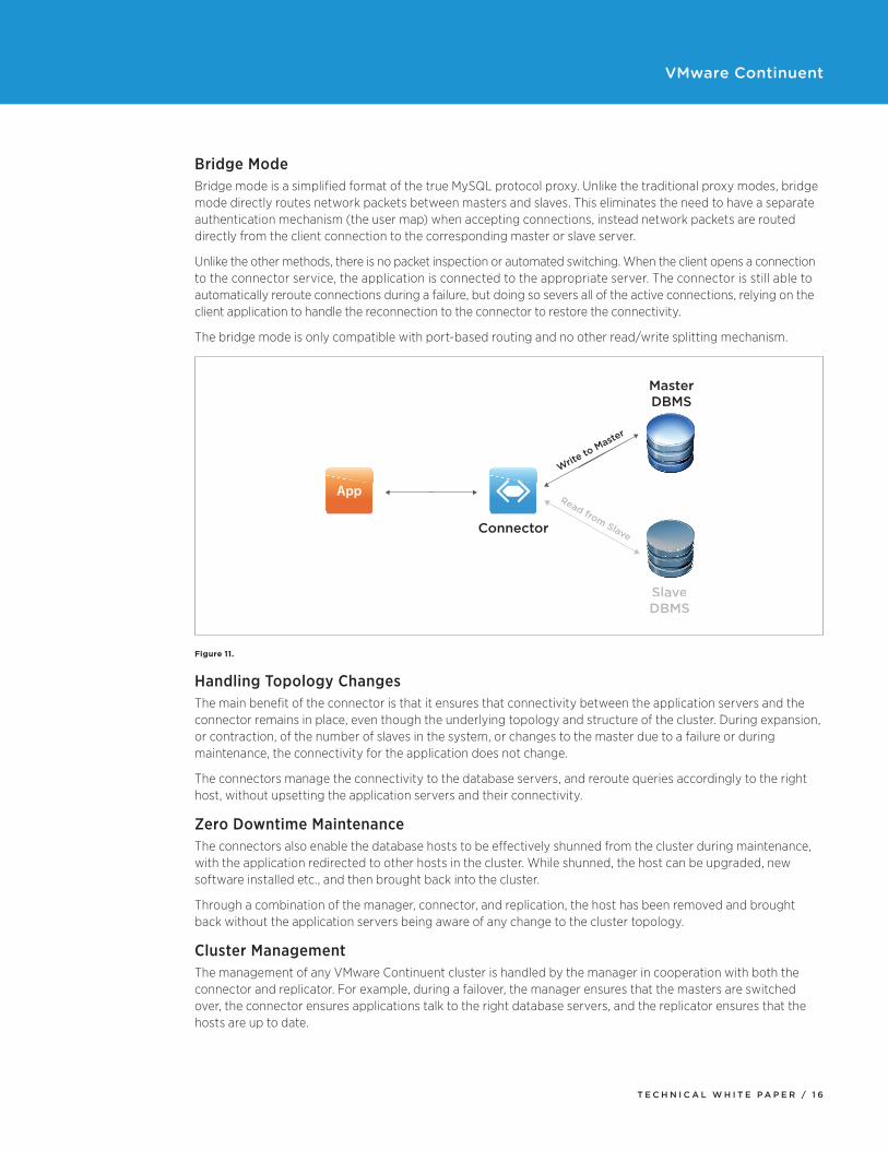
Bridge ModeBridge mode is a simplified format of the true MySQL protocol proxy. Unlike the traditional proxy modes, bridge mode directly routes network packets between masters and slaves. This eliminates the need to have a separate authentication mechanism (the user map) when accepting connections, instead network packets are routed directly from the client connection to the corresponding master or slave server.
Unlike the other methods, there is no packet inspection or automated switching. When the client opens a connection to the connector service, the application is connected to the appropriate server. The connector is still able to automatically reroute connections during a failure, but doing so severs all of the active connections, relying on the client application to handle the reconnection to the connector to restore the connectivity.
The bridge mode is only compatible with port-based routing and no other read/write splitting mechanism.
MasterDBMS
Connector
SlaveDBMS
App
Write to
Master
Read from Slave
Figure 11.
Handling Topology ChangesThe main benefit of the connector is that it ensures that connectivity between the application servers and the connector remains in place, even though the underlying topology and structure of the cluster. During expansion, or contraction, of the number of slaves in the system, or changes to the master due to a failure or during maintenance, the connectivity for the application does not change.
The connectors manage the connectivity to the database servers, and reroute queries accordingly to the right host, without upsetting the application servers and their connectivity.
Zero Downtime MaintenanceThe connectors also enable the database hosts to be effectively shunned from the cluster during maintenance, with the application redirected to other hosts in the cluster. While shunned, the host can be upgraded, new software installed etc., and then brought back into the cluster.
Through a combination of the manager, connector, and replication, the host has been removed and brought back without the application servers being aware of any change to the cluster topology.
Cluster ManagementThe management of any VMware Continuent cluster is handled by the manager in cooperation with both the connector and replicator. For example, during a failover, the manager ensures that the masters are switched over, the connector ensures applications talk to the right database servers, and the replicator ensures that the hosts are up to date.
T E C H N I C A L W H I T E P A P E R / 1 7
VMware Continuent
Automatic FailoverThe manager provides automatic failover by monitoring the servers and replication process. If a slave fails, for example due to a database software or hardware failure, the slave is automatically ‘shunned’ from the cluster to prevent the host being used by applications, which includes removing the node from the active list for the connector.
In the event of a master failure, the manager performs a series of steps to ensure that the database is switched:
1. Identifies the most up to date slave
2. Connectors shut down connections to the current master
3. Disables the current master replication
4. Pauses replication on all current slaves
5. Makes the most up to date slave the new master
6. Update the connectors with the new master
7. Connectors allow connections to the new master
8. Updates the slaves to point to the new master for replication
9. Restarts replication on all slaves
10. Updates the connector node map with the complete topology
This ensures that the switch is the most effective and with the minimum downtime while ensuring there is no data loss from those transactions already committed to disk on the master are written to the slave before the replication switch. Throughout the switch procedure, slave databases can continue to service read-requests; and applications can continue running even though the cluster is in a reduced state.
Manual FailoverA manual failure can be performed at any time, either by explicitly failing the master (which triggers the automatic failover outlined above), or by performing a manual switch. The manual switch follows the same basic process as outlined above, while taking account of the replication state and ensuring that the switch takes place in a safe fashion to ensure that no data is lost as the replication is moved from one host to another.
Recovery ProceduresRecovery of a failed datasource can be handled automatically by the manager. The manager will identify what steps are required to recover the datasource, including restarting the MySQL database, replication and other services. Because the replication status can be identified and tracked through unique THL sequence number, the replicator is able to restart from the failed position and catch up to the current replication state of the master. In situations where the replication is not able to continue, or the replication has become unsynchronized from the master, tools are available to re-provision a slave from an existing database so that replication can continue from a known state.
Online MaintenanceOnline maintenance is a feature that makes use of the ability to temporarily shun nodes from the cluster. When a node has been shunned, replication is stopped, and the connector stops sending queries to that host. This allows various operations to be performed on the host, including database schema, software, or hardware upgrades. Once the operation on the specific host has been completed, the node can be brought back into the cluster, and replication allowed to catch up to the current state.
A special policy, maintenance, ensures that the operations you are performing do not trigger the automated recovery or switch procedures. In a typical three-node cluster (one master, two slaves), maintenance for the entire cluster would follow this basic sequence:
1. Set maintenance policy
2. Shun slave host2
3. Perform maintenance
4. Validate the host2 server configuration
5. Recover the slave host2 back
T E C H N I C A L W H I T E P A P E R / 1 8
VMware Continuent
6. Ensure the slave (host2) has caught up
7. Shun slave host3
8. Perform maintenance
9. Validate the host3 server configuration
10. Recover slave host3 back
11. Ensure the slave (host3) has caught up
12. Switch master to host2
13. Shun host1
14. Perform maintenance
15. Validate the host1 server configuration
16. Recover the slave host1 back
17. Ensure the slave (host1) has caught up
18. Switch master back to host1
19. Set automatic policy
Providing this sequence is followed, the maintenance can be either database maintenance, such as creating indexes or restructuring tables, or even operating system and hardware upgrades. Because the process is managed, replication can be paused or stopped entirely and then each slave can ‘catch-up’ from the paused state to be an active part of the cluster.
Data Warehouses and the Batch ApplierThe batch applier is a general purpose engine for constructing the row-based event information and converting it into a CSV format that can then be used by later stages in the replicator to write the CSV information into a target database.
For example, the batch applier is used with the JavaScript applier engine to generate CSV files that are then used by the JavaScript process to load the information into Vertica, RedShift, and Hadoop. The same principles can also be used and applied so that the information can be written into other databases using the same method.
The focus with the batch applier is the process of composing the CSV files. The role of the CSV is not to contain the raw data, but instead to contain a representation of the change data that has been captured by the extractor. To achieve this, each CSV is created following a set pattern. The row data for each operation, INSERT, UPDATE or DELETE, is recorded in the CSV file verbatim.
Each row is also prefixed by the following four fields:
• Operation Type: Either I (Insert), U (Update), or D (Delete)
• THL Sequence Number: The unique transaction ID which can be used to identify the transaction (and therefore group of transactions) that caused this row update.
• Primary Key ID: The primary key from the source table that identifies this row. This information can be used to identify the unique row updated and is used when writing the new row data.
• Commit time: The time the original row was committed into the source database.
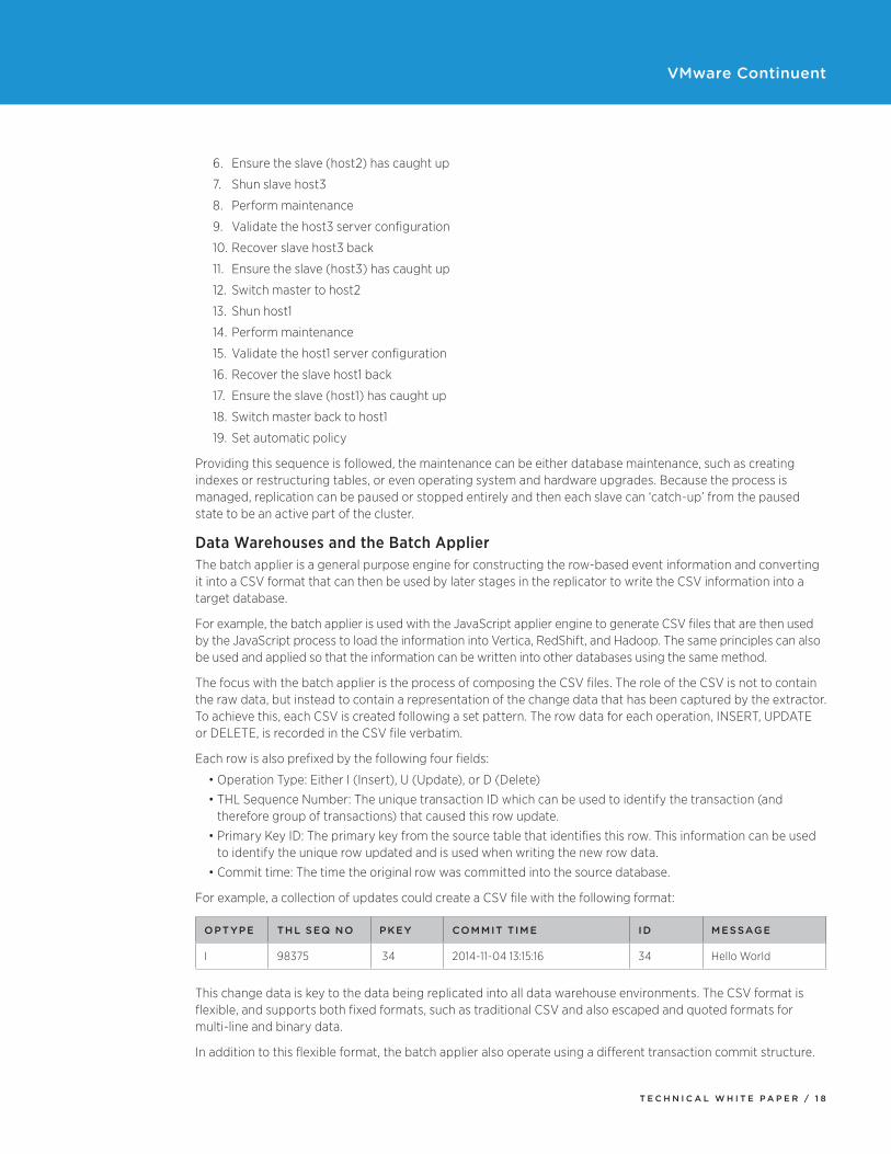
For example, a collection of updates could create a CSV file with the following format:
OPTYPE THL SEQ NO PKEY COMMIT TIME ID MESSAGE
I 98375 34 2014-11-04 13:15:16 34 Hello World
This change data is key to the data being replicated into all data warehouse environments. The CSV format is flexible, and supports both fixed formats, such as traditional CSV and also escaped and quoted formats for multi-line and binary data.
In addition to this flexible format, the batch applier also operate using a different transaction commit structure.
T E C H N I C A L W H I T E P A P E R / 1 9
VMware Continuent
JavaScript ApplierFor writing information into a variety of data warehouse environments, the quickest method is to generate batches of data into CSV and then use the native tools with each environment to import and update the information.
The JavaScript applier is a general purpose engine that enables the process of copying and importing data into a data warehouse or other database much easier. The JavaScript applier works by supporting the definition of five specific steps during the process of replicating data:
• Prepare – steps executed when the replicator goes online.• Begin – steps to be executed before a transaction has been committed.• Apply – steps to be executed while the transaction is being processed; typically this is where a CSV file is
copied and/or loaded into a target system.• Commit – called when the transaction has been completed.• Release – Called when the replicator goes offline.
The JavaScript environment enables use both of standard JavaScript constructs and language elements, but also includes support for the following extensions to the core JavaScript language:
• Ability to execute arbitrary command-line statements• Ability to access the native Java objects and constructs, including database connections. • Ability to access JDBC connections to specific databases.
The result is a flexible and adaptable environment that enables new appliers into target databases to be written and created very quickly.
HP Vertica ApplierThe HP Vertica applier makes use of the JavaScript applier and a native JDBC interface to the Vertica instance to load data into the database. A provided tool, ddlscan, enables the DDL from MySQL to be translated into a format suitable for building tables within the target environment. The ddlscan tool is used in all heterogeneous deployments to provide this DDL translation support and is a key part of the flexibility of the replication system. The ddlscan tool itself translates the source table structure into two different targets:
• A staging table; this contains all the fields of the original source table, plus the batch specific fields containing the operation type, THL sequence, primary key ID and commit time.
• A base table; this matches the definition of the source table completely. Data will ultimately be loaded into these base tables provide a carbon copy version of the information as written into the source tables.
The staging table is populated with information from the CSV generated by the batch applier, and then merged together to create the base tables, which will contain a carbon copy of the information.
The actual loading process works as follows:
• CSV Files are created using the batch applier per database/table.
• CSV Files are loaded into staging tables within Vertica using the native cpimport tool.
• Data is merged by deleting records, updating records, or inserting records within the ‘base’ tables using the change information recorded in the staging tables. This is achieved by executing suitable SQL statements, choosing the ‘last’ row (according to transaction ID) so that only the latest information is updated.
• Staging table data is deleted.
Using this method data is loaded efficiently in batches into Vertica, which is more efficient at loading large groups of information into tables, with the change data merged into the final tables.
T E C H N I C A L W H I T E P A P E R / 2 0
VMware Continuent
Amazon Redshift ApplierAmazon Redshift can ingest large volumes of data if the data has first been uploaded to the Amazon S3 storage area. This is combined with the same base and stating table architecture used in other data warehouse loaders.
The Amazon Redshift therefore makes use of the s3tools kit that enables easy uploading of data into S3, and combines this with a JDBC connection to the Redshift service. The resulting service works as follows:
• CSV Files are created using the batch applier per database/table.
• CSV Files are loaded into S3 using the s3tools.
• Using the JDBC interface, the CSV files containing the change data are loaded into staging tables within Redshift.
• Data is then merged from the staging tables into the base tables by deleting records, updating records, or inserting records within the ‘base’ tables using the change information recorded in the staging tables.
• Staging table data is deleted.
Using this method, data is loaded efficiently in batches into Redshift creating the same carbon copy tables, while taking advantage of the native S3 loading and ingestion offered by the Redshift engine.
Hadoop ApplierHadoop has very different characteristics than most other systems because Hadoop is not a database, but a platform into which a number of different database solutions and systems exist. The Hadoop applier is actually a general purpose applier that works in a similar fashion to the HP Vertica and Amazon RedShift appliers. However, rather than writing directly into a database, the Hadoop applier writes the CSV files directly into the HDFS filesystem.
HDFS is a database that does not support updating information; data can only be appended. This works well with the CSV batch loading process of loading data, since the CSV can be written in easily without having to update any information. The core of the applier is therefore:
• CSV Files are created using the batch applier per database/table.• CSV Files are loaded into HDFS using the hadoop or hdfs command-line tools.
The process of converting this information into a format that looks like a database is actually handled through a combination of the CSV format, the ddlscan tools, which create Hive tables that point to the incoming CSV tools as the staging data, and a secondary set of tools, continuent-tools-hadoop.
This additional toolset is deliberately separate from the main replicator, so that the process of converting the incoming staging data into live, carbon copy, tables can be managed individually. Because of the map/reduce nature of the merging process, the replicator could be stalled or even stopped entirely until the map/reduce process had completed. It is much easier to get the data in as quickly as possible, and then separately manage the merging the process.
The map/reduce job that merges the information is actually a SQL statement within Hive that performs the same operations as the Redshift and Vertica appliers, converting the incoming insert and delete operations into a corresponding operation within the base tables. For convenience, an update operation is specifically converted into a two separate rows, a delete of the original data, and an insert of the new information.
T E C H N I C A L W H I T E P A P E R / 2 1
VMware Continuent
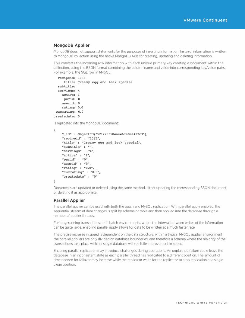
MongoDB ApplierMongoDB does not support statements for the purposes of inserting information. Instead, information is written to MongoDB collection using the native MongoDB APIs for creating, updating and deleting information.
This converts the incoming row information with each unique primary key creating a document within the collection, using the BSON format combining the column name and value into corresponding key/value pairs. For example, the SQL row in MySQL:
recipeid: 1085 title: Creamy egg and leek special subtitle: servings: 4 active: 1 parid: 0 userid: 0 rating: 0.0 cumrating: 0.0createdate: 0
is replicated into the MongoDB document:
{ “_id” : ObjectId(“5212233584ae46ce07e427c3”), “recipeid” : “1085”, “title” : “Creamy egg and leek special”, “subtitle” : “”, “servings” : “4”, “active” : “1”, “parid” : “0”, “userid” : “0”, “rating” : “0.0”, “cumrating” : “0.0”, “createdate” : “0”}
Documents are updated or deleted using the same method, either updating the corresponding BSON document or deleting it as appropriate.
Parallel ApplierThe parallel applier can be used with both the batch and MySQL replication. With parallel apply enabled, the sequential stream of data changes is split by schema or table and then applied into the database through a number of applier threads.
For long-running transactions, or in batch environments, where the interval between writes of the information can be quite large, enabling parallel apply allows for data to be written at a much faster rate.
The precise increase in speed is dependent on the data structure; within a typical MySQL applier environment the parallel appliers are only divided on database boundaries, and therefore a schema where the majority of the transactions take place within a single database will see little improvement in speed.
Enabling parallel replication may introduce challenges during operations. An unplanned failure could leave the database in an inconsistent state as each parallel thread has replicated to a different position. The amount of time needed for failover may increase while the replicator waits for the replicator to stop replication at a single clean position.
T E C H N I C A L W H I T E P A P E R / 2 2
VMware Continuent
Next StepsAdditional DocumentationFor more information about VMware Continuent, please visit the product pages at http://vcloud.vmware.com/service-offering/continuent.
VMware Contact InformationFor additional information or to purchase VMware Continuent, you can reach a sales representative at 1- (877) 486-9273) or email [email protected]. When emailing, please include the state, country, and company name from which you are inquiring.
“By leveraging the VMware Continuent platform, we have increased our ability to provide higher levels of availability and uptime, including complex database upgrades and operations in production. VMware Continuent can help us at least in two ways to lower op-ex: enables more customers on each pod (database cluster) and allows us to use replication between our current hosting provider and another, more cost effective hosting provider to augment pods or completely switch over to save significant money.” — Nick Bonfiglio, VP Operations, Marketo “VMware Continuent is in use for over 40-50 systems and has allowed us to quickly switch from master to slave in several situations with no service interruption.” — Heidi E. Schmidt, Sr. Database Administrator, Constant Contact “Having tried traditional ETL tools and slow data-scraping techniques that put a heavy load on operational systems, we found that we were unable to meet the low latency required by our business as well as capture a complete record of transactions. Hadoop has clearly changed the landscape of data management by providing a central data backbone hub that receives data from across the enterprise business; however, there is now a wide range of services that need to move transaction OLTP data efficiently into Hadoop. With VMware Continuent we can quickly and flexibly move data out of operational databases into Hadoop where we run analytics that answer important business questions on timelines matching the needs of our users.”
— Chris Schneider, Database Architect, Groupon
Providing FeedbackVMware appreciates your feedback on the material included in this guide, and in particular, would be grateful for any guidance on the following topics:
1. How useful was the information in this guide?
2. What other specific topics would you like to see covered?
Please send your feedback to [email protected], with “What’s New with VMware Continuent” in the subject line. Thank you for your help in making this guide a valuable resource.
T E C H N I C A L W H I T E P A P E R / 2 3
VMware Continuent
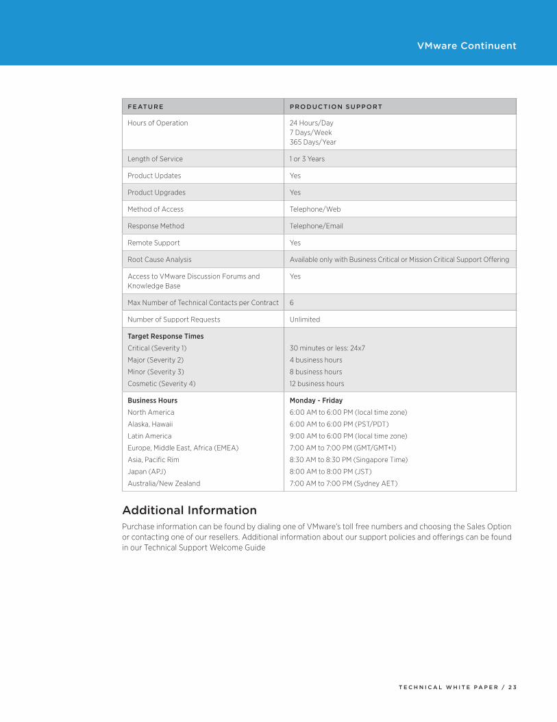
FEATURE PRODUCTION SUPPORT
Hours of Operation 24 Hours/Day 7 Days/Week 365 Days/Year
Length of Service 1 or 3 Years
Product Updates Yes
Product Upgrades Yes
Method of Access Telephone/Web
Response Method Telephone/Email
Remote Support Yes
Root Cause Analysis Available only with Business Critical or Mission Critical Support Offering
Access to VMware Discussion Forums and Knowledge Base
Yes
Max Number of Technical Contacts per Contract 6
Number of Support Requests Unlimited
Target Response Times
Critical (Severity 1)
Major (Severity 2)
Minor (Severity 3)
Cosmetic (Severity 4)
30 minutes or less: 24x7
4 business hours
8 business hours
12 business hours
Business Hours
North America
Alaska, Hawaii
Latin America
Europe, Middle East, Africa (EMEA)
Asia, Pacific Rim
Japan (APJ)
Australia/New Zealand
Monday - Friday
6:00 AM to 6:00 PM (local time zone)
6:00 AM to 6:00 PM (PST/PDT)
9:00 AM to 6:00 PM (local time zone)
7:00 AM to 7:00 PM (GMT/GMT+1)
8:30 AM to 8:30 PM (Singapore Time)
8:00 AM to 8:00 PM (JST)
7:00 AM to 7:00 PM (Sydney AET)
Additional InformationPurchase information can be found by dialing one of VMware’s toll free numbers and choosing the Sales Option or contacting one of our resellers. Additional information about our support policies and offerings can be found in our Technical Support Welcome Guide

VMware, Inc. 3401 Hillview Avenue Palo Alto CA 94304 USA Tel 877-486-9273 Fax 650-427-5001 www .vmware .comCopyright © 2015 VMware, Inc. All rights reserved. This product is protected by U.S. and international copyright and intellectual property laws. VMware products are covered by one or more patents listed at http://www.vmware.com/go/patents. VMware is a registered trademark or trademark of VMware, Inc. in the United States and/or other jurisdictions. All other marks and names mentioned herein may be trademarks of their respective companies. Item No: VMW7424-TWP-CONTINUENT-ARCH-OVERVIEW-USLET-103 04/15


![Continuent Tungsten 1.5 Manual - VMware · 2015-04-16 · [Continuent Tungsten 2.0 Manual]) or shun the datasource before restarting the replicator (Shunning a Datasource in [Continuent](https://img.pdfslide.us/doc/110x75/5e6a9c98cbfaac1b33722d10/continuent-tungsten-15-manual-vmware-2015-04-16-continuent-tungsten-20-manual.jpg)