Embed Size (px)
Citation preview
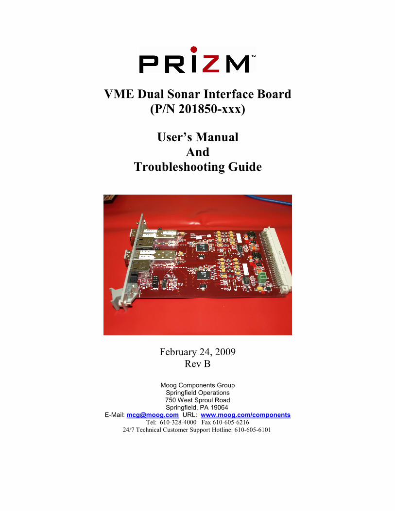
VME Dual Sonar Interface Board
(P/N 201850-xxx)
User’s Manual
And
Troubleshooting Guide
February 24, 2009
Rev B
Moog Components Group
Springfield Operations 750 West Sproul Road
Springfield, PA 19064 E-Mail: [email protected] URL: www.moog.com/components
Tel: 610-328-4000 Fax 610-605-6216
24/7 Technical Customer Support Hotline: 610-605-6101
MOOG CG 201850-xxx VME Dual Sonar Board Manual Revision B 2/24/09
Page 2 of 14
MANUAL REVISION HISTORY
REVISION
NUMBER
DATE BY REASON FOR
REVISION
Preliminary-Rev A 8/7/08 GSG ORIGINAL
Rev B 2/24/09 IB Updated contact information to reflect
Moog Components Group
TABLE OF CONTENTS
1 VME DUAL SONAR BOARD, P/N: 201850-XXX....................................................................... 3
1.1 VME DUAL SONAR BOARD REVISION HISTORY: ............................................................................ 3 1.2 VME DUAL SONAR BOARD DASH (-) NUMBER DEFINITIONS.......................................................... 3 1.3 VME DUAL SONAR BOARD OPERATION: ........................................................................................ 3
1.3.1 Dual Sonar Board Jumper Shunt Drawings:................................................ 11
1.3.2 VME Dual Sonar Board Specifications: ....................................................... 11
1.3.3 VME Dual Sonar Board Dimensions:........................................................... 11
1.3.4 Dual Sonar Board Power Requirements: ..................................................... 11
1.3.5 Power Section Testing................................................................................... 11
1.3.6 Optical Section Testing ................................................................................. 12 1.4 VME SYSTEM INSTALLATION CHECKOUT PROCEDURE................................................................. 13
1.4.1 Diagnostics Overview ................................................................................... 13
1.4.2 Required Communications Hardware for Diagnostics................................. 13
MOOG CG 201850-xxx VME Dual Sonar Board Manual Revision B 2/24/09
Page 3 of 14
1 VME Dual Sonar Board, P/N: 201850-xxx
The Prizm VME Dual Sonar Board provides two independent fiber optic links to remote the
Reson 8xxx and Simrad EM3002 single/dual beam sonars. The Dual Sonar Board can be
jumper selected to support both single-ended (single coax) Reson sonars and differential
(dual coax) Simrad sonars. This board only provides for the sonar’s uplink (subsea to
surface) data link, the downlink (surface to subsea) control link must be handled through
another separate multiplexer. The control link for the Reson and Simrad sonars may require
specific electrical protocols (i.e. RS-232, RS-485, RS-422 or other) and the sonar
manufacturer’s interface manual should be consulted.
The Dual Sonar Board can be jumper configured to operate as either a subsea or surface
interface board, so can be used as spare for either location. The optical modules used on the
board (pluggable small-form-factor (SFP)) are inherently bi-directional and care must be
taken to ensure the correct optical port (either TX or RX) is connected, depending on the
board configuration and system location. While the optical module’s receiver will operate
on all of the 16 CWDM wavelengths (1270 to 1610nm), the module’s transmitter only emits
at a single wavelength so care must be taken to ensure the correct wavelength is used.
The Dual Sonar Board supports PMON II diagnostics through the RS-485 diagnostics cable.
Diagnostics will display the optical parameters from both of the SFP modules and will also
show the sonar activity (both into and out of the board) on PMON II. Note: to acquire
diagnostics from the remote Dual Sonar Board, the board must be connected to an RS-485
channel on a Submux RS-485 daughterboard.
1.1 VME Dual Sonar Board Revision History:
The VME Dual Sonar Board has gone through the following printed circuit board (PCB)
and Assembly revisions:
PCB Revision A/Assembly Revision A Original design.
1.2 VME Dual Sonar Board Dash (-) Number Definitions
The VME Dual Sonar Board has a Dash Number appended to the part number. This
Dash Number identifies the specific board configurations:
-001x 50-Ohm SMB connectors
NOTE: the x after the dash number denotes the assembly revision letter.
1.3 VME Dual Sonar Board Operation:
Each independent sonar link has two 50-ohm SMB coaxial connectors. These connectors
will be active as inputs or outputs depending on the jumper settings. For single-ended
(single coax) sonars, only the top SMB connector will be active (labeled IN/OUT A+ or
IN/OUT B+). For differential (dual coax) sonars, both of the connectors will be used.
MOOG CG 201850-xxx VME Dual Sonar Board Manual Revision B 2/24/09
Page 4 of 14
NOTE: While 50-Ohm SMB connectors are standard, Prizm supports both the 50-
Ohm and the 75-Ohm SMB connectors to meet the customer’s needs.
The sonar fiber links are identified as link “A/#1” or “B/#2”.
Normally, DC operating power for the board is supplied via the DIN backplane connector.
Alternately, there is single green 2-pin Phoenix connector on the on the right side of the
board for supplying the board with +5VDC. Pin 1 is the +5VDC input and pin 2 is the
ground. There is single black 3-pin Phoenix connector on the on the bottom left side of the board for
RS-485 diagnostics. Pin 1 is the RT+ signal, pin 2 is the ground/shield and pin 3 is the RT-
signal. A Prizm Diagnostics cable can be connected directly to this 3-pin connector or
through a RS-485 channel on a Submux RS-485 daughterboard.
NOTE: To complete the RS-485 diagnostics link from the surface to the subsea boards, the Dual Sonar
Board must be stacked onto a VME Video RS-485 channel on a Submux RS-485 daughterboard to
complete the link over the multiplexer’s fiber. Dual Sonar Board Indicators and Controls:
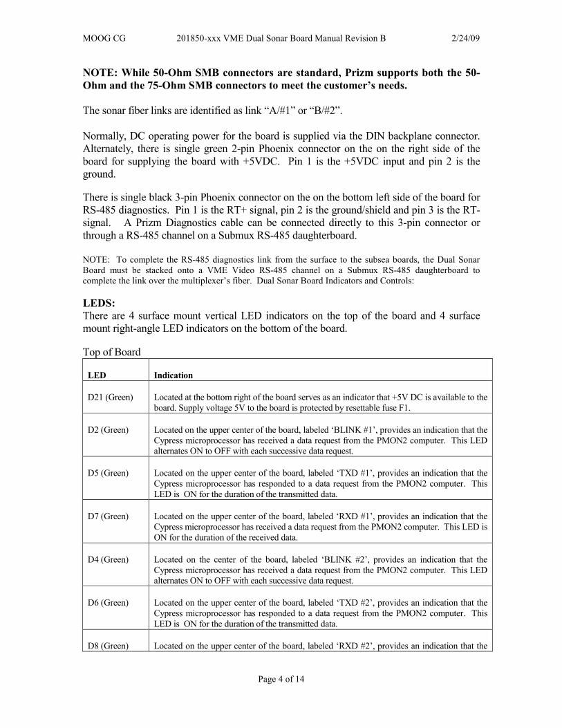
LEDS:
There are 4 surface mount vertical LED indicators on the top of the board and 4 surface
mount right-angle LED indicators on the bottom of the board.
Top of Board
LED Indication
D21 (Green) Located at the bottom right of the board serves as an indicator that +5V DC is available to the
board. Supply voltage 5V to the board is protected by resettable fuse F1.
D2 (Green) Located on the upper center of the board, labeled ‘BLINK #1’, provides an indication that the
Cypress microprocessor has received a data request from the PMON2 computer. This LED
alternates ON to OFF with each successive data request.
D5 (Green) Located on the upper center of the board, labeled ‘TXD #1’, provides an indication that the
Cypress microprocessor has responded to a data request from the PMON2 computer. This
LED is ON for the duration of the transmitted data.
D7 (Green) Located on the upper center of the board, labeled ‘RXD #1’, provides an indication that the
Cypress microprocessor has received a data request from the PMON2 computer. This LED is
ON for the duration of the received data.
D4 (Green) Located on the center of the board, labeled ‘BLINK #2’, provides an indication that the
Cypress microprocessor has received a data request from the PMON2 computer. This LED
alternates ON to OFF with each successive data request.
D6 (Green) Located on the upper center of the board, labeled ‘TXD #2’, provides an indication that the
Cypress microprocessor has responded to a data request from the PMON2 computer. This
LED is ON for the duration of the transmitted data.
D8 (Green) Located on the upper center of the board, labeled ‘RXD #2’, provides an indication that the
MOOG CG 201850-xxx VME Dual Sonar Board Manual Revision B 2/24/09
Page 5 of 14
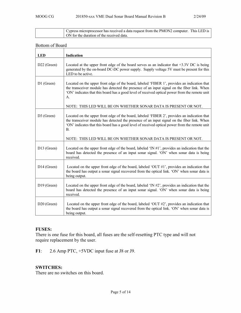
Cypress microprocessor has received a data request from the PMON2 computer. This LED is
ON for the duration of the received data.
Bottom of Board
LED Indication
D22 (Green) Located at the upper front edge of the board serves as an indicator that +3.3V DC is being
generated by the on-board DC-DC power supply. Supply voltage 5V must be present for this
LED to be active.
D1 (Green) Located on the upper front edge of the board, labeled ‘FIBER 1’, provides an indication that
the transceiver module has detected the presence of an input signal on the fiber link. When
‘ON’ indicates that this board has a good level of received optical power from the remote unit
A.
NOTE: THIS LED WILL BE ON WHETHER SONAR DATA IS PRESENT OR NOT.
D3 (Green) Located on the upper front edge of the board, labeled ‘FIBER 2’, provides an indication that
the transceiver module has detected the presence of an input signal on the fiber link. When
‘ON’ indicates that this board has a good level of received optical power from the remote unit
B.
NOTE: THIS LED WILL BE ON WHETHER SONAR DATA IS PRESENT OR NOT.
D13 (Green) Located on the upper front edge of the board, labeled ‘IN #1’, provides an indication that the
board has detected the presence of an input sonar signal. ‘ON’ when sonar data is being
received.
D14 (Green) Located on the upper front edge of the board, labeled ‘OUT #1’, provides an indication that
the board has output a sonar signal recovered from the optical link. ‘ON’ when sonar data is
being output.
D19 (Green) Located on the upper front edge of the board, labeled ‘IN #2’, provides an indication that the
board has detected the presence of an input sonar signal. ‘ON’ when sonar data is being
received.
D20 (Green) Located on the upper front edge of the board, labeled ‘OUT #2’, provides an indication that
the board has output a sonar signal recovered from the optical link. ‘ON’ when sonar data is
being output.
FUSES:
There is one fuse for this board, all fuses are the self-resetting PTC type and will not
require replacement by the user.
F1: 2.6 Amp PTC, +5VDC input fuse at J8 or J9.
SWITCHES:
There are no switches on this board.
MOOG CG 201850-xxx VME Dual Sonar Board Manual Revision B 2/24/09
Page 6 of 14
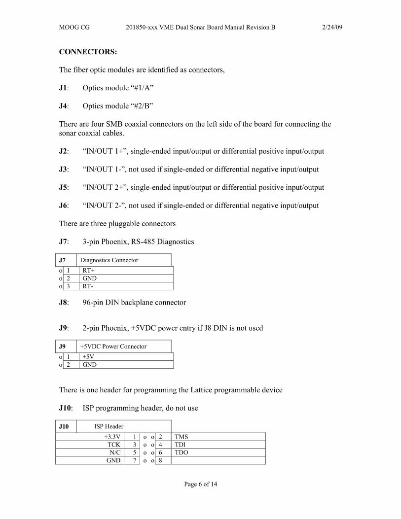
CONNECTORS:
The fiber optic modules are identified as connectors,
J1: Optics module “#1/A”
J4: Optics module “#2/B”
There are four SMB coaxial connectors on the left side of the board for connecting the
sonar coaxial cables.
J2: “IN/OUT 1+”, single-ended input/output or differential positive input/output
J3: “IN/OUT 1-”, not used if single-ended or differential negative input/output
J5: “IN/OUT 2+”, single-ended input/output or differential positive input/output
J6: “IN/OUT 2-”, not used if single-ended or differential negative input/output
There are three pluggable connectors
J7: 3-pin Phoenix, RS-485 Diagnostics
J7 Diagnostics Connector
o 1 RT+
o 2 GND
o 3 RT-
J8: 96-pin DIN backplane connector
J9: 2-pin Phoenix, +5VDC power entry if J8 DIN is not used
J9 +5VDC Power Connector
o 1 +5V
o 2 GND
There is one header for programming the Lattice programmable device
J10: ISP programming header, do not use
J10 ISP Header
+3.3V 1 o o 2 TMS
TCK 3 o o 4 TDI
N/C 5 o o 6 TDO
GND 7 o o 8
MOOG CG 201850-xxx VME Dual Sonar Board Manual Revision B 2/24/09
Page 7 of 14
NOTE: J12 to be used only by PRIZM.
JP13: Cypress #1 ISP programming header, do not use
NOTE: JP13 to be used only by PRIZM.
JP27: Cypress #1 ISP programming header, do not use
NOTE: JP27 to be used only by PRIZM.
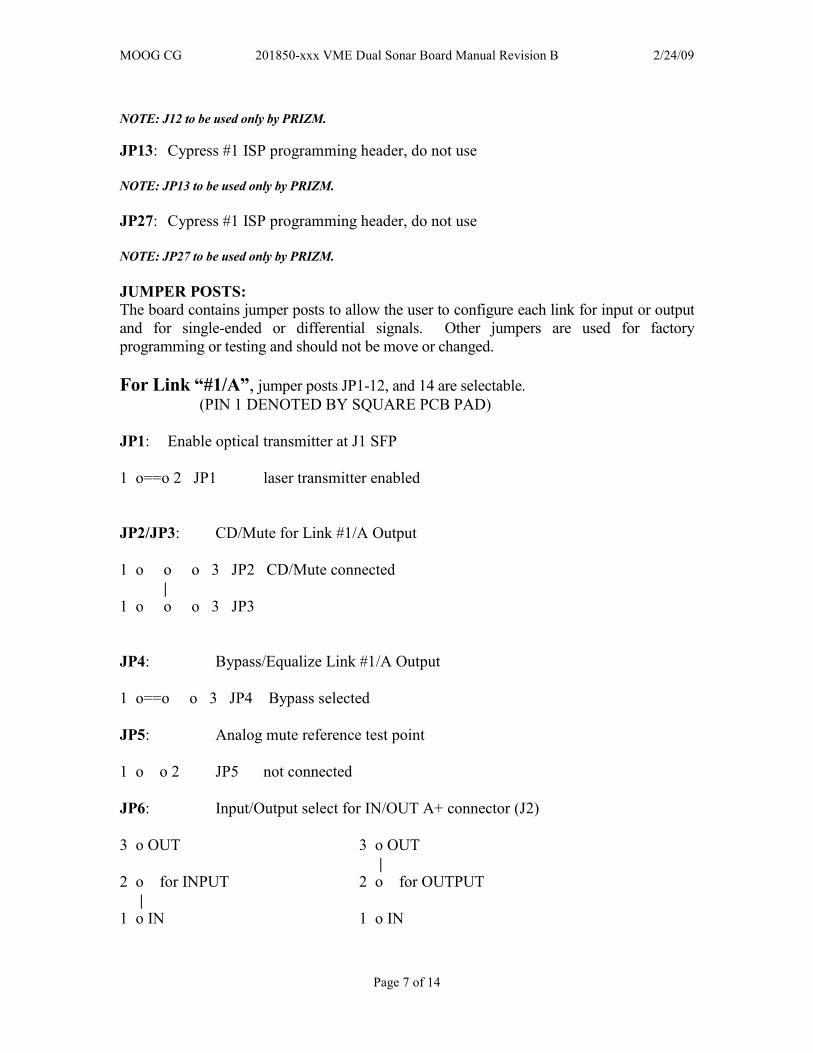
JUMPER POSTS:
The board contains jumper posts to allow the user to configure each link for input or output
and for single-ended or differential signals. Other jumpers are used for factory
programming or testing and should not be move or changed.
For Link “#1/A”, jumper posts JP1-12, and 14 are selectable.
(PIN 1 DENOTED BY SQUARE PCB PAD)
JP1: Enable optical transmitter at J1 SFP
1 o==o 2 JP1 laser transmitter enabled
JP2/JP3: CD/Mute for Link #1/A Output
1 o o o 3 JP2 CD/Mute connected
|
1 o o o 3 JP3
JP4: Bypass/Equalize Link #1/A Output
1 o==o o 3 JP4 Bypass selected
JP5: Analog mute reference test point
1 o o 2 JP5 not connected
JP6: Input/Output select for IN/OUT A+ connector (J2)
3 o OUT 3 o OUT
|
2 o for INPUT 2 o for OUTPUT
|
1 o IN 1 o IN
MOOG CG 201850-xxx VME Dual Sonar Board Manual Revision B 2/24/09
Page 8 of 14
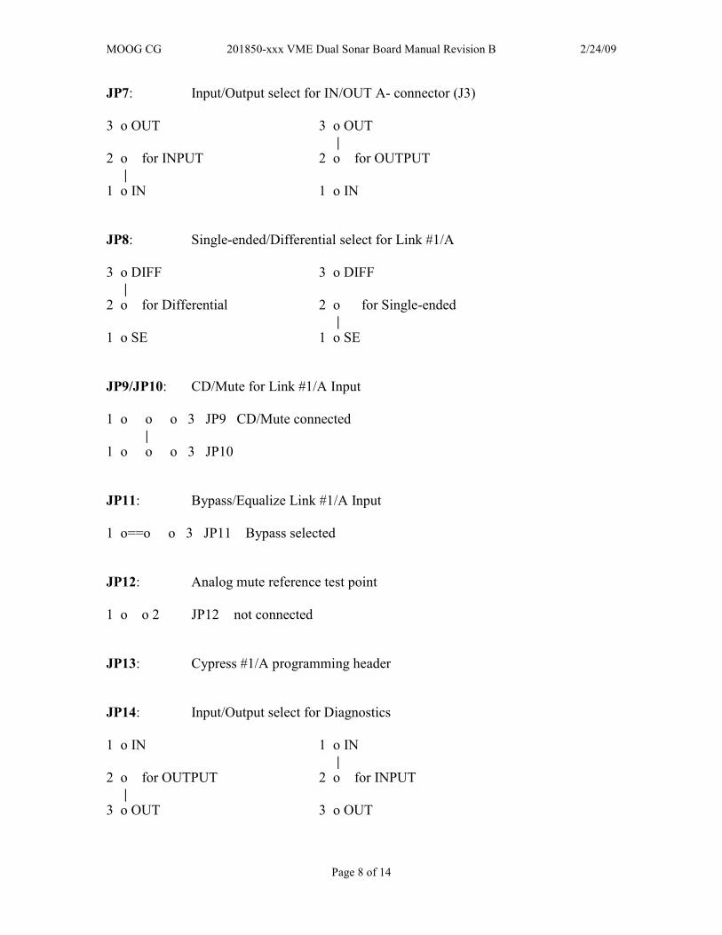
JP7: Input/Output select for IN/OUT A- connector (J3)
3 o OUT 3 o OUT
|
2 o for INPUT 2 o for OUTPUT
|
1 o IN 1 o IN
JP8: Single-ended/Differential select for Link #1/A
3 o DIFF 3 o DIFF
|
2 o for Differential 2 o for Single-ended
|
1 o SE 1 o SE
JP9/JP10: CD/Mute for Link #1/A Input
1 o o o 3 JP9 CD/Mute connected
|
1 o o o 3 JP10
JP11: Bypass/Equalize Link #1/A Input
1 o==o o 3 JP11 Bypass selected
JP12: Analog mute reference test point
1 o o 2 JP12 not connected
JP13: Cypress #1/A programming header
JP14: Input/Output select for Diagnostics
1 o IN 1 o IN
|
2 o for OUTPUT 2 o for INPUT
|
3 o OUT 3 o OUT
MOOG CG 201850-xxx VME Dual Sonar Board Manual Revision B 2/24/09
Page 9 of 14
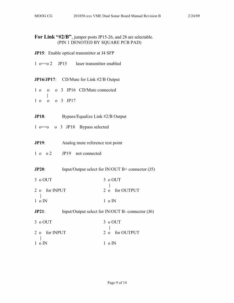
For Link “#2/B”, jumper posts JP15-26, and 28 are selectable.
(PIN 1 DENOTED BY SQUARE PCB PAD)
JP15: Enable optical transmitter at J4 SFP
1 o==o 2 JP15 laser transmitter enabled
JP16/JP17: CD/Mute for Link #2/B Output
1 o o o 3 JP16 CD/Mute connected
|
1 o o o 3 JP17
JP18: Bypass/Equalize Link #2/B Output
1 o==o o 3 JP18 Bypass selected
JP19: Analog mute reference test point
1 o o 2 JP19 not connected
JP20: Input/Output select for IN/OUT B+ connector (J5)
3 o OUT 3 o OUT
|
2 o for INPUT 2 o for OUTPUT
|
1 o IN 1 o IN
JP21: Input/Output select for IN/OUT B- connector (J6)
3 o OUT 3 o OUT
|
2 o for INPUT 2 o for OUTPUT
|
1 o IN 1 o IN
MOOG CG 201850-xxx VME Dual Sonar Board Manual Revision B 2/24/09
Page 10 of 14
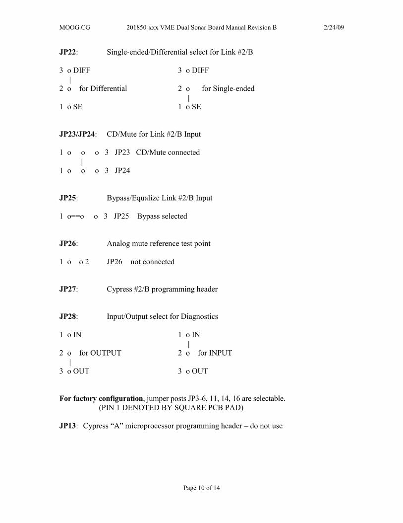
JP22: Single-ended/Differential select for Link #2/B
3 o DIFF 3 o DIFF
|
2 o for Differential 2 o for Single-ended
|
1 o SE 1 o SE
JP23/JP24: CD/Mute for Link #2/B Input
1 o o o 3 JP23 CD/Mute connected
|
1 o o o 3 JP24
JP25: Bypass/Equalize Link #2/B Input
1 o==o o 3 JP25 Bypass selected
JP26: Analog mute reference test point
1 o o 2 JP26 not connected
JP27: Cypress #2/B programming header
JP28: Input/Output select for Diagnostics
1 o IN 1 o IN
|
2 o for OUTPUT 2 o for INPUT
|
3 o OUT 3 o OUT
For factory configuration, jumper posts JP3-6, 11, 14, 16 are selectable.
(PIN 1 DENOTED BY SQUARE PCB PAD)
JP13: Cypress “A” microprocessor programming header – do not use
MOOG CG 201850-xxx VME Dual Sonar Board Manual Revision B 2/24/09
Page 11 of 14
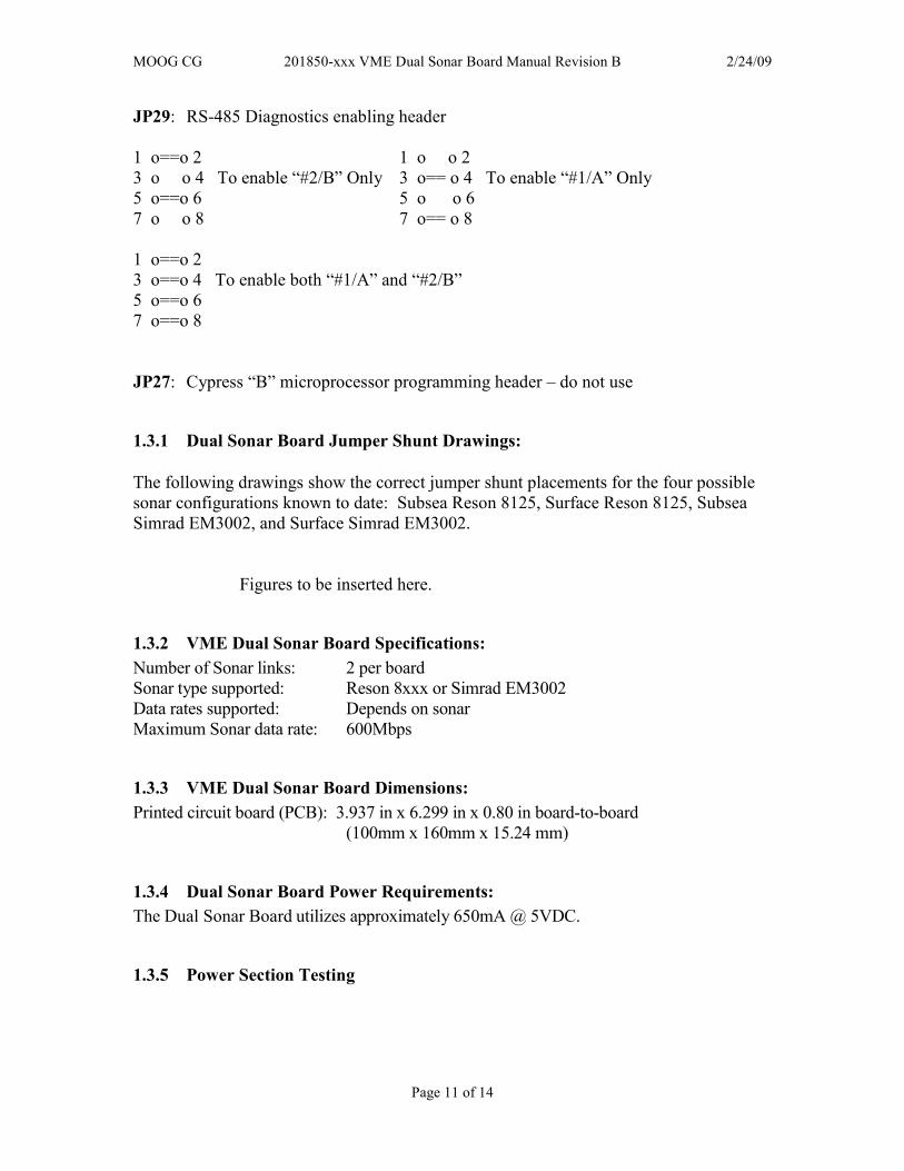
JP29: RS-485 Diagnostics enabling header
1 o==o 2 1 o o 2
3 o o 4 To enable “#2/B” Only 3 o== o 4 To enable “#1/A” Only
5 o==o 6 5 o o 6
7 o o 8 7 o== o 8
1 o==o 2
3 o==o 4 To enable both “#1/A” and “#2/B”
5 o==o 6
7 o==o 8
JP27: Cypress “B” microprocessor programming header – do not use
1.3.1 Dual Sonar Board Jumper Shunt Drawings:
The following drawings show the correct jumper shunt placements for the four possible
sonar configurations known to date: Subsea Reson 8125, Surface Reson 8125, Subsea
Simrad EM3002, and Surface Simrad EM3002.
Figures to be inserted here.
1.3.2 VME Dual Sonar Board Specifications:
Number of Sonar links: 2 per board
Sonar type supported: Reson 8xxx or Simrad EM3002
Data rates supported: Depends on sonar
Maximum Sonar data rate: 600Mbps
1.3.3 VME Dual Sonar Board Dimensions:
Printed circuit board (PCB): 3.937 in x 6.299 in x 0.80 in board-to-board
(100mm x 160mm x 15.24 mm)
1.3.4 Dual Sonar Board Power Requirements:
The Dual Sonar Board utilizes approximately 650mA @ 5VDC.
1.3.5 Power Section Testing

MOOG CG 201850-xxx VME Dual Sonar Board Manual Revision B 2/24/09
Page 12 of 14
NOTE: The connectors on the bottom of the Dual Sonar Board have pins that are
connected to +5VDC and ground. If these pins are inadvertently shorted together or to a
common chassis ground, the board fuse (F1) will trip/reset.
If both the +5V Power LED +3.3V Power LED are out:
• Check for continuity of PTC fuse F1 with an ohmmeter.
• Replace PTC fuse if open.
If only the +5V Power LED is out:
• Verify +5V DC is present at the source
• At J9 if powered off of external power
• At J8 if powered off of the backplane
• If +5V is not available replace the board with a spare.
• If +5V is available check the display LED (D21).
If only the +3.3V Power LED is out:
• Verify +5VDC at F1 (replace board if +5VDC is not available)
• Verify +3.3VDC across C127 on top of board
• If +3.3V is not available replace the board with a spare.
• If +3.3V is available check the display LED (D22).
1.3.6 Optical Section Testing
For surface boards, if the “FIBER 1” or “FIBER 2” LED is off or flickering, one or more
of the following conditions is likely:
• The fiber is broken or damaged.
• The optical transceiver module is defective at either the surface or subsea board.
• Excessive light loss (low received optical power) is being experienced.
• The VME board (not the optical transceiver module) is malfunctioning.
• There is not enough attenuation in the optical link and the receiver is saturating.
If excessive optical loss is being experienced, the following conditions may be present:
• May have sonar data errors.
• Check the optical level with an optical power meter and inspect all fiber optic
connections including CWDMs and slip rings.
To determine if the fiber is broken, a laser module is out, or the board is malfunctioning,
first:
• Verify that the optical transceiver is tight in its socket.
• Verify that shunts (jumpers) are placed per system jumper configuration.
• Check all fiber optic connections including CWDMs and slip rings to make sure that
they are not causing the problem.
• Check that the optical fiber cable is straight at connectors on board for minimum
optic loss.
MOOG CG 201850-xxx VME Dual Sonar Board Manual Revision B 2/24/09
Page 13 of 14
1.4 VME System Installation Checkout Procedure
NOTE: The Dual Sonar Board will work in a stand-alone configuration without an RS-
485 channel on a Submux RS-485 daughterboard. Without an RS-485 channel on a
Submux RS-485 daughterboard, the subsea diagnostics will not work but the board will
still carry a sonar signal.
For this VME System installation checkout procedure, it is assumed that the VME System is
composed of a Sonar board mounted in the vehicle and a Sonar board on the surface.
+5VDC power for the VME boards is supplied by the user’s DC power supply powering the
VME rack and should be verified to be between +4.75VDC and +5.25VDC at the 2-pin
Phoenix power connector or at the backplane.
1.4.1 Diagnostics Overview
The Dual Sonar Board has been designed to include hardware and firmware for monitoring
various parameters of interest. This capability is accessed via a 3-pin Phoenix connector on
the board that carries bi-directional RS-485 telemetry. The diagnostics will typically be
used in conjunction with a user-supplied PC on the surface, which has been loaded with
PRIZM Modem Monitoring S/W (PMON II).
For the Dual Sonar board, the Diagnostics feature requires that there be a functioning
multiplexer system for connectivity between the topside Diagnostic PC and the remote
multiplexer.
NOTE: The diagnostics feature in no way interferes with normal operation of the
modem – it is not necessary to be running the diagnostics software for any of the
VME boards to work.
1.4.2 Required Communications Hardware for Diagnostics
The diagnostics capability is accessed via the 3-pin Phoenix connector on the VME boards,
which provides the RS-485 connectivity to the on-board processor for diagnostics
communications. RS-485 was used because of its multi-drop capability, which in this case
allows all the VME boards to be communicated with via a single channel. In this
configuration, no RS-485 multiplexer channel is needed.
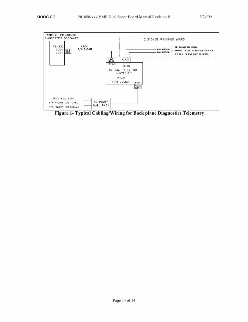
The user is required to communicate with the VME boards of the system via RS-485. A
typical installation is shown in the following drawing. This details a diagnostic connection
from a Windows PC running PMON II to a VME system.
MOOG CG 201850-xxx VME Dual Sonar Board Manual Revision B 2/24/09
Page 14 of 14
Figure 1- Typical Cabling/Wiring for Back plane Diagnostics Telemetry